1
ALESIS
Wedge
Reference Manual
Introduction
Thank you for purchasing the Alesis Wedge Desktop Master Reverb Processor. To
take full advantage of the Wedge’s functions, and to enjoy long and trouble-free use,
please read this user’s manual carefully.
How To Use This Manual
This manual is divided into the following sections describing the various modes of
the Wedge. Though we recommend you take time to read through the entire manual
once carefully, those having general knowledge about effects devices should use the
table of contents to reference specific functions.
Chapter 1: Your First Session with the Wedge. A basic introduction to getting the
unit up and running, auditioning the factory Programs, adjusting levels, comparing
and storing edited Programs.
Chapter 2: Connections. Deals with the necessary preparation before using,
including connections to other components, such as instruments, mixing consoles,
patchbays, and multitrack recorders.
Chapter 3: Description of Controls. A “dictionary” of all buttons, connectors, and
Utility parameters. Use this chapter as a quick reference guide when searching for
specific information.
Chapter 4: Editing Programs. A guided tour for programming typical single and
multi-effect applications.
Chapter 5: Overview of Effects. A detailed look at the signal processing capabilities
of the Wedge and the concept of reverb and effects programming. Includes
descriptions of each parameter in the Wedge.
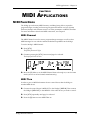
Chapter 6: MIDI Applications. This chapter discusses the various MIDI functions,
such as recalling Programs, realtime modulation of parameters, and Sysex data
transfer.
Chapter 7: Trouble-Shooting. Contains the Trouble-shooting Index, maintenance
and service information, and MIDI implementation chart.
Appendices. MIDI basics, trouble-shooting, maintenance and service information,
MIDI Implementation Chart and an Index.
Conventions
The buttons, knobs, and rear panel connectors are referred to in this manual just as
their names appear on the Wedge, using all capital letters and in brackets (Example:
[PROG] button, [VALUE] Knob, etc.). When text in the Wedge’s display is quoted,
it is indicated using special typeface (Example: 00 to127, DELAY}REVERB, etc.).
J
When something important appears in the manual, an icon (like the one on the left) will
appear in the left margin. This symbol indicates vital information when operating the Wedge.
Wedge Reference Manual
1
2
Wedge Reference Manual
Wedge Reference Manual
3
Contents
CONTENTS
Your First Session with the Wedge............................................7
Unpacking and Inspection ..................................................................................................7
Basic Connections................................................................................................................7
Powering Up ........................................................................................................................8
Dry Defeat............................................................................................................................8
Setting Levels .......................................................................................................................8
Automatic Input Level Settings ............................................................................9
What’s in the Display? ........................................................................................................10
Auditioning Internal Programs ..........................................................................................10
Switching Between Preset and User Banks..........................................................10
Changing Effect Settings .....................................................................................................11
Using Online Help .................................................................................................12
Adjusting Effects Mix Levels ................................................................................13
Comparing an Edited Program to its Original Settings ...................................................13
Restoring an Edited Program to its Original Settings ......................................................14
Bypassing Effects .................................................................................................................14
Storing and Naming Edited Programs ..............................................................................15
Connections .................................................................................17
AC Power Hookup ..............................................................................................................17
Line Conditioners and Protectors.........................................................................17
Audio Connections..............................................................................................................17
Typical Applications..............................................................................................18
Input Jack Wiring...................................................................................................18
Balanced Operation..................................................................................19
Interfacing Directly with Instruments..................................................................19
Using the Aux Sends................................................................................21
Using Inserts .............................................................................................23
Using Main Outputs.................................................................................24
Avoiding Ground Loops .......................................................................................24
MIDI Connections ...............................................................................................................25
Description of Controls ................................................................27
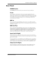
Front Panel ...........................................................................................................................27
LCD Display...........................................................................................................27
VALUE Knob .........................................................................................................28
EDIT/PAGE Button...............................................................................................28
TAP/AUDITION Button.......................................................................................29
A/B/C/D (NAME/ESC/</>) Buttons...............................................................29
A/B/C/D Sliders...................................................................................................29
PROGram Button ...................................................................................................30
UTILity Button .......................................................................................................30
I/O Button ..............................................................................................................32
STORE Button ........................................................................................................33
COMPARE Button .................................................................................................33
BYPASS Button ......................................................................................................33
Rear Panel.............................................................................................................................34
4
Wedge Reference Manual
Contents
Power Switch..........................................................................................................34
Power ......................................................................................................................34
MIDI In ...................................................................................................................34
MIDI Out/Thru......................................................................................................34
Input (Left & Right) ...............................................................................................34
Output (Left & Right) ............................................................................................34
Editing Programs .........................................................................35
Selecting A Configuration...................................................................................................35
Editing Effect Parameters ...................................................................................................36
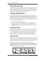
Moving Through Pages .........................................................................................37
Using the A/B/C/D Buttons................................................................................37
Using Online Help .................................................................................................37
Special Cases ..........................................................................................................37
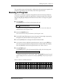
Naming A Program .............................................................................................................38
Tutorial: Gothic Hall ...........................................................................................................39
Overview of Effects .....................................................................41
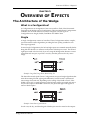
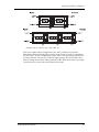
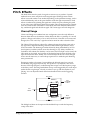
The Architecture of the Wedge ..........................................................................................41
What is a Configuration?.......................................................................................41
Single.......................................................................................................................41
Parallel ....................................................................................................................41
Dual Mono..............................................................................................................41
Multi Chain.............................................................................................................41
Reverb Effects ......................................................................................................................44
Large Hall ...............................................................................................................44
Hall Reverb.............................................................................................................44
Room Reverb..........................................................................................................44
Chamber .................................................................................................................44
Ambience................................................................................................................44
Stereo Room ...........................................................................................................44
Large Plate..............................................................................................................44
Plate.........................................................................................................................45
Nonlinear................................................................................................................45
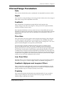
Reverb Parameters...............................................................................................................46
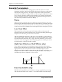
Decay ......................................................................................................................46
Low Pass Filter .......................................................................................................46
High Pass Filter/Low Shelf...................................................................................46
Bass Boost ...............................................................................................................46
Pre-delay.................................................................................................................47
Pre-delay Mix .........................................................................................................47
Density....................................................................................................................47
Diffusion .................................................................................................................47
Frequency Damping – Low & High .....................................................................48
ER: Early Reflections (Spread, Shape and Level) ................................................48
Depth ......................................................................................................................49
Width ......................................................................................................................49
Reverberation Swirl ...............................................................................................49
Gating......................................................................................................................49
Delay Effects ........................................................................................................................50
Mono Delay ............................................................................................................50
Delay:Delay ............................................................................................................50
Wedge Reference Manual
5
Contents
Ping Pong Delay.....................................................................................................50
MultiTap Delay ......................................................................................................50
Setting Delay Time Using Tap Tempo....................................................50
Delay Parameters.................................................................................................................51
Delay Time .............................................................................................................51
Tap ..........................................................................................................................51
Feedback .................................................................................................................51
Low Cut/High Cut ................................................................................................51
Density....................................................................................................................51
Rate/Depth.............................................................................................................51
Tremolo Rate/Depth .............................................................................................52
Pan Rate/Depth .....................................................................................................52
Pitch Effects..........................................................................................................................53
Chorus/Flange .......................................................................................................53
Quad Chorus ..........................................................................................................54
Quad Pitch Shifter..................................................................................................54
Chorus:Chorus .......................................................................................................54
Chorus.....................................................................................................................54
Lezlie.......................................................................................................................54
Pitch Parameters ..................................................................................................................55
Rate .........................................................................................................................55
Depth ......................................................................................................................55
Feedback .................................................................................................................55
Thru Zero................................................................................................................55
Low Pass Filter .......................................................................................................55
Feedback Highpass and Lowpass Filters .............................................................55
Predelay ..................................................................................................................55
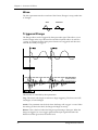
Wave .......................................................................................................................56
Triggered Flange ....................................................................................................56
Width ......................................................................................................................57
Level........................................................................................................................57
Motor, Speed, High Rotor Level...........................................................................57
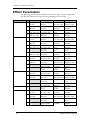
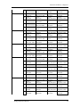
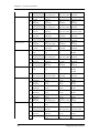
Effect Parameters.................................................................................................................58
MIDI Applications.........................................................................65
MIDI Functions....................................................................................................................65
MIDI Channel.........................................................................................................65
MIDI Thru ..............................................................................................................65
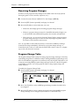
Receiving Program Changes .................................................................................66
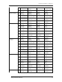
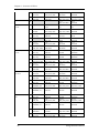
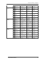
Program Change Table ..........................................................................................66
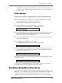
Sysex Storage..........................................................................................................67
Realtime Modulation Functions .........................................................................................67
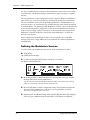
Defining the Modulation Sources.........................................................................68
Modulation Parameters Index ..............................................................................69
Setting Modulation Amplitude.............................................................................70
Realtime Sysex Control..........................................................................................71
About System Exclusive vs. Controller Messages ..............................................71
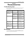
Troubleshooting ...........................................................................73
Trouble-Shooting Index ......................................................................................................73
Re-initializing.......................................................................................................................73
Checking the Software Version ..........................................................................................74
6
Wedge Reference Manual
Contents
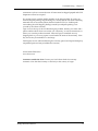
Maintenance/Service ..........................................................................................................74
Cleaning..................................................................................................................74
Refer All Services to Alesis ...................................................................................74
Obtaining Repair Service.......................................................................................74
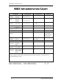
MIDI Implementation Chart..........................................................76
Specifications ..............................................................................77
Wedge Reference Manual
7
Contents
(GFX: Front & Rear Panel Diagram)
8
Wedge Reference Manual
Your First Session with the Wedge – Chapter 1
CHAPTER 1
YOUR FIRST SESSION WITH
THE WEDGE
Unpacking and Inspection
Your Wedge was packed carefully at the factory, and the shipping carton was
designed to protect the unit during shipping. Please retain this container in the
highly unlikely event that you need to return the Wedge for servicing.
The shipping carton should contain the following items:
•
•
•
•
•
J
This instruction manual
Alesis Wedge with the same serial number as shown on shipping carton
Program Chart
AC Power Supply Adapter
Alesis warranty card
It is important to register your purchase; if you have not already filled out your warranty
card and mailed it back to Alesis, please take the time to do so now.
Basic Connections
The Wedge is designed to accommodate a number of applications, whether you are
connecting it with a mixing console or connecting an instrument directly into it.
Briefly described here are the basic connections to get you up and running quickly.
For more information on connections, please refer to Chapter 2.
•
Mono In, Mono or Stereo Out: Connect a 1/4” phone cord to the [LEFT] INPUT
of the Wedge from a mono source The [LEFT] INPUT is normalled to the
[RIGHT] INPUT. This means if you just connect the [LEFT] INPUT, and leave the
the [RIGHT] INPUT unplugged, the same signal will be sent to both Inputs.
Connect another cable from the [LEFT] OUTPUT of the Wedge to an amplifier or
mixer input. Additionally, you could connect a second cable to the [RIGHT]
OUTPUT for use with a stereo amplification system, or two mixer inputs.
•
Stereo: Connect two 1/4” phone cords to the [LEFT] & [RIGHT] INPUTS of the
Wedge from a stereo source , and two 1/4” phone cords from the OUTPUTS of
the Wedge to a stereo amplification system or two mixer inputs.
Wedge Reference Manual
7
Chapter 1 – Your First Session with the Wedge
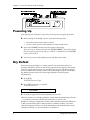
Powering Up
After making your connections, turn on the system’s power using this procedure:
Ê Before turning on the Wedge’s power, check the following items:
•
•
Have all connections been made correctly?
Are the volume controls of the amplifier or mixer turned down?
Ë Turn on the [POWER] switch on the front panel of the Wedge.
Upon power-up, the display will briefly read “ALESIS WEDGE”, and will then display
the last selected Program Number (00–127, PRESET or USER Bank), and the [PROG]
button’s LED will be lit.
Ì Turn on the power of the amplifier/mixer, and adjust the volume.
Dry Defeat
When connecting the Wedge to a mixing console’s aux sends and returns, it is
generally desirable to remove the direct (dry) signal from the outputs of the Wedge
so that its output signal contains only the effected (wet) signal. The dry signal may
then be combined at the mixing console with the returning wet signal. The Wedge’s
Dry Defeat function removes the direct signal globally from all Programs
simultaneously.
Ê Press [UTIL].
The [UTIL] button will light.
Ë Press [EDIT] until page 1 is selected.
The display will read:
Dry Defeat
Ì Press [D] to toggle the Dry Defeat parameter ON or OFF.
When Dry Defeat is On, the Mix parameter of each effect (described later) will read “- -” to indicate it cannot be edited (it is fixed at 100%). Exceptions: The
RealRoom −>Flange Configuration will have its Reverb Mix parameter disabled (set
at 100%), but the Flange effect’s Mix will still be available for editing. The Lezlie>Room configuration will have its Lezlie Mix disabled, but the Reverb Mix will be
available for editing. For more information, see Chapter 2.
8
Wedge Reference Manual
Your First Session with the Wedge – Chapter 1
Setting Levels
Proper setting of the input and output levels is crucial in order to achieve the
maximum signal-to-noise ratio. As a good rule of thumb, it is usually best to set both
input and output level controls at 90% of full. This will decrease the possibility of
overload distortion and keep the amount of background noise to a minimum.
To manually set the Input and Output levels:
Ê Connect your audio source to the Wedge’s input(s), as described in Chapter 2.
Ë Press the [I/O] button.
Ì Feed signal to the Wedge’s input(s). You can set the Left and Right Input and
Output levels by moving the Value Sliders and Value Wheel. Your input signal
should make the meters go as far to the right as possible without clipping.
Automatic Input Level Settings
The Wedge has the unique ability to automatically select the proper levels for the
inputs based on the signal you are routing to it. In other words, you tell the it to autoadjust levels, and then feed it a signal (play your guitar or keyboard, or play back the
tape); the Wedge does the rest.
To auto-adjust the input levels:
Ê Connect your audio source to the Wedge’s input(s), as described in Chapter 2.
Ë Press and hold the [I/O] button, then press [TAP/AUDITION].
Ì Feed signal to the Wedge’s input(s).
The Auto Input function will “listen” to the signal at its input(s) for about 5 seconds,
and adjust the input levels for both channels. If the Wedge doesn’t detect any signal
level at the input, the Input Level will remain at its previous setting.
Wedge Reference Manual
9
Chapter 1 – Your First Session with the Wedge
What’s in the Display?
When the Wedge is first turned on, the display will look something like this:
The Wedge’s display is divided into 5 sections:
Ê
Ë
Ì
Í
Î
Program Number
Preset/User Bank
Program Name
Configuration
Input Level Meters
For more about the Wedge display, see Chapter 3.
Auditioning Internal Programs
The Wedge comes with 128 Programs in a Preset bank, plus another 128 Programs in
the User bank. These Programs represent the wide range of applications for which
the Wedge is suited.
To audition the internal effect Programs:
Ê Press the [PROG] button.
The [PROG] button will light.
Ë Turn the [VALUE] knob to scroll through the 128 Preset and 128 User Programs.
Switching Between Preset and User Banks
To instantly switch between the Preset and User banks, press the [PROG] button.
Each time you press the [PROG] button, the Wedge will toggle back and forth
between the Preset and User banks. The display will indicate this by reading either
“PRESET” or “USER” next to the Program number.
You can also switch between banks when scrolling through the Programs with the
[VALUE] knob. When you scroll clockwise past Preset 127, the display will “rollover” to User 00. Likewise, if you turn back the [VALUE] knob counterclockwise past
User 00, the display will move to Preset 127. However, if you turn back the [VALUE]
10
Wedge Reference Manual
Your First Session with the Wedge – Chapter 1
knob counterclockwise past Preset 00, the display will not wrap around back to User
127 but instead will remain at Preset 00.
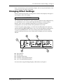
Changing Effect Settings
When you dial up a Program, its Configuration is shown in the display to the right of
the Program’s name. For example:
Vocal Ballad HALL REVERB
The Configuration will either be a single reverb type effect (as in the example above),
or a combination of two or three effects (like Reverb+Delay, or Chorus>Delay>
Reverb). Once you have identified what effects are used in the Program’s
Configuration, you can then find the effect parameters more easily.
To edit a Program’s effect settings, you must first enter Edit mode. This is done by
pressing either the [EDIT/PAGE] button or any one of the [A], [B], [C] or [D] buttons,
as long as the [PROG] button is lit (Note: Pressing these buttons in other modes
performs different functions). Once in Edit mode, the display will look something
like this:
Ê
Ë
Ì
Í
Î
Page Numbers
Selected Page
Parameter Name Strip
Parameter Values and Bar Graphs
A, B, C, D and EDITED Indicators
For more about using the Wedge Display in Edit mode, see Chapter 3.
Wedge Reference Manual
11
Chapter 1 – Your First Session with the Wedge
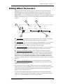
To edit effect parameters:
Ê Press the [PAGE] button to enter Edit mode.
This selects the first page of effect parameters, if you are editing the Program for the first
time. There are usually two or more pages available in Edit mode, depending on the
Program’s Configuration. The exact number of pages available will be indicated by the
numbers illuminated in the bottom-left corner of the display. Repeatedly pressing
[PAGE] cycles through the available pages. The currently selected page will have a box
around its number. Each page contains up to four parameters, which are labeled with
abbreviated names directly above each.
Ë Move one of the [A-D] sliders.
The parameter will flash indicating it is selected for editing. Once you have modified a
parameter’s value, the word “EDITED” will appear directly beneath it. If you change the
value back to its original setting, the word “EDITED” will disappear.
J
Any changes you make are temporary, until you store those changes into memory. If the
Program you are editing is in the Preset bank, you must save the changes you’ve made to a
location in the User bank. If you recall another Program before storing, your changes will be
lost. For more information , see “Storing Edited Programs”, later in this chapter. For more
about editing effects parameters, see Chapter 4.
Using Online Help
The Wedge has built-in online help to assist you in identifying parameter functions
from the display, without having to look things up in this manual. Once you have
accessed Edit mode (see previous section), you can select any of the parameters
shown in the display by pressing the corresponding button ([A], [B], [C] or [D]).
However, by holding one of these buttons for more than one second, the upper
display will provide a more detailed description of the selected parameter.
For example, if we were still editing Preset 18 (see previous page), holding the [D]
button for more then one second would reveal the name of the “D” parameter:
INPUT LOWPASS FILTER
Once the button is released, the display reverts back to normal.
12
Wedge Reference Manual
Your First Session with the Wedge – Chapter 1
Adjusting Effects Mix Levels
Whether a Program contains a single effect or two or three effects, you can adjust
each effect’s mix to obtain a desirable balance between the original, uneffected signal
and each effect’s output. The Mix parameter (or “wet/dry mix”) for each effect is
found along with the other effect parameters in Edit mode. To make things easier, the
Mix parameter has been consistently placed at the far right of the display page (this
corresponds to the [D] button), on the last page of each effect. Since each effect has a
different number of edit pages, the Mix parameter will not always appear on the
same page for each Program. Keep in mind that if a Program uses more than one
effect, each effect will have its own Mix parameter.
Ê Press the [EDIT/PAGE] button to enter Edit mode.
Look at the far right side of the display for the word MIX (or some variation that identifies
a specific effect’s mix parameter; i.e. CMIX = Chorus Mix, RMIX = Reverb Mix, etc.). If
it doesn’t appear, press the [PAGE] button repeatedly until you find it. To be sure the
Mix parameter in the display is the one you want, use the built-in Online Help function
(see previous section) by holding the [D] button for more than one second.
Ë Press the [EDIT/PAGE] button repeatedly until you reach the highest numbered
page available is selected.
Ì Move the [D] slider to edit the Mix parameter.
The parameter will flash indicating it is selected for editing. The Mix parameter’s range
is 000-100å.
Comparing an Edited Program to its
Original Settings
The left side of the display always indicates the currently selected Program. If the
[PROG] button is pressed once while in Edit mode, the currently selected Program’s
name and the Configuration being used both appear in the upper part of the display.
Once a Program has been edited, the Configuration’s name will appear in lower case
letters. With multi-effect Configurations (where there is more than one effect being
used) and only one effect has been edited, only the edited effect’s name will appear
in lower case letters. Example: If using the Configuration ROOM+DELAY and you
have edited only the Delay’s parameters, the display will read “ROOM+delay” if the
[PROG] button is pressed. This indicates that one or more of the Delay’s parameters
have been altered, but the Reverb’s parameters have not been changed.
By pressing the [COMPARE] button, you can temporarily access the original version
of the Program you are editing — that is, the last Program saved to the currently
selected location number. This allows you to compare the differences created by
changing parameters in the edited Program.
While you are in Compare mode, the display will show the previous values and the
[COMPARE] button will light up. You can use the [EDIT/PAGE] button to scroll to
other pages while in Compare mode. Pressing the button again or pressing [PROG]
Wedge Reference Manual
13
Chapter 1 – Your First Session with the Wedge
exits Compare mode; the display will return to its original state and the edited
version of the Program will be restored.
Restoring an Edited Program to its Original
Settings
If you decide to abort the changes you have made to an edited Program, this can be
done in two easy steps:
Ê Press [PROG].
The display will exit Edit mode.
Ë Turn the [VALUE] knob to select a different Program, then turn it back the
opposite direction to re-select the original Program. (Alternately, you can press
the [PROG] button three times.)
This recalls the stored version of the selected Program number, and the Configuration
name in the display returns to all upper case letters. Consequently, any changes you had
made to the Program before turning the [VALUE] knob would be lost. (That is, unless
you stored the edited Program into memory first.)
Bypassing Effects
At any time you can bypass the effects, allowing you to hear the direct signal without
any processing. This can be done by pressing the [BYPASS] button.
J
14
If the Dry Defeat function is on (see previous section) and the BYPASS button is pressed, no
audio will pass through the unit. Similarly, if the Mix on any program is set to 100% wet and
Bypass is pressed, the unit will not have any audio from its outputs.
Wedge Reference Manual
Your First Session with the Wedge – Chapter 1
Storing and Naming Edited Programs
Once you are satisfied with the changes you have made to an edited Program, or are
creating a new Program from scratch, you will need to store your edited Program
back into memory. The Wedge will store the currently selected Program in nonvolatile memory (which is backed-up when the unit is turned off). If you edit a
Program, the changes you made will still be there the next time you switch on the
unit, even if you hadn’t stored the edited Program into memory yet. However, if you
select another Program from memory before storing the edited Program, your
changes will be lost forever.
J
Although the Wedge has two banks (Preset and User), you can only store Programs in the
User bank.
To store an edited Program:
Ê Press [STORE].
The [STORE] button will flash, and the display will read:
Store XXX (nnnnnnnnnnnn)?
…whereas XXX is a Program location number from 00—127 in the User bank, and
nnnnnnnnnnnn is the Program’s name.
Ë Use the [VALUE] knob to select which location (00—127) you wish to store the
selected Program into.
You can only store Programs into the User bank. If you select a Program from the Preset
bank and store it, you will automatically be taken into the User bank.
Ì If desired, change the Program’s name by pressing [A/NAME].
This moves the cursor from the location number field to the first character in the
Program’s name. Turn the [VALUE] knob to scroll through the list of available
characters. Use the [C/<] and [D/>] buttons to move the cursor’s position left and right,
respectively. If you need to move the cursor back to the Program number field to select a
different location to store to, press [B/ESC].
Note: To abort this operation — and thereby not store the edited Program — simply
press any other button except [STORE].
Í Press [STORE] again.
The [STORE] button’s LED will momentarily flash quickly, while the display reads:
Prog nnnnnnnnnnnn Stored!
…whereby nnnnnnnnnnnn is the Program’s name. The [STORE] button will turn off
and the display will revert to wherever it was before [STORE] was pressed for the first
time.
Wedge Reference Manual
15
Chapter 1 – Your First Session with the Wedge
16
Wedge Reference Manual
Connections – Chapter 2
CHAPTER 2
CONNECTIONS
AC Power Hookup
The Wedge comes with a power adapter suitable for the voltage of the country it is
shipped to (either 110 or 220V, 50 or 60 Hz).
With the Wedge off, plug the round end of the supplied power adapter cord into
Wedge’s [POWER] socket and the male (plug) end into a source of AC power. It’s
good practice to not turn the Wedge on until all other cables are hooked up.
J
Alesis cannot be responsible for problems caused by using the Wedge or any associated
equipment with improper AC wiring.
Line Conditioners and Protectors
Although the Wedge is designed to tolerate typical voltage variations, in today’s
world the voltage coming from the AC line may contain spikes or transients that can
possibly stress your gear and, over time, cause a failure. There are three main ways
to protect against this, listed in ascending order of cost and complexity:
•
Line spike/surge protectors. Relatively inexpensive, these are designed to
protect against strong surges and spikes, acting somewhat like fuses in that they
need to be replaced if they’ve been hit by an extremely strong spike.
•
Line filters. These generally combine spike/surge protection with filters that
remove some line noise (dimmer hash, transients from other appliances, etc.).
•
Uninterruptible power supply (UPS). This is the most sophisticated option. A
UPS provides power even if the AC power line fails completely. Intended for
computer applications, a UPS allows you to complete an orderly shutdown of a
computer system in the event of a power outage, and the isolation it provides
from the power line minimizes all forms of interference—spikes, noise, etc.
Audio Connections
The connections between the Wedge and your studio are your music’s lifeline, so
use only high quality cables. These should be low-capacitance shielded cables with a
stranded (not solid) internal conductor and a low-resistance shield. Although
quality cables cost more, they do make a difference. Route cables to the Wedge
correctly by observing the following precautions:
•
Do not bundle audio cables with AC power cords.
•
Avoid running audio cables near sources of electromagnetic interference such as
transformers, monitors, computers, etc.
Wedge Reference Manual
17
Chapter 2 – Connections
•
•
Never unplug a cable by pulling on the wire itself. Always unplug by firmly
grasping the body of the plug and pulling directly outward.
Do not place cables where they can be stepped on. Stepping on a cable may not
cause immediate damage, but it can compress the insulation between the center
conductor and shield (degrading performance), or reduce the cable’s reliability.
•
Avoid twisting the cable or having it make sharp, right angle turns.
•
Although Alesis does not endorse any specific product, chemicals such as
Tweek and Cramolin, when applied to electrical connectors, are claimed to
improve the electrical contact between connectors.
Typical Applications
The audio inputs and outputs are typically used in one of three ways:
•
from one or two aux send outputs of a mixer, and back to the effect return
inputs of the mixer; or,
•
from a line-level instrument (like a guitar or keyboard with either a mono or
stereo output), and out to an amplifier or mixer input; or,
•
from the stereo buss outputs of a mixer to a mix-down tape machine or
amplifier.
When used with a mono source, the Wedge is placed between the source and the
mixer/amplifier. Although the source may be mono, both the [LEFT] and [RIGHT]
outputs can be connected to the inputs of a mixer/amplifier if stereo processing
effects are desired.
Alternatively, you could use the inserts on your mixer to “patch in” only the left or
right channel of the Wedge. If using the effect sends of a mixer, you have the
advantage of sending any of the mixer’s input channels to the Wedge’s input(s), and
have control over the level of each channel being sent.
These applications are outlined and illustrated in detail on the following pages.
Input Jack Wiring
The Wedge’s [LEFT] INPUT jack is normalled to the [RIGHT] INPUT. This means
that if you only connect a single mono cable to the [LEFT] INPUT jack, it will also be
routed to the [RIGHT] INPUT. However, if anything is connected to the [RIGHT]
INPUT jack, this normalized connection will be broken; therefore the [LEFT] INPUT
jack feeds only the [LEFT] INPUT, and the [RIGHT] INPUT jack feeds only the
[RIGHT] INPUT.
18
Wedge Reference Manual
Connections – Chapter 2
Balanced Operation
The Wedge features balanced TRS inputs and outputs. This allows it to be used with
professional consoles and other balanced equipment. You may need to purchase an
XLR to TRS 1/4” cable or adaptor, depending on the jacks used on the connecting
equipment.
The Wedge uses Servo Balancing on its inputs. This means that you can plug in
either a balanced (3-connector) or unbalanced (2-connector) signal without changing
the input level setting.
Alternatively, if your console uses balanced 1/4” TRS connectors for the effects
sends and returns (like the Alesis Studio 32) you should use “stereo phone cord”
TRS balanced cables for connection to the Wedge.
Interfacing Directly with Instruments
J
When connecting audio cables and/or turning power on and off, make sure that all devices in
your system are turned off and the volume controls are turned down.
The Wedge has two 1/4” balanced/unbalanced inputsand two 1/4” balanced/
unbalanced outputs. These provide three different audio hookup options:
•
Mono: Connect an audio cable to the [LEFT] INPUT of the Wedge from a mono
source, and another cable from the [LEFT] output of the Wedge to an
amplification system or mixer input.
Wedge Reference Manual
19
Chapter 2 – Connections
•
Mono In, Stereo Out: While still using a mono input, you could connect two
mono cords to the [LEFT] and [RIGHT] outputs of the Wedge to a stereo
amplification system or two mixer inputs.
•
Stereo: Connect two cables to the [LEFT] and [RIGHT] INPUTS of the Wedge
from a stereo source , and two other mono cords from the [LEFT] and [RIGHT]
OUTPUTS of the Wedge to a stereo amplification system or two mixer inputs.
Interfacing to a Mixing Console
The Wedge handles mono or stereo sends at all system levels. The input circuitry of
the Wedge can easily handle professional +4 dBu levels (+20 dBu peaks), while
having enough input and output gain to interface with the lower -10 dBV signal
levels of home and project recording studios.
The Wedge may be connected to a mixing console in several different ways. It can
be used to effect several instruments at once by using the auxiliary send and return
controls of the mixer. Another method of interfacing is to connect the unit directly
to the insert send and return patch points of the channel that is to be effected. Still
another way of interfacing the Wedge to a mixer or recording console would be inline across the output of your mixing console. This last setup would be used only if
you needed to affect the entire mix.
20
Wedge Reference Manual
Connections – Chapter 2
Using Aux Sends
Generally, mixing consoles provide two types of auxiliary sends: pre-fader sends for
creating a cue (headphone) mix, and individual, post-fader effect sends. Typically, if
a mixer has more than two sends per channel (4, 6 or 8, perhaps), the first two sends
are reserved for the cue sends, while the remaining sends are used to feed effects,
such as the Wedge. If you are using a mixer with more than two sends, connect the
Wedge using post-fader sends.
Using a mixer’s aux sends poses a distinct advantage: each channel has its own level
control feeding the aux output (and eventually the Wedge input). This allows you to
make a mix of any channels you want to go to the effects by using the individual
channels’ aux send levels on the mixer. Most consoles also have aux master controls,
which set the overall level of each aux output. Coming back from the Wedge’s
outputs into the mixer, you have two options:
•
•
connecting to dedicated return inputs, or
connecting to channel inputs.
The former is good if your mixer provides dedicated inputs (called returns) for
effect devices like the Wedge. If your mixer does not have these, or you have
already used them all, consider connecting the Wedge to channel inputs (if there are
any remaining). This option also allows you to pan and EQ the effects, or to send
them to the headphone or monitor mix.
No matter where you connect the output of the Wedge into the mixer, you are in
control of the balance between the mixer’s channel inputs (the uneffected signal
being routed to the aux sends and the Mix), and the effect returns coming from the
Wedge. The effect returns generally should only contain effected signal, and not
have any uneffected signal mixed with it (since these two signals are blended
together at the mixer). Therefore, it may be necessary to modify the mix of each
channel in the Program you are using so that only effected signal is present at the
Wedge’s outputs. This can be done in two ways:
•
•
Set each effect’s Mix parameters to 100% (wet signal only)
Turn on the Dry Defeat function.
For more information about Dry Defeat, see Chapter 1.
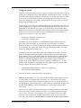
Mono In - Stereo Out: If you only want to feed the Wedge a mono input, but wish
to connect both of its outputs back to the mixer, you will need three 1/4" audio
cables. Connect a balanced or unbalanced cable(s) from an aux send of the mixer to
the [LEFT] input of the Wedge, and two other balanced or unbalanced cable(s) from
the [LEFT] and [RIGHT] outputs of the Wedge to a stereo effect return or other
mixer input.
For most of its programs, especially reverb programs, the Wedge synthesizes a stereo image
from a single input, emulating the effect of a single source reflecting off the left and right
sides of a room. This Mono In hookup allows you to get the benefit of these stereo effects,
while using only one effect send. But other dual/parallel programs are best used with a
stereo input, described below. Use this Mono In - Stereo Out hookup only if you don't
Wedge Reference Manual
21
Chapter 2 – Connections
have enough Aux sends from your mixer to use the Stereo In hookup described
below.
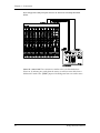
Stereo In - Stereo Out: This connection is similar to the one described above.
However, by utilizing two sends from the mixer, we add one more cable from a
different aux send to the [RIGHT] input of the Wedge and can now send a stereo
22
Wedge Reference Manual
Connections – Chapter 2
signal to the Wedge’s inputs.
Certain Wedge programs allow you to use the left and right inputs separately, creating a
separate effect for each input. The DELAY:DELAY, CHORUS:CHORUS, ROOM+HALL,
ROOM+PLATE configurations are examples of this kind of multieffect that, essentially,
allow you to use the Wedge as two independent mono or stereo effect units. For this reason,
we recommend using the Stereo In - Stereo Out hookup whenever possible to get the
most out of the Wedge.
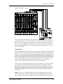
Using Inserts
By using individual channel inserts, you can dedicate the Wedge to a specific channel
(or pair of channels) on the mixer. The Insert connections on the back of the mixer
provide a way of “inserting” external processing equipment into the signal path. The
insert occurs after the input amplifier, and before the main fader; essentially it is the
same as connecting the source (instrument or microphone) into the Wedge before the
mixer’s channel input. However, some mixing console’s inserts come after the EQ
section, and may therefore be different from the original signal. If nothing is
connected to the channel’s Insert jack, the signal is not routed there.
Usually, insert connections require a special, stereo-splitting Y-cord to be connected
(one stereo plug provides both send and return while two mono plugs connect
separately to an input and output). Stereo Plugs are known as TRS connectors (tipring-sleeve). The tip of the stereo plug carries the send or output of the insert jack,
while the ring brings back the return. The sleeve represents a common ground for
both signals.
Mono: Connect a 1/4" TRS (tip-ring-sleeve) Y-cable to the Insert jack of a single
channel on a mixing console. Connect the other end of the cable (which splits into
two, 1/4" mono connectors) to the [LEFT] input and [LEFT] output, respectively. If
Wedge Reference Manual
23
Chapter 2 – Connections
you do not hear any audio after making these connections, swap the input and
output cables at the Wedge, as these may be wired backwards. If the cable is colorcoded, usually the red jack represents the send (which connects to the Wedge’s
input) and black is the return (which connects to the output).
Stereo. If a stereo instrument (such as a keyboard or sampler) is con-nected to two
separate channels of a mixing console, you will need two 1/4" TRS cables, one for each
channel. The connection is made in a similar fashion as described above. This hookup
is especially useful for adding ambience with the Stereo Room configuration.
24
Wedge Reference Manual
Connections – Chapter 2
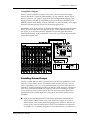
Using Main Outputs
When you want to effect everything on the mixer, you can connect the Wedge
between the mixer’s outputs and the amplifier’s or tape machine’s inputs. This is
done by using two 1/4" cables to connect the Left and Right Main Outputs of the
mixing console to the [LEFT] and [RIGHT] inputs of the Wedge. The [LEFT] and
[RIGHT] outputs of the Wedge are then connected to a stereo amplifier, or two input
channels of another mixing console (for sub-mixing applications).
Remember to turn off Dry Defeat. In the Insert and Main Output hookups described
above, the entire signal passes through the Wedge, with no alternate path for the
dry signal. If you use these methods, remember to turn the global Dry Defeat
feature (UTIL menu p. 1, [D] control) OFF. If it is ON, you will hear too much effect
and no direct signal at all.
Avoiding Ground Loops
In today’s studio there are many opportunities for ground loop problems to occur.
These show up as hums, buzzes or sometimes radio reception and can occur if a
piece of equipment “sees” two or more different paths to ground. While there are
methods to virtually eliminate ground loops and stray radio frequency interference,
most of the professional methods are expensive and involve installing a separate
power source just for the sound system. Here are some easy helpful hints that a
professional studio installer might use to keep those stray hums and buzzes to a
minimum.
Ê KEEP ALL ELECTRONICS OF THE SOUND SYSTEM ON THE SAME AC
ELECTRICAL CIRCUIT. Most stray hums and buzzes happen as a result of
different parts of the sound system being plugged into outlets of different AC
circuits. If any noise generating devices such as air conditioners, refrigerators,
neon lights, etc., are already plugged into one of these circuits, you then have a
Wedge Reference Manual
25
Chapter 2 – Connections
perfect condition for stray buzzes. Since most electronic devices of a sound
system don’t require a lot of current (except for power amplifiers), it’s usually
safe to run a multi-outlet box or two from a SINGLE wall outlet and plug in all
of the components of your system there.
Ë KEEP AUDIO WIRING AS FAR AWAY FROM AC WIRING AS POSSIBLE.
Many hums come from audio cabling being too near AC wiring. If a hum
occurs, try moving the audio wiring around to see if the hum ceases or
diminishes. If it’s not possible to separate the audio and AC wiring in some
instances, make sure that the audio wires don’t run parallel to any AC wire
(they should only cross at right angles, if possible).
Ì TO ELIMINATE HUM IF THE ABOVE HAS FAILED:
A) Disconnect the power from all outboard devices and tape machines except
for the mixer and control room monitor power amp.
B) Plug in each tape machine and outboard effects device one at a time. If
possible, flip the polarity of the plug of each device (turn it around in the
socket) until the quietest position is found.
C) Make sure that all of the audio cables are in good working order. Cables
with a detached ground wire will cause a very loud hum!!
D) Keep all cables as short as possible, especially in unbalanced circuits.
If the basic experiments don’t uncover the source of the problem, consult your
dealer or technician trained in proper studio grounding techniques. In some cases, a
“star grounding” scheme must be used, with the mixer at the center of the star
providing the shield ground on telescoping shields, which do NOT connect to the
chassis ground of other equipment in the system.
MIDI Connections
MIDI (Musical Instrument Digital Interface) is an internationally-accepted protocol
that allows musical-related data to be conveyed from one device to another. The
MIDI connections on the Wedge provide four different functions:
•
To recall Programs using MIDI program change messages
•
To control (modulate) parameters inside the Wedge in realtime via MIDI
controllers (example: A keyboard’s mod wheel, or pedals, etc.)
•
To record and play back edits from the Wedge front panel into a sequencer for
playback during a track
•
To send and receive Sysex (System Exclusive) dumps of individual programs or
the entire bank of programs for storage and retrieval purposes
•
To pass-on MIDI information thru the Wedge to another MIDI device.
To connect the Wedge’s MIDI ports to another MIDI device:
Ê Connect a MIDI cable from the Wedge’s MIDI [IN] connector to the other MIDI
device’s MIDI OUT connector.
26
Wedge Reference Manual
Connections – Chapter 2
Ë Connect another MIDI cable from the Wedge’s MIDI [OUT/THRU] connector to
the MIDI IN connector of the other MIDI device.
Note: It is not necessary to follow step 2 if you intend to only send information to the
Wedge, and do not need to receive information back from it. Example: If you only
want to be able to recall Programs using MIDI program change messages, there is
no need to connect a cable to the Wedge’s [OUT/THRU] connector.
For more information about MIDI and Modulation, refer to Chapter 6.
Wedge Reference Manual
27
Description of Controls – Chapter 3
CHAPTER 3
DESCRIPTION OF CONTROLS
Front Panel
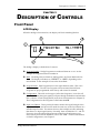
LCD Display
When the Wedge is first turned on, the display will look something like this:
The Wedge’s display is divided into 5 sections:
Ê Program Number. Wedge Programs are numbered from 00 to 127. In this
example the Program selected is number 01.
Ë Bank. The Wedge has two Banks of 128 Programs: the Preset Bank and User
Bank. The display will either say “PRESET” or “USER”, depending on the
current Bank. In this example we are in the Preset Bank.
Ì Program Name. Each Program has its own eight character name. This one is
called Medium Hall. The 128 User Programs can be renamed; the 128 Preset
Programs are pre-programmed at the factory and cannot be renamed.
Í Configuration. This tells us what type of effect this Program is. It can also tell
you the order that the input signal(s) will pass through multieffects and whether
this is a Stereo or Dual Configuration (more about Configurations in Chapter 5).
The Configuration for this Program is called HALL REVERB.
Î Input Level Meters. These peak style meters monitor the signal strength of the
unprocessed inputs, and are used in much the same way as the level meters on a
standard tape recorder. The meters shown in this example are idle, indicating
that there is no input signal activity. Normally, these are labeled as “L” and “R”.
However, when the selected Program uses a Dual type Configuration (two
mono effects), these will be labeled as “CH1” and “CH2”. For more information
on Dual Configurations, see Chapter 5.
Wedge Reference Manual
27
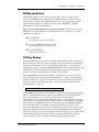
Chapter 3 – Description of Controls
When editing a Program, the display changes slightly to indicate additional
information. Once in Edit mode, the display will look something like this:
Ê Page Numbers. Depending on the Configuration, there will be up to six pages
available in Edit mode. In this example, only five pages are available.
Ë Selected Page. The currently selected page will be indicated by a box around its
number. In this example, page 1 is currently selected. Each time you press the
[EDIT/PAGE] button, the display will advance to the next page.
Ì Parameter Name Strip. Each page in Edit mode contains up to four parameters.
whose names will appear at the top of the display, above their value settings.
Í Parameter Values and Bar Graphs. Each parameter in the selected page is
shown with both a numerical value and a bargraph. As you adjust a parameter,
both its numerical value and bargraph will change in relation to the Value
Slider’s position. The type of units will be shown as well (dB, mSec, kHz, etc.).
Î A, B, C, D and EDITED Indicators. Each parameter in the selected page is
designated by a letter (A, B, C or D), which indicates which slider ([A], [B], [C]
or [D]) should be moved to edit the desired parameter. Once a parameter has
been edited, the word “EDITED” will appear below it.
VALUE Knob
The [VALUE] knob may be used to raise or lower the selected value in the display by
turning either clockwise or counterclockwise. If the [PROG] button is lit, turning the
[VALUE] knob lets you scroll through the internal Programs. When an effect
parameter is selected (flashing in the display), turning the [VALUE] knob will alter
its value. Using the [VALUE] knob instead of the sliders can be useful if you’re
trying to enter a specific value.
EDIT/PAGE Button
The [EDIT/PAGE] button is used in Program mode to advance through the available
Edit pages. When [EDIT/PAGE] is pressed in Program mode, the Program’s
parameters will be displayed for editing. The total number of pages will appear in
28
Wedge Reference Manual
Description of Controls – Chapter 3
the lower left corner of the display, and the currently selected page will have a box
around it. Each time [EDIT/PAGE] is pressed it will advance to the next page; when
the last page is reached it cycles back to the first page.
TAP/AUDITION Button
The [TAP/AUDITION] button has three functions:
•
When in Program mode, this button activates the Impulse Audition™, a single
sample impulse, through the effect. The Impulse is a scientifically-designed
sound that produces every frequency in the audio spectrum for one sample
(1/48,000 of a second). This allows you to hear subtle differences when moving
reverb parameters and to reveal problems in a program before they end up on
your mix.
•
When editing a delay program, the [TAP/AUDITION] button acts as a tap tempo
control. Press the button twice in the tempo of the song and your delay time will
change to follow the tempo. You can even hold the button down to use the input
signal as a tap tempo source.
•
When you hold the [I/O] button and press [TAP/AUDITION], the unit will go
into Auto Level Sensing mode (see page 9, “Automatic Input Level Settings”).
A/B/C/D (NAME/ESC/</>) Buttons
The [A], [B], [C] and [D] buttons can be used in Program mode to select parameters
for editing with the [VALUE] wheel on the current page. When in Program mode,
pressing any of the [A], [B], [C] and [D] buttons will select the corresponding
parameter (A, B, C, or D) in the display, and the selected parameter will flash. On
parameters with only two possible values (On/Off, Fast/Slow), pressing the [A],
[B], [C] and [D] buttons will toggle the parameter value.
When selecting a parameter, if the corresponding [A], [B], [C] or [D] button is held
for longer than one second, a brief description of that parameter will appear in the
display. This is the Wedge’s built-in online help system. If there is no corresponding
parameter for one or more of the [A], [B], [C] and [D] buttons in a particular page, it
will be indicated in the display when the button is pushed. For example, if you were
editing an effect in page one which did not have an “A” parameter displayed and
the [A] button was pressed, the message “NO "A" PARAM ON PAGE 1” would briefly
appear.
The [A], [B], [C] and [D] buttons also allow you to name Programs. When in Store
mode ([STORE] button flashing), the [A], [B], [C] and [D] buttons can be used to
enter the Program’s name. Pressing [A/NAME] moves the cursor in the display to the
first character of the Program’s name. The [C/<] and [D/>] buttons move the cursor
left and right, respectively, through the eight character fields of the Program’s name.
To move the cursor back to the Program location number, press [B/ESC].
A/B/C/D Sliders
Wedge Reference Manual
29
Chapter 3 – Description of Controls
The [A], [B], [C] and [D] Sliders are used to edit parameters in Edit mode. The
quickest way to edit a program on the Wedge is to press Edit and start moving the
sliders. You don’t have to select a parameter before moving the slider, just grab it
and the parameter will jump to the new value. The Sliders can also be used in the
Utility and Input/Output pages.
30
Wedge Reference Manual
Description of Controls – Chapter 3
PROGram Button
The [PROG] button is used to select Program mode. When Program mode is
selected, the [PROG] button will be lit. The [VALUE] knob may then be used to
scroll through programs. The [PROG] button is also used to toggle between the
Preset and User banks. The display will show either "PRESET" or "USER"
indicating the currently selected bank.
Tip: To select programs that are far apart more quickly, it may be faster to press
[PROG] to switch between the Preset and User banks. For example, to go from
PRESET 00 to USER 127:
Ê Press [PROG].
The program will switch to USER 00.
Ë Turn the [VALUE] knob back one click.
The program will switch to PRESET 127.
Ì Press [PROG] again.
USER 127 will be selected.
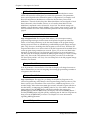
UTILity Button
When the [UTIL] button is pressed, it will light and the display will be showing the
last selected page. There are a total of 5 Utility pages, as indicated by the numbers 1
through 5 which appear in the lower-left corner of the display. You can advance
through each page by pressing the [EDIT/PAGE] button. The currently selected page
number will have a box around it. The Utility pages provide various functions
which are not stored with the Effects Programs. These include:
Page 1: Dry Defeat. The Dry Defeat function, when enabled, removes the direct
(dry) signal globally from all Programs simultaneously, so that only effected (wet)
signal is routed to the outputs. This function is perfect for connecting the Wedge to
a mixing console’s aux sends and returns. Use the [D] button to toggle the Dry
Defeat function on and off.
Dry Defeat
Page 2: MIDI. Three functions are available in Utility page 2, all dealing with MIDI.
The first is MIDI Channel (Chan), which can be edited by moving the [B] slider to
select a channel from 1 to 16, or to 00 for Omni mode (all 16 channels
simultaneously). The next function, MIDI-Thru (Thru), can be toggled on and off by
pressing [C] or moving the [C] slider. When turned on, the Wedge allows the MIDI
data received at the [MIDI IN] port to be passed through to the [MIDI OUT/THRU]
port. The third function is Program Change Enable (PChg). This can be set by
moving the [D] slider to either Off, On or Table. When set to off, the Wedge ignores
program change messages. When set to on, incoming MIDI program change and
bank select messages received on the same channel the Wedge is set to will recall the
same numbered Program. When set to table, the Wedge will use the Program
Change Table (see below) to remap incoming program change messages.
Wedge Reference Manual
31
Chapter 3 – Description of Controls
MIDI: Chan Thru PChg
Page 3: Modulators. This is where you select the two MIDI modulation sources
which will be used for all Programs to control their parameters. The parameters
these control depend on the selected Program’s Configuration. For example, in all
Reverb Configurations, Modulator X controls the Reverb Decay Time, while
Modulator Y controls the Wet/Dry Mix. Either Modulator can be assigned to: Pitch
Bend, Aftertouch, Note Number, Velocity or a Controller from 000–119. Each
Modulator’s amplitude can be set between -99 and +99. The default settings are:
Mod#X = 001 (modulation wheel), Mod#Y = 007 (volume), Amp X and Y = 000. For
more information and a list of the modulated parameters in each Configuration, see
page 69.
Mod#X AmpX Mod#Y AmpY
Page 4: Program Table. The Program Table allows you to intercept incoming
program change messages and have them recall specific Programs (in either the
Preset or User bank) which may not be the same number as the program change
message received. There are 128 different possible MIDI program change messages
(000 – 127). However, the Wedge has 256 Programs to choose from. Therefore, the
Program Table allows us to choose which of the 256 Programs will be recalled when
certain program change numbers are received. [Note: you can also use Bank Select
messages to select Preset or User Programs, see Chapter 6 for more information.]
The first value in the display indicates the MIDI program change you wish to remap
(000—127). The second value indicates the Program you wish to be recalled (00—
127 Preset (Pset) and 00—127 User). You can remap each of the 128 program change
numbers, if so desired.
Program Tbl: MIDI User
If the D parameter is lowered below User 000, the display will change from User to
Pset to indicate that you are now assigning an incoming program change number to
a Program in the Preset bank.
Program Tbl: MIDI Pset
Page 5: Send Sysex. This page lets you dump out all 128 User Programs or the
current Program being used/edited, or the Program Change Table (see above). The
data is sent as Sysex information. This can be sent to a MIDI storage device, or to
another Wedge. Select either All or Buffer (the currently selected Program which is in
the edit buffer), or Table using the [VALUE] wheel or any of the sliders. When this
page is selected, the [STORE] button will flash to indicate that pressing the
[STORE] button starts the MIDI dump. The display will read “Transmitting Sys Ex...”
and the [STORE] button will flash quickly, indicating that all 128 User Programs are
being sent out the [MIDI OUT] connector. See Chapter 6 for more information
regarding MIDI applications.
Send MIDI Sysex: All
32
Wedge Reference Manual
Description of Controls – Chapter 3
I/O Button
The [I/O] Button is used to view and adjust the input and output levels. When this
button is pressed, the display will show both the current input and output settings.
The [A], [B], [C] and [D] sliders can then be used to adjust the level settings.
InL InR OutL OutR
In the range from a setting of 040 to 100, each number has a value of approximately
0.3 dB, so each jump of ten will change the input or output level by slightly over 3
decibels. Below 040, the taper increases to approximately 6 dB per ten.
Auto Level
When both the [I/O] and [TAP/AUDITION] buttons are pressed simultaneously, the
Auto Level function is activated. This function “listens” to the signal present at the
input jacks and sets the input level to an appropriate value. The Auto Level function
listens for a period of five seconds. During this time, you should feed signal to the
Wedge’s inputs (i.e. play your guitar or keyboard, or playback tape).
To cancel the Auto Level function once it has been engaged, press any button on the
front panel.
Wedge Reference Manual
33
Chapter 3 – Description of Controls
STORE Button
The [STORE] button is used to permanently keep changes you make to a Program,
or to copy a Program to a different location. When pressed for the first time, the
[STORE] button will flash, to indicate that it is prepared to store the current
Program. At this point, you can choose to alter the Program’s name, and/or choose
a different location to store the Program into. When you’re ready to store, press the
[STORE] button a second time.
To store an edited Program:
Ê Press [STORE].
The [STORE] button will flash, and the display will read:
Save XXX (nnnnnnnnnnnn)?
…whereas XXX is a Program location number from 00—127 in the User bank, and
nnnnnnnnnnnn is the Program’s name.
Ë Use the [VALUE] knob to select which location (00—127) you wish to store the
selected Program into.
You can only store Programs into the User bank. If you select a Program from the
Preset bank and store it, you will automatically be taken into the User bank.
Ì If desired, change the Program’s name.
See the section on the “A/B/C/D Buttons”, earlier in this chapter.
Í Press [STORE] again.
The [STORE] button’s LED will momentarily flash quickly, while the display reads:
Prog nnnnnnnnnnnn Stored!
…whereby nnnnnnnnnnnn is the Program’s name. The [STORE] button will turn off
and the display will revert to wherever it was before [STORE] was pressed for the first
time.
COMPARE Button
The [COMPARE] button allows you to review what the Program sounded like
before you made any edits. This allows you to page through a program’s
parameters and see the previous values of any of your edits. You exit Compare
mode by pressing the [COMPARE] or [PROGRAM] button. Any edited parameters
will have the word “EDITED” next to the new value.
BYPASS Button
The [BYPASS] button switches the Wedge into Bypass mode. This mode allows you
to hear the “dry” signal without effects. If Dry Defeat (see UTIL mode, above) is
turned off and the Wedge is in Bypass mode, the input signal will be passed
through without effects. If Dry Defeat is turned on and Bypass is on, no signal will
pass through the unit.
34
Wedge Reference Manual
Description of Controls – Chapter 3
Rear Panel
POWER Switch
The [POWER] switch turns the AC power to the unit ON (in) or OFF (out).
Power
This is a plug for connecting the +9VAC power supply (supplied). The power
supply is then connected to an AC outlet delivering a nominal 120VAC. The correct
power supply must be used AT ALL TIMES. Any other power supply might create
a fire risk and/or permanently damage your unit. This damage would NOT be
covered under your warranty.
MIDI In
This is a 5 pin DIN standard MIDI plug which connects to any MIDI compatible
equipment such as a MIDI sequencer that will send program changes and controller
information to the unit.
MIDI Out/Thru
This is a 5 pin DIN standard MIDI plug which connects to any MIDI compatible
equipment such as a keyboard or another effects device. It is provided for sending
system exclusive commands for storing programs. It also relays all messages
received on the [MIDI IN] if MIDI THRU is enabled. The MIDI THRU function is
found in the UTILity mode (see “UTILity Button”, earlier in this chapter).
Input (Left & Right)
These are balanced 1/4" phone jacks which connect to sources such as the effects
sends of mixing consoles. They may be used with nominal input levels from -10dBV
(guitar level) to +4dBu.
For mono applications, use the [LEFT] input. The [LEFT] input jack is normalled to
the [RIGHT] jack. This means that when nothing is plugged into the [RIGHT] input
jack, the signal present at the [LEFT] input will be routed to the [RIGHT] as well.
Output (Left & Right)
These are balanced 1/4" phone jacks which connect to devices such as the effect
returns on a mixing console. For mono applications, use the [LEFT] output.
Wedge Reference Manual
35
Editing Programs – Chapter 4
CHAPTER 4
EDITING PROGRAMS
Selecting A Configuration
A Configuration is made up of one or more effects. Each of the internal Programs of
the Wedge use one Configuration. When you want to create your own Program, the
first thing you must decide is which Configuration you wish to use. Then you need
to locate a Program that already uses this Configuration. For example, if you want
to create a new Program using the Hall Reverb Configuration, first locate an existing
Program that already uses the Hall Reverb Configuration. Then store this Program
into a location in the User bank. Once this is done, you can freely edit the new
Program, storing changes as you like, without affecting the original Program you
selected.
Note: The last 28 Programs in the Preset bank (100-127) each use one of the 28
Configurations. This makes it easy for you to locate the Configuration you are
looking for. Also, the last 28 Programs in the User bank (100-127) have been left
blank so you have some place to store your new Programs into.
To select a Configuration:
Ê Press [PROG]. Use the [VALUE] knob to select a Program which uses the
Configuration you want to use.
The display shows each Program’s name on the left and Configuration type on the right:
Medium Hall HALL REVERB
Ë Press [STORE].
The [STORE]button will flash.
Ì Turn the [VALUE] knob to select a Program location in the User bank to store
J
(copy) this Program into.
This will overwrite whatever Program was previously stored in that Program location.
Í Press [STORE] again.
The [STORE] button’s LED will briefly flash, while the display reads:
Prog nnnnnnnnnnnn Stored!
…whereby nnnnnnnnnnnn is the Program’s name. The [STORE] button will turn off
and the display will revert to Program mode ([PROG] button lit).
J
If the Program you select is in the Preset bank, the above would result in storing the
Program in the User bank, using the same number location. Example: If you selected Preset
24 and stored it, the Program would be stored into User 24. This is because the Preset
Programs cannot be permanently changed.
Wedge Reference Manual
35
Chapter 4 – Editing Programs
Now you can start editing the Program’s parameters, and having some real fun!
36
Wedge Reference Manual
Editing Programs – Chapter 4
Editing Effect Parameters
Editing Programs is only possible while in Program mode. This means that the
[PROG] button must be lit. If the [PROG] button is not lit, press it now. From
Program mode, you can edit the currently selected Program by pressing either
[EDIT/PAGE] or any of the [A], [B], [C] or [D] buttons. Upon entering Edit mode, the
display will change to show you up to four parameters associated with the selected
Program.
3
4
1
18
Decay
PRESET
PAGE 1 2 3 4 5
2
LPF
650msec 2.8KHz
A
B
L
EDITED
PDly
PMix
150msec 000%
C
D
R
5
Ê Page Numbers. Depending on the Configuration, there will be up to six pages
available in Edit mode. In this example, only five pages are available.
Ë Selected Page. The currently selected page will be indicated by a box around its
number. In this example, page 1 is currently selected. Each time you press the
[EDIT/PAGE] button, the display will advance to the next page.
Ì Parameter Name Strip. Each page in Edit mode contains up to four parameters
whose names will appear at the top of the display, above their value settings.
Í Parameter Values and Bar Graphs. Each parameter in the selected page is
shown with both a numerical value and a bargraph. When a parameter is selected
for editing, its value will flash in the display. As you adjust a parameter, both its
numerical value and bargraph will change in relation to the slider’s position. For
finer control, you can also adjust the parameter using the [VALUE] wheel when a
parameter is selected. The type of units a parameter uses will be shown as well (dB,
kHz, etc.).
Î A, B, C, D and EDITED Indicators. Each parameter in the selected page is
designated by a letter (A, B, C or D). Once a parameter has been edited, the word
“EDITED” will appear below it.
If you decide you want to select a different Program, you can always get back to
Program mode by pressing [PROG] again. However, if you select another Program
after making changes and without storing the Program back into memory, the
changes you have made will be lost.
To make your changes to the Program permanent, you must store the Program
somewhere in the User bank. If the Program is already in the Preset bank and you
store it, you will automatically be taken into the User bank.
Wedge Reference Manual
37
Chapter 4 – Editing Programs
Moving Through Pages
Once in Edit mode, there will be multiple pages available. The total number of pages
depends on which Configuration the Program uses, and will be indicated by the
numbers appearing in the lower left corner of the display. The [EDIT/PAGE] button
is used to advance through the available pages of effect parameters. The currently
selected page will have a box around it in the display.
Using the A/B/C/D Buttons
The [A], [B], [C] and [D] buttons are used to select parameters in the display for
editing. There are never more than four parameters in the display at any time. Each
parameter corresponds to one of the [A], [B], [C] or [D] buttons. To select a
parameter, press the button associated with its position in the display or move its
fader. Once pressed, the selected parameter will flash in the display. There are three
ways to edit parameters on the Wedge:
•
•
•
Move one of the [A], [B], [C] or [D] sliders
Press one of the [A], [B], [C] or [D] buttons, then turn the [VALUE] wheel
On parameters where you are switching between two possible values (i.e. Lezlie
Speed Slow/Fast) simply pressing one of the [A], [B], [C] or [D] buttons will
switch the value.
Using Online Help
The Wedge has built-in online help to assist you in identifying parameter functions
from the display, without having to look things up in this manual. Once you have
accessed Edit mode (see previous section), you can select any of the parameters
shown in the display by pressing the corresponding button ([A], [B], [C] or [D]).
However, by holding one of these buttons for more than one second, the upper
display will provide a more detailed description of the selected parameter.
Special Cases
Most of the time, a single parameter is represented by a single value in the display.
However, in the case of the Delay Time parameter, where the range is quite wide, it
is helpful to be able to edit different parts of the overall value. In other words, think
how long it takes to scroll from 1 to 5499 ms using 1 millisecond increments.
Except for the “smaller” delays used in the Multi Chain and Dual Mono
Configurations, the Delay Time value is broken down into three parameters: 100ms,
10ms and 1ms. This allows you to adjust the hundredths, tenths and individual
milliseconds individually. Example: In the case of the Mono Delay Configuration, the
Edit mode page 1 display will look like this:
38
Wedge Reference Manual
Editing Programs – Chapter 4
The actual delay time can be derived by adding these three parameters together. For
example, in the display above, the Delay Time value equals 1696 ms.
Naming A Program
The process of naming a Program is integrated into the Store function. Whenever
you store a Program, you have the opportunity to change its name. This is done by
using the [A], [B], [C] and [D] buttons while in Store mode. To change a Program’s
name:
Ê Press [STORE].
The [STORE] button will flash, and the display will read:
Save XXX (nnnnnnnnnnnn)?
…whereas XXX is a Program location number from 00—127 in the User bank, and
nnnnnnnnnnnn is the Program’s name.
Ë Press the [A/NAME] button.
The cursor will move to the first character of the Program’s name.
Ì Use the [C/<] and [D/>] buttons to move the cursor left and right, respectively,
through the 12 character fields in the Program’s name.
Í Use the [VALUE] knob to change the selected character field.
Î If you wish to select a different Program location to store to, press [B/ESC] to
move the cursor back under the Program location number field in the display,
then use [VALUE] to select the Program location you want to store to.
Ï Press [STORE] again.
The [STORE] button’s LED will momentarily flash quickly, while the display reads:
Prog nnnnnnnnnnnn Stored!
…whereby nnnnnnnnnnnn is the Program’s name. The [STORE] button will turn off
and the display will revert to wherever it was before [STORE] was pressed for the first
time.
Here is a chart of available characters:
4
H
¥
p
!
5
I
]
q
"
6
J
#
7
K
$
8
L
^
_
`
r
s
t
Wedge Reference Manual
%
9
M
a
u
&
:
N
b
v
’
;
O
c
w
(
<
P
d
x
)
=
Q
e
y
*
>
R
f
z
+
?
S
g
,
@
T
h
A
U
i
{
|
}
.
B
V
j
}
/
C
W
k
{
0
D
X
l
1
E
Y
m
2
F
Z
n
3
G
[
o
39
Chapter 4 – Editing Programs
Tutorial
The best way to learn a new piece of gear is to start using it in your studio. This
section is designed to teach you how to edit your own programs using normal dayto-day examples. Remember that programs are subjective and these are just
guidelines. If the program sounds weird when you’re all done, change it - that’s
what the sliders are for!
When you’re writing a Program from scratch, it’s usually good to have a source
that’s easy to get to. This can be a synth, a guitar, or even an ADAT track or dry CD
track on a loop. Don’t forget to use the Impulse function on reverbs, it can really
help you fine tune your room sound. (See the next Chapter for detailed explanations
of each of these parameters. For now, just move the sliders up and down and listen
to what they do to the room sound.)
Gothic Hall
The program we’ll work on is the Gothic Hall program. This will be a typical large,
warm hall program, with a lot of space for strings, pianos, etc. to swim around.
Let’s start with one of the default programs, so that all of the parameters are
“zeroed out”. Preset 101 is the default Hall Reverb Program, so this is a perfect
starting point. Press [EDIT/PAGE] and select page 1.
The quickest way to change the sound of any reverb program is to change the Decay
and LPF parameters. The Decay time (A Slider) dictates the size of the room, and the
LPF emulates the wall surfaces. To simulate a large castle chamber with a few
tapestries and other soft surfaces, we’ll set the decay fairly long and the LPF (D
Slider) relatively low. Don’t worry if the decay time seems long, we can do other
things to trim it down later.
Decay
4.68sec
LPF
5.65kHz
Our next step is editing the Density and Diffusion parameters on page 2. (We’ll
come back to the Bass Boost parameters once the program is structured better.)
These are more difficult to hear, but can make a big difference on your sound.
Density (A Slider) affects how smooth the attack will be, and can approximate
different surface textures. A very high density would be good for simulating a
polished marble room, for example, and lower densities would simulate a rougher
surface with more discrete echoes. The Impulse function can be a big help when
programming Density and Diffusion; it’s much easier to hear than strings or piano.
Press the [TAP/AUDITION] button while moving the Density slider up and down to
hear its effect on the hall. I chose a value of 74% for this room - not too rough, but
not too glassy either.
The Diffusion parameter (B Slider) sets how smooth the decay will be. Used in
conjunction with the Density parameter, it can be used to approximate hundreds of
room textures. Again, use the [TAP/AUDITION] button to check if the room is
getting too ripply or too glassy. For this program, I chose a value of 78%.
Dens Diff
40
Wedge Reference Manual
Editing Programs – Chapter 4
74% 78%
Predelay (C Slider) was originally used to simulate the delay before hearing
reverberation in a large hall. However, in modern reverb program it is used more
for effect. You can use predelay on a vocal reverb to make the word pronunciation
clearer, or on a sidestick reverb, delaying in tempo to the music for those big ‘80sstyle ballads. You can also leak some non-predelayed reverb using the Predelay Mix
(D Slider) if you want. For this program, I’ve chosen a Predelay of 32ms with 100%
mix for a splash of reverb.
PDly PMix
032mSEC 100%
The High and Low Frequency Damping parameters are on page 3. The damping
parameters interact with the Decay time according to frequency. In a hall with no
high frequency damping, the high frequencies will "sizzle" with a long decay,
especially noticable on "s" syllables and cymbals. With no low frequency damping,
the low frequencies will boom with a long decay, as in a large cement parking
garage. Raising the frequency of the Low damping will cut the decays below that
frequency (like adding bass traps to the hall), and lowering the frequency of the
High Damping will cut the decays above the frequency (like adding drapes and
couches to the hall).
For this room, I’ll leave Low Damping off and set my High Damping for 2.14kHz.
Remember that if you set the High Damping higher than the input LPF, it will do
almost nothing. Notice how the apparent decay drops off when you do this, and
that the room starts to sound more natural.
Swirl (C Slider) is an effect which simulates moving walls. Set to a low value, it can
add subtle movement to your reverb sound. Set high, it adds chorusing to the room.
we’ll leave it off in this example.
LDamp HDamp Swirl Depth
OfFF 2.14kHz 00 60%
Early Reflections can really add charicter to a program. A shape of 0 with a short
spread can give you the sound of a small room, where a shape with more attack and
a longer spread gives you the sound of a bigger space. The latter example simulates
the sound of a large cave or a castle. Since that’s close to the effect I want, we’ll split
the differance with a long spread with a quick but audible attack:
ER: Spread Shape Level
300mSEC 1
25
Page 4 deals with gating, which we won’t use for this example. Just make sure the
Gate parameter (A) is set to OFF and the rest of the settings don’t matter.
Now we're ready to go back to page 1, parameters B and C. Bass Boost can be useful
for adding a little warmth to a hall program. By setting the frequency to 237Hz and
the Level to 100, we can add a touch of warmth to our hall program.
Boost BassF
100 237Hz
Wedge Reference Manual
41
Chapter 4 – Editing Programs
Finally, I’ll leave the Depth at the default 60%. The resulting program should sound
like a large, darkened church with plenty of character for orchestral instruments and
voices.
42
Wedge Reference Manual
Overview of Effects – Chapter 5
CHAPTER 5
OVERVIEW OF EFFECTS
The Architecture of the Wedge
What is a Configuration?
A Configuration is an arrangement of one or more effects. Each of the 256 internal
Programs in the Wedge use one Configuration. There are 28 different Configurations
available, each of which fall into one of four categories. The four types of
Configurations are: Single, Double, Dual Mono and Multi Chain.
Single
A Single Configuration consists of one effect. These Configurations utilize complex,
processor-intensive effect algorithms providing the best quality possible for each
effect type supported.
In most Single Configurations, the left and right inputs are summed internally before
being fed into the effect, so it doesn't really matter which input is used. The left and
right inputs need to be used only if you are using the Wedge inline between a stereo
instrument and an input, to provide a wet/dry mix that preserves the dry stereo
image.
Examples: Large Hall, Large Plate, Mono Delay, Etc.
The Stereo Room and Quad Chorus Configurations are special single algorithms that
treat the incoming left and right signals differently, but still creates a synthesized
stereo image from each side, depending on the setting of the Width control. If the
Width is set to 99%, a signal appearing at the left input will be processed and sent to
only the left output; if the Width is set to 00%, the processed signal will appear in
stereo at both outputs.
Examples: Stereo Room, Quad Chorus
In each case, the dry, uneffected signal of both inputs are also routed to the outputs.
Wedge Reference Manual
41
Chapter 5 – Overview of Effects
Parallel
Parallel Configurations consist of two discrete “side-by-side” mono-in/stereo-out
effects. These Configurations are identified by the presence of a “+” in their name. In
each case, the Left input is routed to one effect, while the Right input is routed to the
other. The stereo outputs of both effects are then summed together to the outputs.
The dry, uneffected signal of both inputs are also routed to the outputs.
Examples: Room+Hall, Room+Chorus, etc.
Dual Mono
Dual Mono Configurations consist of two discrete “side-by-side” mono-in/mono-out
effects. These Configurations are identified by the presence of a “:” in their name. In
each case, the Left input is routed to one effect, while the Right input is routed to the
other. The left signal only feeds the left output, and the right signal only the right
output. The Configurations with a ":" in their name have independent control of the
two effects; while CHORUS/FLANGE has two separate mono signal paths that are
controlled by synchronized parameters to give a total stereo effect. The dry,
uneffected signal of both inputs are also routed to the outputs.
Inputs
Effect 1
Mix
Outputs
LEFT
LEFT
Effect 1
Effect 2
RIGHT
RIGHT
Effect 2
Mix
Examples: Chorus:Chorus, Delay:Delay, Chorus/Flange, etc.
Multi Chain
The Multi Chain Configurations provide two or three stereo effects, which are
connected in series; i.e. one feeding the next in the chain. These Configurations are
identified by the presence of one or two “→” symbols in their name (Example:
“Chorus →Real Room”). These individual effect types provide excellent sound
quality but are less processor-intensive than their Single Configuration equivalents,
since the Digital Signal Processor is accommodating more than one effect at a time. In
other words, the reverb effect in the “Delay → Room” Configuration is not as
“dense” as the Single Configuration called “Room Reverb”.
42
Wedge Reference Manual
Overview of Effects – Chapter 5
Examples: Chorus →Room, Flng →Dly →Rm, etc.
In the case of Multi Chain Configurations, the “Mix” parameter of each effect
determines what the following effect receives at its input(s). Example: It is possible to
use the “Delay →Room” Configuration (where effect 1 is a mono delay and effect 2 is
a reverb), and have only the dry, uneffected signal going to the second effect; this is
done by setting the first effect’s Mix parameter to 000% (this means none of its output
can be heard nor is sent to the second effect in the chain).
Wedge Reference Manual
43
Chapter 5 – Overview of Effects
Reverb Effects
Reverb is made up of a large number of distinct echoes, called reflections. In a
natural acoustic space, each reflection’s amplitude and brightness decays over time.
This decaying action is influenced by the room size, the location of the sound source
in the room, the hardness of the walls, and other factors. The Wedge offers the
following types of reverberation:
Large Hall
This is a simulation of a large concert hall. Halls tend to be large rooms with lots of
reflective surfaces, where sounds can swim around, changing timbre over time. This
is a classic reverb which sounds good on just about anything. Try it on vocals, drums,
acoustic, electric, or orchestral instruments.
Hall Reverb
This algorithm is similar to the one above, but the sound is not as “thick” and there
are programmable early reflections. You might use this config instead of the Large
Hall to get different hall characters or shapes. This configuration also has twice the
predelay time of the Large Hall, 500ms instead of 250ms.
Room Reverb
Room Reverb gives you the sound of a medium size studio room. It has a quick
attack and programmable reflections. It sounds good on drums, keyboards and
guitars.
Chamber
Similar to the Room Reverb, this algorithm simulates a polished live reverb chamber.
It differs from the Room in character; the chamber is smoother and more transparent.
It sounds great on vocals and instruments, especially if you’re looking for a nonobtrusive sound.
Ambience
This algorithm simulates a very small room. It can be used when just a slight amount
of ambient character is needed to augment a sound. This works great for percussion,
post-production, or anywhere you want to add space without a lot of long reverb.
Stereo Room
This algorithm is a true stereo room for use with stereo sources. The width is
programmable and simulates the space between two microphones in a large room.
The higher the width value gets, the closer the room gets to being two mono rooms
with no bleed to each other.
Large Plate
This is a simulation of a classic echo plate, a 4' by 8' suspended sheet of metal with
transducers at either end used to produce reverb. Popular in the 1970’s, it still prized
for its transparent sound, particularly on vocals and guitars. This algorithm uses the
most processing available for a truly realistic reverb plate simulation. It works well
44
Wedge Reference Manual
Overview of Effects – Chapter 5
for a lush lead vocal, piano, or guitar, especially when looking for a classic rock and
roll sound.
Plate
Plate is a variation on Large Plate. This version is not as “thick” and can sound better
on drums and percussion.
Nonlinear
This reverb effect’s direction can be set either forwards or backwards. Selecting the
forward direction provides a classic “Gated” digital reverb sound. Selecting the
reverse direction gives you a backwards reverb sound. A popular trick in the 80’s
was to record the reverb with the tape flipped over, so it would play backwards in
the mix. The reverse reverb is a useful effect for drums and other percussive sounds –
adding space without washing out the instrument.
Wedge Reference Manual
45
Chapter 5 – Overview of Effects
Reverb Parameters
Most of the reverb effects in the Wedge operate under the same set of control
parameters, which are listed and described in this section. However, reverbs which
use more processing power (i.e. the Single Configuration reverbs) provide more
parameters which take advantage of their extra processing power; parameters which
are not found in the other, smaller reverb algorithms. For example, Reverberation
Swirl is a parameter found only in the Single Configuration reverb types. Here is a
list of all reverb parameters found in the Wedge:
Decay
The Reverb Decay determines how long the Reverb will sound before it dies away.
When using the Reverse Reverb effect type, the Reverb Decay parameter controls the
Reverse Time. This parameter dictates the size of the space you are emulating: small
rooms have a short decay (500ms-2 Sec) while large halls have a long decay (2-6 Sec).
Low Pass Filter
The lowpass filter can be set between 029 Hz and 41.3 kHz, and attenuates all
frequencies above this value by 6dB per octave. The lower the setting, the less high
frequencies are allowed to pass thru to the reverb effect.
The LPF simulates the reflectivity of the space you’re emulating. A tiled room may
roll off around 12kHz, where a living room or a warm church might roll off at 6kHz.
An instrument may also dictate how “bright” the reverb should be. If you want to
add sustain to an acoustic guitar without cluttering up the mix with the pick attack
and string noises, set the LPF around 2 or 4kHz.
High Pass Filter/Low Shelf (Plates only)
Classic plate reverbs often have a midrangy twang to them. Since this frequency
bump is part of the character of a plate reverb, the Wedge allows you to roll off the
highs (see above) and low frequencies on Plate reverbs. The High Pass Filter
parameter controls the frequency where the low end will begin to roll off (at a rate of
6dB per octave). The Low Shelf controls how deep the cut will be - from barely
noticable (high value) to completely cut (low value).
Bass Boost (Halls only)
The Hall reverb type allows you to add bass to the input signal before processing.
This can make the halls sound “warmer”, or even add rumble at extreme settings.
46
Wedge Reference Manual
Overview of Effects – Chapter 5
The “BassF” parameter selects the highest frequency which will be boosted, and the
“Boost” parameter sets the amount of boost, up to 6 dB.
Pre-delay
All the reverb effects have pre-delay parameters. Pre-delay slightly delays the reverb
itself up to 500 ms, so that the dry signal more easily stands out from the reverb. A
bit of pre-delay can make certain instruments (such as snare drums) sound bigger. It
is also useful when simulating big spaces, where the echos may take a moment to
build up. You can also use predelay in conjunction with early reflections to dictate
various room shapes.
Pre-delay Mix
This allows you to balance the amount of Pre-delay to Direct Signal as a percentage
of each. This gives you the ability to hear a bit of the Reverb before the Pre-Delayed
Reverb sounds, making the delay less apparent.
Density
Density controls how smooth the reverb decay and early reflections sound. When set
for very low values, the decay is “bumpier” and simulates a large room with lots of
distinct echoes. If the density is set high, the reverb will be very smooth, like a
chamber or tiled room. Try using lower density settings on vocals, piano and other
sustained sounds, and higher density for percussive sounds.
Diffusion
Diffusion determines the “thickness” of the reverb sound by adding more reflections
to the reverb’s decay. With lower diffusion settings, you may be able to hear the
individual echoes that make up the overall reverb sound. With higher diffusion
settings, the echoes increase in number and blend together, washing out the reverb’s
decay.
DIFFUSION OF 0
L
E
V
E
L
DIFFUSION OF 99
L
E
V
E
L
TIME
TIME
Fewer reflections
More reflections
Note: The illustration above reflects a Density setting of 0.
Wedge Reference Manual
47
Chapter 5 – Overview of Effects
Frequency Damping – Low & High
These two parameters allow you to control the equalization of the reverb’s decay
separately for both the low and high frequencies. This means that you have control
over the tonal shape of the Reverb itself over time, being able to cut the high
frequencies if the effect is too bright, and being able to cut the lows if the effect is too
boomy. These parameters allow you to simulate different surfaces of a room or hall,
with softer surfaces absorbing high frequencies and harder rooms (parking garages,
tiled rooms) diffusing low frequencies. Example: If a room has lots of hanging drapes,
the high frequencies will decay faster than the lower frequencies.
Note that the Low Pass Frequency and High Damping parameters are related. If your
LPF is set for 8kHz, and the High Damping parameter is set above 8kHz, you won’t
hear much of a change from this parameter. This is because the high frequencies have
already been rolled off, so there’s nothing left to filter. In most cases, make sure that
the LPF is set above the high damping frequency to get the most out of this effect.
However, since reverb is a random function, some high frequencies can be generated
over the course of a long decay which are higher than the LPF. In these cases, setting
the High Damping at the same frequency or higher than the LPF will attain audible
results. In either case, by using the LPF and High Damping in conjunction, you can
yield a more authentic room sound.
ER: Early Reflections (Spread, Shape and Level)
The Early Reflections of a reverb add attack to the room and dictate the room’s size.
The Shape parameter controls how the reflections fade out over time. Different
shapes will dictate the shape of the room and the intensity of the attack. The Early
Reflection shapes are diagramed below:
48
Wedge Reference Manual
Overview of Effects – Chapter 5
These shapes range from 0, which fades immediately and is good for small rooms, to
2, which builds and then falls to approximate a hall, to 4, which builds up slowly for
a long “bloom” reverb. These shapes can then be scaled using the Spread parameter,
explained below, to better emulate various spaces.
The Level parameter controls how loud the early reflections will be compared to the
reverb’s “body”. The Spread parameter scales how close the reflections are to each
other. If Spread is set for 500ms, the last reflection will be 500ms away from the first
and the room will seem larger. Use Spread in conjunction with Shape to define the
character of your reverberant spaces.
Depth
The Depth parameter makes the reverb sound wider and deeper. At 0%, the reverb
sounds like its coming from the speakers and slightly behind. At settings of 60% and
above, the reverb sounds like it’s around you and farther behind the speakers. Use a
low setting for better mono or surround encoding compatibility and higher values
for a huge stereo sound.
Width (Stereo Room only)
This setting simulates the distance between two microphones in a stereo room. When
set to 100%, you get two mono rooms. When set to 0%, you get a mono in, stereo out
room. When set anywhere between these values, a sound which starts on one side
reverberates there then bleeds over to the other side.
Reverberation Swirl
This parameter is very useful for adding randomness to the decay of a reverb when
set to a low value. When set to a high value, it creates a more dramatic chorusing
effect as the reverb decays.
Gating
Gating is the process which abruptly cuts off the reverb’s decay for a more “choppy”
sound. This effect was very popular on drums in the ‘80s because it makes them
sound HUGE. It is achieved by dropping the level of the signal very rapidly after the
initial attack making a short, sharp sound.
In all the Single Configuration reverb effect types and most of the Double and Multi
Chain Configurations which use the Room effect type, there are three gating
parameters available. These include: Gate, Hold Time, and Release Time. The Gate
controls the level of the reverb signal after the gate closes, and can be set between 001
and 100%. In other words, if Gate is set to 100%, then no reverb will sound after the
gate turns it off. If Gate is set to 50%, then some reverb signal will still be present
even after the gate turns off the main reverb signal. Alternatively, the Gate parameter
can be set to “OFF” when you don’t want to use the gating effect. The Hold Time
determines how long the gate will be held open before it begins to turn off; this can
be set from 0 to 500 ms. The rate at which the gate closes is determined by the Release
Time, which can be set from 0 to 500 ms.
On some Configurations, only one parameter is available: Gate. This can be set
between OFF and 500 ms, and controls both the hold and release times of the gate
effect.
Wedge Reference Manual
49
Chapter 5 – Overview of Effects
Delay Effects
Delay provides a discrete repetition of a signal. By adding feedback within the effect,
the delayed signal can repeat many times, with each successive decay softer than its
predecessor. Each of the Delay types allow you to adjust their delay time in
milliseconds (1/1000 of a second). Wedge offers the following types of delay:
Mono Delay
This Single Configuration provides delay of signal up to 5499 ms (5 1/2 seconds).
The delay time can be adjusted separately by 100ms, 10ms and 1 ms increments.
Feedback is also available to increase the complexity of the signal. You also have high
and low frequency cutting, which gives you the ability to equalize the effect’s decay.
This can help emulate an old tape-style echo where each succesive echo is darker
than the previous one. Also available are Density, Modulation (chorusing), Tremolo
and Autopan.
Delay:Delay
This Single Configuration provides two separate right and left channel delays which
can be individually adjusted for delay time, feedback and high and low cutting. The
delay time can be adjusted separately by 100ms, 10ms and 1 ms increments.
Ping Pong Delay
So called because the output bounces from left to right in stereo with the speed
determined by the delay time. Again, low and high frequency cut is available. The
delay time can be adjusted separately by 100ms, 10ms and 1 ms increments.
MultiTap Delay
This is like having five delays at once. Each of the “taps” have individual delay, level,
panning and feedback controls. By adjusting the delay time of each tap, you can
create sophisticated rhythms.
Setting Delay Time Using Tap Tempo
You can adjust the delay time using a technique called “tap tempo”. By tapping the
button which corresponds to the Tap parameter, (either the TAP/AUDITION button or
the [A] button), you can have the Wedge follow your tapping and adjust its delay
time to match the tempo you are using.
You can also adjust the delay time using tap tempo from the audio source being
routed to the Wedge’s input(s). This can be done by holding down the
TAP/AUDITION button while playing a sound into the inputs. This could be done
by hitting a drum, plucking notes on a guitar or keyboard, or by singing some “doot
doots” into a microphone (depending on what is connected). See the next page for
more information.
50
Wedge Reference Manual
Overview of Effects – Chapter 5
Delay Parameters
Some of these parameters (Feedback, etc.) are found in all of the Delay
configurations, where others are found only on the single delays. Following is a list
of all Delay parameters found in the Wedge:
Delay Time
In most cases, the delay time is seperated into three parameters for fine-tuning the
time: 100mS, 10mS, and 1mS. Maximum delay time depends on the configuration;
the Mono Delay offers up to 5499mS of delay while the Ping Pong delay offers only
2499mS.
Tap
Single Configurations with only one delay time setting (Mono Delay, Ping Pong) use
the TAP/AUDITION button for tap tempo delays. For others, there is usually a
parameter labelled “TAP ” with a value of “--- ”. Use this button to tap the delay
time.
The Wedge can also use the incoming audio signal as a Tap Tempo source. If you
hold down the [TAP/AUDITION] button while playing a snare, fingersnap or any
other percussive source into the Wedge, the Delay time will change to match the
tempo of this source.
Feedback
The Feedback parameter controls the regeneration of the delay. If feedback is set for
0, you will only hear one delay. If it is set for 99, the delay will continue to repeat for
days. The feedback can also be set for negative values (-1 to -99). Negative values
produce out of phase delays for a thinner sound.
Low Cut/ High Cut
These parameters filter the input and feedback of the delay. They can be used to
make a “warmer” or “thinner” delay sound. The filters can each be set for Off or
29Hz to 41.3kHz and they roll off at 6dB per octave.
Density
Similar to the Density parameter on the reverb programs, this adds several quick
delay to the initial delay time. This effect “smears” the delayed sound, so the result is
more like a small room than a discrete echo.
Rate/Depth
These parameters work like the pitch modulation parameters on the Chorus/Flange
configurations (see next section). This allows you to add chorusing to a delay for a
richer effect. Used in conjunction to the tremolo and autopan parameters, you can
even create unique panning chorus effects. To bypass this effect, simply set the Depth
to 000.
Wedge Reference Manual
51
Chapter 5 – Overview of Effects
Tremolo Rate/Depth
This effect adds a tremolo effect to the delay return. You can use it as a simple
tremolo by setting the delay time to 000mS and the Tremolo depth and Delay Mix to
100%. Or, you can use it in conjunction with the delay to produce delays which fade
in and out. Rate controls the speed and Depth controls the intensity of the effect.
Pan Rate/Depth
This parameter is an autopanner which effects the delayed signal. Like the Tremolo
effect, you can set the delay time to 000mS for a simple autopan effect or use it with
the delay for panning delays. Rate controls the speed and Depth controls the
intensity of the effect. Make sure you have the Delay Mix set at 50% or more to hear
the effect of the pan or tremolo.
Tip: Note that all of the modulation effects have similar Rate scales. By setting the
rates to the same values (or multiples of eachother; double, quadruple, ...) you can
“sync” them to each other. Use this trick to create swirling, panning choruses, flanges
which fade in and out every cycle, or anything else you can come up with.
52
Wedge Reference Manual
Overview of Effects – Chapter 5
Pitch Effects
The Pitch effects alter the pitch of a signal in various ways to produce “layered”
timbres that are more complex than the original signal. Although some of these
effects can sound similar to one another depending on the parameter settings, each is
achieved differently and can be quite dramatic under the right circumstances. Pitch
effects are achieved by splitting the signal into at least two parts, effecting the pitch
of one of the parts, then mixing them back together. This eventual mixing is essential
since the overall sound of the effect is achieved by the actual difference between the
dry, uneffected signal and the effects signal. The various types of Pitch change are:
Chorus/Flange
Chorus and Flange are combined into one configuration, since the only difference
between these effects is the amount of delay before the effect. A predelay of 0-14 will
produce a flanger, and a delay of 15 or more will chorus. Note that on Choruses and
Flangers, the “Wet” and “Dry” signals need to be mixed in order to hear the effect.
The Chorus/Flange effect is achieved by splitting the signal into three parts with a
dry signal and a separate Detuning section for both left and right channels, offset
from one another. The detuning is further effected by being modulated by an LFO
(low frequency oscillator) which causes the detuning to vary. Many variables are
available in this scheme: the Predelay can be varied, the LFO depth can be varied, the
LFO speed can be varied, and a portion of the detuned signal can be fed back to the
input to increase the effect. Finally, the waveform shape of the LFO can be changed
from a smooth sinewave, to a more abrupt squarewave to make the pitch detuning
more pronounced.
Flanging is similar to chorusing , but modulates the delayed signal over a much
shorter delay range (typically 0-12 ms). This produces a “jet airplane”-like sound
because of the high-frequency comb filtering that sweeps across the frequency range
as the delay varies. The flange modulation sweep can be triggered by the audio input
(either the left or right input, or both), in order to sync up with the rhythm of your
playing. You can adjust the attack and release threshold of this audio triggering
function.
DRY SIGNAL
FEEDBACK
LEFT
CHORUSED
OUTPUT
DETUNE
DRY
SIGNAL
DELAY
LFO
DETUNE
FEEDBACK
RIGHT
CHORUSED
OUTPUT
DRY SIGNAL
The Wedge has filters on the input and the feedback loop to tailor the frequency
sweep of the effect.
Wedge Reference Manual
53
Chapter 5 – Overview of Effects
Quad Chorus
Quad Chorus modulates four delayed signals, each with independent rate and depth
controls. Each of the four signals has a separate Predelay variable, allowing you to
change the “rhythm” of the phasing.
Quad Pitch Shifter
The Pitch Shifter effect transposes the pitch of the incoming signal by a fixed amount.
It is useful for creating parallel harmonies, detuning, chorusing, and special effects.
The Semi parameter shifts the pitch in increments of one half step, with a range of up
or down one octave. The Fine parameter detunes the signal in very fine increments,
with a range of up or down one half step. Also available are Delay and Feedback
parameters. The Delay parameter delays the shifted signal up to 250 ms, or can be
used with the Feedback parameter to produce decaying arpeggio effects. There are
also Low Cut and High Cut filters in the feedback loop which can be used to alter the
timbre of the sound as it repeats. The Quad Pitch Shift configuration provides two
discrete pitch shifters, each with their own Pan and Level control.
Both the Quad Chorus and Quad Pitch Shifter have stereo Input and stereo Output
routing. The Left Input feeds Voice 1 and the Right Input feeds Voice 4. Voices 2 and
3 are fed by a mix of the Left and Right Input. These Voices are similarly panned in
the Outputs: Voices 1,2,3 and 4 are panned from hard Left to Hard Right.
Chorus:Chorus
This is a dual mono configuration with two independent mono Chorus/Flangers.
Even though the configuration is called Chorus:Chorus, you can use it as a dual
Flanger, or even a Chorus and a Flange. Both the controls and the I/O are separate,
so stereo imaging will be maintained. By setting the left and right sides to slightly
different settings, you can achieve a wide stereo image.
Chorus
This is a mono, less processor-intensive version of the Stereo Chorus effect, used in
Multi Chain Configurations (Chorus → Room, Room → Flange, Flange →Delay
→Room) and Dual Configurations (Room+Chorus).
Lezlie
With the Lezlie effect (found in the Lezlie->Room Configuration), the pitch change
block becomes a rotating speaker simulator. This effect was extremely popular
during the 1960’s and was achieved by mechanically rotating the speakers to produce
complex timbral changes. The Lezlie speaker system is most often used with rock
organs, but is occasionally used for guitar amplification as well. Parameters include:
Motor on/off, Speed, which can be slow or fast; and High Rotor Level, which lets
you attenuate the volume of the high frequencies. When switching the Lezlie effect
on and off, or when changing the speed between fast and slow, the effect will ramp
rather than change abruptly, just as a true Lezlie speaker system would do. By
raising the High Rotor Level, you can really make this effect scream. Tip: Try
modulating the Motor or Speed with MIDI Aftertouch.
54
Wedge Reference Manual
Overview of Effects – Chapter 5
Chorus/Flange Parameters
Rate
This is the rate that the delay time is modulated. It is adjustable from 0.00 to 6.47Hz.
Depth
This controls how deep the flange or chorusing will be. It affects how wide a range of
delay time is swept, and is adjustable from 0-250.
Feedback
This is the amount of regeneration (output fed back to the input) in the
Chorus/Flanger, from -99 to 99%. Negative values produce out-of-phase feedback,
which has a thinner, hollow sound.
Rate, Depth and Feedback are always related, and you will probably find yourself
adjusting all of them at the same time. In general, slower rates sound better with high
depth settings than faster ones, and lots of feedback will sound better with lower
depth settings.
Thru Zero
This control delays the input signal to better simulate tape flanging. When flanging
was done using two tape machines, it was possible for one to be behind the other,
catch up and then go past the other. This is called passing “through zero”. The “zero”
point is when both signals were in perfect synchronization.
Since the Wedge is digitally simulating the flanging effect, it normally cannot
provide the through zero effect. The “Thru0” parameter found in the Wedge’s
flanging effects lets you create the appearance of the effected signal passing through
the zero point. It does this by actually delaying the uneffected signal by as much as
12 milliseconds (an amount virtually undetectable to the human ear). This allows the
wet signal to move “behind” the dry signal as it cycles. If you are using the Wedge in
a send/return arrangement with a mixer (with Dry Defeat on), there is no dry signal
to delay so you won’t hear a difference in this control.
Low Pass Filter
This filter allows you to roll off any high frequencies going into the Chorus/Flanger.
This allows you to get a “warmer” flanger sound, or to simulate vintage effects.
Feedback Highpass and Lowpass Filters
These controls filter out the high and low frequencies in the feedback loop only. By
rolling off the lowest and highest frequencies, you can add lots of feedback without
getting a metallic ring or low frequency thump to the sound.
Predelay
This controls the amount of delay before the modulation effect. If you set it below
15mS, you get a Flanger. If you set it for 15 mS or more, you get a Chorus. The
Predelay range is typically up to 250mS.
Wedge Reference Manual
55
Chapter 5 – Overview of Effects
Wave
The Wave parameter sets the waveform of the Chorus/Flanger’s sweep, either Sine
or Triangle.
SINE
TRIANGLE
Triggered Flange
The Flanger effects can be Triggered by the input audio signal. This allows you to
start the flanger at the top of the measure and other rhythmic effects. It starts the
“sweep” of a flanger from the same point whenever it is triggered, and then runs
until the next time you trigger it.
This function is controlled by three parameters:
Trig: This selects which input to monitor to begin triggering. The choices are OFF,
Left, Right, or Left and Right.
Attack: This parameter sets the level where the flange will “trigger” or reset. When
the audio goes above this level, the flanger will begin its sweep.
Release: This is the level where the flanger stops listening to the input. When the
flanger is triggered, it won’t trigger again until the input signal falls below the
Release level then goes above the Attack level.
56
Wedge Reference Manual
Overview of Effects – Chapter 5
Width (Quad Chorus only)
The Width parameter adjusts the stereo width of the Quad Chorus output. A setting
of 99% is full stereo, 0% is mono, and -99% is reverse stereo (The left input feeding
voice 1 will be panned right).
Level (Quad Chorus only)
The level of Voices 2 and 3. 1 and 4 are always set to 100%.
Motor, Speed, High Rotor Level (Lezlie only)
These three parameters control the sound of the rotary speaker simulation. Motor
turns the spinning effect on or off, but does not bypass the effect - it will still be
phased and filtered with the rotor on, frozen in its pan position. Speed toggles
between Fast and Slow. On true rotary speakers, an organ player often switches
between these speeds during a performance. High Rotor Level affects the tone of the
effect. A rotary speaker usually has two segments: a spinning horn for high
frequencies and a woofer firing into a spinning “scoop” for low frequencies. This
parameter simulates moving a microphone closer to the high rotor.
Wedge Reference Manual
57
Chapter 5 – Overview of Effects
Effect Parameters
The following chart lists the parameters found on each page of each Configuration.
Use this as a road map to locate a specific parameter you want to edit.
Configuration
LARGE HALL
HALL REVERB
Pg
A
1 Decay
!33-229˙
2 Dens
000-100å
3 LDamp
OFF, 029ƒ-4!3∂
4 Gate
OFF, 001-100å
1 Decay
!97-135˙
2 Dens
000-100å
3 LDamp
OFF, 029ƒ-4!3∂
4
5
STEREO ROOM
1
2
Gate
OFF, 001-100å
Decay
!00-7%8˙
Dens
000-100å
3
4
ROOM REVERB
1
2
Decay
!00-7%8˙
Dens
000-100å
3
4
5
CHAMBER
1
2
3
4
58
Decay
!00-7%8˙
Dens
000-100å
B
Boost
000-255
Diff
000-100å
HDamp
029ƒ-4!3∂, OFF
Hold
000-500©
Boost
000-255
Diff
000-100å
HDamp
029ƒ-4!3∂, OFF
Spread
000-500©
Hold
000-500©
LPF
029ƒ-4!3∂, OFF
Diff
000-100å
Gate
OFF, 001-100å
Swirl
00-50
LPF
029ƒ-4!3∂, OFF
Diff
000-100å
Spread
000-500©
Gate
OFF, 001-100å
Swirl
00-50
LPF
029ƒ-4!3∂, OFF
Diff
000-100å
Spread
000-500©
Gate
OFF, 001-100å
C
D
BassF
029ƒ-4!3∂, OFF
PDly
000-250©
Swirl
00-50
Rel
000-500©
BassF
029ƒ-4!3∂, OFF
PDly
000-500©
Swirl
00-50
Shape
0-4
Rel
000-500©
PDly
000-250©
LDamp
OFF, 029ƒ-4!3∂
Hold
000-500©
Width
00-99å
PDly
000-500©
LDamp
OFF, 029ƒ-4!3∂
Shape
0-4
Hold
000-500©
Depth
00-100å
PDly
000-500©
LDamp
OFF, 029ƒ-4!3∂
Shape
0-4
Hold
000-500©
LPF
029ƒ-4!3∂, OFF
PMix
000-100å
Depth
000-100å
Mix
000-100å
LPF
029ƒ-4!3∂, OFF
PMix
000-100å
Depth
000-100å
Level
00-99
Mix
000-100å
PMix
000-100å
HDamp
029ƒ-4!3∂, OFF
Rel
000-500©
Mix
000-100å
PMix
000-100å
HDamp
029ƒ-4!3∂, OFF
Level
00-99
Rel
000-500©
Mix
000-100å
PMix
000-100å
HDamp
029ƒ-4!3∂, OFF
Level
00-99
Rel
000-500©
Wedge Reference Manual
Overview of Effects – Chapter 5
5
AMBIENCE
1
2
Decay
567©-6!6˙
Dens
000-100å
LDamp
OFF, 029ƒ-4!3∂
Gate
OFF, 001-100å
Decay
!59-6!2˙
Dens
000-100å
LDamp
OFF, 029ƒ-4!3∂
Gate
OFF, 001-100å
Decay
!00-7%8˙
Dens
000-100å
Swirl
00-50
LPF
029ƒ-4!3∂, OFF
Diff
000-100å
Spread
000-500©
Gate
OFF, 001-100å
Swirl
00-99
LShlf
000-255
Diff
000-100å
HDamp
029ƒ-4!3∂, OFF
Hold
000-500©
LShlf
000-255
Diff
000-100å
HDamp
029ƒ-4!3∂, OFF
Hold
000-500©
LPF
029ƒ-4!3∂, OFF
Diff
000-100å
Depth
00-100å
PDly
000-500©
LDamp
OFF, 029ƒ-4!3∂
Shape
0-4
Hold
000-500©
Depth
00-100å
HPF
OFF, 029ƒ-4!3∂
PDly
000-250©
Swirl
00-50
Rel
000-500©
HPF
OFF, 029ƒ-4!3∂
PDly
000-250©
Swirl
00-50
Rel
000-500©
PDly
000-250©
LDamp
OFF, 029ƒ-4!3∂
Decay
!97-135˙
Dens
000-100å
Boost
000-255
Diff
000-100å
BassF
029ƒ-4!3∂, OFF
PDly
000-250©
Decay
!00-7%8˙
Dens
000-100å
LPF
029ƒ-4!3∂, OFF
Diff
000-100å
PDly
000-250©
LDamp
OFF, 029ƒ-4!3∂
Decay
!59-6!2˙
Dens
000-100å
LShlf
000-255
Diff
000-100å
HPF
OFF, 029ƒ-4!3∂
PDly
000-250©
Decay
650©-2!2˙
Dens
000-100å
3
4
5
LARGE PLATE
1
2
3
4
PLATE
1
2
3
4
ROOM+HALL
1
2
3
4
5
6
ROOM+PLATE
1
2
3
4
5
Wedge Reference Manual
Mix
000-100å
PMix
000-100å
HDamp
029ƒ-4!3∂, OFF
Level
00-99
Rel
000-500©
Mix
000-100å
LPF
029ƒ-4!3∂, OFF
PMix
000-100å
Depth
000-100å
Mix
000-100å
LPF
029ƒ-4!3∂, OFF
PMix
000-100å
Depth
000-100å
Mix
000-100å
PMix
000-100å
HDamp
029ƒ-4!3∂, OFF
Mix
000-100å
LPF
029ƒ-4!3∂, OFF
PMix
000-100å
Mix
000-100å
PMix
000-100å
HDamp
029ƒ-4!3∂, OFF
Mix
000-100å
LPF
029ƒ-4!3∂, OFF
PMix
000-100å
59
Chapter 5 – Overview of Effects
6
PLATE+HALL
1
2
Decay
!59-6!2˙
Dens
000-100å
3
4
5
Decay
!97-135˙
Dens
000-100å
LDamp
OFF, 029ƒ-4!3∂
LShlf
000-255
Diff
000-100å
LDamp
OFF, 029ƒ-4!3∂
Boost
000-255
Diff
000-100å
HDamp
029ƒ-4!3∂, OFF
HPF
OFF, 029ƒ-4!3∂
PDly
000-250©
HDamp
029ƒ-4!3∂, OFF
BassF
029ƒ-4!3∂, OFF
PDly
000-250©
LPF
029ƒ-4!3∂, OFF
Dens
000-100å
10ms
0-9
LoCut
OFF, 029ƒ-4!3∂
Depth
000-250
PanR
)00-^47∂
10ms
0-9
PDly
000-250©
Diff
000-100å
1ms
0-9
HiCut
029ƒ-4!3∂, OFF
TremR
)00-^47∂
PanD
000-100å
1ms
0-9
HiCut
029ƒ-4!3∂, OFF
Lvl1
00-99
Lvl2
00-99
Lvl3
00-99
Lvl4
00-99
Lvl5
00-99
LoCut
OFF, 029ƒ-4!3∂
100ms
0-24
Fdbk
-99-99å
Depth
000-250
100ms
0-24
Dens
000-100å
Pan1
-50-50
Pan2
-50-50
Pan3
-50-50
Pan4
-50-50
Pan5
-50-50
HiCut
029ƒ-4!3∂, OFF
10ms
0-9
LoCut
OFF, 029ƒ-4!3∂
Wave
Sin, tri
10ms
0-9
6
NONLINEAR
1
2
MONO DELAY
1
Time
100-600©
Dir
For, rEv
100ms
0-54
2
3
Rate
)00-^47ƒ
4
PINGPONGDLY
MULTI TAP
1
100ms
0-24
2
LoCut
OFF, 029ƒ-4!3∂
Time1
000-250©
Time2
000-250©
Time3
000-250©
Time4
000-250©
Time5
000-250©
MFdbk
000-100å
Tap
---
1
2
3
4
5
6
DELAY:DELAY
1
2
3
4
60
Rate
)00-^47ƒ
Tap
---
Mix
000-100å
LPF
029ƒ-4!3∂, OFF
PMix
000-100å
Mix
000-100å
LPF
029ƒ-4!3∂, OFF
PMix
000-100å
Mix
000-100å
PMix
000-100å
Mix
000-100å
Fdbk
-99-99å
Dens
000-100å
TremD
000-100å
Mix
000-100å
Fdbk
00-99å,
-01-99å
Mix
000-100å
Fdbk1
00-99å
Fdbk2
00-99å
Fdbk3
00-99å
Fdbk4
00-99å
Fdbk5
00-99å
Mix
00-100å
1ms
0-9
HiCut
029ƒ-4!3∂, OFF
RFdbk
00-99å
1ms
0-9
Wedge Reference Manual
Overview of Effects – Chapter 5
5
6
CHRS/FLANGE
1
Rate
)00-^47ƒ
Rate
)00-^47ƒ
2
3
4
QUAD CHORUS
1
2
3
4
5
6
CHORUS:
CHORUS
1
Trig
OFF, L, r, Lr
1:Rate
)00-^47ƒ
1:Rate
)00-^47ƒ
1:Rate
)00-^47ƒ
1:Rate
)00-^47ƒ
PDly1
000-250ª©
Width
-99-99å
Rate
)00-^47ƒ
2
3
4
Rate
)00-^47ƒ
5
6
QUAD PITCH
1
2
3
4
5
6
LEZLIE}ROOM
1
1:Semi
-12-12
2:Semi
-12-12
3:Semi
-12-12
4:Semi
-12-12
PDly1
000-250©
Fdbk1
-99-99å
Motor
OFF, On
Wedge Reference Manual
Fdbk
-99-99å
Depth
000-250
Depth
000-250
LPF
029ƒ-4!3∂, OFF
PDlyL
000-250©
Attck
000-255
Depth
000-250
Depth
000-250
Depth
000-250
Depth
000-250
PDly2
000-250ª©
Lvl2
00-99
Depth
000-250
LPF
029ƒ-4!3∂, OFF
Wave
Sin, tri
Depth
000-250
LPF
029ƒ-4!3∂, OFF
Wave
Sin, tri
Fine
-50-50
Fine
-50-50
Fine
-50-50
Fine
-50-50
PDly2
000-250©
Fdbk2
-99-99å
Speed
SLo, FSt
LoCut
OFF, 029ƒ-4!3∂
Wave
Sin, tri
Fdbk
-99-99å
FBHPF
OFF, 029ƒ-4!3∂
Rel
000-255
Fdbk
-99-99å
Fdbk
-99-99å
Fdbk
-99-99å
Fdbk
-99-99å
PDly3
000-250ª©
Lvl3
00-99
Fdbk
-99-99å
FBHPF
OFF, 029ƒ-4!3∂
Thru0
OFF, On
Fdbk
-99-99å
FBHPF
OFF, 029ƒ-4!3∂
Thru0
OFF, On
Level
00-99
Level
00-99
Level
00-99
Level
00-99
PDly3
000-250©
HiCut
029ƒ-4!3∂, OFF
HiRot
000-250
HiCut
029ƒ-4!3∂, OFF
Mix
00-100å
Thru0
OFF, On
FBLPF
029ƒ-4!3∂, OFF
PDlyR
000-250©
Mix
000-100å
Wave
Sin, tri
Wave
Sin, tri
Wave
Sin, tri
Wave
Sin, tri
PDly4
000-250ª©
Mix
000-100å
PDly
000-250©
FBLPF
029ƒ-4!3∂, OFF
Mix
000-100å
PDly
000-250©
FBLPF
029ƒ-4!3∂, OFF
Mix
000-100å
Pan
-50-50
Pan
-50-50
Pan
-50-50
Pan
-50-50
PDly4
000-250©
Mix
000-100å
LMix
000-100å
61
Chapter 5 – Overview of Effects
2
3
Decay
!00-7%8˙
Dens
000-100å
LPF
029ƒ-4!3∂, OFF
Diff
000-100å
100ms
0-24
LoCut
OFF, 029ƒ-4!3∂
Depth
000-250
PanR
)00-^47ƒ
LPF
029ƒ-4!3∂, OFF
Hold
000-500©
Depth
000-255
Depth
000-255
FBHPF
OFF, 029ƒ-4!3∂
LPF
029ƒ-4!3∂, OFF
Diff
000-100å
LPF
029ƒ-4!3∂, OFF
Diff
000-100å
Depth
000-250
LPF
029ƒ-4!3∂, OFF
Attck
000-255
PDly
000-250©
LDamp
OFF, 029ƒ-4!3∂
Gate
OFF, 010-500©
10ms
0-9
HiCut
029ƒ-4!3∂, OFF
TremR
)00-^47ƒ
PanD
00-99
Dens
000-100å
Rel
000-500©
Fdbk
-99-99å
Fdbk
-99-99å
FBLPF
029ƒ-4!3∂, OFF
PDly
000-250©
Gate
OFF, 010-500©
PDly
000-250©
Gate
OFF, 010-500©
Fdbk
-99-99å
FBHPF
OFF, 029ƒ-4!3∂
Rel
000-255
PMix
000-100å
HDamp
029ƒ-4!3∂, OFF
RMix
000-100å
1ms
0-9
Dens
000-100å
TremD
00-99
DMix
000-100å
Diff
000-100å
RMix
000-100å
PDly
000-250©
PDly
000-250©
CMix
000-100å
PMix
000-100å
RMix
000-100å
PMix
000-100å
RMix
000-100å
PDly
000-250©
FBLPF
029ƒ-4!3∂, OFF
FMix
000-100å
Tap
--Fdbk
-99-99å
Rate
)00-^47ƒ
Depth
000-250
LPF
029ƒ-4!3∂, OFF
Attck
000-255
Fdbk
-99-99å
FBHPF
OFF, 029ƒ-4!3∂
Rel
000-255
PDly
000-250©
FBLPF
029ƒ-4!3∂, OFF
FMix
000-100å
Fdbk
-99-99å
LPF
029ƒ-4!3∂, OFF
HiCut
029ƒ-4!3∂, OFF
PDly
000-250©
DMix
000-100å
PMix
000-100å
4
DELAY}
ROOM
1
2
3
4
5
6
CHORUS}
ROOM
1
2
3
4
5
ROOM}
FLANGE
1
2
3
4
5
FLNG}DLY}
RM
1
2
3
4
5
62
Decay
!00-7%8˙
Gate
OFF, 001-100å
L:Rate
)00-^47ƒ
R:Rate
)00-^47ƒ
LPF
029ƒ-4!3∂, OFF
Decay
!00-7%8˙
Dens
000-100å
Decay
!00-7%8˙
Dens
000-100å
Rate
)00-^47ƒ
Thru0
0fffffffFF, On
Trig
0fffffffFF, L, r,
Lr
Rate
)00-^47ƒ
Thru0
OFF, On
Trig
0fffffffFF, L, r,
Lr
Tap
000-500©
Decay
!00-7%8˙
Wedge Reference Manual
Overview of Effects – Chapter 5
6
ROOM+
DELAY
1
2
3
4
5
Dens
000-100å
Decay
!00-7%8˙
Gate
OFF, 001-100å
Tap
--Fdbk
-99-99å
Rate
)00-^47ƒ
6
ROOM+
CHORUS
1
2
3
4
5
ROOM+
FLANGE
1
2
3
4
5
Decay
!00-7%8˙
Dens
000-100å
L:Rate
)00-^47ƒ
R:Rate
)00-^47ƒ
LPF
029ƒ-4!3∂, OFF
Decay
!00-7%8˙
Dens
000-100å
Rate
)00-^47ƒ
Thru0
OFF, On
Trig
0fffffffFF, On
Wedge Reference Manual
Diff
000-100å
LPF
029ƒ-4!3∂, OFF
Hold
000-500©
100ms
0-24
LoCut
OFF, 029ƒ-4!3∂
Depth
000-250
PanR
)00-^47ƒ
LPF
029ƒ-4!3∂, OFF
Diff
000-100å
Depth
000-255
Depth
000-255
FBHPF
OFF, 029ƒ-4!3∂
LPF
029ƒ-4!3∂, OFF
Diff
000-100å
Depth
000-250
LPF
029ƒ-4!3∂, OFF
Attck
000-255
Gate
OFF, 010-500©
Dens
000-100å
Rel
000-500©
10ms
0-9
HiCut
029ƒ-4!3∂, OFF
TremR
)00-^47ƒ
PanD
000-100å
PDly
000-250©
Gate
OFF, 010-500©
Fdbk
-99-99å
Fdbk
-99-99å
FBLPF
029ƒ-4!3∂, OFF
PDly
000-250©
Gate
OFF, 010-500©
Fdbk
-99-99å
FBHPF
OFF, 029ƒ-4!3∂
Rel
000-255
RMix
000-100å
Diff
000-100å
RMix
000-100å
1ms
0-9
Dens
000-100å
TremD
000-100å
DMix
000-100å
PMix
000-100å
RMix
000-100å
PDly
000-250©
PDly
000-250©
CMix
000-100å
PMix
000-100å
RMix
000-100å
PDly
000-250©
FBLPF
029ƒ-4!3∂, OFF
FMix
000-100å
63
MIDI Applications – Chapter 6
CHAPTER 6
MIDI APPLICATIONS
MIDI Functions
The Wedge provides many MIDI functions, including being able to respond to
program changes, sending and receiving Program information via Sysex (System
Exclusive) dumps, and realtime control over effect parameters via MIDI controllers.
For more information about basic MIDI connections, see Chapter 2.
MIDI Channel
The MIDI Channel is used to receive program change messages, as well as other
MIDI messages for use with the realtime modulation capabilities in the Wedge.
To set the Wedge’s MIDI channel:
Ê Press [UTIL].
The [UTIL] button will light.
Ë Continue pressing the [UTIL] button until page 2 is selected.
The display will look like this:
Ì Move the [B] slider to set the MIDI Channel from 01 through 16, or 00 for Omni
mode (receives on all 16 channels simultaneously).
MIDI Thru
In order to pass on MIDI information from a control device thru the Wedge to
another MIDI device:
Ê Connect the control device’s MIDI OUT to the Wedge’s [MIDI IN]. Then connect
the Wedge’s [MIDI OUT] to the MIDI IN of the other device you wish to control.
Ë Press [UTIL] repeatedly until page 2 is selected.
Ì Press the [D] button to turn MIDI Thru On.
Wedge Reference Manual
65
Chapter 6 – MIDI Applications
Receiving Program Changes
In order to recall programs on the Wedge from a MIDI control device (keyboard,
drum pad, guitar or bass controller, sequencer, etc.):
Ê Connect the control device’s MIDI OUT to the Wedge’s [MIDI IN].
Ë Press the [UTIL] button repeatedly until page 2 is selected.
Ì Move the [D] slider to select either OFF, On or tbL.
•
When OFF, the Wedge ignores incoming program change messages.
•
When On, program changes received on the MIDI channel the Wedge is set
to will recall the same numbered Program in the currently selected bank
•
When set to tbL, you can use the Program Change Table to remap incoming
program change messages in order to select any Wedge Program in either
the Preset or User bank (see next section).
Note: It is possible to select either the Preset or User bank via MIDI by sending a
Controller 0 message immediately followed by a program change message. A
Controller 0 with a value of 0 will select the Preset bank, while a value of 1 or higher
(up to 127) will select the User bank.
Program Change Table
The Program Change Table re-maps incoming program change messages so that they
recall Wedge Programs of a different number. Although MIDI program changes only
allow for 128 different programs to be recalled (0–127), the Program Table allows you
to map any incoming MIDI program change message recall any of the 256 Programs
in the Wedge. Example: You can program the Table so that program change 101
recalls Preset 33.
To modify the Program Change Table:
Ê Press the [UTIL] button repeatedly until page 5 is selected.
The display will look like this:
Ë Move the [C] slider to select a MIDI program change number from 000–127 to
be remapped.
Ì Move the [D] slider to select a Wedge Program for the selected MIDI program
change message to be re-mapped to (User 000–127 or Preset 000–127).
66
Wedge Reference Manual
MIDI Applications – Chapter 6
If the [D] slider is moved to the bottom half of its range so that the value goes below
User 000, the upper display will change to Pset indicating you are selecting a Program
in the Preset bank.
Sysex Storage
In order to send and receive Program information via Sysex (System Exclusive)
dumps using a computer, or some other Sysex storage device, or another Wedge:
Ê Connect the other device’s MIDI OUT to the Wedge’s [MIDI IN]. Connect the
Wedge’s [MIDI OUT] to the other device’s MIDI IN.
This provides two-way communication between the devices.
Ë Press the [UTIL]button repeatedly until page 5 is selected.
The [UTIL] button will now be flashing, and the display will read:
Send MIDI Sysex: All
Ì Use the [VALUE] knob to select All User Programs, the Edit Buffer, the Program
Table and the Utility menu settings (All), or the currently selected Program
(Buffer), or the Program Change Table (Table).
Í Set the receiving MIDI device to receive or record the MIDI information about
to be sent from the Wedge.
Î Press the flashing [STORE] button to transmit.
The [STORE] button will flash rapidly and the display will read:
Transmitting Sysex...
Ï When you send a Sysex dump back to the Wedge, it will automatically go into
receive mode (you do not have to do anything special). When this occurs, the
display will momentarily read:
RECEIVING MIDI DATA...
Note: If an error occurs while receiving Sysex data back into the Wedge, the display
will briefly indicate:
!!! SYSEX DATA ERROR !!!
If this occurs, try sending the data again. If the problem persists, it may indicate a
bad MIDI cable connection or a problem with the data itself.
Realtime Modulation Functions
You can use various MIDI messages (such as note number, velocity, aftertouch, or
pitch-bend, etc.) to simultaneously control up to two parameters in the Wedge, such
as delay time, room size, etc. Modulation functions are “hard-wired” in each
Configuration, and therefore cannot be changed. However, you can select which
Wedge Reference Manual
67
Chapter 6 – MIDI Applications
two types of MIDI messages will act as the modulation sources, and you can adjust
how much they will affect the Wedge’s parameters by either a positive or negative
amount.
The two parameters in each Configuration which can be modulated via MIDI have
been chosen very carefully to provide the most-desired modulation combinations.
The two modulation sources are designated as Modulator X and Modulator Y. In
the Utility mode, you can select the type of MIDI message which will be designated
as each Modulator. The parameters that Modulators X and Y control are determined
by the selected Program’s Configuration, as shown on the Modulation Parameters
Index on the next page. Example: If using any of the Stereo Reverb Configurations,
Modulator X controls the Reverb’s decay time, while Modulator Y controls the
Reverb’s wet/dry mix.
Keep in mind that both Modulator X and Y can be assigned to the same MIDI
message. Therefore, a single MIDI source can modulate two different parameters
simultaneously.
Defining the Modulation Sources
To select which type of MIDI messages will be used as Modulators X and Y:
Ê Press [UTIL].
The [UTIL] button will light .
Ë Continue pressing the [UTIL] button until page 3 is selected.
The display will look like this:
Ì Move the [A] slider to edit the Modulator X field and select the type of MIDI
message that will be used by Modulator X.
You can choose from: pitch-bend (bnd), aftertouch (AFt), note number (not), velocity
(UEL), or a continuous controller number from 000–119.
Í Move the [B] slider to edit the Amplitude X field. This parameter specifies the
amount of control Modulator X will have over the parameters it controls.
This can be set anywhere from -99 to +99.
Î Repeat steps Ë and Í, substituting sliders [A] and [B] with sliders [C] and [D] to
select the type of MIDI message for Modulator Y and adjust its amplitude.
68
Wedge Reference Manual
MIDI Applications – Chapter 6
Modulation Parameters Index
The following is a chart describing which parameters of each Configuration are
controlled by Modulators X and Y. Use this chart to determine what control
possibilities exist for each Program.
Configuration
LARGE HALL
HALL REVERB
STEREO ROOM
ROOM REVERB
CHAMBER
AMBIENCE
LARGE PLATE
PLATE
ROOM+HALL
ROOM+PLATE
PLATE+HALL
NONLINEAR
MONO DELAY
PINGPONGDELAY
MULTI TAP
DELAY:DELAY
CHRS/FLANGE
QUAD CHORUS
CHRS:CHRS
QUAD PITCH
LEZLIE}ROOM
DELAY}ROOM
CHORUS}ROOM
ROOM}FLANGE
FLNG}DLY}ROOM
ROOM+DELAY
ROOM+CHORUS
ROOM+FLANGE
Mod X
Decay
Decay
Decay
Decay
Decay
Decay
Decay
Decay
Decay (Room)
Decay (Room)
Decay (Plate)
Decay
Feedback
Feedback
Master Feedback
Delay 1 Feedback
Wet/Dry Mix
Wet/Dry Mix
Chorus 1 Wet/Dry Mix
(none)
Speed (Slow/Fast)
Delay Feedback
Chorus Wet/Dry Mix
Reverb Decay
Flange Wet/Dry Mix
Reverb Decay
Reverb Decay
Reverb Decay
Mod Y
Wet/Dry Mix
Wet/Dry Mix
Wet/Dry Mix
Wet/Dry Mix
Wet/Dry Mix
Wet/Dry Mix
Wet/Dry Mix
Wet/Dry Mix
Decay (Hall)
Decay (Plate)
Decay (Hall)
Wet/Dry Mix
Wet/Dry Mix
Wet/Dry Mix
Wet/Dry Mix
Delay 2 Feedback
Depth*
Depth*
Chorus 2 Wet/Dry Mix
(none)
Motor (On/Off)
Reverb Decay
Reverb Decay
Flange Wet/Dry Mix
Reverb Decay
Delay Feedback
Chorus Depth
Flange Depth
* Note: If audio is going through a chorus effect and the depth parameter is changed,
you will notice audible “clicks”. This is due to the fact that the processor is making
significant changes in the effect’s algorithm. We recommend that you change the
setting of this parameter only while no audio is running through the effect.
Wedge Reference Manual
69
Chapter 6 – MIDI Applications
Setting Modulation Amplitude
Once you have selected which MIDI messages are to be designated as Modulators X
and Y, you may then indicate their strength (or how much control they will have
over the effect parameters) and in which direction (positive or negative). The
amplitude range for both Modulators is -99 to +99. If you chose an amplitude of +99,
the Modulator will have full positive control over the parameter it is modulating.
But what does this mean to you? Let’s take a look at some examples.
Let’s say you want your keyboard’s modulation wheel (controller #1) to control
how much reverb is heard. Since Mod Y is wired to the Wet/Dry Mix, you would
first assign Mod Y to be 001. Next, you set the amplitude for how much of the Mix
parameter’s range you wish to be able to control from the mod wheel. For full
control, set the AmpX to 99. At this point you may not hear any effect. This is
probably because the effect’s Mix parameter is set to 100%; the mod wheel is adding
to the parameter’s value, but it has nowhere to go. If you bring the Mix parameter
all the way down to 0%, the mod wheel will have total control (move the mod wheel
all the way up and down to move the Mix parameter from dry only to wet only).
If you are using an effect whose modulated parameters are of the either/or kind
(like the Lezlie’s Speed parameter; it is either slow or fast), the Modulator will have
no effect if the parameter is set to its “second” setting and the Modulator’s
amplitude is set to a positive value. Once again, this parameter is already at its
maximum setting and cannot go any further. Likewise, you will not hear any effect
if the parameter is at its first or minimum setting, and the Modulator’s amplitude is
set to a negative value.
Here’s another example. Let’s say an effect parameter (which is controlled by
Modu-lator X) is set to 75% of its maximum setting. If Modulator X has an
amplitude of 100% and the controller designated as Modulator X is at 100%, the
effect parameter will be at its maximum setting. If Modulator X’s amplitude is 50%,
the parameter will be halfway between its programmed setting of 75% and its
maximum setting of 100%. If, on the other hand, Modulator X’s amplitude is -99, the
parameter will be at its minimum or 0% setting.
70
Wedge Reference Manual
MIDI Applications – Chapter 6
Realtime Sysex Control
The Wedge sends all parameters changes to the MIDI Output. This allows you to
record parameter changes to a MIDI Sequencer as a sequence plays back, then hit
play on the sequencer to automate these changes. Some possibilities include:
• Editing the Decay Time to be longer during verses and shorter on the chorus
• Adding filtering to a delay during a break in the music
• Turning up the Mix control for more flanging during one note in the solo
• Increasing the Autopanner rate on the Mono Delay for dramatic effect
• Controlling one Wedge with another
To record Wedge Parameter changes into a sequencer:
¿ Connect the Wedge MIDI [OUT] to the sequencer’s MIDI In, and the Wedge
MIDI [IN] to the sequencer’s MIDI Out.
¡ Select a sequencer track and record-enable it.
¬ Press Record on the sequencer and move the sliders.
About System Exclusive vs. Controller Messages
Sysex (short for System Exclusive) messages are different from Continuous
Controller messages in several ways. To decide which method of control is best for
your application, consider the following:
Exclusive control: Sysex messages from the Wedge may only be read by the
Wedge, and generated by the Wedge (or by special computer software that knows
its Sysex "language"). If a Wedge Sysex message is received by any other device in a
MIDI system (except for another Wedge), it will be ignored. Controller commands,
on the other hand, are universal to all devices may be set to control several different
devices at the same time (as long as they're reading the same MIDI channel). Sysex
commands do not have a channel, so (for example) if you had two Wedges, any
Sysex commands sent to both will be processed by both, even if they're set to
different MIDI channels.
Display: Most MIDI sequencers can display Controller settings with standard
faders on screen; Sysex messages usually must be edited in a data format.
Complexity: Anything you can do to a program on the top panel controls may be
done via Sysex if desired. With MIDI controllers, only two parameters of a program
may be manipulated, and they're pre-selected for each Configuration.
Wedge Reference Manual
71
Chapter 6 – MIDI Applications
72
Wedge Reference Manual
Troubleshooting – Chapter 7
CHAPTER 7
TROUBLESHOOTING
Trouble-Shooting Index
If you are experience problems while operating the Wedge, please use the following
table to locate possible causes and solutions before contacting Alesis customer
service for assistance.
Symptom
The display does not light
when the ON/OFF switch
is turned on.
Does not respond to MIDI
program changes or
modulation control.
No audio is heard.
Cause
No power.
Check that the power cable
is plugged in properly.
MIDI channel is set to a
different number than
the controlling device.
Program Change receive
is disabled.
Go to UTILity page 2 and
move the [B] slider to
adjust the MIDI channel.
Go to UTILity page 2 and
move the [D] slider to turn
On MIDI PChg.
Press [UTIL] until Page 1 is
selected, then press [D] to
turn off Dry Defeat.
Use [EDIT] to locate the
effect’s MIX parameter
and set it to 100% (if more
than one effect is used in
Configuration, adjust each
effects’ MIX.)
Press [UTIL] until Page 1 is
selected, then press [D] to
turn on Dry Defeat.
Bypass function is on
with Dry Defeat on.
Bypass function is on
with effect’s MIX
parameter set to 0%.
Using the Wedge on a
mixer send and return,
thin, phasing sound on all
programs.
Cannot adjust an effect’s
MIX parameter (displays
“- - -” instead of a number
from 0-100%).
Unit does not respond to
front panel controls.
Solution
Dry Defeat is turned off
Dry Defeat is turned on.
Press [UTIL] until Page 1 is
selected, then press [D] to
turn off Dry Defeat.
Unknown software
conflict, military
satellites, or static
electricity.
Disconnect MIDI input.
Power down and power
up again. If this doesn’t
work, try reinitialization.
Re-initializing
To re-initialize the Wedge, hold down both [PROG] and [BYPASS] while turning
on the power. This will reset all Utility parameters to their default settings, restore
all factory User Programs and will recall Preset 00.
Wedge Reference Manual
73
Chapter 7 – Troubleshooting
J
Important: The Programs in the User bank are erased when re-initializing the unit this way.
Be sure you have stored these Programs into some sort of data storage device via MIDI
System Exclusive before performing a re-initialization (see Chapter 6).
Checking the Software Version
The current software version may be determined by holding [PROG] and pressing
[EDIT/PAGE]. The display will briefly indicate the currently installed software
version. Please take note of the software version and include it in any
correspondence with the factory.
Maintenance/Service
Cleaning
Disconnect the AC cord, then use a damp cloth to clean the Wedge’s metal and
plastic surfaces. For heavy dirt, use a non-abrasive household cleaner such as
Formula 409 or Fantastik. DO NOT SPRAY THE CLEANER DIRECTLY ONTO THE
FRONT OF THE UNIT AS IT MAY DESTROY THE LUBRICANTS USED IN THE
SWITCHES AND CONTROLS! Spray onto a cloth, then use cloth to clean the unit.
Refer All Servicing to Alesis
We believe that the Wedge is one of the most reliable multi-effects processors that
can be made using current technology, and should provide years of trouble-free use.
However, should problems occur, DO NOT attempt to service the unit yourself.
Static-sensitive digital devices are enclosed which may be destroyed by improper
handling. Service on this product should be performed only by qualified
technicians. NO USER-SERVICEABLE PARTS INSIDE.
Obtaining Repair Service
Before contacting Alesis, check over all your connections, and make sure you’ve
read the manual. You might also try our web site at http://www.alesis.com or
emailing tech support at [email protected].
Customers in the USA: If the problem persists, visit www.alesis.com to find the
Alesis or local service center phone number. Have your serial number, software
version and shipping address ready. Talk the problem over with one of our
technicians; if necessary, you will be given a repair order (RO) number and
74
Wedge Reference Manual
Troubleshooting – Chapter 7
instructions on how to return the unit. All units must be shipped prepaid and COD
shipments will not be accepted.
For prompt service, indicate the RO number on the shipping label. If you do not
have the original packing, ship the Wedge in a sturdy carton, with shock-absorbing
materials such as styrofoam pellets (the kind without CFCs) or “bubble-pack”
surrounding the unit. Shipping damage caused by inadequate packing is not
covered by the Alesis warranty.
Tape a note to the top of the unit describing the problem, include your name and a
phone number where Alesis can contact you if necessary, as well as instructions on
where you want the product returned. Alesis will pay for standard one-way
shipping back to you on any repair covered under the terms of the warranty. Nextday service may be available for a surcharge.
Field repairs are not authorized during the warranty period, and repair attempts by
unqualified personnel may invalidate the warranty.
Alesis Studio Electronics
www.alesis.com
Customers outside the USA: Contact your local Alesis dealer for warranty
assistance. Note that the warranty is valid only in the country of origin.
Wedge Reference Manual
75
MIDI Implementation Chart
MIDI IMPLEMENTATION CHART
Function
Transmitted
Recognized
Basic
Channel
Default
Changed
X
1 — 16
Mode
Default
Messages
Altered
X
X
Mode 3
X
X
0 — 127
0 — 127
Note
Number
Velocity
After
Touch
Pitch Bender
Control
Change
Prog
Change
True Voice
********
********
********
Note On
Note Off
Key’s
Ch’s
X
X
X
X
X
0 — 119 X
X
True #
O
X
X
O
O
O
********
Remarks
Controller 0
used as Bank
Select (0=Preset,
1-127=User)
O 00 — 127
00 — 127
O
O
System Exclusive
X
X
System
Song Pos
X
X
Common
Song Sel
X
X
Tune
X
X
System
Clock
X
X
Realtime
Commands
X
Aux
Local On/Off X
X
Messages
All Notes Off X
X
X
Active Sense
X
X
Reset
Notes:
UTIL p.3 menu sets Pitch Bend, Aftertouch, Note Number, Velocity, or CC 00-119 as an
internal modulation source.
Mode 1: OMNI ON, POLY
Mode 2: OMNI ON, MONO
76
Mode 3: OMNI OFF, POLY
Mode 4: OMNI OFF, MONO
O : Yes
X : No
Wedge Reference Manual
Specifications
SPECIFICATIONS
Electrical
Frequency Response:
Dynamic Range:
Distortion:
Crosstalk:
±1dB from 20Hz to 20 kHz
>90dB "A" wtg., 20 Hz-22kHz
<0.009% @ 1kHz, nominal level (-12 dBfs)
<0.007% @ peak level
<90dB below full scale
Input
Number of Channels:
Format:
Nominal Level:
Maximum Level:
Impedance:
2
1/4" TRS servo balanced
-10 dBV, adjustable to +4dBu
+19 dBV, adjustable
1M /channel stereo, 500k /channel mono
A/D - D/A Conversions
Processor Speed:
Processor Memory:
A/D converter:
D/A converter:
Sampling Frequency:
6 MIPs (million instructions per second)
64K x 16 bits
18 bit Sigma-Delta, 128 times oversampling
18 bit Sigma-Delta, 8 times oversampling
48 kHz
Output
Number of Channels:
Format:
Maximum Level:
Nominal Level
Output Impedance:
2
1/4" TRS servo balanced
+14dBu
-20 dBV or +4dBu, front- panel adjustable
150 ohms
Front Panel
Controls
Value, A, B, C, D Sliders
Buttons
PROG
UTIL
I/O
STORE
COMPARE
BYPASS
Switches
Power
Indicator
Custom LCD display
Wedge Reference Manual
EDIT/PAGE
A/NAME
B/ESC
C/<
D/>
TAP/AUDITION
77
Specifications
Rear Panel
Input (Left/CH 1, Right/CH 2)
Output (Left/CH 1, Right/CH 2)
MIDI (In, Out/Thru)
Power
1/4" 3-conductor
1/4" 3-conductor
5 pin DIN
Alesis 9 Volt Power Transformer (600mA
current draw)
Processing and Memory
User Programs (RAM):
Factory Preset Programs (ROM):
Internal processing resolution:
Delay memory:
Reverb effects:
Delay effects:
128
128
24 bit accumulator
5499 milliseconds (5.49 seconds)
Large Hall, Hall Reverb, Stereo Room, Room
Reverb, Chamber, Ambience, Large Plate, Plate,
Nonlinear
Mono Delay, Ping Pong Delay, Multi Tap
Delay,
Chorus/Flange, Quad Chorus, Quad Pitch
Pitch effects:
Multiple effect configurations:
Double: Room+Hall, Room+Plate, Plate+Hall,
Room+Delay, Room+Chorus,
Room+Flange
Dual Mono: Delay:Delay, Chorus:Chorus,
Multi Chain: Delay->Room, Chorus->Room, Lezlie->Room,
Room->Flange, Flange->Delay->Room
78
Wedge Reference Manual