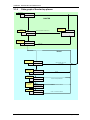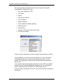
1
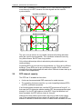
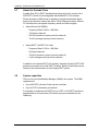
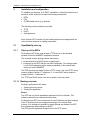
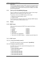
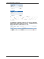
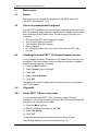
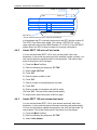
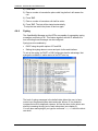
Installation, Administration and Maintenance of the SIP-DECT solution Aastra Telecom © June 2007 - All Rights Reserved No part of this document may be reproduced or transmitted in any form or by any means, electronic or mechanical, including photocopying, recording, or information storage and retrieval system, for any purpose without the express written permission of Aastra. Installation, Administration and Maintenance Table of contents 1 OVERVIEW ........................................................................................................................................................... 4 1.1 PURPOSE ........................................................................................................................................................ 4 1.2 ABBREVIATIONS AND DEFINITIONS ............................................................................................................... 4 1.2.1 Abbreviations ................................................................................................................................. 4 1.2.2 Definitions...................................................................................................................................... 4 1.3 REFERENCES.................................................................................................................................................. 6 2 INTRODUCTION.................................................................................................................................................. 8 2.1 ABOUT THE AASTRA SIP-DECT SOLUTION ................................................................................................. 8 2.2 ABOUT THE ACCESS POINTS (RFP’S) ........................................................................................................... 9 2.3 OPENMOBILITY MANAGER ......................................................................................................................... 11 2.4 IP SIGNALLING AND MEDIA STREAM ........................................................................................................... 11 2.5 RFP SYNCHRONIZATION ............................................................................................................................. 14 2.6 RFP CHANNEL CAPACITY ............................................................................................................................ 15 2.7 ABOUT THE PORTABLE PARTS .................................................................................................................... 16 2.8 SYSTEM CAPACITIES.................................................................................................................................... 16 3 INSTALLATION AND CONFIGURATION................................................................................................... 17 3.1 OPENMOBILITY START UP ........................................................................................................................... 17 3.1.1 Start up of the RFPs ..................................................................................................................... 17 3.1.1.1 3.1.2 3.1.3 3.1.3.1 3.1.3.1.1 3.1.3.1.2 3.1.3.1.3 3.1.3.2 3.1.4 DHCP client ............................................................................................................................... 18 DHCP request ............................................................................................................................ 18 DHCP offer ................................................................................................................................ 19 Retries ........................................................................................................................................ 19 TFTP client................................................................................................................................. 19 Application................................................................................................................................... 19 3.1.4.1 3.1.4.1.1 3.1.4.1.2 3.1.4.2 3.2 3.3 Booting overview....................................................................................................................... 17 Start up of the OpenMobility Manager ....................................................................................... 18 Booter ........................................................................................................................................... 18 Booter update ............................................................................................................................. 20 Automatic booter update ........................................................................................................... 20 Automatic booter update for major release changes................................................................. 21 Selecting the right DHCP server................................................................................................ 21 3.1.5 RFP LED status............................................................................................................................ 21 3.1.6 State graph of the start up phases ................................................................................................ 23 STATIC LOCAL CONFIGURATION OF AN RFP ............................................................................................... 24 CONFIGURING THE OPENMOBILITY MANAGER .......................................................................................... 26 3.3.1 Service Login procedure.............................................................................................................. 26 3.3.2 System .......................................................................................................................................... 27 3.3.2.1 3.3.2.1.1 3.3.2.1.2 3.3.2.1.3 3.3.2.2 3.3.2.3 3.3.2.4 3.3.2.5 3.3.3 RFP configuration ........................................................................................................................ 34 3.3.3.1 3.3.3.2 3.3.3.3 3.3.4 System settings........................................................................................................................... 28 Restarting the OMM.................................................................................................................. 29 Encryption.................................................................................................................................. 29 Regulatory domain .................................................................................................................... 30 SIP .............................................................................................................................................. 30 User account............................................................................................................................... 32 Time zones ................................................................................................................................. 32 Backup........................................................................................................................................ 34 DECT configuration................................................................................................................... 36 States of a RFP ........................................................................................................................... 36 OMM / RFP SW version check ................................................................................................. 36 Configuration of Portable Parts ................................................................................................... 38 4 MAINTENANCE................................................................................................................................................. 41 4.1 BOOTER ....................................................................................................................................................... 41 4.2 SITE SURVEY MEASUREMENT EQUIPMENT .................................................................................................. 41 4.3 CHECKING THE AASTRA DECT 142 HANDSET FIRMWARE VERSION ......................................................... 41 4.4 DIAGNOSTIC ................................................................................................................................................ 41 4.4.1 Aastra DECT 142 site survey mode ............................................................................................ 41 4.4.2 Aastra DECT 142 auto call test mode ......................................................................................... 42 4.4.3 Aastra DECT 142 auto answer test mode ................................................................................... 42 4.4.4 Syslog ........................................................................................................................................... 43 5 APPENDIX ........................................................................................................................................................... 44 Aastra Telecom Page: 2 (47) Installation, Administration and Maintenance 5.1 5.2 COMMUNICATIONS REGULATION INFORMATION FOR AASTRA PHONE 142 US ........................................ 44 COMMUNICATIONS REGULATION INFORMATION FOR RFP 32 OR RFP 34 (NA) ...................................... 45 Aastra Telecom Page: 3 (47) Installation, Administration and Maintenance 1 Overview 1.1 Purpose This document describes the installation, configuration and maintenance of the Aastra SIP-DECT solution. 1.2 Abbreviations and definitions 1.2.1 Abbreviations AC ADPCM DHCP DSP Authentication Code Adaptive Differential Pulse Code Modulation Digital Enhanced Cordless Telecommunication Dynamic Host Configuration Protocol Digital Signal Processor FCC GAP IPEI HTTP OMM PARK PP SNMP TFTP RFP RTCP RTP Federal Communications Commission Generic Access Profile International Portable Equipment Identity Hyper Text Transfer Protocol OpenMobility Manager Portable Access Rights Key Portable Part (DECT handset) Simple Network Management Protocol Trivial File Transfer Protocol Radio Fixed Part (Access Point) Real Time Control Protocol Real Time Protocol DECT 1.2.2 Definitions Aastra DECT 142 Aastra DECT 142 Handset Handset In the context of the Aastra SIP-DECT solution, an Aastra DECT 142 handset and Portable Part (PP) are interchangeable. Access Point Access Point In the context of the Aastra SIP-DECT solution, an Access Point and a Radio Fixed Part (RFP) are interchangeable. Asterisk Asterisk Asterisk is a complete Open Source PBX in software. It runs on Linux, BSD and MacOSX and provides many features. Asterisk supports voice over IP in many protocols, and can interoperate with almost all standardsbased telephony equipment. DECT Aastra Telecom Digital Enhanced Cordless Telecommunication Page: 4 (47) Installation, Administration and Maintenance • The standard (ETS 300 175) essentially specifies the air interface, known as the radio interface. Voice and data can both be transmitted via this interface. • Its technical key characteristics for Europe are: • • • • • Frequency range: approx. 1.880 – 1.900 GHz (approximately 20 MHz bandwidth) 10 carrier frequencies (1.728 MHz spacing) with 12 time slots each) Doubling the number of time slots (to 24) using the TDMA process Net data rate per channel of 32 kbps (for voice transmission using ADPCM) Voice coding using the ADPCM method Its technical key characteristics for North American are: • • • • • GAP Aastra Telecom Frequency range: approx. 1.920 – 1.930 GHz (approximately 10 MHz bandwidth) 5 carrier frequencies (1.728 MHz spacing) with 12 time slots each) Doubling the number of time slots (to 24) using the TDMA process Net data rate per channel of 32 kbps (for voice transmission using ADPCM) Voice coding using the ADPCM method Generic Access Profile • GAP is the abbreviation for Generic Access Profile • The GAP standard (ETS 300 444) is based on the same technology as DECT, but is limited to the most important basic features. This standard was created in order to allow telephones of different vendors to be used on any type of DECT system. It thus represents the smallest common denominator of all manufacturerspecific variants of the DECT standard. • An important limitation in the GAP standard is that external handover is not possible. For this reason connection handover is used, which is supported by GAP terminals. • The operation of GAP-capable telephones is comparable to that of analogue terminals. For example, features can be called up via ‘*’ and ‘#’ procedures. Page: 5 (47) Installation, Administration and Maintenance Handover Handover A handover is similar to roaming, but occurs during an ongoing call. A handover normally takes place “in the background”, without disrupting the call (seamless handover). IPEI International Portable Equipment Identity • 13-digit identification code for PPs • Example: 00019 0592015 3 (the final digit is the checksum). • The code is represented in decimal form. • This code is globally unique. PARK Portable Access Rights Key Access code for the Portable Part. This code determines whether a PP can access a particular DECT system. Used for unique selection of the system at handset enrolment/subscription time. Provided with the Aastra OMM Activation Kit and unique to each SIP-DECT deployment. Roaming Roaming While in motion, the PP performs ongoing measurements to determine which RFP is best received. The one that can be best received is defined as the active RFP. To prevent the PP from rapidly switching back and forth between two RFPs that have similar signal strength, certain threshold values are in effect. 1.3 References /1/ RFC 1350, The TFTP Protocol, Revision 2, July 1992 /2/ RFC 1889, RTP: A Transport Protocol for Real-Time Applications, January 1996 /3/ RFC 2030, Simple Network Time Protocol (SNTP) Version 4 for IPv4, IPv6 and OSI, October 1996 /4/ RFC 2131, Dynamic Host Configuration Protocol, March 1997 /5/ RFC 2327, SDP: Session Description Protocol, April 1998 /6/ RFC 2474, Definition of the Differentiated Service Field (DS Field) in the IPv4 and IPv6 Headers, December 1998 /7/ RFC 2617, HTTP Authentication: Basic and Digest Access Authentication, June 1999 /8/ RFC 3164, The BSD Sys Log Protocol, August 2001 Aastra Telecom Page: 6 (47) Installation, Administration and Maintenance /9/ RFC 2833, RTP Payload for DTMF Digits, Telephony Tones and Telephony Signals, May 2000 /10/ RFC 3261, Session Initiation Protocol (SIP), June 2002 /11/ RFC 3264, An Offer/Answer Model with Session Description Protocol (SDP), June 2002 /12/ RFC 3420, Internet Media Type message/sipfrag, November 2002 /13/ RFC 3515, The Session Initiation Protocol (SIP) Refer method, April 2003 /14/ RFC 3665, The Session Initiation Protocol (SIP) Basic Call Flow Examples, December 2003 /15/ RFC 3842, A Message Summary and Message Waiting Indication Event Package for the Session Initiation Protocol (SIP), August 2004 /16/ RFC 3891, The Session Initiation Protocol (SIP) “Replaces” Header, September 2004 /17/ RFC 3892, The Session Initiation Protocol (SIP) Referred-By Mechanism, September 2004 /18/ OpenMobility Diagnostic Tools Aastra Telecom Page: 7 (47) Installation, Administration and Maintenance 2 Introduction 2.1 About the Aastra SIP-DECT solution The Aastra SIP-DECT solution comprises the following components: • Aastra SIP-DECT Access Points (also known as Radio Fixed Parts (RFP’s)) being distributed over an IP network and offering DECT wireless and IP interfaces. • A SIP Call Manager/IP PBX/Media Server platform (e.g. Asterisk). • Aastra DECT Handsets (also known as Portable Parts (PP)) • OpenMobility Manager (OMM): Management interface for Aastra’s SIP DECT solution, which runs on one of the Radio Fixed Parts. The following pictures give a graphical overview of the architecture of the IP DECT wireless solution: Media Server Media Gateway Radio Fixed Parts 255 max. Web browser for administration purposes OMM The IP PBX/media server/media gateway, OMM and the RFPs communicate through the IP infrastructure. The RFPs and the Portable Parts communicate over the air. Aastra Telecom Page: 8 (47) Installation, Administration and Maintenance 2.2 About the Access Points (RFP’s) Aastra has two versions of Access Points, indoor and outdoor models RFP32 and RFP34 respectively. RFP references apply to both models. In general all RFPs have the same hardware and software capabilities. Please be aware of the regulatory differences between North America and all other areas of the world . These differences lead to different RFP variants which use specific frequency bands and field strengths: • • RFP 32 IP or RFP 34 IP (EMEA) - Frequency Band 1.880 to 1.900 Mhz - 10 carrier frequencies - Transmit Power 24 dBm RFP 32 NA or RFP 34 NA (NA) - Frequency Band 1.920 to 1.930 Mhz - 5 carrier frequencies - Transmit Power 20 dBm One RFP within a SIP-DECT installation must be declared to operate as the OpenMobility Manager (OMM). The RFP acting as the OMM may also act as a regular RFP as well if it is included into a DECT Cluster. Aastra Telecom Page: 9 (47) Installation, Administration and Maintenance RFP only mode Within this mode the RFP converts IP protocol to DECT protocol and then transmits the traffic to and from the handsets over a DECT time slot. On air the RFP has 12 available time slots, 8 can have associated DSP resources for media streams, the remaining 2 time slots are used for control signalling between RFPs and the PPs, and 2 time slots are reserved for hand-in purposes. Groups of RFPs can be built which are named clusters. Within a cluster RFPs are synchronized to enable a seamless handover when a user crosses from one RFP’s zone of coverage to another. For synchronization it is not necessary for an RFP to communicate directly with all other RFPs in the system. Each RFP only needs to be able to communicate with the next RFP in the chain. But it is preferable for a RFP to see more than one RFP to guarantee synchronization in the event that one of the RFPs fails. The 2 control signalling channels are also used to carry bearer signals that signal the handset to start the handover process. If the radio signal of another RFP is stronger than that of the current RFP, then the handset starts the handover process to the RFP that has the stronger signal as the user moves around the site. OpenMobility Manager mode In this mode a RFP functions as a regular RFP. Additionally it is responsible for SIP signalling between the IP DECT system and the telephony or media server. Further on it takes over the management part of the IP DECT solution. You designate a RFP as the OMM by assigning an IP address to the RFP within the DHCP scope (see 3). After a RFP is designated as the OMM, it starts the extra services on board (for example, the web service that supports the management interface). All RFP’s download the same firmware from a TFTP server but only one RFP activates the OMM services. Note: It is possible to deactivate the DECT part of a RFP. If the DECT interface is deactivated then the resources (CPU and memory) are available for the OMM. RFP32 Unused LED LED green (Application) LED orange (Application) LED red (Booter) Ethernet jack Power supply in line with Power over LAN™ standard IEEE 802.3af Power jack (120 V/230 V AC adapter) Aastra Telecom Page: 10 (47) Installation, Administration and Maintenance 2.3 OpenMobility Manager The OpenMobility Manager (OMM) performs the following tasks: • Signalling gateway (SIP <-> DECT). • Media stream management. • Managing sync-over-air functions between RFPs. • Facilitating system configuration modifications. The OpenMobility Manager (OMM) runs on one of the RFP’s. 2.4 IP signalling and media stream To establish a call between an IP Phone and a PP (Aastra DECT 142 Handset), the following IP streams must be established: • A signalling channel to and from the SIP phone. • A signalling channel to and from the OMM. • A control interface between the OMM and the RFP that has a connection to the PP (known as the primary RFP). • A Real Time Protocol (RTP) / Real Time Control Protocol (RTCP) connection between the SIP phone and the media gateway and then a RTP/RTCP connection between the media gateway and the RFP. The following figure illustrates this scenario. SIP-Phone Media Server Media Gateway Primary RFP OMM (RFP in OMM mode) Signalling RFP Control Interface RTP/RTCP To establish a call between two PPs the same IP streams must be established like in the scenario before, except the IP phone is not involved. The following figure illustrates this scenario. Aastra Telecom Page: 11 (47) Installation, Administration and Maintenance Media Server Media Gateway OMM (RFP in OMM mode) Signalling RFP Control Interface RTP/RTCP A call from one PP to another that resides on the same RFP will loop back within the RFP, if no media gateway is involved. So the call will not pass through to the Local Area Network (LAN). Although the voice packets will not impact LAN traffic, signal packets will. It is also be possible to direct the media stream to connect directly the IP phone and the RFP, as shown in the following figures. Aastra Telecom Page: 12 (47) Installation, Administration and Maintenance If the PP user is moving, the PP detects that another RFP has a better signal strength and, therefore, it starts the handover process. The media stream from the IP phone cannot move to the secondary RFP, so the primary RFP uses the LAN to direct the voice to the secondary RFP, as shown in the following figure. SIP-Phone Media Server Media Gateway Secondary RFP Primary RFP OMM (RFP in OMM mode) Signalling RFP Control Interface RTP/RTCP As the PP user moves into the next RFP zone of coverage, the PP detects that the RFP has a better signal strength. Again the media stream from the SIP phone cannot move to the secondary RFP, so the primary RFP uses the LAN to direct the voice to the new secondary RFP. Aastra Telecom Page: 13 (47) Installation, Administration and Maintenance SIP-Phone Media Server Media Gateway New secondary RFP Primary RFP OMM (RFP in OMM mode) Signalling RFP Control Interface RTP/RTCP 2.5 RFP Synchronization To guarantee a seamless handover if a caller moves from one RFP zone of coverage to another RFP zone of coverage, an accurate synchronization of the RFPs is necessary. The RFPs are synchronized over the air interface. The first RFP to complete start-up will transmit a signal on the air for the other RFPs to synchronize from. If a RFP gets in sync then it will transmit a signal on the air and will be the sync source for the next RFP. Only RFPs which can receive a synchronization signal will become synchronized. For the RFP to sync to another RFP the signal strength cannot drop below –70 dBm. You must consider this requirement during the site survey. The first active RFP will be chosen by the ADMM. Unsynchronized RFP, which R does 101 not receive a R 102 signal from another RFP R 103 R 104 R 108 R 107 R 105 Unsynchronized RFP, which receives a signal from another RFP and tries to get synchronized R 111RFP, R 110 R 109 Synchronized which receives and transmits a signal on the air interface R 106 As long as an RFP is not in sync, no calls can be established using this RFP. If a RFP loses the synchronization the RFP does not accept new calls (“busy bit”). There is a delay of maximum 3 minutes until the active calls on this RFP are finished. Then it tries to get synchronized again. Aastra Telecom Page: 14 (47) Installation, Administration and Maintenance An IP DECT installation is more reliable if a RFP can receive the signal from more than only one RFP, because the other signals are also used for synchronization. Unreliable Installation R 101 R 102 R 103 R 104 R 105 Don‘t R 111 R 110 R 109 R 108 R 107 R 106 Reliable Installation R 101 R 102 R 111 R 110 R 109 R 103 R 108 R 104 R 107 R 105 R 106 The sync-over-air solution is very reliable, because all existing redundant paths are used for synchronization. Thus, hardware tolerances have only very little influence. No RFP has a key position. Only unfavourable setups without redundant synchronization paths can cause problems. Sometimes RFPs do not need to be synchronized, e.g. if they are in different buildings. These RFPs can be put into different clusters. RFPs in different clusters will not be synchronized with each other. Different clusters start up at the same time independently. 2.6 RFP channel capacity The RFP has 12 available air time slots: • 8 slots can have associated DSP resources for media streams. • The remaining 4 slots are used for e.g. control signalling between RFPs and PPs, and hand-in purposes. If all 8 media stream channels are used the RFP announces a “busy bit”. In that case the PPs determine whether another RFP has an appropriate signal strength. If so, the PP will handover to that RFP. Once the handover has been completed, the RFP will then lower its “busy bit”. Whenever the busy state is announced a log entry is made to the system logs. If the announcement of busy raises in a specific area, a further RFP should be installed to double the number of media streams available for calls. Aastra Telecom Page: 15 (47) Installation, Administration and Maintenance 2.7 About the Portable Parts Portable Part (PP) is DECT standard terminology and in the context of the SIP-DECT solution is interchangeable with Aastra DECT 142 Handset. Please be aware of differences in regulatory requirements between North America and all other areas of the world. These differences lead to different PP variants which use specific frequency bands and field strengths: • • Aastra Phone 142 (EMEA) - Frequency Band 1.880 to 1.900 Mhz - 120 duplex channels - 250 mW (maximum output per active channel) - 10 mW (average output per active channel) Aastra DECT 142 DECT142 (NA) - Frequency Band 1.920 to 1.930 Mhz - 60 duplex channels - 100 mW (maximum output per active channel) - 5 mW (average output per active channel) In addition to the Aastra DECT 142 Handset, standard 3rd party DECT GAP phones may operate on the SIP-DECT solution. But the functionality may be limited by the characteristics of the 3rd party DECT phone. 2.8 System capacities There is only one OpenMobility Manager (OMM) in the system. The OMM capacities are: • Up to 256 RFPs (Access Points) can be controlled. • Up to 512 PPs (Handsets) are handled. It is possible to deactivate the DECT part of a RFP. If the DECT interface is deactivated then the resources (CPU and memory) are available for the OMM only. Aastra Telecom Page: 16 (47) Installation, Administration and Maintenance 3 Installation and configuration To establish and maintain an IP DECT installation, a network infrastructure is assumed, which comprises at least the following components: • • • RFPs PPs IP PBX/media server (e.g. Asterisk) The following services should be provided: • • • TFTP DHCP Syslog daemon Note: Outdoor RFP’s should only be installed with antenna shipped with the units. No other antennas or cabling is permitted. 3.1 OpenMobility start up 3.1.1 Start up of the RFPs For booting a RFP there must at least a TFTP server on the attached network to load the OMM/RFP application software. The essential network settings can be alternatively • Communicated by a DHCP server at startup time. • Configured on the RFP with the tool OM Configurator. The settings made by the OM Configurator will be saved permanently in the internal flash memory of each OMM/RFP. The RFP gets the boot image file from a TFTP server. The used TFTP server needs to support Section 1.3 reference /1/. A used DHCP server needs to support Section 1.3 reference /4/. The TFTP and DHCP server need not to reside on the same host. 3.1.1.1 Booting overview Booting is performed in two steps: 1. Starting the boot process. 2. Starting the application. Booter The RFP has only a little standalone application built into the flash. This software realizes the so called net boot process. On startup each RFP tries to determine its own IP address and other settings of the IP interface from the configuration settings in the internal flash memory. If no settings are available or these settings are disabled, the RFP tries to determine these settings via DHCP. The RFP gets the application image file from the TFTP server. Aastra Telecom Page: 17 (47) Installation, Administration and Maintenance Application After starting the application image the RFP checks the local network settings in its internal flash memory once again. If no settings are available or if they are disabled it starts a DHCP client to determine the IP address of the OMM and other startup settings. 3.1.2 Start up of the OpenMobility Manager There is no difference in booting that RFP, which is chosen to be running in OMM mode from those which are in the RFP only mode. The decision is driven by the OMM IP address, which is read • Within the local network settings, if active. • Via DHCP request. The RFP which has the same IP address as the dedicated OMM IP address, will be the RFP which the OMM software runs on. 3.1.3 Booter 3.1.3.1 DHCP client Within the initial boot process the DHCP client supports the following parameters: • • • • • • IP address Netmask Gateway Boot file name TFTP server Public option 224: “OpenMobility” mandatory mandatory mandatory mandatory mandatory mandatory • Public option 226: OMM IP Address mandatory (used with Option 43) 3.1.3.1.1 DHCP request 3.1.3.1.1.1 Vendor class identifier (code 60) The DHCP client sends the vendor class identifier “OpenMobility”. 3.1.3.1.1.2 Parameter request list (code 55) The DHCP client in the booter requests the following options in the parameter request list: • Subnet mask option (code 1) • Router option (code 3) • Public option 224 (code 224) • Public option 225 (code 225) • Public option 226 (code 226) Aastra Telecom Page: 18 (47) Installation, Administration and Maintenance 3.1.3.1.2 DHCP offer The DHCP client selects the DHCP server according to the following rules: • The public options (code 224) has a value equal to the string “OpenMobility”. or • the file field in the DHCP message has a sub string equal to “ip_rfp.cnt”. If none of the two rules above match the DHCP offer is ignored. Information retrieved from the DHCP offer: • The IP address to use is taken from the yiaddr field in the DHCP message. • The IP netmask is taken from the subnet mask option (code 1). • The default gateway is taken from the router option (code 3). • The TFTP server IP address is taken from the (code 66) field in the DHCP message. • The boot image filename is taken from the (code 67) field in the DHCP message, if this field is empty the default filename “iprfp.bin” is used. 3.1.3.1.3 Retries If the DHCP client does not get an appropriate DHCP offer a new DHCP request is send after 1 second. After 3 DHCP requests are sent the DHCP client will sleep for 60 seconds. During this time the booter will accept a local configuration with the OpenMobility Configurator (OMC). This cycle will repeat every 3 minutes until either ALL the required DHCP options are provided or the system is manually configured using the OM Configurator tool. 3.1.3.2 TFTP client The TFTP client will download the application image from the TFTP server. Both TFTP server and the name of the application image are supplied via the DHCP client. The application image is checksum protected. 3.1.4 Application After successfully downloading and starting the application the RFP will determine the IP address of the OMM from DHCP. The DHCP client is capable of receiving broadcast and unicast DHCP replies. Therefore the flags field is 0x0000. The DHCP request contains the well-known magic cookie (0x63825363) and the end option (0xFF). The following parameters will be supported within this step: Option / Field Aastra Telecom Meaning Mandatory Page: 19 (47) Installation, Administration and Maintenance yiaddr IP-Address of the IP-RFP yes Code 66 Parameter named Boot Server Host Name with value as the IP-Address of the TFTP server yes Code 67 Parameter named Bootfile Name with value of the path (optional) and name of the application image. For example omm_ffsip.tftp. yes code 1 Subnet mask yes code 3 Default Gateway yes code 6 Domain Name Server No code 15 Domain Name No code 42 IP-Address of a NTP server No code 43 Vendor Specific Options yes public option 224 Parameter named magic_str must set to value "OpenMobility". yes The Vendor Specific Options consist of: Vendor Specific Option option 226 option 7 option 15 option 17 option 18 Meaning Mandatory ommip: Used to select the IP-RFP who should reside the Open Mobility Manager (OMM) yes syslogip: IP-Address of a Syslog Daemon syslogport: Port of a Syslog Daemon Country: Used to select the country in which the OMM resides. This enables country specific tones (busy tone, dial tone, ...) ntpservname: Name of a NTP Server No No No No An example of the minimal contents for the Option 43 parameter value would be: 11 02 00 01 0a 04 C0 A8 00 01 where C0 A8 00 01 represents 192.168.0.1 for the OMM IP Tones for the following countries are supported: country code 1 2 3 4 6 7 8 9 10 14 16 25 100 101 country Germany Great Britain Suisse Spain Italy Russia Belgium Netherlands Czechia Finland Poland Taiwan North America France 3.1.4.1 Booter update 3.1.4.1.1 Automatic booter update Aastra Telecom Page: 20 (47) Installation, Administration and Maintenance Each application SW comes with the latest released booter SW. The application SW will update the booter automatically as long as the major release number of the booter SW has not changed, e.g booter SW 2.1.2 will not be automatically updated by the booter SW 3.x.y, but the booter SW 3.0.0 will be automatically updated by the booter SW 3.1.0. 3.1.4.1.2 Automatic booter update for major release changes The update of booters with a major release number change will be performed automatically when the DHCP client in the application receives an DHCP offer with the public option 254 with a value “UPDATE”. 3.1.4.2 Selecting the right DHCP server The DHCP client requests its own IP address using code 50. The DHCP client will select the DHCP server that offers the currently used IP address. Additionally the mandatory options must be offered otherwise the DHCP offer is ignored by the DHCP client. If no matching reply was received the DHCP client resends the request for 2 times after 1 second. Then the DHCP client will wait for 1 minute before resending 3 requests again. If the DHCP client cannot accept an DHCP offer within 3 minutes the RFP is rebooted. 3.1.5 RFP LED status The following diagram shows the LED status of a RFP according to the different states during start up. The RFP32 IP has three separate LEDs for red, orange and green to show the different states during start up. RFP32 Unused LED LED green (Application) LED orange (Application) LED red (Booter) Ethernet jack Power supply in line with Power over LAN™ standard IEEE 802.3af Power jack (120 V/230 V AC adapter) State LED state Remarks Booter (Start up) Red on Waiting for link up Booter DHCP Red flashing 0.5 Hz Launching a DHCP request and waiting for an DHCP offer Aastra Telecom Page: 21 (47) Installation, Administration and Maintenance State LED state Remarks Booter (TFTP) Red flashing 2.5 Hz Downloading the application image Application (DHCP) Orange on Launching DHCP request and waiting for DHCP reply Application (init) Green flashing 0.5 Hz RFP is initializing its internal components Application (init) Green flashing 1 Hz RFP tries to connect to the OMM Application (init) Green flashing (2 sec on, 0.5 sec off) The DECT part of the RFP does not work (either not configured or not synchronized with other RFP’s) Application (init) Green RFP is up and running Aastra Telecom Page: 22 (47) Installation, Administration and Maintenance 3.1.6 State graph of the start up phases LED RED ON Start-up wait for link up BOOTER LED red flashing 0,5 Hz LED red flashing 0,25 Hz retry DHCP no answer / offer not o.k. DHCP Wait for 60 seconds wait for reply LED red flashing 2,5 Hz TFTP File download TFTP failed Kernel LED orange DHCP wait for reply LED green flashing (0,5 Hz) Application Init LED green flashing 1 Hz Init failed Application Connect to OMM LED green flashing 2 seconds on / 50ms off DHCP no answer; offer not o.k. (try 3 minutes) Application Connection attempt to OMM failed Failure, i.e. connection to OMM lost Synchronize DECT LED green Application Failure, i.e. connection to OMM lost Up & running Aastra Telecom Page: 23 (47) Installation, Administration and Maintenance 3.2 Static local configuration of an RFP As an alternative to DHCP configuration, the RFPs/OMM may be individually statically configured using the OM Configurator tool. For a static local configuration you must use the java configuration tool OpenMobility Configurator which requires Java Runtime Environment version 1.4 or higher. The settings, which are configured on the RFP with the tool OM Configurator, will be saved permanently in the internal flash memory of an RFP. The parameters configurable via the OM Configurator comply with the DHCP option, please see section 3.1 for details. If a local static configuration has been done, DHCP is not used anymore. The following figure shows the OM Configurator. Note, version number will change with each OMM release. To configure an RFP, at least the MAC address and all mandatory options (see table below) have to be set. The MAC address must be entered in a format such as xx-xx-xx-xx-xx-xx. If the RFP has an IP address enter this address in the IP address field. In this case you can reach the RFP from outside the local LAN segment. Optional. To set additional parameters, press the “Add parameter” button and choose the desired parameter. IMPORTANT: Select the “yes” checkbox for the RFP to “Use local configuration” otherwise DHCP will be used. Aastra Telecom Page: 24 (47) Installation, Administration and Maintenance The recommended parameters that should be configured through the OpenMobility Configurator Tool are: • Use local configuration: YES • IP Address • Subnet • TFTP Server Address • TFTP File Name • OMM IP Address • Router Addresses (default gateway) • DNS Addresses • DNS Domain • Country (ie 100 for North American tones) • NTP Server Address Press the “Send configuration” button to transmit the parameters to an RFP. The configuration can only be set after powering up or at the retry phase (LED flashing 0,25 Hz) or in kernel mode, please see section 3.1.6 for details. The configurator tool waits 2 seconds and retries transmitting the data 3 times. If you want to read the configuration parameters from an RFP set the MAC address and the IP address additionally and press the “List configuration” button. All parameters will be listed in the OM Configurator tool. Press the “Reset configuration" button to clean all input fields and additional parameters. Aastra Telecom Page: 25 (47) Installation, Administration and Maintenance 3.3 Configuring the OpenMobility Manager The OMM runs on a designated RFP within a SIP-DECT deployment. The OMM is designated via DHCP options or statically declared via the OM Configurator tool. All other RFPs in the deployment are configured to point back to the OMM in the deployment. The OMM can be configured via HTTP. The OMM acts as a HTTP server which binds to port 80 by default. If executed in host mode the port can be configured via the command line interface. The configuration data will be either read from the internal flash memory or from a local file. A local file is only used if specified on the command line on a PC host. The configuration file is a human readable ASCII file. Changing the configuration file outside the OMM is not permitted. The configuration file can be downloaded and uploaded via the web interface. The service access is restricted to one active session at a time and is password protected. The browser used for service access has to be at least Microsoft Internet Explorer 6.0 or Mozilla Firefox 1.0 and must have frame support, JavaScript and cookies enabled. 3.3.1 Service Login procedure The OMM allows only one user at a time to configure the system. A user must authenticate with a user name and a password. Both strings are checked case sensitive. Default login is “omm” and password is “omm”. Administrators should change the admin password on the System page after accessing the OMM. Aastra Telecom Page: 26 (47) Installation, Administration and Maintenance After login there are the following options available: Configuration of general SIP-DECT system parameters. Administration of the attached RFPs. Administration of the PPs. If no user action takes place the OMM logs out the user after 5 minutes. To logout from the system click the “Logout” button. Note: If the browser is closed without logging out first the service access will be blocked for other clients for 5 minutes. 3.3.2 System Aastra Telecom Page: 27 (47) Installation, Administration and Maintenance 3.3.2.1 System settings The system settings cover global settings for the OpenMobility Manager like: • System Name • DECT Authentication Code. The authentication code is used during initial PP subscription as a security option (see chapter 3.3.4). It is optional. • PARK Each DECT network requires a unique PARK key. Enter the PARK key as provided with the OMM Activation Kit product. It is mandatory. • Encryption as described in the chapter 3.3.2.1.2 • Regulatory Domain as described in the chapter 3.3.2.1.3 • DECT Monitor For monitoring the DECT system behaviour of the OpenMobility Manager a separate application will be delivered. This tool needs an access to the OpenMobility Manager which is disabled by default and can be enabled on the system page. • ToS and TTL Parameters To allow the prioritisation of Voice Packets and/or Signalling Packets (SIP) inside the used network the IP parameter ToS (Type of Service) should be configured here. • Syslog Parameters The OpenMobility Manager and the RFPs are capable of propagating syslog messages. This feature together with the IP address of a host collecting these messages can be configured. • Date and Time Parameters If SNTP is not used, date and time can be configured at the OMM. This has to be done to provide date and time to the Aastra Phone 142. The time zone, which is shown on this web page, has been configured at the IP region section of the web service. Please note, that in the case that SNTP is not used, the date and time has to be configured after every restart of the RFP, where the OpenMobility Manager is running. The date and time will be provided by the OpenMobility Manager to the Aastra Phone 142 if the Aastra Phone 142 initiates a DECT location registration. This will be done in the following cases: Aastra Telecom • Subscribing at the OMM • Entering the network again after the DECT signal was lost • Power on • Silent charging feature is active at the phone and the phone is taken out of the charger Page: 28 (47) Installation, Administration and Maintenance • After a specific time to update date and time 3.3.2.1.1 Restarting the OMM To restart the OMM select “System Settings” from the navigation tree and then select ‘Restart’. There is also the option to reset the configuration data. A reset web page is loaded then displaying a progress bar and the login web page is loaded automatically if the OMM is reachable again. 3.3.2.1.2 Encryption Encryption is only available on RFP32/34 products. Therefore it can only be enabled on the “System Settings” web page if there are no other Aastra RFP variants connected to the OMM. Aastra Telecom Page: 29 (47) Installation, Administration and Maintenance If encryption is enabled and another RFP variant connects to the OMM, its DECT air interface will not be activated. Note: The PPs have to support DECT encryption which is not a mandatory feature. 3.3.2.1.3 Regulatory domain To define where the IP DECT is used the parameter regulatory domain has to be configured. Existing installations are updated to the default value “EMEA (ETSI)”. To setup a North American FCC compliant installation the value has to be set to “US (FCC/CI)” In a North American US (FCC/CI) deployment, ETSI compliant RFPs are made inactive and can not be activated if the regulatory domain is set to “US (FCC/CI)”. Vice-versa is also true. Only US (FCC/CI) DECT 142 handsets may be connected to RFPs/OMM designed for the US market and configured to use the US (FCC/CI) regulatory domain. 3.3.2.2 SIP The SIP settings cover all global settings matching the SIP signalling and the RTP voice streams. Aastra Telecom • Proxy Server IP address or name of the SIP proxy server. If a hostname and domain are used for the proxy server parameter, ensure that a DNS server and domain are specified for your SIP-DECT system via DHCP or the OMM Configurator tool. • Proxy Port SIP proxy server’s port number. Default is 5060. To enable DNS SRV support for proxy lookups, use a value of 0 for the proxy port. • Registrar Server IP address or name of the SIP registrar. Enables the PPs to be registered with a Registrar. If a hostname and domain are used for the proxy server parameter, ensure that a DNS server and domain are specified for your SIP-DECT system via DHCP or the OMM Configurator tool. • Registrar Port SIP Registrar’s port number. Default is 5060. To enable DNS SRV support for registrar lookups, use a value of 0 for the registrar port. • Registration Period The requested registration period, in seconds from the registrar. Default is 3600. • Outbound Proxy Address of the outbound proxy server. All SIP messages originating from the OMM are sent to this server. For example, if Page: 30 (47) Installation, Administration and Maintenance you have a Session Border Controller in your network, then you would normally set its address here. Optional. Aastra Telecom • Outbound Proxy Port The proxy port on the proxy server to which the OMM sends all SIP messages. Optional. • Explicit MWI Subscription Some Media Server such as the Asterisk support Message Waiting Indication (MWI) based on /15/. A MWI icon will be presented on an Aastra DECT 142 if the user has received a voice message on his voice box which is supported by the Media Server. If Explicit MWI Subscription is enabled the OMM sends explicit for each PP a MWI Subscription message to the Proxy or Outbound Proxy Server. • RTP Port Base Each RFP needs a continuous port area of 68 UDP ports for RTP voice streaming. The RTP Port Base is the start port number of that area. Default is 16320. • Preferred Codec 1 – 5 Specifies a customized codec preference list which allows you to use the preferred Codecs. The Codec 1 has the highest and Codec 5 the lowest priority. • Silence Suppression Used to configure whether Silence Suppression is preferred or not. • DTMF Out-of-Band The OMM supports DTMF based on Section 1.3 reference /9/. • DTMF Payload Type If Out-of-Band is enabled the Payload Type specify the payload type which is used for sending DTMF events based on Section 1.3 reference /9/. Page: 31 (47) Installation, Administration and Maintenance 3.3.2.3 User account After initial installation or after removing the configuration file the OpenMobility service is accessible via a build-in user account with user “omm” and password “omm”. These settings which are case sensitive can be changed on the “User Account” web page. 3.3.2.4 Time zones A time and date resynchronization of the Aastra Phone 142 devices is described in chapter 3.3.2.1. In the time zone section the OpenMobility Manager provides all available time zones. They are set with their known daylight savings time rules adjusted to the Universal Coordinated Time (UTC) per default. The difference to the UTC time is shown in the “UTC Difference” column. In case of a configured daylight savings time rule this is also marked for each time zone. There is a possibility to change the time zone rules for maximal five time zones. Changed rules are marked with a bold time zone name in the table. The changes are saved in the configuration file and are restored after each Aastra Telecom Page: 32 (47) Installation, Administration and Maintenance OpenMobility Manager startup. The “Default” button sets all time zones back to the default values and deletes the changed time zone rules in the configuration file. With the “Configure Time Zone” dialog the standard time and the daylight savings time (DST) of a time zone can be changed. If the time zone has no DST only the UTC difference can be configured. For the DST both points of time (begin of standard time and begin of daylight savings time) have to be specified exactly. Therefore a certain day in the month or a certain week day in a month can be used. See the following screen shots as an example: Aastra Telecom Page: 33 (47) Installation, Administration and Maintenance 3.3.2.5 Backup The web service interface allows to save a copy of the current configuration on the local host (host where the browser application is executed) as well as to restore an older configuration. Restoring a previously saved configuration will lead to a reset of the OMM to take effect. 3.3.3 RFP configuration All configured RFPs are listed in tables grouped to clusters by its topographic relations. The RFPs are sorted by their Ethernet addresses. To ensure correct handover of a PP during a call, all involved RFPs must deliver the same clock signal to the PP. This is achieved by having the RFPs synchronized. There are conditions where synchronization is not possible, for instance with RFPs at remote locations. In this case the RFPs shall be grouped in different clusters. The OpenMobility Manager will not try to synchronize RFPs over cluster borders. All used clusters are displayed in the navigation bar on the left side and the OMM RFP is marked with a bold font. Aastra Telecom Page: 34 (47) Installation, Administration and Maintenance When the RFPs are connecting the OMM they submit their HW type. This type is displayed on the RFP list web page. New RFPs can be added to the system by pressing the “New” button. A popup window appears providing the configuration of a new RFP. Each RFP is identified by its MAC address (6 bytes hex format, colon separated). The Ethernet address is unique and can be found on the back of the chassis. For easier administration each RFP can be associated with a location string. The location string can hold up to 20 characters. The same popup window could be opened for an existing RFP by pressing the tool icon of the appropriate RFP. An RFP could be deleted by pressing the trash can icon . A similar popup window asks for confirmation showing the current configuration of this RFP. Aastra Telecom Page: 35 (47) Installation, Administration and Maintenance 3.3.3.1 DECT configuration The DECT functionality for each RFP can be switched on/off. If DECT is active the RFP can be added to a cluster. 3.3.3.2 States of a RFP For each RFP the state of the DECT subsystem is displayed. The states are: Synchronous The RFP is up and running. The RFP recognizes and is recognized by other RFPs in its cluster through its air interface and delivers a synchronous clock signal to the PPs. Asynchronous but active The RFP has not been able to synchronize to its neighbours yet. No DECT communication is possible. But nevertheless the RFP has already been able to connect to the OMM. This phase should usually last only for a few seconds after starting up the RFP or the OMM. If this state lasts longer this is an indication for a hardware or network failure. Searching The RFP has lost synchronization to its neighbours. No DECT communication is possible. This phase should usually last only for a few seconds after starting up the RFP or the OMM. If this state lasts longer or is re-entered after being in a synchronous state this is an indication for a bad location of the RFP. Inactive The RFP has connected to the OMM but the air interface has not been switched on yet. For any RFP with activated DECT functionality this phase should last only for a few seconds after starting up the RFP. If this state lasts longer this may indicate a hardware failure. Not connected The RFP was configured but has not connected to the OMM yet. Therefore the IP address column is empty. 3.3.3.3 OMM / RFP SW version check When the RFPs are connecting the OMM they submit their SW version. If this version differs from the OMM SW version the RFP connection attempt is rejected. This could happen when using several DHCP servers with different OpenMobility SW versions. In this case the RFP is marked with an error Aastra Telecom Page: 36 (47) Installation, Administration and Maintenance message. Moreover a global error message is displayed on the RFP list web page if at least one version mismatch has been found. Aastra Telecom Page: 37 (47) Installation, Administration and Maintenance 3.3.4 Configuration of Portable Parts At the Portable Parts web page all configured DECT handsets are sorted by their number. To keep the list concise, the complete list is split up into sub lists containing up to 100 handsets. The user can move back and forth in steps of 100 handsets. Because the browser function can not be used to search for a certain handset in all sub lists, a search function is available, which allows to find a handset by a given number or IPEI. Adding Portable Parts to the SIP-DECT system A new PP can be added to the system by pressing the “New” button. The following popup window appears allowing the configuration of a new PP. The Name parameter represents the SIP Display Name field. This parameter is optional but recommended. The Number is the SIP account number or extension for the PP. The IPEI is the DECT 142 handset IPEI number which can be found in the System Options menu of the DECT 142 handset. The DECT authentication code is used during initial DECT subscription as a security option and can be set here for each PP separately. If it is not configured the global authentication code on the “System Settings” web page, it is used (see chapter 3.3.2.1). This parameter is optional. Note: The authentication code can only be changed if the PP is not subscribed. The PP name can be changed, but this will not take effect until the PP is subscribed again. The SIP Authentication User Name is optional but recommended. It represents the name which will be used during SIP registration and authentication. If no name is given the number will be used by default. The password will be used during SIP registration and authentication. Aastra Telecom Page: 38 (47) Installation, Administration and Maintenance Subscribing Portable Parts to the SIP-DECT system After adding a PP configuration to the OMM the PP must be subscribed. The OMM must first be enabled to allow subscriptions to be take place from PP handsets. This is done by pressing the “Subscribe” button on the Portable Parts OMM webpage. The OMM will allow a subscription of configured but not subscribed PPs during the next hour only. The administrator must press the Subscribe button again to permit more PP handsets to subscribe to the SIP-DECT system. After the PP configuration is complete on the OMM and the OMM is allowing new subscriptions, each PP must subscribe to the system. On each PP handset, the administrator or user must subscribe to the SIPDECT system through the System/Subscriptions menu. The specific PARK code for the SIP-DECT system must be entered in order to subscribe to the system. IMPORTANT: the PARK code in numeric format can be found at the top-right corner of the Portable Parts OMM web page. Each SIP-DECT deployment will have a unique PARK code that was provided with the OMM Activation kit. If the administrator configured a global or individual Portable Part DECT authentication code, the administrator/user must enter in the code before the PP will subscribe to the system. If administrators/users have any difficulties subscribing to the SIP-DECT system, it is recommended that they power-off the PP handset and reattempt subscription again. This completes the subscription process for a PP on the SIP-DECT system. Editing Portable Parts in the SIP-DECT system A popup window appears when configuring an existing PP by pressing the tool icon . The only difference between the popup window for adding and editing PP units is the delete subscription checkbox. If this option is selected, the PP will be unsubscribed. Deleting Portable Parts in the SIP-DECT system Deleting of a PP can be done by pressing the trash can icon . A popup window appears and asks for confirmation. Searching for Portable Parts in the SIP-DECT system If the user wants to find a certain handset then the search function can be used. A click on the “Search” button provides the following pop-up window. Aastra Telecom Page: 39 (47) Installation, Administration and Maintenance The user can enter the handsets’ number or IPEI. At least one parameter has to be set. The entered number or IPEI has to match exactly with a handset’s number or IPEI. If number and IPEI are given then a handset has to exist in the OMM’s database whose number and IPEI match both otherwise the search fails. If a handset with the specified number and/or IPEI was found then a list is displayed which has this handset as the first entry. The search function can also be used to get to the right sub list in one step. Aastra Telecom Page: 40 (47) Installation, Administration and Maintenance 4 Maintenance 4.1 Booter The booter may be automatically upgraded via the DHCP option 254 “UPDATE” (see chapter 3.1.4.1). 4.2 Site survey measurement equipment If an SIP-DECT installation has to be planned, a sufficient distribution of the RFPs is necessary, which fulfills the requirements for reliable synchronization and connectivity to the Portable Parts. The site survey kit may help you. It comprises: • • • • • 4.3 One measuring RFP with its own power supply. A tripod and a battery for the RFP. Two reference PPs with chargers. Battery chargers. A measuring handset, which can monitor other makers DECT radio sources. Checking the Aastra DECT 142 Handset firmware version You can display the version information of the Aastra Phone 142 with a few keystrokes. Check the firmware version to determine whether an update is required to overcome any user issues. 1. Press the “Menu” soft key 2. Select “System” (only to highlight) 3. Press “OK”. 4. Select “Version Number” 5. Press “OK”. The display will show the software and the hardware version of the Aastra DECT 142 handset. 4.4 Diagnostic 4.4.1 Aastra DECT 142 site survey mode You can set the Aastra DECT 142 in “site survey mode” with a few keystrokes. In this mode the phone will display the RFPs and the actual field strength of the receiving signal in dBM. 1) Press the “Menu” soft key 2) Enter the following key sequence “R***76#” 3) Select “Site Survey” 4) Press “OK”. To leave the site survey mode switch the phone off and on again. The following display is shown on the Aastra Phone 142: Aastra Telecom Page: 41 (47) Installation, Administration and Maintenance PARK: 1F-10-FF-F0-21 RFPI RFP ID: 02* 10FFF21 02 Frame error FE PP: FP: Field strength -dBm 50 57 RFP ID RPN 02 01 00 Menu 50 Phonebook RFP ID: 02* *The ID of RFP to which the PP is currently associated to. In this example the PP is currently connected to the RFP with the number 02. The RFP 01 and 00 are also visible. The number “10FFF221 02” on the upper right side refers to the PARK (Example 1F-10-F2-21) of the SIP-DECT system and to the RFP to which the phone is currently connected to. 4.4.2 Aastra DECT 142 auto call test mode You can set the Aastra DECT 142 to “auto call test mode” with a few keystrokes. In this mode the phone will call a specified number cyclically. You can use this feature to generate traffic for test purposes. This mode is also active if the phone is on the charger. 1) Press the “Menu” soft key 2) Enter the following key sequence “R***76#” 3) Select “Auto Call Test” 4) Press “OK”. 5) Enter the phone number to call. 6) Press “OK”. 7) Enter a number of seconds between two calls. 8) Press “OK”. 9) Enter a number of seconds a call shall be active. 10) Press “OK”. The test will be started automatically. To stop the test, switch the phone off and on again. 4.4.3 Aastra DECT 142 auto answer test mode You can set the Aastra DECT 142 to “auto answer test mode” with a few keystrokes. In this mode the phone will answer incoming calls automatically. You can use this feature together this phones in the “auto call test mode” for test purposes. This mode is also active if the phone is on the charger. 1) Press the “Menu” soft key 2) Enter the following key sequence “R***76#” 3) Select “Auto Answer” Aastra Telecom Page: 42 (47) Installation, Administration and Maintenance 4) Press “OK”. 5) Enter a number of seconds the phone shall ring before it will answer the call. 6) Press “OK”. 7) Enter a number of seconds a call shall be active. 8) Press “OK”. The test will be started automatically. To stop the test switch the phone off and on again. 4.4.4 Syslog The OpenMobility Manager and the RFPs are capable of propagating syslog messages conforming to /8/. This feature together with the IP address of a host collecting these messages can be configured. Syslog has to be enabled by • DHCP using the public options 227 and 228. • Setting the syslog daemon server and port via the web interface. To set up the syslog via DHCP or OM Configurator has the advantage, that syslogs are available in earlier states of the RFP start up. The level of syslog messages in the default state allows the user, to have control over the general system state and major failures. If it is wished to increase the level for diagnostic reasons, this can be done via the telnet user shell by increasing the spy level of each subsystem (see chapter 0). You can also read syslogs if you type the command logread within the telnet user shell. Aastra Telecom Page: 43 (47) Installation, Administration and Maintenance 5 Appendix 5.1 Communications Regulation Information for Aastra Phone 142 US FCC Notices (U.S. Only) This device complies with part 15 of the FCC Rules. Operation is subject to the following two conditions: (1) This device may not cause harmful interference, and (2) this device must accept any interference received, including interference that may cause undesired operation. Modifications not expressly approved by this company could void the user's authority to operate the equipment. NOTE: This equipment has been tested and found to comply with the limits for a Class B digital device, pursuant to Part 15 of the FCC Rules. These limits are designed to provide reasonable protection against harmful interference in a residential installation. This equipment generates, uses and can radiate radio frequency energy and, if not installed and used in accordance with the instructions, may cause harmful interference to radio communications. However, there is no guarantee that interference will not occur in a particular installation. If this equipment does cause harmful interference to radio or television reception, which can be determined by turning the equipment off and on, the user is encouraged to try to correct the interference by one or more of the following measures: . Reorient or relocate the receiving antenna. . Increase the separation between the equipment and receiver. . Connect the equipment into an outlet on a circuit different from that to which the receiver is connected. . Consult the dealer or an experienced radio/TV technician for help. Health and Safety Information Exposure to Radio Frequency (RF) Signals: The wireless phone is a radio transmitter and receiver. It is designed and manufactured not to exceed the emission limits for exposure to radio frequency (RF) energy set by the Federal Communications Commission (FCC) of the U.S. Government. These limits are part of comprehensive guidelines and establish permitted levels of RF energy for the general population. The guidelines are based on the safety standards previously set by both U.S. and international standards bodies. These standards include a substantial safety margin designed to assure the safety of all persons, regardless of age and health. This device and its antenna must not be co-located or operating in conjunction with any other antenna or transmitter. Aastra Telecom Page: 44 (47) Installation, Administration and Maintenance This EUT has been shown to be capable of compliance for localized specific absorption rate (SAR) for uncontrolled environment/general population exposure limits specified in ANSI/IEEE Std. C95.1-1992 and had been tested in accordance with the measurement procedures specified in FCC/OET Bulletin 65 Supplement C (2001) and IEEE 1528-2003. Industry Canada (Canada only) Operation of this device is subject to the following two conditions: (1) this device may not cause interference, and (2) this device must accept any interference, including interference that may cause undesired operation of the device. Privacy of communications may not be ensured when using this telephone. Exposure to Radio Frequency (RF) Signals: The wireless phone is a radio transmitter and receiver. It is designed and manufactured not to exceed the emission limit for exposure to radio frequency (RF) energy set by the Ministry of Health (Canada), Safety Code 6. These limits are part of comprehensive guidelines and established permitted levels of RF energy for the general population. These guidelines are based on the safety standards previously set by international standard bodies. These standards include a substantial safety margin designed to assure the safety of all persons, regardless of age and health. This device and its antenna must not be co-located or operating in conjunction with any other antenna or transmitter. This device has been shown to be capable of compliance for localized specific absorption rate (SAR) for uncontrolled environment / general public exposure limits specific in ANSI/IEEE C95.1-1992 and had been tested in accordance with the measurement procedures specified in IEEE 1528-2003. 5.2 Communications Regulation Information for RFP 32 or RFP 34 (NA) FCC Notices (U.S. Only) This device complies with part 15 of the FCC Rules. Operation is subject to the following two conditions: (1) This device may not cause harmful interference, and (2) this device must accept any interference received, including interference that may cause undesired operation. Modifications not expressly approved by this company could void the user's authority to operate the equipment. Aastra Telecom Page: 45 (47) Installation, Administration and Maintenance NOTE: This equipment has been tested and found to comply with the limits for a Class B digital device, pursuant to Part 15 of the FCC Rules. These limits are designed to provide reasonable protection against harmful interference in a residential installation. This equipment generates, uses and can radiate radio frequency energy and, if not installed and used in accordance with the instructions, may cause harmful interference to radio communications. However, there is no guarantee that interference will not occur in a particular installation. If this equipment does cause harmful interference to radio or television reception, which can be determined by turning the equipment off and on, the user is encouraged to try to correct the interference by one or more of the following measures: . Reorient or relocate the receiving antenna. . Increase the separation between the equipment and receiver. . Connect the equipment into an outlet on a circuit different from that to which the receiver is connected. . Consult the dealer or an experienced radio/TV technician for help. Exposure to Radio Frequency (RF) Signals: The wireless phone is a radio transmitter and receiver. It is designed and manufactured not to exceed the emission limits for exposure to radio frequency (RF) energy set by the Federal Communications Commission (FCC) of the U.S. Government. These limits are part of comprehensive guidelines and establish permitted levels of RF energy for the general population. The guidelines are based on the safety standards previously set by both U.S. and international standards bodies. These standards include a substantial safety margin designed to assure the safety of all persons, regardless of age and health. This device and its antenna must not be co-located or operating in conjunction with any other antenna or transmitter. The radiating element of the RFP should be installed during operating at a separation distance greater than 20 cm between user and device. The device comply with the requirements for routine evaluation limits ” Industry Canada (Canada only) Operation of this device is subject to the following two conditions: (1) this device may not cause interference, and (2) this device must accept any interference, including interference that may cause undesired operation of the device. Privacy of communications may not be ensured when using this telephone. Exposure to Radio Frequency (RF) Signals: The wireless phone is a radio transmitter and receiver. It is designed and manufactured not to exceed the emission limit for exposure to radio Aastra Telecom Page: 46 (47) Installation, Administration and Maintenance frequency (RF) energy set by the Ministry of Health (Canada), Safety Code 6. These limits are part of comprehensive guidelines and established permitted levels of RF energy for the general population. These guidelines are based on the safety standards previously set by international standard bodies. These standards include a substantial safety margin designed to assure the safety of all persons, regardless of age and health. This device and its antenna must not be co-located or operating in conjunction with any other antenna or transmitter. The radiating element of the RFP should be installed during operating at a separation distance greater than 20 cm between user and device. This device comply with the requirements for routine evaluation limits. Aastra Telecom Page: 47 (47)