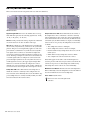
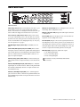
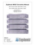
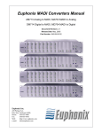
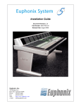
1
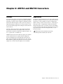
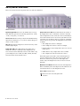
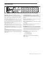
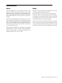
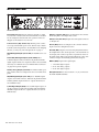
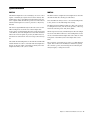
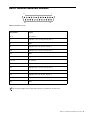
MADI 700 Series Guide System 5 Legal Notices This guide is copyrighted ©2011 by Avid Technology, Inc., (hereafter “Avid”), with all rights reserved. Under copyright laws, this guide may not be duplicated in whole or in part without the written consent of Avid. 003, 96 I/O, 96i I/O, 192 Digital I/O, 192 I/O, 888|24 I/O, 882|20 I/O, 1622 I/O, 24-Bit ADAT Bridge I/O, AudioSuite, Avid, Avid DNA, Avid Mojo, Avid Unity, Avid Unity ISIS, Avid Xpress, AVoption, Axiom, Beat Detective, Bomb Factory, Bruno, C|24, Command|8, Control|24, D-Command, D-Control, D-Fi, D-fx, D-Show, D-Verb, DAE, Digi 002, DigiBase, DigiDelivery, Digidesign, Digidesign Audio Engine, Digidesign Intelligent Noise Reduction, Digidesign TDM Bus, DigiDrive, DigiRack, DigiTest, DigiTranslator, DINR, DV Toolkit, EditPack, Eleven, HD Core, HD I/O, HD MADI, HD OMNI, HD Process, Hybrid, Impact, Interplay, LoFi, M-Audio, MachineControl, Maxim, Mbox, MediaComposer, MIDI I/O, MIX, MultiShell, Nitris, OMF, OMF Interchange, PRE, ProControl, Pro Tools, Pro Tools|HD, QuickPunch, Recti-Fi, Reel Tape, Reso, Reverb One, ReVibe, RTAS, Sibelius, Smack!, SoundReplacer, Sound Designer II, Strike, Structure, SYNC HD, SYNC I/O, Synchronic, TL Aggro, TL AutoPan, TL Drum Rehab, TL Everyphase, TL Fauxlder, TL In Tune, TL MasterMeter, TL Metro, TL Space, TL Utilities, Transfuser, Trillium Lane Labs, Vari-Fi, Velvet, X-Form, and XMON are trademarks or registered trademarks of Avid Technology, Inc. Xpand! is Registered in the U.S. Patent and Trademark Office. All other trademarks are the property of their respective owners. Product features, specifications, system requirements, and availability are subject to change without notice. Guide Part Number 9329-65134-00 REV A 08/11 Documentation Feedback We are always looking for ways to improve our documentation. If you have comments, corrections, or suggestions regarding our documentation, email us at [email protected]. Contents Chapter 1. Introduction to the MADI 700 Series . . . . . . . . . . . . . . . . . . . . . . . . . . . . . . . . . . . . . . . . . . . . . . . . . . . . . 1 AM713/MA703 . . . . . . . . . . . . . . . . . . . . . . . . . . . . . . . . . . . . . . . . . . . . . . . . . . . . . . . . . . . . . . . . . . . . . . . . . . . . . . 1 DM714/MD704 . . . . . . . . . . . . . . . . . . . . . . . . . . . . . . . . . . . . . . . . . . . . . . . . . . . . . . . . . . . . . . . . . . . . . . . . . . . . . . 1 Power On Sequence . . . . . . . . . . . . . . . . . . . . . . . . . . . . . . . . . . . . . . . . . . . . . . . . . . . . . . . . . . . . . . . . . . . . . . . . . . . 2 Safety and Precautions . . . . . . . . . . . . . . . . . . . . . . . . . . . . . . . . . . . . . . . . . . . . . . . . . . . . . . . . . . . . . . . . . . . . . . . . . 2 System Requirements and Compatibility . . . . . . . . . . . . . . . . . . . . . . . . . . . . . . . . . . . . . . . . . . . . . . . . . . . . . . . . . . . . . 3 About This Guide. . . . . . . . . . . . . . . . . . . . . . . . . . . . . . . . . . . . . . . . . . . . . . . . . . . . . . . . . . . . . . . . . . . . . . . . . . . . . . 3 About www.avid.com . . . . . . . . . . . . . . . . . . . . . . . . . . . . . . . . . . . . . . . . . . . . . . . . . . . . . . . . . . . . . . . . . . . . . . . . . . . 3 Chapter 2. AM713 and MA703 Converters . . . . . . . . . . . . . . . . . . . . . . . . . . . . . . . . . . . . . . . . . . . . . . . . . . . . . . . . . . 5 Features. . . . . . . . . . . . . . . . . . . . . . . . . . . . . . . . . . . . . . . . . . . . . . . . . . . . . . . . . . . . . . . . . . . . . . . . . . . . . . . . . . . . 5 Applications . . . . . . . . . . . . . . . . . . . . . . . . . . . . . . . . . . . . . . . . . . . . . . . . . . . . . . . . . . . . . . . . . . . . . . . . . . . . . . . . . 5 AM713/MA703 Front Panel . . . . . . . . . . . . . . . . . . . . . . . . . . . . . . . . . . . . . . . . . . . . . . . . . . . . . . . . . . . . . . . . . . . . . . 6 AM713 Back Panel . . . . . . . . . . . . . . . . . . . . . . . . . . . . . . . . . . . . . . . . . . . . . . . . . . . . . . . . . . . . . . . . . . . . . . . . . . . . 7 MA703 Back Panel . . . . . . . . . . . . . . . . . . . . . . . . . . . . . . . . . . . . . . . . . . . . . . . . . . . . . . . . . . . . . . . . . . . . . . . . . . . . 8 Synchronization . . . . . . . . . . . . . . . . . . . . . . . . . . . . . . . . . . . . . . . . . . . . . . . . . . . . . . . . . . . . . . . . . . . . . . . . . . . . . . 9 Specifications . . . . . . . . . . . . . . . . . . . . . . . . . . . . . . . . . . . . . . . . . . . . . . . . . . . . . . . . . . . . . . . . . . . . . . . . . . . . . . . 10 Chapter 3. DM714 and MD704 Converters . . . . . . . . . . . . . . . . . . . . . . . . . . . . . . . . . . . . . . . . . . . . . . . . . . . . . . . . . 13 Features. . . . . . . . . . . . . . . . . . . . . . . . . . . . . . . . . . . . . . . . . . . . . . . . . . . . . . . . . . . . . . . . . . . . . . . . . . . . . . . . . . . 13 Applications . . . . . . . . . . . . . . . . . . . . . . . . . . . . . . . . . . . . . . . . . . . . . . . . . . . . . . . . . . . . . . . . . . . . . . . . . . . . . . . . 13 DM 714/MD704 Front Panel . . . . . . . . . . . . . . . . . . . . . . . . . . . . . . . . . . . . . . . . . . . . . . . . . . . . . . . . . . . . . . . . . . . . 14 DM714 Back Panel . . . . . . . . . . . . . . . . . . . . . . . . . . . . . . . . . . . . . . . . . . . . . . . . . . . . . . . . . . . . . . . . . . . . . . . . . . . 15 MD704 Back Panel . . . . . . . . . . . . . . . . . . . . . . . . . . . . . . . . . . . . . . . . . . . . . . . . . . . . . . . . . . . . . . . . . . . . . . . . . . . 16 Synchronization . . . . . . . . . . . . . . . . . . . . . . . . . . . . . . . . . . . . . . . . . . . . . . . . . . . . . . . . . . . . . . . . . . . . . . . . . . . . . 17 Specifications . . . . . . . . . . . . . . . . . . . . . . . . . . . . . . . . . . . . . . . . . . . . . . . . . . . . . . . . . . . . . . . . . . . . . . . . . . . . . . . 18 DM714: Pinout for Female DB25 Connector . . . . . . . . . . . . . . . . . . . . . . . . . . . . . . . . . . . . . . . . . . . . . . . . . . . . . . . . . 21 MD704: Pinout for Female DB25 Connector . . . . . . . . . . . . . . . . . . . . . . . . . . . . . . . . . . . . . . . . . . . . . . . . . . . . . . . . . 22 Appendix A. Compliance Information . . . . . . . . . . . . . . . . . . . . . . . . . . . . . . . . . . . . . . . . . . . . . . . . . . . . . . . . . . . . . . 23 Environmental Compliance. . . . . . . . . . . . . . . . . . . . . . . . . . . . . . . . . . . . . . . . . . . . . . . . . . . . . . . . . . . . . . . . . . . . . . 23 EMC (Electromagnetic Compliance). . . . . . . . . . . . . . . . . . . . . . . . . . . . . . . . . . . . . . . . . . . . . . . . . . . . . . . . . . . . . . . . 24 Safety Compliance . . . . . . . . . . . . . . . . . . . . . . . . . . . . . . . . . . . . . . . . . . . . . . . . . . . . . . . . . . . . . . . . . . . . . . . . . . . 25 Contents iii iv MADI 700 Series Guide Chapter 1: Introduction to the MADI 700 Series This guide describes the following MADI 700-series converters for System5: • AM713 Analog to MADI Converter • MA703 MADI to Analog Converter • DM714 Digital to MADI Converter • MD704 MADI to Digital Converter AM713/MA703 The AM713 and MA703 converters provide MADI conversion to/from analog equipment such as consoles, tape decks, microphone preamplifiers and other analog devices. Both converters are two rack spaces high and are housed in a stainless steel chassis with machined, heavy aluminum front panels. The AM713 converts incoming analog signals to 24-bit MADI digital signals that capture the input’s complete dynamic range. In addition to the 24 XLR connectors for the analog inputs, there are two auxiliary analog inputs (XLR) and two auxiliary digital inputs (S/PDIF or AES/EBU); only one digital connector can be used at a time. The MA703 converts incoming MADI signals to 24 analog channels. In addition to the 24 analog outputs, there are also two auxiliary analog outputs (XLR) and two auxiliary digital outputs (S/PDIF or AES/EBU). Only one digital connector can be used at a time. DM714/MD704 The DM714 and MD704 converters provide MADI conversion to/from digital (AES/EBU) equipment such as digital multi-track recorders, digital audio workstations, audio routers, and facility patching systems. Both converters are two rack spaces high and are housed in a stainless steel chassis with machined, heavy aluminum front panels. The DM714 converts incoming AES/EBU digital audio to MADI. In addition to the 24 input channels (12 AES/EBU pairs), there are two auxiliary analog inputs (XLR) and two auxiliary digital inputs (S/PDIF or AES/EBU); only one auxiliary digital connector can be used at a time. Each main AES/EBU input is automatically evaluated for sample-rate conversion. The incoming sample rate is compared with the internal rate. If they are the same, no conversion occurs. If the rates differ, sample-rate conversion is activated and persists until a new input is applied or the internal sample rate changes. The sample-rate conversion range is 32–56 kHz. Sample-rate conversion reduces a 24-bit signal to 20 bits. The MD704 converts incoming MADI signals to 24 digital output channels (12 AES/EBU pairs). In addition to the 24 analog outputs, there are also two auxiliary analog outputs (XLR) and two auxiliary digital outputs (S/PDIF or AES/EBU). The main 24 outputs can be bit-depth converted from 24 to 20 or 16 bits. Chapter 1: Introduction to the MADI 700 Series 1 Power On Sequence We recommend powering up the converters only after verifying the presence of a valid sync signal. After powering up the converters, the meter LEDs flash briefly and the Sample Rate and Sample Rate Source LEDs blink as the converter senses the incoming Sample Rate source and Sample Rate. We recommend monitoring the power-up sequence to verify the converters have correctly auto-sensed the desired Sample Rate Source and Sample Rate. To access both the active and the spare fuse: 1 Turn the unit’s power off. 2 Remove the IEC power cable from the power entry module. 3 Use a small screwdriver to open the fuse tray below the elec- trical inlet. The active fuse is to the rear of the tray. The spare fuse is in the tray slot closest to the front. Pull the fuses through the plastic constriction point that holds them from falling out. Never disconnect the safety ground to the converters. Safety and Precautions 220, 230, 240 VAC Operation Before connecting power to the converters, change the fuse and voltage selector to the appropriate 220/230/240 VAC settings. The converters preserve their signal quality using linear power supplies that must be manually switched between 115 and 230 VAC. The units are shipped set for 115 VAC. Move the red, two-position switch near the power entry module of the converters to the 230 VAC position (down) for 220/230/240 VAC operation. Each unit uses a 0.630 A fuse for 115 VAC operation. To operate at 220, 230, or 240 VAC, install the spare 0.315 A fuse provided in the power entry module fuse-holder. 2 MADI 700 Series Guide Power Cord Requirements The converters are supplied with North American IEC power cords. If this cord is changed to allow a different plug configuration, it is the responsibility of the user to select an approved power cord with proper construction material, current capacity, flexibility, and strength characteristics. Cooling We strongly recommend providing adequate ventilation to the converters, particularly when installed in a rack. The AM713 and MA703 converters in particular should have space left above and below every two units so heat can properly dissipate. System Requirements and Compatibility About www.avid.com Avid can only assure compatibility and provide support for hardware and software it has tested and approved. The Avid website (www.avid.com) is your best online source for information to help you get the most out of your system. The following are just a few of the services and features available. For complete system requirements and a list of qualified computers, operating systems, hard drives, and third-party devices, visit www.avid.com/compatibility. Product Registration Register your purchase online. About This Guide This guide provides a basic overview of the features of the MADI 700 Series converters. For complete instructions on connecting and configuring your system, see the System 5 Installation Guide. Conventions Used in This Guide All of our guides use the following conventions to indicate menu choices and key commands: : Convention Action File > Save Choose Save from the File menu Control+N Hold down the Control key and press the N key Control-click Hold down the Control key and click the mouse button Right-click Click with the right mouse button Support and Downloads Contact Avid Customer Success (technical support); download software updates and the latest online manuals; browse the Compatibility documents for system requirements; search the online Knowledge Base or join the worldwide Avid user community on the User Conference. Training and Education Study on your own using courses available online or find out how you can learn in a classroom setting at a certified Avid training center. Products and Developers Learn about Avid products; download demo software or learn about our Development Partners and their plug-ins, applications, and hardware. News and Events Get the latest news from Avid or sign up for a demo. The names of Commands, Options, and Settings that appear on-screen are in a different font. The following symbols are used to highlight important information: User Tips are helpful hints for getting the most from your system. Important Notices include information that could affect your data or the performance of your system. Shortcuts show you useful keyboard or mouse shortcuts. Cross References point to related sections in this guide and other Avid guides. Chapter 1: Introduction to the MADI 700 Series 3 4 MADI 700 Series Guide Chapter 2: AM713 and MA703 Converters Features Applications Professional grade audio conversion is accomplished utilizing 128 times over-sampled noise-shaped delta-sigma techniques. The analog to digital conversion employs a multi-bit modular architecture while the digital to analog conversion employs a single-bit modulator architecture. Low-jitter reference clocks are provided utilizing digital PLL techniques with VCXO and VCO oscillators. In addition to their standard use in a Pro Series digital system, the AM713 and MA703 can be used as stand-alone converters when 24, 48, or more channels of analog-to-MADI and/or MADI-to-analog conversion is necessary (i.e., interfacing an analog tape deck to a digital mixer). When used with the SH612 Studio Hub, this is a powerful conversion and MADI routing system that can be used as an interface between an analog console and an otherwise all-digital facility (i.e., TV broadcast facility). The analog inputs and outputs can be calibrated from the front panel of each unit. Four segment LEDs on the front panel monitor signal level. LED meter segments indicate -42, -18, -6 (green) and -0.005 dBFS (red). MADI cables can be extended to 50 m (164 ft), allowing remote location of the converters. AES/EBU and Word Clock external sync inputs on both units provide synchronization to digital systems. Sample Rate Source and Sample Rate are automatically sensed by both units. Supported sample rates include 44.1, 48, 88.2, and 96 kHz. In addition, pull-up and pull-down rates for the standard sample rates, as well as custom sample rates are available. Chapter 2: AM713 and MA703 Converters 5 AM713/MA703 Front Panel This section discusses both front panels and notes their few differences. AM713 Front Panel Signal Strength LEDs Each of the 28 channels has a four-segment LED that represents the following signal levels: -42 dB, -18 dB, -6 dB (green), -0.05 dB (red). Trim Pots Access Three trim pots adjust the maximum analog input level of channels 1–8, 9–16, and 17–24 in 2-dB steps between +12 and +26 dBu. SR Conv This indicates sample-rate conversion activity on the auxiliary digital inputs. Sample Rate LEDs These LEDs indicate the sample rate to which the converter is currently locked. Sample rates are auto-sensed but can be manually selected on the AM713. Supported sample rates are 96 kHz, 88.2 kHz, 48 kHz, 44.1 kHz, and Custom rates from external sources. Sample Rate Source LEDs These LEDs indicate the format of the Sample Rate Source to which the converter is currently locked. Sample Rate Source can be auto-sensed or manually selected. If an external source is not detected, the AM713 reverts to Internal sync; the MA703 mutes its outputs. If a manually selected source is not present, the Sample Rate Source indicator blinks. • AES: Sample Rate locked to AES Input. • Word: Sample Rate locked to Word Clock Input. • Internal (AM713 only): Sample Rate locked to its own internal crystal. • MADI (MA703 only): Sample Rate locked to MADI. • Auto: Sample Rate Source has been auto-sensed. These LEDs appear in the same order in which signals are tested for their presence. This detection procedure occurs when the converters are powered on. The Sample Rate (AM713 only) and Sample Rate Source can also be selected manually. Manual Selection Buttons The button below each Sample Rate LED row manually selects the sample rate. The AM713 also allows manual selection of the Sample Rate Source. Power Switch On/Off switch. There are no user-serviceable parts in the converters. 6 MADI 700 Series Guide AM713 Back Panel AM713 Back Panel Input Voltage Selector This red switch allows the unit to operate in either 110/115 VAC or 220/230/240 VAC environments. A fuse must also be changed for 220/230/240 VAC operation. Units are shipped set and fused for 110/115 VAC. S/PDIF Digital Input (RCA) Stereo S/PDIF digital input on one RCA connector. Functions in parallel with the auxiliary AES/EBU input and the two inputs should not be used simultaneously. Power Connector (IEC) and Fuse Tray The IEC power connector accepts standard IEC power cords. The fuse tray contains both the active fuse and a spare fuse for 220/230/240 VAC operation. For information on changing the fuse see “220, 230, 240 VAC Operation” on page 2. AES Sync In (female XLR) Master clock input for the converter when using AES as Sample Rate Source. Analog Inputs (female XLR) 24 balanced, analog inputs on XLR connectors. Input sensitivity is set from the front panel. Word In (BNC) Master clock input for the converter when using Word Clock as Sample Rate Source. Auxiliary Analog Inputs (female XLR) Two balanced analog inputs on XLR connectors. Input sensitivity is set from the front panel. Word Out (BNC) Outputs a Word clock signal synchronized to the Sample Rate Source. In the presence of an external Word clock input, this connector provides a regenerated version of that input signal. Without an external sample rate source, this connector outputs the internally generated clock signal. AES/EBU Digital Input (female XLR) Stereo AES/EBU digital input on one XLR connector. Functions in parallel with the auxiliary S/PDIF input and the two inputs should not be used simultaneously. AES Sync Thru (male XLR) Outputs the same signal connected to AES Sync In. MADI Out (BNC) Outputs the digital audio signal. • 1–24: Analog inputs • 25–26: Aux analog inputs • 27–28: Aux digital inputs 28 channels are always transmitted; dual channels are not used. Chapter 2: AM713 and MA703 Converters 7 MA703 Back Panel MA703 Back Panel Input Voltage Selector This red switch sets the unit to either 110/115 VAC or 220/230/240 VAC environments. A fuse must also be changed for 220/230/240 VAC operation. Units are shipped set and fused for 110/115 VAC. S/PDIF Digital Outputs (RCA) Stereo S/PDIF digital output on one RCA connector. Functions in parallel with the auxiliary AES/EBU output and the two inputs should not be used simultaneously. Power Connector (IEC) and Fuse Tray The IEC power connector accepts standard IEC power cords. The fuse tray contains both the active and spare fuses. For information on changing the fuse, see “220, 230, 240 VAC Operation” on page 2. AES Sync In (female XLR) Master clock input for the converter when using AES as the Sample Rate Source. Analog Outputs (male XLR) 24 balanced analog outputs on XLR connectors. Output level is set from the front panel. Auxiliary Analog Outputs (male XLR) Two balanced analog outputs on XLR connectors. Output level can is set from the front panel. AES/EBU Digital Outputs (male XLR) Stereo AES/EBU digital outputs on one XLR connector. Functions in parallel with the auxiliary S/PDIF output and the two inputs should not be used simultaneously. AES Sync Thru (male XLR) Outputs the same signal connected to AES Sync In. Word In (BNC) Master clock input for the converter when using Word Clock as Sample Rate Source. Word Out (BNC) Outputs a Word Clock signal synchronized to the Sample Rate Source. In the presence of an external Word clock input, this connector provides a regenerated version of the input signal. Without an external sample rate source, this connector outputs an internally generated clock signal. MADI In (BNC) Digital audio signal input. • 1–24:analog outputs • 25–26:aux analog outputs • 27–28:aux digital outputs 8 MADI 700 Series Guide Synchronization AM713 MA703 The AM713 Sample Rate is set externally by one of two source signals or internally by crystals and associated circuitry. The Sample Rate Source is determined automatically by the presence of signals when the AM713 is powered on. The order in which external signals are tested for presence is: AES, Word, Internal. The MA703 detects Sample Rate and Sample Rate Source like the AM713 with the following differences: The detected signal immediately becomes the source for the AM713 sample rate clock. The auto-sensed Sample Rate Source can be overridden using the button on the front panel of the AM713, below the Sample Rate Source LEDs. If neither AES nor Word Clock signals are present, the AM713 uses its internal clock driven by crystals. Since the MA703 is always a slave to an external Sample Rate Source, there is no internal Sample Rate Source setting. The MA703 can use MADI in addition to AES or Word Clock as a Sample Rate Source, and detects the presence of these signals in the following order: AES, Word, MADI. When a signal is detected, it immediately becomes the sample rate clock of the MA703. The auto-sensed Sample Rate Source can be overridden with the Sample Rate Source button on the front panel of the MA703, below the Sample Rate Source LEDs. The default internal Sample Rate of the AM713 is 48 kHz. This default internal rate can be overridden with the Sample Rate button on the front panel of the AM713 (directly below the Sample Rate LEDs) to 44.1, 48 or 96 kHz. Chapter 2: AM713 and MA703 Converters 9 Specifications AM713 Performance Specifications Sync Sources AES, word clock, internal Sync Outputs AES thru and word clock out Sync Detection Auto or switched Internal Sample Rate 44.1, 48, 88.2, 96 kHz ±50 ppm Lock range fine mode custom mode Audio Inputs 300 ppm 12% varispeed of 44.1 and 48 kHz Above 50 kHz, varispeed can adjust the nominal sample rate by -12 to +5% 24 analog, 4 aux channels (2 analog, 2 digital) Main Inputs (1–24) Electronically balanced XLR; 20 k input impedance Level for 0 dBFS Signal-to-Noise Ratio THD Frequency Response (1 kHz @ +4 dBu) CMRR Crosstalk Group Delay Adjustable between +12 and +26 dBu in 2-dB steps 105 dB (unweighted) 0.0005% 0.25 dB 20 Hz – 20 kHz @ 48 kHz -2.5 dB 20 Hz – 40 kHz @ 96 kHz >50 dB 20 Hz – 20 kHz -110 dB @ 1 kHz -100dB 20 Hz – 20 kHz 41.7/Fs (869 s @ 48 kHz) Aux Digital Inputs (D1/2) AES (XLR), transformer isolated, 110 S/PDIF (RCA), 75 Aux Analog Inputs (A1/2) same as main inputs MADI Output BNC 75 28 channels at all sample rates Inputs mapped to channels 1–24, A1/2 to 25/26, D1/2 to 27/28 24-bit signal path 10 MADI 700 Series Guide MA703 Performance Specifications Sync Sources AES, word clock, MADI Sync Outputs AES thru and word clock out Sync Detection Auto or switched Internal Sample Rate 44.1, 48, 88.2, 96 kHz ±50 ppm Lock range fine mode custom mode 300 ppm 12% varispeed of 44.1 and 48 kHz Above 50 kHz, varispeed can adjust the nominal sample rate by -12 to +5% MADI Input BNC 75 44.1/48 kHz: 56 channels 88.2/96 kHz: 28 channels. Outputs mapped to channels 1–24, A1/2 to 25/26, D1/2 to 27/28. 24-bit signal path Audio Outputs 24 analog, 4 aux channels (2 analog, 2 digital) Main Outputs (1–24) Electronically balanced XLR; 200 output impedance Level for 0 dBFS Signal-to-Noise Ratio THD Frequency Response (1 kHz @ +4 dBu) CMRR Crosstalk Group Delay Adjustable between +12 and +26 dBu in 2-dB steps 101 dB (unweighted) 0.0003% 0.25 dB 20 Hz – 20 kHz @ 48 kHz -2.5 dB 20 Hz – 40 kHz @ 96 kHz >50 dB 20 Hz – 20 kHz -110 dB @ 1 kHz -100 dB 20 Hz – 20 kHz 28.2/Fs (588 s @ 48 kHz) AES (XLR), transformer isolated, 110 S/PDIF (RCA), 75 Aux Digital Outputs (D1/2) Digital Format Aux Analog Outputs (A1/2) professional or consumer (internally switched) same as main outputs AM713/MA703 Technical Specifications Power Requirements 110/115 VAC or 220/230/240 VAC; 50 or 60 Hz Power Consumption 50 W Temperature of Operation 5–35C Dimensions Height: 3.5 in; Width: 19 in; Depth: 18.25 in; Weight: 17 lb Chapter 2: AM713 and MA703 Converters 11 12 MADI 700 Series Guide Chapter 3: DM714 and MD704 Converters Features Applications AES/EBU and Word Clock external sync inputs on both units provide synchronization to digital systems. Sample Rate Source and Sample Rate are automatically sensed by both units. Supported sample rates include 44.1, 48, 88.2, and 96 kHz. In addition, pull-up and pull-down rates for the standard sample rates, as well as custom sample rates are available. The DM714 and MD704 can be used as 24-channel digital interfaces in a Pro Series digital system or other situations requiring digital to MADI conversion. These devices allow recording or transferring to/from digital devices that are not compatible with MADI but have an AES/EBU interface. Four-segment front panel LEDs monitor the input/output signal strength. LED meter segments indicate -42, -18, -6 (green) and -0.005 dBFS (red). MADI cables can be extended to 50 m (164 ft), allowing remote location of the converters. The analog inputs and outputs can be calibrated from the front panel of each unit. Chapter 3: DM714 and MD704 Converters 13 DM 714/MD704 Front Panel This section discusses both front panels and notes their few differences. DM714 Front Panel Signal Strength LEDs Each of the 28 channels has a four-segment LED that represents the following signal levels: -42 dB, -18 dB, -6 dB (green), -.05 dB (red). Trim Pot A trim pot adjusts the analog output level of channels A1 and A2 between +12 and +26 dBu in 2-dB steps. SR Conv The sample rate of all digital inputs is automatically detected and, if asynchronous, converted to the system Sample Rate. This process is independently applied to each stereo pair such that a combination of synchronous and asynchronous signals can be connected to the DM714. Sample-rate conversion is switched off when synchronous signals are detected. The range of sample-rate conversion is 32–56 kHz. 88.2 or 96 kHz signals cannot be sample-rate converted and are passed through if synchronous. If non-synchronous 88.2 or 96 kHz signals are detected, the upper signal strength LED flashes red to warn the user that the sample rate for those channels is not in sync with the system settings. Sample-rate conversion reduces the bit depth in a 24-bit signal to 20 bits. Sample Rate LEDs These LEDs indicate the Sample Rate to which the converter is currently locked. Sample Rates are auto-sensed but can be manually selected on the DM714. Supported Sample Rates are 96 kHz, 88.2 kHz, 48 kHz, 44.1 kHz and Custom Rates from external sources. 14 MADI 700 Series Guide Sample Rate Source LEDs These LEDs indicate the format of the Sample Rate Source to which the converter is currently locked. Sample Rate Source can be auto-sensed or manually selected. If an external source is not detected, the DM714 reverts to Internal sync; the MD704 mutes its outputs. If a manually selected source is not present, the Sample Rate Source indicator blinks. • AES: Sample Rate locked to AES Input. • Word: Sample Rate locked to Word Clock Input. • Internal (DM714 only): Sample Rate locked to its own internal crystal. • MADI (MD704 only): Sample Rate locked to MADI. • Auto: Sample Rate Source has been auto-sensed. These LEDs appear in the same order in which signals are tested for presence. This detection procedure occurs when the converters are powered on. The Sample Rate (DM714 only) and Sample Rate Source can also be selected manually. Manual Selection Buttons The button below each Sample Rate LED row manually selects the Sample Rate Source. The DM714 also allows manual selection of the Sample Rate. Power Switch On/Off switch. There are no user-serviceable parts in the converters. DM714 Back Panel DM714 Back Panel Input Voltage Selector This red switch allows the unit to operate in either 110/115 VAC or 220/230/240 VAC environments. A fuse must also be changed for 220/230/240 VAC operation. Units are shipped set and fused for 110/115 VAC. Power Connector (IEC) and Fuse Tray The IEC power connector accepts standard IEC power cords. The fuse tray contains both the active fuse and a spare fuse for 220/230/240 VAC operation. For information on changing the fuse, see “220, 230, 240 VAC Operation” on page 2. AES/EBU Digital Inputs (female XLR) 12 AES/EBU stereo inputs. Parallel AES/EBU Digital Inputs (female DB25) Three 8-channel digital connectors function in parallel with XLR digital inputs, and should not be used simultaneously with the XLR inputs. See “DM714: Pinout for Female DB25 Connector” on page 21 for pinout diagram. Auxiliary Analog Inputs (female XLR) Two balanced analog inputs on XLR connectors. Input sensitivity is set from the front panel. AES Sync In (female XLR) Master clock input for the converter when using AES as Sample Rate Source. AES Sync Thru (male XLR) Outputs the same signal connected to AES Sync In. Word In (BNC) Master clock input for the converter when using Word Clock as Sample Rate Source. Word Out (BNC) Outputs a Word clock signal synchronized to the Sample Rate Source. In the presence of an external Word clock input, this connector provides a regenerated version of that input signal. Without an external sample rate source, this connector outputs the internally generated clock signal. MADI Out (BNC) Outputs the digital audio signal. • 1–24: Main digital inputs • 25–26: Aux analog inputs • 27–28: Aux digital inputs 28 channels are always transmitted; dual channels are not used. Auxiliary AES/EBU Digital Input (female XLR) Stereo AES/EBU digital input on one XLR connector. Functions in parallel with the auxiliary S/PDIF input and the two inputs should not be used simultaneously. Auxiliary S/PDIF Digital Input (RCA) Stereo S/PDIF digital input on one RCA connector. Functions in parallel with the auxiliary AES/EBU input and the two inputs should not be used simultaneously. Chapter 3: DM714 and MD704 Converters 15 MD704 Back Panel MD704 Back Panel Input Voltage Selector This red switch sets the unit to either 110/115 VAC or 220/230/240 VAC environments. A fuse must also be changed for 220/230/240 VAC operation. Units are shipped set and fused for 110/115 VAC. Power Connector (IEC) and Fuse Tray The IEC power connector accepts standard IEC power cords. The fuse tray contains both the active and spare fuses. For information on changing the fuse, see “220, 230, 240 VAC Operation” on page 2. AES/EBU Digital Outputs (female XLR) 12 AES/EBU stereo outputs. Parallel AES/EBU Digital Outputs (female DB25) Three 8-channel digital connectors function in parallel with XLR digital outputs and the two outputs should not be used simultaneously. See “MD704: Pinout for Female DB25 Connector” on page 22 for pinout diagram. Auxiliary Analog Outputs (male XLR) Two balanced analog outputs on XLR connectors. Output level can is set from the front panel. AES/EBU Digital Outputs (male XLR) Stereo AES/EBU digital outputs on one XLR connector. Functions in parallel with the auxiliary S/PDIF output and the two outputs should not be used simultaneously. S/PDIF Digital Outputs (RCA) Stereo S/PDIF digital output on one RCA connector. Functions in parallel with the auxiliary AES/EBU output and the two outputs should not be used simultaneously. 16 MADI 700 Series Guide AES Sync In (female XLR) Master clock input for the converter when using AES as the Sample Rate Source. AES Sync Thru (male XLR) Outputs the same signal connected to AES Sync In. Word In (BNC) Master clock input for the converter when using Word Clock as Sample Rate Source. Word Out (BNC) Outputs a Word Clock signal synchronized to the Sample Rate Source. In the presence of an external Word clock input, this connector provides a regenerated version of the input signal. Without an external sample rate source, this connector outputs an internally generated clock signal. MADI In (BNC) Digital audio signal input. • 1–24: Main digital outputs • 25–26: Aux analog outputs • 27–28: Aux digital outputs Bit-Depth Reduction Sets the resolution to 16, 20, or 24 bits for the main AES/EBU channels. Synchronization DM714 MD704 The DM714 Sample Rate is set externally by one of two source signals or internally by crystals and associated circuitry. The Sample Rate Source is determined automatically by the presence of signals when the DM714 is powered on. The order in which external signals are tested for presence is: AES, Word, Internal. The MD704 detects Sample Rate and Sample Rate Source like the DM714 with the following two differences: The detected signal immediately becomes the source for the DM714 sample rate clock. The auto-sensed Sample Rate Source can be overridden using the button on the front panel of the DM714, below the Sample Rate Source LEDs. If neither AES nor Word Clock signals are present, the DM714 uses its internal clock derived from on-board voltage-controlled crystal. The default internal Sample Rate of the DM714 is 48 kHz. This default internal rate can be overridden with the Sample Rate button on the front panel of the DM714 (directly below the Sample Rate LEDs) to 44.1, 48 or 96 kHz. Since the MD704 is always a slave to an external Sample Rate Source, there is no internal Sample Rate setting. The MD704 can use MADI in addition to AES or Word Clock as a Sample Rate Source, and detects the presence of these signals in the following order: AES, Word, MADI. When a signal is detected, it immediately becomes the sample rate clock of the MD704. The auto-sensed Sample Rate Source can be overridden with the Sample Rate Source button on the front panel of the MD704, below the Sample Rate Source LEDs. The converters occasionally do not lock to a 96 kHz AES Sync signal. This condition can normally be remedied by cycling the converter’s power, disconnecting and reconnecting the AES Sync signal, or using Word Clock. Chapter 3: DM714 and MD704 Converters 17 Specifications DM714 Performance Specifications Sync Sources AES, word clock, internal Sync Outputs AES thru and word clock out Sync Detection Auto or switched Internal Sample Rate 44.1, 48, 88.2, 96 kHz ±50 ppm Lock range fine mode custom mode Audio Inputs 300 ppm 12% varispeed of 44.1 and 48 kHz 24 analog, 4 aux channels (2 analog, 2 digital) Main Inputs (1–24) XLR, transformer isolated, 110 , 24-bit Sample-rate conversion automatically applied to non-synchronous 44.1 or 48 kHz inputs with reduction to 20 bits (88.2 or 96 kHz not yet supported). Group delay varies with sync frequency and inputs Aux Digital Inputs (D1/2) AES (XLR), transformer isolated, 110 S/PDIF (RCA), 75 Aux Analog Inputs (A1/2) Electronically balanced XLR; 20 k input impedance Level for 0 dBFS Signal-to-Noise Ratio THD Frequency Response (1 kHz @ +4 dBu) CMRR Crosstalk Group Delay Adjustable between +12 and +26 dBu, in 2-dB steps 105 dB (unweighted) 0.0005% 0.5 dB 20 Hz – 20 kHz @ 48 kHz -2.5 dB 20 Hz – 40 kHz @ 96 kHz >50 dB 20 Hz – 20 kHz > -110 dB @ 1 kHz; > -100 dB 20 Hz – 20 kHz 41.7/Fs (869 μs @ 48 kHz) MADI Output BNC 75 28 channels at all sample rates Inputs mapped to channels 1–24, A1/2 to 25/26, D1/2 to 27/28 24-bit signal path Sample-Rate Conversion Automatic detection and conversion of asynchronous sample rates on digital inputs. SRC automatically switched off for synchronous channels. SRC Range 18 MADI 700 Series Guide 32–56 kHz MD704 Performance Specifications Sync Sources AES, word clock, internal Sync Outputs AES thru and word clock out Sync Detection Auto or switched Internal Sample Rate 44.1, 48, 88.2, 96 kHz ±50 ppm Lock range fine mode custom mode 300 ppm 12% varispeed of 44.1 and 48 kHz MADI Input BNC 75 28 channels at all sample rates Outputs mapped to channels 1–24, A1/2 to 25/26, D1/2 to 27/28 24-bit signal path Audio Outputs 24 analog, 4 aux channels (2 analog, 2 digital) Main Outputs (1–24) AES on XLR, transformer isolated, 110 , 24 bit User can truncate to 16- or 20-bit per stereo pair Truncation Type Dither Type Digital Format Group Delay Aux Digital Outputs (D1/2) Digital Format Aux Analog Outputs (A1/2) Level for 0 dBFS Signal-to-Noise Ratio THD Frequency Response (1 kHz @ +4 dBu) Crosstalk Group Delay Dithered or 1st order noise-shaped, internally switched TPDF (active only for 16- or 20-bit word length) Pro or Consumer, internally switched 3/Fs (63 μs @ 48 kHz) AES (XLR), transformer isolated, 110 S/PDIF (RCA), 75 professional or consumer (internally switched) Electronically balanced XLR; 20 k input impedance Adjustable between +12 and +26 dBu in 2-dB steps 101 dB (unweighted) 0.0003% 0.5 dB 20 Hz – 20 kHz @ 48 kHz -2.5 dB 20 Hz – 40 kHz @ 96 kHz > -110 dB @ 1 kHz; > -100dB 20 Hz – 20 kHz 28.2/Fs (588 s@ 48 kHz) Chapter 3: DM714 and MD704 Converters 19 AM713/MA703 Technical Specifications Power Requirements 110/115 VAC or 220/230/240 VAC; 50 or 60 Hz Power Consumption 25 W Temperature of Operation 5–35C Dimensions Height: 3.5 in; Width: 19 in; Depth: 18.25 in; Weight: 17 lb 20 MADI 700 Series Guide DM714: Pinout for Female DB25 Connector 13 1 25 14 DM714 Female DB25 Connector Pin Number Signal 1–6 no connect 7 Digital in 7/8 + (or 15/16, 23/24 +) 8 GND 9 Digital in 5/6 - (or 13/14, 21/22 -) 10 Digital in 3/4 + (or 11/12, 19/20 +) 11 GND 12 Digital in 1/2 - (or 9/10, 17/18 -) 13–19 no connect 20 Digital in 7/8 - (or 15/16, 23/24 +) 21 Digital in 5/6 + (or 13/14, 21/22 +) 22 GND 23 Digital in 3/4 - (or 11/12, 19/20 -) 24 Digital in 1/2 + (or 9/10, 17/18 +) 25 GND The same pinout applies to the female DB25 connectors for channels 9–16 and 17–24. Chapter 3: DM714 and MD704 Converters 21 MD704: Pinout for Female DB25 Connector 13 1 25 14 MD704 Female DB25 Connector Pin Number Signal 1 Digital out 7/8 + (or 15/16, 23/24 +) 2 GND 3 Digital out 5/6 - (or 13/14, 21/22 -) 4 Digital out 3/4 + (or 11/12, 19/20 +) 5 GND 6 Digital out 1/2 - (or 9/10, 17/18 -) 7–13 no connect 14 Digital out 7/8 - (or 15/16, 23/24 -) 15 Digital out 5/6 + (or 13/14, 21/22 +) 16 GND 17 Digital out 3/4 - (or 11/12, 19/20 -) 18 Digital out 1/2 + (or 9/10, 17/18 +) 19 GND 20–25 no connect The same pinout applies to the female DB25 connectors for channels 9–16 and 17–24. 22 MADI 700 Series Guide Appendix A: Compliance Information Environmental Compliance Disposal of Waste Equipment by Users in the European Union Proposition 65 Warning This product contains chemicals, including lead, known to the State of California to cause cancer and birth defects or other reproductive harm. Wash hands after handling. Perchlorate Notice This product may contain a lithium coin battery. The State of California requires the following disclosure statement: “Perchlorate Material – special handling may apply, See www.dtsc.ca.gov/hazardouswaste/perchlorate.” This symbol on the product or its packaging indicates that this product must not be disposed of with other waste. Instead, it is your responsibility to dispose of your waste equipment by handing it over to a designated collection point for the recycling of waste electrical and electronic equipment. The separate collection and recycling of your waste equipment at the time of disposal will help conserve natural resources and ensure that it is recycled in a manner that protects human health and the environment. For more information about where you can drop off your waste equipment for recycling, please contact your local city recycling office or the dealer from whom you purchased the product. Recycling Notice Appendix A: Compliance Information 23 EMC (Electromagnetic Compliance) Avid declares that this product complies with the following standards regulating emissions and immunity: • FCC Part 15 Class A • EN55103-1 E4 • EN55103-2 E4 • AS/NZS CISPR 22 Class A • CISPR 22 Class A FCC Compliance for United States Communication Statement Note: This equipment has been tested and found to comply with the limits for a Class A digital device, pursuant to part 15 of the FCC Rules. These limits are designed to provide reasonable protection against harmful interference when the equipment is operated in a commercial environment. This equipment generates, uses, and can radiate radio frequency energy and, if not installed and used in accordance with the instruction manual, may cause harmful interference to radio communications. Operation of this equipment in a residential area is likely to cause harmful interference in which case the user will be required to correct the interference at his own expense. Any modifications to the unit, unless expressly approved by Avid, could void the user's authority to operate the equipment. 24 MADI 700 Series Guide Australian Compliance N1709 Canadian Compliance This Class A digital apparatus meets all requirements of the Canadian Interference-Causing Equipment Regulations. Cet appareil numérique de la classe A respecte toutes les exigences du Règlement sur le material brouilleur du Canada. CE Compliance (EMC and Safety) Avid is authorized to apply the CE (Conformité Europénne) mark on this compliant equipment thereby declaring conformity to EMC Directive 2004/108/EC and Low Voltage Directive 2006/95/EC. Safety Compliance Safety Statement This equipment has been tested to comply with USA and Canadian safety certification in accordance with the specifications of UL Standards: UL 60950-1:2007, 2nd Ed and CAN/CSA-22.2 No. 60950-1-07, 2nd Ed. Avid Inc., has been authorized to apply the appropriate NRTL mark on its compliant equipment. Warning 13) Unplug this equipment during lightning storms or when unused for long periods of time. 14) Refer all servicing to qualified service personnel. Servicing is required when the equipment has been damaged in any way, such as power-supply cord or plug is damaged, liquid has been spilled or objects have fallen into the equipment, the equipment has been exposed to rain or moisture, does not operate normally, or has been dropped. 15) For products that are a Mains powered device: The equipment shall not be exposed to dripping or splashing and no objects filled with liquids (such as vases) shall be placed on the equipment. Warning! To reduce the risk of fire or electric shock, do not expose this equipment to rain or moisture. 16) For products containing a lithium battery: CAUTION! Danger of explosion if battery is incorrectly replaced. Replace only with the same or equivalent type. 17) For products with a power switch: It should remain accessible after installation. 18) The equipment shall be used at a maximum ambient temperature of 40° C. Important Safety Instructions 1) Read these instructions. 19) This unit is provided with a power supply cord set suitable for 120V AC input only (for U.S.A.and Canada). For other than U.S.A. and Canada, a qualified person must provide for use with this unit, an appropriate, approved power supply cord set which is in compliance with the end use country requirements and has a minimum cross-sectional area of 1.0mm2. 2) Keep these instructions. 20) For units with more than one power cord: 3) Heed all warnings. CAUTION: This unit has more than one power supply cord. Disconnect two power supply cords before servicing to avoid electrical shock. 4) Follow all instructions. 5) Do not use this equipment near water. 6) Clean only with dry cloth. 7) Do not block any ventilation openings. Install in accordance with the manufacturer’s instructions. 8) Do not install near any heat sources such as radiators, heat registers, stoves, or other equipment (including amplifiers) that produce heat. 9) Do not defeat the safety purpose of the polarized or grounding-type plug. A polarized plug has two blades with one wider than the other. A grounding type plug has two blades and a third grounding prong. The wide blade or the third prong are provided for your safety. If the provided plug does not fit into your outlet, consult an electrician for replacement of the obsolete outlet. ATTENTION: Cet appareil comporte plus d’un cordon d’alimentation. Afin de prévenir les chocs électriques, débrancher les deux cordons d’alimentation avant de faire le dépannage. 21) For products with an operator-accessible fuse: CAUTION: For continued protection against risk of fire, replace only with same type and rating of fuse. ATTENTION: Pour ne pas compromettre la protection contre les risques d’incendie, remplacer par un fusible de même type et de même caractéristiques nominales. 10) Protect power cords from being walked on or pinched particularly at plugs, convenience receptacles, and the point where they exit from the equipment. 11) Only use attachments/accessories specified by the manufacturer. 12) For products that are not rack-mountable: Use only with a cart, stand, tripod, bracket, or table specified by the manufacturer, or sold with the equipment. When a cart is used, use caution when moving the cart/equipment combination to avoid injury from tip-over. Appendix A: Compliance Information 25 26 MADI 700 Series Guide Avid Technical Support (USA) Product Information 2001 Junipero Serra Boulevard Daly City, CA 94014-3886 USA Visit the Online Support Center at www.avid.com/support For company and product information, visit us on the web at www.avid.com