1
GALLON
OILLESS
29SIX
GALLON
BELT
DRIVEN
AIR COMPRESSOR
68066
Model 68127
67696
SET UP AND OPERATING INSTRUCTIONS
Visit our website at: http://www.harborfreight.com
Read this material before using this product.
Failure to do so can result in serious injury.
SAVE THIS MANUAL.
For technical questions or replacement parts, please call 1-800-444-3353.
STOP
IMPORTANT
STOP
DO NOT RETURN TO STORE
This unit was fully tested and inspected prior to shipment and will operate properly when instructions are followed. Refer to your owner’s manual for basic
troubleshooting. To avoid unnecessary return to the store, simply call Compressor Support toll free for additional assistance.
Compressor Support:
1-800-444-3353
Please have your model number and serial number available. These can be found on the data label on your product. Retain a copy of your receipt with purchase
date for reference.
NOTICE
• Air Compressor will automatically shut off when maximum PSI is reached. When the tank pressure drops to the cut in pressure (low pressure) and the on/off switch
is in the ON position, the unit will automatically restart.
• On occasion, maximum pressure in tank will remain until next use thus resulting in a sense of no power (See bullet above).
• To avoid power loss, overheating and ensure power, use additional air hose rather than extension cords.
• It is the consumer’s responsibility to drain oil lubed units prior to shipment to meet ICC, state and local fire regulations.
TABLE OF CONTENTS
Introduction ......................................................................................................................................................................2
General Safety Rules ....................................................................................................................................................3-4
Specific Safety Rules .......................................................................................................................................................5
Symbols.........................................................................................................................................................................6-7
Electrical ...........................................................................................................................................................................8
Glossary of Terms ............................................................................................................................................................9
Tools Needed ...................................................................................................................................................................9
Features ....................................................................................................................................................................10-11
Assembly ...................................................................................................................................................................11-13
Operation...................................................................................................................................................................14-15
Maintenance ..............................................................................................................................................................16-18
Troubleshooting .........................................................................................................................................................19-20
Warranty .........................................................................................................................................................................22
INTRODUCTION
This tool has many features for making its use more pleasant and enjoyable. Safety, performance, and dependability
have been given top priority in the design of this product making it easy to mantain and operate.
(%2+)6
8LMWGSQTVIWWSVTYQTMWRSXIUYMTTIHERHWLSYPHRSXFIYWIHXSWYTTP]FVIEXLMRKUYEPMX]EMV%HHMXMSREPIUYMT
QIRX[SYPHFIRIGIWWEV]XSTVSTIVP]JMPXIVERHTYVMJ]XLIEMVXSQIIXQMRMQEPWTIGMJMGEXMSRWJSV+VEHI(FVIEXLMRK
EWHIWGVMFIHMR'SQTVIWWIH+EW%WWSGMEXMSR'SQQSHMX]7TIGMJMGEXMSR+37,%'*6
'SQTVIWWIH+EW%WWSGMEXMSR;EPRI]6SEH*MJXL*PSSV'LERXMPP]:%
[[[GKERIXGSQ%R]WYGLEHHMXMSREPIUYMTQIRXLEWRSXFIIRI\EQMRIHERHRSMQTPMGEXMSRSJTVSTIVYWIJSVFVIEXL
MRKEMVMWMRXIRHIHSVMQTPMIH
-JXLMWGSQTVIWWSVMWEPXIVIHMRER][E]I\MWXMRK[EVVERXMIWWLEPPFIZSMHIH,YWO]!!&"!%"!$
If this compressor is altered in any way, existing warranties shall be voided. Harbor Freight Tools disclaims any
JSVER]PSWWTIVWSREPMRNYV]SVHEQEKI
liabilities whatsoever for any loss, personal injury, or damage.
2
+)2)6%07%*)8=690)7
%HHMXMSREPWEJIX]TVSXIGXMSR[MPPFIVIUYMVIHMRWSQI
IRZMVSRQIRXW*SVI\EQTPIXLI[SVOMRKEVIEQE]
MRGPYHII\TSWYVIXSERSMWIPIZIP[LMGLGERPIEHXS
LIEVMRKHEQEKI8LIIQTPS]IVERHYWIVQYWXIRWYVI
XLEXER]RIGIWWEV]LIEVMRKTVSXIGXMSRMWTVSZMHIHERH
YWIHF]XLISTIVEXSVERHSXLIVWMRXLI[SVOEVIE
7SQIIRZMVSRQIRXW[MPPVIUYMVIXLIYWISJLIEHTVSXIG
XMSRIUYMTQIRX;LIRVIUYMVIHXLIIQTPS]IVERHYWIV
QYWXIRWYVIXLEXLIEHTVSXIGXMSRQEVOIHXSGSQTP]
[MXL%27->MWYWIH
;%62-2+
6IEHERHYRHIVWXERHEPPMRWXVYGXMSRW*EMPYVIXSJSP
PS[EPPMRWXVYGXMSRWPMWXIHFIPS[QE]VIWYPXMRIPIGXVMG
WLSGOJMVIERHSVWIVMSYWTIVWSREPMRNYV]
7%:)8,)7)-27869'8-327
;36/%6)%
/IIT]SYV[SVOEVIEGPIERERH[IPPPMX'PYXXIVIH
FIRGLIWERHHEVOEVIEWMRZMXIEGGMHIRXW*PSSVQYWX
RSXFIWPMTTIV]JVSQ[E\SVHYWX
7XE]EPIVX[EXGL[LEX]SYEVIHSMRKERHYWIGSQ
QSRWIRWI[LIRSTIVEXMRKETS[IVXSSP(SRSX
YWIXSSP[LMPIXMVIHSVYRHIVXLIMRJPYIRGISJHVYKW
EPGSLSPSVQIHMGEXMSR%QSQIRXSJMREXXIRXMSR[LMPI
STIVEXMRKTS[IVXSSPWQE]VIWYPXMRWIVMSYWTIVWSREP
MRNYV]
(SRSXSTIVEXITS[IVXSSPWMRI\TPSWMZIEXQS
WTLIVIWWYGLEWMRXLITVIWIRGISJJPEQQEFPIPMU
YMHWKEWIWSVHYWX4S[IVXSSPWGVIEXIWTEVOW[LMGL
QE]MKRMXIXLIHYWXSVJYQIW
/IITF]WXERHIVWGLMPHVIRERHZMWMXSVWE[E][LMPI
STIVEXMRKXSSPW(MWXVEGXMSRWGERGEYWI]SYXSPSWI
GSRXVSP
(VIWWTVSTIVP](SRSX[IEVPSSWIGPSXLMRKSV
NI[IPV]'SRXEMRPSRKLEMV/IIT]SYVLEMVGPSXLMRK
ERHKPSZIWE[E]JVSQQSZMRKTEVXW0SSWIGPSXLIW
NI[IPV]SVPSRKLEMVGERFIGEYKLXMRQSZMRKTEVXW
3TIVEXIEMVGSQTVIWWSVMRERSTIREVIEEXPIEWX
MRE[E]JVSQER][EPPSVSFNIGXXLEXGSYPHVI
WXVMGXXLIJPS[SJJVIWLEMVXSZIRXMPEXMSRSTIRMRKW
(SRSXSZIVVIEGL/IITTVSTIVJSSXMRKERHFEPERGI
EXEPPXMQIW4VSTIVJSSXMRKERHFEPERGIIREFPIWFIXXIV
GSRXVSPSJXLIXSSPMRYRI\TIGXIHWMXYEXMSRW
)0)'86-'%07%*)8=
9WIWEJIX]IUYMTQIRX%P[E]W[IEVI]ITVSXIGXMSR
(YWXQEWORSRWOMHWEJIX]WLSIWLEVHLEXSVLIEVMRK
TVSXIGXMSRQYWXFIYWIHJSVETTVSTVMEXIGSRHMXMSRW
%ZSMHFSH]GSRXEGX[MXLKVSYRHIHWYVJEGIWWYGLEW
TMTIWVEHMEXSVWVERKIWERHVIJVMKIVEXSVW8LIVIMWER
MRGVIEWIHVMWOSJIPIGXVMGWLSGOMJ]SYVFSH]MWKVSYRHIH
(SR
XI\TSWITS[IVXSSPWXSVEMRSV[IXGSRHMXMSRW
;EXIVIRXIVMRKETS[IVXSSP[MPPMRGVIEWIXLIVMWOSJ
IPIGXVMGWLSGO
(SRSXEFYWIXLIGSVH2IZIVYWIXLIGSVHXSGEVV]
XLIXSSPSVTYPPXLITPYKJVSQERSYXPIX/IITGSVH
E[E]JVSQLIEXSMPWLEVTIHKIWSVQSZMRKTEVXW
6ITPEGIHEQEKIHGSVHWMQQIHMEXIP](EQEKIH
GSVHWMRGVIEWIXLIVMWOSJIPIGXVMGWLSGO
;LIRSTIVEXMRKETS[IVXSSPSYXWMHIYWIERSYXHSSV
I\XIRWMSRGSVHQEVOIHl;%zSVl;z8LIWIGSVHW
EVIVEXIHJSVSYXHSSVYWIERHVIHYGIXLIVMWOSJIPIGXVMG
WLSGO
(SRSXYWISREPEHHIVSVYRWXEFPIWYTTSVX7XEFPI
JSSXMRKSREWSPMHWYVJEGIIREFPIWFIXXIVGSRXVSPSJXLI
XSSPMRYRI\TIGXIHWMXYEXMSRW
833097)%2('%6)
(SRSXI\GIIHXLITVIWWYVIVEXMRKSJER]GSQTS
RIRXMRXLIW]WXIQ
4VSXIGXQEXIVMEPPMRIWERHEMVPMRIWJVSQHEQEKISV
TYRGXYVI/IITLSWIERHTS[IVGSVHE[E]JVSQWLEVT
SFNIGXWGLIQMGEPWTMPPWSMPWSPZIRXWERH[IXJPSSVW
'LIGOLSWIWJSV[IEOSV[SVRGSRHMXMSRFIJSVI
IEGLYWIQEOMRKGIVXEMREPPGSRRIGXMSRWEVIWI
GYVI(SRSXYWIMJHIJIGXMWJSYRH4YVGLEWIERI[
LSWISVRSXMJ]EREYXLSVM^IHWIVZMGIGIRXIVJSVI\EQM
REXMSRSVVITEMV
4)6732%07%*)8=
)]ITVSXIGXMSR[LMGLGSRJSVQWXS%27-WTIGMJMGE
XMSRWERHTVSZMHIWTVSXIGXMSREKEMRWXJP]MRKTEVXMGPIW
FSXLJVSQXLI*6328ERH7-()WLSYPH%0;%=7FI
[SVRF]XLISTIVEXSVERHSXLIVWMRXLI[SVOEVIE
[LIRPSEHMRKSTIVEXMRKSVWIVZMGMRKXLMWXSSP)]I
TVSXIGXMSRMWVIUYMVIHXSKYEVHEKEMRWXJP]MRKJEWXIRIVW
ERHHIFVMW[LMGLGSYPHGEYWIWIZIVII]IMRNYV]
6IPIEWIEPPTVIWWYVIW[MXLMRXLIW]WXIQWPS[P](YWX
ERHHIFVMWQE]FILEVQJYP
7XSVIMHPIXSSPWSYXSJXLIVIEGLSJGLMPHVIRERH
SXLIVYRXVEMRIHTIVWSRW8SSPWEVIHERKIVSYWMRXLI
LERHWSJYRXVEMRIHYWIVW
1EMRXEMRXSSPW[MXLGEVI*SPPS[QEMRXIRERGIMRWXVYG
XMSRW4VSTIVP]QEMRXEMRIHXSSPWEVIIEWMIVXSGSRXVSP
8LIIQTPS]IVERHSVYWIVQYWXIRWYVIXLEXTVSTIV
I]ITVSXIGXMSRMW[SVR;IVIGSQQIRHE;MHI:MWMSR
7EJIX]1EWOJSVYWISZIVI]IKPEWWIWSVWXERHEVHWEJIX]
KPEWWIWXLEXTVSZMHITVSXIGXMSREKEMRWXJP]MRKTEVXMGPIW
FSXLJVSQXLIJVSRXERHWMHI%P[E]WYWII]ITVSXIGXMSR
[LMGLMWQEVOIHXSGSQTP][MXL%27->
'LIGOJSVQMWEPMKRQIRXSVFMRHMRKSJQSZMRKTEVXW
FVIEOEKISJTEVXWERHER]SXLIVGSRHMXMSRXLEX
QE]EJJIGXXLIXSSP
WSTIVEXMSR-JHEQEKIHLEZI
XLIXSSPWIVZMGIHFIJSVIYWMRK1ER]EGGMHIRXWEVI
GEYWIHF]TSSVP]QEMRXEMRIHXSSPW
3
GENERAL SAFETY RULES
Never point any tool toward yourself or others.
Keep the exterior of the air compressor dry, clean,
and free from oil and grease. Always use a clean
cloth when cleaning. Never use brake fluids, gasoline,
petroleum-based products, or any strong solvents to
clean the unit. Following this rule will reduce the risk of
deterioration of the enclosure plastic.
Disconnect power supply, open drain valve to
decompress tank and allow water to drain, and
allow air compressor to become cool to the touch
before servicing. Turn pressure regulator knob fully
counter clockwise after shutting off compressor.
When servicing a tool, use only identical
replacement parts. Follow instructions in the
Maintenance section of this manual. Use of
unauthorized parts or failure to follow Maintenance
instructions may create a risk of injury.
SERVICE
Tool service must be performed only by qualified
repair personnel. Service or maintenance performed
by unqualified personnel may result in a risk of injury.
4
SPECIFIC SAFETY RULES
Always follow all safety rules recommended by
the manufacturer of your air tool, in addition to all
safety rules for the air compressor. Following this
rule will reduce the risk of serious personal injury.
Know your power tool. Read operator’s manual
carefully. Learn its applications and limitations, as well
as the specific potential hazards related to this tool.
Following this rule will reduce the risk of electric shock,
fire, or serious injury.
Never direct a jet of compressed air toward people
or animals. Take care not to blow dust and dirt
towards yourself or others. Following this rule will
reduce the risk of serious injury.
Drain tank of moisture after each day’s use.
If unit will not be used for a while, it is best to leave
drain valve open until such time as it is to be used. This
will allow moisture to completely drain out and help
prevent corrosion on the inside of tank.
Protect your lungs. Wear a face or dust mask if the
operation is dusty. Following this rule will reduce the
risk of serious personal injury.
Risk of Fire or Explosion. Do not spray flammable liquid in a confined area. Spray area must be well ventilated. Do not smoke while spraying or spray where spark
or flame is present. Keep compressors as far from the
spraying area as possible, at least 15 feet from the
spraying area and all explosive vapors.
Bursting. Do
Do not
not adjust regulator to result in
Risk of Bursting.
output pressure greater than marked
marked maximum
maximum pressure
presof attachment.
Do not
pressure
greater
than the
sure
of attachment.
Douse
notatuse
at pressure
greater
than
ratedPSI.
maximum pressure of this compressor.
135
Do not use this air compressor to spray chemicals.
Your lungs can be damaged by inhaling toxic fumes. A
respirator may be necessary in dusty environments or
when spraying paint. Do not carry while painting.
Inspect tool cords and hoses periodically and, if
damaged, have repaired at your nearest Authorized
Service Center. Constantly stay aware of cord location. Following this rule will reduce the risk of electric
shock or fire.
connected to
to aa circuit
circuit protected
protected by
by fuses,
fuses,use
usetimetime IfIf connected
delay fuses
fuses with
with this product.
delay
product.
Never use an electrical adaptor with this grounded
plug.
To reduce the risk of electric shock, do not expose to
rain. Store indoors.
Check damaged parts. Before further use of the air
compressor or air tool, a guard or other part that
is damaged should be carefully checked to determine that it will operate properly and perform its
intended function. Check for alignment of moving
parts, binding of moving parts, breakage of parts,
mounting, and any other conditions that may affect
its operation. A guard or other part that is damaged
should be properly repaired or replaced by an authorized service center. Following this rule will reduce
the risk of shock, fire, or serious injury.
Inspect tank yearly for rust, pin holes, or other imperfections that could cause it to become unsafe.
Never weld or drill holes in the air tank.
Make sure the hose is free of obstructions or snags.
Entangled or snarled hoses can cause loss of balance
or footing and may become damaged.
Use the air compressor only for its intended use. Do
not alter or modify the unit from the original design
or function.
Make sure your extension cord is in good condition.
When using an extension cord, be sure to use one
heavy enough to carry the current your product will
draw. A wire gauge size (A.W.G.) of at least 14 is
recommended for an extension cord 50 feet or less
in length. A cord exceeding 100 feet is not recommended. If in doubt, use the next heavier gauge.
The smaller the gauge number, the heavier the
cord. An undersized cord will cause a drop in line voltage resulting in loss of power and overheating.
Always be aware that misuse and improper handling
of this tool can cause injury to yourself and others.
Never leave a tool unattended with the air hose attached.
Do not operate this tool if it does not contain a legible warning label.
Do not continue to use a tool or hose that leaks air
or does not function properly.
Always disconnect the air supply and power supply
before making adjustments, servicing a tool, or when a
tool is not in use.
Do not attempt to pull or carry the air compressor
by the hose.
Save these instructions. Refer to them frequently and
use them to instruct others who may use this air compressor. If you loan someone this tool, loan them these
instructions also.
Your
air consumption
consumption than
Your tool
tool may
may require
require more
more air
than
this
this air
air compressor
compressor is
is capable
capable of
of providing.
providing.
Never use the compressor without guards (belt
guard) and never touch moving parts.
5
Do not adjust regulator to result in output pressure greater than
marked maximum pressure of attachment. Do not use at pressure
greater than the rated maximum pressure of this compressor.
6
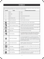
7=1&307
8LIJSPPS[MRKWMKREP[SVHWERHQIERMRKWEVIMRXIRHIHXSI\TPEMRXLIPIZIPWSJVMWOEWWSGMEXIH[MXLXLMWTVSHYGX
7=1&30
7-+2%0
1)%2-2+
(%2+)6
-RHMGEXIWERMQQMRIRXP]LE^EVHSYWWMXYEXMSR[LMGLMJRSXEZSMHIH[MPP
VIWYPXMRHIEXLSVWIVMSYWMRNYV]
;%62-2+
-RHMGEXIWETSXIRXMEPP]LE^EVHSYWWMXYEXMSR[LMGLMJRSXEZSMHIHGSYPH
VIWYPXMRHIEXLSVWIVMSYWMRNYV]
'%98-32
-RHMGEXIWETSXIRXMEPP]LE^EVHSYWWMXYEXMSR[LMGLMJRSXEZSMHIHQE]
VIWYPXMRQMRSVSVQSHIVEXIMRNYV]
'%98-32
;MXLSYX7EJIX]%PIVX7]QFSP-RHMGEXIWEWMXYEXMSRXLEXQE]VIWYPXMR
TVSTIVX]HEQEKI
7)6:-')
;%62-2+
7IVZMGMRKVIUYMVIWI\XVIQIGEVIERHORS[PIHKIERH
WLSYPHFITIVJSVQIHSRP]F]EUYEPMJMIHWIVZMGIXIGL
RMGMER*SVWIVZMGI[IWYKKIWX]SYVIXYVRXLITVSHYGXXS
XLIRIEVIWX%98,36->)(7)6:-')')28)6JSVVITEMV
;LIRWIVZMGMRKYWISRP]MHIRXMGEPVITPEGIQIRXTEVXW
8SEZSMHWIVMSYWTIVWSREPMRNYV]HSRSXEXXIQTXXSYWI
XLMWTVSHYGXYRXMP]SYVIEHXLSVSYKLP]ERHYRHIVWXERH
GSQTPIXIP]XLISTIVEXSV
WQERYEP7EZIXLMWSTIVEXSV
W
QERYEPERHVIZMI[JVIUYIRXP]JSVGSRXMRYMRKWEJISTIV
EXMSRERHMRWXVYGXMRKSXLIVW[LSQE]YWIXLMWTVSHYGX
;%62-2+
8LISTIVEXMSRSJER]TS[IVXSSPGERVIWYPXMRJSVIMKRSFNIGXWFIMRKXLVS[RMRXS]SYVI]IW[LMGLGERVI
WYPXMRWIZIVII]IHEQEKI&IJSVIFIKMRRMRKTS[IVXSSPSTIVEXMSREP[E]W[IEVWEJIX]KSKKPIWWEJIX]
KPEWWIW[MXLWMHIWLMIPHWSVEJYPPJEGIWLMIPH[LIRRIIHIH;IVIGSQQIRH;MHI:MWMSR7EJIX]1EWO
JSVYWISZIVI]IKPEWWIWSVWXERHEVHWEJIX]KPEWWIW[MXLWMHIWLMIPHW%P[E]WYWII]ITVSXIGXMSR[LMGL
MWQEVOIHXSGSQTP][MXL%27->
7%:)8,)7)-27869'8-327
7
SPEED AND WIRING
The no-load speed of the electric motor varies by model and
specification. The motor speed is not constant and decreases
under a load or with lower voltage. For voltage, the wiring
in a shop is as important as the motor’s horsepower rating.
A line intended only for lights cannot properly carry a power
tool motor. Wire that is heavy enough for a short distance will
be too light for a greater distance. A line that can support one
power tool may not be able to support two or three tools.
GROUNDING INSTRUCTIONS
This product must be grounded. In the event of an electrical
short circuit, grounding reduces the risk of electric shock
by providing an escape wire for the electric current. This
air compressor is equipped with an electric cord having an
equipment-grounding conductor and a grounding plug. The
plug must be plugged into a matching outlet that is properly
installed and grounded in accordance with all local codes and
ordinances.
Do not modify the plug provided. If it will not fit the outlet,
have the proper outlet installed by a qualified electrician.
WARNING:
Improper connection of the equipment-grounding
conductor can result in a risk of electric shock.
The conductor with insulation having an outer surface that
is green with or without yellow stripes is the equipmentgrounding conductor. If repair or replacement of the electric
cord or plug is necessary, do not connect the equipmentgrounding conductor to a live terminal.
Check with a qualified electrician or service personnel if the
grounding instructions are not completely understood, or if in
doubt as to whether the tool is properly grounded.
damaged
worncord
cord
immediately.
Replace
damage
ororworn
immediately.
Repair orareplace
a damaged
or
worn
cord immediately.
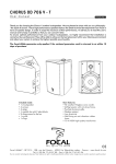
This product is for use on a nominal 120-V circuit and has
a grounding plug similar to the plug illustrated in Figure 1.
Only connect the product to an outlet having the same configuration as the plug. Do not use an adapter with this product.
.EVERUSEANELECTRICALADAPTORWITHTHISGROUNDEDPLUG
8
',/33!29/&4%2-3
0RESSURE3WITCH
!UTOMATICALLYCONTROLSTHEONOFFCYCLINGOFTHECOMPRES
SOR)TSTOPSTHECOMPRESSORWHENTHECUTOFFPRESSUREIN
THETANKISREACHEDANDSTARTSTHECOMPRESSORWHENTHE
AIRPRESSUREDROPSBELOWTHECUTINPRESSURE
03)0OUNDS0ER3QUARE)NCH
-EASUREMENTOFTHEPRESSUREEXERTEDBYTHEFORCEOFTHE
AIR4HEACTUALPSIISMEASUREDBYAPRESSUREGAUGEONTHE
COMPRESSOR
0UMP
0RODUCESTHECOMPRESSEDAIRWITHARECIPROCATINGPISTON
CONTAINEDWITHINTHECYLINDER
2EGULATOR0RESSURE'AUGE
$ISPLAYSTHECURRENTLINEPRESSURE,INEPRESSUREISADJUST
EDBYROTATINGTHEPRESSUREREGULATORKNOB
3AFETY6ALVE
0REVENTSAIRPRESSUREINTHEAIRTANKFROMRISINGOVERA
PREDETERMINEDLIMIT
3#&-3TANDARD#UBIC&EET0ER-INUTE
!UNITOFMEASUREOFAIRDELIVERY
4ANK0RESSURE'AUGE
)NDICATESTHEPRESSUREINTHEAIRTANK
4HERMAL/VERLOAD3WITCH
!UTOMATICALLYSHUTSOFFTHECOMPRESSORIFTHETEMPERATURE
OFTHEELECTRICMOTOREXCEEDSAPREDETERMINEDLIMIT
!IR&ILTER
0OROUSELEMENTCONTAINEDWITHINAMETALORPLASTICHOUS
INGATTACHEDTOTHECOMPRESSORCYLINDERHEADWHICH
REMOVESIMPURITYFROMTHEINTAKEAIROFTHECOMPRESSOR
!IR4ANK
#YLINDRICALCOMPONENTWHICHCONTAINSTHECOMPRESSEDAIR
#HECK6ALVE
$EVICETHATPREVENTSCOMPRESSEDAIRFROMFLOWINGBACK
FROMTHEAIRTANKTOTHECOMPRESSORPUMP
#UT)N0RESSURE
4HELOWPRESSUREATWHICHTHEMOTORWILLAUTOMATICALLY
RESTART
#UT/FF0RESSURE
4HEHIGHPRESSUREATWHICHTHEMOTORWILLAUTOMATICALLY
SHUTOFF
%LECTRIC-OTOR
$EVICEWHICHPROVIDESTHEROTATIONALFORCENECESSARYTO
OPERATETHECOMPRESSORPUMP
-ANUAL/N/FF3WITCH
#ONTROLWHICHTURNSTHEAIRCOMPRESSORONOROFF4HE
PRESSURESWITCHWILLNOTAUTOMATICALLYSTARTANDCONTROLTHE
COMPRESSORUNLESSTHEMANUAL/N/FF3WITCHISINTHE/.
LPOSITION
.04.ATIONAL0IPE4HREAD
.ATIONAL0IPE4HREADISA53STANDARDFORTAPERED.04
ORSTRAIGHT.03THREADSUSEDTOJOINPIPESANDFITTINGS
!THREADSEALINGTAPEMUSTBEUSEDTOPROVIDEALEAKFREE
SEALONPIPETHREADEDCONNECTIONS
0RESSURE2EGULATOR+NOB
2EGULATESTHEOUTGOINGPRESSUREFROMTHEAIROUTLETTOTHE
TOOL)TISPOSSIBLETOINCREASEORDECREASETHEPRESSUREAT
THEOUTLETBYADJUSTINGTHISCONTROLKNOB
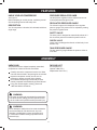
TOOLS NEEDED
The following tools are needed in order to assemble the wheel kit.
TWO
ADJUSTABLE WRENCHES
47/!$*534!",%72%.#(%3
9
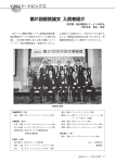
FEATURES
PRODUCT SPECIFICATIONS
Running Horsepower ................................................... 2 HP
Air Tank Capacity...................................................... 29 gal.
Air Pressure ....................................................150 PSI max.
Air Delivery ......................................... 7.3 SCFM @ 40 PSI
............................................................ 5.9 SCFM @ 90 PSI
Lubrication .......................................................................Oil
Gauges ....................................................... 1.5 in. diameter
Input.................................. 120 V, 60 Hz, AC only, 15 Amps
Net Weight ............................................................177.7 lbs.
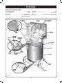
AIR INTAKE
FILTER
OIL FILL
PLUG
SAFETY GUARD
FOR THE V-BELT
ELECTRIC
MOTOR
CHECK
VALVE
SAFETY
VALVE
PRESSURE
SWITCH
(ON/OFF)
PRESSURE
REGULATOR
KNOB
ELECTRICAL
CABLE
HANDLE
TANK
PRESSURE
GAUGE
REGULATOR
PRESSURE
GAUGE
QUICK
COUPLER
TANK
RUBBER
FOOT
DRAIN
VALVE
WHEEL
Fig. 2
10
FEATURES
KNOW YOUR AIR COMPRESSOR
PRESSURE REGULATOR KNOB
See Figure 2.
Before attempting to use this product, familiarize yourself
with all operating features and safety rules.
Use the pressure regulator knob to adjust the amount of
air being delivered through the hose.
REGULATOR PRESSURE GAUGE
DESCRIPTION
The current line pressure is displayed on the regulator
pressure gauge. This pressure can be adjusted by rotating
the pressure regulator knob.
Your air compressor is aircooled, oil lubricated, belt-driven,
single stage.
SAFETY VALVE
The safety valve is designed to automatically release air if
the air receiver pressure exceeds the preset maximum.
CHECK VALVE
Check valves are designed to allow air to flow freely in one
direction only.
TANK PRESSURE GAUGE
The tank pressure gauge indicates the pressure of the air
in the tank.
ASSEMBLY
UNPACKING
PACKING LIST
This product has been shipped completely assembled,
except the two rubber feet and the two wheels.
Air Compressor (1)
Operator’s Manual (1)
Replacement Parts List (1)
Carefully remove the compressor from the box. Make
sure that all items listed in the packing list are included.
Inspect the compressor carefully to make sure no
breakage or damage occurred during shipping.
Do not discard the packing material until you have
carefully inspected and satisfactorily operated the tool.
If any parts are damaged or missing, please call
1-800-444-3353 for assistance.
WARNING:
If any parts are missing do not operate the compressor
or air tools until the missing parts are replaced. Failure
to do so could result in possible serious personal injury.
WARNING:
Do not attempt to modify this tool or create accessories
not recommended for use with this tool. Any such
alteration or modification is misuse and could result
in a hazardous condition leading to possible serious
personal injury.
11
ASSEMBLY
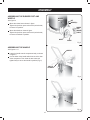
ASSEMBLING THE RUBBER FOOT AND
WHEELS
WASHER
NUT
See Figure 3.
Mount the rubber feet as shown in figure.
Tighten firmly with an open-end wrench (not included)
to secure it in position.
NUT
WASHER(s)
RUBBER
FOOT
WASHER
SCREW
Mount the wheels as shown in figure.
Tighten firmly with an open-end wrench (not included)
to secure the wheels in position.
WHEEL
SCREW
Fig. 3
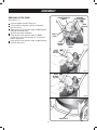
ASSEMBLING THE HANDLE
HANDLE
See Figures 4 - 5.
Lower the handle onto the compressor body, as shown
in Figure 4.
Line the holes of the handle with the ones on the slots
of the compressor. Then insert the two knobs and
tighten firmly to secure the handle in position (Fig. 5).
HOLE OF
THE ANDLE
Fig. 4
KNOB
Fig. 5
12
ASSEMBLY
PRESSURE SWITCH
(ON/OFF)
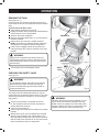
BREAKING IN THE PUMP
See Figures 6 - 9.
Check and tighten all bolts, fittings, etc.
Turn the pressure regulator knob fully clockwise to
open the air flow.
Place the lever of the pressure switch in ‘OFF’ position
and plug in the power cord.
Open the drain valve completely.
Place the lever of the pressure switch in ‘AUTO’
position and run the air compressor for 10 minutes to
break in pump parts.
Place the lever of the pressure switch in ‘OFF’ position.
Close the drain valve.
PRESSURE
REGULATOR KNOB
QUICK
COUPLER
SAFETY
VALVE
TANK
PRESSURE
GAUGE
REGULATOR
PRESSURE
GAUGE
Fig. 6
LEVER
IN ‘OFF’
POSITION
Fig. 7
LEVER
IN ‘AUTO’
POSITION
Fig. 8
DRAIN VALVE
13
Fig. 9
OPERATION
WARNING:
WARNING:
Do not allow familiarity with tools to make you careless.
Remember that a careless fraction of a second is
sufficient to inflict serious injury.
Your tool may require more air consumption than this
air compressor is capable of providing. Check the tool
manual to avoid damage to the tool or risk of personal
injury.
WARNING:
Following all safety precautions in this manual and the
manufacturer’s instructions in the air tool manual, you
may now proceed to use your air-powered tool.
If using an inflation accessory, control the amount of air
flow with the pressure regulator knob. Turning the knob
fully counterclockwise will completely stop the flow of
air.
NOTE: Always use the minimum amount of pressure
necessary for your application. Using a higher pressure
than needed will drain air from the tank more rapidly
and cause the unit to cycle on more frequently.
When finished, always drain the tank and unplug the
unit. Never leave the unit plugged in and/or running
unattended.
Always wear safety goggles or safety glasses with
side shields when operating power tools. Failure to do
so could result in objects being thrown into your eyes
resulting in possible serious injury.
CAUTION:
Do not use in an environment that is dusty or otherwise
contaminated. Using the air compressor in this type of
environment may cause damage to the unit.
APPLICATIONS
Air compressors are utilized in a variety of air system
applications. Match hoses, connectors, air tools, and
accessories to the capabilities of the air compressor.
You may use this tool for purposes listed below:
Operating some air-powered tools.
Inflating tires, air beds, sports equipment, etc.
USING THE AIR COMPRESSOR
See Figures 6 - 8.
Ensure tank drain is closed.
Ensure lever of the pressure switch is in the ‘OFF’
position and air compressor is unplugged.
Connect the air line to the quick coupler.
WARNING:
Always ensure the lever of the pressure switch is in the
‘OFF’ position and the regulator pressure gauge read
zero before changing air tools or disconnecting the
hose from the air outlet. Failure to do so could result in
possible serious personal injury.
Rotate regulator knob fully counterclockwise in order to
close the air flow.
Fill the compressor pump with oil. Do not overfill.
Connect the power cord to the power supply.
Place the lever of the pressure switch in ‘AUTO’
position, in order to switch on the compressor.
Rotate pressure regulator knob to desired line
pressure. Turning the knob clockwise increases
air pressure at the outlet; turning counterclockwise
reduces air pressure at the outlet.
14
OPERATION
DRAINING THE TANK
See Figures 10 - 11.
To help prevent tank corrosion and keep moisture out of
the air used, the tank of the compressor should be drained
daily.
A correct use of the drain valve:
Verify that the compressor is turned off.
Holding the handle, tilt the compressor toward the drain
valve so that it’s set in a lower position.
Open the drain valve completely.
Keep the compressor tilted (figure 11) until all moisture
has been removed.
Drain moisture from tank into a suitable container.
NOTE: Condensate is a polluting material and should
be disposed of in compliance with local regulations.
If drain valve is clogged, release all air pressure by
pulling the safety valve. Remove and clean valve, then
reinstall.
DRAIN VALVE
Fig. 10
WARNING:
Unplug the air compressor and release all air from
the tank before servicing. Failure to depressurize tank
before attempting to remove valve may cause serious
personal injury.
DRAIN VALVE
Fig. 11
SAFETY
VALVE
Turn off drain valve until completely closed.
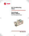
CHECKING THE SAFETY VALVE
See Figure 12.
WARNING:
Do not attempt to tamper with safety valve. Anything
loosened from this device could fly up and hit you.
Failure to heed this warning could result in death or
serious personal injury.
Fig. 12
The safety valve will automatically release air if the air
receiver pressure exceeds the preset maximum. The valve
should be checked before each day of use by pulling the
ring by hand.
WARNING:
If air leaks after the ring has been released, or if the
valve is stuck and cannot be actuated by the ring,
Do Not use the air compressor until the safety valve
has been replaced. Use of the air compressor in this
condition could result in serious personal injury.
Turn the air compressor on and allow the tank to
fill. The compressor will shut off when the pressure
reaches the preset maximum.
Turn the air compressor off.
Pull the ring on the safety valve to release air for twenty
seconds.
Release the ring. Air must immediately stop escaping
when the ring is released. Any continued loss of air
after releasing the safety valve ring indicates a problem
with the safety valve. Discontinue use and seek service
before continued use of the air compressor.
15
MAINTENANCE
CHECK THE OIL LEVEL AT REGULAR INTERVALS
WARNING:
See Figure 13.
Place the compressor on a level and straight surface. The
oil level must be between the two marks MAX and MIN on
the oil sight glass (fig. 13).
Changing the oil: use SAE 40 oil (for cold climates,
SAE 20 is recommended). Do not mix different grade
oils. If the oil changes color (whitish = presence of water;
dark = overheated), it is good practice to replace the oil
immediately.
It should be refilled for the first time after 100 hours of
operation. Thereafter the oil should be drained and refilled
after every 300 hours in service.
When servicing, use only identical Harbor Freight Tools
replacement parts. Use of any other parts may create a
hazard or cause product damage.
WARNING:
Always wear safety goggles or safety glasses with side
shields during power tool operation or when blowing
dust. If operation is dusty, also wear a dust mask.
WARNING:
Always release all pressure, disconnect from power
supply, and allow unit to cool to the touch before
cleaning or making repairs on the air compressor.
CHANGING THE OIL
See Figures 13 - 14.
Switch off the engine and pull the mains plug out of the
socket. After releasing any air pressure you can unscrew
the oil drain plug (fig. 13) from the compressor pump. To
prevent the oil from running out in an uncontrolled manner,
hold a small metal chute under the opening and collect the
oil in a vessel. If the oil does not drain out completely, we
recommend tilting the compressor slightly.
Dispose of the old oil at a drop-off point for old oil.
GENERAL MAINTENANCE
Humidity in the air causes condensate to form in the air
tank. This condensate should be drained daily and/or
every hour, using the instructions found in Draining the
Tank.
The safety valve automatically releases air if the air
receiver pressure exceeds the preset maximum. Check
the safety valve before each use following the instructions
found in Checking the Safety Valve.
Inspect the tank yearly for rust, pin holes, or other
imperfections that could cause it to become unsafe.
OIL
SIGHT
GLASS
Avoid using solvents when cleaning plastic parts. Most
plastics are susceptible to damage from various types of
commercial solvents and may be damaged by their use.
Use clean cloths to remove dirt, dust, oil, grease, etc.
OIL
DRAIN
PLUG
WARNING:
Do not at any time let brake fluids, gasoline, petroleumbased products, penetrating oils, etc., come in contact
with plastic parts. Chemical can damage, weaken or
destroy plastic which may result in serious personal
injury. Electric tools used on fiberglass material, wallboard, spackling compounds, or plaster are subject
to accelerated wear and possible premature failure
because the fiberglass chips and grindings are highly
abrasive to bearings, brushes, commutators, etc.
Consequently, we do not recommend using this tool for
extended work on these type of materials. However, if
you do work with any of these materials, it is extremely
important to clean the tool using compressed air.
Fig. 13
OIL
FILL
PLUG
Fig. 14
16
MAINTENANCE
When the oil has drained out, re-fit the oil drain plug (fig.
13). Fill new oil through the oil filler opening until it comes
up to the required level. Do not overfill. After topping up,
tighten the oil fill plug (fig. 14), making sure that there are
no leaks during use. Once a week, check the oil level to
assure proper lubrication.
SAFETY GUARD
FOR THE V-BELT
Fig. 15
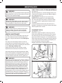
RETENSIONING THE V-BELT
See Figures 15 - 17.
Pull out the power plug and remove the safety guard for
the V-belt (figures 15 - 16).
Slacken the four motor fixing screws (figure 17).
Shift the motor until the V-belt is tensioned to the point
where it can still be depressed by approx. 0.4-0.8 in.
(1-2 cm) at the longest free position.
Retighten the motor fixing screws and refit the safety
guard for the V-belt.
SAFETY GUARD
FOR THE V-BELT
Fig. 16
0.4-0.8 in.
(1-2 cm)
V-BELT
MOTOR
UNIT
MOTOR FIXING SCREW
Fig. 17
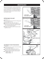
TIGHTENING OF HEAD TENSION RODS
HEAD
TENSION
ROD
See Figure 18.
Check that all screws (in particular those of the head of
the unit) are tightly drawn up.
The check must be carried out prior to the first
compressor starting. And after the first hour of work.
Tightening values for the tension rods of the head:
Nm min. torque = 22
Nm max. torque = 27
Fig. 18
17
MAINTENANCE
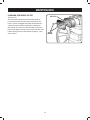
CLEANING THE INTAKE FILTER
AIR FILTER
See Figure 19.
The intake filter prevents dust and dirt being drawn in.
It is essential to clean this filter after at least every 100
hours in service. A clogged intake filter will decrease the
compressor’s performance dramatically. Undo the two
allen screws. You can then remove the filter from the two
halves of the plastic housing, tap it to remove the dirt, blast
it down with low-pressure compressed air (approx. 3 bar)
and re-insert it.
ALLEN
SCREWS
Fig. 19
18
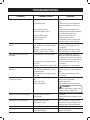
TROUBLESHOOTING
Problem
Compressor will not run
Possible Cause
Loss of power or overheating
No electrical power
Blown shop/house fuse
Shop/house breaker open
Thermal overload open
Pressure switch bad
Tank is full of air
Solution
Check for proper use of extension
cord
Check to be sure unit is plugged in
Check fuse/breaker or motor overload
Replace shop/house blown fuse
Reset shop/house breaker, determining why problem happened
Motor will restart when cool
Replace pressure switch
Compressor will turn on when tank
pressure drops to cut-in pressure
Motor hums but cannot run or runs
slowly
Low voltage
Wrong gauge wire or length of extension cord
Shorted or open motor winding
Defective check valve or unloader
Check with voltmeter
Check for proper gauge wire and
cord length
Take compressor to service center
Take compressor to service center
Fuses blow/circuit breaker trips
repeatedly
Incorrect size fuse, circuit overload
Wrong gauge wire or length of extension cord
Defective check valve or under loader
Check for proper fuse, use timedelay fuse, disconnect other electrical appliances from circuit or operate
compressor on its own branch circuit
Check for proper gauge wire and
cord length
Take compressor to service center
Thermal overload protector cuts out
repeatedly
Low voltage
Lack of proper ventilation/room temperature too high
Wrong gauge wire or length of extension cord
Check with voltmeter
Move compressor to well-ventilated
area
Check for proper gauge wire and
cord length
Air receiver pressure drops when
compressor shuts off
Loose connections (fittings, tubing,
etc.)
Loose drain valve
Check valve leaking
Check all connections with soap and
water solution and tighten
Tighten drain valve
Take compressor to service center
DANGER:
Do not disassemble check valve
with air in tank — bleed tank.
Excessive moisture in discharge air
Excessive water in air tank
High humidity
Drain tank
Move to area of less humidity; use air
line filter
Compressor runs continuously
Defective pressure switch
Excessive air usage
Take compressor to service center
Decrease air usage; compressor not
large enough for tool’s requirement
Compressor vibrates
Loose mounting bolts
Tighten mounting bolts
Air output lower than normal
Broken inlet valves
Connections leaking
19
Take compressor to service center
Tighten connections
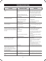
TROUBLESHOOTING
Problem
Air leak from the valve of the pressure
switch
Reduction of efficiency, frequent startup. Low pressure values
The motor and/or the compressor
overheat irregularly
After an attempt to start the
compressor, it stops due to tripping of
the thermal cutout caused by forcing of
the motor
During operation, the compressor
stops for no apparent reason
When operating, the compressor
vibrates and the motor emits an
irregular buzzing sound. If it stops, it
does not restart although the sound of
the motor is present
Possible Cause
Check valve does not perform its
Unscrew the hex-shaped head of the
function correctly due to wear or dirt on check valve, clean the housing and the
the seal
special rubber disk (replace if worn).
Re-assembler and tighten carefully
Condensate drainage cock open
Close the condensate drainage cock
Rilsan hose not inserted correctly in
pressure switch
Insert the Rilsan hose correctly inside
the pressure switch
Excessively high consumption
Decrease the demand of compressed
air
Leaks from joints and/or pipes
Change gaskets
Clogging of the suction filter
Clean/replace the suction filter
Slipping of the belt
Check V-belt tension
Insufficient ventilation
Improve ambient conditions
Closing of air ducts
Check and if necessary clean the air
filter
Insufficient lubrication
Top up or change oil
Start-up with head of the compressor
charged
Release the compressor head by using
the pressure switch push button
Low temperature
Improve ambient conditions
Voltage too low
Check that the mains voltage matches
that of the dataplate. Eliminate any
extensions
Incorrect or insufficient lubrication
Check level, top up and if necessary
change the oil
Inefficient electrovalve
Take compressor to the service center
Tripping of the thermal cutout of the
motor
Check level oil
Electric fault
Take compressor to the service center
Faulty capacitor
Have the capacitor replaced
Irregular presence of oil in the network Too much oil inside the unit
Leaking of condensate from the vent
cock
Solution
Operate on the lever of the pressure
switch returning this to the OFF
position.
Reset the thermal cutout and restart.
If the fault persists, take the
compressor to the service center
Check oil level
Wear on segments
Take compressor to the service center
Presence of dirt/grit inside the cock
Clean the cock
20
NOTES
21
LIMITED 1 YEAR / 90 DAY WARRANTY
Harbor Freight Tools Co. makes every effort to assure that its products meet
high quality and durability standards, and warrants to the original purchaser that for a
period of one year from date of purchase that the tank is free of defects in materials
and workmanship (90 days if used by a professional contractor or if used as rental
equipment). Harbor Freight Tools also warrants to the original purchaser, for a period of
ninety days from date of purchase, that all other parts and components of the product
are free from defects in materials and workmanship. This warranty does not apply to
damage due directly or indirectly to misuse, abuse, negligence or accidents, repairs or
alterations outside our facilities, normal wear and tear, or to lack of maintenance. We
shall in no event be liable for death, injuries to persons or property, or for incidental,
contingent, special or consequential damages arising from the use of our product.
Some states do not allow the exclusion or limitation of incidental or consequential
damages, so the above limitation of exclusion may not apply to you. THIS WARRANTY
IS EXPRESSLY IN LIEU OF ALL OTHER WARRANTIES, EXPRESS OR IMPLIED,
INCLUDING THE WARRANTIES OF MERCHANTABILITY AND FITNESS.
To take advantage of this warranty, the product or part must be returned to us
with transportation charges prepaid. Proof of purchase date and an explanation of the
complaint must accompany the merchandise. If our inspection verifies the defect, we
will either repair or replace the product at our election or we may elect to refund the
purchase price if we cannot readily and quickly provide you with a replacement. We will
return repaired products at our expense, but if we determine there is no defect, or that
the defect resulted from causes not within the scope of our warranty, then you must
bear the cost of returning the product.
This warranty gives you specific legal rights and you may also have other rights
which vary from state to state.
3491 Mission Oaks Blvd. • PO Box 6009 • Camarillo, CA 93011 • (800) 444-3353
WARNING:
The brass components of this product contain lead, a
chemical known to the state of California to cause birth
defects (or other reproductive harm).
(California health & safety code § 25249.5, et seq.)
For technical questions, please call 1-800-444-3353.
9039388/B
67696
SKU 68127
Portable Air Compressor
Model No. 68127
Replacement Parts List
Ver. 2010.12
2
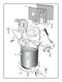
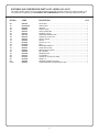
PORTABLE AIR COMPRESSOR PARTS LIST− MODEL NO. 68127
The model number will be found on a plate attached to air tank. Always mention the model number in all
correspondence regarding your PORTABLE AIR COMPRESSOR or when ordering replacement parts.
KEY NO.
CODE
DESCRIPTION
023
101
104
105
106
107
108
109
110
112
125
126
131
132
135
142
145
300
500
501
502
PUMP
2881000
9413387021
9083910
9048003
9047061
9047051
9051143
9052130
9049115
9053003
9076080
9075036
9416728
9065301
844F001
838000A
9043348
9420719
9416774
9416769
9083296
2800070
AIR FILTER...................................................................................................1
TANK 29 GAL ...............................................................................................1
HANDLE .......................................................................................................1
CHECK VALVE .............................................................................................1
QUICK COUPLING.......................................................................................1
TAP BALL VALVE .........................................................................................1
PRESSURE REGULATOR ...........................................................................1
GAUGE 50 1/4 RAD CPI ..............................................................................1
SAFETY VALVE ............................................................................................1
NIPPLE .........................................................................................................1
PULLEY 90 x 1A ...........................................................................................1
BELT .............................................................................................................1
PRESSURE SWITCH ...................................................................................1
CORD WITH PLUG ......................................................................................1
MOTOR HP2 M 120/60 ................................................................................1
BELT GUARD ...............................................................................................1
SENDING PIPE ............................................................................................1
KIT WHEELS ................................................................................................1
GAUGE 50 1/4 RAD CPI LONG ...................................................................1
KNOB L15.....................................................................................................1
SUPPORT FOR BELT GUARD ....................................................................1
PUMP B2800 WITH AFTERCOOLER 180°..................................................1
3
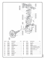
Q.TY
CODE
DESCRIPTION
Q.TY
001
002
003
004
005
006
008
012
014
015
016
017
018
023
024
026
027
029
030
2860101
2830001
3860400
2860200
2660500
2840050
2810100
1421100
3021200
9140040
9020011
9020041
9020071
2881000
2870100
2060690
2060500
2600100
9170030
CRANKCASE....................................1
CYLINDER ........................................1
HEAD ................................................1
CRANKSHAFT..................................1
CRANKCASE BOTTOM ...................1
ASS.VALVE PLATE...........................1
CONROD ..........................................2
PISTON.............................................2
PISTON PIN......................................2
SNAP RING ......................................4
SEAL AC ...........................................2
SEAL ROS ........................................2
SEAL ROF ........................................2
AIR FILTER .......................................1
AFTERCOOLER ...............................1
COVER LOV .....................................1
COVER LV ........................................1
FLYWHEEL .......................................1
BEARING ..........................................2
4
KEY NO.
CODE
DESCRIPTION
Q.TY
032
033
034
035
036
060
061
062
064
065
066
501
502
503
504
505
506
507
9022001
9024029
9163010
9110014
9004008
2650101
2850200
2850300
2850400
2050500
1070200
9101144
9415853
9411090
9101594
9101094
9101034
9162020
OIL LEVEL ......................................... 1
BREATHER........................................ 1
GASKET ............................................ 1
SCREW.............................................. 1
WASHER ........................................... 1
GASKET CRANKCASE ..................... 1
GASKET CRANKCASE-CYLINDER.. 1
GASKET CYLINDER-VALVE PLATE . 1
GASKET VALVE PLATE-HEAD ......... 1
GASKET COVER............................... 2
GASKET AFTERCOOLER................. 1
SCREW.............................................. 2
SCREW.............................................. 2
SCREW............................................ 12
SCREW.............................................. 6
SCREW.............................................. 8
SCREW.............................................. 1
WASHER ........................................... 1
9039394/A
KEY NO.