1
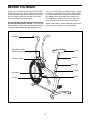
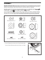
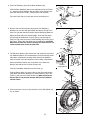
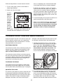
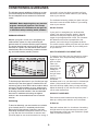
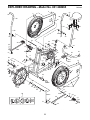
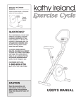
USERÕS MANUAL
Model No. 831.288265
Serial No.
_
Write the serial number in the space
above for future reference.
Serial
Number
Decal
Patent Pending
CAUTION
Read all precautions and instructions in this manual before using
this equipment. Keep this manual
for future reference.
SEARS, ROEBUCK AND CO., HOFFMAN ESTATES, IL 60179
TABLE OF CONTENTS
IMPORTANT PRECAUTIONS . . . . . . . . . . . . . . . . . . . . . . . . . . . . . . . . . . . . . . . . . . . . . . . . . . . . . . . . . . . . .2
BEFORE YOU BEGIN . . . . . . . . . . . . . . . . . . . . . . . . . . . . . . . . . . . . . . . . . . . . . . . . . . . . . . . . . . . . . . . . . . .3
ASSEMBLY . . . . . . . . . . . . . . . . . . . . . . . . . . . . . . . . . . . . . . . . . . . . . . . . . . . . . . . . . . . . . . . . . . . . . . . . . . .4
HOW TO USE THE EXERCISE CYCLE . . . . . . . . . . . . . . . . . . . . . . . . . . . . . . . . . . . . . . . . . . . . . . . . . . . . . .7
TROUBLE-SHOOTING AND MAINTENANCE . . . . . . . . . . . . . . . . . . . . . . . . . . . . . . . . . . . . . . . . . . . . . . . . .8
CONDITIONING GUIDELINES . . . . . . . . . . . . . . . . . . . . . . . . . . . . . . . . . . . . . . . . . . . . . . . . . . . . . . . . . . . . .9
PART LIST . . . . . . . . . . . . . . . . . . . . . . . . . . . . . . . . . . . . . . . . . . . . . . . . . . . . . . . . . . . . . . . . . . . . . . . . . . .10
EXPLODED DRAWING . . . . . . . . . . . . . . . . . . . . . . . . . . . . . . . . . . . . . . . . . . . . . . . . . . . . . . . . . . . . . . . . .11
ORDERING REPLACEMENT PARTS . . . . . . . . . . . . . . . . . . . . . . . . . . . . . . . . . . . . . . . . . . . . . . . .Back Cover
FULL 90 DAY WARRANTY . . . . . . . . . . . . . . . . . . . . . . . . . . . . . . . . . . . . . . . . . . . . . . . . . . . . . . .Back Cover
IMPORTANT PRECAUTIONS
WARNING: To reduce the risk of serious injury, read the following important precautions before
using the LIFESTYLER¨ DT1000.
through the seat post. Do not insert the seat
knob under the seat post. Tighten the seat
knob into the welded nut.
1. It is the responsibility of the owner to ensure
that all users of the DT1000 are adequately
informed of all warnings and precautions.
10. Always sit on the seat when using the
DT1000; never stand up on the pedals.
2. Read all instructions in this manual before
using the DT1000. Use the DT1000 only as
described.
11. If you feel faint, dizzy, or short of breath, stop
immediately and begin cooling down.
3. Place the DT1000 on a level surface. Place a
mat beneath the DT1000 to protect the floor.
12. The DT1000 is intended for home use only.
Do not use the DT1000 in a commercial,
rental or institutional setting.
4. Inspect and tighten all parts regularly. Make
sure that the chain is properly adjusted (see
MAINTENANCE AND TROUBLE-SHOOTING
on page 8). Replace worn parts immediately.
13. The decal shown below has been placed on
the DT1000. If the decal is missing, or if it is
not legible, please call our toll-free HELPLINE
to order a free replacement decal (see the
back cover of this manual). Apply the decal
in the location shown.
5. Keep children under age 12 and pets away
from the DT1000 at all times.
6. The DT1000 should not be used by persons
weighing more than 250 pounds.
7. Keep hands and feet away from the link arms
and other moving parts.
8. Do not wear loose clothing that could
become caught on the DT1000. Always
wear athletic shoes for foot protection.
9. When adjusting the seat, insert the seat knob
through the welded nut on the frame and
WARNING: Before beginning this or any exercise program, consult your physician. This is especially
important for persons over the age of 35 or persons with pre-existing health problems. Read all
instructions before using. SEARS assumes no responsibility for personal injury or property damage
sustained by or through the use of this product.
2
BEFORE YOU BEGIN
Thank you for selecting the innovative LIFESTYLER¨
DT1000 exercise cycle. The DT1000 blends advanced
engineering with contemporary styling to provide you
with a low-impact, total body workout in the convenience and privacy of your own home.
until 7 p.m. Central Time (excluding holidays). To help
us assist you, please note the product model number
and serial number before calling. The model number is
831.288265. The serial number can be found on a
decal attached to the exercise cycle (see the front
cover of this manual for the location of the decal).
For your benefit, read this manual carefully before
you use the LIFESTYLER¨ DT1000. If you have additional questions, please call our toll-free HELPLINE at
1-800-736-6879, Monday through Saturday, 7 a.m.
Before reading further, please familiarize yourself with
the parts that are labeled in the drawing below.
Handlebar
Water Bottle Holder
(Bottle not included)
Seat
Seat Post
Electronic Monitor
Seat Knob
Frame
Side Shield
Pedal
Link Arm
3
ASSEMBLY
Assembly requires two people. Place all parts of the exercise cycle in a cleared area and remove the packing
materials. Do not dispose of the packing materials until assembly is completed. Read through all steps before
beginning. During assembly, make sure that all parts are oriented as shown in the drawings.
Assembly requires the included tool and grease packet as well as an adjustable wrench
a rubber mallet
, and a phillips screwdriver
.
,
Use the drawings below to identify the small hardware used in assembly. The number in parenthesis beneath
each part refers to the key number of the part, from the PART LIST on page 10. The second number refers to
the quantity used in assembly. Note: some of the hardware shown below may have been pre-attached.
M8 Spring Washer (3)Ð4
M8 Locknut (32)-8
M8 Washer (5)-4
1/2" Locknut (23)-2
3/8" Push Cap (19)-2
5/8" Push Cap (35)-2
M6 x 16 Screw (49)-8
3/16Ó Small Screw (2)Ð15
Link Arm Bushing (47)-2
Pedal Bushing (25)-2
M6 x 9mm Screw (66)-1
1. Press an Endcap (40) onto each of the Frame Extensions (65).
1
Press the Frame Extensions (65) into the Frame (1) as shown.
40
65
1
65
40
4
2. Press two Endcaps (40) onto the Rear Stabilizer (39).
2
40
Slide the Rear Stabilizer (39) into the indicated end of the Frame
(1). Attach the Rear Stabilizer with two M6 x 16mm Screws (49)
from each side and four M6 x 16mm Screws from beneath.
40
39
Tap a 3/8Ó Push Cap (19) onto each end of the locking rod.
49
49
1
3. Remove the four M8 Locknuts (32) and the four M8 Spring
Washers (3) from the Seat (48). Attach the Seat to the top of the
Seat Post (42) with the M8 Locknuts and the M8 Spring Washers.
19
3
48
Adjust the Seat (48) to the desired height. Insert the Seat Knob
(52) through the welded nut on the Frame (1) and through the
Seat Post (42). Next, press the Frame Bushing (43) into the top of
the Frame. Tighten the Seat Knob into the welded nut. CAUTION:
Make sure to insert the Seat Pin through the Seat Post; do not
insert the Seat Knob under the Seat Post.
3
32
3
32
3
42
43
52
1
4. The Electronic Monitor (46) requires two "AA" batteries (not included). Alkaline batteries are recommended. Find the markings inside
the battery compartment showing which direction the batteries
must be turned. Insert the batteries into the battery compartment.
4
46
46
27
Attach the Monitor Bracket (27) to the back of the Electronic
Monitor (46) with the four Console Screws (44).
Battery
Compartment
44
44
Insert the Handlebar Shaft (54) into the Frame (1).
46
Plug the Sensor Wire (21) into the wire on the Electronic Monitor
(46). Attach the Monitor Bracket (27) and the Monitor (46) to the
Frame (1) with two 3/16Ó Small Screws (2). Make sure that the
Sensor Wire is not pinched between the Electronic Monitor
and the Frame.
21
1
27
2
54
5. Press an Access Cover (14) into the hole in each Side Shield (50,
51) as shown.
5
50
14
51
5
6. Lubricate the Handlebar Shaft (54). Slide the Right Handlebar (36)
onto the right end of the Handlebar Shaft. (Note: Refer to the
drawing on the front cover and make sure that the Right
Handlebar is turned correctly.) Slide the Left Handlebar (37)
onto the left end of the Handlebar Shaft. Tap a 5/8" Push Nut (35)
onto each end of the Handlebar Shaft.
6
35
36
37
Refer to the inset drawing. Tighten the M6 x 9mm Screw (66) into
the Frame (1).
54
35
1
66
7. Slide an M8 Washer (5), a Link Arm Bushing (47) and a Link
Arm (26) onto the threaded pin on the lower end of the Left
Handlebar (37). Make sure that the Link Arm Bushing is
turned so the flange is next to the Washer. In addition, make
sure that the opening in the end of the Link Arm is downward, as shown. Tighten an M8 Locknut (32) with an M8
Washer (5) onto the threaded pin.
7
37
26
Flange
5
Attach the other Link Arm to the Right Handlebar (not shown) in
the same manner.
47
5
32
8. For your convenience, the pedal assemblies have been pre-assembled. Remove the 1/2" Locknut (23) from
one of the Pedal Shafts (16). Slide the 17.5mm Washer (56) onto the shoulder of the Pedal Shaft and firmly
tighten the Pedal Shaft clockwise into the right arm of the Crank (18). Next, tighten the 1/2Ó Locknut (23)
back onto the Pedal Shaft. Make sure that the 17.5mm Washer (56) can be moved back and forth on the
shoulder of the Pedal Shaft. Fit the end of the right Link Arm (26) onto the Pedal Shaft and slide the Link
Arm onto the Pedal Bushing (25).
Attach the other pedal assembly to the left arm of the Crank (not shown) in the same manner.
8
Shoulder
56
25
16
18
23
26
9. Make sure that all parts are properly tightened before you use the exercise cycle. Note: Some small
hardware may be left over after the exercise cycle is assembled.
6
HOW TO USE THE EXERCISE CYCLE
HANDLEBAR OPERATION
SEAT ADJUSTMENT
The handlebars can be used in either the stationary
mode, for pedaling exercise only, or the dual-action
mode, for both upper-body and lower-body exercise.
Proper seat
height is impor48
tant for effective
exercise. As you
pedal, there
42
should be a
52
slight bend in
1
your knees when
the pedals are in
the lowest position. To adjust
the Seat (48), dismount the exercise cycle, hold the
Seat, and remove the Seat Knob (52). Raise or lower
the Seat and insert the Seat Knob through the Frame
(1) and the Seat Post (42). Tighten the Seat Knob into
the welded nut on the Frame. CAUTION: Make sure
to insert the Seat Pin through the Seat Post; do
not insert the Seat Knob under the Seat Post.
STATIONARY MODE
To convert the
1
handlebars to
the stationary
mode, the Link
56
Arms (26) must
25
be disconnected from the
26
pedals. Pull the
Link Arms outward against
the 17.5mm
Washers (56),
until the Link
2
Arms are free
of the Pedal
Bushings (25).
26
CAUTION: Be
careful not to
pinch your
Locking Rod
fingers. Lift
the Link Arms
off the pedals.
Clip the Link Arms (26) onto the lock rod as shown in
drawing 2.
ELECTRONIC MONITOR OPERATION
The electronic monitor offers five modes to provide
instant exercise feedback:
SpeedÑ
Displays
your pedaling speed, in
miles per
hour.
DUAL-ACTION MODE
TimeÑ
Displays the
elapsed
time. Note:
Time will be
counted only
while you are pedaling. If you stop pedaling for ten
seconds or longer, the time mode will pause.
To convert the handlebars to the dual-action mode, the
Link Arms must be connected to the pedals. Refer to
drawing 2 above. Lift the Link Arms (26) off the lock rod.
Next, refer to drawing 1 above. Pull the Link Arms (26)
outward against the tops of the 17.5mm Washers (56),
while pulling against the bottoms of the Washers with
your fingers. CAUTION: Be careful not to pinch your
fingers. Slide the Link Arms onto the Pedal Bushings
(25). It may be helpful to move the link arms up and
down slightly until they slide onto the Pedal Bushings.
CAUTION: Make sure that the Link Arms are on the
Pedal Bushings. If the Link Arms are not on the
Pedal Bushings, the Link Arms may slip off during
use, resulting in injury to the user.
DistanceÑDisplays the total distance you have pedaled, in miles.
CalorieÑDisplays the approximate number of Calories
you have burned.
ScanÑDisplays the speed, time, distance and calorie
modes in a repeating cycle.
Note: The electronic monitor requires two "AA" batteries (not included). See assembly step 3 on page 4 for
battery installation instructions.
7
each, in a repeating cycle. A second mode indicator will show which mode is currently displayed.
Follow the steps below to use the electronic monitor:
1. To turn on the power, press the on/off button or
simply begin pedaling.
B. Speed, time, distance or calorieÑTo stop the
scan mode and select the speed, time, distance or
calorie mode for continuous display, repeatedly
press the mode button. Make sure that there is not
a mode indicator by the word ÒSCAN.Ó The modes
will be selected in the following order: speed, time,
distance, calorie, scan.
2. Select one of the five modes:
A. ScanÑ
Mode indicators
When the
power is
turned on,
the scan
mode will
be selected automatically.
A mode
indicator
will appear
by the
word "SCAN." The speed, time, distance and calorie modes will all be displayed, for five seconds
3. To reset the display, turn the power off and then on
again by pressing the on/off button twice.
4. When you are finished exercising, press the on/off
button to turn off the power. Note: If the pedals
are not moved and the buttons are not pressed
for four minutes, the power will turn off automatically in order to conserve the batteries.
TROUBLE-SHOOTING AND MAINTENANCE
Inspect and tighten all parts of the exercise cycle regularly. To clean the exercise cycle, use a damp cloth
and mild detergent. Never use abrasives or solvents;
keep liquid away from the console.
damaged. If the chain causes excessive noise or slips
as you pedal, check the chain in the following way:
1. Carefully pry the Access Cover (14) off the right
side shield. Reach into the access hole and press
down on the chain. There should be no more
than 1 inch, and no less than 1/4 inch, of vertical movement in the center of the chain. If the
chain is properly adjusted, reattach the Access
Cover. If the chain needs to be adjusted, see step 2.
ELECTRONIC MONITOR
If the electronic monitor does not function properly, the
batteries should be replaced. Most problems are the
result of drained batteries. See assembly step 4 on
page 5 for battery installation instructions.
If the electronic monitor still does not function properly,
the sensor wire should be checked. See assembly step
4 on page 5. Slide the electronic monitor off the frame
and make sure that the sensor wire is plugged fully
into the wire on the electronic monitor.
14
TIGHTENING THE PEDALS
4
If the pedals become loose, tighten the pedal shafts
into the arms of the crank. Tighten the 1/2Ó Locknuts
onto the pedal shafts (see assembly step 7 on page 6).
8
ADJUSTING THE CHAIN
2. Pry the Access Cover (14) off the left side shield.
Loosen the M8 Washer Nuts (4). To tighten the
chain, turn the M6 Adjustment Nuts (8) clockwise;
to loosen the chain, turn the Adjustment Nuts counterclockwise. Make sure that the fan is straight,
tighten the Fan Nuts and reattach the Access Covers.
The exercise cycle features a precision chain that must
be kept properly lubricated and adjusted. Apply a few
drops of light multi-purpose oil to the chain every three
months. If the chain is too tight, the bearings may be
damaged; if the chain is too loose, the fan may be
8
CONDITIONING GUIDELINES
The following general guidelines will help you to plan
your exercise program. Remember that proper nutrition and adequate rest are essential for successful
results.
your goal is to burn fat, adjust your pace until your
heart rate is near the lowest number in your training
zone as you exercise.
For maximum fat burning, adjust your pace until your
heart rate is near the middle number in your training
zone as you exercise.
WARNING: Before beginning this or any exercise
program, consult your physician. This is especially important for individuals over the age of 35
or individuals with pre-existing health problems.
Aerobic Exercise
If your goal is to strengthen your cardiovascular
system, your exercise must be Òaerobic.Ó Aerobic
exercise is activity that requires large amounts of
oxygen for prolonged periods of time. This increases
the demand on the heart to pump blood to the
muscles, and on the lungs to oxygenate the blood.
For aerobic exercise, adjust your pace until your heart
rate is near the highest number in your training zone
as you exercise.
EXERCISE INTENSITY
Whether your goal is to burn fat or strengthen your
cardiovascular system, the key to achieving the
desired results is to exercise with the proper intensity.
The proper intensity level can be found by using your
heart rate as a guide. The chart below shows recommended heart rates for fat burning, maximum fat burning, and cardiovascular (aerobic) exercise.
HOW TO MEASURE YOUR HEART RATE
To measure your heart rate, first exercise for at least
four minutes. Then, stop exercising and place two
fingers on your
wrist as shown.
Take a sixsecond heartbeat count, and
multiply the
result by 10 to
find your heart
rate. For
example, if your
six-second
heartbeat count is 14, your heart rate is 140 beats per
minute. (A six-second count is used because your
heart rate will drop rapidly when you stop exercising.)
Adjust the intensity of your exercise until your heart
rate is at the desired level.
To find the proper heart rate for you, first find your age
near the top of the chart (ages are rounded off to the
nearest ten years). Next, find the three numbers below
your age. The three numbers are your Òtraining zone.Ó
The lowest number is the recommended heart rate for
fat burning; the middle number is the recommended
heart rate for maximum fat burning; the highest
number is the recommended heart rate for aerobic
exercise.
WORKOUT GUIDELINES
Each workout should include three important parts: a
warm-up, training zone exercise, and a cool-down.
Fat Burning
A Warm-up
To burn fat effectively, you must exercise at a relatively low intensity level for a sustained period of time.
During the first few minutes of exercise, your body
uses easily accessible carbohydrate calories for energy. Only after the first few minutes of exercise does
your body begin to use stored fat calories for energy. If
Start each workout with 5 to 10 minutes of stretching
and light exercise. A proper warm-up increases your
body temperature, heart rate, and circulation in preparation for strenuous exercise.
9
Training Zone Exercise
Exercise Frequency
After warming up, increase the intensity of your
exercise until your heart rate is in your training zone
for 20 to 30 minutes. Note: During the first few weeks
of your exercise program, do not keep your heart rate
in your training zone for longer than 20 minutes.
To maintain or improve your condition, complete three
workouts each week, with at least one day of rest
between workouts. After a few months of regular
exercise, you may complete up to five workouts each
week if desired.
A Cool-down
The key to success is to make exercise a regular and
enjoyable part of your everyday life.
Finish each workout with 5 to 10 minutes of stretching.
This will increase the flexibility of your muscles and
will help to prevent post-exercise problems.
PART LISTÑModel No. 831.288265
Key
No.
Qty.
Description
1
2
3
4
5
6
7
8
9
10
11
12
13
14
15
16
17
18
19
20
21
22
23
24
25
26
27
28
29
30
31
32
33
34
1
15
4
2
4
1
3
2
2
2
1
1
1
2
1
2
1
1
2
3
1
1
2
2
2
2
1
1
2
2
2
8
2
4
Frame
3/16" Screw
M8 Spring Washer
M8 Washer Nut
M8 Washer
Reed Switch Clamp
Flange Bushing
M6 Adjustment Nut
M6 x 51mm Adjustment Bolt
Adjustment Bracket
Fan Axle Shaft
Fan Assembly
Pedal Spacer
Access Cover
Sprocket
Pedal Shaft
Chain
Crank
3/8Ó Push Cap
M4 x 16 Tapping Screw
Reed Switch/Sensor Wire
Short Spacer
1/2" Locknut
13mm Washer
Pedal Bushing
Link Arm
Monitor Bracket
Crank Assembly
21mm Washer
Pedal
M8 Pedal Washer
M8 Locknut
Pedal Cap
Handlebar Bushing
R0700A
Key
No.
Qty.
35
36
37
38
39
40
41
42
43
44
45
46
47
48
49
50
51
52
53
54
55
56
57
58
59
60
61
62
63
64
65
66
#
#
2
1
1
2
1
4
1
1
1
4
1
1
2
1
8
1
1
1
1
1
2
2
4
2
2
3
1
1
1
2
2
1
1
1
Description
5/8" Push Cap
Right Handlebar
Left Handlebar
Handlebar Foam
Rear Stabilizer
Endcap
Base Bumper
Seat Post
Frame Bushing
Console Screw
Long Spacer
Electronic Monitor
Link Arm Bushing
Seat
M6 x 16mm Screw
Right Side Shield
Left Side Shield
Seat Knob
Sensor Magnet
5/8Ó Handlebar Shaft
Pedal Spring
17.5mm Washer
Handlebar Endcap
M10 Flat Washer
M8 Hex Nut
M4 x 25mm Tapping Screw
Fan Plate
Fan Sprocket
Seat Post Bushing
21mm Flat Washer
Frame Extension
M6 x 9mm Screw
Grease Pack
User's Manual
Note: Ò#Ó indicates a non-illustrated part. Specifications are subject to change without notice. See the back cover
of this manual for information about ordering replacement parts.
10
EXPLODED DRAWINGÑModel No. 831.288265
R0700A
2
57
2
57
38
38
50
48
14
3
3
37
32
36
32
34
35
35
52
30
13
46
32
5
42
43
54
2
27
63
20
23
40
66
26
6
28
44
57
4
20
15
53
21
17
9
64
45
59
8
58
10
40
39
18
41
49
51
20
49
62
40 65
23 49
1
60
2
19
2
14
65
61
2
58
40
7
22
12
2
59
2
64
13
25
11
28
24
37
29
26
56
5
57
5
47
11
55
16
31
33
30
32
32
The model number and serial number of your LIFESTYLER¨
DT1000 are listed on a decal attached to the frame. See the front
cover of this manual to find the location of the decal.
Model No. 831.288265
QUESTIONS?
If you find that:
¥ you need help assembling or
operating the LIFESTYLER¨
DT1000
¥ a part is missing
All replacement parts are available for immediate purchase or
special order when you visit your nearest SEARS Service Center.
To request service or to order parts by telephone, call the toll-free
numbers listed at the left.
When requesting help or service, or ordering parts, please be
prepared to provide the following information:
¥ The NAME OF THE PRODUCT (LIFESTYLER¨ DT1000)
¥ or you need to schedule repair
service
call our toll-free HELPLINE
1-800-736-6879
MondayÐSaturday, 7 amÐ7 pm
Central Time (excluding holidays)
¥ The MODEL NUMBER OF THE PRODUCT (831.288265)
¥ The KEY NUMBER OF THE PART (see page 10)
¥ The DESCRIPTION OF THE PART (see page 10).
REPLACEMENT
PARTS
If parts become worn and need
to be replaced, call the following
toll-free number
1-800-FON-PART
(1-800-366-7278)
FULL 90 DAY WARRANTY
For 90 days from the date of purchase, if failure occurs due to defect in material or workmanship in this
SEARS BIKE EXERCISER, contact the nearest SEARS Service Center throughout the United States
and SEARS will repair or replace the BIKE EXERCISER, free of charge.
This warranty does not apply when the BIKE EXERCISER is used commercially or for rental purposes.
This warranty gives you specific legal rights, and you may also have other rights which vary from state
to state.
SEARS, ROEBUCK AND CO., DEPT. 817WA, HOFFMAN ESTATES, IL 60179
Part No. 161109 R0700A
Printed in China © 2000 Sears, Roebuck and Co.