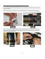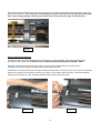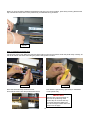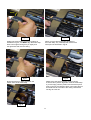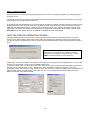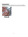
1
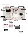
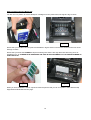
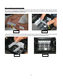
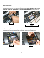
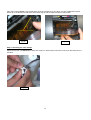
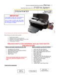
PermaJet
Assembly Instructions for:R1400
Ink System
ECO-FLO CONTINUOUS INK SYSTEM
Epson R1400
EPSON PRINTER
Part No. APJ29421
IMPORTANT
If your printer is new, set it up according to
the enclosed manufacturers instructions.
This is a check to ensure your new printer
and drivers are working correctly before the
Eco-Flo System is installed.
Epson R1400 Eco-Flo Shown
It is very important you read these instructions carefully before you begin!
We will take you through the following steps:
1
2
3
4
5
Preparing your Injector
Setting up of the Inks in the bottle tray
Installation of the modified injector to your printer
Fitting of the Tube Supports System
Producing your first print.
Only start work on the installation once you have read the
instructions fully!
What is included in your Eco-Flo R1400 Kit
What you will need to Install the Eco-Flo R1400
*
*
*
*
*
*
*
*
*
Complete Eco-Flo R1400 Kit
Sharp Blade (Stanley Knife type) & Scissors
Measuring Tape or Ruler
Marking Pen or Pencil
Paper Towels
*
*
*
*
*
*
*
*
Please read carefully before you continue and
refer to the components diagram over the
page
1
Injector Set with tubes attached
Set 6 Inks & empty 100ml bottles
6 Bottle Caps & clear piping tubes
Tube Support Bracket with Self Adhesive
Pads fitted
Bottle Holder Tray
Special Injector Lid & 2 Chip Blocks
1x Grey/White Tube Clip with adhesive pad
Installation Instructions and Profiles CD
10ml Syringe & wing adaptor
Pair of latex gloves
6 Tube Clamps
Foam Strip
Check List for Components
Set of 6 125ml
Inks
Bottle Caps &
Clear Piping
Tube Support
Bracket
10ml Syringe
Injector Set &
Tubes
Bottle Holder Tray
Special Injector
Lid
6 Empty 100ml
Bottles
Wing Adaptor
Tube Clip With
Adhesive Pad
Pair of Latex
Gloves
6 Tube
Clamps
Set of Three Chip
Support Bars
Set of 2 Chip
Blocks
Foam Strip
____________________________________________________________________________________________
2
Check Printer Condition
If you have a brand new printer, follow the Epson instructions for setting up your printer. Use the Epson cartridges
that came with the printer. Follow normal installation instructions for the software. Test the printer by printing
pictures. Learn how to use the Epson utilities to run a Nozzle pattern check and to run a Cleaning Cycle.
Make sure that the printer can produce a perfect nozzle pattern
before proceeding with Eco-Flo installation.
If you have been using the printer in the past, just make sure it produces a perfect nozzle pattern before proceeding
with the Eco-Flo installation. If the Nozzle pattern has any gaps whatsoever, then run cleaning cycles until it prints
perfectly.
DO NOT INSTALL THE ECO-FLO IF YOUR PRINTER IS NOT FULLY FUNCTIONAL
Disconnecting Power From the Printer
Push, but do not hold the INK button on the printer. This will move the injectors to the “replacement” position. After
they move to this position, which is just slightly to the left of the parked position, SWITCH OFF THE POWER AT
THE WALL SOCKET. Now the injector head can be moved from side to side by hand. We will tell you later when
to reconnect the printer power supply. Remove the original Epson injectors from the printer (Power is disconnected).
Set them aside on some paper towel. DONOT throw away, you may need them someday. Wrap in a zip-lock plastic
bag for cool dry safe keeping.
3
INSTALLATION OF YOUR ECO-FLO KIT
Step 1 Removing the Injector Lid
You will need to remove the printer lid on the injector carrier as shown illustrated from the diagrams below. Store
this somewhere safe should you ever wish to return the printer to its original setup.
The lid is held in place by two ‘Lugs’ on either side, once you have the LEFT side disconnected, the second lug can
ONLY be removed by using a sharp Stanley knife type and scoring the plastic within the head as illustrated in Fig.3.
Fig.2
Fig.1
Please note that the measurement and location of scoring would be inline with the THIRD GROOVE along as
indicated. When you have scored this several times take a fine screw driver as indicated in Fig.4 and very gently
praise the excess plastic piece off. Removing this excess piece will enable you to remove the lid by twisting this
towards you as illustrated in Fig.5.
3rd Groove
2nd Groove
Scoring point
st
1 Groove
Fig.4
Fig.3
Fig.5
4
Step 2 Moving the Printer Head
You are now able to move the printer head manually to the centre area of the printer. See below.
Fig.6
Step 3 Bottle Preparation
Locate the coloured bottle caps and straight lengths of plastic tubes. Insert the straight tube firmly into the bottom of
each bottle cap see Fig.7 below.
Step 4 Tube Preparation
Fig.7
5
Step 4 Tube Preparation
Using a pair of scissors snip gently at the end of each tube. Please see Fig.8 below.
Fig.8
Strip back all the tubes by approx 150mm. Please note when assembling the tubes to the bottle caps you may need
to strip back more of the tubing in order for the bottles to be seated correctly within the bottle tray.
Fig.9
Fig.10 showing
tubes stripped back
6
Step 5 Preparation of The Clamps & Inks
You are now ready to attach the tube clamps to the tubes as indicated in Fig.11 below.
Now please fill all the bottles with the correct inks; please ensure that all ink has been filled correctly as indicated by
the bottle caps that are colour coded, see Fig.12 below.
Fig.11
Fig.12
Step 6 Positioning the Ink Bottles in The Tray
You are now ready to position the ink bottles in the bottle holder tray as indicated below on the LEFT hand side on
the same level as the printer.
LC
C
BK
M
Y
LM
R1400 Setup
7
Step 7 Assembling the Tubing to the Bottle Caps
When you have completed the above process insert the correct tubes to the correct ink bottles. PLEASE TAKE
CARE when doing this as if this is connected incorrectly there is no turning back see Fig.13 & Fig.14
Fig.13
Fig.14
Step 8 Priming the Ink Through the Injectors
You are now ready to start the ink priming process starting with the YELLOW. This process is carried out by
inserting the 10ml syringe and wing adaptor at the base of the injector.
Fig.15
Wing Adaptor
Shown
8
PLEASE ENSURE THAT THE WING ADAPTOR (TIP ONLY) IS GENTLY, BUT MAKES A FIRM SEAL ON THE
BASE OF THE INJECTOR, DO NOT push the tip into the injector as this shall split the base of the injector
see Fig.16.
PLEASE ENSURE that you DOUBLE CHECK that the correct tube is located to the correct ink bottle before
pulling back on the syringe (see Fig.17), you may need assistance by another person for the next stage.
Priming an Injector
Fig.17
Fig.16
At this point LOCK the tube with the white clamp (see Fig.18) before removing the syringe from the bottom base of
the injector to avoid any air traveling in the injector.
Any ink remaining in the syringe can be put back into the correct ink bottle. MAKE SURE you wash the syringe with
warm water ready for the next colour to be primed. Repeat this process for all the inks so that you finish up with a
set of injectors and tubes full of ink as illustrated in Fig.19.
Ink tube being
clamped
Fig.18
Fig.19
9
Step 9 Installing the Chip Block Unit
You are now in a position to remove the Epson cartridges from the printer head, see Fig.20 & Fig.21 below.
Fig. 20
Fig. 21
Ensure that you hold the Colour chip block as indicated in Fig.22 and do not touch the contacts as this can cause
damage or failure.
Ensure that you locate the CORRECT chip block making sure that the two legs either side are facing down as
indicated in Fig. 22. PLEASE NOTE INSERTING THE CHIP BLOCK INCORRECTLY CAN CAUSE DAMAGE TO
THE CONTACTS.
Fig. 22
Fig. 23
When you have installed the Colour chip block within the printer head you can now position and install the Chip
Support Bar as illustrated over the page.
10
Step 10 Installing the Chip Support Bars
When you have positioned the chip blocks into place you will need to insert and install the support bars as indicated
the correct way up (Arrow up) as illustrated in Fig. 24. Please ensure that you insert the bars as illustrated in Fig.25
making sure that the Groove is on the far end.
Groove
Fig. 24
Fig. 25
Insert the bar as illustrated making sure that this is pushed firmly into place see Fig.26, repeat this for the other side
and the other chip block, so that you have both chip blocks and support bars as illustrated if Fig.27.
Fig. 26
Fig. 27
11
Step 11 Install Injectors
Please place the set of 6 injectors in the printer carriage that is now parked in the centre of the printer.
Carefully align them, and when you are happy the injectors are in position. PLEASE BE CAREFUL NOT TO PUSH
TOO HARD, AS THIS WILL CAUSE DAMAGE TO THE INJECTOR & PRINTER HEAD. Push the injectors home
until you feel a positive seated position, see Fig.28 below. When all are in, they should look like Fig.29 below.
Fig.28
Fig.29
Picture shows injectors fully installed in a
R1400
Step 12 Fixing the Special Printer Lid
Attach the special printer lid that has been supplied making sure that none of the tubing catches or squashes
between the lid and housing, as this will stop any ink flowing into the printer heads. At this stage you MUST align the
tubes in the correct manner as illustrated in Fig.30. Align & position the special lid as indicated in Fig.31.
Fig.31
Fig.30
12
Align and locate the SLOT in the R1400 printer head as indicated in Fig.32. When you have installed the special
printer lid on the R1400 it should finish and look like Fig.33 with the tubes moulded in that position.
Slot within the printer head
Fig.32
Fig.33
Step 13 Unlocking the Tube Clamps
Please ensure that you UNLOCK the white tube clamps on all the tubes so that ink can flow into the heads when in
operation.
Fig.34
13
Step 14 Installing the Central Tube Support Bracket & Aligning the Tubes
The Tube Support Bracket has Self Adhesive Strips on it. Use an alcohol or cleaning solution and clean the top of
the printer housing where the Tube Support Bracket is going to be attached, see Fig.36. Then make sure the area is
dry before proceeding.
Remove the adhesive backing off both ends. Carefully install and align the Tube Support Bracket in its proper
rd
location 47mm from the right edge of the recess, as shown in Fig.36 or the 3 square from the right as illustrated.
rd
3
nd
2
st
1
47mm
Fig.35
Fig.36
When you have aligned and fixed the Tube Support Bracket in its position as illustrated in Fig.37 below. Please
ensure that the Central Tube Support Bracket, the top and bottom are firmly stuck down to the printer body. The
tubes can now be inserted through the available opening in the middle of the bracket by squeezing the
tubes as indicated in Fig.38 below.
Fig.37
Fig.38
14
Please ensure that the tubing has just enough slack which may need to be adjusted to allow movement of the print
head without restriction. This can be done manually by moving the head to the left and right and checking that
there is just enough tubing to allow the print head to move freely from left to right, see Fig.39 below.
Fig.39
Step 15 Install Final Tube Clip
The last tube clip goes on the left edge of the printer housing see Fig.40 below. Clean this area with alcohol
and wipe dry with a paper towel. DO NOT FULLY OPEN THE TUBE CLIP BACK AS THIS WILL SNAP!
Place the Tube Clip onto the printer body, making sure it is in the correct position to hold the tubes in
a straight line along the length of the printer to the Tube Support Bracket.
All the tubes must lay flat so they do not interfere with print head motion, see Fig.41 below. You must ensure that the
tubes do not come into contact with the printer body. When you are happy with the location, remove the adhesive
backing from the back of the clip. Carefully install and align the tube clip in its location.
Fig.40
Fig.41
15
When you have carefully installed and aligned the tube clip in its correct location, press firmly ensuring that the tube
clip is clicked and stuck down to the printer body, as illustrated in Fig.42 below.
Fig.42
Step 16 Installing the Foam Strip
The purpose of the Foam Strip is to ensure that the tubing on the Eco-Flo travels under the printer body correctly, as
well as to cushion the tubes from hitting the printer casing when in motion.
Fig.43
Fig.44
Move the head manually across to the left
and bend back the Foam Strip as illustrated above.
Peel back the yellow sticky tape ready for installation
on the printer body.
IMPORTANT!
Please note from the diagram on
the left, the positioning of the
Foam Strip is crucial in that only
one tube should be visible from
the above angle. Please follow the
steps over the page.
16
43mm
Fig.45
Position the Foam Strip in its correct location as
indicated in Fig.45, You MUST align the Foam Strip
flush to the edge ensuring that you lightly tack
the right hand side onto the casing.
Fig.46
When you have placed the right hand side of
the Foam Strip, very carefully bend it back to the
white point as illustrated in Fig.46.
Fig.47
Fig.48
Now ensure that you lightly tack down the
bottom halve of the Foam Strip.
Please move the head manually across ensuring
that it travels in perfect alignment under the Foam Strip.
If you are happy with the position and movement press
firmly on the top and bottom halves of the Foam Strip so
that it adheres to each side of the casing. Please also
see Fig.49 to the left.
Fig.49
17
Step 17 Testing the System
Push the injectors to the far right and plug the printer back on. Have your graphics program (e.g. Photoshop) open
and ready to use.
The printer should come on and the head should move back and forth a few times and do a cleaning cycle. When it
stops moving, only the green light should be on.
A red light at this point indicates that one of the chips has not been recognized or seated correctly. If this is the case
please push firmly on the Chip block that is not registering. If this does not solve the issue then please LOCK all
tubes with the white clamps and very carefully remove the Injectors. Now very carefully check the chip that is not
registering. It is advisable to clean the chip by wiping the contacts with a soft cloth and re-install the system again.
Remember when the system has been re-installed to UNLOCK the white tube clamps.
HOW THE SPECIAL PERMACHIP WORKS: The PermaChips operate as a normal chip on a injector and while printing the ink levels will drop as a normal
injector on the status monitor. When the ink levels reach low indicated by a flashing red light on the printer panel,
you will need to turn the printer OFF, wait for 30 seconds and restart the printer. This process will reset the chips to
FULL.
A window will open when you make your first print.
This informs you that these are not Epson injectors
and gives you the option to continue or quit – choose
YES and continue printing in the normal way.
At this stage, your Eco-Flo system is in a position to be used as your injectors are now filled with ink. You may need
to carry out a head clean in order to get a complete nozzle check.
To execute a head clean you will need to open a document in any program and select the print option from the tool
bar (this can normally be found in ‘File’). Ensuring you have selected the correct printer driver, click on the
‘Properties’ button. This will open a new window in which you will need to select the ‘Utilities’ tab. In this window you
will find all the options for head cleaning and nozzle checks. For more detailed instructions please refer to the
Epson manual that came with the printer.
18
Step 18 Removing the Injectors
Please note before removing the injectors you MUST clamp the tubing on the relevant injectors by LOCKING the
White tube clamps to avoid air traveling up the injector and into the tube. At this point press the ink change button on
the front panel of the printer so that you are ready to change or remove the injectors, this function will bring the head
unit to the left.
Locking the tube
clamps
19
ON THE COMPACT DISC :THERE IS A CD SUPPLIED WITH YOUR KIT. ON THE CD ARE COPIES OF THE
FOLLOWING :1
2
3
4
5
ECO-FLO INSTALLATION INSTRUCTIONS FOR ALL TYPES OF
PRINTERS AND SYSTEMS
TROUBLE SHOOTING GUIDE
INK PURGE TEST FILES AND TONE CHARTS
ICC PROFILES FOR USE WITH PERMAJET COLOUR INK AND PAPER
COMBINATIONS
CURVES FOR USE WITH MONOCHROMEPRO INK SYSTEM.
IN ORDER TO USE THE PERMAJET INK SYSTEM TO ITS FULL
POTENTIAL, YOU SHOULD NOW TAKE THE TIME TO OPEN
THE ENCLOSED CD AND PROCEED TO READ THE FULL
SECTION ON PROFILES AND THE
“HOW TO INSTALL AND USE ICC PROFILES” DOCUMENT.
FULL DATA IS INCLUDED IN THIS FILE TO EXPLAIN HOW TO
GET THE FULL BENEFITS OF COLOUR MANAGEMENT AND
BEST RESULTS WITH YOUR IMAGES.
20
FAQ»S & Caring For Your Eco-Flo √ READ CAREFULLY!!!
Here are some tips to make sure that your new system performs trouble-free.
•
It is advised to gently shake by rotation each ink bottle on a regular weekly basis. This is to ensure the
XL (Xtra Life) Dye inks stay suspended in solution and gives constant results.
•
After printing, ink in the tubes should be close to the injectors. The next morning, the ink may have
retracted a little this is absolutely normal.
When you start to print again the ink will be drawn into the injectors and it will function normally. The
system is designed to have some air at the top of the injector to prevent siphoning and spitting. This air
will expand and contract with temperature and pressure changes. This is a characteristic of the
system.
However, if you see that any of the inks have retracted all the way back to the bottles, this may be a
technical problem. Contact our technical line immediately before acting.
•
It is advisable not to let your printer sit for long periods of time without printing something. The use of
a timer to power up the printer should you be going away for a long period of time is recommended.
Timers can be purchased from all good hardware stores. This approach will not require the computer
being switched on and off manually. Simply plug the printer»s plug in to the timer and plug the time into
the wall socket or extension lead and set to come on once a week. This process will run a cleaning
cycle and maintain your system.
•
Keep the whole unit out of direct sunlight and sources of direct heat.
•
Routine Maintenance: - Assuming that you have followed all routine maintenance guidance provided by
the printer manufacturer (this includes print head alignment, lubrication & cleaning of moving parts and
nozzle cleaning procedures), there may be times when you need to additionally carry out Eco-Flo
maintenance. Therefore, always keep all the items that came with your kit in their original box in a safe
place and retain this instruction manual with them. A charge is applicable for occasions where we have
to send you maintenance items which you have mislaid.
IMPORTANT
DO NOT remove the injectors from the printer unless specifically
instructed by an authorised Permajet technician to do so. Removing
the injectors once installed may cause system damage and
invalidate further technical support.
DO NOT lift the inks above the Printer. This would cause the ink to flood
inside - keep the bottles at the same level as the printer by putting them
on the same table.
www.permajet.com
21