1
NOTEBOOK PC
USER’S MANUAL
Product Name:
Notebook PC
Manual Revision: 1.02 E751
Release Date:
May 2001
Safety Statements
Federal Communications Commission Statement
This device complies with FCC Rules Part 15. Operation is subject to the following two conditions:
• This device may not cause harmful interference, and
• This device must accept any interference received, including interference that may cause undesired
operation.
This equipment has been tested and found to comply with the limits for a class B digital device, pursuant
to Part 15 of the Federal Communications Commission (FCC) rules. These limits are designed to provide
reasonable protection against harmful interference in a residential installation. This equipment generates,
uses, and can radiate radio frequency energy and, if not installed and used in accordance with the instructions, may cause harmful interference to radio communications. However, there is no guarantee that
interference will not occur in a particular installation. If this equipment does cause harmful interference
to radio or television reception, which can be determined by turning the equipment off and on, the user is
encouraged to try to correct the interference by one or more of the following measures:
•
•
•
•
Reorient or relocate the receiving antenna.
Increase the separation between the equipment and receiver.
Connect the equipment into an outlet on a circuit different from that to which the receiver is connected.
Consult the dealer or an experienced radio/TV technician for help.
WARNING! The use of a shielded-type power cord is required in order to meet FCC
emission limits and to prevent interference to the nearby radio and television reception. It is essential that only the supplied power cord be used. Use only shielded
cables to connect I/O devices to this equipment. You are cautioned that changes or
modifications not expressly approved by the party responsible for compliance could
void your authority to operate the equipment.
Reprinted from the Code of Federal Regulations #47, part 15.193, 1993. Washington DC: Office of the
Federal Register, National Archives and Records Administration, U.S. Government Printing Office.
Canadian Department of Communications Statement
This digital apparatus does not exceed the Class B limits for radio noise emissions from digital apparatus
set out in the Radio Interference Regulations of the Canadian Department of Communications.
This Class B digital apparatus complies with Canadian ICES-003.
Cet appareil numérique de la classe B est conforme à la norme NMB-003 du Canada.
For use with AC Adaptor Model ADP-45GB (Pour Utiliser Avec Modele ADP-45GB)
2
Safety Statements
Nordic Cautions (for Notebook PC with Lithium-Ion Battery)
CAUTION! Danger of explosion if battery is incorrectly replaced. Replace only with the same or
equivalent type recommended by the manufacturer. Dispose of used batteries according to the
manufacturer’s instructions. (English)
VORSICHT! Explosionsgetahr bei unsachgemäßen Austausch der Batterie. Ersatz nur durch denselben
oder einem vom Hersteller empfohlenem ähnlichen Typ. Entsorgung gebrauchter Batterien nach Angaben
des Herstellers. (German)
ADVARSELI! Lithiumbatteri - Eksplosionsfare ved fejlagtig håndtering. Udskiftning må kun ske med
batteri af samme fabrikat og type. Levér det brugte batteri tilbage til leverandøren. (Danish)
VARNING! Explosionsfara vid felaktigt batteribyte. Använd samma batterityp eller en ekvivalent typ
som rekommenderas av apparattillverkaren. Kassera använt batteri enligt fabrikantens instruktion. (Swedish)
VAROITUS! Paristo voi räjähtää, jos se on virheellisesti asennettu. Vaihda paristo ainoastaan laitevalmistajan
sousittelemaan tyyppiin. Hävitä käytetty paristo valmistagan ohjeiden mukaisesti. (Finnish)
ATTENTION! Il y a danger d’explosion s’il y a remplacement incorrect de la batterie. Remplacer
uniquement avec une batterie du mêre type ou d’un type équivalent recommandé par le constructeur.
Mettre au rebut les batteries usagées conformément aux instructions du fabricant. (French)
ADVARSEL! Eksplosjonsfare ved feilaktig skifte av batteri. Benytt samme batteritype eller en
tilsvarende type anbefalt av apparatfabrikanten. Brukte batterier kasseres i henhold til fabrikantens
instruksjoner. (Norwegian)
(Japanese)
Macrovision Corporation Product Notice
This product incorporates copyright protection technology that is protected by method claims of certain
U.S.A. patents and other intellectual property rights owned by Macrovision Corporation and other rights
owners. Use of this copyright protection technology must be authorized by Macrovision Corporation, and
is intended for home and other limited viewing uses only unless otherwise authorized by Macrovision
Corporation. Reverse engineering or disassembly is prohibited.
3
Safety Statements
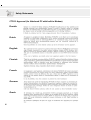
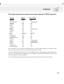
CTR 21 Approval (for Notebook PC with built-in Modem)
Danish
Dutch
English
Finnish
French
German
Greek
4
Safety Statements
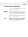
CTR 21 Approval (for Notebook PC with built-in Modem)
Italian
Portuguese
Spanish
Swedish
5
Safety Statements
UL Safety Notices
Required for UL 1459 covering telecommunications (telephone) equipment intended to be electrically
connected to a telecommunication network that has an operating voltage to ground that does not exceed
200V peak, 300V peak-to-peak, and 105V rms, and installed or used in accordance with the National
Electrical Code (NFPA 70).
When using the Notebook PC modem, basic safety precautions should always be followed to reduce
the risk of fire, electric shock, and injury to persons, including the following:
• Do not use the Notebook PC near water, for example, near a bath tub, wash bowl, kitchen sink or
laundry tub, in a wet basement or near a swimming pool.
• Do not use the Notebook PC during an electrical storm. There may be a remote risk of electric shock
from lightning.
• Do not use the Notebook PC in the vicinity of a gas leak.
Required for UL 1642 covering primary (nonrechargeable) and secondary (rechargeable) lithium batteries for use as power sources in products. These batteries contain metallic lithium, or a lithium alloy,
or a lithium ion, and may consist of a single electrochemical cell or two or more cells connected in
series, parallel, or both, that convert chemical energy into electrical energy by an irreversible or reversible chemical reaction.
• Do not dispose the Notebook PC battery pack in a fire, as they may explode. Check with local codes for
possible special disposal instructions to reduce the risk of injury to persons due to fire or explosion.
• Do not use power adapters or batteries from other devices to reduce the risk of injury to persons due
to fire or explosion. Use only UL certified power adapters or batteries supplied by the manufacturer
or authorized retailers.
6
Table of Contents
1. INTRODUCING THE NOTEBOOK PC
11
About This User’s Manual ...................................................................................... 12
Notes For This Manual...................................................................................... 12
Caring Information ................................................................................................. 13
Transportation Precautions .................................................................................... 14
2. KNOWING THE PARTS
15
Top Side ................................................................................................................. 16
Front Side .............................................................................................................. 18
Left Side ................................................................................................................. 19
Right Side .............................................................................................................. 20
Rear Side ............................................................................................................... 22
3. GETTING STARTED
25
Installing and Removing the Battery Pack ............................................................. 26
Using the Battery Pack .......................................................................................... 27
Before using your Notebook PC on the road .................................................... 27
Battery Care ...................................................................................................... 27
Operating Systems ................................................................................................ 27
Support Software .............................................................................................. 27
Power Connection ................................................................................................. 28
Powering ON The Notebook PC ............................................................................ 29
The Power-On Self Test (POST) ...................................................................... 29
Save-to-Disk Partition ............................................................................................ 30
Restarting or Rebooting ......................................................................................... 30
Powering OFF the Notebook PC ........................................................................... 30
Status Indicators and Instant Launch Keys ........................................................... 31
CD Control Buttons and Indicator .......................................................................... 32
Using the Keyboard ............................................................................................... 33
Colored Hot Keys .............................................................................................. 33
Microsoft Windows™ Keys ............................................................................... 34
Keyboard as a Numeric Keypad ....................................................................... 34
Keyboard as Cursors ........................................................................................ 35
4. USING THE NOTEBOOK PC
37
Pointing Device ...................................................................................................... 38
Using the Touchpad .......................................................................................... 38
Caring for the Touchpad ................................................................................... 41
Mouse or Keyboard Connection (Optional) ........................................................... 41
CD/DVD-ROM Drive .............................................................................................. 42
Laser Safety ...................................................................................................... 43
CDRH Regulations ........................................................................................... 43
Using the CD-ROM Drive ................................................................................. 43
DVD-ROM Drive Information ............................................................................ 44
7
Table of Contents
Regional Playback Information ......................................................................... 45
Region Definitions ............................................................................................. 45
Listening to Audio CD ....................................................................................... 46
Optional External Connections .............................................................................. 47
PC Card (PCMCIA) Sockets .................................................................................. 48
32-bit CardBus Support .................................................................................... 48
Removing a PC Card (PCMCIA) ...................................................................... 49
Inserting a PC Card (PCMCIA) ......................................................................... 49
Modem and Network Connections ......................................................................... 50
Modem Connection ........................................................................................... 50
Network Connection ......................................................................................... 51
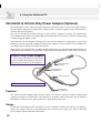
IR Wireless Communication .................................................................................. 52
Guidelines for using IR communication ............................................................ 52
Enabling Infrared .............................................................................................. 52
AC Power System .................................................................................................. 53
Battery Power System ........................................................................................... 53
Charging the Battery Pack ................................................................................ 53
Using Battery Power ......................................................................................... 54
Power Management Modes ................................................................................... 55
Full Power Mode & Maximum Performance ..................................................... 55
APM and ACPI .................................................................................................. 55
Suspend Mode .................................................................................................. 55
Standby Mode ................................................................................................... 56
Power State Summary ...................................................................................... 56
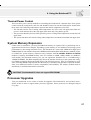
Thermal Power Control ..................................................................................... 57
System Memory Expansion ................................................................................... 57
Processor Upgrades .............................................................................................. 57
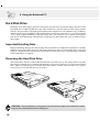
Hard Disk Drive ...................................................................................................... 58
Important Handling Note ................................................................................... 58
Removing the Hard Disk Drive ......................................................................... 58
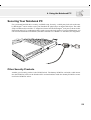
Securing Your Notebook PC .................................................................................. 59
Other Security Products .................................................................................... 59
Vehicle/Air Power Adapter (Optional) .................................................................... 60
Features ............................................................................................................ 60
Usage ............................................................................................................... 60
8
Table of Contents
5. CONFIGURING THE BIOS
61
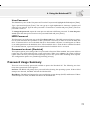
Managing and Updating Your BIOS ....................................................................... 62
Managing and Updating Your BIOS From Your Hard Disk Drive ...................... 62
Updating BIOS Procedures (from floppy disk) .................................................. 63
BIOS Setup Program ............................................................................................. 64
BIOS Menu Bar ................................................................................................. 65
BIOS Legend Bar .............................................................................................. 65
Main Menu ............................................................................................................. 67
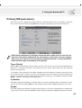
Primary IDE (sub-menu) ........................................................................................ 69
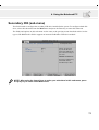
Secondary IDE (sub-menu) ................................................................................... 71
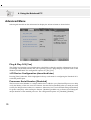
Advanced Menu ..................................................................................................... 72
I/O Device Configuration (sub-menu) .................................................................... 74
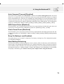
Security Menu ........................................................................................................ 76
Password Usage Summary ................................................................................... 77
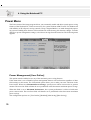
Power Menu ........................................................................................................... 78
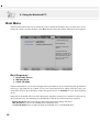
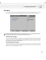
Boot Menu ............................................................................................................. 82
Exit Menu ............................................................................................................... 83
APPENDIX
85
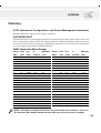
Internal Modem Compliancy .................................................................................. 86
Protocols and Compliancy ................................................................................ 86
Glossary ................................................................................................................. 89
Index ...................................................................................................................... 93
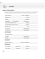
Owner Information ................................................................................................. 96
9
10
1. INTRODUCING THE NOTEBOOK PC
About This User’s Manual
Caring Information
Transportation Precautions
11
1. Introducing the Notebook PC
About This User’s Manual
You are reading the Notebook PC User’s Manual. This User’s Manual provides information on the
various components in the Notebook PC and how to use them. The following are major sections of this
User’s Manuals:
1. Introducing the Notebook PC
Introduces you to the Notebook PC and this User’s Manual.
2. Knowing the Parts
Gives you information on the Notebook PC’s components.
3. Getting Started
Gives you information on getting started with the Notebook PC.
4. Using the Notebook PC
Gives you information on using the Notebook PC’s components.
5. Configuring the BIOS
Gives you information on configuring the BIOS software.
6. Appendix
Introduces you to optional accessories and gives additional information.
Notes For This Manual
This User’s Manual was created using Macintosh versions of Adobe® PageMaker™ 6.52, Adobe®
Photoshop™ 5.5, Adobe® Illustrator® 8.0, and Macromedia® Freehand™ 8.0.1. The body text type used
in this manual is “Times” (MAC) or “Times New Roman” (Windows™) and headings are “Helvetica”
(MAC) or “Arial” (Windows™). A few notes and warnings in bold are used throughout this guide that
you should be aware of in order to complete certain tasks safely and completely. These notes have
different degrees of importance as described below:
WARNING! Information to prevent
damage to components, damage to
data, or personal injury.
TIP: Tips and useful information for
power (advanced) computer users.
CAUTION! Information on actions that
must be avoided to prevent damage to
components, damage to data, or personal injury.
NOTE: Tips and information to aid in
completing a task.
Text enclosed in < > or [ ] represents a key on the keyboard; do not actually type the <
> or [ ] and the enclosed letters.
12
1. Introducing the Notebook PC
Caring Information
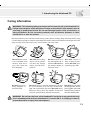
WARNING! The following safety precautions will increase the life of the Notebook PC.
Follow all precautions and instructions. Except as described in this manual, refer all
servicing to qualified personnel. Do not use damaged power cords, accessories, or
other peripherals. Do not use strong solvents such as thinners, benzene, or other
chemicals on or near the surface.
Disconnect the AC power and remove the battery pack(s) before cleaning. Wipe the Notebook PC using
a clean cellulose sponge or chamois cloth dampened with a solution of nonabrasive detergent and a few
drops of warm water and remove any extra moisture with a dry cloth.
DO NOT place on uneven or unstable work
surfaces. Seek servicing if the casing has
been damaged.
DO NOT place or drop
objects on top and do
not shove any foreign
objects into the Notebook PC.
DO NOT expose to
strong magnetic or
electrical fields.
DO NOT expose to extreme temperatures (below
0˚C (32˚F) or above 50˚C (122˚F)) or to direct sunlight. Do not block the fan vents! DO NOT throw
batteries in fires as they may explode. Check local
codes for special battery disposal instructions.
DO NOT expose to or
use near liquids, rain, or
moisture. DO NOT use
the modem during an
electrical storm.
DO NOT expose to
dirty or dusty environments. DO NOT operate during a gas leak.
DO NOT press or touch
the display panel. Do not
place together with small
items that may scratch or
enter the Notebook PC.
WARNING! Do not leave the base of the Notebook PC on the lap or any part of the body
for an extended period while the Notebook PC is turned ON or is charging in order to
prevent discomfort or injury from heat exposure.
13
1. Introducing the Notebook PC
Transportation Precautions
To prepare the Notebook PC for transport, you should turn it OFF and disconnect all external peripherals to prevent damage to the connectors. The hard disk drive’s head retracts when the power is
turned OFF to prevent scratching of the hard disk surface during transport. Therefore, you should not
transport the Notebook PC while the power is still ON. Close the display panel and check that it is
latched securely in the closed position to protect the keyboard and display panel.
Remove Floppy Disks
Make sure that the 1.44MB floppy disk drive does not contain a diskette when transporting internal or
external floppy disk drives. When a diskette is inserted into the floppy disk drive, the eject button
protrudes out. If you attempt to transport the floppy disk drive with a diskette in the drive, you risk
damaging the eject button and also risk scratching the surface of the diskette when the floppy disk drive
is jolted.
Cover Your Notebook PC
Use a carrying case such as the one supplied with your Notebook PC to protect it from dirt, water,
shock, and scratches.
NOTE: The surface glaze is easily dulled if not properly cared for. Be careful not to rub
or scrap the Notebook PC surfaces when transporting your Notebook PC.
Charge Your Batteries
If you intend to use battery power, be sure to fully charge your battery pack and any optional battery
packs before going on long trips. Remember that the power adapter charges the battery pack as long as
it is plugged into the computer and an AC power source. Be aware that it takes much longer to charge
the battery pack when the Notebook PC is in use.
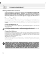
Airplane Precautions
Contact your airline if you want to use the Notebook PC on the airplane. Most airlines will have restrictions for using electronic devices. Most airlines will allow electronic use only between and not during
takeoffs and landings.
CAUTION! There are three main types of airport security devices: X-ray machines
(used on items placed on conveyor belts), magnetic detectors (used on people walking through security checks), and magnetic wands (hand-held devices used on people
or individual items). You can send your Notebook PC and diskettes through airport Xray machines. However, it is recommended that you do not send your Notebook PC or
diskettes through airport magnetic detectors or expose them to magnetic wands.
14
2. KNOWING THE PARTS
Top Side
Front Side
Left Side
Right Side
Rear Side
15
2. Knowing the Parts
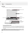
Top Side
Refer to the diagram below to identify the components on the top side of the Notebook PC.
Display Panel Latch
Display Panel
Microphone
Status LEDs
Instant Launch Keys
Keyboard
Touchpad
Touchpad Buttons
Scroll Buttons
CD
Opening the Display Panel
One spring-loaded latch on the front of the Notebook PC locks the display panel in the closed position
when the Notebook PC is not in use. To open the display panel, slide the latch to the left with your
thumb and lift up on the display panel at the same time. This design allows a single hand to be used
when opening the display panel. Slowly tilt the display panel forward or backward to a comfortable
viewing angle.
WARNING! When opening, do not force the display panel down to the table or else the
hinges may break! Never lift the Notebook PC by the display panel!
16
2. Knowing the Parts
The following describes the components of the Notebook PC as viewed from the top as shown by the
illustration on the previous page.
Display Panel
The display panel functions the same as a desktop monitor. The Notebook PC uses an active matrix
TFT LCD, which provides excellent viewing like that of desktop monitors. Unlike desktop monitors,
the LCD panel does not produce any radiation or flickering, so it is easier on the eyes.
NOTE: By default, closing the display panel turns OFF the display to conserve power.
Opening the display panel turns the display back ON. You can change the display
panel settings in the Advanced Power Management in Windows.
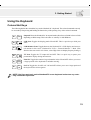
Display Panel Care
The LCD screen is very delicate and requires careful handling. Pay attention to the following precautions:
•
•
•
•
•
When not in use, keep the display panel closed to prevent dust accumulation.
Do not use chemical cleaners on the screen. Wipe only with a dry cloth or tissue.
Do not put your fingers or any objects directly on the screen.
Do not press or lay any objects on the machine when it is closed.
Do not carry the Notebook PC with small or sharp objects (e.g. paper clips or staples) that may enter
the Notebook PC and scratch the display panel.
Microphone
The built-in microphone provides a source for general note taking, voicemail recording, or for use with
Internet phone software. See “Left Side” for external microphone connection.
Status LEDs (top)
The Notebook PC has status LEDs above the keyboard to display storage device access, number lock,
and capital lock statuses. Details are described later in this manual.
Instant Launch Keys
Three keys above the keyboard provide instant access to predefined applications that may also be
redefined by the user. The instant launch keys allows launching of corresponding applications even
while the Notebook PC is turned OFF.
Keyboard
The keyboard provides full-sized keys with comfortable travel (depth at which the keys can be depressed) and palm rest for both hands. Two Windows™ function keys are provided to help ease navigation in the Windows™ operating system.
Touchpad and Buttons
The touchpad with its four buttons is a pointing device that provides the same functions as a desktop
mouse with scrolling capability. Scrolling allows you to move up or down in a document or web page
without having to click on the scroll bars.
17
2. Knowing the Parts
Front Side
Refer to the diagram below to identify the components on the front side of the Notebook PC.
308mm
41mm
Display Panel Latch
CD
Left
Speaker
Power &
Charge
Indicators
CD Control Buttons
Email/CD
Indicator
Right
Speaker
Display Panel Latch
One display panel latch is used to lock the display panel in the closed position. To open the display
panel, slide the latch to the left with your thumb and lift up on the display panel at the same time.
Power Indicator
The green LED lights to indicate that the Notebook PC is turned ON and blink when the Notebook PC
is in the Suspend-to-RAM (standby) mode. This LED is OFF when the Notebook PC is in the Suspendto-Disk (hibernation) mode.
Charge Indicator
Indicates that the battery is being charged when ON and fully charged when OFF. This LED only lights
when the power adapter is used. This LED does not light up if there is no installed battery. Slow flash
means the battery power is low and requires charging. Quick flashing means that the battery pack
cannot be charged and needs a replacement.
CD Control Buttons & CD Indicator
(described in section 3)
Email Indicator
Flashes when there is one or more new email(s) in your email program’s inbox. This function requires
software setup and may not be currently configured on your Notebook PC. This function is designed for
Microsoft email software only and may not work with email software from other companies.
Speaker
The built-in stereo speakers allow you to separately hear left and right channel audio without additional
attachments. The multimedia sound system features an integrated digital audio controller that produces
rich, vibrant sound in high quality 16-bit stereo. All audio features are software controlled.
18
2. Knowing the Parts
Left Side
Refer to the diagram below to identify the components on the left side of the Notebook PC.
41mm
250mm
Head-Out
Mic-In
Fast Infrared Port
Air Vent
Audio-In
Fast Infrared Power
Port
Switch
PC Card (PCMCIA)
Sockets & Eject
The fast infrared (IrDA) communication port allows convenient wireless data communication with
infrared-equipped devices or computers up to 4Mbits/sec. This allows easy wireless synchronization
with PDAs or mobile phones and even wireless printing to printers. If your office supports IrDA networking, you can have wireless connection to a network anywhere provided there is a direct line of
sight to an IrDA node. Small offices can use IrDA technology to share a printer between several closely
placed Notebook PCs and even send files to each other without a network.
Power Switch
The power switch allows powering ON and OFF the Notebook PC. Slide the switch once to turn ON
and once to turn OFF the Notebook PC. To prevent accidental turning OFF of the power, it is designed
to take longer (about 4 seconds) to turn OFF than to turn ON the power.
Air Vent
The air vents allow fresh air to be used to circulate warm air out of the Notebook PC. Be careful not to
block the air vents!
Audio-In Jack
The audio in provides stereo input from audio sources.
Microphone Jack
The mono microphone jack can be used to connect an external microphone or output signals from
audio devices. Using this jack automatically disables the built-in microphone.
Headphone Jack
The stereo headphone jack is used to connect the Notebook PC’s audio out signal to amplified speakers
or headphones. Using this jack automatically disables the built-in speakers.
PC Card (PCMCIA) Sockets and Eject
Two PCMCIA 2.1 compliant sockets for two Type I or Type II or one Type III PC card are available. Both
sockets support 32-bit CardBus. This allows accommodation of all Notebook PC expansion options such
as memory cards, ISDN, SCSI adapters, and wireless network adapters. The two eject buttons allow easy
ejection of individual PC cards.
19
2. Knowing the Parts
Right Side
Refer to the diagram below to identify the components on the right side of the Notebook PC.
250mm
Floppy Eject
41mm
Floppy Disk Drive
L
CD/DVD- CD/DVD
ROM Drive
Eject
CD/DVD
Emergency
Eject
PS/2 Port
Hard Disk
Drive (in tray)
Kensington®
Lock Port
The following describes the components on the right side of the Notebook PC as shown by the illustration above.
Floppy Disk Drive and Floppy Eject
This is a standard 1.44MB floppy disk drive with Japanese 3-mode floppy support. Floppy disk activity
should be seen through the activity LED above the keyboard. Unlike desktop PC floppy disk drives, the
eject button of the Notebook PC is on top of the opening to allow easy floppy ejection from the top.
WARNING! The floppy disk drive’s eject button protrudes out of the Notebook PC
when a floppy disk is fully inserted and can be easily damaged if struck. Eject the
floppy disk before transporting the Notebook PC.
CD/DVD-ROM Drive
The Notebook PC comes in a CD-ROM model or a DVD-ROM model (the DVD-ROM is also capable
of reading CDs).
CD/DVD-ROM Eject and Emergency Eject
The CD/DVD-ROM eject is an electronic eject button for opening the tray. You can also eject the CD/
DVD through the software CD/DVD player or by right clicking the CD/DVD drive in Windows™ “My
Computer.” The emergency eject is used to eject a CD/DVD in case the electronic eject does not work.
Do not use this in place of the electronic eject.
PS/2 Port
The PS/2 port is for connecting an external PS/2 mouse or PS/2 keyboard to the Notebook PC if you do
not want to use the built-in pointing device and keyboard. Simultaneous use of two PS/2 devices requires an optional PS/2 Y-adapter. It is recommended that you use either a USB mouse or a USB
keyboard so that dual PS/2 connections are not required.
20
2. Knowing the Parts
Hard Disk Drive
The hard disk drive is mounted in a removable tray. This tray is secured by a large black screw at the
bottom of the Notebook PC. The removable tray allows easy hard disk drive swapping or upgrade.
K
Kensington® Lock Port
The Kensington® lock port allows the Notebook PC to be secured using Kensington® compatible Notebook PC security products. These security products usually include a metal cable and lock that prevent
the Notebook PC to be removed from a fixed object. Some security products may also include a motion
detector to sound an alarm when moved.
21
2. Knowing the Parts
Rear Side
Refer to the diagram below to identify the components on the rear side of the Notebook PC.
41mm
308mm
DC IN
TV
Serial Port
Parallel Port
External TV Out Modem Air
LAN 2 USB DC Power
Monitor
Port
Port Vent & Port
Ports Input Jack
Port
(RJ-11) Fan (RJ-45)
The following describes the components on the rear side of the Notebook PC as shown by the illustration above.
Serial Port
The 9-pin D-sub serial port supports serial devices such as a drawing tablet, serial mouse, PDA cradle,
cellular phone link.
Parallel Port
The 25-pin D-sub parallel/printer port supports parallel devices such as a printer or a removable drive.
External Monitor Port
The 15-pin D-sub monitor port supports a standard VGA-compatible device such as a monitor or projector to allow viewing on a larger external display. An external monitor can also be used for dual-view
or dual-application support to allow referencing data on one display while working on the other display.
This feature can really increase your productivity!
TV
TV-Out Port
For times when you need a really big display, try the TV-Out function. TV-Out allows a high definition
connection to a television or video device using a Super VHS (S-Video) cable (not provided). An adapter
is provided for use with RCA inputs available on all standard video devices. This port support NTSC or
PAL formats.
Modem Port
The RJ-11 telephone port supports an RJ-11 telephone cable. The internal modem supports up to 56K
V.90 transfers.
WARNING! The built-in modem does not support the voltage used in digital phone
systems. Do not connect the modem port to a digital phone system or else damage
will occur to the Notebook PC.
22
2. Knowing the Parts
Air Vent & Cooling Fan
The cooling fan turns ON when the temperature rises past a set threshold. The cooling fan is an extra
feature needed for upgrading to faster processors in the future. The air vents allow cool air to enter and
warm air to exit the Notebook PC. Do not block the air vents or else overheating may occur!
LAN Port
The RJ-45 LAN port supports an RJ-45 Ethernet cable. The internal LAN supports 10Base-T or 100BaseTX standard or duplex networks.
USB Port
Universal Serial Bus (USB) supports many USB compatible devices such as keyboards, pointing devices, video cameras, modems, hard disk drives, printers, monitors, and scanners connected in a series
up to 12Mbits/sec. USB allows up to 127 devices to run simultaneously on a single computer, with
peripherals such as USB keyboards and some newer monitors acting as additional plug-in sites or hubs.
USB supports hot-swapping of devices so that peripherals can be connected or disconnected while the
Notebook PC is ON.
DC IN
DC Power Input Jack
The supplied power adapter converts AC power to DC power for use with this jack. Power supplied
through this jack supplies power to the Notebook PC and charges the internal battery pack.
23
24
3. GETTING STARTED
Installing/Removing Battery Pack
Using the Battery Pack
Operating Systems
Power Connection
Powering ON The Notebook PC
Save-to-Disk Partition
Restarting or Rebooting
Powering OFF The Notebook PC
Status Indicators and Instant Launch Keys
CD Control Buttons and Indicator
Using the Keyboard
25
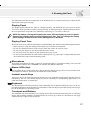
3. Getting Started
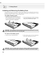
Installing and Removing the Battery Pack
Your Notebook PC may or may not have its battery pack installed. If your Notebook PC does not have
its battery pack installed, there will be a large opening at the bottom of the Notebook PC. Use the
following procedures to install or remove the battery pack.
To install a battery pack:
1. Hold the battery pack on the side with the two
tabs as indicated by the arrows. Insert the battery pack with the connector side against the
connectors in the battery compartment.
2. Lower the battery pack so that it seats properly in the compartment. Press down on the
battery pack to lock the tabs in place.
WARNING! Never attempt to remove the battery pack while the Notebook PC is turned
ON, as this may result in the loss of working data.
To remove the battery pack:
1. Lift the two tabs on the battery pack.
2. Lift the battery pack out of the compartment
by the tabs as indicated by the arrow.
WARNING! Only use battery packs and power adapters supplied with this Notebook
PC or specifically approved by the manufacturer or retailer for use with this model.
26
3. Getting Started
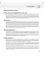
Using the Battery Pack
Before using your Notebook PC on the road
Before you use your Notebook PC on the road, you will have to charge the battery pack. The battery
pack begins to charge as soon as the Notebook PC is connected to external power. Fully charge the
battery pack before using it for the first time. A new battery pack must completely charge before the
Notebook PC is disconnected from external power. The battery pack is fully charged when the battery
charge light turns OFF. It takes a few hours to fully charge the battery when the Notebook PC is turned
OFF and may take twice the time when the Notebook PC is turned ON.
Battery Care
The Notebook PC’s battery pack, like all rechargeable batteries, has a limit on the number times it can
be recharged. Fully draining and charging the battery once a day every day will last over a year but how
long beyond that will depend on your environment temperature, humidity, and how your Notebook PC
is used. It is ideal that the battery be used in a temperature range between 10˚C and 29˚C (50˚F and
85˚F). You must also take into account that the Notebook PC’s internal temperature is higher than the
outside temperature. Any temperatures above or below this range will shorten the life of the battery.
But in any case, the battery pack’s usage time will eventually decrease and a new battery pack must be
purchased from an authorized dealer for this Notebook PC. Because batteries also have a shelf life, it is
not recommended to stock up on battery packs for the future.
Operating Systems
This Notebook PC may offer (depending on territory) its customers the choice of a pre-installed operating system such as Microsoft Windows ME (Millennium Edition) or Windows 2000. The choices
and languages will depend on the territory. The levels of hardware and software support may vary
depending on the installed operating system. Operating systems not pre-installed on this Notebook PC
may produce different results than the ones described in the provided user’s manuals. The stability and
compatibility of other operating systems cannot be guranteed.
Support Software
This Notebook PC comes with a support CD that provides BIOS, drivers and applications to enable
hardware features, extend functionality, help manage your Notebook PC, or add functionality not provided by the native operating system. If updates or replacement of the support CD is necessary, contact
your dealer for web sites to download individual software drivers and utilities.
The support CD contains all drivers, utilities and software for all popular operating systems including
those that have been pre-installed. The support CD does not include the operating system itself. The
support CD is necessary even if your Notebook PC came pre-configured in order to provide additional
software not included as part of the factory pre-install.
A recovery CD is optional and includes an image of all the drivers and utilities included on the factory
installed hard drive as well as the operating system itself. The recovery CD provides a comprehensive
recovery solution that quickly restores the Notebook PC’s operating system and software to its original
working state provided that your hard disk drive is in good working order. Contact your retailer if you
require such a solution.
27
3. Getting Started
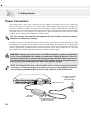
Power Connection
Your Notebook PC comes with a universal AC-DC adapter. That means that you may connect the
power cord to any 110V-120V as well as 220V-240V outlets without setting switches or using power
converters. Different countries may require that an adapter be used to connect the provided US-standard AC power cord to a different standard. Most hotels will provide universal outlets to support different power cords as well as voltages. It is always best to ask an experienced traveler about AC outlet
voltages when bringing power adapters to another country.
TIP: You can buy travel kits for the Notebook PC that includes power and modem
adapters for almost every country.
With the AC power cord connected to the AC-DC converter, connect the AC power cord to an AC outlet
(preferably with surge-protection) and then connect the DC plug to the Notebook PC. Connecting the
AC-DC adapter to the AC outlet first allows you to test the AC outlet’s power and the AC-DC converter
itself for compatibility problems before connecting the DC power to the Notebook PC. The green
power LED on the adapter lights up if the power is within accepted ranges.
WARNING! Damage may occur if you use a different adapter to power the Notebook
PC or use the Notebook PC’s adapter to power other electrical devices. If there is
smoke, burning scent, or extreme heat coming from the AC-DC adapter, seek servicing. Seek servicing if you suspect a faulty AC-DC adapter. You may damage both your
battery pack(s) and the Notebook PC with a faulty AC-DC adapter.
NOTE: This Notebook PC may come with either a two or three-prong plug depending
on territory. If a three-prong plug is provided, you must use a grounded AC outlet or
use a properly grounded adapter to ensure safe operation of the Notebook PC.
Plug the “AC Power
Cord” into an
electrical outlet
DC IN
TV
DC Power Plug
AC-DC
Converter
Connect this end of the
power cord to the
AC-DC converter
28
3. Getting Started
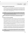
Powering ON The Notebook PC
The Notebook PC’s power-ON message appears on the screen followed by a short beep when you turn
it ON. If necessary, you may adjust the brightness by using the hot keys. If you need to run the BIOS
Setup to set or modify the system configuration, press [F2] upon bootup to enter the BIOS Setup. If you
press the [Esc] button during the splash screen, standard boot information such as the BIOS version can
be seen. You will also be presented with a boot menu that allows you to select bootup from “Legacy
Devices”, “Hard Drive”, “ATAPI CD-ROM Drive”, or enter BIOS setup. Use the up and down cursors
to make your selection and press [Enter] to execute.
WARNING! Never turn OFF or reset your Notebook PC while the hard disk or floppy
disk is in use and the activity LED is lit; doing so can result in loss or destruction of
your data. To protect the hard disk drive, always wait at least 5 seconds after turning
OFF your Notebook PC before turning it back ON.
NOTE: Before bootup, the display panel flashes when the power is turned ON. This is
part of the Notebook PC’s test routine and is not a problem with the display.
The Power-On Self Test (POST)
When you turn ON the Notebook PC, it will first run through a series of software-controlled diagnostic
tests called the Power-On Self Test (POST). The software that controls the POST is installed as a
permanent part of the Notebook PC’s architecture. The POST includes a record of the Notebook PC’s
hardware configuration, which is used to make a diagnostic check of the system. This record is created
by using the BIOS Setup program. If the POST discovers a difference between the record and the
existing hardware, it will display a message on the screen prompting you to correct the conflict by
running BIOS Setup. In most cases the record should be correct when you receive the Notebook PC.
When the test is finished, you may get a message reporting “No operating system found” if the hard
disk was not pre-loaded with an operating system. This indicates that the hard disk is correctly detected
and ready for the installation of a new operating system.
The S.M.A.R.T. (Self Monitoring and Reporting Technology) checks the hard disk drive during POST
and gives a warning message if the hard disk drive requires servicing. If any critical hard disk drive
warning is given during bootup, backup your data immediately and run Windows disk checking program.
To run Window’s disk checking program: (1) right-click any hard disk drive icon in “My Computer”, (2)
choose Properties, (3) click the Tools tab, (4) click Check Now, (5) select a hard disk drive, (6) select
Thorough to also check for physical damages, and (7) click Start. Third party disk utilities such as Symantec’s
Norton Disk Doctor can also perform the same functions but with greater ease and more features.
WARNING! If warnings are still given during bootup after running a software disk
checking utility, you should take your Notebook PC in for servicing. Continued use
may result in data loss.
29
3. Getting Started
Save-to-Disk Partition
NOTE: If you use MS Windows ME or 2000, you do not need a Save-to-Disk partition to
use hibernation mode.
The Notebook PC supports Advanced Power Management to save battery power and extend its working time. One type of power management is “Save-to-Disk.” Save-to-Disk is a suspend mode where
your operating system and application data is saved to a separate partition and retrieved when the
Notebook PC comes out of suspend mode. A partition is a space on the hard disk drive equivalent to
having a second hard disk drive. If you would like the Notebook PC to support the Save-to-Disk mode,
run the ZVHDD.EXE utility to setup a Save-to-Disk partition on your hard disk. The Save-to-Disk
partition must be larger than the total system memory of the Notebook PC. To check whether a Save-toDisk partition exist on your hard drive, run FDISK.EXE located in Windows’ command directory or
Windows rescue floppy disk. You can also compare your working partition’s size with the hard drive’s
size as shown in BIOS setup. See the Drivers and Utilities Support CD User’s Manual for detailed
usage instructions.
WARNING! All other partitions and their data will be cleared by the ZVHDD.EXE utility.
This must be done BEFORE you install an operating system onto your hard disk. The
included hard disk drive comes with the Save-to-Disk partition pre-configured from
the factory.
Restarting or Rebooting
After installing drivers (please see the “Drivers and Utilities Guide”), installing applications, or making configuration changes, you may be prompted to restart the system to update the operating system
and complete the installation process. To restart the system, press the [Ctrl][Alt][Del] keys simultaneously. This is known as a “warm boot.” If this “warm boot” does not restart the Notebook PC, you
can reset the Notebook PC by using a “cold boot” which is switching the Notebook PC’s power OFF
and then back ON. Remember to wait 5 seconds before switching the Notebook PC back ON.
NOTE: If neither of these methods work, you can press the reset button located in a
small hole on the bottom of the Notebook PC with a pen or paper clip. Do not use a
pencil because the tip may break off in the hole.
Powering OFF the Notebook PC
For operating systems equipped with APM or ACPI (Windows 98/ME/2000), the Notebook PC can be
powered OFF by using Start | Shut Down... | Shut down. For operating systems without proper power
management (DOS, Windows NT), you must power OFF the Notebook PC by holding the power switch
for 2 seconds (as opposed to 1 second to power ON) after closing applications and exiting operating
systems. This is necessary in order to prevent accidental power-OFFs. It will take 4 to 5 seconds to
power OFF the Notebook PC if you do it while the Notebook PC hangs and stopped responding,
30
3. Getting Started
Status Indicators and Instant Launch Keys
There are several LED status indicators on the Notebook PC. The LED status indicators give information on the Notebook PC’s current operating and keyboard statuses. The following illustration shows
the meaning of each status LED and the instant access keys.
Above the Keyboard
A
1
Drive
Activity Indicator
Capital Lock
Number Lock
Email
Access Key
Internet
Access
Key
Programmable
Access Key
The following gives a description for each of the LED status indicators.
Drive Activity Indicator
Indicates that the Notebook PC is accessing one or more storage device(s) such as the floppy, hard disk,
or CD/DVD-ROM drive. The light flashes proportional to the access time.
1
Number Lock
Indicates that number lock [Num Lk] is activated when lighted. Number lock allows some of the keyboard letters to act as numbers for easier numeric data input.
A
Capital Lock
Indicates that capital lock [Caps Lock] is activated when lighted. Capital lock allows some of the
keyboard letters to type using capitalized letters (e.g. A, B, C). When the capital lock light is OFF, the
typed letters will be in the lower case form (e.g. a,b,c).
Email Launch Key
Pressing this button will launch your Email application. If your Notebook PC is OFF while pressing
this button, this function will first turn ON your Notebook PC.
Internet Launch Key
Pressing this button will launch your Internet browser application. If your Notebook PC is OFF while
pressing this button, this function will first turn ON your Notebook PC.
Programmable Launch Key
Pressing this button will launch your programmed software application. If your Notebook PC is OFF
while pressing this button, this function will first turn ON your Notebook PC.
31
3. Getting Started
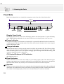
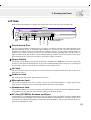
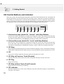
CD Control Buttons and Indicator
There are several CD control buttons integrated on the front of the Notebook PC for convenient CD
playing. The buttons activate and control your operating system’s audio player when the Notebook PC
is ON. When your Notebook PC is OFF, the CD control buttons activate an “Audio DJ” function which
allows you to listen to audio CDs even while the Notebook PC is not turned ON. The following defines
the meaning of each CD control button and indicator on the front of the Notebook PC.
CD
1 2
3
4
5
6
7
8
1. Volume Increase (Audio DJ “Unlock” with Stop Button)
Increases the volume. Hold down to continue increasing the volume. This function electronically
increases the audio output. When the Notebook PC is OFF, pressing both the volume increase and
stop buttons simultaneously, will unlock the CD player so that it can be turned ON.
2. Volume Decrease (Audio DJ “Lock” with Stop Button)
Decreases the volume. Hold down to continue decreasing the volume. This function electronically
lowers the audio output. When the Notebook PC is OFF, pressing both the volume decrease and
stop buttons simultaneously, will lock the CD player so that it cannot be accidently turned ON.
3. CD Stop
Stops CD playing (while playing). Ejects the CD (while not playing). Locks or unlocks the CD player
when used in conjunction to the volume increase or decrease buttons when the Notebook PC is OFF.
4. CD
Turns ON or OFF the Audio DJ CD player while the Notebook PC is OFF.
5. CD Skip to Previous Track (Rewind)
The first push will restart current track. The second push will skip to the previous track.
6. CD Play
Begins CD playing.
7. CD Skip to Next Track (Fast Forward)
Skips to the next track during CD playing.
8. CD Indicator
When the Notebook PC is OFF, a blue LED shows when the Audio DJ CD player is turned ON (by
using the “CD” button).
32
3. Getting Started
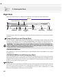
Using the Keyboard
Colored Hot Keys
The following defines the colored hot keys on the Notebook PC’s keyboard. The colored commands can only
be accessed by first pressing and holding the function key while pressing a key with a colored command.
Fn
Fn
Fn
Fn
F1
SUSPEND
F7
LCD
Suspend: Places the Notebook PC in suspend mode (either Save-to-RAM or Save-to-Disk
depending on BIOS setup). This is the same as “stand by” in MS Windows.
LCD Icon: Toggles the display panel ON and OFF. This is a quick way to hide your
work.
LCD/Monitor Icons: Toggles between the Notebook PC’s LCD display and an external monitor in this series: Notebook PC LCD -> External Monitor -> Both. (This
function does not work in 256 Colors, select High Color in Display Property Settings.)
F8
LCD
F9
TV
TV Icon: Toggles the TV output ON and OFF. This is a quick way to pause your
presentation display during intermission.
Fn
Ins
NumLK
Num Lk: Toggles the numeric keypad (number lock) ON and OFF. Allows you to use
a larger portion of the keyboard for number entering.
Fn
Del
ScrLK
Scr Lk: Toggles the “Scroll Lock” ON and OFF. Allows you to use a larger portion of
the keyboard for cell navigation.
NOTE: Hot Keys work only on the Notebook PC’s own keyboard and not on any externally connected keyboards.
33
3. Getting Started
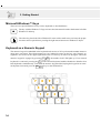
Microsoft Windows™ Keys
There are two special Windows™ keys on the keyboard as described below.
The key with the Windows™ Logo activates the Start menu located at the bottom left of the
Windows™ desktop.
The other key, that looks like a Windows™ menu with a small cursor, activates the properties menu and is equivalent to pressing the right mouse button on a Windows™ object.
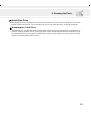
Keyboard as a Numeric Keypad
The numeric keypad is embedded in the keyboard and consists of 15 keys that make number intensive
input more convenient. These dual-purpose keys are labeled in orange on the key caps. Numeric assignments are located at the upper right hand corner of each key as shown in the figure. When the
numeric keypad is engaged by pressing
Ins
NumLK
Fn
, the number lock LED lights up. If an external
Ins
keyboard is connected, pressing the NumLK
on the external keyboard enables/disables the NumLock on
both keyboards simultaneously. To disable the numeric keypad while keeping the keypad on an exter-
nal keyboard activated, press the
Ins
NumLK
Fn
F6
F7
keys on the Notebook PC.
F8
&
J
N
34
I
4
H
(
8
U
F11
Sys Rq
1
-
L
3
<
,
-
P
6
2
0
*
O
5
-
)
9
K
M
F10
TV
*
7
Y
F9
LCD
LCD
:
{
[
+ '
>
. ?/
"
3. Getting Started
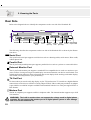
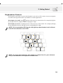
Keyboard as Cursors
The keyboard can be used as cursors while Number Lock is ON or OFF in order to increase navigation
ease while entering numeric data in spreadsheets or similar applications.
With Number Lock OFF, press Fn and one of the cursor keys shown below. For example [Fn][8] for
up, [Fn][K] for down, [Fn][U] for left, and [Fn][O] for right.
With Number Lock ON, use [Shift] and one of the cursor keys shown below. For example [Shift][8]
for up, [Shift][K] for down, [Shift][U] for left, and [Shift][O] for right.
NOTE: The second status LED (from the left) lights up when Number Lock is ON and
turn OFF when Number Lock is OFF.
F6
F7
F8
-
8
9
0
-
U 4
I 5
O 6
7
J
N
F11
Sys Rq
) *
*
H
F10
TV
( 9
& 7
Y
F9
LCD
LCD
8
1
K 2
M 0
<
,
P -
L 3
: +
;
> .
.
{
[
"
'
? /
NOTE: The large bold characters and symbols are printed here for your reference.
They are not labeled on the keyboard as shown here.
35
36
4. USING THE NOTEBOOK PC
Pointing Device
Mouse/Keyboard Connection
CD/DVD-ROM Drive
Optional External Connections
PC Card (PCMCIA) Sockets
Modem/Network Connections
IR Wireless Communication
AC/Battery Power System
Power Management Modes
System Memory Expansion
Processor Upgrades
Hard Disk Drive
Securing Your Notebook PC
Vehicle/Air Power Adapter
37
4. Using the Notebook PC
Pointing Device
The Notebook PC’s integrated touchpad pointing device is fully compatible with all two/three-button and
scrolling knob PS/2 mice. The touchpad is pressure sensitive and contains no moving parts; therefore,
mechanical failures can be avoided. A device driver is still required for working with some application
software. See the Driver & Utility Guide for information on drivers and utilities for the touchpad.
Touchpad
Right Cursor Button
Scroll Up Button
Scroll Down Button
Left Cursor Button
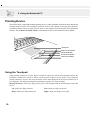
Using the Touchpad
Light pressure with the tip of your finger is all that is required to operate the touchpad. Because the
touchpad is electrostatic sensitive, objects cannot be used in place of your fingers. The touchpad’s
primary function is to move the cursor around or select items displayed on the screen with the use of
your fingertip. The following illustrations demonstrate proper use of the touchpad.
Moving the cursor - Place your finger in the center of the touchpad and do the following to move the
cursor:
38
Up - Slide your finger forward
Left - Slide you finger to the left
Down - Slide your finger backward
Right - Slide your finger to the right
4. Using the Notebook PC
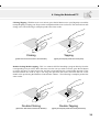
Clicking/Tapping - With the cursor over an item, press the left button or use your fingertip to touch the
touchpad lightly, keeping your finger on the touchpad until the item is selected. The selected item will
change color. The following 2 examples produce the same results.
Clicking
Tapping
(press the left cursor button and release)
(lightly but rapidly strike the touchpad)
Double-clicking/Double-tapping - This is a common skill for launching a program directly from the
corresponding icon you select. Move the cursor over the icon you wish to execute, press the left button
or tap the pad twice in rapid succession, and the system launches the corresponding program. If the
interval between the clicks or taps is too long, the operation will not be executed. You can set the
double-click speed using the Windows Control Panel “Mouse.” The following 2 examples produce the
same results.
Double-Clicking
Double-Tapping
(press the left button twice and release)
(lightly but rapidly strike the touchpad twice)
39
4. Using the Notebook PC
Dragging - Dragging means to pick up an item and place it anywhere on the screen you wish. You can
move the cursor over the item you select, and while keeping the left button depressed, moving the cursor
to the desired location, then release the button. Or, you can simply double-tap on the item and hold while
dragging the item with your fingertip. The following 2 examples produce the same results.
Dragging-Clicking
Dragging-Tapping
(hold left button and slide finger on touchpad)
(lightly strike the touchpad twice, sliding finger
on touchpad during second strike)
Scroll Up
Scroll Down
(hold the top button down to scroll up)
(hold the bottom button down to scroll down)
NOTE: Besides the hardware scroll buttons, a software-controlled scrolling function
is available after setting up the included touchpad utility to allow easy Windows or
web navigation. Basic functions can be adjusted at the Windows control panel to
allow comfortable clicking and tapping.
40
4. Using the Notebook PC
Caring for the Touchpad
The touchpad is pressure sensitive. If not properly cared for, it can be easily damaged. Take note of the
following precautions.
•
•
•
•
Make sure the touchpad does not come into contact with dirt, liquids or grease.
Do not touch the touchpad if your fingers are dirty or wet.
Do not rest heavy objects on the touchpad or the touchpad buttons.
Do not scratch the touchpad with your finger nails or any hard objects.
NOTE: The touchpad responds to movement not to force. There is no need to tap the
surface too hard. Tapping too hard does not increase the responsiveness of the touchpad. The touchpad responds best to light pressure.
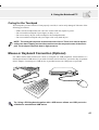
Mouse or Keyboard Connection (Optional)
For added comfort when stationed at a desk, try using PS/2 or USB peripherals. Pictured below is a
PS/2 keyboard and a USB mouse. If you wish to connect two PS/2 devices, you need to buy an optional
PS/2 Y-adapter. Connecting two USB devices is possible because two USB ports are provided.
DC IN
TV
Tip: Using a PS/2 keyboard together with a USB mouse allows one USB port to be
available for an additional USB device.
41
4. Using the Notebook PC
CD/DVD-ROM Drive
NOTE: The terms “CD-ROM” or “CD” are mainly used in all documentation because of
its wide familiarity, although “CD/DVD-ROM” or “CD/DVD” should be more appropriate
with the DVD-ROM model Notebook PC. Please substitute where appropriate.
The CD-ROM (Compact Disc Read Only Memory) drive can support all the popular formats: Audio/
Music CDs; Photo CDs; MS-DOS MSCDEX Mode 1 / Mode 2; CD-ROM/XA; CD-I; and Video CDs.
NOTE: Only one CD may be used at one time in this CD drive. The CD drive eject
button is electronic and requires that the Notebook PC be powered ON in order to
eject the CD drive tray. When the Notebook PC is OFF, press the stop button on the
front of the Notebook PC twice to eject the CD tray.
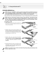
Inserting a CD
1. While the Notebook PC’s power is ON, press
the CD drive eject button and the CD drive tray
will eject out partially.
2. Hold the CD drive front panel and slide the CD
drive tray completely out. Be careful not to touch
the CD drive lens and other mechanisms. Make
sure there are no obstructions that may get
jammed under the CD drive tray.
3. Hold the CD by the edge and face the printed
side up. Snap the CD onto the hub by pressing
on both sides of the CD center. The hub should
be higher than the CD when correctly
mounted.
4. Slowly push the CD drive tray back into the
Notebook PC. The drive begins reading the table
of contents (TOC) on the CD. When the drive
stops, the CD is ready to use.
NOTE: It is normal to hear as well as feel the CD spinning with great intensity in the
CD drive while data is read.
42
4. Using the Notebook PC
Using the CD-ROM Drive
CD-ROM discs and equipment must be handled with care because of the precise mechanics involved.
Keep in mind the important safety instructions from your CD suppliers. Unlike desktop CD-ROM
drives, the Notebook PC uses a hub to hold the CD in place regardless of the angle. When inserting a
CD, it is important that the CD be pressed onto the center hub or else the CD-ROM drive tray will
scratch the CD.
WARNING! If the CD disc is not properly locked onto the center hub, the CD can be
damaged when the tray is closed. Always watch the CD closely while closing the tray
slowly to prevent damage.
Laser Safety
This system is classified as a Class 1 laser product. The Notebook PC’s CD/DVD-ROM drive uses a
laser reader that complies with laser product standards set by government agencies for Class 1 laser
products. It does not emit hazardous light; the beam is totally enclosed during all modes of customer
operation and maintenance.
CDRH Regulations
The Center for Devices and Radiological Health (CDRH) of the U.S. Food and Drug Administration
implemented regulations for laser products on August 2, 1976. These regulations apply to laser products
manufactured from August 1, 1976. Compliance is mandatory for products marketed in the United States.
WARNING: Use of controls or adjustments or performance of procedures other than
those specified herein or in the laser product installation guide may result in hazardous radiation exposure.
43
4. Using the Notebook PC
DVD-ROM Drive Information
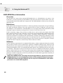
Overview
The Notebook PC comes with an optional DVD-ROM drive or a CD-ROM drive. In order to view
DVD titles, you must install the provided MPEG2 video decoder software and the DVD viewer software included on the DVD module driver support CD. The DVD-ROM drive allows the use of both CD
and DVD discs.
Definitions
DVD, which stands for Digital Versatile Disc, is the next generation of optical disc storage technology.
The DVD specification supports discs with capacities from 4.7GB to 17GB and access rates up to
22.16MBytes/s. The Notebook PC’s DVD-ROM drive is only single-sided; double-sided DVD (8.5GB
and higher) requires manually reversing the disc in order to access the reverse side.
DVD is essentially a bigger, faster CD that can hold video as well as audio and computer data. With
these capacities and access rates, DVD discs can provide you with dramatically-enhanced high-color,
full-motion videos, better graphics, sharper pictures, and Dolby® Digital Surround for a theater-like
experience. DVD aims to encompass home entertainment, computers, and business information with a
single digital format, eventually replacing audio CD, videotape, laserdisc, CD-ROM, and perhaps even
video game cartridges. DVD has widespread support from all major electronics companies, all major
computer hardware companies, and most major movie and music studios.
Software
To meet customer requirements for a complete DVD solution, a software playback solution is provided.
The provided software has been optimized for playback of MPEG2 (Motion Picture Experts Group
specifications for data compression) encoded video clips as well as encrypted DVD movie titles. Decoding digital MPEG2 video is accomplished through software only, eliminating the need for expensive hardware. Although the software will function on Intel 233-333MHz based notebooks, playback
quality is reduced since loss of video frames (video images look as though they are skipping sections of
the movie) during playback may occur. Software playback performance on Intel’s 400MHz processor
platforms or faster is required to sustain 30 fps (frames per second) which approaches the quality of
most hardware playback solutions.
NOTE: Since MPEG2 video decoding is done through software, a processor of at least
400MHz Pentium II is recommended to provide real-time playback without frame skips.
An MPEG2 hardware decoder PCMCIA card is required on Notebook PCs with slower
processors for smooth DVD playback.
44
4. Using the Notebook PC
Regional Playback Information
Playback of DVD movie titles involves decoding MPEG2 video, digital AC3 audio and decryption of
CSS protected content. CSS (sometimes called copy guard) is the name given to the content protection
scheme adopted by the motion picture industry to satisfy a need to protect against unlawful content
duplication.
Although the design rules imposed on CSS licensors are many, one rule that is most relevant is playback restrictions on regionalized content. In order to facilitate geographically staggered movie releases,
DVD video titles are released for specific geographic regions as defined in “Region Definitions”
below. Copyright laws require that all DVD movies be limited to a particular region (usually coded to
the region at which it is sold). While DVD movie content may be released for multiple regions, CSS
design rules require that any system capable of playing CSS encrypted content must only be capable of
playing one region. The region setting may be changed up to five times using the viewer software, then
it can only play DVD movies for the last region setting. Changing the region code after that will require
factory resetting which is not covered by warranty. If resetting is desired, shipping and resetting costs
will be at the expense of the user.
Region Definitions
Region 1
Canada, US, US Territories
Region 2
Czech, Egypt, Finland, France, Germany, Gulf States, Hungary, Iceland, Iran, Iraq, Ireland, Italy, Japan, Netherlands, Norway, Poland, Portugal, Saudi Arabia, Scotland, South Africa, Spain, Sweden,
Switzerland, Syria, Turkey, UK, Greece, Former Yugoslav Republics, Slovakia
Region 3
Burma, Indonesia, South Korea, Malaysia, Philippines, Singapore, Taiwan, Thailand, Vietnam
Region 4
Australia, Caribbean (Except US Territories), Central America, New Zealand, Pacific Islands, South
America
Region 5
CIS, India, Pakistan, Rest of Africa, Russia, North Korea
Region 6
China
45
4. Using the Notebook PC
Using a CD
A CD drive letter should be present regardless of the presence of a CD disc in the drive. After the CD is
properly inserted, data can be accessed just like with hard disk drives; except that nothing can be
written to or changed on the CD. Vibration is normal for all high-speed CD-ROM drives due to unbalanced CDs or CD print. To decrease vibration, use the Notebook PC on an even surface and do not
place labels on the CD.
Removing a CD
Remove the CD by slowly lifting the CD off the tray by holding the edge of the CD. Do not touch the
bottom-side of the CD where data is read from.
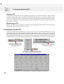
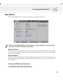
Listening to Audio CD
Both the CD-ROM and DVD-ROM drive can play audio CDs, but only the DVD-ROM drive can play
DVD audio. Insert the audio CD and Windows™ automatically opens an audio player and begins
playing. Depending on the DVD audio disc and installed software, it may require that you open a DVD
player to listen to DVD audio. You can adjust the volume through the volume control knob on the CD/
DVD-ROM drive face, function keys on the keypad, or by the Windows™ speaker icon on the taskbar.
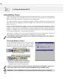
Information is shown when
the cursor is passed over
this speaker icon
A right-click on this speaker
icon gives a menu
A left-click on this speaker icon gives
you a master volume control with mute
a double-click on the speaker icon gives this detailed control panel
46
4. Using the Notebook PC
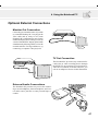
Optional External Connections
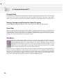
Monitor Out Connection
Connecting an external monitor is just like
on a standard desktop PC. Just plug in the
VGA cable and its ready to use (some
Notebook PC configurations may require
additional display driver settings). You can
view the Notebook PC display panel while
simultaneously allowing others to view the
external monitor. For large audiences, try
connecting a computer video projector.
DC IN
TV
TV Out Connection
DC IN
TV
The Notebook PC provides easy connection for
a television or video recording device through
the SVHS TV out connector. For televisions or
video devices without an SVHS connector, you
can use an adapter as shown in this illustration.
External Audio Connections
The Notebook PC provides easy access for connecting a stereo headphone, mono microphone, and a stereo audio source just like on some personal tape recorders.
47
4. Using the Notebook PC
PC Card (PCMCIA) Sockets
The Notebook PC has two PC Card (or sometimes referred to as PCMCIA) sockets located behind a
hinged cover to allow expansion just like desktop computer expansion slots. This allows you to customize
your Notebook PC to meet a wide range of application needs. The sockets can interface with two Type I or
Type II PC cards or one Type III PC card. PC cards are about the size of a few stacked credit cards and
have a 68-pin connector at one end. The PC Card standard accommodates a number of function, communication, and data storage expansion options. PC cards come in memory/flash cards, fax/modems, networking adapters, SCSI adapters, MPEG I/II decoder cards, and even wireless modem or LAN cards. The
Notebook PC supports PCMCIA 2.1, and 32bit CardBus standards.
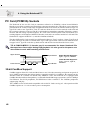
The three different PC Cards actually have different thicknesses. Type I cards are 3.3mm, Type II cards
are 5mm, and Type III cards are 10.5mm thick. Type I and Type II cards can be used in either the lower
or upper socket. Type III cards take up both sockets and must be inserted from the lower socket.
TIP: A PCMCIA MPEG I / II decoder card is recommended for slower Notebook PCs
that experience frame skips during DVD playback. It is also great for the power user
who wishes to work while watching a DVD movie.
Upper Socket
Lower Socket
Eject Button
Eject Button
Upper Socket Supports:
Type I, Type II, CardBus
Lower Socket Supports:
Type I, Type II, Type III,
CardBus
32-bit CardBus Support
CardBus support allows PC Cards and their hosts to use 32-bit bus mastering and operate at speeds of
up to 33MHz, transferring data in burst modes comparable with PCI’s 132MB/sec. By comparison, the
standard 16-bit PC Card bus can handle only 20MB/sec. Since the Notebook PC is equipped with
CardBus broader and faster data pathway, it can handle bandwidth-hungry operations, such as 100Mbps
Fast Ethernet, Fast SCSI peripherals, and ISDN-based video conference. The CardBus peripherals
support plug and play.
The CardBus socket is backward-compatible with 16-bit PC Cards serving at 5 volts operation while
CardBus operates at 3.3 volts to reduce power consumption.
48
4. Using the Notebook PC
Inserting a PC Card (PCMCIA)
1. Insert the PC card with the connector side
first. When the PC card is fully inserted, the
PC card bay door can close normally without striking the PC card.
2. Carefully connect any cables or adapters
needed by the PC card. Usually connectors
can only be inserted in one orientation. Look
for a sticker, icon, or marking on one side of
the connector representing the top side.
E
S
IN
R
T
H
T
IS
N
E
D
Be sure the PC card is
level when inserting.
Removing a PC Card (PCMCIA)
When PC cards are inserted and running, they draw power from the Notebook PC even when they are
not in use. You must stop the PC card service to turn the PC card OFF.
CAUTION! Stopping the PC card service is necessary before removing a PC card.
To remove the PC card, first remove all cables or adapters attached to the PC card, then double-click the
PC card icon on the taskbar and stop the PC card you want to remove.
1. Press in the toggle eject button and release. The
recessed spring loaded toggle button will extend when pushed in and released.
2. Press the extended button again to eject the
PC Card. Carefully pull the ejected PC card
out of the socket.
49
4. Using the Notebook PC
Modem and Network Connections
The built-in modem and network model comes with both an RJ-11 and an RJ-45 port. RJ-11 telephone
cables have two or four wires and are used to connect telephones to telephone outlets found in the walls of
residential homes and some commercial buildings (some commercial buildings may have telephone wiring designed for dedicated phone systems that may not be compatible). RJ-45 network cables are found
connecting network computers to network hubs or switches usually found in business environments.
NOTE: The built-in modem and network cannot be installed later as an upgrade. Modem and/or network can be installed as a PC card (PCMCIA).
WARNING! Only use analog telephone outlets. The built-in modem does not support
the voltage used in digital phone systems. Do not connect the RJ-11 to digital phone
systems found in many commercial buildings or else damage will occur!
Modem Connection
The telephone wire used to connect the Notebook PC’s internal modem should have either two or four
wires (only two wires (telephone line #1) is used by the modem) and should have an RJ-11 connector
on both ends. Connect one end to the modem port and the other end to an analog telephone wall socket
(the ones found in residential buildings). Once the driver is setup, the modem is ready to use.
NOTE: When you are connected to an online service, do not place the Notebook PC in
suspend (or sleep mode) or else you will disconnect the modem connection.
Modem Protocols
The Notebook PC with internal modem complies with JATE (Japan), FCC (US, Canada, Korea, Taiwan,
and others), and CTR21 (see Appendix for supported countries) for almost worldwide protocol support.
This is an example of the Notebook PC
connected to a telephone jack for use
with the built-in modem.
DC IN
TV
Telephone
Wall Jack
Telephone cable
with RJ-11 connectors
CAUTION: For electrical safety concerns, only use telephone cables rated 26AWG or
higher. (see Glossary for more information)
50
4. Using the Notebook PC
Network Connection
Connect a network cable, with RJ-45 connectors on each end, to the modem/network port on the Notebook PC and the other end to a hub or switch. For 100BASE-TX speeds, your network cable must be
category 5 (not category 3) with twisted-pair wiring. If you plan on running the interface at 100Mbps,
it must be connected to a 100BASE-TX hub (not a 100BASE-T4 hub). For 10Base-T, use category 3, 4,
or 5 twisted-pair wiring. Duplex transfers (up to 200Mbps) is supported on this Notebook PC but
requires connection to a switch with “duplex” enabled. The software default is to use the fastest setting
so no user-intervention is required.
Twisted-Pair Cable
The cable used to connect the Ethernet card to a host (generally a Hub) is called a straight-through
Twisted Pair Ethernet (TPE). The end connectors are called RJ-45 connectors, which are not compatible with the standard RJ-11 telephone connectors. If connecting two computers together without a hub
in between, a crossover twisted-pair is required.
DC IN
TV
Network Hub or Switch
Network cable with
RJ-45 connectors
This is an example of the Notebook PC connected to
a Network Hub or Switch for use with the built-in
Ethernet controller.
HUB RJ45 Connector
12345678
51
4. Using the Notebook PC
IR Wireless Communication
The Notebook PC is equipped with a conveniently located Infrared (IR) Communication Port (see 2.
Knowing the Parts for location). The IR port comes with IrDA (Infrared Data Association) Serial
Infrared Data Link Version 1.1 compliance, that allows you to perform point-to-point wireless communications. You can use a SIR/FIR-specified application to transmit or receive data files with other
systems equipped with an infrared port. You must set these modes in the BIOS before you start to install
the IR driver and file-transferring applications. FIR (Fast Infrared) supports up to 4Mbps and SIR
(Serial Infrared) supports up to 115.2Kbps. See the Drivers and Utilities Support CD User’s Manual for
detailed setup instructions.
Guidelines for using IR communication
Follow the guidelines listed below when using the Infrared (IR) Communication:
•
•
•
•
•
•
Make sure the IR Mode in the BIOS Setup is properly set to the mode you would like to use.
The angle between two Infrared communication ports should not exceed ±15˚.
The distance between the Notebook PC’s IR and target device IR should not exceed 40 inches (1 m).
Do not move either the Notebook PC or the other device during transmission of data.
An error may occur if IR transmission is conducted with high levels of noise or vibration.
Avoid direct sunlight, flashing incandescent light, florescent light, and other infrared devices such as
remote controls close to the infrared port.
Enabling Infrared
Infrared communication must be enabled in MS Windows. Right click on the infrared icon on the
Windows taskbar and select “Enable infrared communication.”
When infrared communication is enabled, moving the cursor over the icon will give its status.
information is shown when the cursor is
passed over this speaker icon
a right-click on this infrared icon gives a menu
CAUTION! Disable the infrared communication when you are not using the IR for long
periods because the IR consumes a great deal of Windows resources which will decrease the Notebook PC’s performance.
52
4. Using the Notebook PC
AC Power System
The Notebook PC power is comprised of two parts, the power adapter and the battery power system.
The power adapter converts AC power from a wall outlet to the DC power required by the Notebook
PC. The battery pack consists of a set of Lithium-Ion (Li-Ion) battery cells housed together. Only one
battery pack can be inserted into the Notebook PC. The AC Adapter’s primary function is to provide
power to the Notebook PC which also charges the battery pack. When the power adapter is connected to
the Notebook PC, it provides power to the Notebook PC and charges the internal battery at the same
time as long as it is plugged into an electrical outlet.
CAUTION! To protect your Notebook PC from damage, use only the power adapter
that came with this Notebook PC because each power adapter has its own power
output ratings.
Battery Power System
The Notebook PC is designed to work with a removable battery pack located inside the battery pack
compartment. A fully charged pack will provide several hours of battery life, which can be further
extended by using power management features through the BIOS setup. The battery system implements the Smart Battery standard under the Windows environment, which allows the battery to accurately report the amount of charge percentage left in the battery. Additional battery packs are optional
and can be purchased separately through a Notebook PC retailer. Before using the Notebook PC on
battery power for the first time, check the battery icon in the Windows task bar to make sure that the
battery is fully charged. Charging the battery takes a few hours when the Notebook PC is powered OFF.
Charging the Battery Pack
You can charge the battery pack by using the power adapter. When the power adapter is plugged in, the
inserted battery pack automatically recharges whether your Notebook PC is ON or OFF. It takes a few
hours to receive a full charge when the power is OFF but takes twice as long when the Notebook PC is
in use. When the orange charge LED is flashing, charging is required. The battery is charging when the
orange LED is solid. When the LED is no longer lit, the battery pack is fully charged.
NOTE: The battery stops charging if the temperature is too high or the battery voltage
is too high.
53
4. Using the Notebook PC
Using Battery Power
A fully-charged Li-Ion battery pack provides the system approximately 2.5 to 3 hours of working power.
But the actual figure varies depending on how you use the power saving features, your general work
habits, the CPU, main memory size, and the size of the display panel.
The “Battery Warning” beeps are automatically enabled in Windows 98/ME and continually sounds
when down to 10% (configurable in Windows 98/ME) power. The processor is also throttled down to
decrease power use.
In DOS, POWER.EXE must be enabled to use the Low Battery Warning Beep function in DOS. In
Windows 3.1, W31-APM must be enabled to use the battery warning beep feature. POWER.EXE must be
loaded via a DEVICE= line in CONFIG.SYS to report the status of the battery while using DOS or
Windows 3.x. POWER.EXE is not necessary when running Windows 95/98. For additional information,
see your DOS and Windows 3.1 User’s Manuals for details.
“Low Battery” condition (3% or less) forces the Notebook PC to enter suspend mode, regardless of
power management settings but the threshold is configurable in Windows 98/ME.
NOTE: Battery Warning and Battery Low conditions immediately stops upon application of the power adapter.
Checking Battery Power
To check the remaining battery power, move your cursor
over the power icon. The power icon is a “battery” when
not using AC power and a “plug” when using AC power.
Double click on the icon for more information and settings.
Power icon using battery.
Power icon using AC power. The charging
(lightning) icon appears over the “plug” icon if
the battery is not fully charged. When fully
charged, only the “plug” icon will remain.
NOTE: If you ignore the low battery warning, eventually the Notebook PC enters suspend mode (either Save-to-Disk or Save-to-RAM depending on BIOS setup).
WARNING! Save-to-RAM does not last long when the battery power is depleted.
54
4. Using the Notebook PC
WARNING! Never attempt to remove the battery pack while the power is ON, or if the
system has not yet entered into the suspend mode as this may result in the data loss.
Power Management Modes
The Notebook PC has a number of automatic or adjustable power saving features that you can use to
maximize battery life and lower Total Cost of Ownership (TCO). You can control some of these features through the Power menu in the BIOS Setup when APM (non-ACPI) is used. ACPI power management settings are made through the operating system. The power management features are designed to
save as much electricity as possible by putting components into a low power consumption mode as
often as possible but also allow full operation on demand. These low power modes are referred to as
Standby mode or Suspend-to-RAM (STR) and Suspend mode or Suspend-to-Disk (STD). The Standby
mode is a simple function provided by the operating system and the suspend mode is an intense power
saver provided by the BIOS. When the Notebook PC is in either one of the power saving modes, the
status will be shown by the following: STR: Power LED Blinks and STD: Power LED OFF.
Full Power Mode & Maximum Performance
The Notebook PC operates in Full Power mode when the power management function is disabled by
configuring the BIOS Setup. When the Notebook PC is operating in Full Power Mode, the Power LED
remains ON. If you are conscious of both system performance and power consumption, select “Maximum Performance” instead of disabling all power management features.
APM and ACPI
Advanced Power Management (APM) was developed by Intel and Microsoft for DOS/Windows 3.1/
95/98 which controls only the main system power functions. Advanced Configuration and Power Management (ACPI) on the hand was developed by Intel, Microsoft, and Toshiba especially for Windows
98 or later to control power management and Plug and Play features on system devices designed on the
Wired for Management (WfM) 2.0 baseline. ACPI is the new standard in power management for Notebook PCs because of its benefits over APM. If installing Windows 98 using a BIOS dated 12/1/1999 or
later, ACPI is automatically installed. Older Notebook PCs requires an updated BIOS (dated 12/1/1999
or later) along with a reinstall of Windows 98 to utilize ACPI features.
Suspend Mode
In Save-to-RAM (STR) and Save-to-Disk (STD), the CPU clock is stopped and most of the Notebook PC
devices are put in their lowest active state. The suspend mode is the lowest power state of the Notebook
PC. The Notebook PC enters Suspend when the system remains idle for a specified amount of time or
manually using the [Fn][F1] keys. The timeout setting of both Hard Disk and Video can be set by the
BIOS Setup. To resume system operation, press any key. The Power LED blinks when the Notebook PC
is in STR mode. There are no indications when the Notebook PC is in STD mode.
55
4. Using the Notebook PC
Standby Mode
In addition to reducing the CPU clock, this mode puts devices including the LCD backlight in their
lower active state. The Notebook PC enters Standby mode when the system remains idle for a specified
amount of time. The timeout can be set through the BIOS Setup. To resume system operation, press any
key on the keyboard, touchpad, or external mouse (or moving the mouse).
A Customized Power-Saving Example
The timeout settings for System Standby, Auto Suspend, Hard Disk Off, and Video Off specify the
amount of time the system must be inactive before the next power management level is enabled. The
example below demonstrates this function. The following power management events will take place if:
• The Hard Disk Timeout is set to 2 minutes
• The Standby Timeout to 8 minutes
• Auto Suspend Timeout to 10 minutes
1. After 2 minutes of system idle, the hard disk spins down.
2. After 6 additional minutes (a total of 8 minutes of system idle) the system enters Standby.
3. After 2 minutes in the system Standby mode (a total of 10 minutes of system idle), the system
suspends to memory or to disk (depending on BIOS setup).
After the system has suspended (see ENTRY EVENT below), operation can be returned or resumed
(see EXIT EVENT below) to the point in your application where it was suspended.
Power State Summary
STATE
ENTRY EVENT
EXIT EVENT
Stand by
• Stand by through Windows Start button,
• Timer as set though “Power Management”
in Windows Control Panel or BIOS setup
• Any device
• Battery low
STR
• Timer as set through BIOS setup
• Hotkey [Fn][F1]
• Ring indicator
• Power button
• Timer as set through BIOS setup
• Hotkey [Fn][F1]
• Battery Extremely Low
• Power button
• Power button
• “Shut down” through Windows Start button
• Power button
(Save-to-RAM)
STD
(Save-to-Disk)
Soft OFF
56
4. Using the Notebook PC
Thermal Power Control
There are three power control methods for controlling the Notebook PC’s thermal state. These power
control cannot be configured by the user and should be known in case the Notebook PC should enter
these states. The following temperatures represent the chassis temperature (not CPU).
• The fan turns ON for active cooling when temperatures are close to the safe upper limit when AC
power is used and turn ON at the safe upper limit when only using battery power.
• The processor throttles (decrease CPU speed) for passive cooling when temperature exceeds the safe
upper limit.
• The system shut down for critical cooling when temperature exceeds the maximum safe upper limit.
System Memory Expansion
Under some circumstances, you may find additional memory is required. This is particularly true as
applications become more complex. Expanding system memory is one method of increasing system
performance by decreasing hard disk access. The Notebook PC comes with 64MB 64-bit high speed
SDRAM built-in. One standard 144-pin SO-DIMM (Small Outline Dual Inline Memory Module) socket
is available for system memory expansion using common 3.3 Volt 100MHz SDRAM SO-DIMM
modules. Currently, SO-DIMM memory sizes are available in 16MB, 32MB, 64MB, or 128MB for
each module. The maximum memory size you can expand the Notebook PC to is 192MB using a
128MB SO-DIMM. The BIOS automatically detects the amount of memory in the system and configure CMOS accordingly during the POST (Power-On-Self-Test) process. There is no hardware or software (including BIOS) setup required after the memory is installed. Only purchase expansion modules
from your authorized retailer to ensure compatibility and reliability. The memory module must be
installed by a certified Notebook PC technician.
CAUTION! This Notebook PC does not support EDO DRAM.
Processor Upgrades
Visit your authorized service center or retailer for upgrades. The Notebook PC uses an Intel® microPGA2 socket in order to support future processor upgrades. Faster processors are being developed
every day.
57
4. Using the Notebook PC
Hard Disk Drive
Hard disk drives have higher capacities and operate at much faster speeds than floppy disk drives and
CD-ROM drives. Enhanced IDE drives provide a reliable, fast, and cost-effective mass storage solution
in the PC storage industry. The high speed transfer modes supported are Ultra DMA/33 up to 33MB/sec
and PIO mode 4 up to 16.6MB/sec. The Notebook PC comes with a removable 2.5” (6.35cm) wide and
.374” (.95cm) high UltraDMA/33 IDE hard disk drive with capacities up to 20GB, and supports
S.M.A.R.T. (Self Monitoring and Reporting Technology) to detect hard disk errors or failures before
they happen.
Important Handling Note
Improper handling during transit may damage the hard disk drive. Handle the Notebook PC carefully
and keep it away from static electricity and strong vibrations or impact. The hard disk drive is the most
sensitive component of the Notebook PC and will likely be the first or only component that is damaged
if the Notebook PC is dropped.
Removing the Hard Disk Drive
The Notebook PC features a removable hard disk drive secured in a tray. This design allows easy data
mirroring for company use or multiple hard disk drives for specific functions. To remove the hard disk
drive, make sure that the power is turned OFF, then remove (counter-clockwise) the screw using a
screw driver or coin and slide the tray out slowly.
CAUTION: The hard disk drive compartment screw must be properly secured before transit
to prevent the hard disk drive from sliding out.
58
4. Using the Notebook PC
Securing Your Notebook PC
For system and hard disk drive security, see BIOS setup “Security”. A third party lock such as the ones
by Kensington® can be used to secure your Notebook PC physically to an unmovable object. The cable
wraps around an object and the “T” shaped end inserts into the Kensington® lock port as shown in this
illustration and a key or combination dial is used to secure the lock in place. For more information, you
can read advertisements in Notebook (sometimes referred to as “Mobile” or “Portable”) PC magazines.
Other Security Products
Another good security product is the PCMCIA lock. The dummy PCMCIA card with a cable inserts
into the PCMCIA socket on the Notebook PC and mechanisms inside the dummy PCMCIA secures
itself to the PCMCIA socket.
59
4. Using the Notebook PC
Vehicle/Air & Vehicle-Only Power Adapter (Optional)
The main purpose of the vehicle/air power adapter is to provide a source of power for using the Notebook PC and/or charging the Notebook PC’s battery from a 12VDC receptacle such as those found in
vehicles and certain airplanes.
You can use the Vehicle/Air Power Adapter in most vehicles, airplanes, or boats. The Vehicle-Only
Power Adapter does not have an airplane plug and can therefore be used only in vehicles or boats using
a standard cigarette lighter socket.
The Vehicle/Air Power Adapter is designed to work with the EmPower in-flight power system. The
EmPower system is currently available on many major airlines. If you are unsure of its availability on
your flight, please consult your airline information.
These products are essential tools for today’s mobile professional. Your purchase will enhance the power,
performance, and versatility of your portable computer while traveling in the air, on the road, or on the sea.
Vehicle -Only Power Adapter
A vehicle-only (automobile or boat) model
is also available which only has a fixed cigarette plug and cannot be used in airplanes.
12V EmPower Plug
(Airplanes)
12V Cigarette Plug
(Vehicles/Boats)
Green Power LED
Vehicle/Air Power Adapter shown here.
Features
DC Power Plug
(to Notebook PC)
The vehicle/air power adapter plugs into any vehicle’s 12 volt DC cigarette or utility receptacle and
produces an output of 19 Volts DC 2.64 Amp/hour or 50 Watts. These receptacles may be found in
automobiles, airplanes, boats, power generators, and portable power units.
Usage
Connect the 12 Volt plug into the automobile’s or boat’s cigarette or utility socket firmly. For airplanes,
remove the adapter as shown in the illustration above. The DC power plug is the same as the main
power adapter supplied with the Notebook PC.
60
5. CONFIGURING THE BIOS
Managing and Updating Your BIOS
BIOS Setup Program
Main Menu
Primary IDE
Secondary IDE
Advanced Menu
I/O Device Configuration
Security Menu
Power Menu
Boot Menu
Exit Menu
61
4. Using the Notebook PC
Managing and Updating Your BIOS
It is recommended that you save a copy of the original BIOS along with a Flash Memory Writer utility
(AFLASH.EXE) to a bootable floppy disk in case you need to reinstall the BIOS later. AFLASH.EXE
is a Flash Memory Writer utility that updates the BIOS by uploading a new BIOS file to the programmable flash ROM on the motherboard. This file works only in DOS mode. To determine the BIOS
version of your Notebook PC, check the code displayed on the upper left-hand corner of your
screen during bootup or run AFLASH.EXE. Larger numbers represent a newer BIOS file.
1.
Type FORMAT A:/S at the DOS prompt to create a bootable system floppy disk. DO NOT copy
AUTOEXEC.BAT & CONFIG.SYS to the disk.
2.
Type COPY D:\AFLASH\AFLASH.EXE A:\ (assuming D is your CD-ROM drive) to copy
AFLASH.EXE to the just created boot disk.
NOTE: AFLASH works only in DOS mode. It will not work with DOS prompt in Windows and will not work with certain memory drivers that may be loaded when you
boot from your hard drive. It is recommended that you reboot using a floppy.
3.
Reboot your computer from the floppy disk. NOTE: BIOS setup must specify “Floppy” as the
first item in the boot sequence.
4.
In DOS mode, type A:\AFLASH <Enter> to run AFLASH.
CAUTION! If “unknown” is displayed after Flash Memory:, the memory chip is either
not programmable or is not supported by the ACPI BIOS and therefore, cannot be
programmed by the Flash Memory Writer utility.
5.
Select 1. Save Current BIOS to File from the Main menu and press <Enter>. The Save Current
BIOS To File screen appears.
6.
Type a filename and the path, for example, A:\XXX-XX.XXX and then press <Enter>.
Managing and Updating Your BIOS From Your Hard Disk Drive
If you do not want to use a floppy disk or CD when managing or updating the BIOS. You can copy the
files to your hard disk drive. The root directory will be the most convenient location. Substitute A:\ with
C:\ for the procedures on these two pages. Instructions on booting to DOS from your hard disk drive:
1. Windows 95/98: Turn ON your Notebook PC and press [F8] before the Windows screen appears.
Choose the option “Command prompt only”.
Windows ME: You need the bootable Windows ME CD (WinME RCD) to boot into DOS mode.
2. At the “C:\” prompt (where the BIOS update files are located), type <aflash> and then press [Enter].
CAUTION! If your hard disk drive contains necessary data or is already bootable, DO
NOT FORMAT your hard disk drive as instructed for the floppy diskette. See next page
for details on updating your BIOS.
62
4. Using the Notebook PC
Updating BIOS Procedures (from floppy disk)
WARNING! Only update your BIOS if you have problems with your Notebook PC and
you know that the new BIOS revision will solve your problems (read the BIOS release
information provided on the download site before using). Careless updating can result in your Notebook PC having more problems!
1.
Download an updated BIOS file from the Internet (WWW or FTP) (see CONTACT INFORMATION for details) and save to the disk you created earlier.
2.
Boot from the disk you created earlier.
3.
At the “A:\” prompt, type AFLASH and then press <Enter>.
4.
At the Main Menu, type 2 and then press <Enter>. The Update BIOS Including Boot Block and
ESCD screen appears.
5.
Type the filename of your new BIOS and the path, for example, A:\XXX-XX.XXX, and then press
<Enter>.
NOTE: To cancel this operation, press <Enter>.
6.
When prompted to confirm the BIOS update, press <Y> to start the update.
7.
The utility starts to program the new BIOS information into the flash ROM. The boot block will be
updated automatically only when necessary. This will minimize the chance that a failed update
will prevent your system from booting up. When the programming is finished, Flashed Successfully will be displayed.
8.
Follow the onscreen instructions to continue.
NOTE: When you see the message “Boot Block is different”, you may still press <Y>
to update the BIOS. Yet if the update fails, your system will run a greater risk of boot
failure depending on whether the boot block is damaged or not.
WARNING! If you encounter problems while updating the new BIOS, DO NOT turn off
your system since this might prevent your system from booting up. Just repeat the
process, and if the problem still persists, update the original BIOS file you saved to
disk above. If the Flash Memory Writer utility was not able to successfully update a
complete BIOS file, your system may not be able to boot up. If this happens, your
system will need servicing.
63
4. Using the Notebook PC
BIOS Setup Program
This Notebook PC supports a programmable EEPROM that stores the BIOS software and can be updated using the provided utility as described in Flash Memory Writer Utility. This Section will guide
you through the BIOS setup program by providing clear explanations for all the options. A default
configuration has already been set. If you are either installing new devices or expanding main memory,
you will need to enter the BIOS Setup to reconfigure your Notebook PC.
A battery backed-up CMOS RAM is used to record some basic system hardware information: clock,
date, time, the error handling, and etc., even when the power is off. When the Notebook PC is turned
back on, the system is configured with the values stored in the CMOS RAM.
The settings made in the BIOS Setup program intimately affect how the Notebook PC performs. It is
important, therefore, to first understand all the Setup options, and second, to make settings appropriate
for the way you use the Notebook PC.
The BIOS (Basic Input and Output System) Setup is a menu driven software utility that enables you to
make changes to the system configuration and tailor your Notebook PC to reflect installed hardware,
alter performance, and setup power saving functions. BIOS setup is used if you are setting up the
Notebook PC for the first time, reconfiguring your system, or prompted to “Run Setup” during bootup.
This section describes how to configure your system using this utility.
Even if you are not prompted to use the Setup program, at some time in the future you may want to
change the configuration of your Notebook PC. For example, you may want to enable the Security
Password Feature or make changes to the power management settings. It will then be necessary to
reconfigure your system using the BIOS setup program so that the computer can recognize these changes
and record them in the CMOS RAM of the EEPROM.
The Setup program has been designed to make it as easy to use as possible. It is a menu-driven program, which means you can scroll through the various sub-menus and make your selections among the
predetermined choices.
When you start up the computer, the system provides you with the opportunity to run this program. This
appears during the Power-On Self Test (POST). Press [F2] to call up the Setup utility. If you are a little
bit late in pressing the mentioned key, POST will continue with its test routines, thus preventing you
from calling up Setup. If you still need to call Setup, restart the system by pressing [Ctrl] + [Alt] +
[Delete], or by pressing the Reset button if available. You can also restart by turning the system OFF
and then back ON again. But do so only if the first two methods fail.
To access the BIOS Setup program, press the [F2] key immediately when you see the splash
screen during bootup (about 1 second after powering ON). You can also press the [ESC] key and
select “Enter Setup”. If you are late, you will have to restart your Notebook PC and try again.
There are no other methods to enter the BIOS setup.
NOTE: Because the BIOS software is constantly being updated, the following BIOS
screens and descriptions are for reference purposes only and may not exactly reflect
your BIOS screens.
64
4. Using the Notebook PC
BIOS Menu Bar
The top of the screen has a menu bar with the following selections:
MAIN
Use this menu to make changes to the basic system configuration.
ADVANCED
Use this menu to enable and make changes to the advanced features
SECURITY
Use this menu to set a password to control bootup and control access
to the BIOS setup menu.
POWER
Use this menu to configure and enable Power Management features.
BOOT
Use this menu to configure the default system device used to locate
and load the Operating System.
EXIT
Use this menu to exit the current menu or specify how to exit the Setup program.
To access the menu bar items, press the right or left arrow key on the keyboard until the desired item is
highlighted.
BIOS Legend Bar
At the bottom of the Setup screen you will notice a legend bar. The keys in the legend bar allow you to
navigate through the various setup menus. The following table lists the keys found in the legend bar and
those that are not with their corresponding alternates and functions.
Navigation Key(s) Function Description
[F1] or [Alt H]
Displays the General Help screen from anywhere in the BIOS Setup
[Esc] or [Alt X]
Jumps to the Exit menu or returns to the main menu from a sub-menu
← or → (keypad arrow)
Selects the menu item to the left or right
↑ or ↓ (keypad arrows)
Moves the highlight up or down between fields
– (minus) or [F5]
Scrolls backward through the values for the highlighted field
+ (plus) or [F6] or space
Scrolls forward through the values for the highlighted field
[Enter]
Brings up a selection menu for the highlighted field
[Home] or [PgUp]
Moves the cursor to the first field
[End] or [PgDn]
Moves the cursor to the last field
[F9]
Resets the current screen to its Setup Defaults
[F10]
Saves changes and exits Setup
65
4. Using the Notebook PC
General Help
In addition to the Item Specific Help window, the BIOS setup program also provides a General Help
screen. This screen can be called up from any menu by simply pressing [F1] or the [Alt] + [H] combination. The General Help screen lists the legend keys with their corresponding alternates and functions.
Saving Changes and Exiting the Setup Program
See Exit Menu for detailed information on saving changes and exiting the setup program.
Scroll Bar
When a scroll bar appears to the right of a help window, it indicates that there is more information to be
displayed that will not fit in the window. Use [PgUp] and [PgDn] or the up and down arrow keys to
scroll through the entire help document. Press [Home] to display the first page, press [End] to go to the
last page. To exit the help window, press [Enter] or [Esc].
Sub-Menu
Note that a right pointer symbol (as shown in the left view) appears to the left of certain
fields. This pointer indicates that a sub-menu can be launched from this field. A sub-menu
contains additional options for a field parameter. To call up a sub-menu, simply move the
highlight to the field and press [Enter]. The sub-menu will then immediately appear. Use the
legend keys to enter values and move from field to field within a sub-menu just as you would
within a menu. Use the [Esc] key to return to the main menu.
Take some time to familiarize yourself with each of the legend keys and their corresponding functions.
Practice navigating through the various menus and sub-menus. If you accidentally make unwanted
changes to any of the fields, use the set default hot key [F5]. While moving around through the Setup
program, note that explanations appear in the Item Specific Help window located to the right of each
menu. This window displays the help text for the currently highlighted field.
66
4. Using the Notebook PC
Main Menu
When the Setup program is accessed, the main menu screen appears as shown:
Item Specific Help
System Time:
System Date:
[17:15:00]
[03/05/2001]
Diskette A
[1.44M, 3.5 in.]
Primary
IDE
Secondary IDE
[IBM-DJSA-210]
[TOSHIBA DVD-ROM SD-C2402]
Video Display Type
Video RAM Size
[Auto]
[16M]
CPU Type
CPU Speed
Installed Memory
Intel Pentium III
650 MHz / 100MHz
64 MB / 100 MHz
<Enter> to select field;
<+>,<-> to change value.
NOTE: In the following BIOS item descriptions, the item headings in square brackets
represent the default settings for those fields.
System Time:
Sets your system to the time that you specify (usually the current time). The format is hour, minute,
second. Insert the appropriate information. Use the [Tab] or [Shift Tab] keys to move between the hour,
minute, and second fields.
System Date:
Sets your system to the date that you specify (usually the current date). The format is month, day, year.
Type in the appropriate information. Use the [Tab] or [Shift Tab] keys to move between the month, day,
and year fields.
>Primary IDE (described later)
>Secondary IDE (described later)
67
4. Using the Notebook PC
Video Display Type [Auto]
This field allows you to select and enable video display devices, such as an LCD panel, an external
CRT/LCD monitor, or both. The configuration options are: [Auto] [CRT] [CRT + LCD] [CRT + TV]
Video RAM Size [8M]
The built-in graphics utilizes a shared memory architecture. That means that the graphics chip does not
have its own video memory but insteads borrows some memory from the system memory. You can
increase the amount of memory allocated to the graphics chip to improve graphics performance if you
have enough system memory available. The configuration options are: [2M] [4M] [8M] [16M] [32M]
CPU Type [Intel(R) Celeron(TM)] (display field)
This field gives you information on your Notebook PC’s CPU type as detected by the system. You
cannot make changes to this field. This is a display only field.
CPU Speed [600 MHz / 100 MHz] (display field)
This field gives you information on your Notebook PC’s external and internal frequency as detected by
the system. You cannot make changes to this field. This is a display only field.
Installed Memory [64 MB / 100 MHz] (display field)
This field displays the amount of extended memory and the memory speed as detected by the system.
For example 64512 KB means you have 64MB of system memory. Unfortunately, this will not tell you
how much is onboard and how much is added to the SO-DIMM socket. You must visually inspect the
SO-DIMM socket if you are considering expanding your memory. You cannot make changes to this
field. This is a display only field.
68
4. Using the Notebook PC
Primary IDE (sub-menu)
This field is used to configure the primary IDE drive installed in the system. To configure a hard disk
drive, select this sub-menu from the Main menu and press the Enter key to enter this sub-menu.
Primary
IDE
[IBM-DJSA-210]
Type:
[Auto]
Cylinders
Head
Sector
CHS Capacity
Maximum LBA Capacity
[ 1024]
[240]
[63]
7927MB
10056MB
Multi-Sector Transfers
SMART Monitoring
PIO Mode
Ultra DMA Mode
[Maximum]
[Disabled]
[4]
[2]
Item Specific Help
<Enter> to select the
type of the IDE drive.
[User Type HDD] allows
you to set each entry on
your own.
WARNING: Ultra DMA mode
3/4 can be enabled only
when BIOS detects
shielded 80-pin cable.
NOTE: Before attempting to configure a hard disk drive, make sure you have the configuration information supplied by the manufacturer of the drive. Incorrect settings
may cause your system to not recognize the installed hard disk. To allow the BIOS to
detect the drive type automatically, select [AUTO].
Type: [Auto]
Select Auto to automatically detect an IDE type drive. This option only works with standard built-in
IDE drives. If automatic detection is successful, the correct values will be filled in for the remaining
fields on this sub-menu.
To configure a drive manually, select User. Manually enter the number of cylinders, heads and sectors
per track for your drive. Refer to your drive documentation or look on the drive for this information. If
no drive is installed or if you are removing a drive and not replacing it, select None. Set the type to CDROM to support a CD-ROM or DVD-ROM drive.
Cylinders
This field configures the number of cylinders. Refer to your drive documentation to determine the correct
value to enter into this field. NOTE: To make changes to this field, the Type field must be set to User.
Heads
This field configures the number of read/write heads. Refer to your drive documentation to determine the
correct value to enter into this field. NOTE: To make changes to this field, the Type field must be set to User.
69
4. Using the Notebook PC
Sectors
This field configures the number of sectors per track. Refer to your drive documentation to determine
the correct value to enter into this field. NOTE: To make changes to this field, the Type field must be
set to User.
Maximum Capacity
This field shows the drive’s maximum capacity calculated automatically by the BIOS from the drive
information you entered.
Multi-Sector Transfers
This option automatically sets the number of sectors per block to the highest number supported by the
drive. This field can also be configured manually. Note that when this field is automatically configured,
the set value may not always be the fastest value for the drive. Refer to the documentation that came
with your hard drive to determine the optimal value and set it manually. NOTE: To make changes to
this field, the Type field must be set to User. The configuration options are: [Disabled] [2 Sectors] [4
Sectors] [8 Sectors] [16 Sectors]
LBA Mode Control
When Logical Block Addressing is enabled, 28-bit addressing of the hard drive is used without regard
for cylinders, heads, or sectors. Note that Logical Block Access may decrease the access speed of the
hard disk. However, LBA Mode is necessary for drives with greater than 504MB in storage capacity.
NOTE: To make changes to this field, the Type field must be set to User. The configuration options
are: [Disabled] [Enabled]
32 Bit I/O [Enabled]
When enabled, this option speeds up communication between the CPU and the IDE controller. This
option supports PCI local bus only. ISA bus is not supported. NOTE: To make changes to this field, the
Type field must be set to User. The configuration options are: [Disabled] [Enabled]
Transfer Mode
When enabled, this option speeds up communication between the system and the IDE controller by using
enhanced I/O transfer modes (PIO Modes). NOTE: To make changes to this field, the Type field must be
set to User. The configuration options are: [Standard] [Fast PIO 1] [Fast PIO 2] [Fast PIO 3] [Fast PIO 4]
Ultra DMA Mode
This field auto detects Ultra DMA capability (for improved transfer speeds and data integrity) for compatible IDE devices. Set to Disable to suppress Ultra DMA capability. NOTE: To make changes to this field,
the Type field must be set to User. The configuration options are: [Disabled] [Mode 0] [Mode 1] [Mode 2]
NOTE: After using the legend keys to make your selections on this sub-menu, press the
[Esc] key to exit back to the Main menu. When the Main menu appears, you will notice
that the drive size appears in the field for the hard disk drive that you just configured.
70
4. Using the Notebook PC
Secondary IDE (sub-menu)
This field is used to configure the secondary IDE drive installed in the system. To configure a hard disk
drive, select this sub-menu from the Main menu and press the Enter key to enter this sub-menu.
The fields and options on this sub-menu are the same as the previous menu described earlier. Set the
type as CD-ROM in this field to support an inserted CD-ROM or DVD drive module.
Secondary IDE
Type
PIO Mode
ULTRA DMA Mode
[TOSHIBA DVD-ROM SD-C2402]
[Auto]
[4]
[2]
Item Specific Help
<Enter> to select the
type of the IDE drive.
[User Type HDD] allows
you to set each entry on
your own.
WARNING: Ultra DMA mode
3/4 can be enabled only
when BIOS detects
shielded 80-pin cable.
NOTE: After using the legend keys to make your selections in this sub-menu, press
the [Esc] key to return to the Main menu.
71
4. Using the Notebook PC
Advanced Menu
Selecting Advanced from the main menu bar display the Advanced menu as shown below.
Item Specific Help
Plug & Play O/S
[Yes]
I/O Device Configuration
Processor Serial Number
[Disabled]
TV Display Type
[NTSC]
Boot Up NumLock Status
Quick Power On Self Test
[Off]
[Enabled]
Select ‘Yes’ if you are
using Plug & Play
capable operating
system.
Select ‘No’ if you need
the BIOS to configure
non-bootable devices.
Plug & Play O/S [Yes]
This field gives operating system information to the BIOS so that plug and play information can be set
accordingly. The default assumes that your operating system is plug and play compliant such as MS
Windows 98/ME/2000. The configuration options are: [No] [Yes].
>I/O Device Configuration (described later)
Pressing [Enter] when this field is highlighted calls up a sub-menu for configuring the Notebook PC’s
serial and parallel ports.
Processor Serial Number [Disabled]
The Processor Serial Number is a unique number that is added to every Pentium III processor to help
verify the identity of the user across the Internet. Set this field to [Enabled] when you need increased
security for doing business online or e-commerce. Otherwise, leave it to its default setting of [Disabled]
for greater anonymity when surfing the Internet. [Disabled] prohibits any software from reading the
unique identifier of the installed processor. The configuration options are: [Disabled] [Enabled]
72
4. Using the Notebook PC
TV Display Type [NTSC]
This sets the video synchronization mode for your video output device (television or video projector).
The setting depends on the territory that your video output device is manufactured for. The configuration options are: [NTSC] [PAL]
Boot Up NumLock Status [On]
Specifies the status of the keyboard’s number lock function when the Notebook PC is turned ON. The
configuration options are: [Off] [On]
Quick Power On Seft Test [Enabled]
When enabled, the system skips certain tests and boots up faster then normal. Disabled is generally
used for testing purposes. The configuration options are: [Disabled] [Enabled]
73
4. Using the Notebook PC
I/O Device Configuration (sub-menu)
I/O Device Configuration
Serial Port A
[3F8H/IRQ4]
IR Port
Mode:
DMA Channel :
[2F8H/IRQ3]
[FIR]
[1]
Parallel Port
Mode:
[378H/IRQ7]
[Normal]
Item Specific Help
<Enter> to select the
I/O Address & IRQ for
COM1.
NOTE: The presence of sub-items in this menu is dependent on certain relevant settings.
WARNING! Changing the default address and IRQ settings for Serial Port or Parallel
Port can cause conflicts with other system devices or installed peripherals.
Serial Port A: [3F8H/IRQ4]
This field allows you to configure the Notebook PC serial COM1 port. The configuration options are:
[3F8H/IRQ4] [2F8H/IRQ3] [3E8H/IRQ4] [2E8H/IRQ3] [Disabled]
IR Port: [Disabled]
This field allows you to configure the Notebook PC’s serial IR port. To enable this port, select an
address that does not conflict with another port. A conflict will be noted by red asterisks next to this
item and the item in conflict with. The configuration options are:
[3F8H/IRQ4] [2F8H/IRQ3] [3E8H/IRQ4] [2E8H/IRQ3] [Disabled]
Mode: [FIR]
The Mode field allows you to select either Standard Infrared (SIR) or Fast Infrared (FIR) communication mode. The configuration options are: [SIR] [FIR]
DMA Channel: [1]
The DMA Channel field allows you to configure the Parallel port DMA Channel for the selected
ECP mode. The configuration options are: [1] [3]
74
4. Using the Notebook PC
Parallel Port: [378H/IRQ7]
This field allows you to configure the Notebook PC parallel port. The configuration options are: [Disabled] [3BCH/IRQ7] [378H/IRQ7] [278H/IRQ5]
Mode: [Normal]
The Mode field allows you to configure the Notebook PC parallel port transmission mode. The
configuration options are: [Normal] [EPP] [ECP]
EPP Mode: When the EPP mode is selected, the standard and bidirectional modes are also available. The EPP operates on a two phase cycle. First, the host selects the register within a device for
subsequent operations. Second, the host performs a series of read and/or write byte operations to
the selected register. There are four operations supported by EPP: Address Write, Data Write,
Address Read, and Data Read. All operations are performed asynchronously.
ECP Mode: The port is both software and hardware compatible with existing parallel ports so that
it may be used as a standard printer mode if ECP is not required. ECP mode provides an automatic
high burst-bandwidth channel that supports DMA for ECP in both the forward (host to peripheral)
and reverse (peripheral to host) direction.
DMA Channel: [3] (for ECP mode only)
This field allows you to configure the Parallel port DMA channel for the selected ECP mode. The
configuration options are: [1] [3]
NOTE: After using the legend keys to make your selections for the I/O Device Configuration sub-menu, press the [Esc] key to exit back to the Advanced menu.
75
4. Using the Notebook PC
Security Menu
The Notebook PC’s advanced system of security allows you to set a password to prevent unauthorized
access to system resources, data, and the BIOS Setup Program. This Section covers each parameter of
the Security Setup. Selecting Security from the menu bar displays the following menu:
Item Specific Help
User
Password
[Enter]
HDD
Password
[Enter]
Password on boot
[Disabled]
User Password can
control access to the
system at boot and
entering Setup.
<Enter> to change
password; <Enter> again
to disable password.
The BIOS Setup program allows you to specify passwords in the Security menu. The passwords control
access to the BIOS and certain Security menu options during system startup. The passwords are not
case sensitive. In other words, it makes no difference whether you enter a password using upper or
lowercase letters.
The BIOS Setup program allows you to specify two separate passwords: a Supervisor password and a
User password. When disabled, anyone may access all BIOS Setup program functions. When enabled,
the Supervisor password is required for entering the BIOS Setup program and having full access to all
Security menu options.
76
4. Using the Notebook PC
User Password
This field allows you to set the User password. To set the User password, highlight this field and press [Enter].
Type a password and press [Enter]. You can type up to eight alphanumeric characters. Symbols and
other keys are ignored. Type the same password a second time to confirm and press [Enter]. The User
password is now set.
To change the password, repeat the same process and enter a different password. To clear the password, repeat the same process but leave the password blank and press [Enter].
HDD Password
This function is set in the same way as the User Password above. Hard disk password places a protection on each hard disk drive partition so that a password is necessary in order to access the hard disk
drive. If someone tries to access the hard disk drive from another computer, it would appear as if there
is no usable partition on the hard disk drive. If the hard disk drive is used on this or another Notebook
PC with this function, a password will be asked when the hard disk drive is accessed.
Password on boot: [Disabled]
This option requires prior setting of the User password to function. When enabled, the system will then
require the User password before the system can bootup. When set to Always, the system will then
require either the User password before allowing access to the system when resuming from suspend.
The configuration options are: [Disabled] [On Boot] [Always]
Password Usage Summary
There are several security passwords available to protect the Notebook PC. The following are situations where passwords can be applied.
On Boot: The BIOS will prompt for a password before booting the operating system. If three failed
attempts are detected, the BIOS will halt the Notebook PC.
Hard Drive: The BIOS will prompt for a password during system bootup (POST) and Resume. If three
failed attempts are made, the BIOS will freeze the Notebook PC.
77
4. Using the Notebook PC
Power Menu
The Power menu of the Setup program allows you to manually enable and adjust certain power saving
features of the Notebook PC, which are necessary for systems without APM or ACPI. For Windows 98
with APM or ACPI, all power saving controls (except “Suspend Mode”) are made through the operating system. Enabling these features will extend the life of the battery pack between charges. To make
changes to power management settings, select Power Savings from the menu bar. The following menu
appears:
Item Specific Help
Power Management
[User Define]
A u t o S u s p e n d Ti m e o u t
[Disabled]
HDD Power Down
Vi d e o P o w e r D o w n
[Disabled]
[Disabled]
Beep On Battery Low
[Disabled]
<Enter> to select the
Power Saving Mode. You
can select [User Define]
to go to the suspend
mode entry below.
Start Battery Refreshing
Power Management [User Define]
This option must be enabled to use any of the automatic power saving features.
If this menu item is set to Disabled, power management features will not function regardless of other
field settings on this menu. The Customized option allows you to make your own selections in the
Power menu. When set to Maximum Power Savings, system power will be conserved to its greatest
amount. The next four fields will then be set to predefined values that ensure maximum power savings.
When this field is set to Maximum Performance, best system performance is achieved with some
power conservation. The next four fields will then be set to predefined values that ensure maximum
power savings
The configuration options are: [User Define] [Disabled] [Min Saving] [Max Saving]
78
4. Using the Notebook PC
Auto Suspend Timeout [Disabled]
This option is only enabled when User Define is selected in the Power Management field. This field
allows you to specify the period of inactivity before the system automatically switches to Suspend
mode. In Suspend mode, various devices including the LCD backlight are powered off and the system
enters a low power CPU state. If Advanced Power Management (APM) is used, this function will be
controlled by APM and may function differently depending on the APM settings. The configuration
options are: [Disabled] [1-2Min] [2-3Min] [4-5Min] [8-9Min] [20Min] [30Min] [40Min] [1 Hour]
HDD Power Down [Disabled]
This field allows you to specify the period of inactivity required before the hard disk spins down and
enters power saving mode. The configuration options are: [Disabled] [1 Min]...[15 Min]
Video Power Down [Disabled]
This field allows you to specify the period of inactivity required before the display panel turns off. The
configuration options are: [Disabled] [1-2Min] [2-3Min] [4-5Min] [8-9Min] [20Min] [30Min] [40Min]
[1 Hour]
Beep On Battery Low [Disabled]
This option allows you to enable or disable the low battery warning beep. The configuration options
are: [Disabled] [Enabled]
Start Battery Refreshing
This function will start a software program to remove memory effects in the battery and recalibrate the
battery gauge. Even though this Notebook PC uses a Lithium-Ion battery which is not prone to memory
effects, memory effects will still occur at the end of the battery’s life cycle. Remember that all rechargeable batteries only have a definite number of charge and discharge cycles depending on environment
and quality of the battery pack. Remove the AC power adapter before using this function.
79
4. Using the Notebook PC
80
4. Using the Notebook PC
81
4. Using the Notebook PC
Boot Menu
The Boot menu allows the user to specify the order in which the Notebook PC is to check for a device
to boot the system. To make changes, select Boot from the menu bar and the following screen appears:
Item Specific Help
1. Removable Device [Legacy Floppy]
2. IDE Hard Drive
[IBM-DJSA-210]
3. ATAPI CD-ROM
[TOSHIBA DVD-ROM SD-C2402]
Boot Sequence:
<Enter> to select the
device.
To select the boot
sequence, use the up or
down arrow. Press <+> to
move the device up the
list, or <-> to move it
down the list.
Boot Sequence
1. Removable Device
2. IDE Hard Drive
3. ATAPI CD-ROM
The Boot menu allows you to select among the three possible boot devices listed using the up and down
arrow keys . By using the [+] or [Shift =] keys, you can promote devices and by using the [-] key, you
can demote devices. Press [Enter] to select the specific device or Disabled to never boot from that
device.
Promotion or demotion of devices alters the priority which the system uses to search for a boot device
on system power up. The following are explanations of the devices listed in the boot sequence:
Removable Device refer to the floppy disk used in the built-in floppy disk drive.
IDE Hard Drive refers to the internal built-in hard disk drive.
ATAPI CD-ROM refers to either the built-in CD-ROM drive or DVD-ROM drive.
82
4. Using the Notebook PC
Exit Menu
Once you have made all of your selections from the various menus in the Setup program, you should
save your changes and exit Setup. Select Exit from the menu bar to display the following menu:
Item Specific Help
Exit Saving Changes
Exit Discarding Changes
Load Setup Defaults
Discard Changes
Save Changes
Exit setup utility and
save your changes to
CMOS.
NOTE: Pressing the [Esc] key does not exit this menu. You must select one of the
options from this menu or a menu bar item to exit this menu.
Exit Saving Changes
Once you are finished making your selections, choose this option from the Exit menu to ensure the
values you selected are saved to the CMOS RAM. The CMOS RAM is sustained by an onboard backup
battery and stays on even when the Notebook PC is turned off. Once this option is selected, a confirmation is asked. Select Yes to save changes and exit.
Exit Discarding Changes
This option should only be used if you do not want to save the changes you have made to the Setup
program. If you have made changes to the fields other than system date, system time, and password, the
system will ask for confirmation before exiting.
83
4. Using the Notebook PC
Load Setup Defaults
This option allows you to load the default values for each of the parameters on the Setup menus. When
this option is selected or if [F9] is pressed, a confirmation is requested. Select Yes to load default values
programmed into the BIOS file (the default values may change from one BIOS version to another). You
can now select Exit Saving Changes or make other changes before saving the values to the EEPROM.
Discard Changes
This option allows you to discard the selections you made and restore the values you previously saved.
After selecting this option, all selections are updated and a confirmation is requested. Select Yes to
discard any changes and load the previously saved values.
Save Changes
This option saves your selections without exiting the Setup program. You can then return to other
menus and make changes. After selecting this option, all selections are saved and a confirmation is
requested. Select Yes to save any changes to the EEPROM.
84
APPENDIX
Internal Modem Compliancy
Glossary
Owner Information
85
APPENDIX
Internal Modem Compliancy
Protocols and Compliancy
The Notebook PC with internal modem model complies with JATE (Japan), FCC (US, Canada, Korea,
Taiwan), and CTR21. The internal modem has been approved in accordance with Council Decision 98/
482/EC for pan-European single terminal connection to the public switched telephone network (PSTN).
However due to differences between the individual PSTNs provided in different countries, the approval
does not, of itself, give an unconditional assurance of successful operation on every PSTN network
termination point. In the event of problems you should contact your equipment supplier in the first
instance.
Overview
On 4th August 1998 the European Council Decision regarding the CTR 21 has been published in the Official
Journal of the EC. The CTR 21 applies to all non voice terminal equipment with DTMF-dialling which is
intended to be connected to the analogue PSTN (Public Switched Telephone Network).
CTR 21 (Common Technical Regulation) for the attachment requirements for connection to the analogue public switched telephone networks of terminal equipment (excluding terminal equipment supporting the voice telephony justified case service) in which network addressing, if provided, is by
means of dual tone multifrequency signalling.
Network Compatibility Declaration
Statement to be made by the manufacturer to the Notified Body and the vendor: "This declaration will
indicate the networks with which the equipment is designed to work and any notified networks with
which the equipment may have inter-working difficulties"
Network Compatibility Declaration
Statement to be made by the manufacturer to the user: "This declaration will indicate the networks with
which the equipment is designed to work and any notified networks with which the equipment may
have inter-working difficulties. The manufacturer shall also associate a statement to make it clear where
network compatibility is dependent on physical and software switch settings. It will also advise the user
to contact the vendor if it is desired to use the equipment on another network."
Up to now the Notified Body of CETECOM issued several pan-European approvals using CTR 21. The
results are Europe's first modems which do not require regulatory approvals in each individual European country.
Non-Voice Equipment
Answering machines and loud-speaking telephones can be eligible as well as modems, fax machines,
auto-dialers and alarm systems. Equipment in which the end-to-end quality of speech is controlled by
regulations (e.g. handset telephones and in some countries also cordless telephones) is excluded.
86
APPENDIX
This table shows the countries currently under the CTR21 standard.
Country
Austria1
Belgium
Czech Republic
Denmark1
Finland
France
Germany
Greece
Hungary
Iceland
Ireland
Italy
Israel
Lichtenstein
Luxemburg
The Netherlands1
Norway
Poland
Portugal
Spain
Sweden
Switzerland
United Kingdom
Applied
Yes
Yes
No
Yes
Yes
Yes
Yes
Yes
No
Yes
Yes
Pending
No
Yes
Yes
Yes
Yes
No
No
No
Yes
Yes
Yes
More Testing
No
No
not applicable
Yes
No
No
No
No
not applicable
No
No
Pending
No
No
No
Yes
No
not applicable
not applicable
not applicable
No
No
No
This information was copied from CETECOM and is supplied without liability. For updates to this
table, you may visit http://www.cetecom.de/technologies/ctr_21.html
1
National requirements will apply only if the equipment may use pulse dialling (manufacturers may
state in the user guide that the equipment is only intended to support DTMF signalling, which would
make any additional testing superfluous).
In The Netherlands additional testing is required for series connection and caller ID facilities.
87
APPENDIX
88
APPENDIX
Glossary
ACPI (Advanced Configuration and Power Management Interface)
Modern standard for reducing power usage in computers.
AUTOEXEC.BAT
AUTOEXEC.BAT is a special-purpose file that is automatically executed by DOS whenever the computer is turned ON or restarted. This file contains important commands that help configure the system
to work with certain software and devices. Windows 95 and later has its own startup files and may not
use or may ignore parts of the AUTOEXEC.BAT file.
AWG (American Wire Gauge)
Gauge
AWG
Diam
(mm)
Area
(mm2)
R
(ohm/km)
I@3A/mm2
(mA)
Gauge
AWG
Diam
(mm)
Area
(mm2)
R
(ohm/km)
I@3A/mm2
(mA)
46
0.04
0.0013
13700
3.8
24
0.50
0.20
87.5
588
44
0.05
0.0020
8750
6
0.55
0.24
72.3
715
42
41
0.06
0.07
0.0028
0.0039
6070
4460
9
12
0.60
0.65
0.28
0.33
60.7
51.7
850
1.0 A
40
0.08
0.0050
3420
15
0.70
0.39
44.6
1.16 A
39
0.09
0.0064
2700
19
0.75
0.44
38.9
1.32 A
38
37
0.10
0.11
0.0078
0.0095
2190
1810
24
28
20
0.80
0.85
0.50
0.57
34.1
30.2
1.51 A
1.70 A
19
0.12
0.011
1520
33
36
0.13
0.013
1300
40
35
0.14
0.15
0.015
0.018
1120
970
45
54
34
22
18
0.90
0.64
26.9
1.91 A
0.95
0.71
24.3
2.12 A
1.00
1.10
0.78
0.95
21.9
18.1
2.36 A
2.85 A
1.20
1.1
15.2
3.38 A
1.30
1.3
13.0
3.97 A
1.40
1.50
1.5
1.8
11.2
9.70
4.60 A
5.30 A
1.60
2.0
8.54
6.0 A
1.70
2.3
7.57
6.7 A
0.16
0.020
844
60
0.17
0.023
757
68
33
0.18
0.19
0.026
0.028
676
605
75
85
32
0.20
0.031
547
93
30
0.25
0.049
351
147
29
27
0.30
0.35
0.071
0.096
243
178
212
288
13
1.80
1.90
2.6
2.8
6.76
6.05
7.6 A
8.5 A
26
0.40
0.13
137
378
12
2.00
3.1
5.47
9.4 A
25
0.45
0.16
108
477
16
14
NOTE: This table is for general reference only and should not be used as a source of
the American Wire Gauge standard as this table may not be current or complete.
89
APPENDIX
BIOS (Basic Input/Output System)
BIOS is a set of routines that affect how the computer transfers data between computer components,
such as memory, disks, and the display adapter. The BIOS instructions are built into the computer’s
read-only memory. BIOS parameters can be configured by the user through the BIOS Setup program.
The BIOS can be updated using the provided utility to copy a new BIOS file into the EEPROM.
Bit (Binary Digit)
Represents the smallest unit of data used by the computer. A bit can have one of two values: 0 or 1.
Boot
Boot means to start the computer operating system by loading it into system memory. When the manual
instructs you to “boot” your system (or computer), it means to turn ON your computer. “Reboot” means
to restart your computer. When using Windows 95 or later, selecting “Restart” from “Start | Shut Down...”
will reboot your computer.
Bus Master IDE
PIO (Programmable I/O) IDE requires that the CPU be involved in IDE access and waiting for mechanical events. Bus master IDE transfers data to/from the memory without interrupting the CPU. Bus
master IDE driver and bus master IDE hard disk drives are required to support bus master IDE mode.
Byte (Binary Term)
One byte is a group of eight contiguous bits. A byte is used to represent a single alphanumeric character,
punctuation mark, or other symbol.
Clock Throttling
Chipset function which allows the processor’s clock to be stopped and started at a known duty cycle.
Clock throttling is used for power savings, thermal management, and reducing processing speed.
COM Port
COM is a logical device name used by to designate the computer serial ports. Pointing devices, modems, and infrared modules can be connected to COM ports. Each COM port is configured to use a
different IRQ and address assignment.
CPU (Central Processing Unit)
The CPU, sometimes called “Processor,” actually functions as the “brain” of the computer. It interprets
and executes program commands and processes data stored in memory.
Device Driver
A device driver is a special set of instructions that allows the computer’s operating system to communicate with devices such as VGA, audio, Ethernet, printer, or modem.
Hardware
Hardware is a general term referring to the physical components of a computer system, including peripherals such as printers, modems, and pointing devices.
90
APPENDIX
IDE (Integrated Drive Electronics)
IDE devices integrate the drive control circuitry directly on the drive itself, eliminating the need for a
separate adapter card (in the case for SCSI devices). UltraDMA/33 IDE devices can achieve up to
33MB/Sec transfer.
LPT Port (Line Printer Port)
Logical device name reserved by DOS for the computer parallel ports. Each LPT port is configured to
use a different IRQ and address assignment.
MMX
A set of 57 new instructions based on a technique called Single Instruction, Multiple Data (SIMD),
which is built into the new Intel Pentium PP/MT (P55C) and Pentium II (Klamath) CPU as well as
other x86-compatible microprocessors. The MMX instructions are designed to accelerate multimedia
and communications applications, such as 3D video, 3D sound, video conference.
North Bridge
The CPU to PCI interface, also contains the memory and cache controllers.
PCI Bus (Peripheral Component Interconnect Local Bus)
PCI bus is a specification that defines a 32-bit data bus interface. PCI is a standard widely used by
expansion card manufacturers.
Peripherals
Peripherals are devices attached to the computer via I/O ports. Peripheral devices allow your computer
to perform an almost limitless variety of specialized tasks.
POST (Power On Self Test)
When you turn on the computer, it will first run through the POST, a series of software-controlled
diagnostic tests. The POST checks system memory, the motherboard circuitry, the display, the keyboard, the diskette drive, and other I/O devices.
PS/2 Port
PS/2 ports are based on IBM Micro Channel Architecture. This type of architecture transfers data
through a 16-bit or 32-bit bus. A PS/2 mouse and/or keyboard may be used on ATX motherboards.
RAM (Random Access Memory)
There are several different types of RAM such as DRAM (Dynamic RAM), EDO DRAM (Extended
Data Output DRAM), SDRAM (Synchronous DRAM).
ROM (Read Only Memory)
ROM is nonvolatile memory used to store permanent programs (called firmware) used in certain computer components. Flash ROM (or EEPROM) can be reprogrammed with new programs (or BIOS).
91
APPENDIX
SCSI (Small Computer System Interface)
High speed parallel interface defined by the X3T9.2 committee of the American National Standards
Institute (ANSI) for connecting many peripheral devices.
SMB (System Management Bus)
The SMB is used for managing smart batteries, reading SDRAM configuration information, and other
miscellaneous system functions.
SMI (System Management Interrupt)
A non-maskable interrupt that causes the system to enter SMM. SMM functions include power management, USB legacy keyboard control, security, hot keys, and thermal monitoring.
SMM (System Management Mode)
This is the mode of operation while SMI is active.
South Bridge
The PCI to ISA interface, also contains many legacy devices.
System Disk
A system disk contains the core file of an operating system and is used to boot up the operating system.
UltraDMA/33
UltraDMA/33 is a new specification to improve IDE transfer rates. Unlike traditional PIO mode, which
only uses the rising edge of IDE command signal to transfer data, UltraDMA/33 uses both rising edge
and falling edge. Hence, the data transfer rate is double of the PIO mode 4 or DMA mode 2. (16.6MB/
s x2 = 33MB/s).
USB (Universal Serial Bus)
A new 4-pin serial peripheral bus that allows plug and play computer peripherals such as keyboard,
mouse, joystick, scanner, printer and modem/ISDN to be automatically configured when they are attached physically without having to install drivers or reboot. With USB, the traditional complex cables
from back panel of your PC can be eliminated.
92
APPENDIX
Index
A
AC Power System 51
Air Vent 20
APM and ACPI 53
B
Battery Pack 26
Battery Power System 51
BIOS
32 Bit I/O 70
Advanced Menu 72
Beep On Battery Low 79
BIOS Legend Bar 65
BIOS Menu Bar 65
BIOS Setup Program 64
Boot Menu 82
Boot Sequence 82
Cylinders 69
Discard Changes 84
DMA Channel 74, 75
Exit Discarding Changes 83
Exit Menu 83
Exit Saving Changes 83
Heads 69
I/O Device Configuration 74
IR Port 74
LBA Mode Control 70
Load Setup Defaults 84
Main Menu 67
Maximum Capacity 70
Multi-Sector Transfers 70
Parallel Port 75
Power Savings 78
Save Changes 84
Sectors 70
Security Menu 76
Serial Port A 74
Suspend Mode 79
System Date 67
System Time 67
Transfer Mode 70
Type 69
Ultra DMA Mode 70
Video Timeout 79
C
Canadian Department of Communications 2
Capital Lock 31
CardBus 46
Caring Information 13
CD/DVD-ROM Drive 21, 40
CDRH Regulations 41
Colored Hot Keys 32
Cooling Fan 23
CTR 21 Approval 4
D
Display Panel 17
Display Panel Latch 24
DVD-ROM Drive Information 42
E
Email Launch Key 31
External Audio Connections 45
F
Fast Infrared Port 22
Federal Communications Commission 2
Floppy Disk Drive and Floppy Eject 21
G
Glossary 89
H
Headphone Jack 24
I
Instant Launch Keys 31
Internal Modem Compliancy 86
Internet Launch Key 31
IR Wireless Communication 50
K
Keyboard 17
L
Laser Safety 41
M
Macrovision Notice 3
Microphone Jack 24
Microsoft Windows™ Keys 33
Modem and Network Connections 48
Modem Port 22
Monitor Out Connection 45
Mouse or Keyboard Connection 36
93
APPENDIX
N
U
Network Connection 49
Nordic Cautions 3
Number Lock 31
Numeric Keypad, alternate 33
UL Safety Notices 6
Updating Your BIOS 62
User’s Manual, About 12
O
Vehicle/Air Power Adapter Accessory 59
Owner Information 96
P
Parallel Port 23
PC Card (PCMCIA) Sockets 46
Pointing Device 36
Power Connection 28
Power Indicator 31
Power Management Modes 53
Power State Summary 54
Power Switch 17
Power-On Self Test (POST) 29
Powering OFF 30
Powering ON 29
Processor Upgrades 55
Programmable Launch Key 31
R
Region Definitions 43
Regional Playback Information 43
Restarting or Rebooting 30
S
Save-to-Disk Partition 30
Securing Your Notebook PC 58
Speaker 17
Standby Mode 54
Status Indicators 31
Suspend Mode 53
System Memory Expansion 55
T
Table of Contents 7
Thermal Power Control 55
Touchpad and Buttons 17
Touchpad, Caring 38
Touchpad, Using 36
Transportation Precautions 14
Twisted-Pair Cable 49
94
V
APPENDIX
95
APPENDIX
Owner Information
This page is provided for recording information concerning your Notebook PC for future reference or
for technical support. Keep this User’s Manual in a secured location if passwords are filled out.
Owner’s Name:_______________________ Owner’s Telephone:___________________
Manufacturer:___________________________________ Model:___________________
Retailer:____________________________________ Telephone:___________________
Display Size:______Purchase Date:__________ Serial Number:___________________
Hard Disk Drive Manufacturer:___________________ Capacity:___________________
2nd Hard Disk Drive Manufacturer:_______________ Capacity:___________________
BIOS Version:____________________________________ Date:___________________
Accessories:_____________________________ Serial Number:___________________
Accessories:_____________________________ Serial Number:___________________
SOFTWARE
Operating System:________________________________________________________
Software:________________________________ Serial Number:___________________
Software:________________________________ Serial Number:___________________
SECURITY
Bootup Password:__________________ Hard Drive Password:___________________
NETWORK
User’s Name:____________ Password:_____________ Domain:___________________
User’s Name:____________ Password:_____________ Domain:___________________
96
®
Goes Mobile!
A1 Series
Affordable Entertainment Notebook PC
•
•
•
•
Internal CD/DVD & Floppy
• 13.3”/12.1” TFT Color Display
600MHz to 850MHz+
• 64MB to 192MB Memory
Internal Modem+LAN
• Wireless LAN via PC Card
Up to 32MB Shared VGA Memory
S8 Series
Ultra Slim and Light Notebook PC
•
•
•
•
External CD/DVD & Floppy
600MHz to 850MHz+
Internal Modem+LAN
External AiBox Module Bay
• 13.3”/12.1” TFT Color Display
• 64MB to 192MB Memory
• Wireless LAN via PC Card
L8 Series
Compact Professional Notebook PC
•
•
•
•
Internal CD/DVD & Floppy
500MHz to 850MHz+
2X AGP 3D w/ 8MB VRAM
100MHz Processor Side Bus
• 14.1” TFT Color Display
• 64MB to 256MB Memory
• Internal Modem+LAN
M8 Series
Thin & Light Convertible Notebook PC
• 1 Internal & 1 External Drive
• 500MHz to 650MHz+
• Internal Modem+LAN
• 13.3”/12.1” TFT Color Display
• 64MB to 192MB Memory
• Ext. PortDock Module Bay
L7 Series
All-in-One Compact Notebook PC
• Internal CD/DVD & Floppy
• 500MHz to 650MHz+
• Internal Modem
• 13.3”/12.1” TFT Color Display
• 64MB to 192MB Memory
• LAN via Optional PC Card
Visit www.asus.com for updated specifications
Visit www.asus.com for updated specifications
®
8x DVD-ROM Drive
• Industry-leading performance for even the most demanding applications
• Maximum transfer rate: 8X DVD-ROM / 40X CD-ROM
• High speed digital audio extraction
• Supports UltraDMA/33 transfer mode
• Complies with MPC3 standard
• Supports Multi-Read function
®
Ultra-Fast CD-ROM
•
•
•
•
•
Supports high speed CD-Audio playback
Supports high speed digital audio extraction
Supports UltraDMA/33 transfer mode
Compatible with all CD formats
Supports multi-read function (CD-R/CD-RW)
Visit www.asus.com for updated specifications
AGP-V7100 Series
Experience Radical 3D/2D Graphics Performance with 2nd Generation GPU
TwinView™
The ASUS AGP-V7100 Series graphics cards were
created to provide mainstream PC users with the radical
3D/2D graphics and video performance of the
GeForce2 MX, the 2nd generation GPU from NVIDIA.
With the AGP-7100 Series and its support for the
TwinView™ architecture, ASUS has made available
the most variety of available models to support several
dual display output combinations using RGB monitor,
TV, or digital flat panel.
The ASUS AGP-V7100 Series graphics cards not only
fully exert the power of the GeForce2 MX GPU, but they
also continue the ASUS tradition of providing the
greatest security for your valuable entertainment platform.
So go and experience the radical 3D/2D graphics
performance and flexible options of the ASUS AGP-V7100
Series graphics cards.
Other Hot ASUS Multimedia Products
AGP-V7700 Series
AGP-V7100 Series
• AGP-V7100/Deluxe Combo:
GeForce2 MX, VGA, TV Tuner Module,TV-Out,
AV Adapter,VR 3D Glasses, 32MB/ Frame Buffer
• AGP-V7100/2V1D:
GeForce2 MX, 2VGA + 1DVI, 32MB Frame Buffer
• AGP-V7100/DVI:
GeForce2 MX, VGA + DVI, 32MB/16MB Frame Buffer
• AGP-V7100/T:
GeForce2 MX, VGA + TV-Out, 32MB/16MB Frame Buffer
• AGP-V7100/Pure:
GeForce2 MX, VGA, 32MB/16MB Frame Buffer
• and other dual display output combinations
(depending on request).
AGP-V3800 Series
AGP-V300C
• AGP-V7700 Deluxe TV:
GeForce2 GTS, 32MB DDR Frame Buffer,
TV-Out, Video-In, VR 3D glasses, TV-Box
• AGP-V7700 Deluxe:
GeForce2 GTS, 32MB DDR Frame Buffer,
TV-Out, Video-In, VR 3D glasses
• AGP-V7700 / T / 64MB:
GeForce2 GTS, 64MB DDR
Frame Buffer, TV-Out
• AGP-V7700 / T / 32MB:
• AGP-V7700 Ultra:
GeForce2 GTS, 32MB DDR
GeForce2 Ultra, 64MB DDR
Frame Buffer, VGA, (Optional TV-Out Module) Frame Buffer, TV-Out
• AGP-V7700 / 64MB:
• AGP-V7700 Pro / T:
GeForce2 GTS, 64MB DDR
GeForce2 Pro, 64MB DDR
Frame Buffer, w/o SmartDoctor
Frame Buffer, VGA + TV-Out
• AGP-V7700 / 32MB:
• AGP-V7700 Pro:
GeForce2 GTS, 32MB DDR
GeForce2 Pro, 64MB DDR Frame Buffer
Frame Buffer
• AGP-V3800 Magic / T:
TNT2 M64, 32MB/16MB Frame Buffer,
TV-Out
• AGP-V3800 Magic:
TNT2 M64, 32MB/16MB Frame Buffer
• AGP-V300C:
SiS 305,
16MB Frame Buffer
www.asus.com
Visit www.asus.com for updated specifications
®
New!
New!
Barebone Servers
Pentium® III
Pentium® II
Support
Maximum
Memory
(GB)
AP100
1 Slot1
1
1
3
0
AP200
2 Slot1
1
1
3
0
AP2000
2 Slot1
1
1
4
3 or 5*
AP3000
2 Xeon™
2
2
4
3 or 5*
AP2300
2 Socket370
4
2
4
3 or 5*
AP6000
2 Slot1
1
1
4
8**
AP8000
2 Xeon™
2
2
4
8**
AP6300
2 Socket370
4
2
4
8**
*
**
Mid-Range Servers
AP6000
AP8000
Ultra2 SCSI
5.25”
Onboard Fixed Storage
(Channels)
Devices
Hot-Swap Trays
Three 1.6-inch or five 1-inch SCA-2 SCSI hard drives
Eight 1.6-inch or 1-inch SCSI hard drives
Value Servers
AP2000
AP2300
AP3000
ASUS PCI-DA2200
Ultra2 SCSI RAID Card
Group Servers
AP100
AP200
AR1000 Ultra2 RAID
Subsystem
Rack Mountable
Visit www.asus.com for updated specifications