1
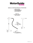
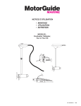
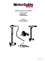
OWNER’S INSTRUCTION MANUAL
• INSTALLATION
• OPERATION
• MAINTENANCE
MODELS:
Freshwater, Saltwater,
Tour and Tour ES
90-10235021 502
This MotorGuide electric outboard motor assembled of U.S.A and
foreign components by MotorGuide, 835 W. 41st St., Tulsa, OK, USA,
complies with requirements of Directives 89/392/EEC and
89/336/EEC as amended.
Larry Register
Motorguide Business Unit Manager
MotorGuide
835 W. 41st St., Tulsa, OK, USA
90-10235R21 502
TABLE OF CONTENTS
Maintenance
General Information
How to Replace the Propeller................................................ 12
Customer Responsibilities .................................................... 12
Safety Do’s and Don’ts .......................................................... 2
Specifications ........................................................................ 2
Troubleshooting
Wiring and Battery Recommendations .................................. 2
Transom Mount Installation .................................................. 4
Trolling Motor ........................................................................ 13
Pontoon Mount Installation .................................................... 5
Mount .................................................................................... 13
Bow Mount Installation .......................................................... 5
Bow Mount Operation ............................................................ 6
Repair Parts and Service
Operation .............................................................................. 7
For Repair Service ................................................................ 14
Tour ES
For Replacement Parts and Ordering.................................... 14
Making Final Touches ............................................................ 8
Features and Operation ........................................................ 9
How to Operate Motor .......................................................... 9
To Select Trolling Mode ........................................................ 10
First Time Setup .................................................................... 10
90-10235R21 502
1
GB
WIRING AND BATTERY RECOMMENDATIONS
GENERAL INFORMATION
Please read and retain this manual. The information contained
in this manual describes the proper procedures for safely
installing, operating and maintaining your motor.
Wire and cable routing
The description and specifications contained herein were in
effect at the time this manual was approved for printing.
MotorGuide, whose policy is one of continual improvement,
reserves the right to discontinue models at any time, to change
specifications, designs, methods of procedures without notice
and without incurring obligation.
• Transducer installation should be installed according to the
manufacturer’s specifications, and cables routed separately
from the trolling motor power cables.
• Route trolling motor wires on opposite sides of the boat from
other wiring, directly to trolling motor battery.
IMPORTANT: Do not route transducer cable down
trolling motor power cord or foot pedal assembly cable.
Route transducer cable down arm of mount, then into
bow console.
Safety and operating information that is practiced along with
good common sense can help prevent personal injury and
product damage.
• Sensitive electronics, depth finders in particular, should be
connected directly to the main engine battery. If only a one
battery system, then connect with separate cables.
WARNING
• Motorguide recommends isolating the trolling motor
battery(s) from the main engine battery.
Disconnect trolling motor from battery(s) before
charging
IMPORTANT: Proper rigging guidlines
• Not having a common ground can cause corrosion. If left
unchecked, this problem will damage your motor.
SAFETY DO’S AND DON’TS
Do not allow children to operate the fishing motor without
adult supervision.
• Establishing a common ground connection will allow
increased sensitivity and improve detail on sonar display.
Do not modify the unit in any way or add accessories not
intended for this motor.
• Establish a Common Ground – Common ground means
the grounds for the main engine accessories and your
trolling motor are connected to the same terminal.
The propeller turns when the motor is running.
Always disconnect power from motor when replacing
prop, removing debris around prop, charging
batteries, trailering boat or when the motor is not in
use.
WARNING
Batteries contain sulfuric acid which can cause severe
burns. Avoid contact with skin, eyes, and clothing. The
battery also produces hydrogen and oxygen gases
when being charges. This explosive gas escapes
through the fill vent cell caps and may form an
explosive atmosphere around the battery for several
hours after it has been charged. Electrical arching or
flames can ignite the gas and cause an explosion which
may shatter the battery and could cause blindness or
other serious injury.
Always make sure motor is securely locked into
stowed position if using a gasoline motor to move
quickly to another location, or when trailering boat.
Be sure to secure loose items on boat before traveling at
high speeds across water.
SPECIFICATIONS
Model
Volts
Kwatts
Kilos
30 HT
12
0.20
6.40
46 HT
12
0.28
8.40
54 HT
12
0.34
9.40
54 HTV
12
0.34
11.40
46 FB
12
0.28
14.80
54 FB
12
0.34
16.00
• Battery Type – The recommended battery(s), 12 volt Deep
Cycle battery with at least 105 ampere hour rating or higher.
• Circuit Protection – MotorGuide recommends installing a
50 amp manual reset circuit breaker in the trolling motor
leads within (1.8 m) 72 inches of the battery(s). To order a
curcuit breaker kit contact your local SuperCenter, order kit
number MM5870.
• Wire Size – For optimum performance, MotorGuide
recommends the use of six (6) gauge wire if extending
existing wire more than (3 m) 10 feet beyond the standard
battery cable supplies with product.
• Bow Plugs – For temporary trolling motor installations,
MotorGuide recommends the use of a quality plug designed
for marine applications.
GB
2
90-10235R21 502
12 Volt battery hook-up
24 volt battery hook-up
f
d
e
e
c
d
a
f
g
h
c
k
b
a j
1
a. Black battery lead
b. Red battery lead
c. 50 amp circuit breaker
2
d. Main engine, bilge pumps,
aerators, accessories
e. Common ground
f. Power cable
a. Battery A
b. Battery B
c. Main engine bilge
pumps, aerators,
accessories
d. Common ground
e. Power cable
f. To foot pedal
(ES models only)
WARNING
Be sure all switches are in the OFF position before
connecting to batteries. Electrical arching near the
battery could ignite hydrogen gas and cause the battery
to explode.
i
b
g.
h.
i.
j.
k.
To optional sonar display
Black battery lead (-)
Red battery lead (+)
Jumper wire
50 amp circuit breaker
WARNING
Be sure all switches are in the OFF position before
connecting to batteries. Electrical arching near the
battery could ignite hydrogen gas and cause the battery
to explode.
1 Connect the red battery lead to the positive (+) post of the
battery and connect the black battery lead to the negative (-)
post of the battery. Install 50 amp circuit breaker in line with
positive lead.
2 Connect the black battery lead to the negative (-) post of the
battery A. Connect the red battery lead to the positive (+)
post on battery B. Connect a jumper wire to the negative (-)
post of battery B and the positive (+) post of battery A. Install
50 amp circuit breaker in line with positive lead.
90-10235R21 502
3
GB
36 volt battery hook-up
TRANSOM MOUNT INSTALLATION
g
e
d
2
h
f
i
4
5
j
a
k
4
a.
b.
c.
d.
Battery A
Battery B
Battery C
Main engine, bilge
pumps, aerators,
accessories
e. Common ground
f. Black battery lead (-)
g. Power cable
3
l
b
m
c
k
2
h. To foot pedal
(ES models only)
i. To optional sonar display
(PinPoint ready models
only)
j. 50 amp circuit breaker
k. Jumpe wire
l. Red battery lead (+)
m. Jumper wire
1
4
CAUTION
When adjusting the tilt on your motor, keep fingers clear
of area between column and bracket.
WARNING
Be sure all switches are in the OFF position before
connecting to batteries. Electrical arching near the
battery could ignite hydrogen gas and cause the battery
to explode.
Twist tiller models
1 Clamp screws – The clamp screws allow for easy motor
removal and installation. Mount your motor on the transom
then tighten the clamp screws securely.
4 Connect black battery lead of power cale to negative (-) post
2 Tilt position pin – The pin allows user to adjust the tilt of the
of battery A. Connect red battery lead of power cable to
positive (+) post of battery C. Connect jumper wire from
positive (+) post of battery A to negative (-) post of battery B.
Connect jumper wire from positive (+) post of battery B to
negative (-) post of battery C. Install 50 amp circuit breaker
in line with positive lead.
motor. Push tilt position pin, adjust tilt of motor, and release
pin.
3 Depth adjustment collar – The depth of the motor can be
adjusted up and down by loosening the depth collar tension
knob located on the column directly above the mount. The
column can be adjusted and motor positioned at the desired
depth by retightening the tension knob.
4 Steering tension adjustment – To adjust the steering
resistance, simply tighten or loosen the tension knob located
on front of the mount.
5 Quick stow - Standard on SW models only.
GB
4
90-10235R21 502
PONTOON MOUNT INSTALLATION
a
1
2
1, 2
a. Mounting holes
CAUTION
How to install pontoon mount
When adjusting the tilt on your motor, keep fingers clear
of area between column and bracket.
• Carefully select the area on the deck to install mount.
• Using the mount base as a template, mark the mounting
holes with a drill bit.
1 On/Off speed control – Rotate handle clockwise to obtain
• Drill mounting holes with (6.5 mm) 1/4 inch drill bit and debur
holes.
forward speeds. Rotate handle counterclockwise for reverse
speeds.
• Install the 4 stainless steel mounting bolts through bracket
mounting holes.
2 Kill switch – To stop motor position toggle switch to:
To run motor position toggle switch to:
• Install the 4 stainless steel washers and nuts on bottom side
of deck and tighten securely.
To use quik stow
Allows you to stow motor vertically as you move from spot to
spot. To lock the fishing motor in a raised position, unlock Quik
Stow lever and raise the fishing motor the full length of the
column and push the Quik Stow lever up. Leave lever unlocked
while operating trolling motor.
NOTE: The Quick Stow device is designed to be stiff to ensure
extended life without slipping. To make the operation of Quik
Stow easier:
• If you are loosening the Quik Stow, pull up on column while
pushing lever down.
• If you are securing the Quik Stow, push down on column
while pulling lever up.
If your transom did not come with Quick Stow you can order the
Quick Stow kit (MGA052B6) from a Motorguide Super Center.
90-10235R21 502
5
GB
BOW MOUNT INSTALLATION
a
b
a
1
a. Standard bow mount
b. Heavy duty breakaway mount with spring
4
1 Select mounting position very carefully. Be sure to check for
clearance in all motor positions, including running and
stowing positions. Make sure there is a (5 cm) 2 inch
clearance from top of deck to underside for mounting
screws.
a. Down strap
4 Use the front mounting holes that go through the plastic
decket and the rear mounting holes on mount base. Place
the mount in the desired position and use the base of the
mount as a template. Use a (6.5 mm) 1/4 inch drill bit to mark
the mounting holes. Drill the marked holes with a 1/4 inch
drill bit into the deck (5 cm) 2 inches deep.
• Redrill each mounting hole with a (13 mm) 1/2 inch drill bit.
2
• Insert the rubber mounting isolators into the drilled holes.
Position the wider side toward the outside of the mount
bracket.
2 To make the installation easier remove the motor from the
• Standard mount only - Position lock down strap between
rear mount holes and rubber mounting isolators.
Position the Velcro side down on the deck and the buckle
facing toward the outside of the boat.
mount bracket by loosening the tension knob on the front of
the mount.
• Place the mount bracket on the isolators and align the holes.
Install the two longer screws into the front holes and the two
shorter screws into the rear holes. Tighten all the mounting
screws until the rubber isolators start to compress.
Retighten mounting screws after the first couple of uses.
a
3
**TIP: It is important that your bracket lays flush against the
isolators before you bolt it to the deck. If it is not flush,
you will put the mount in a bind as you bolt it down,
making it difficult or impossible to unlatch. Once
installed, your bracket should latch securely with the
latch pins evenly in the latch, and release with a light,
easy pull of the rope handle.
a. Decket
3 Using a phillips head screwdriver, secure decket to mount
base with the two decket screws provided in hardware bag.
GB
6
90-10235R21 502
BOW MOUNT OPERATION
Adjust steering tension: (Hand operated motors only.)
a
b
c
d
2
1
a. Depth adjustment collar
b. Steering tension knob
c. Door knob
d. Breakaway tension
knobs
2 Loosen the steering tension knob until the motor shaft slides
freely.
Adjust motor depth:
(Hand operated motors only.) Position the depth adjustment
collar so the propeller blades will be submerged
(15 to 30 cm) 6 to 12 inches below the water surface.
(Foot operated motors only) Loosen the hinge door knob
and adjust the motor height so the propeller blades will be
submerged (15 to 30 cm) 6 to 12 inches below the water
surface.
WARNING
Adjust breakaway knobs on side of mount so motor will
breakaway when encountering underwater obstacles. Do
not lubricate the breakaway handle or overtighten!
Your trolling motor should be raised and lowered slowly
by rope to avoid damage to the boat and motor. To avoid
pinching a toe or finger in the mount, keep hands and
feet clear of the mechanism when extending and
retracting the mount.
SPECIAL NOTE FOR 07 STANDARD BOW: It is normal for
the bow arms to bow out slightly and flex when motor is
placed in the stow position. The mount is designed this
way in order to keep pressure on the trolling motor during
rough water situations.
Raise motor
1 To raise the fishing motor out of the water into the stow
position, pull on the rope handle and raise motor until it lays
down into stowed position.
Lower motor
To lower the motor into the water from the stowed position,
lift up the motor using pull rope handle and lower motor down
into water.
90-10235R21 502
7
GB
OPERATIONS
Directional indicator
Speed control
4
1
5
3a
3b
2
3c
2, 3, 4
2 The speed of your foot operated motor can be controlled with
your foot by rolling the speed control knob on the foot pedal
to the desired speed. The speed control is either 5 speed or
variable, depending on your model motor. The speed control
knob on a 5 speed motor is numbered 1 through 5 and
allows you to select a preset speed. The speed control knob
on a variable speed motor allows infinite speed selection.
1
Constant/Momentary/Hi-bypass
a
b
c
3 This 3 position switch provides constant on, momentary
variable and hi-speed bypass.
3a This allows motor to run continuously without the use of
the On/Off switch.
a. Straight ahead
b. Right turn
c. Left turn
3b This allows motor to activate with the On/Off switch.
3c This will automatically deliver full thrust when the on/off
switch is activated.
4 On/Off Switch-This switch is located on side of the foot
WARNING
pedal. To activate the motor, depress the ramped switch pad.
Permanent mounting
Do not operate the unit while out of the water. Keep
clear of the propeller. A rotating propeller can cause
personal injury.
5 Determine the desired location that you wish to secure the
1 Provides directional information at a glance. Pressing down
on the heel of the foot pedal will steer the boat to the left.
Pressing down on the toe of the foot pedal will steer the boat
to the right.
5
foot pedal. Place the foot pedal in the desired location. Using
a (3 mm) 7/64 inch drill bit, run the drill through the holes in
the corners of the foot pedal base and into the boat deck.
Using the four (4) #8 x 2" screws, run the screws through the
holes in the foot pedal base and securely into the holes in the
boat deck. (Refer to diagram above.)
GB
8
90-10235021 502
Weight plate mounting
TOUR ES TROLLING MOTORS
MAKING FINAL TOUCHES
Hard mounting the foot pedal to the deck
a
a
a. Mounting Holes
For SW and FW models only.
If you are planning to permanently mount your foot pedal, two
holes have been provided which allow you to screw the pedal to
the deck. These holes are located on the left and right side of
the pedal on the pedal base. The holes are designed to
accommodate a flat head, #10, wood screw.
If you prefer the freedom of moving the foot pedal to any
location on the boat deck, you will need to mount the weight
plate to give the foot pedal additional stability.
If you would like to purchase a Weight Plate Kit for your
MotorGuide trolling motor, contact the MotorGuide Super
Center. Order Weight Plate Kit part number MLP312315. See
the back of your manual for the Super Center nearest you, or
visit our website at www.motorguide.com.
Adjusting the foot pedal resistance
a
b
a. Adjustment nut
b. Ball detent screws – Do Not Adjust
CAUTION
Do not adjust the ball-detent screws. They are factory
adjusted to give maximum feel to the pedal center
position)
The purpose of setting the pedal resistance is to make the pedal
feel the way that you want it to feel. You may adjust the clutch
mechanism to change how firm the pedal feels. The pedal
resistance can be adjusted using a phillips screwdriver and a
(13 mm) 1/2 inch wrench. To make this adjustment, rock the
pedal heel-down and either tighten or loosen the adjustment nut
under the pedal. Your pedal should operate smoothly without
binding or slipping.
The pedal has a center position stop that you can feel while
rocking from end to end. This is done with the ball detent screws
shown in the figure. They are factory set to give maximum
pressure to this feature and are not intended to be field
adjusted.
90-10235021 502
9
GB
Selecting Momentary Buttons
FEATURES AND OPERATION
a
e
a
b
a. Press and hold button(s) to activate
b. Press and release three times
d
b
c
Both momentary buttons are programmed to be active from the
factory. Tour ES allows the user the option of activating either or
both momentary buttons. If you prefer to have only one button
active. When the user programs only one button to be active,
the other button automatically deactivates.
f
• To select a momentary button:
Press and hold the momentary button you want to be active,
press and release the Constant button three times, then release
all buttons.
• To activate both momentary buttons:
Press and hold both momentary buttons, press and release the
Constant button three times, then release all buttons.
g
h
i
j
a. Heel/Toe action servo
positioning pedal
b. Stow/Run button
c. Constant on button
d. Speed wheel
e. Selectable momentary
buttons
f. Lighted directional pointer
GB
10
g. Stainless steel outer tube
and column
h. Pinpoint partner emblem
(*select models)
i. Battery cable
j. *Connects to optional
Pinpoint sonar imaging
display
90-10235R21 502
TO SELECT TROLLING MODE
Auto ON/OFF – Tour ES turns itself ON when deployed to the
run position and turns itself OFF when stowed. Operation has
never been so simple. Swing the motor into the water (run
position) and fish. When you have finished, hit the STOW
button, which will position the motor to land on the bracket
channel, and pull it back into the boat and onto the bracket.
e
SE Motor Control – Tour ES uses the latest in micro processor
technology to monitor the motor performance at any speed and
prevent damage. You can run it in the weeds at full power, or
take advantage of maximum thrust for extended periods of time.
The Smart Electronics prevent the motor from drawing
excessive power, which conserves battery power and protects
the motor from overheating. The result is superior thrust when
needed and longer battery life for your fishing trip.
d
b
c
Straight Line Steering – The foot-pedal has a center detent
position which is calibrated to drag the boat in a straight line.
Whenever you want the boat to be pulled in a straight line,
simply rock the pedal to the center detent position and press
constant on.
a. Selectable momentary
buttons
b. Stow/Run button
Note: this feature is dependent upon user calibration.
c. Constant on button
d. Speed wheel
e. Constant off button
Momentary
HOW TO OPERATE MOTOR
This mode allows the motor to run each time you step on a
momentary button, when released the motor stops. When the
button is pressed, the motor will turn at a speed controlled by
the setting of the speed wheel. The left momentary button is
always a Constant off button, regardless of whether or not it has
been selected as a momentary button.
Stow the Motor
Push and release the stow button once. The lower unit will
rotate to its stow position and all pedal functions will cease. Set
the motor on the bracket (horizontal) and it will turn off. Unplug
motor for trailering and storage.
Constant on
Turn On the Motor
a
a
This mode allows the motor to run constantly at the speed
selected. Press this button once and the motor will turn at a
speed controlled by the speed wheel. Press and release again
to stop motor or depress the Constant off momentary button.
b
Adjust speed
a. Left Turn
The speed wheel allows variable speed selection ranging from
speed 1, being the lowest speed, and 10 being the highest
speed. Use your foot to roll the speed wheel to the desired
speed.
b. Right Turn
All you have to do is plug motor into power source, then use pull
rope to lower motor into the RUN position.
First time setup
We want your first experience with your new Tour ES motor to
be a successful one. And since we like reading owner’s
manuals about as much as you do, we have developed this
quick reference guide for you to keep in your boat.
Steer the Motor
Steering Tip
Use the 400 degree steering range to help you maneuver in
tight spots. With mechanical cable driven steering you had to
rock the pedal to one extreme and then the other to try to back
your boat up when your fishing among docks or heavy timber.
But Tour ES’s 400 degree power steering lets you rock the
pedal to either extreme and actually point the motor past
straight back. Now you can make the minor corrections needed
to back up your boat.
90-10235R21 502
Please take your time and walk through the following setups.
You will learn how to calibrate your stow and straight ahead
setting position to maximize the motor’s full potential.
11
GB
Things to keep in mind before calibration
FIRST TIME SETUP
• Pick a location protected from wind and free of heavy weeds,
timber, and other obstructions so you can learn the basic
operation of your motor. Once you understand how the motor
works, you will find it is very simple to use and to apply to
your style of fishing.
Stow alignment procedure
a
• Always keep your outboard straight and in the water. Your
outboard acts as a keel that, if turned to the side, will bias
your boats movement through the water. Leaving your
outboard in the water is also important as it stabilizes the
back of your boat while steering, especially at moderate to
high speeds.
b
a. Stow button
• Always securely tighten the bracket retention knob to hold
the shaft and head. If the control head turns in the bracket
clamp both your straight ahead and stow setting will follow it.
If the control head should slip or change position in mount,
just loosen the retention knob and re-align the control head
back to its correct position for stow.
1
2
3
4
• The most common issue new users have is the failure to
understand straight ahead calibration. Straight Ahead is
nothing more than the steering reference for your motor. It is
what compensates for differing installations and hull designs
and maximizes your motor’s performance. After the center
calibration is complete, just tilt the rocker pedal into its locked
detent position and the lower unit will automatically rotate to
its calibrated center setting to pull your boat straight forward.
If Straight Ahead is not calibrated correctly, your boat will
tend to pull to the right or left of center.
b. Stow calibration dial
Plug motor’s battery cable into power source.
Lower motor to Run position.
Push the Stow button once.
Rotate stow dial to set Stow position. Rotate until lower unit
is approximately positioned to lay on mount with the prop
facing to the outside of boat. The mount is designed for the
prop to face the port side of boat.
5 Pull rope handle to lift your motor out of the water. With the
lower unit close to landing on the bracket rails, use the dial
to steer the lower unit to the left or right. When the motor is
aligned to land squarely on the bracket rails, lock the mount
in the stow position.
NOTE: Remember, the stow and center settings can be
easily re-calibrated at any time as needed.
Your motor is now set for stow position. Next is to set up the
straight ahead alignment.
WARNING
Always disconnect the motor battery leads from the
power source when not in use. This will prevent
accidental starting of the motor which could cause
personal injury or damage to your boat.
GB
12
90-10235R21 502
Center alignment procedure
Foot pedal calibration
Your motor was shipped with its foot pedal calibrated. You will
want to calibrate your foot pedal if you notice you are not getting
a full 400 degree steering rotation or if a new pedal is installed
on your motor.
a
To calibrate a new pedal to your motor:
1 Put the motor in the run position.
2 Depress the constant on and a momentary button
b
a. Tilt pedal to click into
detent
simultaneously. Hold down for three seconds. You will notice
the motor turn to the center position and start making a
clicking noise in the head.
b. Center calibration dial
Calibrate your straight ahead setting out of heavy wind or
current.
3 Push pedal into the forward position (toe down), depress the
1
2
3
4
4 Move the pedal to the center detent position, depress the
momentary button.
Plug battery cable into power source.
momentary button again.
Make sure your outboard is turned straight and in the water.
5 Move the pedal in the back position (heel down) and depress
Lower motor to Run position.
the momentary button.
To enter setup mode, slowly tilt the rocker pedal until you feel
it click into a detent . This detent position can be found by
tilting pedal all the way toe down, then slowly pushing the
heel of pedal down until you feel pedal click into a detent.
See Figure. (Note: Strong resistance settings of the clutch
nut, makes the detent difficult to feel.)
The calibration for the foot pedal is now complete and the
clicking will stop. The motor should now steer in accordance
with the pedal movement.
5 Use Center calibration dial to steer your lower unit to
approximately straight ahead. Set speed wheel at 0.
6 Pick an object directly in front of your boat (a large tree, rock,
dock, etc.). Push and release
the constant button once.
Ramp up your speed wheel,
watching how your boat
moves towards the object.
b
7 Use Center calibration dial to
steer the
ahead.
motor
straight
a
c
Adjust until your boat moves
straight for at least 10
seconds.
8 Press and release the contant
on button once to stop the
motor.
This calibration may be
repeated at any time as
needed.
d
a. Needs adjustment to
right
b. Straight ahead
c. Needs adjustment to
left
d. Center calibration dial
90-10235R21 502
13
GB
CUSTOMER RESPONSIBILITIES
MAINTENANCE
The warranty on this motor/mount does not cover items that
have been subjected to operator abuse or negligence. To
receive full value from the warranty, operator must maintain
motor/mount as instructed in this manual.
HOW TO REPLACE THE PROPELLER
b
c
a
1. Check behind the propeller after each day of fishing for
weeds, fishing line or other debris that may get wrapped
behind the propeller.
2. Occasionally, lubricate all the pivot points with a non aerosol
lubricant. Never use an aerosol lubricant to grease or oil any
part of your unit. Many spray lubricants contain harmful
propellants that can cause damage to various parts of your
fishing motor.
1
a. Propeller nut
b. Propeller blade
c Propeller pin
3. Check tightness of the battery lead connections.
CAUTION
4. Make periodic inspection for loose or corroded wiring
connections.
Be sure motor is disconnected from battery.
5. Always thoroughly rinse your electric fishing motor with fresh
water after use in salt water.
Replace the propeller
6. Periodically make a visual inspection for tightness of all nuts,
bolts and screws.
1 Hold the propeller blade and loosen the propeller nut using
prop wrench or a set of needlenose pliers. Remove the
propeller nut. Pull the propeller straight off. If prop is stuck,
grasp one blade with one hand and tap on the back side of
the opposite blade lightly with a rubber mallet. If necessary,
repeat the procedure on all blades until the propeller comes
off. If the propeller pin is bent, replace it. Align the new
propeller with the propeller pin. Reinstall the propeller nut
and tighten firmly. Tighten with needlenose pliers another
1/4 turn.
Battery
Recharge batteries after each use. Follow the battery
manufacturer’s recommendations for battery maintenance.
Freezing Temperature Storage
During freezing temperature, when your electric motor is not
being used, it should be stored in an area where it will not
freeze.
CAUTION
For SW Model Only
Sacrificial Anode Kit
Part Number: MGA035
Do not strike bent prop pin with hammer to remove pin.
Damage to armature may occur that would not be
covered by warranty.
Corrosion on the metal components of the trolling motor occur
when two or more dissimilar metals are brought into electrical
contact under water. By using a sacrifical anode, all the other
metals on the trolling motor become the cathodes. The result is
that the anode will corrode and the trolling motor will not.
Maintenance: if the anode becomes too corroded, it should be
replaced.
GB
14
90-10235R21 502
TROUBLESHOOTING
5 FOOT PEDAL IS HARD TO TURN (MECANICAL
STEER MODELS)
1 LOSS OF POWER
Possible causes
Possible causes
• Check to see if column is bent and binding against outer
tubing.
• Propeller may be fouled. Remove propeller, clean and
replace.
• Outer tube is bent and binding against column.
• Battery connections may be corroded.
• Bottom bushing or bearing is out of alignment or broken.
• Battery has low voltage. Recharge and check for bad cell.
• Check rack and rack guide for foreign matter. Remove rack,
clean, grease, and replace.
• Insufficient wire gauge from battery to trolling motor.
(Six gauge wire recommended.)
• Steering cable is kinked. Replace steering cable.
6 MOTOR DOES NOT TURN THE FULL 400 DEGREE
• Bad or faulty connection in boat wiring or trolling motor
wiring.
ROTATION (ES MODELS ONLY)
• Permanent magnet cracked or chipped. Motor will whine or
grind.
Possible causes
• Water in lower unit that will show water or oily residue
inside top housing.
7 ARROW BACKLIGHT IS OFF (ES MODELS ONLY)
• Foot-pedal needs to be recalibrated.
Possible causes
2 MOTOR MAKES EXCESSIVE NOISE OR
VIBRATION
• Arrow light turns off after 3 minutes of motor inactivity.
Press momentary button to turn light back on
Possible causes
8 HARD TO UNLATCH MOUNT FROM THE RUN OR
STOW POSITION WHEN USING PULL ROPE.
• Propeller may be fouled.
• Your bow mount is designed to easily release with a quick
pull of the rope handle. If it does not, it is almost always
due to the improper installation of your bracket. What
usually happens is that your bracket does not rest evenly
on the isolators before you tighten it down. Once
tightened, the bracket binds up, causing the latch to not
function properly. You can test this by loosening the screws
slightly (start with the two forward screws) and latching the
bracket. You will usually find the problem area by
alternately trying each screw until the bracket releases
easily. The final step is to install additional shim washers
(provided) and then re-tighten the screws.
• Check to see if propeller is secure.
• Bent armature. Remove propeller, set at medium speed,
turn unit on and watch armature for wobble.
• Turn propeller by hand. It should turn freely with a slight
magnet drag.
• Bearing/bushings may be worn out.
3 MOTOR FAILS TO RUN AT ANY SPEED
Possible causes
• Check fuse\circuit breaker on boat for trolling motor
Apply a general purpose grease to the latch pins and
grooves periodically.
• Check for loose or corroded connections
• Check plug for loose or bad connection
REPAIR PARTS AND SERVICE
• Test micro, on\off, and bypass switches.
• Turn prop by hand. It should turn freely with a slight magnet
drag.
FOR REPAIR SERVICE
Possible causes
Contact your nearest Super Center for a listing of Super
Centers. See the listing at the back of this manual or visit our
website at www.motorguide.com.
• Loose wire on rotary switch. Check wiring diagram.
FOR REPLACEMENT PARTS AND ORDERING
• Loose connections in top housing.
MotorGuide has established MotorGuide Super Centers as
Parts Distributors throughout the United States and Canada.
Contact the nearest Super Center for parts ordering. When
ordering replacement parts have the following information
ready:
4 MOTOR LOSES ONE OR MORE SPEEDS
• Rotary switch bad.
• Prop fouled.
• Speed coils in lower unit may be burned.
• Model Number
• Serial Number
• Part Number
90-10235R21 502
15
GB
INSIDE THE UNITED STATES AND CANADA
MOTORGUIDE SUPER CENTER
ALABAMA TROLLING MOTORS
4340 B Hwy 79 (Vanderbilt Rd)
BIRMINGHAM, AL 35217
205-841-3220
Trolling Motors Unlimited
301 E. Magistrate, Suite A
Chalmette, LA 70043
504-277-9595 504-277-0794
FOX’S TROLLING MTR SALES & SERV
4401 Government Blvd.
MOBILE, AL 36693
334-661-7033 toll free 800-542-5571
SPORTSMAN’S SERVICE CENTER
8180 W. Main St.
KALAMAZOO, MI 49009
616-353-7277
TROLLING MOTOR WORLD
Arkansas division
Little Rock, AR
www.trollingmotorworld.com
Toll free 1-888-684-8698
MOTOR CLINIC
200 W 88th St.
BLOOMINGTON, MN
612-881-0898
THE TROLLING MOTOR DOCTOR
3730 Industry Ave #208
Lakewood, CA 90712
562-988-9444 800-944-9446
SUNNY’S ELECTRIC MARINE
1500 El Camino Ave #C
Sacramento, CA 95815
916-487-3868
CENTRAL FLORIDA TROLLING MTR
3780 Hwy 92 East
LAKELAND, FL 33801
863- 666-2248 toll free 800-330-9076
MASTER REPAIR, INC.
4700 WEST PROPECT ROAD # 117
FT. LAUDERDALE, FL 33309
954-535-0900 toll free 800-297-2846
SMITH MARINE ENTERPRISES
2420-1 Concorde Ave.
Ft Myers, FL 33901
941-939-5776 toll free 800-929-3701
MARINE SPECIALTY
6444 Camp Road
RIVERDALE/ATLANTA, GA 30296
770-996-9014
TACKLE SERVICE CENTER
246 East Washington
MOORESVILLE/INDPLS, IN 46158
317-831-2400
B & J MOTOR REPAIR SERVICE
5910 Poplar Level Rd.
LOUISVILLE, KY 40228
502-969-8511
THE TROLLING MOTOR SHOP, INC
2221 Airway Dr.
BATON ROUGE, LA 70815
225-928-9644
GB
55420
MARINE REPAIR CENTER, INC.
3310 N. Glenstone
SPRINGFIELD, MO 65803
417-833-9191
TRI-STATE TROLL MOTOR INC.
428 Chez Paree
ST. LOUIS, MO 63042
314-921-7292
MiISSISSIPPI TROLLING MOTORS
400C Industrial Park Road
Starkville, MS 39759
662-323-9403
FISHERMAN’S FRIEND
1401 S. Ridge Ave.
Kannapolis, NC 28083
704-934-2122
H. L. MOSS, INC.
1714 E. 15th St
TULSA, OK 74104
918-744-1305 918-744-1515
OMNI-MARINE ELECTRONICS
405 N. Maple,Suite A-8
CHARLESTON, SC 29483
843-873-7157 800-957-6627
PORT-TRONICS
1904 Piedmont Hwy
GREENVILLE, SC 29605
864-299-1432
ALL STAR SPECIALISTS
3535 N.Buckner Blvd #106
DALLAS, TX 75228
214-320-1673 800-362-3790
MOTORGUIDE
835 W. 41st St
Tulsa, OK 74107
920-929-5040
C WEBB TROLLNG MOTOR SALES &
SERVICE
9705 S. Padre Island Dr.
Corpus Christi, TX 78415
361-939-8970
BORIS MARINE ELECTRONICS
5301 Azle Ave.
FT WORTH, TX 76114
817-624-3932 800-438-7655
GULF COAST TROLLING MOTOR
10553 TELEPHONE RD.
HOUSTON, TX 77075
713-991-1195 713-991-5812
BRUMLEY’S TROLLING MOTOR REPAIR
4502 Petro Drive
San Angelo, TX 76903
(915) 655-5905
WELLS, INC
3502 JEFFERSON DAVIS HWY
RICHMOND, VA 23234
804-233-6726
ANCHORS AWEIGH, INC
2035 S. West Ave.
Waukesha, WI 53186
262-547-7170
CJV REPAIR
Box 85
Hardisty, ALB CAN T0B 1B0
780-888-2340
JAY-CEE’S ROD AND REEL REPAIR
547 Vaughan Ave.
Selkirk, MAN CAN R1A 0T2
204-482-7477
LES MAINS AGILES
206 Labelle Blvd.
Laval, QUE CAN H7L 3A1
450-625-6963
MIKES ELECTRIC MOTOR & REEL REPAIR
33971 Gilmour Dr.
ABBOTTSFORD, BC CAN V2S5T6
604-855-1119
ROCKEYS
3 ROYCE AVE
ORILLA, ONT CAN L3V5H8
705-325-3526
MERCURY MARINE LTD.
2395 Meadowpine Blvd.
Mississauga, Ontario L5N 7W6
905-567-6372
16
90-10235R21 502
OUTSIDE THE UNITED STATES AND CANADA
MOTORGUIDE SUPER CENTER
AUSTRALIA, PACIFIC
ASIA, SINGAPORE
MERCURY MARINE AUSTRALIA
132 - 140 Franston Road
Dandenong, Vistoria 3164, Austratia
(61) (3) 9791-5822
MERCURY MARINE SINGAPORE
72 Loyang Way
Singapore 508762
(65) 546 6160
EUROPE, MIDDLE EAST, AFRICA
JAPAN
MARINE POWER - EUROPE, INC.
Parc Industrial de Petit - Rechain
B - 4800 Verviers, Belgium
(32) (87) 32 - 32 - 11
Taniyama Shoji Co
5-28 Tsutogawa-cho 8160002
Nishinomia, Hyago
Japan 663-8233
(81) (79) 836-2233
MEXICO, CENTRAL AMERICA,
SOUTH AMERICA, CARIBBEAN
MERCURY MARINE
11650 Interchange Cricle North
Miramar, FL 33025 USA
954-744-3500
90-10235R21 502
17
GB
made, shall not be enforceable against MotorGuide or the
importer of MotorGuide product.
MOTORGUIDE LIMITED WARRANTY
(EUROPE)
DURATION OF COVERAGE
DISCLAIMERS AND LIMITATIONS
This Limited Warranty provides coverage for two (2) years
from the date the product is first sold to a recreational use
retail purchaser, or the date on which the product is first put
into service, whichever occurs first. Commercial users of these
products receive warranty coverage of one (1) year from the
date of first retail sale, or the accumulation of 500 hours of
operation, whichever occurs first. Commercial use is defined
as any work or employment related use of the product, or any
use of the product, which generates income, for any part of
the warranty period, even if the product is only occasionally
used for such purposes. The repair or replacement of parts, or
the performance of service under this warranty, does not
extend the life of this warranty beyond its original expiration
date. Un-expired warranty coverage can be transferred to one
recreational use to a subsequent recreational use customer
upon proper re-registration of the product.
THE IMPLIED WARRANTIES OF MERCHANTABILITY AND
FITNESS FOR A PARTICULAR PURPOSE ARE EXPRESSLY DISCLAIMED. TO THE EXTENT THAT THEY
CANNOT BE DISCLAIMED, THE IMPLIED WARRANTIES
ARE LIMITED IN DURATION TO THE LIFE OF THE
EXPRESS WARRANTY. INCIDENTAL AND
CONSEQUENTIAL DAMAGES ARE EXCLUDED FROM
COVERAGE UNDER THIS WARRANTY. SOME
STATES/COUNTRIES DO NOT ALLOW FOR THE
DISCLAIMERS, LIMITATIONS AND EXCLUSIONS
IDENTIFIED ABOVE, AS A RESULT, THEY MAY NOT APPLY
TO YOU. THIS WARRANTY GIVES YOU SPECIFIC LEGAL
RIGHTS, AND YOU MAY ALSO HAVE OTHER LEGAL
RIGHTS WHICH VARY FROM STATE TO STATE AND
COUNTRY TO COUNTRY.
CONDITIONS THAT MUST BE MET IN ORDER TO OBTAIN
WARRANTY COVERAGE
IMPORTANT!!
Warranty coverage is available only to retail customers that
purchase from an authorized dealer to distribute the product in
the country in which the sale occurred, and then only after the
specified pre-delivery inspection process is completed and
documented. Warranty coverage becomes available upon
proper registration of the product by the authorized dealer.
Inaccurate warranty registration information regarding
recreational use or subsequent change of use from
recreational to commercial (unless properly re-registered) may
void the warranty. Routine maintenance outlined in the
Operation and Maintenance Manual must be timely performed
in order to maintain warranty coverage. If maintenance is
performed by the retail customer, MotorGuide reserves the
right to make future warranty coverage contingent on proof of
proper maintenance.
REGISTER YOUR
PRODUCT
This warranty registration card should be
completed and mailed to MotorGuide to
validate your warranty.
WARRANTY CARD REGISTRATION IS
INCLUDED WITH YOUR OWNER’S PACKET
& IS SEPARATE FROM THIS MANUAL.
PLEASE FILL OUT IMMEDIATELY AND MAIL
TO VALIDATE YOUR WARRANTY.
HOW TO OBTAIN WARRANTY COVERAGE
The customer must provide MotorGuide with a reasonable
opportunity to repair, and reasonable access to the product for
warranty service. Warranty claims shall be made by delivering
the product for inspection to an authorized dealer to service
the product.
We will then arrange for the inspection and any covered repair.
Purchaser in that case shall pay for all related transportation
charges and/or travel time. If the service provided is not
covered by this warranty, purchaser shall pay for all related
labor and material, and any other expenses associated with
that service. Purchaser shall not, unless requested by
MotorGuide, ship the product or parts of the product directly to
the importer of the product. The warranty registration card is
the only valid registration identification and must be presented
to the dealer at the time warranty service is requested in order
to obtain coverage.
a.
b.
c.
d.
Model Number
Model Name
Model Name & Number Location
Serial Number Location
WHAT IS NOT COVERED
This limited warranty does not cover routine maintenance
items, tune-ups, adjustments, normal wear and tear, damage
caused by abuse, abnormal use, operation of the product in a
manner inconsistent with the recommended operation/duty
cycle section of the Operation and Maintenance Manual,
neglect, accident, submersion, improper installation (proper
installation specifications and techniques are set forth in the
installation instructions for the product), improper service, use
of an accessory or part not manufactured or sold by us, or
alteration or removal of parts. Expenses related to haul-out,
launch, towing, storage, telephone, rental, inconvenience, slip
fees, insurance coverage, loan payments, loss of time, loss of
income, or any other type of incidental or consequential
damages are not covered by this warranty. Also, expenses
associated with the removal and/or replacement of boat
partitions or material caused by boat design for access to the
product are not covered by this warranty.
No individual or entity, including MotorGuide authorized
dealers, has been given authority by MotorGuide to make any
affirmation, representation or warranty regarding the product,
other than those contained in this limited warranty, and if
GB
18
90-10235R21 502
MotorGuide
835 W. 41st Street
Tulsa, OK 74107
(920) 929-5040