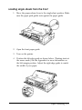
1
EPSON®
24-Pin Dot Matrix Printer
LQ-2070
All rights reserved. No part of this publication may be reproduced, stored in a retrieval
system, or transmitted in any form or by any means, electronic, mechanical, photocopying,
recording, or otherwise, without the prior written permission of Seiko Epson Corporation.
No patent liability is assumed with respect to the use of the information contained herein.
Neither is any liability assumed for damages resulting from the use of the information
contained herein.
Neither Seiko Epson Corporation nor its affiliates shall be liable to the purchaser of this
product or third parties for damages, losses, costs, or expenses incurred by purchaser or
third parties as a result of: accident, misuse, or abuse of this product or unauthorized
modifications, repairs, or alterations to this product.
Seiko Epson Corporation and its affiliates shall not be liable against any damages or
problems arising from the use of any options or any consumable products other than those
designated as Original EPSON Products or EPSON Approved Products by Seiko Epson
Corporation.
EPSON and EPSON ESC/P are registered trademarks and EPSON ESC /P 2 is a trademark
of Seiko Epson Corporation.
EPSON ConnectionSMis a service mark of Epson America, Inc.
General Notice: Other product names used herein are for identification purposes only and may be
trademarks of their respective companies.
Copyright © 1995 by Seiko Epson Corporation, Nagano, Japan.
User’s Guide
FCC Compliance Statement
For United States Users
This equipment has been tested and found to comply with the limits for a Class B digital
device, pursuant to Part 15 of the FCC Rules. These limits are designed to provide
reasonable protection against harmful interference in a residential installation. This
equipment generates, uses and can radiate radio frequency energy and, if not installed
and used in accordance with the instructions, may cause harmful interference to radio or
television reception. However, there is no guarantee that interference will not occur in a
particular installation. If this equipment does cause interference to radio and television
reception, which can be determined by turning the equipment off and on, the user is
encouraged to try to correct the interference by one or more of the following measures.
Reorient or relocate the receiving antenna
Increase the separation between the equipment and receiver
Connect the equipment into an outlet on a circuit different from that to which the
receiver is connected
Consult the dealer or an experienced radio/TV technician for help.
WARNING
The connection of a non-shielded equipment interface cable to this equipment will
invalidate the FCC Certification of this device and may cause interference levels which
exceed the limits established by the FCC for this equipment. It is the responsibility of the
user to obtain and use a shielded equipment interface cable with this device. If this
equipment has more than one interface connector, do not leave cables connected to
unused interfaces.
Changes or modifications not expressly approved by the manufacturer could void the
user’s authority to operate the equipment.
For Canadian Users
This Class B digital apparatus meets all requirements of the Canadian InterferenceCausing Equipment Regulations.
Cet appareil numerique de la classe B respecte toutes les exigences du Reglement sur le
materiel brouilleur du Canada.
ii
Declaration of Conformity
According to ISO/IEC Guide 22 and EN 45014
Manufacturer:
Address:
SEIKO EPSON CORPORATION
3-5, Owa 3-chome, Suwa-shi,
Nagano-ken 392 Japan
Representative:
Address:
EPSON EUROPE B.V.
Prof. J. H. Bavincklaan 5 1183 AT Amstelveen
The Netherlands
Declares that the Product:
Product Name:
Type Name:
Model:
Dot Matrix Printer
LQ-2070
P911A
Conforms to the following Directive(s) and Norm(s):
Directive 89/336/EEC:
EN 55022 Class B
EN 50082-1
IEC 801-2
IEC 801-3
IEC 801-4
Directive 73/23/EEC:
EN 60950
Directive 90/384/EEC:
EN 45501
April 1996
M. Hamamoto
President of EPSON EUROPE B.V.
iii
Energy Star Compliance
As an Energy Star Partner, EPSON has determined that this product
meets the Energy Star guidelines for energy efficiency.
The EPA estimates that if all desktop computers, printers, and other
peripheral devices met Energy Star standards, energy cost savings would
exceed $1 billion annually and carbon dioxide emissions would be
reduced by 20 million tons.
All of EPSON’s ink jet printers conform to Energy Star standards.
Note:
The Energy Star emblem does not represent EPA endorsement
service.
of any product or
Energy-saving Tips
Here are a few tips you can use to be even more energy-wise:
If your monitor isn’t Energy Star compliant, turn it off when you’re
not using it.
Turn off your computer, printer, and monitor each day when you are
done using them.
Use the print preview option in your software to catch errors before
you print a document.
If you have an electronic mail system available to you, send E-mail
rather than memos. Not only is this faster, but you’ll save paper and
storage space too.
Where to Get Help
If you purchased your printer in the United States or Canada, EPSON
provides customer support and service through a network of Authorized
EPSON Customer Care Centers. EPSON also provides the following
services when you dial (800) 922-8911:
Technical assistance with the installation, configuration, and
operation of EPSON products
Assistance in locating your nearest Authorized EPSON Reseller or
Customer Care Center
Customer relations
EPSON technical information library fax service
Product literature on current and new products
You can purchase ribbons, supplies, parts, printed manuals, and
accessories for your EPSON products from EPSON Accessories at (800)
873-7766 (U.S. sales only). In Canada, call (800) BUY-EPSON for sales
locations.
If you purchased your printer outside the United States or Canada,
contact your EPSON dealer or the marketing location nearest you for
customer support and service.
If you need help with any software program you are using, see that
program’s documentation for technical support information.
Electronic Support Services
If you have a modem, the fastest way to access helpful tips, specifications,
drivers, application notes, and bulletins for EPSON products is through
the online services below.
V
World Wide Web
If you are connected to the Internet and have a Web Browser, you can
access EPSON’s World Wide Web site at http://www.epson.com.
EPSON’s home page links users to What’s New, EPSON Products,
EPSON ConnectionsM, Corporate Info, and EPSON Contacts. Link to the
EPSON Connection for the latest drivers and FAQs (Frequently Asked
Questions) and the EPSON Chat area. To get in touch with EPSON
around the world, EPSON Contacts includes Contact Information for
local EPSON subsidiaries.
EPSON Bulletin Board Service
You can call the EPSON Bulletin Board Service (BBS) at (310) 782-4531.
No membership is required. Make sure your communications software is
set to 8 data bits with 1 stop bit, no parity bit, and a modem speed up to
28.8 Kbps. See the documentation that came with your communications
software for more information.
CompuServe@ online support
CompuServe members can call the EPSON America Forum on
CompuServe. If you are already a CompuServe member, simply type
GO EPSON at the menu prompt to reach the forum.
If you are not currently a member of CompuServe, you are eligible for
a free introductory membership as an owner of an EPSON product.
This membership entitles you to:
An introductory credit on CompuServe
Your own user ID and password
A complimentary subscription to CompuServe Magazine,
CompuServe’s monthly publication.
To take advantage of this offer, call (800) 848-8199 in the United States
and Canada and ask for representative #529. In other countries, call
(614) 529-1611 or your local CompuServe access number.
vi
For United Kingdom Users
Use of options
EPSON (UK) Limited shall not be liable against any damages or problems
arising from the use of any options or consumable products other than
those designated as Original EPSON Products or EPSON Approved
Products by EPSON (UK) Limited.
Safety information
warning:
This appliance must be earthed. Refer to rating plate for voltage and check that
the appliance voltage corresponds to the supply voltage.
Important:
The wires in the mains leadfitted to this appliance are coloured in accordance
with the following code:
Green and yellow - Earth
Blue - Neutral
Brown - Live
As the colours of the wires in the mains lead of this appliance may not
correspond with the coloured markings identifying the terminals in your
plug, proceed as follows:
The green and yellow wire must be connected to the terminal in the
plug which is marked with the letter E or with the earth symbol
or coloured green or green and yellow.
The blue wire must be connected to the terminal in the plug marked
with the letter N or coloured black.
The brown wire must be connected to the terminal in the plug
marked with the letter L or coloured red.
If damage occurs to the plug, replace the cord set or consult a qualified
electrician.
Replace fuses only with a fuse of the correct size and rating.
vii
Important Safety Instructions
Before using your printer, read the following safety instructions to use the
printer safely:
Turn off and unplug the printer before cleaning. Clean with a damp
cloth only. Do not spill liquid on the printer.
Do not place the printer on an unstable surface or near a radiator or
heat register.
Do not block or cover the openings in the printer’s cabinet. Do not
insert objects through the slots.
Use only the type of power source indicated on the printer’s label.
Connect all equipment to properly grounded power outlets. Avoid
using outlets on the same circuit as photocopiers or air control
systems that regularly switch on and off.
Do not let the power cord become damaged or frayed.
If you use an extension cord with the printer, make sure the total
ampere rating of the devices plugged into the extension cord does
not exceed the cords ampere rating. Also, make sure the total of all
devices plugged into the wall outlet does not exceed 15 amperes.
Except as specifically explained in this guide, do not attempt to
service the printer yourself.
Unplug the printer and refer servicing to qualified service personnel
under the following conditions:
If the power cord or plug is damaged; if liquid has entered the printer;
if the printer has been dropped or the cabinet damaged; or if the
printer does not operate normally or exhibits a distinct change in
performance.
Adjust only those controls that are covered by the operating
instructions.
viii
Contents
Introduction
Options
. . . . . . . . . . . . . . . . . . . . . . . . . . . . . . . . . .
HowtoUseThisManual . . . . . . . . . . . . . . . . . . . . . . . .
Warnings, Cautions, and Notes . . . . . . . . . . . . . . . . . . . .
Chapter 1
2
3
4
Setting Up the printer
Choosing a Place for the Printer . . . . . . . . . . . . . . . . . . . .
Unpacking the Printer . . . . . . . . . . . . . . . . . . . . . . . . .
Installing the Ribbon Cartridge . . . . . . . . . . . . . . . . . . . .
Plugging in the Printer . . . . . . . . . . . . . . . . . . . . . . . . .
Running the Self Test . . . . . . . . . . . . . . . . . . . . . . . . . .
Connecting the Printer to Your Computer . . . . . . . . . . . . . .
Installing the Printer Driver . . . . . . . . . . . . . . . . . . . . . .
For Microsoft Windows Users . . . . . . . . . . . . . . . . . .
For DOS program users . . . . . . . . . . . . . . . . . . . . . .
DOS printer utilities . . . . . . . . . . . . . . . . . . . . . . . .
1-2
1-4
1-5
1-10
1-11
1-14
1-15
1-15
1-21
1-21
ix
Chapter 2
Paper Handling
Setting the paper release lever . . . . . . . . . . . . . . . . . . . . .
Using Single Sheets . . . . . . . . . . . . . . . . . . . . . . . . . . .
Loading single sheets with the paper guide . . . . . . . . . .
Loading single sheets from the front . . . . . . . . . . . . . .
Using Continuous Paper . . . . . . . . . . . . . . . . . . . . . . . .
Loading paper with the rear push tractor . . . . . . . . . . .
Loading paper with the optional tractor unit . . . . . . . . .
Loading paper with the push/pull tractor combination . . .
Removing paper from the tractor . . . . . . . . . . . . . . . .
Switching Between Continuous Paper and Single Sheets . . . . .
Switching to single sheets . . . . . . . . . . . . . . . . . . . .
Switching to continuous paper . . . . . . . . . . . . . . . . .
Printing on Special Paper . . . . . . . . . . . . . . . . . . . . . . .
Adjusting the paper thickness lever . . . . . . . . . . . . . .
Multipart forms . . . . . . . . . . . . . . . . . . . . . . . . . .
Labels . . . . . . . . . . . . . . . . . . . . . . . . . . . . . . . .
Envelopes . . . . . . . . . . . . . . . . . . . . . . . . . . . . .
Postcards . . . . . . . . . . . . . . . . . . . . . . . . . . . . . .
Roll paper . . . . . . . . . . . . . . . . . . . . . . . . . . . . .
Chapter 3
Using the Printer
Control Panel . . . . . . . . . . . . . . . . . . . . . . . . . . . . . .
Lights
. . . . . . . . . . . . . . . . . . . . . . . . . . . . . .
Buttons . . . . . . . . . . . . . . . . . . . . . . . . . . . . . . .
Other control panel features . . . . . . . . . . . . . . . . . . .
Using the Default Setting Mode . . . . . . . . . . . . . . . . . . . .
Selecting an instruction sheet language . . . . . . . . . . . .
Changing the default settings . . . . . . . . . . . . . . . . . .
Printer functions . . . . . . . . . . . . . . . . . . . . . . . . . .
Using Quiet Mode . . . . . . . . . . . . . . . . . . . . . . . . . . .
Using Micro Adjust . . . . . . . . . . . . . . . . . . . . . . . . . . .
Using the Tear-Off Function . . . . . . . . . . . . . . . . . . . . . .
Using auto tear-off mode . . . . . . . . . . . . . . . . . . . . .
Using the Tear Off/Bin button . . . . . . . . . . . . . . . . .
Using Bid Adjustment . . . . . . . . . . . . . . . . . . . . . . . . .
Printing Barcodes . . . . . . . . . . . . . . . . . . . . . . . . . . . .
x
2-2
2-4
2-4
2-7
2-9
2-9
2-13
2-27
2-30
2-30
2-31
2-32
2-32
2-33
2-34
2-35
2-36
2-36
2-36
3-2
3-2
3-4
3-6
3-7
3-7
3-7
3-9
3-13
3-13
3-15
3-16
3-17
3-18
3-18
Chapter 4
Using Printer Options
Cut-Sheet Feeders . . . . . . . . . . . . . . . . . . . . . . . . . . . . 4-2
Installing the high capacity cut-sheet feeder . . . . . . . . . . 4-2
Loading paper with the high capacity cut-sheet feeder . . . . 4-4
Installing the double bin cut-sheet feeder . . . . . . . . . . . 4-6
Switching between continuous paper and the cut-sheet feeder 4-7
Selecting single-sheets, postcards, or envelopes . . . . . . . . 4-8
Pull Tractor . . . . . . . . . . . . . . . . . . . . . . . . . . . . . . . . 4-9
Roll Paper Holder . . . . . . . . . . . . . . . . . . . . . . . . . . . . 4-9
Interface Cards . . . . . . . . . . . . . . . . . . . . . . . . . . . . . . 4-12
Installing an interface card . . . . . . . . . . . . . . . . . . . . 4-12
The C82305* and C82306* serial interface cards . . . . . . . 4-14
Chapter 5
Maintenance and Transportation
Cleaning the Printer . . . . . . . . . . . . . . . . . . . . . . . . . . .
Replacing the Ribbon . . . . . . . . . . . . . . . . . . . . . . . . . .
Transporting the Printer . . . . . . . . . . . . . . . . . . . . . . . .
Chapter
5-2
5-3
5-4
6 Troubleshooting
Power Supply . . . . . . . . . . . . . . . . . . . . . . . . . . . . . .
Power is not being supplied . . . . . . . . . . . . . . . . . . .
Printing . . . . . . . . . . . . . . . . . . . . . . . . . . . . . . . . . .
The printer does not print . . . . . . . . . . . . . . . . . . . .
The print is faint or uneven . . . . . . . . . . . . . . . . . . .
Dots are missing in printed characters or graphics . . . . . .
Printed characters are not what you expect . . . . . . . . . .
The print position is not what you expect . . . . . . . . . . .
Paper Handling . . . . . . . . . . . . . . . . . . . . . . . . . . . . .
Single sheets do not feed properly . . . . . . . . . . . . . . . .
Continuous paper does not feed properly . . . . . . . . . . .
Options . . . . . . . . . . . . . . . . . . . . . . . . . . . . . . . . . .
The paper does not feed properly with the cut-sheet feeder .
Continuous paper does not feed properly when using
the tractors in a push/pull position . . . . . . . . . . . . . .
6-2
6-2
6-3
6-3
6-5
6-5
6-6
6-6
6-7
6-7
6-8
6-9
6-9
6-11
xi
Appendix Specifications, Command Summary, and
Character Tab/es
Printer Specifications . . . . . . . . . . . . . . . . . . . . . . . . . .
Printing . . . . . . . . . . . . . . . . . . . . . . . . . . . . . . .
Paper . . . . . . . . . . . . . . . . . . . . . . . . . . . . . . . .
Paper alignment . . . . . . . . . . . . . . . . . . . . . . . . . .
Printable area . . . . . . . . . . . . . . . . . . . . . . . . . . .
Mechanical . . . . . . . . . . . . . . . . . . . . . . . . . . . . .
Electrical . . . . . . . . . . . . . . . . . . . . . . . . . . . . . .
Environmental . . . . . . . . . . . . . . . . . . . . . . . . . . .
Safety approvals . . . . . . . . . . . . . . . . . . . . . . . . . .
CE marking . . . . . . . . . . . . . . . . . . . . . . . . . . . .
Interface specifications . . . . . . . . . . . . . . . . . . . . . .
Using Commands . . . . . . . . . . . . . . . . . . . . . . . . . . . .
Sending printer commands . . . . . . . . . . . . . . . . . . .
Using the command summary . . . . . . . . . . . . . . . . .
Commands Arranged by Topic . . . . . . . . . . . . . . . . . . . .
General operation . . . . . . . . . . . . . . . . . . . . . . . . .
Paper feeding . . . . . . . . . . . . . . . . . . . . . . . . . . .
Page format . . . . . . . . . . . . . . . . . . . . . . . . . . . .
Print position motion . . . . . . . . . . . . . . . . . . . . . . .
Font selection . . . . . . . . . . . . . . . . . . . . . . . . . . .
Font enhancement. . . . . . . . . . . . . . . . . . . . . . . . .
Character handling . . . . . . . . . . . . . . . . . . . . . . . .
Spacing.. . . . . . . . . . . . . . . . . . . . . . . . . . . . . .
Graphics . . . . . . . . . . . . . . . . . . . . . . . . . . . . . .
Bit image . . . . . . . . . . . . . . . . . . . . . . . . . . . . . .
Barcode . . . . . . . . . . . . . . . . . . . . . . . . . . . . . . .
Character Tables . . . . . . . . . . . . . . . . . . . . . . . . . . . .
International Character Sets . . . . . . . . . . . . . . . . . . .
Graphics Character Tables . . . . . . . . . . . . . . . . . . . .
Glossary
Index
xii
A-2
A-2
A-4
A-7
A-8
A-9
A-10
A-11
A-11
A-12
A-12
A-17
A-17
A-17
A-18
A-18
A-18
A-19
A-20
A-21
A-23
A-24
A-27
A-27
A-28
A-29
A-32
A-32
A-32
Introduction
Your new EPSON® 24-pin dot matrix printer offers high
performance with a wide range of features in a compact design.
You will find the same high-quality printing and ease of operation
you have come to expect from EPSON printers, including:
High speed draft mode printing of up to 300 characters per
second (cps) at 10 characters per inch (cpi)
Easy paper handling for both single sheets and continuous
paper
Eight barcode fonts and four scalable fonts, as well as one
draft and nine letter quality bit-map fonts
Multipart forms printing of one original plus up to three
copies
A convenient control panel that allows direct selection of fonts
Support of advanced EPSON ESC/P2™ commands and IBM@
2390/2391 Plus emulation
Large printable area; 68 lines with A4 size paper and 63 lines
with letter size paper
Software utilities, including a printer driver and a remote
control panel utility that let you change printer settings
quickly and easily.
Introduction
1
Options
The following options are available for your printer:
Cut-sheet feeder (High capacity, C80673*; Second bin,
C80674*), automatically feeds up to 150 sheets of paper or 25
envelopes (high capacity) without reloading. You can create a
double bin cut-sheet feeder by combining the high capacity
and second bin feeders. In this way you can preload up to 200
A4 or letter size sheets of paper, and you can use two different
sizes.
Pull tractor unit (C80032*), provides easy paper handling,
which is useful for printing on multipart forms. You can also
use this tractor as a front push tractor.
Roll paper holder (#8310), allows you to use your printer with
8.5-inch roll paper like that used with telex machines.
Interface cards, available to supplement the printer’s built-in
parallel interface.
2 Introduction
How to Use This Manual
This manual provides illustrated, step-by-step instructions for
setting up and operating your printer.
Chapter 1 contains information on unpacking, setting up, testing,
and connecting the printer. Be sure to read this chapter first.
Chapter 2 explains how to load and use single sheets, continuous
paper, and special paper in the printer.
Chapter 3 describes the basic operation of your printer.
Chapter 4 explains how to use optional accessories with your
printer.
Chapter 5 provides maintenance information, including
transportation guidelines.
Chapter 6 contains troubleshooting tips. If the printer does not
operate properly or the printed results are not what you expect,
see this chapter for a list of problems and solutions.
The appendix lists the printer’s specifications, commands, and
character tables.
At the end of the manual you’ll find a glossary and an index.
Introduction
3
Warnings, Cautions, and Notes
This guide uses the following conventions:
Warnings must be followed to avoid bodily injury.
Cautions must be observed to avoid damage to your equipment.
Notes contain important information and useful tips on the operation
of your printer.
4 Introduction
Chapter 1
Setting Up the Printer
Choosing a Place for the Printer . . . . . . . . . . . . . . . . . . . . 1-2
Unpacking the Printer
. . . . . . . . . . . . . . . . . . . . . . . . .
1-4
Installing the Ribbon Cartridge . . . . . . . . . . . . . . . . . . . . 1-5
Plugging in the Printer . . . . . . . . . . . . . . . . . . . . . . . . .
1-10
Running the Self Test . . . . . . . . . . . . . . . . . . . . . . . . . .
1-11
Connecting the Printer to Your Computer . . . . . . . . . . . . . . 1-14
Installing the Printer Driver . . .
For Microsoft Windows Users .
For DOS program users . . . .
DOS printer utilities . . . . . .
.
.
.
.
.
.
.
.
.
.
.
.
.
.
.
.
.
.
.
.
.
.
.
.
.
.
.
.
.
.
.
.
.
.
.
.
.
.
.
.
.
.
.
.
.
.
.
.
.
.
.
.
.
.
.
.
.
.
.
.
.
.
.
.
.
.
.
.
.
.
.
.
. 1-15
. 1-15
. 1-21
. 1-21
Setting Up the Printer
1-1
This chapter explains how to set up the printer and install the
printer driver software.
Choosing a Place for the Printer
When selecting a place to set up your printer, be sure to follow
these guidelines:
Place the printer on a flat, stable surface, close enough to
the computer for the interface cable to reach it.
Leave adequate room around the printer for easy operation
and maintenance.
Avoid locations that are subject to direct sunlight, excessive
heat, moisture, or dust.
Use a properly grounded electrical outlet; do not use an
adapter plug.
Place the printer where you can easily unplug the power
cord.
Avoid electrical outlets controlled by wall switches or
automatic timers. An interruption of power can erase
information in the memory of your printer or computer.
Avoid outlets on the same circuit as large motors or other
appliances that can cause voltage fluctuations.
Keep the entire computer system away from potential
sources of electromagnetic interference, such as
loudspeakers or the base units of cordless telephones.
1-2
Setting Up the Printer
If you plan to use a printer stand, follow these guidelines:
Use a stand that supports at least 26 kg (57.8 lbs).
Never use a stand that tilts the printer at an angle of more
than 15 degrees from horizontal. If you install a cut-sheet
feeder, the stand must keep your printer level.
If you plan to load continuous paper through the bottom of
the printer, choose a stand that provides an unobstructed
paper path.
Position your printer’s power cord and interface cable so
they do not interfere with paper feeding. If possible, secure
the cables to a leg of the printer stand.
Align the paper stack so that the paper feeds straight into
the tractor’s sprocket units.
Setting Up the Printer
1-3
Unpacking the Printer
In addition to this guide, your printer box should include an
EPSON printer driver disk, Notice Sheet, and the following items:
Note:
Depending on your printer model, the power cord may be permanently
attached to the printer.
You must remove all protective materials packed around and
inside your printer before you set it up and turn on the power.
Follow the directions on the Notice Sheet (packed with the printer)
to remove these materials. A screwdriver has been included for
removing the transportation screw.
1-4
Setting Up the Printer
Save all packing and protective materials, including the protective
locking clips on the paper tension unit and the transportation
screw, in case you need to ship the printer in the future. It should
always be transported in its original packaging.
Caution:
There are several versions of the printer designed for different
voltages, and it is not possible to adjust the printer for use at
another voltage. If the label on the back of the printer does not
show the correct voltage for your country, contact your dealer.
Installing the Ribbon Cartridge
before installing the ribbon cartridge, make sure that the power
cord is not plugged into an electrical outlet.
1.
Lift the printer cover up and off.
Setting Up the Printer
1-5
2.
Make sure the print head is at the ribbon installation position as
shown below. If the print head is not at this position, slide the
print head to the correct position (the indented portion of the
paper tension unit).
Warning
Never move the printhead while the printer is turned on; this can
damage the printer. Also, the print head may become hot during
use. Always let it cool before you touch it.
3.
1-6
Remove the ribbon cartridge from its packaging. Then remove
the plastic separator from the middle of the ribbon cartridge
and discard the separator.
Setting Up the Printer
4.
Hold the cartridge so that the ribbon-tightening knob is facing
up and is on the left. Place the bottom edge of the cartridge
into the printer so that the notch on each end of the cartridge
fits over the small peg on each side of the printer.
5.
Lay the cartridge flat and press gently until it clicks into place
on both ends.
6.
Lift the ribbon guide and insert it firmly over the metal pins
behind the print head. Press down on the guide until it clicks
into place. Make sure the ribbon is not twisted or creased and
that it is in place behind the print head. Turn the
ribbon-tightening knob to remove any slack in the ribbon.
Setting Up the Printer
1-7
1-8
7.
Slide the print head from side to side to make sure it moves
smoothly.
8.
Replace the printer cover by first inserting the front tabs into the
slots near the front of the printer; then lower it until it locks
into place.
Setting Up the Printer
9.
Insert the paper separator into the paper guide as shown below.
Note:
You may find it easy to insert the paper separator one side at a time.
You need not separate the paper guide and the paper separator, in
case you need to ship the printer.
10. Attach the paper guide by sliding the slots on the bottom of the
paper guide over the pegs behind the paper tension unit.
Setting Up the Printer
1-9
11. Lift the paper path guide, and rest it against the paper guide.
Note:
Always close the printer cover before printing. The printer stops printing
when the cover is open.
Plugging in the Printer
1.
Make sure the printer is turned off.
2.
Check the label on the back of the printer to make sure the
voltage matches that of your electrical outlet.
Caution:
If the rated voltage and your outlet voltage do not match,
contact your dealer for assistance. Do not plug in the power
cord.
3.
If the power cord is not attached to the printer, connect the
appropriate end to the AC inlet on the printer’s rear panel.
4.
Plug the power cord into a properly grounded electrical outlet.
Before continuing, test the printer to make sure it is functioning
properly as described in the next section.
1-10
Setting Up the Printer
Running the Self Test
You can run a self test on the printer in letter quality or draft
mode, with either continuous paper or single sheets. You can load
the paper from the rear, front, top, or bottom. The following steps
describe how to run the test on single-sheet paper, loaded from
the top. See Chapter 2 for more information on paper handling.
The printer prints the self test in the currently selected font.
1.
Make sure the printer is turned off and the paper path guide is
open.
2.
Move the paper release lever to the single-sheet position.
3.
For a letter quality test, hold down the Load/Eject button
while you turn on the printer. For a draft printing test, hold
down the LF/FF button while you turn on the printer.
Setting Up the Printer
1-11
Move the left edge guide until it locks in place next to the arrow
guide mark. Then adjust the right edge guide to match the
width of your paper.
4.
Caution:
Run the self test using paper at least 360 mm (14 inches)
wide; otherwise, the print head prints directly on the platen.
5.
1-12
Lift the paper path guide, and rest it against the paper guide.
Setting Up the Printer
6.
Insert a sheet of paper between the edge guides until it meets
resistance. Make sure you adjust the edge guides to match the
width of your paper. After a few seconds, the printer feeds the
paper to the loading position and begins printing the self test.
Note:
Always close the printer cover before printing. The printer stops
printing when the cover is open.
If you want to temporarily stop printing the self test, press the
Pause button. To resume printing, press Pause again.
7. To end the self test, first press the Pause button. If paper
remains in the printer, press the Load/Eject button to eject
the page; then turn off the printer. Here is part of a typical self
test:
Setting Up the Printer
Z-13
Connecting the Printer to Your Computer
Use an interface cable with a 36-pin connector on the printer end,
and a connector that will work with your computer on the other
end. See your computer’s reference guide for the required
connector type. Follow these steps to connect the printer to your
computer:
1.
Make sure both the printer and computer are turned off.
2.
Plug the cable connector securely into the printer’s parallel
interface connector. Squeeze the wire clips together until they
lock in place on both sides of the connector.
Note:
If your cable has a ground wire, connect it to the ground connector
beneath the interface connector.
3.
1-14
Plug the other end of the cable into the computer. (If there is a
ground wire at the computer end of the cable, attach it to the
ground connector at the back of the computer.)
Setting Up the Printer
Installing the Printer Driver
The EPSON printer driver is software that helps you take full
advantage of your printer’s capabilities.
The EPSON printer driver disk that came with your printer
includes the driver software as well as two utilities to help you
control the printer through DOS.
For Microsoft Windows Users
Before you install the driver, make a backup copy of your driver
disk. If you are running Windows 3.1, follow the steps in the next
section to install the printer driver. If you are running Windows
95, see page 1-16 for instructions.
Install the driver for Windows 3.1 users
Follow these steps to install the printer driver for Windows 3.1:
1.
Make sure Windows is running.
2.
Insert the EPSON driver disk into drive A (or B, depending on
your computer).
3.
From the File menu, choose Run.
4.
Type A: SETUP (or B: SETUP); then click OK.
5.
Select LQ-2070 ESC/P 2 as the Printer Model and click
Continue. The printer driver is installed automatically.
6.
Click OK.
The LQ-2070 printer driver is now installed on your computer.
Windows will now use the LQ-2070 as the default printer.
If you need to change the default printer or port assignment, use
the Printers utility in the Control Panel group.
Setting Up the Printer
1-15
Installing the driver for Windows 95 users
Follow these steps to install the printer driver using the Windows
95 plug-and play capabilities:
Note:
To install the driver using the Windows 95 plug-and play capabilities,
your computer’s parallel port must be an IEEE-1284 (ECP orEPP
compatible) bidirectional parallel port. See your computer documentation
for more information.
1.
Make sure plain paper is loaded in the printer and the printer is
connected to the computer’s parallel port. (The paper is used
to perform a test print in step 11.)
2.
Turn off your printer and computer, if necessary.
3.
Turn on the printer first; then turn on the computer. Your
computer begins loading Windows 95.
4.
If you defined a password, enter it at the prompt. You see the
New Hardware Found screen.
Note:
If you do not see the New Hardware Found screen, pleasefollow the
procedure under “Installing the driver while running Window TE 95”
on page 1-18 instead.
5.
Make sure your printer model name is displayed on the screen.
Then click the Driver from disk provided by hardware
manufacturer button. Do not select any of the other buttons.
Note:
The next time you turn on your computer after installing the driver,
Windows 95 may display the New Hardware Found screen again.
In this case, click the Do not install a driver radio button; then
click OK. This screen does not appear again.
1-16
Setting Up the Printer
6.
Click OK. You see the Install From Disk screen.
7.
Insert the Windows printer driver disk in a disk drive.
8.
If you inserted the disk in drive A, click OK. Otherwise, change
the drive letter in the Copy manufacturer’s files from box and
click OK.
9.
At the next screen you can type a unique name for the printer in
the Printer name box. We recommend that you keep the
model name as shown. The program will copy the files to your
hard disk and add an icon to the Printers folder using the
printer name you assign.
To use the printer as the default printer for Windows 95
applications, select Yes. (NO is the default setting.)
10. Click the Next button.
11. In the next screen, select YES to print a test page.
12. Click the Finish button.
13. Choose Yes in the test page confirmation dialog if the page
printed correctly. If it did not print correctly, choose NO and
follow the directions on the screen.
To access the driver, see “Checking the printer driver settings,”
page 1-19.
Setting Up the Printer
1-17
Installing the driver while running Windows 95
Follow these steps to install the printer driver for Windows 95.
1.
In the Desktop window, double-click the My Computer icon.
2.
Double-click the Printers folder.
3.
Double-click the Add Printer icon.
4.
Click the Next button.
5.
Select the Local printer or Network printer radio button.
6.
Click the Next button.
7.
Click the Have Disk button.
8.
Insert the floppy disk containing the driver into your computer’s
floppy disk drive.
9.
Type A: WIN95 (or B: WIN95); then click OK.
10. Select the port you want to use with this printer.
11. Click the Next button.
12. Select the Yes or NO radio button to make the default printer
setting.
13. Click the Next button.
14. Click the Yes radio button to print a test page.
15. Click Finish.
16. In the dialog box that appears, choose Yes if the test page
printed satisfactorily. If it didn’t print satisfactorily, choose
NO and follow the directions that appear on your screen.
1-18
Setting Up the Printer
Checking the printer driver settings
Before you start printing, you should make sure that the driver
settings match your document requirements. While many
Windows applications override the printer settings made with the
driver, some do not.
Be sure to check the following:
Resolution
The printing resolution in dots per
inch (dpi).
Paper size
The size of the paper loaded in the
printer.
Orientation
The direction of printing on the page
(portrait or landscape).
Paper source
Tractor, manual feed, or sheet feeder.
For Windows 3.1 users
Follow these steps to select the appropriate settings:
1.
In the Main window, double-click the Control Panel icon.
2.
Double-click the Printers icon.
3.
Make sure your printer is highlighted, and click the Setup
button in the Print Setup menu.
4.
Select the paper size you have loaded in the printer from the
Paper Size list. If you don’t see your paper size in the list, use
the arrows on the right to scroll through the list. The diagram
on the screen changes according to the paper size you select.
5.
Select Portrait or Landscape orientation. The diagram on the
screen changes according to the orientation you select.
6.
Select the resolution you desire.
Setting Up the Printer
1-19
7.
Select the paper source.
8.
Click Options to open the option menu.
You can control intensity by clicking the arrow to darker or
lighter. You can control dithering by choosing None, Coarse,
Fine, or
Line Art.
For Windows 95 users
Follow these steps to select the appropriate settings:
1-20
1.
In the Desktop window, click the Start button.
2.
Select Settings; then click Printers.
3.
Right-click on your printer icon.
4.
Open the Printer menu, and choose Properties.
5.
Click on the Paper tab, and select the paper size you have loaded
in the printer from the Paper size list. If you don’t see your
paper size, scroll through the list, and select the correct size.
The diagram on the screen changes according to the paper size
you select.
6.
Select Portrait or Landscape orientation. The diagram on the
screen changes according to the orientation you select.
7.
Select the paper source.
8.
Select the resolution you desire on the Graphics menu.
9.
Make any other settings you wish, and click OK when you are
finished.
Setting Up the Printer
For DOS program users
Most DOS software programs include drivers for EPSON ESC/P2
printers. Also, DOS programs require you to select from a list of
printers to install the printer driver. If the LQ-2070 is not included
in the list, contact your software manufacturer to see if there is an
updated driver available or select the first printer available from
the list below.
LQ-2170
LQ-1070/1070+
LQ-870/1170
LQ-850+/1050+
LQ-850/1050
LQ-510/550/1010
LQ-200
LQ-500
LQ-860+/1060+
LQ-2550
LQ-2500
LQ-800/1000
LQ-1500
See your DOS program’s documentation for instructions on
selecting the printer driver.
DOS printer utilities
Your printer comes with the EPSON Remote! and EPSON
Calibration utilities. You can use EPSON Remote! to make setting
changes from your computer instead of using the printer’s control
panel. Also, you can use EPSON Calibration to properly align
your printout.
Setting Up the Printer
1-21
Chapter 2
Paper Handling
Setting the paper release lever . . . . . . . . . . . . . . . . . . . . . 2-2
Using Single Sheets . . . . . . . . . . . . . . . . . . . . . . . . . . . 2-4
Loading single sheets with the paper guide . . . . . . . . . . . . 2-4
Loading single sheets from the front . . . . . . . . . . . . . . . . 2-7
Using Continuous Paper . . . . . . . . . . . . . . . . . . . . . . . .
Loading paper with the rear push tractor . . . . . . . . . . . . .
Loading paper with the optional tractor unit . . . . . . . . . . .
Loading paper with the push/pull tractor combination . . . . .
Removing paper from the tractor . . . . . . . . . . . . . . . . . .
2-9
2-9
2-13
2-27
2-30
Switching between Continuous Paper and Single Sheets . . . . . . 2-30
Switching to single sheets . . . . . . . . . . . . . . . . . . . . . . 2-31
Switching to continuous paper . . . . . . . . . . . . . . . . . . . 2-32
Printing on Special Paper . . . . . . . . . . .
Adjusting the paper thickness lever . . .
Multipart forms . . . . . . . . . . . . . . .
Labels . . . . . . . . . . . . . . . . . . . . .
Envelopes . . . . . . . . . . . . . . . . . .
Postcards . . . . . . . . . . . . . . . . . . .
Roll paper . . . . . . . . . . . . . . . . . .
. . . . . . . . . . . . 2-32
.
.
.
.
.
.
.
.
.
.
.
.
.
.
.
.
.
.
.
.
.
.
.
.
.
.
.
.
.
.
.
.
.
.
.
.
.
.
.
.
.
.
.
.
.
.
.
.
.
.
.
.
.
.
.
.
.
.
.
.
.
.
.
.
.
.
.
.
.
.
.
.
2-33
2-34
2-35
2-36
2-36
2-36
Paper Handling 2-1
This chapter describes how to:
Set the paper release lever
Load single sheets
Load continuous paper with the rear tractor or the
optional tractor(s)
Switch between paper-feed methods
Print on special paper.
Setting the paper release lever
Before you load paper, you must to set the paper release lever for
the type of paper and feed method you want to use. The paper
release lever has four positions, with icons indicating the type of
paper and paper path for each position.
2-2 Paper Handling
Paper release
lever position
Tractor position and purpose
Single-sheet position-for loading all single sheets
(including envelopes and postcards). whether from
the front, rear, optional cut-sheet feeders, or roll
paper holder.
Rear push and rear push/pull tractor
combination-for loading continuous paper from
the rear.
Front push and front push/pull tractor
combination--for continuous paper from
the front.
Pull tractor position-for loading continuous paper
from the front, rear, or bottom.
Note:
Although some arrows show paper loading from the top, the
paper actually enters the printer from the rear, even when using
the paper guide.
The push/pull tractor combination is recommended for enhanced
paper handling when using continuous paper. See page 2-13 for
more details.
For detailed information about printing on single sheets, see the
next section. For detailed information about printing on
continuous paper and using an optional tractor, see “Using
Continuous Paper,” page 2-9.
Paper Handling
2-3
Using Single Sheets
You can print on single sheets of paper from 101 to 420 mm (4.0 to
16.5 inches) wide. You can load single sheets from either the top or
front of the printer.
Loading single sheets with the paper guide
1.
Move the paper release lever to the single-sheet position. Make sure
the paper guide is installed and the paper path guide is open.
2
2.
2-4
Turn on the printer.
Paper
Handling
3.
Slide the left edge guide until it stops next to the arrow on the
paper guide. Then adjust the right edge guide to match the
width of your paper.
4.
Lift the paper path guide and rest it against the paper guide.
Paper Handling
2-5
5.
Insert the paper firmly between the edge guides until it meets
resistance. After a few seconds, the printer advances the paper
to the loading position. You are now ready to print.
Caution:
Do not use the knob on the right side of the printer except to clear
paper jams when the printer is turned of. Otherwise, you may
damage the printer or cause it to lose the top-of-form position.
If the platen turns but the printer doesn’t load the paper,
completely remove the paper and re-insert it.
To eject the paper, press the Load/Eject button.
2-6
Paper
Handling
Loading single sheets from the front
1.
Move the paper release lever to the single-sheet position. Make
sure the paper path guide rests against the paper guide.
2.
Open the front paper guide.
3.
Turn on the printer.
4.
Position the left edge guide as shown below. (Printing starts at
the arrow mark.) See the Appendix for more information on
the left margin position. Adjust the right edge guide to match
the width of your paper.
Paper Handling 2-7
5.
Insert the paper until it meets resistance. After a few seconds, the
printer loads the paper to the loading position. You are now
ready to print.
2
Caution:
Do not use the knob on the right side of the printer except to clear
paper jams when the printer i s turned off. Otherwise, you may
damage the printer or cause it to lose the top-of-form position.
If the platen turns but the printer doesn’t load the paper,
completely remove the paper and re-insert it more firmly.
To eject the paper, press the Load/Eject button.
2-8 Paper Handling
Using Continuous Paper
The printer’s built-in paper-handling system allows you to load
continuous paper using the standard rear push tractor.
In addition to this, you can load continuous paper through the
front or bottom using one or more optional tractor units. For more
information on using the optional tractor unit, see “Loading paper
with the optional tractor unit” on page 2-13.
You can print on continuous paper that is 101 to 406 mm
(4 to 16 inches) wide.
Note:
The standard rear push tractor cannot be removed.
Caution:
Do not load labels through the rear tractor unit. Labels can come
off the paper and cause damage. Load labels only through the
front or bottom.
Loading paper with the rear push tractor
You can use the rear push tractor to load ordinary continuous
paper and multi-part forms but not labels. To load labels, see
“Loading paper with the optional tractor unit” on page 2-13.
Make sure you align your paper supply with the paper path so the
paper feeds smoothly into the printer. Also, make sure the ejected
paper does not interfere with the paper about to load.
Using the optional pull tractor with the rear push tractor may help
prevent paper jams. For more information about using the
optional tractor unit, refer to “Loading paper with the optional
tractor unit” on page 2-13.
Paper Handling 2-9
Follow the steps below to load paper with the rear push tractor:
1.
Make sure the printer is turned off.
2.
Remove the printer cover and paper guide.
3.
Make sure the paper release lever is set to the rear push tractor
position.
2
4.
Release the sprockets by pushing the sprocket locks forward.
2
2-10 Paper Handling
5.
Slide the left sprocket to the left margin of the paper using the
scale on the printer as shown below. (Printing starts at the “0”
mark. See the Appendix for more information on the left
margin position.) Then slide the right sprocket to match the
width of your paper, but do not lock it. Also, move the paper
support midway between the sprocket units.
6.
Make sure your paper has a clean, straight edge. Then open the
sprocket covers and fit the holes of the paper over the tractor
pins.
Paper Handling 2-11
7.
Close the sprocket covers.
8.
Slide the right sprocket to remove any slack in the paper; then
lock it in place.
9.
Attach the printer cover and paper guide.
10. Slide the left and right edge guides to the center of the paper
exit path for smoother paper feeding.
11. Turn on the printer. When the printer receives data, it
automatically loads the paper before printing.
Note:
Always close the printer cover before printing. The printer stops
printing when the cover is open.
You can also advance the paper to the loading position by
pressing the Load/Eject button.
As you print, make sure the paper advances behind the printer
guide as shown below. Make sure the paper path guide rests
against the paper guide.
2.
Caution:
Do not use the knob on the right side of the printer except to clear
paper jams when the printer is turned off. Otherwise, you may
damage the printer or cause it to lose the top-of-form position.
2-12 Paper Handling
Loading paper with the optional tractor unit
The printer’s paper handling system allows you to load
continuous paper through the front or bottom in addition to the
rear, if you purchase the optional pull tractor unit:
Selecting the tractor position and paper path
The table below lists the different ways to feed continuous paper.
Always set the paper release lever to the position indicated for the
paper feed method you are using.
Note:
The push/pull tractor combination is recommended for enhanced
paper handling.
The rear push tractor cannot be removed, but it is deactivated in
some paper release lever positions
Make sure you align your paper supply with the paper loaded in
the tractor so the paper feeds smoothly into the printer.
Paper Handling 2-13
If you feed paper through the bottom paper slot, use a printer
stand that has a large enough opening for paper to feed from the
bottom without obstruction.
Changing tractor positions
You can use the optional pull tractor unit as either a front push
tractor or a pull tractor; you just change the tractor position
according to your paper feeding method.
Installing the tractor in the front push position
Before you can load continuous paper from the front tractor
position, you must first purchase the optional pull tractor unit.
You can use the optional pull tractor unit as a front push tractor.
Follow the instructions below to install it.
1.
Make sure the printer is turned off.
2.
Open the front paper guide and remove it by grasping the fins
on both sides and pulling it straight out of the printer.
2-
Note:
When loading multipart forms that are bound on only one side by
line gluing, always use the rear push tractor. This type of form
cannot be fed from the front push tractor.
2-14
Paper Handling
3.
Push the tractor into the printer’s mounting slots as shown
below.
You are now ready to load continuous paper with the front push
tractor. See “Loading paper with the front push tractor” on page
2-21 or “Loading paper with the push/pull tractor combination”
on page 2-27 for instructions.
Removing the tractor from the front push position
If you want to use the tractor in another position, follow the
directions below to remove it. Then see the appropriate section for
installation instructions.
1.
Make sure the printer is turned off.
2.
Remove any paper that is in the feed path.
Paper Handling
2-15
3.
Open the front paper guide and remove it by grasping both sides
and pulling it straight out of the printer.
2-
4.
Press the tractor’s lock tabs, tilt it up, and lift it out of the printer.
2-
2-16 Paper Handling
5. Replace the front paper guide by sliding it along the track until
it locks in place.
6.
Close the front paper guide.
lnstalling the tractor in the pull posifion
Before you load continuous paper using the pull tractor position,
you must first purchase the optional pull tractor.
1.
Make sure the printer is turned off.
2.
Lift the printer cover and paper guide up and off the printer.
Paper Hand 1 ing
2-17
3.
Press the tabs on both ends of the clear plastic paper-tension
unit, raise the front of the unit, and lift it off the printer.
2-:
4. Place the tractor’s tabs into the printer’s mounting slots, then
press the tractor back until it locks into place.
2-1
Note:
Check the paper thickness lever position to ensure that it wasn’t
moved during pull tractor installation. See “Adjusting the paper
thickness lever” on page 2-33 for the correct lever position.
2-18 Paper Handling
5.
Replace the paper guide.
You are now ready to load continuous paper with the pull tractor.
See “Loading paper with the pull tractor” on page 2-24 or
“Loading paper with the push/pull tractor combination” on page
2-27 for more details.
Removing the tractor from the pull position
If you want to use the tractor in another position, follow the
directions below to remove it. Then see the appropriate section for
installation instructions.
1.
Make sure the printer is turned off.
2.
Remove any paper that is in the feed path.
3.
Remove the printer cover and paper guide.
4.
Hold down the tractor’s lock tabs, tilt it forward, and lift it off
the printer.
Paper Handling
2-19
5.
Replace the clear plastic paper-tension unit by placing the small
pegs into the notches on each side of the printer. Press down
until it locks into place.
2-
6.
Slide the print head back and forth to make sure it can move
freely. If it cannot, the paper-tension unit was incorrectly
installed. Remove it and install it again.
Warning:
Never move the print head while the print is turned on;
this can damage the printer. Also, the print head may become
hot during use. Always let it cool before you touch it.
7.
Replace the printer cover and paper guide.
2-20 Paper Handling
Loading paper with the front push tractor
When you use this paper feed path, you must first purchase the
optional tractor unit. Use the optional pull tractor unit as a front
push tractor.
Note:
The standard rear push tractor cannot be removed.
When loading multipart forms that are bound or one side only by
line glueing, use the rear push tractor. This type of form cannot
be fed through the front push tractor.
1.
Make sure the printer is turned off.
2.
Remove the front paper guide.
3.
Make sure the tractor is in the front mounting slot and the paper
release lever is set to the front push tractor position as shown
above.
Paper Handling
2-22
Release the sprockets by pushing the sprocket locks up and
away from you.
4.
2
5.
2-22
Position the left sprocket as shown below. (Printing starts at the
arrow mark.) See the Appendix for more information on the
left margin position.
Paper Handling
6.
Lock the sprocket in place. Then slide the right sprocket to match
the width of your paper, but do not lock it. Move the paper
support midway between the two sprocket units.
7.
Make sure your paper has a clean, straight edge. Then open the
sprocket covers and fit the holes of the paper, printable side
up, over the tractor pins.
8.
Close the sprocket covers.
9.
Slide the right sprocket to remove any slack in the paper; then
lock it in place.
10. Attach the front paper guide over the paper as shown below.
Paper Handling
2-23
11. Slide the left and right edge guides to the center of the paper
exit path. This helps prevent paper jams.
12. Turn on the printer. When the printer receives data, it
automatically loads the paper before printing.
Note:
Always close the printer cover before printing. The printer stops
printing when the cover is open.
You can also advance the paper to the loading position by
pressing the Load/Eject button.
As you print, make sure the paper advances behind the printer
guide as shown below. Also, make sure the paper path guide rests
against the paper guide.
Caution:
Do not use the knob on the right side of the printer except to clear
paper jams when the printer is turned off. Otherwise, you may
damage the printer or cause it to lose the top-of-form position.
Loading paper with the pull tractor
Note:
When you use this paperfeed path, you must first purchase the
optional tractor unit.
The standard rear push tractor cannot be removed.
To load continuous paper with the pull tractor, see the following.
2-24 Paper Handling
1.
Make sure the printer is turned off.
2.
Remove the printer cover and paper guide.
3.
Make sure the tractor is in the pull tractor position and the paper
release lever is set to the pull tractor position.
4.
Release the sprockets by pulling the sprocket locks toward you.
Paper Handling
2-25
5.
Slide the left sprocket to the left margin of the paper using the
scale at the rear of the tractor as a guide. (Printing starts at the
“0” mark. See the Appendix for more information on the left
margin position.) Then slide the right sprocket to match the
width of your paper, but do not lock it. Move the paper
support midway between the two sprocket units.
6.
Make sure your paper has a clean, straight edge. Open the
sprocket covers and insert paper from either the front, bottom,
or rear paper slot. Then fit the holes of the paper over the
tractor pins.
7.
Close the sprocket covers.
8.
Slide the right sprocket to remove any slack in the paper; then
lock it in place.
9.
Attach the printer cover and paper guide.
2-26 Paper Handling
10. Slide the left and right edge guides to the center of the paper
exit path. This helps prevent paper jams.
11. Turn on the printer. When the printer receives data, it
automatically loads the paper before printing.
Note:
Always close the printer cover before printing. The printer stops
printing when the cover is open.
You can also advance the paper to the loading position by
pressing the Load/Eject button.
As you print, make sure the paper advances behind the printer
guide as shown below. Also, make sure the paper path guide rests
against the paper guide.
caution:
Do not use the knob on the right side of the printer except to clear
paper jams when the printer is turned of. Otherwise, you may
damage the printer or cause it to lose the top-of-form position.
Loading paper with the push/pull tractor combination
You can load paper in the front or rear push/pull position. When
you use the front push and pull tractors in combination, you must
first purchase two optional tractor units. Use one pull tractor as a
push tractor in the front push tractor position. Use the other in the
rear (top) pull tractor position.
Note:
The standard rear push tractor cannot be removed.
Paper Handling 2-27
To load paper in the tractors, follow these steps:
1.
Make sure the tractors are in the front or rear push/pull tractor
position. Also, make sure the paper release lever is set to
either the front push or rear push tractor position.
2.
Load paper in the front or rear push tractor as described in the
appropriate section earlier in this chapter.
3.
Push the LF/FF button to advance the paper to the next page.
4.
Load paper in the pull tractor as described in the previous
section.
5.
Move the paper release lever to the pull tractor position, and use
Micro Adjust (described in the next chapter) to remove any
slack in the paper.
2-
2-28 Paper Handling
6.
Move the paper release lever back to the appropriate push
tractor position.
7.
Attach the paper guide and printer cover.
8.
Slide the left and right edge guides to the center of the paper exit
path for a smoother exit.
9.
Raise the paper path guide and rest it against the paper guide.
Caution:
Do not use the knob on the right side of the printer except to clear
paper jams when the printer is turned off. Otherwise, you may
damage the printer or cause it to lose the top-of-form position.
Note:
Always close the printer cover before printing. The printer stops
printing when the cover is open.
As you print, make sure the paper advances behind the printer
guide as shown below. Also, make sure the paper path guide rests
against the paper guide.
Paper Handling
2-29
Removing paper from the tractor
1.
To remove continuous paper, press the Tear Off /Bin button to feed
the paper’s perforation to the tear-off edge of the printer cover.
Note:
If the page perforation is not properly aligned with the tear-off edge,
you can adjust the tear-off position using Micro Adjust. See
Chapter 3.
2.
Tear off the paper.
3. Press the Load/Eject button to feed the continuous paper
backward out of the printer and into the standby position.
Caution:
Make sure you tear off your printed document before pressing the
Load/Eject button. Reverse feeding several pages at a time may
cause a paper jam.
Switching Between Continuous Paper and Single
Sheets
When using the push tractor in the front or rear position, you can
easily switch between continuous and single-sheet printing
without removing the paper.
2-30 Paper Handling
Switching to sing/e sheets
To switch from continuous paper to single sheets, follow these
steps:
1.
If any printed sheets remain in the printer, press the
Tear Off/Bin button to advance the paper to the tear-off
position.
2.
Tear off the printed pages.
Caution:
Always tear off paper before back-feeding paper through
the printer; back-feeding too many sheets can cause a
paper jam.
Never back-feed labels. Labels can easily come off their
backing and jam the printer.
3.
Press the Load/Eject button. The printer feeds the continuous
paper backward to the standby position. The paper is still
attached to the push tractor but is no longer in the paper path.
4.
Move the paper release lever to the single-sheet position.
5.
Adjust the edge guides to match the width of your paper.
You can now load single sheets as described in “Using Single
Sheets” on page 2-4.
Paper Handling
2-31
Switching to continuous paper
To switch from single sheets back to continuous paper, follow
these steps:
1.
If a single sheet is in the paper path, press the Load/Eject
button to eject it.
2.
Move the paper release lever to the push or pull tractor position.
The printer advances the continuous paper to the loading position
when it receives data.
Printing on Special Paper
In addition to single sheets and continuous paper, your printer
can print on a wide variety of other paper types, such as
envelopes, labels, postcards, roll paper, and multipart forms.
before printing on special types of paper, you need to change the
paper thickness setting.
Caution:
When printing on labels or multipart forms, make sure
that your software settings keep the printing entirely
within the printable area.
Always return the paper thickness lever to position 0
when you return to printing on ordinary paper.
2-32 Paper Handling
Adjusting the paper thickness /ever
Set the paper thickness lever to match the thickness of your paper
according to the table below.
Paper type
Thin paper
0 or 1
Ordinary paper (single sheets or continuous)
0
Multipart forms (carbonless)
2 sheets (original + 1 copy)
3 sheets (original + 2 copies)
4 sheets (original + 3 copies)
1
2
3
Labels, postcards
2
Envelopes*
l
Paper thickness
lever position
1 to 6
For thin envelopes, such as airmail. select position 1 or 2; for thick
envelopes, select position 5 or 6: for regular envelopes, select 3 to 5.
Paper Handling
2-33
Multipart forms
Your printer can print on both single-sheet and continuous
multipart forms. You can load single-sheet multipart forms in both
the front and top paper slots. You can load continuous multipart
forms from the front, rear, and bottom.
Note:
Use only carbonless multi part forms.
You can use multipart forms of up to four parts, including the
original. Make sure you set the paper thickness -lever to the proper
position.
You load multipart forms the same way as single sheets or
continuous paper. For best results with continuous multipart
forms, you should use the tractors in a push/pull combination.
The paper may be loaded from the front or rear. When loading
multipart forms from the rear, an optional pull tractor is required.
When loading multipart forms from the front, two optional
tractors are required (the rear push tractor cannot be removed).
For details, see “Using Single Sheets” or “Using Continuous
Paper,” earlier in this chapter. Also be sure to set the loading
position as described in “Using Micro Adjust” in Chapter 3.
Caution:
When printing multipart forms, make sure the printing
stays entirely within the printable area of the forms. (For
more information on the printable area, see the Appendix.)
Use multipart forms only under normal operating
conditions.
When loading single-sheet multipart forms that are bound
at the top by line glueing, use the top or front paper path.
(If you plan to print on forms that are joined at the side by
line glueing, use the front paper path.)
Load multipart forms that are free of wrinkles.
2-34 Paper Handling
Labels
When selecting labels for printing, always choose the type
mounted on a continuous backing sheet with sprocket holes for
use with a tractor. Do not try to print labels as single sheets
because the shiny backing sheet will not feed properly.
Load labels from either the front or bottom (not rear) paper slots
with the tractor in the pull tractor position. You load them the
same way that you load continuous paper, except you set the
paper thickness lever to position 2. See “Using Continuous Paper”
on page 2-9 for details.
Caution:
Neverfeed labels backward with the Load/Eject or Tear
Off/Bin buttons. Labels can easily peel off the backing and
jam the printer.
Since labels are especially sensitive to temperature and
humidity, use them only under normal operating
conditions.
Do not leave labels loaded in the printer between jobs; they
curl around the platen and may jam when you resume
printing.
To remove labels from the paper path after you finish
printing, first tear off the labels at a point before the paper
slot. Then use the LF/FF button to advance the remaining
labels out of the printer.
Paper Handling 2-35
Envelopes
You can load envelopes only from the top paper slot, following
the guidelines below:
Always set the paper thickness lever to match the thickness
of the envelope.
Always feed an envelope by pushing the wide edge into
the printer until it meets resistance.
Caution:
Use envelopes only under normal operating conditions,
Printing on the edge of an envelope can damage the print
head. Make sure the printing stays entirely within the
printable area of the envelopes. See the Appendix for
details.
Postcards
You can load postcards from the front and top paper slots. Load
cards only under normal operating conditions. Set the printer to
Card mode using the Tear Off/Bin button. See the Tear Off/Bin
light and button descriptions in Chapter 3 for more information.
Note:
When the length of the card is less than 14.8 cm (5.8 inches), use
the top paper slot. See the Appendix for details.
Use postcards only under normal operating conditions.
Roll paper
Load roll paper from the top paper slot. See “Roll Paper Holder”
on page 4-9 for more information.
2-36 Paper Handling
Chapter 3
Using the Printer
Control Panel . . . . .
Lights . . . . . . . .
Buttons.. . . . . .
Other control panel
. . . . . . . . . . . . . . . . . . . . . . . . . .
. . . . . . . . . . . . . . . . . . . . . . . . . .
. . . . . . . . . . . . . . . . . . . . . . . . . .
features . . . . . . . . . . . . . . . . . . . . .
Using the Default Setting Mode . . . . . .
Selecting an instruction sheet language
Changing the default settings . . . . . .
Printer functions . . . . . . . . . . . . .
. . . . . . . . . . . . . .
. . . . . . . . . . . . . .
. . . . . . . . . . . . . .
. . . . . . . . . . . . . .
3-2
3-2
3-4
3-6
3-7
3-7
3-7
3-9
Using Quiet Mode . . . . . . . . . . . . . . . . . . . . . . . . . . . .
3-13
Using Micro Adjust . . . . . . . . . . . . . . . . . . . . . . . . . . .
3-13
Using the Tear-Off Function . . . . . . . . . . . . . . . . . . . . . . 3-15
Using auto tear-off mode . . . . . . . . . . . . . . . . . . . . . . 3-16
Using the Tear Off/Bin button . . . . . . . . . . . . . . . . . . . 3-17
Using Bid Adjustment . . . . . . . . . . . . . . . . . . . . . . . . .
3-18
Printing Barcodes . . . . . . . . . . . . . . . . . . . . . . . . . . . .
3-18
Using the Printer
3-1
This chapter covers basic operation of your printer, including the
control panel lights and buttons, the printer’s default settings, and
other functions.
Control Panel
The indicator lights on the control panel let you monitor the
current status of the printer, and the buttons let you control many
printer settings.
3.
lights
Paper Out (red)
On when the printer runs out of paper or paper is jammed.
Pause (orange)
On when the printer is not ready to print data, paper is out or
jammed, the cover is open, or you press the Pause button to
pause printing. The Pause light flashes when the Micro Adjust
function is enabled or the print head is too hot.
3-2
Using the Printer
Tear Off/Bin (two lights, green)
The Tear Off/Bin selection status is displayed by two lights:
n U
q u
= Flashing,
Tear off position
Bin 1
Bin 2
Card
= On,
= Off
Note:
Both lights are off when continuous paper is not in the tear-off
position.
You can print postcards in Card mode.
Font (three lights, green)
The font selection status is displayed by three font lights on the
control panel:
Draft
Roman
Sans Serif
Courier
Prestige
script
Others*
= On,
l
= Off
Others means the font selected in the Default Setting mode.
Condensed (green)
On when you select condensed printing from the control panel.
Using the Printer
3-3
Buttons
Operate
Press this button to turn the printer on or off.
Pause
Press this button to temporarily stop printing and to resume
printing. To enable the Micro Adjust function, hold down this
button for at least 3 seconds when the printer is in standby mode.
Press it again to disable this function. See “Using Micro Adjust”
later in this chapter for details.
Load/Eject
Press this button to load single-sheet or continuous paper to the
loading position. However, the printer normally loads paper
automatically. If single-sheet paper is already in the loading
position, use this button to eject the sheet. If continuous paper is
in the loading or tear-off position, press this button to feed it
backward to the standby position.
LF/FF (line feed/form feed)
Press this button briefly to feed the paper forward one line. Hold
the button down to eject a single sheet of paper or advance
continuous paper to the top of the next page. You can also use this
button to load a single sheet of paper from the cut-sheet feeder or
to feed continuous paper from the standby position to the loading
position.
3-4
Using the Printer
Tear Off /Bin
Press this button to move continuous paper to the tear-off
position. Press it again to move the next page to the top-of-form
position When cut sheets are used, press this button to select the
cut-sheet feed bin number. When you print on postcards, press
this button to select Card mode.
Font
Press this button to select one of the following fonts: Draft,
Roman, Sans Serif, Courier, Prestige, Script, or Other. Other means
the font selected in the Default Setting mode.
Condensed
Press this button to print condensed characters. Press it again
to return to normal character printing.
Note:
The typestyle samples on the control panel are meant as guides only;
actual printed results may differ slightly.
Using the Printer
3-5
Other control pane/ features
The control panel also gives you access to several other functions.
To activate the functions listed below, turn on the printer while
pressing one of buttons, as follows:
3-6
Load/Eject
Performs a letter quality self test.
See Chapter 1 for details.
LF/FF
Performs a draft self test. See
Chapter 1 for details.
Condensed
Activates the Default Setting mode.
See “Using the Default Settings
Mode” in this chapter.
Load/Eject and LF/FF
Prints a data dump. All the input
data are printed as hexadecimal
numbers and corresponding
characters. See the note at the
beginning of Chapter 6.
Pause
Starts the Bi-d adjustment. See
“Using Bid Adjustment” in this
chapter.
Font and Condensed
Activates the Quiet mode. See
“Using Quiet Mode” in this chapter.
Using the Printer
Using the Default Setting Mode
The default settings control many basic functions of the printer.
While you can control many of these functions through your
software or printer driver, you may sometimes need to change
a default setting from the printer’s control panel through the
Default Setting mode.
To enter the Default Setting mode and change settings, hold down
the Condensed button while turning on the printer. The printer
prints an instruction sheet. Follow the instructions on this sheet
and in this section. The current setting for the printer are indicated
by an arrow on the instruction sheet.
Selecting an instruction sheet language
Follow these steps to select the language in which you want to
print the rest of the Default Setting mode instructions:
1.
Press the Font button until the Font lights indicate the
language you want to select.
2. Press the Tear Off/Bin button to save your selection.
3.
Press the Condensed button to print the instruction sheet.
Changing the default settings
Follow the steps below to select printer functions and change
settings. The available functions and settings are listed on the
instruction sheet and in the table on the next page.
1.
Press the Font button until the Font lights indicate the item you
want to change.
2.
Press the Tear Off/Bin button until the setting you want to use
for that function is indicated by the Tear Off/Bin and Pause
lights.
Using the Printer
3-7
3.
Repeat steps 1 and 2 for any additional functions you want
to change. Each time you press the Tear Off/Bin button, the
printer saves the settings you selected.
4.
When you finish changing the settings, turn off the printer.
The following table lists the functions you can change and their
available settings. Each function is described after the table.
3-8
Function
Settings
Character table
Standard model:
Italic. PC 437, PC 850, PC 860, PC 863,
PC 865, PC 861, BRASCII, Abicomp.
IS0 Latin 1, Roman 8
All other models:
Italic, PC 437, PC 437 Greek, PC 850.
PC 852, PC 853, PC 855, PC 857.
PC 864, PC 866, PC 869,
ISO Latin IT. IS0 8859-7, MAZOWIA,
Code MJK, Bulgaria, Estonia, PC774.
IS0 Latin 2, PC 866 LAT.
International character set for
Italic table
Italic USA, Italic France,
Italic Germany, Italic U.K..
italic Denmark, Italic Sweden. Italic
Italy, Italic Spain
Font
OCR-B, Orator, Orator-S, Script C,
Roman T, Sans Serif H
l
Page length for front tractor
3, 3.5, 4, 5.5, 6, 7, 8, 8.5, 11, 70/6, 12,
14, 17 inches
Page length for rear tractor
3, 3.5, 4, 5.5, 6, 7, 8, 8.5, 11, 70/6, 12,
14, 17 inches
High speed draft
On, Off
Print direction
Auto. Bi-d., Uni-d.
Software
ESC/P2, IBM 2391 plus
Interface mode
Auto, Parallel I/F. Option I/F
Auto interface wait time
10 sec., 30 sec.
Input buffer
On, Off
Skip-over-perforation
On, Off
Using the Printer
Function
Settings
Auto tear off
On, Off
Auto line feed
On, Off
Auto CR *
On, Off
AGM *
On, Off
0 slash
On, Off
Buzzer
On, Off
Roll paper
On, Off
l
l
l
l
The font selected in the Default Setting mode corresponds to Other on the
control panel. The following fonts are not selectable in the Default Setting
mode: Draft, Roman, Sans Serif, Courier, Prestige, and Script.
* These settings are effective when IBM2391 plus emulation is selected.
Printer functions
This section describes each of the printer functions.
Character table
Your printer has 11 standard character tables as well as tables for
20 other countries. See the Appendix for character samples.
International character set for Italic table
You can change 8 characters in the Italic character table to suit
your printing needs. Since these characters are often used in other
languages, they are named after countries and are referred to as
international character sets. See the Appendix for character
samples.
Font
You can select 6 fonts in Default Setting mode. The following fonts
are indicated on the control panel and can’t be selected by default
settings: Draft, Roman, Sans Serif, Courier, Prestige, and Script.
Using the Printer
3-9
Page length for front and rear tractor
For paper fed through the front or rear tractor, you can set the
page length to one of the following: 3, 3.5, 4, 5.5, 6, 7, 8, 8.5, 11,
70/6, 12, 14, or 17 inches.
High speed
draft
When you select high speed draft, the printer can print up to 300
cps (characters per second) at 10 cpi in draft mode. If you select
normal speed draft, it prints up to 275 cps at 10 cpi in draft mode.
Print direction
You can select auto print direction, unidirectional printing, or
bidirectional printing. Printing is normally bidirectional; however,
unidirectional printing allows for precise vertical printing
alignment.
Software
When you select ESC/P 2, the printer operates in the EPSON
ESC/P 2 mode. When you select IBM, the printer emulates an IBM
printer.
lnterface
mode
The printer has two interfaces: parallel and Type-B (optional).
You can choose parallel, optional, or automatic for the interface
mode.
Auto interface wait
time
The printer determines which interface is receiving data and
switches to that interface until the end of the print job (when no
data is received from the selected interface for the amount of time
specified). You can specify either 10 seconds or 30 seconds.
3-10
Using the Printer
Input buffer
The input buffer stores data sent from your computer. The input
buffer can store up to 64KB of data, so you can free your computer
for other tasks while the printer prints. When the buffer is off, the
buffer cannot store data, so the computer must wait for the printer
to print each character before sending the next.
Skip over perforation
This feature is available only when continuous paper is selected.
When you turn on this feature, the printer provides a one-inch
(25.4 mm) margin between the last line printed on one page and
the first line printed on the next page. Because most application
programs set their own top and bottom margins, you should use
this feature only if your program does not provide them.
Auto fear-off
When you use continuous paper with the front or rear push
tractor, this feature advances the paper perforation to the tear-off
position, where you can then easily tear off the printed page.
When the printer again receives data, it automatically reverses the
paper to the top-of-form position and starts printing, so you can
use all of the next sheet. When auto tear-off is disabled (off), you
must perform the tear-off function manually by pressing the Tear
Off/Bin button. See “Using the Tear Off Function” later in this
chapter for more information.
Using the Printer
3-11
Auto line
feed
When auto line feed is on, the printer accompanies each carriage
return (CR) code received with a line feed (LF) code.
Auto carriage return
When the auto carriage return feature is on, each line feed (LF)
code or ESC J (n/180-inch line feed) code is accompanied by a
carriage return (CR) code and the printer moves the next print
position to the left margin. When this feature is off, you must send
the CR code after the line feed code to move the print position to
the left margin. This feature is available in IBM emulation mode
only.
Alternate Graphic
Mode (AGM)
When AGM is on, the printer can use some advanced graphics
commands like those available in ESC/P2 mode. When you select
IBM 2390/2391 mode, this setting is available. The default setting
is off.
0 slash
The zero character has a slash (0) when this setting is on; it has no
slash (0) when the setting is off. This allows you to easily
distinguish between an uppercase “0” character and a zero.
Buzzer (Beep)
The printer beeps when some errors occur. See “Troubleshooting”
in Chapter 6 for more information. If you do not want the printer
to beep, turn this setting off.
Roll paper
When you turn on this mode, roll paper is not recognized as
single-sheet paper even if the paper release lever is set to the
single-sheet position. This means that the paper is not ejected
and advanced forward to the next page with the LF/FF button.
3-12
Using the Printer
Using Quiet Mode
The Quiet mode allows you to print with less noise, however
printing speed is reduced.
To enter Quiet mode, hold down the Font and Condensed
buttons while turning on the printer.
You can only set this mode when you mm on the printer. You
cannot set this in the Default Setting mode. When you turn off the
printer, Quiet mode is canceled. Each time you want to use this
mode, you must turn the printer on as described in this section.
Using Micro Adjust
The Micro Adjust feature allows you to move paper forward or
backward in l/360-inch increments. You can use this feature to
adjust the loading and tear-off positions.
This section explains how to use Micro Adjust. See the next section
for information on adjusting the tear-off position.
The loading position is the position of the paper after it has been
automatically loaded by the printer. If your printing appears too
high or low on the page, you can change the loading position with
the Micro Adjust feature as follows:
1.
Make sure the printer is turned on. If necessary, lift up the
printer cover so you can see the paper position.
2.
Load either continuous or single-sheet paper. (Load continuous
paper by pressing the Load/Eject button.)
3.
Hold down the Pause button for three seconds. The Pause
light starts flashing.
Using the Printer
3-13
4.
Press the Load/Eject [ ] button to move the loading position
down on the page, or press the LF/FF [ ] button to move the
loading position up on the page.
5.
For continuous paper, mark a point 6.5 mm above the
perforation and position the mark on the paper so it aligns
with the top of the plastic ribbon guide. This gives you an
8.5 mm top margin.
6.5 mm
8.5 mm
3-14
Using the Printer
Note:
The printer has a minimum and a maximum loading position. If
you try to advance the loading position beyond these limits, the
printer beeps and the paper stops moving.
When the paper reaches the factory-set loading position, the
printer beeps and paperfeeding pauses briefly. Use the factory
setting as a reference point when adjusting the loading position.
6. Press the Pause button or send data to the printer to leave the
Micro Adjust mode.
Note:
For both cut sheet and continuous paper, the printer remembers this new
position even after it has been turned off and back on.
Using the Tear-Of Function
After you have finished printing, you can use the tear-off feature
to advance continuous paper on the push tractor to the tear-off
edge of the printer. You can then easily tear off printed sheets.
When you resume printing, the printer automatically feeds paper
back to the loading position so you can save paper that would
normally be lost between documents.
You can use the tear-off feature in two ways: by setting the
default setting to select auto tear-off mode, or by pressing the
Tear Off/Bin button on the control panel.
Using the Printer
3-15
If the perforation between pages is not aligned with the tear-off
edge, you can adjust the tear-off position using the Micro Adjust
feature as described in the previous section.
Caution:
Never use the tear-off feature to reverse-feed labels; they
may come off their backing and jam the printer.
The tear-offfeature can be used only when paper is
mounted on the front or rear push tractor.
Never reverse-feed continuous paper when using the pull
(top) tractor; the paper could come off the pull (top)
tractor and jam the printer.
Using auto tear-off mode
When you select the auto tear-off mode default setting, the printer
advances continuous paper to the tear-off position when you
finish printing.
The printer advances paper to the tear-off position only when the
printer receives a full page of data or a form-feed command and
no more data is received for three seconds.
Select tear-off using the Default Setting mode as described earlier
in this chapter. Also make sure the page length for continuous
paper is selected correctly in the Default Setting mode. Be sure
you turn off the printer to exit from the Default Setting mode, and
then turn it on again.
3-16
1.
Print on continuous paper loaded on the front or rear push
tractor (as described in Chapter 2). When you finish printing,
the printer advances the perforation of the final printed page
to the tear-off position.
2.
Tear off all printed pages.
Using the Printer
3.
When you resume printing, the printer automatically feeds the
paper back to the loading position and begins printing. If the
perforation does not meet the tear-off edge, you can adjust the
tear-off position using the Micro Adjust feature as described in
the previous section.
You can leave auto tear-off mode on even when you are using
single sheets because the mode is disabled when you move the
paper release lever to the single-sheet position.
Note:
Set auto tear-off mode to off in the Default Setting mode, or avoid
touching the Tear Off/Bin button when using the pull (top) tractor.
Using the Tear Off/Bin button
Except when using the pull (top) tractor, you can use the Tear
Off/Bin button to advance continuous paper to the tear-off
position by following the steps below:
1.
Make sure printing has finished. Then press the Tear Off/Bin
button until the two lights on the control panel start flashing.
The printer advances the paper to the tear-off edge.
2.
Tear off all printed pages. If the perforation is not aligned with
the tear-off edge, adjust the tear-off position using the Micro
Adjust feature. See “Using Micro Adjust,” earlier in this
chapter.
3.
When you resume printing, the printer feeds the paper back
to the loading position and begins printing. (You can also
manually feed the paper back to the loading position by
pressing the Tear Off/Bin button.)
Using the Printer
3-17
Using Bi-d Adjustment
When using bidirectional printing, you may notice that the lines in
your printout are not properly aligned. To correct this problem,
use the printer’s Bi-d Adjustment mode as follows:
1.
Make sure continuous paper is loaded in the printer.
2.
Hold down the Pause button while you turn on the printer. The
instructions for adjusting Bi-d alignment are printed, along
with the first set of alignment patterns.
3.
Follow the instructions on the printout.
4.
After completing Bid adjustment, turn off the printer.
Printing Barcodes
Your printer has powerful barcode printing capabilities and
includes the following resident barcode fonts: EAN-13, EAN-8,
Interleaved 2 of 5, UPC-A, UPC-E, Code 39, Code 128, and
POSTNET. See the Appendix for more information about the
Barcode Print command.
3-18
Using the Printer
Chapter 4
Using Printer Options
Cut-Sheet Feeders . . . . . . . . . . . . . . . . . . . . . . . . . . . .
Installing the high capacity cut-sheet feeder . . . . . . . . . . .
Loading paper with the high capacity cut-sheet feeder . . . . .
Installing the double bin cut-sheet feeder . . . . . . . . . . . . .
Switching between continuous paper and the cut-sheet
feeder . . . . . . . . . . . . . . . . . . . . . . . . . . . . . . .
Selecting single-sheets, postcards, or envelopes . . . . . . . . .
4-7
4-8
Pull Tractor . . . . . . . . . . . . . . . . . . . . . . . . . . . . . . . .
4-9
4-2
4-2
4-4
4-6
Roll Paper Holder . . . . . . . . . . . . . . . . . . . . . . . . . . . . 4-9
Interface Cards . . . . . . . . . . . . . . . . . . . . . . . . . . . . . . 4-12
Installing an interface card . . . . . . . . . . . . . . . . . . . . . . 4-12
The C82305$ and C823OfM serial interface cards . . . . . . . . . 4-14
Using Printer Options
4-1
This chapter describes how to use optional equipment with your
printer, including cut-sheet feeders, a pull tractor, a roll paper
holder, and interface cards.
Cut-Sheet Feeders
Two
cut-sheet
feeders are available for use with your printer.
Printer model
High capacity (Bin 1)
Second bin (Bin 2)
LQ-2070
C80673*
C80674*
The asterisk (*) is a substitute for the last digit, which varies by country
Contact your local EPSON dealer for the part number in your country.
By connecting both cut-sheet feeders, you can operate them as a
double bin cut-sheet feeder. This allows you to load two different
types of paper. See “Installing the double bin cut-sheet feeder” on
page 4-6.
Before you install your cut-sheet feeder, assemble it by following
the instructions in the manual that comes with it.
Note:
The second bin cut-sheetfeeder can only be used in combination with the
high capacity cut-sheet feeder.
Installing the high capacity cut-sheet feeder
4-2
1.
Make sure the printer is turned off.
2.
Remove the paper guide and the printer cover.
Using Printer Options
3.
If the optional tractor is installed in the pull tractor position,
remove it. Make sure the paper tension unit is not installed.
Note:
Store the paper guide, optional pull tractor, and paper tension unit
in a safe place; you will need to reinstall them if you remove the
cut-sheet feeder.
4.
Gently
move
the print head to the ribbon installation position.
Warining:
Never move the printhead while the printer is turned on; this
can damage the printer. Also, the print head may become hot
during use. Always let it cool before you touch it.
5.
Hold the cut-sheet feeder in both hands and on both sides of the
feeder. Fit the notches over the mounting posts on the printer.
Lower the cut-sheet feeder until it rests on the printer.
6.
Insert the cable into the connector as shown above.
7.
Replace the printer cover.
You are now ready to load paper with your cut-sheet feeder. To
remove the cut-sheet feeder, reverse the steps above.
Using Printer Options
4-3
Loading paper with the high capacity cut-sheet feeder
Load paper using the high capacity cut-sheet feeder as follows:
4-4
1.
Turn off the printer.
2.
Push down the center support. Slide the left paper guide so it is
aligned with the arrow mark on the back of the center support.
3.
Next, slide the right paper guide to match the width of your
paper. Slide the paper stacker midway between the paper
guides.
Using Printer Options
4.
Pull the paper-set levers all the way forward until the paper
guides retract and lock open to allow for paper loading.
5.
Fan a stack of paper (up to 150 sheets); then tap the side and
bottom of the stack on a flat surface to even it up.
Caution:
Do not use labels in the cut-sheetfeeder.
6.
Insert the paper along the left paper guide. The printable side of
the paper should face the back of the printer.
7.
Adjust the position of the right paper guide so that it matches
your paper’s width. Make sure the position of the guide allows
the paper to move up and down freely. Lock the guide into
place.
8.
Push back the paper-set levers to clamp the paper against the
guide rollers.
Using Printer Options
4-5
9.
Lift up the center support and select single sheet or continuous
paper by moving the paper selection lever as shown below.
Note:
When the cut-sheet feeder is installed, you can still load single sheets
using the top paper guide or the front paper slot.
The cut-sheet feeder loads paper when you send data to the
printer (as long as the Pause light is not on). You can also load
paper by pressing the Load/Eject button.
Installing the double bin cut-sheet feeder
You can connect the high capacity cut-sheet feeder to the second
bin cut-sheet feeder to create a double bin cut-sheet feeder. See the
cut-sheet feeder manuals for more information.
You cannot use the second bin cut-sheet feeder without the high
capacity cut-sheet feeder.
1.
4-6
Install the assembled double bin cut-sheet feeder on the printer.
See “Installing the high capacity cut-sheet feeder” earlier in
this chapter.
Using Printer Options
2.
Select the bin number by pressing the Tear Off/Bin button. The
light of the currently selected bin comes on.
Note:
You may be able to specify the bin number using your application
programs. See your software manualsfor details.
Switching between continuous paper and the
cut-sheet feeder
You can easily switch between continuous paper and cut-sheet
feeder operation without removing the continuous paper.
Switching to continuous paper
1.
If any single sheets are in the paper path, press the Load/Eject
button to eject them.
2.
Move the paper release lever to the push tractor position.
3.
Move the paper selection lever to the continuous paper position.
Note:
When you print several pages of continuous paper, guide the paper over
the center support and out the back of the printer as it prints.
Using Printer Options
4-7
Switching to the cut-sheet feeder
1.
If any printed continuous paper remains in the printer, press the
Tear Off/Bin button to advance the paper to the tear-off
position.
2.
Tear off the printed pages.
3.
Press the Load/Eject button. The printer feeds the paper
backward to the standby position. The paper is still attached
to the push tractor but is no longer in the paper path.
4.
Move the printer’s paper release lever to the single-sheet
position.
5.
Move the cut-sheet feeder’s paper selection lever to the
single-sheet position.
selecting sing/e-sheets, postcards, or envelopes
You can select either single-sheet paper, postcards, or envelopes
using the lever on the first bin. You’ll see the icons next to the
lever. Move the lever to the proper position before loading your
paper.
4-
4-8
Using Printer Options
Pull Tractor
The optional pull tractor (C80032*) provides easy continuous
paper handling. (The asterisk(*) is a substitute for the last digit of
the product number, which varies by country.) You can use the
optional pull tractor unit as a front push tractor.
The pull tractor is especially useful with continuous multipart
forms. It may be used in combination with the rear push tractor.
Also, two pull tractors may be used in a front push/pull
combination. See Chapter 2 for instructions.
Note:
You cannot remove the rear push tractor.
Roll Paper Holder
The optional roll paper holder (#8310) allows you to use your
printer with 8.5-inch roll paper like that used with telex machines.
before you use roll paper, set the default setting of roll paper to
on. See “Using the Default Setting Mode” in Chapter 3 for details.
To use the roll paper holder, follow the steps below.
Note:
This option is not available in all countries.
1.
Turn off the printer and make sure the paper release lever is at
the single-sheet position.
Using Printer Options
4-9
2.
Position the roll paper holder beneath the printer as shown
below. Fit the two holes in the base onto the two positioning
pegs on the bottom of the printer.
Caution:
Be careful to avoid dropping the roll paper holder when lifting the
printer. Only the printer3 weight holds it in place.
4-10
3.
Cut the leading edge of the roll paper straight across. Slide the
roll paper holder shaft through the center of the paper roll.
4.
Set the shaft and paper roll onto the roll paper holder so that
paper feeds from the bottom of the roll.
Using Printer Options
5.
Bring the leading edge of the paper up over the rear push tractor
and insert it into the paper path until you feel resistance.
rear paper path
6.
Install the paper guide and the printer cover.
7.
Turn on the printer. The roll paper loads automatically.
Using Printer Options
4-11
Interface Cards
You can use optional interface cards to supplement your printer’s
built-in parallel interface. The EPSON interface cards below are
compatible with your printer. (Not all interfaces are available
worldwide.)
Model number
Card type
C82305* / C82306*
Serial interface
C82307* / C82308*
32KB intelligent serial interface
I
C82310*/ C82311*
32KB intelligent parallel interface
I
C82312*
LocalTalk interface
C82313*
32KB IEEE-488 interface
C82314*
Coax interface
C82315*
Twinax interface
C82331*
Ethernet interface
The asterisk (*) is a substitute for the last digit, which varies by country.
If you are unsure whether you need an optional interface or
would like to know more about interfaces, contact your dealer.
Installing an interface card
Follow the steps below to install an optional interface card.
1.
4-12
Make sure the printer is turned off. Unplug the printer’s power
cord and disconnect the interface cable.
Using Printer Options
2.
Remove the screws securing the shield plate to the back of the
printer and remove the plate.
3.
Slide the interface card along the slots on both sides of the
interface compartment. Push it in firmly to make sure you
fully insert the connector at the back of the interface card
into the printer’s internal socket. Then re-insert the screws
and tighten them.
To remove the interface card, reverse the steps above.
Using Printer Options
4-13
The C823O5* and C82306* serial interface cards
To use the C82305* or C82306* serial interface card, see the
sections below for information on the correct baud rate,
handshake timing, and error handling. For all other data transfer
conventions, such as word structure and communications
protocol, see your interface card manual.
Selecting a baud rate
You can select from the following baud rates: 300, 600, 1200, 2400,
4800, 9600, and 19200 bps (bits per second). To set the baud rate,
see the bit-rate selection table in your interface card manual.
Handshake timing
When the unused area for data in the input buffer drops to 256
bytes, the printer outputs an X-OFF code or sets the DTR flag to 1
(MARK) to indicate that it cannot receive data. When the unused
area increases to 512 bytes, the printer outputs an X-ON code or
sets the DTR flag to 0 (SPACE) to indicate that it is ready to receive
data.
Error handling
When the printer detects a parity error, it prints an asterik (*).
The printer ignores all other errors, including framing and
overrun errors.
4-14
Using Printer Options
Chapter 5
Maintenance and Transportation
Cleaning the Printer . . . . . . . . . . . . . . . . . . . . . . . . . . . 5-2
Replacing the Ribbon . . . . . . . . . . . . . . . . . . . . . . . . . . 5-3
Transporting the Printer . . . . . . . . . . . . . . . . . . . . . . . . 5-4
Maintenance and Transportation
5-1
Cleaning the Printer
To keep your printer operating at its best, you should clean it
thoroughly several times a year. Follow these steps:
1.
Make sure the printer is turned off. Then remove any paper as
well as the paper guide. Also remove the optional tractor and
cut-sheet feeders, if installed.
2.
Use a soft brush to carefully brush away all dust and dirt from
the outer case.
3.
If the outer case or paper guide is still dirty, clean it with a soft,
clean cloth dampened with mild detergent dissolved in water.
Keep the printer cover in place and close the paper-guide
cover to prevent water from getting inside the printer.
Warning:
Be careful not to get water on the printer mechanism or electronic
components.
Caution:
Never use alcohols or thinners to clean the printer; these
chemicals can damage the components and the case.
Do not use a hard or abrasive brush.
Do not spray the inside of the printer with lubricants;
unsuitable oils can damage the mechanism. Contact
your dealer if lubrication is needed.
5-2
Maintenance and Transportation
Replacing the Ribbon
When printing becomes faint, you need to replace the ribbon
cartridge. Use the EPSON ribbon cartridge or pack listed below
for best results. A ribbon pack, containing ribbons only, is also
available. The ribbons are used to replace the worn ribbons in
the cartridge.
Genuine EPSON ribbons are designed to work properly with your
EPSON printer; their high quality ensures proper operation and a
long life for the print head and other printer parts. Using any
other ribbon may damage your printer.
Printer model
Ribbon cartridge
Ribbon pack
LQ-2070
so15086
so10033
To replace the ribbon cartridge, follow the steps in “Installing the
Ribbon Cartridge” in Chapter 1.
Warning:
If the printer has been used recently, the print head may be hot.
Let it cool before attempting to replace the ribbon.
Note:
The ribbon pack can be replaced only four times, after which
you must replace the ribbon cartridge itself:
The availability of the ribbon pack varies by county.
Do not use a ribbon cartridge designed for 9 pin printers.
Maintenance and Transportation
5-3
Transporting the Printer
If you need to transport your printer some distance, carefully
repack it using the original box and packing materials, as
described below:
5-4
1.
Turn off the printer.
2.
Unplug the power cord from the electrical outlet; then
disconnect the interface cable from the printer.
3.
Remove the paper guide.
4.
Remove the optional tractor, cut-sheet feeder, or roll-paper
holder if installed.
5.
Remove the ribbon cartridge.
6.
Remove the paper-tension unit. Attach the protective locking
clips to the paper-tension unit, and then replace the
paper-tension unit.
7.
Replace the transportation screw.
8.
Repack the printer, ribbon cartridge, paper guide, and power
cord in the original packing materials and place them in the
printer’s original box.
Maintenance and Transportation
Chapter 6
Troubleshooting
Power Supply . . . . . . . . . . . . . . . . . . . . . . . . . . . . 6-2
Power is not being supplied . . . . . . . . . . . . . . . . . . 6-2
Printing . . . . . . . . . . . . . . . . . . . . . . . . . . . . . . . .
The printer does not print . . . . . . . . . . . . . . . . . . .
The print is faint or uneven . . . . . . . . . . . . . . . . . .
Dots are missing in printed characters or graphics . . . . .
Printed characters are not what you expect . . . . . . . . .
The print position is not what you expect . . . . . . . . . .
6-3
6-3
6-5
6-5
6-6
6-6
Paper Handling . . . . . . . . . . . . . . . . . . . . . . . . . . . 6-7
Single sheets do not feed properly . . . . . . . . . . . . . . 6-7
Continuous paper does not feed properly . . . . . . . . . . 6-8
Options . . . . . . . . . . . . . . . . . . . . . . . . . . . . . . . . 6-9
The paper does not feed properly with the cut-sheet feeder 6-9
Continuous paper does not feed properly when using the
tractors in a push/pull position . . . . . . . . . . . . . . . 6-11
Troubleshooting 6-1
Most printer problems have simple solutions.
First, you should check the operation of your printer using the
self test, as described in Chapter 1. If the self test works
properly, the problem probably lies in the computer, software,
or interface cable. If the self test does not work, contact your
dealer or qualified service person for assistance.
Note:
If you are an experienced user or a programmer, you can print a
hexadecimal dump to isolate communication problems between the
printer and computer. To print a hex dump, turn off the printer.
Next, hold down the LF/FF and Load/Eject buttons while you turn
on the printer. Then send data from your computer. The printer
prints all the codes it receives in hexadecimal format.
Power Supply
This section explains solutions for problems related to the
power supply.
Power is not being supplied
The lights on the control panel do not light up.
If your power cord is not permanently attached to the printer,
check that the power cord is properly plugged into the printer.
Check that the power cord is properly plugged into the
electrical outlet.
If the electrical outlet is controlled by an outside switch or
automatic timer, use a different outlet.
Plug another electrical device, such as a lamp, into the outlet
to determine whether the outlet is operating properly.
6-2 Troubleshooting
The lights come on briefly and then go off. The lights stay off
even when the power is turned on again.
Check that the printer’s voltage rating matches the voltage of
your electrical outlet. If the voltages do not match, unplug the
printer and contact your dealer immediately. Do not reconnect
the power cord to an electrical outlet.
Printing
See this section if you have problems printing.
The printer does not print
The Pause light is off but nothing is printed.
Check that the software is installed properly for your printer.
software’s printer settings.
Check the
Check both ends of the interface cable. Make sure the cable
meets both the printer and computer specifications.
The Pause and Paper Out lights are flashing and the printer
beeps three times.
The printer may be out of paper. Load paper in the printer.
The Pause light is on and nothing is printed.
Press the Pause button to turn off the Pause light and resume
printing.
Check that the printer cover is closed.
Troubleshooting 6-3
The printer sounds like it is printing, but nothing is printed.
The ribbon cartridge may not be installed properly. Follow the
steps in Chapter 1 to make sure it is installed correctly.
The ribbon may be worn out. Replace the ribbon cartridge.
The paper thickness lever may be set incorrectly. Make sure it
is set for the type of paper you are printing on.
The printer makes a strange noise, beeps five times, abruptly stops
printing, and all the control panel lights flash.
Turn off the printer and let the print head cool. Then, check for
a paper jam, a ribbon jam, or other problems. Try to print
again. If the printer still does not print correctly, contact your
dealer.
The printer beeps several times.
An error has occurred. Turn off the printer and turn it on again.
If the printer beeps three times, check to see if the paper has
run out or the printer cover is open.
If the printer beeps five times, check for a paper jam and make
sure the paper release lever is in the correct position.
If the printer beeps once, you may have tried an invalid control
panel operation. Review the control panel functions in Chapter 3.
If the printer still does not work correctly, turn it off and
contact your dealer or qualified service person.
6-4 Troubleshooting
The print is faint or uneven
Printed characters have parts missing at the bottom.
The ribbon cartridge may not be installed properly. See
Chapter 1 for installation instructions.
The printout is faint.
The ribbon may be worn out. Replace the ribbon cartridge as
described in Chapter 1.
The paper thickness lever may not be set properly. See
“Adjusting the paper thickness lever” in Chapter 2.
Dots are missing in printed characters or graphics
A line of dots is missing in the printout.
Print the self test as described on page 1-11. If the self test
prints correctly, check the ribbon cartridge.
The print head may be damaged. Stop printing and contact
your dealer to have the print head replaced.
Dots are missing in random positions.
Either there is too much slack in the ribbon or the ribbon has
come loose. Reinstall the ribbon cartridge as described in
Chapter 1.
Troubleshooting 6-5
Printed
characters are not what you expect
The typestyles or characters you sent with your software did
not print.
Check that the software is correctly configured for your printer.
For instructions, see “Setting Up Your Printer Driver” in
Chapter 1.
The font selected on the control panel does not print.
Your software may be overriding your control panel setting.
Select the font in your software program.
The print position is not what you expect
Printing starts too high or too low on the page, or the bottom part
of one page is printed at the top of the next page.
You can adjust the loading position using the LF/FF button in
the micro-adjust mode. See “Using Micro Adjust” in Chapter 3.
Page length does not match the length of the paper.
Check the page length set by your software and adjust it if
necessary.
If you are using continuous paper, change the page length
using the Default Setting mode. See “Changing the default
settings” in chapter 3.
Regular gaps occur in the printout.
Skip-over-perforation may be on. Set skip-over-perforation to
off in the default setting mode. See “Changing the default
settings” in Chapter 3.
6-6 Troubleshooting
Paper Handling
See this section if a paper problem occurs.
Single sheets do not feed properly
Paper does not feed.
Continuous paper may be left in the printer. Remove the
continuous paper. Set the paper release lever to the singlesheet position and insert a new sheet.
Paper feeding is crooked or the paper jams.
Turn off the printer and pull out the paper. Make sure the edge
guides are set correctly. Insert a new sheet straight into the
paper guide. Be sure you’re using the right type of paper. See
the paper specifications in the Appendix.
Make sure that the printer cover is closed.
Make sure the paper release lever and paper thickness lever are
set correctly.
Paper does not eject completely.
Use the LF/FF button to eject the page.
Make sure the printer cover is closed.
The paper may be too long. Use paper that is within the
specified range. See the paper specifications in the Appendix.
Troubleshooting 6-7
Continuous paper does not feed properly
The tractor does not feed the paper.
Check that the paper release lever is pulled forward to the
continuous paper position. If not, move the lever to the correct
position.
The paper may have come off the tractor. Re-attach the paper
to the tractor.
Paper feeding is crooked or the paper jams.
Make sure the paper guide is in the upright position, and the
paper release and paper thickness levers are set correctly.
The position of your paper supply may be preventing it from
feeding straight. Make sure the paper supply is not obstructed.
Make sure your paper supply is positioned within 1 meter
(3 feet) of the printer.
Make sure the printer cover is closed.
Make sure the tractor is installed correctly.
Check that the holes on the sides of the paper are aligned with
each other. Also, make sure the sprockets are locked and their
covers are closed.
Check that the paper size and thickness are within the specified
ranges. See the paper specifications in the Appendix.
The pull tractor and push tractor sprockets are not aligned
correctly. When using both tractors, be sure that the sprockets
on both are positioned evenly.
6-8 Troubleshooting
The paper may have too much slack. Adjust the position of
the sprockets to take up any slack along the width of the paper.
Remove slack lengthwise by rotating the knob of the pull
tractor.
The paper does not eject properly.
Tear off the paper entering the printer, then press the LF/FF or
Load/Eject button to feed the paper forward. See “Using the
Tear-Off Function” in Chapter 3.
When you switch between single sheets and continuous paper, the
printer beeps several times and the Pause light comes on.
You may have tried to change the paper release lever position
while paper was still in the printer. Return the paper release
lever to the original position and eject the paper. Then change
the lever position.
Options
See this section if you have problems with optional equipment.
The paper does not feed properly with fhe cut-sheet
feeder
The paper does not feed.
The cut-sheet feeder may be incorrectly installed. Reinstall it as
described in Chapter 4.
You may have loaded too many sheets in the cut-sheet feeder’s
bin. Make sure the bin contains no more than 150 sheets.
Troubleshooting 6-9
Paper may be jammed near the print head. Look for a paper
jam and remove it.
Make sure the edge guide positions on the paper guide of the
cut sheet feeder are correct. Position the edge guides at the
diamond-shaped guide marks.
There may be only one sheet left in the bin. Add more paper.
Two or more sheets feed at one time.
You may have loaded too many sheets in the cut-sheet
feeder’s bin. Make sure the bin contains no more than 150
sheets.
You may have forgotten to fan the stack of paper before
loading it into the bin. Remove the paper, fan it, and re-load it.
The paper may not have been stored properly. Too much
humidity can cause paper to stick together.
The paper feed is crooked.
The paper may be old or creased. Use only new, clean sheets
of paper.
There may be too much paper in the stacker.
Make sure the paper thickness lever is set correctly.
Make sure the paper guides are set correctly and your paper
is the proper size and quality. See the Appendix for paper
specifications.
6-10 Troubleshooting
One page of your document has printed on two pages.
Check that the page-length setting and lines-per-page setting
in your software are correct. Also see “Changing the default
settings” in Chapter 3.
The desired paper type does not load when switching between the
cut-sheet feeder and a push tractor.
The paper release lever may not be in the proper position. Pull
the lever forward to load continuous paper or push the lever
back to load single sheets.
Continuous paper does not feed properly when using
the tractors in a push/pull position
Paper feed is crooked or jams.
The pull tractor and push tractor sprockets may not be aligned
correctly.
The paper may have too much slack, Adjust the position of the
sprockets to remove any slack along the width of the paper.
Remove any slack lengthwise by rotating the knob of the pull
tractor.
Troubleshooting
6-12
Appendix
Specifications, Command Summary,
and Character Tables
Printer Specifications . . . . . . . . . . . . . . . . . . . . . . . . . .
Printing. . . . . . . . . . . . . . . . . . . . . . . . . . . . . . . . .
Paper . . . . . . . . . . . . . . . . . . . . . . . . . . . . . . . . . .
Paper alignment. . . . . . . . . . . . . . . . . . . . . . . . . . . .
Printable area . . . . . . . . . . . . . . . . . . . . . . . . . . . . .
Mechanical . . . . . . . . . . . . . . . . . . . . . . . . . . . . . . .
Electrical . . . . . . . . . . . . . . . . . . . . . . . . . . . . . . . .
Environmental . . . . . . . . . . . . . . . . . . . . . . . . . . . .
Safety approvals . . . . . . . . . . . . . . . . . . . . . . . . . . .
CE marking . . . . . . . . . . . . . . . . . . . . . . . . . . . . . .
Interface specifications . . . . . . . . . . . . . . . . . . . . . . . .
A-2
A-2
A-4
A-7
A-8
A-9
A-10
A-11
A-11
A-12
A-12
Using Commands . . . . . . . . . . . . . . . . . . . . . . . . . . . . A-17
Sending printer commands . . . . . . . . . . . . . . . . . . . . . A-17
Using the command summary . . . . . . . . . . . . . . . . . . . A-17
Commands Arranged by Topic
General operation . . . . . . .
Paper feeding . . . . . . . . .
Page format . . . . . . . . . .
Print position motion . . . . .
Font selection . . . . . . . . .
Font enhancement . . . . . .
Character handling . . . . . .
Spacing . . . . . . . . . . . . .
Graphics . . . . . . . . . . . .
Bit image . . . . . . . . . . . .
Barcode. . . . . . . . . . . . .
. . . . . . . . . . . . . . . . . . . .
. . . . . . . . . . . . . . . . . . . .
. . . . . . . . . . . . . . . . . . . .
. . . . . . . . . . . . . . . . . . . .
. . . . . . . . . . . . . . . . . . . .
. . . . . . . . . . . . . . . . . . . .
. . . . . . . . . . . . . . . . . . . .
. . . . . . . . . . . . . . . . . . . .
. . . . . . . . . . . . . . . . . . . .
. . . . . . . . . . . . . . . . . . . .
. . . . . . . . . . . . . . . . . . . .
. . . . . . . . . . . . . . . . . . . .
A-18
A-18
A-18
A-19
A-20
A-21
A-23
A-24
A-27
A-27
A-28
A-29
Character Tables . . . . . . . . . . . . . . . . . . . . . . . . . . . . . A-32
International Character Sets . . . . . . . . . . . . . . . . . . . . . A-32
Graphics Character Tables . . . . . . . . . . . . . . . . . . . . . . A-32
Spec@ztions, Command Summary, and Character Tables
A-1
A
.
Printer Specifications
Printing
24-pin impact dot matrix
Printing method:
Printing speed:
Character
pet inch
Quality
High speed draft
10
300
Draft
10
12
15
275
330
413
Draft condensed
l
A-2
Characters/second
I
17
20
I
236
275
Letter quality
10
12
15
92
110
138
Letter quality
condensed
17
157
183
20
The paper thickness lever position or an overheated print head may
affect
the printing speed.
Specifications, Command Summary, and Character Tables
Printable columns:
Character sizes
Maximum printed
characters per colum
136
163
10 cpi
12 cpi
15 cpi
17 cpi condensed
20 cpi condensed
204
233
272
Printing direction:
Bidirectional logic-seeking for text and
graphics
Line spacing:
l/6 inch or programmable in increments
of l/360 inch
Paper feed speed:
45 msec in l/6-inch feed
0.127 m/sec. in continuous feed
(5.0 inches/sec. in continuous feed)
Buffer:
OK byte or 64K byte*
* Depends on default settings
Character tables:
11 standard, 20 other character tables
Character sets:
14 international character sets and one
legal character set
Bit map fonts:
10 bit map fonts
Scalable fonts:
4 scalable fonts
Barcode fonts
8 fonts
Specifications, Command Summary, and Character Tables
A-3
Paper
Single sheets (CSF):
both front and rear entry
Width:
101 to 420 mm (4.0 to 16.5 inches)
Length:
Front: 147 to 420 mm (5.8 to 16.5 inches)
Rear: 101 to 420 mm (4.0 to 16.5 inches)
Thickness:
0.065 to 0.14 mm (0.0025 to 0.0055 inch)
Weight:
52.3 to 90 g/m (14 to 24 lb)
Single sheets (multipart)*:
2
both front and rear entry
Width
101 to 420 mm (4.0 to 16.5 inches)
Length:
Front: 147 to 420 mm (5.8 to 16.5 inches)
Rear: 101 to 420 mm (4.0 to 16.5 inches)
Copies:
1 original + 3 copies
Thickness:
0.12 to 0.32 mm (0.0047 to 0.013 inch)
Weight:
40 to 58 g/m (12 to 15 lb)
Jointing:
Line glue at the top of form
(single side line glue is available only with
front entry)
2
‘Use under normal operating conditions.
Envelopes*:
rear entry only
Size:
No. 6: 166 x 92 mm (6.5 x 3.6 inches)
No. 10: 240 x 104 mm (9.5 x 4.1 inches)
Thickness:
0.16 to 0.52 mm (0.0063 to 0.020 inch)
Weight:
45 to 91 g/m (12 to 24 lb)
2
‘Use under normal operating conditions.
A-4
Specifications, Command Summary, and Character Tables
Postcards*:
both front and rear entry
Width:
105 to 148 mm (4.13 to 5.83 inches)
Length:
Front: 148 mm (5.83 inches)
Rear: 105 to 148 mm (4.13 to 5.83 inches)
Thickness:
0.22 mm (0.0087 inches)
Weight:
192 g/m2 (51 lb)
*Use under normal operating conditions,
Continuous paper
(single sheet and multipart): front, rear, and bottom entry
Width:
101 to 406 mm (4 to 16 inches)
Length:
101 to 559 mm (4 to 22 inches)
Copies:
1 original + 3 copies
Thickness:
0.065 to 0.32 mm (0.0025 to 0.013 inch)
Weight
(not multipart):
52.3 to 82 g/m2 (14 to 22 lb)
Weight
(one sheet of multipart):
40 to 58 g/m2 (12 to 15 lb)
Jointing:
Point glue or paper staple (both sides)
Specifications, Command Summary, and Character Tables
A-5
Continuous paper
with labels:
Label size:
23.8
Base sheet width:
101 to 406 mm (4 to 16 inches)
Base sheet length
(one page):
101 to 559 mm (4 to 22 inches)
Base sheet thickness:
0.07 to 0.09 mm (0.0028 to 0.0035 inch)
Total thickness:
0.16 to 0.19 mm (0.0063 to 0.0075 inch)
Label weight:
68 g/m2 (17 lb)
Roll paper:
A-6
front and bottom entry
x
63.5 mm (15/16x 2.5 inches) minimum
rear entry only
Width:
216 mm (8.5 inches)
Thickness:
0.07 to 0.09 mm (0.0028 to 0.0035 inch)
Weight:
52.3 to 82 g/m2 (14 to 22 lb)
Specifications, Command Summary, and Character Tables
Paper alignment
Front paper alignment
Printing starts at the arrow mark. The unprintable area is to the left of
the arrow mark.
Rear paper alignment
Printing starts at “0” on the scale. The unprintable area is to the left of
the “0”.
Specifications, Command Summary, and Character Tables
A-7
Printable area
Single sheets, envelopes, and postcards:
0
A The minimum top margin is 4.2 mm (0.17 inch).
B The minimum left margin is 3.0 mm (0.12 inch).
The minimum right margin is 3.0 mm (0.12 inch).
For single sheets, the maximum width is 420 mm (16.5 inches);
however, the maximum printable width is 345.4 mm (13.6 inches).
For single sheets wider than 351.4 mm (13.84 inches), the side margins
increase to match the width of the paper.
C The minimum bottom margin is 4.2 mm (0.17 inch).
Continuous paper:
a
A The minimum top and bottom margins above and below the
perforation are 4.2 mm (0.17 inch).
B The minimum left and right margins are 13 mm (0.51 inch).
The maximum printable width is 345.2 mm (13.5 inches).
A-8
Specifications, Command Summa y, and Character Tables
Roll paper:
A The minimum top margin is 4.2 mm (0.17 inch).
B The minimum left margin is 3.0 mm (0.12 inch).
The minimum right margin is 3.0 mm (0.12 inch).
The maximum printable width is 203.2 mm (8 inches).
Mechanical
Paper-feed methods:
Friction feed (front and rear)
Push tractor feed (rear:standard, front:with
optional pull tractor C80032*)
Push/Pull tractor feed (rear:standard push
with optional pull tractors C80032*, front:with
two optional pull tractors C80032*)
Pull tractor feed (front, rear, and bottom with
optional pull tractor C80032*)
Cut-sheet feeder (option C80673*, C80674*)
Ribbon life:
8 million characters (LQ 10 cpi, at 48 dots /
character)
Total print amount:
6 million lines (except print head)
Print head life:
200 million strokes/wire
Specifications, Command Summary, and Character Tables
A-9
Dimensions:
639 mm (W) x 402 mm (D) x 257 mm (H)
25.2 inches (W) x 15.8 inches (D) x 10.1 inches (H)
Weight:
Approx. 13 kg (28.7 lb)
Electrical
120V model:
Rated voltage:
AC 120 V
Input voltage range:
AC 103.5 to 132 V
Rated frequency range:
50 to 60 Hz
Input frequency range:
49.5 to 60.5 Hz
Rated current:
l.0A*
Power consumption:
Approx. 34 W
(IS0 10561 Letter pattern)
Insulation resistance:
10M
min (between AC line and
chassis, DC 500 V)
Dielectric strength:
AC l000 Vrms. 1 min, or
AC 1200 Vrms. 1 sec.
(between AC line and chassis)
‘Maximum 2.0 A depending on the character type
230V model:
A-10
Rated voltage:
AC 220 to 240 V
Input voltage range:
AC 198 to 264 V
Rated frequency range:
50 to 60 Hz
Input frequency range:
49.5 to 60.5 Hz
Rated current:
0.5 A*
Specifications, Command Summary, and Character Tables
Power consumption:
Insulation resistance:
Approx. 34 W
(IS0 10561 Letter pattern)
10 M
min. (between AC line and chassis,
DC 500 V)
Dielectric strength:
AC 1500 Vrms. 1 min. (between AC line
and chassis)
*Maximum 1.2 A depending on the character type
Environmental
Temperature:
5 to 35°C (operating *l)
15 to 25°C (operating, *l, *2)
-30 to 60°C (storage)
Humidity:
10 to 80% RI-I (operating, *1)
30 to 60% RI-I (operating, *1, *2)
0 to 85% RI-I (storage, *l)
Resistance to shock:
Resistance to vibration:
1 G, within 1 ms (operating)
2 G, within 2 ms (storage)
0.25 G, 55 Hz max. (operating)
0.50 G, 55 Hz max. (storage)
*1: without condensation
*2: when printing multipart papers.
envelopes, postcards. or labels
Safety approvals
120 V model:
Safety standards:
UL1950 with D3
CSA C22.2 No. 950 with D3
EMI:
FCC part 15 subpart B class B
CSA Cl08.8
Specifications, Command Summary, and Character Tables
A-11
230 V model:
Safety standards:
EN 60950 (TUV, SEMKO, DEMKO,
NEMKO, FIMKO)
EMI:
EN 55022 (CISPR pub.22) class B
Acoustic noise:
Level:
Approx. 50 dB (A) (IS0 7779 pattern)
CE marking
230 V model:
Low Voltage Directive 73 /23 /EEC:
EN60950
EMC Directive 89/336/EEC:
EN55022 class B
EN50082-1
IEC80l -2
IEC801-3
IEC801-4
Non-Automatic Weighting
Instruments Directive 90/384/EEC:
EN45501
Interface specifications
The printer provides a bidirectional, 8-bit, parallel interface and Type-B
optional interface slot as standard.
A-22
Specifications, Command Summary, and Character Tables
Parallel interface (forward channel)
Transmission mode:
8-bit parallel, IEEE-P1284 compatibility
mode
Adaptable connector:
57-30360 (Amphenol) or equivalent
Synchronization:
STROBE pulse
Handshaking:
BUSY and ACKNLG signals
Signal level:
TTL. compatible (IEEE-P1284 level 11 device)
The following table lists the parallel connector pin assignments and
describes their respective interface signals.
Pin
Signal
no.
name
GND
In/Out*
1
STROBE
19
In
2
DATA 1
20
In
Description
Strobe pulse. Input data is latched at
falling edge of the signal.
Parallel input data to the printer.
bit O:LSB
3
DATA 2
21
In
bit 1
4
DATA 3
22
In
bit 2
5
DATA 4
23
In
bit 3
6
DATA 5
24
In
bit 4
7
DATA 6
25
In
bit 5
8
DATA 7
26
In
bit 6
9
DATA 8
27
In
bit 7:MSB
10
ACKNLG
28
Out
11
BUSY
29
Out
This signal's high level means that the
printer ready to accept data.
12
PE
28
Out
This signal's high level means that the
printer is out of paper.
13
SLCT
28
Out
Always at high level when the printer in
powered on.
This signal (negative pulse) indicates
that the printer has received data and is
ready to accept more.
Specifications, Command Summa y, and Character Tables
A-13
Pin
no.
Signal
no.
GND
In/Our*
14
AFXT
30
In
Not used.
31
INIT
30
In
This signal's negative pulse initializes the
printer.
32
ERROR
29
Out
This signal's low level means an error has
Description
occurred.
36
SLIN
30
In
18
Logic H
-
Out
Not used.
This line is pulled up to +5 V through
3.9 k
+5 V
35
resistor.
-
Out
-
Chassis GND.
-
Signal GND.
-
Not connected.
This line is pulled to +5 V through
3.3 k
17
Chassis
16, 33
19-30
GND
-
15, 34
NC
-
resistor.
*In/Out shows the direction of signal flow from the printer’s point of view.
Parallel interface (reverse channel)
A-14
Transmission mode:
IEEE-1284 nibble mode
Adaptable connector:
57-30360 (Amphenol) or equivalent
Synchronization:
Refer to the IEEE-1284 specification
Handshaking:
Refer to the IEEE-1284 specification
Signal level:
IEEE-1284 level 1 device
Data transmission
timing:
Refer to the IEEE-1284 specification
Specifications, Command Summary, and Character Tables
Extensibility request:
OOH:
04H:
The printer responds to the extensibility
request in the affirmative when the
request is 00H or 04H, which means:
Request nibble mode of reverse channel
transfer
Request device ID in nibble mode of
reverse channel transfer
The following table lists the parallel connector pin assignments and
describes their respective interface signals.
Pin
Signal name
no.
GND
In/Out*
Description
1
HostClk
19
In
2
DATA1
20
In
3
DATA2
21
In
bit 1
4
DATA3
22
In
bit 2
5
DATA4
23
In
bit 3
6
DATA5
24
In
bit 4
7
DATA6
25
In
bit 5
8
DATA7
26
In
bit 6
9
DATA8
27
In
bit 7:MSB
10
PtrClk
28
Out
PtrBusy/
29
Out
11
12
Parallel input data to the printer.
bit 0:LSB
DataBit-3,7
AckDataReq/
Host clock signal
Printer clock signal.
Printer busy signal and reverse
channel transfer data bit 3 or 7.
28
Out
DataBit-2,6
Acknowledge data request signal
and reverse channel transfer data
bit 2 or 6.
13
Xflag/
DataBit-1,5
28
Out
14
HostBusy
30
In
31
INIT
30
In
DataAvail/
29
Out
32
DataBit-0,4
X-flag signal and reverse channel
transfer data bit 1 or 5.
Host busy signal.
Not used.
Data available signal and reverse
channel transfer data bit 0 or 4.
Specifications, Command Summary, and Character Tables
A-15
Pin
no.
Signal name
36
18
GND
In/Out*
1284-Active
30
In
Logic-H
-
Out
Description
1284 active signal.
A high signal indicates that all other
signals sourced by the peripheral
are in a valid state.
35
+5V
17
Chassis
-
-
Chassis GND.
16,33
GND
-
-
Signal GND.
NC
-
-
Not connected.
19-30
15,34
-
Out
This line is pulled up to +5 V through
3.3 k
resistor.
* In/Out shows the direction of signal flow from the printer’s point of view
A-16
Specifications, Command Summary, and Character Tables
Using Commands
Sending printer commands
Most actions your printer performs are controlled by your software.
Software commands instruct the printer to print in a particular typeface,
feed the paper a certain amount after printing each line, start printing on
a particular place on the page, and so on. The commands your printer
recognizes are listed in this command summary.
Some software programs let you send these commands yourself. How
you format commands depends on the software you are using. Some
software programs accept only the decimal format, while others let you
type in ASCII characters. (Some programs don’t let you insert printer
commands at all.) In addition, your software probably specifies certain
punctuation you must use to enter the command. The software manual
should explain the required format and punctuation.
Using the command summary
The following section lists and describes all the commands by topic. If a
command has no parameters, it is merely listed. If it has parameters, they
are explained. The parameters are indicated by lowercase italicized
letters, usually n. The examples below show how the parameters are
indicated.
ESC @ is a command with no parameters.
ESC U 1/0 is a command that uses 1 to turn the feature on and 0 to turn
it off.
ESC K n1 n2 is a command with two parameters.
ESC D nn is a command with a variable number of parameters.
For further information about using printer commands, see the
comprehensive ESC/P Reference Manual published by EPSON.
Specifications, Command Summa y, and Character Tables
A-17
Commands Arranged by Topic
General operation
ASCII
Dec.
Hex.
Description
ESC @
64
40
Initialize Printer
ESC U 1/0
85
55
Turn Unidirectional Mode On/Off
ESC EM n
25
19
Control Paper Loading/Ejecting
n=“1” Select bin 1 of CSF
n=“2” Select bin 2 of CSF
n="R” Eject a sheet
Paper feeding
A-18
ASCII
Dec.
H e x . Description
CR
13
0D
Carriage Return
FF
12
0C
Form Feed
LF
10
0A
Line Feed
ESC 0
48
30
Select 1/8-inch Line Spacing
ESC 2
50
32
Select 1/6-inch Line Spacing
ESC 3 n
51
33
Set n/180-inch Line Spacing
ESC + n
43
2B
Set n/360-inch Line Spacing
Specifications, Command Summary, and Character Tables
Page format
ASCII
Dec.
Hex.
Description
ESC 1 n
108
6C
Set Left Margin
n = left margin column
ESC Qn
81
51
Set Right Margin
n = right margin column
ESC (c nn
40 99
28 63
Set Page Format
ESC ( c 4 0 m1 m2 n1 n2
m = m1 + m2 x 256
m: Top margin in defined units
n = n1 + n2 x 256
n: Bottom margin in defined units
ESC (C nn
40 67
28 43
Set Page Length in Defined Units
ESC (C 2 0 n1 n2
n = n1 +n2 x 256
n: Number of defined units
ESC C n
67
43
Set Page Length in Lines
n = number of lines
ESC C 0 n
67
43
Set Page Length in Inches
n = number of inches
ESC N n
78
4E
Set Bottom Margin for
Continuous Paper
n = number of lines
ESC O
79
4F
Cancel Bottom Margin for
Continuous Paper
Specifications, Command Summary, and Character Tables
A-19
Print position motion
ASCII
Dec.
Hex.
Description
ESC $ n1 n2
36
24
Set Absolute Horizontal Print
Position
n = n1 + n2 x 256
n: Specifies print position from left
margin in defined units
Before you define the unit, the
default is 1/60-inch for this
command.
ESC \ n1 n2
92
5C
Set Relative Horizontal Print
Position
n = n1 + n2 x 256
n: Moves current print position in
defined units
Before you define the unit, the
default is 1/120-inch in draft and
1/180-inch in LQ for this
command.
A-20
ESC (V nn
40 86
28 56
Set Absolute Vertical Print
Position
ESC (V 2 0 n1 n2
n = n1 + n2 x 256
n: Specifies print position from top
margin in defined units
ESC (v nn
40118
28 76
Set Relative Vertical Print
Position
ESC (v 2 0 n1 n2
n = n1 + n2 x 256
n: Moves current print position in
defined units
ESC D nn
68
44
Set Horizontal Tabs
Up to 32 tabs entered in ascending
order; terminated by 0
HT
9
09
Tab Horizontally
Specifications, Command Summary, and Character Tables
ASCII
Dec.
Hex.
Description
ESC B nn
66
42
Set Vertical Tabs
Up to 16 tabs; last n should be 0
VT
11
0B
Tab Vertically
ESC J n
74
4A
Perform n/180-inch Line Feed
ASCII
Dec.
Hex.
Description
ESC k n
107
6B
Select Typeface
n = 0: Roman
1: Sans Serif
2: Courier
3: Prestige
4: script
5: OCR-B
Font selection
ESC X m nn 88
Specifications,
58
7: Orator
8: Orator-S
9: Script C
10: Roman T
11: Sans Serif H
Select Font by Pitch and Point
ESC X m n1 n2
m: Set pitch to 360/m cpi
m = 0 : No change in pitch
m = 1 : Select proportional
m = 0,1,18,21,24,30,36,42,48,60,
or 72
n: Set point size in 0.5 points
Total points = (n1 + n2 x 256) x 0.5
n = 0 : No change in point
n = 0,16,20,21,24,28,32,36,40,42,
44,48,52,56,60, or 64
(for Roman, Sans Serif, Roman T,
and Sans Serif H)
n = 0,21,42 (for other typefaces)
Command Summary, and Character Tables
A-21
A-22
ASCII
Dec.
Hex.
Description
ESC P
80
50
Select 10.5 point, 10 cpi
ESC M
77
4D
Select 10.5 point, 12 cpi
ESC g
103
67
Select 10.5 point, 15 cpi
ESC p 1/0
112
70
Turn Proportional Mode On/Off
ESC x n
120
78
Select Letter Quality or Draft
n = 0: Draft
1: Letter Quality
ESC 4
52
34
Select Italic Font
ESC 5
53
35
Cancel Italic Font
ESC E
69
45
Select Bold Font
ESC F
70
46
Cancel Bold Font
ESC! n
33
21
Master Select
To find the value of n add together
the numbers of the typestyles you
want to combine from the list below:
n = 0: 10 cpi
16: double-strike
32: double-width
1: 12 cpi
64: italic
2: prop.
4: cond.
128: underline
8: bold
Specifications, Command Summary, and Character Tables
Font enhancement
ASCII
Dec.
Hex,
Description
SI
15
OF
Select Condensed Printing
DC2
18
12
Cancel Condensed Printing
so
14
0E
Select Double-Width Printing (one line)
ESC W 1/0
87
57
Turn Double-Width Printing On/Off
DC4
20
14
Cancel Double-Width Printing (one line)
ESC-1/0
45
2D
Turn Underline On/Off
ESC w 1/0
119
77
Turn Double-Height Printing On/Off
ESC G
71
47
Select Double-Strike Printing
ESC H
72
48
Cancel Double-Strike Printing
ESC S 0
83
53
Select Superscript Printing
ESC S 1
83
53
Select Subscript Printing
ESC T
84
54
Cancel Superscript/Subscript
Printing
ESC q n
113
71
Select Character Style
n = 0: Normal style
1: Outline
2: Shadow
3: Outline with shadow
ESC ( - nn
40 45
28 2D
Select Line/Score
ESC (-301 n1 n2
n1 = 1: Underline
n1 = 2: Strikethrough
n1 = 3: Overscore
n2 = 0: Cancel score line selected by
n1
n2 = 1: Single continuous line
n2 = 2: Double continuous line
n2 = 5: Single broken line
n2 = 6: Double broken line
Specifications, Command Summary, and Character Tables
A-23
Character handling
ASCII
A-24
Dec.
Hex.
Description
ESC : 0 n 0
58
3A
Copy ROM to RAM
n = 0,1,2,3,4,5, or 9
n: Typeface
ESC R n
82
52
Select an International Char. Set
8: Japan
n = 0:USA
9: Norway
1: France
10: Den. II
2: Germany
11: Spain II
3: UK
12: L. Amer.
4: Denmark
13: Korea
5: Sweden
64: Legal
6: Italy
7: Spain
ESC & nn
38
26
Define User-Defined Character
ESC & 0 n1 n2 d0 d1 d2 data
n1 = first character number
n2 = last character number
d0 = left space of character
d1 = body width of character
d2 = right space of character
data: 3 bytes required for each
column; super/subscripts require
only 2 bytes per column
ESC % n
37
25
Select User-Defined Set
n = 0: Normal set
1: User-defined set
ESC (^ nn
40 94
28 5E
Print Data as Characters
ESC (^ n1 n2 data
n=n1+n2x256
n: amount of data
data: print n bytes of data as
characters
Specifications, Command Summary, and Character Tables
ASCII
Dec.
Hex.
Description
ESC t n
116
74
Select Character Table
Select character table n assigned
by ESC (t
n = 0,1,2,3,“1”,“2”, or “3”
n = 2: Remaps downloaded
characters from O-127
to 128-255
ESC 6
54
36
Enable Printing of Upper
Control Codes
With graphics character tables this
command enables the printing of
codes 128-159
ESC 7
55
37
Enable Upper Control Codes
Cancels ESC 6
Specifications, Command Summary, and Character Tables
A-25
A-26
ASCII
Dec.
ESC (t nn
40116 2874
Hex.
Description
Assign Character Table
ESC (t 3 0 d1 d2 d3
Assign Character Table set by d2 and
d3 to d1
d1 = 0,1,2,3,“0”,“1”,“2”, or “3”
d3
Character Table
d2
0
Italic
0
0
PC 437
1
PC 437 Greek*
10
1
0
P C 7 7 4 *
24
0
PC 850
3
10
PC 852*
A
5
0
PC 853*
0
PC 855*
6
0
PC 857*
B
0
PC 860
7
0
PC 861
18
PC 863
8
0
0
PC 864*
D
0
PC 865
9
0
PC 866*
E
PC 866 LAT*
E
20
0
PC 869*
F
BRASCII
0
19
0
Abicomp
1A
1
IS0 Latin 1
7F
IS0 Latin 1T*
0
1F
IS0 Latin 2*
7F
2
7
IS0 8859-7*
1D
0
MAZOWIA*
1B
0
Code MJK*
1C
0
Bulgaria*
20
0
Estonia*
25
0
Roman 8
23
*Available in certain areas.
Specifications, Command Summary, and Character Tables
Spacing
ASCII
Dec.
Hex.
Description
ESC c n1 n2
99
63
Set Horizontal Motion Index
(HMI) Change Pitch in n/360-inch
units
Total units = n1 + n2 x 256
ESC SP n
32
20
Set Intercharacter Space
n = number of units of space added to
the space between characters
Units are 1/120 inch (draft) and
1/180 inch (LQ and proportional)
ESC (U nn
40 85
28 55
Define Unit
ESC (U 10 n
Define positioning unit as n/3600 inch
n = 10,20,30,40,50, or 60
n = 10; default
Graphics
ASCII
Dec.
Hex.
Description
ESC, nn
46
2E
Print Raster Graphics
ESC, c v h m n1 n2 data
c = 0: Full graphics mode
1: Compressed mode
v = 10,20: Dot density for vertical in
3600/v DPI
h = 10,20: Dot density for horizontal
in 3600/h DPI
m: Number of vertical dots
Total dots = n1 + n2 x 256
ESC (G nn
40 71
28 47
Select Graphics Mode
ESC (G10n
n = 1, or 49
Specifications, Command Summary, and Character Tables
A-27
Bit image
A-28
ASCII
Dec.
Hex,
Description
ESC * nn
42
2A
Select Bit Image
ESC * m n1 n2 data
n = n1 + n2 x 256
n: Total columns
Total data = (n1 + n2 x 256) x t
m
Horizontal
density (dpi)
0
60
60
1
120
2
Vertical
Pins
Adjacent
dot printing
t
8
enable
1
60
8
enable
1
120
60
8
disable
1
3
240
60
8
disable
1
4
80
60
8
enable
1
6
90
60
8
enable
1
32
60
180
24
enable
3
33
120
180
24
enable
3
38
90
180
24
enable
3
39
180
180
24
enable
3
40
360
180
24
disable
3
density (dpi)
Specifications, Command Summary, and Character Tables
Barcode
ASCII
Dec.
Hex.
Description
ESC ( B mn
40 66
28 42
Select Barcode Printing
ESC (B n1 n2 k m s v1 v2 c data
n = (n1 + (256 x n2))
k: Select Barcode
k=0: E A N - 1 3
1: EAN-8
2: Interleaved 2 of 5
3: U P C - A
4: U P C - E
5: Code39
6: Code 128
7: POSTNET
m: Module width (180 dpi)
m = 2: 2 dots
3: 3 dots
4: 4 dots
5: 5 dots
s: Space adjustment value
-3 s 3 (1/360 inch units)
V 1, v2: Bar length
V 1 + v2 x 256 (1/180-inch units)
The V 1 and v2 values are ignored
when POSTNET is selected.
The long bar length of POSTNET
is always 0.125 inch; the short
bar length is always 0.050 inch.
Specifications, Command Summary, and Character Tables
A-29
ASCII
Dec.
Hex.
Description
c: Control flag
Bit 0 = Check digit
0: A check digit is not added
by the printer
1: A check digit is added by
the printer
Bit 1 = Human readable character
(HRC)
0: The HRC is added by the
printer
1: The HRC is not added by
the printer
Bit 2 = Position of flag character
(for EAN-13 and UPC-A only)
0: Center
1: Under
Bits 3-7 = Not used
Barcode data
Barcode data corresponds to the barcode symbology. The data number of
each barcode type is constant. The barcode is not printed if the following
valid characters are not set.
Barcode Type
Number of valid
characters 1 (HEX)
Number of valid
characters 2 (HEX)
EAN-13
EAN-8
Interleaved 2 of 5
UPC-A
UPC-E
Code 39
Code 128
POSTNET
0D
0c
7
8
2 to FF
0C
0C or 8
1 to FF
2 to FF
6 or 0A or 0C
2 to FF
0B
0B or 7
1 to FF
2 to FF
5 or 9 or 0B
Number of valid characters 1: Control flag c b0=0
Number of valid characters 2: Control flag c b0=1
A-30
Specifications, Command Summary, and Character Tables
The valid data of each barcode type is described below. If invalid data
is included in the barcode data string, the barcode is not printed.
Barcode Type
Barcode Data
EAN13
EAN-8
UPC-A
UPC-E
Interleaved 2 of 5
POSTNET
Code 39
0-9 (Hex 30-39)
0-9 (Hex 30-39)
0-9 (Hex 30-39)
0-9 (Hex 30-39)
0-9 (Hex 3039)
0-9 (Hex 3039)
0-9 (Hex 3039). (Hex41-5A), (Hex 20.24,25,
2B,2D,2E,2F)
Set A, Set B, Set C
Code 128
The following conditions are required for barcode printing.
Barcode printing is always performed unidirectionally. However,
when it is mixed with raster bit image data, neither barcode nor
raster bit image is printed.
A barcode is not printed when part of the barcode extends beyond
the right margin.
When barcode data and text data are mixed in a data sequence,
barcode and text are printed in the same place.
The initial data of Code 128 (Set A, B, or C) is identified as the
firstdata of Code 128, and must be hexadecimal (41,42, and 43
respectively).
When Code 128 Set C and Interleaved 2 of 5 are selected, barcode
data requires an even number data string. However, if an odd
number string is sent, a 0 is automatically added, making it an
even number data string.
The barcode print start position is always 40/360 inch above the
baseline.
Specifications, Command Summary, and Character Tables
A-31
Character Tables
International Character Sets
ASCII code hex
Country
23 24 40 5B 5C 5D 6E 60 7B 7C 7D 7E
USA
France
Germany
UK
Denmark
Sweden
Italy
Spain
Graphics Character Tub/es
PC 437 (United States)
A-32
A-33
A-34
A-35
A-36
A-37
A-38
A-39
Glossary
ASCII
American Standard Code for Information Interchange. A standardized
coding system for assigning numeral codes to letters and symbols.
auto line feed
When this feature is selected in the default-setting mode, each
carriage-return code (CR) is automatically followed by a line-feed (LF)
code.
bidirectional printing
Printing in which the print head prints in both directions. This increases
the speed of printing.
buffer
The portion of the printer’s memory used to store data before printing it.
character table
A collection of letters, numbers, and symbols that provides you with the
characters used in a particular language.
characters per inch (cpi)
A measurement of the size of text characters.
condensed
Printing in which each character is approximately 60% of the width of
standard characters. For example, condensed 10 cpi printing actually has
17 characters per inch. Useful for fitting wide table or spreadsheets onto
the paper.
continuous paper
Paper that has sprocket-feed holes on both long edges, is perforated
between pages, and is supplied in a folded stack. Also called fanfold
paper.
control code
Special codes used to control printer functions such (as a carriage return
or line feed) instead of printing characters.
cpi
See characters per inch.
data dump
See hex dump.
Glossary 1
default
A value or setting that takes effect when the equipment is turned on, reset,
or initialized.
dithering
A way of arranging dots on a page to simulate a shade or tone.
dot matrix
A method of printing in which each letter or symbol is formed by a
pattern (matrix) of individual dots.
draft
One of two print modes available on your printer. Draft uses a minimum
number of dots per character for high-speed printing. See also letter quality.
driver
See printer driver.
ESC/P
Abbreviation for Epson Standard Code for Printers. This is the system of
commands your computer uses to control your printer. It is standard for
all Epson printers and supported by most software for personal
computers.
ESC/P 2
The enhanced version of the ESC/P printer command language.
Commands in this language produce laser-like results, such as scalable
fonts and enhanced graphics.
font
A style of type designated by a name such as Palatino or Helvetica.
form feed
A control code and control panel button that advances the paper to the
next top-margin position.
hex dump
A troubleshooting feature that helps identify the cause of communication
problems between the printer and the computer. When the printer is in
hex dump mode, each code that it receives is printed in hexadecimal
notation as well as in the ASCII codes that stand for the characters. Also
called data dump.
initialization
Returns the printer to its defaults (fixed sets of conditions).
interface
The connection (via a cable) between the computer and the printer.
2
Glossary
letter quality
One of two print modes available on your printer. Letter quality provides
better readability and appearance at a reduced print speed. See also draft.
line feed (LF)
A control code and control panel button that advance the paper one line
space.
loading position
The position to which the paper is automatically loaded. It can be adjusted
with the Micro Adjust feature.
platen
The black roller that provides a backing for the paper during printing.
printable area
The area of a page on which the printer can print. It is smaller than the
physical size of the page due to margins.
printer driver
A software program that sends commands for using the functions of a
particular printer.
pull tractor unit
An optional device that feeds continuous paper through the printer.
RAM
Random Access Memory. The portion of the printer’s memory used as a
buffer and as a place for storing user-defined characters.
reset
To return a printer to its defaults.
self test
A method for checking the operation of the printer. When you run the
self test, the printer prints the characters stored in its ROM (Read Only
Memory).
software program
A program that helps you carry out a particular task, such as word
processing or financial planning.
tear off
A paper feed operation that automatically feeds the perforation of
continuous paper to the tear-off position and then feeds the paper back
to the loading position.
Glossary 3
tear-off position
The position to which the printer feeds the paper at the end of a print job.
You can change the position by using the Micro Adjust feature.
top-of-form
The position on the paper that the printer recognizes as the first printable
line. This is the default top-margin position.
unidirectional printing
Printing in which the print head prints in one direction only.
Unidirectional printing is useful for printing graphics because it allows
precise vertical alignment.
4
Glossary
Index
A
Adjusting the loading position,
3-13—14
AGM (Alternate Graphic Mode), 3-12
Auto carriage return, 3-12
Auto line feed, 3-12
Auto tear-off, 3-11, 3-16
B
Barcode
command, A-29—30
fonts, 3-18, A-30
printing, 3-18, A-30—31
Baud rate, 4-14
Bi-d adjustment, 3-18
Bidirectional printing, 3-10
Bins, 3-3, 4-2, 4-6
Buttons, 3-4—6
Buzzer (Beep), 3-12
C
Cable, connecting, 1-14
Cards. See Interface cards or
Postcards
Character
fonts, 3-3
tables, 3-8, A-32—39
Cleaning the printer, 5-2
Commands
barcode, A-29—30
ESC/P 2, 1, A-18—30
Condensed
button, 3-5
light, 3-3
Connecting the printer, 1-10
Continuous paper, 2-9—30
advancing to tear-off position,
3-17
loading, 2-9—29
problems, 6-11
switching to or from cut-sheet
feeder, 4-7—8
switching to or from single
sheets, 2-30—32
unloading, 2-30
Control panel, 3-2—6
Cut-sheet feeders, 4-2—8
double bin, 4-6—7
high capacity, 4-2—6
problems, 6-7—11
second bin, 4-2—8
switching to continuous paper,
4-7
D
Data dump, 3-6
Default setting mode, 3-7—12
instruction sheet language, 3-7
DOS. See Software
Double bin cut-sheet feeder, 4-6—7
Draft, 3-5
Drivers. See Printer drivers
E
Edge guides, 1-12—13,2-5
front, 2-7
Eject. See Load/Eject button
Envelopes, 2-36, 4-8
EPSON Calibration, 1-22
EPSON Remote!, 1-22
ESC/P 2,1, A-18—30
Index IN-1
F
Feeders. See Cut-sheet feeders,
Tractor positions
Feeding problems, 6-7—11
FF button. See LF/FF button
Font
button, 3-5
lights, 3-3
Front edge guide, 2-7
Front paper guide, 2-7,2-14,2-16,
2-18
Functions (table), 3-8—9
Loading paper
continuous paper, 2-9—29
cut-sheet feeder, 4-4
envelopes, 2-36
labels, 2-35
multipart form, 2-34
postcards, 2-36
single sheets, 2-4—8
Location for printer, 1-2—3
M
Graphics character tables, A-32—39
Microsoft Windows, See Windows
Micro Adjust button, 3-4
Micro Adjust feature, 3-13—15
Moving the printer, 5-2
Multipart forms, 2-34
H
0
Handshake timing, 4-14
High capacity cut-sheet feeder, 42-6
High speed draft, 3-10
Operate button, 3-4—5
Options, 2,4-2—14
G
I
IBM emulation, 1,3-10
Interface cards, 4-12—14
International character sets, A-32
Italic character table, A-39
L
Labels, 2-35
Lever
paper release, 2-2
paper thickness, 2-33
LF/FF button, 3-4
Lights, 3-2—3
Load/Eject button, 3-4
IN-2 Index
P
Paper,
continuous. See Continuous paper
envelopes, 2-36
feeding methods, 2-2—32
labels, 2-35
multipart forms, 2-34
postcards, 2-36
removing from tractor, 2-30
reverse feeding caution, 2-30
roll, 2-36,4-9—11
single-sheets. See single-sheet
paper
special, 2-32—36
switching between continuous
and single sheets, 2-30—32
Paper guide, 1-9
Paper Out light, 3-2
Paper release lever, 2-2
Paper tension unit, 2-18
Paper thickness lever, 2-33
Pause
button, 3-4,3-6
light, 3-2
Placement of printer, 1-2—3
Plugging in the printer, 1-10
Postcards, 2-36
Power cord, 1-4
plugging in, 1-10
Power supply problems, 6-2—3,
Print head warning, 1-6
Print quality problems, 6-3—6
Printer drivers
DOS programs, 1-21
installing, 1-15—18
settings, 1-19—20
Printer functions table, 3-8-9
Printer stand, 1-3
Printer utilites, 1-21—22
Problem solving, 6-1—11
Protective materials, saving 1-4—5
Pull tractor, 2-13—29
Push tractor, 2-9—12
Push/pull tractor, 2-27—29
R
Release lever. See Paper release lever
Ribbon cartridge
installing, 1-5—10
replacing 5-3
Ribbon pack, 5-3
Roll paper, 2-36,4-9—11
holder, 4-9—11
S
Safety instructions, viii
Second bin cut-sheet feeder, 4-2—8
Self test, 1-11—13
Shield plate, 4-13
Single-sheet paper, 2-4—8,4-7
loading from front, 2-7—8
loading from top, 2-4—6
Skip-over-perforation, 3-11
Software
DOS, 1-21
setting up, 1-15—22
Windows, 1-15—20
Special paper, 2-32—36
Specifications, A-1—39
T
Tear Off /Bin
button, 3-5
light, 3-3
Tear off feature, 3-15—17
auto tear off, 3-16—17
Testing the printer, 1-10—13
Tractor positions
changing, 2-14—20
front push, 2-14—17,2-21—23
pull, 2-13—29
push/pull, 2-27—29
rear push, 2-9—12
selecting 2-8—9
Transporting the printer, 5-4
Troubleshooting, 6-2—11
Index IN-3
U
Unidirectional printing, 3-10
Unpacking the printer, 1-4
Utilities
EPSON Calibration, 1-22
EPSON Remote!, 1-22
V
Voltage, caution, 1-5,1-10
W
Weight, A-10
Windows, 1-15—20
installing printer driver, 1-15—18
IN-4 Index