1
ML Gateway
Installation Guide for installation and setup of ML Gateway
English – From software version 1.90e
BANG & OLUFSEN
SETUP
ON
OFF
Introduction
2
Introduction
ML Gateway is developed with the purpose to integrate Bang & Olufsen Master Link products with home automation systems (supported devices).
This provides a new world of opportunities for the customer to control comfortable home functions with, for example, a Beo5 in his/her hand.
But other scenarioes are also possible, such as giving the customer the opportunity to switch on several Bang & Olufsen products on a defined
radio or tv channel by only pressing one switch of the home automation system.
This product is the gateway between Bang & Olufsen products and the home automation systems.
Installation and configuration of ML Gateway Encore must be performed by a trained installation/service partner, for whom this installation guide is
intended. For detailed information about using the product and BeoPlayer, please refer to the on-line user guides in the software.
How to navigate this guide
When the guide is opened, it automatically opens in Full Screen Mode (can be left as desired - see below). This is primarily done to optimize the
usability of screen reading. There are several ways to navigate when using the guide, see the survey of keys, shortcuts and hotkeys below:
Esc
/
(arrow keys on the keyboard) navigates to the next page
/
(arrow keys on the keyboard) navigates to the previous page
(Esc button ) exit Full Screen Mode (press CTRL + L to return to Full Screen Mode).
Another feature to optimize the navigation is the navigation icons in the bottom of the screen (see below for explanation).
Navigates you to the previous view
Navigates you directly to the start page
Navigates directly to the table of contents (theese are active links - click the link to be directed directly to the associated section)
Prints the document - the print dialog box opens (Ctrl + P also brings up this feature)
Furthermore to ease the navigation, this guide contains links. The links are mouseover active and marked with blue text. Just click on a page
reference to be transferred to that page.
Information
3
Information
There is no need for a special ServiceTool as known from other Bang & Olufsen products, when maintaining or servicing the ML Gateway. All types
of service or adjustments take place from a web-based user interface.
Access
To access the web-based user interface, enter the IP address for ML Gateway. When ML Gateway is delivered, the IP address is set to a static value.
The default IP address for ML Gateway is 192.168.1.10 (factory default).
Depending on the customer’s network settings, it may be necessary to change the IP address in order to fit the network range.
Please note
This installation guide is designed to give the installer the opportunity to understand and follow an installation process in the relevant situation. It will
ensure a correct setup of ML Gateway and thereby a smooth operation.
This installation guide describes the setup procedure for the different supported devices, and the currently defined list contains:
-Clipsal
- Conson XP
- Custom strings (up to 4 drivers)
-Dynalite
- IP Camera
- KNX / EIB
- Lauritz Knudsen, IHC, Schneider, LexControl
- Legrand / BTicino
- Lutron Grafik Eye
- Lutron Grafik QS
-- Lutron HomeWorks
- Lutron HomeWorks QS / Radio Ra2
- Lutron Radio RA
-Scheduler
-SmartHouse
-Vantage
- 3rd part drivers to AMX / Creston (more in the future)
! When installing ML Gateway on the Chinese market, please read the information regarding RoHS directive (appendix -> technical specifications).
Installation overview
Installation overview
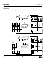
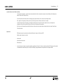
Basically there are two different types of connections between ML Gateway and the supported device (home automation systems).
Ethernet or RS232 connection. The connection types are illustrated in two examples below:
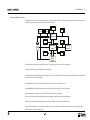
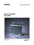
Ethernet connection - Example with ethernet connection (LK IHC)
Internet
Router / switch
Ethernet
Home automation system
Master Link system
Energy
control
Room 1
Bang & Olufsen
(( ))
Heat
control
Sensors
Alarm
IHC
Modem
Operation
switches
Lighting
Controller
ML Gateway
Room 2
(( ))
Phone
Room 3
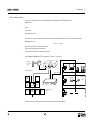
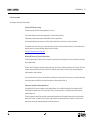
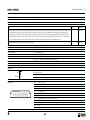
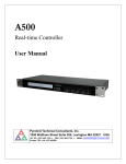
RS232 connection - example with RS232 connection (KNX)
Router / switch
Internet
Ethernet
Home automation system
Energy
control
Sensors
Room 1
5
1
6
9
ML Gateway
5
1
Environment
control
Master Link system
RS 232
6
Room 2
9
Data
Interface
Operation
switch
Lighting
Room 3
Bang & Olufsen
4
Installation overview
5
Survey of connection types
Direct Ethernet connection:
Use this option for systems with a network interface, and provide the IP address of the system.
The IP address has to be in the form xxx.xxx.xxx.xxx (for example: 192.168.1.200).
Some systems requires a TCP port number on which it expects incoming connections. Port 23 (Telnet port) is the most common default value.
Depending on the system, login and password information may be required. Default values will be suggested when available.
Direct RS232 connection:
- ML Gateway has one RS232 interface for connecting to external systems.
Only one system can be connected to the interface at a time, so when configuring ML Gateway, only one system is allowed to be set up on RS232.
A notice will appear if the interface has already been reserved for another system.
(The message RS232 port in use by MLGW Protocol appears on the screen).
- Some devices may require hardware flow control. In this case, verify that you are using a fully wired cable. Examples are Lutron HomeWorks
processors and Lutron Radio RA interface.
- Make sure to use high quality cables with proper shielding to avoid interference.
If the distance to cover is excessive, use a lower bit rate, or use an RS232 to Ethernet interface next to the external system. This last recommendation
also applies in case of interference or ground-loop problems.
- For information regarding the RS232 connector pin assignment, please refer to the appendix -> technical specification.
Using RS232 to Ethernet interfaces:
- For systems with an RS232 interface, it is also possible to use an RS232 to Ethernet interface. This way, the network installation can be used
instead of having to run a long RS232 cable between the system and ML Gateway.
- You should configure the interface for the correct RS232 parameters (bit rate, flow control, etc.).
- Parameters to configure on ML Gateway are the IP address and TCP port number of the interface.
Installation overview
Ethernet connection (RJ45)
- LK IHC (Intelligent House Control, Viewer models only)
- Lutron: Grafik Eye (GRX), Grafix QS (QSE), Home Works, Home Works QS, Home Works Radio Ra2, Radio RA,
- KNXnet (IP tunneling)
-Crestron
-Clipsal
RS232 connection (D9SUB)
-Clipsal
-Dynalite
- Lutron Grafik Eye (GRX), Lutron Grafix QS (QSE), Lutron Radio RA
- Lutron Home Works Interactive
- KNX (FT 1.2)
- Conson Concept XP (converter from RS 485 to RS 232 is needed)
-Crestron
! For RS232 connectivity, check that the RS232 protocol is not already reserved by MLGW Protocol (see link) when setting up the product.
! Do not use RS232 cables that exceed a length of 10 meters. It is recommended to use a cable between 2-5 meters.
6
Preparing setup
7
Preparing setup
Configuration of IP address
When ML Gateway is delivered, the IP address is set to a static value. The IP address for ML Gateway is 192.168.1.10 (factory default).
Depending on the customer’s network settings, it may be necessary to change the IP address in order to fit the network range. Follow the
procedure below:
- The first step is to determine the network setup in the installation (IP address range, DHCP/non-DHCP). To do this it is necessary to access the
customer’s router.
- Connect the ML Gateway with an ethernet patch cable to a computer with ethernet connection and web browser. On older computer models, it
might be necessary to use a cross-wired ethernet patch cable.
- Set the IP address on the computer to a static value in the same IP address range as the default value, eg. 192.168.1.11, and the subnet mask to
255.255.255.0 (for information about how to access settings, refer to the desired OS below):
Windows XP:
- Start -> Settings -> Network Connections -> right-click on Local Area Connections and choose Properties -> choose Internet Protocol (TCP/
IP) and click Properties.
Windows Vista:
- Start -> right click on Network and choose Properties -> click Manage Network connections -> right click on Local Area Connection and
choose Properties (if a security message appears, choose continue) -> choose Internet Protocol Version 4 (TCP/IPv4) and click Properties.
Windows 7:
- Start -> Control Panel -> Network and Sharing Center -> Change adapter settings -> right click on Local Area Connection and choose
Properties (if a security message appears, choose continue) -> choose Internet Protocol Version 4 (TCP/IPv4) and click Properties.
MAC:
- Click on System Preferences -> click Network -> click Advanced -> click TCP/IP.
Preparing setup
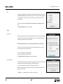
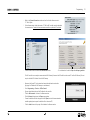
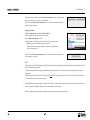
- Open a web browser and enter http://192.168.1.10 in the address field.
Now the ML Gatway web interface appears.
- Click the Setup button to access ML Gateway setup functions.
Now the login box appears on the screen.
- Type admin in both fields and click OK.
(Username is always ‘admin’. The password can be changed by the user later).
Now the web-based user interface appears on the screen.
- Click the tab System and then Network.
8
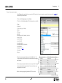
Preparing setup
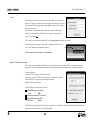
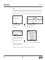
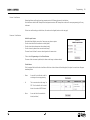
In Network Settings it is possible to define the connection possibilities of ML Gateway.
The aim here is to fit the network settings which was observed in the router before.
The default Hostname is ‘mlgw’. This can be changed, eg. to ‘mlgw1’ or ‘mlgw2’
(if there is more than one mlgw in the installation).
! It is important that the hostname is defined, otherwise ML Gateway can not be
found using Multicast DNS (also known as mDNS or Bonjour).
If the network is a DHCP setup, this can be selected, but it is recommended to use
a static IP address for ML Gateway.
If the network is a non-DHCP setup, the IP address must be defined manually in
order to fit the IP range in the router. This means that the first 3 'octets' must be
the same as the network setup in the router configuration.
-Choose Static connection and fill in the fields for:
IP address, Subnet mask, Gateway, DNS server.
Tip !
An easy way find the addresses for Gateway and for DNS server is to:
PC: Open a command prompt (cmd in Windows), and type ipconfig /all.
Mac: Click System Preferences and then Network (Router = Gateway).
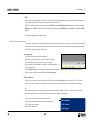
-Click Apply settings to apply settings immediately.
! After applying new settings, it is necessary to reconnect the web browser to the new address. In case of problems finding ML Gateway, the IP
address can be reset to default using the setup button on the front panel (see link).
If the computer supports Multicast DNS (default on Mac/Linux, utility required for Windows), ML Gateway can be found by typing mlgw.local in
the browser’s address field.
The next step is to mount ML Gateway in the installation setup. It is recommended to use the angle bracket for a rack-mout solution (see next
page).
9
Preparing setup
10
Installation and connection
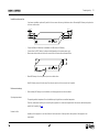
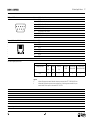
A rack-mount installation is preferred if possible. In this case mount the two angle brackets as shown. Alternatively ML Gateway can be placed on
its feet on a stable surface.
Max. 10mm
Max. 10mm
RS232
ML
- Connect the Master Link cable from the installation to the ML socket on ML Gateway.
- Connect either the RS232 cable or the ethernet cable (depending on the communication type).
- Mount mains cable and the wire holder with screw to fasten the mains cable as illustrated below.
RS232
ML
- Mount ML Gateway in the rack system or place it on a stable surface.
Now ML Gateway is ready for further setup. Press the mains switch on the front to switch on the product.
Rack-mount warnings
! When installing ML Gateway in a rack installation, the following precautions must be considered:
Operating temperatures
The operating ambient temperature of the rack installation may be higher than room ambient temperature.
Therefore, consideration should be given to installing the equipment in an environment compatible with the maximum ambient temperature
specified for the product (see link).
Reduced air flow
Installation of the equipment in a rack should be such that the amount of airflow required for safe operation of the equipment is not
compromised.
Router setup - port forwarding
11
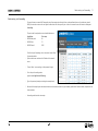
Router setup - port forwarding
To ensure that users can access ML Gateway (to control home automation functions) from a web panel/smart phone on the wide area network
(WAN), the network router must be configured to allow data traffic from specific ports. In the most common routers this feature is called port
forwarding.
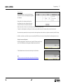
The ports used for web panel access and mobile devices are:
Application:Port range:
- MLGW Web panel
80
- MLGW Telnet
23
- MLGW Protocol
9000
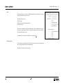
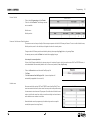
To define the port forwarding rules in the network router follow
the procedure below.
- Open a web browser and enter the IP address of the network
router.
- Choose ‘Admin’ as user and type in the password to login.
- Go to the port forwarding section
(typical named Applications & Gaming).
- Type in the previously stated port settings (see example here).
! Be aware of that setup layout and names of menues in the costumers router may vary between types/brands of network routers, compared to the
shown example.
- Save settings and leave the router setup.
Setting up ML Gateway
12
Setting up ML Gateway
Additional information
To set up ML Gateway it is necessary to access a web-based user interface. The web interface is organised into a series of screens which can be
selected by means of the navigation bars.
Please avoid using the browser’s back and forward navigation buttons, as you may loose the information you are entering. Also note that changing
to another screen does not save the modifications you have made. There are Apply or Save buttons next to most controls and data fields.
On-line help
All screens on the web interface have a link to the on-line help. Clicking on this link will open a new browser window showing the relevant section
of the help file. At the top of each help page there is a link to the table of contents.
Login
- Switch on the ML Gateway (for information about the front panel indicator and the setup button, refer to technical specifications (see link).
- Connect the service PC with an ethernet cable to the network connection (to a free port in the router/switch).
- Access the web-based user interface by typing the IP address defined earlier (during Configuration of IP address) for ML Gateway in the address
field of the web browser.
Now the ML Gatway web interface appears.
Now the login box appears on the screen.
- Click the Setup button to access ML Gateway setup funtions.
-Type admin in both fields and click OK.
(Username is always 'admin', the password can be changed by
the user later).
Setting up ML Gateway
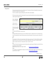
Info
The first picture that appears on the screen after a successful login is the Info screen. This section,
called Project information, provides the opportunity to enter information regarding the project.
It is recommended to fill in the fields in order to make it easier for future service. Follow the
procedure below:
- Fill in the four fields for Project name, Customer, Programmer and Programmer contact
info.
-Click Update information to save the information.
System
Date & Time
ML Gateway can get its system time from the BeoLink sysrem, and this is the recommended option.
In this case the time will be constantly synchronised to the clock of the main BeoLink product.
Alternatively, the date and time can be set manually.
! Note that ML Gateway will loose its time setting if powered down for several hours.
System time is useful for monitoring events and for examining the system and error logs, but
correct time setting is not critical to the system.
- Click on the tab System and then Date & Time.
- Choose the preferred option for time and date.
- Click Apply date and time settings to apply settings immediately.
Text size (optional)
The web-based user interface may be too wide for low resolution screens such as those of mobile
Internet devices, subcompact laptop computers, or old laptop computers.
In this case, a more compact style for the user interface can be selected.
Note that most web browsers have text size and screen zoom options, which allow for further
adjustment of the interface.
-Click Switch to .... to toggle between low and high screen resolution.
13
Setting up ML Gateway
14
Password
The system password is used for accessing both the web user interface and the command line
interface (CLI). Logging in to the web interface requires entering ‘admin’ for both the user name,
and the password. The factory default password is also ‘admin’. Logging into the CLI requires
only entering the password.
The password can be changed here to avoid unwanted access. If the modified password is
forgotten, it can always be reset to the default value. This requires an execution of service
function 2 (described here link) .
- Fill in the fields for current and new passwords (twice), and click Update password to save the new password.
If the default password is not changed, this notification is displayed on the right side of the
screen. This will disappear when the password is changed.
! It is highly recommended to change it to a unique password.
Master Link Gateway Protocol settings
The ML Gateway protocol is available on RS232 connections and as TCP socket connections (ethernet RJ45). This is a proprietary protocol for
communication with general-purpose home automation controllers. Multiple simultaneous ML Gateway protocol connections are supported.
The options available are:
- Availability and TCP port number on the network connection.
- Authentication required on TCP (Ethernet). Can be ticked if it is required that the connected
Home Automation has to start logging in with Username and Password.
- Availability and bit rate on RS232 port.
The default Master Link Gateway Protocol settings are:
Enable MLGW protocol over ethernet
IP port
9000
Authentication required on TCP (Ethernet)
Enable MLGW protocol over RS232
RS232 bit rate
9600 bps
! If the RS232 port is already configured for another device, a message is shown and selection is disabled. If RS232 is enabled for MLGW protocol,
the product can not be used with eg. Conson and KNX installation.
Setting up ML Gateway
Users
ML Gateway keeps a list of users that, individually (depending on the access level), can access
the external interfaces and services such as:
-
-
-
-
ML Gateway Protocol access
Web Panel access
Publishing service access (mobile applications)
Room access control
Defining users is important but this can not be made yet. The list of available rooms is taken
from the active configuration, therefore it is important to make sure that rooms are defined
and testet before setting up users.
An explanation for this section will follow later in the guide (see link).
Basic setup done
The basic setup is now completed for ML Gateway, but before continuing to the programming
part, it is recommended to check for software updates.
Please follow the procedure on the next pages.
15
Setting up ML Gateway
Software update
There are two methods for updating ML Gateway software. One for Internet access and one for no Internet access:
Internet access
When ML Gateway is configured to have Internet access, it provides the opportunity to check for new software on-line and download the most
recent version.
- Click on the Tools tab and choose Software Update. Use the Check available software online button to check for the latest available software. The online version will be displayed
together with the currently running version. Internet access of ML Gateway requires two
conditions:
- The installation network has direct access to Internet (no proxies).
- The network settings for ML Gateway are correctly set up.
If the network has a DHCP server, connect via DHCP in order to get all these settings automatically. You can revert to static IP address later if
needed, while keeping the other settings provided by the DHCP server. Most DSL routers nowadays are DHCP servers by default.
- Select the Update from on-line version... button to download and install the new software.
No Internet access
If ML Gateway has no direct Internet access, it is possible to upload and install a software image file from a location stored on your computer.
- Navigate to the Load new software.. section and click Browse... . When the navigation box
appears, choose the destination and software file. Click Update software.
! Do not switch off ML Gateway during the installation of new software, as this may
result in a corrupted system.
16
Setting up ML Gateway / Programming
17
Restarting ML Gateway on factory-installed software
If a software update causes ML Gateway to fail (for example due to power failure during flash update), the unit can be restarted using the original
factory-installed software.
To do this, switch ML Gateway off, and while pressing the setup button, switch it back on. Release the setup button after 5 seconds. This will start
the system using the original factory software, but will not fix nor replace the ‘broken’ software. You need to log into the system and perform a
software upgrade to fix the broken software.
If you suspect that the failure is inherent to the latest software installed (and not a failure during the flash process), you can manually download an
earlier software version from BeoWise to your computer, and perform a software update from that file.
Software update complete
When it is confirmed that ML Gateway has the latest software, the next step is to define devices and resources. Please follow the procedure on the
next page.
Programming
Additional information
The programming section provides the opportunity to define how BeoLink products and the home automation systems interact.
The programming section in ML Gateway consists of two main elements:
- Devices (including Resources for BeoLink, Virtual buttons, Home automation system)
- Macros
Refer to the following pages for information about setting up devices and resources. Macros is not described since this is individually for each
home automation system.
Programming
18
Devices - setting up resources
The next step is setting up resources for each device. Devices is the basic elements which ML Gateway looks into.
Devices can be:
-BeoLink
- Virtual buttons
- Home automation systems
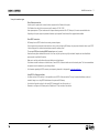
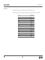
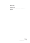
The resources area is where you identify all the necessary components with which ML Gateway will interact. Each device contain individual
Resources which can be:
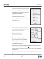
➀ Devices
➁ Resources
- Setup and settings for BeoLink rooms / BeoLink products
- Setup and settings for scenes with virtual buttons
- Configuration and definitions for home automation systems
Survey of Devices and Resources in a ML Gateway setup: ➀ = Devices
➀ Mobile device
➁ - Virtual buttons
➁ - Scenes
➁ = Resources
Internet
Router / switch
Ethernet
Home automation system
Master Link system
Energy
control
Heat
control
Sensors
Room 1
(( ))
➀ Master Link
➁ - Rooms
➁ - Products
Alarm
IHC
Modem
Operation
switches
Lighting
Controller
Bang & Olufsen
ML Gateway
Phone
➀ Home automation system
➁ - Connection
➁ - Project
Room 2
(( ))
Room 3
Follow the procedure on the next page to define the supported device (home automation system).
Programming
19
Devices - Home automation system
Use the Devices tab to specify the devices connected to ML Gateway. For information regarding supported devices please refer to page 34, and
then follow the procedure below:
- Click on the tab Programming and then Devices.
- Click in the field for Add new device. The following options are available:
-Clipsal
- Conson XP
- Custom strings (up to 4 drivers)
-Dynalite
- IP Camera
- KNX / EIB
- Lauritz Knudsen, IHC, Schneider, LexControl
- Legrand / BTicino
- Lutron Grafik Eye
- Lutron Grafik QS
- Lutron HomeWorks
- Lutron HomeWorks QS / Radio Ra2
- Lutron Radio RA
- Scheduler** (see link)
-SmartHouse
-Vantage
- Choose the relevant supported device and click the Add button. The
Configuration box (and Resource box) for the chosen device now appars
on the screen.
Connection method
RS232 / RS232 over ethernet / Ethernet
IP address
xxx.xxx.xxx.xxx
Options
for
Ethernet
IP Portxxxx
Loginxxxx
- Fill in the empty configuration fields which are necessary for ML Gateway
to communicate with the supported device. The number of options may
vary depending on the device.
! Refer to the next page regarding limitations of RS232 connection
Password xxxxxxxx
Bit rate
9600 / 19200 / 38400 / 57600 / 115200
Hardware flow control:
x
Data bits
7 bits / 8 bits
Parity
No parity / Odd / Even
Stop bits
1 bit / 2 bit
Options
for
RS232
continues on next page...
Programming
20
! RS232:
Only one system can be connected to the interface at a time, so when configuring ML Gateway, only one system on RS232 is allowed to be set up.
It is very important that the RS232 settings fit the settings for the connected device.
If RS232 is the preferred connection type, and if the message RS232 port in use by ML Gateway Protocol appears on the screen, it is because
MLGW protocol over RS232 in enabled. For this connection type it is necessary to disable MLGW protocol over RS232, under System -> MLGW
Protocol.
- Click the Save settings button to apply the settings.
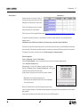
Resources - Home automation system
The purpose of resources here is to identify the configuration (components) of the home automation system. All resources tables contain an empty
last row. Use this row to define new resources. Most drivers allow automatic detecting of resources, others must be added manually by uploading
a definition file. Some drivers supports both functions.
Auto configuration
- Click the Test button to start testing the configuration.
- Activate one or more of the resources (e.g. press a button on a keypad).
This must be done for each button to be used in the configuration.
- When all resources have been added the configuration, click the Cancel button
to stop the test function.
- Click the Show detected button that appears below the resources table (a new list will appear with the resources detected during the test).
- Select the resources to add to the resource tables and press Apply changes.
Manual configuration
Drivers that do not support the auto configuration function does not have the Show detected button (e.g. Lauritz Knudsen - IHC/Schneider,
LexControl). In this case, a definition file containing the configuration of the home automation system, must be uploaded to the ML Gateway.
IHC:
Before continuing adding resources, ensure the IHC controller has software version 2.7.166 or newer. This is necessary in order to be able to
connect and communicate with the controller. To check the software version, follow the procedure below:
-
-
-
Connect the IHC controller with a USB cable to the service PC.
Open Internet Explorer, type USB in the address bar and press enter.
(LK IHC Control interface appears)
Choose LK IHC Administrator
Programming
21
- Refer to the System information window and confirm that the software version is
2.7.166 or higher
! If the software version is older than version 2.7.166 the IHC controller must be updated to
the newest version. Contact the home automation installer to update the IHC controller.
- Choose Access control from the LK IHC Administrator menu
- Put a checkmark in the box for Open for third party products
The IHC controller is now ready to commnuicate with ML Gateway. Disconnect the USB cable from the service PC and the ML Gateway. The next
step is to load the IHC definition file to the ML Gateway.
- Reconnect the Service PC to the network and access the web-based user interface
(by typing the IP address for ML Gateway in a web browser).
- Go to Programming -> Devices -> IHC/LexControl
- Type an optional description and the IP address for the controller
- Click the Add resources... button in the Resources section.
- Click the Browse button to open the Open popup window.
- Choose the definition file from the project and click Open (contact the home automation
installer regarding how to export the definition file to the service PC).
- Click the Load button and the project file is loaded to the Resource section.
Programming
22
KNX / EIB:
The KNX controller only supports one user on the system (web interface) at a time. This means that the ML Gateway must be disconnected from
the network when web interface is accessed (e.g. when the definition file is transferred to the service PC or when programming the device).
When the definition file is exported to the service PC, reconnect the ML Gateway to the network and continue with the configuration below:
- Enter the IP address for the controller
- Enter the IP port for the controller
- Click Save settings
- Click the Browse button in the Resources section
(a pop up box for choose destination file appears).
- Choose the definition file from the project and click
Open.
- Choose replace or append according to the
situation.
- Click the Upload CSV resource file button and the
project file is loaded to the Resource section.
- Enter the Group address for the resource
- Choose the Data type (Boolean is default)
-Click Apply changes.
- Select the desired resources (with checkmarks in the boxes).
- To finish the selection click the Add selected resources button
The configuration and resource screen now appears on the screen, where the selected resources are visible.
Programming
23
Devices - BeoLink
- Click on the tab Programming and then Devices.
- Click in the field for BeoLink. The following resources
are now available:
BeoLink rooms
BeoLink products
Resources - BeoLink rooms / BeoLink products
The resources screen is where you identify all the necessary components with which ML Gateway will interact. The aim is to define BeoLink rooms,
BeoLink products, events for the schedulers, and keypads or buttons for external systems.
Changes made to ML Gateway must be saved either by selecting the corresponding Apply button, or by pressing Enter.
For removing resources, select the Delete check marks before applying changes.
Auto setup of rooms and products
If there is a Beo5/6 project available in the customer setup, and it contains all rooms in whitch you need to receive LIGHT and CONTROL events, it
can be downloaded and automatically added to the list of rooms and products (if not, skip this step).
- Click on the Browse button and choose the Beo5/6 project file.
-Click Open.
-Click Load resources from Beo5 project file... (rooms and products will
automatically be appended to the current list).
BeoLink rooms
Rooms are needed for receiving LIGHT and CONTROL events from Beo4/Beo5. These
events are associated with rooms, where more than one product could possible receive
the same remote control command. The purpose of the table under the BeoLink rooms
section is to define the rooms from which you need to receive light and control events,
and to dedicate a room number to each room.
- Name the desired rooms for programming in the table and give each one a specific
number (the sequence has no significance).
Programming
BeoLink products
BeoLink products have no fixed address. Therefore, it is
necessary to manually assign an address in the column
MLN (Master Link Node) according to a room number.
Once you finish addressing each product, you need to
associate that address with the actual products.
Click this link to see a full list of compatible BeoLink products: http://mlgw.bang-olufsen.dk/source/documents/MLGW product compatibility.doc
This procedure is called product assignment. It is recommended to use continuous numbers starting with 1 (this will simplify the product
assignment process).
! AudioMasters in option 0 should not be included in the list because they are controlled through the VideoMaster.
The purpose of the table under the BeoLink products section is to define which product each room has, and what MLN (Master Link Node) each
product is dedicated. If BeoLink products are added or replaced, the procedure must be repeated so ML Gateway can identify the new products.
The assignment af the products can be made in two ways: All product assignment or Assign single product.
All products assignment:
Navigate to Programming -> Devices -> Beolink products
Click the All product assignment... button (a new window with a survey of link rooms and products appears (example).
Click the Start product assignment button.
Wait approximately 1-5 minutes for ML Gateway to be ready for product assignment.
When the text ‘Please wait‘ changes to ‘0 product activations so far’, the ML Gateway
is ready (the front panel indicator will flash red rapidly).
- Activate the product, by selecting a source, to switch on the product. Remember:
-
-
-
! Main products can be activated by selecting any source.
! Link products must be activated by selecting a source from the main room
(do not use local sources).
! Allow at least 20 seconds and no more than 5 minutes between product activation.
In setups that includes a BeoSystem 3, all tasks performed by external equipment (such as projector lifting, automated doors etc.) must be finalized
before proceeding.
Product marked to be skipped must be activated in order to get to the correct MLN values assigned.
24
Programming
25
To terminate product assignment click the End product assignment button, or press the setup
button on the front panel (or wait for 5 minutes timeout).
To abort, click the Abort product assignment button, or press and hold the setup button on
the front panel for 3 seconds.
Assign single product:
- Navigate to Programming -> Devices -> Beolink products
- Use the drop down box to choose the product to assign
- Click the Assign single product... button
- Activate the product, by selecting a source, to switch on the product. Remember:
! Main products can be activated by selecting any source
! Link products must be activated by selecting a source from the main room
(do not use local sources)
To abort, click the Abort product assignment button, or press and hold the setup button on
the front panel for 3 seconds.
Note!
- There are limitations to BeoLink Wireless products. ML Gateway has no way of distinguishing between different units in a wireless setup, therefore
you cannot identify them individually.
- If more products are activated during product assignment than have been defined on the Resources screen, these are added as new resources
automatically.
- Product assignment can be started from the front panel (see link), without using the web interface. This can be useful for ML Gateway protocolonly installations where no further setup is needed.
! During product activation, main products in link rooms (i.e. in Options 5 or 6) must be activated using a source from the main room (not a source
local to the product). Otherwise ML Gateway will not receive feedback from that product.
- When the product assignment procedure is completed, continue to setting up sources on the next page.
Programming
Devices - Virtual buttons
External applications and the web panel can generate events on ML Gateway by means of virtual buttons.
Virtual buttons are called via ML Gateway Protocol and generate events on ML Gateway that can be used for macro programming just like any
other event.
If there is no need for setting up virtual buttons, this section can be skipped (continue on the next page).
Resources - Virtual buttons
Labels for special rooms
Beside the defined BeoLink rooms earlier, 3 extra rooms are shown as options:
- One for actions that affect the residence as a whole (global).
- One for actions that are relevant near the residence (nearby).
- One for actions only relevant from a remote location (away).
The name for each of these 3 rooms can be configured on this same section.
- Click on the tab Programming and then Virtual buttons.
The name of each extra room is predefined, but these can be change to whatever desired.
Virtual buttons
Fill in the required fields to define the virtual buttons. Each time a button has been defined and applied, the option for a new button will appear
immediately below.
- Name:
A name for the virtual button, used for
monitoring and macro programming.
- Id: This is a numeric value in the range 1 to 255. This is the identifier for the virtual
button to be used on MLGW Protocol.
- Room: A room with which to associate the button (see below).
26
Programming
27
Presentation hints:
Here is an explanation for how the virtual buttons are
presented to the user on a mobile application (graphical
user interface):
- Always visible: this is a higher priority button that
should always be on-screen, whereas other buttons
could scroll off-screen on the mobile user interface.
- Require confirmation: ask the user for confirmation to avoid accidentally calling this action.
- Compact: the mobile application could represent this button using a smaller screen area (for example, side by side with other buttons).
Room selection and presentation hints are only relevant for mobile applications which obtain their configuration automatically from ML Gateway.
! By default, virtual buttons are hidden: they can be activated by MLGW Protocol, but they will not be published for mobile applications to show.
Saving the sources configuration
- Before the configuration of virtual buttons can be saved, ML Gateway must be in test
mode. Click the Test button and the greyed out Save button becomes visible.
- Click the Save button to activate and save the settings for virtual buttons.
TIP!
Click here to see more information about configurations of ML Gateway.
Programming
28
Setting up Sources
The Sources section allows to define sources for each BeoLink product. This information will be used by mobile applications for generating a user
interface where each product contains the relevant sources.
This section is only relevant for supporting mobile applications, and has no effect on macro programming.
! If BeoLink resources have been uploaded from a Beo5 project file, the sources screen should automatically contain most information necessary (with
a default UI type field according to the source).
- Navigate to Programming
and click the tab Sources.
A list of sources can be
defined for each product.
The information to provide for
each source is the following:
-
-
-
-
-
Source:
This is the actual Beo4/5/6 command for selecting the source.
Name:
This is an optional label to show with the source. Try to use a short label (no more than 5 or 6 characters) so that it can fit on less space on the user
interface. The recommendation is to leave this field empty unless you need a specific description for this source (e.g. name of a set-top box or DTV
service).
Dst:
This is equivalent to the A/V button on Beo4, or the Destination field for BeoLink commands in macros. This field should be filled in automatically
depending on the source; you can also select AUTO in order to retrieve the default setting for that source type. You can modify this setting if
needed, such as selection of audio sources on video products on Option 1 or Option 5 or vice-versa.
Link:
In the case of a link product having local sources, sources from the main products are selected using the LINK modifier (just as with Beo4). This may
also be necessary for products in OPTION 4.
Important: Many BeoLink products do not support this modifier.
Click here to see survey of compatible products.
UI type:
This is an indication to the mobile application on what type of user interface is needed for operating the product. Choose the type that most suits
your specific source or set-top box.
Click here to see survey of default UI types.
Continues on next page...
Programming
Support for HDMI matrix
MLGW provides support for unconventional source selection commands where source selection is a sequence of more than one commands.
HDMI matrix sources 01 to 32 can be selected on the source drop-down menu. These whole sequence of commands will be published to the
mobile application.
! Note that an updated version of the mobile applications must be used that fully support source selection sequences.
Saving the sources configuration
- Before the configuration of sources can be saved, ML Gateway must be in test
mode. Click the Test button and the greyed out Save button becomes visible.
- Click the Save button to activate and save the settings for sources.
TIP!
Click here to see more information about configurations of ML Gateway.
29
Programming
Setting up users
Users
ML Gateway keeps a list of users that, individually (depending on the access level), can access the external interfaces and services such as:
- ML Gateway Protocol access
- Web Panel access
- Publishing service access (mobile applications).
To add new users follow the procedure below:
- Navigate to System and click on the tab Users.
- Click the Add user button on the left side of the screen (a new window with user rights and available rooms now opens. Fill in the options).
User name / password:
User name and password are free text values. If using more than one word, or international
characters, please check that there are no encoding incompatibilities when accessing ML
Gateway.
There is no default password for users, so a new password must be supplied at least once. When
modifying user properties, leaving the password field empty means no password change.
Hidden user flag:
When an external controller is interacting with ML Gateway, a user can be assigned for
authentication. However, this is setup during installation of both systems (ML Gateway and
controller), and the users should not be able to modify these settings. For example, if the user
name or password are changed, the controller will no longer interact with MGLW. When this flag
is set for a user, it will not appear on the web panel user management page.
User management flag:
Indicates whether this user can set up and configure other user accounts by means of the web
panel. The usual case is to give the home owner access to user management. A user manager
will have an extra option on the web panel for managing users, very similar to the user setup
screen for the installer. The differences are that users with hidden flag will not show, and the
hidden property will not be available.
It is important to have at least one user manager (e.g. the homeowner) to avoid service calls for setting up users.
30
Programming
MLGW Protocol access flag:
Indicates whether the user can establish a MLGW Protocol connection (provided MLGW Protocol
authentication is enabled). This property is needed for mobile applications and external
controllers.
Web panel / publishing service access flag:
Indicates if the user can access the web panel, and if a mobile application can get configuration
information by means of the publishing service. Disable this property for external controllers
which only use MLGW Protocol.
List of rooms to access:
Indicates which rooms the user will have access to on the web panel or on the mobile
application. For example, children should not have access to scenes/sources on the main
bedroom, or scenes accessible from outside the house (Global, Away).
31
Programming
32
Macros
Macro programming
The interaction between the different devices connected to ML Gateway is defined by means of macros. A macro consists of a set of events and a
list of commands.
Whenever any of the events defined in a macro occurs (for example, a key press on a keypad, or a Control command on Beo5), the macro is
triggered. This means that all the commands in that macro will be executed in order.
To define a new macro:
-Select Programming - Macros.
- Click the Add macro button appering on the macro list.
- Define a name for the new macro and click Update name.
Copying macro definitions
A complete macro can be duplicated using the Clone button. This will make an exact new copy of a macro.
Also, selected events or commands can be copied from one macro to another. Select a group of events or commands using the check boxes, and
use the Copy buttons. These copied events or commands can later be pasted into another macro.
Copied events and commands are stored independently, so you can copy both events and commands and then paste them into another macro.
! ML Gateway does not support inserting events or commands in existing lists.
Workaround:
1 Add the missing command to the end of the command list.
2 Select the commands between the added commands and the wanted insertion point.
3 Copy, Remove and Paste the commands.
Orphan commands and events
If commands and events are already defined for a resource, and that resource is modified to another address, the events and commands become
orphan (without an associated resource).
Orphan events or commands still works, and refers to the original addressing of the resource.
The macro screen signals the presence of orphan commands or events, and a report is available listing them all.
Programming
33
Testing and accepting a configuration
ML Gateway keeps three independent versions of the configuration. Each configuration consists of the set of devices, connection settings, resources
and macros.
At all times, the active configuration is running. The user cannot modify this configuration directly, as it could disrupt the behaviour of the
installation.
Instead the user can change the ‘edit’ configuration from the user interface. All device settings, resources and macros modified by the user do not
become active, but only change this edited configuration.
The user can test if the modifications being made work as expected by selecting the Test button in the web-based user interface. This will
momentarily stop the active configuration and run a copy of the edited configuration.
If everything runs as expected during the test, the configuration can be accepted by selecting the Save button. This way the configuration being
tested becomes the active configuration. Otherwise the Cancel button restarts the original active configuration.
Use the Discard button to delete all your edits and start over again with a new copy of Current active version.
During testing the monitor and system log screens are useful to see if the new modifications are working as expected.
When accepting a configuration, the previously active configuration is not lost, but saved as the previous configuration. Use the Previous button
to return to this saved configuration (current active version and Backup/Previous version are swapped).
All three versions of the configuration can be downloaded from ML Gateway for reference, backup, or uploading to another ML Gateway unit.
Note that the edit configuration may not to be recovered in the latest version in case of a power failure. The active and previous configurations are
always stored in permanent memory. It is strongly recommended that you accept changes to the configuration after testing, so that these changes
are not lost.
Tip!
Click here to see more information about configurations of ML Gateway.
Done
When the test is successful, the installation of ML Gateway is completed!
Supported devices
34
Supported devices
On the following pages, devices and resources for all supported systems are described. Click on the preferred system to be linked direcly to it.
- Clipsal
- Lauritz Knudsen, IHC, Schneider, LexControl
- Lutron Radio RA
- Conson XP
- Legrand / BTicino
- Scheduler
- Custom strings (up to 4 drivers)
- Lutron Grafik Eye
- SmartHouse
- Dynalite
- Lutron Grafik QS
- Vantage
- IP Camera
- Lutron HomeWorks
- KNX / EIB
- Lutron HomeWorks QS / Radio Ra2
Clipsal
The Clipsal programming model defines trigger groups and trigger actions as a way to call lighting scenes. Any scene defined by a trigger group/
action pair can be called from ML Gateway.
Clipsal resources
Resources correspond to trigger groups. Usually a trigger group is shared by a set of mutually exclusive scenes, each identified by a trigger action
within the group.
Events and commands
Whenever a trigger group is set to a new action value, an event is generated on ML Gateway. Similarly, commands on ML Gateway are setting an
action value to a resource (trigger group).
Conson XP
Connection to a Conson system is made via an XP130 gateway module. This module provides an RS485 interface, so a RS232 to RS485 converter
is needed for connecting to ML Gateway.
Conson resources
On the resource screen, define the modules you need to interact with. A module is identified by a module type and a link number. Use the
monitoring tool to analyse the events on the bus.
Events and commands
Events occurring on the Conson bus are changes on a module’s input. This is signalled as a circuit make or break event.
can send circuit make, break, or pulse (make followed by break) to any input of a module.
Similarly, ML Gateway
Supported devices
35
Custom strings
The Custom strings driver is intended to enable limited communication with unsupported home automation systems. Use of this driver requires
knowledge of the protocol for the external system. ML Gateway supports up to 4 custom strings drivers.
Resources
This driver is based on matching incoming byte strings from the external system, and sending back byte strings to it. Therefore resources are
generic strings used for matching and for sending to the system.
There are 3 parameters to each resource:
- Name for the resource.
- Whether it should be available for matching (INPUT), for sending (OUTPUT), or for both (BOTH).
- A generic character string.
In order to allow arbitrary byte values to be defined, the following coding is used:
- Any character except for backslash (\) will be given it's corresponding vaule. Non-ASCII (international) characters are interpreted as Unicode UTF-8
byte sequences.
- Backslash is used as an escape character, which gives special meaning to the character o characters that follow:
\\ (double backslash) is interpreted as a single backslash.
\r is interpreted as a carriage return character (0x0D). It will be immediately redisplayed as \0D.
\n is interpreted as a newline character (0x0A). It will be immediately redisplayed as \0A.
\" is equivalent to a double quote ("). This notation is required for import/export of resources in text form.
\xx (where x is a hexadecimal digit [0-9, a-f, A-F]) is interpreted as a hexadecimal byte value. E.g. \0A is equivalent to \n.
Any non-printable or non ASCII character entered by the user will be redisplayed as a hexadecimal sequence. Illegal or truncated escape sequences
will be marked as errors.
In order to ease the editing and sharing of string definitions, the list of resources can be exported to a text file, and imported back from a text file.
Imported resources can replace all defined resources, or be appended to the current list.
Continues on next page...
Supported devices
36
The format for the text file is specified below. This format is compatible with the standard CSV or TSV (comma / tab separated values) formatting,
so it can be processed by spreadsheet software, text editors or command-line utilities.
- Lines starting with # will not be interpreted.
- Each valid line corresponds to one resource.
- Lines must have at least 2 quoted fields. A quoted field consists of a starting double quote character (") followed by escaped string data as defined
above, followed by an end double quote character.
- If a line contains only 2 quoted strings, they will be interpreted as name and match/command string, and the resource type will default to BOTH.
- If the line contains at least 3 quoted strings, the third will be interpteted as the type. Accepted values are uppercase I for input, uppercase O for
output, and uppercase B for both. Defaults to both.
- Extra quoted fields, as well as any non-quoted data will be ignored.
- Lines with no quoted fields will be ignored.
Events and commands
Resources marked for input (or both input + output) will be searched for in all incoming data. As soon as a match is found, the corresponding
event will be generated and search will continue after the match. If the incoming channel becomes idle, then all partial matches will be discarded.
Also, whenever the channel is connected (or reconnected), a special CONNECT event will be generated in case some session-setup is needed.
Commands are all resources marked as output (or both input + output) that can be transmitted to the channel.
TCP connection maintenance (read this section if you experience periodic TCP reconnections)
In order to rapidly detect broken TCP connections, MLGW uses the standard TCP Keepalive probes mechanism: when a TCP connection is idle,
probe packets are sent periodically over the connection and an acknowledge is expected. The probe is an empty TCP packet with the request for
acknowledge flag set.
There are products with non-compliant TCP implementations which do not respond to these acknowledge requests. In such cases, MLGW will
detect a broken TCP connection and reconnect. This may happen as frequent as every 20 seconds if there is no other data on the connection.
If you experience this problem, then you must somehow force some data to be sent back to MLGW periodically, so as to keep the channel active.
For example, you can set up a scheduler loop to send a status request to the 3rd party product, or a ping/pong message. On command-line based
protocols that echo all characters typed, probably sending a carriage return character is enough for getting data back to MLGW.
What to do strongly depends on the protocol of the 3rd party system.
Supported devices
37
Dynalite
Connection to Dynalite systems can be made via the RS232 interfaces, either using MLGW RS232 port or via a Ethernet to RS232 interface. Native
Dynalite Ethernet interfaces are not supported in the current software.
Dynalite resources
The resources for a Dynalite system correspond to areas in the Dynalite protocol and programming model. Add all the necessary areas in the
resources section of the GUI.
Events and commands
A preset selection can be detected by ML Gateway as an event. The parameters for the event are the Preset number and the Bank number.
For setting up a Dynalite control to affect only ML Gateway, this control must be assigned an area number not used by any dimmer or actuator.
The available commands are
- Preset selection
- Switch area off
- Area fade UP / DOWN / STOP.
The parameters for preset selection are area number and preset number. For area off and area fading, the only parameter is the area number.
IP Cameras
Future mobile applications may include live video streams from cameras in the home. This driver provides access to IP cameras on mobile
applications. Any IP camera able to stream MJPEG should be supported.
Resources (cameras)
For each camera a name, a room, a high and a low resolution URLs should be provided. The name is for identification. The room indicates the
mobile application where to display the camera, and if Global is selected, it will display the camera on every room.
The high resolution URL is for displaying the MJPEG in full size, and the low resolution URL is used for displaying video from multiple cameras on
the screen. Low resolution URL field should point to a low bandwidth video feed, with resolution not exceeding 320x240px.
Authentication
Only http basic authentication is fully supported. Global authentication data can be set and will be used for each camera for which no particular
authentication data is set. Per camera authentication can be used by setting user:password in the URL (e.g. http://user:password@domain/camera).
If no authentication is given as part of the URL, then global settings will be used instead.
Both options work using http basic authentication. If a camera uses another authentication method, try to encode it in the URL. Note that if global
authentication is set, it can generate conflicts with your authentication method. In this case, clear the global authentication settings and use only
per-camera authentication.
Supported devices
38
KNX / EIB
ML Gateway can interact with KNX systems by means of shared variables (group addresses). The KNX bus supported is twisted pair.
Connection to a KNX system
ML Gateway can connect to a KNX system by means of KNX data interfaces. The supported interfaces are:
- PEI type 10 (BCU2, with FT 1.2 protocol) over RS232 connection.
- IP tunneling over Ethernet connection.
PEI type 16 serial interfacing is not supported. PEI 10 bit rate is fixed at the default 19200 bps. The IP tunneling interface must provide bus monitor
mode.
! Note on IP tunelling: It is usually necessary to disconnect the ETS software from the IP tunelling interface before ML Gateway can connect to the
system. Also, after disconnecting ETS, the interface can take several minutes before it accepts a new connection from ML Gateway. The same
considerations apply when switching back to ETS.
Group addresses
All interactions between KNX and ML Gateway take place by means of group addresses. Group addresses have an associated datapoint type which
identifies the type of data it holds (e.g. boolean, signed integer, etc.). It is therefore necessary to define all the necessary group addresses required
for integration with ML Gateway. If this information is not readily available, the monitoring tools can be used to track for events.
KNX resources
On the resources definition screen, you must add all necessary group addresses. Group addresses have the form a/b/c (3 level address) or a/b (2
level). The default is the 3 level addresses, but both formats are accepted. Select one of the supported datapoint types for each group address:
-
-
-
-
-
-
Datapoint type:
Boolean 1 Byte unsigned integer 1 Byte signed integer 2 Bytes unsigned integer 2 Bytes signed integer 3 bit Controlled Range:
0 .. 1
0 .. 255
-128 .. 127
0 .. 65535
-32768 .. 32767
0 .. 15
Boolean values are coded as 0 for FALSE and 1 for TRUE.
3-bit Controlled values are coded from 0 (corresponding to 0000b) to 15 (corresponding to 1111b).
Continues on the next page...
Supported devices
39
For datapoint type 3.007 (Control Dimmer), the coding is:
-
-
-
-
0: Decrease break.
1 .. 7: Decrease with step 1 to 7.
8: Increase break.
9 .. 15: Increase with step 1 to 7.
For datapoint type 3.008 (Control Blinds), the coding is similar but with Up and Down instead of Decrease and Increase.
KNX events and commands
ML Gateway generates an event whenever a group address is written to, provided the datapoint type written is 2 Bytes or less in size. An event can
be defined for a specific value set to the group address. If any of the bits is 1, then a TRUE event will be generated. Otherwise, a FALSE event will
be issued. For the common datapoint types:
- Boolean: TRUE or FALSE event, depending on the value received.
- Integer (1 or 2 Bytes): TRUE event if the value received is not 0, FALSE if 0.
! Commands can write any of the possible values to a group address.
IHC Control: Lauritz Knudsen (LK), Schneider LexControl and ELKO Living system
IHC/LexControl programming model consists of physical input and output devices plus function blocks. Function blocks implement the
programming of the system, and the interface between the programming and the actual components is made by linking physical input signals to
function block inputs, and function block outputs to actuators (dimmers, shade controllers, etc.).
The web-based user interface for the controller (LK IHC Visual software) saves all programming and setup in an XML file with the extension .VIS.
This file must be provided to ML Gateway in order to define the list of resources. Once this file is loaded into ML Gateway, all relevant resources are
selectable.
Resources available for generating events on ML Gateway are physical input signals and function block outputs.
Commands are always a logical pulse (True followed by False) on function block inputs. This way, all programming (scenarios, etc.) is implemented
by means of function blocks that can be executed by ML Gateway.
The Visual project file is absolutely necessary, since there is no way to inspect all of the events occurring on the controller. Therefore, monitoring
information will only be available for already defined resources.
Supported devices
40
BTicino
Connection to a BTicino system
Connection to a BTicino My Home system is made via an Ethernet connection to a My Home Gateway interface. Both the IP address and the TCP
port must be configured on MLGW. Note that in order to establish a communication, MLGW must reside in an allowed IP range defined in the My
Home project.
Defining Resources
Interaction between MLGW and BTicino is implemented via button presses and scenario selection. Therefore, both command modules and
scenario modules can be defined as resources.
Events and commands
Events can be either scenario selection events, or CEN events (only Basic CEN and Evolved CEN events are supported: button press/release and
extended press/release).
Commands to a BTicino system are scenario activations.
Lutron Grafik Eye
Connecting to a Grafik Eye system
All Grafik Eye interfaces are supported: GRX-RS232, GRX-CI-RS232, and GRX-CI-NWK-E. Connection to the RS232 interfaces can be done directly
using a 3-wire RS232 cable, or via an Ethernet to RS232 interface. If you use an Ethernet to RS232 interface, set it up for 9600 bps, no parity, no
flow control, 1 stop bit. Connection parameters are TCP port and IP address in case of using a network interface.
The password is only needed if using a direct network connection to GRX-CI-NWK-E. The default password for this interface is ‘nwk’.
! Make sure that you enable scene status feedback and raw feedback on the Lutron interfaces. This is done by setting the DIP switches 6 and 7 to
ON on the interface itself.
Defining Grafik Eye resources
The resources you must to define are control units and accessory controls (e.g. keypads) with which you need to interact. Each is determined by an
address in the range 1 to 8 for control units, or 1 to 16 for accessory controls. You can use the monitoring facilities to identify addresses.
Grafik Eye events and commands
Events from a Grafik Eye system can be lighting scene changes or individual key presses. Possible commands are scene changes on control units.
Supported devices
41
Lutron Grafik QS
Connecting to a Grafik QS system
Connection to a Grafik QS system is done via a QSE-CI-NWK-E interface, which allows for Ethernet and RS232 connect. For RS232
communications, set the same bit rate on the QSE-CI-NWK-E interface and on ML Gateway connection settings. Connection settings for Ethernet
are the IP address of the interface and the password. The default password is ‘nwk’.
Defining Grafik QS resources
The resources you need to define are control units and accessory controls (e.g. keypads) with which you need to interact. Each is defined by a serial
number which can be found on a label on each product, or from the control units bus status information, or by inspecting ML Gateway monitoring
information.
Grafik QS events and commands
Events from a Grafik QS system can be lighting scene changes on control units, or key presses.
Possible commands are scene changes on control units.
Lutron HomeWorks Interactive
Connecting to a HomeWorks processor
Connections to a HomeWorks processor can be done directly on Ethernet, RS232, or indirectly with a RS232 to Ethernet interface. This last option
is only relevant for older HomeWorks generations without network interface. For Ethernet connection, make sure that the HomeWorks project has a
‘telnet user’ defined with username, password, and all permissions granted.
! For RS232, hardware flow control is recommended. Be sure to use a fully wired RS232 cable in this case.
Defining HomeWorks resources
Resources on HomeWorks are keypads (both physical and phantom keypads). Keypads are identified by processor number, link number and keypad
address. Use the monitor tool to verify keypad addresses and button numbering.
Events and commands
- Events from HomeWorks include button activity and LED activity. Usually you should only use the keyboard button press. The other options are
provided for advanced use and need special care.
- Commands to HomeWorks are keypad button presses. This is general since all buttons on HomeWorks are completely programmable.
Continues on the next page...
Supported devices
42
Setup on the HomeWorks project
For direct network access, a network account must be defined in the addressing section. This account is identified by a user/password. Be sure to
enable the necessary permissions for interaction with ML Gateway. ML Gateway will need full keypad monitoring and executing button presses.
Define phantom keypads for integration with ML Gateway. ML Gateway can act on any keypad (physical or phantom), but it is recommended to
channel commands from ML Gateway to HomeWorks via phantom keypads, so the special function for integration is not mixed with standard
keypad function.
LED feedback
Advanced use only: ML Gateway can generate events from keypad LED state changes. This is provided only for advanced use, where you want to
generate ML Gateway events as a consequence of conditional, time-clock, or other non-user generated actions on HomeWorks:
-
-
-
-
-
Define a state variable (or True/False variable) which you will use in your conditions or time clock events to signal ML Gateway.
Define a phantom keypad on the HomeWorks project, and choose a button for this purpose.
Set the button type to ‘conditional’. Set the LED behaviour to ‘conditional’, on (for example) Preset 5, type scene.
On Preset 5, add the state variable with a desired value.
Configure ML Gateway to respond to the LED of that button going ON or OFF, which will be an indication that the state variable has the specified
value.
For example, use the ‘Time of Day’ variable with value ‘Day’. The LED going ON will generate an event on sunrise, and the LED going off will
generate an event at sunset on ML Gateway.
Supported devices
43
Lutron HomeWorks QS / Radio Ra2
This driver is used to communicate with both Lutron Homewoks QS and Lutron Radio RA2 systems.
Connection to a Radio RA2 system
Communications with Radio RA2 is done via the Radio RA2 Main Repeater, which allows interaction with the system via 100 programmable virtual
buttons (‘phantom buttons’). This device provides both RS232 and Ethernet interfaces.
Connection to the RS232 interface can be done directly using a 3-wire RS232 cable and it is fixed at:
- Bits per second
9600
- Data bits
8
-Parity
none
- Stop bits
1
- Flow control
none
Connection to a Homeworks QS system
Communication with the Homeworks QS system is done via the Ethernet interface on the Homeworks QS Processor. Connection settings for
Ethernet consist of:
- IP address of the Main Repeater:
192.168.1.50 (default)
-
Login:lutron (default)
-
Passwordintegration (default)
- Telnet IP port 23 (default)
Defining resources
On the device setup screen, you should identify all the components with which you need to interact. These include:
- Master Control units
-Keypads
-Interfaces
! Note that resources are the entire components and not the individual buttons within them. Each Radio RA2 resource has a name and an ID. The ID
field corresponds to the identification number in the Radio RA2 system and ranges from 1 to 100. Use the monitoring facilities or the Radio RA2
telnet terminal in order to obtain the component IDs.
Homeworks QS / Radio RA2 events and commands
An event corresponds to a button press, release, hold, or multi-tap on one of the device buttons. Supported commands are button presses, button
holds and button releases.
Supported devices
44
Lutron Radio RA
Connection to a Radio RA system
Communication with Radio RA is done via the Radio RA RS232 interface. Use a full RS232 cable between Radio RA and ML Gateway. Hardware
flow control is used, so a 3-wire connection will not work.
Alternatively, you can use an Ethernet to RS232 interface and connect via the ML Gateway network port. In this case, it is important to configure
the Ethernet to RS232 interface to use hardware flow control, 9600 bps, no parity, 1 stop bit.
The only connection setting available is the TCP port number and IP address in case you connect via Ethernet.
Defining Radio RA resources
On the resources screen, you must identify all of the buttons with which you need to interact. This includes:
- Buttons on Master Control units.
- Phantom buttons on the Radio RA RS232 interface. Use the monitoring facilities or the display on the Radio RA interface to identify individual
buttons.
! Master Control buttons that you intend only for integration (and not for lighting control) have a special behaviour. Until they have been activated
once, they will not produce a radio event. Therefore, you may not find monitoring information for these buttons. Once you define them in the
project (and Test the configuration), ML Gateway activates these buttons.
! Bridged installations are not supported. All interaction will be related to the section where the RS232 interface is located.
Radio RA events and commands
You can define events for button presses on Master Control buttons. For commands you can execute a button press on a Phantom button.
Also, you can set the LED state on a Master Control button. Note that setting the LED state only works if that button has not been assigned to
lighting control. If the button has lighting assigned to it, the LED will always show the lighting scene status regardless of any state change
command sent by ML Gateway. Use this feature to provide feedback on Master Control keypads.
Supported devices
45
Scheduler
A scheduler generates a timed sequence of events. It is possible to define more than one scheduler for the project.
On the resources screen a series of events for the scheduler must be defined with the following information:
- Event name:
This is the name of the event that will be generated. Use the same name more than once if you want the same event to be produced at different
times.
- Wait time:
This is the number of seconds since the scheduler was started (it is not relative to the previous row).
Schedulers accept 2 commands: start and stop. Starting a scheduler will start to produce events at the set times. Once the last event is generated,
the scheduler automatically restarts (only if the option Continuous is selected).
! Be careful to provide other ways of stopping a scheduler. For example, events from Beo5 or from a keypad.
Smart-House
Connection to a Smart-House system
Connection to a Smart-House system is made via an Ethernet connection to a Smart-House controller. Both the IP address and the TCP port must
be configured on MLGW.
Defining Resources
Resources can be dupline input channels, dupline output channels or functions of type sequence. Interaction between MLGW and the SmartHouse system is implemented via changes in the status of channels and the start / stop of sequences.
Events and commands
Events can be a dupline channel set, a dupline channel reset, a sequence start or a sequence stop. Commands to a Smart-House system are set,
reset or pulse a dupline channel and start or abort a sequence.
Supported devices
46
Vantage
Connection to a Vantage system
Communication with a Vantage system is done through an InFusion Dim Controller. This device has both RS232 and Ethernet interfaces.
Connection to the RS232 interface can be done directly using a fully wired RS232 cable and it is fixed at no parity, 1 stop bit, 8 data bits. Make
sure to configure bit rate and flow control as needed. Connection settings for Ethernet are the IP address of the InFusion Dim Controller and its
telnet port.
Defining Vantage resources
To program the InFusion Dim Controller, the PC tool Design Center is needed. It lets you define all components of your Vantage system, where
each one has an address called VID (Vantage Identification Number).
On MLGW you can define as resources either a button on any control, or a task. To define a resource, you need to know the Button or Task vid,
wich must be entered in the ID field.
Vantage events and commands
An event corresponds to a Button press or release, or a Task activation or deactivation. Supported commands are Button press and release,
Button press, Button release and Task activation.
Appendix
47
Appendix
Service functions
Front panel indicator
The front panel indicator indicate the state of the system, and is also used for setup button operation and BeoLink product assignment.
The normal start-up sequence displays like this:
- GREEN:
- RED: - Blinking RED: - GREEN: System power up, approx. 2 seconds.
System boot, approx. 1 minute.
Application running, and BeoLink products detection in
progress, approx. 1 minute.
ML Gateway application is now running.
Front panel indicator (LED)
Setup button
If ML Gateway encounters an unrecoverable internal error, it will signal a critical error condition. In this case, the front panel indicator will keep
flashing alternating red and green. The application is still running, but the error and system logs must be checked for diagnosis.
During software update of any of the two processor modules, the front panel indicator will flash green.
Setup button
The setup button on the front panel provides several functions. Each function is dedicated a specific number of blinks. These can be accessed by
choise through a cycle of available functions. One blink = function 1, two blinks = function 2, etc.
Survey of functions:
Function 1: Optional user event (can be used as a trigger to a macro).
Function 2: Reset password to factory default.
Function 3: Reset network settings to factory default.
Function 4: Erase entire configuration, network and password to factory defaults.
Function 5: BeoLink product assignment on the active configuration.
To select a function, press and hold the setup button. This will cycle through all available functions, and the front panel indicator blinks RED
showing the current function. Release the button at the desired function number in order to execute it. Holding the button past the last function
to return to normal operation. The setup button can also be used during system power up to recall the original factory-installed software as
described in the section ‘Troubleshooting’.
Appendix
48
Command line interface
In addition to the web-based interface, ML Gateway contains a command-line based interface (CLI). Use CLI for:
-
-
-
-
Monitoring for events / macros / commands in real time, and without occupying the web-based interface.
Basic setup of ML Gateway: network settings, MLGW protocol availability, time and date settings.
Obtaining service information.
Automating configuration of multiple ML Gateway units.
To access the CLI, use any Telnet client to connect to ML Gateway. The IP address or host name to use is the same as for the web-based interface:
use the IP address of ML Gateway, or the host name mlgw.local if your system implements multicast DNS.
Configure your telnet client for UTF-8 encoding to correctly show international characters. On connection, you will get a log-in prompt. Type the
ML Gateway password to proceed. Several CLI connections may be active simultaneously.
Use the TAB key to check for available commands, automatically complete the commands, and getting help for a command. Use the Esc key to
cancel a command and get a new prompt.
Available commands
Commands have optional arguments, with the following properties:
-
-
-
-
-
Arguments between brackets ( ‘[‘ and ‘]’ ) are optional.
Arguments separated by a vertical bar ( ‘c’ ) are mutually exclusive.
Command names and arguments are case insensitive, except for passwords which are case sensitive.
Arguments shown in uppercase indicate a literal value.
Arguments shown in lowercase indicate values you should supply.
HELP [ command ]
- Provides usage information for a command.
- With no arguments, provides help on using the command line interface.
LOGOUT [ ALL | OTHER ]
- Terminates the CLI session. Ctrl-D can be used equivalently.
- With an argument, terminates all, or all other CLI sessions.
-The INFO command shows the number of active CLI sessions.
Appendix
INFO
-
-
-
-
-
-
-
-
-
Displays product and status information of ML Gateway:
Serial number
Type number
MAC address
Network configuration
Software version
Hardware version
Number of CLI opened sessions
System time
DATE
[ yyyy mm dd hh mm ]
DATE BEOLINK
- Without arguments, displays the current system date and time.
- With BEOLINK argument, system date is set to that of BeoLink products.
- For manual date setup, provide the 5 numeric values.
NETCONFIG
[IP xxx.xxx.xxx.xxx]
[GATEWAY xxx.xxx.xxx.xxx]
[MASK xxx.xxx.xxx.xxx]
[DNS xxx.xxx.xxx.xxx]
NETCONFIG DHCP
-
-
-
-
Without arguments, shows current network setup.
With DHCP argument, gets configuration from DHCP server.
Providing one or more of the manual settings switches to manual IP configuration.
New settings apply immediately.
49
Appendix
PASSWORD old_password new_password
- Changes the system password.
MAC
- Displays the Ethernet MAC address.
MLGWPROTO RS232 [ bitrate | OFF ]
MLGWPROTO IP [ port | OFF ]
- Sets up MLGW protocol on RS232 or IP.
MONITOR
-
-
-
-
-
Starts a real-time monitoring application.
Use keys M, E, C, to toggle the display of macros, events and commands respectively.
Use the space bar to stop and resume monitoring.
Q quits the monitor application.
Any other key inserts a mark in the output.
ALLSTANDBY
- Sends all BeoLink products to stand-by. Use to check BeoLink connectivity.
COUNTERS
- Displays service counters.
50
Troubleshooting
51
Troubleshooting
Previous checks
Before setting up Master Link Gateway, it is necessary to have the entire Master Link installation working and correctly configured.
Setting up and troubleshooting a Master Link network is covered in the Master Link Handbook.
Below is a brief checklist for basic troubleshooting of Master Link:
- Before connecting any products to Master Link, verify electrical conductivity using the Master Link Tester. In particular, check the ML outlet
dedicated to ML Gateway as you probably never used this outlet before.
- Connect all products to Master Link and make the correct Option programming. It is particularly important not to have more than one Video
Master, and no more than one Audio Master in the network (Master products are configured in Options 0, 1 or 2). The rest of the products must
be configured as link products (Options 4, 5 or 6, possibly 0). ML Gateway itself has no Option programming.
- Check that all products are working, and that you can get audio from the Master products to all link products, and between the Master products.
- Connect ML Gateway to the network, switch it on and wait for startup (this takes less than 2 minutes).
- Switch some products on. Issue an ALL STANDBY command on ML Gateway using the CLI command ALL STANDBY. Check that the products
switch to standby.
Click here for information about CLI command.
Product assignment
A product does not switch on:
If you are unable to switch a product on using Beo4, be aware that some products can be configured in Option 0, 1, 4 or 5, so selecting a source
on Beo4 will not necessarily activate such products.
Troubleshooting
52
A product does not switch back to standby
If, during product assignment, a product does not automatically switch back to standby, there may be an internal address conflict between two
products, although this is highly unlikely.
- First of all, double check that all products are working properly, respond to Beo4, and can access sources through BeoLink.
- Then, repeat the configuration procedure, and verify that this same product still does not switch back to standby.
- In order to determine which other product is involved in the addressing conflict, power down other products one by one and repeat the
configuration. Start with Link products (BL Passive, BL Active), and then proceed to new products.
- Once the two conflicting products are identified, take note of type number, item number and serial number of each, and contact Shared Service
Center for assistance.
System error
ML Gateway may report a system error by alternately flashing red / green on the front panel LED.
Possible causes of system error include:
- Software fault
- Internal communication error
- H8 module error
! In case of system error, always try to solve the problem by updating the software. If this does not solve the problem, ML Gateway must be serviced.
It is recommended to use the backup file (if it exists) for ML Gateway, so programmed data can be uploaded to the replaced module.
Troubleshooting
53
After software update
ML Gateway not working after software update
Detecting if ML Gateway is running
The following are signs that the ML Gateway application is not running:
- The front panel indicator does not turn green approximately 1 minute after being switched on.
- Briefly pressing the setup button produces no visible feedback on the front panel indicator.
- The unit automatically reboots every minute or so (check for system boot indication on the front panel or critical error indication).
If the application seems to be running, but you cannot connect either via web or via telnet (command line interface), first check that the network is
working as usual; then try resetting the network settings through the front panel.
Click here for information about CLI command.
- Restarting ML Gateway with factory-installed software
If a software update causes ML Gateway to fail (for example due to power failure during flash update), the unit can be restarted using the original
factory-installed software.
To do this, switch ML Gateway off, and while pressing the setup button, switch it back on. Release the setup button after 5 seconds. This will start
the system using the original factory software, but will not fix or replace the ‘broken’ software. You must to log into the system and perform a
software upgrade to ‘repair’ the software.
If you suspect that the failure is inherent to the latest software installed (and not a failure during the flash process), you can manually download an
earlier software version from BeoWise to you computer, and perform a software update from that file.
- Erasing entire configuration before application start
If the application fails to start even if restarting on factory-installed software, there is a method for erasing the entire configuration from ML
Gateway before the application starts up. This may be useful in case of a corrupt configuration, or a configuration which causes the factoryinstalled software to fail.
The entire configuration is erased if the setup button is pressed when the application starts (front panel indicator goes from red to green) and is
released within 1 second. The procedure for this is to power up ML Gateway with the setup button pressed, and release is as soon as the front
panel indicator goes from red to green (approximately 40 seconds after power-up).
Troubleshooting
Default UI types
When importing a Beo5 XML project file, ML Gateway will assign a default UI type according to the source.
The installer should then adjust the UI type on special cases only. The default UI type adopted by ML Gateway on import is listed below:
Source
TV
RADIO
DTV2
A.AUX
V.MEM
DVD2
DVD
CAMERA
DTV
PC
V.AUX2
A.MEM
CD
N.RADIO
N.MUSIC
JOIN
Default UI type
TV
RADIO
DTV
Selection-only
V.MEM
DVD B&O
DVD B&O
Selection-only
DTV
PC
Selection-only
A.MEM
CD
N.RADIO
N.MUSIC
Generic
54
Troubleshooting
55
Survey of configuration versions
All edits are done in the Edit version (in non volatile memory which is deleted at power off). When you are editing the Current active version is still
running making sure your are not making black-out in the whole house.
All edits
Save
Load
configuration
configuration
Test
Edit
version
Power ON
Discard
Cancel
2
Current active
version
Disk
storage
Running
version
2
Previous
1
1
Save
Backup/
Previous
version
- Use the Test button to test changes made in Edit version. This will copy the Edit version to the Running version.
- Continue to Edit and Test until configuration works as expected.
- Use the Save button when configuration works as expected. This will (1) save previous Current active version in Backup version and (2) save Edited
= Running version in Current active version.
- Use the Cancel button if you want to pause your Edit/Test and return to the Current active version.
- Use the Discard button to delete all your edits and start over again with a new copy of Current active version.
- Use the Previous button to return to the last Backup version and make it Running version.
Note: Current active version and Backup/Previous version are swapped, which makes it easy to test both versions.
- Use the Tools, Configuration, Save configuration to make disk copies of Edit, Current active or Backup versions.
- Use the Tools, Configuration, Load configuration to load one of the saved versions into the Edit version. Remember to use the Test and Save
buttons to make it the Current active version.
Technical specifications
Technical specifications
Master Link Gateway
Type survey
Market
Variant
Type number
Albania, Argentina, Australia, Austria, Azerbaijan, Bahrain, Belgium, Botswana, Brazil, Bulgaria, Caribbean Islands of the Dominican Repub., Canada, Chile, Croatia, Czech
Repub., Denmark, Dubai, Egypt, Estonia, Faroe Islands, Finland, France, Georgia, Germany, Ghana, Greece, Greenland, Holland, Hong Kong, Hungary, Iceland, India,
Indonesia, Ireland, Israel, Italy, Japan, Jordan, Kazakhstan, Korea, Kuwait, Latvia, Lebanon, Liechtenstein, Lithuania, Luxembourg, Malaysia, Mexico, Morocco, New Zealand, Nigeria, Norway, Oman, Pakistan, Panama, Peru, Philippines, Poland, Portugal, Qatar, Romania, Russia, Saudi Arabia, Serbia, Singapore, Slovak Rep., Slovenia, South
Africa, Spain, St. Martin, Sweden, Switzerland, Taiwan, Thailand, Turkey, UK, Ukraine, Uruguay, United Arab Emirates, USA, Uzbekistan, Vietnam
All
1701, 1799
China (for information regarding RoHS directive please see next page)*
CN
1702, 1798
Power supply
Power consumption
Operating conditions
100 ~ 230 V AC, 50/60 Hz
Typical 2.5 Watts, standby not possible
-10 to +50 degrees celcius
Dimensions
Weight
35.5 x 4.5 x 15 cm (W x H x D)
48.3 x 4.5 x 15 cm (W x H x D - including bracket for rack-mount)
1.63 kg
Connections
Mains inlet
Live
Too see the different types of mains leads see exploded view in the
Retail Ordering System
Neutral
MASTER LINK 9
3
13
1
11
5
7
15
16
8
10
12
14
2
4
6
Pin 1
Pin 2
Pin 3
Pin 4-8 Pin 9 Pin 10 Pin 11 Pin 12 Pin 13 Pin 14 Pin 15 Pin 16 Data- -0.4V ±0.1V
Data+ +0.4V ±0.1V
ML sense
N.C.
ATI transmit (N.C.)
ATI receive (N.C.)
N.C.
+supply voltage +7V to +15V (in St By +3V to +15V)
N.C.
N.C.
N.C.
N.C.
56
Technical specifications
RS232 port, DSUB9 male
1
6
Ethernet , RJ45 socket, 10/100 Mbit/s
5
9
5
9
Pin 1
Pin 2
Pin 3
Pin 4
Pin 5
Pin 6
Pin 7
Pin 8
Pin 9
DCD (Data Carrier Detect - input)
RXD (Received Data - input)
TXD (Transmitted Data - output)
DTR1 (Data Terminal Ready - output)
GND (signal ground)
DSR (Data Set Ready - input)
6
RTS ( Request To Send - output)
CTS (Clear To Send - input)
RI (Ring Indicator - input)
Pin 1
Pin 2
Pin 3
Pin 4
Pin 5
Pin 6
Pin 7
Pin 8
TX_D1+
TX_D1RX_D2+
BI_D3+
BI_D3RX_D2BI_D4+
BI_D4-
57
* Information regarding RoHS directive
Hazardous Substance
Component name
Lead
Pb
Mercury
Hg
Cadmium
Cd
Chrome VI
Cr(VI)
Polybrominated
Biphenyl PBB
Polybrominated
Diphenyl Ether PBDE
PCBA
X
O
O
O
O
O
Legend:
O
X
Subject to change without notice
Indicates all homogeneous materials’ hazardous substances content are below ST/T 11363-2006 MCV limit.
Indicates that the hazardous substance content contained in any of the homogeneous materials of the part
exceeded the MCV limits specified in the standard SJ/T 11363-206.
Contents
Contents
Introduction ....................................................................................... 2
How to navigate this guide ............................................................. 2
Introduction
Information ........................................................................................ 3
Access ............................................................................................ 3
Information
Installation overview .......................................................................... 4
Survey of connection types ............................................................... 5
Installation overview
Preparing setup ................................................................................. 7
Router setup / port forwarding ....................................................... 11
Setting up ML Gateway ................................................................... 12
Software update ........................................................................... 16
Survey of connection
types
Preparing setup
Programming ................................................................................... 17
Devices - Home automation system ............................................... 19
Resources - Home automation system ........................................... 20
Router setup / port
forwarding
Devices - BeoLink .......................................................................... 23
Resources - BeoLink ...................................................................... 23
Setting up ML Gateway
BeoLink products .......................................................................... 24
Devices - Virtual buttons ............................................................... 26
Programming
Resources - Virtual buttons ............................................................ 26
Setting up Sources ........................................................................ 26
Supported Devices
Setting up Users ............................................................................ 30
Macros .......................................................................................... 30
Appendix
Supported Devices ........................................................................... 34
Appendix .......................................................................................... 47
Service functions ........................................................................... 47
Troubleshooting
Troubleshooting .............................................................................. 51
Technical specifications .................................................................... 57
Version 1.9 - 03.2012
Technical specifications
58