1
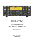
ELECRAFT K3
HIGH-PERFORMANCE
160 –6 METER TRANSCEIVER
OWNER’
S MANUAL
Revision D1, July 27, 2008
Copyright © 2008, Elecraft, Inc.
All Rights Reserved
Contents
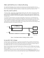
Buffered I.F. Output...................................... 38
Using Transverters........................................ 38
Scanning ...................................................... 39
A Note to K3 Owners .......................................3
Key to Symbols and Text Styles.......................3
Quick-Start Guide.............................................4
Introduction.......................................................7
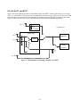
M ain and Sub Receiver Antenna Routing...... 40
Basic K3 (no KAT3 or KXV3) ...................... 40
K3 with KXV3 RF I/O Module ...................... 40
K3 with KAT 3 AT U..................................... 41
K3 with KAT 3 and KXV3............................. 42
K3 Features.....................................................7
Specifications..................................................8
Customer Service and Support........................10
Front Panel......................................................11
Control Groups..............................................11
Display .........................................................12
LEDs............................................................13
Front Panel Connectors..................................13
Primary Controls...........................................13
Multi-Function Controls.................................14
VFO T uning Controls....................................14
Keypad.........................................................15
Memory Controls ..........................................16
Message Record/Play Controls.......................16
RIT and XIT Controls....................................16
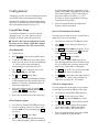
Remote Control of the K3.............................. 43
Options........................................................... 44
Firmware Upgrades ........................................ 44
Configuration ................................................. 45
Rear Panel .......................................................17
Synthesizer................................................... 48
Wattmeter..................................................... 48
Transmitter Gain........................................... 48
Reference Oscillator...................................... 49
Front Panel Temperature Sensor .................... 50
PA Temperature Sensor................................. 50
S-Meter........................................................ 50
Crystal Filter Setup ....................................... 45
Option Module Enables................................. 46
Miscellaneous Setup...................................... 46
VFO A Knob Friction Adjustment ................. 47
VFO B Knob Friction Adjustment.................. 47
Real T ime Clock Battery Replacement ........... 47
Calibration Procedures ................................... 48
Connector Groups..........................................17
KIO3 Module ................................................18
Basic Operation ..............................................21
Receiver Setup ..............................................23
Reducing Interference and Noise ....................25
Transmitter Setup ..........................................26
Voice Modes (SSB, AM, FM) ........................28
CW Mode .....................................................30
Data Modes...................................................31
M enu Functions.............................................. 51
MAIN Menu................................................. 51
CONFIG Menu............................................. 52
Advanced Operating Features.........................33
Troubleshooting............................................. 59
T ext Decode And Display ..............................33
CW-to-DAT A...............................................34
T uning Aids: CWT and SPOT ........................34
Audio Effects (AFX)......................................35
Dual Passband CW Filtering...........................35
Receive Audio Equalization (EQ)...................35
Transmit Audio Equalization (EQ)..................35
SPLIT and Cross-Mode Operation..................36
Extended Single Sideband (ESSB) ..................36
General-Coverage Receive.............................36
VFO B Alternate Displays..............................36
Alarm and Auto Power-On.............................36
Using the Sub Receiver ..................................37
Receive Antenna In/Out.................................38
Parameter Initialization ................................. 61
Module Troubleshooting ............................... 62
Theory Of Operation...................................... 66
RF BOARD.................................................. 66
KANT3 and KAT 3 ....................................... 68
KIO3............................................................ 68
Front Panel and DSP ..................................... 68
KREF3......................................................... 69
KSYN3 ........................................................ 70
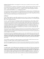
K3 Block Diagram........................................ 71
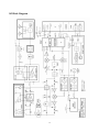
Appendix A: Crystal Filter Installation.......... 72
Index............................................................... 76
2
A Note to K3 Owners
Onbe
ha
l
fofoure
nt
i
r
ede
s
i
g
nt
e
am,we
’
dl
i
ket
ot
ha
nkyouf
orc
hoos
i
ngt
heEl
e
c
r
a
f
tK3t
r
a
ns
c
e
i
ve
r
.
The K3—like its predecessor, the K2—reflects our desire to go beyond what other high-performance
t
r
a
ns
c
e
i
ve
r
sha
veof
f
e
r
e
d.I
ti
s
n’
tj
us
tahome
-station rig; at about 8 to 9 pounds, it can accompany you
whe
r
e
ve
ryoug
o,whe
t
he
ri
t
’
soutt
oyourba
c
kpor
c
horha
l
f
wa
ya
r
oundt
hewor
l
d.Andi
t
’
st
heonl
y
rig in its class that you can build yourself. Above all, we want the K3 to be ready for any operating
s
i
t
ua
t
i
onyoue
nc
ount
e
r
,a
ndbemor
ee
nj
oya
bl
et
ous
et
ha
na
nyt
r
a
ns
c
e
i
ve
ryou’
vee
ve
rowne
d.
In addition to t
hi
sma
nua
l
,you’
l
lf
i
ndmuc
hmor
ei
nf
or
ma
t
i
onont
heK3onourwe
bs
i
t
e
,i
nc
l
udi
ng
operating tips, answers to frequently asked questions, and information on firmware upgrades.
73,
Wayne, N6KR
Eric, WA6HHQ
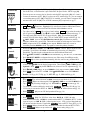
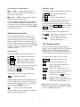
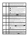
Key to Symbols and Text Styles
Important –read care fully
Operating tip
LS B
.
.
LCD icon or characters
LED
Enter keypad function
X MI T
Tap switch function (labeled on a switch)
TU N E
Hold switch function (labeled below a switch; hold for 1/2 sec. to activate)
SQL
Rotary control without integral switch
PW R
Tap switch function of rotary control (labeled above a knob)
MO N
Hold switch function of rotary control (labeled below a knob; hold for 1/2 sec.)
MAIN:VOX GN
Typical MAIN menu entry
CONFIG:KAT3
Typical CONFIG menu entry
3
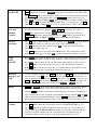
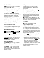
Quick-Start Guide
To get started using your K3 right away, please read this page and the two that follow, trying each of the
controls. The text uses braces to refer to numbered elements in the front- and rear-panel illustrations below. For
example, {1} refers to 1 , the mic jack. Later sections provide greater detail on all aspects of K3 operation.
The first thing you nee d to know about the K3 is that most switches have two functions. Tap (press
briefly) to activate the function labeled on a switch. Hold to activate the function labeled below the switch. In
the text, tap functions are shown like this: ME N U . An example of a hold function is C ON FI G . Additional
typographical conventions are shown on the previous page.
Try tapping ME N U {8}. T his brings up the M AI N menu. Rotating VFO B {19} selects menu entries, while
rotating VFO A {22} changes their parameters. Tap ME NU again to exit the menu.
4
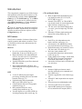
Connections
Connect a power supply to the DC input jack {26} (see Specifications, pg. 8).
On the K3/100, a circuit breaker is provided on the fan panel for the 100-W stage {30}.
You can power an accessory device from the switched DC output jack {38} (0.5 A max).
Connect an antenna to ANT1 {29}. If you have an ATU installed (pg. 22), you can connect
a second antenna to ANT2 {28}. If the KXV3 is installed, you can connect a separate RX
antenna to RX ANT IN {34}. The AUX RF connector {27} is optional; see pg. 17.
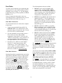
The Basics
Filter
Controls
Press P OW E R {5} to turn on the K3. If there are any error indications, refer to pg. 63.
T AP and H O LD Functions: Tapping briefly activates the function labeled on a switch.
Holding for about 1/2 second activates the function labeled below a switch.
T ap either end of B AN D {7} to select a band, and tap MO D E {6} to select the mode. Set
the AF gain using
AF {2}. Set
RF to max. S UB controls are discussed on pg. 37.
The large knob {22} controls VFO A (upper display, {10}). The medium knob {19}
controls VFO B (lower display, {11}). VFO A is main RX/T X except in SPLIT (pg. 36).
CM P / P WR is one of four multifunction controls {24}. Each has two primary
functions, indicated by green LEDs. The knob has a built-in switch; tap it to select either
CM P (compression level) or P WR (power output). Hold the knob in to access its
secondary function, M O N itor level. Tap again to restore the primary function.
Rotate the
SHIFT / LOCUT and
HICUT / WIDTH controls {23} to adjust the filter
passband. Crystal filters FL1 - FL5 are automatically selected as you change the
bandwidth. T ap either knob to alternate between shift/width and hicut/locut.
Hold
SHIFT / LOCUT to NO RM alize the bandwidth (e.g., 400 Hz CW, 2.8 kHz SSB).
Hold
HICUT / WIDTH to alternate between two filter setups, I and II (per-mode).
T ap XF IL {13} to select crystal filters manually; this also removes any passband shift.
Voice Modes
{1}
CW Mode
{36}
Data Modes
{31}
Hold ME TE R {8} to see CM P / ALC levels. While talking, set
MIC {25} for 4-7 bars
of ALC, and
CMP for the desired compression. Then return to S WR / P WR (pg. 28).
O ptional: Hold TE S T {6} for TX TEST mode; allows off-air TX adjustments (pg. 13).
Hold
CMP / PWR {24} to set speech MO N itor level; tap to return to CM P / P WR .
Hold V O X {7} to select PTT or V OX . Hold
SPEED / MIC to set VOX DE LAY .
Details: VOX, pg. 29; T X EQ, pg. 35; MIC SEL, pg. 51; SSB/AM/FM, pg. 28.
SPEED {25} sets the CW keyer speed. Hold this knob to set semi-break-in DE LAY .
Hold Q S K {7} to select full break-in (Q S K icon on) or semi-break-in. (Pg. 30.)
Hold P I TCH {18} to set sidetone pitch. Hold
CMP / PWR to set sidetone MO N level.
T ap C W T {18} for tuning aid {9} (pg. 34). With CWT on, S P O T auto-tunes (pg. 30).
To select CW text decode/display mode, hold TE X T D E C {18}; rotate VFO B (pg. 30).
CW keying is converted to DATA in FS K D and PS K D modes (below and pg. 34).
Hold DU AL P B {13} to turn CW dual-passband filter (pg. 30).
T ap MO D E {6} until you see the DATA icon turn on (see Data Modes, pg. 31).
Hold D AT A MD {18}. Use VFO B to select from: DATA A (PSK31 & other
soundcard-based modes), AFS K A (soundcard-based RTT Y), FS K D (RTT Y via data
input or keyer), or P S K D (PSK via data input or keyer). VFO A selects data baud rate
for internal encoder/decoder, if applicable. DU AL P B turns on RTTY filter (DT F, pg. 32).
Hold P I TCH {18} to select mark tone and shift (for encoder/decoder and RTT Y filter).
Hold TE X T D E C {18} to set up text decode. CW T shows tuning aid (pg. 34).
5
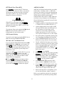
VFOs
and RIT/XIT
R ATE {21} selects 10 or 50 Hz VFO/RIT tuning. See VFO menu entries, pg. 52.
F IN E {21} selects 1-Hz steps. C O AR S E selects large steps (MAIN menu, VFO CRS).
T ap F R E Q E N T {21} to enter frequency in MHz using numeric keypad & decimal point.
T ap return (
) to complete the entry, or tap F R E Q E N T again to cancel. (Pg. 15.)
Hold S C AN to start/stop scanning. SC AN must be preceded by a memory recall (pg. 39).
The R I T and X I T offset knob {17} has LEDs that show -/0/+ offset (pg.16). T ap CL R
{16} to zero the offset. Hold CL R for > 2 sec. to add the offset to VFO A, then zero it.
Transmit,
ATU, an d
Antenna
Controls
The TX LED {4} indicates that the K3 is in transmit mode. The ∆f LED turns on if the
RX and T X frequencies are unequal ( S PL I T , R I T / X I T , cross-mode, etc.). (Pg. 13.)
X MI T {8} is equivalent to PTT {35}. TU N E puts out full CW power in any mode.
ATU TU N E {8} initiates antenna matching (pg. 22). ATU enables or bypasss the ATU.
AN T selects AN T1 or ANT2 . R X AN T selects main or RX antenna (KXV3).
NB, NR,
and Notch
T ap NB {12} to enable DSP and I.F. noise blanking. Hold L E V E L to set DSP NB level
(VFO A) and I.F. NB level (VFO B). Fully CCW is OFF in both cases. (Pg. 25.)
T ap N R {12} to turn on noise reduction. Hold AD J to tailor noise reduction for the
present band conditions (pg. 25).
T ap N TC H {12} once to select auto-notch ( NTCH icon), and a second time to select
manual notch (adds
icon). Hold MAN to adjust manual notch frequency. (Pg. 25.)
S PLIT,
BS ET,
and S UB
Hold S P L I T {13} to enter split mode (RX on VFO A, TX on VFO B). If VFOs A and B
are on different frequencies in SPLIT mode, the Delta-F LED ( ∆f ) will turn on (pg. 13).
Hold B S E T {13} to adjust VFO B / sub RX settings independently of VFO A (pg. 37).
T ap SU B {20} to turn on the sub receiver (pg. 37). VFO B controls its frequency.
Hold S UB {20} to link the two VFOs (VFO A is then the master). This allows diversity
receive with main and sub if two different antennas are used (pg. 37).
Memories,
Messages, and
DVR
To store a frequency memory, tap V M {14}, then: tap M1 - M4 {15} to save a per-band
quick memory; or tap 0 - 9 to save a general-purpose quick memory; or rotate VFO A to
select from memories 0-99, then tap V M again to save. Tap M V to recall. (Pg. 16.)
R E C and M1 - M4 {15} are also used to record & play voice/CW/DAT A messages. T he
KDVR3 option is required for voice messages and AF R E C / AF P L AY (pg. 29).
Menus
ME N U & C ON FI G {8} access the MAIN and CONFIG menus. VFO B selects entries;
VFO A changes parameters. In general, CONFIG menu entries are used less often.
T apping DI S P {8} within menus shows information about each entry on VFO B (pg 51).
Up to 10 menu entries can be assigned to programmable function switches. P F 1 and P F 2
{16} are dedicated programmable functions. Any of M1 - M4 {15} can be used as T ap
and/or Hold programmabl
ef
u
nc
t
i
o
nsi
ft
he
y
’
r
eno
tb
e
i
ngu
s
e
df
orme
s
s
a
g
epl
a
y(
pg51).
Other
Features
RX and T X EQ (MAIN menu) provide 8 bands of receive/transmit equalization (pg. 35).
T ap AF X {18} to enable the selected audio effect (see CONFIG:AFX MD, pg. 51).
T ap D I S P {8} and use VFO B to show time, supply voltage, etc. on VFO B (pg. 36).
The ALARM function (MAIN:ALARM menu entry) can be used to remind you about a
contest, net, or QSO schedule, and can even turn the K3 on at alarm time (pg. 36).
The KIO3 module provides a rich set of AF {33} and digital {32} I/O (pg. 17).
6
Introduction
This comprehensive manual covers all the features
and capabilities of the Elecraft K3 transceiver. We
recommend that you begin with the Quick-Start
Guide (pg. 4). T he Front Panel (pg. 11) and Rear
Panel (pg. 17) sections are for general reference,
while Basic O peration (pg. 21) and Advance d
O peration (pg. 33) fill in the details.
CW and Digital Modes
Built-in digital-mode demodulation with
t
e
x
td
i
s
pl
a
ye
do
nt
heK3
’
sLCD(
CW,
RTT Y, PSK31) (pg. 33)
Internal CW-to-RTTY or CW-to-PSK31
text decode/encode for casual digital-mode
QSOs without a computer (pg. 34)
CW text can be decoded and displayed as
you send –great for improving CW skills
(pg. 33)
Automatic CW/data signal spotting and
manual fine-tuning display (pg. 30)
Your K3, including any installed crystal filters
and option modules, should already be configured.
Anytime you add new filters or options, refer to
Configuration (pg. 45).
K3 Features
User Interface
The K3 offers a number of advanced features that
simplify operation and enhance versatility. These
are listed below. Refer to the indicated pages for
further details.
Dual VFOs with independent modes,
bands, and filter settings (pg. 14)
100 memories with alphanumeric labels,
plus 4 quick-memories per band (pg. 16)
Dedicated message play controls for use in
CW, data, and voice modes (pg. 30)
Real-time clock/calendar with
programmable alarm times and automatic
power-on (pg. 36)
Utility displays show voltage, current drain,
RIT /XIT offset, front panel temperature,
PA heatsink temperature, etc. (pg. 36)
Instructions for menu entries available with
one switch tap
Receiver
Up to five crystal roofing filters with
bandwidths as narrow as 200 Hz (pg. 23)
High-performance, fully independent sub
receiver, also with up to five crystal filters,
allows true diversity receive with two
antennas (pg. 37)
Variable-bandwidth crystal filters that track
DSP filter settings
Narrow ham-band front-end filters, plus
wider band-pass filters for general-coverage
receive (pg. 44)
Connectivity
Enhanced, high-speed remote control
interface with many new commands and
direct DSP access
Firmware upgradeable via the Internet (pg.
44)
Isolated PC audio input and stereo outputs
(pg. 17)
DSP
32-bit I.F. DSP for advanced signal
processing, including full stereo and other
binaural effects (pg. 35)
Passband tuning and programmable
DSP/crystal filter presets (pg. 14)
8-band transmit and receive EQ (graphic
equalization) (pg. 35)
Dual-passband effects for use in
contest/pileup conditions (pg. 30)
Versatile digital voice recorder (DVR) for
incoming/outgoing audio streams (pg. 29)
Front and rear mic and headphone jacks
Full stereo audio drives two speakers
Optional RX antenna in/out, transverter
in/out, and buffered IF outputs (KXV3)
7
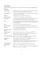
Specifications
Some specifications apply only if the corresponding option modules are installed (see Options, pg. 44).
GENERAL
Frequency Range
Main and Sub Receivers, 500 kHz - 30 MHz and 48-54 MHz. Transmitter: Amateur
bands between 1.8 and 54 MHz; transmit limits vary by country.
Tuning Step Sizes
1, 10, 20, and 50 Hz; user-configurable coarse tuning steps (per-mode). Direct keypad
frequency entry in either MHz or kHz
Memories
100ge
ne
r
a
lpur
pos
e
,pl
us4“qui
c
kme
mor
i
e
s
”per band
Frequency Stability
+/- 5 ppm (0-50 C) TCXO standard; +/- 1 ppm TCXO optional
Antenna Jacks
50 ohms nominal. One SO-239 supplied (2nd SO-239 jack supplied with KAT3 ATU).
BNC jacks for RX antenna in/out and transverter in/out (KXV3 Option).
Modes
USB, LSB, AM, FM, CW, and DATA. In DATA mode: FSK D (Direct), AFSK A
(Audio), PSK D (Direct) and DATA A (Audio; PSK, etc.). Built in PSK, RTTY, and
CW text decode/display.
VFOs
Dual VFOs (A and B) with separate weighted tuning knobs
Remote Control Port
EIA-232 standard DE-9F; USB adapter option. Full control of all radio functions
Audio I/O
Line-level isolated TX/RX audio int
e
r
f
a
c
e(
s
t
er
e
oout
put
s
)
;f
r
ont(
1/
4”
)a
ndr
e
a
r(
1/
8”
)
stereo headphone jacks; stereo speaker jack
Low Level Transverter
Interface
0 dBm typ.; BNC connectors (KXV3 Option)
Buffered IF output
BNC connector (KXV3 Option); see pg. 38 for interface recommendations
Other I/O
Key/Keyer/Computer, Paddle, PTT In, and KEY Out. Band information output via
binary interface and AUXBUS on ACC connector.
Real-Time Clock/Cal endar
Accuracy: Approx. +/- 20 ppm (+/- 2 seconds/day). U.S. and E.U. date formats.
Battery: 3 V coin cell (see pg. 47 for replacement instructions).
Supply Voltage
/Current
13.8 V nominal (11 V min, 15 V max). 17-22 A typical in TX for K3/100, 3-4 A
typical in TX for K3/10. 0.9A typical RX (less sub receiver).
Recommended supply: 13.8VDC @ 25A, continuous duty for K3/100; 13.8VDC @
6A for K3/10. For best results, use the supplied 5 foot (1.53 m) power cable.
Accessory DC output
Switched, 0.5 A max; 13 V no-load, 12 V max load (@ Vsupply = 13.8 V)
Weight (K3/100)
Approx. 8.5 lbs. (3.8 kg). With KRX3 sub receiver option, 9.5 lbs. (4.3 kg).
Size
Enclosure only, 4.0 x 10.7 x 10.0 in., HWD (10.2 x 27.2 x 25.4 cm); with projections,
4.4 x 11.1 x 11.8 in. (11.2 x 28.2 x 30.0 cm)
8
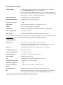
RECEIVER (Main and Sub)*
Sensitivity (MDS)
-136 dBm (typ.), preamp on, 500 Hz b/w. Reduced sensitivity near 8.2 MHz (first
I.F.). 6 m MDS with PR6 option: -143 to -144 dBm (typ.).
KBPF3 option required for full general-coverage receive, including broadcast band
(0.5 to 1.7 MHz). Note: Sensitivity gradually decreas es below 1.8 MHz due to highpass response of T-R switch. This protects the PIN diodes.
IMD3 Dynamic Range
> 100 dB typical at 5, 10, and 20 kHz spacing.
Blocking Dynamic Range
140 dB typical at 5, 10, and 20 kHz spacing
Image and I.F. Rejection
> 70 dB
Audio Output
2.5 W per channel into 4 ohms; typ. 10% THD @ 1 kHz, 2 W
S-Meter
Nom. S9 = 50 µV, preamp on; user-adjustable
Noise Blanker
Adjustable, multi-threshold/multi-width hardware blanker plus DSP blanker
Receive AF graphic EQ
+/- 16 dB/octave, 8 bands
Filter Controls
IF Shift/Width & Lo/High Cut with automatic crystal filter selection
* Dynamic range measurements based on 400-Hz, 8-pole filter. Other available filters have very similar performance; see
www.elecraft.com for full list. Receive specifications are guaranteed only within ham bands.
TRANSMITTER *
Output Power
K3/100: 0.1 W –100 W typ. (reduced power in AM mode).
K3/10 (or K3/100 with PA bypassed): 0.1 W –12 W, HF-10 m; 8W max on 6 m.
XVTR OUT (KXV3 option): 0.1 to 1.5 mW (-10 to +1.8 dBm).
Duty Cycle
CW and SSB modes, 100% 10-min. 100W key-down at 25 C ambient
True RF Speech Processor
Adjustable compression
Transmit AF graphic EQ
+/- 16 dB/octave, 8 bands
SSB TX Bandwidth
4 kHz max (> 2.8 kHz requires 6 kHz AM filter)
SSB TX Monitor
Post-DSP filtering/processing
VOX
DSP-controlled, adjustable threshold, delay, and anti-VOX
Full and Semi CW Break-In
Adjustable delay; diode T/R Switching
SSB Carrier Suppression
> 50 dB
Harmonic and Spurious
Outputs
> 50 dB below carrier @ 100W (> 60 dB on 6 meters)
CW Offset/Sidetone
300-800 Hz, adjustable (filter center frequency tracks sidetone pitch)
Mic
Front panel 8 pin mic connector; rear panel 3.5 mm mic connector. Switchable DC
bias voltage available for elect ret mics (see MAIN:MIC SEL menu entry)
* Transmit spe cifications are guarantee d only within ham bands.
9
Customer Service and Support
Technical Assistance
You can send e-mail to k3support@ele craft.com and we will respond quickly –typically the same day
Monday through Friday. If you need replacement parts, send an e-mail to [email protected]. T elephone
assistance is available from 9 A.M. to 5 P.M. Pacific time (weekdays only) at 831-662-8345. Please use e-mail
rather than calling when possible since this gives us a written record of the details of your problem and allows us
to handle a larger number of requests each day.
Repair / Alignment Service
If necessary, you may return your Elecraft product to us for repair or alignment. (Note: We offer unlimited email
and phone support, so please try that route first as we can usually help you find the problem quickly.)
IMPO RTANT: You must contact Ele craft before mailing your product to obtain authorization for the
return, what address to ship it to and current information on repair fees and turn around times. (Frequently we
can determine the cause of your problem and save you the trouble of shipping it back to us.) Our repair location
is different from our factory location in Aptos. We will give you the address to ship your kit to at the time of
repair authorization. Packages shipped to Aptos without authorization will incur an additional shipping charge
for reshipment from Aptos to our repair depot.
Elecraft 1-Year Limited Warranty
This warranty is effective as of the date of first consumer purchase. It covers both our kits and fully
assembled products. For kits, before requesting warranty service, you should fully complete the assembly,
carefully following all instructions in the manual.
What is cove re d: During the first year after date of purchase (or if shipped from factory, date product is
shipped to customer), Elecraft will replace defective or missing parts free of charge (post-paid). We will
also correct any malfunction to kits or assembled units caused by defective parts and materials. Purchaser
pays inbound shipping to us for warranty repair, we pay shipping to return the repaired equipment to you
by UPS ground service or equivalent to the continental USA and Canada. Alaska, Hawaii and outside U.S.
and Canada actual return shipping cost paid by owner.
What is not cove re d: T his warranty does not cover correction of kit assembly errors. It also does not
cover misalignment; repair of damage caused by misuse, negligence, or builder modifications; or any
performance malfunctions involving non-Elecraft accessory equipment. The use of acid-core solder, watersoluble flux solder, or any corrosive or conductive flux or solvent will void this warranty in its entirety.
Also not covered is reimbursement for loss of use, inconvenience, customer assembly or alignment time,
or cost of unauthorized service.
Limitation of incidental or conse quential damages: This warranty does not extend to non-Elecraft
equipment or components used in conjunction with our products. Any such repair or replacement is the
responsibility of the customer. Elecraft will not be liable for any special, indirect, incidental or
consequential damages, including but not limited to any loss of business or profits.
10
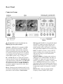
Front Panel
This reference section describes all front panel controls, the liquid crystal display (LCD), LEDs, and connectors.
Operating instructions are covered in later sections.
Control Groups
Primary Controls (pg 13): These controls
provide basic transceiver setup, including power
on/off, band, operating mode, AF and RF gain and
squelch, AT U and transmit controls, display modes,
and menus.
Ke ypad (pg. 15): This group of switches is
numbered for use during memory store/recall and
direct frequency entry, but each switch also has
normal tap and hold functions. T he upper row of
switches are VFO controls. The remaining rows
control receive-mode and miscellaneous functions,
such as noise reduction and text decode/display.
Display (pg 12): The LCD shows signal levels,
VFO A and B frequencies, filter bandwidth,
operating mode, and the status of many controls.
The VFO B display is alphanumeric, so it can show
decoded text from digital modes (CW, RTT Y,
PSK31), as well as menus, time and date, help
messages, etc.
Memories (pg. 16): These switches control
frequency memory store/recall, message
record/play, and audio record/playback (with the
DVR). M1 - M4 can also be used as up to eight
tap/hold programmable function switches.
Multi-Function Controls (pg. 14): T he upper two
knobs set up receiver DSP filtering. The lower two
control transmit parameters, including keyer speed,
mic gain, speech compression, and power output
level. LEDs above each knob show which function
is active; tapping the knob alternates between them.
Pressing and holding these knobs (1/2 second or
longer) provides access to secondary functions.
VFOs (pg. 14): The large knob controls VFO A;
the smaller knob controls VFO B. The four
switches between the VFO knobs select tuning rates
and control related functions.
RIT/XIT (pg. 16): Three switches control RIT and
XIT on/off and clear (offset zero). The knob below
the RI T / X I T switches selects the offset.
11
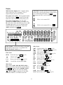
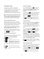
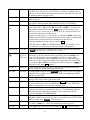
Display
Multi-characte r displays: The 7-segment display
(upper) shows the VFO A frequency. T he 13segment display (lower) shows VFO B.
VFO Icons: The TX icon and two arrows indicate
which VFO is selected for transmit as shown below.
In T XT EST mode, TX flashes (see TE S T ).
Shows that VFO A or B is locked (see L O CK ).
Bar graph, re ceive mode : The bar graph normally
acts as an S-meter. If CW T is turned on, the right
half of the S-meter becomes a tuning aid (pg. 34).
A
VFO A is the transmit VFO
Bar graph, transmit mode: The bar graph
normally shows S WR and RF power output. T he
RF scale will be either 5 and 1 0 (low power) or 50
and 1 00 (high power). In voice and data modes,
transmit scales can be changed to compression
( CM P ) and ALC using ME TE R .
TX
Filte r Graphic: T his shows the approx. bandwidth
a
ndpos
i
t
i
o
noft
her
e
c
e
i
ve
r
’
sI
.
F.p
a
s
s
b
a
nd. See
Filte r PassbandControls, pg. 23.
Othe r Icons:
TX
VFO B is the transmit VFO; see SPLIT
B
CW/data tuning aid on ( CW T , pg. 34)
DVR in use ( AF R E C / AF P L AY, pg. 16)
V O X VOX enabled ( V O X , pg. 13)
Q S K Full break-in CW enabled ( Q SK , pg. 30)
NB
Noise blanker on ( N B , pg. 15)
NR
Noise reduction on ( NR , pg. 15)
AN T Antenna 1 or 2 ( AN T , pg. 13)
RX
RX antenna in use ( R X AN T , pg. 13)
ATT Attenuator on ( AT T , pg. 15)
P RE Preamp on ( PR E , pg. 15)
ATU AT U enabled ( ATU , pg. 13)
RI T
RIT on ( R I T , pg. 16)
XIT
XIT on ( X I T , pg. 16)
S UB Sub receiver on ( S UB , pg. 37)
S P LT Split mode in effect ( S P LI T , pg. 36)
CW T
Filte r Icons:
NTCH
Notch filtering on ( N TCH , pg. 25)
Manual notch ( MAN , pg. 25)
I / II
Shows selected preset (I /I I , pg. 14)
XFIL
Crystal filter selection ( FL1 - FL5 )
Mode Icons:
Basic modes ( LS B / US B , CW , DATA , AM , or
FM ) are selected by tapping either end (Up/Down)
of MO D E . Alternate modes ( CW RE V , DATA
RE V , AM -S , FM + / - ) are selected by holding
AL T . LS B and US B are alternates of each other.
T indicates FM/tone, or CW/data text decode.
12
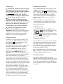
LEDs
Primary Controls
TX [Re d] T urns on in transmit mode.
B AN D T ap the left / right end of this switch to
move to the next lower / higher ham band.
V O X Selects voice-operated or keying-activated
(CW) transmit ( V OX icon on), or PTT-controlled
transmit. Also see
D EL AY (pg. 30).
∆F [Yellow] The Delta-F LED turns on if
transmit and receive frequencies or modes are
different due to the use of SPLIT, RIT, or XIT.
[Green] Eight LEDs show which functions are
in effect for the Multifunction Controls (pg. 14).
Selects either full break-in ( QS K icon on) or
semi break-in keying, if VOX is selected in CW
mode. Also see
D E L AY (pg.30).
QSK
(+ ) RIT/XIT O FFSET If the
offset control is centered, or you tap C LR , the
green LED turns on (offset = 0). Otherwise, the
yellow (-) or (+) LED will be on, indicating the
direction of the offset. See RI T , XI T , and C LR .
(-)
MO D E T ap the left or right end of this switch to
select the operating mode. When DATA is selected,
the D AT A MD switch is used to specify DATA-A,
AFSK A, FSK D, or PSK D (pg. 31).
In LS B mode, switches to US B (and viceversa). Also selects alternate modes, including:
CW RE V , DATA RE V , and AM -S (pg. 29). In
FM mode, selects + /- or simplex (pg. 29).
AL T
Front Panel Connectors
PHO NES You can use either mono or stereo
headphones at either the front- or rear-panel
headphone jack. Also see AF X (pg. 35).
Selects T X NORM or T X TEST ( TX LCD
icon flashing). T X TEST allows you to test keying,
mic level, etc., without actually transmitting.
TE S T
MIC An Elecraft MH2, MD2, Proset-K2, or other
compatible mic can be used (see pinout below). T o
select the front- or rear-panel mic, and to turn bias
on/off, use the MAIN:MIC SRC menu entry.
Bias must be turned on for electret mics (e.g. MH2,
MD2, Proset). It must be off for dynamic mics (e.g.
Heil mics using HC4 or HC5 elements).
T urns the K3 on or off. Note : To ensure
corre ct save of ope rating parame te rs, turn the
K3 off before turning the powe r supply off.
POW ER
ME N U
Displays MAIN menu (pg. 21).
C O NF I G
Displays the CONFIG menu (pg. 21).
Manually-operated transmit. Places the K3
into transmit mode (same as PTT, pg. 26).
X MI T
Puts out a carrier at the present power level.
Also TUNE Powe r Le vel (pg. 27).
TU N E
R X AN T
Selects the receive antenna (pg. 22).
D I S P Shows an alternate display on VFO B,
including time, date, voltage, etc. Use the VFO B
knob to select the desired display (pg. 36).
ME TE R Selects voice transmit bar graph modes:
S WR and RF , or CM P and ALC (pg. 28).
Mic jack, viewed from front of K3
1 Mic audio, low-Z (~600 ohms)
2 PTT
3 DOWN button *
4 UP button *
5 FUNCTION button *
6 8V (10 mA max)
7, 8 Ground
ATU TU N E Places the K3 into low-power CW
transmit mode and matches the antenna using the
KAT3 automatic antenna tuner (pg. 22).
Puts the ATU into normal mode ( ATU icon
on) or bypass mode (pg. 22).
ATU
* See CONFIG:MIC BTN menu entry (pg. 52)
AN T Selects ANT 1 or 2 and recalls the last ATU
settings used for that antenna (saved per-band). In
BSET mode with the sub receiver on, selects M AI N
or AUX antenna for the sub receiver (pg. 37).
FP ACC This connector (RJ-45, 6 pins) is located
on the bottom of the transceiver, near the VFO B
knob. It is used with accessory devices.
13
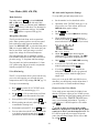
Dual-Concentric Potentiometers
Transmit Controls
AF — SUB AF gain controls for main
receiver (inner, or smaller knob) and sub receiver
(outer ring, or larger knob).
The primary functions of the transmit controls are:
SPEED
MI C
RF / SQL — SUB RF gain (and/or squelch)
controls for main and sub receiver.
C MP
PW R
T wo menu entries are provided to control squelch
directly: CONFIG:SQ MAIN, and SQ SUB. They
can also be used to reconfigure the RF gain controls
as squelch for either receiver. See the Config Menu
listing for details (pg. 52).
Keyer speed in WPM, 8-50
Mic gain
Speech compression level
RF output power in watts (pg. 26)
The present transmit mode determines which
primary functions normally apply; for example, in
CW mode, the
S P E E D / MI C control defaults to
S P E E D . You can always tap a knob to override
the present selection.
The secondary functions of these controls are:
Multi-Function Controls
D E L AY
The upper two multi-function controls set up
receiver filtering. The lower two controls adjust
transmit settings. Each control has two primary
functions (white labels) and a secondary function
(yellow). Tap a control knob to alternate between
its primary functions, indicated by two LEDs. Hold
a knob (~1/2 second or longer) to select its
secondary function.
MO N
VFO Tuning Controls
The VFO A knob controls the upper frequency
display. This is normally the RX and T X frequency.
In SPLIT mode, VFO B controls the transmit
frequency (pg. 36). VFO B also controls the sub
receiver when it is installed and turned on (pg. 37).
Filter Controls
The primary functions of the filter controls are:
S H IF T
LO CUT
H I CU T
W ID TH
VOX delay (voice/data) or CW semibreak-in delay, in seconds
Voice or data monitor level or
CW/data sidetone level
The controls to the right of VFO A include:
Shift passband either direction
Adjust low-frequency response
Adjust high-frequency response
Adjust width of the passband
F R EQ EN T
Direct frequency entry (pg. 15)
S C AN
Start or stop scanning (pg. 39)
Select 1 Hz tuning for both VFOs
and RIT /XIT offset
C O AR S E Select coarse tuning rate (pg. 22)
F IN E
As these settings change, so does the filter graphic.
Crystal filters are selected automatically (or
manually using X FI L , pg. 15). Also see Filter
Passband Controls (pg. 23).
R ATE
Select one of two normaltuning rates
(10/50 or 10/20 Hz; pg. 22)
L O CK
Lock VFO A (use B S E T to lock B)
SU B
T urn sub receiver on/off (pg. 37).
Hold this switch to link/unlink VFO A
and B on the present band (pg. 37)
The secondary functions of these controls are:
N OR M
Normalize passband
Normalizing the passband sets the bandwidth to a
fixed, per-mode value (e.g. 400 Hz in CW mode)
and centers the passband. (Also see user-defined
normal settings, NO RM1 /2 , pg. 24.)
I / II
VFO A can optionally be coarse-tuned using
the RIT /XIT offset control if both RI T and XI T are
off . See CONFIG:VFO OFS.
Select preset I or II (per mode)
Presets I and II each hold a continuously-updated
DSP/crystal filter setup (pg. 24).
14
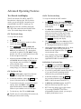
Direct Frequency Entry
Receiver Control & Misc. (Lower Rows)
To jump to any frequency within the tuning range
of the K3, tap FR E Q EN T , then enter 1 to 3 MHz
digits, a decimal point, and 0 to 3 kHz digits.
Follow this with Enter ( . . ) to accept or
F R E Q EN T to cancel. The decimal point is
optional if no kHz digits are entered, making it very
easy to get to the low end of most ham bands.
Receiver control functions normally apply to
VFO A. If BS E T is in effect, they apply to VFO B
and the sub receiver (if turned on).
Examples:
1.825 MHz: F R E Q E N T 1 . 8 2 5 .
1.000 MHz: F R E Q E N T 1
50.100 MHz: FR E Q EN T
.
.
PR E
Preamp on/off (6 m: see PR6, pg. 44)
ATT
Attenuator on/off
AG C
AGC slo w/fast
OF F
AGC off/on
XF I L
Select next available crystal filter
(see CONFIG:FLx ON)
D U AL P B
Dual-passband CW or dual-tone
RTT Y filtering (pg. 30)
NB
Noise blanker on/off (pg. 25)
L EVEL
Noise blanker levels (pg. 25); use
VFO A knob to setup DSP blanker,
and VFO B to setup I.F. blanker
NR
Noise reduction on/off (pg. 25)
AD J
Noise reduction parameter adjust; use
VFO B knob (pg. 25)
.
5 0 . 1
.
If four or more digits are entered without a
decimal point, a value in kHz is assumed.
Keypad
Each keypad switch has tap and hold functions,
listed below. These switches are also used for direct
frequency entry; to select quick memories 0-9; and
for selecting fields in certain menu entries, such as
time, date, filter, and transverter setup.
N TC H
Notch filter auto/manual/off (pg. 25)
VFO Controls (Upper row)
M AN
The upper row of numeric keypad switches is used
to set up VFOs A and B. Their functions are:
Manual notch frequency (pg. 25); use
VFO B knob
SPOT
Spot tone on/off (manual), or autospot (if CWT is on; pg. 34)
P I TC H
CW sidetone PI TCH , PSK center
pitch, FSK / AFSK MARK tone and
shift (pg. 31), or FM tone setup (pg.
29)
CWT
CW/data tuning aid on/off (pg. 34);
turn on to use auto-spot
TE X T D E C
Te xt de code, CW or DAT A (pg. 33);
use VFO B knob to select mode
AF X
Audio effects on/off (pg. 35); use
CONFIG:AFX MD to set mode
D AT A MD
DAT A mode selection (pg. 31); use
VFO B knob
A/ B
Exchange VFO A and B contents
B SET
Set up VFO B and sub receiver
R EV
Exchange VFO A and B temporarily
A
B
SPL I T
Copy VFO A to VFO B (also see
CONFIG:VFO B->A)
Enable SPLIT receive/transmit
Holding B S E T allows VFO B (and the sub
receiver, if on) to be set up directly (pg. 37). As
long as BS E T is displayed, all VFO-related
controls and display elements apply to VFO B. An
alternative is to set up VFO A, then A B .
15
Memory Controls
Digital Voice/Audio Recorder
Frequency Memories
T wo switches are dedicated to the DVR (KDVR3
option).
The K3 has 100 general-purpose memories (00-99),
plus up to 80 per-band memories (M1-M4 on each
of 11 regular bands and 9 transverter bands). Each
memory holds VFO A and B frequencies, modes,
filter presets, antenna selection, and other settings.
AF R E C
Start / stop audio record
AF P L AY
Start / stop audio playback
When record or playback is active, the
appears. It flashes during playback.
Memories can have a text label of up to 5 characters
(A-Z, 0-9, and various symbols). For example, you
might want to label memories associated with nets,
callsigns of broadcast stations, or your favorite
scanning ranges.
icon
The DVR is also used for message record and play
in voice modes (pg. 29).
Message Record/Play Controls
To store a gene ral-purpose memory ( 0 0 - 99 ):
First tap V M (VFO to Memory), then locate the
desired memory using the VFO A knob. The VFO
A frequencies stored in each memory will be shown
as you scroll through them. When you reach the
desired memory number, tap V M again to store,
or tap M V to cancel the operation.
Five switches provide record and playback of
outgoing messages: M1 , M2 , M3 , M4 and REC .
These switches provide single-tap play, hold-torepeat, and other functions that are convenient for
contests and for sending often-repeated text or
voice messages during QSOs.
To re call a gene ral-purpose memory: T ap
M
V , then select memory 0 0 - 9 9 using VFO A.
T ap M V again to confirm, or V M to cancel.
For details on CW message record/play, see pg. 30.
The same messages can be used with CW-to-DAT A
(pg. 34). For voice message record/play, see Digital
Voice Re corde r (pg. 29).
Memories 00-09 are quick memories, accessible
with just two switch taps. These could be used to
get to a starting point in each of 10 ham bands.
Memories M1 –M4 are per-band quick memories.
For example, you might set up M1 f
o
re
a
c
hb
a
nd
’
s
CW segment, M2 for the SSB se gment, etc.
M1 through M4 can alternatively be used as tap
or hold programmable function switches (pg. 21).
RIT and XIT Controls
To store or recall quick memorie s: T ap V M
or M V as before, but instead of rotating VFO A,
tap 0 - 9 or M1 - M4 .
To e rase one or more me mories: While scrolling
through memories to save or recall, tap C LR . Not
applicable to per-band quick memories ( M1 - M4 ).
Toaddorc
ha
ng
eame
mor
y’
st
e
xtl
ab
e
l
: First tap
M
V , then select a memory ( 00 -9 9 ) using VFO
A. Next, rotate VFO B to select each label position
in turn as indicated by the flashing cursor. Use VFO
A to change characters. After editing, tap M V
again. (Labels can be edited at any time, including
when you initially store a memory using V M .)
RIT
RIT (receive incrementaltuning) on/off.
PF 1
Programmable function switch (pg. 21)
XI T
XIT (transmit incremental tuning) on/off.
PF 2
Programmable function switch (pg. 21)
C LR
Sets RIT /XIT offset to 0;tap again to
restore offset to previous value. Hold for 2
seconds to copy present RIT offset to VFO
A before clearing.
The RIT /XIT offset control sets the offset for RI T
and X I T . Three LEDs above the control show at a
glance whether an offset is in effect (pg. 11).
An aste risk (*) at the beginning of a label
designates a channel-hopping memory (pg. 39).
16
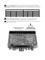
Rear Panel
Connector Groups
KIO 3 (pg. 18): T he KIO3 is an upgradeable digital
and audio I/O module providing computer and
auxiliary control signals, single or dual (stereo)
speaker outputs, line level in (mono) / out (stereo),
and supplemental headphone (stereo) and mic jacks.
The appearance of your rear panel may vary
depending upon the options installed.
Antennas: ANT1 (SO-239) is standard. ANT2
(SO-239) is supplied with the KAT3 automatic
antenna tuner option, which includes an antenna
switch controlled from the front panel. Both jacks
are nominally 50 ohms when the ATU is bypassed
or not installed. T he AUX RF connector is for use
with the KRX3 option; see pg. 37 and pg. 40.
KXV3: T he KXV3 provides a variety of RF I/O
signals, including receive antenna in/out (pg. 40),
transverter in/out (pg. 38), and a buffered I.F.
output (pg. 38).
Ke ying: PADDLE (
1/
4”p
ho
nej
a
c
k)i
st
hek
e
ye
r
paddle input (see CONFIG MENU, CW PDL, pg.
52). KEY (
1/
4”p
ho
nej
a
c
k)c
a
nb
eu
s
e
dwi
t
ha
hand key, external keyer, computer, or other keying
device. PTT IN (RCA/Phono) is for use with a
footswitch or other external transmit control device.
KEY O UT (RCA/Phono) is the amplifier T -R relay
keying output, capable of keying up to +200VDC
@ 5A.
DC: 12 VDC IN jack is an Anderson PowerPole
connector rated at 30 amps. (See Specifications, pg.
8, for detailed power requirements.) 12 VDC O UT
(RCA/Phono) provides up to 0.5 A (switched) for
use with accessory devices. Ground Te rminal: A
good station ground is important for safety and to
minimize local RFI.
KPA3: This option panel is blank in the K3/10. In
the K3/100, the blank panel is replaced with the fan
panel shown, which includes a circuit breake r.
REF IN (SMA): Input for external standard
frequency reference (KREF3-EXT option).
17
KIO3 Module
ACC (Accessory I/O)
The KIO3 provides serial I/O, control signals, audio
in/out for use with sound cards, speaker outputs,
and auxiliary headphone and mic jacks.
ACC connector pinouts are listed below.
ACC is not a VGA vide o conne ctor. The K3
doe s not provide video output.
RS232
The RS232 port can operate at up to 38,400 baud. A
straight-through cable is required.
Pin #
Description
I
fy
ou
’
r
eb
u
i
lding your own cable, you can use as
few as three wires (RXD, T XD, and ground; see
table below). DT R and RT S are optional.
1
FSK IN (see FSK Input)
2
AUXBUS IN/OUT (see KRC2 or XVSeries transverter instruction manual)
This table use s EIA standard descriptions,
which are from the pe rspe ctive of the PC. These
diffe r from K2 documentation, e ven though the
connections are functionally identical.
3
BAND1 OUT (see Band Outputs)
4
PTT IN (in parallel with MIC PTT)
5
Ground (RF isolated)
6
DIGOUT 0 (see Transve rte r Control)
7
K3 ON signal (out) or T X INH (in)
(see Transve rter Control, TX INH)
Not used
8
POWER ON (see pg. 43)
2
RXD IN (data to PC from K3)
9
BAND2 OUT (see Band Outputs)
3
T XD OUT (data to K3 from PC)
10
KEYOUT -LP (10 mA keying output)
4
DT R (see PTT and Ke ying, below)
11
DIGOUT 1 (see DIGOUT1)
5
Ground (RF isolated)
12
Ground (RF isolated)
7
RT S (see PTT and Ke ying, below)
13
BAND0 OUT (see Band Outputs)
14
BAND3 OUT (see Band Outputs)
15
EXT ALC input (see Exte rnal ALC,
pg. 27)
Pin #
1,6,8,9
Description
RS232 Conne ctor (female , on KIO3 panel)
Se rial Port Setup: Set CONFIG:RS232 for the
desired baud rate. Software should be set up at the
same rate; 8 data bits, no parity, 1 stop bit.
ACC Conne ctor (female, on KIO3 panel)
DTR and RTS: These are not used as serial I/O
handshaking lines. Instead, the K3 can use these as
PTT IN or KEY IN (see CONFIG:PTT-KEY). The
default for both signals is inactive. Refer to
application software documentation to determine if
it can use RS232 signal lines for PTT or keying.
FSK Input (for FSK D Data Mode)
This is a TTL input pulled up to 5V, compatible
with TTL-level PC outputs. When used with an
RS232 output signal from the PC, a level translator
is required (refer to your software manual).
If a PC or othe r de vice asse rts RTS or DTR
while yo
u’
r
ei
nt
hePTT-KEY menu entry, the K3
will enter TEST mode as a pre caution.
DIGO UT 1
DIGOUT 1 is a per-band/per-antenna open-drain
output for controlling antenna switches, preamps,
filters, etc. See CONFIG:DIGOUT1.
18
Band Outputs (BAND0-BAND3)
BAND0-3 provide band selection signals. Their
behavior is determined by the CONFIG:KIO3
menu entry. (See tables below.)
With CONFIG:KIO3 set to HF-TRN , the
BAND0-3 outputs follow the NO R table when HF6 m bands are selected, and the TRN table when a
transverter band is selected.
BAND0-3 are open-drain outputs. The attached
device must provide pull-up resistors (typ. 2.2K) to
its own supply voltage (usual 5 VDC).
Transve rte r Control
In the tables below, 0 = 0 VDC, and 1 = device
supply voltage.
Normally, when the K3 is turned on, a 5-VDC logic
signal appears on ACC pin 7 (K3 ON). T his could
be used with Elecraft XV transverters as an enable
signal (pin 8 of J6 on the transverter).
With CONFIG:KIO3 se t to NO R , the BAND0-3
outputs are mapped based on the selected HF-6 m
band as shown below. This mapping matches that
of some third-party band decoders. On Transverter
bands, BAND0-3 will all be set to zero.
Band
160 m
80 m
60 m
40 m
30 m
20 m
17 m
15 m
12 m
10 m
6m
BAND3 BAND2
0
0
0
0
0
0
0
0
0
1
0
1
0
1
0
1
1
0
1
0
1
0
However, pin 7 can alternatively be configured as a
transmit inhibit input line for use in multitransmitter stations. (See TX INH, below.) In this
case it is not available as a power-on signal for
El
e
c
r
a
f
tt
r
a
ns
ve
r
t
e
r
s
.
I
ns
t
e
a
d
,
t
heK3’
s12-VDC
switched output line could be used.
BAND1 BAND0
0
1
1
0
0
0
1
1
0
0
0
1
1
0
1
1
0
0
0
1
1
0
For transverter keying, you can use KEYOUT -LP
signal (pin 10 of the ACC connector) or the KEY
OUT jack (RCA).
With KIO3 set to TRN or HF-TRN , the DIGOUT 0
line (ACC, pin 6) will output 0 V when low power
mode is selected for the current transverter band
(CONFIG:XVn PWR). At all other times,
DIGOUT 0 will be floating (Hi-Z).
TheK3
’
sBAND0-2 outputs emulate the
El
e
c
r
a
f
tK60
XV’
sXVTR0-2 signals when
CONFIG:KIO3 is set to TRN or HF-TRN .
However, BAND0-2 on the K3 are open-drain
signals, while XVT R0-2 on the K60XV are TTL.
If CONFIG:KIO3 is set to TRN , BAND0-3 reflect
the parameters of CONFIG:XVn ADR as shown
below. On HF-6mt
he
y
’
r
es
e
tt
o0
.
ADR
T R N1
T R N2
T R N3
T R N4
T R N5
T R N6
T R N7
T R N8
T R N9
TX INH ( Transmit Inhibit Signal)
BAND3 BAND2
0
0
0
0
0
0
0
1
0
1
0
1
0
1
1
0
1
0
BAND1 BAND0
0
1
1
0
1
1
0
0
0
1
1
0
1
1
0
0
0
1
Pin 7 of the ACC connector can be configured as a
transmit inhibit input by setting CONFIG:TX INH
to LO = I nh (or HI = I nh ). Holding pin 7 low (or
high) will then prevent transmit. An external 2.2 to
10 K pull-up resistor (to 5 VDC) is required.
If TX INH is set to O FF, pin 7 reverts to its
default output function, K3 ON (see above).
Ele craft KRC2 Unive rsal Band De code r
An Elecraft KRC2 can be used with the K3 to
perform station switching functions; it includes sink
and source drivers for all bands. The KRC2 uses the
AUXBUS rather BAND0-3 (see CONFIG:KRC2
for 6-meter band mapping). Refer to the KRC2
instruction manual for more information.
19
SPKRS
LINE IN
ST EREO or MONO; 4 to 8 Ω
MONO, transformer-isolated; 600 Ω(
n
omi
na
l
)
Plugging in external speaker(s) cuts off the internal
speaker. A stereo plug is recommended; tip is left
speaker, ring is right. If you only have a mono plug,
set CONFIG:SPKRS to 1 to disable right-channel
audio. (Also see important note below.)
This i
n
pu
ts
hou
l
db
ec
on
ne
c
t
e
dt
oyou
rc
o
mpu
t
e
r
’
s
soundcard output. The MI C gain control sets the
line input level when the MAIN:MIC SEL menu
entry is set to LI NE I N .
The LIN IN le vel should be se t carefully to
avoid transmit signal distortion due to
s
a
t
ur
at
i
o
no
ft
heK3’
si
nputaud
i
ot
r
a
ns
f
o
r
me
r
.
In addition, sound card gain should be set 6 to 10
dBb
e
l
owt
hel
ev
e
latwhi
c
ht
hes
o
undc
ar
d’
s
output stage starts clipping.
PHONES
ST EREO or MONO; 16 Ωmi
n
.r
e
c
omme
nd
e
d
The front and rear-panel headphone jacks are both
isolated with series resistors. This allows you to use
mono phones on one jack and stereo on the other, if
r
e
q
u
i
r
e
d
.You
’
l
lne
ed stereo phones for AFX (audio
effects) and stereo dual receive (with sub receiver).
LINE OUT
ST EREO, transformer-isolated; 600 Ω(
n
omi
na
l
)
The
s
eou
t
pu
t
sc
a
nb
ec
o
nne
c
t
e
dt
oyou
rc
ompu
t
e
r
’
s
soundcard inputs. Normally, the left channel is
main receiver audio, and the right channel is sub
receiver audio (if applicable). In this case the
outputs are post-AGC but pre-AF-gain.)
You can plug in headphones and speaker(s) at
the same time, and hear audio in both, if you set
CONFIG:SPKR+PH to Y ES . However, if you set
CONFIG:SPKRS to 1 , setting SPKR+PH to YE S
will force mono headphone as well as speaker
output. You can set SPKRS to 2 if you use a stereo
plug at the external speaker jack, or if no external
speaker is plugged in.
Use CONFIG:LIN OUT to set the level, or to
switch from a fixed-level setting to = P HO NE S .
LIN O UT settings above 10 are usually not
ne cessary, and can in some cases cause
ov
er
l
oad
i
ngof
e
i
t
hert
heK3’
so
ut
p
ut
transformers or the PC soundcard inputs
(typically on noise peaks). Eithe r could degrade
the pe rformance of digital demodulation
software .
MIC
MONO; hi- or low-Z
This jack accommodates an electret or dynamic
mic. Use MAIN:MIC SEL to select the rear panel
mic ( RP). T ap 1 to turn on Low or High mic gain
range. T ap 2 to turn bias on/off (see pg. 28 for
recommendations based on mic type). Themi
c
’
s
PTT signal, if used, must be routed to either the
PTT IN jack or the PTT line on the ACC connector
(pg. 18).
Some laptop compute rs have only ve ry highgain, high-impe dance mic inputs, not line-le vel
inputs. This can make it difficult to adjust the
K3’
sLI
NEOUTle vel, and can also worsen noise
pickup. If your laptop has only a mic input, you
may want to add a resistive attenuator between the
K3 and the laptop to keep the signal-to-noise level
high.
20
Basic Operation
MAIN Me nu
T ap ME NU to access the main menu. (Tapping
ME N U again exits the menu.)
This section covers the fundamentals of K3 receive
a
ndt
r
a
ns
mi
to
pe
r
a
t
i
on.
I
t
’
l
la
l
s
og
e
ty
ous
t
a
r
t
e
d
using each of the major operating modes.
Use VFO B to scroll through the menu entries,
referring to the list on pg. 51 for details.
Onc
eyou
’
r
ef
a
mi
l
i
a
rwi
t
ht
heK3,
pl
e
a
s
eg
oo
nt
o
Advance d Ope rating Fe atures (pg. 33).
Change the value (or parameter) of any menu
entry using VFO A.
Using Tap/Hold Switches
CONFIG Menu
Most K3 switches have two functions. Tapping
(pressing for less than 1/2 second) activates the
function labeled on the switch. Holding (pressing
for more than 1/2 sec.) activates the function
labeled beneath the switch.
Hold C O NF I G (hold function of the ME NU
switch) to access the CONFIG menu.
Use VFO B to scroll through the CONFIG
menu entries, referring to the list on pg. 52.
Initial Power-Up
Menu Help
Connect a power supply (pg. 8); antenna or
dummy load; key, if used (pg. 16); mic, if used,
and station ground (pg. 16).
T ap D I S P to show help information about the
present menu entry. For most entries, the default
parameter value is shown in parentheses at the start
of the help text.
T ap P OW E R to turn the K3 on. The LCD
should illuminate and show VFO A/B
frequencies. (Tapping P O W ER again turns
power off.)
Programmable Functions
Menu entri
e
st
ha
tyou
’
dl
i
keq
u
i
c
ka
c
c
e
s
st
oc
a
nb
e
assigned to any of the 10 programmable function
switches, P F 1 , P F 2 , and M1 –M4 (tap or hold).
Func ti on menu entries can only be used via such
a switch assignment. (Examples, from the CONFIG
menu: VFO B->A and TTY LTR.)
The VFO B display can show a variety of
useful parameters in addition to the normal
frequency display. To see these, tap DI S P (left
of the display), then rotate the VFO B knob.
The VFO B display will cycle through time ,
date , RIT/XIT offset, supply voltage , current
drain, etc. (pg. 36). You can use these displays
to make sure the supply voltage is in range (1115 V), and that current drain is about 1 amp
(higher with sub receiver installed and turned
on). T ap DI S P to return to the normal VFO B
frequency display.
To set up a programmable function switch, first use
ME N U or C ON FI G to locate the target menu entry.
Next, hold P F 1 or P F 2 ; or, tap or hold M1 –M4 .
For example, if you tap M2 ,
you
’
l
ls
e
eM2 T S E T
(T for tap), while holding M2 would show M 2 H
S E T (H for hold). The assigned switch can then be
used as a shortcut to access that entry. M1 –M4 can
each be assigned a tap and/or hold programmable
function.
Using the Menus
Any M1 –M4 switch that is used as a
programmable function switch will not be available
for message play. To cancel a programmable switch
assignment and restore a previously-saved message,
tap R EC ,
t
he
nt
a
pt
heb
u
f
f
e
ry
ou
’
dl
i
ket
or
e
s
t
o
r
e
( M1 –M4 ), then tap R E C again.
There are two menus: M AI N and CO NFI G . Most
entries in the CONFIG menu are used for test,
configuration, and alignment, and are used
infrequently.
Nearly all menu entries appear in alphanumeric
order. In the few exceptions to this, adjacent entries
are still closely related.
21
Band and Mode Selection
Using the VFOs
T ap either end of the B AN D switch to select the
desired ham band (160 through 6 meters). You can
also go directly to any desired frequency using
direct frequency entry (pg. 15), or recall a
frequency memory (pg. 16).
VFO A is both the main receive and transmit
frequency, except during SPLIT, in which case
VFO B controls the transmit frequency (pg.36).
VFO B also controls the sub receiver (pg. 37).
T ap R ATE to select 10 / 50 Hz per step. The faster
rate can be changed using CONFIG:VFO FST.
The number of counts (or steps) per VFO knob turn
can be changed using CONFIG:VFO CTS.
T apping R ATE briefly flashes either the 10-Hz or
100-Hz digit to indicate slow or fast tuning.
T ap either end of MO D E to select the operating
mode. Hold AL T to select an alternate mode, if
required. This include CW RE V (pg. 30), DATA
RE V (pg. 31), AM -S (synchronous detection, pg.
29), and FM + / - (FM repeater split, pg. 29).
For 1-Hz steps, tap FI N E ; for wider steps, use
C O AR S E (see CONFIG:VFO CRS). When F IN E
is in effect, a 1-Hz digit will appear in the VFO A
display. When C O AR S E is in effect, the 10-Hz
digit is not shown.
Antenna Selection and Matching
ATU (KAT3)
If you have the KAT3 antenna tuner installed, you
can select ANT1 or ANT2 by tapping AN T .
T ap A B on
c
et
oc
o
pyVFOA’
sf
r
e
q
u
e
nc
yt
o
VFO B. T apping A B a second time within 2
s
e
c
ond
sa
l
s
oc
opi
e
sVFOA’
smod
e
,f
i
l
t
e
r
,a
ndo
t
he
r
settings to VFO B.
Hold ATU to select AUTO (autotune enabled) or
BY P AS S . If the ATU icon is on, the antenna can
be matched for best SWR by tapping ATU TU N E .
AT U settings are saved per-band and per-antenna.
exchanges VFO A and B and their settings.
(Also see CONFIG:VFO B->A.) Pressing R E V
A/ B
T apping ATU TU N E a second time within 5
seconds of a match attempt will retry using a more
extensive search. This may improve the match
when using high-SWR or narrow-band loads.
exchanges the VFOs for as long as you hold it in.
VFO B and the sub receiver can be set up directly
by holding B S E T . While BS E T is in effect, all
icons and VFO-related controls apply to VFO B
(and to the sub receiver, if turned on; see pg. 37).
Holding AN T allows names to be assigned to
a
n
t
e
n
na
s(
e
.
g
.
,
‘
Y AGI ’
). T hese will be flashed each
time you switch antennas. When editing names,
VFO B selects the character position to change;
VFO A cycles through available characters. Setting
t
h
ef
i
r
s
tc
ha
r
a
c
t
e
rt
o“—”d
i
s
a
b
l
e
sna
med
i
s
pl
a
y.
Holding S U B links/unlinks the VFOs, whether or
not a sub receiver is installed or turned on (pg. 37).
RIT and XIT
The RIT /XIT offset control, at the far right, sets the
offset for RI T and X I T . The offset is shown on the
VFO B display as you adjust the control. T hree
LEDs show whether the offset is 0, (-) or (+).
RX Antenna (KXV3)
With the KXV3 installed, you can tap R X to select
a receive-only antenna (RX ANT IN). The K3 also
has an RX ANT OUT jack for use with in-line
filters, the PR6 6-m preamp, etc.; see pg. 38.
T ap C LR to zero the RIT /XIT offset. Tapping it a
second time restores the offset.
To copy the present RIT offset to VFO A, hold
C LR for 2 seconds. VFO A will be moved to the
new frequency before the offset is zeroed.
Sub Re ceive r Antenna (KRX3)
If the sub receiver is turned on (by tapping S UB ),
its antenna selection can be changed using B S E T .
While in BSET , tap AN T to switch between M AI N
(sharing the main antenna) and AUX (using the
s
u
b
’
sAUXRFinput). For further details on sub
receiver antennas, see pg. 37 and pg. 40.
If RIT and XIT are both turned off, the RIT
offset can coarse-tune VFO A (CONFIG: VFO
CRS). For example, you can select 5, 9, or 10 kHz
steps in AM mode.
22
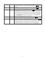
Receiver Setup
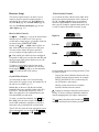
Filter Passband Controls
This section explains howto use basic receiver
controls. Setup for specific operating modes is
described in later sections; see Voice Modes (pg.
28), CW Mode (pg. 30), and Data Modes (pg. 31).
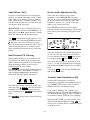
As you rotate the filter controls (shift, width, hicut,
locut), the associated parameter value is shown on
VFO B. T he filter graphic shows the width and
location of the passband, as illustrated below. In
these specific examples, segments that turned off as
a result of control movement are shown in gray.
Also see Text Decode and Display (pg. 30) and
Audio Effects (pg. 35).
Receiver Gain Controls
High Cut
Use
AF — S UB (pg. 11) to set the desired main
and sub receiver volume level. T here are two
overall audio volume ranges, LO and HI, which can
be selected using CONFIG:AF GAIN.
Low Cut
Usually, both RF — S UB controls will be set
fully clockwise (main and sub receiver RF gain).
You may wish to reduce RF gain to optimize
receiver response to high signal levels or noise.
Width
If the sub RF gain knob has been reconfigured
as squelch for both receivers, then the main RF gain
knob will control RF gain for both receivers. (See
CONFIG:SQ MAIN.)
Shift
To improve weak-signal reception, turn on the
preamp using P R E . In the presence of extremely
strong signals, you may wish to use the attenuator
( ATT ), or reduce the RF GAIN setting.
Each passband control has an integral switch. These
are used as follows:
Tapping the control alternates between the two
primary functions for that control, for example
HICUT and WIDT H. This is indicated by the
two LEDs above each control.
Crystal Filter Selection
You can install as many as five crystal roofing
f
i
l
t
e
r
si
nt
heK3’
sma
i
nr
e
c
e
i
ve
r
,a
nda
n
o
t
he
rf
i
vei
n
the sub receiver (KRX3, pg. 37).
Holding a control activates its secondary
function, labeled below the control.
Bandwidths as narrow as 200 Hz and variablebandwidth f
i
l
t
e
r
sa
r
ea
va
i
l
a
b
l
e
,
t
h
a
n
kst
ot
heK3’
s
low first I.F. (intermediate frequency) of 8.215
MHz. See Appendix A for recommended crystal
filter bandwidths for each mode.
T apping or rotating a control shows the present
setting. To see the settings of both knob functions
without changing them, just tap the control twice.
To select a crystal filter manually, tap X FI L . The
FL1 - FL5 icons show the current selection. This
sets the DSP passband to match the crystal filter,
and removes any passband shift or lowcut/hicut.
The secondary functions of the controls are N OR M
and I /I I , described in the following sections.
The K3 will also select the most appropriate crystal
filters automatically as you adjust the S H I F T ,
W ID TH ,
L O CU T , and
H I CU T controls.
23
Filter Presets (I/II)
Custom Settings (NO RM1 and NORM2)
Ea
c
hope
r
a
t
i
ngmod
ep
r
o
vi
d
e
st
wo‘
f
l
oa
t
i
ng
’f
i
l
t
e
r
prese ts, I and II, which store filter settings on a
per-VFO, per-mode basis (excluding FM). They are
updated continuously as you change filter settings.
(Fixed, per-mod
e‘
no
r
ma
l
’s
e
t
t
i
ng
sa
r
ea
l
s
o
available; see below.)
In addition to the K3's standard "NORM" values,
you can save two of your own setups in each mode,
then recall them using the N OR M function. These
setups are referred to as NORM1 and NORM2.
To save a custom normalization setting:
set up the filter passband as desired for the
current mode
You can alternate between the I and II settings by
holding I/ II .
Thi
si
se
s
pe
c
i
a
l
l
yu
s
e
f
u
lwhe
nyou
’
r
e
using wide and narrow settings during contest or
DX operation.
hold N OR M until you see < - S AV - > (3
seconds)
rotate the knob slightly left or right to save it as
NO RM 1 or NO RM 2 .
The I and II settings for VFOs A and B are
independent.
The arrows to the left and right of S AV are a
reminder that you can rotate the knob to get to the
two user-defined normalization settings.)
Filter Normalization (NORM)
Standard Settings
To recall, hold N OR M until you see < - NO R - >
(about 1/2 second), then rotate the knob left or right
to recall NO RM 1 or NO RM2 .
To get quickly to a standard per-mode bandwidth
and reset any passband shift or cut, hold N OR M
(normalize). The normalized bandwidth is 400 Hz
in CW and DAT A modes, 2.7 or 2.8 kHz in SSB
modes, and 6 kHz for AM.
Narrow DSP Filter Types
Forb
a
nd
wi
d
t
hs
e
t
t
i
ng
sof1
00Hzo
rl
owe
r
,
t
heK3’
s
DSP normally uses a type of filter that minimizes
ringing: the Finite Impulse Response or FIR filter.
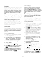
Whenever you normalize the filter passband,
two small "wings" appear at the left and right ends
of the DSP filter passband graphic as shown below.
I
fy
ou
’
dl
i
kes
t
e
e
pe
rf
i
l
t
e
rs
ki
r
t
s
,a
ndd
on’
tmi
nda
small amount of ringing, you can select Infinite
Impulse Re
s
po
ns
e
”o
rI
I
Rf
i
l
t
e
r
sf
ort
he
s
e
bandwidths. Locate CONFIG:FLx BW menu entry,
then tap 7 until you see I I R O N . Both main and
sub receivers will use the same setting.
Moving any DSP control makes the "wings"
disappear, as a reminder that the passband is no
longer normalized.
24
T he DSP noise blanke r is in the 2nd I.F., where
i
tc
a
n’
tb
ea
c
t
i
va
t
e
db
ys
i
g
na
l
sou
t
s
i
d
et
hec
r
ys
t
a
l
filter passband. It can be used with high-duty-cycle
and complex-waveform noise generated by
computers, switching power supplies, light
dimmers, etc. T he I.F. noise blanke r is in the 1st
I.F., where it can use very narrow blanking widths.
It is most effective at blanking AC line noise,
lightning, and other very broadband noise. Often, a
combination of the two is the most effective.
Reducing Interference and Noise
The K3 provides several ways to cut interference,
including DSP noise reduction, manual and auto
notch, and noise blanking. Also see Audio Effe cts
( AF X , pg. 35).
There are actually two noise blankers: one at the
first I.F. (KNB3 module), and the other at the 2nd
I.F. (DSP).
Noise reduction, noise blanking, and notch
filtering should only be used when necessary. T hese
signal processing techniques are extremely
effective, but can introduce side effects. Sometimes,
reducing the filter bandwidth is the most effective
interference-reduction strategy.
Noise Reduction
Noise reduction reduces random background noise
while preserving meaningful signals. It adds a
c
ha
r
a
c
t
e
r
i
s
t
i
c“h
ol
l
ow”s
ou
nd to all signals.
T ap N R to turn on noise reduction. NR is not
applicable in DAT A and FM modes, or with AGC
turned off.
Noise Blanking
First, tap N B to enable I.F. and/or DSP noise
blanking.
Hold AD J to display the NR setting; use the VFO
B knob to tailor NR for the present band conditions.
The settings are F1 -1 through F4 -4 . Higher
settings can degrade weak signals. T he first part of
the number ( Fx ) determines which NR algorithm is
used; F1 is the least-aggressive setting. The second
part ( -y ) controls how much of the signal is routed
through noise reduction, from 1 (50%) to 4 (100%).
Next, hold L E V E L to set the DSP level (VFO A)
a
ndI
.
F.l
e
ve
l
(
VFOB)
.You
’
l
li
ni
t
i
a
l
l
ys
e
eDS P
O FF and I F O FF on the VFO A and B displays.
Rotating VFO A clockwise will turn on the DSP
NB, showing DS P t1 -1 through DS P t3 -7 . The
first number shows the relative pulse integration
time, and the second shows the blanking level. The
higher the numbers, the more aggressive the DSP
blanking action.
Notch Filtering
Notch filtering removes interfering carriers while
leaving the desired signal relatively unaffected. The
K3 provides automatic and manual notch tuning.
Rotating VFO B clockwise will turn on the IF NB,
showing I F NARn , I F M E Dn , or I F WI Dn ,
where n is 1 -7 . NAR /M E D /WI D refers to narrow/
medium/wide blanking pulse widths, and n is the
blanking level. Higher n means more aggressive
blanking action. Use NAR width when possible to
minimize strong-signal interaction effects.
Auto notch will find and remove one carrier, and in
some cases more than one. It is only available in
SSB modes, and AGC must be turned on.
T he NB icon will flash slowly if the I.F.
blanker setting is too high for the present signal
conditions. If this happens, use a lower setting.
Manual notch removes one carrier at a specified
pitch, and can be used in CW and DAT A modes as
well as voice. Since manual notching sets up a fixed
(rather than adaptive) notch, it can even suppress a
keyed carrier, i.e. a CW signal.
Both the DSP and IF blanking settings are saved on
a per-band basis. If CONFIG:NB SAVE is set to
Y E S , the on/off status of NB will be also be saved
for each band.
T ap N TC H to turn on notch filtering ( NTCH icon).
This turns on Auto notch if applicable. T ap a
second time if necessary to select manual notch
(adds
icon). T ap again to turn notch off.
Hold MAN to adjust the manual notch frequency
using VFO B. This also selects manual notch.
25
Transmitter Setup
VOX, PTT, and QSK
In voice and data modes, use V O X to select VOX
(pg. 13) or PTT (push-to-talk). PTT can still be
used even with VOX selected. Set VOX gain and
anti-vox level using MAIN:VOX GN and
ANTIVOX.
Transmit Crystal Filter Considerations
For each operating mode, you must specify which
I.F. crystal filter to use for transmit using the
CONFIG:FLTX menu entry. See pg. 46 for
recommended per-mode transmit filter bandwidths.
In CW mode, use V O X to select either VOX or PTT
t
r
a
ns
mi
t
.VOXe
n
a
b
l
e
s“u
s
e
r
-a
c
t
i
va
t
e
d
”(
hi
t
-thekey) transmit, while PTT requires the use of PTT
IN (pg. 17) or X MI T before CW can be sent.
T ransmit signals are generated on the RF board,
so the set of filters installed on the RF board must
meet the transmit bandwidth requirements of all
modes you plan to use. (Filters installed on the sub
receiver board are used only in receive mode.)
When the V OX icon is on in CW mode, you can
use Q S K to select full ( Q S K icon on) or semi
break-in. For more on break-in keying, see pg. 30.
Transmit Status LED s and Icons
Transmit Metering
Before putting the K3 on the air, you should be
familiar with the LEDs and LCD icons that pertain
to transmit operation (identified on pgs. 11 and 12).
The most important of these are reviewed here.
Normally, the transmit bar graph shows S WR and
RF (power output). The displayed S WR range is
1:1 to 3:1. The RF control range is 0 to 12 W in
1-W units, or 0 to 120 W in 10-W units. The power
scale changes from watts x1 to watts x10 at 13
watts.
The TX LED turns on during transmit. The ∆F
(Delta-F) LED turns on if the transmit and receive
frequencies differ (SPLIT / RIT / XIT).
In voice modes, you can use ME TE R to switch to
compression ( CMP ) and automatic level control
( ALC ) metering. See pg. 28 for information on
adjusting the MI C and
C MP controls.
The TX LCD icon and associated arrows show
which VFO is being use d for transmit. If you plan
to use S P L I T mode, See pg. 36.
If you have a KXV3 installed, you can use
milliwatt-le vel power output. This is intended for
use with transverters, but it can also allow the K3 to
act as a very stable, very low-noise signal generator.
To route RX and T Xthrough the XVT R jacks on all
bands, set CONFIG:KXV3 to TE S T.
Multifunction Transmit Controls
There are two multifunction transmit controls. Their
primary functions (mode-dependent) are:
SPEED
MI C
C MP
PW R
CW keyer speed in WPM
Mic gain
When milliwatt-level output is in effect, rotating
P W R will show milliwatts on VFO A, and dBm
(dB relative to 1 milliwatt) on VFO B.
Speech compression level in dB
RF output power in watts (also see
Per-Band Powe r Control, pg. 27)
Off-Air Transmit Testing
The secondary (hold) functions of these controls
are:
D E L AY
VOX or CW semi-break-in delay
MO N
Voice/Data monitor or CW sidetone
level.
The K3 allows you to listen to your CW keying, test
your mic and compression settings, or monitor
DAT Atones, without transmitting an on-air signal.
To do this, hold TE S T (right end of the MO D E
control). While you're in TEST mode, the TX icon
will flash slowly as a reminder that you're off air.
Hold TE S T again to return to normal operation.
26
External ALC
Per-Band Power Control
Exte rnal ALC should only be use d to prote ct
your amplifie r during ope ration into a faile d
load, or during a prolonge d ove rdrive condition.
ALC should not be use d as a way to clip or
compress fast voice pe aks, or as a primary
me ans of amplifie r or K3 powe r output control.
If the CONFIG:PWR SET menu parameter is set
to NO R , power output on all bands follows the
present setting of
P W R . If you change PWR
SET to P E R-BAND , the power level will be saved
independently on each band. This is especially
useful with transverters and external amplifiers, or
for those who use QRP levels on one band and
QRO on another.
DO NOTs
e
tt
heK3’
spowe
rl
ev
elt
o
maximum and adjust amp output using the
amp
’
sALCc
o
nt
r
o
l
.Thi
swi
l
lr
e
s
ul
ti
ns
p
l
at
t
er
and key clicks. Instead, adjust the drive on each
bands
oi
t
’
sj
us
tb
e
l
owALC activation le vel.
When per-band power control is used with an
external amplifier, you can adjust the drive ideally
on each band to prevent external ALC activation
during normal operation.
Pre paring the K3 for use with Exte rnal ALC
TUNE Power Level
You may nee d to modify the K3 to use
exte rnal ALC, de pending on its date of
manufacture. Please refer to our K3 Modifications
web page. If you turn on external ALC without
making necessary modifications, power will be
reduced to a very low level during transmit.
If CONFIG:TUN PWR is set to NO R , power
output during TU N E will follow the present setting
of
P W R . If you change the TUN PWR
parameter to a fixed power level, that level will be
used during TU N E ,whe
t
he
rorn
oty
ou
’
ves
e
l
e
c
t
e
d
per-band power control (see above).
Exte rnal ALC Setup
Transmitter RF Delay
External ALC is set up using the CONFIG:EXT
ALC menu entry. EXT ALC defaults to O FF . To
turn it O N , tap 1 . 6 meter external ALC can be
turned on/off separately from HF.
Some amplifiers have slow relays whose switching
time must be accommodated to prevent key clicks
during CW operation. If your amplifier requires
more than 8 ms of relay switching time, you can
increase the delay from key-down to RF output at
the K3 using CONFIG:T X DLY.
The EXT ALC menu entry provides a default ALC
threshold of -4 . 0 V, used by many amplifiers.
If you select CMP /ALC metering at the K3,
external ALC activity is indicated by 8 or more
bars. If you select S WR /RF metering, the
CM P /ALC meter icons will flash during external
ALC activity to make you aware of the condition.
Use the smallest value of T X DLY that works
with your amplifier. Larger values will affect QSK
and keying timing at high code speeds.
Transmitter Inhibit
Some experimentation may be required to
d
e
t
e
r
mi
net
hepr
o
pe
rs
e
t
t
i
ngof
t
hea
mpl
i
f
i
e
r
’
sALC
output control, if one is provided. Start with the
control set for minimum ALC output. T hen adjust
t
h
eK3
’
sp
owe
rou
t
pu
ts
u
c
ht
ha
tt
hea
mpl
i
f
i
e
ri
sj
u
s
t
reaching its maximum level on voice peaks (in SSB
mode) or peak CW power in CW mode.
Some multi-transmitter stations require that
transmitters be able to mutually inhibit each other in
order to prevent simultaneous use of resources. The
K3 provides a transmit inhibit input (TX INH) that
can be programmed for low- or high-active control.
See pg. 19.
Ne
x
t
,a
d
j
u
s
tt
hea
mpl
i
f
i
e
r
’
sALCou
t
pu
tc
on
t
r
ol
upward until ALC action just begins (or adjust the
K3’
sALCt
hr
e
s
h
ol
dwi
t
ht
heEXT ALC menu
e
n
t
r
y
)
.Fi
na
l
l
y,
r
e
d
u
c
et
heK3’
sd
r
i
v
ep
owe
rj
u
s
t
slightly to provide some safety margin. The goal is
to have no amplifier ALC action during normal
operation. If you see an ALC indication at the K3 or
t
h
ea
mpl
i
f
i
e
r
,r
e
d
u
c
et
heK3
’
sp
owe
rou
t
pu
t
.
27
Voice Modes (SSB, AM, FM)
Mic Gain and Compression Settings
Mode Selection
To set up MIC gain and compression level:
T ap either end of MO D E to select LS B /US B ,
AM , or FM mode. Holding the left end of this
control, AL T , selects an alternate mode. LS B and
US B are alternates of each other. The alternate for
AM is AM -S (synchronous AM, pg. 29). In FM
mode, AL T enables a repeater offset (pg. 29).
Set the monitor level as described earlier.
Optionally select TX TEST mode (pg. 13) or
set power to zero. This will not affect your
CM P /ALC bar graph readings.
Set
C MP
to 0 .
Hold ME TE R to select CMP /ALC metering.
Microphone Selection
While speaking into the microphone in a
normal voice, adjust
MI C for a peak ALC
meter indication of about 5-7 bars (see below).
The K3 provides both front- and rear-panel mic
jacks. Some operators prefer to use the rear-panel
jack to minimize cable clutter around the front
panel. Use MAIN:MIC SEL to select the front panel
( FP ) or rear-panel ( RP ) jack. This menu entry can
also be used select a mic gain range, as well to
apply a bias voltage for electret microphones.
Adjust
C MP for the desired speech
compression level while speaking. T he CMP
scale shows approximate compression level.
The front-panel mic jack is compatible with the
Elecraft MH2, MD2, Proset-K2, and some other 8pin mics (see pg. 13 for pinout and bias settings).
Hold ME TE R to select S WR /P WR metering.
The rear-panel mic jack accommodates a 3.5-mm
(1/8") phone plug, and can be used in conjunction
with the rear-panel PTT IN jack.
If you were in TX T EST mode, return to
normal operation by holding TE S T .
Voice Monitoring
If you had
P W R set to 0, set it for the
desired level in watts. Key the rig again and
verify that you have about the right power
output level.
TheK3’
svoi
c
emo
ni
t
o
ra
l
l
owsyout
ohe
a
rt
hewa
y
your voice will sound at your selected mic gain,
compression, and T X EQ settings ( TX E Q , pg. 35).
Onc
eyou
’
veset up the MIC and CMP levels as
described, you should only need to adjust them if
you switch mics or if band conditions change.
To set up voice monitoring:
Power Level for Voice Modes
Hold TE S T to put the K3 in T X TEST mode,
s
oyouwon
’
tb
et
r
a
ns
mi
t
t
i
ng(
pg
.13).
Voice-mode power output may be slightly lower
than the CW power output you see in when you use
TU N E . Adjusting mic gain higher cannot correct for
this. Instead, use the CONFIG:TXG VCE menu
entry (voice transmit gain balance). Typically a
value of 0.0 to 1.5 dB will equalize voice modes
with TU N E .
Set
MI C to 15-3
0t
oe
ns
u
r
et
ha
tyou
’
l
l
he
a
r
your voice. You can fine-tune this level later.
Pr
e
s
syou
rmi
c
’
sPTTs
wi
t
c
hort
a
pX MI T .
While speaking into the mic, adjust
a comfortable listening level.
MO N
for
Exit transmit (release PTT, or tap X MI T again).
I
fy
o
u’
r
eus
i
ngan external peak-reading
wattmete r, adjust powe r such that spee ch peaks
remain at or below your de sire d powe r le vel. T he
K3’
sRFb
a
rg
r
a
p
hma
yno
tc
a
p
t
u
r
ea
l
ls
pe
e
c
h
peaks, but your actual output will be close to that
set with P W R .
You can either leave the K3 in T X TEST mode
or go back to normaltransmit (hold TE S T ) as
you follow the instructions in the next section.
28
Voice Mode VOX Setup
AM Operation
selects PTT (push-to-talk) or voice-operated
(VOX) transmit ( V OX icon on).
A 6 kHz (AM) or 13 kHz (FM) crystal filter is
required on the RF board for AM transmit and
receive (pg. 46).
VOX
The VOX delay can be set from 0.05 seconds (50
ms) to 2.00 seconds. The lower the setting, the
faster the K3 will return to receive mode after a
pause in speech. See D E L AY (pg 14).
When listening to AM signals, you can hold AL T to
select envelope detection ( AM ) or synchronous
detection ( AM -S ). With envelope detection,
selective fading can notch out the AM carrier,
resulting in severe distortion. The synchronous
detector solves this problem by phase-locking an
oscillator to the AM carrier. Careful tuning of the
signal is required.
The MAIN:VOX GN menu entry (VOX gain)
should be set so that the K3 enters transmit mode
when you speak at a normal level. Setting VOX GN
too high will result in the K3 switching into
transmit mode in response to incidental noise.
You can also listen to AM using LSB or USB
modes. If you have a 6-kHz filter installed, voice as
well as music will have excellent fidelity.
MAIN:ANTIVOX adjusts VOX immunity to signals
received through the K3's speaker or headphones.
While listening to a loud received signal, and with
the mic closer to the speaker than it would be in
normal operation, adjust ANTIVOX upward until
t
h
eK3d
oe
s
n’
ts
wi
t
c
ht
ot
r
a
ns
mi
tmod
e
.
FM Operation
FM mode can be disabled by setting
CONFIG:FM MODE to O FF .
Digital Voice Recorder (D VR)
Me ssage Re cord and Playback
An FM-bandwidth crystal filter (at FL1) is required
on the RF board for FM transmit and receive (pg.
45). The sub receiver also requires an FM filter at
FL1 for FM receive. DSP filter bandwidth is fixed
in this mode; presets and filter controls are not used.
To start recording, tap R E C , then tap any of M1 M4 . T he remaining buffer time in seconds will be
displayed as you speak. Tap R EC again to stop.
FM defaults to simplex (transmit and receive on the
same frequency). T he following controls and menu
entries are used for repeater setup:
T ap M1 – M4 to play. To cancel, tap R EC . You
can also hit the keyer paddle, key, or any switch
besides M1 –M4 to cancel play.
Holding AL T switches between simplex, T X
(+), and T X (-). This is indicated by the + and icons (near the FM icon).
To auto-repeat a message, Hold (rather than tap)
M1 –M4 . MAIN:MSG RPT sets the message
repeat interval (1 to 255 seconds).
Repeater offsets can be programmed on a perband/per-memory basis. See MAIN:RPT OFS.
If you have the KDVR3 option installed, you can
record and play voice messages as well as capture
received audio.
Tone encode is set up by holding P I TCH .
Rotate VFO A to select a CT CSS tone
frequency (or the European repeater access
tone, 1750 Hz). Use VFO B to turn tone encode
on ( P L TO NE ) or off ( P L O FF ).
Re ceive Audio Re cording
Hold AF R E C to start / stop audio record. The
icon will appear. Recording starts at the
beginning of available space each time it is started,
and will stop at the end if not terminated sooner.
All of the settings described above are saved in
frequency memories.
Hold AF P L AY to start / stop audio playback.
During playback, the
icon flashes. T his
s
e
r
ve
sa
sar
e
mi
nd
e
rt
ha
ty
ou
’
r
ehe
a
r
i
ngr
e
c
o
r
d
e
d
rather than live audio.
29
CW Mode
SPOT and Auto-Spot
When calling another station, you should try to
match your frequency to theirs. To facilitate this,
the K3 provides both manual and automatic
spotting for use with CW and DAT A signals. See
Tuning Aids: CWT and SPOT (pg. 34).
CW Normal and Reverse
Select CW mode by tapping either end of MO D E .
Hold AL T to alternate between CW normal and
CW re ve rse ( RE V icon). CW reverse differs from
CW normal only in receive mode, using the upper
rather than lower sideband.
CW Text Decode/Display
The K3 can decode transmitted and received CW
signals, displaying the text on VFO B (pg. 33). This
f
e
a
t
u
r
ei
se
s
pe
c
i
a
l
l
yu
s
e
f
u
lwhe
ny
ou
’
r
el
e
a
r
ni
ng
CW,o
ri
fs
ome
onewhod
oe
s
n
’
tk
nowCW i
s
looking over your shoulder while you make CW
QS
Os
.I
t
’
sa
l
s
oi
nd
i
s
pe
ns
a
b
l
ef
orCW-to-DAT A
operation (pg. 34).
If you S P O T (or auto-spot) a CW signal (pg. 34),
then switch between CW normal and reverse, the
pitch of the received signal should stay the same.
Basic CW-Mode Controls
In CW mode,
MO N
sets the sidetone volume.
Hold P I TC H to adjust the sidetone pitch. The peak
in response of all crystal filters will track the
sidetone pitch; no filter adjustments are needed.
Dual Passband CW Filtering (DUAL PB)
T urning on D U AL P B in CW mode allows you to
l
i
s
t
e
nt
oana
r
r
owf
i
l
t
e
rb
a
nd
wi
d
t
h(
t
he“
f
oc
u
s
”
)
,
s
e
t
within a wider, attenuated filter bandwidth (the
“c
on
t
e
x
t
”
)
.
S
e
epg
.35.
Hold Q S K to select full break-in ( Q S K icon on) or
semi bre ak-in operation.
V O X must be turned on in CW mode to enable
both full and semi break-in operation. If PTT is
selected ( VO X icon off), transmit must be activated
using PTT or by tapping X MI T .
CW Message Record/Play
Messages can only be recorded using the
internal keyer, not a hand key or external keyer.
Q S K , or full break-in, allows you to better keep
track of on-f
r
e
q
u
e
nc
ya
c
t
i
vi
t
ye
ve
nwhi
l
ey
ou
’
r
e
s
e
nd
i
ng
.I
ta
l
l
owso
t
he
r
st
o“b
r
e
a
k”you
rCW
transmission by sending one or two characters.
If te xt de code is on (pg. 33), CW text sent
using the internal keyer is shown on VFO B (pg.
33). Use TE S T to check messages off-air (pg. 13).
With semi break-in selected ( QS K icon off), the
K3 returns to receive mode after a time delay you
set using
D EL AY. T his is a compromise between
full break-in and fully manual operation using PTT
or X MI T .
There are 8 message buffers, arranged in two banks
of 4. Buffers hold 250 characters each. To switch
banks, hold R EC .
Me ssage Re cord: To start recording, tap R E C ,
then M1 - M4 . The remaining buffer space will be
displayed as you send. Tap R E C again to stop.
Hold TE S T to place the K3 into TEST mode. This
allows you to send CW without transmitting a
signal on the air. This is helpful for practicing your
sending or for off-the-air checking of pre-recorded
CW messages.
Me ssage Play: Tap M1 – M4 to play. To cancel,
tap R EC . You can also hit the keyer paddle, key,
or any switch besides M1 –M4 to cancel play.
CW-Mode Menu Entries
Auto-Re peat: T o auto-repeat a message, Hold
(rather than tap) M1 –M4 . MAIN:MSG RPT sets
the message repeat interval (1 to 255 seconds).
Configuration menu entries are provided to set up
CW iambic keying mode (CW IAMB), paddle
normal/reverse selection (CW PADL), and keying
weight (CW WGHT).
Chaining: Tapping M1 –M4 during playback
chains another message onto the message being
played. Holding a message switch during playback
chains a repeating message.
30
Data Modes
The following data modes are available:
Youd
on’
tne
e
dac
ompu
ter to get started with data
modes on the K3: it can decode and display RTTY
and PSK31 on its LCD (pg. 33). You can transmit
in data modes using your keyer paddle (see CW-toDATA, pg. 34).
DA TA A can be used for all A udio-shift
transmit modes, including PSK31, MFSK,
AFSK, etc. The VFO displays the suppressedcarrier frequency, just as when SSB modes are
u
s
e
df
ord
a
t
a
.
US
Bi
s“n
or
ma
l
”f
orDATAA.
Compression is automatically set to 0.
Using a computer for data modes is also very
c
on
ve
ni
e
n
to
nt
heK3,a
sd
e
s
c
r
i
b
e
db
e
l
ow.I
fy
ou
’
r
e
using AMT OR or PacT OR, also see pg. 32.
AFS K A also uses A udio-shift transmit, but is
optimized for RTT Y. The VFO displays the
RTTYma
r
kf
r
e
q
u
e
nc
y,
a
ndLS
Bi
s“
no
r
ma
l
”
.
The built-in text decoder can be used in this
mode (pg. 33), as well as the dual-tone RTTY
filter (DT F, pg. 32).
Data Mode Connections
You can transmit and receive data with a computer
in three ways:
FS K D is identical to AFSK A, except that
D irect modulation is used, via FSK IN, ASCII,
or the keyer paddle (pg. 34). The text decoder
can be used in this mode (pg. 33), as well as the
dual-tone RTT Y filter (DTF, pg. 32).
Connect your soundcard I/O to the K3. Use
MAIN:MIC SEL to use LINE IN/OUT , frontpanel mic jack, or rear-panel mic jack. You can
use VOX or PTT to controltransmit.
P S K D is a D irect-transmit mode for PSK31.
I
t
’
st
heonl
ymod
et
ha
td
e
c
od
e
sa
ndd
i
s
pl
a
ys
PSK31 signals with the text decoder (pg. 33).
Like FSK D, PSK D lets you transmit via
FSK IN, ASCII, or the keyer paddle (pg. 34).
You can also use auto-spot with PSK D if the
tuning aid is displayed ( C W T , pg. 34).
Use the soundcard in receive mode, but use a
PC I/O line to do direct FSK (or PSK)
mod
u
l
a
t
i
o
n.Con
ne
c
tt
h
ePC’
sI
/
Ol
i
net
ot
he
“FS
KI
N”l
i
neo
nt
h
eK3
’
sACCc
on
ne
c
t
or
.
(
I
f
this signal originates from an RS232 port, it
will require RS232-to-TTL level conversion.)
Send and receive ASCII text via the RS232
i
nt
e
r
f
a
c
e
.
Tos
e
nd
,i
ns
e
r
tt
e
x
ti
n
t
oa“
KY”
c
omma
nd(
e
.
g
.
,
“KYCQDEN6KR;
”
)
.
To
r
e
c
e
i
ve
,
s
e
nd“
TT1;
”(
t
e
x
t
-to-t
e
r
mi
na
l
)
.
“
TT0
;
”
t
u
r
nsi
tof
f
.S
e
et
heK3Pr
og
r
a
mme
r
’
s
Reference, available at www.elecraft.com.
The D AT A MD display also shows the data speed in
bps on VFO A. This is relevant only if the text
decoder is on. Depending on the mode, other data
speeds may be available; select them by rotating
VFO A.
Also shown is the current sideband ( LS B or US B ).
I
ft
hi
ss
i
d
e
b
a
ndi
sc
ons
i
d
e
r
e
d“d
a
t
ar
e
ve
r
s
e
”f
o
rt
h
e
present mode, then RE V also appears. You can use
AL T to switch to the other sideband if required.
Data Mode Selection
Soundcard-base d data communications can be done
using LSB or USB mode. However, DAT A modes
offer several benefits not available in SSB modes.
Mark/Shift and Pitch Selection (PITCH)
I
fy
oup
r
e
f
e
r
t
ou
s
eLS
BorUS
B,you
’
l
l
ne
e
dt
o
manually set
C MP to 0 to prevent data signal
distortion. Refer to your data communications
software manual to determine how to set up the
VFO and computer for accurate frequency display.
Hold P I TC H to view and change the received mark
tone and shift (AFSK/FSK) or center pitch (PSK).
In AFSK/FSK modes, you have a choice of mark
tone/shift combinations. Use VFO A to select a
t
o
ne
/
s
hi
f
tc
o
mb
i
na
t
i
o
nt
h
a
t
’
sc
o
mpa
t
i
b
l
ewi
t
hy
ou
r
software. A lower mark pitch makes signal tuning
easier when using the K3’
st
e
x
td
e
c
od
e
r
.
To use DAT A modes, tap MO D E until the DATA
icon appears. Next, hold D AT A MD . The present
data mode is shown on VFO B, and can be changed
by rotating the VFO B knob.
31
RTTY Dual-Tone Filter (DTF)
AMTOR / PacTOR
Hold D U AL P B to turn on the RTT Y dual-tone
filter (DT F). This creates two filters, one centered
on the mark tone, the other on space, which can
often improve RTTY copy. The filter graphic
changes to reflect this (see below).
AMT OR, PacT OR and similar modes can reliably
transfer data –including e-mail –via HF radio
networks. New modes are under development that
may provide even greater reliability. Applications
include maritime mobile and emergency
commu
ni
c
a
t
i
o
nswhe
r
et
heK3
’
sl
i
g
htwe
i
g
hta
nd
excellent receive performance are advantageous.
General information regarding K3 set up for these
modes appears below.
When DT F is on, the range of the
WI D TH
control is adjusted to better match the
characteristics of the filter. SHIFT , LOCUT and
HICUT are disabled.
Frequency stability is important in these modes.
A 1-PPM T CXO is available (KT CXO3-1).
Conne
c
tmod
e
ma
u
d
i
oI
/
Ot
ot
heK3
’
sLI
NE
OUT and LINE IN jacks (for LINE OUT , use
the T IP contact of a stereo plug). A PTT
connection is also usually required. If the
modem operates from 12 V (0.5 A or less), it
c
a
nb
ep
owe
r
e
df
r
o
mt
heK3
’
s1
2VDCou
t
pu
t
.
The dual-tone filter can be used with AFS K A and
FS K D . T he on/off state of DT F is saved
independently for each of these modes.
FSK Transmit Polarity
Set up the modem (if applicable). Settings may
You can invert the logic level of the FSK IN line in
FSK D mode using CONFIG:FSK POL..
vary depending on the data mode being used.
Locate CONFIG:LIN OUT and set it to 10. A
different level may be better for your modem.
Mic Gain, ALC, and Monitor Level
TheK3’
sS
YNCDATA feature can be used to
I
fy
ou
’
r
eu
s
i
nga
na
u
d
i
o-shift transmit mode ( LS B ,
US B , DATA A , or AFS K A )
,y
ou
’
l
lne
e
dt
os
e
t
the
MI C level while watching the ALC meter.
You can use the same procedure outlined for voice
modes (pg. 28), except that speech compression
should not be used.
minimize T -R delays (it forces the same crystal
filter to be used for both receive and transmit).
Locate CONFIG:SYNC DT. Assign it to a
programmable function (e.g., by holding P F 1),
then exit the menu.
T ap MO D E to select DATA .
In all cases (SSB modes as well as DAT A), you can
optionally use
MO N to monitor your data
signals. The procedure given for voice modes can
be used (pg. 28). Voice-mode and DAT A-mode
monitor levels are independent.
Select an appropriate data sub-mode by holding
D AT A MD , then rotating VFO B. DA TA A
(generic data mode, USB) is used in most cases;
see pg. 31 for alternatives, such as AFS K A .
T ap AF X to exit the parameter display.
T he
MI C setting does not apply to direct
modulation data modes ( FS K D and P S K D ),
since no audio is used for transmission. However,
you can still use MO N to monitor the signals.
Locate MAIN:MIC SEL and set the audio
source for data to LI NE I N . Exit the menu.
If you wish to use SYNC DAT A, turn it on by
holding P F 1 (or the switch used above). The
–S icon will appear. A CONFIG:PTT RLS
value of 10 to 12 may be ideal in this case.
Some modes may have very high duty cycles;
use less than full power output if required.
Refer to your application software for instructions
regarding email set up and other operating details.
32
Advanced Operating Features
Text Decode And Display
DATA Text Decode Setup
The K3 can decode CW, PSK31 and RTTY.
Decoded text is displayed on VFO B. In data
modes
,y
ouc
a
nu
s
et
heK3
’
si
n
t
e
r
na
l
ke
ye
rt
o
transmit PSK31 and RTT Y signals (pg. 34).
To set up text decode for DAT A modes:
Set MO D E to DATA. Then hold D AT A MD
and select either AFS K A , FS K D , or P S K D
mode using VFO B. T ap AF X to exit the datamode display.
When text decode is enabled, turning the
RIT /XIT offset control does not flash the offset
value. T his would disrupt the text display.
For AFS K A or FS K D , hold P I TC H and
select the desired mark/shift setting. T he lowest
mark tone selection (915 Hz) may be more
pleasant to listen to than higher tones. (The
pitch for P S K D mode is fixed at 1000 Hz.)
T ap S P O T to exit the pitch display.
CW Text Decode Setup
To set up CW text decode:
Set MO D E to CW.
Hold TE X T D E C , then select O N using VFO
B. Below the DATA icon you should now see a
T, showing that text decode is enabled.
If a special VFO B display mode is in effect,
cancel it by tapping DI S P .
Hold TE X T D E C , then select CW 5 -40
(lower WPM range) using VFO B. Below the
CW icon you should see a T, showing that
text decode is enabled. The TX O NLY setting
decodes only CW you send (internal keyer); the
T does not appear in this case.
Adjust the threshold ( THR ) using VFO A. Start
with THR 0 . Higher settings prevent text
decode on weak signals or noise. Tap CW T to
exit text-decode setup.
You
’
l
lpr
ob
a
b
l
ywa
ntt
ot
u
r
no
nC W T as a
tuning aid (pg. 34). T his also enables auto-spot
(applicable to PSK31 but not RTTY).
Adjust the threshold ( THR ) using VFO A. Start
with AUTO . Manual settings ( 1 -3 0 ) improve
copy in many cases (see below). T ap C W T to
exit text-decode setup.
DATA Mode Te xt Decode Tips:
Use F IN E tuning with P S K D . S P O T (or
auto-spot) a signal first, then tune slowly in 1Hz steps until recognizable words appear.
You
’
l
lpr
ob
a
b
l
ywa
ntt
ot
u
r
no
nC W T as a
tuning aid (pg. 34). T his also enables auto-spot.
If you call CQ using PSK31 mode, keep RIT on
so you can fine-tune responding stations
without moving your transmit frequency.
CW Text De code Tips:
S P O T (or auto-spot) a signal first, then tune
slowly until recognizable words appear.
In difficult conditions, reduce
WI D TH to
the per-mode minimum (typically 50 Hz for
PSK31, 200 Hz for narrow-shift RTT Y).
In difficult conditions, reduce
WI D TH to as
low as 50 Hz (100-200 Hz for faster CW).
To optimize text decode, use manual threshold
settings. Start with THR 5 . With CW T on,
adjust the threshold so that the CWT bar
flashes in sync with the received CW signal.
In AFS K A and FS K A modes, the RTTY
dual-tone filter may help (DT F, pg. 32).
RTT Y text may shift to figures due to noise.
If you assign CONFIG:TTY LTR to a
programmable function switch, you can tap it
to quickly shift back to letters.
To decode very fast CW, use CW 3 0 -90 .
T he K3 uses slow AGC during CW text decode,
overriding the selected AGC setting.
33
CW-to-DATA
Tuning Aids: CWT and SPOT
You can use data modes completely stand-alone
(i.e., without a computer). Just turn on text de code
(pg. 33), and send CW using the internal keyer.
T apping CW T turns the upper half of the S-meter
into a CW/DAT A tuning aid. If no bar appears in
the tuning area, the threshold may be set too high;
hold TE X T D E C and select a lower THR value.
When a received CW or PSK31 signal is centered
in the passband, the CWT display will appear as
shown below.
CW messages can also be used for CW-to-DAT A.
This makes it easy to answer a CQ, send a contest
e
xc
ha
ng
e
,o
rpl
a
ya“b
r
a
gt
a
pe
”d
u
r
i
ngaQS
O.
To set up for CW-to-DATA operation:
CWT
Referring to pg. 33, use MO D E , D AT A MD ,
TE X T D E C , and P I TC H to set up text de code .
Select either FS K D or PS K D mode. A small
T should appear below the DATA icon.
S1 3
5 7
SWR
2 3
9
RF
50
100
In RTT Y modes ( AFS K A and FS K D ), mark and
space tones are represented by three bars each, with
mark to the left of the CWT pointer, and space to
the right. When only weak signals are present in the
mark/space filters, 1-3 bars will flicker on either
side, leading to a “g
hos
t
i
ng
”e
f
f
e
c
t
,a
ss
h
ownhe
r
e
.
Try tuning in a few stations (turn on C W T ; pg.
34). T ips for improved copy in tough band
conditions are provided on pg. 33.
Plug a keyer into the PADDLE jack. The first
time you try CW-to-DAT A, set
P W R to 0
watts or use T X TE S T mode (pg. 13).
CWT
All CW you send will be transmitted as data
a
ndd
i
s
pl
a
ye
donVFOB.You
’
l
lhe
a
raCW
sidetone, as well as PSK or FSK tones. Adjust
the data monitor volume using MO N . T o
adjust the CW sidetone monitor level,
temporarily switch back to CW mode.
S1 3 5 7 9
SWR
2 3
RF
50
100
As you tune the VFO close to an RTTY signal, the
number of bars will initially increase on one side or
the other. Keep tuning until you see a rough balance
between left and right bars. (Also see DTF, pg. 32,
and CONFIG:TTY LTR.)
When calling CQ, use RIT to tune in stations
that reply (especially important for PS K D ).
Whenever you pause, the K3 will remain in a
data idle state for about 4 seconds before
dropping. To extend the timeout, send BT,
which is not transmitted as data.
Manual SPOT
If C W T is off, you can tap S P O T , then manually
t
u
net
heVFOu
nt
i
l
t
her
e
c
e
i
ve
ds
i
g
na
l
’
spi
t
c
h
matches the sidetone. If you find pitch matching
difficult to do, try auto-SPOT (below).
To cut the idle transmit period and exit to
receive mode, send ". . - - " (IMmediately exit).
This character is not transmitted as data.
Auto-SPOT
When recording CW messages for use during
CW-to-DAT A, you can add ". . - - " at the end to
cut the idlet
i
mewhe
nt
he
y’
r
epl
a
ye
db
a
c
k.
To use auto-spot, first turn on C W T . Use a narrow
bandwidth (200 to 500 Hz). Tapping S P O T will
then automatically tune in a received signal that
falls within the CWT display range.
TheCW a
b
b
r
e
vi
a
t
i
onf
o
r“a
nd
”(
ES
)i
sno
tu
s
e
d
in data modes and might lead to confusion. Other
prosigns can be used, including KN, SK, and AR.
Auto-spot may not be usable if more than one
signal is in the CWT range, if the signal is
extremely weak, or if the code speed is very slow.
If you set VFO B for CW mode rather than
DAT A mode and use cross-mode S PL I T (pg. 36),
your CW will not be converted to DATA.
Auto-spot coarse-t
u
n
e
sPS
K31s
i
g
na
l
s
,b
u
ty
ou
’
l
l
need to fine-tune them in 1-Hz steps ( FI N E ).
34
Audio Effects (AFX)
Receive Audio Equalization (EQ)
If you have stereo headphones or stereo external
speakers,
y
ouc
a
nt
a
kea
d
v
a
n
t
a
g
eo
ft
h
eK3
’
sDS
P
audio effects. These create an illusion of greater
space, similar to stereo. For many operators, AFX
provides a less-fatiguing receiver sound, and it can
even improve weak-signal copy.
The K3 provides 8 bands of receive audio
equalization via the MAIN:RX EQ menu entry.
You can use receive equalization to compensate for
the physical acoustics of your station (the room,
headphones, speakers, etc.), or just to tailor the
audio to your personal preference.
In the RX EQ menu entry, the VFO A display
shows 8 individual vertical bar graphs. The example
below shows various amounts of EQ applied to the
8 bands.
MAIN:AFX MD is used to select the desired AFX
setting. Available selections include DE LAY 1 -5
(quasi-stereo), and BI N, which provides a constant
phase shift between the left and right outputs.
T ap AF X to turn the selected effect on or off. This
can be done even within the AFX MD menu entry.
USB
A
When the sub receiver is turned on, turning
AFX on may not have any noticeable effect. This is
because main/sub dual receive is already a stereo
mode, with different material routed to each audio
channel.
VOX
AGC-S
NB
ANT 2
ATU
PRE
XFIL
RIT
TX
B
FL2
The center frequencies of the 8 audio EQ bands are
50, 100, 200, 400, 800, 1200, 2400, and 3200 Hz.
To select a band to change, tap 1 - 8 on the keypad.
For example, tapping 1 selects the 50-Hz band.
Dual Passband CW Filtering
Dual-passband filtering lets you remain aware of
off-frequency CW signals while listening to one
signal centered in the passband. T his can be useful
during contesting or DXing, as well as when
searching a band for weak signals.
Next, rotate VFO A to specify an amount of boost
or cut (+/- 16 dB). The illustration above shows the
800 Hz EQ band ( 0. 80 kHz) being set to + 1 dB of
boost.
Hold D U AL P B to turn on dual-passband filtering.
This sets up a narrow filter (focus), set within a
wider passband (context) that is attenuated by
about 20 dB. The filter graphic reflects this:
You can tap C LR to reset all of the RX EQ bands
to 0 dB (no cut or boost).
Transmit Audio Equalization (EQ)
Transmit audio equalization is provided to
compensate for variations in microphones and your
voice. MAIN:TX EQ works exactly the same as
RX EQ, and can be used during transmit.
The width of the context filter can be varied over a
wide range using
W ID TH , while the focus filter
bandwidth is fixed. T he current preset will keep
track of both the state of D U AL P B and the context
width.
I
fy
ou
’
r
eu
s
i
ngES
S
B(
pg
.36), a separate set of
transmit EQ settings is provided. When ESSB is on,
the TX EQ menu entry name changes to TX*EQ as
are reminder of which TX EQ s
e
tyou
’
r
ec
ha
nging.
Hold D U AL P B again to return to normal filtering.
While adjusting TX EQ, you can listen to the voice
monitor signal using headphones (use MO N to
s
e
tt
h
el
e
v
e
l
)
,
orl
i
s
t
e
nt
ot
heK3’
st
r
a
ns
mi
t
t
e
ds
i
g
na
l
on another receiver.
35
SPLIT and Cross-Mode Operation
General-Coverage Receive
Normally, VFO A is used for both receive and
transmit. When S PL I T mode is selected, VFO B
becomes the transmit VFO. In this case the S P LT
icon turns on, the TX arrow points to B (pg. 12)
and the yellow delta-F LED ( ∆f ) turns on if receive
and transmit frequencies or modes differ.
The KBPF3 option module includes band-pass
filters that cover the areas between ham bands. T he
K3 will switch between its narrow ham-band filters
and the KBPF3 filters as you tune the VFOs.
A KBPF3 module can be installed on the RF board
(for use with the main receiver), and a second one
on the sub receiver module (KRX3).
Cross-mode operation is possible in some cases,
such as SSB/CW. You can use B S E T to directly
change the mode of VFO B (pg. 22).
CONFIG:VFO CRS selects C O AR S E VFO tuning
rate in each mode. AM coarse tuning rates include
5, 9, and 10 kHz.
You can transmit in CW when SSB mode is
s
e
l
e
c
t
e
db
yj
u
s
thi
t
t
i
ngt
h
eke
yorpa
d
d
l
e
;t
he
r
e
’
sno
need to use cross-mode split in this case. The SSB
station will hear the signal at your sidetone pitch.
See CONFIG:CW WGHT.
Sensitivity below 1.8 MHz will be reduced due
to the high-pass response of the T-R switch, which
protects the PIN diodes.
VFO B Alternate Displays
Extended Single Sideband (ESSB)
The VFO B display can showtime, date, RIT /XIT
offset, supply voltage, current drain, KPA3 heatsink
temperature (PA), and front panel compartment
temperature (FP). T ap DI S P to turn the selected
alternate display on or off. Rotate the VFO B knob
to select the desired display.
An increase in SSB voice bandwidth may improve
fidelity and reduce listening fatigue.
TheK3’
snor
ma
lS
S
Br
e
c
e
i
veb
a
nd
wi
d
t
hi
sa
b
ou
t
2.7-2.8 kHz. If you have a 6 kHz filter installed,
you can use
WI D TH to select a wider passband.
If CONFIG:TECH MD is O N , additional VFO B
alternate displays will be available. P LL1 and
P LL2 show the main and sub receiver synthesizer
PLL voltages; if either is out of range, (*) will
appear. AFV shows the true RMS value of receiver
AF output (mVp-p). This is not affected by the AF
GAIN control. After the AFV reading has
stabilized, you can use VFO B to select dBV ,
which is useful for comparative signal strength
measurements. AFV and dBV both apply to the
main receiver unless the sub receiver is turned on.
Also see CONFIG:AFV TIM.
ESSB transmit is set up as follows:
In CONFIG:TX ESSB, change the parameter
from O FF to one of the provided selections
( 3 . 5 , 4. 0 , etc.). See cautions below.
With ESSB enabled, the transmit EQ menu
entry name changes to MAIN:TX*EQ to allow
you to independently adjust EQ at the selected
wider bandwidth. The amount of adjustment
required at each EQ band may vary depending
on the selected ESSB transmit bandwidth.
You can assign TX ESSB to a programmable
function switch, to alternate between ESSB T X
O FF and the last-selected wider bandwidth.
Alarm and Auto Power-On
Onc
eyou
’
ves
e
tt
heK3’
sr
e
a
l
-time clock
(CONFIG:TIME), you can use MAIN:ALARM to
set an alarm. This can be used to remind you of a
schedule or net, or to start warming up for a contest.
Carrie r and spurious signal suppression,
passband shape, delay characte ristics, fidelity,
and othe r aspe cts of ESSB pe rformance are not
spe cifie d. Use ESSB only after care fully
monitoring your signal.
When an alarm is set, (*) appears in the time
display. (T ime can be displayed by tapping DI S P .)
T he K3 will turn ON automatically if it was off
at alarm time. It will be on the last-used band.
36
Using the Sub Receiver
Sub Receiver Antenna Selection
The KRX3 option adds an independent, highperformance sub receiver to the K3. Sub receiver
installation is covered in the KRX3 manual.
The sub receiver gets its RF input either from the
main receiver (sharing ANT 1-2 or RX ANT IN), or
from its auxiliary antenna input. (Also see pg. 40.)
You can use the sub receiver to monitor two
different frequencies or bands, using different
bandwidths or modes. Diversity receive is possible
if the main and sub receivers use different antennas.
During BS E T, you can tap AN T to switch the sub
between M AI N (shared) and AUX (
t
hes
u
b
’
sAUX
input). When M AI N is in effect, the 1 - 2 and RX
icons show which antenna the sub is sharing with
the main receiver. When AUX is in effect, these
icons will all be off (if CONFIG:KRX3 is set for
AN T= BNC ) or will show the non-transmit AT U
antenna, 1 or 2 (if KRX3 is set for ANT= ATU ).
Dedicated Sub Receiver Controls
SU B
turns the sub receiver (and S UB icon) on.
Turn the sub re ceive r off when not neede d.
This bypasses the main/sub antenna splitte r,
improving main re ceive r sensitivity by 3 dB.
Thes
u
br
e
c
e
i
ve
r
’
sAUXa
nt
e
n
namu
s
tb
ewe
l
l
isolated from the main (transmit) antenna to avoid
activatingt
hes
u
br
e
c
e
i
ve
r
’
sc
a
r
r
i
e
r
-operated relay.
VFO B con
t
r
ol
st
hes
u
b
’
sf
r
e
q
u
e
nc
y,a
ndi
sa
l
s
ot
he
T X frequency during SPLIT (see details at right).
Using the AUX input for the sub receiver
slightly improves sensitivity of both the main and
sub receivers because the splitter is not used.
Holding SU B links the VFOs, allowing diversity
receive (details at right). VFO A is the master,
moving both VFOs in tandem. VFO B can be offset
from VFO A, or set equal to it by tapping A B .
Sub Receiver Band Independence
Using B S E T , you can set the sub receiver to a
different band from main (using B AN D ) if
CONFIG:VFO IND is set to Y ES .
SUB AF g
a
i
ns
e
t
st
hes
u
b
’
svol
u
mel
e
ve
l
.
Wi
t
h
stereo headphones or dual speakers, you'll hear the
sub on the right and main on the left. Otherwise
main and sub receiver audio are added together.
If the two receivers are sharing an AT U
antenna, putting the sub receiver on a higher band
than the main receiver may result in signal loss in
the sub receiver due to the shared low-pass filters.
Toa
voi
dt
hi
s
,u
s
et
h
es
u
br
e
c
e
i
ve
r
’
sAUXi
npu
t
.
SUB RF gainn
or
ma
l
l
ys
e
t
st
h
es
u
br
e
c
e
i
ve
r
’
s
RF GAIN level. If this knob is assigned to main/sub
squelch (CONFIG:SQ MAIN), then both main and
sub RF gain are controlled by MAIN.
SPLIT Mode with the Sub Receiver
BSET: Additional Sub Receiver Controls
Normally, receive controls such as SHIFT and
WIDT H, as well as the MO D E control, apply only
to the main receiver (VFO A). To change sub
receiver settings (VFO B), hold B S E T . VFO A will
show BS E T, and the S-meter will show the sub
During split ( S P LI T ), VFO A is the receive
frequency and VFO B the transmit frequency. If the
sub receiver is on, you can listen to both receive
and transmit frequencies, making DXing more
c
on
ve
ni
e
n
t
.Youc
a
ns
e
tu
pt
hes
u
br
e
c
e
i
ve
r
’
s
filtering independently using B S E T .
receiver's signal level. Tap AN T to select the
sub rece
i
ve
r
’
sa
nt
e
nna(
de
t
a
i
l
sa
tr
i
g
ht
)
.
Diversity Receive
Some controls, including B AN D , P R E , ATTN ,
N B , and NR cannot be set independently for the
sub receiver unless CONFIG:VFO IND is set to
YES.
I
fi
t
’
ss
e
tt
oNO ,
you’
l
ls
e
e= M AI N when
using these controls during BS E T.
Diversity receive can improve signal copy during
fading (QSB). A separate antenna must be used for
t
h
es
u
br
e
c
e
i
ve
r(
AUX;s
e
ea
b
ove
)
.You
’
l
la
l
s
o
need to link VFO B to VFO A by holding S U B .
For best results, use identical crystal filters and DSP
settings on the two receivers. (Elecraft can provide
5-pole crystal filters with matched offsets on
request. 8-pole filters are already matched.)
T ap A/ B or hold B S E T again to exit BS E T.
37
Receive Antenna In/Out
Using Transverters
The RX ANT IN/O UT jacks, supplied with the
KXV3 option, have various uses:
Nine user-definable bands are provided for use with
transverters. Once enabled, each will appear in the
band rotation above 6 m. You can use Elecraft XVSeries or other transverters with the K3. See pg. 18
for transverter control connections.
Low-noise re ceiving antenna: Some operators
use a Beverage, tuned loop, or other low-noise
receiving antenna. You can connect such
antenna to the RX ANT IN jack, then tap
R X AN T to select it. The RX icon will turn on.
Transverter Band Setup
Narrowband filters or preamps: You can
"patch in" a specialized filter or preamp (e.g.,
the Elecraft PR6 preamp for 6 meters) between
RX ANT IN / OUT . Tap R X AN T to switch the
filter in (per-band). It will be in-line only during
receive, so you can use low-power devices.
Transverter bands are set up using the XV menu
entries. Tap 1 –9 within menu entries to select a
transverter band to configure.
Te st signal inje ction: The RX ANT IN jack is
ideal to inject a test signal, because the
generator won't be damaged if you transmit.
XVn RF selects the transverter operating
frequency in MHz.
XVn ON must be set to Y E S to enable
transverter band n .
XVn IF specifies a K3 band to use as the
transverter I.F. (7, 14, 21, 28, or 50 MHz).
Re ceive r comparisons: If you connect the RX
ANT OUT jack to a second receiver, and leave
the RX ANT IN jack open, you can A/B test the
K3 against the other receiver. When the R X
AN T is not selected ( RX icon off), the K3 will
be receiving on its main antenna jack, and the
other receiver will have no input. If you then
tap R X AN T , the K3 will have no receive
antenna, while the other receiver will be
operating from the K3's main antenna.
XVn PWR sets the K3 power output range to
be used with this transverter band. L . 01 L1 . 2 7 specifies a power level in milliwatts,
which requires the KXV3 option (use the
XVT R IN and OUT jacks). H 0 . 0 -H12 . 0
s
pe
c
i
f
i
e
sp
owe
ri
nwa
t
t
s
,
a
nds
e
l
e
c
t
st
heK3’
s
main antenna jack(s) for output.
XVn OFS can compensate for frequency offset
i
nt
het
r
a
ns
ve
r
t
e
r
’
sos
c
i
l
l
a
t
o
r
/
mu
l
t
i
pl
i
e
rc
ha
i
n.
The value shown is in kHz.
I
fyou
’
r
ec
ompa
r
i
ngthe K3 to a transceiver and
using its transmit/receive antenna, be sure to set its
power to 0 so you won't damage the KXV3 when
you transmit.
XVn ADR specifies an Elecraft XV-Series
transverter select address (see XV manual).
For we ak-signal work: If you have a KXV3,
you can improve isolation between XVT R IN/OUT
and RX ANT IN/OUT by removing any antenna
connected to RX ANT IN. If you have a KAT3,
you should tap AN T to select the antenna (1 or 2)
that has lower sensitivity on the transverter I.F.
band in use. (Note : The ANT 1 /2 icons are not
displayed if XVn PWR is set for L power range.
Use H range temporarily to see the icons.)
Buffered I.F. Output
The KXV3 provides a buffered first I.F. signal at
the IF OUT jack. This signal (about 8.215 MHz) is
compatible with some panadapters. Refer to
panadapter documentation for interfacing and
operating instructions. The frequency of the first
I.F. for a given mode/filter setting can be queried by
a computer using thec
omma
nd“FI;”(
r
e
f
e
rt
ot
he
K3Pr
o
gr
a
mmer
’
sRe
f
er
e
nc
e
).
CAUTIO N: When possible , use mW-le vel
drive with transverte rs (via XVTR O UT). If you
use ANT1 or 2, you could accidentally transmit
into a low-le vel transve rte r at high power.
Use a short, high-quality coax cable be tween
the K3 and the panadapte r. Additional isolation
circuitry may also be re quire d.
38
Scanning
Channel Hopping
The K3's scanning features let the K3 tune any band
segment continuously, with or without the receiver
muted (Some bands may be excluded from scanning for
regulatory reasons.) Scanning can be used to monitor
any portion of a band, from a 1-2 kHz range where
a station or net is expected to appear, to an entire
band.
Scanning or manually tuning over a numbered
memory range, rather than a frequency range, is
referred to as channel hopping. This is included in
the K3 primarily for use on 60 meters, 6 meters, and
transverter bands, although it can be used on any
band.
T he U.S. 60-meter channel assignments
correspond to VFO settings of 5330.5, 5346.5,
5366.5, 5371.5, and 5403.5 kHz. USB is the only
mode allowed on this band.
S
ome
t
i
me
sab
a
ndt
ha
ta
pp
e
a
r
s“d
e
a
d
”ma
ya
c
t
u
a
l
l
y
have several stations present. You can use scanning
to find these stations for you while accomplishing
other tasks.
Memories to be used for channel hopping must be
consecutive, within the same band, and must be
assigned a text label that starts with an asterisk (*).
Scanning while muted allows the K3 to ignore
stable carriers (key-down signals with no
modulation), unmuting only when "interesting"
signals are found. Scanning with the receiver "live"
(not muted) is especially useful when listening for
weak signals on very quiet bands.
To set up channel hopping:
Set VFO A to the first frequency in the intended
channel-hopping range. (VFO B does not have
to be set higher than VFO A for channel
hopping purposes.)
Scanning Setup
T ap M V , then select a memory (0 0 - 99 )
using VFO A. For the five 60-meter channels,
we sugge st using memories 61-65. Start with
memory 61 for 5330.5 kHz (US), or your
c
ou
n
t
r
y
’
sf
i
r
s
t60
-meter allocation.
To use scanning, you first need to store the desired
t
u
ni
ngr
a
ng
ei
name
mor
y
.Af
t
e
rt
ha
t
,y
ou
’
l
lb
ea
b
l
e
to simply recall the memory, then start scanning.
You can set up scanning ranges for various bands,
modes, etc.
Rotate VFO B to select each memory label
position in turn as indicated by the flashing
cursor.
To set up a scanning memory:
Set VFO A to the starting frequency, and VFO
B to the ending frequency.
Use VFO A to change characters. The first
character must be an asterisk (*); other label
characters are optional.
Select the operating mode, preamp/attenuator
settings, and filter bandwidth. Also select the
tuning rate, which affects speed of scanning.
After editing, tap M
Store this setting in any memory (pg. 16).
again.
Set up all other memories to be used for
channel hopping.
To start scanning:
Recall the memory using M
V
V.
To enable channel hopping (manually or via
scanning), tap M V , use VFO A to locate one of
the memories in the sequential range set up earlier,
then tap M V again. VFO A will now cycle
through this range of memories as you turn it. To
disable channel hopping, tap R ATE or F IN E or
change bands.
Hold S C AN to start scanning. To scan with the
receiver live (unmuted), continue to hold
S C AN until you see AF O N (about 2 seconds).
You can stop scanning by manually rotating VFO
A, tapping any switch, hitting the key or keyer, or
pressing PTT. T o restart, hold S C AN .
To start channel-hop scanning, hold S C AN . You
c
a
na
l
s
ou
s
e“l
i
ve
”s
c
a
nni
nga
sme
n
t
i
one
da
tl
e
f
t
.
39
Main and Sub Receiver Antenna Routing
The simplified block diagrams in this section show how antennas are routed to the main and sub receivers.
Heavy lines show the default RF path. All antennas are protected from electrostatic discharge by surge arrestors.
Receive-only antenna inputs, indicated by asterisks (*), include carrier-operated relay circuitry (C.O.R.).
Basic K3 (no KAT3 or KXV3)
As shown in Figure 1, the basic K3 is supplied with one antenna jack (ANT1, SO239). The signal from ANT 1
is routed through the antenna input module (KANT3) to the main receiver (as well as to the transmitter). The
KRX3 sub receiver, if installed, can share the ANT 1 signal via a passive splitter and relay K1. When the sub
receiver is off or is switched to its AUX RF input (dotted line), K1 bypasses the splitter so it will have no effect
on either receiver.
An extra RF I/O connector location is provided (AUX RF, BNC)
.
Thes
u
br
e
c
e
i
v
e
r
’
sAUXRFi
npu
tc
a
nb
e
r
ou
t
e
dt
ot
hi
sc
on
ne
c
t
o
r
.K1t
he
ns
e
l
e
c
t
se
i
t
he
r
t
hema
i
nRXpa
t
ho
rAUXRFa
st
hes
u
br
e
c
e
i
ve
r
’
sRFs
ou
r
c
e
.
Any receiving antenna connected to AUX RF must be isolated from the transmit antennas so the sub receiver
’
s
C.O.R. will not be activated during transmit. Note : T he sub receiver has its own full set of ham-band and
optional general-coverage band-pass filters (KBPF3), but its image rejection will be best when sharing the main
path, which includes the receive/transmit low-pass filters.
Ant 1
KANT3
Ant. Input Module
Main RX
SA1
KRX3
Aux RF
Sub RX
K1
SA4
*
* Includes C.O.R.
Figure 1. Basic Main/Sub Receive r Routing (no KAT3 or KXV3)
K3 with KXV3 RF I/O Module
If the KXV3 option is installed (Figure 2), a separate receiving antenna can be connected to the RX ANT IN
jack. Relay K2 then selects either ANT1 or RX ANT for the main receiver. Note: The low-pass filters will not
be in the path when RX ANT is selected. T his will rarely be an issue, since the main receiver has a full set of
ham-band band-pass filters. You can use external filters with RX ANT IN if required.
Re
l
a
yK1a
l
l
owst
hes
u
br
e
c
e
i
ve
rt
os
h
a
r
et
hema
i
nr
e
c
e
i
v
e
r
’
sRFs
ou
r
c
e
,o
ru
s
ei
t
sAUXRFinput. This means
that two receiving antennas could be used –one for each receiver. The two inputs could also be joined externally
wi
t
ha‘
Y’a
d
a
p
t
e
r
.
No
ts
howni
st
heRXANTOUTj
a
c
k.
TheRXANTI
N/
OUTj
a
c
ksc
a
nb
eu
s
e
dt
og
e
t
he
rt
o“pa
t
c
hi
n”a
n
external band-pass or low-pass filter or low-noise preamp such as the Elecraft PR6 (6 meters). If such a device is
powered, it can be turned on or off on a per-band, per-antenna basis using the CONFIG:DIGOUT1 menu entry.
40
RX Ant.
* Includes C.O.R.
SA3
*
KXV3
KANT3
Ant. Input Module
Ant 1
Main RX
K2
SA1
KRX3
Aux RF
Sub RX
K1
SA4
*
Figure 2. Main/Sub Re ceive r Routing with KXV3 Installe d
K3 with KAT3 ATU
The KAT3 internal AT U, which replaces the KANT3 antenna input module, provides a second SO239 antenna
jack (ANT 2). As shown in Figure 3, relay K3 routes either ANT 1 or ANT 2 to the main RF path. T he antenna
not routed to the main path (the non-transmit a
n
t
e
n
na
)c
a
nop
t
i
ona
l
l
yb
eu
s
e
da
st
h
es
u
br
e
c
e
i
ve
r
’
sAUXRF
antenna. This requires that the two antennas connected to the KAT3 be well isolated from each other. If not, the
s
u
br
e
c
e
i
ve
r
’
sc
a
r
r
i
e
r
-operated relay may turn on during transmit. If this occurs, you must either move the two
antennas farther apart, or not connect the sub receiver to the KAT3.
It may be preferable to connectt
hes
u
br
e
c
e
i
ve
r
’
sa
u
xi
l
i
a
r
yRFinput to the AUX RF connector on the rear panel.
A well-isolated receiving antenna can then be used with the sub receiver when required. (See CONFIG:KRX3,
for sub receiver antenna setup.)
Ant 1
KAT3 ATU
SA1
Main RX
L-Network
Ant 2
K3
KRX3
SA2
K1
Sub RX
SA4
*
* Includes C.O.R.
Aux RF
Figure 3. Main/Sub Re ceive r Routing with KAT3 Installe d
41
K3 with KAT3 and KXV3
Figure 4 shows the antenna possibilities with both the KAT3 and KXV3 installed. The main receiver can use
ANT 1, 2, or RX ANT IN. The sub receiver can either s
ha
r
et
hema
i
nr
e
c
e
i
ve
r
’
sRFs
ou
r
c
e
,o
ru
s
ei
t
sAUXRF
input. The latter can be either the non-transmit KAT 3 antenna or the AUX RF BNC connector, as described
e
a
r
l
i
e
r
.
I
ne
i
t
he
rc
a
s
e
,
t
hes
u
br
e
c
e
i
ve
r
’
sa
nt
e
n
namu
s
tb
ei
s
ol
a
t
e
df
r
omt
he transmitting antenna.
RX Ant.
SA3
*
Ant 1
* Includes C.O.R.
KXV3
KAT3 ATU
SA1
Main RX
K2
L-Network
Ant 2
K3
KRX3
SA2
K1
SA4
*
Aux RF
Figure 4. Main/Sub Re ceive r Routing with KXV3 and KAT3
.
42
Sub RX
Remote Control of the K3
Remote Power On/Off
A remote-control system can pull the POWER ON
line to ground (ACC connector, pg. 18) to turn the
K3 O N. To turn it O FF, the controller must send
t
h
eK3a“PS0;”r
e
mo
t
e
-control command via the
RS232 interface, then deactivate the POWER ON
signal. T his sequence ensures that nonvolatile
memory is updated correctly before shut-down.
With appropriate software, any computer with an
RS232 port (or a USB-to-RS232 adapter) can be
used to control the K3. Connections needed for
RS232 communications are covered on pg. 18.
Third-party logging and contesting software is
available for various computers and operating
systems. Most applications written for the K2
should work with the K3, and some provide K3specific features.
Automatic Antenna Control
Some antenna control units (e.g., those used with
S
t
e
ppI
R™ a
n
t
e
nna
s
)c
a
nt
r
a
c
kt
heK3’
sb
a
nda
nd
f
r
e
q
u
e
nc
yb
ywa
t
c
hi
ngf
o
r“IF;”(
r
i
gi
nf
o
r
ma
t
i
on)
packets from the transceiver. Some computer
logging/contesting applications set up the K3 to
output these messages periodically, allowing the
a
n
t
e
n
nac
on
t
r
olu
ni
tt
o“e
a
ve
s
d
r
op
.
”
For a list of K3-compatible software applications,
including configuration requirements, please visit
www.elecraft.com/K3/k3_software.htm
Remote-Control Commands
The K3 has a rich set of remote-control commands,
including many commands that directly controlthe
two DSPs. With appropriate software, various
extensions to DSP functionality can be made
available to the operator, including customized
filters, fine control over noise reduction, per-mode
parametric EQ, absolute level metering in dB, and
unique tuning aids.
I
fy
ou
’
r
eno
tu
s
i
ngs
u
c
hs
of
t
wa
r
e
,o
ri
fyou
’
r
en
o
t
using a computer at all, you can still set up the K3
t
oou
t
pu
t“IF;”pa
c
ke
t
sp
e
r
i
od
i
c
a
l
l
yb
ys
e
t
t
i
ng
CONFIG:AUTOINF to AUTO 1 . T he packets are
sent once per second while the VFO frequency is
being changed, as well as on any band change.
I
fy
o
u’
r
eus
i
ngl
o
gg
i
ng/
c
o
nt
e
s
t
i
ngs
o
f
t
wa
r
e,
che ck with the manufacture r before setting
AUTOINF to AUTO 1 . Some applications may
no
tb
et
o
l
er
a
ntofuns
o
l
i
c
i
t
ed“I
F;
”p
ac
ket
s
.
K3 remote-control commands use ordinary ASCII
text, so they can be easily tested using a terminal
emulator.F
ore
xa
mpl
e
,
t
hec
omma
nd“FA;”r
e
t
u
r
ns
the current VFO A frequency. Using the same
command, you can set the VFO A frequency, e.g.
“FA00007040000;”s
e
t
st
heVFOt
o7.
0
40MHz
.
CW/DATA Terminal Applications
The K3 directly supports CW/PSK31/RTT Y ASCII
text transmit and receive via its RS232 port. Our K3
Utility application includes a simple Terminal
function that lets you try out these modes using
you
rc
ompu
t
e
r
’
ske
yb
oa
r
dand monitor.
Many new commands are provided in addition to
the core set of commands supported by the K2.
Some existing commands have been updated to
d
i
r
e
c
t
l
yc
o
n
t
r
ol
t
hes
u
br
e
c
e
i
ve
r(
e
.
g
.
,
“AG$;”
,
which controls sub AF gain). Please refer to the K3
Pr
og
r
amme
r
’
sRe
f
e
r
e
nc
efor further details.
You can also use a generic terminal program of any
type to emulate this same functionality. Here are the
low-l
e
ve
lc
o
mma
nd
syou
’
l
l
ne
e
d
:
Panadapter/Spectrum Scope Control
Re ceive : I
fa“TT1;”(
t
e
x
t
-to-terminal) command is
sent to the K3, it will route received and decoded
CW/DAT A text to the a terminal program, in
a
d
d
i
t
i
ont
os
h
owi
ngt
het
e
x
tont
heK3’
sVFO B
display.
TheK3’
s“FI;”r
e
mo
t
e
-control command can be
used from a panadapter (also known as a spectrum
scope) to determine the exact freque
nc
yof
t
heK3’
s
first I.F. T his can automatically compensate for
crystal filter offsets, passband shift, etc.
Transmit: Te
x
tc
a
nb
et
r
a
ns
mi
t
t
e
du
s
i
ng“ke
yi
ng
”
pa
c
ke
t
s(
e
.
g
.
,
“KY {text};”
)
.Upt
o2
4c
ha
r
a
c
t
e
r
s
can be sent in each packet.
43
Options
Firmware Upgrades
K3 option modules and crystal filters add
significant new capabilities to the transceiver. T hey
can be installed at any time (see pg. 45). All
modules are plug-in, requiring no soldering.
New features and improvements are available to all
K3 owners via firmware upgrades. Upgrades may
also be required when you install option modules.
Please visit the Elecraft K3 software page
(www.elecraft.com/K3/k3_software.htm) to obtain
our free firmware download application, K3 Utility.
This program runs on PCs, Macs, and Linux
platforms. In addition to firmware downloading, K3
Utility provides configuration save/restore, crystal
filter configuration, and CW/DAT A terminal
functions.
The presently available options are described
briefly below; please refer to our web site for
further details on these as well as our full range of
5- and 8-pole crystal filters.
KAT3: Wide-range internal 100-W automatic
antenna tuner with dual antenna switch. T he ANT2
connector is supplied with this option.
Some applications or pe riphe ral de vices may
inte rfe re with K3 downloads; check the Help
information in K3 Utility if you have difficulty.
KPA3: Internal 100-W upgrade for the K3/10,
with two large fans and separate circuit breaker.
KDVR3: Digital voice recorder, usable both for
message record/playback and general audio
recording.
I
fy
oud
on
’
tha
veI
n
t
e
r
ne
ta
c
c
e
s
s
,y
ouc
a
nob
t
a
i
na
firmware upgrade on CD. If you don't have a
computer, you can send your K3 to Elecraft to be
upgraded. See Customer Se rvice, pg. 10.
KRX3: High-performance, fully-independent sub
receiver with its own set of 5 crystal filter slots, 32bit DSP module, noise blanker, optional generalcoverage band-pass filter array (KBPF3 –see
below), and auxiliary antenna input.
Checking your Firmware Revision
Us
et
heCONFI
Gme
nu
’
sFW REVS menu entry to
determine your firmware revision. The serial
number of your transceiver, if needed, can be
obtained using the SER NUM menu entry.
KBPF3: General-coverage band-pass filter array
that allows the K3 main or sub receiver to cover the
entire LF and HF range of 0.5 to 30 MHz. (If you
want general coverage in both main and sub
receivers, two KPBF3 modules are required.)
K3 Firmware Self-Test
If the K3 detects an error in its firmware (an
incorrect che cksum), it will flash the TX LED and
show M CU LD on the LCD (with backlight off).
KXV3: RF I/O module, including receive antenna
in/out jacks (see pg. 38), transverter interface (pg.
38), and a buffered I.F. output (pg. 38). The RX
ANT IN/OUT jacks can be used to patch-in external
per-band filters or low-noise preamps.
If this occurs, connect the K3 to your computer and
reload firmware. While firmware is loading, the
Delta-F LED ( ∆f ) will flash. When the download is
complete, the K3 should reset and run normally.
KTCXO 3-1: High-stability T CXO; 1 PPM,
firmware correctable to better than 0.5 ppm (see
calibration instructions, pg. 49).
Forcing a Firmware Download
PR6: High-performance, low-noise 6-meter
preamp. T he PR6 can be connected directly to the
K3’
sRXANTI
Na
ndOUTj
a
c
ks(
r
e
q
u
i
r
e
sKXV3
option). It can then be enabled for receive on 6
meters by tapping R X AN T , and turned on using
the DIGOUT 1 signal (ACC jack, pg. 18, and
CONFIG:DIGOUT1). BYPASS jacks are provided
so the RX ANT IN/OUT functions will be available
for use on other bands.
If you accidentally load an old or incompatible
firmware version and find the K3 unresponsive, do
the following: (1) unplug the K3 from the power
supply and wait 5 seconds; (2) plug the power
s
u
ppl
yb
a
c
ki
n;(
3)hol
dt
heK3’
sP O W ER switch
i
n;a
f
t
e
ra
b
ou
t1
0s
e
c
o
nd
s
,you
’
l
ls
e
et
heTX LED
f
l
a
s
h(
you
’
l
la
l
s
os
e
eM CU LD on the LCD); (4)
load the correct firmware version.
44
the filter information table, Appendix A). The
default value, 0 . 00 , corresponds to the nominal
filter center frequency of 8215.0 kHz. Most 5pol
ef
i
l
t
e
r
swi
l
lha
vea
nof
f
s
e
t
,e
.
g
.
“
-0.
91
”
.
(T his has no effect on performance; firmware
compensates for the offset.)
Configuration
Configuring your K3 involves installing options and
crystal filters, then customizing menu settings.
Options come with their own installation manuals.
Onc
et
h
e
y’
r
ei
ns
t
a
l
l
e
d
,
t
he
ymu
s
tb
ee
na
b
l
e
du
s
i
ng
their associated menu entries (see pg. 52).
Select the remaining filters and adjust their
frequency offsets as required.
Crystal Filter Setup
Receive Filter Enables (Per-Mode)
Crystal filter installation is covered in detail in
Appendix A (pg. 72). Once filters have been
installed (or moved), follow the steps below.
You must specify which of the five crystal filters is
enabled for receive in each mode.
Use VFO B to locate the FLx ON menu entry.
The K3 Utility software application can also
be use d to vie w or change crystal filte r settings;
click on Configuration tab / Edit Crystal Filters.
T ap SU B i
fyou
’
r
es
e
t
t
i
ngu
ps
u
br
e
c
e
i
ve
r
filters.
T urn the K3 on.
T ap MO D E until the LS B icon appears. If you
see the US B icon instead, hold AL T (left end
of the MO D E switch) to select LS B .
Hold C O NF I G to access the CONFIG menu.
T ap 1 or use XF IL to select FL1 .
Locate the FLx BW menu entry, which will be
used in the next step to set up filter bandwidths.
“x ”wi
l
lb
er
e
pl
a
c
e
dwi
t
h1 through 5 ,
corresponding to crystal filters FL1-FL5.
Set FL1 ON to YE S or NO using VFO A.
You should enable both narrow and wide filters
for use in SSB modes, since they may be used
during copy of data, SSB, or AM signals.
T ap SU B i
fyou
’
r
es
e
t
t
i
ngu
ps
u
br
e
c
e
i
ve
r
filters. The S UB icon will flash.
Use X F IL to go to FL2-FL5 in turn, and enable
or disable these filters for LSB mode.
T ap 1 or use XF IL to select FL1 .
T ap MO D E to select each of the other modes in
turn (USB, CW, DAT A, AM, and FM). For
each mode, set up the FL1-FL5 enables.
Filter Bandwidth
Using VFO A, adjust the bandwidth parameter
so that it matches the filter installed at the FL1
position. Use the filter information table you
filled out in Appendix A.
Filter Loss Compen sation
Select the remaining filters by tapping 2
thorugh 5 or XF IL , adjusting their bandwidth
parameters according to the table.
You can compensate for the greater loss of narrow
crystal filters by specifying added per-filter gain.
Stay in the menu for the next filter setup step.
T ap SU B to set up sub receiver filters.
Otherwise, make sure the S UB icon is OFF.
Filter Frequency Offset
T ap 1 –5 or XF IL to select a filter to modify.
Use VFO B to find the FLx FRQ menu entry.
Use VFO A to set the gain in dB. In general,
you
’
l
lwa
n
tt
oa
d
d1-2 dB for 400-500 Hz
filters, and 3-4 dB for 200-250 Hz filters.
Use VFO B to find the FLx GN menu entry.
I
fy
ou
’
r
es
e
t
t
i
ngu
ps
u
br
e
c
e
i
ve
rf
i
l
t
e
r
s
,
ma
ke
sure the S UB icon is still flashing (tap S UB if
necessary).
Select any additional filters that require added
gain, and adjust their gain amounts.
T ap 1 or use XF IL to select FL1 .
Adjust VFO A so that the parameter matches
FL1’
sma
r
ke
df
r
e
q
u
e
nc
yof
f
s
e
t(
a
sr
e
c
o
r
d
e
di
n
45
Transmit Crystal Filter Selection (Per-Mode)
Miscellaneous Setup
This step applies only to filters on the RF board.
We suggest setting up at least the menu entries
below. You may wish to reviewthe other menu
entries as well, starting on pg. 51.
Select CW mode by tapping MO D E .
Use VFO B to find the FLTX CW menu entry.
Mic Gain / Bias
Rotate VFO A to select a CW transmit filter
(2.7 or 2.8 kHz). Note: Key clicks may result if
a narrower filter is selected for CW transmit.
T ap MO D E to select LS B or US B . The menu
entry will become FLTX SB.
MAIN:MIC SEL is use d to select either the front- or
rear-panel mic, or LI NE I N . If a mic is selected,
you can also tap 1 to select Lo or H i mic gain
range, and tap 2 to toggle mic bias on/off. See pg.
13 for Elecraft mic bias recommendations.
Select the filter to be used during SSB and
DAT Atransmit (2.7 or 2.8 kHz).
AF Gain Range
CONFIG:AF GAIN specifies LO or HI AF gain
range. The default is HI .
If applicable, select a 6-kHz filter for AM and
ESSB (FLTX AM), and 13.0 kHz for FM
(FLTX FM).
Time and Date
I
fyou
’
r
eu
s
i
nga2.
7-kHz 5-pole filter for SSB
transmit, you can optionally fine-tune its FLx FRQ
parameter to equalize LSB and USB transmit
characteristics. Monitor with a separate receiver and
use headphones, or have another station listen.
CONFIG:TIME sets the 24-hour real-time-clock
(RT C). T ap 1 / 2 / 3 to adjust HH/MM/SS using
VFO A. This URL shows UT C as well as all U.S.
time zones: tycho.usno.navy.mil/cgi-bin/timer.pl
CONFIG:DATE MD selects US ( MM . DD. Y Y ). or
EU ( DD. MM .Y Y ) date format using VFO A.
Option Module Enables
K3 options can be installed at any time.
CONFIG:DATE is used to set the date. T ap 1 / 2 /
3 to adjust MM/DD/YY or DD/MM/YY.
Once an option has been installe d, use the
associate dCO NFIG menu entry to enable it (see
below). Then turn the K3 off for 5 seconds, and
back on. This allows the K3 to find and test the
module .
VFO Setup
Several CONFIG menu entries are provided to
control VFO behavior:
VFO CRS sets up the per-mode C O AR S E
tuning rate
KAT3 AT U module: set KAT3 to BY P .
KBPF3 general-coverage band-pass filter
module: set KBPF3 to NO R (
i
fyou
’
r
e
installing a KBPF3 on the sub receiver, tap
S U B while in the menu entry).
KXV3 RF I/O module: set KXV3 to NO R .
VFO CTS is used to specify the number of
counts per knob turn (VFO A and B): 10 0 ,
2 0 0 , or 40 0
VFO FST selects the normal VFO fast tuning
rate (2 0 or 5 0 Hz)
KRX3 sub receiver: set KRX3 to match your
s
e
l
e
c
t
e
dwi
r
i
ngf
o
rt
hes
u
br
e
c
e
i
ve
r
’
sAUX
antenna: ANT= A TU (KAT3) or ANT= BNC
(AUX RF jack, rear panel). For details on sub
receiver antennas, see pg. 22. You may also
need to set up crystal filters for the sub receiver.
KDVR3 voice recorder: set KDVR3 to NO R .
VFO IND, if set to YE S , allows VFO B to be
set to a different band than VFO A (only
applies if the sub receiver is installed)
KPA3 amplifier module: set the KPA3 menu
entry to P A NO R . See menu entry listings for
information on other settings.
46
VFO A Knob Friction Adjustment
VFO B Knob Friction Adjustment
TheVFOAk
nob
’
ss
pi
nr
a
t
ec
a
nb
ea
d
j
u
s
t
e
db
y
moving the knob in or out slightly. The rubber
f
i
ng
e
rg
r
i
po
nt
heVFOAkn
obc
ov
e
r
st
hek
nob
’
s
set screw, so it must be removed first.
Use the supplied 5/64" (2 mm) Allen wrench to
l
oos
e
nt
heVFOBk
nob
’
ss
e
ts
c
r
e
w.
Between the knob and front panel is a felt washer
which, when compressed, reduces the spin rate.
Move the knob in or out in small increments until
the desired rate is obtained, re-tightening the set
screw each time.
In the following proce dure, use only your
finge rnails; a tool may scratch the knob.
Using your fingernails at the point identified below,
pull the finger grip forward slightly. Rotate the
knob and repeat until the grip can be pulled off.
Real Time Clock Battery Replacement
K3 components or module s can be e asily be
damage d by ESD (electrostatic discharge). To
avoid this, put on a grounde d wrist strap (with 1
me gohm se ries resistor) or touch a grounde d
surface be fore touching anything inside the
enclosure. An anti-static work mat is strongly
re commende d.
The battery for the real time clock/calendar is
located on the left side of the RF board. To access
it, turn power off, then remove the top cover as
described in Appendix A.
Remove the sub receiver module (KRX3) if present.
Remove the old battery.
Use the supplied 5/64" (2 mm) Allen wrench to
loosen the set screw.
If a KRX3 module (sub receive r) is installe d,
the batte ry will be prote cte d by a plastic slee ve,
which pre vents shorting to the KRX3 module. Be
sure to save this slee ve and re place it when the
ne w battery is installe d.
Between the knob and front panel are two felt
washers which, when compressed, reduce the spin
rate. Move the knob in or out in small increments
until the desired rate is obtained. (Re-tighten the set
screw each time so you can spin the knob.) Then
and replace the finger grip.
Replace the battery with the same type of 3-V
lithium coin cell (CR2032, BR2032, equivalent).
The (+) terminal is clearly marked on the battery; it
must be oriented as indicated by the (+) symbol on
the RF board. Re-install the KRX3 module (if
applicable) and the top cover.
To set the time, date, and date format, refer to the
following CONFIG menu entries: TIME, DATE,
and DATE MD.
47
Calibration Procedures
High Power (50 W) Wattmeter Calibration
This applies to the K3/100 only. Use the same
procedure as shown for 5 watts, but set power to 50
W. The wattmeter calibration menu entry name will
change to CONFIG:WMTR HP.
All calibration proce dures are firmwarebase d. Ple ase do not adjust any of the trimme r
capacitors or potentiomete rs inside the K3; they
have been carefully aligne d at the factory.
1.0 Milliwatt Meter Calibration (KXV3)
Most calibration procedures use Te ch-Mode menu
entries. To enable these, set CONFIG:TECH MD
to O N . Set TECH MD to O FF afterward.
This applies only if you have the KXV3 option.
Set the CONFIG:KXV3 menu entry to TE S T,
f
or
c
i
nga
l
lb
a
nd
st
ou
s
et
heKXV3’
st
r
a
ns
ve
r
t
e
r
output jack. Power will be limited to 0-1.5 mW.
The wattmeter calibration menu entry name
will change to CONFIG:WMTR MW .
Synthesizer
This procedure is normally done at assembly time
or by the factory.
Hold C O NF I G and find the CONFIG:VCO
MD menu entry. Set the parameter fully
clockwise to CAL. Exit the menu. T he
synthesizer will be tested and calibrated.
Connect a dummy load and an accurate RF
voltmeter to the XVT R OUT jack.
Set power to exactly 1.00 milliwatts (0 dBm).
Hold TU N E ; adjust the WMTR MW menu
parameter for 0.224 Vrms on the external
voltmeter. Then tap X MI T to exit T UNE.
To calibrate the 2 nd synthesizer (for the sub
receiver), locate CONFIG:VCO MD and set
the parameter to CAL , tap S UB to turn on the
S UB icon, then exit the menu.
Set CONFIG:KXV3 back to NO R .
Wattmeter
Transmitter Gain
If desired, power readings shown during TU N E can
be adjusted to match an external wattmeter. T o
account for all K3 circuitry involved, this must be
done at 5.0 W, at 50 W (K3/100 only), and at 1.00
mW if the KXV3 option is installed.
This procedure is normally done at assembly time
or by the factory. It compensates for per-band
transmit gain variation, and must be done on e ve ry
band. (The resulting calibration data can be viewed
using CONFIG:TXGN, but this is not necessary.)
Low-Power (5 W) Wattmeter Calibration
Low-Power (5 W) TX Gain Calibration
Switch to 20 meters.
Switch to 160 meters.
Put the ATU into bypass mode (hold ATU ).
Put the ATU into bypass mode (hold ATU ).
Connect a 50-W capable dummy load (5 W for
K3/10) and an accurate wattmeter to ANT1.
Connect a dummy load to ANT 1.
Switch to ANT 1 by tapping AN T .
Switch to ANT 1 by tapping AN T .
Set power to exactly 5.0 watts. (Make sure
CONFIG:PWR SET is set to NO R so power
on all bands can be set one time using the PWR
control.)
Set power to exactly 5.0 watts.
Hold C O NF I G and locate the CONFIG:WMTR
LP menu entry.
Hold TU N E ; VFO B should show about 5 W
Hold TU N E ; adjust menu parameter for a
reading of 5.0 W on the external wattmeter.
Then tap X MI T to exit T UNE.
T ap X MI T to exit TUNE.
Re peat this proce dure on 80-6 me ters.
T ap ME NU to exit the menu.
48
High Power (50 W) TX Gain Calibration
Method 1 (Frequency Counter):
This applies to the K3/100 only. Use the same
procedure as shown for 5 watts, but set power to 50
W, and use a 50-W dummy load. The TU N E power
output indication should be about 50 watts.
Calibrate TX gain at 50 W on ALL bands.
Locate the CONFIG:REF CAL menu entry. (If
the menu entry name is REF xxC, tap 1 to
change it to REF CAL).
Connect a frequency counter with +/-1 Hz or
better accuracy to J1 on the reference oscillator
module. Measure the exact frequency in Hz.
Milliwatt TX Gain Calibration (KXV3)
This applies only if you have the KXV3 option.
Using VFO A, set the REF CAL parameter to
match this frequency. Then exit the menu.
Switch to 160 m.
Method 2 (Zero-Beating):
Set CONFIG:KXV3 TE S T. T his forces all
b
a
nd
st
ou
s
et
heKXV3’
st
r
a
ns
ve
r
t
e
rou
t
pu
t
jack, and output to be limited to 0-1.5 mW.
Select CW mode. Set
W ID TH to about 2.8
kHz. (A wide filter passband is necessary since
you may need to move the REF CAL parameter
a significant amount.)
Set power to exactly 1.00 milliwatts (0 dBm).
Hold TU N E ; output power should be about 1
mW. T hen tap X MI T to exit TUNE.
T une the K3 to a strong broadcast station or a
known-accurate reference signal. Use the
highest-fre quency source you can (e.g. WWV
at 10, 15 or 20 MHz). Se t the VFO to the
spe cifie d fre quency of the signal.
Re peat the above proce dure on 80-6 m.
Set CONFIG:KXV3 back to NO R .
T ap ME NU to exit the menu.
Using MO N , set the sidetone monitor level
to roughly match the volume level of the
received broadcast or reference signal.
Reference Oscillator
Locate CONFIG:REF CAL. (If the menu entry
name is REF xxC, tap 1 to select REF CAL).
TheK3’
sr
e
f
e
r
e
nc
eos
c
i
l
l
a
t
oris a T CXO, or
temperature-compensated crystal oscillator. It is
normally calibrated at assembly time or by the
factory. There are two types: 5 ppm and 1 ppm.
T ap S P O T to enable the sidetone.
Adjust the REF CAL frequency until the
sidetone is zero-beated with the signal. As you
a
ppr
oa
c
ht
hec
o
r
r
e
c
tf
r
e
q
u
e
nc
y
,y
ou
’
l
lh
e
a
ra
n
u
nd
u
l
a
t
i
ng“b
e
a
tno
t
e
”b
e
t
we
e
nt
hes
i
g
na
l
s
.
The
slower the beat note, the closer they are.
Before attempting re fe rence calibration,
allow the transceive r to warm up at room
tempe rature for about 15 minutes (cove r on).
The T CXO can be calibrated using an accurate
frequency counter (Me thod 1), or by zero-beating
the sidetone against a reference signal (Method 2).
Cancel S P O T and exit the menu.
The accuracy of the 1 ppm T CXO can be improved
to better than 0.5 ppm by entering supplied
calibration data (Method 3). Be sure to keep the
data sheet that was supplied with the oscillator.
Locate the CONFIG:REF CAL menu entry.
T ap 1 to change the name to REF xxC.
Method 3 (1 ppm TCXO Option):
Locate the calibration data sheet, which shows
frequency vs. temperature over a wide range.
Me thod 3 could also be used with the 5 ppm
oscillator. However, improvement in accuracy is
not specified in this case, and the user must first
determine the T CXO’
sf
r
e
q
u
e
nc
ya
tt
woo
rmor
e
temperature points using Method 1 or 2.
For each data point, tap 2 (down) or 3 (up) to
select the temperature, then use VFO A to set
the specified oscillator frequency in Hz.
T ap ME NU to exit the menu.
49
T ap AG C to select slow AGC ( AG C-S ).
Front Panel Temperature Sensor
Bypass the ATU, if installed, by holding ATU .
T urn the K3 OFF. Allow about 15 minutes for
the radio to cool to room temperature.
Set
RF GAIN to maximum (fully
clockwise). (Note: I
fyou
’
v
ea
s
s
i
g
ne
dt
heRF
gain control for the present receiver to squelch,
its RF gain will default to maximum unless
you
’
r
ec
o
n
t
r
ol
l
i
ngRFg
a
i
nf
r
omar
e
mo
t
e
control computer application.)
T urn the K3 ON.
Locate the CONFIG:FP TEMP menu entry.
Adjust the parameter to match the reading of a
room thermometer. Note: Deg. C = (deg.
Fahrenheit - 32) * 0.555.
Normalize the DSP filtering (hold N OR M ; pg.
14).
Front panel compartment temperature can be
monitored continuously. T ap DI S P , then use VFO
B to select the FP xx C alternate display.
Connect the signal generator to ANT1 and set it
for 50 microvolts RF output.
T une to the frequency of the signal generator
(tune for peak audio response). You can also
use auto-spot (pg. 30) to accurately match the
pitch of the signal, ensuring that it is centered in
the passband.
PA Temperature Sensor
T urn the K3 OFF. Allow about 15 minutes for
the PA heatsink to coolto room temperature.
Do not turn the K3 ON during this pe riod.
The S-meter has both relative and absolute
modes. Refer to the CONFIG:SMTR MD
menu entry description if you wish to switch
from relative to absolute. (Relative mode is
easier to calibrate and is the factory default.)
T urn the K3 ON.
Locate the CONFIG:PA TEMP menu entry.
Adjust the parameter to match the reading of a
room thermometer. Note: Deg. C = (deg.
Fahrenheit - 32) * 0.555.
Locate the CONFIG:SMTR PK menu entry;
set it to O FF .
Locate the SMTR SC menu entry (S-meter
scale). Use the VFO A knob to set it to the
default value (14).
PA heat sink temperature can be monitored
continuously. T ap DI S P , then use VFO B to select
the P A x x C alternate display.
Adjust SMTR OF (S-meter offset) for an S-9
reading.
S-Meter
Switch the signal generator to 1-µV output; the
S-meter should now indicate about S-2 to S-3.
If not, change SMTR SC by 1 unit (try 15 first,
then 13, then 16, then 12). After each SMTR
SC change, re-adjust the SMTR OF setting for
an S-9 indication.
S-meter calibration is normally adequate using the
default settings for both the main and sub receivers.
Calibrating the S-meter requires a 50-ohm, 50microvolt signal (an accurate signal generator such
as an Elecraft XG1 or XG2 is recommended).
When you have completed this procedure,
disconnecting the signal generator should now
show NO bars on the S-meter.
I
fy
ou
’
r
ec
a
l
i
b
r
a
t
i
ngt
hes
u
br
e
c
e
i
ve
r
’
sS
-meter:
(1) tap SU B to turn the sub receiver on; (2)
hold B S E T to gain access to sub receiver
controls; (3) tap AN T until you see M AI N
flashed on VFO B; this sets up the sub receiver
to share the main RF path (pg. 37).
Switch to a band applicable to your signal
generator and select CW mode.
Se t transmit powe r to 0.0 W using
PW R .
T urn preamp on ( P R E ), attenuator off ( AT T ).
50
Menu Functions
There are two groups of menu functions: MAIN and CO NFIG. Tap ME NU to access the MAIN menu; hold
C O NF I G to access the CONFIG menu. You can also hold C ON FI G to switch from one menu to the other. Menu
e
n
t
r
i
e
st
ha
ty
ou
’
dl
i
keq
u
i
c
ka
c
c
e
s
st
oc
a
nb
ea
s
s
i
g
ne
dto programmable function switches (pg. 21).
T apping DI S P while viewing the menu shows information about the present menu entry in the VFO B display
area. For most entries, the default parameter value is shown in parentheses at the start of the help text. Long help
text strings can be interrupted by tapping any switch.
MAI N Menu
Entry
Default
Description
AFX MD
ALARM
LCD ADJ
Delay 5
OFF
8
LCD BRT
LED BRT
6
4
MIC SEL
FP, low
range,
bias off
Audio Effects. Selections: DE LAY 1 -5 (quasi-stereo); BI N (L/R phase shift)
Set alarm/Auto-Power-On time. Tap 1 to turn alarm on/off; tap 2 / 3 to set HH /MM .
LCD viewing angle and contrast. Use higher settings if the radio is used at or above
eye level. If adjusted incorrectly, bar graphs will be too light or heavy during keying.
LCD backlight brightness. Use DAY in bright sunlight, 2 to 8 for indoor lighting.
LED brightness (relative to LCD backlight brightness). Exception: if LCD BRT is
set to DAY , LEDs are set to their maximum brightness.
Mic/line transmit audio source, mic gain range, and mic bias. Source selections:
FP (front panel 8-pin MIC jack), RP (rear panel 3.5 mm MIC jack), and LI NE I N
(rear-panel LINE IN jack). T ap 1 to toggle between .Low and .H igh mic gain range
for the selected mic. T ap 2 to turn mic BI AS on/off (turn on for electret mics).
MIC+LIN
OFF
MSG RPT
6
RPT OFS
600
RX EQ
+0 dB,
each
band
T X EQ
T X*EQ
+0 dB,
each
band
0
0
VOX GN
ANTIVOX
If set to O N , and MIC SEL is set for FP or RP , the present mic OR line input can
be used for transmit audio. NOT E: Setting MIC SEL to LI NE overrides the
MIC+LIN menu entry (its parameter becomes "N-A"). When MIC+LIN is in effect,
rotating the MIC control shows MIC gain. The op has to set MIC SEL to LI NE
temporarily to adjust LINE IN gain.
Message repeat interval in seconds (0 to 25 5 ). To repeat a message, hold M1 –M4
rather than tap. A 6 - 10 sec. interval is about right for casual CQing. Shorter
intervals may be needed during contests, and longer for periodic CW beacons.
Sets the transmit offset (in kHz) for repeater operation, from 0 to 50 00 kHz. Store
per-band and per-memory. Use AL T to select a +/- offset or simplex operation.
Receiver audio graphic equalizer. VFO A is used as an 8-band bar graph, where each
character shows the boost or cut (-1 6 dB to + 1 6 dB in 1 dB increments) for a given
AF band. T he 8 bands are 0.05, 0.1, 0.2, 0.4, 0.8, 1.6, 2.4 and 3.2 kHz. Tap 1 - 8 to
select an AF band. VFO A selects boost/cut. T ap C LR to reset all bands to +0 dB.
Transmit audio graphic equalizer (voice modes only). Functions the same as RX EQ,
above, and can be adjusted while in transmit mode. TX*EQ indicates TX ESSB in
effect, which has its own set of transmit equalization settings.
Adjusts the sensitivity of the VOX to match your mic and voice.
Adjusts immunity of the VOX circuit to false triggering as a result of audio from the
speaker or 'leaked' from headphones.
51
CONFIG Menu
Tech Mode Entries
Menu entries that include [T] are tech mode entries. These are only visible if CONFIG:TECH MD is set to O N .
The
ya
r
eno
r
ma
l
l
yl
e
f
ta
tt
he
i
rd
e
f
a
u
l
t
s
.
En
t
r
i
e
sf
u
r
t
he
rd
e
s
c
r
i
b
e
da
s“Advance d”o
r“Troubleshooting”s
hou
l
d
be changed with caution. The default values are strongly recommended for these functions; tap D I S P to see the
default value, which appears in parentheses at the start of the help text.
Sub Receiver Settings
Menu entries marked SUB have two settings: one for the main receiver, and one for the sub receiver. If a sub
receiver is installed, the menu entries will change to identify which receiver is being set up by showing RF
(main receiver) or S UB (sub receiver) at the left end of the parameter display. Also, in the S UB case, the SUB
icon will flash.
Prior to adjusting sub receiver menu parameters, you should turn the sub receiver on by tapping S UB . This is
e
s
pe
c
i
a
l
l
yi
mp
or
t
a
nti
fyou
’
r
ea
d
j
u
s
t
i
ngc
r
ys
t
a
l
f
i
l
t
e
rs
e
t
t
i
ng
s
,b
e
c
a
u
s
ei
twi
l
la
l
l
owyout
ohe
a
r
t
hec
ha
ng
e
sa
s
filters are selected and modified. You should also turn SUB AF gain up and main AF gain down.
Even if the sub receiver is turned on, when you first enter the menu, RF will be in effect, and the
be turned off. T ap S UB to switch to the sub receiver parameter as required.
Entry
2 T ONE [T]
Default
OFF
AF GAIN
AFV T IM [T]
HI
1000
AGC HLD [T]
0
AGC PLS [ T]
AGC SLP [T]
NOR
12
AGC T HR [T]
AGC-F [ T]
AGC- S [ T]
AUT OINF [T]
5
120
20
NOR
BAT MIN
11.0
SUB
icon will
Description
(Troubleshooting.) Enables built-in 2-tone generator for SSB transmit tests. The
internal 2-tone generator only works if LSB or USB mode is selected. After
setting 2-tone ON, exit the menu and tap XMIT . You can use
MI C to to adjust
the amplitude of one of the tone
s
;
t
heo
t
he
r
’
sa
mpl
i
t
u
d
ei
sf
i
xe
d
.
Sets AF gain range. Available selections are HI or LO .
(Advance d.) Integration time for AFV and dBV displays in ms. See VFO B
alternate display information (pg. 36).
(Advance d.) AGC“
hol
d
”t
i
mef
orvoi
c
emod
e
s
.S
pe
c
i
f
i
e
st
henu
mb
e
rof
milliseconds that the SLOW AGC value is held after the signal drops below the
level that set the AGC. This is often helpful for SSB voice operation.
(Advance d.) NO R enables AGC noise pulse rejection.
(Advance d.) Hi
g
he
rva
l
u
e
sr
e
s
u
l
ti
n‘
f
l
a
t
t
e
r
’AGC(
ma
ki
ngs
i
g
na
l
sa
ta
l
l
amplitudes closer in AF output level).
(Advance d.) Sets AGC onset point; a higher number moves the onset up.
(Advance d.) Sets fast AGC decay rate; a higher number means faster decay.
(Advance d.) Sets slow AGC decay rate; a higher number means faster decay.
(Advance d.) If set to AUTO 1 , the K3 will send band data on its RS232 port for
u
s
ewi
t
hd
e
vi
c
e
ss
u
c
ha
st
heS
t
e
pp
I
R™ a
nt
e
n
nao
ne
ve
r
yb
a
ndc
ha
ng
e
.
(
No
t
e
:
This setting may not be compatible with PC software applications that use the
“AI
”r
e
mo
t
ec
o
n
t
r
ol
command.)
Low-battery warning threshold; 1 1 .0 recommended. If the voltage drops below
this level, the operator will be alerted with a BAT LO W message. The menu
parameter flashes if this occurs within the menu, so the level can be easily tested.
52
CW IAMB
A
CW PADL
CW WGHT
TIP=DOT
1.15
Iambic keying mode ( A or B ). Both modes produce self-completing dots and
d
a
s
he
s
.Mod
eBi
smor
ee
f
f
i
c
i
e
n
tf
orope
r
a
t
o
r
swhou
s
e“s
q
u
e
e
z
e
”ke
yi
ng
(pressing both paddles at once), because an extra dot or dash is inserted on
squeeze release. Mode A lacks this feature, which may be more appropriate for
t
h
os
ewhoonl
ypr
e
s
so
nepa
d
d
l
ea
tat
i
me(
o
f
t
e
nc
a
l
l
e
d“s
l
a
p”ke
yi
ng
)
.
S
pe
c
i
f
i
e
swhe
t
he
rl
e
f
tke
y
e
rpa
d
d
l
e(
“t
i
p”c
on
t
a
c
to
nt
h
epl
u
g
)i
sDO T or DAS H .
CW keying weight. Adjusts element/space timing ratio for the internal keyer.
Additional functions of this menu entry:
T ap 1 to select S S B + CW . (allow CW keying in SSB modes) or S S B -CW (no
CW keying in SSB modes; default). When sending CW in SSB modes, the other
station will hear your signal at a pitch equal to your sidetone pitch selection.
T ap 2 t
os
pe
c
i
f
yh
owt
he‘
@’c
ha
r
a
c
t
e
rs
hou
l
db
e
ha
vewhe
ne
mb
e
d
d
e
di
nr
e
mo
t
e
control KY(
“k
e
y”
)pa
c
ke
t
s
.S
e
l
e
c
t‘
@’= STOPt
oa
l
l
owt
he‘
@’c
ha
r
a
c
t
e
rt
o
terminate KY-packet transmission (default); select ‘
@’= ‘
AC’t
oha
ve‘
@’
translated into its Morse equivalent (.--.-.
)
,whi
c
hi
st
he‘
@’c
h
a
r
a
c
t
e
r
.
T ap 3 to select O LD or NE W Q S K (default). NE W Q S K reduces keying
artifacts in the presence of QRN or QRM. O LD mutes/unmutes slightly faster.
DATE
DATE MD
DDS FRQ [ T]
DIGOUT 1
EXT ALC [T]
FLx BW
SUB
FLx FRQ
SUB
FLx GN
SUB
FLx ON
SUB
Real-time-clock date, shown as in the format selected by CONFIG:DATE MD
(MM.DD.YY or DD.MM.YY). T ap 1 / 2 / 3 to select month / day / year.
US
Select US (MM.DD.YY) or E U (DD.MM.YY) date formats.
{DDS
(Troubleshooting.) Controls DDS tuning directly to check DDS XFIL range for
freq}
synthesizer troubleshooting purposes. Rotate VFO A CCW and CW to find limits
where L (lock) changes to U (unlock). Correct DDS frequency is restored after
exiting the menu and rotating either VFO.
OFF
DIGOUT 1 is a general-purpose open-drain output signal on the ACC connector
(pin 11). O FF = floating; O N = pull the line to ground.
DIGOUT 1 is per-band, and also per-antenna if the KAT 3 AT U is installed. It can
be used to turn an Elecraft PR6 preamp on when you switch to 6 meters, control a
remote antenna switch, etc.
Max. load current ( O N ) is 15 mA; max. load voltage ( O FF ) is 25 VDC.
OFF t-4.0 (Advance d) Set to O N only if using external ALC with a high-power amplifier.
This ma
yr
e
q
u
i
r
emod
i
f
i
c
a
t
i
o
nst
oy
ou
rK3
’
sRFa
ndKI
O3mod
u
l
e
s(see pg. 27
for details). When set O N ,
t
h
eK3
’
se
x
t
e
r
na
l
ALCt
h
r
e
s
hol
d(
-4 . 0 V by default)
can be varied.
2.70 (FL1) Crystal filter FL1 - 5 bandwidth in kHz, where x=1 to 5 (FL1-FL5). T ap 1 - 5 to
select a specific filter. Or tap XF IL ( 6 ) to select the next filter. Note : An
alternative to the FLx menu entries is the Edit Crystal Filte rs function of our PC
software application, K3 Utility. It shows all filter setups in a single window.
N/A
T ap 7 to turn IIR DSP filters on (I I R O N ) or off (I I R O FF , default) for the 100
and 50 Hz bandwidths. IIR filters have steeper skirts and slightly more ringing
than the default FIR filters.
0.00 (FL1) Crystal filter FLx center freq as offset from nominal (8215.0 kHz). Use the offset
va
l
u
es
pe
c
i
f
i
e
do
nt
hec
r
ys
t
a
lf
i
l
t
e
r
’
sl
a
b
e
lo
rPCb
oa
r
d
,i
fa
n
y.F
ore
xa
mpl
e
,i
fa
n
Elecraft 5-pole, 200-Hzf
i
l
t
e
rwe
r
el
a
b
e
l
e
d“
-0
.
9
1”
,a
d
j
u
s
tVFOAf
or–0 .9 1 .
0 dB
Crystal filter FLx loss compensation in dB. 0 dB recommended for wide filters;
(FL1)
2 dB for 400 or 500 Hz filters, and 4 dB for 200 or 250 Hz filters.
ON (FL1),
per-mode
Used to specify which filters are available during receive. Each filter must be set
to O N or O FF in each mode. You can tap MO D E within the menu entry.
53
FLTX{md}
FL1 (all
modes)
FM DEV
FM MODE
FP TEMP
5.0
ON
N/A
FSK POL
FW REVS
1
N/A
KAT3
Not Inst
KBPF3
Not Inst
Used to specify which crystal filter to use during T X. {md} = CW /S B /AM /FM .
Choose filters with bandwidths as follows: SSB, 2.7 or 2.8 kHz (also applies to
data); CW, 2.7 or 2.8 kHz; AM, 6 kHz; FM, 12 kHz or higher. T he FM filter, if
present, must be installed in FL1.
Note : I
fy
ou
’
r
eu
s
i
nga2
.
7-kHz 5-pole filter for SSB transmit, you can optionally
fine-tune its FLx FRQ parameter to equalize LSB / USB transmit characteristics.
Monitor your signal on a separate receiver, using headphones.
(Advance d) FM deviation in kHz.
If set to O FF , FM will be removed from the mode selections.
Used to calibrate the front panel temperature sensor. It must be calibrated if you
wish to use the REF xxC menu entry to calibrate the optional 1 PPM T CXO. You
must convert °F to °C in order to enter the value. Deg. C = (deg. F–32) * 0.555.
0 = Inverted FSK transmit data polarity, 1 = Normal data polarity.
Rotate VFO A to see firmware revisions: MCU ( uC ), main DSP ( d1 ), aux DSP
( d2 , if KRX3 is present), flash parameters ( FL), and KDVR3 controller ( dr ).
KAT3 ATU mode; normally set to BY P or AUTO (you can alternate between
these settings using the ATU switch). Modes L1 -L8 , C1 -C8 , and Ct are used to
test KAT3 relays. Mode LCS E T allows manual adjustment of L/C/net settings.
When in this mode, tapping ATU TU N E shows the L & C value; C is changed
with VFO A, L is changed with VFO B, and AN T toggles between Ca and Ct .
If KBPF3 option is installed: set to NO R , exit menu, and turn power off/on.
SUB
KDVR3
KIO3
KNB3
Not Inst
NOR
NOR
If KDVR3 option is installed: set to NO R , exit menu, and turn power off/on.
Determines function of BAND0-3 outputs on ACC connector. See pg. 19.
(Troubleshooting) TheK3c
a
n
’
tb
eu
s
e
dwi
t
hou
taKNB3; Not I ns t setting is
for troubleshooting only.
KPA3
Not Inst
KRC2
--
KRX3
Not Inst
KXV3
Not Inst
Set to P A NO R if KPA3 100-W amp installed. Set to P AI O NO R if KPA3 is
not installed, but the KPAIO3 transition PC board is. Other settings include P A
BY P (disables KPA3 if installed), PA fan test settings ( P A FN1 - FN4 or P AI O
FN1 -FN4 ), and P AIO BY P (if transition board is installed, but not the KPA3
module, this setting can be used to test the high power bypass relay).
Con
t
r
ol
st
heKRC2b
a
ndd
e
c
od
e
r
’
sa
c
c
e
s
s
or
you
t
pu
ts
e
t
t
i
ng
s
.S
howsACC O FF
or ACC1 -3 if a KRC2 is detected; - - if not.
To ensure compatibility with both old and new KRC2 firmware, two different 6
meter band decodes are provided. Tap 1 to select BAND6 = B6 (addr=10) or
BAND6 = B1 0 (addr=9). Refer to the KRC2 manual for further details.
If KRX3 option (sub receiver) is installed, set the parameter to match your
selected sub receiver AUX RF source: ANT= ATU (
t
h
eKAT3’
sn
on
-transmit
antenna) or ANT= BNC (the AUX RF BNC jack on the rear panel). T urn power
off, then back on.
If KXV3 option is installed: set to NO R , exit menu, and turn power off/on. This
option provides RX ANT IN/OUT jacks, low-level transverter I/O (XVT R
IN/OUT ), and a buffered I.F. output.
If KXV3 is set to TE S T, the K3 will use low power (0.10 to 1.50 mW) on all
bands, including HF and transverter bands. RF input/output is via the XVT R
IN/OUT jacks in this case. Used for troubleshooting. Note:T o access the T EST
setting, KXV3 must first be set to NO R , then K3 power turned off/on.
Changing the parameter turns on all LCD segments.
SUB
LCD T ST
OFF
54
LIN OUT
NOR 010
Sets the LINE OUT level. LINE OUT connections go to PC soundcard inputs.
Settings above 10 may result in overdrive of the soundcard or saturation of the
KI
O3’
si
s
ol
a
t
i
ont
r
a
ns
f
or
me
r
s
;
mo
ni
t
ors
i
g
na
l
su
s
i
ngt
hePCt
oa
voi
dt
hi
s
.
Note : Normally, LIN OUT sets a fixed-level receive-only output for main/sub
(L/R), compatible with digital modes. T apping 1 switches LIN OUT to
=PHO NES, where the line outputs match headphone audio, audio level is
controlled by AF/SUB gain controls, and both RX and T X audio are available.
MIC BT N
OFF
NB SAVE
NO
PA TEMP
N/A
PTT-KEY
OFF-OFF
PTT RLS
20
PWR SET
NOR
REF CAL or
REF xxC
[T]
49380000
Hz
Set to O N i
fy
ou
’
r
eu
s
i
ngami
ct
ha
tha
sUP/
DOWNb
u
t
t
o
nsc
o
mp
a
t
i
b
l
ewi
t
ht
he
K3’
sf
r
o
nt
-panel mic jack. Not applicable to the Elecraft MH2 or MD2
microphones. Mic FUNCT ION button not presently supported.
Tapping UP or DOWN once will move the VFO up or down one step (based on
the current tuning rate); holding UP or DOWN will move up or down
continuously. If you see the frequency moving up or down continuously, your mic
is not compatible, and MIC BTN must be set to O FF .
Set to YE S to save noise blanker on/off state per-band. Noise blanker levels, both
DSP and I.F., are always saved per-band regardless of this setting.
If a KPA3 (100-W PA module) is installed, shows KPA3 heatsink temperature
and allows it to be adjusted. See calibration procedure on pg. 50.
I
fy
ou
’
r
eop
e
r
a
t
i
nga
thi
g
hpowe
rf
r
o
m ab
a
t
t
e
r
y,a
ndvol
t
a
g
ei
sd
r
op
pi
nge
n
ou
g
h
to cause an erroneous HI TE M P indication, tap 1 in this menu entry to select R
O NLY (receive only) temperature sensing, rather than the default ( T AND R ).
(Advance d) Allows selection of RTS or DTR RS232 lines to activate PTT or
key the K3. See pg. 18. Note: If a computer or other device asserts RT S or DT R
while you
’
r
ei
nt
hi
sme
nue
n
t
r
y,
t
heK3wi
l
ls
wi
t
c
ht
oTE S T mode (zero power
output) as a precaution. The TX icon will flash as a reminder. To avoid this, make
sure software applications have flow control and/or keying options turned OFF
whi
l
eyou
’
r
ec
ha
ng
i
ngt
hePTT-KEY selection.
(Advance d) Provides a delay between release of PTT and dropping of the
transmit carrier; intended for use with fast turn-around data protocols such as
AMT OR and PacT OR. (No effect in CW, FSK D, or PSK D modes.)
A value of 20 or higher may be needed to ensure accurate data transmission with
these protocols. If sync data or –S is in effect (see SYNC DT), a lower value,
typically 10 to 12, is optimal. Also see AMT OR/PacT OR (pg. 32).
If set to NO R , the power level on each band follows the present setting of the
PWR control. If set to P E R-BAND , the power level is saved on each band. This
is especially useful with external amplifiers that have varying per-band gain, as
well as with transverters.
Us
e
dt
opr
e
c
i
s
e
l
yc
a
l
i
b
r
a
t
et
heK3’
sr
e
f
e
r
e
nc
eos
c
i
l
l
a
t
or
,. VFO A is used to set the
reference oscillator frequency in Hz. T here should never be a need to set REF
CAL outside a range of 49377.000 to 49383.000. Typically it will end up much
closer to 49380.000.
T ap 1 to alternate between REF CAL (Me thod 1 or 2) and REF xxC (Method
3). Tap 2 or 3 to move the data entry point up or down. See calibration
procedure, pg. 49.
RFI DET
RS232
NOR
4800 b
NO R e
na
b
l
e
sd
e
t
e
c
t
i
o
nofhi
g
hRFIa
tt
heK3’
sa
n
t
e
n
nai
nr
e
c
e
i
vemod
e(
s
e
eHI
RFI warning, Trouble shooting). Set to O FF to disable the warning.
RS232 communications rate in bits per second (bps). During firmware download
(via the K3FW PC program), the baud rate is set automatically to 38400 baud, but
it is then restored to the value selected in this menu entry.
55
SER NUM
SMT R OF
N/A
024
You
rK3
’
ss
e
r
i
a
lnu
mb
e
r
,e
.
g
.
0 20 0 0 . Cannot be changed.
S-Meter offset; see calibration procedure (pg. 50).
014
S-Meter scale; S-9 = 50 uV, S=3 = 1 uV with Preamp = ON, and AGC ON. See
calibration procedure (pg. 50).
OFF
NOR
Set to O N for peak-reading S-meter.
(Advance d) S-meter mode: When set to NO R , preamp/attenuator settings will
affect the S-meter. (The default values of SMTR OF and SMTR SC apply to
NO R .) If set to ABS , the S-meter reading will stay fairly constant with different
preamp/attenuator settings, but SMTR OF and SMTR SC must be carefully realigned for both main and sub receivers.
If set to Y ES , S PL I T , R I T , and X I T on/off states are saved per-band.
Set to 2 if using two external speakers. T his enables binaural effects in
conjunction with the AF X switch, as well as stereo dual-receive if the sub
receiver is installed. For further details, see pg. 35.
Y E S = Speaker is ON, even when headphones are plugged into PHONES jack.
See detailed discussion on pg. 20.
SUB
SMT R SC
SUB
SMT R PK
SMT R MD
SPLT SV
SPKRS
NO
1
SPKR+PH
NO
SQ MAIN
0
SQ SUB
0
SW T EST [T]
OFF
SW T ONE
SYNC DT
OFF
Function
TECH MD
TIME
OFF
N/A
TTY LT R
Function
T UNPWR
NOR
T X ALC [T]
ON
This menu entry normally sets the main receiver squelch value ( 0 - 2 9 ). If VFO A
is rotated fully clockwise, the parameter changes to =S UB P O T. Squelch for
both main and sub receivers will then be controlled by the SUB RF/SQL knob,
and both main and sub RF gain will be controlled by the MAIN RF/SQL knob.
This menu entry normally sets the sub receiver squelch value (0 -2 9 ). But if
SQ MAIN is set to = S UB P O T, then SQ SUB will also change to =S UB P O T.
Squelch for the sub receiver will then be controlled by the SUB RF/SQL knob,
and both main and sub RF gain will be controlled by the MAIN RF/SQL knob.
Changing the parameter displays S CN ADC . Hold any switch to see scan row
and switch ADC reading. Used for troubleshooting only.
Sets up audible control annunciation (tones or audio Morse code).
(Advance d) When SYNC DT (sync data) is activated in either SSB or DAT A
modes, T /R switching times are reduced to optimize for modes such as AMT OR
a
ndPa
c
TOR.
The“
-S
”i
c
ont
u
r
nson
.Do not use SYNC DT for normal
SSB/DATA communications. Cannot be changed within the menu; assign to a
programmable function switch. Also see CONFIG:PTT RLS (PTT release
delay).
Set to O N to enable Tech Mode menu entries (those marked with [T] in this list).
Real-time-clock view/set. Tap 1 / 2 / 3 to set HH / MM / SS. To see the time and
other displays during normal operation, tap D I S P (see pg. 36).
Performs an RTT Y FIGS to LT RS shift when the text decoder is enabled in
RTT Y modes. Cannot be changed within the menu itself; must be assigned to a
programmable function switch.
If set to NO R , TU N E power level follows the POWER knob. Otherwise,
establishes a fixed power level for TU N E , overriding the present POWER knob
setting. Note1: TUN PWR does not pertain to ATU TU N E , which always uses 5
or 10 W and is internally controlled. Note2: see CONFIG:PWR SET for perband power control.
(Troubleshooting.) Set to O FF to disable both internal and external transmit
ALC (overrides EXT ALC setting). Used when adjusting band-pass filters in TX
mode, or for troubleshooting. Set parameter to O N during normal operation.
56
T X DLY
NOR 008
T X ESSB [T]
OFF
T X INH [T]
OFF
T XGN{pwr}
[T]
00
T XG VCE [T]
0.0 dB
VCO MD [T]
NOR xx
(varies w/
VFO freq)
SUB
VFO B->A
Function
VFO CRS
Per-mode
VFO CT S
200
VFO FST
50 Hz
VFO IND
NO
VFO OFS
OFF
WMT R {pwr}
100
XVx ON
NO
(Advance d) For use with external amplifiers that have slow relays; sets the time
from KEY OUT jack (active low) to first RF in 1-ms steps. To minimize loss of
QSK speed, use the shortest delay that works with your amp. Most will work with
the default (minimum) setting of 8 ms.
(Advance d) Extended SSB transmit bandwidth ( 3 .0 , 3 . 5 , 4 .0 kHz, etc.) or
O FF . See pg. 36.
(Advance d) If set to LO = I NH or HI = I NH , the operator can supply an external
logic signal to inhibit transmit. When inhibited, the T X LCD icon flashes.
(Troubleshooting.) Shows transmit gain constant for the present band and power
mode, where {pwr} = LP (0-12W), HP (13-120W), or M W (0.1-1.5 mW). The
gain constant is updated whenever the TU N E function is activated on a given
band at one of three specific power levels: 5.0 W, 50 W, and 1.00 milliwatt. See
transmit gain calibration procedure, pg. 48.
On 80 m with high power (> 13 W) selected, you should see P R80 as part of the
TXGN parameter display. T his indicates that the preamp is turned on during QRO
transmit on 80 m, and is the default. It should only be turned off for
troubleshooting purposes; this is done by tapping P R E .
If TX ALC (above) is O FF , the TXGN parameter can be set manually, at very
fine resolution. T his should only be done for troubleshooting purposes.
(Advance d) Balances voice transmit peak power in relation to CW peak power
in TU N E mode. T ypically set between 0.0 to 1.5 dB.
(Troubleshooting.) VCO L-C range view/change/calibrate. Once the VCO is
calibrated (pg. 48), the parameter which appears here will include NO R at all
times. You can change the setting to troubleshoot VCO L-C ranges. When
finished, set the parameter back to NO R 1 27 , then exit the menu and change
bands to restore the original setting. Note: In this menu entry only, the main/sub
receiver prefix ( RF or S UB ) is not displayed at all times. However, the SUB icon
will flash as usual when S UB is tapped.
Copi
e
sVFOB’
sf
r
e
q
u
e
nc
yt
oVFOA.Ca
nn
o
tb
eu
s
e
dwi
t
hi
nt
heme
nui
t
s
e
l
f
;
must be assigned to a programmable function switch.
Per-mode coarse tuning rate (hold C O AR S E and tune VFO A or B). Also applies
to the RIT /XIT tuning knob if CONFIG:VFO OFS is set to O N , and both RIT
and XIT are turned OFF.
VFO counts per turn ( 10 0 , 20 0 , or 4 00 ). Smaller values result in easier finetuning of VFO; larger values result in faster QSY.
Specifies the faster of the two VFO tuning rates ( R ATE ). The faster rate is 5 0 Hz
per step by default, but can be set to 20 Hz if desired. In this case, VFO CTS =
4 0 0 is recommended to ensure adequate fast-QSY speed.
If set to Y ES , VFO B can be set to a different band than VFO A, which allows
listening to two bands at once (main/sub). See pg. 37 for independent main/sub
band considerations. Note : This menu entry is not available unless the sub
receiver is installed (see CONFIG:KRX3).
If O N , the RIT /XIT offset control can be used to tune VFO A in large steps when
both RI T and X I T are turned off. T he step sizes vary with mode (see VFO CRS),
and are the same as the C O AR S E VFO tuning rates.
Wattmeter calibration parameter. {pwr} is the power mode: LP (0-12W), HP
(13-120W), or M W (0.1-1.5 mW). See calibration procedure (pg. 48).
Set to YE S to turn on transverter band x ( 1 - 9 ); tap 1 –9 to select xvtr band.
57
XVx RF
144
XVx IF
28
XVx PWR
L .01
XVx OFS
0.00
XVx ADR
T RNx
Lower edge for xvtr band x ( 1 - 9 ); 0 -9 99 MHz. For frequencies above 999 MHz,
use only the MHz digits (e.g., for 1296 MHz, use 29 6 MHz). Tap 1 –9 to select
xvtr band.
Specify K3 band to use as the I.F. for transverter band x ( 1 - 9 ) . Tap 1 –9 to
select xvtr band. I.F. band selections include 7 , 1 4 , 21 , 2 8 , and 50 MHz.
Sets upper limit on power level for XVT R band x. T ap 1 –9 to select xvtr band.
H x . x ( H igh power level) specifies a value in watts, and use of the main antenna
jack(s). T his should be used with caution, as you could damage a transverter left
connected to these antenna jacks accidentally. L x . xx ( Low power level) species
a value in milliwatts, which requires the KXV3 option. (If CONFIG:PWR SET
is set to P E R-BAND , the K3 will also save the last-used power setting on each
band. This is especially useful for transverter bands.)
Offset (–9 .9 9 to +9 .9 9 kHz) for transverter band x (1 -9 ). Tap 1 –9 to select
xvtr band. Compensates for oscillator/multiplier chain errors.
Physical decode address ( 1 to 9 ) assigned to transverter band x (1 -9 ). Tap 1 –9
to select xvtr band. Applies to attached Elecraft XV-series transverters and
El
e
c
r
a
f
tKRC2
,whi
c
ha
r
ec
on
t
r
ol
l
e
dvi
at
heEl
e
c
r
a
f
t
“AUXBUS
”l
i
ne
.Note :
Decode address range may vary depending on the type of attached device.
For band switching of other transverter types, see pg. 19 and CONFIG:KIO3.
58
Troubleshooting
The most common symptoms and their causes are listed below, in three categories (general, transmit, and
receive). Most problems are related to firmware or control settings.
Subse quent sections cover Paramete r Initializ tion (pg. 61) and Module Trouble shooting (pg. 62). If the
problem persists, please contact Elecraft support (see pg. 10) or post a question on our email reflector.
General
Error me ssage appe ars on the LCD ( E RR P L1 , etc.): Refer to Module Troubleshooting (pg. 62).
Can’
tt
ur
npowe
ro
f
f
:An external device or the KIO3 module may be pulling the POWER ON line low.
Disconnect all external devic
e
sonea
tat
i
me
.I
ft
h
a
td
oe
s
n’
tr
e
ve
a
l
t
h
ep
r
ob
l
e
m,
t
r
yu
npl
u
g
g
i
ngt
heKI
O3’
s
digital I/O board, then the KIO3 main board. Also see Module Troubleshooting (pg. 62).
Ge neral problem with transmit and/or receive: Many problems can be caused by low power supply
vol
t
a
g
eo
rb
yan
oi
s
yo
ri
nt
e
r
mi
t
t
e
n
ts
u
ppl
y.Che
c
kyou
rpowe
rs
u
ppl
y’
son/
of
fs
wi
t
c
h,
vol
t
a
g
e
,
f
u
s
e
s(
i
f
applicable), and DC cabling. The K3 provides both voltage and current monitoring (pg. 36). Also see
Transmit and Receive troubleshooting sections, below.
Ge neral problem with firmware behavior: (1) Check all relevant menu settings (see MAIN and CONFIG
menu listings in the previous section). In addition to the information in the manual, each menu entry
provides help text by tapping DI S P . (2) T ry loading the latest microcontroller and DSP firmware. Review
t
h
er
e
l
e
a
s
en
ot
e
sf
o
rc
ha
ng
e
st
ha
tma
yb
er
e
l
a
t
e
dt
oy
ou
rs
ymp
t
o
ms
.(
3)I
ft
hea
b
o
ves
u
g
g
e
s
t
i
onsd
o
n’
the
l
p,
you can try reinitializing the firmware (pg. 59). Be sure to save important parame ter se ttings first.
NE W K3 UTI L S O F TWARE RE Q UI RE D me ssage appe ars on the LCD: This indicates that you must
i
ns
t
a
l
lane
wve
r
s
i
onof
t
heK3’
sf
i
r
mwa
r
eu
pg
r
a
d
epr
og
r
a
m(
K3Ut
i
lity) in order to load the latest K3
firmware. After installing the new version of K3 Utility, reload all new firmware (MCU, DSP, etc.).
FP F LO AD P E NDI NG message appears on the VFO A and B displays: Use our K3 Utility software
application to load the FPF d
a
t
af
i
l
ef
r
omaPC.Re
f
e
rt
oK3Ut
i
l
i
t
y’
sh
e
l
pi
nf
or
ma
t
i
onf
o
rd
e
t
a
i
l
s
.
N/ A message (Not Applicable):
Thef
u
nc
t
i
o
ny
ou
’
r
et
r
yi
ngt
ou
s
ed
oe
sn
o
ta
p
pl
yi
nt
hepr
e
s
e
n
tmod
eor
context.
VFO B is blank: You may have CW or DATA text decode display turned on ( TE X T D EC , pg. 30) with the
TH R (threshold) control set too high for text decode to proceed.
VFO AorBd
i
s
pl
aydo
e
s
n’
tc
ha
ng
ewhe
nt
hec
o
r
r
es
p
o
nd
i
ngknobi
sr
otate d: You may have the
affected VFO locked (pg. 14).
Transmit
TX LED is on all the time: This could indicate that PTT is being held on by external equipment. (Verify
that CONFIG:PTT-KEY is set to O FF-O FF if not keying via the RS232 connector. Try disconnecting
everything connected to the ACC and RS232 connectors.) In voice modes, this could be caused by having
the VOX gain set too high. Disconnect the microphone, then set the VOX menu parameter lower.
HI CUR or HI S WR warning (K3/100) : Check load Z and supply voltage. If voltage is low and/or load Z
is under 50 ohms, current can go up for a given requested power level. Reduce power if necessary.
HI TE M P warning (K3/100): When operating QRO from a battery, low voltage may cause an erroneous
temperature reading (see CONFIG:PA TEMP for details). Otherwise, PA heatsink temperature has
exceeded 84C (PA drops into bypass mode). Check fans, power supply voltage and current, and load
59
impedance. Allow heatsink to cool. Reduce power if necessary. Make sure the CONFIG:PA TEMP menu
entry is calibrated (allow heatsink to cool to room temperature, then compare menu reading to actual).
ALC O FF is displayed on VFO A during transmit : Set CONFIG:TX ALC to O N . ALC should only be
turned off during band-pass filter alignment (do not adjust filte rs without consulting Ele craft support).
Can’
tt
r
a
ns
mi
ti
nCW mod
e:(1) Make sure the key or keyer paddle is plugged into the correct jack.
(2) You must have VOX selected ( V OX icon on) in order to use hit-the-key CW. (3) You may be in S PL I T
mode, with VFO B set for a voice or data mode. Tap A/ B or use B S E T to chec
kVFOB’
smod
e
.
Ke y clicks in QSK CW mode with an external amplifie r:. T his may be due to a slow amplifier relay (use
CONFIG:TX DLY) or incorrect application of external ALC (see CONFIG:EXT ALC and pg. 27).
Can’
tus
et
hemi
ci
nv
o
i
c
emod
e
s
:You may be in S PL I T mode, with VFO B set for CW or data mode
rather than a voice mode. T ap A/ B or use B S E T t
oc
he
c
kVFOB’
smod
e
.
No powe r output: You may haver
ou
t
e
dRFt
hr
ou
g
ht
heKXV3’
sXVTRI
N/OUT jacks, either by switching
to a transverter band, or by setting CONFIG:KXV3 to TE S T. Another possibility is that power has not been
calibrated on the present band (pg. 48).
Relay heard switching during keying: If this happens only above a certain power level, transmit signal
leakage may be activating the carrier-operated-relay circuitry on either the KXV3 module (RF I/O) or the
KRX3 (sub receiver). You must either improve isolation between transmit and receive antennas, or decrease
output power. If a relay switches during keying even at very low power levels, it could be due to: (1) SPLIT
operation with different bands and/or modes, or the receive VFO tuned outside any ham band; (2) VFO A is
tuned close to a point where a relay switches between transmit and receive due to incorrect VCO calibration
(re-run VCO CAL using the latest firmware, then tune across the affected band in receive mode to make
sure no relay switching occurs).
Receive
HI RFI warning: A high-p
owe
rt
r
a
ns
mi
t
t
e
rma
yb
ec
ou
pl
i
ngi
n
t
ot
heK3’
sa
n
t
e
n
nai
nr
e
c
e
i
vemod
e
.
The
warning occurs when the ANT1 or 2 input signal exceeds about 1 to 2 W. You can disable the warning (set
CONFIG:RFI DET to O FF ), but eliminating the over-coupling will ensure no damage to K3 components.
No re ceive d signal: Possibilities include (1) receiver being squelched (if RF/SQL controls are assigned to
squelch via CONFIG:SQ MAIN or SQ SUB, rotate squelch controls fully counter-clockwise); (2) RF
GAIN too low (set RF gain controls fully clockwise); (3) filter bandwidth too narrow (set
WIDT H or tap
X F I L , and also verify filter configuration settings); (4) switching to an open receive antenna on the KXV3
(RX ANT IN); (5) switching the KAT 3 to an open antenna jack; (6) CONFIG:REF CAL parameter not
adjusted properly; (7) CONFIG:KXV3 may be set to T EST, which routes all RF through the XVT R
IN/OUT jacks.
Re ceive d signal le ve l too low: (1) T ry setting CONFIG:AF GAIN to HI ; (2) check headphone and speaker
plugs and cables; (3) make sure that CONFIG:RX EQ settings are either flat or have not been set for a large
amount of cut; (4) recheck all filter configuration settings, particularly the CONFIG:FLx BW, FLx GN, and
FLx FRQ menu entries; (5) verify that CONFIG:REF CAL is properly adjusted; (6) make sure RF GAIN is
set to maximum.
60
Parameter Initialization
Menu parameters are stored in non-volatile memory (EEPROM and/or FLASH). It is possible, though rare, for
parameters to become altered in such a way as to prevent the firmware from running correctly. If you suspect
this, you can reinitialize parameters to defaults, then restore a previously-saved configuration (or re-do all
configuration steps manually; no test equipment is required).
If you have a computer available to do configuration save and restore, run the K3 Utility program, then use
the Configuration function to save your present firmware configuration.
I
fy
oud
on
’
tha
vea
c
c
e
s
st
oac
ompu
t
e
r
,
yous
h
ou
l
dwr
i
t
ed
ownyou
rme
nupa
r
a
me
t
e
rs
e
t
t
i
ng
s
.
Themos
t
important are CONFIG:FLx BW and CONFIG:FLx FRQ (for each installed filter <x >, also tap SU B to
obtain sub receiver crystal filter settings, if applicable). You should also note the settings of option module
enables (
a
l
lCONFI
Gme
nue
n
t
r
i
e
ss
t
a
r
t
i
ngwi
t
h‘
K’
,e
.
g
.CONFIG:KAT3) . If youd
on
’
tr
e
c
or
dyou
rc
r
ys
t
a
l
f
i
l
t
e
ra
ndop
t
i
ons
e
t
t
i
ng
s
,youma
yha
v
et
or
e
movet
heK3’
st
opc
o
ve
r(
a
nds
u
br
e
c
e
i
ve
r
,i
fi
ns
t
a
l
l
e
d
)t
o
verify which options as well as crystals filters are installed, as well as the frequency offsets noted on the
crystal filters (depends on filter type).
Tu
r
nt
heK3OFF(
u
s
i
ngt
heK3’
sPOWERs
wi
t
c
h,
n
oty
ou
rp
owe
rs
u
ppl
y
)
.
While holding in the SHIFT /LO knob (which is also labeled NO RM below), turn power ON by tapping the
K3’
sPOWERs
wi
t
c
h.
Le
tg
ooft
heS
HI
F
T/
LOkn
oba
f
t
e
rabout 2 seconds. You should now see E E I NI T
on the LCD.
When EE I NI T completes after a few seconds, you may see E RR P L1 or other error messages due to
reinitialization. Tap D I S P to clear each message.
If you have a computer, restore all parameters using the Configuration function of the K3 Utility program.
I
fy
oud
on
’
tha
veac
o
mpu
t
e
r
,
ma
nu
a
l
l
yr
e
-enter all menu parameters that you wrote down, above, then redo firmware configuration and calibration (starting on pg. 45). You can omit any steps pertaining to
pa
r
a
me
t
e
r
sy
ou
’
vea
l
r
e
a
d
yr
e
s
t
o
r
e
dma
nu
a
l
l
y
.
See if the original problem has been resolved.
61
Module Troubleshooting
The K3 is a highly modular transceiver. With the inf
or
ma
t
i
onpr
ovi
d
e
dhe
r
e
,
you
’
l
lb
et
r
ou
b
l
e
s
hoo
t
i
ngt
ot
h
e
module level, not to the component level. In many cases, problems can be resolved by changing a menu setting,
loading new firmware (pg. 44) or initializing parameters to factory defaults (see below).
A full set of schematics can be found on our web site. Due to the use of fine -pitch ICs in the K3, most signal
tracing must be done ve ry care fully using fine-tip probes. Please do not attempt this unless you have
experience in troubleshooting surface-mount assemblies; otherwise, you could damage your K3.
DO NO T ADJUST ANY TRIMMER CAPACITO RS O R PO TENTIO METERS unless you have
access to appropriate lab test equipment and have consulted Elecraft support regarding the proper settings. All
trimmers have been aligned at the factory, and if mis-adjusted could degrade performance.
Error Messages (E RR x x x )
An error message may be displayed on VFO B at power-up or during normal operation. In most cases error
messages are due to a problem with a single option module, and may be due to incorrect firmware configuration.
If you see an error message on VFO B (E RR X X X): Write down the error message, as well as any associated
error data shown on the VFO A display (e.g. E 00 0 05 ). T hen tap any switch to clear the error code. Multiple
errors may occur; in this case, write down each of the messages and VFO A data, if any, before you clear them.
See Error Msg table (next page ) for details on spe cific E RR messages and their associate d data values.
Module Removal
TURN O FF TH E POWER SUPPLY OR DISCONNECT TH E POWER SUPPLY CABLE be fore
removing or installing modules. If you drop a metal tool inside the K3 with powe r still applie d, you can
short a powe r supply or control line , re sulting in damage to the RF board or othe r modules.
Module de-installation proce dure : To see if an option module is the cause of an error message, you must deinstall it as described below, or you may not be able to tell if removing the module had any effect:
T urn off power
Remove the module
Set the associated CONFIG menu entry to NO T I NS T. (See CONFIG:KAT3, etc.) Note: If the affected
module is on the KRX3 (sub receiver), you must tap S UB to display its configuration setting. Otherwise the
setting shown applies to the main receiver. This applies to the KBPF3 and KNB3 modules, as well as crystal
filters, all of which are duplicated on the RF and sub receiver boards.
T urn power off and wait at least 5 seconds
T urn power back on
62
Error Message List
* = See module de -installation instructions on pre vious page .
Error Msg
ERR 12V
Problem
The circuit bre aker on the KPA3 module may
be open. PA drops into bypass mode, fans
switch to level 2, and PAtemp display mode is
not available.
ERR AT3
KAT3 not responding
ERR BP1
ERR BP2
ERR BP3
No response from RF board BPF shift registers
No response from KBPF3 option shift registers
No response from sub RX BPF shift registers
ERR BP4
ERR DS1
ERR DS2
ERR DS3
No response from sub RX KBPF3 option
No main DSP SPI echo
Main DSP SPI echo not inverted
No AUX DSP SPI echo
ERR DS4
AUX DSP SPI echo not inverted
ERR DSE
Missing echo from a DSP command
ERR DSX
Extended DSP command timeout
ERR EE1
On-chip EEPROM read/write test failed
ERR EE2
External EEPROM read/write test failed
ERR FW2
General firmware problem
63
Troubleshooting ste ps
Che
c
kf
ors
ho
r
tf
r
omPAmod
u
l
e
’
s12V
l
i
net
og
r
ou
nd
.I
f
t
he
r
e
’
snos
hor
t
,
t
r
y
resetting the circuit breaker. If there is a
short, remove the KPA3 module. Set
CONFIG:KPA3 to P AIO NO R . While
waiting for a replacement, you can use the
K3 at reduced power.
*De -install the KAT3 module (see above).
If this eliminates the error message, the
KAT3 may be defective. You can
substitute a KANT 3 antenna input module
temporarily, if available.
*De -install option modules one at a time
*De -install KBPF3 on RF board
*De -install the KRX3 module, including
the SUBIN and SUBOUT boards
*De -install the KBPF3 module on KRX3
Reload DSP1 firmware
Reload DSP1 firmware
Reload DSP2 firmware. Note:
CONFIG:KRX3 must be set to NO T
I NS T unless the KRX3 option is installed,
which includes the aux DSP module
(DSP2) and 2nd synthesizer.
Reload DSP2 firmware. Note:
CONFIG:KRX3 must be set to NO T
I NS T unless the KRX3 option is installed,
which includes the aux DSP module and
2 nd synthesizer.
Reload DSP1 firmware (and DSP2
firmware, if applicable).
Reload DSP1 firmware (and DSP2
firmware, if applicable).
MCU may be defective (front panel). T ry
re-loading MCU firmware first;then try
initializing parameters (pg. 61).
EEPROM may be defective (front panel).
However, this message may also appear if
power is turned off/on too rapidly, or if the
powe
rs
u
ppl
yv
ol
t
a
g
e“b
ou
nc
e
s
”d
u
r
i
ng
turn-on due to inadequate regulation. If the
power supply is not at fault, try re-loading
MCU firmware first;then try initializing
parameters (pg. 61).
Try re-loading MCU firmware first; then
try initializing parameters (pg. 61).
ERR IF1
ERR IF2
ERR IO1
ERR IO3
ERR KEY
ERR PTT
ERR LPF
ERR PA1
ERR PL1/2
ERR SY1/2
ERR SY3/4
ERR SY5/6
ERR VCO
ERR VC4
RF board IF GRO UP not responding (A6810
or KNB3-U2)
*De -install the KNB3 module on RF
board. Note: The K3 cannot be operated
without a KNB3, because this module
includes T -R switching circuitry. Do not
attempt to bypass it using jumpers.
Sub RX IF GROUP not responding (A6810 or *De -install the KNB3 module on KRX3
KNB3-U2)
first (tap SUB when in the KNB3 menu
entry). Note: The sub receiver can be
operated without a KNB3 if a jumper is
placed between pins 1 and 7 of J78 on the
KRX3 module.
MISO line stuck low (asserted)
*De -install option modules one at a time.
If no failing option module can be found,
there may be a problem on the RF board.
KIO3 not responding
The KIO3 may be defective. Note : The K3
can be operated temporarily without the
KI
O3i
ns
t
a
l
l
e
d
.You
’
l
ln
e
e
dt
ou
s
e
headphones, and there will be no computer
or AF I/O available on the rear panel.
Attempt to key the transmitter or activate PTT Usually caused by an external device
during power-on
shorting KEY or PTT to ground;
d
i
s
c
onne
c
ts
u
c
hd
e
vi
c
e
su
n
t
i
l
t
he
y’
r
e
initialized properly. Also see
CONFIG:PTT-KEY. If necessary, try
removing the KIO3 module or its digital
I/O daughter board.
No response from LPF shift registers
*De -install option modules one at a time.
If no failing option module can be found,
there may be a problem on the RF board.
KPAIO3 module not responding
*De -install the KPA3 module and set
CONFIG:KPA3 to P AIO NO R . If this
eliminates the error message, the problem
is likely to be on the KPA3 module. If not,
the problem may be on the KPAIO3
module; remove it as well, and set
CONFIG:KPA3 to NO T I NS T.
VPLL out of range on band change (to view
Verify that the oscillator can on the
actual PLL voltage, set CONFIG: TECH MD KREF3 is fully plugged in and is not in
to O N , then tap D I S P and use VFO B to locate backwards. Make sure all internal cables
the P LL1 and P LL2 voltage displays).
are plugged in, specifically the cables
between the KREF3 and KSYN3 modules
(synthesizers). Try re-calibrating the
General problem with PLL, VCO, or other
applicable VCO (CONFIG:VCO MD) (tap
circuitry on a synthesizer module.
SUB within the menu entry if you saw
ERRPL2,
t
oma
kes
u
r
eyou
’
r
ec
a
l
i
b
r
a
t
i
ng
t
h
es
u
br
e
c
e
i
ve
r
’
ss
yn
t
he
s
i
z
e
r
)
.I
ft
hi
s
nd
d
oe
s
n’
twor
k
,
t
r
yr
e
mo
vi
ngt
he2
VCO calibration errors. VFO A will show error synthesizer (for the sub receiver), and set
data, e.g. E 0 0 03 9 ; report this value to
CONFIG:KRX3 to NO T I NS T. If this
Elecraft customer support.
eliminates the error, the sub synth may be
defective. You can also try swapping it
with the main synth to see if it can be
calibrated in this slot.
64
ERR REF
Missing KREF3 module
ERR T XF
Invalid transmit crystal filter bandwidth
ERR T XG
Transmit gain constant out of range
ERR XV3
KXV3 not responding
65
Verify that the oscillator can on the
KREF3 is fully plugged in. Make sure all
internal cables are plugged in between the
KREF3a
ndo
t
he
rmod
u
l
e
s
.I
ft
hi
sd
oe
s
n
’
t
help, the problem may be on the KREF3
module or the RF board. Note: The K3
cannot be used without a KREF3 module.
The crystal filter selected for TX (with
CONFIG:FLTX) is either too narrow or
too wide. You must specify a filter that is
2.7 or 2.8 kHz wide for CW/DAT A/SSB,
6 kHz for AM, and 13.0 kHz for FM).
This usually indicates a problem with
band-pass filter alignment or one of the
low-pass filters. In either case it could
affect one or two bands. Consult Elecraft
support before attempting to realign bandpass filters; all settings are aligned at the
factory.
*De -install KXV3 module
Theory Of Operation
Please refer to the block diagram of the K3 shown at the end of this section. Schematics and additional details
can be found on the Elecraft web site.
RF BOARD
The RF PCB (Printed Circuit Board) is the heart of the K3 transceiver, both physically and electrically. During
assembly, it serves as an attachment point for other PCBs as well as chassis panels, acting as the glue that holds
things together. During operation, the RF board provides signal routing to and from all modules.
Over two-t
hi
r
d
soft
heRFb
oa
r
d
’
sc
ompo
ne
n
t
sa
r
es
u
r
f
a
c
emou
n
td
e
vi
c
e
s(
S
MDs
)
,l
oc
a
t
e
do
nt
he bottom side of
the board. These are pre-installed and tested at the factory. The use of SMDs minimizes stray coupling in RF
circuits, reduces system cost, and allows the K3 to fit in a modest-size enclosure, compatible with home or field
operation.
The RF board is divided into several functional areas, which are described below.
Low-Pass Filters (LPFs)
The relay-switched low-pass filters, used during both transmit and receive, are located in the back-right corner
of the RF board. These filters can easily handle 100 watts, and are common to both the K3/10 and K3/100.
Some LPFs cover one band, while others cover two bands that are close in frequency. The input to the LPF
section comes from the KPA3 100-W amplifier module, if installe
d
;i
ft
he
r
e
’
snoKPA3,
t
hei
npu
tc
o
me
sf
r
o
m
the 10-W amplifier (see below). T he output of the low-pass filters is routed through the forward/reflected power
bridge, then on to either the antenna input module (KANT3), or the KAT3 automatic antenna tuner, which plugs
in at far right.
Low-Power Amplifier (LPA) and T/R Switching
The large hole near the back-middle area of the RF PCB is where the 10-W low-power amplifier module plugs
in. The LPA has three connectors that mate with the RF board, and its power transistors attach to the rear bottom
cover, which serves as a heat sink. This construction method allows the 10-W module to be tested separately
during produc
t
i
o
n.Al
s
oi
nt
hi
sa
r
e
ai
st
heT/
R(
t
r
a
ns
mi
t
/
r
e
c
e
i
ve
)s
wi
t
c
h,
b
u
ty
ou
’
l
lne
e
dt
ot
u
r
nt
heRFb
oa
r
d
u
ps
i
d
ed
ownt
os
e
emos
toft
hec
ompo
ne
n
t
s
.
TheK3’
sT/
Rs
wi
t
c
hu
s
e
shi
g
h-power, high-isolation PIN diodes
rather than relays, resulting in no switching noise during keying.
Low Power Amplifier (LPA)
The low-power amplifier module is capable of up to 12 W power output, and in the case of the K3/10, is the
final amplifier stage. In the K3/100, it provides drive to the KPA3 module. The LPA has three gain stages, the
last two of which use high-power MOSFET transistors to allow coverage up through 6 meters. At the input to
the first gain stage is a 5-dB attenuator, which is switched in under firmware control at certain power levels to
optimize transmit gain distribution.
Band-Pass Filters (BPFs)
At back-left is the bank of ham-band BPFs. These filters are just wide enough to cover each ham band, so they
provide good rejection of IMD products during both transmit and receive. Hi-Q components, including large
toroids, ensure low loss and high signal-handling capability. General coverage receive capability can be added
to the K3 with the KBPF3 option, which includes another 8 band-pass filters that cover all of the areas from 0.5
to 28 MHz that are not covered by the filters on the RF board. The KBPF3 module mounts directly above the
66
main BPF array, and due to its very short connections, has no effect on the performance of the main BPFs
during ham-band operation.
First I.F. Stages
The front-left portion of the RF board is dedicated to the receive/transmit first I.F. (intermediate frequency)
circuitry, most of which is on the bottom of the board. The first I.F. is 8.215 MHz, which is low enough to
permit the construction of high-quality, narrow-band crystal filters, but high enough to offer good image
r
e
j
e
c
t
i
o
n.
TheI
.
F.s
t
a
g
e
sa
r
er
e
ve
r
s
i
b
l
e
;i
.
e
.
,
t
he
y
’
r
eu
s
e
din one direction in receive mode, and the other during
transmit. In receive mode, the filtered signal from the BPFs is first routed through a relay-switched attenuator,
then to a low-noise diode-switched preamp, high-level switching mixer, and post-mixer amp. The signal next
encounters the noise blanker (KNB3), then the crystal filters (see below),
Crystal Filters and 2nd I.F.
In either receive or transmit mode, the I.F. signal is routed to one of up to five plug-in, 8.215-MHz crystal filters
(FL1-FL5). These can be fixed-bandwidth, or in the case of FL3-FL5, optionally variable-bandwidth. Following
the crystal filters is the receive I.F. and second mixer, which mixes the 8.215 MHz down to an I.F. of 15 kHz for
use by the digital signal processor module (DSP). Excellent 2nd-I.F. image rejection is obtained by cascading an
a
d
d
i
t
i
ona
lc
r
ys
t
a
l
f
i
l
t
e
rj
u
s
ta
he
a
do
ft
hes
e
c
o
ndmi
x
e
r
.
The
r
e
’
sa
l
s
oa1
5kHzt
r
a
ns
mi
tI
.
F.
,
whi
c
hi
smixed up to
8.215 MHz on the KREF 3 module, which plugs in near the front-middle of the RF board.
Support Circuitry
Several other modules plug into the RF board. The KPAIO3, located at the back edge of the RF board, is a
vertically mounted board used as an interface between the RF board and the KPA3 100-W amp module. It
provides current sensing, bypass relay, and other functions for the KPA3, and eliminates the need for any
interconnecting cables. The KIO3 and KXV3, in the back left corner, provide RF, audio, and digital I/O. The
main synthesizer, used for the main receiver as well as the transmitter, plugs in at front left and is attached to the
front shield. To the right of this is the reference oscillator module (KREF3), as well as the second synthesizer,
used for the sub receiver. These also attach to the front shield. T he Front Panel/DSP module plugs in at the very
front of the RF board. Finally, at the far right y
ou
’
l
lf
i
ndt
wol
ow-noise linear voltage regulators, one for 5 volts
and the other 8 volts. Both are heat-sinked to the right side panel.
Noise Blanker
There are two noise blanker subsystems in the K3: the KNB3 module, and a DSP-based blanker (see DSP on
pg. 69). The KNB3 is a narrow I.F. pulse blanker that plugs into the RF board. Its broad input bandwidth
ensures minimu
ms
t
r
e
t
c
hi
ngoff
a
s
tnoi
s
epu
l
s
e
s
,s
oi
t
’
si
d
e
a
lf
o
rs
u
pp
r
e
s
s
i
ngnoi
s
ef
r
ompowe
rl
i
ne
s
,
thunderstorms, and auto ignitions. The DSP blanker can be used on many other types of noise, including radar
and other noise with complex waveforms that might cause heavy intermodulation if an I.F. blanker were
engaged. Using the two blankers in combination is often extremely effective.
The KNB3 includes a triple-tuned bandpass/time-delay filter, wide-range AGC, and a noise gate. You can think
of the noise gate as a switch that is normally closed, allowing received signals to pass unimpeded. When a noise
pulse appears, it is amplified to a high level and used to trigger a one-shot circuit. This opens the noise gate very
briefly (from 5 to about 100 microseconds) to blank the noise pulse. Both the threshold at which blanking action
occurs and the length of time the gate is opened are under control of the operator.
1st Mixer
The 1 st mixer combines signals from the input band-pass filters with the output of the synthesizer to obtain the
1 st I.F., at 8.215 MHz. The mixer is based on a video switching IC with very low ON resistance, resulting in low
loss and high signal-handling capability. Since this type of mixer r
e
q
u
i
r
e
sl
owd
r
i
ve
,
t
he
r
e
’
sve
r
yl
i
t
t
l
el
e
a
k67
through of the local oscillator (synthesizer) signal. The mixer also incorporates a balanced VHF low-pass filter
to suppress both internally and externally generated VHF/UHF spurs. T his ke
e
pst
heK3’
sHFs
pu
rc
o
mpl
e
me
n
t
extremely low, despite the use of a down-conversion system architecture.
KANT3 and KAT3
The basic K3/10 includes a KANT 3 a
n
t
e
nnai
n
pu
tmod
u
l
e
.I
fy
ou
’
veor
d
e
r
e
daKAT3a
n
t
e
nnat
u
ne
r
,
t
he
KANT3 is not required and will not be supplied with the kit. In either case, the module plugs into the RF board
at the back-right corner. Both the KANT3 and KAT3 provide antenna surge protection, as well as resistors for
bleeding off static DC charge. The KAT3 provides a wide-range, switchable C-in/C-out L-network for matching
a variety of antennas with SWR as high as 10:1 (100 W) or 20:1 (10 W). T here are 8 inductors and 8 capacitors
in the L-network, each switched with a DPDT relay for high reliability. T he KAT3 also includes a second
a
n
t
e
n
naj
a
c
ka
nda
s
s
oc
i
a
t
e
ds
wi
t
c
hi
ngr
e
l
a
y.
The
r
e
’
sa
na
d
d
i
t
i
o
na
lj
a
c
kont
heb
oa
r
df
orr
ou
t
i
ngt
heu
nu
s
e
d(
no
ntransmit) antenna to the KRX3 sub receiver module.
KIO3
All audio and digital/computer I/O is routed through the KIO3. The KIO3 is made up of three PC boards: Main,
Audio IO and Digital IO.
The Main KIO3 board plugs directly into the RF board. It includes a relay to disconnect the right speaker
channel in case a mono speaker is plugged into the external speaker jack, isolation transformers for Line In and
Line Out signals, a connection point for the internal speaker, a low-noise oscillator to provide voltages for the
RS232 serial interface, and various control line inputs and outputs for externaltransverters, band decoders, and
the like. This board also contains a differential output microphone amplifier to equalize the gain between the
front and rear microphone jacks, as well as to provide noise immunity for the microphone signal from the rear
panel area.
Circuitry to allow use of the serial port RT S or DT R signal lines as PTT and/or KEY inputs is also located on
this board. This feature is to support logging and control programs which may use these lines for controlling
transmit/receive switching or CW keying.
The Digital IO board plugs into the KIO3 Main board. It includes a DE-9 serial port connector for use with an
external PC, and a DE-15 accessory connector for external band decoders (such as the KRC-2), transverters
(such as the Elecraft XV-series), and similar devices. It is also the connector to which direct FSK or PSK
signaling is applied.
The Audio IO board includes three stereo outputs: headphone jack, speaker jack, and a transformer-isolated Line
Out jack. It also provides two monophonic inputs: microphone and an isolated Line In. The Microphone jack
can provide bias for an electret microphone when enabled via the MAIN:MIC SEL menu entry.
Both Digital and Audio IO boards include extensive bypassing and decoupling to help prevent RF signals
getting into the radio through cables attached to their respective connectors.
Front Panel and DSP
The Front Panel is a large plug-in module that includes both the Front Panel and DSP boards, as well as the Aux
DSP (if a sub receiver is installed) and digital voice recorder module (if the KDVR3 option is installed).
Front Panel Board
Thi
sb
oa
r
dp
r
o
vi
d
e
st
heK3’
su
s
e
ri
n
t
e
r
f
a
c
e
:
3
5c
u
s
t
om-labeled switches; two dual-concentric potentiometers for
gain and squelch control; seven shaft encoders; custom, 240-segment, high-contrast LCD; and 13 discrete LED
68
indicators. Mic and headphones can be plugged into the front panel, or optionally at the rear panel (see KIO3
description, pg. 68).
The Front Panel PCB also includes the microcontroller unit (MCU), which manages the operation of the K3. All
inputs, whether from a switch, knob or external PC, are recognized and acted on by the MCU. All control
outputs –such as switching from transmit to receive, sending a CW code element, adjusting the transmitter
power, controlling LED brightness, etc. –are produced by the MCU.
The Front Panel also contains a large amount of EEPROM memory for parameter storage, and FLASH memory
for program storage. This allows the K3 to be re-programmed with the newest firmware by a simple download
from the Internet. It also enables the K3 to remember your favorite settings, particular configuration preferences,
and the last setting of controls when power is removed from the radio.
DSP Board
TheK3’
sDi
g
i
t
a
lS
i
g
na
lPr
oc
e
s
s
i
ng(
DS
P)c
a
pa
b
i
l
i
t
i
e
spr
ovi
d
ear
i
c
hs
e
toff
e
a
t
u
r
e
st
ohe
l
pc
omb
a
tQRM a
nd
QRN while generating some of the cleanest signals to be found in Amateur radio today. A 32-bit floating point
DSP is used for highest performance.
In receive, a 15 kHz IF signal from the RF board is buffered and then digitized by a 24-bit Analog to Digital
Converter (ADC). This provides over 100 dB of dynamic range within the passband of the selected crystal
(roofing) filter. After the ADC, the DSP converts the signal into a floating point value so dynamic range is not
compromised during further processing. Noise blanking and limiting, AGC, amplification, IF and AF filtering
are all done within the DSP. Several noise blanking algorithms (methods) are available in the DSP, and a
sophisticated AGC system is employed. AM, FM, SSB and CW detectors are also implemented by the DSP.
Various audio effects, such as Quasi-Stereo and Binaural, are provided here as well as combining the audio
signals from the KRX3 (if installed).
After processing, the resulting audio signals are generated in a stereo 24-bit Digitalto Analog Converter (DAC)
and applied to separate amplifiers for headphones (front and rear) and speaker. A separate 24-bit DAC and
amplifier provide Line Out signals that are not affected by the AF Gain control. This output is typically used by
sound card digital mode software.
In transmit, Line In, rear or front Microphone signals are sent to a 24-bit ADC and then processed by the DSP.
In speech modes (SSB, AM and FM) and soundcard-based data modes, VOX is derived from these signals as
well as receive audio. Microphone equalization, bandpass limiting, conversion to 15 kHz IF, envelope clipping
and filtering (if applicable) are all done in DSP, then the signal is passed to another 24-bit DAC and presented to
the RF board as a 15 kHz IF signal. Direct FSK, direct PSK and CW signals are generated within the DSP for
those modes.
Thus, the DSP is responsible for all signal processing between audio and the 15 kHz IF for both receive and
transmit. Like all other modules in the K3, the DSP is managed by the MCU.
The DSP board is piggybacked onto the Front Panel board as part of the Front Panel assembly. The Auxiliary
DSP (used if the KRX3 Second Receiver Option is installed) and the KDVR3 option plug into the DSP board.
KREF3
TheKREF
3mod
u
l
e
’
s49.380-MHz temperature-compensated crystal oscillator (T CXO) is the common signal
s
ou
r
c
ef
o
rt
h
eK3
’
ss
yn
t
he
s
i
z
e
r
s
.
Thi
ss
i
g
na
li
sa
l
s
od
i
vi
d
e
db
y6to provide the 8.230-MHz signal used by the
second receive and transmit mixers. Firmware is used to compensate for any small drift in the T CXO and its
derived signals, resulting in excellent stability (with the high-stability option, better than +/- 0.5 PPM over the 0
to 50 C temperature range). In addition to the T CXO and dividers, the KREF3 provides the 2 nd transmit I.F.
mixer, which converts the DSP's 15-kHz transmit I.F. output to 8.215 MHz. This signal passes through a wide
crystal filter to ensure good rejection of the carrier and other mixer products before being routed to the RF
69
board. T he KREF3 obtains its DC and low-frequency I/O signals via an 8-pin connector on the RF board, but its
RF outputs are fed to the RF board (and sub receiver, if applicable) via coax cable assemblies.
KSYN3
Lowpha
s
enoi
s
ei
ske
yt
ob
o
t
hr
e
c
e
i
ve
ra
ndt
r
a
ns
mi
t
t
e
rpe
r
f
or
ma
nc
e
.
I
nt
heK3’
ss
yn
t
he
s
i
z
e
rmodule (KSYN3),
we start with a clean, wide-range voltage-controlled oscillator (VCO). T he VCO frequency is placed near the
desired band of operation using 128 carefully-selected L-C combinations, which keep the ratio of fixed
capacitance to tunable capacitance (varactor diodes) as high as possible.
The VCO is held exactly on frequency by a phase-locked-loop IC (PLL), which samples the VCO output
continuously and compares it to its high-s
t
a
b
i
l
i
t
yr
e
f
e
r
e
nc
ei
npu
t
.
ThePLL’
sr
e
f
e
r
e
nc
ei
n
pu
ti
sob
t
a
i
ne
df
r
oma
direct-digital-synthesis (DDS) IC, which is tunable in about 0.2-Hz steps. The reference for the DDS itself is the
49.380-MHz signal from the KREF3 module.
To keep the synthesizer’
sou
t
pu
ts
i
g
na
l
vi
r
t
u
a
l
l
ys
pu
r
-free, the DDS is followed by a 4-pole crystal filter. This
eliminates both directly-occurring spurs and the Nyquist sampling spurs that normally accompany a DDS-driven
PLL system.
The combination of all of these noise-minimization techniques results in very low phase noise and negligible
discrete spur content.
70
K3 Block Diagram
71
Appendix A: Crystal Filter Installation
Da
ma
g
et
oyo
urK3d
uet
oe
l
ec
t
r
o
s
t
at
i
cd
i
s
c
har
g
e(
ESD)c
a
noc
c
uri
fyo
ud
o
n’
tt
a
kepr
op
er
pre cautions. Such damage is not cove re d by the Ele craft warranty, and could re sult in costly re pairs.
We recommend that you use an anti-static mat and we ar a conductive wrist strap with a se ries 1-megohm
resistor. An alternative is to touch an unpainte d, grounde d metal surface fre quently while you are
working. Do this only when you are not touching any live circuits with your othe r hand or any part of
your body.
To avoid marring the finish, place a soft cloth unde r cabine t panels; do not lay them dire ctly on your
work surface. Also, do not use a powe r scre wdrive r of any kind, as it can slip and gouge the paint.
Installation Procedure
Disconnect the power cable and all other external cables from the K3.
Remove only the top-cover screws identified in the drawing below.
Press gently at the indicated point near the back edge ( X), then lift off the top cover at the front. Unplug the
speaker, then set the top cover aside in a safe place.
T he screws that hold the top cover in place are an importantpa
r
toft
heK3’
ss
t
r
u
c
t
u
r
a
ld
e
s
i
g
n.Pl
e
a
s
eb
e
sure to re-install all of them afterward.
Put on your wrist strap or touch a grounde d surface before touching any K3 components or modules
in the following ste ps.
If you have the sub receiver installed, refer to its manual for instructions on removing the KRX3 module.
72
Locate the crystal filters you presently have installed in slots FL1 - FL5 on the RF board (or sub receiver).
T here may be a mix of 5-pole filters (below left) and 8-pole filters (right).
Review the information below to ensure that your crystal filter setup conforms to K3 requirements.
You can install up to five crystal filters (FL1-FL5) on the RF board, and five on the sub receiver (KRX3). FM
operation requires a 13 kHz wide filter. AM transmit requires a 6 kHz filter, and SSB/DAT A/CW transmit
requires a 2.7 or 2.8 kHz filter; other bandwidths can be used for receive in these modes. Filters as narrow as
200 Hz can be used for CW and narrow-band data receive. A mix of 5-pole and 8-pole filters can be used.
Ther
ear
et
wor
ul
e
sr
e
g
ar
di
ngwher
et
he
s
ef
i
l
t
er
sc
a
nb
ei
ns
t
a
l
l
edi
nt
heK3a
ndhowt
hey
’
r
eus
ed:
Rule #1: If you plan to use a particular filter for both transmitting and receiving (
ma
i
nr
e
c
e
i
ve
r
)
,
you
’
l
l
ne
e
dt
o
install it on the RF board. You can optionally install a filter of the same or similar bandwidth on the sub
receiver for receive-only use. (T his is recommended since it will keep the receivers identical.)
Rule #2: You can install any filter in any slot, and can leave any slot empty in anticipation of installing a crystal
filter there later. However, you should install the widest filter closest to FL1, the next widest to its left, etc. Here
are two examples that could each apply to either receiver, assuming you followthe rules above:
FL1
FL2
FL3
FL4
FL5
6 kHz (AM)
2.7 kHz (SSB/CW/DAT A)
1.8 kHz (SSB/CW/DAT A)
500 Hz (CW/DAT A)
200 Hz (CW/DAT A)
FL1
FL2
FL3
FL4
FL5
73
{saved for FM filter}
6 kHz (AM)
2.8 kHz (SSB/CW/DAT A)
{saved for variable-bandwidth filter}
400 Hz (CW/DAT A)
Fill in the table below (include sub receiver info, if applicable). Use pencil, since you may change the
configuration later. BANDWI DTH can be obtained from the model number of each filter. 5-pole filters have a
FRE Q O FFS E T ma
r
ke
do
nt
hes
i
d
eofoneof
t
hec
r
ys
t
a
l
s
,e
.
g
.
“-0.
8
5”
.
Theo
f
f
s
e
tf
ora
l
l
8-pole filters is 0.00.
RF BOARD (MAIN RX & TX)
POSITION
FL1
FL2
FL3
FL4
FL5
BANDWIDTH
SUB RECEIVER (RX ONLY)
FREQ OFFSET
POSITION
BANDWIDTH
FREQ OFFSET
FL1
FL2
FL3
FL4
FL5
I
fy
ou’
l
lb
ec
ha
ng
i
ngRFboar
df
i
l
t
er
s
:T urn the K3 upside down, placing a soft cloth beneath it.
Remove the seven black pan head screws retaining the front bottom cover, then lift the cover off.
Re
mov
et
hes
c
r
e
wshol
d
i
nga
n
ye
xi
s
t
i
ngf
i
l
t
e
r
st
h
a
ty
ou
’
l
lne
e
dt
omovet
oob
t
a
i
nt
heo
r
d
e
rl
i
s
t
e
da
b
ove(
o
n
both the RF board and sub receiver).
74
T urn the K3 right side up. Unplug all filters to be repositioned (those whose mounting screws have been
removed). Lift the filters at each end carefully, first one end then the other, until the connectors separate.
Reposition the filters as required. They will only fit one way. If you put one in backwards, it will not fit
within its outline, and the standoff will not line up with the screw hole in the RF board (or sub receiver board).
T urn the K3 (or sub receiver module) upside down again. Install the mounting hardware shown below.
Fi
l
t
er
smayb
es
upp
l
i
edwi
t
he
i
t
herab
l
ac
k3/
16
”orbr
i
g
ht
-pl
at
ed1/
4”p
a
n-he ad screw. A screw
l
o
ng
ert
ha
n1/
4
”ma
ye
xt
e
ndi
nt
ot
he8-pole filte r unit and damage it.
Do not over-tighten the scre ws. Excess torque may pull out the threade d standoff.
Re-install the bottom cover (if applicable) using seven 4-40x3/
1
6”b
l
a
c
kpa
nhe
a
ds
c
r
e
ws
.Re
pl
a
c
et
he
screws securely, but do not over tighten them. All screws must be used to maintain shielding performance.
The top cover and sub receiver (if applicable) will be re-installed in at later step.
T urn to Crystal Filte r Setup (pg. 45). Follow all instructions for the main receiver and transmitter.
If you have the KRX3 option, re-install the sub receiver module as described in the KRX3 manual. Then
turn to Crystal Filte r Se tup and follow all instructions for the sub receiver.
Position the top cover on the K3, with its rear tab inserted under the top edge of the rear panel. Then plug
the speaker wire into P25 on the KIO3 board at the left rear of the K3.
Secure the top cover with 4-4
0x3/
16”f
l
a
the
a
ds
c
r
e
wsa
ta
l
ll
oc
a
t
i
o
ns
.
This completes crystal filter installation.
75
Index
12 VDC IN, 17
12 VDC O UT, 17
1-Hz Tuning, 22
6-Me te r Pre amp (PR6), 44
Accessory 12 VDC Output, 17
Accessory I/O (ACC), 18
AFSK A Mode, 31
AFV (Audio Voltmete r), 36, 52
AFX (Audio Effe cts), 2, 35
AGC, 15, 52
Alarm Function, 6, 36
ALC, 26, 27, 28
ALC, Exte rnal, 18, 27, 53, 60
ALT Switch (Alte rnate Modes), 22, 30
Alternate Displays, 2, 36
AM Mode , 2, 28, 29, 73
Amplifie r Module, 10 W, 66
Amplifie r Module, 100 W, 46, 54
Antenna, 5, 6, 17, 22, 38, 40, 44, 48, 50, 60
Antenna Naming, 22
Audio Effe cts (AFX), 2, 20, 35, 69
Auto Powe r-On, 2, 18, 36, 43, 59
Automatic Antenna Tune r, 22, 54
Automatic Le vel Control, 26, 27, 28
Auto-Spot, 34
AUX RF, 37, 40
AUXBUS, 8, 18, 19, 58
Band Outputs (BAND0-3), 18, 19, 54
Band-Pass Filte rs, 66
Bar Graph, 12
Batte ry Re placement (Clock), 46
Binaural Audio (AFX), 7, 56, 69
Block Diagram, 2, 71
Bre ak-In Delay, 14, 26
Bre ak-In Keying (QSK), 30
Buffe re d I.F. Output, 17, 44, 54
Calibration Proce dures, 2, 48
Channel Hopping, 39
Circuit Breake r, 17, 63
Compression, 14, 26, 28
CONFIG Menu, 21, 45, 51, 52, 56
Configuration, 2, 7, 30, 45, 61
Connector Groups, 2, 17
Control Groups, 2, 11
Cross-Mode O pe ration, 2, 6, 34, 36
Crystal Filte r Bandwidth, 23
Crystal Filte r Cente r Fre quency, 9, 45
Crystal Filte r Enables, 45
Crystal Filte r Installation, 2, 45, 72, 75
Crystal Filte r Setup, 2, 14, 45, 73, 75
Crystal Filte r, Transmit, 26, 46, 65
Crystal Filte r, Variable Bandwidth, 23, 67, 73
Current Drain, 7, 21, 36
Customer Support, 2, 10, 44, 64
CW Ke ying Weight, 30, 36, 53
CW Mode, 30
CW Mode VO X, 13
CW Normal, 30
CW Re ve rse , 12, 13, 22, 30
CW, Break-In (QSK), 30
CW, O ff-Air Ke ying, 26, 52
CW, Sending in SSB mode , 53
CWT (CW/DATA Tuning Aid), 34
CW-to-DATA, 2, 16, 30, 31, 34
DATA A Mode , 31
DATA Mode , 31
DATA Re ve rse , 12, 13, 22
Date , 46
dBV (Audio dB Mete r), 36, 52
Digital Voice Re corde r, 7, 16, 29, 68
DIGO UT0, 18, 19
DIGO UT1, 18, 40, 44, 53
Dire ct Fre quency Entry, 15
Display (LCD), 12, 51
DSP, 7, 44, 69
Dual Passband Filte ring, 5, 7, 15, 35
Error Me ssages (ERR xxx), 62
ESSB, 36, 51, 57
Exte rnal ALC, 18, 27, 53, 60
Exte rnal Refe rence, 17
Fan Panel, 5, 17
Filte r Graphic, 12, 14, 23, 32, 35
FINE Tuning, 22
Firmware Upgrades, 2, 3, 44
FM Mode , 13, 25, 28, 29
FP ACC, 13
Fre quency Entry, Dire ct, 15
Fre quency Memories, 16, 29
Fre quency Range , 8, 39
Friction Adjustment, VFO Knob, 2, 47
Front Panel, 2, 11
Front Panel Acce ssory Conne ctor, 13
FSK, 31, 32
FSK D Mode, 31
FSK IN, 18, 31, 32
Full Break-In (QSK), 5, 13, 30
Ground Te rminal, 17
He adphones, 13, 20, 55, 56
HICUT (High Cut), 5, 23, 32
I/II, 12, 14, 23, 24
76
IF O UT, 38
Inte rme diate Fre quency (I.F.), 23, 67
K3 Utility PC Application, 43, 44, 45, 59, 61
KANT3, 2, 40, 41, 63, 66, 68
KAT3, 2, 8, 22, 41, 46, 53, 54
KBPF3, 9, 36, 54, 63, 66
KDVR3, 16, 29
KEY O UT, 17, 19, 57
Ke yboard, 43
Ke ye r Paddle , 17, 30, 53
Ke ye r Spee d, 5, 11, 26
Ke ying Weight, 30, 53
Ke ypad, 11
KIO 3, 2, 6, 18, 53, 59, 64
KNB3, 25, 54, 62, 64, 67
KPA3, 46, 54
KPAIO 3, 54, 64, 67
KREF3, 69
KREF3-EXT, 17
KRX3, 47, 63, 64, 72
KSYN3, 2, 64, 70
KTCXO 3-1, 32, 44
KXV3, 2, 40
LEDs, 13
LINE IN, 20, 31, 32, 46, 51, 68
LINE O UT, 20, 32, 55
LOCUT (Low-Cut), 5, 32
Low-Pass Filte r, 37, 40, 65, 66, 68
LPA, 66
M1-M4, 6, 11, 16, 29, 30
MAIN Me nu, 2, 21, 51
Memory Label, 16, 39
Menu Help, 21
Me ssage Re cord/Play, 2, 16, 30
Mic Gain, 11, 13, 20, 28, 32, 46, 51
Microphone, 28, 59, 68, 69
Mode Selection, 15, 22, 28, 54
Noise Blanker (NB), 9, 25, 54, 62, 64, 67
Noise Re duction (NR), 6, 11, 25, 43
NO RM1/2 (Filte r Normaliz ation), 14, 24
Normalizing Filte r Passband, 14, 24
Notch Filte ring, 6, 12, 15, 25
Nume ric Ke ypad, 11
O ption Module Enables, 2, 46, 61
O ptions, 2, 8, 44, 45
PA Inte rface Module , 54, 63, 64, 67
Panadapte r, 38, 43
Paramete r Save /Restore , 61, 63, 69
PF1, PF2, 6, 16, 21, 32
PLL voltage, 36, 64
POWER O N Signal, 18, 43, 59
Powe r Supply, 8
PR6 (6-Me ter Preamp), 44
Pre sets, 24
Primary Controls, 2, 11, 13
Programmable Function Switch, 6, 11, 16, 21, 29,
30, 32
PSK D Mode, 31
PSK31, 31
PTT (Push To Talk), 18, 26, 29, 55, 59, 64
QSK, 30
Quasi-Ste reo (AFX), 35, 51, 69
Quick Memorie s, 8, 15, 16
Quick-Start Guide, 2, 4, 7
Real Time Clock, 2, 46, 47
Rear Panel, 2, 7, 17
Re ceive Antenna, 2, 38
Re ceive r Setup, 2, 23
REF IN, 17
Refe rence Oscillator, 2, 17, 49, 55, 64, 65, 67, 69,
70
Refe rence , Exte rnal, 17
Remote Control, 2, 7, 8, 43, 52, 53
Remote Powe r-On, 18, 43, 59
Re peate r Offset, 29, 51
RF Board, 2, 66
RIT, 2, 6, 11, 14, 16, 22, 57
RIT/XIT O ffse t, 7, 14, 16, 21, 22, 33, 36, 57
Roofing Filter, 7, 23, 69
RS232, 18, 31, 43, 52, 55, 59, 68
RTC, 46
RTTY, 31, 32
RX ANT IN/O UT, 2, 38
RX EQ , 35, 51, 60
Scanning, 2, 6, 14, 16, 39
Semi-Break-In, 5, 14, 26
Se rial I/O , 18
SHIFT, 12, 14, 23
Side tone , 30
S-Me ter, 12, 50, 56
Spe aker, 7, 35, 37, 56
Spe cifications, 8
Spe ctrum Scope , 43
Spee ch Compre ssion, 14, 26, 28
SPLIT and Cross-Mode O pe ration, 6, 14, 26, 36,
60
Spot, 15, 30
SSB +CW, 53
SSB Mode , 28
SSB, Sele cting Alternate Side band, 12, 28
Sub Re ceive r, 2, 5, 17, 22, 37, 40, 41, 42, 46, 52,
54
Supply Voltage , 8
Sync Data, 32, 55, 56
Synthesizer, 2, 36, 48, 53, 63, 64, 67, 70
Tap/Hold Switch Functions, 11, 21
77
TCXO , 8, 32, 44, 49, 54, 69
Te mpe rature Sensor, 50, 54, 55, 59
Te rminal Emulator, 43
Te xt De code and Display, 2, 23, 30, 33
The ory Of O peration, 2, 66
Time , 46
Transmit Crystal Filte r, 26, 46, 65
Transmit Inhibit, 18, 19, 27, 57
Transmit Test, 13
Transmitter Se tup, 2, 26
Transve rte r, 2, 8, 9, 18, 19, 38, 48, 54, 60
Troubleshooting, 59
Tuning Aids, 34
Tuning Rate , VFO, 6, 22, 36, 46, 57
TX EQ , 5, 6, 28, 35, 51
TX LED, 6, 26, 44, 59
TX TES T, 5, 12, 18, 26, 28, 30, 34, 55
TXGN, 48, 57
VFO B Alternate Displays, 2, 36
VFO Knob Friction Adjustment, 2, 47
VFO Tuning Controls, 6, 22, 36, 46, 57
Voice Modes, 2, 5, 23, 28
VO X Delay, 14, 29
VO X, CW Mode, 13
VO X, Voice Modes, 13, 29
Wattme ter, 2, 28, 48, 57
WIDTH, 12, 14, 23
XFIL, 15, 45, 53
XIT, 2, 6, 11, 14, 16, 22, 57
XVTR IN/O UT, 9, 38, 48, 54, 60
78