1
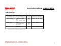
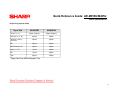
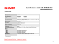
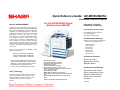
Quick Reference Guide: AR-M355U/M455U Description: Features & Options The AR-M355U/M455U Digital Multifunctional IMAGER Why the AR-M355U/M455U … Targeted for busy mid-volume environments, the AR-M335U/M445U Digital Multifunctional IMAGERs offer powerful Multitasking, Advanced Application Integration and Leading Edge Security. The base model is comprised of a newly engineered 300 MHz Multi-tasking Controller and offer the same technology used in the AR-M550U/M620U/M700U. The advanced features include Dual Head Scanning (Scan2 Technology), Page Stamping, Job Build, Card Shot Copy and Cover Pages. Combine all of this with on-line paper capacity of up to 3100 sheets and enhanced paper handling capability that includes a wide variety of media types up to 97 lb. Index stock. Performance, Flexibility, Productivity, and Security Powerful Network Connectivity* 300 MHz PCL6 Printing System 40 GB Hard Drive Network Tandem Printing Flexible Network Scanning* Ability to end to 6 different destinations allows for a truly digital workflow ¾Send to Desktop ¾Sent to E-mail ¾Send to FTP ¾Send to Print ¾Send to URL ¾Send to FAX ¾Send to I-FAX Each of the host machines is available in three different configurations: Package A, AR-M355UA / AR-M455UA Package B, AR-M355UB / AR-M455UB Package C, AR-M355UC / AR-M455UC Professional Finishing* Features Base U Model IMAGERs include a 35/45 PPM engine, 300 MHz multitasking controller with128 MB memory, and are easily upgraded to support PCL6 Network Printing System, network scanning, Document Filing and Super G3 Fax. Scan2 Technology The new technology enables users to scan both sides of a 2-sided document in one pass, autoduplex documents on paper stocks up to 97 lbs Index, and offer an array of convenience features. 9 9 9 9 9 9 9 9 9 9 9 1 35/45 ppm print speed True multi-tasking engine controller 50-sheet Duplex Single Pass Feeder Document filing system Permanent Font and Form storage Auto Duplexing on stocks up to 97 lb. index New Card Shot feature (copies both sides of an ID card onto a single sheet of paper) Carbon Copy Print mode1 IP/MAC Address Filtering (secure NIC card)1 LDAP support with optional Network Scanner Expansion Kit1 Standard IEEE 1284 and USB 2.0 ports, RJ-45, 10/100 BaseT1 Two-Tray Finisher Saddle-Stitch Finisher Mail Bin Stacker Scalable Security Offerings* Confidential Print Feature User Authentication (E-mail) IP/MAC Address Filtering Data Security Kit (128 bit encryption) Requires PCL6 Network Printing Expansion Kit * Optional 1 Quick Reference Guide: AR-M355U/M455U Pre-Setup: Tools, Documentation, & Admonitions Special Tools & Service Documentation Material Safety Data Sheets (MSDSs)* Description Part Number Product Code AR-M355U/AR-M455U, Service Manual & Circuit Diagram, and Parts Guide Toolbox Basics Mechanical *AR-DU3/DU4, Duplex Unit and Parts Guide • Screwdriver, Phillips #2 • Screwdriver, Flat #1 • Wrench, 1.5mm Hex head *AR-TE4, Upper Exit Tray (Right Side) *AR-TE5, Exit Tray/Cabinet SM-ARC355U/ARM455U Code: 00ZARM455UA1E PG-ARM355U Code: 00ZARM351UP1/ SM-ARDU3/DU4/TE3 Code: 00ZARDU3//A1E PG-ARDU3,DU4 Code: 00ZARDU4/P2 N/A • Feeler gauges *AR-D28, D27, MU2, Paper Feed Unit (Optional Power Supply Unit) SM-ARD28_A1E Code: 00ZARD28//A1E Electrical *AR-FN6, Finisher SM-ARFN6 Code: 00ZARFN6//P1/ *AR-FN7, Saddle Stitch Finisher, *AR-PN1, Punch and Parts Guide SM-ARFN7, ARPN1 Code: 00ZARFN7//A1E PG-AARFN7, ARPN1 Code: 00ZARFN7//P2/ *AR-MS1, Mail-bin Stacker And Parts Guide SM-ARMS1 Code: 00ZARMS1//A1E PG-ARMS1 Code: 00ZARMS1//P2/ • Voltmeter • ESD wrist or ankle strap • Approved surge suppressor • 30x lighted viewing device Miscellaneous • Clean, soft, lint-free cloths • Alcohol Description MSDS No. AR-455MT Toner cartridge (Black) F-01331 AR-455MD Developer (Black) F-31331 AR-455DR Drum * Download MSDSs at http://www.sharp-service.com Electrical/Electronic Component Admonitions WARNING: Electrical hazard. Employ proper precautions when working with high-voltage electrical equipment. ! Laser Admonition For your protection, do not remove protective covers or bypass safety interlocks. n/a E S D CAUTION: Improper handling of electronic components can damage the equipment. Properly ground and wear an electro-static device (ESD) on your wrist or ankle when working with electronic modules. Similarly, use anti-static bags to protect electronic components during storage or shipping. 2 Quick Reference Guide: AR-M355U/M455U Basic System Configuration System configuration Basic system AR-M355U/AR-M455U Host Machine (Package A, B, or C) Necessary options: Any one of the stand/MPD & 2000 sheet paper drawer (AR-D28), the stand/3x 500 sheet paper drawer (ARD27), or the multi-purpose drawer (AR-MU)*. Any one of the upper exit tray extensions ( AR-TE3,AR-TE4, or ARTE5); the finisher (AR-FN6); the mailbin stacker (AR-MS1). AR-EF3 AR-RK2 3 Quick Reference Guide: AR-M355U/M455U Available Configurations Configurations Package B Package A Base Machine + AR-EF3 Scanner + + AR-RK2 Scanner Rack 2500-Sheet Paper Desk Package C Base Machine + AR-EF3 Scanner + + AR-RK2 Scanner Rack 1500-Sheet Paper Desk Base Machine + AR-EF3 Scanner + + + AR-RK2 Scanner Rack 500 Sheet Multi-Purpose Drawer AR-45ABD Cabinet 4 Quick Reference Guide: AR-M355U/M455U Adjustment and Simulation Adjustment Checklist Simulation Entering the Simulation Mode 1. 2. 3. 4. 5. Copy mode key ON → Program key ON → Asterisk (*) key ON → CLEAR key ON →Asterisk key ON → Ready for input of a main code of simulation Entering a main code with the 10-key → START key ON Entering a sub-code with the 10-key → START key ON Select an item with the scroll key and the item key. The machine enters the mode corresponding to the selected item. a) b) 6. Press START key or EXECUTE key to start the simulation operation. To cancel the current simulation mode or to change the main code or the sub code, press the user setup key. *Canceling the simulation mode to return to the normal mode: Press CA key. Simulation List Please refer to the Simulation List (pages 1 through 11) that follows. Note: For detailed instructions, refer to Section 8 of the AR-M355N/M455N Service Manual. 5 Quick Reference Guide: AR-M355U/M455U Simulation List (Pg. 1 of 11) Simulation List (Main/Sub) Function (Purpose) Code Main Sub 1 1 Used to check the operations of the scanner (read) unit and its control circuit. 2 Used to check the operation of sensor and detector in the scanning (read) section and the related circuit. 2 3 4 5 6 7 1 Used to check the operations of the automatic document feeder unit and the control circuit. 2 Used to check the operations of the sensors and detectors in the automatic document feeder unit and the related circuits. 3 Used to check the operations of the loads in the automatic document feeder unit and the control circuits. 2 Used to check the operation of sensor and detector in the finisher and the related circuit. 3 Used to check the operation of the load in the finisher and the control circuit. 6 Used to adjust the stacking capacity of the finisher. (Used to adjust the alignment plate [jogger] stop position in the finisher paper width direction. The adjustment is made by changing the alignment plate home position in the paper width direction by software.) 10 Console finisher (AR-FN7) adjustment. 20 Used to check the mail bin stacker sensor. 21 Used to check the operations of the mail bin stacker loads. 2 Used to check the operations of the sensors and detectors in the paper feed section (desk paper feed/large capacity tray) and the related circuit. 3 Used to check the operations of the loads in the paper feed section (desk paper feed/large capacity tray) and the related circuit. 1 Used to check the operation of the display, LCD in the operation panel and control circuit. 2 Used to check the operation of the heater lamp and the control circuit. 1 Used to check the operation of the paper transport system loads and the control circuit. 2 Used to check the operations of each fan motor and its control circuit. 1 Used to set the operating conditions of aging. 6 Used to set the intermittent aging cycle. 8 Used to set the warm-up time display YES/NO. 6 Quick Reference Guide: AR-M355U/M455U Simulation List (Pg. 2 of 11) Simulation List (Main/Sub) 8 9 1 Used to check and adjust the operations of the developing voltage of each color and the control circuit. 2 Used to check and adjust the operation of the main charger grid voltage in each printer mode and the control circuit. 6 Used to check and adjust the operation of the transfer voltage and the control circuit. 17 Used to check and adjust the operation of the transfer voltage and the related circuit. (Transfer belt cleaning mode.) 1 Used to check and adjust the operation of the load (clutch/solenoid) in the duplex section and the control circuit. 2 Used to check the operations of the sensors and detectors in the duplex section and its control circuit. 10 1 Used to check the operations of the toner motor and the related circuit. 13 0 Used to cancel the self-diag “U!” trouble. (Only when FAX is installed.) 14 0 Used to cancel excluding the self-diag U1/LCC/U2/PF troubles. 15 0 Used to cancel the self-diag “U6-01, 02, 03, F3-12, 22” (large capacity paper feed tray, paper feed trays 1, 2) troubles. 16 0 Used to cancel the self-diag U2 troubles. 17 0 Used to cancel the PF troubles (when the copy inhibit command from the host computer is received). 21 1 Used to set the maintenance cycle. 22 1 Used to check the print count value in each section an each operation mode. (Used to check the maintenance timing.) 2 Used to check the total numbers of misfeed and troubles. (When the number of misfeed is considerably great, it is judged as necessary for repair. The misfeed rate is obtained by dividing this count value with the total counter value.) 3 Used to check misfeed positions and the misfeed count of each position. (if the misfeed count is considerably great, it may be judged as necessary to repair.) 4 Used to check the trouble (self-diag) history. 5 Used to check the ROM version of each unit (section). 6 Used to output the list of the setting and adjustment data (simulations, FAX soft switch, counters). 7 Used to display the key operator code. (This simulation is used when the customer forgets the key operator code.) 8 Used to check the number of use of the finisher, the SPF, and the scan (reading) unit. 9 Used to check the number of use (print quantity) of each paper feed section. 10 Used to check the system configuration (options, internal hardware). 7 Quick Reference Guide: AR-M355U/M455U Simulation List (Pg. 3 of 11) Simulation List (Main/Sub) (cont’d) 22 23 24 25 11 Used to check the use frequency (send/receive) of FAX. (Only when FAX is installed.) 12 Used to check the SPF misfeed positions and the number of misfeed at each position. (When the number of misfeed is considerably great, it can be used as necessary for repair.) 13 Used to check the operating time of the process section (OPC drum, DV unit, toner bottle). 19 Used to check the values of the counters related to the scan mode and the internet FAX mode. 2 Used to check the trouble history of paper jam and misfeed. (If the number of misfeed and troubles is considerably great, it may be judged as necessary to repair.) 80 Used o check the operations of the sensors and detectors in the paper feed and transport sections. 1` Used to clear the misfeed counter, the misfeed history, the trouble counter and the trouble history. The counters are cleared after completion of maintenance.) 2 Used to clear the number of use (the number of prints) of each paper feed section. 3 Used to clear the number of use of the finisher, SPF, and the scan (reading) unit. 4 Used to reset the maintenance counter. 5 Used to reset the developer counter. (The developer counter of the DV unit which is installed is reset.) 6 Used to reset the copy counter. 7 Used to clear the OPC drum counter. (Perform this simulation when the OPC drum is replaced.) 9 Used clear the printer mode print counter and the self print mode print counter. 10 Used to clear the FAX counter. (Only when FAX is installed.) 11 Used to reset the OPC drum rotation time, and the DV unit rotation time counter. ; The developer counter in the DV unit installed Is reset. 15 Used to clear the counters related to the scan mode and the internet FAX mode. 1 Used to check the operations of the developing section (toner concentration, humidity and toner concentration sensor, humidity sensor, temperature sensor output can be monitored.) 2 Used to make the initial setting of toner concentration when replacing developer. 8 Quick Reference Guide: AR-M355U/M455U Simulation List (Pg. 4 of 11) Simulation List (Main/Sub) (cont’d) 26 27 30 3 Used to set the specifications of the auditor. Setting must be made according to the auditor use conditions. 5 Used to set the count mode of the total counter and the maintenance counter. 6 Used to set the specifications (paper, document detection, etc.) of the destination. 10 Used to set the network scanner trial mode. 18 Used to set YES/NO of toner save operation. (This function is valid only in Japan and UK versions.) [Depends on the destination setting of SIM26-6.] For the other destinations, the same setting can be made by the user program P22.) 30 Used to set the operation mode conforming to the CE mark (Europe safety standards). (Conforming to soft start when driving the fusing heater lamp.) 35 Used to set whether the same continuous troubles are displayed as one trouble or the series of troubles with SIM 22-4 when the same troubles occur continuously. 38 Used to set CONTINUE/STOP of printing when maintenance timing is over and the count value reaches 110% of replacement timing (life). 41 Used to set the automatic magnification ratio selection (AMS) in the pamphlet mode. 50 Black-White reverse YES/NO setting. 52 Used to set whether non-print paper (insertion paper, cover paper) (blank image print paper) is counted up or not. 68 Used to set ENABLE/DISABLE of the CA key cancel function of print stop. 1 Used to set the specifications for operations in case of communication trouble between the host computer and MODEM (machine side). (When communication trouble occurs between the host computer MODEM and the machine, the self diag display (U7-00) is printed and setting for inhibition of print or not is made.) 5 Used to enter the machine tag No. (This function allows to check the tag No. of the machine with the host computer.) 1 Used to check the operation of sensors and detectors in other than the paper feed section and the operations of the related circuits. 2 Used to check the operation of sensors and detectors in the paper feed section and the related circuits. 9 Quick Reference Guide: AR-M355U/M455U Simulation List (Pg. 5 of 11) Simulation List (Main/Sub) (cont’d) 40 11 Used to check the multi-purpose tray width detection adjustment value. 12 Used to check the multi-purpose tray width detection adjustment value. 1 Used to check the operation of the document size sensor and the related circuit. (The operation of the document size sensor can be monitored with the LCD display.) 2 Used to adjust the document size sensor sensing level. 3 Used to check the operation of the document size sensor and the related circuit. (The document size sensor output level can be monitored with the LCD display.) 43 1 Used to set the fusing temperature in each operation mode. 44 1 Used to set enable/disable of correction operations in the image forming (process) section. 9 Used to check the data related to the image forming section correction (process correction) result (corrected main charger grid voltage, the developing bias voltage, and the laser power voltage in each print mode). (This simulation allows to check that correction is performed normally or not.) 14 Used to check the output level of the temperature sensor and the humidity sensor. 16 Used to check the toner concentration control data. 2 Used to adjust the copy density in all the copy modes (Auto, Text, Text/Photo, and Photo mode. 9 Used to adjust the print density for each density level (display value) in the copy mode (binary-Text mode). An optional print density can be set for each density level (display value). 10 Used to adjust the print density for each density level (display value) in the copy mode (binary-Photo m ode). An optional print density can be set for each density level (display value). 41 46 10 Quick Reference Guide: AR-M355U/M455U Simulation List (Pg. 6 of 11) Simulation List (Main/Sub) (cont’d) 46 11 Used to adjust the print density for each density level (display value) in the copy mode (binary-Photo mode0. An optional print density can be set for each density level (display value). 12 Used to adjust the print density in the FAX mode (all models). 13 Used to adjust the print density in the FAX mode (each normal mode). (Only when FAX is installed.) 14 Used to adjust the print density in the FAX mode (each fin mode). (Only when FAX is installed.) 15 Used to adjust the print density in the FAX mode (each super fine mode). (Only when FAX is installed.) 16 Used to adjust the print density in the FAX mode (each ultra fine mode). (Only when FAX is installed.) 17 Used to set the gain in shading correction. 18 Used to adjust the gamma (density gradient) in the copy mode. 19 Used to set the auto mode operation specifications in ach mode (copy, scan, FAX). 20 Used to adjust the copy density correction into eh SPF copy mode for the document table copy mode. The adjustment is made so that the copy density becomes the same as that of the document table copy mode. 21 Used to adjust the scanner exposure level in all the scanner modes. 22 Used to adjust the scanner exposure level in the normal text mode. 23 Used to adjust the scanner exposure level in the fine text mode. 24 Used to adjust the scanner exposure level (in the super fine text mode). 25 Used to adjust the scanner exposure level in the ultra fine text mode. 27 Used to adjust the gamma (density gradient) of the network scanner mode. 31 Used to adjust sharpness of the copy mode. 11 Quick Reference Guide: AR-M355U/M455U Simulation List (Pg. 7 of 11) Simulation List (Main/Sub) (cont’d) 46 39 Used to adjust sharpness of the FAX mode. 45 Used to adjust the image density in the FAX mode (600dpi). 46 Used to adjust sharpness of the scanner mode. 1 Used to adjust the copy magnification ratio (in the main scanning and the sub scanning directions). 5 Used to adjust the copy magnification ratio in the sub scanning direction. 6 HSYNC cycle adjustment. 1 Used to adjust the copy image position and the void area (image loss) adjustment on print paper in the copy mode. (The similar adjustment can be performed with SIM 50-5 and 50-2 (Simplified method].) (Document table mode.) 2 Used to adjust the document scan position, the image print position, and the void area (image loss). (Simple adjustment) (This adjustment is the simple method of SIM 50-1.) (Document table mode.) 5 Used to adjust the print image position and the void area (image loss) on print paper. (Adjustment as the print engine.) (This adjustment is reflected on all the FAX/printer/copy modes.) 6 Used to adjust the copy image position and void area (image loss) on print paper in the copy mode. (The similar adjustment can e performed with SIM 50-7 [simple method].) (SPF mode). 7 Used to adjust the copy image position and void area (image loss) on print prepare in the copy mode. (The similar adjustment can be performed with SIM 50-6). (SPF mode.) 10 Used to adjust the print image off-center position. (Adjusted separately for each paper feed section.) 12 Used to adjust the scan image off-center position. (Adjusted separately for each scan mode.) 27 Used to adjust the image loss of the scan image in the FAX/scan mode. 51 2 Used to adjust the contact pressure of paper on the resist roller of each section (each paper feed, duplex feed and SPF paper feed of the copier). (This adjustment is required when the print image position variations are considerably great or when paper jams occur too frequently.) 53 6 Used to adjust the DSPF width detection level. 7 Used to enter the SPF width detection adjustment value. 8 Used to adjust the document scan start position. (Used to adjust the scanner scan position into eh SPF mode front scan.) 48 50 12 Quick Reference Guide: AR-M355U/M455U Simulation List (Pg. 8 of 11) Simulation List (Main/Sub) (cont’d) 55 1 Used to set the specifications of the engine control operations. (PCU-PWB). 2 Used to set the specifications of the scanner control operations. (Scanner control PWB). 3 Used to set the specifications of the controller operations. (MFP control PWB). 56 1 Used to transfer the MFP controller data. (Used to repair the PWB.) 60 1 Used to check the MFP control (DRAM) operations (read/write). 61 1 Used to check the operation of the scanner (write) unit (LSU). 2 Used to adjust the laser power (absolute value) in the copy mode. 3 Used to adjust the laser power (absolute value) in the FAX mode. 4 Used to adjust the laser power (absolute value) in the printer mode. 1 Used to format the hard disk. 2 Used to check the operation of the hard disk (read/write). (Only in the model with a disk installed). (Partial check.) 3 Used to check the operations of the hard disk (read/write). (All areas check.) 6 Used to check the operations of the hard disk. (The self-diag operation of the SMART function I executed. 7 Used to check the operation soft the hard disk. (/The result of the self-diag operation of the SMART function is printed out.) 8 Used to format the hard disk (the system area excluded). 10 Used to delete a job complete list (also to delete job log data). 11 Used to delete document filing data. (The management area (standard folder, user folder) is cleared.) 1 Used to check the result of shading correction. (The shading correction data are displayed.) 2 Used to execute shading. 7 Used to adjust the white plate scan start position for shading. (Document table mode.) 1 Used to check the operation of the printer section (self-print operation). (The print pattern, the paper feed mode, the print mode, the print quantity, and the density can be optionally set). 62 63 64 13 Quick Reference Guide: AR-M355U/M455NU Simulation List (Pg. 9 of 11) Simulation List (Main/Sub) (cont’d) 65 66 1 Used to adjust the touch panel (LCS display section) detection position. 2 Used to check the result of the touch panel (LCD display) detection position adjustment. (The coordinates are displayed.) 1 Used to change and check the FAX soft switch functions. (Used to change and check the functions provided for the FAX soft switches.) (Only when FAX is installed.) 2 Used to clear the FAX soft switch function data and to set to the default. (Excluding the adjustment values.) (Only when FAX is installed.) 3 Used to check the operation of the FAX PWB memory (read/write). (This adjustment is required when the PWB is replaced with a new one.) (Only when FAX is installed.) 4 Used to check the output operation of data signals in each data output mode of FAX. (Used to check the operation of MODEM.) Send level: Max. (Only when FAX is installed.) 5 Used to check the output operation of data signals in ach data output mode of FAX. (Used to check the operation of MODEM.) An output is sent at the send level set by the soft switch. (Only when FAX is installed.) 6 Used to print the confidential pass code. (Used when the confidential pass code is forgotten.) (Only when FAX is installed.) 7 Used to print the mage memory data (memory send/receive). (Only when FAX is installed.) 8 Used to check the output operation of various sound signals of FAX. (Used to check the operation of the sound output IC.) Send level: Max. (Only when FAX is installed.) 9 Used to check the output operation of various sound signals of FAX. (Used to check the operation of the sound output IC.) An output is sent at the send level set by the soft switch. (Only when FAX is installed.) 10 Used to clear all data of the image memory (memory send/receive). The confidential data are also cleared at the same time. (Only when FAX is installed.) 11 Used to check the output operation of FAX G3 mode 300bps. (Used to check the operation of MODEM.) Send level: Max. (Only when FAX is installed.) 12 Used to check the output operation of FAX G3 mode 300bps. (Used to check the operation of MODEM.) An output is send at the send level set by the soft switch. (Only when FAX is installed.) 13 Used to enter (set) the number of FAX dial signal output test. (The dial number set by this simulation is outputted when the dial signal output test is made by SIM 66-14-16.) (Only when FAX is installed.) 14 Used to set the make time in the FAX pulse dial mode (10pps) and to test the dial signal output. (The dial number signals et by SIM 66-13 is outputted.) Used to check troubles in dialing and to check the operation. (Only when FAX is installed. 14 Quick Reference Guide: AR-M355U/M455U Simulation List (Pg. 10 of 11) Simulation List (Main/Sub) (cont’d) 66 15 Used to set the make time in the FAX pulse dial mode (20pps) and to test the dial signal output. (The dial number signal set by SIM 6613 is outputted.) The send level can be set to an optional level. Used to check troubles in dialing and to check the operation. (Only when FAX is installed.) 16 Used to check the dial signal (DTMF) output in the FAX tone dial mode. (The dial number signal set by SIM 66-13 is outputted. The send level can be set to an optional level. Used to check troubles in dialing and to check the operation. (Only when FAX is installed.) 17 Used to check the dial signal (DTMF) output in the FAX tone dial mode. Send level: Max. Used to check the operation. (Only when FAX is installed.) 18 Used to check the dial signal (DTMF) output in the FAX tone dial mode. An output is sent at the send level set by the soft switch. Used to check the operation. (Only when FAX is installed.) 19 Used to back-up the HDD data into the Flash memory (optional FAX expansion memory: AR-MM9). (Only when FAX is installed.) 20 Used to read the back-up data by SIM 66-19 to the SRAM/HDD. (Only when FAX is installed.) 21 Used to print information related to FAX (various registrations, communication management, file management, system error protocol). (Only when FAX is installed.) 22 Used to adjust the handset volume. (Only when the FAX is installed.) 23 Used to download the FAX program. (Only when FAX is installed.) Not used in the market. (For development.) 24 Used to clear the FAST memory data. (Only when FAX is installed.) 25 Used to register the FAX number for Model dial-in. (Only when FAX is installed.) Not used in the market. (For development.) 15 Quick Reference Guide: AR-M355U/M455U Simulation List (Pg. 11 of 11) Simulation List (Main/Sub) (cont’d) 66 26 Used to register external telephone numbers for Modem dial-in. (Only when FAX is installed.) Not used in the market. (For development.) 27 Used to register the transfer number for voice warp. (Only when FAX is installed.) Not used in the market. (For development.) 29 Used to clear data related to an address book (one-touch registration, program registration/expansion, relay memory box registration, each table content.) 30 Used to check the change in the TEL/LIU status. (Only7 when FAX is installed.) 31 Used to check the relay operation. (Only when FAX is installed.) 32 Used to check the receive data (fixed data) from the line. (Only when FAX is installed.) 33 Used to check the signal (BUSY TONE / CNG / CED / FNET / DTMF) detection. (Only when FAX is installed.) 34 Used to measure the communication time of test image data. (Only when FAX is installed.) 35 Modem program rewriting. (Only when FAX is installed.) Not used in the market. (For development.) 36 Used to check interface between MFPC controller and MDMC. (Check of the data line or the command line.) (Only when FAX is installed.) 66 67 39 Used to set the destination specifications. (Only when FAX is installed.) 42 PIC program rewriting. (Only when FAX is installed.) 43 PIC adjustment value writing. (Only when FAX is installed.) 2 Used to check the operation of the parallel I/F o the printer. (This simulation is for production only, and requires a special tool for execution.) (Not used in the market.) 11 Used to set YES/NO of the parallel I/F select signal of the printer. 16 Used to check the operation of the network card. 16 Quick Reference Guide: AR-M355U/M455U Supplies Supply System Table Description Content Toner cartridge (Black) Toner cartridge (with IC) (x 10) (Toner: Net weight 750 g) Developer (Black) Developer (Developer: Net weight 500 g) (x 10) Drum OPC drum (x 1) Note 1: Life Product Code / MSDS No. 350K (35K x 10) AR-455MT / MSDS No. F-01331 1000K (100K x 10) AR-455MD / MSDS No. F-31331 200K AR-455DR (No MSDS required) The other maintenance parts which are not listed above are registered as service parts. 17 Quick Reference Guide: AR-M355U/M455U Supplies (cont’d) Maintenance Parts List Item Content Life Model Name Remarks 200K Maintenance Kit Cleaner blade (x 1) Drum separation pawl (x 4) MC unit *1 (x 1) Toner receiving seat (x 1) Side malt F (x 1) Side malt R (x 1) Transfer roller (x 1) Discharge blade (x 1) Paper dust removing unit (x 1) DV blade (x 1) DV side seal F (x 1) DV side seal R (x 1) Upper heat roller (x 1) Fusing separation pawl (Upper) (x 4) Lower heat roller (x 1) Fusing separation pawl (Lower) (x 2) Cleaning Roller (x 1) Bearing (x 2) 200K AR-455KA1 *1: Screen grid, charging plate, and MC cleaner unit are included. Staple cartridge Staple cartridge (x 3) 3000 times (x 3) AR-SC1 Cartridge for AR-FN4 Common with cartridge for ARFN6 Staple cartridge Staple cartridge (x 3) 5000 times (x 3) AR-SC2 Cartridge for AR-FN7 Note: The other maintenance parts which are not listed above are registered as service parts. 18 Quick Reference Guide: AR-M355U/M455U Basic Specifications Engine Copy Speeds (PPM) Paper Size AR-M355N AR-M455N 35ppm (31ppm*) 45ppm (40ppm*) A4R (8.5” x 11” R) 25ppm 30ppm A5R/5.5” x 8.5”R, Invoice-R 35ppm 45ppm B5 35ppm 45ppm B5R, Executive-R 25ppm 30ppm A3/(11” x 17”) 17ppm 20ppm 8K 17ppm 20ppm 16K 35ppm 45ppm A4 (8.5” x 11”) * Paper feed from Manual Bypass Tray 19 Quick Reference Guide: AR-M355U/M455U Basic Specifications (cont’d) Functional Speeds Warm Up Time: < 80 secs. First Copy Times: Document glass #1 DSPF AR-M355U: < 4.9 sacs. < 6.0 secs. Jam Recovery Times: About 30 sec. (Under standard condition of 60 seconds left after side cover opening, polygon motor halt) Multi-Copy Max: 999 sheets Void Width: Lead Edge: 5mm or less Rear Edge: 5mm or less Image Loss (Normal) 5mm or less External Dimensions: W x D x H: Occupied Space Dimensions: W x D: Weight: Engine: Desk: Rack: DSPF: 826 x 665 x 1127mm (32.5” x 26.2” x 44.4”) including automatic document feeder. 963 x 665mm (37.9” x 26.2”) including automatic document feeder Power Source 100V system (100-127V), 50/60 Hz, Inlet type power cord Power Consumption AR-M355U 1440W; AR-M455U = 1440W AR-M455U: < 4.4 secs. < 5.3 secs. Approximately 38.9kg (85.8 lbs) Approximately 32.9kg (72.6 lbs) Approximately 7.4kg (16 lbs) Approximately 2lkg (46 lbs) *1: During OC mode. 20 Quick Reference Guide: AR-M355U/M455U Cautions for Servicing & Prohibited Printing List Cautions for Servicing Prohibited from Printing by Law □ Do not touch the photoconductive drum. Scratches or smudges on the drum will cause dirty printouts. □ Do not make any modifications to this machine. Doing so may result in personal injury or damage to the machine. □ The fusing unit is extremely hot. Exercise care in this area. □ Since this machine is heavy, it is recommended that it be moved by more than one person to prevent injury. □ When connecting this machine to a computer, be sure to first turn both the computer and the machine off. □ Do not throw toner or a toner cartridge into fire. Toner may be spattered, causing a burn. □ Store toner or toner cartridges in a hard-to-reach place for child safety. □ Do not print anything that is prohibited from printing by law. The following items are normally prohibited from printing by national law. Other items may be prohibited by local law. • Money • Stamps • Bonds • Stocks • Bank drafts • Checks • Passports • Driver’s licenses □ Do not look directly at the light source of the scanner module. Doing so may damage your eyes. □ Five adjusters are provided on all optional stand/paper drawer u nits. These adjusters should be lowered until they contact the floor. 21 Quick Reference Guide: AR-M355U/M455U PWB Repair PWB Repair The PWBs listed below can be forwarded to the following address for repair. Sharp Electronics Corporation Product and Board Repair Department 650 1300 Naperville Drive Romeoville, IL 60446 Repair PWBs Description Part Number Price Rank Scanner Control PWB CPWBX1635DS51 BV MFP Control PWB CPLTM6464FC53 CU PCU PWB CPWBX1637DS56 BX Important: When returning the MFP Control PWB or Scanner Control PWB, be sure to remove the EEPROMs from the PWBs and install them on the new PWBs that you receive. The EEPROM contains machine settings and most importantly the machine serial number. 22 Quick Reference Guide: AR-M355U/M455U Power Consumption & Environmental Data Power Consumption AR-M355U 1440W 1550W 1850W Max. Power Except for Taiwan Consumption Taiwan 220V AR-M455U 1440W 1550W 1850W AR-M355U Maximum Power Consumption Watts Ozone Peak Operating Noise Standby Operation Standby Operation (PPM) Standby Operation 184.75wh 1440wh < 80 W < 184 W < 0.1 (5.0 dB) (6.8 dB) AR-M455U Maximum Power Consumption Watts Ozone Peak Operating Noise Standby Operation Standby Operation (PPM) Standby Operation 223.25wh 1440wh < 95 W < 223 W < 0.1 (5.0 dB) (6.8 dB) 23 Quick Reference Guide: AR-M355U/M455U Flash ROM Flash ROM Version Up (Firmware ROM Upgrade) Procedures General Information The Flash ROM Version Up procedures enable writing of the program data from a PC to the target PWBs which becomes source ROM. Target PWBs and ROMs include: • PCU PWB - PCU Flash ROM • MFP Control PWB - Boot Flash RO - Main Flash ROM • Scanner PWB - Scanner Flash ROM • Fax PWB - Fax Flash ROM Two Procedures are Available to Write to ROM 1. Procedure 1 (Collectively Writing to “Batch”) 2. Procedure 2 (Using the CN6 of the Controller PWB to Write ROMs Individually) After choosing the applicable procedure, make sure you have the necessary items on hand for upgrading as listed under Preparation. Preparation The following items are required to perform an update procedure. • Host machine with operating ROM in it • Windows/Personal computer (operating in MS-DOS mode) with a USB or parallel port • USB cable or Centronics cable (to connect the PC and the Controller PWB) • Software for upgrading (SFU collective file or SFU unit-specific files) • Spare Flash ROMs for PCU, Controller Boot, and Scanner) • Updated Firmware of FCOPY.EXE and/or File2PRN.EXE. (latest version downloaded from Sharpnet©) 24 Quick Reference Guide: AR-M355U/M455U Flash ROM (cont’d) Flash ROM Version Up (Firmware ROM Upgrade) Procedures (cont’d) DIP Switches Note: When updating the ROM, the DIP switches on the back of the machine must be set properly. Follow the Setting the DIP Switches procedure below. Setting the DIP Switches 1. Remove the screw marked with an asterisk (*) from the Controller PWB at the back of the machine and rotate the plate part to access the DIP switches. See illustration. Note: There are two DIP switches on the Controller: the Diag Mode Switch (on the left) and the Write Protect Switch (on the right). The switches are set to the Protect mode (switches are in the Up position) during normal operation. Protect mode is the default. In order to write to the ROM, the switches must be changed to the down position (Diag Mode). This releases the write protection. 2. Upon completion of the upgrade procedure, remember to return the switches to the Up position (Write Protect), and then rotate the plate back over the DIP switches to the original position, and tighten down the screw. 25 Quick Reference Guide: AR-M355U/M455U Flash ROM (cont’d) Flash ROM Version Up (Firmware ROM Upgrade) Procedures (cont’d) Upgrade Procedure 1: Collectively Writing with Each ROM Inserted into the Specified Slot Note: Make certain all of the ROMs on the PCU, FAX, and scanner are operating ROMs. An empty ROM (a ROM that cannot boot the machine) cannot be used for writing. Setup 1. 2. 3. 4. 5. 6. Set the Diag Mode Switch DIP switch (located on the left side on the back of the machine) to the diag mode. (See Setting the DIP Switches.) Make certain the scanner unit is connected to the machine. When a FAX is installed, make certain the FAX unit is connected to the machine. Connect the PC and Controller PWB with the Centronics cable or USB cable. START key → OK key Power ON the PC. Power ON the machine to be updated. Print (Document filing) key → Up/Down select key FAX/Image send key → Up/Down select key When the machine is booted by the diag mode, each operation is performed with the hard keys of the scanner. The window display is made by the LCD panel. The keys used in the diag mode are assigned as shown in the box to the right. Job status key → Menu key Clear key → BACK key When the machine is booted, the following display is shown. 3. Press the START key, and the following window is displayed. Update Procedures 1. 2. Press the Job status key a few times to display the following windows. Note 1: The LED flashes and the display is changed sequentially (as shown below) when files are transferred from the PC by Fcopy.EXE or File2PRN.EXE. Note: If using File2PRN.EXE, select the connection type (USB or parallel) with the Up/Down select key. 26 Quick Reference Guide: AR-M355U/M455U Flash ROM (cont’d) Flash ROM Version Up (Firmware ROM Upgrade) Procedures (cont’d) Upgrade Procedure 1: Collectively Writing to “Batch” (cont’d) Note 2: The backlight of the LCD is instantaneously turned OFF when the scanner is updated. Do not power OFF since it is not a breakdown. Wait several minutes until “Result: OK” displays, then press the Up/Down key to make certain there is no “Result: NG” for each ROM. Note 3: On machines that do not have a FAX installed, when the collective files are updated, the display is “Result: NG”. “Result: NG” is displayed in this instance for FAX. In all other “Result: NG” displays, see the section titled Troubleshooting “Result:NG”. 4. Reboot the machine. Use the Up/Down key on window 1) to verify that the version of the updated software has been updated correctly. 5. Power OFF and reset the DIP switches to the Up position (Write Protect default). End of Procedure 1. 27 Quick Reference Guide: AR-M355U/M455U Flash ROM (cont’d) Flash ROM Version Up (Firmware ROM Upgrade) Procedures (cont’d) Upgrade Procedure 2: Using the CN6 of the Controller PWB to Write ROMs Individually Note: By using an empty slot of the Controller PWB, writing can be made to an empty ROM that is not operating. Setup 1. 2. 3. 4. 5. 6. 7. Set the Diag Mode Switch DIP switch (located on the left side on the back of the machine) to the diag mode. (See Setting the DIP Switches.) Insert the applicable ROM of the PCU, the SCN or the FAX into the empty slot (CN6) on the Controller PWB. Make certain the scanner unit is connected to the machine. When a FAX is installed, make certain the FAX unit is connected to the machine. Connect the PC and Controller PWB with the Centronics cable or USB cable. Power ON the PC. Power ON the machine to be updated. 9. Press the MENU key a few times to display the following window. Note: When using File2PRN.EXE, press the Up/Down key to select the appropriate connection type (either USB or parallel). 10. Press OK key, and the following window is displayed. Update Procedures 8. When the machine is booted, the following display is shown. Note: The LED flashes and the display is changed sequentially (as shown below) when files are transferred from the PC by Fcopy.EXE or File2PRN.EXE. 28 Quick Reference Guide: AR-M355U/M455U Flash ROM (cont’d) Flash ROM Version Up (Firmware ROM Upgrade) Procedures (cont’d) Upgrade Procedure 2: Using the CN6 of the Controller PWB to Write ROMs Individually 11. Press OK key, and the following window is displayed. 12. Use the Up/Down key to select the slot No. where the ROM is inserted and press the OK key. Note: The LED flashes and the display is changed sequentially (as shown below). Wait several minutes until “Result: OK” displays. A13. After turning OFF the power, replace the newly written ROM with the ROM of the specified slot of the PWB. 14. Power ON and reboot the machine. Use the Up/Down key on window 1) to verify that the version of the updated software has been updated correctly. 15. Power OFF and reset the DIP switches to the Up position (Write Protect default). End of Procedure 2. 29 Quick Reference Guide: AR-M355U/M455U Operation Panel and Troubleshooting “Result:NG” Operation Panel When the machine is booted by the diag mode, each operation is performed with the hard keys of the scanner. The window display is made by the LCD panel. The keys used in the diag mode are assigned as follows: START key Document filing key FAX/Image send key Job status key Clear key → → → → → OK key Up/Down select key Up/Down select key Menu key BACK key Troubleshooting “Result:NG” (cont’d) Event: In rare cases, the ROM is broken down. Action: Check the ROM, and retry writing. If the trouble remains, replace the ROM. Turning Off the Power During Update When the power is turned OFF during the update process, though the machine is booted, data writing cannot be assured. Retry update as follows: 1. When the power is turned OFF during the update process of Upgrade Procedure 1: Troubleshooting “Result:NG” If a “Result:NG” is displayed, check for the following possible causes. Event: The Write Protect DIP switch setting is incorrect. Action: Make sure that the Write Protect switch of the Controller PWB is set to the release side (down). Retry the update procedure. If the machine is not booted or the hard keys are not invalid (**), retry of the update is failed again, replace the ROMs with the spare one of the PCU, the controller BOOT, and the scanner ROM, and try the update procedure of Upgrade Procedure 2 for the replaced ROMs. (** When the backlight of the display is lighted but the hard keys are invalid, all LED’s flash.) 2. When the power is turned off during the update process of Upgrade Procedure No. 2. Note: Data cannot be written to the ROM if the Write Protect switch is not set to Release (down). Set the DIP switch properly and retry updating. Event: The FAX cable is not connected. (The FAX is NG.) Writing cannot occur. Action: Connect the cable properly and retry writing. 30 Quick Reference Guide: AR-M355U/M455U Operation Panel and Troubleshooting “Result:NG” Update Window Display in Normal Booting After completion of updating, when the power is turned OFF and the DIP switches on the back of the machine are set to the normal side and the machine is booted, the update window is displayed as shown below instead of the normal boot window, the PCU or the scanner may not have been properly updated. Update Process Flow The brief descriptions on the update procedures are as follows: For turning off during update, refer to “Turning Off the Power During Update”. If the update window is displayed after booting with the DIP switches on the back of the machine set to the normal side, refer to “Update Window Display in Normal Booting”. At that time, use the Up/Down key to check the version of the PCU or the scanner. If the version is displayed as “BootMode,” or if the key operation is invalid (all the LEDs are flashing), retry updating as follows: 1. When the key operation is possible and the version is displayed as “BootMode”: Turn OFF the power and retry the update procedure of Procedure 2. At that time, be sure to set the dip switches properly. After updating again, if the result is still NG, replace the ROMs with the spar one of the PCU and the scanner ROM, and perform the update procedure for the replaced ROMs. 2. When the key operation is invalid: Turn OFF the power and replace the ROMs with the spare one of the PCU and the scanner ROM, and perform the update procedure for the replaced ROMs. Be sure to set the DIP switches properly. 31 Quick Reference Guide: AR-M355U/M455U File Transfer File Transfer Process Flow Chart File Transfer Procedures File Transfer by Fcopy.EXE 1. 2. For file transfer by Fcopy, put Fcopy.exe and the files in the same directory, and boot the MS-DOS. Go to the directory of the files, and type “Fcopy file name and the transfer occurs. Note: In the following example, the SFU file is in the C:\ROM directory and it is transferred. File Transfer by File2PRN.EXE 1. Set the machine to which the files are to be transferred as a printer. (The connection types as a printer are parallel port, network, and USB.) Note: An IP address setting is required for transfer by the network connection. 2. Execute File2PRN.EXE to transfer the files. The follow window displays. 32 Quick Reference Guide: AR-M355U/M455U File Transfer File Transfer Procedures (cont’d) File Transfer by USB Connection When the update is made by File2PRN and USB connection, USB is used as a printer port similar to the other connections (parallel, network). Setup 1. 2. 3. 4. 5. Set the machine as a printer which is connected to the PC in a connection type other than USB. Boot the machine in the diag mode conforming to the normal ROM update procedures. Connect the PC and the machine with the USB cable. The PC system detects a new hardware by Plug & Play function. The driver of SHARP AR-M455N is automatically installed. Note: The model name is displayed as SHARP AR-M455N regardless of the actual model name. 6. 7. Follow the normal ROM update procedures to bring the machine into the data reception status. Execute File2PRN, specify the printer and execute the file transfer. (Example: SHARP AR-M455N SPDL2 on USB001). 33