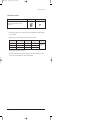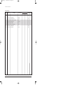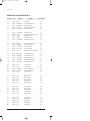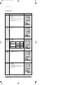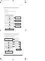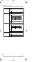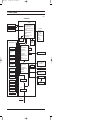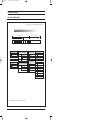
1
SPLIT-TYPE AIR CONDITIONER
Basic : AS12HPCN
Model : AS12HM3
Model :
Model Code :
Model Code :
Model Code :
SERVICE
Manual
AIR CONDITIONER
THE FEATURE OF PRODUCT
■
Energy Saving Function
■
High Impressive & Elegant Design
■
Excellent Dust Collection Filter
: The metallic dust filter is used.
AS09HPCN/AS12HPCN/AS09HPDN/AS12HPDN
■
Multi Functional Cleaning System
: The anti allergy filter and activated deodorizing
filter are adopted.
■
Human Touch Remote control
AS09HPCX/AS12HPCX/AS09HPDX/AS12HPDX
For more information, Please access to our service web site (http://itself.sec.samsung.co.kr)
24610A(1)_1
11/10/05 6:25 PM
Page 1
Contents
11. Precautions ........................................................................................................................................... 1-1
1-1 Installing the air conditioner .......................................................................................................... 1-1
...............................................................................................
1-1
................................................................................................................................
1-1
........................................................................................................................
1-2
....................................................................................................................................................
1-2
1-2 Power supply and circuit breaker
1-3 During operation
1-4 Disposing of the unit
1-5 Others
12. Product Specifications .............................................................................................................. 2-1
..................................................................................................................
2-1
...........................................................................................................................
2-2
....................................................................................................................
2-4
..........................................................................
2-5
.......................................................................................
2-7
2-1 The Feature of Product
2-2 Name of Each Part
2-3 Product Specifications
2-4 The Comparative Specifications of Product
2-5 Accessory and Option Specifications
13. Alignment and Adjustments................................................................................................. 3-1
...................................................................................................
3-1
......................................................................................................
3-5
3-1 Error mode and check method
3-2 Setting Option Setup Method
14. Disassembly and Reassembly........................................................................................... 4-1
4-1 Indoor Unit
...........................................................................................................................................
4-1
........................................................................................................................................
4-5
4-2 Outdoor Unit
15. Exploded Views and Parts List ......................................................................................... 5-1
...........................................................................................................................................
5-1
Unit .........................................................................................................................................
5-7
In ...................................................................................................................................
5-9
5-1 Indoor Unit
5-2 Outdoor
5-3 Ass'y Control
16. Electrical Parts List ....................................................................................................................... 6-1
17. Wiring Diagram .................................................................................................................................. 7-1
18. Schematic Diagram ....................................................................................................................... 8-1
19. Circuit Descriptions ..................................................................................................................... 9-1
9-1 PCB Circuit Descriptions ................................................................................................................. 9-1
9-2 Refrigerating Cycle Diagram ......................................................................................................... 9-2
24610A(1)_1
11/10/05 6:25 PM
Page 2
Contents
10. PCB Diagram .......................................................................................................................................10-1
11. Operating Instruction and Installation ........................................................................11-1
11-1 Main Function .................................................................................................................................... 11-1
11-2 Wireless Remote Control-Buttons and Display ................................................................... 11-4
12. Troubleshooting ...............................................................................................................................12-1
12-1 Items to be checked first .............................................................................................................. 12-1
12-2 Fault Diagnosis by Symptom ...................................................................................................... 12-2
12-3 PCB Inspection Method ................................................................................................................ 12-6
12-4 Main Part Inspection Method ...................................................................................................... 12-8
13. Block Diagram ....................................................................................................................................13-1
14. Reference Sheet ...............................................................................................................................14-1
14-1 Index for Model Name ................................................................................................................... 14-1
14-2 Refrigerant Pressure during the Charging ............................................................................ 14-2
14-3 Pressure & Capacity mark ........................................................................................................... 14-2
14-4 Q & A for Non-trouble..................................................................................................................... 14-3
14-5 Cleaning/Filter Change.................................................................................................................. 14-6
14-6 Installation ........................................................................................................................................... 14-8
14-7 Installation Diagram of Indoor Unit and Outdoor Unit ...................................................... 14-9
24610A(1)_1
11/10/05 6:25 PM
Page 1-1
1. Precautions
1-1 Installing the air conditioner
● Users should not install the air conditioner by themselves.
Ask the dealer or authorized company to install the air conditioner except the window-type air conditioner in U.S.A and Canada.
● If you don’t install the air conditioner properly, it may cause a fire, a water leakage or an electric shock.
● You must install the air conditioner according to the national wiring regulations and safety regulations.
● Install the indoor unit higher than 2.5m from the floor to avoid the injury caused by the operation of the fan.
(except the window-type air conditioner)
● The manufacturer is not responsible for any accidents or injury caused by an incorrect installation.
● When installing the built-in type air conditioner, keep all electric cables such as the power cable and the connection cord in pipes,
ducts, or cable channels to protect them from the danger of impact or any other incidents.
1-2 Power supply and circuit breaker
● If the power cord of the air conditioner is damaged, it must be replaced by the manufacturer or a qualified person in order to
avoid a hazard.
● The air conditioner must be plugged into an independent circuit if applicable or connect the power cable to the auxiliary circuit
breaker.
An all pole disconnection from the power supply must be incorporated in the fixed wiring with a contact opening of >3mm.
● Do not extend an electric cord to the air conditioner.
● The air conditioner must be plugged in after you complete the installation.
1-3 During operation
● Do not repair the air conditioner at your discretion.
It is recommended to contact a service center directly.
● Never spill any kind of liquid on the air conditioner.
If this happens, turn off the air conditioner and contact an authorized service center.
● Do not insert anything between the airflow blades to prevent damage of the inner fan and consequent injury.
Keep children away from the air conditioner.
● Do not place any obstacles in front of the air conditioner.
● Do not spray any kind of liquid into the indoor unit. If this happens, turn off the air conditioner and contact a service center.
● Make sure that the air conditioner is well ventilated at all times:
Do not place a cloth or other materials over it.
● Remove the batteries if you don’t use the remote control for a long time. (If applicable)
● Use the remote control within 7 meters from the indoor unit. (If applicable)
Samsung Electronics
1-1
24610A(1)_1
11/10/05 6:25 PM
Page 1-2
1-4 Disposing of the unit
● Before throwing out the air conditioner, remove the batteries from the remote control.
● When you dispose of the air conditioner, consult your dealer. If pipes are removed incorrectly, refrigerant may blow out and
cause air pollution. When it contacts with your skin, it can cause skin injury.
● The package of the air conditioner should be recycled or disposed of properly for environmental reasons.
1-5 Others
●
●
●
●
1-2
Never store or load the air conditioner upside down or sideways to prevent the damage to the compressor.
Young children or infirm persons should be always supervised when they use the air conditioner.
Max current is measured according to IEC standard for safety.
Current is measured according to ISO standard for energy efficiency.
Samsung Electronics
24610A(1)_1
11/10/05 6:25 PM
Page 2-1
2. Product Specifications
2-1 The Feature of Product
■ Energy saving function
Makes a room cool with and energy saving and arises the efficiency of air conditioner.
■ High impressive & elegant design
With a Smart and fashionable style, the high impressive interior design allow this product to set place in anywhere.
■ Excellent dust collection filter
With a metallic dust filter that upgrades the dust collection function than a common plastic filter, you can enjoy the best
cleanliness.
■ Multi functional cleaning system
With an anti-allergy filter and activated deodorizing filter, it removes an allergy antigen as well as a tobacco odor.
■ Human touch remote control
The use of air conditioner is easier and more convenient by the human touch remote control of new design.
Samsung Electronics
2-1
24610A(1)_1
11/10/05 6:25 PM
Page 2-2
2-2 Name of Each Part
2-2-1 Indoor Unit
The design and shape can be changed according to the model.
Air Inlet
Room Temperature sensor
Power(On/Off) button
Air filter
(under the grille)
Air flow blades
(outlet)
Set temperature &
room temperature
Operation indicator
(Auto-Cool, Cool, Dry, Fan : Blue
Auto-Heat, Heat : Orange)
Auto cleaning indicator
(Blue)
Turbo function indicator
(Blue)
Energy saving indicator
(Blue)
Timer indicator
(Orange)
Anions indicator
(Blue)
Fan speed indicator
(Blue)
Remote control sensor
Note : • In the Auto mode, 2 fan indicators increase and decrease continuously and turn round.
• In the modes except the Auto mode, the fan speed indicator increases and decreases
continuously and turn round each time you press the
button. If you set the Turbo
function, the fan speed indicator turns round with the maximum setting and speed.
• If you want to turn on/off the Display during operation, press the
button on
the remote control.
• The room temperature sensor senses air temperature around the
sensor, and shows the temperature on the display.
2-2
Samsung Electronics
24610A(1)_1
11/10/05 6:25 PM
Page 2-3
Product Specifications
2-2-2 Outdoor Unit
Air Inlet(Rear)
Air Outlet
Connection Valve
Samsung Electronics
2-3
24610A(1)_1
11/10/05 6:25 PM
Page 2-4
2-3 Product Specifications
AP09HPC
AS09HPD
Model
Item
Indoor unit
Type
Outdoor unit
Indoor unit
Outdoor unit
Wall-mounted
Wall-mounted
Cooling
kW
2.70
3.50
Heating
kW
2.90
3.80
Dehumidifying
|/h
1.0
1.4
Cooling
Air Volume
Heating
Performance
Cooling
Noise
Heating
Energy Efficiency Ratio
Cooling
m3/min
(H/M/L)
7.5/6.9/6.3
25
8.3/7.0/5.7
25
8.0/7.4/6.8
25
9.5/8.9/8.3
25
dB
(H/L)
40/30
51
43/31
53
40/30
51
43/31
53
3.21
3.21
3.41
3.22
1-220/240-50
1-220/240-50
840
1,090
850
1,180
3.7
5.0
3.7
5.3
97.3
98.7
97.3
96.8
A
21
28
m
2.1
2.1
5G
5G
250V-10A
250V-10A
W/W
Heating
Power
ph-V-Hz
Power Consumption
Cooling
W
Heating
Operating Current
Cooling
A
Heating
Power
AS12HPC
AS12HPD
Cooling
Power Factor
%
Heating
Starting Current
Length
Power Cord
Number of Core Wire
Capacity
Outer Dimension
WidthxHeight
xDepth
Weight(Net)
Refrigerant Pipe
mm
950x268x165
720x530x260
950x268x165
720x530x260
inch
37.4x10.6x6.5
28.3x20.9x10.2
37.4x10.6x6.5
28.3x20.9x10.2
kg
9.0
31.0
9.5
33.0
Liquid
mmxL(m)
ø6.35x5
ø6.35x5
Gas
mmxL(m)
ø9.52x5
ø12.70x5
DxL(mm)
ø18x550
ø18x550
Rotary, G4A091JU1EP
Rotary, G4B124JU2EL
Induction Motor(PSC)
Induction Motor(PSC)
930
1,267
DAPHNE FV685(PVE)
DAPHNE FV685(PVE)
Drain Hose
Size
A
Type
Compressor
Motor
Type
Rated Output
Oil Type
Type
Blower
Motor
Type
Rated Output
W
Heat Exchanger
Refrigerant Control Unit
Cross-flow
Propeller
Cross-flow
Propeller
Resin/steel
steel
Resin/steel
steel
15
50
15
50
2ROW 12STEP
1ROW 24STEP
2ROW 12STEP
2ROW 24STEP
CAPILLARY TUBE
CAPILLARY TUBE
Freezer Oil Capacity
cc
280
500
Refrigerant to Change(R410A)
g
580
900
Protection Device(OLP)
RBC12054-12500
RBC12127-12500
Cooling Test Condition
INDOOR UNIT : DB27˚C WB19˚C
OUTDOOR UNIT : DB35˚C WB24˚C
Maximum Operation Condition
INDOOR UNIT : DB32˚C WB23˚C
OUTDOOR UNIT : DB43˚C WB26˚C
2-4
Samsung Electronics
24610A(1)_1
11/10/05 6:25 PM
Page 2-5
2-4 The Comparative Specifications of Product
Item
AS09HPC /AS09HPD
AS09HPB
Indoor Unit
9.0kg
9.0kg
Outdoor Unit
31.0kg
33.8kg
Indoor Unit
950x268x165mm
950x268x165mm
Outdoor Unit
720x530x260mm
790x548x285mm
Indoor Unit
40dB↓
40dB↓
Outdoor Unit
51dB↓
51dB↓
Filter
Silver Nano Metallic Filter
Anti-Allergy Filter
Silver Nano Metallic Filter
Anti-Allergy Filter
Deodorizing Filter
Deodorizing Filter
Detachable Display
Rotation Blue LED Display
Detachable Display
Rotation Blue LED Display
Indoor
Unit
Design
Outdoor
Unit
Net Weight
Outer Dimension
Noise
Air Purifying System
Indoor Display
Samsung Electronics
2-5
24610A(1)_1
11/10/05 6:26 PM
Page 2-6
Product Specifications
Item
AS12HPC/AS12HPD
AS12HPB
Indoor Unit
9.0kg
9.0kg
Outdoor Unit
33.0kg
36.0kg
Indoor Unit
950x268x165mm
950x268x165mm
Outdoor Unit
720x530x260mm
790x548x285mm
Indoor Unit
43dB↓
43dB↓
Outdoor Unit
53dB↓
53dB↓
Filter
Silver Nano Metallic Filter
Anti-Allergy Filter
Silver Nano Metallic Filter
Anti-Allergy Filter
Deodorizing Filter
Deodorizing Filter
Detachable Display
Rotation Blue LED Display
Detachable Display
Rotation Blue LED Display
Indoor
Unit
Design
Outdoor
Unit
Net Weight
Outer Dimension
Noise
Air Purifying System
Indoor Display
2-6
Samsung Electronics
24610A(1)_1
11/15/05 11:16 AM
Page 2-7
2-5 Accessory and Option Specifications
2-5-1 Accessories
Item
Descriptions
Code-No.
Q'TY
Installation Plate
DB70-00514A
1
Remote Control
DB93-03016R
1
Batteries for Remote Control
DB47-90024A
2
User's Manual
DB98-24445A
1
Installation Manual
DB98-24444A
1
5-wire Assembly Cable
-
1
Drain Plug
DB67-20011A
1
Rubber Leg
DB73-00179A
4
Assembly Pipe, ø6.35mm
DB96-10453B
1
Remark
Indoor
Unit
TIONS
OWNER'S INSTRUC CIONES
MANUAL DE INSTRUC
L'USO
ISTRUZIONI PER
ÕES
MANUAL DE INSTRUÇ
TION
MANUEL D'UTILISA
EISUNG
GEBRAUCHSANW
Air ConditionerSplit
Splut-type Room
doméstico sistema
ad unità Separate
Aire acondicionado
d'aria per ambienti
Condizionatorede ar condicionado tipo Split
Aparelho
type séparé
Climatiseur de
Geteilte raumklimaanlage
Outdoor
Unit
Accessory
Box
Assembly Pipe, ø12.70mm(✳✳12✳✳)
Samsung Electronics
DB62-70003E
1
2-7
24610A(1)_1
11/10/05 6:26 PM
Page 2-8
Product Specifications
Accessories(cont.)
Item
Descriptions
Code-No.
Q'TY
Assembly Pipe, ø9.52mm(✳✳09✳✳)
DB96-04578G
1
Vinyl Tape, Width 50mm
DB72-00459A
1
Drain Plug
DB67-20011A
1
Rubber Leg
DB73-00179A
4
Pipe Clamps A
DB39-20224A
3
Remark
Accessory
Box
2-8
Pipe Clamps B
DB39-20224B
3
Cement Nail
-
6
M4x16 Tapping Screws
6002-000215
6
Drain Hose, length 2m
DB62-00487A
1
Putty 100g
DB98-10568A
1
Samsung Electronics
24610A(1)_1
11/10/05 6:26 PM
Page 3-1
3. Alignment and Adjustments
3-1 Error mode and check method
Error Mode
LAMP
7-segment Display
Indoor unit room temperature sensor error (open or short)
Indoor unit heat exchanger temperature sensor error (open or short)
Indoor fan motor malfunction
EEPROM error
Option error (option wasn't set up or option data error)
Samsung Electronics
Display Flickering
3-1
24610A(1)_1
11/10/05 6:26 PM
Page 3-2
Alignment and Adjustments
3-1-1 Room temperature sensor Error
Error Mode
LAMP
7-segment Display
Indoor unit room temperature sensor error(open or short)
Detach the assembly sensor from the
ASS'Y PCB CN43 connector and measure
the sensor resistance with an ohmmeter (tester)
between Pin #1 and #2.
Is the sensor resistance value
10KΩ ±3% at the room temperature
of 25˚C?
No
ASS'Y Sensor Replace
SENSOR Resistance Value : 20˚C-12.09kΩ
SENSOR Resistance Value : 30˚C-8.31kΩ
SENSOR Resistance Value : 35˚C-6.94kΩ
SENSOR Resistance Value : 40˚C-5.83kΩ
Yes
Connect the sensor to CN43,
supply power, and measure the voltage of
#1 and #2 of the CN43 connector.
Below 0.5V?
Yes
Poor ASS'Y PCB Replace
No
Yes
Over 4.9V?
Poor ASS'Y PCB Replace
No
MICOM Error or Connector(CN43) check
3-2
Samsung Electronics
24610A(1)_1
11/10/05 6:26 PM
Page 3-3
Alignment and Adjustments
3-1-2 Room Pipe sensor Error
Error Mode
LAMP
7-segment Display
Indoor unit heat exchanger temperature sensor error
(open or short)
1. Check the assembly condition of the sensor connector(CN43) on the indoor unit Main PCB and if not assembled, reassemble
the connector accurately.
2. Detach the room pipe sensor connector(CN43) and check the resistance between Pin #3 and #4.
Temperature(˚C)
Resistance Value(Kohm)
Temperature(˚C)
Resistance Value(Kohm)
15
14.68
30
8.31
20
12.09
35
6.94
25
10
40
5.83
Others
The data tolerance
is ±3%.
If the above data is not met, replace the room pipe sensor.
3. Assemble the room pipe sensor to PCB, plug in, and check the voltage of connector 3 and 4. If the resistance is below 0.5V
or over 4.9V, replace the indoor Main PCB. (short or disconnected in the PCB board)
Samsung Electronics
3-3
24610A(1)_1
11/10/05 6:26 PM
Page 3-4
Alignment and Adjustments
3-1-3 Indoor Unit Fan Motor Error
Error Mode
LAMP
7-segment Display
Indoor Unit Fan Motor Malfunction
1. Checklist :
1) Is the indoor unit fan motor properly connected with the connector (CN72)?
2) Is the AC voltage correct?
3) Is HALL IC in indoor fan motor properly connected with the connector (CN44)?
4) Is the running capacitor (CR71) properly connected with PCB board?
2. Troubleshooting procedure
After unplugging out the power cord should
be reconnected within 5 seconds.
Yes
No
Check as in the procedure "No power".
Does the OPERATION lamp blink?
Yes
Does the Solid State Relay(SS71) work properly?
Test rod location
+
-
SS71-
SS71-
No
Micom is
out of order.
Micom should be replaced
Normal
Voltage
12V
Yes
No
Is the supply voltage of the fan motor sufficient?
Test rod location
PCB CN72
Condition
pin #3 and #5
Fan operating
PCB is
out of order.
PCB should be replaced.
Normal
voltage
About AC180V
Motor Fan-Capacitor is out of order
Replace Motor
Fan-Capacitor
Yes
Fan motor is out of order.
3-4
Fan motor should be replaced.
Samsung Electronics
24610A(1)_1
11/10/05 6:26 PM
Page 3-5
3-2 Setting Option Setup Method
ex) Option No. :
Step 1 : Enter the Option Setup mode.
1st
Take out the batteries of remote control.
2nd
Press the temperature
insert the battery again.
3rd
Make sure the remocon display shown as
button simultaneously and
.
Step 2 : Enter the Option Setup mode and select your option according to the following procedure.
1
The default value is
Otherwise, push the
.
button to
.
Every time you push the button, the display panel reads
or
repeatedly.
2
3
button to set the display panel to
.
Every time you push the button, the display panel reads
...
repeatedly.
2
3
1
Push the
button to set the display panel to
.
Every time you push the button, the display panel reads
...
repeatedly.
4
5
Push the
6
4
Push the
button to set the display panel to
.
Every time you push the button, the display panel reads
...
repeatedly.
5
Push the
button to set the display panel to
.
Every time you push the button, the display panel reads
...
repeatedly.
6
✳ Setting is not required if you must
a value which has a
default.
Samsung Electronics
Push the
button to set the display panel to
.
Every time you push the button, the display panel reads
...
repeatedly.
3-5
24610A(1)_1
11/10/05 6:26 PM
Page 3-6
Alignment and Adjustments
7
Press
button, then the default value is
.
8
Push the
button to set the display panel to
.
Every time you push the button, the display panel reads
...
repeatedly.
9
8
9
Push the
button to set the display panel to
.
Every time you push the button, the display panel reads
...
repeatedly.
7
10
10
11
Push the
12
button to set the display panel to
.
Every time you push the button, the display panel reads
...
repeatedly.
11
Push the
button to set the display panel to
.
Every time you push the button, the display panel reads
...
repeatedly.
12
Push the
✳ Setting is not required if you must
a value which has a
default.
button to set the display panel to
.
Every time you push the button, the display panel reads
...
repeatedly.
Step 3 : Upon completion of the selection, check you made right selections.
Press the Mode Selection key,
The display part shows
Press the Mode Selection key,
The display part shows
to set the display part to
and check the display part.
.
to set the display part to
and check the display part.
.
Step 4 : Pressing the ON/OFF button (
)
When pressing the operation ON/OFF key with the direction of remote control for unit, the sound ''Ding'' or ''Diriring''
is heard and the OPERATION ICON(
) lamp of the display is flickering at the same time, then the input of option is
completed. (If the diriring sound isn't heard, try again pressing the ON/OFF button.)
Step 5 : Unit operation test-run
First, Remove the battery from the remote control.
Second, Re-insert the battery into the remote control.
Third, Press ON/OFF key with the direction of remote control for set.
• Error Mode
1st If all lamps of indoor unit are flickering, plug out, plug in power plug again and press the ON/OFF key to retry.
2nd If the unit is not working properly or all lamps are continuously flickering after setting the option code, see if the correct option code
is set up for its model.
3-6
Samsung Electronics
24610A(1)_1
11/10/05 6:26 PM
Page 3-7
Alignment and Adjustments
■ OPTION ITEMS
REMOCON
SEG1
SEG2
SEG3
SEG4
SEG5
SEG6
SEG7
SEG8
SEG9 SEG10 SEG11 SEG12
AS09HPC
0
2
7
0
2
4
1
7
1
2
1
8
AS09HPD
0
2
7
0
2
4
1
7
0
2
1
8
AS12HPC
0
2
7
0
2
6
1
7
1
2
6
9
AS12HPD
0
2
7
0
2
6
1
7
0
2
6
9
MODEL
Samsung Electronics
3-7
24610A(1)_1
11/10/05 6:26 PM
Page 3-8
4. Disassembly and Reassembly
Stop operation of the air conditioner and remove the power cord before repairing the unit.
4-1 Indoor Unit
No
Parts
1
Panel Front
Procedure
Remark
1) Stop the air conditioner operation and
shut off the main power.
2) Detach the Front Grille after pushing
out it.
3) Loosen 1 of the right screw and detach
the Ass'y display.
4) Loosen 1 of the right screw and detach
the Terminal Cover.
5) Detach the cover PCB-DVM and
thermistor from the Panel Front.
4-1
Samsung Electronics
24610A(1)_1
11/10/05 6:26 PM
Page 3-9
Disassembly and Reassembly
No
Parts
Procedure
Remark
6) Loosen 5 fixing screws of Panel Front.
7) Unlock 2 hooks to fix Panel Front and
Tray Drain.
8) Unlock 2 hooks to fix Panel Front and
Back Body.
2
Tray Drain
1) Detach the connected wire of Stepping
Motor.
2) Pull Tray Drain out from the Back Body.
3
Heat Exchanger
1) Loosen 1 fixing earth screw of right side.
Samsung Electronics
4-2
24610A(1)_1
11/10/05 6:26 PM
Page 3-10
Disassembly and Reassembly
No
Parts
Procedure
Remark
2) Detach the Room Sensor.
3) Detach the Holder Pipe at the rear side
of the unit.
4) Loosen 3 fixing screws of left Holder
Evap.
5) Loosen 1 fixing screw of right Holder
Motor.
6) Detach the Heat Exchanger from the
indoor unit.
4-3
Samsung Electronics
24610A(1)_1
11/10/05 6:26 PM
Page 3-11
Disassembly and Reassembly
No
Parts
Procedure
4
Electrical Parts
(Main PCB)
1) Loosen 4 fixing screws of right Holder
control.
2) Take all the connector of PCB upper side
out.(Including Power Cord)
3) Detach the outdoor unit connection wire
from the Terminal Block.
4) Pull the PCB up to detach.
5
Fan Motor
&
Cross Fan
Samsung Electronics
Remark
1) Loosen 2 fixing screws and detach the
Motor Holder.
2) Loosen 1 fixing screw of Fan Motor.
3) Detach the Fan Motor from the Fan.
4) Detach the Fan from the left Holder
Bearing.
4-4
24610A(1)_1
11/10/05 6:26 PM
Page 3-12
4-2 Outdoor Unit
No
Parts
1
Common Work
Procedure
Remark
1) Unplug the electric power before
disassembling.
2) Loosen the fixing screws of the
Cover Control.
3) Loosen the fixing screws of the
Plate Control.
4) Loosen the fixing screws of the
Cabinet-Side RH.
5) Loosen the fixing screws of the
Cabinet-Side LF.
4-5
Samsung Electronics
24610A(1)_1
11/10/05 6:26 PM
Page 3-13
Disassembly and Reassembly
No
Parts
Procedure
Remark
6) Loosen the fixing screws of the
Cabinet-Front.
2
Fan
&
Motor
1) Remove the Nut Flange.
(Turn to the clockwise.)
2) Detach the Fan.
3) Loosen 4 fixing screws to detach the
Motor.
4) Disconnect the wire between
Ass'y Control Out and Fan.
Samsung Electronics
4-6
24610A(1)_1
11/10/05 6:26 PM
Page 3-14
Disassembly and Reassembly
No
Parts
3
Common Work
4
Heat
Exchanger
Procedure
Remark
1) Loosen the fixing screws of the
Bracket Motor.
1) Loosen 2 fixing screws on both sides.
2) Disassemble the pipe in both inlet and
outlet with welding torch.
3) Detach the Heat Exchanger.
5
Compressor
1) Loosen the Nut to open the Terminal
Cover.
2) Disassemble the Cloth Sound Felt.
3) Disassemble the pipe in both inlet and
outlet of the Compressor with welding
torch.
4) Loosen 3 bolts at the bottom of the
Compressor.
5) Detach the Compressor.
4-7
Samsung Electronics
24610A(1)_1
11/10/05 6:26 PM
Page 3-15
MEMO
Samsung Electronics
4-8
24610A(1)_1
11/10/05 6:26 PM
Page 3-16
5. Exploded Views and Parts List
5-1 Indoor Unit
17
14
6
14-1
15
11
7
14-2
12
14-3
23
14-4
3
14-5
16
18
23-1
14-6
3-2
19
13
9
3-1
3-4
9-2
10
21
23-2
3-3
9-3
20
9-1
1
1-1
5
4
2-5
8
2-4
1-3
2-1
2-5-1
2
2-2
1-2
2-6
2-3
22
5-1
Samsung Electronics
24610A(1)_1
11/10/05 6:26 PM
Page 3-17
Exploded Views and Parts List
■
Parts List
No.
Code No.
Description
Specification
Q'TY
AS09HPCN AS12HPCN
SA/SNA Remark
1
DB92-00633B
ASS'Y PANEL FRONT
ASS'Y
1
1
SA
1-1
DB64-01210A
PANEL FRONT
HIPS
1
1
SNA
1-2
DB93-02831A
ASS'Y SPEAKER UNIT
ASS'Y
-
-
SNA
1-3
DB63-01103A
FILTER-PRE
PP
1
1
SA
2
DB94-00629G
ASS'Y TRAY DRAIN
ASS'Y
1
1
SA
2-1
DB63-01104A
TRAY DRAIN
ABS
1
1
SNA
2-2
DB61-02049A
BLADE-H
ABS
1
1
SA
2-3
DB61-02053A
BLADE-V
PP
2
2
SA
2-4
DB73-00234A
RUBBER-CAP DRAIN
CR
1
1
SA
2-5
DB94-00062N
ASS'Y DRAIN-HOSE
ASS'Y
1
1
SA
2-5-1
DB67-00510A
DRAIN-CUFF
ABS
1
1
SNA
2-6
DB95-20138A
ASS'Y MOTOR-STEPPING
24BYJ48
1
1
SA
3
DB93-02960A
ASS'Y DISPLAY
ASS'Y
1
1
SA
3-1
DB61-02056A
HOLDER DISPLAY
HIPS
1
1
SNA
3-2
DB64-01211A
WINDOW DISPLAY
HIPS
1
1
SNA
3-3
DB93-02806A
ASS'Y PCB DISPLAY
ASS'Y
1
1
SNA
3-4
DB93-01369A
ASS'Y MODULE PCB
ASS'Y
1
1
SNA
4
DB63-01106A
COVER TERMINAL
HIPS V0
1
1
SA
5
DB63-01253A
COVER CONTROL
SGCC-M
1
1
SA
6
DB61-02050A
HOLDER EVAP
ABS
1
1
SA
7
DB61-02052A
HOLDER MOTOR
PP
1
1
SA
8
DB93-02804B
ASS'Y CONTROL IN
ASS'Y
1
1
SA
9
DB96-04464C
ASS'Y EVAP TOTAL
ASS'Y
-
1
SA
DB96-03835A
ASS'Y EVAP TOTAL
ASS'Y
1
-
SA
9-1
DB60-00198A
SPACER-EVAP MID
PVC
1
1
SA
9-2
DB60-00203B
SPACER-EVAP UP
PVC
1
1
SA
9-3
DB96-04463B
ASS'Y EVAP
FP1.3, H-FIN, 2x12
-
1
SNA
DB96-03834A
ASS'Y EVAP
FP1.5, H-FIN, 2x12
1
-
SNA
10
DB67-60030A
SPRING-SENSOR
STS 301
1
1
SA
11
DB94-00674A
ASS'Y BEARING-RUBBER
ASS’Y, CR 45
1
1
SA
12
DB94-00627A
ASS'Y-CROSS FAN
ø83 x 719
1
1
SA
13
DB31-00270A
MOTOR FAN-IN
YDK-20S4D8C-1
1
1
SA
14
DB94-00626A
ASS'Y BACK BODY
ASS'Y
1
1
SA
14-1
DB61-02057A
BODY BACK
HIPS
1
1
SNA
14-2
DB61-02047A
BUSH BODY LF
HIPS
1
1
SA
14-3
DB61-02048A
BUSH BODY RH
HIPS
1
1
SA
14-4
DB63-01105A
COVER-IONIZER
HIPS
1
1
SA
14-5
DB91-00287A
ASS'Y ELECTRIC-IONIZER
ASS'Y
1
1
SA
14-6
DB93-01383G
ASS'Y C/W ION
ASS'Y
1
1
SNA
15
DB61-02051A
HOLDER-PIPE
HIPS
1
1
SA
16
DB67-00508A
CAP SCREW
HIPS
3
3
SA
Samsung Electronics
5-2
24610A(1)_1
11/15/05 11:18 AM
Page 3-18
Exploded Views and Parts List
■
Parts List(cont.)
Description
Specification
Q'TY
No.
Code No.
17
DB70-00514A
PLATE-HANGER
SGCC-M, T0.8
1
1
SA
18
DB70-00515A
PLATE CONTACT
SUS 304
1
1
SA
19
DB70-00516A
PLATE-CONTROL IN
SGCC-M
1
1
SNA
20
DB93-01549B
ASS'Y-CONNECTOR POWER
ASS'Y
1
1
SA
21
DB93-03016R
ASS'Y REMOCON
ARH-1315
1
1
SA
22
DB92-00643F
ASS'Y GRILLE
ASS'Y
1
1
SA
23
DB90-01829F
ASS'Y COVER DISPLAY
ASS'Y
1
1
SA
AS09HPCN AS12HPCN
SA/SNA Remark
23-1
DB63-01108A
COVER DISPLAY
PC
1
1
SNA
23-2
DB64-01276A
INLAY DISPLAY
ACRYL
1
1
SNA
5-3
Samsung Electronics
24610A(1)_1
11/10/05 6:26 PM
Page 3-19
Exploded Views and Parts List
■
Parts List
No.
Code No.
Description
Specification
Q'TY
AS09HPDN AS12HPDN
SA/SNA Remark
1
DB92-00633A
ASS'Y PANEL FRONT
ASS'Y
1
1
SA
1-1
DB64-01210A
PANEL FRONT
HIPS
1
1
SNA
1-2
DB93-02831A
ASS'Y SPEAKER UNIT
ASS'Y
1
1
SNA
1-3
DB63-01103A
FILTER-PRE
PP
1
1
SA
2
DB94-00629G
ASS'Y TRAY DRAIN
ASS'Y
1
1
SA
2-1
DB63-01104A
TRAY DRAIN
ABS
1
1
SNA
2-2
DB61-02049A
BLADE-H
ABS
1
1
SA
2-3
DB61-02053A
BLADE-V
PP
2
2
SA
2-4
DB73-00234A
RUBBER-CAP DRAIN
CR
1
1
SA
2-5
DB94-00062N
ASS'Y DRAIN-HOSE
ASS'Y
1
1
SA
2-5-1
DB67-00510A
DRAIN-CUFF
ABS
1
1
SNA
2-6
DB95-20138A
ASS'Y MOTOR-STEPPING
24BYJ48
1
1
SA
3
DB93-02960A
ASS'Y DISPLAY
ASS'Y
1
1
SA
3-1
DB61-02056A
HOLDER DISPLAY
HIPS
1
1
SNA
3-2
DB64-01211A
WINDOW DISPLAY
HIPS
1
1
SNA
3-3
DB93-02806A
ASS'Y PCB DISPLAY
ASS'Y
1
1
SNA
3-4
DB93-01369A
ASS'Y MODULE PCB
ASS'Y
1
1
SNA
4
DB63-01106A
COVER TERMINAL
HIPS V0
1
1
SA
5
DB63-01253A
COVER CONTROL
SGCC-M
1
1
SA
6
DB61-02050A
HOLDER EVAP
ABS
1
1
SA
7
DB61-02052A
HOLDER MOTOR
PP
1
1
SA
8
DB93-02804A
ASS'Y CONTROL IN
ASS'Y
1
1
SA
9
DB96-04464C
ASS'Y EVAP TOTAL
ASS'Y
-
1
SA
DB96-03835A
ASS'Y EVAP TOTAL
ASS'Y
1
-
SA
9-1
DB60-00198A
SPACER-EVAP MID
PVC
1
1
SA
9-2
DB60-00203B
SPACER-EVAP UP
PVC
1
1
SA
9-3
DB96-04463B
ASS'Y EVAP
FP1.3, H-FIN, 2x12
-
1
SNA
DB96-03834A
ASS'Y EVAP
FP1.5, H-FIN, 2x12
1
-
SNA
10
DB67-60030A
SPRING-SENSOR
STS 301
1
1
SA
11
DB94-00674A
ASS'Y BEARING-RUBBER
ASS’Y, CR 45
1
1
SA
12
DB94-00627A
ASS'Y-CROSS FAN
ø83 x 719
1
1
SA
13
DB31-00270A
MOTOR FAN-IN
YDK-20S4D8C-1
1
1
SA
14
DB94-00626A
ASS'Y BACK BODY
ASS'Y
1
1
SA
14-1
DB61-02057A
BODY BACK
HIPS
1
1
SNA
14-2
DB61-02047A
BUSH BODY LF
HIPS
1
1
SA
14-3
DB61-02048A
BUSH BODY RH
HIPS
1
1
SA
14-4
DB63-01105A
COVER-IONIZER
HIPS
1
1
SA
14-5
DB91-00287A
ASS'Y ELECTRIC-IONIZER
ASS'Y
1
1
SA
14-6
DB93-01383G
ASS'Y C/W ION
ASS'Y
1
1
SNA
15
DB61-02051A
HOLDER-PIPE
HIPS
1
1
SA
16
DB67-00508A
CAP SCREW
HIPS
3
3
SA
Samsung Electronics
5-4
24610A(1)_1
11/10/05 6:26 PM
Page 3-20
Exploded Views and Parts List
■
Parts List(cont.)
Description
Specification
Q'TY
No.
Code No.
17
DB70-00514A
PLATE-HANGER
SGCC-M, T0.8
1
1
SA
18
DB70-00515A
PLATE CONTACT
SUS 304
1
1
SA
19
DB70-00516A
PLATE-CONTROL IN
SGCC-M
1
1
SNA
20
DB93-01549B
ASS'Y-CONNECTOR POWER
ASS'Y
1
1
SA
21
DB93-03016R
ASS'Y REMOCON
ARH-1315
1
1
SA
22
DB92-00643F
ASS'Y GRILLE
ASS'Y
1
1
SA
23
DB90-01829F
ASS'Y COVER DISPLAY
ASS'Y
1
1
SA
AS09HPDN AS12HPDN
SA/SNA Remark
23-1
DB63-01108A
COVER DISPLAY
PC
1
1
SNA
23-2
DB64-01276A
INLAY DISPLAY
ACRYL
1
1
SNA
5-5
Samsung Electronics
24610A(1)_1
11/10/05 6:26 PM
Page 3-21
MEMO
Samsung Electronics
5-6
24610A(1)_1
11/10/05 6:26 PM
Page 3-22
5-2 Outdoor Unit
5
23
14
13
7
6
12
15-1 15-2
15-3
15
2
3
9
10
15-5
1
22
21
15-4
20
4
18
19
8
11
16
17
24
5-7
Samsung Electronics
24610A(1)_1
11/15/05 11:19 AM
Page 3-23
Exploded Views and Parts List
■
Parts List
Q'TY
No.
Code No.
1
DB60-30020A
NUT FLANGE
2C,M6,SM20C,NTR
1
1
SA
2
DB67-50063A
FAN PROPELLER
AS+G/F 20%,ø405
1
1
SA
3
DB31-10058C
MOTOR FAN OUT
220/240V,50/60Hz
1
1
SA
4
DB90-01457D
ASS'Y CABINET FRONT
ASS'Y
1
1
SA
5
DB64-00979B
CABINET SIDE LF
SECC-P
1
1
SA
6
DB90-01432A
CABINET SIDE RH
SECC-P
1
1
SA
7
DB63-10443C
COVERE PARTS ASS'Y
ASS'Y
1
1
SA
8
DB90-01404D
ASS'Y BASE OUTDOOR
ASS'Y
1
1
SA
9
DB61-01648A
BRACKET VALVE
GALVANIZED STEEL
1
1
SA
10
DB61-01649A
BRACKET MOTOR
GALVANIZED STEEL
1
1
SA
11
DB73-00070A
GROMMET-ISOLATOR
NR
3
3
SA
12
DB96-04315G
ASS'Y COND
ASS'Y
1
-
SA
DB96-04317X
ASS'Y COND
ASS'Y
-
1
SA
13
DB64-00998A
SCREEN COND
PP
1
1
SA
14
DB94-00520D
ASS'Y PARTITION
ASS'Y
1
1
SA
15
DB93-03843B
ASS'Y CONTROL OUT
ASS'Y
1
-
SA
DB93-03843A
ASS'Y CONTROL OUT
ASS'Y
-
1
SA
2501-001238
CAPACITOR-COMP
40uF/450VAC
1
-
SA
15-1
Description
Specification
AS09HPCX AS12HPCX SA/SNA Remark
AS09HPDX AS12HPDX
2501-001239
CAPACITOR-COMP
45uF/450VAC
-
1
SA
15-2
2301-001375
CAPACITOR-MOTOR
1.5uF/450VAC
1
1
SA
15-3
DB65-00166A
TERMINAL BLOCK
4P
1
1
SA
15-4
DB35-00028A
OLP
RBC12054-12500
1
-
SA
DB35-00028Z
OLP
RBC12127-12500
-
1
SA
15-5
DB67-60020A
OLP SPRING
STS304
1
1
SA
16
DB96-05285A
ASS'Y TUBE 4WAY VALVE
ASS'Y
-
1
SA
DB96-05286A
ASS'Y TUBE 4WAY VALVE
ASS'Y
1
-
SA
17
DB96-03143D
ASS'Y TUBE CAPILLARY
ASS'Y
1
-
SA
DB96-05283A
ASS'Y TUBE CAPILLARY
ASS'Y
-
1
SA
G4A091JU1EP
COMPRESSOR
G4A091
1
-
SA
G4B124JX2EL
COMPRESSOR
G4B124
-
1
SA
19
DB60-30028A
NUT WASHER
HEX 2C M8 ZPC
3
3
SA
20
DB63-20002A
GASKET
EPDM
1
1
SA
21
DB63-10165D
COVER TERMINAL
PBT
1
1
SA
22
DB60-30018A
NUT FLANGE
STEEL,M5
1
1
SA
23
DB64-01003A
HANDLE CABINET LF
PP
1
1
SA
24
DB63-00863A
GUARD FAN
PP
1
1
SA
18
Samsung Electronics
5-8
24610A(1)_1
11/10/05 6:26 PM
Page 3-24
5-3 Ass'y Control In
■ AS09HPCN/AS12HPCN : DB93-02804B
■
Parts List
No.
Code No.
1
DB61-02054A
CASE-CONTROL
ABS
1
SNA
2
DB93-03261C
ASS'Y-TERMINAL BLOCK
ASS'Y
1
SNA
3
DB93-03373B
ASS'Y-MAIN PCB
ASS'Y
1
SA
4
DB93-02809A
ASS'Y-MELODY PCB
ASS'Y
-
SA
5
DB70-00516A
PLATE-TERMINAL LOW
SGCC-M,T1.2
1
SNA
6
DB61-00171A
HOLDER-WIRE CLAMP
ABS
1
SA
7
6001-000929
SCREW-MACHINE
PH M3xL22
1
SNA
8
6001-001054
SCREW-MACHINE
TH M4xL10
2
SNA
9
DB93-02827A
C/W MAIN TO DISPLAY
ASS'Y
1
SNA
10
DB39-00643N
C/W STEP MOTOR UP/DOWN
ASS'Y
1
SNA
11
DB32-00020K
ASS'Y THERMISTOR
4P(103AT)
1
SA
12
DB93-02881A
C/W MELODY TO SPEAKER
ASS'Y
-
SNA
13
DB93-02828A
C/W MELODY TO MAIN
ASS'Y
-
SNA
14
DB65-10088D
CABLE TIE
100mm
-
SNA
5-9
Description
Specification
Q'TY
SA/SNA Remark
Samsung Electronics
24610A(1)_1
11/10/05 6:26 PM
Page 3-25
Exploded Views and Parts List
■ AS09HPDN/AS12HPDN : DB93-02804A
■
Parts List
No.
Code No.
1
DB61-02054A
CASE-CONTROL
ABS
1
SNA
2
DB93-03261C
ASS'Y-TERMINAL BLOCK
ASS'Y
1
SNA
3
DB93-03373A
ASS'Y-MAIN PCB
ASS'Y
1
SA
4
DB93-02809A
ASS'Y-MELODY PCB
ASS'Y
1
SA
5
DB70-00516A
PLATE-TERMINAL LOW
SGCC-M,T1.2
1
SNA
6
DB61-00171A
HOLDER-WIRE CLAMP
ABS
1
SA
7
6001-000929
SCREW-MACHINE
PH M3xL22
1
SNA
8
6001-001054
SCREW-MACHINE
TH M4xL10
2
SNA
9
DB93-02827A
C/W MAIN TO DISPLAY
ASS'Y
1
SNA
10
DB39-00643N
C/W STEP MOTOR UP/DOWN
ASS'Y
1
SNA
11
DB32-00020K
ASS'Y THERMISTOR
4P(103AT)
1
SA
12
DB93-02881A
C/W MELODY TO SPEAKER
ASS'Y
1
SNA
13
DB93-02828A
C/W MELODY TO MAIN
ASS'Y
1
SNA
14
DB65-10088D
CABLE TIE
100mm
1
SNA
Samsung Electronics
Description
Specification
Q'TY
SA/SNA Remark
5-10
24610A(1)_1
11/10/05 6:26 PM
Page 3-26
6. Electrical Parts List
■ MAIN PCB : DB93-03373B(AS09HPCN/AS12HPCN)
Location No.
Code No.
Description
Specification
Q'TY SA/SNA Remark
BD71
0402-001298
DIODE-BRIDGE
DF06S,600V,1A,SMD-4,TP
1
SNA
BZ61*
3002-001129
BUZZER-PIEZO
85DB,-,-,2KHz,-
1
SNA
C101*
2401-003895
C-AL
15uF,20%,450V,GP,TP,12.5x20mm,5
1
SNA
C102
2203-000192
C-CER,CHIP
100nF,+80-20%,50V,Y5V,TP,2012
1
SNA
C103
2401-000151
C-AL
1000uF,20%,25V,GP,TP,10x20,5
1
SNA
C104
2203-000192
C-CER,CHIP
100nF,+80-20%,50V,Y5V,TP,2012
1
SNA
C105
2401-001363
C-AL
470uF,20%,16V,GP,TP,10x12.5,5
1
SNA
C106
2203-000192
C-CER,CHIP
100nF,+80-20%,50V,Y5V,TP,2012
1
SNA
C107
2201-000987
C-CERAMIC,DISC
2.2nF,20%,400V,Y5U,BK,12.5x6mm,10
1
SNA
C108
2201-000987
C-CERAMIC,DISC
2.2nF,20%,400V,Y5U,BK,12.5x6mm,10
1
SNA
C109*
2201-002193
C-CERAMIC,DISC
0.082nF,±10%,3000V,SL,-,8.5x3,5
1
SNA
C201
2203-000192
C-CER,CHIP
100nF,+80-20%,50V,Y5V,TP,2012
1
SNA
C202
2203-001562
C-CER,CHIP
10nF,+80-20%,50V,Y5V,TP,2012
1
SNA
C203
2203-001562
C-CER,CHIP
10nF,+80-20%,50V,Y5V,TP,2012
1
SNA
C204
2203-000192
C-CER,CHIP
100nF,+80-20%,50V,Y5V,TP,2012
1
SNA
C301
2203-000192
C-CER,CHIP
100nF,+80-20%,50V,Y5V,TP,2012
1
SNA
C302
2203-000192
C-CER,CHIP
100nF,+80-20%,50V,Y5V,TP,2012
1
SNA
C401
2203-000444
C-CER,CHIP
1nF,10%,50V,X7R,2012
1
SNA
C402
2203-000192
C-CER,CHIP
100nF,+80-20%,50V,Y5V,TP,2012
1
SNA
C403
2203-000192
C-CER,CHIP
100nF,+80-20%,50V,Y5V,TP,2012
1
SNA
C404
2203-001562
C-CER,CHIP
10nF,+80-20%,50V,Y5V,TP,2012
1
SNA
C405
2203-000444
C-CER,CHIP
1nF,10%,50V,X7R,2012
1
SNA
C501
2203-000192
C-CER,CHIP
100nF,+80-20%,50V,Y5V,TP,2012
1
SNA
C502
2203-000192
C-CER,CHIP
100nF,+80-20%,50V,Y5V,TP,2012
1
SNA
C503
2203-000192
C-CER,CHIP
100nF,+80-20%,50V,Y5V,TP,2012
1
SNA
C504
2203-000192
C-CER,CHIP
100nF,+80-20%,50V,Y5V,TP,2012
1
SNA
C601*
2401-002300
C-AL
47uF,20%,50V,GP,TP,6.3x11,5
1
SNA
C901
2203-000192
C-CER,CHIP
100nF,+80-20%,50V,Y5V,TP,2012
1
SNA
CD11
0406-001086
DIODE-TVS
ST02D-200,185/200/215V,200W,DO-214
1
SNA
CN43
3711-004379
CONNECTOR-HEADER
BOX,4P,1R,2mm,STRAIGHT,SN
1
SNA
CN44
3711-000879
CONNECTOR-HEADER
BOX,3P,1R,2.5mm,STRAIGHT,SN
1
SNA
CN61*
3711-004484
CONNECTOR-HEADER
BOX,5P,1R,2mm,STRAIGHT,SN
1
SNA
CN71*
3711-000260
CONNECTOR-HEADER
1WALL,3P,1R,7.92mm,STRAIGHT,SN,BLU
1
SNA
CN72
3711-000262
CONNECTOR-HEADER
1WALL,3P,1R,7.92mm,STRAIGHT,SN,W
1
SNA
CN82*
3711-005206
CONNECTOR-HEADER
BOX,3P,1R,2mm,STRAIGHT,SN,BLU
1
SNA
CN91*
3711-004352
CONNECTOR-HEADER
BOX,15P,1R,2mm,STRAIGHT,SN
1
SNA
CR71*
2301-001251
C-FILM,LEAD-PPF
1.2uF,10%,450Vac,BK,38x18x30,3
1
SNA
D101
0402-001194
DIODE-RECTIFIER
SHG2D,200V,2A,-,TP
1
SNA
D701
0402-000012
DIODE-RECTIFIER
UF4007,1KV,1A,DO-41,TP
1
SNA
F701
3602-000147
FUSE-CLIP
250V,7.5A,30mohm
1
SNA
6-1
Samsung Electronics
24610A(1)_1
11/10/05 6:26 PM
Page 3-27
Electrical Parts List
■ MAIN PCB : DB93-03373B(AS09HPCN/AS12HPCN)(cont.)
Location No.
Code No.
Description
Specification
Q'TY SA/SNA Remark
F701-1*
3601-000400
FUSE-CARTRIDGE
250V,2.5A,TIME-LAG,GLASS,5.2x20mm
1
SNA
F702
3601-001209
FUSE-RADIAL LEAD
250V,1A,TIME-LAG,-,8.5x8mm
1
SNA
FT71
DB27-00020A
COIL CHOKE
SSU10V-1500N,Interior SLIM,15.0mH,+50~
1
SNA
IC01
1203-002545
IC-PWM CONTROLLER
266,DIP,8P,300MIL,PLASTIC
1
SNA
IC02
1203-000429
IC-POSI.FIXED REG.
78L05A,TO-92,3P,-,PLASTIC
1
SNA
IC04*
DB09-00296B
IC MICOM
S3C848AX28-QTRA,-,64P,+5V,10MHz,STM-0420
1
SNA
IC05
0506-000175
TR-ARRAY
2003,NPN,7,1W,SOP-16,ST,1000
1
SNA
IC06
0506-000175
TR-ARRAY
2003,NPN,7,1W,SOP-16,ST,1000
1
SNA
IC07
1003-001462
IC-SOURCE DRIVER
TD62783AFW,SOL,18P,-,8,-500mA,TP
1
SNA
IC09
1103-001175
IC-EEPROM
93LC56,128x16,SOP,8P,5x4mm,2.5/6.0V,-40
1
SNA
NTC1
1404-001274
THERMISTOR-NTC
22ohm,1.4A,3100K,9.5mW/C,-,7.0,-
1
SNA
PC01
0604-001038
PHOTO-COUPLER
TR,130-260%,200mW,DIP-4,ST
1
SNA
PC02
0604-001003
PHOTO-COUPLER
TR,50-150%,200mW,DIP-4,ST
1
SNA
PCB
DB41-00379A
PCB MAIN
PREMIUM,FR4,2,200502,1.6,90x120,-,2,MIAN,FUSEx2
1
SNA
Q201
0501-000534
TR-SMALL SIGNAL
2SC2412K,NPN,200mW,SOT-23,TP,1
1
SNA
Q401
0501-000534
TR-SMALL SIGNAL
2SC2412K,NPN,200mW,SOT-23,TP,1
1
SNA
Q601*
0501-000534
TR-SMALL SIGNAL
2SC2412K,NPN,200mW,SOT-23,TP,1
1
SNA
Q602*
0501-002296
TR-SMALL SIGNAL
MMST2907A,PNP,200mW,SMT3,TP,100-3
1
SNA
Q603*
0501-000534
TR-SMALL SIGNAL
2SC2412K,NPN,200mW,SOT-23,TP,1
1
SNA
R101
2007-000290
R-CHIP
100ohm,5%,1/8W,TP,2012
1
SNA
R102
2007-000493
R-CHIP
2.2Kohm,5%,1/8W,TP,2012
1
SNA
R103*
2002-001104
R-COMPOSITION
12Mohm,5%,1/2W,AA,TP,3.4x9mm
1
SNA
SNA
R104*
2002-001104
R-COMPOSITION
12Mohm,5%,1/2W,AA,TP,3.4x9mm
1
R105
2007-000931
R-CHIP
470ohm,5%,1/8W,TP,2012
1
SNA
R201
2007-000944
R-CHIP
47Kohm,5%,1/4W,TP,3216
1
SNA
R202
2007-000944
R-CHIP
47Kohm,5%,1/4W,TP,3216
1
SNA
R203
2007-000944
R-CHIP
47Kohm,5%,1/4W,TP,3216
1
SNA
R204
2007-000944
R-CHIP
47Kohm,5%,1/4W,TP,3216
1
SNA
R205
2007-000944
R-CHIP
47Kohm,5%,1/4W,TP,3216
1
SNA
R206
2007-000944
R-CHIP
47Kohm,5%,1/4W,TP,3216
1
SNA
R207
2007-000944
R-CHIP
47Kohm,5%,1/4W,TP,3216
1
SNA
R208
2007-000944
R-CHIP
47Kohm,5%,1/4W,TP,3216
1
SNA
R209
2007-000300
R-CHIP
10Kohm,5%,1/8W,TP,2012
1
SNA
R210
2007-000468
R-CHIP
1Kohm,5%,1/8W,TP,2012
1
SNA
R211
2007-000468
R-CHIP
1Kohm,5%,1/8W,TP,2012
1
SNA
R212
2007-000468
R-CHIP
1Kohm,5%,1/8W,TP,2012
1
SNA
R301
2007-000468
R-CHIP
1Kohm,5%,1/8W,TP,2012
1
SNA
R302
2007-000468
R-CHIP
1Kohm,5%,1/8W,TP,2012
1
SNA
R401
2007-000468
R-CHIP
1Kohm,5%,1/8W,TP,2012
1
SNA
R402
2007-000468
R-CHIP
1Kohm,5%,1/8W,TP,2012
1
SNA
Samsung Electronics
6-2
24610A(1)_1
11/10/05 6:26 PM
Page 3-28
Electrical Parts List
■ MAIN PCB : DB93-03373B(AS09HPCN/AS12HPCN)(cont.)
Location No.
Code No.
Description
Specification
Q'TY SA/SNA Remark
R403
2007-001071
R-CHIP
6.8Kohm,5%,1/8W,TP,2012
1
SNA
R404
2007-000468
R-CHIP
1Kohm,5%,1/8W,TP,2012
1
SNA
R405
2007-000766
R-CHIP
330ohm,5%,1/8W,TP,2012
1
SNA
R406
2007-000766
R-CHIP
330ohm,5%,1/8W,TP,2012
1
SNA
R407
2007-001067
R-CHIP
6.8Kohm,1%,1/8W,TP,2012
1
SNA
R408
2007-001067
R-CHIP
6.8Kohm,1%,1/8W,TP,2012
1
SNA
R409
2007-000468
R-CHIP
1Kohm,5%,1/8W,TP,2012
1
SNA
R410
2007-000477
R-CHIP
1Mohm,5%,1/8W,TP,2012
1
SNA
R501
2007-000300
R-CHIP
10Kohm,5%,1/8W,TP,2012
1
SNA
R502
2007-000477
R-CHIP
1Mohm,5%,1/8W,TP,2012
1
SNA
R602*
2007-000468
R-CHIP
1Kohm,5%,1/8W,TP,2012
1
SNA
R604*
2007-000468
R-CHIP
1Kohm,5%,1/8W,TP,2012
1
SNA
R605*
2007-000300
R-CHIP
10Kohm,5%,1/8W,TP,2012
1
SNA
R606*
2007-000872
R-CHIP
4.7Kohm,5%,1/8W,TP,2012
1
SNA
R607*
2007-000931
R-CHIP
470ohm,5%,1/8W,TP,2012
1
SNA
R608*
2007-000931
R-CHIP
470ohm,5%,1/8W,TP,2012
1
SNA
R609*
2007-000030
R-CHIP
560ohm,5%,1/8W,TP,2012
1
SNA
R610*
2007-000468
R-CHIP
1Kohm,5%,1/8W,TP,2012
1
SNA
R611*
2007-000468
R-CHIP
1Kohm,5%,1/8W,TP,2012
1
SNA
R908
2007-000300
R-CHIP
10Kohm,5%,1/8W,TP,2012
1
SNA
R909
2007-000872
R-CHIP
4.7Kohm,5%,1/8W,TP,2012
1
SNA
RY71
3501-001268
RELAY-POWER
12V,0.9W,25000mA,SPST,20mS,10mS
1
SNA
RY72*
3501-001154
RELAY-MINIATURE
12VDC,200mW,3000mA,1FORmA,10mS,10
1
SNA
RY73*
3501-001154
RELAY-MINIATURE
12VDC,200mW,3000mA,1FORmA,10mS,10
1
SNA
SS71
3502-000115
SSR
12Vdc,-,2A,1mS,1mS
1
SNA
ST11
DB26-00015A
TRANS SWITCHING
-,JT1916-09,-,310V,FERRITE,-,EI19
1
SNA
VA71
1405-000154
VARISTOR
560V,2500A,17.5x7.5mm,TP
1
SNA
X501
2802-001198
RESONATOR-CERAMIC
10MHz,0.5%,BK,8x3x5.5mm
1
SNA
XC71*
2301-001220
C-FILM,LEAD-PPF
100nF,10%,275V,BK,18x6x12,15
1
SNA
XC72
2301-001220
C-FILM,LEAD-PPF
100nF,10%,275V,BK,18x6x12,15
1
SNA
ZD11
0403-000252
DIODE-ZENER
BZX84C3V6,3.4-3.8V,350mW,SOT-23,TP
1
SNA
ZD12
0403-001285
DIODE-ZENER
BZX84-C11,10.4-11.6V,350mW,SOT-23,TP
1
SNA
6-3
Samsung Electronics
24610A(1)_1
11/10/05 6:26 PM
Page 3-29
Electrical Parts List
■ MAIN PCB : DB93-03373A(AS09HPDN/AS12HPDN)
Location No.
Code No.
Description
Specification
Q'TY SA/SNA Remark
BD71
0402-001298
DIODE-BRIDGE
DF06S,600V,1A,SMD-4,TP
1
SNA
BZ61*
3002-001129
BUZZER-PIEZO
85DB,-,-,2KHz,-
1
SNA
C101*
2401-003895
C-AL
15uF,20%,450V,GP,TP,12.5x20mm,5
1
SNA
C102
2203-000192
C-CER,CHIP
100nF,+80-20%,50V,Y5V,TP,2012
1
SNA
C103
2401-000151
C-AL
1000uF,20%,25V,GP,TP,10x20,5
1
SNA
C104
2203-000192
C-CER,CHIP
100nF,+80-20%,50V,Y5V,TP,2012
1
SNA
C105
2401-001363
C-AL
470uF,20%,16V,GP,TP,10x12.5,5
1
SNA
C106
2203-000192
C-CER,CHIP
100nF,+80-20%,50V,Y5V,TP,2012
1
SNA
C107
2201-000987
C-CERAMIC,DISC
2.2nF,20%,400V,Y5U,BK,12.5x6mm,10
1
SNA
C108
2201-000987
C-CERAMIC,DISC
2.2nF,20%,400V,Y5U,BK,12.5x6mm,10
1
SNA
C109*
2201-002193
C-CERAMIC,DISC
0.082nF,±10%,3000V,SL,-,8.5x3,5
1
SNA
C201
2203-000192
C-CER,CHIP
100nF,+80-20%,50V,Y5V,TP,2012
1
SNA
C202
2203-001562
C-CER,CHIP
10nF,+80-20%,50V,Y5V,TP,2012
1
SNA
C203
2203-001562
C-CER,CHIP
10nF,+80-20%,50V,Y5V,TP,2012
1
SNA
C204
2203-000192
C-CER,CHIP
100nF,+80-20%,50V,Y5V,TP,2012
1
SNA
C301
2203-000192
C-CER,CHIP
100nF,+80-20%,50V,Y5V,TP,2012
1
SNA
C302
2203-000192
C-CER,CHIP
100nF,+80-20%,50V,Y5V,TP,2012
1
SNA
C401
2203-000444
C-CER,CHIP
1nF,10%,50V,X7R,2012
1
SNA
C402
2203-000192
C-CER,CHIP
100nF,+80-20%,50V,Y5V,TP,2012
1
SNA
C403
2203-000192
C-CER,CHIP
100nF,+80-20%,50V,Y5V,TP,2012
1
SNA
C404
2203-001562
C-CER,CHIP
10nF,+80-20%,50V,Y5V,TP,2012
1
SNA
C405
2203-000444
C-CER,CHIP
1nF,10%,50V,X7R,2012
1
SNA
C501
2203-000192
C-CER,CHIP
100nF,+80-20%,50V,Y5V,TP,2012
1
SNA
C502
2203-000192
C-CER,CHIP
100nF,+80-20%,50V,Y5V,TP,2012
1
SNA
C503
2203-000192
C-CER,CHIP
100nF,+80-20%,50V,Y5V,TP,2012
1
SNA
C504
2203-000192
C-CER,CHIP
100nF,+80-20%,50V,Y5V,TP,2012
1
SNA
C601*
2401-002300
C-AL
47uF,20%,50V,GP,TP,6.3x11,5
1
SNA
C901
2203-000192
C-CER,CHIP
100nF,+80-20%,50V,Y5V,TP,2012
1
SNA
CD11
0406-001086
DIODE-TVS
ST02D-200,185/200/215V,200W,DO-214
1
SNA
CN43
3711-004379
CONNECTOR-HEADER
BOX,4P,1R,2mm,STRAIGHT,SN
1
SNA
CN44
3711-000879
CONNECTOR-HEADER
BOX,3P,1R,2.5mm,STRAIGHT,SN
1
SNA
CN61*
3711-004484
CONNECTOR-HEADER
BOX,5P,1R,2mm,STRAIGHT,SN
1
SNA
CN71*
3711-000260
CONNECTOR-HEADER
1WALL,3P,1R,7.92mm,STRAIGHT,SN,BLU
1
SNA
CN72
3711-000262
CONNECTOR-HEADER
1WALL,3P,1R,7.92mm,STRAIGHT,SN,W
1
SNA
CN82*
3711-005206
CONNECTOR-HEADER
BOX,3P,1R,2mm,STRAIGHT,SN,BLU
1
SNA
CN83*
3711-005378
CONNECTOR-HEADER
BOX,6P,1R,2mm,STRAIGHT,SN,BLUE
1
SNA
CN91*
3711-004352
CONNECTOR-HEADER
BOX,15P,1R,2mm,STRAIGHT,SN
1
SNA
CR71*
2301-001251
C-FILM,LEAD-PPF
1.2uF,10%,450Vac,BK,38x18x30,3
1
SNA
D101
0402-001194
DIODE-RECTIFIER
SHG2D,200V,2A,-,TP
1
SNA
D701
0402-000012
DIODE-RECTIFIER
UF4007,1KV,1A,DO-41,TP
1
SNA
Samsung Electronics
6-4
24610A(1)_1
11/10/05 6:26 PM
Page 3-30
Electrical Parts List
■ MAIN PCB : DB93-03373A(AS09HPDN/AS12HPDN)(cont.)
Location No.
Code No.
Description
Specification
Q'TY SA/SNA Remark
F701
3602-000147
FUSE-CLIP
250V,7.5A,30mohm
1
SNA
F701-1*
3601-000400
FUSE-CARTRIDGE
250V,2.5A,TIME-LAG,GLASS,5.2x20mm
1
SNA
F702
3601-001209
FUSE-RADIAL LEAD
250V,1A,TIME-LAG,-,8.5x8mm
1
SNA
FT71
DB27-00020A
COIL CHOKE
SSU10V-1500N,Interior SLIM,15.0mH,+50~
1
SNA
IC01
1203-002545
IC-PWM CONTROLLER
266,DIP,8P,300MIL,PLASTIC
1
SNA
IC02
1203-000429
IC-POSI.FIXED REG.
78L05A,TO-92,3P,-,PLASTIC
1
SNA
IC04*
DB09-00296B
IC MICOM
S3C848AX28-QTRA,-,64P,+5V,10MHz,STM-0420
1
SNA
IC05
0506-000175
TR-ARRAY
2003,NPN,7,1W,SOP-16,ST,1000
1
SNA
IC06
0506-000175
TR-ARRAY
2003,NPN,7,1W,SOP-16,ST,1000
1
SNA
IC07
1003-001462
IC-SOURCE DRIVER
TD62783AFW,SOL,18P,-,8,-500mA,TP
1
SNA
IC09
1103-001175
IC-EEPROM
93LC56,128x16,SOP,8P,5x4mm,2.5/6.0V,-40
1
SNA
NTC1
1404-001274
THERMISTOR-NTC
22ohm,1.4A,3100K,9.5mW/C,-,7.0,-
1
SNA
PC01
0604-001038
PHOTO-COUPLER
TR,130-260%,200mW,DIP-4,ST
1
SNA
PC02
0604-001003
PHOTO-COUPLER
TR,50-150%,200mW,DIP-4,ST
1
SNA
PCB
DB41-00379A
PCB MAIN
PREMIUM,FR4,2,200502,1.6,90x120,-,2,MIAN,FUSEx2
1
SNA
Q201
0501-000534
TR-SMALL SIGNAL
2SC2412K,NPN,200mW,SOT-23,TP,1
1
SNA
Q401
0501-000534
TR-SMALL SIGNAL
2SC2412K,NPN,200mW,SOT-23,TP,1
1
SNA
Q601*
0501-000534
TR-SMALL SIGNAL
2SC2412K,NPN,200mW,SOT-23,TP,1
1
SNA
Q602*
0501-002296
TR-SMALL SIGNAL
MMST2907A,PNP,200mW,SMT3,TP,100-3
1
SNA
Q603*
0501-000534
TR-SMALL SIGNAL
2SC2412K,NPN,200mW,SOT-23,TP,1
1
SNA
R101
2007-000290
R-CHIP
100ohm,5%,1/8W,TP,2012
1
SNA
R102
2007-000493
R-CHIP
2.2Kohm,5%,1/8W,TP,2012
1
SNA
R103*
2002-001104
R-COMPOSITION
12Mohm,5%,1/2W,AA,TP,3.4x9mm
1
SNA
R104*
2002-001104
R-COMPOSITION
12Mohm,5%,1/2W,AA,TP,3.4x9mm
1
SNA
R105
2007-000931
R-CHIP
470ohm,5%,1/8W,TP,2012
1
SNA
R201
2007-000944
R-CHIP
47Kohm,5%,1/4W,TP,3216
1
SNA
R202
2007-000944
R-CHIP
47Kohm,5%,1/4W,TP,3216
1
SNA
R203
2007-000944
R-CHIP
47Kohm,5%,1/4W,TP,3216
1
SNA
R204
2007-000944
R-CHIP
47Kohm,5%,1/4W,TP,3216
1
SNA
R205
2007-000944
R-CHIP
47Kohm,5%,1/4W,TP,3216
1
SNA
R206
2007-000944
R-CHIP
47Kohm,5%,1/4W,TP,3216
1
SNA
R207
2007-000944
R-CHIP
47Kohm,5%,1/4W,TP,3216
1
SNA
R208
2007-000944
R-CHIP
47Kohm,5%,1/4W,TP,3216
1
SNA
R209
2007-000300
R-CHIP
10Kohm,5%,1/8W,TP,2012
1
SNA
R210
2007-000468
R-CHIP
1Kohm,5%,1/8W,TP,2012
1
SNA
R211
2007-000468
R-CHIP
1Kohm,5%,1/8W,TP,2012
1
SNA
R212
2007-000468
R-CHIP
1Kohm,5%,1/8W,TP,2012
1
SNA
R301
2007-000468
R-CHIP
1Kohm,5%,1/8W,TP,2012
1
SNA
R302
2007-000468
R-CHIP
1Kohm,5%,1/8W,TP,2012
1
SNA
R401
2007-000468
R-CHIP
1Kohm,5%,1/8W,TP,2012
1
SNA
6-5
Samsung Electronics
24610A(1)_1
11/10/05 6:26 PM
Page 3-31
Electrical Parts List
■ MAIN PCB : DB93-03373A(AS09HPDN/AS12HPDN)(cont.)
Location No.
Code No.
Description
Specification
Q'TY SA/SNA Remark
R402
2007-000468
R-CHIP
1Kohm,5%,1/8W,TP,2012
1
SNA
R403
2007-001071
R-CHIP
6.8Kohm,5%,1/8W,TP,2012
1
SNA
R404
2007-000468
R-CHIP
1Kohm,5%,1/8W,TP,2012
1
SNA
R405
2007-000766
R-CHIP
330ohm,5%,1/8W,TP,2012
1
SNA
R406
2007-000766
R-CHIP
330ohm,5%,1/8W,TP,2012
1
SNA
R407
2007-001067
R-CHIP
6.8Kohm,1%,1/8W,TP,2012
1
SNA
R408
2007-001067
R-CHIP
6.8Kohm,1%,1/8W,TP,2012
1
SNA
R409
2007-000468
R-CHIP
1Kohm,5%,1/8W,TP,2012
1
SNA
R410
2007-000477
R-CHIP
1Mohm,5%,1/8W,TP,2012
1
SNA
R501
2007-000300
R-CHIP
10Kohm,5%,1/8W,TP,2012
1
SNA
R502
2007-000477
R-CHIP
1Mohm,5%,1/8W,TP,2012
1
SNA
R602*
2007-000468
R-CHIP
1Kohm,5%,1/8W,TP,2012
1
SNA
R604*
2007-000468
R-CHIP
1Kohm,5%,1/8W,TP,2012
1
SNA
R605*
2007-000300
R-CHIP
10Kohm,5%,1/8W,TP,2012
1
SNA
R606*
2007-000872
R-CHIP
4.7Kohm,5%,1/8W,TP,2012
1
SNA
R607*
2007-000931
R-CHIP
470ohm,5%,1/8W,TP,2012
1
SNA
R608*
2007-000931
R-CHIP
470ohm,5%,1/8W,TP,2012
1
SNA
R609*
2007-000030
R-CHIP
560ohm,5%,1/8W,TP,2012
1
SNA
R610*
2007-000468
R-CHIP
1Kohm,5%,1/8W,TP,2012
1
SNA
R611*
2007-000468
R-CHIP
1Kohm,5%,1/8W,TP,2012
1
SNA
R908
2007-000300
R-CHIP
10Kohm,5%,1/8W,TP,2012
1
SNA
R909
2007-000872
R-CHIP
4.7Kohm,5%,1/8W,TP,2012
1
SNA
RY71
3501-001268
RELAY-POWER
12V,0.9W,25000mA,SPST,20mS,10mS
1
SNA
RY72*
3501-001154
RELAY-MINIATURE
12VDC,200mW,3000mA,1FORmA,10mS,10
1
SNA
RY73*
3501-001154
RELAY-MINIATURE
12VDC,200mW,3000mA,1FORmA,10mS,10
1
SNA
SS71
3502-000115
SSR
12Vdc,-,2A,1mS,1mS
1
SNA
ST11
DB26-00015A
TRANS SWITCHING
-,JT1916-09,-,310V,FERRITE,-,EI19
1
SNA
VA71
1405-000154
VARISTOR
560V,2500A,17.5x7.5mm,TP
1
SNA
X501
2802-001198
RESONATOR-CERAMIC
10MHz,0.5%,BK,8x3x5.5mm
1
SNA
XC71*
2301-001220
C-FILM,LEAD-PPF
100nF,10%,275V,BK,18x6x12,15
1
SNA
XC72
2301-001220
C-FILM,LEAD-PPF
100nF,10%,275V,BK,18x6x12,15
1
SNA
ZD11
0403-000252
DIODE-ZENER
BZX84C3V6,3.4-3.8V,350mW,SOT-23,TP
1
SNA
ZD12
0403-001285
DIODE-ZENER
BZX84-C11,10.4-11.6V,350mW,SOT-23,TP
1
SNA
Samsung Electronics
6-6
24610A(1)_1
11/10/05 6:26 PM
Page 3-32
Electrical Parts List
■ MELODY PCB : DB93-02809A(AS09HPDN/AS12HPDN)
Location No.
Code No.
Description
Specification
Q'TY SA/SNA Remark
C801
2202-000780
C-CERAMIC,MLC-AXIAL
100nF,+80-20%,50V,Y5V,TP,3.5x1
1
SNA
C802
2401-001907
C-AL
10uF,20%,16V,BP,TP,5x11mm,5mm
1
SNA
C803
2202-000780
C-CERAMIC,MLC-AXIAL
100nF,+80-20%,50V,Y5V,TP,3.5x1
1
SNA
C804
2202-000780
C-CERAMIC,MLC-AXIAL
100nF,+80-20%,50V,Y5V,TP,3.5x1
1
SNA
C805
2401-000832
C-AL
220uF,20%,25V,GP,TP,8x11.5,5
1
SNA
C806
2202-000780
C-CERAMIC,MLC-AXIAL
100nF,+80-20%,50V,Y5V,TP,3.5x1
1
SNA
C807
2202-000128
C-CERAMIC,MLC-AXIAL
10nF,+80-20%,50V,Y5V,TP,2.5x4.
1
SNA
C808
2401-000832
C-AL
220uF,20%,25V,GP,TP,8x11.5,5
1
SNA
C809
2202-000780
C-CERAMIC,MLC-AXIAL
100nF,+80-20%,50V,Y5V,TP,3.5x1
1
SNA
CN85
3711-003874
CONNECTOR-HEADER
BOX,6P,1R,2mm,ANGLE,SN
1
SNA
CN86
3711-004386
CONNECTOR-HEADER
BOX,3P,1R,2mm,ANGLE,SN
1
SNA
IC06
1204-002088
IC-SPEECH SYNTHESIZE
MLC1043D,DIP,24P,300MIL,PLASTICS
1
SNA
IC07
1201-000416
IC-AUDIO AMP
386,DIP,8P,300MIL,SINGLE,26V/m
1
SNA
IC08
1203-000274
IC-POSI.FIXED REG.
7805,TO-220,3P,-,PLASTIC,4.8/5
1
SNA
R801
2001-000290
R-CARBON
10KOHM,5%,1/8W,AA,TP,1.8x3.2mm
1
SNA
R802
2001-000786
R-CARBON
47KOHM,5%,1/8W,AA,TP,1.8x3.2mm
1
SNA
R803
2001-000290
R-CARBON
10KOHM,5%,1/8W,AA,TP,1.8x3.2mm
1
SNA
R804
2001-000734
R-CARBON
4.7KOHM,5%,1/8W,AA,TP,1.8x3.2mm
1
SNA
R805
2001-000449
R-CARBON
2.2KOHM,5%,1/8W,AA,TP,1.8x3.2mm
1
SNA
R806
2001-000281
R-CARBON
100OHM,5%,1/8W,AA,TP,1.8x3.2mm
1
SNA
R807
2001-000281
R-CARBON
100OHM,5%,1/8W,AA,TP,1.8x3.2mm
1
SNA
6-7
Samsung Electronics
24610A(1)_1
11/10/05 6:26 PM
Page 3-33
Electrical Parts List
■ DISPLAY PCB : DB93-02806A
Location No.
Code No.
Description
1
DB93-03138A
ASS'Y DISPLAY REFLECTOR
2
DB41-00321A
PCB-DISPLAY
3
3404-000176
TACT SWITCH
4
2003-002111
5
-
6
3711-004352
Specification
Q'TY SA/SNA Remark
1
SNA
FR-4 T1.6
1
SNA
KPT-1105A
1
SNA
RESISTOR
200ohm, 2W
4
SNA
CONNECTOR WIRE
3P
1
SNA
CONNECTOR
SMW200-15P
1
SNA
■ MODULE PCB : DB93-01369A
Location No.
Code No.
Description
Specification
Q'TY SA/SNA Remark
1
DB41-00102A
PCB MODULE
FR1 T1.6
1
SNA
2
3711-004386
CONNECTOR-HEADER
BOX, 3P, 1R, 2mm, ANGLE, SN
1
SNA
3
2202-000173
C-CERAMIC, MLC-AXIAL
1nF, 10%, 50V, Y5P, TP, 1.9 x 3.5, -
1
SNA
4
0401-000005
DIODE-SWITCHING
1N4148, 100V, 200mA, DO-35, TP
1
SNA
5
2202-000780
C-CERAMIC, MLC-AXIAL
100nF, +80-20%, 50V, Y5V, TP, 3.5 x 1
1
SNA
6
6909-001204
MODULE
346HF12N
1
SA
Samsung Electronics
6-8
24610A(1)_1
11/10/05 6:26 PM
Page 3-34
7. Wiring Diagram
Indoor Unit
Outdoor Unit
This Document can not be used without Samsung's authorization.
7-1
Samsung Electronics
24610A(1)_1
11/10/05 6:26 PM
Page 3-35
8. Schematic Diagram
This Document can not be used without Samsung's authorization.
Samsung Electronics
8-1
24610A(1)_1
11/10/05 6:41 PM
Page 3-36
9. Circuit Descriptions
9-1 PCB Circuit Descriptions
INDOOR FAN CONTROL PART
STEP MOTOR CONTROL PART
ZERO CROSSING PART
DISPLAY CONTROL PART
INDOOR TEMPERATURE SENSOR INPUT PART
BUZZER DRIVE PART(OPTION)
SMPS PART
MOTOR RPM FEEDBACK
LOAD DRIVE RELAY PART
This Document can not be used without Samsung's authorization.
Samsung Electronics
9-1
11/10/05 6:26 PM
Page 3-38
9-2 Refrigerating Cycle Diagram
Outdoor Unit
Indoor Unit
✳Note
Capillary tube
T1
2-Way valve
Check valve
Liquid side
Heat
Exchanger
(Evaporator)
Propeller fan
Capillary tube
Heat
Exchanger
(Condenser)
Cross fan
24610A(1)_1
T2
Gas side
3-Way valve
4-Way valve
Cooling
Compressor
Heating
Gas Leak Check Polnt
9-2
Samsung Electronics
24610A(1)_1
11/10/05 6:26 PM
Page 10-1
10. PCB Diagram
* ^ @
#( $ & %
)
1
!
4
2
3
The red number connecter is not used.
!
Power
*
Temperature Sensor
@
Motor RPM Feedback
(
BLADE-H Step Motor
#
Remocon Module
)
HVPS(High voltage Generator)
$
Humidity Sensor
1
DISPLAY PCB Connection
%
Anions
2
Melody PCB Connection
^
Auto grill 1
3
Test Board Connection
&
Auto grill 2
4
Indoor Fan Motor
Samsung Electronics
10-1
24610A(1)_1
11/10/05 6:26 PM
Page 10-2
11. Operating Instruction and Installation
11-1 Main Function
11-1-1 Basic Function
Mode
Explanation
Remark
Auto Mode
Press the
button on the remote control until
is displayed.
Cool Mode
Press the
button on the remote control until
is displayed.
Press the
is displayed.
button to select the fan speed until the required setting
Automatic (rotated :
)
Low
Medium
High
Heat Mode
Press the
button on the remote control until
Press the
is displayed.
button to select the fan speed until the required setting
Automatic (rotated :
is displayed.
)
Low
Medium
High
11-1
Samsung Electronics
24610A(1)_1
11/10/05 6:26 PM
Page 10-3
Basic Function(cont.)
Mode
Explanation
Remark
Dry Mode
Press the
button on the remote control until
is displayed.
Fan Mode
Press the
button on the remote control until
is displayed.
Samsung Electronics
11-2
24610A(1)_1
11/10/05 6:26 PM
Page 10-4
Operating Instruction and Installation
11-1-2 Applied Function
Mode
Turbo Function
Explanation
Press the
Remark
button.
• After 30 minutes, the air conditioner is reset automatically to the
previous setting.
• You can select the Turbo function in the Auto, Cool and Heat mode.
If you select this function in the Dry or Fan mode, the mode
changes to the Auto mode.
Energy Saving
Function
Press the
button.
Auto Cleaning
Function
Press the
button.
When the air conditioner
is turned
On
Mode
Operating time
Auto, Cool, Dry
30 minutes
Heat, Fan
15 minutes
30 minutes
Off
✳ There is no extra mark on the remote control, LED is on at the main body display.
Press the button one more time for cancel.
Sound On/Off
Function
Press the
button to turn off the sound.
Anions Function
Press the
button.
• If you press the
button when the air conditioner is off, the air
conditioner turns on automatically and generates anions in the Fan
mode with Low fan speed.
11-3
Samsung Electronics
24610A(1)_1
11/10/05 6:26 PM
Page 10-5
11-2 Wireless Remote Control-Buttons and Display
Operating mode
Remote control
transmission indicator
(
AUTO,
COOL,
FAN,
HEAT)
DRY,
Sound On /Off indicator
Battery life indicator
Fan speed indicator
Anions indicator
Sleep mode indicator
On Timer indicator
Turbo function indicator
Temperature setting
Air flow direction
Off Timer indicator
Energy saving indicator
Power (On/Off) button
Temperature adjustment
buttons
Mode selection button
Digital
On/Off button
(AUTO, COOL, DRY, FAN, HEAT)
Fan speed adjustment button
Turbo button
Energy saving button
Swing button
Sound On/Off button
Auto Cleaning button
On Timer button
Timer Set/Cancel button
Off Timer button
Sleep button
Anions button
Samsung Electronics
11-4
24610A(1)_1
11/10/05 6:26 PM
Page 10-6
12. Troubleshooting
12-1 Items to be checked first
1.
The input voltage should be rating voltage ±10% range.
The air conditioner may not operate properly if the voltage is out of this range.
2.
Is the link cable linking the indoor unit and the outdoor unit linked properly?
The indoor unit and the outdoor unit shall be linked by 5 cables.
Check the terminals if the indoor unit and outdoor unit are properly linked by the same number of cables.
Otherwise the air conditioner may not operate properly.
3.
When a problem occurs due to the contents illustrated in the table below it is a symptom not related to the malfunction of the
air conditioner.
No
12-1
Operation of air conditioner
Explanation
1
The OPERATION indication LED(BLUE) blinks when a
power plug of the indoor unit is plugged in for the first
time.
It indicates power is on. The LED stops blinking if the operation ON/OFF button on the remote control unit is pushed.
2
In a COOL operation mode, the compressor does not
operate at a room temperature higher than the setting
temperature that the INDOOR FAN should operate.
[In case of heat pump model]
In a HEAT operation mode, the compressor does not
operate at a room temperature lower than the setting
temperature that indoor fan should operate.
In happens after a delay of 3 minutes when the compressor
is reoperated. The same phenomenon occurs when a power
is on.
As a phenomenon that the compressor is reoperated after a
delay of 3 minutes, the indoor fan is adjusted automatically
with reference to a temperature of the air blew.
3
Fan speed setting is not allowed in DRY(
The speed of the indoor fan is set to LL in DRY mode.
Fan speed is selected automatically in AUTO mode.
4
Compressor stops operation intermittently in DRY(
mode.
5
Timer LED(ORANGE) of the indoor unit lights up and the
air conditioner does not operate.
Timer is being activated and the unit is in ready mode.
The unit operates normally if the timer operation is cancelled.
6
The compressor stops intermittently in a COOL mode or
DRY mode, and fan speed of the indoor unit decreases.
The compressor stops intermittently or the fan speed of the
indoor unit decreases to prevent inside/outside air frozen
depending on the inside/outside air temperature.
7
[In case of heat pump model]
Compressor of the outdoor unit is operating although it is
turned off in a HEAT mode.
When the unit is turned off while de-ice is activated,
the compressor continues operation for up to 9 minutes
(maximum) until the deice is completed.
8
[In case of heat pump model]
The compressor and indoor fan stop intermittently in
HEAT mode.
The compressor and indoor fan stop intermittently if room
temperature exceeds a setting temperature in order to protect
the compressor from overheated air in a HEAT mode.
9
[In case of heat pump model]
Indoor fan and outdoor fan stop operation intermittently
in a HEAT mode.
The compressor operates in a reverse cycle to remove
exterior ice in a HEAT mode, and indoor fan and outdoor
fan do not operate intermittently for within 20% of the total
heater operation
) mode.
)
Compressor operation is controlled automatically in DRY
mode depending on the room temperature and humidity.
Samsung Electronics
24610A(1)_1
11/10/05 6:26 PM
Page 10-7
12-2 Fault Diagnosis by Symptom
12-2-1 No Power (completely dead)-Initial diagnosis
1. Checklist :
1) Is input voltage normal?
2) Is AC power linked correctly?
3) Is input voltage of DC regulator IC KA7805 (IC02) normal? (11VDC-12.5VDC)
4) Is output voltage of DC regulator IC KA7805 (IC02) normal? (4.5VDC-5.5VDC)
2. Troubleshooting procedure
Unplug the power cord and
plug it after 5 seconds
Press the Power Button on the
remote control unit to
operate the air conditioner
operate
◆ Check the display board
does not operate
◆ Check the indoor unit
control board
Check whether 2 wires
of power cord are
connected correctly to the
terminal block and control board.
No
Reconnect wires correctly
Yes
Check whether the fuse on the
control board is normal.
FUSE(F701): T2.5[A]/250[V]
No
Replace fuse
Yes
Check the output of SMPS
on the control board.
Input power: AC230±15%[V]
IC02 Input: DC12[V]
IC02 output: DC5[V]
No
PCB should be replaced
Yes
◆ Check the setting temperature
Samsung Electronics
12-2
24610A(1)_1
11/10/05 6:26 PM
Page 10-8
Troubleshooting
12-2-2 When the Outdoor Unit Does Not Operate. (Initial Diagnosis)
1. Checklist :
1) Is input voltage normal?
2) Is the set temperature of the remote control higher than room temperature in COOL mode?
3) Is the set temperature of the remote control lower than room temperature in HEAT mode?
4) Is the POWER IN connector (CN71) linked correctly?
5) Is the outdoor unit properly connected with the TERMINAL BLOCK connector(N(1), 1, 2, 3)?
2. Troubleshooting procedure
After unplugging out the power cord should be
reconnected within 5 seconds.
No
Does the OPERATION lamp blink?
Check as in the procedure "No Power".
Yes
Yes
Does the timer lamp blink during operation?
Room temperature sensor is
out of order
!
No
#
+
-
Condition
Normal
Voltage
IC4 Pin No.38
GND
RY71 ON
DC4.8V
Micom is
out of order.
No
Is the power relay RY71 operated by adjusting the
room temperature?
Test rod location
Sensor Should be
replaced
@
PCB should be
checked.
No
Power relay is
out of order
Is rating voltage ±10% range applied relay between
Terminal block No. N(1) and No. 1
Yes
Power relay should be
replaced.
Outdoor unit is
out of order.
!
Yes
No
@
Is the room sensor normal resistor?
10°C
20°C
30°C
17.96kΩ
12.09kΩ
8.3kΩ
Yes
#
12-3
Samsung Electronics
24610A(1)_1
11/10/05 6:26 PM
Page 10-9
Troubleshooting
12-2-3 When the Up/Down Louver Motor Does Not Operate. (Initial Diagnosis)
1. Checklist :
1) Is input voltage normal?
2) Is the Up/Down louver motor properly connected with the connector (CN61)?
2. Troubleshooting procedure
Remove power cord and plug in again in approx. 5 seconds.
No
Is STD lamp blinking?
Check as in the procedure
"No Power".
Yes
Yes
Does operation start when swing button of the
remote control unit pushed?
Normal
No
Voltage at pin #57~#60 of micom (IC04) change?(Squarewave)
No
Micom (IC04) is faulty.
Yes
No
Voltage at pin #2 ~ #3 of CN61(motor connector)
change?(Squarewave)
Driver IC05/06 (ULN2003A) is faulty.
Yes
Up/Down louver motor is faulty.
12-2-4 In the HEAT mode, When there is no warm air current. Check this first;
1. Is the set temperature of Remote Control lower than room temperature in Heat mode?
2. Is the Indoor PCB properly connected with the CN71 connector?
After training on, the heating operation
should start in 5 minutes.
Yes
Normal
No
Is the number #38 of Micom (IC04) DC5.0V?
No
Abnormal Micom
Yes
Is the number checking #11 of IC05 (ULN2003A) LOW?
No
Abnormal IC05
Yes
Is the voltage between CN71 #1 and CN71 #5 rating voltage ±10% range
No
Abnormal RY73
Yes
Abnormal 4-Way valve of Outdoor Unit.
or connecting Cable
PCB should be replaced.
4-Way valve should be replaced
or connecting Cable Check.
Samsung Electronics
12-4
24610A(1)_1
11/10/05 6:26 PM
Page 10-10
Troubleshooting
12-2-5 When the remote control is not receiving
1. Check if the connector was normally assembled.
2. Put the set in operation and check the voltage of No. 15(+) and No. 16(-) of the main PCB CN91 while operating the
remote control. When the voltage descends below 3V, the assembly module PCB is normal and the main PCB is poor.
Then replace the main PCB.
3. Replace the assembly display PCB because the module PCB is poor if the voltage between No. 15~16 of CN91
maintains 5V after the remote control starts operation.
12-5
Samsung Electronics
24610A(1)_1
11/10/05 6:26 PM
Page 10-11
12-3 PCB Inspection Method
12-3-1 Pre-inspection Notices
1. Check if you pulled out the AC power plug when you eliminate the PCB or front panel.
2. Don't hold the PCB side not impose excessive force on it to eliminate the PCB.
3. Don't pull the lead wire but hold the whole housing to connect or disconnect a connector to the PCB.
12-3-2 Inspection Procedure
1. Check connector connection and peeling of PCB or bronze coating pattern when you think the PCB is broken.
2. The PCB is composed of the 3 parts.
1. ● Main PCB Part : MICOM and surrounding circuit, relay, room fan motor driving circuit and control circuit, sensor driving
circuit, power circuit of DC12V and DC5V, and buzzer driving circuit.
1. ● Display part : LED lamp, Switch, Remocon module
12-3-3 Detailed Inspection Procedure
No
Procedure
1
Plug out and pull the PCB
out of the electronic box.
Check the PCB fuse.
1) Is the fuse disconnected? (F701)
2
Supply power.
If the operating lamp
twinkles at this time,
the above 1)~3) have
no relation.
Checking the power voltage.
3
4
Press the ON/OFF button
and operate TURBO
mode.
But, exclude the
RESERVE operation.
Inspection Method
• Overcurrent
• Indoor Fan Motor Short
• AC Part Pattern Short of the MAIN PCB
1) Is the DB71input voltage AC200V~AC240V?
• Power Cord is fault, Fuse open. Wrong
Power Cable Wiring, AC Part is faulty.
2) Is the voltage between both terminals of the
C103 on the 2nd side of the transformer DC12V
±0.5V?
• Switching Trans or Power Circuit is faulty
3) Is the voltage between both terminals of OUT
and GND of IC02(KA78L05) DC5V ±0.5V?
• Power Circuit is faulty, Load Short
Checking the power voltage.
1) Check the voltage of the relay(RY71) coil(IC05
PIN #11 and GND : 0V, PIN#6 and GND : 5V)
during operation(3 minutes after TURBO
operation).
• Relay(RY71) Coil Disconnection, IC05 is
faulty
2) Check the voltage of both terminals of
terminal block 1 and N(1) after 3 minute
operation.: AC220V
• Relay(RY71) Contact is faulty
Press the ON/OFF button. 1) Is the voltage over AC180V being imposed on
terminal #3 and #5 of the fan motor
1. FAN Speed [High]
connector(CN72)?
2. Continuous Operation
Samsung Electronics
Cause
• Fan Motor of the indoor is faulty
2) The fan motor of the indoor unit doesn't run.
• Fan Motor Connector(CN72) is faulty
3) The power voltage between terminal #3 and #5
of the connector(CN72) is 0V.
• ASS'Y Main PCB is faulty
• Connection is faulty
12-6
24610A(1)_1
11/10/05 6:26 PM
Page 10-12
Troubleshooting
12-3-4 Temperature Sensor Feature Conversion Table(Room Temperature Sensor); 103AT
Temperature Sensor Resistance Temperature Sensor Resistance Temperature Sensor Resistance
[˚C]
[˚C]
[˚C]
[Kohm]
[Kohm]
[Kohm]
Temperature
[˚C]
Sensor Resistance
[Kohm]
70
69
68
67
66
65
64
63
62
61
60
2.229
2.296
2.365
2.437
2.512
2.589
2.669
2.752
2.838
2.928
3.021
49
48
47
46
45
44
43
42
41
40
4.300
4.444
4.594
4.749
4.912
5.080
5.256
5.439
5.630
5.828
29
28
27
26
25
24
23
22
21
20
8.622
8.944
9.281
9.632
10
10.380
10.780
11.200
11.630
12.090
9
8
7
6
5
4
3
2
1
0
18.700
19.480
20.290
21.150
22.050
22.990
23.900
25.030
26.130
27.280
59
58
57
56
55
54
53
52
51
50
3.116
3.216
3.319
3.426
3.537
3.652
3.772
3.897
4.026
4.161
39
38
37
36
35
34
33
32
31
30
6.033
6.246
6.468
6.699
6.941
7.192
7.455
7.729
8.015
8.313
19
18
17
16
15
14
13
12
11
10
12.560
13.060
13.570
14.120
14.680
15.280
15.900
16.550
17.240
17.960
-1
-2
-3
-4
-5
-6
-7
-8
-9
28.470
29.720
31.040
32.430
33.890
35.430
37.050
38.760
40.560
Temperature Sensor Characteristic Curve
Temperature
(˚C)
70
60
50
40
30
At the temperature of 25˚C(10KΩ)
20
10
0
-10
-9
5
10
15
20
25
30
35
40
Resistance Value (Kohm)
12-7
Samsung Electronics
24610A(1)_1
11/10/05 6:26 PM
Page 10-13
12-4 Main Part Inspection Method
Part
Room Temperature Sensor
Room Fan Motor
Breakdown Inspection Method
Measure resistance with a tester
Normal
At the normal temperature 37kΩ~ 8.3kΩ(-7˚C~+30˚C) *Refer to Table 12-3-4.
Abnormal
∞, 0Ω . . . Open or Short
Measure the resistance between terminals of the connector (CN72) with a tester.
Normal
Abnormal
Outdoor Fan Motor
Abnormal
Samsung Electronics
Compare terminal
Resistance
Remark
Yellow, Blue
404.4Ω ± 10%
Main
Yellow, Red
340Ω ± 10%
Sub
∞, 0Ω . . . Open or Short
Measure the resistance between motor wires with a tester.
Normal
Stepping Motor
At the normal temperature (10˚C ~ 30˚C)
At the normal temperature (10˚C ~ 30˚C)
Compare terminal
Resistance
Remark
Yellow, Red
360Ω ± 10%
Main
Black, Yellow
328Ω ± 10%
Sub
∞, 0Ω . . . Open or Short
Measure the resistance between the red wire and each terminal wire with a tester.
Normal
About 300Ω at the normal temperature (20˚C ~ 30˚C)
Abnormal
∞, 0Ω . . . Open or Short
12-8
24610A(1)_1
11/10/05 6:26 PM
Page 10-14
13. Block Diagram
* : OPTION
CONTROLLER
IC-MCU
HEAT EXCHANGER SENSOR
• BLADE CONTROL
• INDOOR FAN MOTOR CONTROL
• COMPRESSOR CONTROL
ROOM TEMPERATURE SENSOR
• OUTDOOR FAN MOTOR CONTROL
SIGNAL
INFRARED SIGNAL
• 4-WAY VALVE CONTROL SIGNAL
• TEMPERATURE CONTROL
• TIMER
• BUZZER MELODY CONTROL
• ANION CONTROL
OSCILLATION
CIRCUIT
MODE
(AUTO, COOL, DRY,
FAN, HEAT)
TURBO OPERATION
FAN SPEED SELECT
(H/M/L/AUTO)
BLADE-H
MOVING SELECT
• COMPRESSOR CONTROL
SIGNAL
• OUTDOOR FAN MOTOR
CONTROL SIGNAL
TRIGGER
SIGNAL
• 4-WAY VALVE CONTROL
SIGNAL
• STEPPING MOTOR
CONTROL SIGNAL
INDOOR FAN MOTOR
SSR
• BUZZER MELODY CONTROL
SIGNAL
• ANION CONTROL SIGNAL*
• COMPRESSOR DRIVE
• OUTDOOR FAN MOTOR
DRIVE
• 4-WAY VALVE DRIVE
ON, OFF TIMER
SELECT/CANCEL
TEMPERATURE
OPERATION
AUTO CLEAN
TURBO
ENERGY SAVING
TIMER
ANION
FAN SPEED
ZERO
VOLTAGE
DETECT
REMOTE CONTROL
POWER ON/OFF
DISPLAY PART
• STEPPING MOTOR DRIVE
COMPRESSOR
OUTDOOR FAN MOTOR
4-WAY VALVE
BUZZER
ANION
• BUZZER DRIVE
• ANION DRIVE*
TEMPERATURE
SELECT(UP/DOWN)
STEPPING MOTOR
: BLADE CONTROL
MELODY CONTROL PART
SLEEP OPERATION
DC5V
ANION SELECT
VOLTAGE REGULATOR
SPEAKER
AUTO CLEAN SELECT
OPTION
ENERGY SAVING SELECT
DC12V
SOUND ON/OFF SELECT
DIGITAL
SMPS POWER BLOCK
ON/OFF
AC INPUT
13-1
Samsung Electronics
24610A(1)_1
11/10/05 6:26 PM
Page 10-15
Block Diagram
INDOOR FAN CONTROL PART
SMPS POWER BLOCK
Samsung Electronics
ZERO CROSSING PART
BUZZER CONTROL PART
REMOTE CONTROL RECEIVE
AND DISPLAY CONTROL PART
13-2
24610A(1)_1
11/10/05 6:26 PM
Page 10-16
14. Reference Sheet
14-1 Index for Model Name
✳ Project model code for overseas from 2004(Window type/Split type/PAC)
Model Code
BOM model name
Production specification mark
Product model name
AS
18
H
M
1
X
!
@
#
$
%
^
! Product classification
AW
Window type
AS
Split type
AP
PAC
@ Capacity(Btu)
C
/
$ Design
(Compressor mark available)
Window type
Split type
E
1)
&
*
(
)
1
^ When marking the indoor/
outdoor units separately
N
Indoor Unit
X
Outdoor Unit
PAC
% Version No.
Heat pump
I
P HB(For Western)
(Production specification mark per model)
Heater
6
M HB(For others)
# Function
T
(T
None SET
Cooling Only
H
MID
Window type
Split type
* Outdoor unit type
2
PD_MR(00R)
U
PD2_MR
( Project(sash)
I
Interior
A
115V/60Hz
& Compressor/
Refrigerant specification
N
Normal
) Power
Analog : Numeric
T
Tropical
B
220V/60Hz
Digital : English
A
R410
C
208~230V/60Hz
R22 : Numeric
V
Inverter (R22)
D
200~220V/50Hz
R410 : English
B
Inverter (R410)
E
220~240V/50Hz
F
220V/60Hz/3 phase
G
380V/50Hz/3 phase
1 Option
• Except the window type for USA & Models for China
14-1
Samsung Electronics
24610A(1)_1
11/10/05 6:26 PM
Page 10-17
14-2 Refrigerant Pressure during the Charging
Outdoor Unit Temperature
Low Pressure kg/cm2(PSIC)
Less than 20˚C
4.5 ~ 4.7(64~67)
Less than 24˚C
4.7 ~ 4.8(67~68)
Less than 28˚C
4.8 ~ 4.9(68~70)
Less than 32˚C
4.9 ~ 5.0(70~71)
Less than 36˚C
5.0 ~ 5.1(71~73)
Less than 40˚C
5.1 ~ 5.2 (73~74)
Less than 44˚C
5.2 ~ 5.3 (74~75)
14-3 Pressure & Capacity mark
■ Power/Heat
W
cal/s
kcal/h
Btu/h
kg . m/s
HP
ib . m/s
1
0.23885
0.85985
3.4121
0.001341
0.10197
0.73756
4.1868
1
3.6
14.286
0.0056146
0.42693
3.088
1.163
0.27778
1
3.9683
0.0015596
0.11859
0.85778
0.29307
0.06999
0.252
1
3.9302x10
0.029885
0.21616
745.7
178.11
641.19
2,544.4
1
76.04
550
9.8067
2.3423
8.4322
33.462
0.013151
1
7.233
1.3558
0.32383
1.1658
4.6262
0.0018182
0.13826
1
Samsung Electronics
-4
14-2
24610A(1)_1
11/10/05 6:26 PM
Page 10-18
14-4 Q & A for Non-trouble
Classification
Class
Description
Q
The cooling is weak.
A
When it is hot outside, its cooling capacity decreases due to the increase of the ambient temperature.
When the dust filter gets blocked or warm outside air gets in, the cooling capacity will decrease. So,
make sure to clean the dust filter frequently, prevent heat loss by closing the doors and insulate the
cooling area by using curtains, blinds, shades or window tinting.
Q
The cooling is good generally. But, it gets weak when it is considerably hot.
A
It occurs when the outdoor unit is exposed to direct sun light and heat-up air is not ventilated well.
So, set up a sunblind over the outdoor unit and keep stuff away from the unit to increase the ventilation. When the cooling capacity decreases during a heat wave, clean the heat exchanger of the outdoor unit or spray some cold water to the heat exchanger to increase the cooling capability.
Cooling
Q
The cooling is weak. Does it need refrigerant charging?
A
It is not correct charging refrigerant regularly. Except that you have moved in several times or the
connection pipes are broken, the refrigerant does not run low. So, when refrigerant is additionally
charged, it could be costly and cause a product's failure. When the refrigerant leaks, all of it will
escape in a short time resulting in cooling failure and no water coming out of the drain hose. So, if
water comes out from the drain hose, it indicates the normal operation of the product and it does not
need refrigerant charging.
Q
It fails to do cooling.
A
When the air conditioner is set to Ventilation or the desired temperature is set higher than the current
temperature, it fails to do cooling. In this case, select Cooling or set the desired temperature lower.
Q
It floods the floor.
A
Place the drain hose properly. When it is not placed properly, the drain water would flow back flooding
the floor. So, straighten out the drain hose for the water to be drained well.
Q
Water drips at the drain connection (service valve) of the outdoor unit.
A
When a glass bottle is taken out of the refrigerator, moisture gets condensed on its surface due to the
temperature differences. The same principle applies to the air conditioner. When cold refrigerant goes
through the copper tube, moisture gets condensed on the surface of the tube and the connection
areas. To prevent the water condensation, the pipes are insulated. But, the connection areas of the
Leakage
outdoor unit are not insulated for the purpose of maintenance or repair, and water gets condensed due
to the temperature differences and drips down. Generally, it evaporates right away. But, when it drips
much during muggy days, put a water pan on the floor.
Q
It leaks even though a drain pump is used.
A
It occurs when the drain pump is plugged out or it is out of order. Check the power of the drain pump
and the position of the drain hose, and when the pump is faulty, contact the drain pump manufacturer.
Samsung Electronics do not manufacture drain pumps. So, we are not able to correct the drain pump
problems.
Smells
Q
Whenever the air conditioner is turned on, it irritates my eyes and gives me a headache.
A
There are no components in the air conditioner irritating the eyes and sending out chemical smells.
But, when the air conditioner is turned on, other smell sources are sucked into the air conditioner and
get out of it. So, find and root out the smell sources. Generally, it occurs at a interior renovated place,
a pharmacy, a gasoline handling place, a tire shop, a second-hand book shop or an electronic
14-3
Samsung Electronics
24610A(1)_1
11/10/05 6:26 PM
Page 10-19
Reference Sheet
Classification
Class
Description
component handling place; when its chemical or musty smells are sucked in and sent out, it can be
misled that the air conditioner generates them. So, find and root out the problem or refresh the room
frequently.
Q
Whenever the air conditioner is turned on, it stinks.
A
There are no components in the air conditioner sending out chemical smells. But, when the air conditioner is turned on, other smell sources are sucked into the air conditioner and get out of it. So, find
and root out the smell sources. Generally, when the drain hose is taken out to the washing room or
there are sources of smells such as a diaper bin, a shoe shelf or a socks bin, bad smells generate.
Also, it occurs where glass cleaners or air fresheners are used; when they are sucked in interacting
with dusts and moistures inside, bad smells generate. These kinds of organic materials noxious to
human bodies. So, we recommend against the use of them.
Q
Whenever the air conditioner is turned on, it smells sour.
A
When the room is papered recently, its paste smells would be sucked inside. Also, when the air conditioner is installed in the study room of young boys loving sweat-generating activities such as the basketball, excessive sweats evaporate and get sucked into the air conditioner resulting in bad smells. So,
Smells
find and root out the problem or refresh the room frequently.
Q
Whenever the air conditioner is turned on, it smells musty.
A
It is due to the improper keeping of the product after its use. When keeping the product, dry up the
inside with the operation of Ventilation to prevent must. When the product is kept without drying up the
inside with Ventilation, mold would grow inside resulting in must. So, open the windows and switch on
the Ventilation function to get rid of the saturated smell inside.
Q
Whenever the air conditioner is turned on, it sends out bad smells such as stale smells.
A
It occurs generally when there are pet animals in the house. Their smells stay at the same place.
But, when the air conditioner is turned on, the air gets circulated resulting in the circulation of the
smells. So, find and root out the problem or refresh the room frequently.
Q
It sends out bad smells.
A
When the air filter is filthy, it could send out bad smells. So, clean the filter and ventilate the room with
the windows open while operating the Ventilation function.
Q
It won't start.
A
There is a power failure or it is plugged out. Also, check if the power distribution panel is switched off.
Q
It goes off during operation.
A
When the hot air does not escape properly, it goes off during operation. It occurs when it does not
ventilate properly because the outdoor unit is covered, the back of the outdoor unit is blocked by a
cardboard or a plywood panel, and the front of the outdoor unit is blocked by the closed window or
Operation
other obstacles. Clear the above obstacles from the outdoor unit.
Q
It generally works properly. But, when it's considerably hot, it goes off during operation.
A
It occurs when the outdoor unit is exposed to direct sunlight and the hot air does not escape properly.
Set up a sun blind over the outdoor unit and clear the neighboring obstacles from the outdoor unit to
provide good ventilation. When it goes off frequently during a heat wave, it would prevent the turn-off and
increase the cooling capacity cleaning the outdoor unit or spraying some water to the heat exchanger.
Samsung Electronics
14-4
24610A(1)_1
11/10/05 6:26 PM
Page 10-20
Reference Sheet
Classification
Class
Description
Q
The remote controller won't operate.
A
When the batteries run out or the transmitter or receiver of the remote controller is blocked by obsta-
Operation
cles, change the batteries or keep the obstacles away from the controlling area. Also, the remote controller may not work under intensive light from a 3-wavelength lamp or a neon sign
due to the EMI.
In this case, take the remote controller closer to the receiver.
Q
Who installs the air conditioner? (Relocation/Re-installation)
A
When relocating or re-installing the air conditioner, make sure to contact Samsung Electronics Service
Center or Authorized Service Agent and have them to do the job. (If not, it could cause personal injury
or product damage.)
The cost for the relocation/re-installation of the air conditioner is subject to the customer's expense.
There is a cost table. But, our service engineer needs to visit to total up the cost correctly.
When you move in, make sure to contact Samsung Electronics Service Center or Authorized Service
Agent in advance to streamline the process.
Q
Is it possible to install the outdoor unit outside?
A
It is possible to install it at a designated place in the apartment or on the rooftop nearby.
But, it's illegal hanging an angle iron case with the outdoor unit in it outside the apartment. Also, it is
illegal obstructing passers-by with the outdoor unit installed outside.
Installation
Q
What can be done to install the outdoor unit facing the road because it is a commercial building?
A
The following is an excerpt from Building Code going into effect from JUNE 1st 2005. "The exhaust
pipe of a cooling or ventilation facility installed in a building adjacent to the streets of commercial or
residential areas shall be installed higher than 2 m to prevent the exhaust air from blowing directly to
passers-by and the current facilities shall be corrected by MAY 31st 2005." So, please install it higher
than 2 m or not to blow the hot exhausting air directly to passers-by.
Q
What about installing a windscreen during installation not to blow hot air directly to passers-by?
A
When the hot air from the front of the outdoor unit is blocked, the product's performance will be
affected and it will fail to operate properly. So, keep it at least 300mm away from its surrounding walls
and give it good ventilation.
14-5
Samsung Electronics
24610A(1)_1
11/10/05 6:26 PM
Page 10-21
14-5 Cleaning/Filter Change
14-5-1 Cleaning your Air Condition
For the best use of your air conditioner, you must clean it every 2 weeks to remove the dust accumulated on the air filter.
• Before cleaning your air conditioner, check if you have turned off the circuit breaker.
1. Open the front grille by pulling on the tabs on the lower right and left
sides of the indoor unit.
2. Detach the front grille by pulling it forwards.
Front grille
3. Hold the edge of the air filter under the front grille and pull to release.
4. Remove all dust on the air filter with a vacuum cleaner or brush.
5. When you finish, insert the top of the filter into the slot and fix it to 5
tabs of the grille.
Body groove
Air filter
Body
6. Clean the front grille with a damp cloth and mild detergent
(do NOT use benzene, solvents or other chemicals).
7. Reassemble the air filter and the front grille.
Body
Front grille
Hook
Note : • If you have not used the air conditioner for a long time, select the Fan mode for 3 to 4 hours to dry the inside of the air
conditioner.
Samsung Electronics
14-6
24610A(1)_1
11/10/05 6:26 PM
Page 10-22
Reference Sheet
14-5-2 Cleaning Anti-Allergy and Deodorizing Filter (Option)
There are Anti-Allergy and Deodorizing filters inside your air conditioner.
They remove odours and dust in your room. You should clean the filters every 3 months.
1. Open the upper front grille by pulling the lower right and left tabs of the
grille.
2. Pull out the Anti-Allergy and Deodorizing filter.
3. Wash the filters with clean water, then dry them in the shade.
Deodorizing Filter
Anti-Allergy Filter
4. Insert the filters in their place.
5. Close the front grille.
14-7
Samsung Electronics
24610A(1)_1
11/10/05 6:26 PM
Page 10-23
14-6 Installation
14-6-1 Before Installation
Keep the air conditioner outlet and inlet free from its surroundings.
In case of installation, keep the symmetry and fix it to prevent vibration.
The pipe length shall meet the standard as far as possible.
14-6-2 Installation Procedure
■ Location
Install the product in an area to guarantee the best cooling effect, convenience of piping and electric work, and inexistence of
vibration or wind.
■ Wall Drilling
Drill the wall downward in a diameter of 60 to 65mm.
■ Fixing Indoor Unit & Outdoor Unit
Fix the air conditioner indoor unit securely to the wall. Secure the outdoor unit in a suitable position.
■ Pipe Spooling & Connecting
You shall cut the pipe with a pipe cutter and grind all the burrs of the cut surface.
Pipe expansion may continue until the pipe surface becomes uneven or torn apart.
Be sure to use a torque wrench to tighten pipes or flare nuts.
<Torque & Depth>
D
Outer Diameter(D)
Torque(kgf.cm)
Depth(A)
6.35mm(1/4")
140~170
1.3mm
9.52mm(3/8")
250~280
1.8mm
12.70mm(3/8")
380~420
2.0mm
A
■ Leak Test
Put an inert gas like nitrogen in the outdoor unit pipe and put soap bubbles or other test liquids on the pipe surface for the
leak test.
■ Drain Hose Connecting
Install the drain hose downward to drain water naturally. Be sure to pour water into the hose to check if it drains well.
■ Electric & Earth Work
Electric and earth work shall meet the "Electric Facility Technology Standard" and the "Internal Wire Regulation" of the Electric
Business Laws.
■ Inspection & Trial Run
Upon completion of the tests, you shall make a trial run while you explain the main functions of the air conditioner to finish the
installation.
Samsung Electronics
14-8
24610A(1)_1
11/10/05 6:26 PM
Page 10-24
14-7 Installation Diagram of Indoor Unit and Outdoor Unit
14-7-1 Air-Purge Procedure
1) Connect each assembly pipe to the appropriate
valve on the outdoor unit and tighten the flare nut.
Indoor unit
Outdoor unit
A
Gas pipe side
C
B
Liquid pipe side
D
2) Connect the charging hose of low pressure side
of manifold gauge to the packed valve having a
service port (3/8" Packed valve) as shown at the
figure.
3) Open the valve of the low pressure side of
manifold gauge counter-clockwise.
4) Purge the air from the system using vacuum
pump for about 30 minutes.
- After that, please recheck that pressure is
stabilized.
- Close the valve of the low pressure side of
manifold gauge clockwise.
- Remove the hose of the low pressure side
of manifold gauge.
Vacuum Pump
5) Set valve cork of both liquid side and gas side of
packed valve to the open position.
Valve stem
6) Mount the valve stem nuts to the 2-Way and
3-Way valve. And mount the service port cap to
3-Way valve.
Stem cap
A
(gas)
7) Check for gas leakage.
- At this time, especially check for gas
leakage from the 3-Way valve’s stem nuts,
and from the service port cap.
14-9
B
(liquid)
Samsung Electronics
24610A(1)_1
11/10/05 6:26 PM
Page 10-25
Reference Sheet
14-7-2 "Pump down" Procedure
Pump down will be carried out when an evaporator is replaced or when the unit is relocated in another area.
1) Remove the caps from the 3-Way valve and the
3-Way valve.
2) Turn the 3-Way valve clockwise to close and
connect a pressure gauge (low pressure side)
to the service valve, and open the 3-Way valve
again.
3-Way Valve
2-Way Valve
3) Set the unit to cool operation mode.
(Check if the compressor is operating.)
4) Turn the 3-Way valve clockwise to close.
5) When the pressure gauge indicates "0" turn the
3-Way valve clockwise to close.
6) Stop operation of the air conditioner.
7) Close the cap of each valve.
Relocation of the air conditioner
• Refer to this procedure when the unit is relocated.
• Carry out the pump down procedure (refer to the details of 'pump down').
• Remove the power cord.
• Disconnect the assembly cable from the indoor and outdoor units.
• Remove the flare nut connecting the indoor unit and the pipe.
• At this time, cover the pipe of the indoor unit and the other pipe using a cap or vinyl plug to avoid foreign
material entering.
• Disconnect the pipe connected to the outdoor unit.
At this time, cover the valve of the outdoor unit and the other pipe using a cap or vinyl plug to avoid foreign
material entering.
• Make sure you do not bend the connection pipes in the middle and store together with the cables.
• Move the indoor and outdoor units to a new location.
• Remove the mounting plate for the indoor unit and move it to a new location.
Samsung Electronics
14-10
24610A(1)_1
11/10/05 6:26 PM
Page 10-26
MEMO
14-11
Samsung Electronics
24610A(1)_co
11/10/05 6:25 PM
Page 2
ELECTRONICS
This Service Manual is a property of Samsung Electronics Co., Ltd.
Any unauthorized use of Manual can be punished under applicable
International and/or domestic law.
© Samsung Electronics Co., Ltd. Nov. 2005.
Printed in Korea.
Code No. DB98-24610A(1)