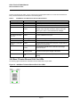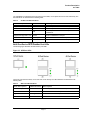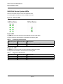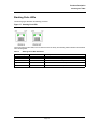
1
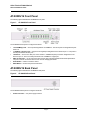
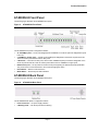
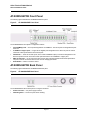
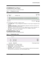
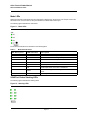
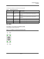
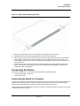
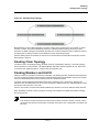
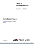
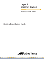
Layer 2
Ethernet Switch
Allied Telesis AT- 8000S
Switch Installation Guide
Allied Telesis AT- 8000S
Switch Installation Guide
Table of Contents
Table of Contents
Preface.................................................................................................................................... 4
How This Guide is Organized .......................................................................................................... 4
Document Conventions ................................................................................................................... 4
Product Description................................................................................................................. 6
Features .......................................................................................................................................... 7
IEEE Standards ............................................................................................................................... 7
AT-8000S/16 Front Panel................................................................................................................ 8
AT-8000S/16 Back Panel ................................................................................................................ 8
AT-8000S/24 Front Panel................................................................................................................ 9
AT-8000S/24 Back Panel ................................................................................................................ 9
AT-8000S/24POE Front Panel ...................................................................................................... 10
AT-8000S/24POE Back Panel....................................................................................................... 10
AT-8000S/48 Front Panel.............................................................................................................. 11
AT-8000S/48 Back Panel .............................................................................................................. 11
AT-8000S/48POE Front Panel ...................................................................................................... 12
AT-8000S/48POE Back Panel....................................................................................................... 12
Ports Description ........................................................................................................................... 13
10/100Base-T Fast Ethernet Ports ..........................................................................................................13
1000Base-T Gigabit Ethernet Ports.........................................................................................................13
SFP Port ..................................................................................................................................................13
DB-9 Console Port...................................................................................................................................13
LED Definitions .............................................................................................................................. 13
Front Panel LEDs ....................................................................................................................................13
Port LEDs ................................................................................................................................................15
24/48 Port Device System LEDs .............................................................................................................18
Stacking Ports LEDs................................................................................................................................19
Installation............................................................................................................................. 20
Preparing for Installation................................................................................................................ 20
Installation Precautions............................................................................................................................20
Site Requirements ...................................................................................................................................21
Unpacking................................................................................................................................................21
Installing the Device ...................................................................................................................... 22
Desktop or Shelf Installation ....................................................................................................................22
Rack Installation ......................................................................................................................................23
Connecting the Device .................................................................................................................. 24
Connecting the Switch to a Terminal .......................................................................................................24
AC Power Connection .............................................................................................................................24
Page 1
Allied Telesis AT-8000S Switch
Switch Installation Guide
Stacking ................................................................................................................................ 26
Understanding the Stack Topology ............................................................................................... 26
Stacking Chain Topology .............................................................................................................. 27
Stacking Members and Unit ID ..................................................................................................... 27
Configuring Stacking ..................................................................................................................... 28
Initial Configuration ............................................................................................................... 30
Configuration Overview................................................................................................................. 30
Configuration................................................................................................................................. 30
Static IP Address and Subnet Mask ....................................................................................................... 30
User Name.............................................................................................................................................. 31
Troubleshooting .................................................................................................................... 32
Technical Specifications ....................................................................................................... 34
Physical Specifications ........................................................................................................................... 34
Weight..................................................................................................................................................... 34
Environmental Specifications.................................................................................................................. 34
Power Specifications............................................................................................................................... 34
Safety and Electromagnetic Emissions Certifications............................................................................. 34
Compliance Standards............................................................................................................................ 35
Cable, Port, and Pinout Information........................................................................................................ 35
Pin Connections for the 10/100/1000 Ethernet Interface ........................................................................ 35
Translated Safety Statements............................................................................................... 38
Laser Safety Notices ..................................................................................................................... 38
Electrical Safety Notices ............................................................................................................... 38
Telecommunications Compliance Notices .................................................................................... 43
Page 2
Table of Contents
Page 3
Allied Telesis AT-8000S Switch
Installation Guide
Preface
This guide contains the hardware installation instructions for the AT-8000S/16, AT-8000S/24, AT-8000S/24POE,
AT-8000S/48 and AT-8000S/48POE Fast Ethernet Switches.
How This Guide is Organized
This manual contains the following chapters:
•
Chapter 1 Product Description describes the features and components of the switches.
•
Chapter 2 Installation describes the installation instructions for the switches.
•
Chapter 3 Stacking describes the stacking instructions for the switches.
•
Chapter 4 Initial Configuration describes the instructions for initially configuring the switches.
•
Chapter 5 Troubleshooting provides information on how to resolve problems that might occur with the
switches.
•
Appendix A Technical Specifications contain the technical specifications for the switches.
•
Appendix B Translated Safety Standards contain the safety standards for the device.
Document Conventions
This document uses the following conventions to highlight important information:
Note
Notes provide additional information.
Caution
Cautions inform you that performing or omitting a specific action may result in equipment damage or loss
of data.
Warning
Warnings inform you that performing or omitting a specific action may result in bodily injury.
Page 4
Contacting Allied Telesis
Contacting Allied Telesis
This section provides Allied Telesis contact information for technical support as well as sales or corporate
information.
Online Support
You can request technical support online by accessing the Allied Telesis Knowledge Base
from the following web site:
www.alliedtelesis.com/support. You can use the Knowledge Base to submit questions
to our technical support staff and review answers to previously asked questions..
Email and Telephone For Technical Support via email or telephone, refer to the Allied Telesis web site:
www.alliedtelesis.com. Select your country from the list displayed on the website. Then
Support
select the appropriate menu tab.
Returning Products
Products for return or repair must first be assigned a Return Materials Authorization (RMA)
number. A product sent to Allied Telesis without a RMA number will be returned to the
sender at the sender’s expense.
To obtain an RMA number, contact the Allied Telesis Technical Support group at our web
site: www.alliedtelesis.com/support/rma. Select your country from the list displayed on
the website. Then select the appropriate menu tab.
For Sales or
Corporate
Information
You can contact Allied Telesis for sales or corporate information at our web site:
www.alliedtelesis.com. Select your country from the list displayed on the website. Then
select the appropriate menu tab.
Warranty
The AT-8000S has a limited warranty of lifetime (two years PSU and fan).
Go to www.alliedtelesis.com/warranty for the specific terms and conditions of the warranty
and for warranty registration.
Page 5
Allied Telesis AT-8000S Switch
Switch Installation Guide
Chapter 1. Product Description
The new AT-8000S series combines the best of the previous L2 series; stackability and affordability.
The new AT-8000S series is an entry level managed switch for the SMB, Small Office/Field Office offering
managed desktop connectivity. The fiber uplink provides connectivity between workgroups over a larger
distances. In addition the AT-8000S series is also equipped with a copper 10/100/1000Base-T port for connectivity
to gigabit aggregation switches.
The new 8000S series combines value with the necessary management features for networked applications.
There are five device models which provide different hardware configurations and include the following:
•
AT-8000S/16 device which supports 16 built-in 10/100Base-T ports, and a Combo port functionality that
supports both copper and SFP interfaces.
•
AT-8000S/24 device with stacking ports which supports 24 built-in 10/100Base-T ports, 2G stackable and 2
Combo Ports, inclusive of a Combo port functionality that supports both copper and SFP interface.
•
AT-8000S/24POE device with stacking port which supports 24 built-in 10/100Base-T ports, 2G stackable and
2 Combo Ports, inclusive of a Combo port that supports both copper and SFP interface. The PoE function is
supported on RJ45 ports.
•
AT-8000S/48 device with stacking ports which supports 48 built-in 10/100Base-T ports, 2G stackable and 2
Combo Ports, inclusive of a Combo port functionality that supports both copper and SFP interface.
•
AT-8000S/48POE device with stacking port which supports 48 built-in 10/100Base-T ports, 2G stackable and
2 Combo Ports, inclusive of a Combo port that supports both copper and SFP interface. The PoE function is
supported on RJ45 ports.
The AT-8000S/24, AT-8000S/24POE, AT-8000S/48 and AT-8000S/48POE can be joined together into a stack of
up to six units. For more information, see Chapter 3 Stacking.
Device configuration is performed through an Embedded Web Server (EWS) or through a Command Line
Interface (CLI). The device management is performed through a DB-9 RS-232 interface.
Page 6
Product Description
Features
The AT-8000S/16, AT-8000S/24, AT-8000S/24POE, AT-8000S/48 and AT-8000S/48POE features include the
following:
•
•
•
•
•
•
•
•
•
•
•
•
•
•
•
•
•
•
•
•
•
•
•
•
•
•
•
Wirespeed switching traffic across all ports
Auto MDI/MDIX enabled
802.1d, 1w, 1s priority tags supported
Broadcast storm control
IEEE 802.1Q tagged VLANs supported
GARP/GVRP supported
Port/MAC based VLANs supported
802.3ad link aggregation Static and Dynamic (LACP) supported
IEEE 802.1P based QoS supported
Ingress rate limiting
Egress rate shaping (WRR)
802.1x port/MAC based authentication support
RFC 2618 RADIUS Authentication
SSL/ SSLv3
RFC 1492 TACACS+
Management ACL support
Industry standard CLI
Browser based management interface (HTTP)
Telnet access supported
SNMP v1, v2 and v3
RFC1757 RMON support
Port Mirroring support
PVE
Port Security
DHCP support
Static IP Multicast support
IGMP Snooping
IEEE Standards
–
–
–
–
–
–
IEEE 802.3 — 10Base-T
IEEE 802.3u — 100Base-TX
IEEE 802.3ab — 1000Base-TX Gigabit Ethernet
IEEE 802.3z — Full Duplex
IEEE 802.3u — Auto-Negotiation
IEEE 802.3x — Flow Control, Symmetric and Asymmetric
Page 7
Allied Telesis AT-8000S Switch
Switch Installation Guide
AT-8000S/16 Front Panel
The following figure illustrates the AT-8000S/16 front panel.
Figure 1:
AT-8000S/16 Front Panel
The AT-8000S/16 front panel is configured as follows:
•
•
•
•
•
•
16 10/100Mbps ports — RJ-45 ports designated as 10/100Base-T. The RJ-45 ports are designated as ports
Ports1-16.
1 1000Base-T Copper ports — Copper RJ-45 Gigabit port designated on the device as port 17. The port is a
Combo port linked to the SFP port.
1 SFP Port — There is one SFP port, which contains a 1000Base-X (fiber) connection designated on the
device as port 17. This is a Combo port linked to the 1000Base-T Copper port.
DB-9 Console port — An asynchronous serial console port supporting the RS-232 electrical specification.
The port is used to connect the device to the console managing the device.
Reset Button — Button to reset the device.
Mode Button — Selects the port LED indications.
AT-8000S/16 Back Panel
The following figure illustrates the AT-8000S/16 back panel.
Figure 2:
AT-8000S/16 Back Panel
The AT-8000S/16 back panel is configured as follows:
•
Power Connector — AC power supply interface.
Page 8
Product Description
AT-8000S/24 Front Panel
The following figure illustrates the AT-8000S/24 front panel.
Figure 3:
AT-8000S/24 Front Panel
The AT-8000S/24 front panel is configured as follows:
•
•
•
•
•
•
24 10/100Mbps ports — RJ-45 ports designated as 10/100Base-T. The RJ-45 ports are designated as ports
Ports1-24.
2 1000Base-T Copper ports — Copper RJ-45 Gigabit ports designated on the device as ports 25 and 26.
These are Combo ports linked to the two SFP ports.
2 SFP Ports — There are two SFP ports, which contain 1000Base-X (fiber) connections designated on the
device as ports 25 and 26. These are Combo ports linked to the two 1000Base-T Copper ports.
DB-9 Console port — An asynchronous serial console port supporting the RS-232 electrical specification.
The port is used to connect the device to the console managing the device.
Reset Button — Button to reset the device.
Mode Button — Selects the port LED indications.
AT-8000S/24 Back Panel
The following figure illustrates the AT-8000S/24 back panel.
Figure 4:
AT-8000S/24 Back Panel
The AT-8000S/24 back panel is configured as follows:
•
Power Connector — AC power supply interface.
•
2 Stacking Ports — Two RJ-45 ports device stacking.
Page 9
Allied Telesis AT-8000S Switch
Switch Installation Guide
AT-8000S/24POE Front Panel
The following figure illustrates the AT-8000S/24POE front panel.
Figure 5:
AT-8000S/24POE Front Panel
The AT-8000S/24POE front panel is configured as follows:
•
•
•
•
•
24 10/100Mbps ports — RJ-45 ports designated as 10/100Base-T. The RJ-45 ports are designated as ports
Ports1-24.
2 1000Base-T Copper ports — Copper RJ-45 Gigabit ports designated on the device as ports 25 and 26.
These are Combo ports linked to the two SFP ports.
2 SFP Ports — There are two SFP ports, which contain 1000Base-X (fiber) connections designated on the
device as ports 25 and 26. These are Combo ports linked to the two 1000Base-T Copper ports.
DB-9 Console port — An asynchronous serial console port supporting the RS-232 electrical specification.
The port is used to connect the device to the console managing the device.
Reset Button — Button to reset the device.
AT-8000S/24POE Back Panel
The following figure illustrates the AT-8000S/24POE back panel.
Figure 6:
AT-8000S/24POE Back Panel
The AT-8000S/24POE device back panel is configured as follows:
•
Power Connector — AC power supply interface.
•
2 Stacking Ports — Two RJ-45 ports device stacking.
Page 10
Product Description
AT-8000S/48 Front Panel
The following figure illustrates the AT-8000S/48 front panel.
Figure 7:
AT-8000S/48 Front Panel
The AT-8000S/48 device front panel is configured as follows:
•
•
•
•
48 10/100Mbps ports — RJ-45 ports designated as 10/100Base-T. The RJ-45 ports are designated as ports
Ports1-48.
2 1000Base-T Copper ports — Copper RJ-45 Gigabit ports designated on the device as ports 49 and 50.
These are Combo ports linked to the 2 SFP ports.
2 SFP Ports — There are two SFP ports, which contain 1000Base-X (fiber) connections designated on the
device as ports 49 and 50. These are Combo ports linked to the two 1000Base-T Copper ports.
Mode Button — Selects the port LED indications.
AT-8000S/48 Back Panel
The following figure illustrates the AT-8000S/48 back panel.
Figure 8:
AT-8000S/48 Back Panel
The AT-8000S/48 back panel is configured as follows:
•
Power Connector — AC power supply interface.
•
•
•
2 Stacking Ports — Two RJ-45 ports device stacking.
Reset Button — Button to reset the device.
DB-9 Console port — An asynchronous serial console port supporting the RS-232 electrical specification.
The port is used to connect the device to the console managing the device.
Page 11
Allied Telesis AT-8000S Switch
Switch Installation Guide
AT-8000S/48POE Front Panel
The following figure illustrates the AT-8000S/48POE front panel.
Figure 9:
AT-8000S/48POE Front Panel
The AT-8000S/48 device front panel is configured as follows:
•
•
•
48 10/100Mbps ports — RJ-45 ports designated as 10/100Base-T. The RJ-45 ports are designated as ports
Ports1-48.
2 1000Base-T Copper ports — Copper RJ-45 Gigabit ports designated on the device as ports 49 and 50.
These are Combo ports linked to the two SFP ports.
2 SFP Ports — There are two SFP ports, which contain 1000Base-X (fiber) connections designated on the
device as ports 49 and 50. These are Combo ports linked to the two 1000Base-T Copper ports.
AT-8000S/48POE Back Panel
The following figure illustrates the AT-8000S/48POE back panel.
Figure 10: AT-8000S/48POE Back Panel
The AT-8000S/48POE back panel is configured as follows:
•
Power Connector — AC power supply interface.
•
•
•
2 Stacking Ports — Two RJ-45 ports device stacking.
Reset Button — Button to reset the device.
DB-9 Console port — An asynchronous serial console port supporting the RS-232 electrical specification.
The port is used to connect the device to the console managing the device.
Page 12
Product Description
10/100Base-T Fast Ethernet Ports
Ports Description
10/100Base-T Fast Ethernet Ports
The 10/100Base-T Fast Ethernet ports are RJ-45. The 10/100 Mbps port supports half- and full-duplex mode.
1000Base-T Gigabit Ethernet Ports
The 24/48 port devices contains two Base-T Gigabit ports, and the 16 port device contains one Base-T Gigabit
port. The RJ-45 1000 Mbps port supports 1000 mbps in full-duplex mode and 10/100 mbps half- and full-duplex
mode.
SFP Port
Small Form Factor Pluggable (SFP) Optical Transceivers are integrated duplex data links for bi-directional
communication over optical fiber, designed for high-speed Fiber Channel data links. The SFP port is designated
as 1000Base-FX.
DB-9 Console Port
The DB-9 port is an asynchronous serial console port supporting the RS-232 electrical specification. The port is
used to connect the device to a console managing the device. This interface configuration is as follows:
•
•
•
•
Eight data bits.
One stop bit.
No parity.
Baud rate is 115,200 (default). The user can change the rate from 115,200 down to 2400 bps.
LED Definitions
The device front panels contain Light Emitting Diodes (LED) that indicate the device status. The different LED
types are as follows:
•
Port LEDs — Indicates each port status.
•
Power LED — Indicates the device power supply status.
•
Mode LEDs — Indicates which information the LED displays - only on non-PoE devices.
•
Stacking LEDs — Indicates the device location in a stack.
Front Panel LEDs
The front panels have two types of LEDs, excluding the LEDs attached to the ports. The two types are as follows:
•
•
Mode LEDs — Indicates which information the LED displays.
Stacking LEDs — Indicates the device location in a stack.
Page 13
Allied Telesis AT-8000S Switch
Switch Installation Guide
Mode LEDs
Selecting a particular mode determines what information is displayed on the port LED. For example, if the mode
selected is "COL", then the LED on each port indicates the collision status of that port.
The following figure illustrates the mode LEDs.
Figure 11: Mode LEDs
The mode LED indications are described in the following table:
Table 1:
Mode LED Indications
LED Des criptio n
L ED In dica tio n
D escr ip tio n
COL
Green
Data collisions are occurring on the port.
Off
No data collisions are occurring on the port.
Green
Link is established at 100Mbps.
Off
Link is established in 10Mbps.
Green
A Full Duplex mode connection is established.
Off
A Half Duplex mode connection is established.
Green
Port is transmitting and/or receiving data. This the default
mode.
Off
No activity is established.
SPD
FDX
ACT
24/48 Port Device Stacking LEDs
The following figure illustrates the stacking LEDs.
Figure 12: Stacking LEDs
Page 14
Product Description
Port LEDs
The stacking LED indications are described in the following table:
Table 2:
Stacking LED Indications
LED D e s c r i pt i on
LE D I n di c a t i on
De s c r i pt i on
All LEDs off
The device is operating as a standalone switch.
Green
The device is master-enabled, and is either the master or backup
of the stack, which is determined by the master election
algorithm.
Green
The device is master-enabled, and is either the master or backup
of the stack, which is determined by the master election
algorithm.
S3
Green
The device is operating as Stack Member 3 in the stack.
S4
Green
The device is operating as Stack Member 4 in the stack.
S5
Green
The device is operating as Stack Member 5 in the stack.
S6
Green
The device is operating as Stack Member 6 in the stack.
S1
S2
Port LEDs
10/100 Base-T Fast Ethernet RJ-45 Port LEDs
The following figure illustrates the port LEDs.
Figure 13: 10/100Base-T Fast Ethernet RJ-45 Port LEDs
Page 15
Allied Telesis AT-8000S Switch
Switch Installation Guide
The RJ-45 ports have two LEDs, one for Link and one for activity (Mode status for non PoE and Load status for
PoE). The LED indications are described in the following table:
Table 3:
10/100Base-T Fast Ethernet RJ-45 Port LED Indications
Por t Des criptio n
L ED In dica tio n
D escr ip tio n
Left LED - Link
Green
A 100-Mbps link is established on the port.
Off
No link is established on the link.
Green
This indication is determined by the mode selected. For
example if the mode SPD is selected, and the port mode
LED is green, there is a link established at 100Mbps.
Off
This indication is determined by the mode selected.
Green
A link is established on the port.
Flashing green
Port is transmitting and/or receiving data.
Off
No link is established on the port.
Green
The port detects a Power Device (PD) and complies with the
condition of a normal load.
Amber
An overload, a terminal short or external forced voltage
feeds into the port.
Flashing amber
The port detects a PD but the power provided to it exceeds
the maximum POE power budget of the switch.
Off
No PD is connected, and subsequently there is no power
feeding.
Right LED - Mode
Left LED (PoE model) Link / Act
Right LED - POE (PoE
model)
1000 Base-T/Combo Ethernet RJ-45 Port LEDs
The following figure illustrates the 1000 Base-T/Combo Ethernet RJ-45 port LEDs.
Figure 14: 1000 Base-T/Combo Ethernet RJ-45 Port LEDs
Page 16
Product Description
Port LEDs
The 1000 Base-T/Combo Ethernet RJ-45 ports have two LEDs, one for speed and one for Link and activity. The
LED indications are described in the following table:
Table 4:
Combo Port LED Indications
P or t D e s c r i pt i o n
LE D I nd ic a t i on
D e s c r i p t io n
Copper Port Left LED - Speed
Green
A 1000-Mbps link is established on the port.
Amber
A 100-Mbps link is established on the port.
Off
A 10-Mbps Link is established on the port / No link
established.
Green
A link is established on the port.
Flashing Green
There is data transmission on the port.
Off
There is no data transmission on the port.
Copper Port Right LED - Link
24/48 Port Device SFP/Combo Port LEDs
The following figure illustrates the SFP/Combo port LEDs.
Figure 15: SFP Port LEDs
The RJ-45 ports have two LEDs, one for Link and one for activity. The LED indications are described in the
following table:
Table 5:
SFP Port LED Indications
Por t Des criptio n
L ED In dica tio n
D escr ip tio n
Left LED - Speed
Green
A 1000-Mbps link is established on the port.
Off
No link is established on the port.
Flashing Green
A link is established on the port.
Off
No link is established on the link.
Right Link / ACT LED
Page 17
Allied Telesis AT-8000S Switch
Switch Installation Guide
24/48 Port Device System LEDs
There are two system LEDs, the Power and Diagnostics LEDs.
The following figure illustrates the Power and Diagnostics LEDs.
Figure 16: SFP Port LEDs
Power LED
The PWR LED on the front panel of the device indicates the power supply status.
The power supply port LED indications are described in the following table:
Table 6:
Power Supply LED Indications
LED Des criptio n
L ED In dica tio n
D escr ip tio n
Power
Off
The system is not powered up (power off).
Green
Main power is functional (normal operation).
Diagnostic LED
The DIAG LED on the front panel of the device indicates the diagnostics results.
The diagnostics LED indications are described in the following table:
Table 7:
Diagnostics LED Indications
LED Des criptio n
L ED In dica tio n
D escr ip tio n
DIAG
Flashing green
System diagnostics has failed.
Green
System diagnostics successfully completed.
Page 18
Product Description
Stacking Ports LEDs
Stacking Ports LEDs
The following figure illustrates the Stacking port LEDs.
Figure 17: Stacking Port LEDs
The RJ-45 ports have two LEDs, one is for link and one is for activity. The Stacking LEDs indications are described
in the following table:
Table 8:
Stacking Ports LEDs Indications
Por t D escr ip tio n
L ED In dica tio n
D escr ip tio n
Left LED - Link
Green
A link is established on the port.
Off
No link is established on the port.
Green
There is data transmission on the port.
Off
No link is established on the port.
Right LED - Act
Page 19
Allied Telesis AT-8000S Switch
Switch Installation Guide
Chapter 2. Installation
This section contains information for installing the device, and includes the following sections:
•
•
•
•
Preparing for Installation
Installing the Device
Connecting the Device
Rack Installation
Preparing for Installation
This section provides an explanation for preparing the installation site, and includes the following topics:
•
•
•
Preparing for Installation
Site Requirements
Unpacking
Safety Precautions
Please review the following safety precautions before you begin to install the AT-8000S.
Note
The indicates that a translation of the safety statement is available in a PDF document titled
“Translated Safety Statements” on the Allied Telesis website at www.alliedtelesis.com and on the
documentation CD shipped with this product.
Warning
Class 1 Laser product. L1
Warning
Do not stare into the laser beam. L2
Warning
To prevent electric shock, do not remove the cover. No user-serviceable parts inside. This unit contains
hazardous voltages and should only be opened by a trained and qualified technician. To avoid the
possibility of electric shock, disconnect electric power to the product before connecting or disconnecting
the LAN cables. E1
Page 20
Installation
Preparing for Installation
Warning
Do not work on equipment or cables during periods of lightning activity. E2
Warning
Power cord is used as a disconnection device. To de-energize equipment, disconnect the power cord. E3
Warnings
•
•
Class I Equipment. This equipment must be earthed. The power plug must be connected to a properly
wired earth ground socket outlet. An improperly wired socket outlet could place hazardous voltages
on accessible metal parts. E4
Pluggable Equipment. The socket outlet shall be installed near the equipment and shall be easily
accessible. E5
Caution
Air vents must not be blocked and must have free access to the room ambient air for cooling. E6
Warnings
•
•
Operating Temperature. This product is designed for a maximum ambient temperature of 40° degrees
C. E7
All Countries: Install product in accordance with local and National Electrical Codes. E8
Cautions
•
•
The attached mounting brackets must be used to securely mount the device on the wall. E15
Circuit Overloading: Consideration should be given to the connection of the equipment to the supply
circuit and the effect that overloading of circuits might have on overcurrent protection and supply
wiring. Appropriate consideration of equipment nameplate ratings should be used when addressing
this concern. E21
Warnings
•
•
Mounting of the equipment in the rack should be such that a hazardous condition is not created due
to uneven mechanical loading. E25
If installed in a closed or multi-unit rack assembly, the operating ambient temperature of the rack
environment may be greater than the room ambient temperature. Therefore, consideration should be
given to installing the equipment in an environment compatible with the manufacturer’s maximum
rated ambient temperature (Tmra). E35
Page 21
Allied Telesis AT-8000S Switch
Switch Installation Guide
Caution
Installation of the equipment in a rack should be such that the amount of air flow required for safe operation
of the equipment is not compromised. E36
Warning
Reliable earthing of rack-mounted equipment should be maintained. Particular attention should be given
to supply connections other than direct connections to the branch circuits (e.g., use of power strips). E37
Warning
To reduce the risk of electric shock, the PoE ports on this product must not connect to cabling that is routed
outside the building where this device is located. E40
Site Requirements
The device should be placed on a table-top. Before installing the unit, verify that the location chosen for installation
meets the following site requirements.
•
General — Ensure that the power supply is correctly installed.
•
Power — The unit is installed within 1.5 m (5 feet) of a grounded, easily accessible outlet 100-250V AC, 5060Hz.
•
Clearance — There is adequate frontal clearance for operator access. Allow clearance for cabling, power
connections, and ventilation.
•
Cabling — The cabling is routed to avoid sources of electrical noise such as radio transmitters, broadcast
amplifiers, power lines, and fluorescent lighting fixtures.
•
Ambient Requirements — The ambient unit operating temperature range is 0 to 40ºC (32 to 104ºF) at a
relative humidity of up to 95%, non-condensing. Verify that water or moisture cannot enter the device casing.
Unpacking
This section contains information for unpacking the device, and includes the following topics:
•
•
Package Contents
Unpacking Essentials
Package Contents
While unpacking the device, ensure that the following items are included:
•
One AT- 8000S/xx series unit
•
Rubber Feet for desktop installation
•
Rack-mount kit hardware accessories
•
An AC power cable
•
Stacking cable (Yellow color)
•
Console RS-232 cable with DB-9 connector
•
Installation guide on CD
Page 22
Installation
Installing the Device
Unpacking Essentials
Note
Before unpacking the device, inspect the package and report any evidence of damage immediately.
To unpack the device perform the following:
1. It is recommended to put on an ESD wrist strap and attach the ESD clip to a metal surface to act as ground.
An ESD strap is not supplied with the device.
2. Place the container on a clean flat surface and cut all straps securing the container.
3. Open the container.
4. Carefully remove the device from the container and place it on a secure and clean surface.
5. Remove all packing material.
6. Inspect the product for damage. Report any damage immediately.
If any item is found missing or damaged, please contact your local ATI reseller for a replacement.
Installing the Device
The device can be installed on a flat surface or mounted in a rack. This section includes the following topics:
•
•
Desktop or Shelf Installation
Rack Installation
Desktop or Shelf Installation
When installing the switch on a desktop or shelf, the rubber feet included with the device should first be attached.
Attach these cushioning feet on the bottom at each corner of the device.
Ensure the surface is be able to support the weight of the device and the device cables.
To install the device on a surface, perform the following:
1. Attach the rubber feet on the bottom of the device. The following figure illustrates the rubber feet installation
on the device.
Page 23
Allied Telesis AT-8000S Switch
Switch Installation Guide
Figure 18: Installing Rubber Feet
2.
3.
Set device down on a flat surface, while leaving 2 inches on each side and 5 inches at the back.
Ensure that the device has proper ventilation by allowing adequate space for ventilation between the device
and the objects around the device.
Rack Installation
The device can be mounted in an EIA standard-sized, 19-inch rack, which can be placed in a wiring closet with
other equipment. To install the device the mounting brackets must first be attached to the device’s sides.
Notes
• Disconnect all cables from the unit before mounting the device in a rack or cabinet.
• When mounting multiple devices into a rack, mount the devices from the bottom up.
To install the device in a rack, perform the following:
1. It is recommended to put on an ESD wrist strap and attach the ESD clip to a metal surface to act as ground.
An ESD strap is not supplied with the device.
2. Place the device on a flat and stable surface.
3. Place the supplied rack-mounting bracket on one side of the device ensuring the mounting holes on the
device line up to the mounting holes on the rack mounting bracket. The following figure illustrates where the
mounting brackets are placed on the device.
Page 24
Installation
Connecting the Device
Figure 19: Attaching the Mounting Brackets
4.
5.
6.
7.
Insert the supplied screws into the rack mounting holes and tighten with a screwdriver.
Repeat the process for the rack-mounting bracket on the other side of the device.
Insert the device into the 19-inch rack and secure the unit to the rack with the rack screws (not provided by
the ATI supplier). When securing, fasten the lower pair of screws before the upper pair of screws. This
ensures that the weight of the unit is evenly distributed during installation. Ensure that the ventilation holes
are not obstructed.
Secure the unit to the rack with the rack screws. Fasten the lower pair of screws before the upper pair of
screws. This ensures that the weight of the unit is evenly distributed during installation. Ensure that the
ventilation holes are not obstructed.
Connecting the Device
This section describes how to connect the device, and includes the following sections:
•
Connecting the Switch to a Terminal
•
AC Power Connection
Connecting the Switch to a Terminal
The device is connected to a terminal through a console port on the front panel of the 16 port device and the back
panel for the 24/48 port devices. The console connection which enables a connection to a terminal desktop
system running a terminal emulation software for monitoring and configuring the device.
The terminal must be a VT100 compatible terminal or a desktop or portable system with a serial port and running
VT100 terminal emulation software.
Page 25
Allied Telesis AT-8000S Switch
Switch Installation Guide
To connect a terminal to the device Console port, perform the following:
1. Connect a cable to the terminal running VT100 terminal emulation software.
2. Ensure that the terminal emulation software is set as follows:
a) Select the appropriate port to connect to the device.
b) Set the data rate to 115,200 baud.
c) Set the data format to 8 data bits, 1 stop bit, and no parity.
d) Set flow control to none.
e) Under Properties, select VT100 for Emulation mode.
f) Select Terminal keys for Function, Arrow, and Ctrl keys. Ensure that the setting is for Terminal keys (not
Windows keys).
Note
When using HyperTerminal with Microsoft Windows 2000, ensure that you have Windows 2000 Service
Pack 2 or later installed. With Windows 2000 Service Pack 2, the arrow keys function properly in
HyperTerminal’s VT100 emulation. Go to www.microsoft.com for information on Windows 2000 service
packs.
3.
Connect the cable to the console port on the device front panel.
AC Power Connection
To connect the power supply perform the following:
1. Using a 5-foot (1.5 m) standard power cable with safety ground connected, insert the power cable to the AC
main socket located on the back panel.
2. Connect the power cable to a grounded AC outlet.
3. Confirm that the device is connected and operating by checking that the Power Supply LED on the front panel
is green.
Page 26
Installation
Connecting the Device
Page 27
Allied Telesis AT-8000S Switch
Installation Guide
Chapter 3. Stacking
Stacking provides multiple switch management through a single point as if all stack members are a single unit. All
stack members are accessed via a single IP address through which the stack is managed. The stack can be
managed from the following:
•
•
Embedded Web-based Interface
Command Line Interface (CLI)
Devices support stacking up to six units per stack, or can operate as stand-alone units.
During the Stacking setup, one switch is selected as the Stacking Master and another stacking member can be
selected as the Backup Master. All other devices are selected as stack members. All stack units are assigned a
unique Unit ID.
Switch software can be downloaded for the entire stack unit or separately for each stack member . However, all
units in the stack must be running the same software version.
Switch stacking and configuration is maintained by the Stacking Master. The Stacking Master detects and
reconfigures the ports with minimal operational impact in the event of:
•
•
•
•
Unit Failure
Inter-unit Stacking Link Failure
Unit Insertion
Removing a Stacking Unit
This section provides an introduction to the user interface, and includes the following topics:
•
•
•
•
Understanding the Stack Topology
Stacking Chain Topology
Stacking Members and Unit ID
Configuring Stacking
Understanding the Stack Topology
Stacked devices operate in a Ring topology. A Ring topology is where all devices in the stack are connected to
each other forming a circle. Each stacked device accepts data and sends it to the device to which it is physically
connected. The packet continues through the stack until it reaches the destination port. The system automatically
discovers the optimal path on which to send traffic.
Page 26
Stacking
Stacking Chain Topology
Figure 20: Stacking Ring Topology
Most difficulties incurred in Ring topologies occur when a device in the ring becomes non-functional, or a link is
severed. In a stack, the system automatically switches to a Stacking Failover topology without any system
downtime. An SNMP message is automatically generated, but no stack management action is required. However,
the stacking link or stacking member must be repaired to ensure the stacking integrity.
After the stacking issues are resolved, the device can be reconnected to the stack without interruption, and the
Ring topology is restored.
Stacking Chain Topology
If a failure occurs in the stacking topology, the stack reverts to Chain Stacking Topology. In the Chain topology,
devices operate in a chain formation. The Stacking Master determines where the packets are sent. Each unit is
connected to two neighboring devices, except for the top and bottom units.
Stacking Members and Unit ID
Stacking Unit IDs are essential to the stacking configuration. The stacking operation is determined during the boot
process. The Operation Mode is determined by the Unit ID selected during the initialization process. For example,
if the user selected stand-alone mode, the device boots as a stand-alone device.
The device units are shipped with the default Unit ID of the stand-alone unit. If the device is operating as a
standalone unit, all stacking LEDs are off. Once the user selects a different Unit ID, the default Unit ID not erased,
and remains valid, even if the unit is reset.
Unit ID 1 and Unit ID 2 are reserved for Master enabled units. Unit IDs 3 to 6 can be defined for stack members.
When the Master unit boots or when inserting or removing a stack member, the Master unit initiates a stacking
discovering process.
Note
If two members are discovered with the same Unit ID the stack continues to function, however only the
unit with the older join time joins the stack. A message is sent to the user, notifying that a unit failed to join
the stack.
Page 27
Allied Telesis AT-8000S Switch
Installation Guide
Configuring Stacking
Configuring stacking is performed during the bootup process. To configure a device as part of a stack, the bootup
process must be interrupted straight after the Power On Self Test (POST).
To configure the device for stacking, perform the following:
1.
2.
3.
4.
Ensure that the device console is connected to a VT100 terminal device or VT100 terminal emulator.
Deactivate the AC power receptacle.
Connect the device to the AC receptacle.
Activate the AC power receptacle.
When the power is turned on with the local terminal already connected, the switch goes through POST. POST
runs every time the device is initialized and checks hardware components to determine if the device is fully
operational before completely booting. If a critical problem is detected, the program flow stops. If POST
passes successfully, a valid executable image is loaded into RAM. POST messages are displayed on the
terminal and indicate test success or failure.
As the switch boots, the bootup test first counts the device memory availability and then continues to boot.
The following screen is an example of the displayed POST.
------ Performing the Power-On Self Test (POST) -----UART Channel Loopback Test........................PASS
Testing the System SDRAM..........................PASS
Boot1 Checksum Test...............................PASS
Boot2 Checksum Test...............................PASS
Flash Image Validation Test.......................PASS
BOOT Software Version x.x.x.xx Built 07-Jan-200x 10:53:05
Processor: xxxxxx xxxxx xxxx, xx MByte SDRAM.
I-Cache 8 KB. D-Cache 8 KB. Cache Enabled.
Autoboot in 2 seconds - press RETURN or Esc. to abort and enter prom.
The boot process runs approximately 30 seconds.
The auto-boot message that appears at the end of POST (see the last lines) indicates that no problems were
encountered during boot.
5.
Suspend the startup process by pressing <Esc> or <Enter> within two seconds and the following message is
displayed:
Autoboot in 2 seconds -press RETURN or Esc.to abort and enter prom.
Page 28
Stacking
Configuring Stacking
The Startup Menu is displayed and contains the following configuration functions:
Startup Menu
[1] Download Software
[2] Erase Flash File
[3] Password Recovery Procedure
[4] Enter Diagnostic Mode
[5] Set Terminal Baud-Rate
[6] Stack menu
[7] Back
Enter your choice or press 'ESC' to exit:
6.
From the Startup Menu, press “6”.
The following prompt is displayed:
Stack menu
[1] Show unit stack id
[2] Set unit stack id
[3] Set unit working mode
[4] Back
Enter your choice or press 'ESC' to exit:
7.
From the Stack Menu, press “2”.
The following prompt is displayed:
Enter your choice or press 'ESC' to exit:
Enter unit stack id [0-6]:
8.
Enter the unit stack number. Note that Units 1 and 2 are master-enabled units. One of them will be elected as
Stack Master. Therefore, at least one unit in the stack must be designated as either Unit 1 or Unit 2.
9. Press <Enter>. The device is defined within the stack.
10. From the Stack menu, press “3”. The Following prompt is displayed:
Enter unit working mode [1 - standalone, 2 - stacking]:
11. From the Startup menu, press “7”. The Startup menu is closed and the device continues the Startup process.
Note
Once the device is booted up and operational in the stack, the configuration can be modified through the
Web or CLI.
Page 29
Allied Telesis AT-8000S Switch
Installation Guide
Chapter 4. Initial Configuration
Configuration Overview
Before assigning a static IP address to the device, obtain the following information from the network administrator:
•
•
A specific IP address allocated by the network administrator for the switch to be configured
Network mask for the network
There are two types of configuration: Initial configuration consists of configuration functions with basic security
considerations, whereas advanced configuration includes dynamic IP configuration and more advanced security
considerations.
After making any configuration changes, the new configuration must be saved before rebooting. To save the
configuration, enter the following CLI command:The following prompt is displayed:
Console# copy running-config startup-config
Configuration
The initial configuration, which starts after the device has booted successfully, includes static IP address and
subnet mask configuration, and setting user name and privilege level to allow remote management. If the device is
to be managed from an SNMP-based management station, SNMP community strings must also be configured.
The following configurations are completed:
•
•
Static IP Address and Subnet Mask
User Name
Static IP Address and Subnet Mask
IP interfaces can be configured on each port of the device. After entering the configuration command, it is
recommended to check if a port was configured with the IP address by entering the “show ip interface” command.
The commands to configure the device are port specific.
To manage the switch from a remote network, a default gateway must be configured, which is an IP address to
where packets are sent when the destination is within another network. The configured gateway address must
belong to the same subnet as the IP interface of the device.
To configure the default gateway, enter the required commands at the system prompt as shown in the following
configuration example where 101.101.101.101 is the specific management station, and 100.1.1.254 is the default
gateway:
console#
console# configure
console(config)# interface vlan 1
console(config-if)# ip address 100.1.1.1 255.255.0.0
console(config-if)# exit
console(config)# ip default-gateway 100.1.1.254
console(config)# exit
Page 30
Initial Configuration
Configuration
Note
100.1.1.254 is the IP address of the default gateway that is used to reach the management network
101.101.0.0.
To check the configuration, enter the command “show ip interface” as illustrated in the following example.
Console# show ip interface
Gateway IP Address
Activity Status
Type
-----------------------------
----------------
---------
100.1.1.254
active
static
IP Address
I/F
Type
-----------------------------
----------------
---------
100.1.1.1/16
vlan 1
static
User Name
A user name is used to manage the device remotely, for example through SSH, Telnet, or the Web interface. To
gain complete administrative (super-user) control over the device, the highest privilege (15) must be specified.
Note
Only an administrator (super-user) with the highest privilege level (15) is allowed to manage the device
through the Web browser interface.
For more information about the privilege level, see the CLI Reference Guide.
The configured user name is entered as a login name for remote management sessions. To configure user name
and privilege level, enter the command at the system prompt as shown in the configuration example:
Console> enable
Console# configure
Console(config)# username admin password lee privilege 15
Page 31
Allied Telesis AT-8000S Switch
Installation Guide
Chapter 5. Troubleshooting
This chapter contains information on how to troubleshoot the switch in the event that a problem occurs.
Note
If you are still unable to resolve the problem after following the instructions in this chapter, contact ATI
Technical Support for assistance.
Device not operating correctly
Check the PWR LED on the front of the switch. If the LED is OFF, indicating that the unit is not receiving power, do
the following:
•
Ensure that the power cord is securely connected to the power source and to the AC connector on the back
panel of the switch.
•
Verify that the power outlet has power by connecting another device to it.
•
Try connecting the unit to another power source.
•
Try using a different power cord.
•
Verify that the voltage from the power source is within the required levels for your region.
•
Verify that the LNK/ACT LED for each port is ON. If a LNK/ACT LED is OFF, do the following:
•
Verify that the end-node connected to the port is powered ON and is operating properly.
•
Verify that the twisted pair cable is securely connected to the port on the switch and to the port on the endnode.
•
Ensure that the twisted pair cable does not exceed 100 meters (328 feet).
•
Verify that you are using Category 5 twisted pair cable.
Cannot connect using Telnet, Web browser, or SNMP software
•
Be sure the switch is powered up.
•
Check network cabling between the management station and the switch.
•
Check that you have a valid network connection to the switch and that the port you are using has not been
•
•
•
•
disabled.
Be sure you have configured the VLAN interface through which the management station is connected with a
valid IP address, subnet mask and default gateway.
Be sure the management station has an IP address in the same subnet as the switch’s IP interface to which it
is connected.
If you are trying to connect to the switch via the IP address for a tagged VLAN group, your management
station, and the ports connecting intermediate switches in the network, must be configured with the
appropriate tag.
If you cannot connect using Telnet, you may have exceeded the maximum number of concurrent Telnet/SSH
sessions permitted. Try connecting again at a later time.
Forgot or lost the password
Contact ATI Technical Support for assistance.
Page 32
Troubleshooting
Page 33
Allied Telesis AT-8000S Switch
Installation Guide
Appendix A. Technical Specifications
Physical Specifications
The different devices have the following physical specifications:
•
AT-8000S/16 + 1G — 330 x 230.5 x 43.2 mm (W x D x H)
•
AT-8000S/24 + 2G — 440 x 257 x 43.2 mm (W x D x H)
•
AT-8000S/24 + 2G w/ POE — 440 x 257 x 43.2 mm (W x D x H)
•
AT-8000S/48 + 2G — 440 x 257 x 43.2 mm (W x D x H)
•
AT-8000S/48 + 2G w/ POE — 440 x 387 x 43.2 mm (W x D x H)
Weight
•
•
•
AT-8000S/16 —1.95kg
AT-8000S/24 — 3.15kg
AT-8000S/48 — 3.38kg
Environmental Specifications
•
•
•
•
•
Operating temperature — 0° to 40°
Storage temperature — 20° to 70°
Operating Humidity — 5% to 80% non-condensing
Storage Humidity — 5% to 95% non-condensing
Altitude — max 3000m (9,843ft)
Power Specifications
Power Supply for Non-POE model
100-240VAC/50-60 Hz universal input
Power Supply for POE Model
•
225W Power Supply
– Input: 100-240VAC/50-60 Hz universal inputs
– Output: 50V/180W for POE, 12V/45W per Switch
•
465W Power Supply
– Input: 100-240VAC/50-60 Hz universal inputs
– Output: 50V/375W for POE, 12V/90W per Switch
Safety and Electromagnetic Emissions Certifications
CE Class A, FCC Class A, VCCI Class A
Page 34
Technical Specifications
Compliance Standards
The devices conform to the following complience standards:
•
•
•
•
The Environmental standard, per ATI QLT 1220
RoHS compliant
The EN50082-1 immunity standard
The following safety standards:
–
–
–
–
UL1950
–
–
–
–
FCC Class A
CSA22.2 no.950
TUV (EN60950)
CE
The following EMI/Emission standards:
•
EN55022 Class A
VCCI Class A
C-TICK
Cable, Port, and Pinout Information
This section describes the devices physical interfaces and provides information about cable connections. Stations
are connected to the device ports through the physical interface ports on the front panel. For each station, the
appropriate mode (Half/Full Duplex, Auto) is set.
Pin Connections for the 10/100/1000 Ethernet Interface
The switching port can connect to stations wired in standard RJ-45 Ethernet station mode using straight cables.
Transmission devices connected to each other use crossed cables. The following figure illustrates the pin
allocation.
Figure 21: RJ-45 Pin Allocation
The following table describes the pin allocation
Table 9:
RJ-45 Pin Connections for 10/100/1000 Base-T
Pin
U se
1
TxRx 1+
2
TxRx 1-
Page 35
Allied Telesis AT-8000S Switch
Installation Guide
Table 9:
RJ-45 Pin Connections for 10/100/1000 Base-T
Pin
U se
3
TxRx 2+
4
TxRx 3+
5
TxRx 3-
6
TxRx 2-
7
TxRx 4+
8
TxRx 4-
Page 36
Technical Specifications
Page 37
Allied Telesis AT-8000S Switch
Installation Guide
Appendix B. Translated Safety Statements
Important: This appendix contains multiple-language translations for the safety statements in this guide.
Wichtig: Dieser Anhang enthält Übersetzungen der in diesem Handbuch enthaltenen Sicherheitshinweise in
mehreren Sprachen.
Importante: Este apéndice contiene traducciones en múltiples idiomas de los mensajes de seguridad incluidos
en esta guía.
Important: Cette annexe contient la traduction en plusieurs langues des instructions de sécurité figurant dans ce
guide.
Importante: Questa appendice contiene traduzioni in più lingue degli avvisi di sicurezza di questa guida.
Laser Safety Notices
Warning
1. Class 1 Laser product.
Warning
2. Do not stare into the laser beam.
Electrical Safety Notices
Warning
1.Class 1 Laser product.
Warning
2. Do not stare into the laser beam.
Warning
3. To prevent electric shock, do not remove the cover. No user-serviceable parts inside. This unit contains
hazardous voltages and should only be opened by a trained and qualified technician. To avoid the
possibility of electric shock, disconnect electric power to the product before connecting or disconnecting
the LAN cables.
Warning
4. Do not work on equipment or cables during periods of lightning activity.
Page 38
Translated Safety Statements
Electrical Safety Notices
Warning
5. Power cord is used as a disconnection device. To de-energize equipment, disconnect the power cord.
Warning
6. Class I Equipment. This equipment must be earthed. The power plug must be connected to a properly
wired earth grounded socket outlet. An improperly wired socket outlet could place hazardous voltages on
accessible metal parts.
Warning
7. Pluggable Equipment. The socket outlet shall be installed near the equipment and shall be easily
accessible.
Caution
8. Air vents must not be blocked and must have free access to the room ambient air for cooling.
Warning
9. Operating Temperature. This product is designed for a maximum ambient temperature of 40° degrees
C.
Warning
10. All Countries: Install product in accordance with local and National Electrical Codes.
Warning
11. As a safety precaution, install a circuit breaker with a minimum value of 15 Amps between the
equipment and the DC power source.
Warning
12. Always connect the wires to the LAN equipment first before you connect the wires to the circuit
breaker. Do not work with HOT feeds to avoid the danger of physical injury from electrical shock. Always
be sure that the circuit breaker is in the OFF position before connecting the wires to the breaker.
Page 39
Allied Telesis AT-8000S Switch
Installation Guide
Warning
13. Do not strip more than the recommended amount of wire. Stripping more than the recommended
amount can create a safety hazard by leaving exposed wire on the terminal block after installation.
Warning
14. When installing this equipment, always ensure that the frame ground connection is installed first and
disconnected last.
Warning
15. Check to see if there are any exposed copper strands coming from the installed wire. When this
installation is done correctly there should be no exposed copper wire strands extending from the terminal
block. Any exposed wiring can conduct harmful levels of electricity to persons touching the wires.
Warning
17. This system works with positive grounded or negative grounded DC systems.
Warning
18. Only trained and qualified personnel are allowed to install or to replace this equipment.
Caution
19. The attached mounting brackets must be used to securely mount the device on the wall.
Caution
20. Do not install in direct sunlight, or a damp or dusty place.
Caution
21. Do not expose the gateway device to moisture or water.
Caution
22. If the gateway device is installed indoors, make sure that the site is a dust free environment. The site
should provide for easy access to the ports of the gateway device.This will make it easy for you to connect
and disconnect cables, as well as view the LEDs.
Page 40
Translated Safety Statements
Electrical Safety Notices
Warning
23. The power source for the gateway unit should be located near the unit and should be easily accessible.
Caution
24. To allow proper cooling of the gateway device, make sure that the air flow around the unit and through
its heatsink cooling fins on the rear is not restricted.
Caution
25. Circuit Overloading: Consideration should be given to the connection of the equipment to the supply
circuit and the effect that overloading of circuits might have on overcurrent protection and supply wiring.
Appropriate consideration of equipment nameplate ratings should be used when addressing this concern.
Caution
26. Risk of explosion if battery is replaced by an incorrect type. Replace only with the same or equivalent
type recommended by the manufacturer. Dispose of used batteries according to the manufacturer’s
instructions.
Attention: Le remplacement de la batterie par une batterie de type incorrect peut provoquer un danger
d’explosion. La remplacer uniquement par une batterie du même type ou de type équivalent recommandée par le
constructeur. Les batteries doivent être éliminées conformément aux instructions du constructeur.
Warning
27. For centralized DC power connection, install only in a restricted access area.
Warning
28. A tray cable is required to connect the power source if the unit is powered by centralized DC power.
The tray cable must be a UL listed Type TC tray cable and rated at 600 V and 90 degrees C, with three
conductors, minimum 14 AWG.
Warning
29. Mounting of the equipment in the rack should be such that a hazardous condition is not created due
to uneven mechanical loading.
Page 41
Allied Telesis AT-8000S Switch
Installation Guide
Warning
30. Remove all metal jewelry, such as rings and watches, before installing or removing a line card from a
powered-on chassis.
Warning
31. Use dedicated power circuits or power conditioners to supply reliable electrical power to the device.
Warning
32. The chassis may be heavy and awkward to lift. Allied Telesis recommends that you get assistance
when mounting the chassis in an equipment rack.
Warning
33. Do not look directly at the fiber optic cable ends or inspect the cable ends with an optical lens.
Warning
34. This unit might have more than one power cord. To reduce the risk of electric shock, disconnect all
power cords before servicing the unit.
Warning
35. The power input must be provided from SELV source only, per IEC 60950. Do not connect to a
centralized DC battery bank.
Caution
36. UL recognized wires of 18 AWG minimum should be provided by the installer.
Caution
37. UL recognized wires of 22 AWG minimum should be provided by the installer.
Caution
38. Power to the hub must be sourced only from the adapter.
Page 42
Translated Safety Statements
Telecommunications Compliance Notices
Caution
39. If installed in a closed or multi-unit rack assembly, the operating ambient temperature of the rack
environment may be greater than the room ambient temperature. Therefore, consideration should be
given to installing the equipment in an environment compatible with the manufacturer’s maximum rated
ambient temperature (Tmra).
Caution
40. Installation of the equipment in a rack should be such that the amount of air flow required for safe
operation of the equipment is not compromised.
Warning
41. Reliable earthing of rack-mounted equipment should be maintained. Particular attention should be
given to supply connections other than direct connections to the branch circuits (e.g., use of power strips).
Telecommunications Compliance Notices
Warning
42. When using your telephone equipment, basic safety precautions should always be followed to reduce
the risk of fire, electronic shock, and injury to persons, including the following:
•
•
•
Do not use this product near water, for example, near a bathtub, washbowl, kitchen sink, or laundry
tub in a wet basement or near a swimming pool.
Avoid using a telephone (other than a cordless type) during an electrical storm. There may be a
remote risk of electric shock from lightning.
Do not use the telephone to report a gas leak in the vicinity of the leak.
Warning
43. Before connecting to the telephony (TEL) ports on the gateway device, make sure to disconnect the
Public Switch Telephone Network (PSTN) feed to the premises.
Warning
44. To reduce the risk of fire, use only No. 26 AWG or larger telecommunication line cord.
Page 43
Allied Telesis AT-8000S Switch
Installation Guide
Index
Numerics
10/100Base-T 13
1000Base-T 13
A
AT-8000S/16 8
AT-8000S/24 9
AT-8000S/24POE 10
AT-8000S/48 11
AT-8000S/48POE 12
Autoboot 28
C
Chapter 4 Initial Configuration 4
Command Line Interface 6
Compliance Standards 35
Configuration Overview 30
Configuring Stacking 28
D
Data collisions 14
DB-9 6
Diagnostic LED 18
E
Embedded Web Server 6
Environmental Specifications 34
F
Fast Ethernet 13
Full Duplex mode 14
G
Gigabit Ethernet 13
H
Half Duplex mode 14
I
Initial Configuration 30
L
Light Emitting Diodes 13
M
Mode LEDs 13, 14
P
Physical Specifications 34
Pin Connections for the 10/100/1000 Ethernet Interface 35
Port LEDs 13
Power LED 13, 18
Power Specifications 34
Preparing for Installation 20
Product Description 6
R
RJ-45 Port LEDs 15
RS-232 6, 13
S
Safety and Electromagnetic Emissions Certifications 34
SFP/Combo Port LEDs 17
Small Form Factor Pluggable 13
Stack Menu 29
Stacking 26
Stacking Chain Topology 27
Stacking LEDs 13, 14
Stacking Members and Unit ID 27
Stacking Ports LEDs 19
Startup menu 29
Static IP Address and Subnet Mask 30
System LEDs 18
U
Understanding the Stack Topology 26
User Name 31
W
Weight 34
Page 44