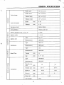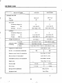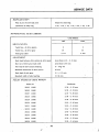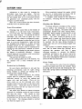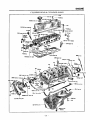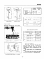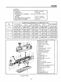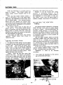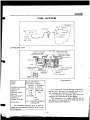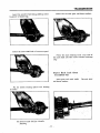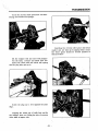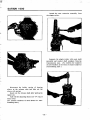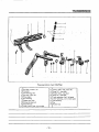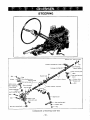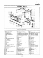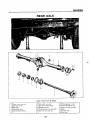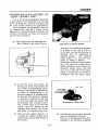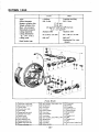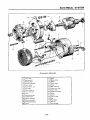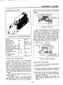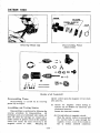
1
l
0
p1ffj
i
1
l
i
t
V
10
Ji f t f
jrtcJcr Ii
I
t
t
If
it1fi 1 1p
1
H kt 1
u
1I
1
L
a
Ep
p
7
l
1
MODI
r tq
v
t
t
t
i
J
1
VV
I
J
J
e
r
fiE
P
j
f Af
f7
f
y
0
in
V
c
Y
j
o
6
C
J
l
f
o
ro
rJa
0
e
c
r
7
@ J
@
m
U
@l
@loa
1o
1J
Jf
J
n
l
o
If
2
NISSAN
MOTOR
CO
6 171 G1NZA CHUOKU
TOKYO
CABLE ADDRESS
PHONES
JAPAN
NISMD
TOKYO
5431 5523
L TD
i
j
i
5
t
JW
f
i
a
1l
t
1if
I
3
manual
This
h
1
o
i
J
W
lti
has
been
1
complies for purpose
i
assisting
DATSUN 1000 distributors and dealers for effective service and
maintenance
major
of the Model B10 Series
components
comprehensive
assembling
It
is
is
described
instructions are
in
Each
assembly
detail
In
given for complete dismantling
emphasised
that
only
genuine
DATSUN
MODEL
VB10
1000
Spare
replacements
DATSUN
1000
addition
and inspection of these assemblies
Parts should be used as
DATSUN
of the
1000
MODEL
Bl0
e
t l
ir
Jl
fi
CONTENTS
Page
I
GENERAL SPECIFICATIONS
IX
SERVICE DATA
1
ENGINE
Cooling System
3
Lubrication
9
SERVICE OPERATIONS WITH ENGINE IN POSITION
Rocker Mechanism
REMOVING
17
18
REFITTING
27
Operation with the Engine Removed
28
IGNITION TIMING
47
Distributor
47
Adjusting the Ignition Timing
48
Troubles
50
Remedies
FUEL SYSTEM
53
Carburetor
53
The Gasoline Tank
57
Adjustment and Inspection of Engine
62
CLUTCH
67
TRANSMISSION
73
CHASSIS
95
STEERING
steering
95
Gear
Housing
99
FRONT AXLE
Dismantling the
Front Spring
103
Front Hub
105
106
Upper Link
108
Lower Link
108
REAR AXLE
Inspection
Repairing of Disassembled
Assembling Adjustment
109
Parts
115
116
BRAKE SYSTEM
125
PROPELLER SHAFT
131
REAR SUSPENSION
133
r
DATSUN
1000
ELECTRICAL SYSTEM
Alternator
Generator
Handling
Shooting List
140
140
14 Items on
149
Trouble
150
Starter Motor
BODY
137
151
159
DATSUN 1000
GENERAL VIEWS OF BID
1
180
1
I
i
1
l
o
II
i
l
1
LL
f
n
1
1
I
i
1
1
I
I
0
in
1
I
i
Ii
I
1
385
II
c
I
I
b
1
190
llf
O
Full width
1
280
t62S
s
445
Full length
Full
without the
ider
3
800
dude the
ider
3
820
length
GENERAL VIEWS OF VBID
r
i
Ai
0
t
i
Of
j
n
n
180
1
in
I
0
0
N
0
1
LN
L
1
1
I
I
8
I
I
I
n
1
h
1
2
Full
These
specifications
are
subject
to
280
length
3
800
change without
notice
28 5
DATSUN
1000
o
GENERAL SPECIFICATIONS
B10
ITEM
VB10
S T D
Deluxe
3 800 mm
Overall length
149
3
6 in
1
Overall width
820 mm
150
4 in
S T D
3
Deluxe
800 mm
149
445 mm
1
345
1
2
1
mm
280
89
1
LL
8 in
93 7 in
1
1
255 mm
100
1
1
1
Rear
1
1
mm
160
road clea
6
O H
to the F E
w
o
22
O H
to the R
E
w
o
3
625
Vehicle weight
Max
Max
6
23 0 in
850
4 in
kg
7 in
585 mm
8 in
3
645
kg
1422 lb
1378 lb
mm
170 mm
mm
3 in
875 mm
B
180
46 6 in
580 mm
B
190 mm
46 9 in
46 6 in
Min
mm
32 7 in
190 mm
180
160
830 mm
mm
46 9 in
Tread
mm
45 7 in
43 3 in
Front
285
50 6 in
48 2 in
LH
385 mm
2 280 mm
mm
630 mm
1
LW
mm
54 5 in
64 2 in
Room space
445
4 in
56 9 in
53 0 in
Wheel base
820 mm
150
56 9 in
Overall height
3
6 in
645
mm
3 in
kg
665
1422 lb
kg
1466 lb
Right
49
49
Left
49
49
LA
speed
135 km
135 km
100 MPH
100
MPH
130 km
130 km
97 MPH
97 MPH
I
d
r
DATSUN 1000
Grade ability sin
I
o 387
8
o
379
o
turning
radius
13
131ft
Model
A10
Manufacturer
NISSAN MOTOR CO
Classification
Gasoline
Cooling system
Water cooled
No
of cylinder
0
40
40m
Min
I
306
m
1 ft
LTD
4 in line
arrangement
Cycle
4
Combustion cbamber
Wedge
Valve arrangment
o H V
Bore x Stroke
mm
73 x 59
Displacement
l
o
988
8
5
2
87 x 2
32 in
60 3 cu in
1
Z
Compression
ratio
Compression
pressure
0
Z
kg
cm
r
p
m
r
p
12 0
350
48 4
000
975
3 600
1
01
t
Max
exploding
Max
mean
Max
power HP
Max
torque SAE
Length
x
pressure
kg
cm
effective pressure kg
Width
r
x
kg
Height
Weight
r
p
m
62 6 000
SAE
p m
m
cm
m
r
p
8 5 4 000
m
mm
547 x 553 x 590
kg
91 5
Position
Front
Type of piston
T Slot
Material of piston
LoEX
No
of
Piston
ring
61 5 ft lb 4000 r p
Pressure
2
Oil
1
II
m
301
1
GENERAL SPECIFICATIONS
C
Intake open
12
B T D
Intake close
48
A B D C
Exhaust open
50
B T D
C
Z
Exhaust close
10
A T D
C
C
Z
Intake
mm
0
35
Exhaust
mm
0
35
Valve timing
Valve Clearance
Starting method
Starter Motor
Firing Method
Battery coil type
Ignition timing
E
Ignition order
Z
0
Ignition coil
B
T D
C
r
p m
8
600
1
3 4 2
Type
C14
51
Manufacturer
HITACHI
Type
D412
Manufacturer
HITACHI
Type
L45
Manufacturer
HITACHI
E
1
Z
C
Distributor
Z
0
E
Spark Plug
Z
C
Thread
mm
14
Cap
mm
o 7
0
1
8
Type
DCG286
Manufacturer
HITACHI
Throttle vlve
E
53
3
26
28
bore
mm
Venturi size
mm
20 x 7
Main jet
mm
o 95
1
Slow jet
mm
o
0
Power
mm
24 x 7
Carburetor
p
Air
jet
o
Down
Draught
1II
80
60
40
oA TSUN
1
l
r
1000
Type
Paper element
Manufacturer
T8UCHIYA
Type
Diaphragm
Manufacturer
8HOWASEIKI
Fuel Tank
35 for B10
Air cleaner
f
ell
ell
l
l
r
Fuel pump
Capacity
30
Lubrication method
Forced fuH flow
Oil pump type
Trochoid type
Oil filter
Paper filter
Oil pan
2
for VB10
Lubricating system
Cooling system
Generator
arter
5
Type
Pressure feed water cooled
Radiator
Corugated fin
Capacity of cooling
water
Type of
Battery
capacity
water pump
4 5
Centrifngal type
Thermostat
Pellet type
Type
N40L
Voltage
V
Capacity
A
12
H
40
Type
LT125
Manufacturer
lllTAClll
Generating
method
0J
Alternator
Voltage
V
12
Capacity
W
250
Voltage regulator
TL1Z 10A
Type
8114 87
Manufacturer
lllTAClll
Voltage
12V 1
power V HP
IV
tube type
0
J
GENERAL SPECIFICATIONS
Type
Single dry disc
u
E
Number of place
1
1
U
Out
riI
dia
In
dia
Total friction
area
x
x
Thickness
Facing
2
mm
160 x 110 x 3
cm2
212
2
U
riI
0
4 Forward 1 re
all synchro
mesh on forward
verse
gears
gears
Remote control
Floor shift
verse
Type
Z
0
Z
0
3 Forward 1 re
Operating method
mesh
all synchro
on
1st
3
38
3
76
2nd
173
2
17
3rd
1 00
1 40
Z
p
Z
E
p
E
Gear ratio
4th
1 00
Reverse
Propeller shaft
Length
x
3 64
Out dia Xln dia
mm
Type of universal joint
3 64
1 178 x 63 5 x 60
3
Spicer
Type of gear
Hypoid
Gear ratio
4 111
Housing type
Banjo type
Final gear
BI0
4 375
VBI0
Differential gear
Type
0
Z
p
number of gear
Straight bevel pinion
Type of gear
Recirculating
Gear ratio
15
2 each
ball type
1
riI
riI
E
riI
U
riI
0
Steering angle
Inner
45
Outer
36 36
Steering wheel diameter
Wheel arrangement
mm
400
Front
2 wheels
Rear
2 wheels
0
Z
Z
Z
Front axle
Wishbone ball joint type
p
Toe in unloaded
2
v
3 mm
forward
r
r
DATSUN 1000
l
0
w
0
0
Z
Camber unloaded
unloaded
C1ster
1
45
2
15
6030
Inclination angle of king pin
Z
Z
p
Type of
rear
Semi
axle
floating type
Rear
2 leading
leading and trailing
Front
Type
dimension
front
mm
35 x 4
8 x 195
Lining dimension
rear
mm
35 x 4
8 x 195
Lining
p
g
p
w
E
Cll
Cll
E
Total braking
area
front
cm2
273
Total braking
area
rear
cm2
273
mm
203 2
mm
17 46
mm
20 64
mm
20 64
kg cm2
175
Cll
g
w
Inner dia
of drum front
l
Inner dia
of master cylinder
p
Inner dia
of wheel
Inner dia
of wheel cylinder
p
rear
cylinder front
rear
0
Max
Mechanical for
Type
w
ii1
p
oil pressure
Lining
0
Z
dimension
Total braking
area
mm
35 x 4
cm2
273
mm
203
ear
wheels
8 x 195
e
Inner dia
of drum
2
Po
Transverse leaf
Front
Spring
size
Out dia
x
Length
mm
Semi
Rear
Z
0
Cll
Z
976 x 50 x 4
Spring
Length
Width
x
Thickness
No
mm
1
7
2
50 x 7
2
1
x
BI0
150 x
size
x
6
elliptic leaf spring
50
1
spring
150 x
50
x
5
50
x
11
VB10
1
Po
Cll
Helper spring
mm
Shock absorber
Front
Telescopic type double
action
Shock absorber
Rear
Telescopic type double
action
VI
DATSUN 1000
MODEL BID ENGINE
PERFORMANCE CURVE
60
50
40
r
8
E
V
e
30
7
is
o
0
6
0
E
a
20
5
to
o
300
100
1
i
E
o
U
8
12
16
24
28
32
Engine Speed
VII
36
rpm
40
44
48
52
56
60
x
102
oo o
2
o io4
E
8
0
1
11
0
0
OOIl
l
000
c
1
2
60
4
150
m
140
p
p
g
ill 380
i
000
H
7
130
OOO
3
6
920
1
1
oOO
3
s
oI
S6PS
17
raO
f
m
110
100
So
RUNIG
ratio latio tatlo
Ie
al0
Find
ltlO
drl
IbiHty
H
3tdl Mu
znd
Jj
f
Car
SO
0
MODEL
Spe d
0
MIX
MIL
troth
70
P
l
tOfClU
Stade
lpe d spe d
b
80
0
51
0
I
to
0
ICO
00
soo
400
il
o
0
JlQ
000
r
ceu
1J
Q
1
3
4
m
1
140
p
600
I
3
375 380 134 ooo 115
t
1
m
W
r
000
6
1
3
4
160
150
I
561
7
120
y
if
5
g
l
110
J
t
I
7
100
90
RUNIG
YBIO
MODEL
h
If
0
abiUty
O
j
gt
final
il pe edrl t peed
1d
Zl
rd
de
l
I
ue
torq
D
MOl rM
Spe d
70
RO
H
i
60
C
I
SO
Ma
0
0
I
0
I
I
10
0
I
oo
500
400
t
gj
0
CO
SERVICE DATA
Tightening torque
Tightening torque kg
ENGINE
Cylinder head bolt
4 5
4
8
Main
bearing
5
0
5
3
Con
rod
3 4
3
6
Fly wheel bolt
2
5
3
0
Camshaft sprocket
4 0
4
5
Rocker shaft bolt
2
2
3
Water pump nut
12
13
Oil pump bolt
13
15
Oil pan
05
06
Front cover
05
06
Front cover
10
14
Rear extension
1
6
2
2
Hub nut Without lubrication
2
3
2
5
Hub nut
Coating
16
Hub nut
Begining
cap bolt
bearing
cap bolt
0
TRANSMISSION
FRONT SUSPENSION
with grease
to turn motion
Under 9
18
kg
cm
Front shock absorber bolt
2
2
2
8
Tension rod
4
0
4
5
4 2
5
3
4
0
4 5
Upper ball joint
3
5
4
9
Upper ball fixing bolt
1
6
2
2
Lower ball
55
76
2
0
2
4
2
5 3
4 2
5 3
Tension rod
Suspension
Front side
Rear side
member
fixing
bolt
joint
LQwer ball joint fixing bolt
8
r
Upper
link
Lower link
spindle fixing
bolt
pin
IX
m
DATSUN 1000
REAR SUSPENSION
fixing bolt
1
5
2 0
Rear shock absorber
2
0
2
5
U bolt
3
5
4
0
Rear shaft
Rear
spring front pin
3 5
4
0
Rear
spring shacle pin
2
0
2
5
GEAR CARRIER
20
Gear carrier
15
Pinion nut
14
Drive gear
3
0
3
5
Side bearing cap
4 2
4
9
2
5
16 8
STEERING
Gear box
6
fixing bolt
Gear box side
1
cover
18
Gear rear cover
25
14 0
Gear arm nut
Gear
arm cross
Idler
arm
rod
bracket
Tie rod end
Steering wheel
8
0
nut
3
5
4
9
1
9
2
6
35
49
4
4 5
0
ENGINE
SERVICE
DATA
3 04 L
Oil content
include oil filter 0 54L
distinct
Min 0 6 L
between level gauge mark Max
Cooling
3 8
water
1
L
8 L
Transmission
0 8 L
Idling
600
r
p
m
r
with heater 4 5 L
Radiator side
p m
Fan belt slack
13 15 rum
Compression
More than 10
x
2 L
Engine side
kg cm2
350 r p m
SERVICE DATA
Spark plug
Point gap
07
gap
o
distributor
08mm
45
0
55
600 r p
mm
Ignition timing
8
Vacuum
More than 400
m
mmHg
600
r
p m
CYLINDER HEAD
Limit strain
Under 0 10
Thickness of gasket
Free 1
Allowable difference of each cyl
An eliptic 0 015 Taper within 0 020
mm
10 Used 1
05
inner dia
bore
Wear limit of inner dia
02
Clearance between piston and
o
mm
PISTON
03
0
at 200
04
C
bore
cyl
Fixing
F mark to front side Con
direction
rod oil
hole to
camshaft side
Piston oversize
S T D
Measure with feeler gauge between
Pullout measuring 0 5 1 5 kg with 0 03
piston
cyl
bore
0 25
0
50
0 75
1 00
1 25
1 50
mm
thickness feeler
Clearance between piston groove
Within 0 20
mm
ring
Piston ring end gap
Within 1 0
Piston ring
S
over
size
Method of inserting piston and pin
T D
0
mm
25
0
50
0
75
Press fit to piston and con
1
1
1 00
1 25
150
rod small end
5t
CONNECTING ROD
Within 5 gram for each weight diff
Allowable difference of gross
weight
with
Alignment
connecting
on a con
rod
piston
o
rod
05
mm
Allowable limit with pin
on
100 mm
length
Material of big end bushing
Connecting rod
side
F 500
Within 0 4
clearance
Clearance big end bearing
Con
rod side clearance
Connecting bushing
thrust
under size
o
01
0
05
o
20
0
30 limit 0 40
S T D
Xl
mm
0
008
0
12
0 25
C
0
50
0
75
1
00
r
DATSUN 1000
CRANK SHAFT
0 03 mm
Wear limit at pin portion of
elliptic
or
taper
crank shaft journal
Limit crank shaft
Not to exceed 0
alignment
Side clearance of crank shaft
Within 0 3
Crank shaft journal oil clearance
0 02
Portion of crank shaft thrust
2nd
Bushing over
journal
bushing
size of crank shaft
0
05 mm
mm
06 mm
side
S T D
0
25
0 50
Dimension of crank shaft
jorunal
49 951
49 964 mm
Dimension of crank shaft
pin
44 961
44 974 mm
0
75
1 00
CAM SHAFT
Wear limit of eam shaft
Limit of
alignment
Height of
of
jornal
o
shaft
cam
36 45
Wear limit of cam
Clearance
bushing
Bushing under
o
cam
36 55
at all
5
01
0
shaft
cam
or
taper
05 mm
cam
End play of
elliptic
03 mm
shaft
o
size
03
Inlet
Exhaust
height
2mm
0
S T D
07 mm
0
25
same
0 50
0
journal for all
75
VALVE
45 30
Angle of valve face
Exhaust
1 3 mm
Inlet
Exhaust
Limit valve head thickness
o
5
Inlet
mm
lxhaust
Dia
8
0 mm
Diameter
valve stem
Inlet
of stem
Wear limit
valve stem
Clearance to guide
Tappet clearance
Clearance valve guide and
guide
o
35 mm
Inlet
o
02
04 mm
0
inserting hole
Clearance for valve seat inserting
006
Limit of valve seat depresion
o 2mm
Valve seat
S T D
0
S TD
050
over
Valve guide
size
over
Valve spring
size
Free
45 7
III
009mm
mm
50
Less than 0
Exhaust
at hot
10 mm
7
SERVICE DATA
Limit valve
Fix load
spring
Free
length
44 7
fixed length
Clearance valve lifter
Clearance valve locker
mm
No 1 30 0
Within 0 15
guide
arm
38 5 No
shaft
o 02
0
2
61 2 31 0
mm
05
mm
FL Y WHEEL
Limit shake on the frictional face
02 mm
Nos
105
of teeth
ring
gear
THERMOSTAT
to operate
Temp
Max
82 C
of valve lift
More than 9
mm
at 95 C
WATER PUMP
fi
Rotation ratio water pump
pulley
1
05 for crank
l
85
Current quantity
pulley
400 r p m
OIL PUMP
r
Oil pump
Trocoid gear
Oil pressure
3
5
Thickness of adjusting shims
o
5mm
4 0
type
kg cm2
for oil regulator
Quantity of oil pumping
L
nnn
r
19 5 3000
p m
FUEL PUMP
Perlormance
750cc
3000 min r p m
1
xm
t
r
DA TSUN 1000
A
MANUFACTURER
MITSUBISHI
HITACHI
STARTER MOTOR
f
SS114
Type
MW
87
V1R
30
30tl
12
11
Less than 60
Less than 60
Constant
NO LOAD
Terminal voltage V
A
Ampere
Rotation
r
p
More than 7
m
More than 4
000
800
LOADED
Terminal voltage
V
Ampere
A
Torque
Voltage
for
kg
pinion
6
6
Less than 470
Less than 420
More than 0
m
More than 0 68
9
Less than 9
Less than 8
out
Front
Clearance shaft
3
Medium
Less than 0
2
mm
Less than 0
2 mm
Less than 0
2
Less than 0 45 mm
bushing
Rear
Alignment of shaft
Out dia
Less than 0
03 0
2 mm
Less than 0 05 mm
More than 0
Depth mica
height
Wear limit
tension
2 0 mm
Less than 0
Amendable accuracy of commutator
Spring
32
Less than
out limit of commutator
Brush
1 mm
33
standard
Diameter wear limit of commutator
Run
mm
Less than 0
Limit
of commutator
1
9
2mm
16mm
15 mm
5 mm
7 mm
800 g
Standard
Weakness limit
Up
XlV
1
to
15
700
g
mm
SERVICE DATA
NGK
HITACHI
MANUFACTURER
ALTERNATOR
Alternator
LT125
B
02
U sed rotation
1
5
Constant revolution
14
h revolution
Voltage
Out dia of
Wear limit
31
Dia
Rotor coil
Rotor shaft
Brush
run
height
Less than 1
050
33
mm
0
5
4
07 n
0
mm
mm
mm
7 n
13
mm
7 mm
mm
300
spring
100
mm
19 mm
7
6
6
Under 0 10
St
of brush
000
2 500
out
Wear limit of brush
Strength
12
000
Less than 1
spring
050
6E
380 g
300
400 g
REGULATOR
No load
RL2220B5
TLIZI0A
Type
14 0
regulated
O
5V
GAP
Voltage regulator
Pilot
lamp realy
Air
o
8
1
2
12
Back
0
8
1
1
0
Point
0
3
0
4
Air
0
9
1
2
Yoke
o 9
1
Core
08
Point
o 4
Yoke
0
5
o 2
Core
0
5
0
6
Back
0
8
1 1
Point
o
4
0
5
Point
0
8
11
i
tt
l
t
J
I
t
h
xv
t
1
DATSUN 1000
lllTAClll
MANUFACTURER
MITSUBlSlll
DISTRIBUTOR
D412 53
Type
TVA
8
Ignition timing
Point contact
49
angle
Point gap
Contact arm
600 r p
tension
m
55
0 45
spring
4FIL
0
500
55 mm
10
650 g
fifS
ADVANCE CHARACTERISTIC
Governor
type
Commerce 450 r p
Max
12
1
300
r
p
o
m
6
m
11
Vacuum
type
Commerce
150
mmHg
Max
305
mmHg
9
5
18
7
9
0
0
17
5
5
at 1
at
8 7
10 5
at
C14
l
HP5 1
51
160
mmHg
at 250
350
mmHg
More than 6 mm
Secondary voltage
3 ways spark gap
Primary coil
resistance
Secondary coil
resistance
E
12V
Primary voltage
3 2
Below 20
XVI
000 n
4
In
Below 17
m
440 r p m
IGNITION COIL
Type
m
at 1 028 r p
13 0
5
8
7
at 500 r p
000 n
SERVICE DATA
MANUFACTURER
HITACHI
NGK
L45
NGK B 6E
SPARK PLUG
Type
Screw x Reach x
Hexagonal Length
14 x 19 x 20 6 mm
7
Gap
o
7
0
31 lfrK
8
iil
m
BATTERY
Type
NS40L
C20
Capacity
S ecific
h
32A H
gravity
Discharge
Voltage
hour
150 C 150A
5 second
1
260
2
5L
More than 2
150 C 150A
5 minute
More than B 4 V
CLUTCH
i
Setting height of diaphragm spring
31 5 mm
Wear limit of cJutch
o
Disc
facing
run
facing
out
5 mm
Less than 0
Play of with drawal lever
Height
of clutch
by the head of
5
rivet
r
mm
15
2 0
pedal
144
Play of clutch pedal
15
5 mm
20 mm
TRANSMISSION
Type
Synchromeshed
Reverse one
on
2nd
3rd gear
stage
Gear ratio
1st 3 380
Gear type
Helical gear type
XVI
the 1st
2nd 1 734
3rd 1 000 Rev
3 640
r
DATSUN 1000
driven gear
Main drive gear
Back lash of each meshing gear
second gears
first gear
Gear ratio of
MAIN
speed
4
meter
00
16 4
DRIVE GEAR
19
Main drive gear Nos
MAIN SHAFT
Second gear teeth Nos
25
First gear teeth Nos
31
Reverse gear teeth Nos
31
Reverse gear thrust clearance
0
15
0
25mm
First gear thrust clearance
0
15
0
25mm
Second gear thrust clearance
0
1
0
3rnm
Front gear thrust clearance
0
1
0
35
0
8
1
45 rnm
0
5
Clearance between boulk ring
Cover
adjusting
each gear
shim
0
2
1 mm
Ball bearing Rear
Front
Bearing type of spline
0
Bushing
COUNTER GEAR SHAFT
Driven
29
gear teeth Nos
Counter gear teeth Nos
22
First gear teeth Nos
14
Reverse teeth gear
13
Clearance of front thrust
0
02
Thrust washer size
0
8
Bearing type of spline
Front
0
Q
08 mm
9
10
rear
1
17
Clearance between shaft
bushing
0
032
Clearance between gear
adapter plate
0
1
0
5
0
1
0
4
Clearance to snap ring
0
077
FORK SHIFT
Length
of
16 4
locking ball spring
xvm
rum
1 2
balt bearing
REVERSE IDLER
Gear teeth Nos
1
at 7 kg
1 3 mm
SERVICE DATA
PROPELLER SHAFT
Play
at
pin of universal joint
Adjust by
1
Thickness of snap ring
58
1
ring
snap
56
1
54
1
52
1
50
1 48
1 46
DIFFERENTIAL GEAR CARRIER
CAR MODEL
Bl0
V010
9
8
37
35
SPECIFICATION
Teeth Nos
of drive pinion
Teeth Nos
of drive gear
4111
Final gear ratio
4
375
ADJUSTMENT
Back lash between drive pinion
drive gear
Less than 0
10
08
Run
out of drive gear back side
Less than 0
Pre
load of drive pinion bearing
6
8
kg
Standard dimension of drive pinion
45mm
Back lash of side gear
o
Standard width of side bearing
17
1
0
0
15 mm
mm
cm
2mm
50 mm
ADJUST WASHER OF DRIVE PINION
Thickness
Parts No
38125
18000
2
30
2
32 mm
38126
18000
2
32
2
34 mm
38127
18000
2
34
2
36mm
38128
18000
2
36
2
38mm
38129
18000
2
38
2 40 mm
38130
18000
2
40
2 42 mm
38131
18000
2
42
2 44 mm
38132
18000
2
44
2 46 mm
38133
18000
2 46
2 48 mm
38134
18000
2 48
2
50 mm
38135
18000
2 50
2
52 mm
38136
18000
2 52
2
54 mm
XIX
J
r
DA TSUN 1000
38137
18000
2 54
2
56 mm
38138
18000
2 56
2
58 mm
38139
18000
2
2 60
58
mm
ADJUSTING SHIM OF DRIVE PINION
Parts No
Thickness
38153
18000
050mm
38154
18000
0
075 mm
38155
18000
0
125 mm
38156
18000
0 250 mm
38157
18000
0
SPACER OF DRIVE
500
mm
PINION
Parts No
Thickness
38165
18000
5 75 mm
38166
18000
6 OOmm
38167
18000
6
25
mm
THRUST WASHER OF SI DE GEAR
Parts No
Thickness
38424
18000
0
76
0 81
38424
18001
0
81
0
86 mm
38424
18002
0
86
0
91 mm
mm
ADJUSTING SHIM OF SIDE BEARING
Parts No
Thickness
38453
18000
0
050 mm
38454
18000
0
075 mm
38455
18000
0
125 mm
38456
18000
0
250 mm
38457
18000
0
500
mm
SUSPENSION
FRONT SPRING
Dimension
L x W x T
Nos
976
Free chamber
Spring
x
120
constant
2 05
xx
50 x 4
mm
kgmm
6
SERVICE DATA
FRONT SHOCK ABSORBER
Stroke
130
Absorbability
0
3
sec
extensile side
Contractile side
mm
58
kg
20
kg
REAR SPRING
B10
VB10
50 x
Length
x
width
x
thickness
Nos
1150 x 50 x 7
Free chamber
Spring
2
156 mm
constant
1 45
Span
kg
7 x 2
150 x 50 x
5
1
50X11
1
161
3 95
mm
1150 mm
5 mm
kg
mm
115mm
REAR SHOCK ABSORBER
Stroke
160
Absorbability
0
3
sec
extensile side
Contractile side
160 mm
mm
70
kg
25
kg
105
kg
35
kg
STEERING
SPECIFICATION
Steering
gear
Steering
gear ratio
Max
type
Recirculating ball type
15
turning angle of front wheels
3 4
Inside
45
Outside
Steering
1
36
gear oil
36
MP
90 O
24L
Steering wheel dia
400 mm
Play of steering wheel
At the top of around of wheelless than
20
25 mm
WORM BEARING ADJUSTING SHIMS
Parts No
Thickness
48031
18000
0
05 mm
48032
18000
0
07 rum
48033
18000
0
08 mm
48034
18000
0
10
XXI
mm
DA TSUN 1000
48035
18000
o
20 mm
SECTOR SHAFT ADJUSTING SHIMS
Thickness
Parts No
48131
18000
1
52
1
53 mm
48132
18000
1 55
1
56 mm
48133
18000
1
58
1
59
48134
18000
1
61
1
62 mm
48135
18000
1
64
1
65 mm
mm
CLEARANCE
Clearance of ball nut to direction of shaft
Less than 0 02 mm
Clearance between of shaft T groove
Less than 0 1 mID
shim
Clearance of sector shaft
Less than 0
bnshing
12 mm
FRONT WHEEL ALIGNMENT
SPECIFICATION
Toe
2
in
3mm
Camber
1
45
Caster
2
15
King pin angle
6
30
Side slip
Less than 3 mm with each
lmm
Turning angle
45
Inside
36036
Outside
kg
Rotation torque front hub Motive
Less than 9
Clearance of front hub to direction along
Less than 0 08 mm
cm
the shaft
Clearance of ball joint to direction along
Less than 0 9 mm
the shaft
XXII
running distance
SERVICE DATA
BRAKE
F
FRONT
R
REAR
ITEM
FOOT BRAKE
Type
Two
Drum inner dia
203
2
Leading trailing
mm
Leading trailing
Less than 1 mm
Leading trailing
elliptic
Within 0 02
mm
Leading trailing
cylindericallimit
Within 0 02
mm
Leading trailing
Drum over size
Drum inner dia
Drum
leading
at 35
mm
from
Drum surface
cylinder
roughness
Honing by
paper less than 1
Leading trailing
6
RETURN SPRING
Wire dia
x
x
Free
length
3
211
x
118 mm x 20 5 rolls
Cy side
2
011
119
x
2 mm x
28 rolls
Rolls
Adjuster side
x
Fixed load
x
55
Fixed length
kg
x
127
1 mm
2
011
x
69
5 mm
20 rolls
Cy side
Adjuster
10
6
side
kg
8 6
x
132
kg
x
7
76
mm
7
WHEEL CYLINDER
Inner dia
20 64 mm
Clearance between
cylinder
0
02
0
20 64 mm
105 mm
0
02
0 105 mm
piston
Limit of clearance
Piston spring Free
fixed length
x
length
fixing load
o
x
15 mm
0
28 mm x 16 mm XLI
0
1kg
15
mm
28mm x 16mm Xl
10
1kg
LINING
Length
x
width x thickness
Wear limit
Thickness
35
mm
x
195
mm
4
x
8 mm
size
5
3 mm
0
5 3 mm
5 mm
for service use
PE DAl
Height of pedal
144
Remained stroke
More than 25 mm
Play of pedal
10
Adjusting shim for pedal height
16
xxm
5
2 mm
15 mm
mm
8
More than 1 mm
More than 1 mm
over
35 mm x 195 mm X 4
Part No
30611 27260
0
5 mm
mm
DATSUN 1000
o
8 rom
o
5 rom
Part No
part
No
MASTER CYLINDER
Inner dia
17
Remained pressure
03
07
Oil pressure
175
kg cm2
100
kg by foot
Clearance between cylinder
46
002
piston
Limit of clearance
o
XXN
15
mm
0
rom
kg cm2
105 mm
30612 27260
30613 27260
1
NISSAN
MOTOR
CO
I
L TO
l
i
g
C
y
T
1
TG 1l
131
TI
7
1
ENGINE
This engine has three main bearings and
The
use
the
mounted
individually
rocker
arms
seats
A
lubrication for portion of the engine
The main oil
gallery along valve lifter
The
areas
passes oil through drilled passages to each carn
and main bearings through the valve lifters and
hollow
push rods to the rocker
are
the
and
carry
skirt type
split
two
of
compression
rings and a oil control ring
The piston pin is pressed in small end of
connecting rods which have steel backed lead
and copper alloy changeable big end bearings
which
trocoid gear type oil
pivot
driven
camshaft
pump
by
provides full pressure
ball
on
pistons
alloy
aluminum
the valve lifters and hollow push rods to operate
counter
The end throst
balanced
on
crankshaft is fitted
this component is taken by the
second main
The
arms
are
bearing with flange
centrifugal water pump
and
cooling fan
ddven by the generator belt
GENERAL SPECIFICATIONS
4
Design
cylinder
Bore x stroke
Displacement
Compression
Max
B
73
in line 4
59
mm
cycle
87 x 2
2
988
cc
61
ratio
H P
torque
Ignition timing
ax
x
O H
32iJ
cu
8
SAE
62 HP at 6
61 5 Jt
Sff
lb
at 4 000 r p
8
m
8
C
in
5
1
000 r p m
Kgiat
fi g
oO
i
5m
B T D
V
r
p
i
m
at 600 r p m
1
1l
g
J
1
DATSUN
1000
2
to
ENGINE
COOLING SYSTEM
Cylinder head
Thermostat
I
Water pump
Manifold
aG
B
oal
Cylinder
Fan
Cooling System
An
efficient
imporatnce
of the engine
pay
particular
cooling
ensure
to
and it
is
is
system
controls
of major
the satisfactory running
therefore
per
necessary to
is
maintained by water
combined with
an
Fill to
efficient fan
valve
system
is
incorporated
within
filler plug well
cooled radiator and thermostat
The
at
approximately
0
4
kg
Do not remove the filler cap if the
water
cooling system
pump circulation
pressure
temperature of the coolant is above boiling point
or if the engine is running
Topping up should
only be required occasionally to replace water
lost through the overflow pipe
Top up when
the engine is cold and if possible use clean soft
attention to its maintenance
Description
The
the
sq cm
cold may
pressurised and the relief
flow
cause
1
2 in
Overfilling
water to flow
The
pipe
capacity
approximately 4 5 liters
in the radiator filler cap
3
of the bottom of tl
ie
when the
through
of
the
engine
is
the over
system
is
DA TSUN 1000
21
J
1
1
11
9
6
10
tf
3
o
Radiator
1
Ass y
radiator for cooler
5
BoIt
2
Ass y
cap
pressure valve
6
Nut
7
Washer
8
Waiher Iock
3
4
drain
Handle
Packing drain
cock
cock
plain
4
9
Hose
cylinder
10
Hose
radiator
11
Clamp hose
head
to
to water
radiator
pump
ENGINE
its
from
Thermostat
avoid
In
is
order
to ensure
maximum
essential to keep the
efficiency it
engine operating tem
peratures within certain limit
a
pellet type thermostat
To
is fitted
in the water outlet at front of the
Pellet type thermostat
ciple of rapid
works
up the car
thermostat
is
opening
set
by
the
manufacturer and can not be altered
assist this
During decabonising it is policy to test this
opening by immersing the thermostat in water
raised to requisite temperature
The valve
located
being
laying
The
and the hose reconnected to
housing
cylinder head
by the prin
should
variation of solution of wax
under these
open
fails to open a
but if
conditions
it
unit should be fitted
new
Overheating
may be caused
Overheating
belt
excessive
running
the
with
water to circulate
Fan Belt
A
the
Pellet
which controls
wax
by solution of
slack fan
far
retarded
failure of the
108s of water
or
driven
this also
belt
from
driving
the
carnkshaft by
by first loosening
dynamo in
and moving the dynamo towards tl e
which
hold the
the belt over the fan and onto the
filled
pellet
mash room valve
a
wax
Fan p
ey
When the
engine is cold this valve is closed
and on starting the engine the flow of water to
the radiator is temporarily restricted
Due this
cylinder
rise
the temperature of the water in the
head
and cylinder jackets will quickly
thus ensuring rapid warming up
The
heat
so
Alternator
generated will gradually
press
up the
piston by shrinkage of synthetic rubber
and
so
ultim tely
opening the valve
permitting a full flow of water to the radiator
sleeve
The thermostat itself is detachable
should
be
occasion
arise
it
can
Crank shaft
Standard
Fan Belt Adjustment
21200
61001
Rated Temperature
Open
at 76
Open fully
Optional for cold district
pulley
therefore
be removed
Part No
21200
61001
Open
50C
1
at 900 C
at 820 C
Open fully
5
a
the alternator
be fitted
can
bolts
clamp
position
Slide
engine
fan pulley
Thermostat
consists of metalic
The device
with the
Type
new
a
Adjustment
The fan is
belt
too
ignition
carburetor adjustment
incorrect
V
by
carbon deposit in the cylinders
15
at 95 C
5
C
1
50C
C
1
5
C
DATSUN 1000
by bringing the
The belt
alternator away
engine
be
to
should
sufficiently tight
prevent slip yet
is
Adjustment
then
be
the
belt should have 10 to 15
the
mm
generator and crankshaft pulley when
midspan is pushed firmly
run
for
timed minute to
a
water has been cleaned from the
A
slack between
the
should
When completely drained the engine
made
from
the
the
suitable notice
that all
system
should be then affixed to
that the water has been
indicating
radiator
ensure
drained
After the correct tension has been obtained
securely lock
position again
it in
Flushing
the Radiator
To ensure efficient circulation of the coolant
Frost Precautions
Freezing
the
in the
or
Ice in the hose
and may
but
with the muff
lower hose
will
A
care
fully closed
When frost is expected
used in
winter
boiling
of the solution is
make
sure
in fact
that
mixture
the
into
and
in anti freeze in the
it
taking
out
in the
should be allowed to
run
comes out clear from the drain
a
into the
are
in cases
the
efficeient
stiff piece of wire should
taps during draining to
becoming clogged with
not
turn the
where the
operator
practice
completely and flush
flow
clear
but
excessive
to
will
up is
it
more
find
remove
in the
radiator
serve
furring
the radiator
reverse way to the
upside down and let the
water flow in through the bottom hose connection
is cold
a
scale
This method of radiator flushing may
well
with the container
system
cooling system has
it
of
the
sediment
must be made up in accordance with instructions
up when the
when
water
that they
ensure
sary
topping up with water reduces
the degree of protection
afforded
Solution
If the
until
be inserted
up to the
Excessive
Top
again
The
At intervals
taps
strength
The
strength advised by the manufacturers
the
must
be
maintained
of
solution
by
strength
anti
neces
with
freeze
solution
as
topping up
supplied
and
spring
through
will result
when the car is to be
low temperature
a very
the
preferably before putting
muff can be used to
or
or
formation
system should be
with clear running water
periodically flushed
circulation
be taken not to run
must
the
reduce
to
sediment in the radiator
connections
water
stop
boiling
cause
advantage
first at the bottom of
occur
may
radiator
and
to be drained
container
and out of the top connection
run
and
use
Water
again
Pump
After draining the water from the radiator
Draining
Protection by
remove
cars where anti freeze is
On
not used
must
be taken druing
following precautions
frosty weather to obviate any damage due to
freezing of the cooling system
When heavy frost is imminent the cooling
sufficient
engine
drain
to
merely
with
one
the
and masks
rugs
cocks
cover
the
on
alternator
It is not
be completely drained
must
system
radiator and
There are two
left hand
side
of the
cylinder block and the other at the base of the
radiator
block
Both taps must
drain the
and the
system
ground while draining
be opened to
car must
be
on
level
The drain taps should be tested at frequent
intervals by inserting
that
they
are
clear
a
piece of
This
wire to ensure
should
be
done
the
so that any
taps are opened
obstruction freed by the wire may be flushed out
immediately
by
the water
out when the
The
engine
draining should
the pump unit from the cylinder block
by taking off the fan belt and releasing the set
bolts with spring washers and hinge bolts to the
the
be carried
is hot
6
ENGINE
15
3
7
5
CD
Seal
@
Valve
body
@ Shaft
@ Seal
Portion
embly
CW
contact
surface
Sectiollal
Components of
1
Vane
water
2
Ass y seal
3
Ass y
seat
4
Bearing
5
Wire
6
Hub
7
Cask
watcr
lock
9
pump
water
pUmp
pump
11
Blade fan front
12
Blade fan rear
l3 Bolt
bearing
watcr
Washer lock
to Pulley f m
l4 Washer lock
pulley
t
Water Pump
pump
15
cover
8 Nut
7
Be It fan
ate
pump
View
of
Seal
DATSUN 1000
Adjusting Clearance
and Body
Removing the Pump Shaft Assembly
pulley and cover
and ball bearings are combined
the fan blades
Disconnect
The
shaft
First
First
pulley hub
o
a
out
locked the
Next
5
out
the
pin from
set
assembly
shaft
to
the
mm
bench
on
type bench
Take
the shaft fitting with
between the
vane
end
good condition
the pump body
Water pump hub
a
C
the Bench
A
for Pump Body
Adj
The shaft
and ball bearing assembly
drew out from the
take
with
correctly for
a groove
of
Water
Pump
A
74
0 mm
B
19
5 mm
05 mm
floating seal and
pump body
but
a
reversal
a care
should
that the shaft assembly is
a
ment
B
vane
of the disassembly procedure
ensure
us
C
the
The reassembling of the pump is
fitted
be
body
out
seal which remained the
be taken to
can
slit
a
hole of set ring
of shaft so as to insert and set the
said ring correctly
8
0 4
Take out the thickness gauge and find
body upside down and press
assembly from the vane side on the
Example of
a
the U block
slit wbich
type bench
Thus
on
turn the
out the shaft
U
be nch
and draw out the pulley hub
drift hard bar
the U
the
knock the shaft end with
or
press
On
down
insert the set pin
groove line to
thickness
Inserting
gauge Thickness
with one unit
Put the
press
the Vane End
Hub
21054
18000
Bearing shaft
21035
13201
Seal
y
21026
73000
Seat ass y
21027
73000
ass
ENGINE
LUBRICA TION
To oil p m through
push rod holes
Oil
capacity 3 04
0
t foroil filter
54
Oil Passages
From the relief valve the oil passes into the
the
oil
on the right hand side of
Circulation of Oil
Pressure
unit and is
oil pump
lubrication is
provided by
an
used throughout the
hand side of the cylinder block
from the camshaft gear
The flow then passes via connecting
engine
oilways
draining
into the right
ecentric non
The oil pump is bolted
gallery
main
big end and camshaft
bearings throUgh drillings in the crankshaft
The connecting ends are drilling in the cylinder
and is driven
by the drive gear
block
oil is drawn into the pump via the filter
and is delivered through oil regulator which is
The
the oil
from
the
and
lubricate
situated at the lower body of oil pump
the
to
main
rear
the rockers
pan via the
center
the
rocker
shaft
bracket
to
and then drains back into
push rod apertures
camshaft bearing
The oil
enters
a
gallery on the left hand side of the engine and
individual
the
lubricates
tappets through
drillings
As
in the front
the camshaft rotates
journal register
two grooves
with a small hole in
the camshaft thrust plate thus allowing
amount
a
small
of oil to pass into the timing case twice
of the camshaft to
case
revolution
during
provide lubrication for the timing
chain
and
gears
From the
drain hole
timing
back to
case
the
the oil returns via
oil
pan
The
a
filter
therefore forms part of the main oil gallery and
as
9
such is filled with oil under pressure
DATSUN 1000
The full of the oil enters the element through
holes in the cartridge
and passes
Check for Low Oil Pressure
through the
Check the level of oil in the engine sump by
element into the annular space round the center
means
pipe
if
This
the oil
is
ad bottom so that
l
only escape through a small hole into
space
can
sealed top
the hollow center
The
must
pipe and from this point back
on
then
and
the
oil
when the
filled with
The oil
pan
new
strainer union on the suction side of the oil
connect and
defective
pump
being
rectify
the fault
The drain
the
oil
pan with
new
oil dis
filter
new
change the oil cartridge
lb sq in
2
road speeds
part of
The
engine
removed
kg cm2 on the gauge at normal
whilst approximately 10 lb
sq in
1
hand
by
a
That
there is
a
The
filtered
cartridge
is
bore
in
oil
c
readily
from
particularly
becomes
correct
to
the
the
of the
caused by its
oil
is
passage
all
crank pin
correct
the
oil
the
sides
the
working
high
or
choke up
of
oil
the
is
if the filtration
to
bypass
oil
and
Removing
the Oil Pan
in
flange
a
in pressure
on
the
Remove
the
inserted from
system deals with any
oil pressure when starting from cold
When hot the pressure drops as the oil becomes
lubrication
edge
excessive
more
large
bearings
warm
as
the
pan
f
more
drop
compared with that shown when the
The relief
aJ ve
v
bearings are in good order
gauge
chain
the relief valve will be
pressure difference
clear
will escape
fluid
cause
the
cylinder
and
The sump capacity is 3 1 liters
will
in
the lubrication
filter element is
oil and replace the drain
This
easily
element of filter
oil
camshaft journal
arm
starting oil viscosity
opened with
when
more
can
to which oil is fed under
have the
excessive
ances
it
not to lose the
The oil filter is provided with a relief valve
if the temperature of lubricant oil is low at
sludge
bearings
pressure
gallery
filter is
and finally returned to the oil
tensioner
That the strainer in the oil pan is clean and
That the
sent
locker
resistance
not choked with
care
cylinder block
system crankshaft journal
grade of oil in the oil pan
b
oil
unit
a
delivered to
be checked
good supply of the
as
Take
of
rubber sealing ring
kg cm2 should be shown when the engine is
New engines with new oil will give
idling
consideral
ly higher readings at low speeds
should there be a noticeable drop in pressure
following points should
be changed
and then every
the main oil
element
selaed in the container
should not drop below 30
0 7
the
3 000 kIn
10 000 kIn after this
of the
pressure
should
cartridge
after first 2 000 miles
Oil Pressure
oil
unit and
the Filter
Removing
The filter forms
The
the
remove
plug
A
filling
chocked
exists at
leakage
should be drained
readily
Before
air
oil
is hot as the oil will flow more
engine
no
3 000 kIn and at intervals
of every 3 000 miles 5 000 kIn
at
sale that
and reconditioned engines
new
after first 2 000 miles
is
sump is clean and not
in the
with sludge
the
drained
switch off and ascertain that the gauge
strainer
the Oil
oil
be
of the dip stick and top up if necessary
warning light is still on after refilling the
sump
into the oil pan
Draining
the
bolts
ngine
t
which
underside of the
ld the lower bolts from
joint washers
10
the
plug
screw
of the bell housing
from the
fluid
set
Drain the
ng
in the process
the bottom
Lower the oil
care
not to
are
securing
pan
damage the
ENGINE
the Oil
Removing
the Strainer
Removing
Remove
bottom
pick up strainer
five bolts securing the oil pump
oil
the
of the
Three
Pump
cover
and
pan
enouth
long
are
pump to the crankcase
and
remove
secure
the Oil
the
On
cover
inner
long bolts
Pump
the setscrews and
Remove
the
the
secure
the pump with its drive shaft
Dismantling
which
to
Unscrew the
the
tilting
with its
rotor
spring washers
body and take off
body upside down the
cover to the
drive
shaft
and the outer
rotor with slide out
Refitting
the sump lowered
With
the
oil
into
the
remove
drawn
strainer
oil
it
is
through
pump
To
possible
to
the
cover
are
engine
Pay
particular attention to the oil pan and crankcase
joint faces and remove any traces of oil jointing
Examine the joint washer and renew
material
The oil joint washer can be
it if necessary
bolts
that there
pan to the
before refitting the oil
connecting the oil pick
up to the pump and unscrew the securing bolts
The strainer may be dismantled for cleaning
purpose by removing the delivery pipe flange
strainer unto the union
Notice
Pump
Clean out the sump by washing it in paraffin
the care to remove any traces of the paraffin
which oil is
remove
the
used again if it is
the dowel pins to the
fit
which must be positioned correctly when
but it is advisable to
sound
Smear the faces of the
a new one
joint
with
Lift the oil pan
grease and fit the joint washer
into position and insert the setscrews into the
refitting
flange tighting them
Reassembling
up
evenly
the Oil
The outer rotor has
is
of great
towards
the
important
base
of
Pump
a
chamfered edge
that
the
this
body
It
chamfer
be
Failure
to
assemble in this way will result in the
cover
is
tightened down
Insert
the
Oil Filter
11
the slotted
body and bring the
end of the drive shaft into
rotors into mesh
r
DA TSUN 1000
15
3
13
5
t8
Oil Pump
I
Ass y shaft
2
Gear
drive
3
Gasket oil pump
4
Gear
S
Oil Filter
il pump
Oil Strainer
13
drive
Gasket oil
pump
to
14
Washer lock
IS
Bolt
Plug welch
16
Bolt
6
Bolt
17
Ass y strainer
7
Washer
IB
Gasket oil strainer
B
Valve oil
19
Bolt
9
Spring
20
Washer lock
cover
drive
lock
oil
10
oil
Plug
tt
Washer
12
Pin slotted
egulator
egulator
21
egulator
oil
cylinder
block
regulator
12
oil
Bolt
22
Ass y oil filter
23
Ass y
switch
atridge
oil pressure
ENGINE
ENGINE LEFT SIDE
ENGINE RIGHT SIDE
Tightening torque
i
m
kg
Cylinder head bolts
Main bearing cap bolts
Connecting rod bolts nuts
Flywheel bolts
Cam shaft sprocket
45
48
50
53
3 4
3 6
2
5
3
0
4
0
4
5
Rocker shaft bolts
2 0
2
3
Water pump nuts
12
13
Oil pump bolts
13
1 5
Oil pan bolts
05
06
Front cover bolts
05
06
13
r
DATSUN 1000
SECTIONAL VIEWS OF B10 TYPE ENGINE
14
ENGINE
CYLINDER BLOCK
CYLINDER HEAD
M
II
IIlH
I
h
1m
GAUUU IJ
I
rt
m
i
r
lHE
@
r
mtlltt
r
liiUWh
n
I
jD k
to
fI I
ttcnhrttllr
r
all
I
11
Ill
II
fi
rA
w
IUTLIT
I
r
lc
Hfl
UlR i1llfll
IASIU
1I1
hr
U
I
I
ITa
SDPPUrleISI
f
ltISIIlSI
I
e
In
lt
i1pulr
i
UnIll
PO
UI
15
t
11
u
DATSUN 1000
18
7
1
Manifold intake
2
Plug
9
3
Stud
2
4
Manifold exhaust
5
5md
6
Casket intake
7
Bolt
8
Stud
9
Washer
plain
10
Washer
lock
11
Nut
12
Nut
to
13
Washer
plain
14
Washer
lock
15
Yoke manifold
16
Gasket
17
Stud
18
lnsu1ator carb
ex
3
s
ha us t manifold
1
f Id
mam 0
10
to
cylinder
head
8
6
I
tor
16
4
Manifold
Transmission
Axle
Exhaust manifold
case
Rear tube
D
I
Exhaust Tube
16
Muffler
ENGINE
SERVICE OPERATIONS WITH
ENGINE IN
Removing Starting
Remove
Nut and
POSITION
the
Removing
Pulley
Gear
Timing
Slacken the dynamo
the radiator
attachment bolts and remove the fan belt
Bend
washer
locking
on
the starting dog nut
Unscrew
the starting dog nut
back the tab
by using Heavy duty Shock type
in an
A few sharp blows
direction will slacken
spanner
anti clockwise
the nut
Pull off the crankshaft pulley
The
chain
timing
necessary
to
remove
endless
is
both
Before
together
camshaft gears
and
it
is
crankshaft and
the
doing
this
marks on both gears and their
notice
the timing
relationship to each
other
gears a little at a time
crankshaft gear retaining
Draw off both the
first
removing the
nut
As
taken
the gears
not
to
are
withdrawn
lose the
packing
Removing
The
the
timing
Timing
cover
is
Cover
secured by set
each having a shakeproof washer and a
Note that the special
special plain washer
washer is of elongated shape and is fitted next
timing
The
cover
spring
ensures
Examine
the
drive
renew
it if oil has been lost
felt
by
washer
and
seepage
the
Timing
Gear
Replacing the components of the timing gear
is largely a reversal ofthe dismantling process
should be paid to the
but speica1 attention
immediately below
following points
the bolt heads
Take out the set
ring which acts as
silent operation of the
is a rubber
chain
Refitting
flange
washers are
be
from
screw
bolts
to the
must
Between the cam
behind the crankshaft gear
shaft gear teeth
and
a tentioqer
care
washers
screw
bolts
remove
Fit the cranksahft and camshaft gears into
the
should
joint
taken not to damage the washer when breaking
If damage does occur fit a new
the joint
washer
cleaning of the faces of the joint sur
their
is
Ensure
the timing
respective shafts
are opposite and in line
Turn the engine crankshaft until the keyway
at T D C
and the camshaft with its keyway
faces beforehand
in
approximately
cover
and
its
washer
Care
be
marks
17
the
one 0
clock position
DATSUN 1000
Place the gears into position
the keys
that
Ensure
that
ensuring
keyways
the timing marks
to
opposite
in
present
are
on
the gears
on
each other and in line
the snart
the shafts
Unscrew the plug from the end of the
shaft and clean out the oil way
The
are
Drive the
two
end
rockers
out
This
gears home
The same number of packing washers taken
engine by hand until
from
lowest position
behind
the
replaced unless
been fitted
a
crank
new
and
feeler gauge
be necessary
must
be
To
alignment of the
number
Fit
thrower
the oil
is in
the
behind
concave
it
face
dismantled
1
by
push
turning
the
rod reaches its
screw
flat
and
and
screw
spring
washer and slide the rocker off the shaft
of packing
Sometimes the valve spring will have to be
slightly compressed by levering a screwdriver
crankshaft
under No 2 rocker thus
washers
gear so that its
front of the car
No
it back as far as it will go
Withdraw the split pin
the
the
vary
be achieved
may
Unlock the tappet adjusting
camshaft has
alignment with a
adjust the alignment it will
measure
to
gear
or
In this case the
faces
gear
crankshaft
be
may
without the whole rocker assembly being drawn
towards
the
slide
to
and check that the felt washer
off
the
No
procedure for
allowing
shaft
the end rocker
easily
Repeat
the
8 rocker
position
ROCKER MECHANISM
Valve Rocker Covet Removal
Remove the air cleaner
nuts
the
securing
Unscrew
the cap
Reassembling
engine lifting brackets
Remove the rocker cover and the cork
the Rocker
joint
washer
the Rocker
Removing
Drain the
in use
It
If anti freeze is
cooling system
use
is
Assembly
clean container for the
a
to
necessary
the
drain
slacken the cylinder head bolts
the
rocker
cylinder
fixing
shaft
nuts
and
because four of
also
secure
the
head
If the cylinder head bolts
distortion
its
fluid
system
may
the
from
way
are
not slackened
result and allow water to
cooling
system
find
into
the
cylinder and pump
Notice that under the
right hand rear rocker
special locking plate
Completely
stud nut is a
the
unscrew
remove
rocker shaft
the rocker
bracket nuts
and
Complete
with
assembly
On
nuts
To
first
dismantle
remove
from the
rear
Remove
spring
Slide
the Rocker Shaft
the grub
rocker
screw
Assembly
shaft
assembly
and locking plate
flat
washers
from
end
of the
rockers
3
No
4 bracket
been
split pins
each
No
they
rocker bracket
the
washers
the
the
and
and
pedestal bracket
bushes
brackets and springs from
on
18
so
at
on
returning from
and
repeating the
the
left nut of
process
unitl
all
If the rocker assembly has
tight
completely stripped down and rebushed
are
the oil
shaft
I
the
a
little
a time
securing
working
left nut of No 1
diagonally from nut to nut
pedestal bracket
right nut of No 2 left of
brackets and rockers
Dismantling
reassembly tighten
holes will have to be redrilled and the
reamed
the shaft
down to
size before
assembly
ENGINE
Push Rod Removal
If the
TIGHTENING
2 0
valve
been removed
TORQUE
rocker
assembly has already
all that remains is for the push
rods to be lifted out
2 3kgm
They
may
on
the other
hand be taken out without detaching the rocker
assembly
Remove
the
Slacken
all
air cleaner and rocker
cover
the tappet adjusting screws to
their full extent then using a screwdriver with
the rocker shaft as a fulcrum
TIGHTENING ORDER
FROM INSIDE TO OUTSIDE
rocker
the
spring slide
the push rod
All but the end
WAY
in this way
push
depress
side
the valve
ways and lift out
rods can be withdrawn
These will have to be withdrawn
after the removal of the two end rockers from
the shaft
The rocker and spring must
their
original position
on
be
the ends
replaced
replacing push rods ensure
register in the tappet cups
From here onwards
reassembly is a straight
forward reversal of the dismantling process
in
of the shaft
Remember to replace the rocker shaft locating
screw and lock plate
Replace the spring and flat washers with
split pins on the ends of the shaft
Replace
rocker cover and gasket
When
the ball ends
that
the
the
Valve Rocker Clearances
Adjusting
Remove the air cleaner and rocker
should
There
0
35 mm
the
base
the
adjusting
the push
procedure
Turn
with
the
the Cvlinder Head
ing
The vent pipe should be at the front of the
engine
rocker
cover
by
found to be faulty
are
or
they
in
means
of the two
position
to
important
on
checking
mai ntain
the
tappet
disperse the film of oil from
Failure
cup
result in
a
to
wrong
follow
this
reading being
the
adjust insert
screw
a
screwdriver in the
adjust
slot and slacken the lock nut
in
rocker
Then
feeler gauge between the face
and the valve stem
Raise or
adjusting
screw
until
the
correct
Tighten
the
lock
nut
and
recheck
the
clearance
If the
the rubber bushes
must
Whilst
clearance is obtained
ensuring that the rubber bushed and
lifting plates
cover gasket
stem
engine over by hand
starting
push rod stops falling the
until
handle
of the
the
to
rod
is
screwdriver
a
will
lower the
Secure
it
screw
insert 0 014
cap nuts
valve
the
valve is fully closed
To
engine
cOver
014 in
taken
oAUlm
Reassembling
of 0
clearance
a
between the face of the rocker and
of
clearances
pressure
be
It
is
important
clearance is being set
are
be renewed other
being adjusted
wise oil leaks will result
opposite
19
to its
to
note
the
that
while
the
tappet of the valve
must be on the back of the cam
peak
r
I
DATSUN 1000
Adjusting
the Rocker Clearance
CYLINDER HEAD
the
Removing
Drain
the
opening
Cylinder
water
from
and
radiator
Head
cooling
the
other at
and
the
rear
If anti freeze mixture is in
side of the engine
into a suitable container
it
should
be
drained
use
When
lifting
given
so
and retained for future
studs
use
cable
Disconnect
from
R
Extract
and
the
still
the
housing securing
housing and thermostat
carburetor
Detach the high tension cables and
temperature
stat housing
a
direct pull
should be
Remove the cylinder head
gasket
rocker
to
rocker assembly
the
position
remove
the
seats
by the
With the valves
carbon
from the
wire brush which should be
If the exhaust valve heads
very
a
not
cylinder head
used for the removal of carbon
remove
gauge connection from the thenno
off the
in
Leaving the valves in position for this
operation ensure that damage cannot be caused
also disconnect the water
slacken the external cylinder
same
head
combustion chambers and the valve faces
thermostat
remove
the sparking plugs
to
interposed
that the head is pulled evenly up the
Remove the
and the inlet and exhaust manifolds
Take
wood
Decarbonising
to the thermostat hous
Remove the airc1eaner
cover
piece of
fiug
connecting the radiator
ing and remove the hose
nuts
a
Do not use excessive force
the
the negative
tracting the terminal screw and
from the battery terminal post
1i
removiriir
H
Slacken both the retaining clips on the hose
battery
using
the
facilitate detaching the
tap each side of the head
head joint
to take the blow
right hand
be lifted off the
can now
To
with a hammer
situated inlet tube at the backside of
One is
block
cylinder
cylinder
cylinder block drain
cocks
the radiator
cylinder head
The
system by
forgetting
coated with
chisel shaped piece of hardwood
Remove the valves
and using
brush
head nuts at the
are
a
hard deposit this may be removed by using
clean out
the carbon from
the
wire
the inlet and
exhaust ports
time
Withdraw the push rods keeping them in the
Blowout
compressedI
order of removal
20
all
air
traces
of carbon
dust
witb
and finally clean the ports with
ENGINE
and
gasoline
dry
them
The carbon should
Replacement
now
be removed from the
Rotate the
piston crowns
Note that the diameter of the exhaust valve
engine until the piston to be worked on is at
heads
are
smaller than the inlet valve
To
T D C
Protect the other cylinder bore from
the valves
insert each valve into its
replace
the entry of carbon particles by pushing a non
oil
seal and
guide and replace the spring
fluffy rag into them
retainer
Fit oil seal chamfered side down
harctwood
Using a chisel shaped piece of
wards
The oil seals are more easily fitted if
the
the
remove
carbon
from
Carefully
piston
have been soaked in engine oil for a short
they
A ring of carbon should be left round
crowns
The oil seal is used for the
period before use
the periphery of each piston
and the deposit
intake valve only
round the top of the cylinder bpre should not be
Replace the valve spring and compress the
touched
indication
when
An
tion is
as
require
is
loss of power
will require this attention
used for
long
decarbonisa
to
valve spring
generally given by an all round
Cars used mainly on short runs
more
Refit the
of
means
often than those
cap retainers
the
valve
and
cotters
secure
them by
Remove
the
compressor
runs
Spring Specification
Removal and
Replacement
Whilst
cylinder head
valves
the
the
be taken out
can
valve
spring with
VVire diameter
mm
of the Valves
In
mm
22 0
is
Free
mm
45 7
removed
the
To do this compress
the
compressor as shown in
speical valve spring
Figure
dia
length
4
276
Coil turns
6
5
Effective coil turns
4
5
4
2
Spring
constant
kg
mm
Pressed length 1st
mm
Pressed
mm
length
2nd
kg
kg
I
0
r
oi
N
r
38 5
30 0
31 0
61 2
I
0
I
45
Valve
r
7
Spring Compressor
Removal
Remove the two cap
retaining collets
Release the valve spring the valve spring
valve oil seal Inlet valve only and its
cap
retainer
Witlidraw the valve from the guide
Keep the valves
when
removed
replacement
in their relative
from
in their
the
engine
original
to
positions
ensure
Checking Spring
valve guide s
21
Tension
r
DATSUN 1000
I
ST 4356
0
0
0
r
Valve
Valve
Valve
Spring
Turning
the Valve
Seating
Grinding
Before replacement of the cylinder head the
Exhaust
valves and their seats should be examined for
sings of pitting
If these
seats must
the
in
or
burnt
conditions
valves
whilst
minimum
18
mm
valve
heads
Only
metal
C
s
u
he
shonld
Intake 34
removed in the
When
valve
turning process
grinding a valve onto
face
smeared
be
should
grinding paste and then lapped
too The valve
type grinding
to
its
seat with a semi
rotary
and the port will assist
valve
in
order
process
on
the
On
must
be
the
necessary to
A
when
the face
should
be
grinding
light
continue
tbe
seating and the valve face
the valve seats
completion
lifting
to
VALVES
a
done
Valve head diameter
compound
until an even mat surface is
and
dried
essed air blast
in
i
and
mmltt
ground
grinding
produced
and
the
subjected
to
Intake valve
35 0 mm
Exhaust valve
29 0 mm
In
Ex
Valve seat width
Valve stem outer diameter
ports
both intake and
should be throughly cleaned with gasoline soaked
rad
6
with
lightly
mortion
rotate
This
position
freque ntly to spread
evenly
is
the
6 mmq
in with a suction
considerably
to
different
It
sealing
Exhaust 28
between the valve head
coil spring interposed
the
its
only
S
grind
valve renewed
of
amount
Ex
1 3mm
the valve
present
distorted
the
or
In
patches and distortion
are
be recut before attemoting to
should be trued
the
Cutter
a com
Overall
The valves should be washed
soline and all traces of grinding compound
removed
22
ex
1 3mm
1 8 mm
8 7
0
6
mrn
01
0
length
Intake valve
109 54
Exhaust valve
108 74 mm
mm
02
ENGINE
unit
13
I
IR
l
r
Standard
Clearance
accuracy
limit
2Oo
t
9R
l
5R
Clearance
5R
In
between
S
IljJ
2 5
6
0
040
Exh
o 045
0
065
guide
S
0
2 5
I
Reamer for
guide of cylinder head
2
6
5
SST No
Exhaust Valve
ST 4355
Finishing
12p
S T D
dimension
0
0
0 011
O S
and
011
H6
GUIDE
Removing
10
8
5
Intake Valve
0 020
0
valve stem
84
N
4LVE
V
mm
Refitting
12
Valve Guide
5p
H6
0
Valve Guide Service Parts
Standard tight
0
mm
ST 4354
025
0 040
Reamer
Part No
SST
NO
13212
18010
O S
ST 4355
13212
18000
S
ST 4355
13213
18010
O S
ST 4355
13213
18000
S T D
ST 4355
In
T D
Ex
Fitting
warning up
position of a valve guide
cylinder head 2000 C
after
the
Pressing direction
In
Ex
Remove the
D
cylinder
head
Remove
the appropriate valve and spring
Reset the cylinder head with its machined face
o
downwards
on
a
clean surface
and
guide downward into the combustion
a
drive the
space with
drift
This should take the from of hardened steel
In
Ex
punch
D
When
fitting
new
valve
guides these hourCl
cylinder head
be driven in from the top of the
Location
of
Valve Guide to be Fixed
23
r
DATSUN 1000
Remoying
Valye
a
In an ernergency
When
its
T
aid of
plug
a
4
down
orifice
spring
drivers
the
plug from
or
as a
shaft
as a
1ft
5 Ibs
screw
valve
the
cotters
and
the
point
two
4
8
the
renew
of Tightening
The Order
the
the
Cylinder
Head Nuts
Cylinder
Ensure that the
block joint faces
t
6
2
screw
valve spring
are
cylinder
head and cylinder
clean
cylinder
head gasket is marked
that it will be
head in correctly
The
finally pulling
Figure
torque wrench set to
cylinder
cylinder
bent
fulcrum
be compr essed with
a fork ended bar
Withdraw
so
a
will pass through the sparking
and locate on the valve head
By
rocker
can
Refitting
in
given
with
to eliminate any
into the
suitable tool such
which
using the
falling
the order
them
Hold the valve onto its sealing with
concerned
driver
in
be
head
Deposition
of the valve
Remove the spark
the
can
removing
cylinder
the applicable piston must be
doing this
brought to
possibility
valve spring
a new
the
without
fitted
in Position
Spring
placed
Top
Reset
the
valve
clearances
check them when the engine is
The
cylInder
more
head bolts may
and
pull
down
clearances will have
to be checked
reset if necessary
TIGHTENING
Cylinder
Measurement
gasket into position and lower the
Fit the cylinder head
cylinder
place
nuts
securing
finger tight
Insert the push rods
replacing them in the
Place the
head into
positions from which they were taken
Screw back all the tappet adjusting
Replace
e
rocker
the securing nuts
the ten
cylinder
assembly and
finger tight
head
bolts
a
screws
screw
down
Evenly tighten
little at
a
time
24
slightly
the engine has attained its normal
in which case the valve
temperature
after
working
Head Distortion
finally
not hot or cold
TORQUE
I
I
I
3kgm
again and
ENGINE
Clean and adjust the
Refit the inlet and exhaust manifolds
Fit the carburetor and reconnect the control
Refit the ignition
linkage
advance suction
at
to
this stage
be
removed
later
to
check
the
valve
position and
thermostat
secure
and
its
housing
engine
temperature
in
remove
Reconnect the water
temperature
gauge
wire and fit the radiator hose to the thermostat
housing
Ensure
that
drain tapes
the
are
cables
radiator and
closed
to the
part of the electrical
When
been
rocker
The
Replace
the normal
reached
cover
so
on
and the
operating
switch off and
that
the valve
final check has been made
Whilst the engine is running check that the
and fuel line unions do
battery
cylinder
the
has
and refit
clearances may be rechecked
Replace the
rocker cover and fit the air cleaner when the
with the three nuts
Connect the
engine
secures
started
Replace the rocker cover taking
gasket correctly
the
clip which
is 1 3 4 2
wiring harness to the side of the head
The ignition can now be switched
to fit the cork
Place
firing
the
refit the air cleaner or it will have
clearances
care
pipe
but do not
to the connection on the carburetor
clipping
order of the
on
sparking plugs
the high tension leads
them
block
water hose connections
not leak
and refill the radiator
Tighten them if necessary
1
25
DATSUN 1000
26
ENGINE
REFITTING
REMOVING
O tt
i
pj
Il
zl
j
q
I
f
C
J
J
Y
1
i
I
h
I
I
oF
I
Disconnect the speedometer cable from the
transmission
Experience has
to
the
remove
single
To
shown that it is much easier
engine
unit than to
and
transmission
detach the engine
as
a
by itself
the engine
and
transmission
proceed as follows
Completely drain the cooling system and the
remove
upwards
transmission
battery
and its
disconnect
Remove the upper
by undoing
and
and lower radiator hoses
the
retaining clips
the capacitor lead
also the high tension and
Disconnect
tributor
the
remove
supporting tray
the
at
dis
switch wires
at the coil
Take off the dynamo lead and disconnect the
starter motor cable at the motor end
Remove
the
oil
gange and water
Uncouple the propeller shaft pinion franges
temper
ature gauge leads from their terminals
on
at rear axle and draw the shaft out of the trans
the
mission
engine
The
throttle
and
choke
controls
disconnected from the carburetor
the fuel
pipe from
Next
must
be
Disconnect
the fuel pump
remove
the exhaust
pipe from
the
manifold
From
change
below
selector
the
rod
vehicle
from
remove
the
lever
the gear
on
the
transmission casing
DisconneCt the earth strap from the starter
motor
Remove the hand brake control rod
supporting from
transmission
27
r
DATSUN 1000
l
1
Jr
1
1
r
Ii
1 ii
d Jy
i
r
r
1
I
I
f
ds
OPERATION
I
l
i
I
WITH THE ENGINE REMOVED
3
151
6
16
17
8
13
12
11
I
t4
9
A
Engine Mounting
1
Insulator
7
Ass y insulator
2
Bracket
engine mounting
engine mounting front
front
R H
8
Member
3
Bracket
engine mounting
front
L H
9
4
Washer plain
5
Washer lock
6
Nut
13
Washer
lock
14
Washer
plain
Balt
15
Bolt
10
Washer lock
16
Washer lock
11
Nut
17
Nut
12
Bolt
28
engine mounting
engine mounting
eo
ENGINE
v
0
Bracket rocker shaft
a
0
a
5
5
c
0
i
f
0
Spacer rocker valve
0
go
ii
lifter valve
a
Camshaft
c
0
o
tj
0
e
u
o
J
g
Camshaft
Valve Mechanism
LIMIT
o 15mm
ACCURACY
Intake valve
4BO
Bottom dead
500
center
29
0
03
0 07mm
DATSUN 1000
2
12
IS
28
I
7
9
I
l
15
13
I
18
37
3S
I
I
20
32
Block
Cylinder
I
AA
2
801
3
Washer lock
17
Seal
oil
Ptug
18
Pipe
mcti
Plug taper
1
Plug
water
Plug taper
20
Auty
S
block
y
cylwdn
15
16
taper
7
Plug craukC2SIf
8
Plllg
oil
gallery
blind
Dowd
titnina
chain
cover
10
Dowel
timing
chain
locatiDg
11
Set
12
Slll
13
S
bushins
canuhUt
S
Jet
oil
tirningchain
crank
Seal
22
Temiaaer
oil
23
Support
cbain
OOlnI
er
l
tendCQ
watu
80
Z7
uher
W
lock
Block
sufficient rigidity
light
despite
its
compact and
construction
The
flange
is provided at the
rear
h2in
c
temion
Bolt
The cylinder block made of special cast iron
has
timing
Galket
timing
29
Gauge
oil level
30
Slinger engine
31
801
32
Au y oil
33
Plug
cl2J1kshaftfront
21
25
w
drain
cover
Slll
Cylinder
shaft
28
side of the
cylinder block to connect with the transmission
directly
30
pump
side
ensiCl l
ide
cbain
covel
fmnt
an
p
drain
Guket
in
35
Seal
oil
oil pan fn
mt
3
Seal
oil
37
Gasket
38
Gasket oil pan t H
3
Bolt
0
Washerlock
plug
oil pan
rear
oil pan R H
5
ENGINE
Camshaft
Clearance
o
03
Limit of bent
o
05 mm
out of
Camshaft bore in crankcase
0
07 mm
Less than 0 03 mm
roundness
End
o
play
Cam
height
Intake and exhaust
Wear limit of earn
No
1
43
No
front
43
793
806
S T D
43
S
o
25
US
o
50
US
o
75
13005
43
543
43
Lapped
2
43
283
556
296
43 033 43 046
13006 18002
18002
43 293 43 306
42
783 42
796
13006 18003
13005 18003
43 043 43 056
13005 18004
42
533 42 546
13006
Dimension
No
13006 18001
13005 18001
U
o
height
Camshaft
Size
18004
0
02
36 45
42
3
783
13007
42
533
08 mm
36 55 mm
5mm
mm
No
center
42 796
42 546
42 033
L
fflT
1516
Cvlinder Head
31
42 246
41 783
40 968 40 981
13009 18002
41 796
40 718 40 731
18003
13009 18003
41546
40 468 40 481
18004
13009 18004
13008
42 046
rear
13009 18001
13008 18002
42 296
5
41 218 41 231
41 533
13007 18004
1 J
No
13008 18001
13007 18003
42 033
4
42 283 42 296
18001
13007 18002
42 283
Part No
Bushing
13008
1
Ass y head
2
Guide valve
intake
3
Guide valve
exhaust
4
Insert valve
5
Plug taper
6
Plug
taper
7
Stud
water
8
1ci
Sb
cylinder
intake
at
manifold
outlet
manifold
9
Plug
blind
10
Plug
heater outlet hole
head
11
Gasket
12
Bolt
13
Washer lock
cylinder
cylinder
14
Slinger engine
15
Outlet
16
Washer
joint
17
Washer
lock
18
Nut
19
Ass y
20
Gauge
21
Nut
22
Clamp
tube
23
Clamp
vacuum
24
Ais y
25
Washer
head
front
w2ter
water
outlet
thermostat
unit
water
temperatUre
ground
fuel pump
valve rocker
cover
lock
26
Screw
27
filler
28
Cap oil
Packing
29
Packing
rocker
oil
to
carburetor
control tube
filler cap
cover
DA TSUN 1000
Removing
and
Replacing
the
Tappets
Remove the carburetor and the rocker cover
washers
then take off the maoifolds
and
the
caps
withdraw
push rods
it is essential
keeping
To
remove
side
so
that they fall into the guides
weight
Assembly is
cedure
rockers
original
mark the
bores
Release the connecting rod from the crank
shaft and slowly push the piston and rod upwards
under
through
when lubricated
a
refitting
connecting rods on the sides to identify
The piston and connecting rods
together
must be with drawn upwards through the cylinder
the tappet
of camshaft when drawing out the
their own
fitted into their
them
pullout the tappets
camshaft also keeping them in same locations
New
tappet should be fitted by selective
assembly
replaced after dismantling
are
caps and
their respective positions
from the
are
they
To ensure correct
positions
them in
withdraw the
and
It will be noted that the caps are off set
When used parts
high tension leads
remove the rocker assembly
Disconnect the
sparking plugs
the big ends
from
the
cylinder bore
reversal of the above pro
but care should be taken to see that the
are
adjusted
to
give
the
correct valve
clearance
NOTE
Piston and
Drain the
radiator
engine
strainer
Connecting
cooling
Rod Removal
water from the
It
engine and
with
Drain and remove the sump from the
then
disconnect
Take
out
and
remove
the setscrews
the
and
may be
carbon
a
necessary to
remove
the
ring of
lip from the top of the cylinder bore
or
hand scraper to avoid risk of piston ring
breakage
oil
Remove
rock
the
assembly
the
from
top of
the
cylinder block
Check the crankpins for oval with
a pair of
calipers and examine the bearing
either
for
defect
scoring
will
micro meter
surface
necessitate
the
removal of the crankshaft for
regrinding
CONNECTING ROD
Difference in weights of
connecting rods
engine
in one
Less than 5 gr
Limit of bent or twist
0
05 mm
Side clearance
0
2
0
01
0
3 mm
Connecting rod bearing
clearance
Removing Connecting
0
05 mm
Crank pin bore
Rod with Piston
diameter
32
44 961
44 974 mm
ENGINE
Rod
Connecting
Part No
Bushing for rePlacement
Bushing Thickness
Size
mm
44 961 44
1 540
1
548
mm
44 881 44 984 mm
1
560
1
568
mm
44 841 44 854 mm
1 625
1
633
mm
44 711 44 724
750
1 758
mm
44 461 44 473 mm
875
1
883
mm
44 211 44 224
2 008
mm
43 961 43 874 mm
1 500 1 508
12111 18000
S T D
12111 18001
US
o 08
12111 18002
US
o
18003
US
0 25
12111 18004
U
S
o
50
1
12111 18005
US
o
75
1
1
00
2 000
12111
12111 18006
US
12
of Crankpin
dia
Lapped
974
mm
mm
mm
CRANKSHAFT
USABLE
ST
LIMIT
ACCURACY
Main
O 30mm
0 05
0
15mm
bearing journal
Less than 0
03 mm
round
Less than 0
03 mm
Limit of bent
Less than 0
05 mm
out of round
out of
Crankpin
Crankshaft main
end
bearing
play
05
0
0
15 mm
Bearing clearance
0
limit
Main
Part No
front
12247 18000
center
12215 18001
front
12247 18001
center
12215 18002
front
12247 18002
center
12215 18003
front
12247 18003
center
12215
18004
12247 18004
The
Bearing Bushing for replacement
front
rear
rear
S T D
rear
961
mm
49 95h49
mm
49 701 49 714 mm
952
1 960
mm
S
0
25
1
U
S
0
50
2 077
2
085 mm
49 451 49 464 mm
U
S
0
75
2 202
2
210 mm
49 201
U
S
1
00
2 327
2 335
49
214 mm
48 951 48 964 mm
mm
center
shell bearing
are
ings if they
or following
removable by hand
bearings are require no bending in it is
being only necessary to ensure that the housings
and to place the
are scrupulously Clean and dry
the
into
with
position
tangs located in
bearings
corresponding
of Journal
1 827 1 835
The
their
Dia
U
rear
rear
Lapped
Bushing Thickness
Size
12215 18000
1 mm
slots
Always
renew
are
the
bearings will be
available
with
bear
33
are
punched
damaged in any way
regrinding of the crankshaft
required and the kinds of sizes
scored
8
mark
12
or
25
50
75 and
100
DATSUN 1000
1
a
l
3
17
18
19
1
7
13
10
12
20
14
45
6
8
5
6
11
Piston
1
Set
piston
2
Set
ring piston
3
Ass y rod
4
Bolt
with pistoD
Crank
pin
connecting
connecting
rod
Shaft
12
Thrower oil
13
Pulley
14
Washer
15
Bolt crank
crank shaft
crank shah
lock
pulley
5
Nut
16
Set
6
Bushing connecting rod
17
Ass y
flywheel
7
Ass y crank shaft
18
Gear
8
Bushing pilot
19
Dowel
ring flywheel
flywheel
9
bushing
Key woodruff
20
Washer
10
Sprocket
21
Bolt
11
Washer
crank shaft
packing
crank shaft
34
bolt
pulley
main
flywheel
flywheel
bearing
ENGIN
PISTON
Replacing
Insert
assembly
taken
the
Pistons and
into
Connecting
piston
ng
and
it is essential that the
is
Rods
rod
piston
connecting
the cylinder from which it was
each
in the skirt of
split
positioned towards the
camshaft
with
Compress
inserting
piston rings
piston using tool and gently tap the crown of the
piston with the wooden end of a hammer handle
until the piston is clear of the piston ring clamp
the
Direction
of Ring Gap
push the piston down the cylinder block
end of the
connecting rod just
of the cylinder
the
bottom
protrudes through
N ow
until the big
bore
then
position
upper half
bearing shells
the Piston
Inserting
i
l
x
Piston
Adaptor
Bushing of Connecting Rod
service
parts
Finished Dimension
Part No
Size
12111 18000
S T D
12111
12111
12111
12111
18001
18002
18003
18004
Thickness of Bushing
of C rankpin
mm
44 961 44 974 mm
US
o
08
1 540
1 548 mm
44 881 44 894 mm
US
o
12
1 560
1 568
mm
44 841 44 854
mm
25
1 625
1 633 mm
44 711 44 724
mm
o 50
1 750
1 758 mm
44 461
mm
US
US
1 500 1 508
o
44 474
18005
US
0 75
1
875
1
883 mm
44 211 44 224 mm
12111 18006
US
1
2
000 2
008 mm
43 961 43 974 mm
12111
00
35
DATSUN 1000
Remove
NOTE
bearing has
two oil
by ensuring sufficient and
it is of
and
Each upper
there
holes
lower
connecting
The
and
the small end of the
from
the pin
rod
press out the
is press fit in
gudegeon pin
the greatest importance that the corresponding
oil hole in the bearing shell registers witll the
oilway
to
unit
provide an unobstructed passage
connecting rod onto the crankpin
into
Wear
accuracy
limit
shell
rod
the
cap
connecting
locking washers
the
Insert
setscrews
and tighten with a
3 6 kg m
torque wrench to 3 4
taking
0
o 2
0
Allowable
error
TIGHTENING
05
Inner dia
cap and the
position the
mm
Correctional
Pull the
the
gudgeon pin
piston
cyl
TORQUE
0
Elips
of
within
inner
Taper
dia
0
Difference of inner
dL
015
020
within
0
each cyl
05
Piston Over Size
Part No
Over Size
S T D
Measuring Thnlst Clearance of
Connecting Rod
Finally knock back
0
clearance
bearings
and
4 mm
rod
big
the
the
OS
0 25
12013
18000
OS
0
50
12014
18000
OS
0
75
12015
18000
OS
1
00
12016
18000
OS
1
25
12017
18000
OS
1 50
12018
18000
Insert
0 03 mm thick
Feeler gauge
between cylinder bore and piston and measure
end for side
that
see
at the lower
shell
crankpin when
to the
binding
If it is difficult to
rotating the crankshaft
turn
undo the big end and examine the shell and
angle
seat for dirt or
regulations
are
not
on
or
their mating surfaces
portion of
piston pin
Pullout
scale
grit
Before reassembling always apply a little
clean oil to the piston surfaces and into the
Never file the connecting rod
cylinder bore
caps
18000
Piston and Bores
the lock washers
Check the connecting
12012
the
cylinder bore
with
and then
0
5
15
kg
or
not
oval in the bearing
Removing
a
Piston
Measuring
isuring
Me
A
J
I
b
g
Measuring for
B
direction
A
1
co
CD
Bore Siz e
Removing
36
right
feeler gauge by the spring
inspect if the reading is within
this creates
as
at
Piston
Ring
ENGINE
Piston
Rings
The
when
unit
piston ring
in
checked
of
clearance
grooves
gap should be within 1
the
the
should amount to 0 20
control ring 0 041 0
bore
cylinder
compression
0
in
rings
mm
mm
The
Standard
Clearance
their
accuracy
limit
and ihe oii
mm
Clearance
092 mm
between
07
o
20
04
007
o
20
04
0
Top
o 04
Second
0
Oil
0
0
Groove
ring
r
r
08
Clearance between
0 003T
Pin hole
0
pin
o 20
0
02
009L
Clearance Between Ring and Groove
Because
end of the
the piston rings do not travel to the
cylinder bores
a
lip
is
eventually
formed due to wear
a dial gauge and
If this is not done there will
operation or a fractured
checked with
This may be
must be removed
tendency to noisy
caused by the top piston ring striking
ring
lip
be a
Pis ton
Pis ton
Ring
side clearance
Compression rings
Oil ring
side clearance
End gap of both
piston
the
compression and oil rings
o
o
S
S
S
12012
0 25
0
0
50
75
07 mm
0
08 mID
o
2
12013
0 3 mm
15t
Piston Ring
Set Piston
with Piston pin
o
0
04
10
S
S T D
04
o
press fit
piston pin
with set
o
o
Upper
Lower
Oil
18000
12041
13200
12043 30000
12046 30800
18000
12042
13200
12044 30000
12047 30801
12042
13201
12044 30001
12047 30802
12042 13202
12044 30002
12047 30803
12047 30804
12014 18000
12015 18000
OS
1 00
12016 18000
12042 13203
12044 30003
OS
125
12017 18000
12042 13204
12044 30004
12047 30805
o
1 50
12018 18000
12042 13205
12044 30005
12047 30806
S
37
DATSUN 1000
Piston and
0 50
mm
oversizes
fitted
from
rings
0 75
available in O 25
are
1
00 mm and
1
mm
50 mm
The piston rings should always be
the crown of the piston and never
pushed upwards
over
the
skirt
Before fitting
deposit from the
fitting note that
grooves in the piston
is
the second compression
tapered type and oil
control ring is slat type processed by chromium
the rings
remove
any carbon
When
plating
Measuring Clearance of Ring Joint
38
ENGINE
The
following operations
with the
engine
Although it
out certain
it
is
more
Remove
best performed
are
drive
removed from the car
may
be found
possible
to carry
the
shaft
valve lifter
Take
the
off the
oil
pump
timing
and its
cover
and
gears
attentions with the engine in position
convenient to do the work on the
bench
M 371
Removing
Crank Gear
BENT
Cam Gear
LIMIT
O 05mm
CORRECTED ACCURACY
0 015
UNDER
and Chain
Withdrawing
The
plate
Camshaft
camshaft
washers
the
Note
lubricating oil hole
replacing should be
End
the
play
positioned by
is
three
held by
of 0
1
screws
and
position of the small
locating plate when
to the right of the engine
0 2 mm is controiled by
in the
thickness of the locating plate
checked
with
a
a locating
shakeproof
dial
indicator
set
and
can
against
be
the
Take out the
camshaft gear
Before
the
withdrawing
tributor driving pindlewill
camshaft
have
setscrews
shaft locating piate
the dis
securing the
when the camshaft
withdrawn from the cylinder block
to be removed
39
cam
can
be
DATSUN 1000
Camshaft
Bearings
White metal
lining
PLAY LIMIT
are
O
I
mm
can be taken out
used for the camshaft
renewed when necessary
this when the
with steel
bearings
They
it being usual
cylinder block
is
to
do
being recondi
tioned
The
bearings
can
be
removed
by drifting
them out of their housings
t
When
fitting
new
bearings
care
taken to line up the oil holes with the
ponding holes
Tap
in the
the lew
them to give
a
must
be
corres
cylinder block
bearings
into position and
running clearance of 0 1
ream
0
2
mm
Setting position
for dowel
on
key
the
straight
line
Key guide
STANDARD
CLEARANCE
O I
0 2mm
Assembling
l ili
direction
O
i
J
o
Refitting
This is
the Camshaft
a
reversal of the introductions for
Sprocket
removal
40
l
Cr
nk shaft
ENGINE
24
25
17
14
19
13
3S
20
18
G
3
rF
1
I
U
liS
earn
Camshaft
13
Spring
2
Dowel
14
Support
camshaft gear
profile
Valve Mechanism
Camshaft
1
chain tensioner
chain tensioner
spring
25
Plug expansion
26
Spring
inside
rocker
3
Plate camshaft
15
Bolt
27
Bracket rocker shaft
Bolt
16
Washer lock
28
Rocker
vaive
No
1
5
Washer lock
17
Valve
intake
29
Rocker
lve
va
No
2
6
Sprocket camshaft
18
Valve
exhaust
30
Bolt rocker shaft
7
Bolt camshaft
19
Spring
valve
31
8
Washer camshaft
20
Seat valve
Washer plain
Spacer rocker valve
9
spring
32
Washer lock
21
Retainer
33
SCrew
10
Chain
22
Collet valve
34
Nut
11
Tensioner chain
23
Seal
35
Rod
12
Bolt chain tensioner
24
Assly
36
Lifter valve
cam
haft
oil
valve spring
valve
shaft
valve rocker
41
push
haft
rocker shaft
4
sprocket
6R
DATSUN 1000
2
I
1
3
1
t
18
j
13
10
12
14
15
I
6
I
8
5
6
11
16
Piston
1
Set
piston
2
Set
ring
with
piston pin
pistor
3
Ass y rod
4
Bolhconnecting
5
Nut
6
Bushing connecting
7
Ass y crank shaft
connecting
rod
rod
Crank
Shaft
8
Bushing pilot
15
Bolt crank
9
16
Set
10
Ker woodruff
Sprocket crank
17
Ass y
flywheel
11
Washer
18
Gear
ring
12
Thrower oil
19
Dowel
13
Pulley
20
Washer
14
Washer lock
21
Bolt
shaft
packing
crank shaft
crank shoi ft
crank shaft
pulley
bolt
pulley
bushing main bearing
flywheel
flywheel
flywheel
flywheel
CRANKSHAFT
Wear limit at pin portion of
o
03 mm
elliptic
or
taper
crank shaft journal
Limit crank shaft
alignment
Not to exceed 0
Side clearance of crank shaft
Within 0 3 mm
Crank shaft journal oil clearance
o
Portion of crank shaft thrust
2nd side
Bushing
bushing
02
05 mm
0 06 mm
size of crank shaft
S T D
Dimension of crank shaft journal
Dimension of crank shaft pin
49 951
49 964 mm
44 961
44 974 mm
over
0
25
0
50
journal
42
0 75
1
00
ENGINE
Main
Bearing Caps
Remove the
Take
the
and
strainer
Unlock and
bearing
flywheel and clutch
off the timing
the
chain
engine
sump and
mounting plate
rear
the bolts securing the main
cylinder block also the two
front cap to the engine front
remove
caps to the
bolts securing the
bearer plate
Note that
thrust
a
of the
side
center
washer is fitted
main
consist
half having
the
of
lug
a
detachable
two
each
the
semicircular valves
which is located in
half
on
take
These thrust washers
crankshaft end thrust
each
bearing
to
one
a recess
of the bearing
in
the other
being plain
When fitting new bearings no scraping is
required as they are machined to give the
correct
0
0127
running
clearance
of
0
005 0
Removing Flywheel
002 in
0 0508 mm
TIGHTENING
5 0
5
TORQUE
3kgm
Main Bearing
Ensure
engaged
that the locating tangs
properly
in their recesses
Handle the
to
are
Cap
new
bearings carefully
so as
not
damage the fine surface finish
Remove all
and
housings
fluffy
clear
rag
traces
of dirt and oil
thoroughly dry
Make
sure
that
from the
them with
the
a
oilways
non
are
When
fitting the bearing caps esnure
repiaced the right way round
Each cap is punch marked and the marks should
race the camshaft side of the engine
that
they
are
Removing Crankshaft
43
DATSUN 1000
I
I
I
Wear limit
o
7
03mm
Measuring Crankshaft
n
Pin
and Journal
Caution
Never file the bearing caps to take up
sive
playas
Always
cause
the
cover
engine oil when they
TIGHTENING ORDER FOR
THE MAIN BEARING CAP
I
this will
are
exces
ovality
surfaces
bearing
with
replaced
caps are held in position
Pull the set
by setscrews and lock washers
The main
I
bearing
tight with
screws
up
loading
of 5 0
When
refitting
the center
rotate
5 3
one
a
kg
torque wrench
the main
first
bearing
caps
tigbten
after each cap is tighten
crankshaft
the
set to a
m
to
ascertain
that
it
revolves freely
If it is tigbt
and
foreign
the last cap tightened
bearing and its seating for
remove
the
examine
matter
Check the crankshaft bent
gauge
by
means
This should be within 0 05
If a bearing has
clean out all
oilways
run
it
is
of a dial
mm
essntial
to
in the crankshaft and block
Wash out the engine sump and the strainer
The
oil
metal
Accuracy to less
than 0 015
system
mm
correcting measuring bend of crank
shaft allowable limit 0 05 mm
44
pump sshould
Ensure
cleaned
are
left
be dismantled and
particles of bearing
within the engine lubrication
that
no
ENGINE
Measuring Side
Clearance
of Crankshaft
within 0 3
4S
Play
mm
DATSUN
1000
46
ENGINE
IGNITION TIMING
DISTRIBUTOR
1
12
11
8
10
13
9
i
5
I
6
1
Jt
@9
25
t
25
Q
2
Ass1y clamp
Ass y clamp
3
Ass y shaft
4
Ass y
5
Screw
6
Ass y
7
Spring
6
3
cap
cam
weight
governor
governor
8
Ass y
9
Washer
10
2
cap
head
rotor
thrust
Ass y braker
11
Set
12
Ass y wire
lead
13
Ass y wire
lead
14
Screw
15
Assly
16
Ass y control
17
Screw
18
Ass y cap
19
Ass y
20
21
Cap high tension
Plate fixing
22
Bolt
23
Ass y
pinioD
2
Ass y
condemer
25
Screw
contact
6
1
@
23
i
Vis tributor Hitachi
fi
47
point
terminal
vacuum
distributor
point
thon
set
able
DATSUN 1000
Inside the distributor is
shown
in
brakes
This
Figure
braker
electrode
as
and
makes
thousand times
several
contact
braker point
a
spark
not be treated
which
the
ignition
see
a
spark plugs
vacuum
type
timing
flows
current
coil
etween these braker
varies with the gap
the
because the time
Also
lightly
not
be
can
functioning properly
determined by the inspection pointer located at
the diaphragm if as the engine is being run
this pointer moves when the engine speed is
suddenly changed the advancer is satisfactory
the maintenance of this braker must
Therefore
during
in one of the
or
is
advancer
in one
contact
this braker brakes
generated
is
the inside of the cap also
Whether
minute
Each time
on
ADJUSTING
points
IGNITION
THE
TIMING
this gap is maintained at the standard
which is 0 45 mm
The
braker points must be kept free of
that
value
The ignition timing is
before top dead
If the points should become
grease
burnt of blackened they are cleaned with a fine
and
honing
oil
stone or croucus
should be
wiped
has been dampened with
If the points
replaced
replaced as
A djusting
To
a
which they
piece of cloth which
Braker
points
slides
turn the
the
55 mm
easily
Finally
0
018 to 0
screw
check
Then
the gap
once
The interior
terminals
with
a
positions before top dead center
wing
foll
Adjustment is made by the
deg
procedure
securely
extra attention
the
2
thickness
022 ins
between the braker points
cap is wiped clean
between
engine
the braker
by turning the adjusting
plate until a feeler gauge of
reinstall the rotor
of cloth
intil
Next
tighten the fixing
of the
piston of the No 1 cylinder is in its 8 degrees
before top dead center position for compression
the standard ignition
If a timing lamp is used
15
before
is
top dead center at
timing
degrees
600
rpm
speed
idling
In the case of marks which are not evenly
15 deg
and
spaced pointers indicate 10 deg
Then loosen the braker point
is
move
further at the
With the engine stopped adjust so that the
distributor breaker point just breaks when the
the Braker Points
fully open
fixing screw
even
the rotational speed
be
sets
crankshaft with the crank handle
o 45 to 0
they
always
degrees
engine stopped
adjustment the
time the engine starts to rotate and the timing
is maintained constantly at valves suitable for
must be
must
adjust the braker points
screw
advances the ignition timing
gasoline
badly burnt
are
to 10
With this
shown in Figure
automatic timing advancer of the distributor
as
cloth after
clean with
adjusted
center with the
more
Clean
First
1
and exterior
soft
being paid
then
dry piece
gap
as
adjust
the distributor to the correct
described previously
to the areas
the
center
t
A
Adjusting
th e4Foillt
Cheekiiig
Gap
1Joo
1M
J
i
efIgnition Timing
fh
of
g
i
l
Jr
t
48
I
1
i
ENGINE
2
Turn
the
crankshaft
gradually
If these conditions do not coincide
they are
by slightly turning the dis
tributor body only
To determine the position when the breaker
until the top
made to do
dead
pulley perifery
for
10
with
the
mark
coincides
degrees
the
before top dead center on
timing gear
its
the crankshaft
cover
as
approaches
somewhat
that
before
correspond
positions
mark
center
4
ing
cylinder
body until spark jumps
the gap
across
The
spark
1
4 inch away from the
and turn the
head
slot position of the drive
off set
shaft
piston is in its compression top
dead center position is shown here
when the
the crankshaft in
With
1
cord about
1
crankshaft turned
turn on the
hold the end of the No
ignition key
piston
Stop the crankshaft in
this position
The compression stroke of
1 piston can be determined if the
the No
spark plug of the No 1 cylinder is removed
with a finger
and the
the hole plugged
the No
so
point is just beginning to open
compression stroke of
ned of the
to the
the
on
previously mentioned position the No 1
piston is in its position of 10 degrees before
top dead center of compression
No
1
the
3
Next
the gear
the
the
inserting
distributor at
an
driving shaft
to the engine
camshaft
During
this
Next
6
To
on
of the
assembly place
somewhat to the left
shaft
shown in Figure
At this time
on
and
the No
1
spark plug
connect
from the terminal to which the
rotor
the siot of the distributor drive of the upper
end
cap
clamp
it
of the
engage
lower and with the gear
its
on
angle
put the distributor
securely with the clip
5
is
Thereafter
pointing
as
clockwise order
counter
1
3
4
2
of the semicircle is placed toward the front
7
arm
so
to botain
as
distributor with a rubber cap
start
now
is
a
set
cover
The
the
engine
properly
the
Ordianrily
selector
the
in the
firing order
Upon completion of the wiring
should
cord
of the
connect
park plugs
terminal cords to their
the smaller
the
at its
octane
pointer of the
zero reading during the
If the octane
adjustment
number of the fuel being used is low and the
the pointer is adjusted to the
engine knocks
right R to the optimum advance angle
if the octane number is high
Conversely
the pointer is adjusted to the left A
One unit
f
of calibration of the selector corresponds to 2
ignition
Setting of Timing
4
Adjusting the
assembly
shaft slot
the
to
same
engine
the directions of the
and rotor must be
the
as
mount the
setting
it
is
degrees
before top dead
600
620
center
In any case
the
distributor
just beginning
15
idling
optimum adjustment is that in which a slight
knocking is heard when with the car running at
acceleration
TOP gear
low speed in HIGH
is applied suddenly
During this
shown in Figure
is
with the engine
At
the breaker must be in its
time
position when
degrees of the distributor angle and to 4 degrees
of the crankshaft angle
the standard
When a timing lamp is used
direction of the rotor so that
it engages the drive
distributor
Gear
timing
to open
I
49
j
fh
J
r
J1
DATSUN 1000
REMEDIES
TROUBLES
Excessive Oil
Consumption
Lack of
Burning Oil
1
Ignition System Improperly Adjusted
not
Rings
Give
to
correctly seated
time
sufficient
1
cylinder wall
for rings to seat
Replace IT necessary
2
Piston rings
worn
Excessive
excessively
or
stuck
in
2
cylinder
fitting
between
to
piston
3
and
improper
or
wear
spark
points
correctly
and
timing engine
properly timed
ignition by the instruction under
specllication of engine
pistons
scored
Cylinder walls
tapered
or
out
lack of Fuel
of
1
Recondition
cylinders
fit
and
ring
2
oil
return hoies
clogged
Gas line partly plugged
Clean gas lines
new
pistons
Piston
seat
not
Set
round
5
Ignition
correct
Fit new
4
due
adjust and
Distributor points not set
Set distributor
clearance
wall
Spark plug faulty
Replace or dean
pings
Replace ring
3
Power
Engine
Dirt or water in carburetor
Clean carburetor and fuel pump
with
carbon
3
Replace rings
6
7
Piston
ring broken
Repiace rings
2
r
4
leaking
sealing
or
check for
5
Rocker
arm
cover
gasket
or
6
tappet cover damaged or loose
Tighten covers or replace gasket
1
Oil pan drain plug loose
2
dirty
Carburetor choke partly closed
Adjust
or
replace choke mechanism
Over Heat
Oil pan gasket damaged
1
Fuel pump loose
or
Rear
2
pump
bolts
or
Fan belt ioose
Adjust
gasket damaged
3
replace
or
replace
Fan belt worn or oil soaked
Replace belt
4
main
bearing leaking oil into clutch
housing or flywheel housing
Adjust or replace main bearing or
bearing
Lack of water
Refii system
Timing cover loose or gaskei damaged
Tighten cover bolts or replace gasket
main
Water pump
Replace
5
oil seal
inoperative
water pump
Thermostat sticking closed
Replace thermostat
so
f
Air cleaner
Clean air cleaner
gasket
I
pump
Oil pan retainer bolts loose
Tighten fuel
7
epair fuel
Corburetor Air Inlet Restricted
tightening
Replace gasket
5
functioning properly
or
Oil
Tighten oil pan bolts
4
gasoline line
Fuel pump not
Replace
Tighten drain plug
3
Air leaks in
Check gasoline lines and tighten
Valve stem oil seals missing
leaking
1
gasoline tank
Clean the tank
Replace seals
1
Dirt in
ENGINE
6
Cooling system clogged
Clean and
reverse
4
flush
ignition or valve timing
Retime engine
5
9
10
6
adjust carburetor
7
Low
Engine
1
Cooling
all
connections
2
Replace thermostat
Condition
Valves burned
Hard Storti ng
cranking
oil
Leaking
manifold gasket
manifold
4
Loose carburetor
5
Faulty pistons
Partially discharged battery
Change battery
3
Faulty or undercapacity battery
Replace battery
4
Poor
or
replace
rings
or
cylinders
Lack of power
Carburetion
1
connections
or
bolts
mounting
Tighten carburetor mounting bolts
See
2
Clean and tighten
change
Valves holding open
Tighten
gasket
battery
condenser
Adjust valves
3
Heavy engine oil
Change to lighter
in
capacity condenser
Grind valves or
Thermostat holding open
1
primary
Install proper condenser
Exhaust system partly restricted
Clean or replace
Slow
in
connections
circuit
Adjust valves
Over
in
Series resistance in condenser circuit
Clean
Valve improperly adjusted
11
corroded
circuit
Fuel mixture too lean
or
all
Tighen
to correct oil
Overhaul
and
Loose connections in primary circuit
Improper grade and viscosity oil being
used
Change
loose
Clean code and cap terminals
Incorrect
8
codes
distribotor cap
J
7
Spark plug
Choke not working properly
Adjust
replace
2
connections
or
repair choke mechanism
Throttle not set properly
Set throttle
5
Faulty
starter switch
6
3
switch
Replace
Fflulty starting
motor or
starting
Carburetor dirty and passages restricted
Overhaul carburetor
switch
Spitting and
Ignition
1
Ignition trouble
Distributor points burned or corroded
Clean
2
or
replace points
Spark plugs improperly gapped
Set plug gap correctly
o 7
0
8
mm
0
0275
0 0315 in
Loose
2
Faulty wiring
Replace faulty wiring
3
Faulty spark plugs
wiring connections
Tighten all code connections
Clean
51
o
1
Points improperly adjusted
Readjust points correctly
3
Detonation
Troubles
or
replace and adjust piug gap
l
DATSUN 1000
f
t
l
52
ENGINE
FUEL SYSTEM
Air clea ner
Fuel strainer
Fuel tank
A
Quantity
BlO
35 1
VBlD
30 L
Carubretor
Fuel pump
CARBURETOR
Secondary
vent
vent
Primary
pipe
Primary main nozzle
bleed
Primary
pipe
zzle
Secondary main
Secondary main
bleed
illn
m
Primary slow
bleed
Primary slow jet
Needle
alve
Float
Secondary
emulsion tube
Sectmdary
maUl
jet
AuxiliaiY valve
Counter lever
Primary emulsiQll tube
I
Primary
By
main
jet
pass hale
Secondary
ttl
Idle hole
Iv
1
f
counterT
t
weight
Constructure
Model
Hitachi DCG 286 3
Type
Down draft
2 barrel
Primary
Throttle valve bore
Main jet
95
Main air bleed
80
210
18 j 1 mm Fuel pressure
o
secondary
degrees
120
60
Float level
at 48
160
15 mm
Needle valve dia
begin
7 mm
x
140
220
Power jet
when the
24
40
Slow jet
Slow air bleed
The
28 mm
20 x 7 mm
Venturi size
Secondary
26 mm
16
kg cm2
throttle valve is open to
primary throttle valve
is open
The carburetor has the function of automiz
ing the fuel mixing it in suitable ratio to
and supplying the mixture to the engine
It is therefore an important part which
influence the performance of the engine
The carburetor is
a
highly
efficient
air
can
one
of
barrel two step and down draft type having
the following special features
two
DATSUN 1000
ti
4O
c
1
e
f1
57
155
43
1
8
j
r
35
tl
28
et27
29
29
9
30
12
@ 21
Bleeder
26
DIeNer slow air It
27
Jet main
95
28
Jet main
160
29
Washer
30
Plug
31
Ass y
32
Shaft float
33
Ass y
34
Washer
35
Ball
36
Spring
37
Piston
38
Gasket float
39
Screw
1
1
3
1
r
Plate
adjusting
throttle
2
Washer
10
3
Lever
11
4
Sleeve
starting
12
throttie
13
Spring adjusting
Spring throttle
Rod
connecting
JSher
W
5
Lever
6
Nut
14
Screw idle
adjwing
7
Wasber
15
Spring
idle
adjusting
8
Screw
16
Ass y holder
spring
adjusting
throttle
throttle wue
valve
J
needle
urn
ret
Screw
41
Wasber
42
Spring
43
Iever choke
pistoD
chamber
spring
choke
44
Spring choke valve
45
Bleedu slow air
46
Ass y bolder
47
Hanger spring
1220
choke wire
throttle
throttle chamber
Lever pump
49
Shaft pump lever
50
Washer
51
Washer
52
Cover pump
spring
Gasket
S3
Rod pump
18
Screw
S4
Rod
19
Screw
55
Pin
20
W
56
FilteT
57
Packing
22
screw
lt
flo
17
21
cotter
pil1
S
turn
9
screw
120
P
drain
40
48
2
slow air BO P
2S
her
lpring
lsber
Weight injector
23
ro
Tube ermusion P
24
Tube
Carburetl r
S4
e
bion
Hitachi
S
connecting
choke
cotter
58
Bolt filter
59
Jet slow 140
60
Spring
throttle
return
ENGINE
Main
Primary
Carburetting System
of
Primary
Primary
le
z
oz
main
main
the
venturi
small
to
minute
be
drops
compensating
sparseness of the fuel
A jetting amount of the fuel can be varied with
the two holes provided on the pump arm that is
bleed
tracient
the inserting positions of the connecting rod
Pump
lever
Pump
nozzle
I
Piston
Primary
main
jet
By pass hole
Idle hole
Primary throttle valve
PBton
Partially Loading
The
fuel
Outlet valve
out of the passage at the
float chamber passes through the
flowing
bottom of the
spring
eturn
Inlet valve
primary main jet and then mixed with the air
coming from the main air bleed to be minute
drops and inject into the venturi through the
At
Accelerating
v
main nozzle
When the throttle valve
engine
the
accelerating
requires dense
where
The power
widely
mixture
open and
gas
its power valve
pump opens
the fuel
is
also flows into the main
valve
Starting System
the
from
The
and
system
beings
operate
degrees from full
to
when the
throttle valve opens 48
choke valve is provided with the spring
installed
eccentrically
device
carburetting
throttle valve
closed
a full close
operation
Speed System
valve
Passing through the
from
passage separate
through the
slow
jet
main
main
jet
the
line and
slow air bleed first
and
the
on
When the cho e is
14
fully closed
degrees
from
This is the best condition to start
The
the
synchronization of
throttle
valve
can
the choke
be
maintained often the engine has started
fuel
normal
and synchronized with the
the throttle valve opens about
position
Slow
rod
Pump connecting
Primary throttle valve
exactly
firing
flows
slow
air bleed second and inject
from the by pass holes and idle holes
economizer
slow
Accelerating System
Mechanical accelerating pump synchronized
with the throttle valve is
valve is closed
the
linkage
the piston
which
the dumper spring
down
adapted
rod is
When throttle
pushed
up with
up the piston through
When the piston is coming
pushed
the inlet check
t
valve closes the outlet
check valve opens and the fuel within the pump is
the pump jet by the compressed
spring and hits agairist the side wall
blown out from
dumper
55
fJ
DATSUN 1000
Carburetting System
Main
Same as
the fuel
the
Secondary
carburetting function
normal
When
flowing
load
of the float chamber passes through the second
the
into
blown
venturi
engine
change
still
to
the au
xiliary valve open
the
weight
counter
starts
operation
and
for
higher
against the
the
high
power
power
When the normal carburetor throttle valve is in
the main
through
of
carburetor
main jet and become minute drops mixing
with the air coming from the main air bleed and
ary
is
the
revolutions
out of the passage at the bottom
a
full open
the power carburetor throttle valve
is also to be in a full open
nozzle
I
lmary
r
I
Adjustment
main nozzle
Primary
for Cormection of
air bleed
Connecting
J It g
Counter
Auxiliary
Weig
Jht
At Full
the
valve
speed
of
opened
to
begins
an
Speed
the
and
normal
the
engine
the throttle valve of the
power
throttle valve is
open at a slow
Slow
widely
at the
r
throttle valve
C
Open
power carburetor
chronized linkage
However
imary main jet
Primary
E
8
throttle
is
produces high
c
top of
sun
the power carburetor
auxiliary
with a
open by the
Choke lever
lever
Secondary connecting
valve which is not
Choke valve
n
throttle valve
When
p
heavy load due to the
load of the counter weight connected to the valve
shaft
0
when the throttle valve is open
even
Secondary
main no2Zle
Pnmaty
bleed
mam
i
J
cl
Counter lever
Secondary main
Counter
rod
valve
Seccndary
carburetor
Primary
and Secondary Valves
m un
ule
Do
weight
Choke
lThrottle lever
connecting lever
14
Secondary
main jet
Auxiliary valve
Secondary
It
throttle valve
Primacy
maiu
Gl
261t1
jet
F
Primary throttle valve
g
Throttle chamber
Primary throttle valve
0
4t Full
Open
High Speed
Opening Degree
S6
1
1
to
Begin Starting
i
i
ENGINE
Float Chamber
The accelerator must be
Adjustment of the float level can be done
by adding or subtracting the needle
valve carrier gasket after removing the float
needle valve installed at the inlet connector
ventilation within the float chamber
As
method
vent
and
iof of
within the
no
suctional resistance of the air
how
matter
cleaner varies
fuel consumption
economically maintained
can
be always
THE
Fuel Level
Adjusting
stage the float upper surface must
parallel with the chamber top
Dimension 10 5 mm height
Adjust by bending
At the
be
level
GASOLINE TANK
The fuel tank has
and
and
is
situated
at
a
capacity of
rear
the
41 0 liters
of the
luggage
compartment
the float seat
The fuel pump
operated off the camshaft
draws fuel from the tank and forces it intO the
A
carburetor float chamber
Float
air
fillers
cleaner
the
large and efficient
supply to the
air
rburetor
ca
Float stopper
Float
adjusted by the
adjusting plate
air
pressure
venturi and the float chamber is always constant
a
so
adjusting plate at the carburetor side that the
t1irottle valve may be full open with full pedal on
3ld of slight gap with pedal off After adjust
ing this tighten up surely the nuts of the
from outside
seat
f
t
The
a
J
the Fuel
Draining
fuel
tank
is
drained
by turning the
wrench operated drain cock
0
t
Adjusting
i
the Float Level is Done
of Accelerator Pedal
Adjusting
Fuel Tank
Situated
gauge
on
unit
screws
I
i
or
l
play
1S
m
B
l
is
as
bend
I
II
1J1
l
i
secure
the unit to the tank not
disconnect
Care
the
electrical
must be taken
the float lever
lead
not to strain
57
as
Examine the joint washer to ensure that it
in position and undamage
This is essential
the joint between
must be fuel
I
the top face of the tank is the
remove
withdraw the set
this may seriously
Remember
effeGt subsequent gauge readings
unit
this also applies when refitting the
X
y
Throttle lever
to
beforehand
Stroke
Unit
To
which
forgetting
Cbmp
f
Gauge
N
Carburetor
t
C
tight
the tank
and gauge unit
r
DATSUN 1000
8
151
11
0
14
0
12
@
13
yr
16
10
18
Contents
Fuel Tank
Sedan
fud tank
1
Ass y
fuel
11
Unit gauge
2
Hose filleT tube
12
Ring
3
Clamp hose
13
Washer
plain
4
Ass y
14
Wash
lock
5
Packing
15
Screw
6
Ass y
16
Ass y tube
7
Grommet rubber
8
Tube breather
9
10
tank
cap
filler
filler cap
tube
Clamp
hose
Grommet
drain
r
0
fuel gauge unit
fuel tank
to
fuel
strainer
fuel tube
17
Connector
18
Ass y
19
Grommet fuel tank tube
58
tube
fuel tank
to
onnector
35 L
ENGINE
4
14
18
l
t
19
20
Contents
Fuel Tank
fuel
1
Ass y
2
VVasher drain
tank
3
Plug drain
4
Ass y cap
5
Tube
plug
filler
fuel tank
breather
6
hose
Clamp
7
Grommet
8
Unit gauge
9
fuel tank
Van
12
Washer lock
13
Screw
14
Covcr
15
Grommet
16
Cover fuel gauge
fuel filler
17
Screw
18
Washer
19
Cover fuel tank
plain
Packing fuel tank
20
Welt
10
Seat fuel tank
21
Ass y tube
11
Washer
mounting
rear
strainer
plain
59
ck
floor
fuel tank
to
30 L
DATSUN 1000
FUEL PUMP
7
20
tor
carb
To
5
6
13
14
2
3
I
fuel pump
valvl
1
Ass y
2
Packing valve
3
Retainer
4
Screw
5
Packing cap
tainer
6
Screen
7
Illt
8
Packing
9
Spring
r
P
4
12
10
l
cap bolt
oc k
Ass y
11
Washer seal
12
13
Spring diaphragm
Screw body et
14
Washer
15
Elbow
16
Washer
17
Nut
18
Washer
19
Spacer fuel pump
20
Ass y tube
18
II
Fuel Pump
60
with seal
lock
joint
carburetor
17
urn
diapmagm
10
fuel pump
to
ENGINE
The
Cam
r
p m
Outlet
Outlet
Pressure
Quantity
mm
Hg
noise
rocker arm spring serves to prevent
keeping the rocker arm pushed against
the eccentric of the camshaft
min
cc
300
130
450
1 000
130
450
3 000
130
750
Disassembling
with Fuel Pump Installed
Checking
Engine
Disassembly
Switch off and
the fuel
Disconnect the tube
2
Take off the attached bolts of body
on
the
Disconnect
at the inlet union of the carburetor
pipe
Now
Mark
stop the engine
on
and then turn the engine with the crank handle
1
3
Inspection
the
should
gasoline
tip of the pipe
be
from the
vigorously
ejected
once very
two
rotations of the crankshaft
edge of body for preparation of
assembly again
4
Detach the cap
5
Separate
packing and
the upper and lower
from Engine
Removal
screen
Fuel
body
can
pump
6
out
Take
the
two
valves
from
connecting
loosening the
the upper
body
7
Hook
out the
diaphragm with the seal from
the rocker arm
Turn it about 90
Prior
horizontal way
8
pin to separate the rocker arm
assembling of components is the rever
sal procedure in this order
Pull
out the
The
fuel pump
is
scale
mechanically
the rotation of
camshaft
At
By
same
of
the
arm
is
It is
screws
contains
closed
chamber
of
is
the
drawn
is
not
allowed
into
Replace
body
are
not
to
loosened
damage
the
this disassembly
Repaires
the
arm
disassembled
the
the
parts
if
Replace a valve assembly
faulty operation is detected
The rocker
the rocker
of Parts
diaphragm
impregnation by gasoline
is
down and cannot return
as
care
well
in
gasoline then inspect them
carburetor
is stored in the pump chamber
and due to its pressure
the diaphragm is kept
in vain
great
Wash
gasoline
Under this condition
around the upper
Checkiilg
carburetor
Thus
of a
Disassembling
aiaphragm during
up
enough gasoline and the needle valve
gasoline
means
rocker link
arm
diaphragm and
of the pump chamber
gasoline
from the tank to the carburetor
float
if the rocker
see
removed
the distance between the rocker
reassembling easy
easily separated into two when the five
Take
functioning of the valves at the inlet and outlet
If the
the
to make their
bodies
rocker
time
the movements
of
First wipe dirt off the outer surface of the
pump and put marks on both the upper and lower
and pull rod of
the
Disassembling
are worn
Method of
diaphragm is pulled down
diaphragm goes down
against diaphragm spring and then is pushed up
again by its spring
pushed
and
diaphragm
driven
it under pressure to the carburetor
By
and
and pins
by the eccentric
the camshaft of the engine
draws gasoline from the tank and delivers
type
part of
It
of the
which is
unions
and flange of the lower body by
arm
the
outlet
disassembling
to
measure
pump
removed by dis
easily
and
2 attachment nuts
Prior to
Inspection
degrees
be
inlet
the
arm
any
if
any
damage
wear or
should be replace when its
contact face with the earn and that with the
works
link and its pin hole
the rod remains low
61
are
seriously
worn
DATSUN 1000
Rene
the arm
when
pin
it
is
found
it
worn
excessively
installed
is
the engine
on
make a check to
inspect
When
a vacuum
gauge is connect d to the
inlei port and the pump is mounted on a
tester
the rocker arm is activated by the
diaphragm spring arm spring seldom
become faulty
but when weakened
replace
them always with standard ones
The
pump
of the
eccentric
If
camshaft
the diaphragm
spri ng is to strong it
results in overflow of the float chamber of
rpm
the carburetor
even
than 400
higher
if
tension
of
the
strengthened
or
weakened
spring
must
be
not
is discontinued
operation
When
arbitrarily by
in the
hand
see
if there is any warp
joint surfaces of the
after disassembling
to
gasket
keep
its air
cap
is
on
and body
over
and
renew
Reassembling
The
tighteness
o
Install
valves
o
In
the
various
o 5
seats
A
lower bodies
the
not
screw
in
Then
tight
since
on
sure
to
set
if
arm so
in
the
is
by
the inlet
the outlet
port
port
and turn the engine 6 to 7
of the crank handle and
means
that
there
is
sure
outflow of
engine again several times to see
any leakage of air or gasoline
ENGI NE
engine
best possible
that it is
periodic
of camshaft properly
inspection
maintained
well
as
must
in
always be operated
condition
a
in the
and for this purpose
and
adjustment
must
certain order while in
be
use as
after overhaul
one
Order of
of
Checking
on
on
there is
The
the rear side or to one side
Replace the
gasket between the cylinder block and pump with
standard
its
ADJUSTMENT AND INSPECTION
re
not
a new
than
test
from each connection
disassembly
the rocker
the eccentric
done
gasoline pipe
sure
turn the
it
OF
is
pump
more
sure
gaskets should be
the engine
order to that for
the
when
it is able
Connect the gasoline pipe to the outlet port
side and tighten all the piping joints
Then
all
all of them in order to make
Installation
contacting
B
warping
the
loosely and uniformly
tighten them diagonally and lastly
general rule
placed by new one
Be
by one
clamp
port
height of
use
gasoline from the outlet port
round
a
reverse
one
as
make
and pressure
Instead
retighten
As
one
from a
Leave that
it
rotations
screws
o
Connect
according
fit for
during operation
side
causes
mechanically
gasoline
assembling and align
Do
to 5
strong inlet
hose to the inlet
a
side only
put before the dis
screwing hole to
its mate
in
at the position
and then screw
the
where
diaphragm is fully pulled down
with the rocker arm pushed towards the
o
the
conditions if 3
good
in
After installing
m
functions
fit them together
body hy
release
suddenly
there can be heard
is
pump
to the marks which were
side of the
is
by connecting
for close contact
in of upper and
diaphragm
times
thence
to draw up
respective
screwing
and
for
springs
precisely
test
and outlet noise respectively
stated before
wi th their
is not available
Then
pump
The
uses as
tester
fingers
the
Installing
Employ standard
this condition
than 3 seconds
way
several
arm
and
inlet port and outlet port with
after operating the rocker
finger tips
the
more
or
gauge
following
seconds
o
a
Close the
Check to
000
of mercury column
mm
should remain for
The
at 1
revolving
Then the gauge pressure should rise to
Function
When repairs of the pump is
1
over
or
and
Inspection
Engine
Check the
cooling
water
extent of fillthiness
before
62
Adjustment
water level
and
ENGINE
2
the
Inspect
all
battery
connections
of
electro yte
specific
electrolyte and voltage
3
the
Inspect
of
gravity
amount
oil
Also turn the
level
filthiness
7
classification and viscosity
4
cylinder
pressure
12
0 350
r
Measurement of
following
p
see
if the governor
can
function
Adjust ignition timing correctly
By utilizing a power timing
light
the
the
B T D
timing
C
advancing
of
80
approximately
is
engine
kg cm2
advancing
the conditions of running and
of compression pressure of
The
standard
compression
of the
carry out
of the governor can be checked
together with the ignition timing illumina
tion of crank pulley will enable to inspect
Cleaning of spark plugs and adjustment of
Measurement
check to
function
their gaps
5
of the distributor clock
cam
wise and
m
pressure
is
made in the
manner
First
warm up the engine
temperature of
700 800 C
then remove all
cooiing water
spark plugs and pull out the throttle knob
all
the way
throttle
opened
each
that is in the carburetor
valve
and choke
press a
spark
valve
compression
plug
against
running the
fully charged battery
gauge
and
hole
starter motor with a
the
fully
are
read the maximum pressure obtained within
5
8 rotations of the motor
ment must be made as
This measure
quickly
as
possible
8
Inspection
of
fuel
pump
and
gasoline
strainer
9
10
Adjust
the slow setting of carburetor
Checking operation
of generator
heck the generating condition and function
ing of the
cut out
relay by
means
of ind
a
tions of the ammeter
Compression Gauge
It the
compression
pressure of anyone
inder differs by 10
lb sq in
that
the
of
another
or more
cause
cyl
from
must
12
Adjustment of valve tappet clearance
13
Road test
in
in fan belt
3rd
speed
at
about 25
suddenly step on the accelerator
the
If only a slight knocking results
Slow
is
correct
speed
ignition timing
adjustment is made so that the speed is
about 15 km hr
when driving in 3rd
km hr
Check and adjust the distributor
If the breaker contact points have defective
contact surfaces
dress them and adjust the
gap to 0 45 0 55
Adjustment of slack
While driving
be
investigated
6
11
speed
mm
63
DATSUN 1000
Trouble
Shooting
Chart
Battery discharged or connections
Timing poorly adjusted
Air being sucked in
Plug sparking weak
PlUg spark
Sparking
S
B
o
Wiring incorrect
Plugs dirty
at terminals
Timing
Ignition coil
No
c
incorrect
Short in circuit
Plugs do
not spark
ell
poor
sparking
Breaker
at terminals
or
condenser defective
Contact point dirty
Point contact poor
defective
Breaker arm insulation defective
Rotor shorted
0
6
No
in tank
gasoline
Strainer defective
l
r
Pipe clogged
Float valve sticking
No
gasoline
in carburetor
No air can enter tank
Fuel pump not
operating
No
carbureto
gasoline or gasoline supply stopped
Engine seized
free of
Lubrication insufficient
presslOn
1trOUble
c
o
Plugs
spark
ell
defective
Air being sucked in
Jet or pipe clogged
carburetor
Float sunk
t
Float in high position
Piston
l
r
Compression
E
poor
ring or valve sticky
connecting rod broken
seating poor
Piston or
Valve
Breaker
No
ing from
bllo
Plugs do
o
not
bll
spark
spring defective
Rotor shorted
Breaker
arm
ell
arm
Contact point poor
spark
coil line
will not descend
Carburetor attachment not secure
good
Ignition coil
or
condenser defective
Distributor wet
Cap insulation defective
ell
Cord shorted
Sparking
form coil line
Plugs dirty
64
or
Wiring shorted
or
connection poor
or
cut
broken
ENGINE
Compression weak
Valve clearance incorrect
Valve spring weak
Valve deformed
Muffler
Continuous lack
of power
Ignition retarded too much
Carburetor adjustment poor
Gasoline supplied insufficiently
Carbon deposits excessive
Gasoline of poor grade
Power weak
Intermittent
lack of power
Engine operation
E
defective during
running
Engine gives off abnormal noise
0
MoIS firIng
clogged
Valve timing incorrect
E
Carburetor defective
Valves sticking
Pre ignition
Overheating
Bearing worn
Plugs dirty
Breaker point defective
Sparking
irregular
Intermittent
shorting
Mixture too rich
Sparking normal
Insufficient gasoline supply to carburetor
Water in
gasoline
Nozzle clogged
65
DATSUN
1000
66
CLUTCH
CLUTCH
Construction
The
clutch
is
mechanism
for
ieft handle drive and mechanically
operated
for
right handle
drive
plate a disc plate diaphragm spring
assembly
The cover is bolted to the
flywheel with a disc plate and pressure plate
hydraulically
operated
a
and consists of
31 5 mm at a
Spring height
Thickness
position
diaphragm spring
distance piece
Wear limit of clutch
Run out
Play
Less than 0
facing
of withdrawal lever
0
on
the
20mm
144
pedal
15
out dia
by the head of
mm
15
Facing thickness
Facing
5 mm
Less than 0 5
facing
of clutch
41
72 mm
Height clutch pedal
Play
pressure
and cover
5 mm
20
mm
32
mm
160
mm
1l0mm
Facing inside dia
67
rivet
DATSUN 1000
The
exploded
view in
following figure
shows each of the
parts
DIAPHRAGM SPRING
CLUTCH COVER
Poa
PRESSURE
TH
PLATE
UST RING
DRIVING STRAP
The
Thrust ring
cover
is
bolted to
disc plate
encloses
a
Clutch
Cover
The disc
Diaphragm spring
to
plate comprises
flexible
a
and
pressure plate
Thrust rivet
nected
flywheel
the
a
splined hub
steel plate
by
a
con
spring
mounted
The annular friction facings
the
plate and
around
the
damper
hub to
springs
absorb
are
rivetied to
are
assembled
power
shocks and
torsional vibration
diaphragm spring is interposed between
two annular rings whi ch provide fulcrum points
for the diaphragm when it is fixed
The rings and the diaphragm are located
and secured to the cover by six equally spaced
The
rivets
68
CLUTCH
15
18
17
4
t
Clutch
12
Washer lock
13
Bolt
Spring diaphragm
14
Washer
Cover clutch
15
Ass y sbaft
pressure
16
Pin
thrust
17
Yeke
18
Spring
1
Ass y disc
2
A
3
4
sly
clutch
clutch
cover
lock
clutch
elease
5
ate
Pl
6
Ring
7
Rivet thrust
8
Plate
hanger
19
Spring holder
9
ring
taper
clutch
elease
return
Strap driving
20
Sleeve
10
Rivet
21
Bearing clutch
11
Bolt
driving
strap
69
elease
yoke
bearing
clutch
yoke
clutch
e1ease
elease
I
I
I
DATSUN
1000
ST 4360
ST 4360
PLATE
BAR
DISTANCE PIECE
To
adjust
for clutch
diaphragm spring place
the distance pieces on the base plate and set the
clutch assembly on the base plate by bolts
Screw
the
center
bar
the
through
ST 4360
height
gauge
DISTANCE
PLATE
CENTER
ADJUST
BAR
WRENCH
PIECE
HEIGHT
GAUGE
Adjustment
for
operating
clutch operating cylinder
left bandle driving
Correct
and
adjust the height of the
diaphragm spring by adjust wrench
Do not disassemble the pressure plate and
cover body which balanced as one set
Master cyl
inside dia
Piston stroke
Operating cyi
Piston stroke
70
inside dia
wire
master
type system
cylinder for
15 87 mm
31 5
mm
19 05
mm
23
mm
5
5
8 in
3 4 in
CLUTCH
2
9
pedal
1
Ass y
2
Push fulcrum
clutch
clutch
pedal
pedal pad
3 Cover
4
Pin fulcrum
5
Washer
6
Washer lock
7
Nut
clutch
pedal
spring
8 Pin clevis
9
15
Spring
return
10
Stopper pedal
11
Ass y
12
Bolt clutch cable
13
Nut
14
Bracket clutch
15
Bolt
16
Washer
17
Ass y shaft
cable
clutch
operating
able lower
lock
clutch
elease
3
l
Jr
17
13
1
12
oP
r
f
Dampe
l
D h panel
Stopper
om
1
b
t
o
Withdrawal lever
p
Ad
wt
end
play
1
5 2 0 mm
at
pomt and then tighten the lock
Clutch Pedal
71
Linkage
thiV
Dut
for pedal
DATSUN 1000
f
r
I
r
1
J
I
I
LI
1
I
0
I
I
i
L
LJ
I
lJ
r
tJ
204
Clutch op eratulg C1 linder
Master C1 linder
72
fior Left
Handle
TRANSMISSION
TRANSMISSION
o
Components of Transmission
Sectional View
of
73
Transmission
DATSUN 1000
Model
3
stage for forward
1
4
stage for
reverse
stage for forward
for speed
synchromesh
on
Remote control
Full synchromesh
Type of
on
forward gears
Synchromeshed helical gear type
gear
i2nd
3rd
4th gear
Ratio ill
3
38
3
76
Ratio i2
1 73
2
17
Ratio i3
1 00
1 40
Ratio iI4
Reverse
3
Final gear ratio
4
64
11
1
4
Back lash of each meshing gear
o 05
0
4
00
00
3
64
375
1
van
1 Main drive gear counter driven
second gear and first gear
gear
Gear ratio of speed meter
1
16 4
MAIN DRIVE GEAR
Main drive gear Nos
19
MAIN SHAFf
Second gear Nos
25
First gear Nos
31
Reverse gear Nos
31
Reverse gear thrust clearance
o
15
0
25mm
First gear thrust clearance
o
15
0
25
Second gear thrust clearance
01
03mm
o
0
Front gear thrust clearance
Clearance between boulk ring
each gear
Cover
adjusting shim
Bearing type of spline
1
08
mm
35
1 45mm
05
O
Front
2
Olmm
Ball
bearing
Rear
Bushing
COUNTER GEAR SHAFf
Driven gear teeth Nos
Counter gear teeth Nos
29
First gear teeth Nos
14
22
Reverse gear
13
Clearance of front thrust
o
02
Thrust washer size
0
8
Bearing type
of
spline
0
0
Front
08 mm
9
10
rear
11
ball
REVERSE IDLER
Gear teeth Nos
Clearance between shaft
Clearance between gear
Clearance to snap ring
17
bushing
adapter plate
0032
0
01
05
01
04
077
FORK SIDFf
Length of locking ball spring
16 4 mm at 7
74
kg
1
2
bearing
1 3 mm
TRANSMISSION
Assembling
Order of Main
12
13
20
27
11
10
Shaft
1
23
24 20
17
26
22
29
25
20
17
24
1617 18
18
9
12
11
15
13
14
4
9
8
7
6
5
2
5
3
4
7
Transmission Gear
1
Ass y
2
Bushing
3
Shaft
4
Ring
5
W uher
6
Ass y
everse
gear
gear
reverse
map
idler
everse
idler
counter
gear
7
Bearing
ball
8
Washer
adjusting
9
Ring
map
10
Ass y
gear
11
Bearing ball
12
Washer
13
Ring
14
Shaft main
counter
shaft
counter
counter
bearing
bearing
main drive
main
tp
sn
idler
idler
reverse
thrust
idler
reverse
main shaft
bearing
main drive gear
main shaft
75
19
15
Washer thrust
16
Bwhing
17
Spacer
main shaft
main shaft
needle
18
Bearing
19
A
20
Ring
21
Imert
22
Spring synchronizer
23
Huh
24
Sleeve
25
Ass y
26
Ass y
27
Washer thrust
28
Ball steel
29
Bearing pivot
s
needle
y gear
main shaft
everse
I
feverse gear
bearing
main shaft
baulk
shifting
synchronizer
coupling
gear
ar
ge
1st
speed
2nd
speed
synchronizer
main shaft
hub
DATSUN 1000
Assembling
Assemble
the
Synchro
hub
SHIFTING
Coupling
Order
Through
Sleeve to
theMain
Shaft
Assemble the
needle
bearing and bearing
sleeve to rear side of the main shaft
INSERT
SYNCHRO HUB
t
o
SYNCHRONIZER
SPRING
COUPLING
SLEEVE
To
Set
Apply
up the main
Gear Oil
shaft gear
baulk ring
shown
SURFACE
BACK SIDE
To
76
Apply Cup
Grease
as
TRANSMISSION
Insert the
synchro hub fitting shifting insert
ring
Insert the
reverse
gear and thrust washer
to groove of baulk
Insert the main shaft bush of
reverse
speed
Press the main bearing from rear side of
the main shaft and then insert washer and snap
ring
Back Lash Abhut
Assembled One
Inspect
First gear and main shaft
and thrust washer
Put the needle
bearing
spacer
and
bearing
by order
To Somer Gear Oil
for Needle
Bearing
77
Reverse gear
DATSUN 1000
synchro
the
Insert
Set up the needle bearing and needle bearing
spacer from front of main shaft
hub
Thrust
Oil groove side
side
Rear
Front
APPly
fitting the shifting
insert for groove of baulk ring
Gear Oil
Put the second gear and baulk ring
on
the
shaft
To Smear
Inside
Cup Greasefor
Baulk Ring
of
Insert
steel ball
thrust washer of synchro
mesh hub and and then pilot bearing
To smear grease for dint of washer
Press
front
the main
and snap ring
78
bearing
to the main drive gear
Put the washer of main bearing washer
TRANSMISSION
If
I
Tap and
after
inserting
of plate
jf
the main
set
hammer fitting
the
main
with
wooden
center of counter
shaft
bearing
bearing
rear
into the hole
JJ
I
0
Assembling
Hold the adapter plate
on
the bench ST 4361
Fix the shift fork for each rod
T ansmission case
1st
Rev
speed
fork rod
Adopter plate
Rear extension
2nd 3rd sl eed
Shift fork
Set the
shaft
fitting
main
with
shaft
gears
assembly
each
and
other
as
counter
shown
79
k
food
DATSUN 1000
5
2
9
8
4
6
0
7
I
n
2
18
3
19
8
13
12
16
14
12
10
Transmission Gear
11
Compo
12
Ring
13
Washer
thruSt
14
Ring
E
Ring stopper
15
Lever ope
Ball
checking
16
lever
7
Plunger inter lock
17
Pin
8
Spring checking
Plug checking
18
Nut
19
Washer lock
1
Rod
rk
fo
2
Fork
shift
3
Pin
4
Rod
5
6
9
10
reverse
retaining
fork
Compo
fork
2nd
shaft
bt
Shifting
3rd
ball
cross
lst
everse
80
ha
10
t
cross
cross
cross
cross
rating
operating
retaining
2nd
300
shaft
shaft
shaft
2nd
ist
3rd
speed
everse
speed
15
17
TRANSMISSION
To fix the second
setting
third
check balls and
speed fork
rod after
springs
Inserting
the
reverse
idler gear and thrust
washer and set them up by tapping with a brass
bar these gears should be neutral position in
this
Set
stopper link and
the
Fix the first
Insert the
into the
reverse
inter lock
planger
and speed fork rod
check ball and check ball spring
plug hole and set it
Screw the
plug
up to level
against the plate
edge
Tapping
the
retain pin of shift fork and fix
as finding the hole of reverse
the adopter plate
idler shaft
as
upper side
81
procedure
DATSUN 1000
Fix
the
reverse
washer and snap
Back
idler
shaft
ring for front and
lash of idler gear and
with thrust
rear
washer 0
1
order of
aide
0
tightening
Tightening
16
torque
2 2
kg
111
1
5
mm
Put the case of transmission back side up
To use
washer
Fix the washer of counter
bearing and
plane
Complete with
set up
by fix bolts
the adopter plate to the gear box
82
rear
extention to the gear box
TRANSMISSION
Select the shims for front
Assemble the
cover
return spring and clutch
re
lease yoke
n
r
I
1
J
1
J
Ji
A
III
J
t
rl
I
Jt
o
r
I
z
I
1
vI
w
fE
IT
I
0
1
I
Front cover
Fix the
tappe r pin
to the
yoke
adjusting shims
Depth from fixed face of the front
race of main bearing
cover
to
1
end face of outer
Thickness
Pari No
32208 18000
o
5
0
32208 18001
0
2
32208 18002
0
1
5
15
l
mm
o
I
Set
the oil
shim to front
seal with
apply
ring and adjusting
14
kg
1
cover
Tightening torque
To
0
1 0
cup grease for
m
lip of oil seal
Press the release bearing into the sleeve and
complete
holder
83
the
release
bearing assembly
with
DATSUN
1000
Fix the sleeve to front cover
the Transmission Assembly
the Car
Dismounting
from
o
Disconnect the front tube of muffler
o
Drain gear oil from the case of transmission
o
Disconnect
o
Detach the propeller shaft
o
Disconnect
speedometer cable
remote
control
linkage
and side
lever of transmission
Insert
the
pinion gear
assembly
of speed
meter
o
Separate
clutch
operating
wire
and
drawal lever
To
about
smear
o
Take off the starting motor
o
Disconnect the plate of dust sealed
o
Jack up the body of transmission
o
Unscrew
cup grease on the teeth to confirm
condition
of main
drive
gear and main
shaft
84
fixing
bolts to the engine block
with
TRANSMISSION
o
Unscrew
rear
the
rear
engine
extenssion bolt and
Mounting of transmission
dismounting way
mounting bolts
cross
member
is
a
reversal of
Disassembly
A
Pullout
gradually
The Case
of
Transmission
to rear way ofter detach
ing the mounting
Extension
Take off the plUton sleeve of
Rear insulator
speedometer
and pullout the pinion sleeve assembly
85
l
DATSUN 1000
Detach the
rear
extension
assembly from
the adapter plate
Separate the adapter plate with main shaft
assembly and counter shaft complete from the
transmission case
To confirm the numbers
of used washers at the front of counter shaft for
reassembling
Disconnect
sleeve
the
at
the
holder
spring
release yoke and
of bearing
take
out
the
sleeve with spring
Knock out the release shaft after pulling the
tapper pin
Take out the adjusting shims and
front
To
0
ring
of
cover
confirm numbers of used shims for
sembling
reas
case
86
case
TRANSMISSION
B
Main
adapter plate assembly on the bench
figure and knock out the retainning
boss by tool
from
the
ST 4363
pins
Fix the
Shaft
as
Fix the adapter plate with the counter shaft
assembly and the main shaft assembly as shown
shown the
the figure
ST 4361
Take
pIng
Detach the snap ring
shaft
and
tap
out
the
2
at the reverse idler
shaft by the brass bar
reverse idler gear
aod thrust
from shaft at neutral position
Detach the
washer
2
87
out
check ball and
spring from
the
DATSUN
Detach
1000
low
reverse
and
speed
fork rod
by
Separate
the
main
drive
gear
and
main
shaft
ihe brass bar
Detach the pilot bearing
washer
sleeve
steel ball
baulk ring
needle bearing etc
synchro hub
synchro hub with
thrust
cup
ring
main shaft second gear and
from the main shaft
Take out main bearing washer main bearing
rear
side
from main shaft after detaching snap
ring
Draw out main shaft thrust washer
reverse
needle
speed gear
main
reverse
shaft
speed
bearing spacer
hub
with
sleeve
baulk
bush
cup ring
synchro
ring main shaft low gear needle bearing spacer
from rear
and main shaft needle bearing etc
main
shaft needle bearing
side
C
Disassemble
the second
inter lock
Rear Extension
planger and pullout
Disconnect the cotter
third and speed fork
second
pin of
operating lever by pulling
Detach the main shaft
assembly and
shaft complete from the adapter plate
counter
88
low reverse and
third speed operating lever and take out
the
cross
shaft out
TRANSMISSION
Setting
a
Counter
Press the
Bearing
Counter
Washer
ball bearings into front and
Part No
Thickness
32224 18001
o
8
32224 18002
o
9
32224 18003
1
0
32224 18004
1
1
32224 18005
1
2
32224 18006
1
3
rear
of the counter gear claster
bearing washer
mm
ST 4367
b
Assemble the snap ring for the transmission
case
and
set
temporalily the
claster to the transmission
counter gear
case
d
Take
out
the
counter
gear
transmission case after this
Assembling
a
Insert
ring
c
The
outer race should be inserted
surely to
ring and gauge the clearance
for the bearing by a service tool
close for snap
89
from
the Rear Extention
the
to
claster
desfsion
the
E
ring
second
thrust
third
washer and
cross
0
rod shaft
1000
DATSUN
b
Assemble the
lever to the
c
Put
the
cross
0
second
cross
third
d
speed operating
shaft and lock with pin
ring for the first
reverse
Assemble the first
reverse
speed operating
lever to this shaft
speed
Knock and set the oil
e
shaft
seal for end of
extension
Rear Extension
Transmission Case
1
Bolt
2
Washer
lock
3
Compo
case
4
5
Bushing clutch
Plug welch
6
Ass y
7
Seal
oil
front
cover
8
Seal
oil
front
cover
9
Shim
10
Bolt
cover
transmusioD
haft
s
transmission
adjusting
front
case
cover
11
Washer
12
Ass y
lock
21
Ass y
extension
22
Pin
13
Bush
23
Plug
rear
Seal
24
Cover
15
Ass y breather
25
Bolt
16
Bolt
26
Washer lock
17
Washer
lock
27
Ass y
18
Washer
plain
28
Ass y sleeve
19
Plug
Plug
rear
extension
adapter
rear
14
20
oil
extension
plate
dowel
welch
extension
lamp
reveI
e
90
switch
29
0
dust
pinion
extemion
clutch
housing
speedometer
speedometer
ing speedometer pinion
rear
TRANSMISSION
5
1
I
2
9
8
4
6
7
8
13
I
1
2
3
n
11
18
19
12
16
14
12
10
Transmission Gear
1
Rod fork
2
Fork shift
3
Pin
4
Rod fork
5
6
Ring stopper
Ball checking
7
Plunger
8
Spring checking
Plug checking
9
10
everse
retaining
Compo
1st
11
fork
2nd
3rd
inter lock
shaft
ball
cross
1st
evene
91
Shifting
12
Compo shaft cross 2nd
cross shaft
Ring a
13
Washer tluust
14
Ring
E
cross
shaft
15
Lever
operating
2nd
16
Lever
operating
1st
17
Pin
18
Nut
19
Washer lock
retaining
crou
3rd
shaft
3rd
speed
5e
evel
speed
15
17
DATSUN 1000
12
27
20
23
24
20
17
26
25
17
20
I
I
9
8
6
7
7
Transmission Gears
1
Ass y gearJ
2
Bushing gear
3
Shaft
4
Ring map
5
6
7
reverse
revene
hrust
t
Wasber
Wa
Ring
idler
revelSe
idler
counter shaft
adjurting
her
map
17
cronter
Bearing b111
9
idler
idler
everse
Au y gear
8
16
idler
reverse
counter
counter
bearing
bearing
main drive
Bwhing
Spacer
main shaft
needle
18
Bearing needle
19
Ass y gear
eve
main shaft
baulk
20
Ring
21
Imert
22
Spring synchronizer
23
Hub
24
Sleeve
25
Ass y gear
1st
2nd
shifting
synchronizer
coupling
speed
Ass y gear
11
Bearing ball main sbaft
26
Ass y gear
12
Washer
27
Washer tluust
28
Ball
29
Bearing pivot main shaft
13
Ring
14
Shaft main
15
Washer
snap
main drive ge2r
throst
main shaft
main shaft
92
gear
main shaft
everse
10
main bearing
e
bearing
speed
synchronizer
steel
hub
TRANSMISSION
Cl
i
Cl
i
i s
8
1
0
Q
0
0
0
0
N
or
or
1
c
1
or
j
I
r
U
I
B
i
E
E
E
I
8
lriw
i
t
N
0
a
01
0
c
93
a
DATSUN
1000
94
DATSUN
TRANSMISSION
1000
OF
VIEWS
SECTIONAL
TRANSMISSION
r
i
JY
10
A
5
ADJJST
G
32208
18XlO
l12
JG
ART
lrE
00
5 15
A
I
a
SECTION
B
B
SECTlON
c
C
SECTION
D
D
E
SECTION
E
SECTION
nvn
AY BY
R
EN
32208laoool
A
A
1
C
2
SHM
I
0
E
I
GEAR
r
st
2nd
J
32224
IsoOt
31415
2
0
2
rrm
BY A
l
6
ST e
ADJ
DPlAY so AS
0
o
3
TO
SHIM
12
295
d
Rev
laD
670
F
VIEW
RATIO
3 380
I 734
1
000
3 640
j1
l
1
NISSAN
MOTOR
CO
L TO
l
ilj
f
jf9
t
H
Ni
S
i
i1b
c
f
r
iO
STEERING
Washer
lock
internal tooth
Nut
Ass y
bushing
column
jacket
Clamp steering post
upper
Clamp steering post
Bolt
I
lower
P1ug
I
Nut
W h
olumn
ew
ting
adju
Bearing worm
Cover
Washer
0
sector Shaft
Bolt
Gasket
Shim
sec
cover
Shim
adjusting
r
Screw
adjustiDR
fill
ectn
Ass y housm
Bolt
adjusting
worm
shaft
O
Ass y column
steering
OSt
i
W
gear
e
Bolt
Washer
plam
Nut self lock
Ann
steering gear
f1Washer
Seal oil
plain
Washer lock
sector shaft
lock
Nut
Components of Steering
95
Gear Box
DATSUN
1000
1
3
7
12
Steering
1
Ass y
2
Insert
3
Assly
Wheel
ring slip
bar
I
Iiom
8
Seat horn
9
Spring
horn
10
Button horn
4
Bar horn
11
Lock horn buttoo
5
Insulator hornbar
12
AIS y shell
13
Screw
14
Screw
6A 8S y
7
plat
contact
RIDg lmulator
96
I
teenng
colwnn
CHASSIS
18
6
17
7
6
14
15
13
19
1
23
24
26
27
Steering Linkage
1
Arm
2
Ass y rod
steering gear
00
Bushing rubber
12
Cover dust
idler shaft
idler shaft
13
Cover dwt
idler
shaft
lower
21
Ass y
socket
22
Ass y
rocket
23
Cover du
Cover dust
4
Clamp
14
Washer
24
Clamp dust
5
PlUg filler
15
Nut self lock
25
Plug filler
6
Nut
16
Bolt
26
Nut
7
Pin cotter
17
Bolt
27
Pin
8
Ass y
18
Nut
28
Bar side roo
9
Ann idler
19
Ass y socket
ide rod inner
R H
29
Nut lock
20
Ass y socket
ide rod inner
R H
30
Nut
10
cover
idler
Bushing
idler
shaft
idler shaft
97
lower
outer
LH
side rod inner
ide roo
LH
side rod
t
3
dust
ide rod
11
cover
cotter
side rod
1H
P
lII
1000
DATSUN
and release the nut at each
Recirculating ball type
Steering type
then
slighUy tap
which
15
Gear ratio
The
In
steering angle
45
Out
o
Gear oil capacity
by
these
levers
MP
general
90
The
steering
circulating
light
robust structure and
ball type
and stable
supported
gear
contact ball
angular
meshed
circulating
steel
sector
balls
two
ball
bearings
lower
housing is
through the
numbers
and idler respec
arms
split
not
pin
be
each
Normally
for
removed
any
only
be
occation
when
requiring
damage
circumstances the
arm
concerned
steering box
remove
can
the removal
has occurred
or
under
under
for inspection when
be withdrawn one
the
steering gear box or idler has been removed to
the gear arm should be
the service bench
with drawn front the shaft convemed using a
to the
arm
60
the
The
upper and
is enclosed in an oil
assembly
caries
the
with
with
bearings
need
idler should also be
gives
functioning
handling
worm
which
mechanism consist of the re
gear
maintenance
The
would
a
the rods clear of the levers to
connected
nut and
tively
36036
24
are
steering
3 4
Rotational numbers
Max
1
they
end of the rod and
suitable extractor
This
tight casing which
at either
end of the
cam
When the steering wheel is turned the tube
revolves
the
carn
which
in turn
causes
the
taper peg to remove over a predetermined arc
thus giving the rocker shaft its desired motion
connected to the rocker shaft is
a
steering side
steering
that links up with the
cross rod lever
linkage
The
is the
steering linkage
system and
connected to
the
parallelogram
rear
side of the
front axl e
Two
shorter side rod
one
on
either side
the steering gear arm to the steering
and
idler arms respectively
gear
connect
The gear arm must
its shaft
Side Rods
The
side rods
castilated nut and
To
remove
not be hammered from
are
held
split pin
the rod
in
position by
a
at each end
withdraw the
split pin
After the side and
the idler
98
can
cross
rods disconnected
be detached from the
body
CHASSIS
It
is
secured
by
suspension member
Holding the idler
the rubber
bolts
two
body
on
to
the front
the bench
take off
cover
Pull out the idler shaft out of the
body
STEERING GEAR HOUSING
Removal
Take off the plug and drain out gear oil
Separate
cover
the
Unscrew the
Unscrew the lock nut
and then take off the side
of
adjusting
screw
cover
99
adjusting
screw
and the side
and detach the sector shaft from body
fixing
bolts of
rear cover
DATSUN
1000
Draw out the baU nut
assembly
e
0
iP
Components of Steering
Assembling of steering gear
reversal order of
housing
is
Gear
Housing
sighting through
a
baUs
disassembly
into a
the
suitable
baU guide holes count 60
container
proper number of baUs for
Drop balls
Assembling
Slip the
guide
teeth
side of nut
nut
over
holes up and the
Align
the
worm
with ihe baU
shaUow end
of the rack
the grooves in the worm and nut
by
100
into each of two holes
This
operation
from
either
same
side must be used
end
side of nut
This
is the
this baU nut
on
may be
the same
performed
but two holes
on
the
not two holes on same
CHASSIS
Shake
being
the
gradually
nut
Continue
filled
away
until
the
from
hole
balls
Tightening torque
are
Place remaining balls in ball
installed in full
Front rear cover
18
2
5
kg
m
in each of two halves
guides
Push the
guide
into holes of the nut
If the
push all the way down easily tap
Assemble the ball guide
lightly into place
clamp to the nut
being sure to use a lock
washer under the clamp screw then tighten the
guides do
screw
not
securely
Check the assembly by rotating the nut
the worm to
see
that it moves
Insert the ball nut assembly with the
bearing
at
rear side
into the gear
smear the oil to the worm
on
freely
worm
housing and
bearing
CLEARANCE BETWEEN SECTER SHAFT
GROOVE
Select
the
disassembling
same
thickness of shims at the
time
and
connect
the
Fitting
column
the side
with it to the gear housing
Tight the rear cover bolts
assemhly
way
101
AND ADJUST SCREW O 05mm
the side cover with
cover
to
gear box
adjust
screw
by turning
fix
it for left
DATSUN
1000
After then lock
by
nut
surely and tighten the
oil plug
Tightening torque
Conneciing bolt
1
Set np the gear arm
Adjust
0
the
1 mm and
play
8
2
temporarily
5
49
Nut
steering wheel
4
4
Nut
idler arm bracket
19
26
35
49
m
to the shaft
at the gear arm
then lock temporarily
kg
top within
by the nut
Rotating the gear arm several times for
right and left way to find and correct center
without any variation about back lash
l
1
V
102
6
35
Tightening torque
cover
gear box
m
Ball stud
Tie rod end
Side
kg
5
j
CHASSIS
FRONT AXLE
i
r1i
39
010
53
52
50
t1
42
3S
36
111
rftt
78r
47
I
16
10
01
15
@
13
12
11
58
81
33
r
46
4S
20
Q
62
18
0
63
64
Jl
Suspension
Front Axle
1
Ass y
2
Collar front
3
Arm knuckle
4
Catcher grease front
5
Plate lock
6
Bolt
7
Nut
8
Bolt
9
Nut
10
spindle knuckle
spindle
joint
Seat
29
Ass y member
knuckle
ann
ball upper
front
suspension
Bracket
61
Bolt
62
33
Washer
tasher
y
67
Nut
40
Washer
41
Washer
15
Bolt
42
16
Nut
43
19
Clamp
20
Nut
21
Pin
22
23
24
25
Ass Y Spr
Bolt center
26
27
joint
inner
Pin lowerlink
Bolt
Pin
lower ball
Nut
65
37
Nut
dust
64
66
14
suspension
Washer lock
Nut
lock
mpp
63
36
13
Cover
pacer
Shim
Nut
18
Support robber
Washer
mounting
lovier
mbi er
Bushing
35
Washer
front
mounting bolt
umper rebound
Ass y link
34
39
lower ball
R H
engine mounting front LH
mounting suspension member
38
cotter
ounting front
engine
Nut
60
32
Clamp dust
cover
59
31
12
y joint
58
suspension
Bracket
Cover dust upper
i
AS
57
spring
front
30
11
17
front
member
steering stopper
Ass y
28
pivot
17
Rod tension
70
Bushing
71
Nut self lock
Shim mounting
Bumper bound
72
Nut
73
Washer
44
Washer
74
Collar tension rod
45
Washer
75
Washer
special
tension rod
46
Nut
76
Washer
sp eci al
tensiop
77
Bolt
lock
lock
tension
78
Shock absorber
49
lUbber
79
Washer
801t
50
Washer
upper link
outer
80
Bwhing fIbber
Nut
51
Washer
upper link inner
81
Nut
52
Washer
lock
82
Washer lock
53
Nut
83
Bolt
Seat
54
Bolt
84
Washer lock
Clip
55
Shim
85
Washer
56
Washer tooth lock
upper link
upper link
spindle
camber
103
suspension
d
rc
plain
upper link
upper
front
plain
Spindle
Bushing
suspension
spring
Washer
Compo
front
spring
front
68
48
cotter
front
69
plain
link
cover
suspension
lock
47
dust
front
lower link
plain
front
roo
1000
DATSUN
5
13
4
1
2
7
10
3
911
12
8
6
tI
wheel
7 Ass y
front road
Ass y
Nut road wheel
3
Cap road wheel
B
4
Ass y hub
9 Nut front wheel
5 Bolt hub
6
Ass y
road
bearing
1
2
wheel
front road wheel
road wheel
bearing
front
ad
wheel inner
Seal
outer
grease
10
Washer
11
Pin
front hub
bearing
front wheel
hearing
cotter
12
Cap hub
13
Drum
front
brake
Fronl Wheel
Toe
Alignment
Data
in
2
3mm
Camber
1045
Caster
2015
i
King pin angle
j
Side
6CIJO
slip
Less than 3
i
mm
with
mnning di5tance 1
Turning
angle InSide
ch
mm
450
Outside
36
Rotation torque front
hub
less than 9
Motive
kg
em
Clearance of front hub
to
direction
long
l
Less than 0 08
mm
the shaft
Clearance of ball
to
direction
joint
along
Le
the shaft
Toe in
Camber
Caster
104
than 0 9
mm
CHASSIS
DISMANTLING THE
FRONT HUB
dismantle the front hub
To
first
until the wheel is clear of the
car
then place
a
hold
on
car on
the wheel
the brake
If the drum appears to
the
lever
spindle
nut
U sing a box spanner
the
the
the
puller
adjusters
the
bearing from
as
spindle
extract
shown the
the
a
the
split pin from
remove
and the flat washer under it
hub with
shoe
Take off the hub cap by
and then extract
spindle by
and
ground
the stand
shoes
should be slackened
wheel
up the
stand under the side member
Jack down the
Remove
jack
nut
road
the knuckle
figure
the bearings can be
bearing and oil seal can
by inserting the drift from the
After the hub removed
dismantled
The inner
then be removed
opposite side of
Assembling
When
the hub
the hub
the Wheel Hub
assembling the inner bearing
sufficiently the grease
smear
corn
to
to the
inner face of wheel hub
Assemble the wheel bearing to the wheel hub
as
105
shown the
figure
1000
DATSUN
FRONT SPRING
Removal
Take out the wheel cap and loose
slightly
the
wheel nut
Jack up the front suspension member and set
on
the stands with the side member
Remove the wheeis and attached bolts
2
at
the lower side of front shock absorber
Pack the hub with recommended grease
the hub oil
Replace
seal
Renew the seal if it is
Adjusting
Wheel
for
6
the inner
bearing
damaged
load
Pre
of
Bearings
Tightening torque
1
over
18
kg
m
of spindle nut
in the case of lubricated on
face
the
of
screw
and
washer somewhat
2 3
2
5
kg
m
without
lubrication
any
Screw out the bolts
hub
times
2
at
the side of lower
link on the tension rod
several
for
Rotating the wheel
and then again tight the nut
setting smoothly
with the aforesaid torque
Torque for rotation of beginning
25
30
kg
em
pin hole With the spindle nut within
700 degree turning back around the nut
400
Again rotating the wheel hub make sure as
to beginning torque for rotation and end play for
horizontai way along the spindle
Fit the
a
Torque of beginning for
Less than 9
b
kg
rotation
em
End
play for horizontal
spindle
Under 0
08
way
along
the
cotter
pin
mm
Lock the spindle nut by the
new
Screw out the attached nut at a front side of
and lock washer after final adjustment for pre
tension rod
load
106
Leave alone other side nut
CHASSIS
Jack up the end of lower link
on
the side of
removed tension rod
l
C
I
F
I
Remove
pulling
the
nut
out the cotter
Remove
of
lower ball
joint after
i
pin
the jack at the end of lower link
then iake off the lower link
b
pin
t
5
I
1f
t
Fixing
the Front
Fitting the
remained
Supporting
lower link
pin
the
at
front
spring
remove
the
the unscrewed side of tension
so
upon weakness
Free camber
crack and faults etc
spring
without
to
the
lower
removing
link
and
set
at
it
temporarily
To fix the
rod
Inspect
side
Spring
as
to
spring correcily for the pivot
seat
fit the center pin for the center hole of
suspension member
Jack up the end of spring at the tension rod
removed side and fix it temporarily by the
120 mm
special tool
107
ST 4369 Front
Spring Clamp
1000
DATSUN
Remove
screw
screen
of the hood
the bolt of upper iink
Fixing
of
and then
ledge
un
spindle
the upper link is
reversal for
a
removement of it
t
Lower the
jack and fix
the
of lower link
pin
temporarily
Tightening torque
Lower ball
Lower link
kg
m
joint
55
76
pin
4 2
5 3
2
4 5
53
Tension rod
Front
side
4
Rear
side
42
Tightening torque
Connect the lower ball joint to swivel axle
kg
Upper ball joint
Fixing nut of upper
spindle
m
3
5
4
9
4
2
5
3
link
and then attach the wheels
Tighting
up the
lower link pin and wheel nut
correctly
UPPER
LINK
LOWER
Removal
Disassembling
Jack up the front of car and hold
by side
cross
LINK
on
the stand
a
member
Remove the
fixing
Jack
side
nut at the upper of swivel
b
axle
up the
cross
Take
front
of
member
on
out the lower
car
and keep the
the stands
fixing
nuts of front
shock absorbers
c
d
Dismount the tension rod
Screw
out the
fixing
nut of swivel
axle
and then pull out the pin of lower link
Assembling
Order of
assembling
is
a
reversal of dis
assembling
Tightening torque
Lower ball
Lower link
108
joint
pin
kg
m
55
76
4
5 3
2
J
I f
H
0
C
J
4
II
P
I
Z
E
I
O
o
Z
0
f
r
j
I
f
r
ad
uJ
t
I
5
a
z
o
t
f
2
1
I
4
t
lOB
1
u
E
0
i
uJ
I
0J
i
o
0
o
I
o
Z
I
I
108
2
CHASSIS
REAR AXLE
i
11
6
Rear 4xle Case
1
Comp
2
Stud gear
3
Pl ug
case
ca
rear
axle
rler
taper
4
1
Ass y pug
5
Ass v breather rubber
drain
6
Ass v shaft
7
Spacer
8
Bearing
9 Collar
10
Shim
rea r
xle
11
Pack mg grease catch er
12
C atcherl
13
S eal oll
axle sha ft
14
Bolt
end
15
W aJ her Iock
16
Nut lock
axle beating
rear
axle
be arlng
rear
Shaft
xle
109
grea
rear
lH
e
xle shaft
a
DATSUN
1000
Component of Rear Axle
Shaft Removal
Axle
Choke all the wheels not being operated upon
jack
J
up the car
Lower the axle on to the blocks and remove
the wheel
using
drum locating
a
screw
screws
driver
unscrew
and tap the drum off with the mallet
brake
linings
juster
If the
should hold the drum when the hand
brake is release
a few
the
release the hand brake
slack off the brake shoe ad
notches
Take off the fix bolts of the brake disc and
remove
the axle shaft as shown
swing hammer holding
Figure
Tap with
the wheel studs bolt with
the rear axle shaft stand draw out the shaft and
disc
assembly by gripping
it outside of the disc
Remove
Disc
110
of
Axle Shaft and
Assembly
CHASSIS
The
following
points
into
be taken
must
consideration
DT 4678
DT 4679
Special Stand
Swing
Hammer
1
and
of Axle Shaft
Disassembly
When
not
forgeCthe adjusting
as
to
keep
the
Nominated Hypoid gear oil No MP90 must be
used
In warmer district than 320C use
MPiI 140
replacing the differential axle shaft do
of the axle flange
so
Assembly
2
washer between the top
oil
and the brake disc assembly
prohibited
It is
or
same
end play of the axle shafts
The
cover
of different
kings of
gear
The
viscocity
brand must always be selected
capacity of oil is about oil
of feeding oil should be
standard
method
The
by taking off the feeler plug at the rear
of the housing and fill in full up to the
feeding
Cut off with
oil
any
o 75 t
done
to use any other
hole
chisel
Disassembling
Dismounting
of Differential Gear Carrier
1
Take off and drain out the gear oil
2
At
the
time
carrier
axle
of
shaft
the
dismounting
out the both left and
pull
with
the
disc
of the
gear
right
brake
assembly
3
propeller shaft
Order of Rear Axle Shaft
Brake Disc
The
rear
axle bearing
4
with
should
be
compressed
the
bearing and
collar into the shoulder of the
inserting
case
the end shim between its
Pull off the nuts of the housing and dis
mount forward the carrier ass y
the brake disc
assembly if replaceable in one operation by
When fitting the axle shaft
pressing into place
it
Take off the joint flange from the side of
5
Take off the side bearing cap of carrier
and pry with a lever the differential gear
case and the bearing
new
end after
6
flange and
Dismount the differential side
illustrated in
hub
111
Figure
bearing
with the
Ae
aid of sid
DATSUN 1000
Thus
The
bearing puller pullout ihe bearing
handled
with
in
should
be
care
puller
of
the
inner
race
catching
hedge
bearing
is
which
to
hard
hook
and
Both
be
should
right bearing
separately
the
the pinion would be taken out to
gether with the
inner race of rear
distance
and roller
piece
bearing
and the adjust
ing shim and the oil seal outer race and
pinion of front and rear bearing as well
as the
pinion adjusting shim left in the
left
arranged
carrier
7
Dismount
Ring
differential
the
gear
by
drive
loosening
the
gear
8
fixing
differential gear case
out
the
lock washer
spreading
screws
on
the
Loosen them in a
to
diagonal
line
and
11
Pullout the rear bearing inner race of the
drive
pinion
As illustrated in Figure the drive pinion
considering
keep from the gear bending
rear
inner race
bearing
replace and
the
adapter should be employed in this case
The adapter in ihe round from is for fix
ing and the other for taking oIf It is easy
to handle with the vice fixing one end of
replacer
DT 4686
12
out the rear
Taking
bearing
outer race of
f
gear carrier
j
The drive
pinion bearing outer race re
placer as illustrated in Figure should be
In other upon the
employed in this case
stud
of
so as
to make the screw at the center
carrier
and
lower trim of the
Supporting
Using of
Side
Bearing
Puller
up till
DT 4686
the
adapter
the
set
the
adapter
at
the
race
tommy bar 1 and screw
1 closely touches the
screw the wing nut to take
corn
then
out the rear outer race
8
Take out the differential pinion
the
side gear
The
pinion
should first be pulled out by
the
pinion
fixed
side
the
on
mate
the
shaft
well
as
shaft
striking
out
locking pin which
differential
from the side
as
mate
case
from
is
left
of ring gear fixed to
right before pulling
out the
pinion
side
gear and the thrust washer
well
as
the
thrust
arranged separately
and
9
The gear as
washer should
be
as
left and right front
rear
After taking out the nut of the carrier pull
out
the companion flange
The drive
pinion flange wrench should be employed
setting its four points in the holes of
flange to keep it from moving take off the
nuts with the box wrench
10
Take out the drive pinion of gear carrier
by striking
front end
out
lightly
to the backwards the
at the side of
Tool No
DT4782
DT4631
DT4689
companion flange
of drive pinion with the prift of soft metal
Pull out the
112
Bearing
Race
CliASSIS
Inner Race
13
To
pullout the
from
the
gear
front
bearing
carrier
set
outer
race
the tool body
illustrated in Figure pull it out with
adapter B in the way of rear race
3
Replacer
as
When the drive pin
Drivepini
llt
ian
Tightening torque
14 17
kg
1
14
17
otq1le
without the oil
m
120 ft
100
kg
Ibs
m
d of
UOD of
the
6
the
8
kg
to
be
by
em
Wa
r
am
1
Tight
4
2
ing torque
4 8
kg
m
30 3S ft Ib
Drive Pinion Front and Rear
Bearing Outer
Race
Replacer
Section
113
of Differential
the
of drive
plniOD bearing
S
ic
rotatlCll1
torque
adjult
drive
hypoid
adjQ st
gear
N
tighteDed
gut
with
Case
DATSUN 1000
10
9
12
9
1
10
I
8
I
Ql
8
I
@
11
e
@
oo
26
17
28
T
21
18
22
25
24
23
Gear Carrier
Gear
1
Compo
15
Ass y
bearing
2
Stud
16
Shim
adjusting
3
Washer
17
Ass y
bearing
drive
pinion
4
Nut
18
Ass y
bearing
drive
pinion bearing
5
Set gear
19
Washer
6
Bolt drive gear
20
Spacer
7
Strap lock bolt
21
8
Case differential gear
22
Seal oil
9
Gear side
23
Ass y
24
Washer
25
Nut drin
26
Gasket gear catTier
27
Washer lock
28
Nut
carrier
gear
hypoid
with
pinion
differential bevel
10
Washer thrust
11
Mate
12
Washer thrust
13
Shaft
14
Pin lock
differential bevel
pinion
Iinian
side gear
pinion
mate
mate
pinion shaft
114
differential side
drive gear
adjwting
drive
rear
pinion bearing
drive
pinion bearing
Shim adjusting
drive pinion
drive
flange
pinion
companion
plain
pinion
dust shield
CHASSIS
with the
end shim
adjusting
I
SIDE GEAR
THRUST
Every gear should be inspected as to the
locking condition defacement or any de
3
WASHER
SIDE
GEAR
PINION
MATE
fects
SHAFT
1
L
In
they
can
be
of insufficient standard
case
back lash
deformation or damage found
replacement is necessary
Specially the drive pinion and drive gear
should be replaced in a set whenever the
e9
PleN
locking
MATE
MATE GEAR THRUST WASHER
PINION
the surface to see if
on
reused
condition
gets
and the de
worse
facement is already in progress
because
it would cause the noise in later
operation
and be difficult to
adjust
even
with proper
is made
adjustment
The perfect driving condition at the surface
pinion gear should be about from 2 3 to
of drive
3 4
in unloaded
mm
surface
should
surface in
an
start
driving while
the
gear
touch from tip to full
to
ordinary loaded driving
The inspection of this condition
can
be made
as it is
inspect them as it is do
by cleaning the both surface with the
before disassembling and paint thinly and
If it
is
hard
to
otherwise
rugs
evenly
with the mixed with thin oil
surface
drive
side
on
then turn the
the gear
pinion
with
hand to
Which
print the track of it on the gear
shows the situations of considerably worn out
PINION MATE SHAFT
gear
In
INSPECTION
REPAIRING OF
DISASSEMBLED PARTS
parts after they
Every
are
1
making
an
4
disassembled
In
inspection and adjustment
before
deciding
to
re
the
it
perfect that
is
gear with
pinion together
thrust in the gear
of the back lash
over
0
case
2 mm and
clearance between the side gear and
5 mm
replace
the
thrust washer
The
use
else
worn
out
parts should also be
replaced
crack and
the
measuring
holding
the
the
0 4 mm
mm
or
of
defacement
shake
both
over
end
with
the
The contact when ring gear is too close to
pinion center in case of back lash should
The
spline
be
gauge by
difference
5
and
should be adjusted with 0 8
brake
adjusted closely
Put the drive gear
case
disc
rear
or
it
gives much
ring gear
on
noise
the buoy
block as it is fixed in the differential gear
replaced
The clearance between the end of
case
test
thrust washer exceeds 0
axle should be inspected in respect of
The
side
respective
case
the
them
2
Lock the
with
Each bearing should be inspected in every
unit of ass y regard with the defect and
defacement
of unloaded
contact for about three
gears
should be cleaned and cleaned by the compressed
air before
case
quarter at the
center of 1 4 of whole gear length from tooth
interior tip end of the gear
on the pitch line
the
and
measure
with the dial indicator
Revolve the drive gear to turn around the
differential gear case as the bearing do
axle
should be adjusted
115
DATSUN 1000
not
move
on
shake at the
the
buoy
rear
block
Measure the
side of gear
the scale
by
and the shake should be within 0 08
In
mounting the
face and
rear
and fix
any
correctly
shaking
set
of it
measured face
then there should not be
ASSEMBLING ADJUSTMENT
Assembling
1
screws as
be cleaned and fixed with 8
well
lock washer bend
gear in the
after the drive
is
the screw
it should be set and
by
vice
to
damage
adjusted
In
tightening up
supported
line
setting tools so as not
up in a diagonal
with a wrench which fit correctly with
the
head
or
any other
it
oI
and screw
the
screws
for this is
Screw in for sure
differential
as
gear shake
screwing torque
Differential Gear
Assemble the pinion and side
of
screw
by
one
The standard
3
3 5
striking lightly
kg
m
the head
quarter pound hammer
case
Every parts
with
specially
the washer with sureness
mm
clean well the fitting
gear
face
must
should
be cleaned
and oiled
TORQUE
3
3
5kg
m
pinion mate
gear
side gear and the thrust washer should be
assembled by the mentioned inspection
and
oil
new
then the
selection before pushing
mate to shaft
again
in
washer
the
or
be made
Inspection
clearance
the back lash
in the
pinion
should be made
of
between
Adjustment
in case any abnormal
the
must
is found
Strike in the
pinion shaft locking pin from
the right side of the case opposite side of
drive gear
and must be fixed by setting
well the striking hole of it after putting it
to
the required piston
so as
the
pin should
not loosen
3
Mount the
side
bearing
in the differential
case
Press
in the both side
of the
bearing by
the drift
It is
important in this case to assemble by
putting the side bearing adjusting shim to
give the bearing a proper preload in fixing
with the carrier
2
Fix
the
drive
differential
gear
Ring gear
with the
case
The drive gear
as
well
as
the drive pinion
should be well inspected to they must be
replaced as a set whenever
ment is required
Overwise
after
In
they would
assembling
mounting
is
not
the
replace
properly lock
completed
in the case the
fitting
surface
116
CHASSIS
BY
ADJUSTMENT
ASSEMBLING
GEAR CARRIER ASS Y
It
is
to decide
the
assembling
important in
of gear which is very
ass
the
y
and
exact
The
adjustment
an rear
axle
should be carried in accordance with
sample shown by
construction
the
manufacturer
and mechanism must well
comprehended referring to Figure and the
adjustment
repairing exactly according to the
condition of practical use based on the adjust
be
ment
by
A
exact calculation
The
Preparation for Mounting
the
Drive Pinion in the Gear Carrier
Adjustment of
They
in
0
show the
Height
manufacturing variation
at
figure
a
Pinion
unit of 0
the
001 in
to decide the thickness of
025 mm
for
shim
adjusting
adjustiment
of
u
position
pinion height is 45
Ii
f
center
shown
as
due to the
Standard dimension 45
0
0
mm
care
bearing
as
a
drive
pllllOn
to the reused as
they
is
worn
as
a
stone with
not to scrape off even the mark
to the direction of on arrow in
with
the
Pinion
SET
mark
NO
LETTERS
FOR VARIATION
OF DRIVE PINION
I
r
@I
4
I
pinion
be
must
to
be fixed with
adjusted
the
by
electric pen
outer race
number marked by
on
the
carrier
There are few numbers with 0
besides set
VARIA TION OF DRIVE GEAR
later because the posi
adjusting shim between
and pinion rear bearing
2
off the
out prepare the various shim
of drive
carrier
scrape
to reuse even if any item
mentioned
tion
axle
the surface by
grind
are
result of disassembling and in
required
from
Figure
and
spection they should be assembled in
on order
of disassembling at the
previous condition of adjusting shim
In case any item should be replaced
or
on
narrow
accordance
are
mm
corrosion
oxidize substance
Adjust
If the drive gear
in
standard
Ifthe figure is difficult to discriminate
somewhat
1
The
standard
1
or
an
the tip head surface of
3
The thickness of drive pinion adjusting
shim are
The
drive pinion
use
explained
117
arranged
as
following
of the adjusting shim will be
in the
following paragraph
DATSUN
1000
situation
Supposing the drive
drive pinion were re
new set and the height of
of adjustment
and
gear
placed
as
a
previously
drive
pinion
right
prepare the
which
figures
Deduct
it
case
used
equals
difference
on
of
corn
to
on
race
and put the
screw
side
and have the general idea of
required thickness of the shim for
assembling to prepare
minus
adapter ring
guide the body of iool
At the
race
it
porting
Thickness
corn
as
by
split adaPter
time
same
the
in
suIr
the bar twist up the corn
till the adapter and
setted
position
so
the
as
the
surfaces inside at the tip end
bearing
of
handling
the
set
small hole of carrier put the
outer
rear
increase in case of
Part No
the
at the
new
plus
bearing hoie
for
Figure
method of tool
and this pinion
the previously used shim in
is
io make the
to
Referring
was
shim of thickness
the
to
the
on
as
of carrier in on oval
the
race come
to the
then screw up the
be housed
race
wing
properly at
the setted post ion
Drive
pinion
adjisting shim
It
38153
18000
0
050
mm
38154
18000
0
075
mm
38155
18000
0
125 mm
38156
18000
0 250
mm
38157
18000
0 500
mm
is convenient
tion
ST
4374
inspect the condi
before disassembling in a way as
to
mentioned later in the measurement
Besides the condi
of pinion height
tion of defacement on the carrier the
pinion bearing must be taken into
consideration though it will be explain
ed in detail later
2
Fixing and Adjustmenl of
B
Drive
pinion
rear
bearing
outer race
case
mentioned
as
between the
ed pinion height
or
decreased
be taken
off
adjustmeni
race
and the
in
way
3
each
therefore
the
as
to be the
Fig 24
as in a
adapter
by using
of mounting the rear outer race
roller
as
shown
the
inner
race
the drive pinion
By
to
round adaPter
a
118
attached to
pinion rear bearing
replacer which was
oyed
empl
pinion
This might
the tools must
bearing
rear
disassembling
for this
be handled properly to avoid such
screw
carrier
the drive
race
also must
time
tighten the
using
mention
is increased
race
carrier and fix
the side of stud in opposite
Mount the
and
the shim at the rear
side of this outer
end of the
at
then mount it
mount the outer race
bearing race
the
by
special tool of drive pinion
outer
race
front
rear
bearing
replacer
For adjustment of previously
off at first the adapter from the
center of
carrier and
outer race
mounting the
side
previously
front
For
tool
after inserting the properly
selected adjusting shim
outer race in
take
front
should be mounted in the carrier in
this
bearing
the carrier
Drive
Pinion
1
Mount the front
in
by the
as
use
press
in
inner
at
the drive
well be done in pressing
of
a
certain drift
CHASSIS
bearing as pushing in the inner race
by pulling out the drive pinion from
the
of the carrier
side
rear
Put the
rear
side of the carrier down
ward and set the tool under it
then
supporting the end surface of drive
pinion press in the bearing by using
the drift
The operation would be
easier by using the drive pinion front
ST 4377
bearing
inner race inserter as shown
in
Tighten up the pinion nut by turning it
slowly with hands with the use of pre
load gauge
that
support
6
kg
8
Figure
as
the
to the
degree
bearing preload at
em
When the drive pinion is mounted in
the previously mentioned condition it
is necessary to measure the
rear
is
ST 4377
higher
Make
height of
surface of the pinion whether in
use
or
lower than the standard
of the special drive pinion
arrangement gauge
The standard height of
45 mm from
bearing
the
pinion is
the bottom of the side
fixed with the carrier
The fixing position
by setting
an
arc
can
be measured
of circle
on
both
sides
of arrangement gauge at the
position of side bearing and insert the
thickness gauge in the clearance be
tween
the tip of gauge bar and the
pinion such as to push in by scraping
4
Mount the drive
and adjust by
pinion in
Lng
the carrier
position
thi
adjusted as
mentioned in the previous paragraph
by mounting temporarily the pinion in
the carrier and the bearing be given
The pinion
measUl
height
must be
regular preload On the other hand
the bearing of drive pinion should be
newly oiled after the pinion is inserted
of the carrier in
the inside
of the carrier
tend to cause an
future
TIGHTENING
TOROUE
the
inserted end of pinion should be locked
with front
bearing
corn
and
tightened
by the pinion nut fixing with the
companion flange till the regular re
As this
volving torque is required
is not yet at the final assembling
the
bearing spacer distance piece bear
up
ing adjusting shim and oil seal
are
not
mounted
At the time
of inserting the
front
119
otherwise
the pinion height of the
preload
would
come out of order and
bearing
a
from
diagonal
and
ST 4375
unexpected trouble
in
DATSUN
1000
Drive Pinion
Part No
SPacer
Thickness
38165
18000
5 75
38166
18000
6
00
38167
18000
6
25
Drive Pinion
Part No
mm
38125
18000
2
30
2
32
38126
18000
232
2
34
38127
18000
234
2
36
38128
18000
2
36
2
38
38129
18000
2
38
2
40
38130
18000
2
40
2
42
38131
18000
242
the
18000
244
2
46
18000
2
46
2
48
38134
18000
2
48
2
50
38135
18000
2
50
2 52
38137
18000
38138
38139
2
52
2
following
use
54
2
56
18000
256
2
58
18000
2
2
60
in this
case
it
be
adjusted by increasing or
decreasing the number of four kinds
of adjusting shim as shown in the
u
2 54
58
bearing preload
must
38132
18000
B
E
244
38133
38136
Washer
Adjust
Thickness
mm
list and measuring with the
of the
load gauge
drive pinion bearing pre
Figure so as to make
revolving torque of pinion at 6 8 kg
em if there should not by an error in
as
the pinion with the head mark at 0 and
the clearance should be sealed at O 2
mm
0 008
in
by the feeler gauge
thus pinion is regarded
5
The
formal
pinion
the
adjustment of
bearing
and
the drive
rect
After
preload
gauge is
of drive pinion is
mentioned in the previous
fixing position
decided
as
paragraph
take
off the pinion nut
drive
pinion bearing spacer distance
piece and nut
Tighten up the nut as
Figure by using the torque wrench at
the regular torque of 14
16 8 kg m
The preload supportedly the
bearing
the
case
id different according to
condition of the
bearing adjusting
shim inserted
The more of the shim inserted
the
play of pinion
much
to the direction of
axle is increased
The
more
less
the
of the shim inserted
bearing tightened by
previously mentioned
it
is
nuts and
the
the
cause
to be burned if left and turned as it
Therefore
made
shorter
for readjustment of
120
at the cor
for
than the standard size 45
companion flange to mount agaia the
in this
as
position because the height of the
0
mm
2 mm
CHASSIS
For
ST 4376
instance
the mark
shows
adjust the position of drive pinion
deducting
c
s
the number of shim
clearance
at 0 008 in
o
0
it is
n
001 in
to
so as
make the
002
2
b
necessary
to
give the bearing a right preload
At thE time of pushing the outer race
into the carrier it must be done in a
right way otherwise
Specially when the old bearing is to be
used again in
assembling the adjust
ment
should
be made
than
torque
standard
with the conditions of
not to
as
6
give
at the
lower
in accordance
practical use
preload
so
it an over
When the former adjustment of pre
load of the bearing is completed as in
the previous paragraph
inspect the
pinion height again
Unless anything
wrong is found loosen the pinion nut
take off the flange
insert the new oil
Tightening torque
6
8 kg em
seal in the
formerly
pinion
Remarks
When
head
gauge
measuring
the
set the semi circular side
on
the side
bearing
seats
portions of
nut
flange
The nut
the
insert a feeler
the
nut
but by
washer and
hould be tighten
filling
gauge into the clearance between the tip of the
gauge center rod and the pinion head and adjust
the
of the carrier and
ed up at the standard torque
In case
the cotter pin hole fitted the adjust
ment should be made not by tightening
of the pllllOn
height
rear
fix the
The gauge rod is made 0 2 mm 8
shorter than the standard measurement
the washer
pinion
1000 in
C
Mounting
the
Gear
Differential
Ass y in Carrier
45 mm
adjustment
Therefore
is made
by selecting
feeler gauge in accordance with the plus
minus valve marked on the pinion head
a
1
or
Mountthe
is necessary to
take
height
well
as
pinion
off the
rear
pinion
pinion as
drive
bearing outer
to
race
the number
of the
other words
read
the
head
mark
on
the
case
of minus
side added
number of mark to 0 008 in
for
the
leg
of bearing hous
important
It is
part of the cap
fixing
bearing housing
is
machinery
The differential gear case is inserted
by
the
side
and
bearing adjusting shim with the
bearing as explained in 3 of A
by housing
of carrier
the
feeler gauge which is deducted for the
number of mark from
on
finished up
pinion before adjusting by increasing
the number of drive
or decreasing
pinion adjusting shim to insert the
008 in
of cap which should be fitted
note that the
of each
of the drive
0
bearing
engrayed mark on
a
ing when mounting
form the carrier to adjust by increas
ing or decreasing
adjusting shim In
side
with mark
the
adjust
There is
cap
the
If it
unit of differential
complete
gear in the carrier and fix the
of the fixing
bearing
the
cap is
should be
in case
cotter
of plus
121
pin
bearing housing
the bearing must be given
regular preload
torque
in
in the
at4 2
equally
The
nut
4
screwing
of the side
9kg
mand
locked with
fixing
1000
DATSUN
width is 17
3mmit is
0 2mm
0008
against the standard measurement
and the E is
by excluding the minus
in
sign
The
applying
TIGHTENING
4
2
4
of the shim
thickness
the numerals to the
is acquired by
following method of
computation
TOROUE
9kg
0 008 in
It
m
may
as
well be assembled
shim of thickness which is
by using
the
in accordance with
above method of computation The left and right
right bearing must be well pressed in otherwise
the
So
only
far
the
preload changes
differential unit is
mounted and the drive gear is locked
therefore the
with the drive pinion
must be made to
following adjustment
acquire the
the gear back lash
load
2
regular
side bearing pre
Adjustment
of side bearing preload
back lash
To
give
right preload
the
on
the side
bearing of differential gear case and
in pressing the bearing in the differ
ential
case
the bearing
adjust by inserting insdie
adjusting shim of thick
calculated
ness
in
accordance
Measure the back lash of the drive
with
There is a marked numeral of
ing basis
on
The
numeral
is
adjust
To
in
1000 in
against
A B
Figure
measure
bearing
case
manufacturing
measurment of
each standard
C D
the
in a unit of 1
error
0
the bearing housing of
the gear carrier and differential
on
the
left
width
and
5
of the
right
use
side
the
thickness
standard gauge
and dial gauge
17
this
the load on the bear
on a
mm
flat board
In
place
ing with the aid of weight block for
about 2
2 5 kg to acquire the steady
case
figures
Calculate the
error on
side against the each standard
urement
of 17
of 1 1000 and
E
F
each of them
Take the left side
for example
minus
meas
5 mm on the unit basis
assume
When
the
ring gear
to
the following method of computation
as
bearing
measured
122
make
004
as
sure
that if is within 0 1
0 008
taking off the right
If it is much
shim
mm
move
pinion
indicator
Figure by using the dial
O
to
for adjustment
2 mm
left by
CHASSIS
A example of calculation
A
1
E
I
B
2
0
gr
F
1
T1
I
I 11
0
2
C
0
15
1
3
1
2
D
8
x
3
0
N
025
0
2
T2
p
32
8
xO 025
0 15
Thickness of the shim
The numeral
4
2
C
0
on
0
IO
O
the
side
marked by the electric pen
of the drive
O
gear
If it is
on
Thickness of shim
the left side
the
Ring gear side
Pinion mate side
x
0
025
8
E mID
T2
x
0
on
of left
right side
B
D N
025 F
set number
o
003
are
Operation
nece ssary
the time of
Thickness of shim
to the
mm
be
on the basis of 80
preload
bearing again
in
use
bearing
B
Letters on the
C
D
Letters on the diff
E
F
Difference the standard width between
Remarks
N
Side
flange of gear carrier
A
reducted for 0 001
or
accordance
60
against stand
the practical
preload is given
with
because over
with the shim of thickness cal
plas means
standard width
Bearing Adjusting
Shim
case
Part No
F
the valve
17
Letters on the drive gear
less than
50 mm
variation
123
at
the thickness of each shim
repairing
right must
condition of
8
to use the
culated from above method of computation
E
on
shows that of the
ISmm
After the
T1
375
the R side
recommended back lash besided the
N
the L
r
J
D
on
side
J
C
2
Thickness of the shim
475 mm
I
0
u
A
2
Thickness
38453
18000
o 050
38454
18000
o 075
38455
18000
o 125
38456
18000
o 250
38457
18000
o 500
mm
ATSUN
D
1000
the Gear Caarrier Ass y
the Rear Axle H using
Mounting
on
Interior of the axle housing should be clean
nut
ed well
The carrier packing should aiso be replaced
with new one
ing
studs
then fix with the lock washer
be tightened in
When it
gear oil
Mount the gear carrter ass y without mistak
it supper side with down side and
must
a
diagonal line
so as
not to cause the oil leaks
throngh
nut
hypoid
8
The
124
is
mounted
on
the vehicle
feed the
The oil of the designated
90 should be feed
immediately
gear oil No
Feed the oil till it
of the feeding hole
comes
up to the down side
CHASSIS
BRAKE SYST EM
9 14
1O
5
1
llil
b
brakerflolt
rcyli
d
r
1
21
t
lJ
534
Brake
A
hydraulic brake system
1
Ass y tube
to
5 way
brake
master
on
four wheels and
cylinder
8
9
connector
brake tube 5 way
a
Connector
10
Spring
Bolt
11
Tube
brake
4
Washer lock
12
Assly
hosc
front brake
6
Ass y tube
front brake
7
Ass y hose
brake
R H
LH
13
14
Piping
mechanical hand brake
Plate lock
3
Ass y tube
11
lock
Spring
Connector
17
Bolt
18
Washer
19
Ass y tube
brake
20
Ass y
brake
21
Ass y switch
brake
lock
125
wheels
16
Gasket brake tube
Plate
on rear
15
Gasket brake tube
2
5
I
lock
brake tube 3 way
lock
tube
ear
stop lamp
R H
L H
DATSUN
1000
Front
Rear
Leading trailing
leading
Type
2
Drum diameter
203
2 rom
203 2
17
cylinder dia
cylinder dia
Master
Wheel
Max
175
kg cm2
Lining
Th
x
0
7
foot
kg cm2
Akebono B40
Akebono B40
35 x 195 x 4 8 mm
35
cm2
273
area
cm2 by
100 kg
0 3
Lining material
Lining dimension
xW
mm
mm
20 64 mm
oil pressure
Remained pressure
L
46
195 x 4 8 mm
x
283
cm2
Mechanical for
Hand brake type
rear
wheels
32
28
22
23
f
27
T
4
cL
56
O
3
I
21
l
11
T
20
t
r
rru
14
9
f
191
18
16
15
Front Brake
disc
front brake
14
Ass
27
Cover dust
shoe
front brake
15
Spring piston
28
Packing
16
Seat
spring
29
Connector
17
Cup piston
30
BoltMconnector
Piston
31
Screw bleeder
2
ASlly
Assly
3
Lining brake
1
Pin
anti shoe
attle
cylinder
y
front wheel
fore
6
spring
Spring anti shoe attle
18
19
Cover dust
32
Cap bleeder
7
Retainer shoe rattle
20
Screw bleeder
33
Nut
8
Spring
return
21
Cap bleeder
34
Washer lock
9
earn
adjusting
22
Ass y
35
Bolt
10
Stud
adjusting
23
Spring piston
36
Washer lock
11
Spring adjusting
24
Seat
37
Nut
12
Baffle front brake disc
25
38
Ass y tubC
13
Spacer adjusting
26
Cup piston
Piston cylinder
5
Seat
am
am
am
cylinder
cylinder
spring
126
front wheel
after
J
bridge front
3S
CHASSIS
Front Brake Drum
Raise the
the floor and
body until the wheel
remove
and tire clean
the wheel and tire from
Detach the return
the hub
Disconnect
Remove the brake drum from the hub
Check the drum for defects
spring
and
wheel
bridge
tube
flexible
cylinder
Remove the disc from spindle
or wear
f
o
r
o
o
crl
ll
1
g
J1
Component of Rear
127
remove
brake
shoes
Brake
tube
and
DATSUN 1000
J
21
r
l
4
I
I
18
2
I
I
I
I
4
1
er
J
12
13
5
L
L
24
r
I
I
1
I
1
Rear Brake
1
Ass y disc
2
Ass y shoe
3 Aa y sboe
4
Lining
5 Pin
ear
Seat
7
Spring
spring
Spring
Ring snap
15
Ass y lever
brake after
16
Caver
17
Screw bleeder
brake
anti shoe rattle
return
nI
brake shoe
cylinder
10
Spring
Ass y
12
Cup
128
brake 5hoe
adjusting
cylinder
11
13
retum
piston
Piston cylind er
rear
dust A
18 Cap bleeder
2ttle
1
anti shoe rattle
8 Retainer shoe
9
14
brake fore
ear
anti shoe
6
brake
wheel
19
Shim
20
Shim
21
Cover dw
22
Plate A
23
Plate
B
24
Ass y
adjuster
25
Wedge
adjusting
adjusting
t
A
B
B
rear
adjuster
26
Tappet adjuster
27
Washer
28
Nut
lock
brake
i
Disassembling
CHASSIS
the Rear Brake
To
the wheel cylinder
remove
at side brake cross rod and
spring
pin of cross rod end
detach the
pull
out the
L
E
A
o
I
N
G
S
I
o
E
Take
off the wheel and brake drum
on
the
stand
or
Detach the return spring by
plier and take off anti rattle
a
spring plier
Disconnect
the
brake
tube
from
back of
flange
Push out the
Removing
Detach
the
Return
shoes
and
plate
Spring
adjuster
from
the
flange
Assembling
is
a
The Brake Pedal
reversal of
tdjustment
Thickness
1
Adjusting
master
cylinder
Part No
6mm
30611 27260
0 8mm
30612 22760
0
30613 32760
shim
for
disassembling
5mm
When the brake pedal free travel
the movement of the brake
rod
129
touches
the master
which is
pedal before the push
the
cylinder piston
DATSUN 1000
hole is free from
Connect
a
foreign
matter
vinyl hose
to
the wheel
cylinder
bleed valve
Dip the end of the vinyl
containing some brake fluid
hose
in
a
jar
o
S
@
pedal
i
s
should be
To check
adjusted by the adjusting shims
pedal free travel check push the
Push out the bleeder valve several turns and
brake pedal down by hand pressure and check
the free travel
Select adjusting shim from
16
mm
the brake
0
is free from
the
8
mm
and
0
5 mm
pedal height 0146
size
5 mm when
work
and
Adjust
bubbles
stopper
of
brake
are
evacuated from the bleeder valve
Keeping pedal pressed
lock nut
dimension
the
pedal depressing it quickly
releasing slowly repeatedly until no air
on
and then lock stopper at
distance 144 5 i 2 mm as
bleeder valve and
remove
Repeat the above
shown in the figure
down
retighten the
the vinyl hose
said procedure
When bleeding the hydraulic lines
Bleeding
the
Hydraulic
Bleeding should
Fill up
brake fluid in the reservoir
Brake
System
be carried out at first
the nearest wheel from the master
never
let
the fluid level in the reservoir tank drop below
the plate contained in the tank
by
Fluid
cylinder
with drawn in the
bleeding operation
should not be reused
Thoroughly wipe the bleeder connection end
from any mud or dust present so that the outlet
Full up the reservoir with
130
new one
CHASSIS
PROPELLER SHAFT
Washer lock
Bolt
@ Ring
snap
race
f
ftltAss1y
Assly journal
bearing
bearing
A
i
Ring soap
bearing
i
J
T
Ass y
ace
bearing
Propeller Shaft
Distance between
1178 mm
joints
Tube outer diameter
x
63 5mmx1 6mm
thickness
Involute spline
Sleeve yoke
y
specification
Out dia
x
inner dia
x
CO
I
20 x 80 x 1 mm
pitch
The allowance of
15 g cm 4000 r p
o
m
1
unbalance
Check the joint every 40 000 km
mile
If
noise
race
an
is
abnormal bending such as
seen
replace the journal
and make
an
adjustment by
SNAP RING
24 000
G
BEARING ASSEMBLY
a
play
or
V
bearing
the snap
0
OJOURNAL
ring
131
DATSUN
1000
Remoyal
Disconnect the flange yoke and the pinion
flange by removing bolts at the rear end of the
propeller shaft
In this
the end
nected
Parts with any of 1hese
re
worn
of transmission
rear end of the
be
must
Inspect the sleeve yoke for worn splines
bearing surfaces and bearings and plugged
lubricant fittings
draw out the sleeve yoke from
case
faults
placed
holding the discon
propeller shaft
Assembling
Assemb1in
operation is
a
reversal of dis
assembly
Install spider in yoke flange
Insert the
the
a
journal into the yoke flange
journal bearing into the yoke flange
brass drift smaller than the hole in the
Tap
using
yoke
Tap the other bearing into the opposi e end of
the yoke flange until the bearing is in line with
the snap ring grooves
With
pair of pliers install
yoke flange
the flange assembly
a
the snap
rings
on both ends of the
Insert
in the
sleeve
yoke
Before
of shaft
so
to
as
and
position
balance
disassembling
Place the other yoke bearing into the oppo
mark all components
site
end of the yoke
and tap this bearing into
yoke until the bearing is in line with the snap
Install the snap rings on both
ring grooves
ends of the yoke
After assembling all parts
assemble them in the former
avoid
that
the
propeller
the
shaft
may be some how affected
make
sure
In the
over
about
case
size snap
Uniyersal Joint
Remove
snap
propeller shaft
Remove
bearings
the
rings from
excess
rings
as
rings
yoke flange with
snap
ring does not
a
spider
adjus1
Over Size
journal
snap
out of the
Part No
Thickness
ring
Distinguished
painted colour
37146
18000
1
46
White
bearing until the opposite bearing is pushed out
of the yoke flange
Turn 1he assembly over in
37147
18000
1
48
Yellow
the vise and drive the first
37148
18000
1
50
Red
37149
18000
1
52
Green
and shaft with
37150
18000
1
54
Blue
dive shaft about cracks broken
37151
18000
1
56
Brown
37152
18000
1
58
Remove
out of its
snap
slightly
on
lug by driving
the
end
of the journal
spider bearing back
on
the exposed end of
the spider
Use a brass drift with a flat face
Wash and clean the
cleaning solvent
Inspect
the
welds scored journal
shaft
bearing
bearing
with
pair of pliers
groove
tap the end of the bearing with wooden
hammer slightly This will relieve the pressure
against the
the around
follows
Snap Ring
secured the
sna
on
clearance
the
in a rise
in the
If the
yoke place
tightness
of
surfaces
or
bent
132
I
CHASSIS
REAR SUSPENSION
14
i
VA
lA
15
19
llJ
rri r
Constructure
1
Ass y
2
Pin
3
lp
C
of Rear Suspension
14
Clip
spring front
15
Ass y
bracket
16
Nut
spring
rear
l
20
6
13
front
rubber
spring
rear
spring
axle
bumper
4
Bushing
17
Washer
5
Nut
18
Pad
6
Washer lock
19
Plate
7
Ass y shackJe
spring
20
Kit shock absorber
8
Plate
spring inner
21
Bushing rubber
9
Washer shock absorber
Washer shock absorber
spring
ear
shackle
Bushing
spring
upper
22
10
Bushing
rear
spring
lower
23
11
Nut
24
Nut
12
Washer lock
25
Washer
13
Seat
26
Bracket
spring
lower
133
spring
ear
Iocation
rear
rear
lock
seat
ear
J
ear
spring
shock
lock
shock absorber
DATSUN 1000
Body
Disconnect From
Disconnect
the
shackle
pin and then separate
the figure
Fixing
to the
rear
Side
spring front
spring
the rear
as
showing
Member
member
Jack up the hody and hold at the side
on
the stand
Attach the bushing
rear
to
the
spring and
rear
spring bracket
Connect the front side of
rear
spring
to rear
spring bracket
Front pin
Tightening torque
Take
seat
load
plate
off the
shock
Jack up the
rear
absorber
from
le housing
U bolt
bumper
seat pad and spring seat etc
Disconnect
3 5
4 0
kg
m
spring
to release
location
Connect the
rear
side
of
spring
to
bracket
Shackle pin
Tightening
134
torque 2 0
2
5
kg
m
the
CHASSIS
Set up the seat
bumper
U bolt
pad
location plate
rear
axle
and spring seat
U bolt
Tightening torque
3
5
4
0
kg
m
1 IS
DATSUN
1000
136
ELECTRICAL SYSTEM
ELECTRICAL SYSTEM
Wiring
Harness
egulator
Parking
turn
ignal
Head
Type Wiring
BiD
ignal lamp
Head
Bod
arth
Altemator
nun
Type Wiring
137
LH
ParkiQ8
turn
VBiD
lamp
mp
Harness
egulator
Parking
l
Harness
bmp
L H
o oo
lamP
it
icence
Un
I
nr
1
ht
bt
1 ht
l1 ht
1
tot hi
atn lot
P
ht
t
cato lrnlng
nst ndiU
furn
V
ut
bea
tOr
l
ldol
Oil flegu1Q
i
M
l
C
lte
tlul
Red de P dioW
colOW 61a Wb
N
n
GRP
f
Wif
JJY
8
p
O
YI
R
NG
co ler
conector
R
V4
fat
H
Y
m
tel
I
Horu
he
n
W
rI
1
ght
indcatOr
1
t
ingj
l
n
Side
t
tor
rI
iudica
1
1
in
t
turn lamp
P
turn
a
p
P
P
tn
Side
1
dI
He
it
fl
9
L
ELECTRICAL SYSTEM
24
30
I
32
Q
@
@
@
9
11
Alternator
1
Ass y
2
Bearing ball
3
4
5
Hitachi
17
otor
8
h
18
Spring brush
Bearing ball
19
Screw
Retainer
20
Cover brush
Ass y stator
21
Screw
6
Ass y
22
Bolt terminal
7
Set diode
23
Ass y wire
8
Ass
24
Cover front
9
Assly
y
bearing
cover
diode
et
25
Retainer
10
Screw
26
Screw
11
Bushing insulator
27
Spacer
12
Holder brush
28
Ass y
29
Key
terminal
lead
bearing
pulley
13
asher
iD5ulator
14
Washer
insulator
30
Nut
15
Bushing insulating
31
Bolt
set
16
Screw
32
Bolt
through
139
pulley
D ATSUN 1000
ALTERNATOR
The sealed ball
the
rotor
brush holder
Alternator
Hitachi
Model
LT125
Nominal
12V 250W
output
Constant
from dust
02 AC300
milage
12WR
Pole
is
also made
so
without maintenance
the
pressed
respectively
used to support
to
as
prevent
it
Each 3 diodes are
and the diode base
rear cover
side ground
Constant revolution
2
500
r
p
m
No load minimum
1
000
r
p
m
revolution
Output
14V normal
current
2
500
2
r
temp
14V
normal
500 r p
21 5A up
@
down
m
p
5A up
24
temp
Type
Tirrill type ieaf spring
Constant voltage relay
Pilot
Constant
voltage
The
Secondary
Primary side
clip
side
15V
14
15V
4
OOOr
Battery
Load
4
m
p
revolution
resisting
r
p
pressed
in
the
shaft
The
rotor
magnetized by doughnut coil
m
r
r
in full
battery charged
t
Pilot lamp relav
Put
4
off
voltage
5
point type
3 contact
5
Put
2V
on
o
f
I
I
voltage
5
Magnetic
3V
Circuit
W
Relay
r
R
GENERATOR
I
I
I
I
I
generator
armature
current
the DC
the
making
it
generator the AC
magnetic pole and fixes
generates
and rectifies all
diode
and takes out
each three
as
3
I
1
01
I
I
I
S
I
phase alterna1e
waves
that
1
I
I
I
L
I
l
with the silicon
are
built within
direct current
Connection within Dvnamo
140
i
T
1
0
1
I
1
turns
EB
v t
I 3
Construction and Feature
Different from
is
makes out the magnetic
shown in Figure and all the poles are
pole of
Battery
load 21 5A approx
Use
000
ring
of Rotor
current
circuit as
Dynamo
Shaft
egment
Field coil
soldered at both ends of the field coil to pass
magnetic
14
J
core
point type
Sectional View
Adjust valve
Field
lamp relay
3 contact
relay
Field
@
@
high temp
TLIZI0A
Element
CD
l4V
m
Regulator
Note
are
Thus the AC generator will increase
in
SUccessive
bearings
Clearance between the brush and
e
I
ELECTRICAL SYSTEM
tion
and
type
flow
three phase Y connec
the silicon diode rectifies all
The armature is of
a
the
through
field coil unless the
dynamo
makes very high revolution
pulls out the neutral point and adds
voltage having conducted 3 phase half wave
rectification in the circuit of relay and controls
It
waves
and
Disassembly
Assembly
the voltage coil of the pilot lamp relay
A
Disassembly
n
The
n
r
f
I
I
S
l
o
II
jl
t
9 f
u
I
J
3
FC
following
a
e
I
SC
is disassembled in the
B
0
1
I
dynamo
order
Oli1e
a
gu1ator
Dynamo
Charging
Svstem
Regulator
b
Remove
brush
the
brush
and
cover
pull
off the
2 ea
Charge pilot lamp
J
When
the
ignition
current
battery
direction
terminal
brush
flows
in
dynamo
the
put
arrow
fN1flJ f
cr
1
marked
c
j
E
l
J
and IG terminal and completes the field circuit
residual
magnetism
magnetization
to suit
dynamo
to stand up
of the field
is necessary until
core
I
only by
so
voltage
V
l
through
dynamo
slip ring field coil slip ring
F terminal
relay F terminal
It in difficult for the
1
1
iA
I
the
on
the
passing
brush
is
switch
l
1
11
Outside Connection
that
o
rises
charging after the engine has started
This is because the diode is used and when
the
voltage
to add to it is so low
large propor
c
tional resistance shows up and current does not
141
of bearing and take off
Remove
the
the hex
bolt of shaft
cover
DATSUN 1000
e
Remove
front
front
Use
the
COver
cover
a
through
and
rear
Remove the hex
nut
the pulley and the half
ful
no1
to
of
pulley
moon
of
injure the fan
and pull off
key
when
Be care
the nut is
removed
f
d9
142
tightening
bolt
pull off the
cover
and rotor
hammer
necessary
d
bolt
wood
or
plaslic
if
ELECTRICAL SYSTEM
Remove
the
ball
from
bearing
cover
Remove the bolt
bearing
plate and
or
the front
tightening
the
pull off the bearing
or
v
with such as hand press
Slacken N terminal bolt on the rear cover
side and
the
remove
rear
the
clip terminal
and
COVer
the
stator
l
then
can
be
separated
t
g
Remove
the
diode
and
set
brush
holder
from the rear cover
When
be
careful
such as sc rewa
B
Separate
stator
rear cover
coil
soldering
lead wire
the
and
rear
from the
ea
the
remQve
cover
3
by melting
ea
the rear cover
on
clip
the
and
terminal
stator
then
can
be
When
up
Always make sure the polarity of alternator
regulator before replacing the diode either
The polarity of alternator
positive or negative
or regulator is usually marked on the name plate
or
label which is attached to each model
In case the alternator
or
over
100
1500C
so
the
that
200W
at the soldered
diode
diode
use
the
will
gear
lose
regulator
colo
1r
the red
be mounted in the frame of
within
temperature
functioning
iron
is done in the reverse sequence of
positive ground
separated
NOTE
bushings
or
with an electric iron
Slacken N terminal bolt
side
3
lose small parts
disassembly
and stator
the silicon diode
to
Assembly
Assembly
Remove the
not
washers and
slip ring
portions
h
a
a
Red
Or
Black
Red
Black
mark
DiOde
ExPloded
143
the
end and the
black coloured diode in the heat sink
electric
for around 2 seconds
shows
diode should
View
muk
mark
H
DATSUN 1000
Removal
To
Figure
remove
a
diode
and drive it with motor
For
use
a
support the end of the frame or heat
push the diode out by using an arbor
sink
inspection of output of dynamo without
the
from
vehicle
refer
to
removing it
AC
Generator
of
10
be
Inspec1ion
published
to
suiiable tool
and
press as
later
shown the below
l
Ammeter
u
I Ie
T
Volt
meter
0
Press
out
50
not
t
injure the mounting
bore of the frame
the heat
Support
NOTE
or
Use the
ink
normal
Throngh
Tool
battery charged
the
shown in
wiring
netic current flows from the
coil
Figure mag
ba1tery to the field
In this state
dynamo
raise
revolution
of dynamo slowly up to 1he speed where there is
Installation
no
Support
of
in full up to the
capacity
the heat sink
end frame with
or
a
suitable tool and then press the diode in the heat
sink and end frame by using
the tool
which fits over the outer diode
edge
A
Next
Press down
perfectly the diode in the mount
ing bore of C portion to the lower edge of B
portion of the diode
Checking the replaced diodes
current
load
almost
and
Observe
current as
revolution of
or
i
i AI
oncreasing
dynamo
output
If
increases
from the
how the battery is
if the
specifica
discbarged
in
charging
either
sure
disorder
the
See the
over
charged
current is small
dynamo or the relay
charging current by
inserting the ammeter between
relay and the battery
j
raising
it is correct
first make
is
thus
large difference
No matter
@
i
V
Then
the
load
increase revolution of
dynamo
tion
of
flowing
and put off the switch
no
to
resistance
stop
the load current slowly
there is
l
Correct revolution is
without load
increase
maximum
10 the field coil
approx
the revolution
1000 rpm
approx
shaped Al
portion
2 A
flow
reverse
and read
A
terminal of
Disconnect wire passing from the dynamo F
terminal to the relay F terminal at the relay F
terminal and make the removed lead wire short
circuits
at
the
relay
current
charging
A
terminal
highly increases
when if the
the
relay
is
in disorder
B
Inspection
A
Short Circuits
It
of Troubles
flare
rare
from
inspection of output
remove
the dynamo
also
the vehicle and connect wiring as shown in
of
144
be
even
Actually
Inspection of Output
For
can
a
and
rare
judged
if
the
on
Diode
as
the
key
trouble such
short
Side
pilot lamp
switch
as
circuits
Ordinarily
side short circuits
at
is
does not
turned
diode open
the polar line
there
are
on
is very
many
are
cases
ELECTRICAL SYSTEM
C
Inspection of
somewhat
Diode with Tester
diodes
one
a
the standard
lower than
are
often in opening
1
2
when one
by
checking will be necessary
Simple Inspection
b
Check between the terminals
A
Separate Inspection
N as shown
Set the dial of tester for con
in
Figure
ductivity and put the
terminals alternately
When
shows
one
low
tester needles at both
resistance and
shows pretty high resistance
diodes in the diode set are all right
other
the
the 3
Check resistance with
the diode
and lead wire
Check between the terminals
above
When the
are
same
also all
However
in this
result is obtained
the other shows
3 diodes
right
when there is
simple
no
no
test and the
between
rear cover
disorder
high
If
low
times
resistance and
resistance
both sides
2
are
there is
low
there
will be short circuit and both sides are
disorder found
dynamo output
the
on
charging the poles
When one side shows
A E same as
the tester
base commonly used for 2 diodes
there will be open
is
I
I
145
high
1000
DATSUN
Inspection of Diode with Lamp
D
a
Simple Inspection
Check positive diodes
Check negative diodes
Test
Test
Method
Connection
Should be
Connect
conductive
to
@
to
@
to
@
@
non
EB
ductive
to
8
and
@
to
Result
Light
Good
Test
Test
Method
Connection
Should be
non
@
No
Light
Defective
Light
Good
Light
to
in less than
Defective
20 seconds
as
@
8 to
@and10@
Connect
ductive
@to @
Lamp
Method
Lamp
Result
Light
Good
No
@
Should be
co
The soldering for the lead wires should be
performed
con
ductive
Connect
@
Lamp
No
to
@
Method
and
Should be
con
E8
e
Lamp
Connect A to
lID
Check
and
Light
Light
No
between
the
Light
terminals
iitt
j
1
A
N
as
lamp 12V in straigh1 and
put both ends at A and N terminals alter
On one side the lamp flares and on
nately
the diode set
f
Good
Connect with the
the other the lamp is off
M rJI
Defective
E8 to@
shown in Figure
the
excessive heat may damage the diodes
li
Defective
oiil
j
146
are
all right
when 3 diodes of
ELECTRICAL SYSTEM
The
same
nals
N
obtained
all
all
step
E
is taken between the termi
When
3 diodes
However
right
right
but
the
when
in the cover are
if the simple test is
dynamo output
the
lower then the standard
1
often be opening
one
so
is
result
same
pressed
that
is
2 diodes may
by
one
check
will be necessary
b
Separate Inspection
F
Ball
Bearing
Both sides sealed ball bearing is used
lubrication is not necessary
Inspection of
G
a
Stator
so
i
Armature
Conduction Test
If the terminal connected to the diode is not
conductive with the stator
right
Check
set
between the lead wire and the diode
common
rear cover
is all
is
off
right
with the other 2 diodes
with the
if
both
It
side flares and the other
one
If both sides flare
circuit and
the
or
lamp and battery
sides
are
there is short
off
there
is
open
Inspection Field Coil
E
As shown in Figure
the
it
is
slip ring of
all
right
rotor
Make
tion between the rotor
put
the tester between
and if there
sure
slip
there is
are
no
6
7 n
conduc
ring and the shaft
147
core
that is all
DAiSUN
1000
If each terminal of the coil and the terminal
connected to N terminal
that is all
b
Layer
not conductive
are
right
Test
H
Connect the tester cord
on
tester
turn
reading the
there is short circuit
the ammeter
is no trouble
100V wire
put
abruptly
on
ammeter
the coil
If
there will be
no
change
when oil or dust is on
the contact surface of the brush and slip ring
Same as
swings of
increase and if there
Inspection of Brush
Wipe with clean cloth
the test stand and make the
the stator
one
to
in case of DC
the brush when
limit
148
wear
generator
replace
of it reached to the
wear
ELECTRICAL SYSTEM
14 ITEMS ON
HANDLING
REASON
PROHIBITION
1
2
mounting
points
on
Make
the contact
vehicle
polish
both sides removing point
When
sure
on
rust or oil
engine side pitch and dynamo side
cover are well fitted together
the
of the front
pitch
3
Be attentive to the belt tension
4
Regulator
is
removed
sealed
during
with
the claim
If the seal is
lead
the claim will
period
invalid
5
If
the earth is not correctly set
the
adjust
value
will change
6
Connect
and
dynamo
the
with
battery
full
attention
7
Make
circuit
whole
the
sure
is
hattery poles are connected
in reverse large current flows from
resulting in
battery to dynamo
When the
lead wire
damages of diode
or
When
engine
completely
composed
8
Change wiring with full attention
the
after
switch
will
wiring
Do
not
the
use
high voltage
tester
such
as
10
Engine
room
be kept in the condition of
must
Because
with
In
the
incorrect
hampering
generation
the diode will be
high voltage
there
deteriorate
standard usage
in
and then
As diode is built
damaged
megger
from
that
so
result
magnetization
9
started the
magnetized
is
dynamo
ignition
or
which will
diode
is
be
damaged
with tem
perature higher than the normal
11
separate the battery terminal
terminal during driving vehicle
Do
not
dynamo
Separation
serge
of
voltage
the
terminal
within
causes
battery
and
damages diode
12
When
cleaning with
to
dynamo
dynamo
water
steam cleaner
do not expose
washing with
directly
must be free from reckless pour
When
steam
If
the diode is moistened
the per
formance will be lowered
of water
13
When
quick
the
battery
is
the
charger
dynamo
terminal
A
quickly charged with the
lead wire or regulator A
terminal
should
be
engine
in a
Serge voltage of the quick
will also damage diode
charger
dis
connected
14
Put
the
except
key switch off
when
when the
particularly
stop
When the key switch is
current
needed
and
often
on
magnetic
the field coil
might damage the dynamo and
over
causes
discharge of
battery
149
always flows
on
DATSUN
1000
TROUBLE SHOOTING
TROUBLE
of
lOver discharge
1
Slackness of fan belt
2
Earth
or
CAUSE
REMEDY
batterv
breakage of
Adjust
stator coil
Repair
of rotor coil
3
Breakage
4
Mal contact of brush and slip ring
5
Mal function of diode
6
Adjust voltage
7
Mal contact
8
or
side contact point of
Polish contact point
Adherence of high speed side contact point
Shortage or unfitness of electrolyte
Replace
10
Mal function of battery pole
Replace
11
Mal contact of battery terminal
12
Mal contact
13
Mal contact
14
Excessive electric load
9
or
Add distilled water
short circuit
Clean
Over
2
Constant
2
Constant
retighten
terminal
Repair
breakage between regulator
dynamo F terminal
or
F
Repair
Check power consumed
3
Constant
4
Constant
5
Constant
relay
voltage
adjust
is
voltage
too
high
Readjust
voltage
relay coil
voltage
relay coil straight
breakage
or
rara
short
Replace
resistance
breakage
Replace
voltage relay
low
speed side
contact
point adherence
point
Replace
voltage relay high speed
side contact
mal contact
Polish contact point
6
Breakage
7
Mal contact of pilot lamp
8
Mal function of regulator earth
9
Mal contact
or rare
short of pilot lamp relay
relay
contact
of
Replace
Polish contact point
point
Adjust
breakage between regulator
terminal and dynamo N terminal
Noises
check S G
repair
charge of battery
1
3
or
breakage between ignition switch
and relay IG terminal
terminal and
replace
Replace
Replace brush clean holder
Replace as a set
Readjust
of constant voltage relay is low
of low speed
voltage relay
constant
LIST
or
N
Repair
dvnamo
1
Mal function of bearing
Replace
2
Mal function of diode
Replace diode
3
Earth or rare shor1 of stator coil
Replace
150
as a
set
ELECTRICAL SYSTEM
STARTER
MOTOR
switch
move
starter
and
to
permit
cause
current to flow to the
the armature to start turning
suddenly
CONTACTER MAGNETIC 5W1TCH
PLUNGER
ARMATURE
Magnetic Shift TyPe
After advancing about 14 mm
the pinion
completes the meshing into the ring gear and
drives it with a powerful torque
The direction
in which the pinion moves is from the end of the
shaft towards the starter bracket
TyPe
S1l4
87
Motor
Starting
Type
Rated output
Meshing device
V Kw
No load current
Hitachi
8114 87
12
to unmesh and return to its former
1
0
V A
Under 12 60
rpm
Above 7 000
Brush normal height
mm
16
mm
9 5
wear
limit
Commutator
33
mm
SWITCH
CONTACTOR
SERIES COIL
RETURN SPRING
800 t15
Dta
STARTING
SHUNT COIL
Brush spring tension gram
Commutator
position
Magnetic
No load rev
Brush
thus reduct
After the engine starts
ing the bending torque
and its speed becomes greater than the no load
speed of the starter the pinion is kicked back
5H1FT LEVER
PINION
wear
limit
dia
mm
Under
2
Under
8
Pinion operating
RING
V
voltage
AR
GF
P1N10N SLEEVE SPRING
P1NlON SLEEVE SPRING
Construction and Operation
The
sliding
starter
inertia
starting
The
engine is
motor
is
a
electric
type
motor
oil the front
when
right
1
A View
0
to that of the
for
mounted
use
on
in
Operational Precautions
the
side of the trans
generator but differs
ing
only
1
in that its armature shaft extends out backwards
with
in
a pinion
group installed
Figure
The
shown in
connection
diagram
on
The instructions to be observed when start
the engine are as follows
The
starter should be
securely
mounted on
the engine and should not show any looseness
the end as show
2
for the starter is
The
starter switch should be operated pro
perly
Figure
and
should
be release
immediately
when the engine starts
The starter switch is
with the ignition switch
the right direction
the
of Starter System
horsepower
motor
mission with its pinion gear directly to the ring
The construction of the starter motor is
gear
similar
1
2
a
key type combined
Expecting
By turning
relay on the magnetic
switch to
engine
seconds
151
in
should
extremely
normally
cold weather
start
within
the
10
DATSUN 1000
15
16
654
20
f
11
12
22
Starter Motor
Hitachi
1
Ass y
13
Lever shift
2
Washer ttuust
14
Pin lever
3
Ass y
15
Pin
4
16
Ass y switch
5
Stopper pinion
Clip stopper
17
Cover dust
i
Washer
stoppe
18
Packing
7
Bearing
cent er
19
Bolt
8
A5S y
20
As
9
Brush
21
Screw
10
Snuh
22
Ass V coil
11
Screw 3
23
Screw
12
Bolt
annature
pinion
I
cover
rear
through
152
cotter
ly
cover
magnetic
brush
field
10
fi
9
11
ELECTRICAL SYSTEM
3
The starter switch should net be operated
is
when the engine
fails to start
allow time for
rest
to
come
2
If the
running
engine
pinion to
the
removed
starter
before turning the
3
After removing the hand cover
and lead wires are removed
the brushes
4
By
and
holding the
switch again
4
fails to start after turning
When the engine
the
starter
continue
try
to
check
do not
for over 10 seconds
key
the
of
cause
correct so that the
the trouble
engine will
properly
body
5
in
out
With
start
To
the
remove
pmlOn
sbaft
the shaft is pulled out and
Operation
fully charged battery and with the
lamps lighted the starter switch is used
If the lamps become dim
especially when
the engine does not start
the current is
flowing through the starter motor coil rot
some
since
the
armature
check
should
reason
Careful
turning
is
The
procedure
same
cleaned and
be made
are
made
inspected
as
to whether
repairs
1
or
refnoving
the
is removed
The
pinion
When
the
starter
remain
the
bright
switch
factory condition
then the condition of all
battery
ground
switch
starter
checked
If the starter motor
movement
is
sluggish
resistance due
starter
starter
runs
armature
are
care
parts being
be reused
or
if
necessary
for defects and if
edge is
replaced
the tooth
be
should
will
but its
shaft
also check the
it indicates either a
cause
For
should be taken
measures
to loose connection in
damaged
badly discharged
defective
circuit or a
can
worn or
pinion
meshing gears
connections of the
and
the
the
for
only make
the
will hasten the wear
gear mesh poorly hut
the
on
poorly
opposing gear and also
should
If the switch is in satis
the
Worn or broken teeth will not
although the
first be checked
the terminal and
damaged
turned up and
motor fails to turn
starter
lights
switch is
are
inspected
is
that
as
they
replacements
the tooth face is
the
by
after which determinations
in
flywheel ring gear and unable to return
a trouble usually caused by turning on the
starter while the engine is still running
high
pin
Parts
followed
is
generator parts
not
the starter pinion may be locked
Repairing
and
Inspection
the
the
the
the end of
on
group
the pinion
nut
from
group
the cotter
a
for
2
pulled
together
pinion
1
shaft is
armature and the front cover are taken
The
and
armature
while
the armature
out
6
Checking
protecting
starter
turning the key time after time but
In this case
the battery
save
for
The two stay bolts on the starter rear cover
front end when mounted on the engine are
this
last
the
to
and take remedial
if the ring gear is found
replaced
reason
when inspecting
flywheel
When
in the
bending
the entire
worn or
is
pinion
found
pinion group
battery
2
3
If after
the
above troubles
are
corrected
clearance
operate occasionally
and shows defective performance it is due
internal defects
so
that in this
case
same
and
to
core
bending
manner
as
armature
gap
in
shaft
shaft
The
starter
are
removing the
starter on the
two
be dismantled
in the
corrected to the
armature
Disassembling
can
bushing
etc
that for the generator and
not
contacting
and corrosion found
outside surface of the armature
1
check the
to
specified limits or the
is replaced
Special attention
to
should be given
the clearance j
the
letwe n
armature and the core to see that they are
it
should be dismantled and checked
Dismantling
the
inspecting
armature
and the starter fails to
to
When
surface of the
easily by
core
engine
153
the
the inner
should be removed by
and the surfaces
polishing
rust preventive oil
stud nuts mounting the
or
on
painted
with
DATSUN 1000
3
The armature is inspected
accordance
with
and repaired in
the procedures
outlined
for the generator
Especially to improve
brush contacting condition
correct the
or
the
brushes
time
reseated
are
the brush spring
corrected
or
are
At
the
Sa ttery
same
checked and
are
replaced
Cable Connection
4
The
insulation
and
inspected
damaged
on
the wires
wires
found
carefully
are
with
weak
of Dimension
Adjust
or
b
insulation should be replaced
of
lstment
Adjl
Plunger Gap
of Magnetic
Switch
5
found with
An armature
one
part especially
buring should be
damaged by
by the insulation
strictly
The
tested
L
compressed
test
L
31 7
dimension when the plunger gap is
to 0
must be following in Figure
32 3 mm
adjustment is
adjuster and the adjusting
This
ADJUSTMENT
a
Meshed Pinion Position
The
correct
stopper and
pushed
L dimension in
L
0
In
3
clearance
out
Fignre
by Magnetic
between
case
the pinion
by
following
that the L dimension is incorrect
of the magnetic switch by
b
Pay attention that the
L dimension must be measured when the
atmostly pushed
out
and
back
plunger
the
by
pinion
meshing
Disassembling
Operation
and
Disassembling
the Armature
Disassembling
the shift lever of the
lash of the pinion
Assembly
it will be the possible
noises
or
early
wear
and
main
of large
cause
damage
order
is
shown by Figure
is
Disassemhly
operated
hy removing
magnetic switch fixing bolts throngh bolts and
the armature shaft clip
Before disassembling
is
by pushing gear inward with finger
If the L dimension is in
Fignre shows
correct
the
Gear Case and Pinion
eliminated
as
at
15 mm
adjust plunger gap
following paragraph
is
out
Switch
pinion which is shown
must be
carried
nut
brush
of
body
remove
fixing
screws as
brushes
by
unscrewing
Figure
the pinion and ring gear
1
Checking
3
1
5mm
Measurement
Dimension
154
of Plunger Gap
ELECTRICAL SYSTEM
GEAR
CASE
ARMATURE
ii
jv
J
t
1r
I
lu
I
00
IA
r 1
o
Removing Magnetic
SHIFT
LEVER
0
Switch
Disassembling
Armature and
Gear Case
o
0
SCREW DRIVER
0
J
Removing
Drawing out Brushes
After removing fixing screw
Pinion
Stopper
ARMATURE
PINION
STOPPER
O
PINION
ASSEMBLY
Drawing
Disassembling
out Yoke
155
Armature
DATSUN 1000
PINION
SLEEVE
PINION SLEEVE
SPRING
CLIP
id
Removing
Pinion
Clip
Pinion
Disassembling
Subassembly
01
A
00
oO
QU
4
l
ooo
o
r
ta1m
1
AA
J
0
c
Display of all Component
Disassembling
pinion clip
as
starter switch opens the magnetic circuit which
also opens 82
Pinion
Disassembling
is
carried out by removing
Figure
1
Assembling
and
Reassembling
reverse
frictional
SAE
30
Testing
for
are
while the
by following
disassembling
lubricated
bearings
the
magnetic
to
close
can
coated with
Relea sing
switch
failing
to
and
sources
All
with mobile oil
are
magnetic
be divided into electrical
Causes for electrical troubles
A
Current failure in magnetic circuit
When the starter switch in pressed and
the current falls to pass through the
a
small amount of grease circuit in the magnetic
switch and causes the main circuit 82 in the
circuit
for
operate
mechanical
is performed
procedure
parts
Starter
Causes
magnetic
the
due
156
to
circuit
broken
most
of the trouble is
soldered
connection
ELECTRICAL SYSTEM
Check the
battery run down
fluid
to see if
specific gravity of the battery
is
1
240
it
over
and recharge or replace the
Is
between the magnetic coil wire and the
terminal and defec
magnetic switch
ground connection from
magnetic switch body
tive
the coil wire
as found necessary
All loose battery and ground cables should
battery
to the
B
Defective contact in main circuit 82
closing but only
flowing due to high
is
Sz
current
and
resistance
the
be cleaned and
satisfactory
When the magnetic circuit is
and
the
Magneto
small
a
and special attention given to the condition
contact
opposite
of
case
properly tightened
Gargoyle BRB No 1
are carefully tightened
grease or
All cord connections
of insulation
The
assembly check is made
a single unit using
switch 81 opening but 82 remains closed
In either case
the trouble lies in the
by testing the starter as
a fully charged battery
faulty moving of the
with
core or
roughness of
contacting point surface
the
polished
the
surface
operation
will become
Therefore
starter
in
shown
Figure by
measured
is
torque
Tests are made
tester
motor
apparatus
the
then
well
a
In
normal value should be 0 9
satisfactory
this
m
with
or
which
the
braking
case
the
kg
Causes for mechanical troubles
to operate is caused in many
by the guide shaft on the moving
of the magnetic switch main circuit
Failure
cases
core
82 sticking against
Correction
can
loosening the
and
2
cover
cover
4
screws
them
so
case
Starter
pieces
nuts from the
or
The
following
be determined
installed
on
motor
magnetic switch is an apparatus when
engine is being started by shift lever
sefves to close the circuit between the battery
The
terminal to the
cover
the
and the starter
current to
and
motor
and
permits
or
when the engine
Their Causes
is
to flow
through
the
magnetic
is a list of troubles which can
the state
the
starter
is
IGNITlON SWITCH
the engine
CONNECT TO
OTHERS
1
Starter fails to turn
The
engine is checked
to see
if it
can
be
cranked by hand
If it
cannot
be cranked the
and should be checked
easily
should
the
be
starter
checked
engine is
at fault
BATTERY
If it can be cranked
including
and
large
stopped
The
keep the circuit open
be
from
seen
Fig 8
principles of operation can
allows
the
current
Closing the starter switch 81
the switch serves to
from
a
flow and actuate the starter motor
After starting
cause
Starter Troubles
and Remedies
12v
Construction of Magnetic and
Switch Instructions
magnetic switch
circuit terminals when installing
ground the
damage
Battery
Torque Testing Apparatus
removing cables the lower nut of the double
state
nuts should be kept in a tightened
If
while unscrewing
the lower nut is
loose the terminal bolt may turn together
and
IlAmmeter
SOOA
that the shaft
freely
removing
main
I
ce
dynamometer
by
Precaution
In
l5v
voltmete
l
B
hole
be made in this
retightening
moves
the
Starter wheel
the wiring
correction
made
Magnetic
accordingly
157
Starter Circuit
DATSUN 1000
If there is trouble in the
circuit
magnetic
Besides the above
it
pinion meshing improperly
is due to the gear teeth being badly worn
1he gears should be replaced bill if it is due
to the Be rew guide on the pinion shaft being
brushes
be
checked
made
starter brushed
improperly contacting
the
as
together
the armature
with
corrections
and
or
should
replacement
dirty and not allowing the pinion to advance
smoothly and causing improper meshing
found necessary
of
If all
responding
the above checks with their
been
have
repairs
starter still
fails to operate
assumed
be
to
the
If the trouble
shouid be corrected
For
there is the case of
made
and
the trouble
in the starter
itself
cor
so
can
the shaft should be cleaned and oiled
the
be
that it
should be removed from the engine and checked
This
is
exceedingly
rare
taken to see that the starter
into the
flywheel ring
but care should be
pinion
2
is not locked
The
Cases like this are
gear
exceeding noisy when operation
flywheel ring gear is checked and if the
Starter
teeth
usually caused by badly
gears meshing
improperly and if the defect is not too severe
it can be remedied by placing the gear shift
lever into fourth speed and rocking the car back
they should be repaired
deformed
are
worn
the gear replaced
Rattling ilOise caused
or
mounting bolts
ing the bolts
If this trouble is
and forth to free the gears
the starter
should be
frequently repeated
dismantled from
as
repairs
this
Starter
turns but its
against
power is weak
turning
and
worn
and
damaged
ing
and
manner
sticking
commutator
repairs
as
run
down
are
brushes
in
the shaft and
the check
etc
in
made
described
the
outer
the
surface of the
rubbing against
be dismantled
the core
not
the
that
be
bushing so the worn
Wear between
replaced
bushing
attention
should
is due to lack of oil
be
given
to
so
proper
Lubricate once every half year using
grade of macline or mobile oil
preceding
lubricate the
is
The amount
the starter should
disassem bled and
clearance between the
lubrication
same
armature
a
shaft and the
parts should
dirty
chapter s
If
only produces noise
both parts
made
the
armature
by
rubbing
the
while
in operation
is
core
armature
battery
troubles in magnetic shift
loose terminals
switch
a
improperly
wear on
caused by too large
and fails to start the engine
If the trouble is due to
brushes
by
condition
but will hasten
Noises
1
caused
starter
contacting the armature required correcting
checking and
for
the engine
Noise
loose
by
corrected by retighten
are
parts through
of oil required
for each bracket
repaired
158
the oil
i
good
and
nipples
about 0 5
cc
r
i
s
NISSAN
MOTOR
CO
L TD
H
BODy
i
j
t
L
h
5
BODY
@
waSher
ain
Washer lock
I
Fix bolt
@
19
21
JU
15
@
25
33
22
3
11
3
12
10
1
Ass y
2
Panel front apron
3
Ass y
fender
front
R
An y
fender
front
LH
ruppon
5
Screw
6
Bolt
7
Nut
8
Washer lock
9
radiator
Washer
plain
10
Bumper
hood front
11
Bumper
hood
12
A
13
14
ly panel
Ass y panel
Ass y panel
15
Rod hood
16
Spring
17
uher
W
18
Pin
19
Ass y
20
Pin
hood
ledge
R H
hood
ledge
LH
hood
support
hood
support
plain
cotter
hinge
hood
hood
hinge
21
Bolt
22
Washer lock
23
Waiher
24
Seal hood
25
Grille cowl
26
Screw
27
Any
28
Grommet heater hose
29
Grommet
30
Grommet washer tube
31
Crommet brak
plain
hinge
top
grommet
steering post
antenna
able
tub
tub
l
BOlt
32
Cromm
33
As y
l nel
p
34
Ass y
l nd
p
IIO
Tn
Washer
lock
@
@ Washer
789
6
2
ain
@
Front Panel
Hood Lock Control
159
H
t
chok
wire
cowl
lSh
d
op
fud
DATSUN
1000
HOOD LOCK CONTROL
Removal
o
Remove the radiator
o
Disconnect
from
Assembling
grille
the female
hood
reversal of disassembling
procedure
support of radiator grille and separate
Adjustment
o
To disconnect the control wire
the release lever
a
lock assembly
from the cable
cable from
is
at
edge
the position of male lock by
sliding
fix hole by loosing the fix bolts
separate the
the
Adjust
of
o
Adjust the position of male by turning the
bolt to the left way
cable
160
BODY
34
T@
15
27
10
17
View
oj Front
27
Bol
28
Bolt
29
Washer
lock
30
Washer
plain
31
M
32
Moul
33
Clip lodrside sill moulding
Bolt
34
Ass y
ba
k mirror
outside
R H
Ass
back mirror
outside
1H
1
Grille radiator
14
Washer
2
Screw
15
Nut
3
Rim head
16
Overrider front
bumper
R
17
Overrider front
bumper
LH
18
Bracket licence
plate
plain
19
Bracket front bumper
lock
20
Washei
21
4
Screw
5
Set
6
Washer
tapping
lamp
Washer
8
Nut
Bumper
front
10
Bumper front
11
Connector
12
Bolt
13
Washer
1H
tapping
adiator
TI
emblc
7
9
griH
lock
Remove
o
Take
from
ill
Washer
plain
L H
23
Washer
lock
36
y
Mud guard front fender
24
Nut
37
Emblem
plain
25
Stay front bumpe
26
Stay
frnt
bumper
moulding
and mud
guard
38
Clip
LH
39
Badge
the
attaching bolts of fender
of
o
Disconnect
hpening
o
Deluxe
the front door
bolts from front
side flasher lamp and head lalllP
front fender
DATSUN
tubular
R H
o
the side
from hood
ng b oQY side
22
front bumper
the
lding roof drip
R H
front fender
o
ide
B
35
bumper B
Remove
H
rubber
Front Fender
o
Side
front fender
take out the attaching
piller
Detach the fender from the body
ledge
off the
Assembling
side bracket of front bumper
the fender and
disassembly
bumper
161
is
a
reversal
procedure
of
DATSUN 1000
Disconnect
o
o
Take off the
Remove
wiper
the
arm
of windshield
outside
o
it so as to over
around
moulding
windshield
o
Separate weatherstrip from body
spatula at the outside and inside
o
Disconnect
the wind
glass
with
Hold ends of it
with
o
In this
tapping the surface of glass by
closely between the weatherstrip
flange of body by giving vibration
case
hand to fix
and the
the Glass to
o
Set the
wea1herstrip
o
Insert
a
of
cotton
rubber
Strip
to the
on
rope
channel
o
in
pinch
o
Tie
glass
at
o
bottom center of glass
o
Fit the
glass
Using
an
ends of it to inside surface of
for
fixing
a
the
glass
pressure
in
by
a
spatula
position
type applicator
seal inner
and outer lips of rubber channel to glass with
around
windshield
o
Correct the lip of weatherstrip
after
glass
strong cord
completely
pulling
body
Holding the inside edge of it
pull it from
right and left side so as 10 over the flange of
body
frame
Assembling
flange
worker and
of the
o
a
strip from
by inside
approved weatherstrip adhesive
Seal
to extend
are
completely
around rubber
channel
correct
position
on
the
o
frame
Clean of
excess
sealer from windshield glass
with mineral spirits
7
6
1
3
1
C
5
4
4
2
Windshield
Front Window
1
Glass windshield
2
Weatherstdp windshield
3
Set
moulding
windshield
4
41
5
ss
f
y
fack
mirror
Fitting
inside
Arm back mirror imide
Screw
162
6
Ass y
7
Screw
sun
visor
BODY
22
21
25
26
rIo f
DELUXE
Sectional View
window
of Rear
Side
1
Weatherstrip side
24
Emblem
2
Glass side window
25
3
Rubber
26
Clip tubular
Mark Oeluxe
4
Ass y sash
27
Hinge
28
Hinge trunk lid
29
Pin hi ge
51
30
Screw
52
B olt
Washer
side window
side window
5
Ass y bandle
6
Pin handle
7
Screw
8
Washer
9
Weatherstrip
10
Glass
11
Set
12
Ass y lid
rear
ide window
side window
rear
window
window
moulding
ear
window
trunk
DATSUN 1000
trunk lid
46
Nut
47
Overrider
rear
bumper
R H
48
Overrider
rear
bumper
L H
R H
49
Rubber overrider
L H
50
Stay
31
Washer
plain
53
32
Washer
lock
54
33
Spring stay
34
Stoppu stay
35
Ass y
sta
y
trunk lid
tnmk lid
trunk lid
J
St
y
rear
bumper
R H
rear
bumper
1 H
plain
r lock
Washe
55
Bolt
56
Washer
bumper 8
57
Washer lock
Nut
plain
13
Striker trunk lid lock
36
Screw
58
14
Washer
plain
37
Washer lock
59
Ass y lid
fuel filler
15
Washer
lock
38
Board
60
Ass y lid
fuel filler
16
Screw
39
Holder
61
Spring
17
Ass y lock
40
Ass y
62
Bumper
18
Washer
plain
41
Bumper
63
Screw
19
Washer
lock
42
Connector
64
Washer
lock
20
Screw
43
Bolt
65
Washer
plain
21
Ass y
44
Washer
plain
66
Ass y Iock
22
Ass y handle
45
Wash
Iock
67
Clip
23
Weatherstrip
tnlnk lid
cylinder
trunk lid lock
trunk lid
finish
trunk
room
jack lever
bumper
rear
rear
bwnper
bumper
r
filler lid
robber
fill
r
fuel filler lid
lid lock
trunk lid
I
Removal
o
Opening
of Trunk Lid Lock
trunk
remove
o
the lock bolt of it
163
Disconnect
retaining clip
and
the lock
remove
for lock
cylinder
cylinder
panel
from lid
DATSUN 1000
bt 1
Cl
liDp door
v
nrila ar
lI1ilatar
door
fr
Dlila
ftllbO
a
J
A
u
dI
a
Ultn door
WaobupbiD
yfinithd
A
Wa
herpb
I
hulock
Wa
01
1
aJherpb
I
Wubetlodil
II
I
Boll
Components of
Door
Fitting
loc1
N
1
k 100
rp t0
w
be
l
r
uincr
o
lo
k
Aa
wl
doo
yloudl
at
c
Construction
of Door
Door Finish
Lock
o
Regulator
Take off the
screw
at the lower side of door
sash center pillar
Removal
o
o
Remove the door finisher from inside of door
Drop the regulator
out it from the inside
by screwdriver disconnecting clips
o
Window
o
regulator
sealing screen
regulator
Disconnect the
groove of
After removing the door
to the bottom of door
panel
top of regulator
glass
take
hole
arID
from the
channel
finisher and inside
remove screw
of the window
164
Assembling
disassembling
is
a
reversal
procedure
of
a Jj
fL
r
f
q
If c
4
ir
tioa
f
73
J
5
f
Ii 711
s
I
I
ffr
l
l
fi
i
t
f
o
4
p
f
tr
l
4
r
p
t
t1
d
r
I
it
r
2
t
or
I
t
r
JJ
iI
r
1
4r
y
Zc
r
r
L
r
z
t
r
r7
f
r
1
0
1
i
I
r
i
1
r
1
Cf
7
f
J
f
t
t
ff
J
1i
f
r
jp
0
s
v
r
Cu
r
t
1J
J
J
ffi
r
i
t
1t
T
r
f
if
i
r
l
2
5
V
v
ij
tt
L
Pr
f
r
t
t
i
0
T
tr
r
r
f
t
0t
t
lJitild J
i
Jl
f
T
r
i
b
l
t
PUbJi
I
l
o
l
I
fir ii rft
N
29111
h
iJ
i
090
4093
J
I
I
Il
l
1
J
ItlJ
r
7n
I
J
r
t