1
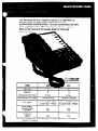
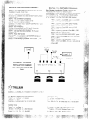
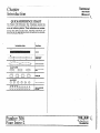
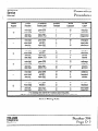
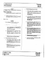
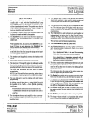
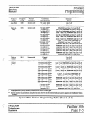
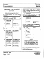
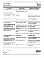
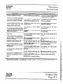
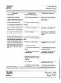
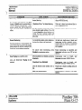
The PANTHER 306 Key Telephone System is a PANTHER 612
System which has been slightly downsized to better
accommodate smaller business. For your convenience, the table
below highlights major differences between the two systems.
Refer to the reverse of this Update Sheet for Technical
Specifications.
ITEM
CO Lines
Stations
Attendants
6
12
6max
(BLF Sets)
’
I
I
6 max
Key Service Unit Types
Tone/Rot Only
Set Types
3 Line/6 DSS - NHF
3 Line/6 DSS - HF/BLF
6 Line/l 2 DSS - NHF
6 Line/l 2 DSS - HF/BLF
No
No
Yes
Yes
FEATURES
External Page
Loud Bell
I
Tone or Tone/Rot
I
OPTIONS
SMDR
NOTE:
ICM = intercom,
NHF = Non-Handsfree,
Tone/Rot = Tone/Rotary
No
Yes
BLF = Busy Lamp Field, HF = Handsfree
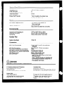
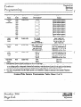
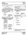
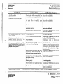
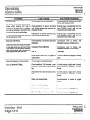
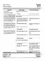
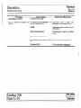
System Capabilities
Outside Lines
PANTHER Sets
Intercom Speech Paths
Attendant Sets
Door Modules
Power Fail Transfer
3 (2 with Door Answer)
c
5
6 max
2
1 Unit transfers 3 outside lines
to 3 standard phones
Power
AC Power Req.uirements
Station Loop Limit
110 Volts 2 10% (SO/60 Hz)
1 Amp max load
240 ohms max
(Equivalent to 2000 feet 24 AWG)
Environmental
Operating Temperature
Relative Humidity
Signaling
32°F to 104°F (0°C to 40°C)
9Ooh or less, non-condensing
Rotary Dial and/or Tone Dial
Number Plan
Station Numbers
10 to 15
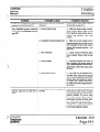
Connectors
KSU Line Connectors
KSU Set Connector
KSU External Battery Connectors
KSU Door Answer Unit Connector
KSU Power Fail Transfer Connector
KSU Music Input
Set Connector
Lines 1 and 2, and 3 -4-conductor
modular
Sets 10 to 15 - 50-pin connector
Clips
6-conductor modular
4-conductor modular
Mono l/8 inch Mini Jack
6-conductor modular
- pins 2,3,4,5 interface to the Voice
and Data Pairs;
- pins 1 and 6 provide an interface for
connecting an external amplifier to
the speaker terminals
Specificabcms and features are sub;ect to change without notice.
U.S. Marketing
Trillium TekpMne
HeadquarterstU.S.O$berations
Systems Corporation
International
Sales
Trillium Telephone Systems kc
1675 MacArthur Blvd.,
603 March Road, P.O. BOX 1330,
Costa Mesa, C&forma 92626, Tel.: (714) 557-3300
Telex: 0534524.
Canadian
Kanaz, Ontara
Tel.: (613) 592-2550.
K2K 1X3
Fax: (613) 592-2555
I
Sales
Trillium Tetephone Sales Inc.
@ Copyrght 1987 TRILLIUM Telephone Systems MC.
155 Gordon Baker Road, Suite 206, WIllowdale,
TM Trademark of TRILLIUM T&phone
Systems II-C.
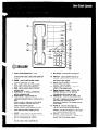
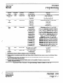
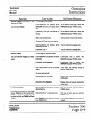
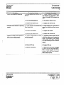
Station Select/Speed
Call - dualfunction keys used to make intercom paging
9
announcements and to dial private speed call
numbers.
Redial - used to redial the last number
10
manually dialed from your Set.
Line - used to select any of the outside
lines (unless programmed otherwise).
11
12
Hold - places outside calls on hold and
exclusive hold.
Conference
- for setting up three-party
13
add-on conference calls.
Flash/Cancel
- programmable as a
calibrated hookswitch flash or cancel, but not
14
both:
Flash
provides a calibrated on-hook signal
which is required to access most PBX,
Centrex and network features.
Cancel is used to cancel external calls and
return dial tone without hanging up the
handset.
Speed - used to enter pnvate and common
speed call numbers into the system’s memory;
also for dialing speed call numbers.
Speaker - turns the Set’s speaker on and
off; also used to end a handsfree call.
15
16
Mic On/Off - turns the Set’s microphone
on and off for handsfree calls.
Intercom - used to perform internal call
transfers, activate paging, background music
and various other features.
Ringer Volume Control - controls the
volume of the tone ringing.
Speaker Volume Control - controls the
volume of the speaker audio.
Station Indicator Lamps - (Panther 306
Attendant Set only) - turn on when the
corresponding Set is busy on a call.
Asterisk (Jt) - when the * is dialed as ‘4%
first digit in a telephone number sequence the
last outside line used at your Set is
automatically selected. (The handset must be
in the cradle).
Pound (#) - when the # is dialed, the
internal intercom line will be automaticalty
selected, provided the handset is in the cradle
and all speech paths are not in use.
Handset - used to place call5 in the
conventional handset manner. Provides more
privacy man the handsfree method.
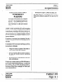
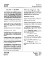
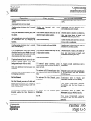
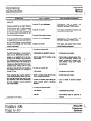
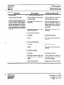
To use most of the PANTHER 306 system features, follow
the PANTHER 612 operating instructions given in the
PANTHER User Guide and the PANTHER Quick Reference
Guide. PANTHER 306 system features which operate
differently are described below.
Private Speed Call - Dialing
To speed
call one of your first 5 Private numbers
-
Lift the handset.
Press the Line key of an outside line.
Handsfree
- Turn the MIC. on/off indicator on.
Handsfree
- Press the Line key of an outside line or press *
l
l
Dial tone is heard; line indicator winks.
Press desired Speed Call key_(DSS keys 11-15).
The number is automatically speed dialed.
OR
Door Answering
To speed call one of your last 6 Private Speed numbers
l Lift the handset.
Press the Line key of an outside line.
Handsfree
- Turn the Mic. on/off indicator on.
Handsfree
- Press the Line key of an outside line or press Jt.
Dial tone is heard; line indicator winks.
l Press the Speed
key.
l Dial the desired
Speed Call Code (from 05 to 10).
The number is automatically
speed dialed.
Private Speed Call - Storing
To store your first 5 Private Speed Call entries l Press the Speed
key.
Continuous tone is heard; intercom indicator winks.
l Press the desired
Speed Call key (11-15).
Intercom indicator flashes.
l Dial the entry to be stored
including any pauses, halts, flashes.
Maximum 26 digits.
l
Contmuous tone stops; indicator continues
Write the entry on the designation card.
l
Repeat above procedure
to flash.
for each entry to be stored.
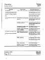
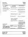
Features
Line key 3 is used to access the Door Module.
To answer a door call (from either Module) Distinctive tone ringing is heard. Line 3 indicator flashes.
l Lift the handset;
press Line key 3.
Handsfree - Turn the Mic. onloff indicator on; press Line key 3.
tine 3 indicator winks.
The visitor at the door need only speak in the direction of
the Door Module.
To place an intercom call to Door Module One l Lift the handset;
press Line key 3.
Handsfree - Turn the Mic. on off indicator on; press Line key 3.
. One ringing burst is heard; line 3 indicator wrnks.
l Make your announcement.
The called party answers by speaking in the direction of
the Door Module.
To end a Door Module
conversation
Hang up the handset.
Handsfree
- Press the Speaker key.
-
l
Line 3 indicator turns off.
that do not apply to the PANTHER 306 System:
Music through
external
Non-appearing
line access
Call Data Recording
Specrficaf/ons
To store your last 6 Private Speed Call entries l Press the Speed key.
Continuous tone is heard; intercom indicator winks.
l Dial the desired
speed call code (05 to 10).
Intercom indicator flashes.
l Dial the entry to be stored
including any pauses, halts, flashes.
Maximum 26 digits.
Continuous tone stops; indicator continues to flash.
l Write the entry on the designation
card.
l Repeat above
procedure for each entry to be stored.
paging SyStetII
operations
Cell the attendant
Message
by dialing 0
waiting from the attendant
Loudspeaker
Paging
and features are subject lo change without notice.
U.S. Marketing
Headquarters/U.S.Operations
Trlllwm T&phone
Systems Corporation
International Sales
Tnllwm Telephone Systems Inc.
1675 MacArthur Blvd.,
603 March Road, P.O. Box 13030, Kanata, Onlano. K2K 1X3
Costa Mead. California 92626, Tel.: (714) 557-3300
Telex 053-4524, Tel.: (613) 592-2550,
Canadian
Fax: (613) 592-2555
Sales
TrGum Telephone Sales Inc.
@ Copynght
I 55 GordonBaker Road. Suite 206. Wlllowdale.
TM Trademark of TRILLIUM
Ontano, M2H 3N5
Tel.: (416) 494-0522
91-0363-2A
F-301 4-l
1987 TRILLIUM
Telephohe Systems Ix.
Telephone Systems Inc
- March 1987 - Pnnted in Japan
F
1
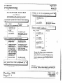
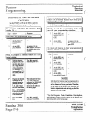
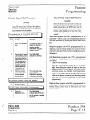
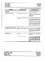
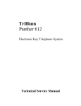
Side One of the PANTHER
612
Electronic
Key System
installation
Guide
provides
a detailed
illustration
olus stepby-step instructions
for mount,ng
and
connecting
PANTHER
612 components.
Some of these components
V/I not be used
when connecting
only the PANTHER
306
System.
Component
differences
are shown
below.
Refer to the reverse o’ this Update
Sheet. for changes
to installar’on and
programming.
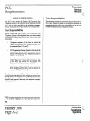
Due to the similarity between
the
PANTHER
306 and PANTHER
612 systems,
MOST of the installation
and programming
instructrons
found on the PANTHER
612
Electronic
Key System
installation
Guide
will apply to both systems.
This Update
Sheet outlines
all differences
which must be
taken into considerarron
when installing
and
proaramminq
the PANTHER
306 System
bNcY.
When following
this update-refer
to
the PANTHER
612 Electronic
Key System
Installation Guide included with your
system.
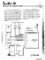
Incoming,C.O.iPBX/~entrex
v
f
Line 3 R G
Door
Answer
Unit
PAW
Lines
&conductor
Line 1 R G
Line 2 B Y
cable
supplied
DOOR
MUSIC SOURCE e
See the Power
on reverse
Fail Installation
Diagram
for
details.
connection
MUSIC
POWEF
PANTHER 306
Key Service Unit
=IIL
STATUS
. ;)R(-JG= 1’.’
1 DROG=“.’
j
.
13*n::.
RESET
Main
Distribution
Frame
50-pin
Standard
or Attendant
Set
Set
ribbon
WW
I
STATIC’.5
plug
10 to 15
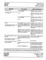
INSTALLATION
PROCEDURE
(Refer to the PANTHER
lnsta//arron
G&e,
S/de
CHANGES
612 Electron/c
One)
-
Key System
STEP 2 - Telephone
Line Connection
Do not COI!~HX! :clephone
Irr~e 3 when Ihe Door AnswcrrnG
Oo\ron
IS bcrny rrxi&x
STEP 3 - KSU to 66-Block
Connections
The KSU ;wr :.z.1or IS labelled “SLattons 10-15”.
STEP 5 - Statron
Wiring
Connections
Ignore SIZ:,G~! Vi,irnbers
16 IO 21 and DRY CONTACTS
LA:“1’~ or,
the StaIror
Wjr,c~g CharI
STEP 6 - Door Answering
The Door ir!swerrrlg
Option uszs C.O. lrne 3. Ewurc
[ha:
lelephoric
..:ii’ 3 s no! connecreo
to Ihe KSU.
STEP 7 - Call Data Recording
Interface
- Not Equlppes
Ignore 1t11s s!e:
STEP 9 - Power
Fail Transfer
Only on’c P’T .:;II IS connecwc
!o the PANTHER
306 SYS:~T.
Correct
rns:a!‘a! 3n IS shown w:ow.
..?ore
STEP 11 - External
Pagrng
Amplifier
- NOI Eourpped
lhrs sleo.
Side Two ;! the PANTHER
612 Electronic
Key System
Installation
Guide contains
the
necessary
infer-nation
for selecting
and
programmlng
s,stem features.
as well as tnformation
on :roubleshoz:,ng.
The followrng
changes
apply
wFen progran-ung
the PANTHER
306 System:
l
Whet
:‘j,,ra~nm\.
and III
l
.f’~or’:
Wher
BELL
l
; Coce 0000, qncri
INo LOUD BELL
;~x4rawrnrr:j
P ‘.GING
Coae
Whe!’ r’~yramnwy.
Ignore
111Inter:: -. LE3 ior CoUe
all of c:a:< 2YYl
Wher-
r-~yrammrng
-ED
of Coaf
6221
lgruri:
all LOUD
all of Cooe
0061.
does not apply.)
RINGING
ASSIGNMENT.
l
interco-.
5Xx0.
rr::owat1on.
Srarl Dz.2 Reczrdq
Wher I-sgra’wirrq
l
81Line 3 LED
‘?diure CXISIS )
:-;yra:‘lnw_:
Coci: 3YYl (ZONE PAGING).
3;I zone 10’3rn-~a:lon a!ler Zorw 6
Whe.
alsregz:
l
LE3
2YY0
LINE
ror C;de
(No
Ltw
qnore
1). arid lynore
GROUPING
6220
(CDR
qoore
111
iNo Lrne 11, and Ignore
-0 KSU
.I
POWER
FAIL
I
TRANSFER
INSTALLATION
FOR
Line 1,2
C01.2
DIAGRAM
PANTHER
CC:
2 TK’ 2 TK3.4
C’.:
CNK
306 SYSTEM
ONLY
TRILLIUM
teltphsmsystefns
Spef2rfrc.c
U.S.
Trlllrurn
:.‘i
and
Marketing
Ma::,:*.-’
Costa
M51.2
-.
zre subject
Sys[e,Blvd.,
C-;lrforn~a
92625
Tel.: (714)
“,c
155 Gore:
Roac
3~ ._ 206,
*,‘.I-
:‘J5
nor :f
62:
Sales
. s.t=:er
WI:-:.A
Internationa’
Tr ..m Tele:
s ‘Czrporatrorl
Canadian
Sales
Trrllrunl T< $;’ xe
Ontarro.
10 crsnge
HeadquartersU.S.0peration.s
T+ ?I’ xe
1675
fea:,‘es
55i-3300
Tee;
h,farch
Sales
=:.;j,
:rle S;srerl:s
P 0 Bsl
0%::::.
Te;
Inc.
13030, li3nala
r?:wo.
(613) 592-2555.
F& .5’3)
K2K 1X3
592-2555
.
Tel
‘1:
Wrllowda:e
494-0522
‘C ,-tizoyrryh:
T k’
Tradema..
3: -:364-l;
-37
TalLLI’JM
:I TR’LLIUM
‘.larc’, 196:
Telephone
.Sys:?:,js
Telephor:?
Sys!e’--j
Prlnred I:, Cana-:
Inc
lnc
all
Technical
:::::::::::;::::“‘.......‘........................:~:::::~:~:;:::::::::::::::::::::::::::
. .. .. .. . .. .. .. .. . .. .. .. . .. .. .. .. . .*
Service
Manual
.. .. . .. .. .. .. . .. .. .. .. . ... . .. . .. .. .. .. . .. ... . ... . .. . ... . .. .. . .. .. .. .. . .. .. .. .. .. .. .. .. .. . .. .. .. . ... . .. .. . .. .. .. .. .. .. ... .. . .. .. .. . ..
.. . .. ..
. . . . . . . . . . . . . . . . . . . . . . . . . . . . . . . . . . . . . . . . . . . . . . . . . . . . . * . . . . . ** . . . . . . . *a . . . . . . . . . . . . . . . . . . . . . . . . . . . . . . . . . . . . . . . . . . . . ..--.............................................................
. .. . .
. . . . . .,...
. . . . . .._
. . . . . _. . . ..,
. . .
\.
-Panther 306/Panther
612
Electronic
Key Telephone Systems
NOTE
i.
Whenthe organizationfor this manualwas first conceived,most chapterswere
designedto includemore thanonesystem- sincea largenumberof functions,
features,andcharacteristicsarecommonto TFULLIUM’stelephonesystems.
For example,the Panther306 and612 ElectronicKey TelephoneSystemsare
very similar; coverageof thesetwo systemswas to havebeencombinedinto a
singlechapter - asevidencedby the singlePanther306/612tab.
However, interruptingthe flow of text andgraphicsto identify andexplainthe
differencesbetweenthesesystemsprovedto be too disruptive- andthepotential for readerconfusionbeganto outweighthe benefitsof sharedcoverage.
In the end,giving eachseparatesystemits own chapterwasjudgedto be much
more usefulto field installersandtechnicians(this manual’s
primary audience)
in their normalwork environment,undertheir normaloperatingcircumstances.
Therefore,the Panther306 system- and only the Panther306 system- is
the subjectof the first chapterunderthis tab (startingat the first red page),fok
lowed by the separatePanther612chapter(startingat the secondred page).
:::::::::::::::::::::=::::::::::::::::::::::::::::::::::::~:::::::::::::::::::::::::::::::::::::::::::::::::::::::::::::::::::::::::::::::::::::::::::::::::::::::::::::::::::::::::::::::
I
L.
TRILLIUM
Telephone
Systems
.................... . .~..
Technical
Service
Manual
Table of
Contents
.. .. .. .. .. .. .. .. . . .. .. .. .. .. .. .. .. .. .. .. .. .. .. .. .. .. .. .. .. .. .. .. .. .. .. .. .. . . .. .. .. .. .. .. .. .. .. .. .. .. .. . . .. . . .. .. .. .. .. .. .. ..e... . . .. .. .. .. .. .. .. .. .. .. .. .. .. .. . . .. - . ” . . .. .. .. .. .. .. .. .. .. .. . . .. . . .. .. .. .. .. .. .. .. .. .. . . .. . . .. .. .. .. .. .“... . . .. .. ...........
. . . . . . . . . . -..*--
.......
. - . . .............................................................................................................................,
. . . .........................................
... ..........................
* ...........
. ........................................
Topic
Page
Chapter Introduction
Intro-l
Intro-l
Intro-2
PREFACE ....................................................................................................................................................
ABOUTTHIS CHAPTER.. ..............................................................................................................................
QUICK-REFERENCE CHART ..........................................................................................................................
Section A - FCC Requirements
RADIO AND TELEVISION INTEW;ERENCE ......................................................................................................
HEARING AID COMPATIBILITY .......................................................................................................................
RESPONSIBILITIES .........................................................................................................................................
User Responsibiliti es. ....................................................................................................................................
Telco Responsibilities .....................................................................................................................................
A-l
A-l
A-2
A-2
A-2
Section B - System Components
STANDARD Coh4.Po~
f
..............................................................................................................................B-l
One Key Service Unit (KSU) ...........................................................................................................................
Up to Six Telephone Sets.. .............................................................................................................................
OPTIONAL COMPONENTS ................................................................................................................................
One Door Answer Unit ..................................................................................................................................
One Power Fail Transfer Unit .........................................................................................................................
Up to Five Off Premises Extension/Data Interface (OPX) units ..............................................................................
Set Stands/Wall-Mounts.. ...............................................................................................................................
Designation Cards. ........................................................................................................................................
Face Plates...................................................................................................................................................
B-l
B-l
B-2
B-2
B-2
B-2
B-2
B-3
B-3
Section C - Technical Specifications
CONNECTORS .................................................................................................................................................
ENvIRONMENTALREQUIREMENTS
................................................................................................................
POWERREQUIREMENTS ..................................................................................................................................
STATION NUMBERING PL.AN ...........................................................................................................................
SYSTEM CAPABILITIES ...................................................................................................................................
::::::::::::::::::
i.
..“.::z
::::::::
TRILLIUM
Telephone
Systems
:::::::::::::::
1
:::::
“.
:::::::
~~::::y~::::::::
::::...............
. . . . . .
. .
.
. .
.
I..........
.
. .
. .
. .
.
.
. .
. .
. .
. .
. .
. .
.
.
I-..
. -
. .
.
. .
. .
.
.
. .
. .
. .
. .
. . .
. . .
. . . .
. . . .
. .
. .
. . .
. . .
. . . .
. . . .
. .
. -
-
. .
.
. .
.
. .
. .
.
.
. .
. .
. .
. .
.
. . ..-
.
. . . . . . . . .
,,..............”
. .
. .
.
. .
. .
. .
.
. .
. .
. .
. .
. .
. .
.
.
. . ..-.-..........................................
. . . . . . . . . . . . . . . . .
C-l
C-l
C-l
C-l
C-l
. .
. .
. .
.
. .
. .
.
. .
.
. . .
.
. .
.
“......I
’Panther.306
Page i
................................. ......... .
’Technical
Table of
Service
Manual .
Contents
.............._.
.....................................................................................................................”
.........................-......-............-...................
.
.
.
.
.
.
.
.
.
.
.
.
.
.
.
.
.....
.........................
.................
.............”
............................-
:::::::::::::::::::::::::::::
........................,..............................................a.......
c
Page
Topic
Section D - Connection Procedures
<
INSTALLING THE KSU ...................................................................................................................
STEP 1:
Site Preparation. ...........................................................................................................................................
Backboard Installation ..................................................................................................................
:. ..............
System Uncrating .........................................................................................................................................
KSlJ Instalhtion ...........................................................................................................................................
CONNECTING INCOMING TELEPHONE LINES ................................................................................
STEP2
INSTALLING STATION WIRING .....................................................................................................
sTEP3:
Station Wiring Table .....................................................................................................................................
CONDUCTING THE INITIAL SYSTEM AND STATION TESTS.. .........................................................
STEP 4:
CONNECI’ING THE BACKUP BA’ITERY ..........................................................................................
STEP 5:
CONNECTING DOOR ANSWER UNIT AND DOOR MODULES.. .........................................................
STEP 6:
Door Answer Unit Installation ........................................................................................................................
Door Module Installation ...............................................................................................................................
Door Answer Unit Test., .................................................................................................................................
CONNECI’ING THE MUSIC SOURCE ................................................................................................
STEP 7:
Music Connection ........................................................................................................................................
Music Test ..................................................................................................................................................
CONNFLTING THE OPX UNIT ........................................................................................................
STEP 8:
OPX Unit Connection ...................................................................................................................................
OPX Unit Test .............................................................................................................................................
CONNECTINGTHEPOWERFAILTRANSFERUNIT.
........................................................................
STEP 9:
Power Fail Transfer Unit Installation ...............................................................................................................
Power Fail Transfer Unit Test .........................................................................................................................
INSTALLING AN EXTERNAL AMPLIFIER/SPEAKER ......................................................................
STEP lo:
D-l
D-l
D-l
D-l
D-l
D-2
D-2
D-3
D-4
D-4
D-4
D4
D-5
D-5
D-6
D-6
D-6
D-7
/
D-8
D-8
D-8
D-9
Section E - System and Set Layout
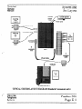
TYPICAL SYSTEM LAYOUT DIAGRAM (Standard Components only). ....................................................................
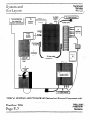
TYPICAL SYSTEM LAYOUT DIAGRAM (Optional and External Components only). ..................................................
TYPICAL POWER FAIL, TRANSFER UNIT LAYOUT DIAGRAM.. ........................................................................
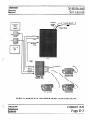
SET LAYOUT DIAGRAM ..................................................................................................................................
SETLAYOUT.. ..................................................................................................................................................
”
:::::.
‘:‘=-,‘*~:~.:~:~::::::::::::“‘.........
Panther 306
Page ii
..*....
. ..~..............:::
. . . . . . . . .* . . . . . . . . . . . . . . . . . . . . . . . . . .
:7”‘“‘:.;:
ye:
y::““‘::“““”
:::.
2::
:::::::::::
:::::::::::::::::::::.
z ::::::::::::::::::::
:”
I
:::::::::
:“:::z
::::::::::::
E-l
E-2
E-3
E-4
E-5
“<
::::::::::
::“:
TRILLIUM
Telephone
Systems
r
&
”
’Table of
Contents
Technical
Service
Manual
Section F - Feature Programming
FEATURE CATEGORIES ....................................................................................................................................
Categories Versus Codes ...............................................................................................................................
Referencing Categories to Codes ................................................................................................
. .....................
Interrelated Features .....................................................................................................................................
Feature Programming Cross-Reference Table .....................................................................................................
SYSTEM-WIDE FEATURES ..............................................................................................................................
System-Wide Feature Programming Table ..........................................................................................................
INDIVIDUAL SET FEATURES ............................................................................................................................
Individual Set Feature Programming Table. ........................................................................................................
INDIVIDUAL LINE FEATURES ..........................................................................................................................
Individual Line Feature Programming Table .....................................................................................................
INDIVIDUAL GROUP FEATURES .....................................................................................................................
Individual Group Feature Programming Table ....................................................................................................
SPEED CALL NUMBERS ..................................................................................................................................
Speed Call Programming Notes ......................................................................................................................
Common Speed Call Numbers ........................................................................................................................
Private Speed Call Numbers. ..........................................................................................................................
FEATURE DESCRIPTIONS ...............................................................................................................................
F-l
..F- I
F-l
..F- 1
.F-2
..F -4
F-5
F-8
F-9
F-10
F-11
F-12
F-13
F-14
F-14
F-14
F-15
F-15
Section G - Operating Instructions
OPERATING INSTRUCTIONS
TABLE . .. . . . . . . .. .. .. . ..a..... . . . . . . . . . . . . . . . . . . . . . . . .. . . .. . . .. .. . . .. . . .. . . .. .. . . . . . . . . . . . .. . . . . . . . . . . . . . .. . . . . . . . . . . . G-l
Section H - Troubleshooting
TROUBLESHOOTING
I
c
TRILLIUM
Telephone
Systems
TABLE.. . . . . . . . . . .. . .. .. . . . . . . . . .. .. .. . . .. . . .. .. .. .. . .. . . . . . . . . . . . . . . .. . . . . . . . . . . . . . . . . . .. . . . . . . . . . . .. .._..._....................
I
H-l
Panther 306
Page iii
Technical
Service
Manual
<
PREFACE
ABOUT THIS CHAPTER
The Panther 306 Electronic Key Telephone System is a
state-of-the-art system that incorporates sophisticated electronics to meet the communications needs of today’s home,
offke, and small business user.
This chapter has also been designed specifically to enable
technicians to install, operate, and maintain the Panther 306
Electronic Key Telephone System. Information is presented
in a logical order, without undue wordiness - to help the
technician find, understand, and use the relevant information, quickly and easily.
It connectS three outside tone or rotary telephone lines (only
two if the optional Door Answer Unit and Door Modules are
installed) with up to six station Sets - which are all wired
in a star configuration. Both Handsfree and Non-Handsfree
Sets are available; the Handsfree Sets also include Busy
Lamp Field (BLF) indicators that show the status of all system stations.
Common and private speed call numbers, call transferring,
door answering (with optional Door Answer Unit and Door
Modules), internal monitoring, conferencing (up to 3 parties), internal intercom paging (station-to-station, zone, and
all page paging), and last number redialing are just some of
the many features offered.
The attractive. well-designed system makes feature programming and operation very easy. In addition, the Panther
system is designed to allow easy interfacing with modems
and answering devices through an optional OPX device.
The fully sealed Panther 306 Electronic Key Telephone
System may be installed in either a standalone mode or behind a CENTRJSX or PBX. The microprocessor-controlled
circuitry operates all system communications and the flexible programming.
An optional external backup 24 V battery can be connected
to the system; the backup battery is automatically brought on
line in the event of a power failure, thus preventing interruptions in telephone service.
Therefore, for example, the Connection Procedures are separated into concise steps that have a logical and necessary
sequence; and reference material (Technical Specifications,
Feature Programming,
Operating Instructions,
and
Troubleshooting) is presented in a variety of easy-to-follow,
visible-at-a-glance tabular formats.
To acquaint yourself with this chapter, please review the
Table of Contents and spend a few moments browsing
through the different sections.
CAUTION
Panther equipment is sealed. Breaking the seal
will void your warranty.
If you have an installation, operation, or troubleshooting
problem that you cannot solve by using this chapter (and that
your dealer cannot help solve), call TRILLIUM Customer
Service at l-800-848-2444 (inside California, call 1-800422-7600).
NOTE
For your ready reference, a chart summarizing
indicator signals appears on the back of this
page-
Also, in the event of a total system failure, incoming lines
will be transferred to standard sets if the optional Power
Transfer Unit has been installed in the system.
TRlLLlUM
Telephone
Systems
Panther 306
Page Intro-l
1
Technical
Service
Manual
Chapter
Introduction
:::::::::::::::::::::::::::::::::::::::::::.................................................................
. .. .. . .. .. .... .... .. .... ........ .. .... .... .... ... ..................................
.. .. .. . ... . .. .. .. . .. . ... . .. . .. .,.I_ . ............,,....,...,................
. . .. .. .. . .. ..n .. . ... . .. .. .. .. . .. ... . .
.. .. .. .. . .. . .. .. .. . .. .. .. .. .. . .. .. .. . .. .. .. .. . .. .. .. .. .. .. . .. .. .. ,...I.
. . ...-...a
.. . ... ........,. ....u. .-, ... ...... ,s.. .... ...... .... .. ........-- . .. .. .... ....._.....”
c.
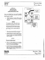
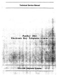
QUICK-REFERENCE
CHART
The Panther 306 Electronic Key Telephone System lets
users know what is happening witi calls and lines through a
series of indicator patterns. These indications are summarized in the chart on this page. Specific indications are
described at the appropriate places throughout the procedural material in this chapter.
cu
...- ..,~......-.......!...,
IL
-: -- ...,,._.
_.-......-" ..-. ~....-...-...--,.,,...-...-,..,,.
1I
-t
S&W WINkING
_ . ...A .. ... f .. . . . .i,‘“““’ -( .. ...*..
-:..-“---.4--A
I
0
vwyskwFusHffi
.r;;-;c
-:
&.-..A7
- I .
. ....! _....... i, ..,. _
k
I
-
Linutiuseaan
rxdu3iwhoida
anoswua~
I
Lhrhuseayous4
-p-!&
&-,&A- I *
.;.A.“‘“.+
.
TLyy..g
I
umfflhddanotu
aam
TRILLIUM
Telephone
Systems
&,
...- ............................::::::::::::::::::::::::::::::::::::::::::::::::::::::::::::::::~::::::::::::::::::::::::::::::::~
........._.................................................................
...................................................................._..........................................................................................................-............................
FCC
Requirements
.................................“‘........::::::::::::::::::::::::::::::::::::::::::::::::::::~~::::
Technical
Service
Manual
RADIO AND TELEVISION
INTERFERENCE
WARNING
HEARING
AID COMPATIBILITY
The Panther 306 Set is compatible for those requiring a
hearing aid as defined in section 68.316, Part 68 of FCC
Rules.
The Panther 306 Electronic Key Telephone
System generates and uses radio-frequency enif not installed and used in strict
ergyandaccordance with these instructions - may
cause interference to radio and television
reception.
The Panther 306 Electronic Key Telephone System has been
certified to comply with the limits for a Class B computing
device, pursuant to Subpart J of Part 15 of the Federal
Communications Commission (FCC) Rules which are designed to provide reasonable protection from radio and
television interference in a residential installation. However
there is no guarantee that interference will not occur in a
particular installation.
If interference is encountered, test to determine if the unit is
at fault by unplugging the Key Service Unit (KSU) from the
wall outlet..
If unplugging the KSU removes the interference, try the following corrective measures, singly or in combination, until
the interference is eliminated:
l
Change the location or position of the indoor receiving antenna of the radio or television.
.
Relocate the Panther 306 Set or KSU in relation to
the radio and television receivers experiencing
interference.
.
Plug the KSU into an outlet that does not also serve
radio or television sets.
If further help is needed, consult your TRILLIUM dealer or
an experienced radio/television technician - or refer to the
FCC’s booklet, “How to Identify and Resolve Radio-TV
Interference Problems.” It is available from the US
Government Printing Office, Washington, DC 20402 (stock
number CQ4-000403454).
L
TRILLIUM
Telephone
Systems
Panther 306
Page A-l
‘Technical
FCC
Service
Manual
Requirements
...............................................................................................................a........................................................................................-...........-..
*...........*a
....................................................*....
......a.........................................................a
.....................”
............- ...................,...........,.....,.............,.
......................................*,...
e
RESPONSIBILITIES
Telco Responsibilities
The FCC’s rules permit the Panther 306 Electronic Key
Telephone System to be connected to the telephone network
via a jack or jacks provided by the telephone company
(telco). These jacks are not provided for coin or party lines.
The telephone company is required to give you adequate notice of any changes it makes in its technical operations or
procedures that may affect the compatibility or use of your
Panther 306 Electronic Key Telephone System.
- User Responsibilities
c
Before connecting your Panther 306 Electronic Key
Telephone System to the telephone lines, you must contact
the telephone company and provide them with the following
information:
.
Telephone numbers of the lines to which the
Panther 306 Electronic Key Telephone System is to
be connected (lines 1,2, and 3)
.
FCC Registration Number (found on the side of the
Key Service Unit or KSU: tire number for the
Panther 306 Electronic Key Telephone System is
EBS7ST-71737-KF-E)
.
Ringer Equivalence Number (also found on the side
of the KSU: the number for the Panther 306
Electronic Key Telephone System is 33B)*
l
USOC jacks required (usually one Q-conductor,
RJ14 modular jack for lines 1 and 2; and one 2conductor RI 11 jack for line 3)
You also have the responsibility to disconnect a malfunctioning Panther 306 Electronic Key Telephone System from
the telephone lines until the cause of the malfunctioning is
identified and repaired. Otherwise, the telephone company
may temporarily disconnect service.
* The Canadian Department of Communications load number for the Panther 306 Electronic Key Telephone System is
16B.
, . ... .. . .. .. .. .. . .. ..
,..............,......
-
“::::::::::::::::::::::::::::~~:::::::~~:~~:::::::::::::::::::::::::::::::~:;:::::::::::::;:~:::::::::::::::::~:::::::::::::::::::::::::::::=::::~~=:;::::::~:::::::::::;:::::::”:::
Panther 306
Page A-2
I
TRlLLiiJM
c ...<.1,
Telephone
Systems
..............................................................................................................-....
.............................................................................................................................................................................................*........................-..- .....................................................................................................”........,......:::::::::::::::::::::::::::
Technical
Service
Manual
System
Components
.,..................................................................
.................................*...a
..........................- .........................................
...................:::::::::::::::::::::::::::::::::::::::
STANDARD COMPONENTS
One Key Service Unit (KSU)
Part Number 90-0290 (tone/rotary)
The key service unit (KSU) for the Panther 306 Electronic
Key Telephone System can be programmed to operate with
either dual-tone, multi-frequency (DTMF) or rotary (pulse)
signaling. The signaling on each Central Office (CO) line
can be programmed independently. The KSU has two connectors on its left side to attach the three incoming telephone
company (telco) CO lines - one connector for lines 1 and 2;
and a second connector for line 3 (which must be left vacant
if the optional Door Answer Unit is installed).
Also on the left side of the KSU are connectors labeled
DOOR (for the optional Door Answer Unit), MUSIC (for an
external music source), POWER FAIL (for the optional
Power Fail Transfer Unit).
Below these connectors, the KSU has one recessed lightemitting diode (LED) indicator (labeled STATUS), four
miniature dual m-line package (DIP) switches (labeled, from
top to bottom, 1 PROGRAM [used to return features to their
default, factory preprogrammed conditions], 2 PROGRAM
[used to program system features], 3 [not used], and 4
BATIERY [used to save feature programming]), and one
recessed pushbutton (labeled RESET).
Near the bottom left of the KSU is a 50-pin connector, labeled STATIONS 10 TO 15, that is used to connect the
KSU to the station wiring main distribution frame (MDF) and, through the h4DF, to all the system stations.
Up to Six Telephone Sets
Part Number 90-0291
(non-handsfree)
k-t Number 90-0292
(handsfree with busy lamp field)
Other than the handsfree operation and the busy lamp field,
these two models look alike and operate identically. For example, both have an attractive black matte finish.
Each Set’sbase has six dual-function station select/speed
dial keys (labeled 10 through 15 - the top key is also used
for last number &dial), three line select keys (labeled 1,2,
and 3), seven dedicated function keys (labeled Hold, Flash/
Cancel, Conference, Intercom, Speed, Speaker, and
Mic.on/off) and a tone dial keypad
The line 1,2, and 3 keys, the Intercom
key, and the
Mic.on/off key have accompanying status indicators. And,
only on handsfree/busy lamp field (HF/BLF) Sets, each station select key (10 through 15) also has an accompanying
status indicator.
Finally, the base has a speaker volume control (a sliding adjustment) and a ringer control switch (a 3-position switch,
for low, medium, and high volume ringing).
Each Set also includes a telephone handset and two modular
cords - a 4-conductor, coiled cord for connecting the handset to the Set, and a 4-conductor modular cord for
connecting the Set to the station wiring jack.
The KSU’s power cord (at the top of the KSU) plugs into a
110 V ac outlet (at the appropriate time; see the Connection
Procedures section). A grounding wire (12 AWG, solid cop
per) connects from the top of the KSU to a ground clamp,
usually on a water pipe.
An input connector for an optional 24 V backup battery is
also provided at the top of the KSU. If ac power is lost, the
switchover to backup battery power is automatic when the
optional backup battery is connected.
The unit comes with 4 screws for mounting the KSU on a
backboard.
.
s<~;: TRILLIUM
Telephone
Systems
I
Panther 306
Page
B-l
.- ....................................................-.....................................................
._-..........._..........................................
.....“:::::::::::::::::...-.---........
-.*...-----...- ...
_.. .
. . . . . . . . . . . . . . . . . . . . . . . . . . . . . . . . . . . . . . . . . . . . . . . . . . . . . . ..-.........
. . ... . .. .. .. .. . .. .. .. .. . ... .. . .. .. . .. .. . i.. .. . .. .. .. . .. . .. .. .. .. .
.
:::::::::::::::::::::::::::::::::::::::::::::::::::::::::::::::::::::::::::::::::::::~:::::::~~:.~
::::
::I’:.-
-.:::-““:~::::::I:::::::::::::::::::::::::::::::::::~::::::::::::::::::
Technical
System
Service
I’
Manual
Components::::::::~::::::::::::::::::::::::::::::::::::::::::::::::::::::::::::::::::::::::::::::::~~:::::~:~::::~::::::::
..._....................................................
.....................................”
...............
.
<
OPTIONAL COMPONENTS
One Door Answer Unit,
Part Number 90-0058,
With One or Two Door Modules,
Part Number 90-0057
The Door Answer Unit (also known as the Door Answer
Control) is installed next to, and connects with, the KSU. It
serves as the interface between the system’sstations and the
one or two installed Door Modules (also know as the Door
Answer Boxes) at the desired doors or entryways. Together,
these units enable signaling and conversation between Set
users and visitors. Like the KSU, these units come equipped
with mounting screws.
A visitor, by pressing the door bell button on a Door
Module, generates a distinctive tone (four groups of 4 short
tones for Door Module 1, four groups of 2 long tones for
Door Module 2) that wilI sound at all Sets programmed to
ring on line 3 and causes the indicator for line 3 on all Sets
to WINK. Also, each Set user can generate a calling tone
that will sound at Door Module 1 only.
One Power Fail Transfer Unit
Part Number 90-0052
The Power Fail Transfer Unit automaticalIy takes over in the
event of an electrical power failure, allowing for continued
telephone service during the emergency. When power fails,
the Power Fail Transfer Unit transfers the system’sCO lines
(all 3 of them - or the 2 lines in use, if the optional Door
Answer Unit with Door Modules is instaUed) to pre-installed
standard telephone sets (nor to Panther 306 Sets).
~:::~:::::::~:::::::::::::::::::::::::::::::::::::::::::::::::
c
Up to Five Off Premises Extension/
Data Interface (OPX) units
Part Number 90-0308
The OPX unit convertS a 4-wire interface to a 2-wire interface, allowing a single line telephone to be connected to any
spare station jack -except station 10. It also allows 2-wire
devices to be connected at a distance greater than the system
2000 feet limit for Sets. The OPX unit also simulates CO
line characteristics, allowing a modern or an answering machine to be connected to the system. Finally. the OPX unit
allows a remote device to be connected to your system at
anydistanceviaaCOline.
When the user lifts the singleline telephone’s handset, an intercom connection is made to the Panther system. Also, by
dialing a special code, the off-premise user can access any
of the Panther system’soutside limes.
Set Stands/Wall-Mounts
Part Number 90-0087
Each Set may be placed on a desk - or mounted on a wall
using the Set Stand/Wall-Mount Bracket (available in packages of 10).
The same bracket can also be used to provide a heightened
viewing angle when used with the Set on a desk- or tabletop*
..................-,::-’
- :::::::::::::-~:::::::::-‘:::::~~~:::;:::::::~~~~::~~.-~~”~:~::~
__I-...
-“”..-. “.~....__
:::::n:~“-........--”
_I.“...“.....“....
::c
TRILLIUM
i;$‘.;;
c
Panther 306
Page B-2
Telephone
Systems
!
‘..
<
System
Components
.
.
.
.
.
.
.
.
................................... a. ..................................................................::::::::::::~:::::
Technical
Service
Manual
Designation Cards
Part Number 90-0296
(for non-handsfree Sets)
Face Plates
Part Number 70-0211
(for non-handsfree Sets)
Lrt Number 90-0297
(for handsfreelbusjl lamp field Sets)
&-t Number 70-0212
(for handsfree/busy lamp field Sets)
Designation Cards are used to list the first five private spe43d
call numbers and identify the assignment or location of the
six system stations.
Face Plates cover and protect the Designation Cards. You
may order spare Face Plates for your system.
Notice that each type of Set uses a diJkrenf Face Plate.
Although each Set comes equipped with one installed and
one spare Designation Card, you may order additional cards
(in packages of 10) for your system.
Notice that e&h type of Set uses a different
TRILLIUM
Telephone
Systems
Designation
Panther 306
Page B-3
L
Technical
Service
Manual
Techni cal
Specifications
.
.
.
.
.
.
.
.
.
.
.
.
.
.
..-..................-................
:::““:::::::::::
:::::
:::::::::::::::::::::::::::::::::::::
::::::::
::
::::::::::::::::::::::::::::::::=:::
;:::::::.::::
:::::::::::::::::::
::::::::::::::::::::::::::::::::::::::::::A
.,..........................-........,.........-.........-....
CONNECTORS
<
Equipment
JackslConnections
Cable Ptis
CO or PBX lines . . .. .. . . .. . .. . . .. .. .. .. . .. . . .. .. . .. .. . .. . .. . . .. . ..
KSU:
C01.2 and CO3 . .. . .. . . . .. . .. . .. . .. . .. . . .. . . .. .. .. . ..-.......
STATIONS 10 TO 15 (to station wiring MDF)....
DOOR (to Door Answer Unit jack DA) .. .. ... . .. ... ..
POWER FAIL (to Power Fail Transfer Unit) .. ... ...
MUSIC (music input - 50 mV rms) . .. .. .. . .. . ... . .
External battery . . .. .. .. . . . .. . .. . .. .. . . . . .. . .. . ... .. ..-........
Ground .. .. . . . . . . . . . .. . . . . . . .. . . . . .. . . .. . . . . . .. . . . .. . . . .. . . .. . . . .
Station wiring MDF (to station jacks) . ... ... .. .. .. .. . . .. ... .
Panther 306 Sets (to station jacks) . ... . .. ... ._... . ..._........
Door Module (to Door Answer Unit Dl and D2) ._........
Power Fail Transfer Unit (optional):
C01.2 & C03.4 (from incoming lines) .. ...__........
TK1.2 & TK3.4 (to KSU jacks C01.2 & C03.4).
CNJ (to KSU jack POWER FAIL) .. .._......._........
Modular RJ14C and RJllC ... .. ..
A total of 3 (one per line)
Modular RJ14C and RJllC ......
50-pin R21C to 66-block.. ........
Modular RJ25C.. .....................
Special connector.. ...................
Mini-Jack (1/8-&h, phono). ......
Molex connector ......................
Screw terminal ........................
66-block to modular RJ14C.. .....
Modular RJ14C (or RJ25C**) ....
Screw terminals.. .....................
2andl
25
3
(See Power Fail Transfer Unit)
1
1
Single 12 AWG, solid copper wire
2 each*
2 each, cord supplied (or 3**)
1 toeachmodule
Modular RJ14C and RJllC.. .....
Modular RJ14C and RJllC.. .....
SpeciaI connector.. ...................
2andl
2andl
1 (cable supplied)
ENVIRONMENTAL
REQUIREMENTS
Operating Temperature .. . . . . .. . . . .. . .. . . . .. .. . .. .. . . ..--..........................................................
Relative Humidity . . . . . . .. . . . . . . . .. . .. . . . . . . .. . . .. . . .. ..--..........................................................
0 to 40 “C (32 to 104 “I!)
Less than !9t?%,non-condensing
POWER REQUIREMENTS
Voltage . . . . .. . .. .. . . . . . . . . . . .. . .. . . . . .. . . . . .. . . . . . .. . . . .. . ..---........................................................
Current . . .. . .. .. . . . . . . .. . .. . . . . . . . . . . . .. . . . .. . . . . . . . . ..-......--.......................................................
STATION NUMBERING
115 V ac (* 10%). 50/60 Hz
1.0 A, maximum load
PLAN
Panther 306 Sets or OPX units . . . .. . .. . .. . .. .. ..---.....-......................................................
10 through 15 (OPX unit not allowed on station 10)
SYSTEM CAPABILITIES
CO or PBX Lines (each independently programmable for DTMF or pulse signaling) ...........
Intercom Speech Paths ............................................................................................
Stations (any mixture of non-handsfree and handsfree/BLF Sets or OPX units). ..................
Speed CaU Numbers (up to 26 digits, pauses, or flashes each):
Common (system-wide) ....................................................................................
Private ...........................................................................................................
Door Answer Unit (optional) ...................................................................................
Power Fail Transfer Unit (optional) ...........................................................................
3 (only 2 with Door Answer Unit)
3
Up to 6
Upto
-.
Up to 11 at eachSet
1 (with 1 or 2 Door Modules)
1-t
* Length of each station cable should not exceed 2000 feet of 24 AWG; all station runs are star (horae run) configurations
** Sets may ahernatively use a 6-conductor modular cord-to-RI25C jack (to gain access to the Set’sspeaker terminals)
t Transfers up to 3 incoming lines to pre-installed standard telephone sets (not Panther 306 Sets) in the event of a power failure
TRILLIUM
Telephone
Systems
Panther 306
Page C-l
. . . . . . . . . . . . . . . . . . . . . . . . . . z ::::;:::::::::
,. . . . . . . . . . .
::::::::
::::
. .. . . .. ... . .. ... .. . .. ... . . ...
. . . . . . . . . . . . . . . . . . . *a . . . . . . . . . . . . . . . . . . . . . .
:::::::::::::::::::::::::::::::::::::::::::::::::::::~:::::::::::::::::::::::::::::::::::::::::::::::::::::::::::::::::::::::.~::::::::::::::::::::::::::::::::::::::::::.:~::....-........
Technical
Service
Manual
Connection
Procedures
.....a.
...._..........
_
.._.._..............................................................................
,
.
.
.
.
.
.
.
.
.
.
.
.
.
.
.
.
.
.
.
.
.
.
.
.
.
.
......“...I
.......,.........,....
...................
.......“.......................................................................
*.........#...................... .-....
...........
STEP 1
INSTALLING THE KSU
Site Preparation
Because the KSU is at the heart of the operation of the
Panther 306 Electronic Key Telephone System, ensure that
its installation site meets the following criteria:
SystemUncrating
a
Carefully unpack the System and confirm that all
ordered parts are present by checking them off
against the Customer’s order sheet and the packing
list.
h
Make sure that the customer’s feature requirements
have been documented on a Customer Feature
Selection Form.
Clean, dry, and well ventilated (should meet the environmental requirements listed in Section C)
l
.
Within seven feet of the incoming CO, CENTREX,
or PBX line terminations
WARNING
If you are in area subject to power transients,
instali a surge protector on the dedicated outlet.
.
Within five feet of a dedicufed 110 V ac, 60 Hz, 3wire grounded outlet - an outlet that is not on a
wall switch
.
Not too distant from station terminations (the maximum distance to each station is 2000 feet, using 24
AWG wiring)
.
A 30” by 30” area of wall space should be reserved,
allowing room for the Power Fail Transfer Unit and
Door Answer Unit (whether they are being installed
now or might be in the future)
KSU Installation
a
Mark the position of the 4 screw holes needed to
mount the KSU on the backboard.
b.
Drive four screws (supplied) until their heads are
within l/g-inch of the board’ssurface.
c.
Using the four keyhole slots (narrow end up) in the
side flanges of the KSU cabinet, hang the unit on
the four screws and tighten them securely.
CAUTION
Failure to properly ground the KSU may void
your Panther 306 Electronic Key Telephone
System warrantyd
Connect the ground lug at the top of the KSU to a
cold water metal pipe or ground stake, usirig copper
wire that is 12 AWG or heavier (not supplied).
Be sure that the cold water pipe’s metal continuity
is not broken by the use of plastic pipe.
Backboard Installation
If the KSU is to be mounted on a concrete or masonry wall,
the use of a l&inch thick plywood backboard (30 inches
square) is recommended.
Depending on the wall’s construction and your method of installing the backboard, you might need screwdrivers
(various kinds and sizes), drills and bits (various sizes), # 10
masonry screws with plastic anchors (4 of each), or l/4”
screws with wall grip screw anchors (4 of each).
Aground stake should also meet the &allation
quirements of your local electrical code.
e
re-
At the electrical service panel, equip the electrical
breaker for tbii outlet with alocking clip - or
mark it with a label to serve notice that this unit
should not be disconnected or shut off.
Mount the backboard at least 12 inches above the floor.
. .
. .
.
. . .
. .
. ..“.......
. . . . . .
.
. .
“”
. . ...““..”
. ..-._“......“”
. .
.
.
. . . .
. . . .
. .
. .
. .
. .
.
.
. .
. .
.
.
. .
. .
.
.
. .
. .
. .
. .
. .
. .
.
.
. .
. .
. . . . . .
. . . . . .
.
.
. .
. .
. .
. .
. .
. .
. .
. .
. . . . .
. . . . .
. .
. .
.
.
. . . .
. . . .
. .
. .
. .
. *
. .
. .
. .
. .
. .
. .
. .
. .
. . .
. . .
. .
. .
. :::::::::::::::::::::::::::::::::::::::::::::::::::::~~::::
.
:::“::
zv::.“.I”::zFG
:::::“::::
r G : “ . *y*wz
::::
_~
::“::
““&
::::::“::::;
,’
.. TRILLIUM
Telephone
Systems
Panther 306
Page D-l
.”.......”
....a”““................
.......................s..........::::::::::::::::::::::::::‘;:::::::::::~::::::::::::~~::~
__“_“.....................,..................................
Technical
Service
Manual
Connection
Procedures
STEP 2
CONNECTING
INCOMING TELEPHONE LINES
STEP 3
INSTALLING STATION WIRING
WARNING
WARNING
Do not plug in the KSU’s power cord until instructcdtodosoinStep4.
To prevent damage to the KSU while wiring,
make sure that the KSU’s power cord is not
plugged in. Do not apply power to the KSU
until instructed to do so in Step 4.
NOTES
1. If telephone lines 1 and 2 are not yet installed, ask the telco that they be terminated in
a single 4-conductor RJ14 jack.
2. If line 3 is also not yet installed, ask that it
be terminated in an RJ 11 jack
3. If the optional Power Fail Transfer Unit is to
be installed, follow the instructions in Step 9 to
connect the incoming lines.
4. If the optional Door Answer Unit is to be installed, line 3 (KSU jack C03) must be left
vacant
NOTES
1. Because much of the feature programming is
performed from station 10, choose a convenient or strategic location for station 10.
2. If an external amplifier/speaker is to be used
at any of the station locations, mount a 6conductor RJ25 jack at the station lazation instead of a 4conductor RJ14 jack See Step 10.
3. Refer to the Typical System Layout
Diagram (on page E-l) and the St&at Wiring
Table (on the facing page) for wiring details
i
5. Refer to the Typical System Layout
Diagram (on page E-l) for wiring details.
Decide on the location and station number (horn 10
up through 15) for each Set.
If the incoming lines are terminated in RJ14 jacks - with
lines 1 and 2 terminated in a single RJ14 jack - simply install one rl-conductor, modular line cord between the single
RJ14 jack at which incoming lines 1 and 2 both terminate
and the jack labeled C01.2 on the left side of the KSU.
Mount a 4conductor RJ14 jack within 6 feet of the
desired Set location at each station.
If, however, the incoming lines 1 and 2 are already tenninated in separate RJll jacks, use a 2-line to modular RJ14
adapter (such as SE-174 from Suttle Apparatus Corporation)
to form a bridge to the KSU jack labeled C01.2.
Install a 25-pair cable - with male 50-pin connectors at both ends - between the 66block’s 50-pin
connector and the KSU 50-pin connector labeled
STATIONS 10 TO 15. Secure the KSU end of the
cable with the screw and plastic tie-wrap provided
with the unit.
Then, install a 2conductor modular cord between the RJl 1
jack at which incoming line 3 terminates and the jack labeled CO3 on the left side of the KSU.
On the backboard, mount a 66-block with a female
50-pin connector.
For each station, install a.length (not to exceed
2000 feet) of 4-conductor, 24 AWG~cable fiom.the
66-block terminals to the station wiring jack
..........................................................__
. .............................................._........................,..................................................................................
.
panthap
LLllbl
.
.
. . . . .
. . . .
. . .
. . . . .
. . .
2nA
JVU
Page D-2 .
. . . . . .
. . . .
. ...”
. . ..__..........................................................................................
I
.
. .
. . . .
. . . . . .
. .
TRILLIUM
Telephone
Systems
(
-.
I
\
Technical
Service
Manual
Connection
Procedures
..........................................._._.................................................................................................................................................
- ..................................................................................................
........................
a. . . . . . . . . . . . . . . . . . . . . . . . . . . . . . . . . . . . . . . . . . . . . . . . . . . . . . * . . . . . . . . . . . . . . . . . . . . . . . . . . . . . . . . . . . . . . . . . . . . . . . . . . . . . . . . . . . . . . . . ..-.................................................................................................
station
Number
Circuit
Function
CConductor
Station Jackt
66-Block
Terminal
SO-Fin
Connector
25 Pair
Cable*
10
voice (tip)
voice (ring)
green (GN)
red W)
1
2
26
1
white/blue
blue/white
data (tip)
data (ring)
black (BK)
yellow (YL)
3
4
27
2
white/orange
orange/white
voice (tip)
voice (ring)
green (0
red (RD)
5
6
28
3
white&mm
green/white
data (tip)
data (dg)
black (IX)
yellow (YL)
7
8
29
4
white/brown
brown/white
voice (tip)
voice (ring)
green (GN)
red(RD)
9
10
30
5
white/slate
slate/white
data (tip>
data (ring)
bbk (BK)
yellow VU
11
12
31
6
red/blue
blue/red
voice (tip)
voice (ring)
green (GN)
red W)
13
14
32
7
red/orange
orange&xi
data (tip)
data (fig)
bhk 0
yellow W)
15
16
33
8
red/green
gredred
green (GN)
red NJ)
17
18
34
9
red/brown
brown/red
bkk
(BQ
yellow
02)
19
20
35
10
11
12
13
14
voice (tip)
voice (ring)
data (tip>
-
15
w%)
red/Slate
Sk-it&t?4l
voice (tip)
voice (ring)
green (GN)
red@))
21
22
36
11
black/blue
blue/black
data (tip)
data (ring)
bkk 0
Wow (n)
23
24
37
12
black/orange
orange/black
t Use match@ color codes fix the 4amductor station wiring cables.
* The first color listed is the predominant color, the second color listed is the n-aca or stripe color.
Station Wiring Table
TRILLIUM
Telephone
Systems
-.
Panther 306
Page D-3
Technical
Service
Manual,
Connection
Procedures
::::::::::::::::::::::::
~.:::::::::::::::::::::::::::::::::;
:::::::::::::::::
:::::::::::::::::::::::”
.
.
.
.
.
.
.
.
.
.
.
.
.
.
,
.
.
.
.
.
.
.
.
.
.
.
.
.
.
.
.
.
.
.
.
.
.
.
.
.
.
.
.
.
-
,..I
STEP 4
CONDUCTING THE INITIAL
SYSTEM AND STATION TESTS
NOTE
If the indications described below do not
occur, refer to the Troubleshooting section.
.
.
.
.
.
.
.
.
.
.
. . . . . . . .
.
.
.
.
.
.
.
.
.
. . . . . * . . .
.
.
.
.
.
.
.
.
. . . . . . . .
.
.
.
.
.
.
.
.
.
.
.
.
.
. . . . . . . * . . . . .
.
.
.
.
.
.
.
.
. . . . . . . .
.
.
.
.
.
.
.
. . . . . . .
.
.
.
.
.
.
.
. . . . . . .
.
.
.
.
.
.
. . . . . -
-
.
.
.
.
.
.
.._
_
.
.
.
.
.
.
-
.
.
.
.
.
.
.
.
.
.
.
.
.
.
.
.
.
.
.
.
.
.
........................
-......_.....-............._...............................
k
Repeat steps i and j for line 1 used for the Dear Answer Unit
1
Repeat steps g through Ir for the remaining stations.
and line 3, if not
Unless you have optional items to install (the Door Answer
Unit, the Power Fail Transfer Unit, OPX units, or a music
source), your Panther 306 Electronic Key Telephone System
is now ready for programming or operation.
a.
Connect the KSU power cord to the surge protector
previously installed at the 110 V ac power outlet
the recessed STATUS indicator goes ON (with a
slight flicker) indicating that the KSU is operative.
STEP 5
CONNECTING
THE BACKUP BATTERY
b.
Set KSU switch 4 BATTERY to ON (if necessary,
use a paper clip or other pointed object such as a
pen or pencil to set the KSU miniature DIP
switches)
TheKSU has a white plastic Molex connector at its top for
connecting an external backnp bat&y. The backup battery
used (such as the TRI 24RSB from Alpha Technologies)
should provide 24 V de at 2 Amps for an extended period of
rime.
C
Set KSU switch 1 PROGRAM to ON.
d
Push the recessed RESET pushbutton once.
C
Set KSU switch 1 PROGRAM to OFF.
E
Push the recessed RESET pushbutton again: the
system is now set the factory preprogrammed conditions (for details on what-those conditions are, see
the Feature Programming section).
&
At station 10, plug in the 4-conductor modular cord
supplied with the set between the Set and the station wiring jack.
h
Press the Set’s Intercom key: the Set’s speaker
emits a continuous tone and the Intercom indicator
goes ON.
i
Lift the handset and press the line 2 key: dial tone
is heard: the Intercom indicator goes OFF; if
yours is a BLF Set, your station indicator goes ON;
and the line 2 indicator WINKS slowly.
j.
Hang up the handset: dial tone is removed; and the
tine 2 indicator goes OFF.
L
a
Connect the positive (+) terminal of the battery
(usually the red lead) to the left side of the KSU
connector,
h
Connect the negative (-) terminal of the battery
(usually the black lead) to the right side of the KSU
CoMector.
STEP 6
CONNECTING
.
DOOR ANSWER UNIT
AND DOOR MODULES
NOTE
If you have chosen to install the Door Answer
Unit with its one or two Door Modules, the
line connector labeled CO 3 must be left
vacant.
Door Answer Unit Installation
a
Mount the Door Answer Unit on the backboard
along with the KSU, using the four screws supplied
with the equipment
:::::::::::::::::::::::::=::::::::::::::::::::::::::::::::::::::::::::::::::::::::::::::::::::::::::::::::::::::::::::::~::::::::::::::::::~:~:::::::::::::::::~:::::::.~:::::~:::::~~~:::_~-:~:::~.~~:::~~~:::::::~~
I
Panther 306
Page D-4
TR,‘L,“M
@-#ii,
Telephone
Systems
Technical
Service
Manual
l
Connection
Procedures
.._.....__.....................,............................................................................
,..................................................................................__
..._.........................
......................“_.....................................
9 . . . . . . . . . . . . . . . . . . . . . . . . . . . . . . . . . . . . . . . . . . . . . . . . . . . . . . . . . . . . . . ...................................................................................--..........................................................
b.
ii
Connect a 6-conductor modular cord (not supplied)
to the connector labeled DOOR on the KSU and the
connector labeled DA on the Door Answer Unit.
COMeCEd.
Door Module Installation
a Remove the screw securing
...
the Door Modules’
front cover, and separate the front from the back
b.
Mount the backs of the Door Modules at the desired entryway locations, using the two mounting
screws furnished with each Door Module.
c.
Run a length (not to exceed 2000 feet) of 2conductor, 24 AWG wire from the Door Answer
Unit to each Door Module.
d
Feed the wire through the hole in the base of the
back of the Door Module.
e
Strip the cable end and secure it to the screw terrninals found on the backside of the Door Module’s
front assembly.
f.
Replace the Door Module’s cover and tighten the
screw to secure the front to the back.
g.
At the Door Answering Unit, strip the cable ends
and secure the cable from Door Module 1 to the
screw terminals labeled Dl and the cable from
Door Module 2 to the screw terminals labeled D2.
Door Answer Unit Test
Ill.
b.
NOTE
Set-initiated door module intercom calls can
only be placed to Door Module 1, not to Door
Module 2.
i
Alternatively, at any Set, pick up the handset
and press the line 3 key: the line 3 indicator
WINKS; if yours is a BLF Set, your station indicator goes ON; and the person at Door
Module 1 hears a burst of ringing.
ii.
At the entry way where Door Module 1 is installed, the person responds by speaking in the
direction of the Door Module: you and the person at the entryway am connected.
iii. At the Set, hang up the handset: all indicators
go OFF, and the call is terminated
c.
Door Module 2-initiated calling:
i
At Door Module 2’s entryway, have someone
press the door button: four groups of 2 long
tones are heard at all Sets programmed to ring
on line 3; and the line 3 indicator FLASHES
slowly.
ii
At any Set, pick up the handset and press the
line 3 key: the line 3 indicator WINKS; if yours
is a BLF Set, your station indicator goes ON;
and you and the person at the entryway are
If the indications described below do not
occur, refer to the Troubleshooting section.
Door Module l-initiated calling:
i
At Door Module l’s entryway, have someone
press the door button: four groups of 4 short
tones are heard at all Sets programmed to ring
on line 3; and the line 3 indicator FLASHES
slowly.
At the Set, hang up the handset: all indicators
go OFF, and the call is terminated.
Set-initiated calling:
NOTE
a
At any Set, pick up the handset and press the
line 3 key: the line 3 indicator WINKS; if yours
is a BLF Set, your station indicator goes ON;
and you and the person at the entryway are
COMeCti.
iii
At the Set, hang up the handset: all indicators
go OFF; and the call is terminated
.
(
\
TRILLIUM
Telephone
Systems
Panther 306
Page D-5
....*............
..................................................“
.._._..__
............................................_
-..; .......
.......__.......................
......._....
..........................................................................................................................................................................................................,......................................................................................
..........................,....................
_ ......
Technical
Service
Manual
Connection
Procedures
STEP 7
CONNECTING THE MUSIC SOURCE
Music Connection
a
Connect one end of the cable (not supplied) into the
music source’s output jack.
b.
Connect the other end, which terminates in a l/8inch mini-jack (phone, not stereo or attenuator),
into the KSU connector labeled MUSIC.
Testing the background music on hold:
c
i
Have someone call in on outside line 1 (alternatively, you can call line 1 from line 2):
ringing is heard at all stations programmed to
ring on line 1; and the line 1 indicator
FLASHES slowly.
ii.
At any station, pick up the handset and press
line 1 Key: the line 1 indicator WINKS
slowly; if yours is a BLF Set, your station indicator goes ON; and a connection is made with
the outside caller.
the
Music Test
NOTE
If the indications described below do not
occur, refer to the Troubleshooting section.
a
Turning background music on at a Ser
i
ii.
At any station, with the handset in its cradle,
press the Intercom Key: the Intercom indicator WINKS slowly; and a continuous tone is
heard over the Set’s speaker.
With the handset still in its cradle, dial * 4: the
InterCOm indicator goes OFF; and the continuous tone is replaced by background music
coming from the Set’s speaker.
...
lll. After informing the outside caller of your intentions, press the Hold key and hang up the
handser the line 1 indicator FLASHES quickly; if yours is a BLF Set, yaw station indicator
goes OFF; and the outside caller hears the
background music.
iv. After a few seconds, retrieve the call by picking up the handset and pressing the line 1 key:
the line 1 indicator WINK!3 slowly; if yours is
a BLF Set, your station indicator goes ON, the
outside caller no longer hears the background
music; and the connection with the outside
caller is restored.
V.
Confirm the success of the background music
on hold test with the outside caller.
Vi.
Hang up the handset: all indicators go OFF;
and the call is terminated.
iii. At the music source, adjust the level of the
background music for the desired loudness.
b.
Turning background music off at a Set
At any station, with the handset in its cradle
press the Intercom Key: the Intercom indicator WINKS slowly; and a continuous tone is
heard over the Set’s speaker.
_
With the handset still in its cradle, dial * 4: the
Intercom indicator goes OFF; and neither the
continuous tone nor the background music is
heard over the Set’s speaker.
TRILLIUM
Telephone
Systems
Technical
Service
Manual
:::::::::::::::::=:::::::::::::::::::::::::::::::::::::::::::::::::::::::::::::::::::::::::::::::::::::::::::::::::::::::::::::::::::
:::::
Connection
Procedures
C
STEP 8
CONNECTING THE OPX UNIT
OPX Unit Test
NOTE
OPX Unit Connection
NOTES
If the indications described below do not
occur, refer to the Troubleshooting section.
1. The OPX unit may be installed at any station
location -except station 10.
2. See also the Typical
Diagram on page E-2.
System
a
Originatingintemalcalls:
i
At the standard set connected to the OPX unit,
pick up the handset: a continuous tone is
ii
Call another station by dialing its 2-digit number, such as 13: at the called station, repeated
long tones are heard.
Layout
a
Mount the OPX unit next to the desired station location, using the four screws supplied with the
equipment
b
Plug the small dc connector into the OPX unit‘s
POWER connector and plug the wall connector
into an unswitched. grounded 115 V ac outlet
c
Connect the modular cord (not supplied) between
the station wiring jack and the KSU jack on the
OPX unit_
...
tn. The called par&picks up the handset: the tones
stop; and you and the called party are
ConneCted.
iv. Bang up the handset to terminate the call.
h
Receiving internal calls:
i
Have someone place an internal call to the station at which the OPX unit is installed: your
set rings.
ii.
Pick up the handser the ringing stops; and you
and the calling party are connected.
NOTE
If the device to be used is remotely located
(not to exceed 2 miles on a direct connection),
a 2conductor. RJl 1 jack can be mounted and
wired to the remote device.
(\.
Alternatively, the remote device can be accessed through a CO line (with no limits on
distance). FCC rules require that you tell the
telco that the OPX‘s Facility Interface Code is
OL13B and its Service Code is 9.OF.
In either case, the 2-conductor cord in step a
will then be connected between the RJl 1 jack
and the TEL jack on the OPX unit.
d
(_
Connect a 2-conductor cord between the TEL jack
on the OPX unit and the 2-line device to be used
(such as a standard set, answering machine, or
modem).
e
If access to an outside line is desired in the event of
a power failure. connect a spade-to-modular, 2conductor cord between one of the incoming lines
(in parallel with the normal system connection) and
the PFT jack on the OPX unit.
E
Set the A-B switch on the OPX unit to B.
TRILLIUM
Telephone
Systems
_
iii. Hang up the handset to terminate the call.
c
Placing outside calls:
i
At the standard set connected to the OPX unit,
pick up the handset: a continuous tone is
ii
Request outside line 1 by dialing lOl :an externaldial tone is heard
...
nL Complete the outside call by dialing the desired number. Hang up, when finished, to
terminate the call.
iv. Test access to outside line 2 and outside line 3
(unless the optional DoorAnswer Unit is installed) by repeating steps i through 5 above
for outside lines 2 and 3.
Panther 306
Page D-l
Technical
Service
Manual
Connection
Procedures
i’,,,
STEP 10
INSTALLING
AN EXTERNAL
AMPLIFIER/SPEAKER
4-conductor
StatiOnwiring
If an external amplifier/speaker is to be installed at a given
station, the the standard station wiring and Set installation
procedures must be modified for that station as follows (see
also the diagram to the right):
a
I
Connect
external
amplifier/
speaker to
these terminals
Instead of mounting a 4conductor RI14 jack at the
station location (see Step 3 @. mount a 6-conductor
RJ25 jack.
NOTE
The4-conductor station wiring cable between
the 66-block terminals and the station wiring
jack still follows the details given in the station
wiring table on page D-3 - with the 4 wires
still running from the same 66-block terminals
and being installed color-to-color on the jack,
green-to-green, red-to-red, black-to-black, and
yellow-to-yellow.
c
b.
Connect the external amplifier to the blue and
white terminals of the FU25 station wiring jack
c
Instead of using the 4-conductor modular cord sup
plied with the Set (see Step 4 g). use a standard 6conductor modular cord to connect the Set to the
station wiring jack
Connect Set
by plugging
6-conductor
modular cord
in here
NOTE
The external amplifier/speaker is now connected to the Set’s speaker terminals.
d
Check to see that signaling and voice messages
normally heard over the Set’s speaker will now be
heard over the external amplifier/speaker.
e
To return the Set to its normal operation, simply replace the 6conductor cord between the Set and the
station wiring jack with the 4-conductor that was
originally supplied with the Set.
‘.“- TRILLIUM
Telephone
Systems
Panther 306
Page D-9
- ,.,. ..--- ...... ,;, _~
. .,.
_-.
..
.~..
Technical
Service
Manual
System and
Set Layout
:~:‘“:::
::::::::::
~ :::::::;
:::::::::::::::::::::::::::::::::::::::::::::::
:‘
..._” ............._.............._^.......“
.........................
......................,...........................................”
...“...”.................._.”
.._ ..........._
......_“......................................
. ..................................
12AW
appe
wire
f/
Power cord
66-b&k
cord
4conductor I
!#I
conductor
RJ14
--Handsfree/BLF Set
TYPICAL SYSTEM LAYOUT DIAGRAM (Standard Components only)
/-
-__...-.....-
~:““::::::::::::::::::::::“:::::::::::::~~.~~~~~~~::::::::::~~:::::::::::::~~~::::::::::::::~~~~~::~~~~~~~~~~~~~..~“....““_”._._..._..__
TRILLIUM
Telephone
Systems
-..a...-..-
. . . . . ..-
....
.“...“_
...”
. . . . . . _
. . . . ..“............
.
. . . . . .
. .
. . .
#
Panther 306
Page E-l
Technical
Service
Manual f
.
System and
Set Layout
12AWG
copper
wire /
I
I
66-block
____
&
conductor
cord
Door c.
Answer w
UIIit
OPX Unit
2conductor
cable
Door Module 1
TYPICAL SYSTEM LAYOUT DIAGRAM (Optional and External Components only)
::::;::::::;::::::::::::::WI
..I
. . . . “““I
. . . . . .
. . . . . . . . .
. I.........
. . . . . . -1..
. . . . . . -
. . . . . . . . . “.-...-‘~;:““‘::“:::“:::::::::~~~~~:::::::::::::::::::::::::::::::~::::::::::~~
. . . . . .
.
. .
Panther 306
Page E-2
...........................- _........”...............--“::1:“:~~:r”‘:““::::=“::::::::::::~~~::~::::::.~:~:~~~~::::~~:=~
.........”
................P
.....I”...............-
::::
$”
_:::::
e
::::
?.
::::
k__z::ax”:::r”.:::
. .
I
::::“:::“.
::::::f::.rx
,,.-,
TRILLIUM (
Telephone
Systems
:::::::..--.-..y::_e :::::“:::._7:.y:
.:
.........................**
......._..................................................................
- ..................,........:::::::“:::::::::::::::::::::::::::::::::::::::::;::::::::::::::;::::::::::::::::::::~::::::::::;:::::::::::::::~::::::::::::::::::::::::~::::::::::::::::
......*........
..I......
* . . . . . . . .
. . .
. . . . . . . . . . . . . . . . . . . . . . . . . . . . . . . . -._
. .
. . .
. . . . . .
. . . . . . . . . . . . . . . .
Technical
Service
Manual
System and
Set Layout
:::::::::::;
:::::::::“‘:::::::::::::::
............I
....................................~~...............................::::::::::::::::::::::::::::::::::::::::::::::::::::::::::::::::::::::::::::::::::::::::::::::::::::::::::::::::::::::::~:::::::;
incoming
lines
1 and 2
/r
Power cord
.RJ14
RJll
POWER-
FAIL
KSU
Power Fail
Transfer Unit
Standard Set
Standard Set
TYPICAL POWER FAIL TRANSFER UNIT LAYOUT DIAGRAM
/
c
....................”
. . .
. . . . . . .
m
:::‘“““:::::::~::::::::::::::-:::::::::::::::::::::~:::::::::::::::::::::::::::::::::::::::::~:::::::::::::::::::::::::::::::::::::::::::::::::::~:::::::::::::::::~:~:::::::::~::~~...._.......~.....“.......”
TRILLIUM
Telephone
Systems
.I
.
.
.
.
.
.
.
.
.
.
.
.
.
.
.
.
.
.
.
.
.
I
Panther 306
Page E-3
’ Technical
System and
Set Layout
Service
Manual
[ 16. Redial Key
./
1
15. Direct
Station Select
(DSS)/Speed
Dial Keys &
Indicators
2. Speaker
Volume
Control
(I
L
Key
3. Speaker
n
11. Microphone
On/Off Key
& indicator
5. Handset
Cord
SET LAYOUT DIAGRAM
.............................. . . . . . . . . . . . . . . . . . . . . . . . . . . . . -1-
.
..e...............
. . . . . . . < . . . . . . . . . . . . . . . . . . . . . . . . . . . . . . . . . . . . . . . . . . . . . . . . . . . . . . . . . . . . . . . . . . . . . . . . . . . . . . . . . . . . . . . . . . . . . , . . . . . . . . . . . . . . . . . . . . . . ...................
.. ....
_ ....................
< .. .. .. .. .. .. .. .. .. .. .. .. .. .. .. .. .* . . . . . . . . . . . . . . . . . . . . . . . . . . . . . . . . . . . . . . . . . . . . . . . . . . . . . . . . . ..I.......
0. . . . . . . . . . . . . . . . . . . . . . . . . . . . . . . . . . . . . . . . . . . . . . . . . . . . . . . . . . . . . . . . . . . . . . . . . . . . . . . . . . . . . . . . . . . . . . . . . . . . .
. . . . . . . . . . . . . . . . *
I
_ . .....I.............
. . . . . . . .......
s....
TRILLWM <
Panther 306
Telephone
Systems
Page........._
E-4
.
......................I .....
_._.._
......................................................................................................................................................................................-..........
...............................................................................................
.........
............”
.....................-...-
................................
_
Technical
Service
Manual
::::::::::::::::::::::::::
‘-“::
System and
Set Layout
::::::::::
:::::::::::::::::::::::::::::::::::::::::::::::::::::::::::;:::::::::::
.
.
.
.
.
.
.
..I..
.
.
.
.
.
.
.
.
.
.
.
.
.
.
.
.
.
.
-
. . . . . . . . . . . . . . . -
.
.
.
.
.
.
1. The speaker allows the user to monitor the progress of
outside calls - and, with the Handsfree/Busy Lamp
Field (HF/BLF) Set (as illustrated), to operate in a handsfree (speakerphone) mode. The speaker may also be
used to listen to background music, when available, on
both non-handsfree and handsfree Sets.
TRILLIUM
Telephone
Systems
. . .
. “...
. _
. . . . . . . . . . . . . . . . . . . . . . . . . . . . . . . . . . . . . . . . . . . . . . . . . . I..._
. . . . . . . . . . . . . . . . . . _.I”...
. . . . . . . . . . . . . . . . . . . . . . . . . . . . . .
.
,
.
.
.
.
.
.
.
.
.
.
.
.
.
.._......................................
_
. . . . . . . . . . . . . . . . _..,
.
.
.
.
.
.
.
. . . . . . . . . . . .._..........................
.
.
.
.
.
.
.
.
.
.
.
.
.
.
.
.
.
.
.
f . . . . . . . .. .. .. .. .. .. .. .. .. .. .. .. .. .. .. .. .. .. .. .. ..
.
.
.
.
.
.
.
.
18. The station wiring jack is used to connect your Set to
the station wiring; use the modular cord supplied with
your set
19. The Hold key is used to place caIls on temporary hold.
9. The microphone detects and amplifies voice conversation to enable handsfree operation (not present on nonhandsfree Sets).
. . . . . . . . . . . .
. . . . . . . . . . . .
.
17. The plastic cover protects the Designation Card, which
is used to keep track of private speed call numbers and
station assignments. HF/BLF and non-handsfree sets
use differentDesignation Cards and Face Plates.
* automatically selects the last outside line used at
your Set.
. .
.
.
16. The Redial key mdials the last number manually dialed
from your Set and serves as the DSS key for station 10.
# automatically selects the internal intercom line.
. . .
.
The indicators show the status of the other system stations but appear only on HF/BLF Sets.
In addition, two of these keys - when dialed frost with
the handset in its cradle - have special operating
significance:
.._..”
.
15. The direct station select @.%)/speed dial keys are used
for selecting the indicated internal stations - and, except for the top key (see 16, below), for dialing private
speed call numbers.
8. The tone dial pad is used in making calls and feature
Programming-
.
.
As a cancel key, it terminates external calls in
progress and returns a dial tone to the user - without having to hang up the handset.
NOTE: Line 3 is used for door answering, rather than as
an outside line, when the Door Answer Unit is installed.
:~..“......
.
As a ho&switch flash, it is used for accessing
PBX, CENTREX, and other network features.
The keys and indicators are also used in feature
programming.
:::::::::
:::::::::::::::::
.
14. The Flash/Cancel key is used as either a precise length (programmable) hookswitch flash or as cancel
key- but not both:
7. The line keys (1 through 3) select the indicated outside
lines (unIess programmed differently), and the corresponding indicators show the status of the outside lines.
/-
.
13. The Conference key sets up 3-party calls.
4. Two jacks (one on the base of the handset and the other
on the left side of the Set) accept the plugs on the handset cord supplied with the Set.
6. The handset transmits and receives voice signals.
.
They are also used in feature programming.
With handsfree Sets, in auto line, the Speaker key selects CO line; in auto intercom, the Speaker key
selects intercom (see Manual/Auto Select feature).
‘\.
.
12. The intercom key and indicator are used together or
independently in setting the Do Not Disturb feature,
making All Page, Zone Page, and other intercom calls,
monitoring rooms, and activating the Barge-In feature.
3. The Speaker key is used to turn the Set’s speaker on
and off - and, with handsfree Sets, to conclude a handsfree calI.
5. The handset cord (supplied) connects the handset with
the Set.
.
11. The Mic.on/off key turns the Set’s microphone off and
on. The indicator goes ON (lights) when the microphone is turned on; the indicator is also used in feature
programming.
2. The speaker volume control (not labeled) adjusts the
loudness of sounds emitted by the speaker.
/
.
10. The Speed key is used to dial private and common
speed call numbers; it also used to enter private and
common speed call numbers into system memory.
SET LAYOUT
<
.
. . . . . . . . . . . . . . . . . . . . . . . . . . . . . . . . . . .
20. The ringer volume switch is a 3position slide switch
used to control the loudness of ringing at your Set.
.
.
.
.
.
.
.
. . . . . . -
.
.
.
.
.
_
.
.
.
.
.
.
. . . .
.
.
.
.
. . . .
.
.
.
.
.
.
.
.
.
.
.
.
.
.
.
.
.
.
.
.
.
. . . . . . . . . . . . . . . . . . . . .
.
.
. _
_
.
.
.._.
_
. . . . . . _
.
.
.._
. . . . _
_
_..........._
. . .
:“_
_
. . . .
. .
............._ ...............................,
.
.
.
.
.
........
_
.......,...........,..........,
Panther 306
Page E-5
Technical
Service
Manual
i
Feature
Programming
,.,........................................................-...I............................................................................................................................._..............
............................._............................-........
1 ,......................................................I ......................................................*............................................................................................................................................-..........
FEATURE CATEGORIES
You may program five different categories of features on
your Panther 306 Electronic Key Telephone System: system-wide features that apply to all sets and all lines, such as
Hold Recall Time and Auto Hold; individual Set features
that apply only to selected stations, such as Ringing
Assignments and Night Transfer Ringing; individual line
features that apply only to selected lines, such as Tone or
Pulse dialing and Loud Bell Ringing; individual group features that apply only to selected groups, such as Line
Grouping; and, fiially, speed call numbers divided into 34
common speed call numbers (codes 20-53), available at all
Sets, and 11 private speed call numbers, unique to each individual Set.
System-wide features, individual Set features, individual line
features, individual group features, and common speed call
numbers can only be programmed from the Set assigned as
station 10.
Individual speed call numbers, on the other hand, may be
programmed by Set users from their own individual Sets.
Categories
Versus Codes
Programmable features are akgned to program codes - and
sometimes more than one feature is assigned to a given program code. For example, the Auto Hold and Manual/Auto
Select programmable features are both assigned to program
CodeOOOl.
Programming a.Ufeatures that have the same program code
(II the sum time is an efficient way to program the Panther
306 Electronic Key System when it is fist installed.
However, as system requirements change, programming
only the individual feature or features that need modification
becomes the most straightfonvard approach.
The feature programming procedures and tables in this section are organized by feawe category and, within each
category, alphabetically by feature name - not numerically
by program code. (The feature descriptions located at the end
of this section are arranged simply in alphabetical order by
feature name.) Thus, all these materials are designed to support system changes, rather than system installation.
i
‘.\
TRILLIUM
Telephone
Systems
...._.._
...-
Referencing
Categories
to Codes
However, to help during system installation, a table - organized by program code numbers - is provided on the next
two pages, that provides references to the feature programming procedures. feature programming tables, and feature
descriptions that make up the balance of this section.
Interrelated
Features
Moreover, as listed below (in program code sequence within
each group), certain featur? are directly or indirectly interrelated (features not listed in any group below are judged to he
relatively imfepenfht of other features).
Whenever you program or reprogram one of the features in
one of these interrelated groups, you should consider whether
a corresponding change is required to the other features found
in the same group.
Behind PBXKENTREX-Related
Features
Flash or Cancel (0011). Pause on Number (0020). Pause
Time (0050). Flash or Cancel Duration (0060). and
Telephone or PBX Line (5Xx0)
Features
Group-Related
Line Group Type (0011). Line Group Assignment (3YYO),
and Line Grouping (6ZZO & 6221)
Hold-Related
Features
Auto Hold (0001 and Hold Recall Time (0000)
Restriction-Related
Features
Digits-to Deny (0051). Call Restrictions (1YY 1). Barge-In
(4YYO), Incoming CaIls Only (SXX’O),and Flexible Call
Restrictions (7000-7900)
Ringing-Related
Features
Ringing Assignment (2YYO) and Night Transfer Rznging
(4YYO)
Tone/Pulse-Related
Features
Interdigit Pause (OOlO), Pulse Rate (OOlO), MakeBreak
Ratio (OOlO), Tone Duration (OOll), and Tone or Pulse
(5xX0)
Panther 306
Page -...F-l ..,
Technical
Service
Manual
Feature
Programming
...................___.
..........................*................
..............._”
...............
..._......:::::::::::::::::::::::::::::::::::::::::::::::::::::::::::~.:::::::::::::::::.~:::
....___..__......................................................................,........
...................................................................................- .......................................................
t..
Feature
Name
Program
Code
Preprogrammed
Condition
Programming and Description
Page References
Common (20-53)
None
speedcalling
None
Programming: F- lrl/Description: see Section G
Private Numbers
None
Speed(=ing
None
Programming:F-1QDescriptiork see Section G
HoldRecall Time
0000
System-wide
No recall
Programming: F-4 & F&Description: F- 16
Auto Hold
0001
System-wide
No auto hold
Programming: F-4 & F-S/Description: F-15
ManuaI/Auto
Select
0001
System-wide
Auto intercom
Programming: F-4 & E7/Description: F- 17
Interdigit Pause
0010
System-wide
800 mUseconds
Programming: F-4 & FX$Deseription: F-16
Make-Break
0010
System-wide
40%
Programming:F-4 8z F-QDescription: F- 16
0010
System-wide
10 pulses per second
Programming: F-4 & F-7/Description: F-17
FlasherCancel
0011
System-wide
Cancel
Programming: F-4 & F-S/Description: F-16
Line Group Type
0011
System-wide
-Type A
Programming: F-4 & F_6/Description: F-16
Tone Duration
0011
System-wide
100 milliseconds
Programming:F-4 & E7/Description: F-17
Pause on Number
0020
System-wide
No pause
Programming:F-4 & F-7/Thcription: F-17
Pause Time
0050
System-wide
3 seconds
Programming: F-4 & E7jIkscription:
Digits-to-Deny
0051
System-wide
8 th digit
Pmgramming: F-4 & F-S/Description: F-15
FIashorCanceJ
Duration
0060
System-wide
1 second
Programming:F-4 & F-S/Description: F-16
Feature
Category
Ratio
pulse
Rate
F-17
Feature Programming Cross-Reference Table (Sheet 1 of 2)
::::::::::::::::::I::::::::~::;::~~::::::::::::::::::::::~:::::::::::::::::::::::::::::~::::::::::::::::::::::::::::::::::::::::~::::::::::~:::::::::::::~:::::::::::::::::::::::::::::::::~~::::::::::::::::~:::::::::::::::::::::::::::::::
TRILLIUM c
Telephone
Systems
::::::::::::::~:~:=::::::::;-r::::::~:::::::::::::::::::::::~::::::::::::::::::::::::::::~~:::::::::::::::::::~;::::::::::::::::~:
Panther 306
Page F-2
Technical
Service
Manual
_::::::::::::::::::::::
::::::-::::
::::::::
::::::::::::::::............................,.......
.-..a
t.
(.
Feature
Programming
. . . . . . . . . . . . . . . . . . . . . . . . . . . . . . . . . . . . . . . . . . . . . . . . . . . . . . . . . . . . . . . . . . . . . . . . . . . . . . . . . . . . . . . . . . . . . . . . . . . . . . . . . . . . . . -
. . . . . . . . . . . . . . . . . . . . . . . . . . . . . . . . . . . . . . . . . . . . . . . . . . . . . . . . . . . . . . . . . . . . . . . . . . . . . . . . . . . ..................
. . . . . . . . . . . . . . . . . . . . . . . . . . . . . . . . . . . . . . . . . . . . . . . . . ................................................
: ................_..............
. .................................,
Feature
Name
Program
Code*
Feature
Category
Preprogrammed
Condition
Programming and Description
Page References
Call Restrictions
1YYl
Individual Set
ChssA
Programming: F-8 & F-9Description: F-15
Ringing
Assignment
2YYO
Individual Set
No riugingt
Programming: F-8 & F-9Description: F-17
Line Group
Assignment
3YYo
Individual Set
No group
Programming: F-8 & F-9/Description: F-16
Zone Paging
3YY 1
Individual Set
No zones
Programming: F-8 & F-9/Description: F-17
Barge-In
4YYo
Individual Set
No barge-in
Programming: F-8 & F-9Description: F-15
Night Transfer
Ringing
4YYO
Individual Set
No ringing
Programming: F-8 & F-9Description: F-17
Incoming
Galls Only
5XX0
Individual line
No
Programming: F-10 & F-ll/Description:
F-16
Telephone or
PBX Line
5XXo
Individual line
Telephone
Programming:F-10 & F-ll/Description:
F-17
Tone or Pulse
5XX0
Individual line
Tone
Line
Grouping
6220
Individual group
All liuestt
Programming: F-12 & E13Description:
Flexible CalI
Restrictions
None or
7000-7900
System-wide
None
Programming: F-4 & F+Description:
Programming:F-10 & F-ll/Description: F-17
F-16
F-16
*
YY stands for desired station number (10 through 15); XX stands for desired lime number (01 through 03); and ZZ stands for
desired group number (01 through 12).
t Station 10 is preprogrammed to ring on all lines; all other stations are preprogrammed not to ring on any line.
t+ If the Line Group Assignment feature (code 3YYO) is programmed for any condition other than no group (its preprogrammed
condition) -- that is, if any Sets have been assigned to any group - then the preprogrammed condition is for all outside
lines to be assigned to each active group.
Feature Programming Cross-Reference Table (Sheet 2.of 2) -.
1.
” TRILLIUM
Telephone
Systems
Panther 306
Page F-3
Technical
Service
Manual
Feature
Programming
::::::::::::::
SYSTEM-WIDE
FEATURES
Finally, to exit the programming
mode
save all your programming
selections:
CAUTION
Set BATTERY lo ON at the KSU to prevent
loss of entered feature programming selections.
To program
10. . . .
system-wide
features
from
At the KSU. set
PROGRAhk2 to
OFF.
station
At the KSU,
press RESET.
1 Response
Step ] Action
atures
At the KSU, set
PROGRAM 2
to ON.
2
At the KSU,
press RESET.
Step
4*
5
to _program
-
a selected
At station 10, the
Mic.on/off indicator
goes OFF.
to their
preprogrammed
Action
Response
At the KSU, set
PROGRAM 1 to
ON.
. ..
At the KSU,
press RESET.
. ..
At the KSU, set
PROGRAM 1 to
OFF.
. ..
I
At station 10, the
Mic.on/off indicator
FLASHES after a few
seconds.
,
Then,
and
feature:
Dial the selected
program de.
The Mic.on/off
indicator goes OFF.
Program the desired
condition for the
selected feature by
pressing the line
1,2,and3keys
and the Intercom
key - or by dialing
a specified number,
using the key pad,
ifs0 instructed.
The indicators for lines
1,2,and3andthe
indicator for Intercom
display the pattern
shown in the table that
starts on the facing page.
Press the Hold
key.
The Mic.on/off
indicator FLASHES.
At the KSU,
press RESET again.
NOTE
System-wide features may lx programmed in
any order. Also, you may program as many or
as few features as you desire. Tbexefore, in the
table that starts on the facing page, features are
listed in alphabetical order to help you find the
feahues you want quickly.
I
sired
6
to program
another
feature (if all defeatures
have been programmed,
go to
Rexurn tostep 3.
Panther 306
Page F-4
.. .
* See the Program
Code, Condition
Description,
and Indicator Status column entries in the feature programming table that starts on the facing page.
TRILLIUM
Telephone
Systems
::::::::::::::::::::::::::::~.~I‘
............................................................................-.....................................
...-....................................
_................”
......*...*..::::“
._....
.-....I
....”
‘-~::::::::::::::::::::I‘
:::::”
::::::~
:::::“:::~:‘-‘:::::::::~ ‘“::::zz~~““~“::::z
Technical
Service
Manual
Feature
Programming
::::::::::::::::::::::::::::::::::::::::::::::::::.......................................................
......................-.................................
...................................................................................
...__
.-__ .............................................
...._.......................................
.......................................................,.........._
Feature
Name
Program
Code
Feature
Category
Condition
Description*
Indicator
Status
Auto Hold
0001
System-wide
No auto hold
Auto hold
Line 1 off
Line 1 on
Digits-toDeny
0051
System-wide
No digits (CQ)**
1st digit (Ol)**
2nd digit (02)**
3rd digit (03)**
4th digit (04)**
5th digit (OS)**
6th digit (06)**
7th digit (07)**
8th digit (08)**
9th digit (09)**
10th digit (lo)**
11th digit (ll)**
12th digit (12)**
13th digit (13)**
14th digit (14)**
15th digit (Is)**
Intercom and lines 1., 2, and 3 off
Line 1 on; Intercom and lines 2 and 3 off
Line 2 on; Intercom and lines 1 and 3 off
Lines 1 and 2 on; Intercom and line 3 off
Line 3 on; Intercom and lines 1 and 2 off
Lines 1 and 3 on; Intercom and line 2 off
Lines 2 and 3 on; Intercom and line 1 off
Lines 1 ,2, and 3 on; Intercom off
Intercom on; lines 1.2, and 3 off
InterCOm and line 1 on; lines 2 and 3 off
InterCOIn
and line 2 on; lines 1 and 3 off
InterCOm
and lines 1 and 2 on; line 3 off
Intercom and line 3 on; lines 1 and 2 off
InterCOm
and lines 1 and 3 on; line 2 off
Intercom and 1i11es
2 and 3 on; line 1 off
Intercom and lines 1,2, and 3 on
Flash or
Cancel
System-wide
Flash or
Cancel
Duration
System-wide
Cancel
Flash
20 milliseconds (OO)**
40 milliseconds (Ol)**
60 milliseconds (02)**
80 milliseconds (03)**
100 milliseconds (04)**
200 milliseconds (05)**
300 milliseconds (06)**
400 milliseconds (07)**
500 milliseconds (08)**
600 mill&xonds (OS)**
700 milliseconds (lo)**
800 milliseconds (1 l)**
900 milliseconds (12)**
1 second (13)**
2 seconds (14)**
3 seconds (15)**
Line 2 off
Line 2 on
Intercom and lines 1.2. and 3 off
Line 1 on; Intercom and lines 2 and 3 off
Line 2 on; Intercom and lines 1 and 3 off
Lines 1 and 2 on; Intercom and line 3 off
Line 3 on; Intercom and lines 1 and 2 off
Lines 1 and 3 on; Intercom and line 2 off
Lines 2 and 3 on; Intercom and line 1 off
Lines 1 (2. and 3 OII;Intercom off
Intercom on; lines 1,2. and 3 off
InterCOm
and line 1 an; lines 2 and 3 off
Intercom and line 2 oa; lines 1 and 3 off
Intercom and lines 1 and 2 on; line 3 off
Intercom and line 3 cm; lines 1 and 2 off
lntf?rCOm and lines 1 and 3 on; line 2 off
Intercom and lines 2 and 3 on; line 1 off
Intercom and lines 1.2, and 3 on
*
Preprogrammed (factory default) conditions are shown in bold type.
** Dial the number in parentheses using the key pad; observe that the desired indicator pattern appears (see Indicator
column).
System-Wide
Feature Programming Table (Sheet 1 of 3)
......-..
_ .........-_.::~:::::::::::::“::::::“::“::::~~::~::::::”:::::~:::::::::::::::~~:::~::::::::::~::::::::::::~::~::::::::::::::::~:::::~:::::::::::::::::::::::::::::::~
/-.
(:
; TRILLIUM
Telephone
Systems
Status
.
.--..-”
. . .
.
.
. .
.
. .
. . .
.
. I
.
. . . . . . . .
..I.....
. . . . . . . . . . . --
.
Panther 306
Page F-5
Technical
Service
Manual
Feature
Programming
Feature
Name
Program
Code
Feature
Category
Condition
Description*
Flexible
Call
Restrictions
None
7100
7200
7300
7400
7500
7600
7700
7800
7900
7ooo
System-wide
None
(___H
(____H
Indicator
Status
I-1-E
cZ_3t
(___H
(____H
(___H
(___H
(___Yt
(Ignore indicator pattern)
(Ignore indicator pattern)
(Ignore indicator pattern)
(Ignore indicator pattern)
(Ignore indicator pattern)
(Ignore indicator pattern)
(Ignore indicator pattem)
(Ignore indicator pattern)
(Ignore indicator pattern)
(Ignore indicator pattern)
(Ignore indicator pattern)
System-wide
No recall
1.5 minutes
3 minutes
3 minutes; release @ 5
Lines 1 and 2 off
Line 1 on; line 2 off
Line 2 on; line 1 off
Linesland2on
0010
Systern-wide
800 milliseconds
1100 milliseconds
700 milliseconds
500 millisecondstt
Line
Group
Type
0011
System-wide
Make-Break
Ratio
0010
Hold
Recall
Time
Intel-digit
Pause
Type A
TypeB
TypeC
TypeD
intercom
Line 3 on;
Intercom
Intercom
and line 3
Intercom
on; line 3
and line 3
off
off
off
on
Intercom
Line 3 on;
Intercom
Intercom
and line 3
Intercom
on; line 3
and line 3
off
off
off
on
40%
30%Jtt
System-wide
rf
Line 1 off
Line 1 on
*
t
Preprogrammed (factory default) conditions are shown in bold type.
After dialing the Program Code,dial a 3digit sequence ltof to be called (to be restricted), such as 411, a specific area code,
or an exchange prefix; to keep track of entered call restrictions, write them down (ii pencil) in the space provided between
parentheses. Cancel an entry by pressing the Conferencekey after dialing the indicated Program Code.
tt This value is not permitted when the Panther system is to be installed in Canada or connected to the Canadian Telephone
Network,
System-Wide
Feature Programming
Table (Sheet 2 of 3)
_
::::::::::::::::::::::::
_ :::::::::::::::::
;:zzc
:::::::
Panther 306
Page F-6
:::::“‘-“::.“.1::::::::::::
..................*.....
. . . . . . . . .
. . . . . . . ..I........................
.I
I.-.-
. . . . *. . . . . . . . *. . . . . .
.
P
.
.
.
.
.
.
.
..I
--_
. . . . . . . . .
.
.
. .
..“.......
.
.
.
.
.
.
.
. . . . . . .
.
.
.
.
.
.
.
.
. . . . . . . .
.
.
.
.
.
. . . . .
.
.
.
.
.
.
.
.
.
.
.
.
.
. . . . . . . . . . . . .
.
.
.
. . .
.
.
.
. .
.
.
.
I
.
.
. . . .
.
.
.
.
.
. . . . .
.._..............._......
. .
-
. . .
. . . .
“..._.....I...._....
“_ ...._..
__
TRILLIUM
Telephone
Systems
(
Technical
Service
Manual
Feature
Programming
.,.............
....._.......
_ __...._.............................
...............I................_”
._............_..................................................-........................................
....-” ..........................,..................................................................................................................*...............................................I.............
...................................................._
_ .......,.................................,
M
Feature
Category
Feature
Name
Program
Code
hJanual/Auto
Select
0001
System-wide
0020
System-wide
G&r
&
Indicator
Status
Auto intercom
Manual select
Auto line
No pause
Pause on 78
Lines 2 and 3 off
Line 2 on; line 3 off
Line 3 on; line 2 off
InterCOtTI
and lines 1,2, and 3 off
Line 21 oni
Pause on 9
Pause on 0
Line 3 oni
Intercom ant
0050
System-wide
1 second (OO)**
1 second (Ol)**
2 seconds (02)**
3 seconds (03)**
4 seconds (04)**
5 seconds (05)**
6 seconds (06)**
7 seconds (07)**
8 seconds (08)**
9 seconds (09)**
10 seconds (lo)**
11 seconds (1 l)**
12 seconds (12)**
13 seconds (13)**
14 seconds (14)**
15 seconds (15)**
Intercom and lines 1.2, and 3 off
Line 1 on; Intercom and lines 2 and 3 off
Line 2 on; Intercom and lines 1 and 3 off
Lines 1 and 2 on; Intercom and line 3 off
Line 3 on; Intercom and fines 1 and 2 off
Lines 1 and 3 on; Intercom and line 2 off
Lines 2 and 3 on; Intercom and line 1 off
Lines 1 ,2, and 3 on; Intercom off
Intercom on; lines 1,2, and 3 off
Intercom and line 1 on; lines 2 and 3 off
InterCOm and line 2 on; lines 1 and 3 off
IfIterCOm
and lines 1 and 2 on; line 3 off
InterCOiII
and line 3 on; lines 1 and 2 off
InterCOftI and lines 1 and 3 on; line 2 off
Intercom and lines 2 and 3 on; line 1 off
InterCOIII
and lines 1,2, and 3 on
0010
System-wide
10 pulses per second
20 pulses per secondtt
Line 2 off
Line 2 on
O-011
System-wide
Tie
C-
TCQe
Dlllation
Condition
Description*
100 milliseconds
75 milliseconds
Line 1 off
Line 1 on
* Prepogrammed (factory default) conditions are shown in bold type.
** Dial the number in parentheses using the key pad, observe that the desired indicator pattern appears (see Indicator Status
column).
t Any combination of numbers 7 through 0 to pause on can be programmed by pressing the indicated keys; observe
that the corresponding indicators go ON.
tt This pulse rate is not permitted when the Panther system is to be installed in Canada or connected to the
Canadian Telephone Network
System-Wide
........_......
. . . .
(
. .
* . . . . . . .._1_
---‘“‘-‘::::::::::::::::::::::::’”“:::::::~:::::::~::::::::::::::~::~:::::::::::::::::::::~:::::::::::::::::::::::~:~::::::~:~~:~::::~:::::
TRILLIUM
Telephone
Systems
Feature Programming
Table (Sheet 3 ‘of 3)
:::::::::
::::::::::::
~:.~::“-_...--.-“‘:::::::::::::::::::::::::::::;
Panther 306
Page F-7
Technical
Feature
Service
Manual
Programming
,_._...._.......................::::::::::::::::::::::::::::::::::::::::::::::::::::::::::::::................................................................,.........._
_.....................................................................................
..................*.................. .................
::::::::::::
,.........,..........
...........
I
INDIVIDUAL
SET FEATURES
. . . . . . . .
. . . . . . . . _
. . . . . . . .
. . . . . . . . . . . . . . .
. . . . .
. . . . . . . . . . . . . . . .
. . . . . . . .
(-
. . . . ..............................
i
Then, to program another Set - or another
feature (if all desired features have been pro-
CAUTION
Set BATTERY to ON at the KSU to prevent
loss of entered feature programming selections.
individual
To program
station 10. . . .
Set
features
from
Finally, to exit the programming
mode
save all your programming selections:
At the KSU, set
PROGRAM 2 to
OFF.
At the KSU, set
PROGRAM 2
to ON.
At station 10, the
Mic.on/off indicator
FLASHES after a few
seconds.
a selected
To return all features to their preprogrammed
(factory default) conditions .. .
feature
Step
at a se-
The Mic.on/off
indicator goes OFF.
Dial the selected
program code: dial
3*
the first digis then
the 2digit number
of the selected Set
(10 through 15 -
Action
Respome
1
AttheKSU,set
PROGRAM 1 to
ON.
. ..
2
At the KSU,
press RESET.
.f.
3
AttheKSU,set
PROGRAM 1 to
OFF.
...
4
At the KSU,
press RESET again.
...
represented by Yy),
and finally the last
digit.
4*
5
Programthedesired
condition for the
selected feature by
pressing the line
1,2,and3keys
and the Intercom
key - or by dialing
a specified nuinber,
using the key pad,
if so instructed.
The indicators for lines
1,2,and3andthe
indicator for Intercom
display the pattern
shown in the table on
the facing page.
Press the Hold
key.
The Mic.on/off
__“..“”
.
.
.
.
.
.
.
.
.
.
.
.
.
.
.
.
.
.
.
.
.
.
.
Individual Set features may be programmed in
any order. Also, you may program as many or
as few features or Sets as you desire. Therefore,
in the table on the facing page, feamres are
listed in alphabetical order to help you find the
features you want quickly.
-.
* See the Program Code, Condition
Description,
and Indicator Status column entries in the feature programming table on the facing page.
indicator FLASHES.
.
.
.
.
.
Panther 306.
Page F-S
.
.
.
.
.
.
.
.
.
.
.
.
.
.
.
.
.
a. . . . . . . . . . . . . .
. . . . . . . . . . . . .
C
NOTE
......._.
_.....,..
..._._
___.......
_.................................................-.......
_.............................f........
...”
. . . . . . . . .
At station 10, the
Mic.on/off indicator
goes OFF.
press RESET.
I
1Then, to program
lected station:
. ..
’ At theKSU,
At the KSU,
press RESET.
2
and
..I.....
a... . . . . . . . . . . . . . . . . . . . . . . . . . . . . .
a
. . . . . . . . . . . . . . . . . . . . . . . . . . -..
. . . . . . . . .
. . . . . ..I....
. .
. . ..-
. . . . . ............................
. . . .
. .
. .
. . .
. . . . . . . .
. . . .
. . .
. . .
I
. . . .
_
.
.........
.
.
-.........
. . . . . . . -
.................
. .
. .
. “.”
. . . . .
. . . . . . . . .
TRILLIUM
Telephone
Systems
. . .
,--
(
Technical
Service
Manual
Feature
Programming
..........._........s............
,..-....................*.......................................................................................,...................................................................................................-- _
..........._.......
........._........._.................................................................................
,.................*....
..................._........e....................”
- .,.....................................
_.._.....................................,
Feature
Name
Program
Codet
Feature
Category
Condition
Description*
Indicator
Status
Barge-In
4YYo
Individual Set
No barge-in
Barge-in
Intercom off
Intercom .on
Call
Restrictions
IYYI
Individual Set
Class A
Class B
Class c
Lines 1 and 2 off
Line 1 on: line 2 off
Line 2 on; line 1 off
Line
Group
Assignment
3YYo
Individual Set
No group (OO)**
Group 1 (Ol)**
Group 2 (02)**
Group 3 (03)**
Group 4 (O4)**
Group 5 (05)**
Group 6 (06)**
Group 7 (07)**
Group 8 (08)**
Group 9 (O9)**
Group 10 (lo)**
Group 11 (ll)**
Group 12 (12)**
Intercom and lines 1.2, and 3 off
Line 1 on: Intercom and lines 2 and 3 off
Line 2 on; Intercom and lines 1 and 3 off
Lines 1 and 2 on; Intercom and line 3 off
Line 3 on; Intercom and lines 1 and 2 off
Lines 1 and 3 on; Intercom and line 2 off
Lines 2 and 3 on; lnte.rcom and line 1 off
Lines 1 ,2, and 3 on; Intercom off
Intercom on; lines 1.2, and 3 off
Intercom and line 1 on; lines 2 and 3 off
intercom and line, 2 on; lines 1 and 3 off
Intercom and lines 1 and 2 on; line 3 off
Intercom and line 3 on; lines 1 and 2 off
Night Transfer
Ringing
4YYo
Individual Set
No transfer
Tmnsfe;
Ringing
Assignment
2YYo
Individual Set
No ringingttt
Ring on line 1 calls
Ring on line 2 calls
Ring on line 3 calls***
3Wl
Individual Set
No zones (OO)**
Zone 1 (Ol)**
Zone 2 (02)**
Zone 3 (03)**
Zone 4 (O4)**
Zone 5 (05)**
Zone 6 (O6)**
Paging
Line 2 off
Line 2 on
Lines 1.2,
Line
Line
Line
and 3 offtt
1 ant?
2 ontf
3 ont?
Intercom
and lines 1,2, and 3 off
Line 1 on; Intercom and lines 2 and 3
Line 2 on; Intercom and lines 1 and 3
Lines 1 and 2 on; Intercom and line 3
Line 3 on: Intercom and lines 1 and 2
Lines 1 and 3 on; Intercom and line 2
Lines 2 and 3 on: Intercom and line 1
off
off
off
off
off
off
YY stands fol desired station number (10 through 15).
A Set may be programmed to ring on any or all of the incoming lines by pressing the indicated keys; obswve that the
corresponding indicators go ON.
+tt Station 10 is preprogrammed to ring on all lines: all other stations are preprogrammed not to ring on any line.
* Preprogrammed (factory default) conditions are shown in bold type.
** Dial the number in parentheses using the key pad; observe that the desired indicator pattern appears (see Indicator Status
column).
*** Rings when door button is pressed on Door Module 1 or 2 (if optional Door Answer Unit is installed).
t
tt
Individual
TRILLIUM
Telephone
Systems
Set Feature Programming
Table
Panther 306
Page F-9
Technical
Service
Manual
Feature
Programming
.......................................................................**
.....*.......................:::::::::=:::::::::::::::::::::::::::::::::::::::::::::::::::::::::::::~~:::::::::::::::::~:::::::::::::::::::::::::::::::::::::::::::::::::::::~:::::::::::::::::~.:::::::::::~~::~:::~.::::::
INDIVIDUAL
LINE FEATURES
desired features have been pro-
CAUTION
Set BATTERY to ON at the KSU to prevent
loss of entered feature programming selections.
To program individual
station 10, . . .
Stew I Action
1
At the KSU, set
PROGRAM 2
to ON.
2
At the KSU,
press RESET.
line features
from
Finally,
to exit the programming
mode
selections:
save all your programming
I ResDonse
At the KSU, set
PROGRAM 2 to
OFF.
At the KSU,
press RESET.
At station 10, the
Mic.on/off indicator
FLASHES after a few
seconds.
ted feature for a seThe Mic.on/off
indicatorgoes OFF.
the firstdigit, then
the 2digit number
of theselectedline
(01 through 03 -
and the Intercom
hess the Hold
The indicators for lines
1,2,and3andthe
indicator for Intercom
displaythepattern
shown in the table on
the facing page.
At station 10, the
Mic.on/off indicator
goes OFF.
To return all features to their preprogrammed
(factory
default) conditions
.. .
Step
Action
Response
1
At the KSU, set
PROGRAM 1 to
ON.
.*.
2
At the KSU.
press RESET.
...
3
At the KSU, set
PROGRAM 1 to
OFF.
...
4
At the KSU.
press RESET again
...
represented by xx).
Programthedesired
condition for the
and
NOTE
Individual line features may be programmed in
any order. Also, you may program as many or
as few features or lines as you desire.
Therefore, in the table on the king page, features are listed in alphabetical order to h&p you
find the features you want quickly.
The Mic.on/off
indicator FLASHES.
* See the Program
Code, Condition
Description,
and Indicator Status column entries in the feature programming table on the facing page.
Panther 306
Page F-10
TRILLIUM
Telephone
Systems
c
Technical
Service
Manual
Feature
Programming
............- ........
,................................................................::::::::::::::::::::::::::::::::::::::::::::::::::::::::::
. . . . . . . . . . . . . _ _.........-...........................................................................................................
..._..”
. . . . . . . . . . . . . . . . . . . . . . . . . .
\
t
*
Feature
Category
Feature
Name
Program
Code*
Incoming
Calls Only
5xX0
Individualline
Telephone or
PBX Line
5xX0
Individual line
Tone or
Pulse
5xX0
Individual line
_ . . . .
. . . . . . .
. . . . . . . . . . . . . . . .
. . .
Condition
Description*
No
YeS
Telephone
PBX
Tone
Pulse
:::::::::::::::::::::::::::::::
Indicator
Status
Line 3 off
Line 3 on
Line 2 off
Line 2 on
Line 1 off
Line 1 on
XX stands for desired line number (01 through 03).
Reprogrammed (factory default) conditions are shown in bold type.
Individual Line Feature Programming
‘-.
:-s:::::
. . ..-.................................................
TRILLIUM
Telephone
Systems
Table
Panther 306
Page F-l 1
Technical
Service
Manual
Feature
Programming
INDIVIDUAL
GROUP FEATURES
CAUTION
Then, to program another group - or another
feature (if all desired features have been programmed, go to step 7):
Set BATTERY to ON at the KSU to prevent
loss of entered feature programming selections.
your programmlng
At the KSU, set
PROGRAM 2 to
1
At the KSU, set
PROGRAM 2
to ON.
2
At the KSU,
press RESET.
r
Then, to program
lected group:
At station 10, the
Mic.on/off indicator
FLASHES after a few
seconds.
a selecct1ed feature
for a se-
The Mic.on/off
4*
Programthedesired
condition for the
selected feature by
pressing the line
1,2,and3
keys
and the InterCOrTI
key .
The indicators for lines
1,2,and3andthe
indicator for Intercom
display the pattern
shown in the table on
the Eating page.
5
Press the Hold
key.
The Mic.on/off
indicator FLASHES.
indicator goes OFF.
...
At station 10, the
Mic.on/off indicator
goes OFF.
To return all features to their preprogrammed
(factory default) conditions . . .
Step
1
Dial the selected
prog.ramcxxkdial
the first digit, then
the 2digit number
of the desired group
(01 through 12 represented by zz>,
and finally the last
digit.
3*
se
Action
Response
At the KSU, set
PROGRAM 1 to
ON.
...
At the KSU,
press RESET.
. ..
At the KSU. set
PROGRAM 1 to
OFF.
...
At the KSU,
press RESET again.
* See the Program Code, Condition
Description,
and Indicator Status column entries in the feature programming table on the facing page.
I.-
Panther 306
Page F-12
TRtLLlUM
Telephone
Systems
i-
Technical
Service
Manual
!
Feature
Programming
.-_... ..::::::::::::::::::::::::
:::::::::::::-“:::::::::::::::::::::::
::::::::I= :::::::::
‘:
..............__
c ........_...
_........................::::::::::::::::::::::::::::::::::::::::::::::::::::::::::::::::::::::::::::::::::::::::::::::::~::::::::::::::::::::::::::::::::::
Feature
Name
Program
Codet
Line
Grouping
Feature
Category
Condition
Description*
Individual
group
All lines**
Remove line 1
Remove line 2
Remove line 3
Indicator
Status
Lines 1,2, and 3 onl’r
Line 1 offtt
Line 2 offtt
Line 3 offtt
t
tt
ZZ stands for desired group number (01 through 12).
Any line or combination of lines may be assigned to a ‘group by not pressing the desired line keys; observe that
the corresponding indicators are ON.
* preprogrammed (factory default) conditions are shown in bold type.
*+ If the Line Group Assignment feature (code 3YYO) is programmed for any condition other than no group (its preprogrammed
condition) - that is, if any Sets have been assigned to any group - then the preprogrammed condition is for all outside
lines to be assigned to each active group.
Individual Group Feature Programming
.........................--:
\ ._
..._
TRILLIUM
Telephone
Systems
.,.:::
::::::::::::::::::::::::::::::::::::::::::::::::::::::::::z
. . . . . . . . . . . ..-.
. . . . . . . . . . I....
~. . . . . . . . . . . . . . . . . . . . . . . . . . . . _
. . . . . . . . . . . . . . . . . . . . . . . . . . . -
. . . .._._......._.................................................
. . . . . . -......... . . . . . . . . . .
Table
~
...”
. . . . ..I.....................
_”
. . . . . . . . . . . . . . . . . . . . . . . . . . . . . .
.
. . . . . . . .
. . . . . . . . . . . . .
. . . -
. . . . . .._
. . . .
. -
Panther 306
Page F-13
Technical
Service
Manual
Feature
Programming
:::::::::::::::::::::::::::.-..--...
v
a . . . . . . . . . G. . . . * .
. . . . . . . . . . . . . . . . . .
. . . . . . . . . . . . . . . . . . . . . . .
. . . . . . . . . . . .
. . . . . . . , . . . . . . . . . .
. . . .
. . . . . . . . . . . . . .
. . .
. . . . . . . . . . . . . . . . . . . . . . . . . . . . . . . . . ..-
. . . . . . . . . . . . . . . . . . . . . . . . . . . . . . . . . . . . . . . . . . . . . . . . . . . . . . . . . . . . . . . . . . . . . . . . . . . . . . . . . . . . . . . . . . . . . . . . . . . . . . . . . . . . . _
SPEED CALL NUMBERS
Speed Call Programming
_
._......_.......
. .............
_
_
. . ...
.....
::::::::::::::::::::::::::::_=:::::::::::::::::::::::::::::
::::::
k
Common Speed Call Numbers
Notes
NOTE
During common speed call number programming, the user at station 10 will. leave the
station’s handset in its cradle and listen to the
indicated aural responses over the speaker.
NOTES
1.Entries up to 26 digits long may be stored
as speed call numbers.
2. Pressing the Hold key as part of the speed
call number programming sequence inserts a
halt in the dialing sequence; pressing the
Flash/Cancel
key inserts a hookswitch
flash; and pressing the Conference key inserts apause.
step
1
A continuous tone is
heard over the Set’s
2
The Intercom
indicator FLASHES.
You may insert as many halts, flashes, and
pauses as you wish as long as the total key
entry count does not exceed 26.
3. Up to 34 common speed call numbers may
be programmed into the system - but only
from station 10.
3
Dial the number
The continuous tone
Additionally, up to 11 private speed call numbers may be programmed at each individual
station.
Intercom indicator
continues to FLASH.
I
Speaker key.
indicatcr goes OFF; and
the Set returns to normal
I
Operation.
-.
................................
.................
.........
......-. ..-
‘::::::::::::::“::::~~:::::~~::::::::::::::::::::~::~::::::::~
Panther 306
Page F-14
-...- ...............,,
..- ...................................................- ..._..._...._
s....
.....
I.....
.
. .
. . .
. . . . . . . . . . -
.
. . . . . . . .
. .
. . -
. . . .
. . . . . . .
. . ..__..........
.....
_.
~
“.. ...”
. . . . . . . . . . . .
. . . . . . . . . . .
. . .
. -
TRILLIUM
Telephone
Systems
.
,~“~_,
c;,
”
Technical
Service
Manual
Feature
Programming
................................................................................................
-. ...................
.
...........................................................................
-.
Private
................
..-
.......
.
.........
L..
-.
...............
.........
.
......
..A..
.................................................................................................................................
.._
....................................................................................................................
.....
FEATURE
Speed Call Numbers
NOTE
NOTE
Since the same 5 keys are used to select sta-
During private speed call number programming, the station user will leave the station’s
handset in its cradle and listen to the indicated
aural responses over the speaker.
To program up to 11 private speed call
numbers into the system . ..
Step
1
Action
Response
Pressthe Speed
key.
A continuous tone is
heard over the Set’s
speaker;andthe
Intercom indicatar
WIN-KSslowly.
For the first 5 speed
call numbers, press
the desired station/
‘speedcallkey(11 tc
15); for the last 6
private speed call
numbers, dial the
desiredspeedcall
code (05 to 10).
2
Dial the number
you wish to store
for the selected
speed call key.
3
The Intercom
indicator FL,ASHES.
Return to step 1.
The continuous tcue
stops; and the
Intercom indicator
continues to FLASH
.. .
To stop speed call number programming:
5.
Press the
Speaker
key.
tions and to select one of your first 5 private
speed call numbers, the SPEED key must be
pressed before pressing the desired private speed
call key when dialing one of your first 5 private speed call numbers with aura hold
enabled.
Auto Hold (program code 0001, preprogrammed for no
auto hold) - allows a call to be simultaneously placed on
hold and transferred by pressing the desired station select
key.
Barge-In (prograin code 4YY0, preprogrammed for no
barge-in) - allows selected stations to override the privacy
feature and enter an outside call that is in progress; an intrusion tone is sounded to alert the call-in-progress parties of
the barge-in.
Call Restrictions (program code IYYl, preprogrammed
for Class A) - assigns stations to one of three call restriction classes:
Class A = no restrictions
r
1 To program another speed call number:
4.
DESCRIPTIONS
Class B = prevented from dialing 0 or 1 as the first
digit, from dialing the number of digits to deny (see
Digits-to-Deny), or from dialing any of the specific
restriction entries (see Flexible Call Restrictions)
Class C = no outside calls can be placed (but intercom
calls can be placed or received, and incoming outside
calls can be received, depending on line group
programming).
Digits-to-Deny (program code 0051, preprogrammed for
the 8th digit) - determines which digit will be denied on a
dialing attempt under Class B restrictions (see Call
Restrictions).
The Intercom
indicator goes OFF; and
the Set returns to normal
OpXhIl.
.............._^._._ _.:::::::::
:::::-::::
:::::::::::::::::::=::::::::::::::::::=L:-‘::::::::::::::::”-:::::::::~~
.
.
.
.
.
.
.
.
.
.
.
.
.
.
“_
TRILLIUM
Telephone
Systems
::::::
“.:;
::::::::::::::::::::::::::::::::::::::::::
~~=‘-::~-~=“:I:
::::::::::::::::::::::::::::::::::
I
Panther 306
Page F- 15
‘Technical
Feature
Programming
Service
Manual
:::::
:::::::::::::::::::::::::::::::::::::::::::
::::::::;.: :::::::-...................................................................................................................................................................................................
.........................................................................
::::::::::: cFlash or Cancel (program code 0011, preprogrammed for
cancel) - define-s the function of the Flash/Cancel key,
ho&switch flash or cancel signal for ending calls. (The length of this signal must be properly set to provide the
desired function; refer to Flash or Cancel Duration).
NOTE
Generally, a flash signal’is 500 milliseconds
long, and a cancel signal is 1 second long; to
make sure you choose the correct length, check
the specifications for your PBX .
Flash or Cancel Duration (program code 0060, preprogrammed for 1 second) - sets the length of the flash or
cancel signal (see Flash or Cancel).
Line Group Assignment (program code 3YY0, preprogrammed for no group) - assigns the line groups defined
under Line Grouping to be assigned to the indicated station (see also Line Group Type).
Line Grouping (program code 6220, preprogrammed for
all lines) - assigns outside lines to one of 12 groups, tbereby defining each group. (See also Line
Group
Assignment and Line Group Type.)
Line Group Type (program code 0011, preprogrammed
for Type A) - assigns one of four sets of characteristics to
line groups.
NOTE
The more commonly chosen line group types
areTypeAandTypeD.
Flexible Call Restrictions (no program code when not
programmed, which is the factory default condition; program
codes 7000 through 7900 are available for entering up to ten
user-defined 3digit sequences) - allows 3digit sequences,
such as 411 or specific area codes, to be denied for Class B
stations (see Call Restrictions).
Type B = Sets assigned to a line group can make and
answer calls on lines within the group -plus they can
answer calls ringing in another group.
Hold Recall Time (program code 0000, programmed for
no recall) - enables reminders that you have a call on hold.
Type C = Sets assigned to a line group can make and
answer calls on lines within the group -plus they can
receive calls transferred from another group.
Incoming Calls Only (program code .5Xx0, preprogrammed no - to allow outgoing calls) - allows (no) or
prevents (yes) outgoing calls on the indicated lines.
Type D = Sets assigned to a line group can make and
answer calls on lines within the group -plus they can
answer calls ringing in another group and can receive
calls transferred from another group.
Interdigit Pause (program code 0010, preprogrammed for
800 milliseconds) - sets the time between dialed pulses
(see also Tone or Pulse).
Type A = Sets assigned to a line group can only make
and answer calls on lines within the group.
(See also
Grouping.)
Line
Group
Assignment
and Line
Make-Break Ratio (program code 0010, preprogrammed
for 40 %) - sets the on/off ratio of pulses (see also Tone
or Pulse).
I
:::::::::::~~::::::::::::::~::::::::::::::~::::~::::::::::::::::~::::::::::::::::::::::::::::::::::::::::::::::~:~::~~::::::::::::::::::::::::::::::~:::::::::::::::::::::::~::::::::::::::::::::;:::::::::::::::::~:::::::::::::::::
Panther 306
Page F-16
TRILLIUM
<
Telephone
Systems
::::::::::::~::::::::::::::=:::::::::::::::-~:::~~::::::::::::::::::::::::::::::::::::::::::::::::::::::::::~::::::::::~:~:::::::::::::::::::::::::::::::
.....................................*...................................,............................,.........................::::::::::::::::::::::::::::::::::::~::::::::::~:::::::::::~:::::::~::::::::::::::::::::::::::~::::::::::::::::::::~:::::::::::::::::::::~::::~~;:::~::::::::::::::~;::::
..
Technical
Service
Manual
/
Feature
Programming
i ::::::::::::::::.....................................................................................
...................................................,.................
................................................................
......_....
.....__
_ _.......
........................................................................................................................................................
- _..........
___.......
......,
....................................................................*................_
Manual/Auto
Select (program code 0001, preprogrammed for auto intercom) - determines whether an
intercom or external line is selected automatically wh^enthe
handset is lifted or whether the selection must be made manually when the handset is lifted.
Ringing Assignment (program code 2YY0, preprogrammed for no ringing, except station 10 which is
preprogrammed to ring on all lines) - chooses which line
or lines ring at which station or stations. When the optional
Door Answer Unit is installed, line 3 must be programmed
to ring at one or more stations.
NOTE
Night transfer ringing should be assigned to at
least one station.
Night Transfer Ringing (program code 4YY0, preprogrammed for no transfer) - assigns ringing to all lines at
the indicated station after business hours, and to the loud
bell contacts when night bell is selected under Loud Bell.
Pause on Number (program code 0020, preprogrammed
for no pause) - sets the system for a pause after a specific
number or numbers are dialed as the first digit. This feature
is used behind a PBX to allow for a second dial tone.
Pause Time (program code 0050. preprogrammed for 3
seconds) - sets length of pause for the Pause on
N urn b e r feature and for a pause inserted by the
Conference
key when programming a speed call
number.
Telephone or PBX Line (program code 5Xx0, preprogrammed for telephone line) - tells the XSU which lines
are central office (CO) lines and which are PBX/CENTFEX
lines.
Tone Duration (program code 0011, preprogrammed for
100 milliseconds) - sets the length of each tone digit dialed
(see also Tone or Pulse).
Tone or Pulse (program code 5Xx0, preprogrammed for
tone) - selects tone or pulse signalling for each CO line.
Zone Paging (program code 3YY 1, preprogrammed for no
zones) - places stations into specific zones for receiving
zone paging announcements. Zone paging announcements
are heard only at stations assigned to a designated zone. A
station can be assigned to no more than one zone.
Pulse Rate (program code 0010, preprogrammed for 10
pulses per second) - sets the speed at which pulses are
transmitted (see also Tone or Pulse).
I
TRILLIUM
Telephone
Systems
Panther 306
Page F-17
Technical
Service
Manual
Operating
In&-uctions
.....,
.................................................................... ................ . ........................................................................................................................................................,.........................................,..
.I..
. . . . . . . . . .
. . . .
. . . . . . . . . . . . . . . .
. . . . . . . . . . . . . . . . . . . .._...................
.
Function
.
. . . . . . . . . . . . . . .
. . . . . . .
. . .
a...
. . . . . . . . . . . . . . . . . . . . . . . . . . . . . . . . , . . . . . . . . . . . . . . . . . . . . . . . . . . . . .....................................................
User Action
f
. .............,.
_ .........,.,..
,
c ‘-,,
Set/System Response
i
Busy Override (responder is on an out- i Initiator: After dialing another station i At the busy station: 3 ringing bursts are
f and encountering a broken tone (indi- heard each time # is pressed.
side call)
j eating that the dialed station is busy),
Busy override has no effect on a Set I press#.
that has activated Do Not Disturb.
1
I Responder:
At the busy station:
In any event, responder may ignore i
: Press Hold.
busy override signals.
Outside party is placed on hold, line in-
c
dicator FLASHES quickly, and you are
automatically connected to station ini-.
tiating busy override signal.
If optional external music source is connetted,
outside
party will hear
background music while on hold_
To retrieve outside call, press appropriate line key.
Line indicator WINKS slowly, and connection is reestablished.
Call Hold (outside call)
While on outside call, press Hold.
If optional external music source is connected, outside
party will hear
background music while on hold
[Non-hand&z]
To retrieve call, lift i Line indicator WINKS slowly, and conhandset and press appropriate line key. i nection is reestablished.
j Outside party is placed on hold, and line
; indicator FLASHES quickly.
fJIandsfree] To retrieve call, press ap- i Line indicator WINKS slowly, and conpropriate line key.
: nection is reestablished.
If so programmed, Hold Recall Time
feature sounds reminder signal through
speaker after call has been on hold for
program-selected period*.
[Non-hat&free]
handset.
[Handsfree]
(
To end call, hang up i Line indicator goes OFF, and connec; tion is terminated.
To
end
call,
Speaker.
press i Line indicator goes OFF, and conneci tion is terminated.
-
Call Transfer
(outside call) -
Transfem’ng party:
voice
At transferring station:
announce method
While on an outside call, press Hold.
If so programmed, Auto Hold feature
eliminates need to press Hold since call
will automatically be placed on hold
when station select key is pressed.
i Outside party is placed on hold, and line
j indicator FLASHES quickly.
Press desired station select key.
i Desired station is dialed. (At dialed staj tion, one tone burst is hard. Intercom
i indicator goes ON, and line indicator
i FLASHES very slowly.)
If optional external music source is con- f
netted,
outside party will hear i
background music while on hold
i Announce which line call is on. Hang ! (Receiving party hears call transfer
; announcement.)
up[continued on next page]
* Options include no reminder - or reminder after 1.5 minutes, 3 minutes, or 3 minutes with call release after 5 minutes.
.........
_..........
......
- ....
....-
:::::::::::::::::::::::::::::::::::::::::
Panther 306
Page G-2
=-‘::::::::::::
s
:::::::::
;y::::.:::’
. . .....
....................
......
. ...
....................
e..........
I..
.......
. ........................................
........................................................
_.
..-
..............................
...
“____.
I
.
_.__.
...........
“.“.
_.
.......
........
. .
........
..”
...
TRILLWM
Telephone
Systems
,-
c
----.............................
‘)
Technical
Service
Manual
Operating
Instructions
Function
Call Transfer (outside call) aMOunce method
!
voice
User Action
Set/System Response
[Non-hand&eel To retrieve call (if receiving party does not respond), lift
handset and press appropriate line key.
Line indicator WINKS slowly, and connection is reestablished.
[Handsfree] To retrieve call (if receiving party does not respond), press
appropriate line key.
Line indicator WINKS slowly, and connection is reestablished.
Receiving party:
At receiving station:
INon-handsfree] Lift handset and press
appropriate line key.
Line indicator WINKS slowly, and connection is established.
[Handsfree] Press appropriate line key.
Line indicator WINKS slowly, and connection is established.
Transferting party:
At trans$em*ng station:
While on an outside call, press Hold.
Outside party is placed on hold, and line
indicator FLASHES quickly.
[continued from previous page]
i
Call Transfer (outside call) dialing method
._.
internal
If optional external music source is connected,
outside party will hear
background music while on hold.
.->
If so programmed, Hold Recall Time
feature sounds reminder signal through
speaker after call has been on hold for
program-selected period*.
PressIntercom.
: Continuous
tone is heard, and
; Intercom indicator WlNKS slowly.
Dial desired station (10-15). Announce j (At dialed station, repeating intercom
which line call is on. Hang up.
i ringing is heard, Intercom
indicator
i goes ON, and line indicator FLASHES
very slowly. Receiving party answers
internal
call and acknowledges
announcement)
[Non-handsfree] To r&eve call (if receiving party does not respond), lift
handset and press appmpriate line key.
Line indicator WINKS slowly, and connection is reestablished.
[Handsfree] To retrieve call (if receiving party does not respond), press
appropriate line key.
Line indicator WINKS slowly, and connection is reestablished.
: Receiving party:
: [Non-handsfree] Lift Mdset
: appropriate line key.
At receiving station:
and press
i [Handsfree] Press appropriate line key.
Line indicator WINKS slowly, and connection is established.
Line indicator WINKS slowly, and connection is established.
* Options include no reminder - or reminder after 1.5 minutes, 3 minutes, or 3 minutes with call release after 5 minutes.
TRILLIUM
Telephone
Systems
Panther 306
Page G-3
Technical
Servic
Manu;
c
Function
User Action
I
i
Set/System Response
won-handsfree] Lift handset and press i Dial tone is heard, and line indicator
outside line key.
; WINKS slowly.
Common speed calls
In handsfree operation, pressing * (as
first entry in telephone number sequence) automatically
selects last
&side line used at station making call.
CHandsfree]Press ’ or outside line key.
i Dial tone is heard, and line indicator
i WINKS slowly.
PressSpeed and dial 2digit code (20 t Des&d number is automatically dialed.
to 53) for desired speed call.
Conferencing
parties)
(initiator plus 2 outside
If optional external music source is connected, outside party will hear
background music while on hold.
While on outside call, press Hold.
Outside party is placed on hold, and line
indicator FLASHES quickly.
Press another outside line key.
Dial tone is heard and selected line indicator WINKS slowly.
Dial {or speed call) third party’s tele- i Call is placed to third party.
phone number.
Only one additional outside party can
be added.
If third party
answers,
press i Conference call is established, and both
Conference, and then press line key of i line indicators WINK slowly.
party on hold.
Alternatively. to retrieve original call (if i Line indicator WINKS slowly, and
third party does not respond), press line i connection is re-established.
key of party on hold.
Once conference call is established, to i Both outside parties are placed on hold,
place both outside parties on hold, press f and both outside line indicators FLASH
i Hold.
quickly.
i To return to conference call once both i
; parties were placed on hold:
j
F%ess line key of either outside i
Party.
Connection with selected outside
party is re-established, and selected
line indicator WINKS slowly.
i . Press Conference and line key of i
remaining outside party.
:
Conference call is rezestablished,
and both line indicators WINK
slowly.
:
[continued on next page1
Panther 306
Page G-4
l
To change to 2-party call once confer- i Connection with selected outside party
ence call is established, press line key ; remains established (corresponding line
of party you wish to keep.
indicator continues to WINK slowly),
i and connection with other outside party
_.
TRILLIUM
Telephone
Systems
\_
Technical
Service
Manual
Operating
Instructions
- ....- .......- ..........-............................................................
............- ....._..._....._
_ ..................._.....................,..
_..._.___..__.................
___..._..._._
___.____.._.._.....__..............
..m
.-.....................................................
.- ...................................................--...-......_ ..._......................,
..- .....:‘
3/>,: ...................-...................-......
Function
User Action
1
Conferencing (initiator plus 2 outside j _
parties)
[continued from previous page]
Conferencing
-partKs)
(initiator plus 2 internal
Only one additional internal party can
be added.
Any internal party can end participation
in conference call by hanging up
handset.
:>
: is terminated (other line indicator goes
; OFF).
While
on internal
Conference.
call,
press
Press desired station select key or dial
desired 2digit station number.
Make announcement.
Intercom indicator WINKS slowly,
and continuous tone is heard.
Desired station is dialed. (At dialed station, one tone burst is heard, and
Intercom indicator goes ON.)
Called internal party answers, and conference call is established.
Conferencing (initiator plus 1 outside
and 1 internal party)
While on outside call, press Hold.
If so programmed, Auto Hold feature
eliminates need to press Hold since call
will automatically be placed on hold
when station select key is pressed.
Press desired station select key or dial i Desired station is dialed. (At dialed sta2digit station number.
i tion, one tone burst is heard, and
Intercom indicator goes ON.)
If optional external music source is connected,
outside party will hear
background music while on hold.
Only one additional internal party can
be added.
Any party can end participation in call
by hanging up handset.
Do Not Disturb
Do Not Disturb prevents all calls and
paging announcements from ringing at
your station. Anyone trying to call will
receive broken tone.
i Outside party is placed on hold, and line
i indicator FLASHES quickly.
Make announcement
...
If internal party answers, press
Conference, and then press line key of
party on hold.
A 3-party mixed conference
established.
To retrieve call (if internal party does
not respond), press line key of party on
hold
Original Zparty call with outside party
is re-established, and line indicator
WINKS slowly.
To activate
Intercom.
Continuous
tone is heard, and
Intercom indicator WINKS slowly.
Do Not Disturb,
press
Dial ‘6.
The Intercom indicator continues to ! To cancel
FLASH while Do Not Disturb is j intercom.
activated.
j Dial ‘6.
B
Set/System Response
i
call is
indicator
Tone. stops, Intercom
FLASHES, and Do Not Disturb is
activated.
Do Not Disturb,
press
Continuous
tone is heard, and
lI’tterCOf7’indicator
t
WINKS slowly.
Tone stops, Intercom
indicator
FLASHES, and Do Not Disturb is
canceled.
..................................................-.............................................................
I . . . . . . . . . . . . . I
. .
. . . . .
. . . . . . . . . * . . . . . . . . . . . . . . . . . . . .
TRILLIUM
Telephone
Systems
. . . . . . . . .
. . . . . . . . . . . . .
. . . .
.*
. . . . . .
. . . . . . . . .
. . .-.
.
. . . . . . . .
. . . . . . . . . . . . . . . . . . . . .
. . . . ...............................................
:::::::::‘-‘:::::::::::::::::::-::::::::::::::::::::::::::::::~::::::::::::::::::::::::::
I
Panther 306
Page G-5
Technical
Service
Manu?
Operating
Instructions
%_.::::::::::::_c_
:::::::::::=::::::::::::::._.......,.....,..._..............
...._...................._...- .............._.._............
_....... ..,..,...- ............,...............,.........,................................................................................................................................................................”................_...........................-................
_...............
Function
I
User Action
j (Visitor
presses
; entryway.)
For station to receive signals from Door i
Answer Unit, station must be pro- f
gramme-d (via Ringing Assignment i
feature) to receive ringing signals on !
Door Answering
door
i
button
line3.
Do Not
aCt.iVated
Set/System Response
at i Line 3 indicator FLASHES slowly, and
appropriately programmed stations will
hear signals indicating which entryway
visitor is calling from: four groups of 4
short bursts each, if visitor is at Door
Module 1; four groups of 2 long bursts
each, if visitor is at Door Module 2.
Disturb must also be de- i [Non-handsfree] To answer call from i Line 3 indicator WINKS slowly, and
; either door module, lift handset and i connection is made with visitor who
i press line 3.
needs only respond by talking in direction of door module.
f ~andsfree] To answer call from either i Line 3 indicator WINKS slowly, and
: door module, press line 3.
connection is made with visitor who
needs only respond by talking in direction of door module.
: [Non-handsfree] To end call with either i Line3 indicator goes OFF, and conneci door module, hang up handset,
tion with visitor is terminated.
,
i IHandsfree] To end call with either door j Line 3 indicator goes OFF, and conneci module, press Speaker.
tion with visitor is terminated
Door Catirig (to Door Module 1 only)
i [Non-handsfree] To place call to Door i Line 3 indicator WINKS slowly, and
Module 1, lift handset and press line 3.
Calls cuIIJu)t be placed to Door Module ;
2
i one ringing burst is heard at entryway
i where Door Module 1 is installed.
i Person being called responds by talking
i in direction of Door Module 1.
[Handsfree] To place call to Door i Line 3 indicator WINKS slowly, and
Module 1, press line 3.
; one ringing burst is heard at entryway
: where Door Module 1 is installed.
; Person king called responds by talking
; in direction of Door Module 1.
[Non-handsfree] To end call with Door ! Line 3 indicator goes OPF, and connecModule 1, hang up handset.
i tion with visitor is terminritecL
-.
[Handsfree] To end call with Door i Line 3 indicator goes OFF, and connecModule 1, press Speaker.
i tion with visitor is terminated.
Panther 306
Page G-6
TRILLIUM
Telephone
Systems
_.I
Technical
Service
Manual
User Action
Function
Exclusive Call Hold (outside call)
Set&stem Response
While on outside call, press Hold twice. ; Outside party is placed on hold, and line
; indicator FLASHES very quickly.
While tine is on Exclusive Call Hold at
your station, the corresponding line in- [Non-handsfree] To retrieve call, lift i Line indicator WINKS slowly, and conhandset and press appropriate line key. : nection is reestablished.
dicator at other stations is ON steadily.
If optional external music source is connected, outside
party will hear
background music while on hold.
If so programmed, Hold Recall Time
feature sounds reminder signal through
speaker after call has been on hold for
program-selected period*.
Flash/Cancel
[Handsfree] To retrieve call, press ap- : Line indicator WINKS slowly, and conpropriate line key.
: nection is reestablished
[Non-handsfieel To end call, hang up 1 Line indicator goes OFF, and connechandset.
; tion is terminated.
[Handsfreel
Speaker.
To
end
call,
press i Line indicator goes OFF, and connec: tion is terminated.
While on an outside call, to use flash, ; Call is put on hold; and dial tone is
Flash/Cancel.
i returned.
press
Flash/Cancel can be programmed as
flash or as cancel - but not both. See
Flash or Cancel feature.
While on an outside call, to use cancel, i Call is terminated;
PIESS Flash/Cancel.
; l?3nmed.
and dial tone is
To enter handsfree mode from non- i MiC.On/Cff indicator goes ON, and you
: Ihandsfree mode while handset is in i converse with called parties through the
When Mic.on/off indicator is ON and : icradle, press Mi~.~n/~ff.
i speaker and microphone,
Handsfree (requires Handsfree Set)
handset is in cradle, Set is in handsfree
operating mode.
To enter non-hat&&e mode from ha- i You converse with called parties
i ndsfree mode while han&ef ir in cradle, ; through the handset.
To end a call while in handsfree mode, i lift handset
press Speaker.
i To enter handsfree mode from non- i Mic.on/off indicator stays or goes ON,
To end a call on a Handsfree Set that is i handsfree mode when u cull is in i and you converse with called parties
operating in a non-hand&e
mode - f progress, press Speaker, make sure ! through the speaker and microphone.
or on a non-handsfree Set - hang up i that Mic.on/off indicator is ON (press !
; Mic.on/off key if necessary), and hang
j
handset
.
; uphandset.
* Options include no reminder - or reminder after 1.5 minutes, 3 minutes, or 3 minutes with call release after 5 mirmtes.
“RILLIUM
felephone
Systems
Panther 306
Page G-7
Technical
Service
Manual f
Operating
Instructions
Function
User Action
i
Set/System Response
Incoming Call
(A call comes in on an outside line.)
Corresponding line indicator FLASHES
slowly, and ringing is heard.
The Ringing Assignment feature determines which stations will ring in
response to incoming calls - each station can be assigned to anywhere from
no outside lines to all outside lines.
Non-handsfree] To answer incoming
call, lift the handset and press the ap
propriate line key.
Ringing stops, corresponding line indicator WINKS slowly, Bnd you are
connected to the outside caller.
[Handsfree] To answer incoming call,
press the appropriate line key.
Ringing stops, corresponding line indicator WINKS slowly, and you are
connected to the outside caller.
A station with Do Not Disturb activated
will not ring in any event.
Intercom Call Pickup
Unless prevented from doing so because
of your line group type (see Line Group
Type feature), you can answer intercom
pages and internal calls intended for
other stations from your own Set.
Intercom Paging (to a single station)
Also, see Internal Calling.
won-handsfree] Lift handset, and press
Continuous
Intercom.
intercom indicator WINKS slowly.
p3111d~freeI
pressIntercom.
Continuous
tone
tone
is
is
heard,
heard,
and
and
Intercom indicator WINKS slowly.
Dii ‘3.
Tone stops.
Press station select key for paged or
called station.
You are connected to paging or calling
party.
To issuepage to individualstation:
...
[Non-handsfree]
At both stations, single tone is heard,
and Intercom
indicator WINKS
slowly.
Lift handset, press
Intercom and desired station select
key.
[Handsfree] Press desired station select
keYa
At both stations, single tone is heard,
and Intercom
indicator WINKS
slowly.
i Makeyour announcement
i Announcement
: station.
i To answer individualpage:
: ...
i [Non-ha&free]
i You are connected to paging party.
Lift handset.
i @iIandsfree] Speak
indirection
of Set.
/
is heard at paged
! You are connectedto pagingparty.
TRILLIUM
Telephone
Systems
&
_,
Operating
Instructions
Technical
Service
Manual
‘a
!
:::::z”‘::“:
. .........::::::::::::::::::::::::::::::::::::::::::::::::::::::::::::::~:::::::::::::::::::::::~::::::::::::::::::::::::::::~::::::
.......................................................................................................................................-
Function
Intercom Paging (to all stations -
j
User Action
also j To issuepage w all
stations:
:::::
::::::::::::::::::::::::::::
Set/System Response
i
. ...
known as All Page)
Also, see Zone Paging.
won-handsfree]
Lift handset, press i At all stations, double tone is heard, and
Intercom and your own station select I Intercom indicator WINKS slowly.
key.
lHand.sfree] Press your own station se- i At all stations, double tone is heard, and
: Intercom indicator WINKS slowly.
lect key.
Make your announcement
; Announcement is heard at all stations.
To answerAll Page from your station: i ...
won-handsfree]
Lift handset, press i You are connectedto paging party.
Intercom, anddial ‘1.
Internal calling
IjJandsEreeI
Dial ll .
; You are co~ected to paging party.
To issuepage
i ...
Also, see Intercom Paging (to a single j [Non-hat&f&]
Intercom.
station)
w
individualstation:
Lift handset, and press i Continuous
tone is heard, and
Intercom indicatorWINKS slowly.
fHandsfsxJPressIntercom.
i Continuous
tone is heard, and
Intercom imhcator WINKS slowly.
Dial ‘L-digit number (10-U) of desired i Tones stops, and repeating ringing is
station.
heard at called station.
To answerinternalcall:
...
@Ion-handsfree] Lift handset.
Ringing stops, and you are connected to
callingpatty.
@and&x] PressSpeaker.
Ringing stops, and you are connected to
ca.llingparty.
i (Non-hands&e] Lift handset, and press
: desired line key.
If auto hold is activated (see Auto Hold i
feature), Speed must be pressed before i IHandsfnxl Press l or desired line key.
otherwise, outside line will ;
Redlalbe placed on hold, and Redlal will have ;
; Press Redlal (if auto hold is activated,
no effect
1 press speed first).
Last Number Redial
::::::::::“==;:::::::::::::::::;::::~:~::::::::::::::::::::::::::::::::::::::::~:::~~::::::~:::::::::::::~:~~:::::::::::~::~:~::~:::::::~~:::::::~:::::~:::::::::::::::::::::::~~
i Dial tone is heard, and line indicator
: WINKS slowly.
-.
i Dial tone is heard, and line indicator
; W-INKS slowly.
i Last number dialed fmm your station is
; red&d.
:~::;“‘“:.?~~::““::2”~:m:::::
I’
\
TRILLIUM
Telephone
Systems
Panther 306
Page G-9
:::::-._.I ::::‘“=:::::“““Gy...“z~“:
::::::::::
~ ::::::::::::
“:.::
::::
::::::::::::::::::::::::::::::::::::::::::::~~~::::~~:::::::::::::::~::::~~
:::::
::::::::::::::::
~
__
__
___
_..._____...~.
Technical
Service
Manual
Operating
Instructions
::::::::::::::::::::::::::::::::::::::::::::::::;
::::::::::::::::::::::::::::::::::::::::::::::::::::::
.......__......__
_......._-_............................................................................::::::::::::::::::::::::::::;:::”:::::::::::::::::::::::::::::::::
....._.......
_ ....._ __................................................
(..
..
Function
User Action
i
To activate nighf fransfer ringing:
Night Transfer (must be activated from
station 10)
At station 10, press
Stations selected by the Night Transfer
Ringing feature will - when activated
as described in this procedure - ring
during all incoming calls, regardless of
the ringing pattern determined by the
Ringing Assignment feature.
Continuous
tone is heard, and
Intercom indicator WINKS slowly.
InterCOin.
Tone stops, and preselected stations will
ring during incoming calls.
To cancel night nan$er ringing:
The OPX Unit allows a 2-wire device
(such as an answering machine, a
modem. or a standard set) to be connected to the Panther 306 Electronic
Key Telephone Set. The OPX Unit also
allows such devices to be located up to
2 miles away from the KSU over a userinstalled circuit Finally, the OPX Unit
also allows such devices to be located at
any distance from the KSU through an
outside CO line.
When redialing last number dialed or
when dialing common speed call numhers, the last outside line used by your
set is selected If this line is unavailable,
the next available, lowest-numbered
lineisusedinskad.
At station 10, press Intercom.
Continuous
tone is heard, and
Intercom indicator WINKS slowly.
At station 10, dial ‘8.
Tone stops, and stations revert to their
normal ringing assignments.
l
l
Lifthandsetonstanclard2wireset.
;
l
Dial 2-digit (10-15) number of de- i
l
sired station.
2. To make an outside talk
. Lift handset.
i
l
i
Call is made to desired station: if invalid or unassigned number was
dialed. broken tone is heard; if desired station is busy, slow broken
tone is heard
. . Continuous tone is heard.
Press and dial 2digit (01-03) num- i
her of desired outside line.
l
l
Outside dial tone is heard.
j
;
l
f
Within 10 seconds, start dialing de- j
sired outside party’s telephone ;
number.
l
Call is made to desired outside
party.
: ...
l
Lifthandset
. . Continuous tone is heard
l
Dial#O.
. . Last number dialed at your set is
[continued on next page]
redialed
.:::::::::::::::::::::
::::::::::::::
z. :::::::::::::::.::
Panther 306
Page G-10
Continuous tone is heard
: ...
3. To redial last number dialed:
....
...
i ...
1.Tomakeanintemalcalk
OPX Procedures
"..._-.
-_-
i ...
At station 10, dial ‘9.
If the external loud bell is programmed
for night bell (or day and night bell) by
the Loud Bell feature, it too will ring
during any incoming call when night
transfer is activated.
Set/System Response
i
y::::::”
. . .............
. ................
y......
. ..........
-.
....
...
...
......
..”
...................................
..__.............................................“....................._......___....._
...“.
......
..”......................
__.._..... .”.............
_“
..”
“__
-
.
I
TRILLIUM
Telephone
Systems
c,
Technical
Service
Manual
Operating
Instructions
..,..........................................
Function
4. To place an outside call on hold:
[continued from previous page]
l
If optional external music source is connected, outside
party will hear
background music while-on hold.
If so programmed, Hold Recall Time
feature sounds reminder signal afler call
has been on hold for program-selected
period*: when handset is in cradle, OPX
reminder signal is 4 bursts of ringing,
repeated every 10 seconds; when handset is lifted, OPX reminder signal is
double beep, repeated every 60 seconds.
Many OPX procedures - such as placing calls on hold or retrieving calls you
placed on hold - involve the hookswitch. Holding the hookswitch down
too long will result in an undesired termination of a call; holding it down for
too short a time will not produced the
desired (or any other) effect. Practice
using the hookswitch so that you can
hold it down for the proper length of
time.
User Action
i
OPX Procedures
Press hookswitch temporarily. You
may now hang up.
5. To retrieve an outside call that you
placed on hold - before reminder signal occurs:
;
!
i
i
!
l
l
Set/System Response
i
i ...
. Broken tone is heard, followed by
continuous tone; outside party is
placed on hold.
...
If handset is in its cradle, lift it up;
press hookswitch temporarily.
Connection
with outside party
placed on hold is r-e-established.
If handset is already lifted, press
hookswitch temporarily.
Connection
with outside party
placed on hold is r-e-established; existing outside party, if any, is placed
on hold
f
i
; 6. To retrieve an outside call that you
i placed on hold - after reminder signal
i occm:
!
If handset is in its cradle, lift it up.
i
!
i
If your are on an outside call:
;
f
Connection with calling party placed
is established.
l
l
l
* Press hookswitch temporarily and
hang up.
. ..
* Current outside party is placed on
hold, and your set rings.
l
l
* Lift handset in response to ringing
of reminder signal.
. Connection with previous party
placed on hold is re-established.
l
. If your are on an inside call (or an i
outside call you have nearly i
l
l
...
completed):
-.
l
* Lift handset in response to ringing
of reminder signal.
l
[continuedon next page]
. Hang up handset.
* Connection with current party is
terminated, and your set rings.
l
* Connection with previous party
placed on hold is reestablished.
l
* Options include no reminder - or reminder after 1.5 minutes, 3 minutes, or 3 minutes with caU release after 5 minutes.
TRILLIUM
Telephone
Systems
Panther 306
Page G-l 1
Technical
Service
Manual
Operating
Instructions
Function
User Action
i
Set&stem
Response
! 7. To answer any call while handset is
: incradle:
OPX Procedures
[continued from previous page]
i
c
As is the case with Panther Sets, outside
lines ring on your OPX-connected set in
accordance with Ringing Assignment
feature programming. If more than one
such outside line has an incoming call
for your set, a call on the last used outside line will be answered fmt - or on
the lowest-numbered outside line.
Lift handset.
l
l
8. To answer an incoming call while
busy on another call:
Double beep is heard through handset.
. Press hookswitch
If hookswitch pressed, current outside party is placed on hold; your set
rings.
. Lift handset in response to ringing.
Connection
established
temporarily and
hang up (alternatively, you can terminate your current call instead of
placing it on hold by simply hanging
UP).
To place both outside parties on an external conference call on hold, press
your ho&switch temporarily. To retrieve borh parties on hold, press your
hookswitch again. (You cannot go directly back to 2-party call from a 3party conference call.)
You are connected to calling party.
with calling
party is
9. To form an external conference call:
. While on outside call, press hook-
Current outside party is placed on
hold; continuous tone is heard.
switch temporarily.
During an attempt to form any 3-party
confemuce call, if the third party does
not answer, siniply hang up, lift handset, and press hookswitch to retrieve the
original party placed on hold.
. Press
and dial 2digit (01-03) number of desired outside line.
Outside dial tone is heard; if desired
line is unavailable, broken tone is
heard.
. Dial desired outside third party’s tel-
Call is made to desired outside third
party.
l
ephone number.
. When third party answers,
3-party external conference call is
established
press
hookswitch temporarily.
10.
To form an internal conference : .
. While on inside calI, press hook- j . Current inside party is placed on
switch temporarily.
.
hold; continuous tone is heard.
Dial 2-digit (10-H) number of de- !
l
sired station.
.
[continued on next page]
..*................................-P
“:~.;.:‘;::“.::“:‘“:::::::“:::::::”’--..‘.....
.
When third party answers, press i
hookswitch temporarily.
:
l
Call is made to desired
valid or unassigned
dialed, broken tone
dialed station is busy,
tone is heard
3-party internal conference call is
established
“..._I ..................-e..-...... -..........................................-...........
...........“._..-....
Panther 306
Page G-12
~::::::::
I’::::::::::::::
::::::::::::::::::::::‘-‘“:::::::::::::::::””’...........
*....*..............-.e.......--- ....................................................._
...................-
.............a...
......................”......
station: if innumber is
is heard; if
slow broken
.._............._...-_
.._._..“
..- ..__.”
,’
._.......
TRILLIUM
Telephone
Systems
............- ...._..........................
......... ............................................1 ....,........-...__..............
.............
L,,:.
Technical
Service
Manual
Operating
Instructions
,
_____.......,_
..__
_
.
.
.
.
..__._...................................
_
.
.
.
.
.
.
.
.
.
.
.
.
.
.
.
.
.
.
.
.
.
.
.
.
.
.
.
.
.
.
.
.
.
.
.
.
.
.
.
.
.
.
.
.
.
.
.
.
.
.
.
.
.
.
.
.
.
.
.
.
_
.
.
..................__
.
.
.
.
.
.
.
.
.
.
.
.
.
.
.
.
.
.
.
.
.
__..................... *
.......................................
9 ,..............,................,..........
”
.......
.A..._.
...............,.................,
..
Function
User Action
i
Set/System Response
i
11. To form a mixed conference call: ! ...
OPX Procedures
[continued from previous page]
l
Just like with regular Panther Sets, Do
Not Disturb prevents all calls from ringing at your station. -Anyone trying to
call will receive broken tone. When you
pick up your handset, you will hear a
broken tone followed by a continuous
tone while Do Not Disturb is activated
at your set.
l
While on outside call, press hook- i
switch temporarily.
- Dial Z-digit (10-15) number of de- i
sired station.
. When third party answers,
press i
l
l
l
hookswitch temporarily.
12. Toactivate DoNot Disturb:
:
Current outside party is placed on
hold; continuous tone is heard.
CaIJ is made to desired station: if invalid on unassigned number is
dialed, broken tone is heard: if
dialed station is busy, slow broken
tone is heard
3-party mixed conference
established.
call is
i ...
l
Lifthandset
. . Continuous tone is heard.
l
Dial#l.
. . Tone stops, and Do Not Disturb is
activated.
13. To cancel Do Not Disturb:
: ...
l
Lifthandset.
. . Continuous tone is heard
l
Dial#l.
.
14. To make a zone page:
l
l
l
:::::::::::::::::
z
:::::;:::::::;:
:::::::::“““‘::::::::.
1 TRILLIUM
Telephone
Systems
Tone stops, and Do Not Disturb is
cancelled_
: ...
. . Continuous tone is heard.
Lift handset.
Dial # plus desired 2-digit zone f
number (51 to 56 - or 50 for all i
zones).
l
At both calling and called stations,double tone is heard (triple
tone if all zones paged).
. . Announcement is heard by all called
Make your announcement.
stations.
[continued on next page]
-4
l
......................
. . ...
..
..“.
..........................
;;.......................
...................................................................................................................................................................
...
...........
. .
.....................................................
...............
. . .....
............
I
*n
.....................................................................
..
I
Panther 306
Page G-13
........_
Y.._.,,..‘::::::::::::~:::::::::::::::::::::::::::::::::::::::::~:~:::::::::::::::::::::~:~:::::~::::~::::~~::::::~::~::::::::~:::::::::::::::::::::::::::::::::::::::::~~~~:::::::::::::~~
*....................__..............
.-.w
Technical
Service
Manual
Operating
Instructions
..
_......-........
.
.
.
.
....................................._........................
_..
.................
..__.._..._...._..
_
.._.........._._
_
.
.
.
.
.
.
.
.
.
.
.
.
.
.
.
.
.
.
.
.
.
.
.
.
.
.
.
.
.
.
.
.
.
.
.
.
.
.
.
.
.
.
.
.
.
.
.
.
.
.
.
.
.
.
.
.
.
.
.
.
.
.
.
.
.
.
.
.
.
.
.
.
.
.
.
.
.
.
.
.
.
.
.
.
.
.
.
.
.
.
.
.
.
.
.
.
I
.
.
.
.
.
.
.
.
.
.
.
.
.
.
.
.
.
.
.
.
.
.
.
_._ .................._ ..............._...........................................”
.................................- ......_........” ....- ...........- ................................................_...............
_.
Function
User Action
i
j 15. To activate busy override:
OPX Procedures
j 9 When busy station (slow broken
:
tone) is encountered_ press AI.
Busy override has no effect on a Set j
1 16. To respond to busy override signal:
that has activated Do Not Disturb.
[continued from previous page1
In any event, responder may ignore i
busy override signals.
i
l
j
l
:
:
F’resshookswitchtemporarily.
When finished with busy override
party, hang up, lift handset, and
press hookswitch temporarily.
f 17. To retrieve an outside call that another station placed on hold:
;
. After receiving
notification from
other station --but without hanging
up handset - press hookswitch for
at Zeart I seconff, then release it.
Set/System Response
...
l
Busy station hears three ringing bursts every time you press #.
While on a call, three beeps are heard
(and repeat every 60 seconds that current party remains on line).
l
l
Current party is placed on hold, and
you are connected to party activating
busy override signal.
Connection with party on hold is reestablished.
Typically, the other station calls you
and lets you know which outside line
thecallison . - and then hangs up.
i
Dial tone is heard.
f
i
:
. . Dial tone stops, and you are connect. . Dial ** and the indicated line number i
ed with the party on hold.
l
(01 to 03).
(To put this party on hold again,
press hookswitch only temporarily;
subsequently, to retrieve this party
form the second hold, press hookswitch temporarily again.)
[end of OPX procedures]
i [Non-handsfree] Lift handset, and press i
; desired line key.
i
In handsfree operation, pressing (as i
first entry in telephone number se- i lHandsfree1 Press or desired line key. i
:
quence) automatically
selects last f
outside line used at station making call. i
; Dial desired outside number.
:
Outgoing Call
Dial tone is heard, and selected line indicam WINKS slowly.
l
l
Panther 306
Page G-14
Dial tone is heard, and selected line indicator WINKS slowly. -.
CalJ is made to desired outside party.
TRILLIUM
Telephone
Systems
_I
>
,
/j
Technical
Service
Manual
:::::::::::::::::::::”
..:::
Operating
Instructions
:::.::::‘.::::
::_=:::::::::::::::::::‘.:::::::::::
:::::::::’
.
.
.
.
.
.
.
.
.
.
.
.
.
.
.
.
Function
.
.
.
.
.
.
.
.
.._.................................................................................................................................................
.
.
-...*
.
.
.
.
.
.
.
If auto hold is activated (see Auto Hold
feature), Speed must be pressed b&x
pressing desired speed dial key - otherwise, outside line will be placed on
hold, and speed call key will have no
effect.
.
.
_
.
.
.
.
.
.
.
.
.
.
.
.
.
.
.
.
.
.
.
.
.
.
.
.
.
.
.
.
.
.
*
.
.
.
.
.
.
.
.
.
.
.
.
.
.
.
.
.
.
.
.
.
.
.
.
.
.
.
.
.
.
.
User Action
f
Private Speed Calls
.
.
.
.
i
.
.
.
.
.
.
.
.
..-........................................
~
.
.
.
.
.
.
.
.
.
.
._.._......_....___......
.
.
.
.
.
.
.
.
.
.
.
.
.
.
.
.
.
~
.
.......
Set/System Response
won-handsf%] Lift handset, and press
desired line key.
Dial tone is heard, and selected line indicator WINKS slowly.
lJ!LmLsfree] Press * or desired line key.
Dial tone is heard, and selected line indicator WINKS slowly.
For first 5 private speed call numbers,
press desired speed call key (11 to 15)
- press Speed first if auto hold is activated; for last 6 private speed call
numbers dial desired speed call code
(05 to 10).
Desired number is dialed automatically.
L
Room Monitoring
For this procedure to work properly, the
monitoring Set must have its microphone turned off, and the monitored Set
must have its microphone turned on.
At monitoring station, press station se- : At both sets, single tone is heard, and
lect key for station to be monitored.
Intercom indicator WINKS slowly;
sounds made in vicinity of monitored
station are heard over monitoring station’s speaker.
To cancel room monitoring,
Speaker at monitoring station.
Zone Paging (to a specific zone)
Also, see Intercom
stations)
press
Room monitoring is cancelled, and
Intercom indicator goes OFF at both
stations.
won-handsfree] Lift handset, and press
Intercom.
Continuous
tone is heard, and
Intercom indicator WINKS slowly.
~clstiee]
Continuous
tone is heard, and
Intercom indicator WINKS slowly.
Paging (to all
PressIntercom
Dial the desired zone number (51 to i Triple tone is heard at calling and at all
called stations.
56).
Make your announcement.
Announcement
stations.
is heard at all called
..,...........................,.............................
.................................................................................................
*.a
>
TRILLIUM
Telephone
Systems
. . . . . . . . . . . . . . . . . . . . . . . . . . . . . . . . . . . . . . .._................::::~::::::::::::::::::::::::::::::::::::::::::::::::::::::::::::::::::::::::::::~:::::::::::::~:::~~:::::::::::::::::::::::::::::::::::;::::::::::::
Panther 306
Page G-15
Technical
Service
Manual ..-._
Operating
instructions
.
Function
; To issue an all zone page:
Zone Paging (to all zones)
Also, see Intercom
User Action
j
Paging
stations)
(to all i Lift handset, and press intercom -or
i yaw own station select key.
i Dial!%
i
Set&stem
Response
. ...
i Continuous
tone is heard, and
I Intercom indicator WINKS slowly.
J Double tone is heard at calling and at all
! called stations.
: Make your announcement.
: Announcement
; stations.
i To respond to an ail zone page:
i ...
i [Non-hand&eel
: l
1.
Dial ‘1.
: ~dstke]
...........................
..........
.
“”
..
.
....
“......
.
.
.
...........
.............................
-.
““.
.........
..--
Panther 306
Page G-16
...............
...
. ....
.
.........
.
I.................“.
.............
“”
..I..
List handset, and dial i You are
.......................
...
.
...
..“.
...
co~&ted
is heard at all called
to
paging party.
: You are connected to paging party.
-..:::::::::“:::“:J::::::::::::::::”::::::::::::~::~:::::::::::~::::::::~:~::::~::::~::::::~:~~~~~::~~.:::
:
TRILLIUM
Telephone
Systems
.....
.........................
_.............
“...........
. ................
...............
. ...................
..“
...........
. .......
. ..............
“....._
...”..................
..“I”...............
. ........ ............
.I ..I..
..“...”.....“
.....
... ............................
..“
.....
. ...... .....
. ....
..“....._.....
_...........
..“............
...
.......
..“.
.............I...
........._........
.........::::~~:::::::::::::::~:::::::~::~~.--.
./
Technical
Service
Manual
‘9
Troubleshooting
..............._...C.....
..L..,..:::::::::‘-::::::::::::::::::::::::::::::::::::::::::::::::~:::::::::::::::
Probable Cause
Problem
i
Probable Solution
No dial tone, but indicators go ON, and
intercom tone is heard at your Set
Reversed tip and ring on intercom
(data) Pair
i Correct station wiring (refer to Station
f Wiring Table on page D-3).
When Intercom pressed, continuous
tone not heard and Intercom indicator
stays OFF
a. Incorrect station wiring
i
i
i
:
:
b. Improperly connected modular cord
i
i
i
i
c. h4DF connection
; c. Check wiring of 66-b&k; again,
; refer to Station Wiring Table on page
i D-3.
; d. Static discharge
b. Make sure 4-wire modular cord is
plugged securely into Set and into station wiring jack @-wire cord is used at
stations with external amplifier - see
i page D-8).
i
i
i
:
f
j e. Loss of power to KSU
a. Make sure station wiring is correct
(refer to Station Wiring Table on page
D-3): check for opens, shorts, wire reversals, and incorrect
color code
matches.
d. Disconnect
and re-connect
Set); if problem
apply power to
theKSU).
modular cord from Set
(this action resets the
persists, remove and reKSU (this action resets
i e. Verify that KSU is connected to unf switched outlet; check that the ground
i wire is still connected to true earth
ground; make sure breaker for outlet is
not tripped; and, if using a surge protectar, make sure that the surge protector is
operational.
i
i
:
:
At all Sets, when line key is pressed, the i Faulty Central Office line connection to [ Make sure 4-conductor modular cord
; between RI-14 jack (where incoming
indicator lights but no dial tone is i theKSU.
: line terminates) and KSU is good and is
heard.
i properly installed. (If you are using
i Power Fail Transfer Units, check all
: connections between incoming lines,
: Power Fail Transfer Units, and KSU ; refer to page D-7 and see the diagram
; on page E-4.) If problem persists, notii fy your local telephone company.
.................................................................................
:::::::::::::::::::::::::
...”
.I
.
TRILLIUM
Telephone
Systems
. . . .
. . . * . . . . . . .
::“::::::::::::::::::::::::‘.....................................
..*.................................*
......*
.........,..............................
.........
*........
* . . . . . . . . . . . . . . . . . . . . . . . . . . . . . . . . . . . . . . . . . . . . . . . . . . . . . . . . . . . . . . . . . . . . . . . . . . . . . . . . . . . . . . . . . . . . . . . . . . . . . . _ . . . . . . . . . . . . . . . . . . . .......
Panther 306
Page H-l
Troubleshooting
...............,........~..~“
........__
....._
._........~
.......“.._.._
_ ._.....
_.“...__..._
.......................................................................I..
._.“
“.,__ _.........._...
...._.~...._.._,
::;::::::::::
y::::;:::::::::::-
Probable Cause
Problem
KSU does
programming
not
retain
feature
Out@ie calls cannot be made
.
_.
............................
........
.
.
..“.
...
__t
........................................................................................................................................
.
..I
..........
Panther 306
Page H-2
I
.....................
......
..‘“:..“:-“““‘”
~,,
Probable Solution
Set KSU BATTERY switch to ON; reprogram system as necessary.
a. Error in tone/rotary programming
a. Verify that the Tone or Pulse and
Telephone or PBX' features (program
code 5xX0) are properly programmed
(see Section F).
Line indicator FIASHES slowly during i Incorrectly
an incoming call, but no ringing is : Assignment
i 2YYO)
heard
................
..............
.~‘.!
KSU BATTERY switch is OFF
b. Incorrectly
restrictions
Background music and on-hold music
notbeardonanyset
Technical
Serviw
ManuT
programmed
call
b. Verify correct programming for the
Line Group Type feaame @gram code
001 l), Digits-to-Deny featnre (program
code 0051), Call Restrictions feature
(program code (ZYYl). Line Group
Assignment feature (3YYO). Line
Grouping
feature
__
.~~
_ (progmrn code 6iZO),
: and Flexible Call Restrict&s feature
i (program codes 7000-7900) as appro; priate (see Section F).
programmed
Ringing
feature (program code
For your Set to ring, it must be programmed to do so by the Ringing
Assignment feature - for each incoming line you wish to ring at your Set
(see section F).
a. Incorrect connector on cable from
music source
a. Make sure that jack is l-&inch
phono mini-jack - not stereo or
attenuator.
b. Malfunctioning music source
b. Make sure music source is plugged
in, turned on, and operating properly.
Refer to manual supplied with music
source equipment or call music source
equipment manufacturer’s customer
service.
..........
. . ...
. .
. . .........................................................
.......
...
....
.:.
......
.....
:.::::::::::‘-‘::~.:::::;:::“I’:::::
.
_
_,h
/
.
..................................
TRILLIUM
Telephone
Systems
./
Technical
Service
Manual
Troubleshooting
.,.......,...
...._.”....,
.......................................................*........ ......+........ .....*
a. . . . . . . . . . . . . . . . . . . . . . . . . . . . . . . . . . . . . . . . . . . . . .
s. . . . . . . .
Problem
Neither Door Module is operational
:‘....
,:::::::::::::::::::::::::::::::::::::::::::::::::~::::::::::::::
:::::
~&-:::
Probable Cause
a. Wiring between Door Answer Unit
and KSU
I b. KSU not operating properly
c. Defective Door Answer Unit
Individual Door Module not operating
properly
2-wire set or other device connected to
OPX unit not working properly
\
TRILLIUM
Telephone
Systems
i
“”
:::::::::::::::::::::i
:::::::
:::::::
::::
::::
:::y:::
::::::::
‘“‘:::::::::
3:
Probable Solution
a. Check continuity of 6-conductor
cord between DA connector on Door
Answer Unit and DOOR connector on
KSU.
b. Press RESET button on KSU.
: c. Replace Door Answer Unit.
a. Wiring between Door Module and
Door Answer Unit
a. Check continuity of 2-wire cable between Door Module and Door Answer
Unit
b. Defective Door Module
b. Replace Door Module.
c. Defective Door Answer Unit
c. Replace Door Answer Unit.
a. Station wiring defective or KSU
working improperly
a. Temporarily install Panther 306 Set
at OPX unit station jack: if installed Set
doesn’t work properly, check station
wiring and/or reset KSU. Re-install
OPX unit at station jack once trouble is
cleared
b. Defective OPX unit
b. Replace OPX unit.
c. Defective ‘L-wiredevice
c. Make sure 2-wire device is plugged
in, turned on, and operating properly.
Refer to manual supplied with 2-wire
device or call 2-wire device manufacture& customer service.
f
,’
::::::::::::
I
Panther 306
Page H-3