1
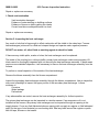
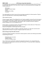
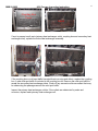
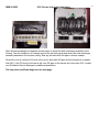
DEALER SERVICE BULLETIN
Number: DSB 09-0022
Date: 4/809
Supersedes: DSB 07-0049
Title: 90% Furnace Heat Exchanger
Inspection Procedure
PRODUCT CATEGORY:
90% furnaces
MODELS AFFECTED:
320A, 321A, 340A, 340M, 345M, 350A, 350M, 351D, 352A, 352M, 355A, 355B, 355C,
355M, 398A, 398B, 399A
58SX, SXA, SXB, SXC, DX, DXA, DXC, VCA, VUA, MCA, MCB, MXA, MXB, MSA,
UVB, MVP, MVB, MVC, MTA, MTB
490A, PG9MAA, PG9MAB
SITUATION:
There are several furnace heat exchanger inspection methodologies that have been used in the field.
Improper or inadequate furnace heat exchanger inspection techniques can result in the misdiagnosis
of a heat exchanger failure when a failure has not occurred or is not imminent.
SOLUTION:
Attached is the official Carrier / Bryant / Payne 90% Furnace Heat Exchanger Inspection Procedure.
This procedure should be utilized to properly diagnose a heat exchanger failure once preliminary
service and troubleshooting techniques indicate the heat exchanger is suspected to have failed. This
bulletin may also be used as a reference to verify the furnace is installed properly. The maintenance
items section can be used to identify any existing or future service related issues.
This inspection procedure details significant installation, set-up, and maintenance items that can
impact furnace operation, combustion characteristics, and heat exchanger performance and
reliability. In general, if an initial check of combustion performance as detailed in Section 2 of this
procedure yields CO levels in the vent of 200 ppm or less, no further examination or inspection of the
heat exchanger is required. Installation, set-up, and maintenance items should still be reviewed
and corrected to resolve any remaining furnace operational concerns. An excess air measurement
can also help in diagnosis of heat exchanger failure. The combustion check procedure included in
this document details additional steps to include this diagnostic when possible.
This bulletin also includes a 90% Furnace Heat Exchanger Inspection Certificate that must be
completed, signed by the technician, and faxed or e-mailed to Warranty Administration as part of the
heat exchanger warranty claim approval process.
Warning: Do not perform any of the servicing instructions provided in this Service Bulletin unless you are a trained and
qualified technician. Observe all precautions in the instructions, equipment tags, labels, and observe all other safety
precautions that may apply. Failure to follow this warning could result in property damage, personal injury or death.
SMB 09-0022
90% Furnace Inspection Instruction
2
This procedure and the 90% Furnace Heat Exchanger Inspection Certificate will be posted in
HVACPartners under the post-sale support service area.
Field Action:
All dealers and service contractors should use this procedure to properly
troubleshoot and inspect 90% furnace heat exchangers. .
For secondary heat exchangers with failure dates of June 15, 2009 or later, a
copy of the 90% Furnace Secondary Heat Exchanger Inspection Certificate
included in this bulletin must be faxed to Warranty Administration at (860) 9982941, or e-mailed to [email protected], as part of the claim approval
process. SMB09-0022 must appear in the e-mail subject line.
Unless otherwise notified by your distributor, replaced secondary heat
exchangers and secondary heat exchangers from replaced furnaces must be
returned to the distributor and held for potential factory audit. A copy of the 90%
Furnace Secondary Heat Exchanger Inspection Certificate must also be attached
to or held with the secondary heat exchanger part.
Section 1- Before you begin
Installing and servicing heating equipment can be hazardous due to gas and electrical components.
Only trained and qualified personnel should install, repair, or service heating equipment.
Untrained personnel can perform basic maintenance functions such as cleaning and replacing air
filters. All other operations must be performed by trained service personnel. When working on heating
equipment, observe precautions in literature, on tags, and on labels attached to or shipped with unit
and other safety precautions that may apply.
Wear safety glasses and work gloves. Have a fire extinguisher available during start-up and
adjustment procedures and service calls.
3
SMB 09-0022
90% Furnace Inspection Instruction
Follow all Local Codes. In the absence of local codes, consult the current edition of the National Fuel
Gas Code and the current edition of the National Electric Code.
Section 2- Combustion Check
Prior to performing the Combustion Check, the furnace should already have been generally inspected
and any installation, service, and/or maintenance related issues resolved. The unit should already
have been set to the correct firing rate and temperature rise. Should the furnace fail the combustion
check, this procedure will direct you to perform a more detailed examination of installation and
maintenance items which may be impacting the combustion performance.
If the furnace you are evaluating does not operate, perform a basic visual inspection of the furnace.
Discuss the situation with the homeowner. It may be necessary to perform the maintenance items in
Section 4, or perform other repairs to make the furnace operational. Performing a complete heat
exchanger removal and inspection without performing a combustion analysis may result in
unnecessary replacement of a heat exchanger. As part of the visual inspection, remove the burner
box cover and inspect the primary heat exchanger inlets for excessive soot or corrosion. If the
primary heat exchanger inlets are completely plugged with soot or corrosion, remove the heat
exchanger for inspection as explained in Section 5.
Place an “X” in the box next to each item as you perform the test.
Combustion Testing Check List
Set up furnace for CO reading
Drill a hole in the plastic PVC vent pipe approximately 12 inches from the inducer
outlet. The hole should be just large enough to allow access for the sample probe of
your combustion analyzer.
Temporarily cover this hole with duct tape
If this is a multi-stage appliance, lock the furnace in high fire.
Remove the burner box cover
Calibrate your combustion analyzer or CO meter outdoors
Measure the background CO level, the background CO level should be taken from
the room the furnace is installed in.
Is there a measurable amount of background CO?
YES
NO
IF There may be another source of CO in the home such as other gas-fired
YES appliances, automobile operation in a garage, or fireplace operation. A negative
pressure condition could exist in the home created by exhaust fans or natural draft
fireplaces. This could cause poor venting of a natural draft water heater or
automobile exhaust from an attached garage being drawn into the home or through
an un-sealed return air duct in the garage. A separate test is required to check for a
negative pressure condition in the home. Discuss this with the home owner.
IF Set the furnace to call for heat and after the blower starts and runs up to full speed,
NO observe any changes in the flame pattern in the burner box. Look for:
Floating flames
YES
NO
Flame roll out
YES
NO
Flame distortion
YES
NO
Flame discoloration (yellow, green, purple)
YES
NO
SMB 09-0022
90% Furnace Inspection Instruction
These conditions indicate a possible:
Split heat exchanger seam
Open crack
Heat exchanger deterioration/restriction
Gasket material failure
Physical separation of the connected parts
Chemical impurities in the fuel supply
Flame disturbance (i.e. significant change in flame appearance) after the blower
comes on is a good indication that further inspection of the heat exchanger is
required.
Air leaks between the primary heat exchanger cell panel and the primary heat
exchanger cell may also cause flame disturbance and should be corrected.
Check for flame impingement on the cell panel. Flame impingement does not
always indicate a heat exchanger issue. Flame impingement can be caused by
burner/orifice alignment or in some cases, air leakage around the hot surface ignitor
(silicon carbide ignitors).
Correcting these issues can correct the flame impingement issue.
If significant flame disturbance is observed after the blower comes on that cannot be
corrected by eliminating other air leaks near the burners, begin a physical inspection
of the heat exchanger. If no flame disturbance occurs, proceed to “Measure the CO
level in the vent” below.
Do you have significant flame disturbance at the burners? YES
NO
IF Go to: Section 5 - Inspecting the heat exchanger. Return to this check list following
YES inspection activities to complete procedure.
IF Go to: “Measuring the CO level in the vent”
NO
Measuring the CO level in the vent
Set the furnace to call for heat
Allow the appliance to run in high fire for a minimum of 5 minutes
Is the temperature rise at the mid-point or slightly above? YES
NO
IF Adjust blower speed to correct temperature rise
NO
IF Proceed
YES
Is Return air temperature above 60° F. and below 80° F? YES
NO
IF Allow return air to warm up above 60° F or cool down below 80° F. Verify return air
NO temperature is not being affected by outside air ducts.
IF Proceed
YES
Remove the tape over the sampling hole in vent
Insert the sample probe of your combustion analyzer into the sampling hole about
halfway into the exhaust gas stream. Seal the area around the sample probe to
prevent room air from diluting the sample
4
SMB 09-0022
90% Furnace Inspection Instruction
Take a flue gas reading and record the CO value
Is the CO level in high fire less than 200 ppm?
YES
NO
IF Go to: “Is the excess air level above 30%?”
YES
IF Complete review of installation and maintenance items (Sections 3 and 4) Identify
NO and correct any related issues. Return to this check list to complete the procedure.
Is the excess air level above 30%? If unable to
YES
NO
accurately measure excess air follow “YES” response
path and proceed.
IF No further examination or inspection of the heat exchanger is necessary. If furnace
YES operational concerns remain, a complete review of installation and maintenance
items (Sections 3 and 4) is recommended to correct remaining issues.
IF Complete review of installation and maintenance items (Sections 3 and 4). Identify
NO and correct any related issues. Return to this check list to complete the procedure.
After completing review of installation and maintenance items and correcting related
issues, re-test CO level in furnace
Operate the furnace for 10 minutes before re-test
Is the CO level in high fire less than 200 ppm?
YES
NO
IF Go to: Is the excess air above 30%?
YES
IF Go to: Section 5 - Inspecting the Heat Exchanger. Return to this check list following
NO inspection activities to complete procedure.
Is the excess air level is above 30%? If unable to
YES
NO
accurately measure excess air follow “YES” response
path and proceed..
IF No further action is necessary.
YES
IF Go to: Sections 5 - Inspecting the Heat Exchanger. Return to this check list
NO following inspection activities to complete procedure.
After adjustments and tests are made, perform the following:
Turn the gas and electric supplies to the furnace off
Remove the CO meter
Seal the hole in the vent pipe with RTV G.E. 162, G.E. RTV 6702 or Dow-Corning
RTV 738.
Install a clamp around the vent pipe
Remove any thermostat jumpers
Configure the control board for the correct type of thermostat used
Install all doors, covers and access panels removed
Turn the gas and electric supplies to the furnace on
Run furnace through one complete heating cycle
Section 3-Verify Equipment is Installed Correctly
The checklist below should be used to help identify installation issues that can result in a higher than
normal CO reading in the vent.
5
SMB 09-0022
90% Furnace Inspection Instruction
Place an “X” in the box next to each item as you inspect the system.
Equipment Correctly Installed Check List
Venting
Proper termination location per installation instructions
Termination Kit per installation instructions
Intake and exhaust terminations not reversed
Combustion-air pipe length per installation instructions
Combustion- air pipe elbow quantity 6 or less per installation instructions
Vent pipe length per installation instructions
Vent pipe elbow quantity 6 or less per installation instructions
Pipe diameter per installation instructions
Pipe sloped to furnace per installation instructions
Pipe supported properly, without sags.
Pipe insulated over ceilings per installation instructions
Pipe insulated where exposed to low-ambient conditions per installation instructions
Combustion air disk usage
NOTE: Most applications require both combustion air disks be installed but larger input
furnaces or higher altitudes may only require one combustion air disk or no disk at all.
Check the installation instructions to verify combustion air disk requirements per the
installation.
Condensate Drain
Furnace pitched forward per installation instructions. Pitch furnace forward ¼” to ½”
Internal tubing connections free of kinks and traps
External drain connections leak tight and sloped to drain
Clean condensate trap. Trapped water reduces flue gas flow and excess air.
Condensate trap primed before start-up
Heat tape installed in areas where condensate exposed to freezing conditions.
Pressure Switch Hoses
Not kinked, pinched and connected
Collector box and intake air box ports clean
Propane Conversions
Correct orifices installed
Low gas pressure switch installed
Diverter plate Installed (2 stage models)
Note: gas valve conversion/adjustment can be checked during start-up
See Propane Conversion checklist included in this section.
Start-Up
Correct size orifice installed?
Refer to installation instructions or conversion rating plate (propane models)
Orifice(s) not stripped or mis-aligned?
Orifices free of debris?
Burner clean and free of debris?
Flame retainers not corroded or distorted?
Manifold gas pressure (input rate) set within 2 percent of value as shown on rating
plate? Adjust manifold pressure according to installation instructions or conversion
rating plate (propane models). Clock meter to verify firing rate (natural gas only)
6
SMB 09-0022
90% Furnace Inspection Instruction
Temperature rise adjusted to mid-range per installation instructions
Return air temperature maintained between 60° F (min) and 80° F (max)? Check for
excess amounts of outside air. Check furnace for correct heating blower speed. Allow
building temperature to increase above 60 degrees.
Thermostat Set-up
Anticipator setting adjusted or
Electronic thermostat cycle rate (3-4 cycles per Hr.) selected
Safety Controls Check Operation-(Can be performed after Combustion Check)
Primary limit checked for proper operation
Pressure switch checked for proper operation
Accessories
Hum_ _ LFP fan powered humidifier requires an isolation relay
Outside ventilation air damper adjusted to insure return air stays within specified limits.
7
Propane Conversion - check list for propane units only
Use this check list to verify correct propane conversion and furnace operation on propane. Consult
Propane Gas Conversion Instructions for the complete step by step procedure to convert the furnace,
or for model specific requirements.
Place an “X” in the box next to each item as you inspect each item.
Propane Conversion Check List
Correct main burner orifices installed per Propane Installation Instructions
or Conversion Kit Rating Plate
Correct air shutter position (selected models only)
Diverter plate installed (two stage and variable speed models only)
Correct gas valve conversion – regulator springs and/or pre-adjust gas
valve
Low Gas Pressure Switch (LGPS) installed
Inlet gas pressure between 11-in. wc and 13.6-in wc
Correct inducer pressure switch wiring to accommodate LGPS
Check furnace operation and make necessary adjustments
Correct gas input rate (Note: the gas-input rate for propane is the same as
for natural gas. See furnace rating plate for input rate.)
Check manifold orifices for gas leaks when main burners ignite
Check Low Gas Pressure Switch (LGPS) operation
a) Switch opens at not less than 6.5 in. w.c. and closes at not
greater than 10.2 in. w.c.
b) The Switch prevents operation when the propane tank level is low,
which can result in gas with a high concentration of impurities,
and residues that have settled to the bottom of the tank.
Operation under these conditions can cause harm to the heat
exchanger system.
Check for appropriate propane conversion labeling
a) Conversion Responsibility Label applied to blower access door of
furnace.
SMB 09-0022
90% Furnace Inspection Instruction
b) Conversion Rating Plate Label
c) Gas Control Conversion Label to gas valve
Check for correct normal operation sequence of the ignition system as
described in furnace Installation, Start-Up, and Operating Instructions
8
Section 4-Maintenance Items
Important! Refer to the Service and Maintenance Instructions for the furnace model you are servicing.
The steps outlined in this section are general steps used for servicing a 90% condensing furnace.
Follow the specific steps detailed in the Service and Maintenance Instructions.
The maintenance items below should be used to identify areas of the installation that if are not done
or if done improperly, can result in a higher than normal CO reading in the vent.
A. Cleaning and/or Replacing Air Filter
NOTE: If the filter has an airflow direction arrow, the arrow must point toward the blower.
The air filter may be a disposable type, washable type or electronic air cleaner.
The filter may be located in a cabinet external to the furnace or located in the blower compartment.
Depending on the furnace size or orientation, multiple filters may be used.
As an alternative to locating the filter at the furnace, return air filter grills may be used. There may be
multiple filter grills, each with a filter.
Determine the type of filter used and either replace or clean the filter, depending on the requirements
of the filter or air cleaner manufacturer.
B. Blower Motor and Wheel Maintenance
The inducer and blower motors are pre--lubricated and require no additional lubrication. These
motors can be identified by the absence of oil ports on each end of the motor.
SMB 09-0022
90% Furnace Inspection Instruction
To clean the blower assembly:
Disconnect power from furnace
Remove blower access panel
Disconnect blower motor wiring from furnace control board
Remove the control box from the furnace and set aside
Note: Before you begin the next step, the condensate trap and tubing will have water in
it. Use caution to avoid spilling water on electrical components
If the condensate trap is installed through the blower deck, remove the condensate trap
Remove the blower assembly from the furnace
Vacuum any loose dust from the wheel, motor and housing
If necessary, disassemble the blower assembly and clean each component separately.
Re-assemble blower assembly
Install the blower assembly in the furnace
Note: If condensate trap was removed, clean the trap before installing in the blower
deck. To clean condensate trap, flush thoroughly with warm water and shake dry.
Re-install condensate trap in blower deck and re-connect all tubing and hoses (if necessary)
Reconnect any wiring removed as part of the removal process
Re-install control box in furnace
Inspect all wiring and components for loose or missing wires
Re-install blower access panel
C. Cleaning burners
To clean the burners, it will be necessary to remove the burner box. Removing the burner box will
allow for inspection of the primary heat exchanger inlets in the next step. It is highly recommended
that a new burner box gasket be installed when re-installing the burner box.
Turn the gas supply off at the external shut-off
Disconnect the gas line from the gas valve. Use a back-up wrench on gas valve to prevent
twisting or rotating the manifold in the burner box
Disconnect the combustion air pipe from the air intake box
Disconnect pressure switch hose from combustion air intake box
Remove wires from the roll-out switch
Remove wires from hot surface ignitor
Remove wire from flame sensor
Remove two screws attaching top filler panel and rotate upwards to gain access to screws
attaching burner box to cell panel
Remove the remaining screws from the burner box
Remove the burner box from the furnace
Remove the burner box cover from burner box
Remove the following items from the burner box:
ignitor and bracket
manifold
burners
flame sensor
combustion air intake box
9
SMB 09-0022
90% Furnace Inspection Instruction
10
Remove and clean the flame sensor with fine steel wool
Blow out any dust, lint or corrosion products in the burners. If the burners are rinsed out with
hot water, they should be thoroughly dried before installing in the burner box
Check the flame retainers for distortion, corrosion products, damage, or blockage from
corrosion
If corrosion cannot be adequately removed by cleaning, replace burners.
Verify the cross-over on each burner is not obstructed or deformed
Clean combustion air intake box of debris
Verify:
Combustion air disk(s) installed
Diverter Plate installed (required for all multi-stage propane installation)
Re-install the following items in the burner box:
flame sensor
burners
manifold
ignitor
burner box cover
Note: If the ignitor is installed through the bottom of the burner box, ensure that there is not a gap
between the ceramic of the ignitor and the ignitor gasket. A gap in this area can cause light –off
issues or burner pulsations
Verify the following:
Nat/Prop shutter in burner box in correct position (varies with model-refer to conversion
kit instructions)
Orifices are inserted in each burner retainer ring and the injection orifice is free of debris
and has no burrs
Manifold grommet is not binding on the burner box
Ignitor wire (varies with model) is routed through the notch in the manifold grommet
Verify the ignitor has the proper dimensions to the burner as shown in the installation
instructions
NOTE: Do Not Install the burner box at this time.
D. Cleaning the Primary Heat Exchanger-through burner inlet openings
If the heat exchangers get an accumulation of light dirt or dust on the inside, they may be cleaned by
the following procedure:
NOTE: If the heat exchangers get a heavy accumulation of soot and carbon, both the primary and
secondary heat exchangers should be replaced rather than trying to clean them thoroughly. A build-up of soot and carbon indicates that a problem exists which needs to be corrected, such as:
Improper adjustment of manifold pressure
Insufficient or poor quality combustion air
Improper venting or vent termination
Fuel supply containing chemical impurities or residue
Incorrect size, damaged or obstructed manifold orifice(s),
SMB 09-0022
90% Furnace Inspection Instruction
Restricted heat exchanger (primary or secondary)
11
Action must be taken to correct these problems
Clean heat exchanger openings with a vacuum and a soft brush. Check the screws where the primary
heat exchanger attaches to the cell panel. Are all the screws installed? Is the cell panel rusted
through? Can you see any visible gaps or cracks in the heat exchanger?
NOTE: After cleaning, inspect the heat exchangers to ensure they are free of all foreign objects that
may restrict flow of combustion products.
E. Clean the Secondary Heat Exchangers-through the collector box opening
NOTE: The inlets of the secondary heat exchangers CANNOT be serviced or inspected through the
collector box opening. A small number of bottom outlet openings can be inspected by removing the
inducer assembly.
To flush the collector box and drainage system:
Disconnect:
Inducer motor
Pressure switch wires or connectors
Pressure switch tubes
Vent pipe from inducer housing outlet
Drain tube from inducer housing
NOTE: Ensure the drain tube disconnected from the inducer housing is higher than the collector box
opening or water will flow out of tube.
Remove inducer assembly by removing 4 bolts attaching inducer assembly to cell panel.
Flush inside of collector box with water until discharge from condensate trap is clean and runs freely.
Inspect inside area of collector box for any pieces of foreign materials and remove them if present.
Re-install inducer and components in reverse order
Tighten the vent coupling clamp screw(s) to ≥15 in.--lb of torque.
SMB 09-0022
90% Furnace Inspection Instruction
12
F. Re-install the burner box
Note: The burner box should be fully assembled and ready to attach to the furnace cell inlet panel
Install a new burner box gasket on the burner box Use small dabs of RTV to hold the gasket in place.
Attach the burner box to the furnace cell inlet panel
Lower the furnace top panel, re-install screws
Install the following items:
Connect the gas line to the gas valve-Use a back-up wrench on gas valve to prevent twisting
or rotating the manifold in the burner box
Install the combustion air intake box
Connect the combustion air pipe from the air intake box
Connect pressure switch hose to combustion air intake box
Connect wires to the roll-out switch
Connect wires to hot surface ignitor
Connect wire to flame sensor
Turn on gas supply to the furnace Leak test with soap bubbles, commercially available leak detection
fluid or electronic leak detector.
G. Checking electrical connections
Look for:
Loose wires or connection
Loose screw terminals
Corroded connector pins or sockets
Pinched wires
Insulation nicked/missing
Burnt or discolored wires
Evidence of water damage/staining on controls or other surfaces
Mis-wired accessories
Repair or replace as necessary
H. Check all tubing
Look for:
Loose or broken clamps
Cracks or broken hoses-check all hoses even those that are capped and not used in some
positions.
Pinched hoses
Hard or brittle hoses or tubing
Evidence of water damage/staining on controls or other surfaces
Inverted “trap” in collector box drain tube (hose not laying flat)
Condensate drain system plugged
SMB 09-0022
90% Furnace Inspection Instruction
13
Repair or replace as necessary
I. Check vent termination
Vent termination damaged
Evidence of water staining on building surfaces
Evidence of leaves or debris getting into intake
Correct level above anticipated snow/ ice level
Repair or replace as necessary
Section 5- Inspecting the heat exchanger
Any crack or hole that is big enough to affect combustion will be visible to the naked eye. Furnace
heat exchangers joints are of a rolled and crimped design and operate under negative pressure.
DO NOT use water, oil, other fluids or smoking agents to check for leaks.
If there are any visible splits, cracks or holes, the heat exchanger must be replaced.
The inside of the coupling box, cold spot baffle, primary heat exchanger outlets and secondary HX
inlets cannot be thoroughly inspected with out removing the heat exchanger assembly. If these areas
require a more detailed inspection, it will necessary to remove the heat exchanger assembly from the
furnace.
To perform a visual inspection of the outside of the heat exchanger:
Remove the blower assembly from the blower compartment.
Inspect the secondary heat exchanger assembly through the blower compartment. Use an inspection
mirror and a flashlight to inspect the upper portion of the secondary heat exchanger. Is there
evidence of:
Corrosion
Water leakage
Perforations
If any abnormalities are noted, remove the heat exchanger assembly for further inspection.
The primary heat exchanger can be inspected in a similar manner. If an evaporator coil is not
installed on the furnace, the primary heat exchanger can be inspected through an opening in the
supply plenum. Cover any field-fabricated plenum opening with a supply air register or field fabricated
patch for the type of duct material you are working with. Seal any leaks around the register or patch
with foil tape, silicone or duct sealer.
14
SMB 09-0022
90% Furnace Inspection Instruction
If an evaporator coil is installed and the delta plate on the coil cannot be removed, drill a 7/8” hole in
the sheet metal delta plate. Use a bore scope to inspect the individual primary heat exchanger cells.
Is there evidence of:
Split seams
Improperly crimped seams
Cracks
Perforations or pitting
Corrosion
If any abnormalities are noted, remove the heat exchanger assembly for further inspection. Plug the
hole in the delta plate with a commercially available metal plug.
Other inspection options:
If there is enough “swing” in the refrigerant line set, it may be possible to remove the coil and suspend
the coil outside of the furnace. However, there is a risk that the refrigerant lines could kink and have
to be repaired. It is recommended that if this method is used, 2 people should work together to
prevent damage to the coil and refrigerant line set.
The last option is to pump the majority of the refrigerant charge in to the outdoor unit. Then recover
the remaining refrigerant charge from the system.
Remove the evaporator coil and inspect the heat exchanger.
After the inspection or repair is complete, re-install the evaporator coil. Be sure to use the correct
replacement filter drier(s) for the type of refrigerant used in the outdoor unit.
Heat exchanger inspection after removal
If the heat exchanger assembly is removed for further inspection, check for the following items before
disassembling the furnace:
Perforation due to corrosion
Fatigue cracking
Split heat exchanger seams
If any of these items are identified, replace the appropriate component. If no external defects are
found, remove the coupling box cover at the rear of the furnace. The cold spot baffle is underneath
the coupling box cover.
SMB 09-0022
90% Furnace Inspection Instruction
15
Coupling Box
Cover
Failed
If soot is present on all parts (primary heat exchanger outlet, coupling box and secondary heat
exchanger inlet), replace the entire heat exchanger assembly.
Failed
Failed
If the coupling box or cold spot baffle has significant corrosion and debris, replace the coupling
box. A new cold spot baffle is included in the coupling box kit. Remove the cold spot baffle to
reveal the secondary heat exchanger inlets. Clean off any excessive silicone sealant that may
be obstructing the passages around the cold spot baffle.
Inspect the primary heat exchanger outlets. If the outlets are obstructed by scale and
corrosion, replace each primary heat exchanger cell.
SMB 09-0022
90% Furnace Inspection Instruction
Not a Failure
16
Failed
Inspect the inlets of the secondary heat exchanger. If the inlets are significantly obstructed by
corrosion or there is significant corrosion and delamination of the polypropylene laminate,
replace the secondary heat exchanger.
Not a failure
Failed
If the secondary heat exchanger inlets are partially obstructed by corrosion or excessive
silicone sealant, carefully remove the corrosion or excess sealant from the secondary heat
exchanger inlets.
SMB 09-0022
90% Furnace Inspection Instruction
Not a failure
Not a failure
After the heat exchanger is inspected and serviced, re-install the heat exchanger assembly in the
furnace. Test the furnace for air leakage around the cell inlet panel area where the heat exchanger
assembly attaches to the furnace casing. Seal any air leaks with foil tape or silicone sealant.
Re-test the unit to verify the CO level in the vent is less than 200 ppm and the excess air is greater
than 30%. If the CO level in the vent is still over 200 ppm or the excess air is less than 30%, contact
your Distributor Service Manager for additional assistance.
The inspection certificate begins on the next page.
17
18
SMB 09-0022
90% Furnace Inspection Instruction
90% Furnace Secondary Heat Exchanger Inspection Certificate
Fax to Warranty Administration at (860) 998-2941 or e-mail to [email protected] with
SMB09-0022 in subject line. A copy of this certificate must also be attached to or held with the part.
**SCA(s)
**Customer Name
**Customer Address
**Customer Phone #
**Model Number
**Serial Number
Combustion Test Checklist
ppm
**CO reading – Required if
furnace is operational
%
Excess air level
Installation Checklist – check all areas examined per SMB09-0022
Venting
Condensate Drain
Pressure Switch Hoses
Start-up
Propane Conversion
Thermostat Set Up
Safety Control Check
Accessories
Propane Conversion
Maintenance Items – check all items cleaned or examined per SMB09-0022
Air Filter(s)
Blower Motor/Wheel
Burners/Igniter
Primary Heat
Secondary Heat
Electrical Connections
Exchanger
Exchanger
Other Tubing/Hoses
After installation and maintenance items corrected - Combustion retest
ppm
CO reading (2nd ) test
Excess air level (2nd) test
Visual Inspection of Secondary Heat Exchanger
**Observations from visual inspection of heat exchanger
%
**If furnace is replaced provide replacement model and serial number
**Model Number
**Serial Number
**Dealer Name/ Dealer Number
**Technician Name (Print)
**Technician Signature
I certify that the secondary heat exchanger in this unit failed or
that failure was deemed imminent based on observations
documented in this inspection certificate.
** Denotes Required Field