1
Installation and Operation Manual
MiRIC-E1, MiRIC-T1
Miniature Fast Ethernet to
E1/T1 Remote Bridge
Version 1.5
MiRIC-E1, MiRIC-T1
Miniature Fast Ethernet to E1/T1 Remote Bridge
Version 1.5
Installation and Operation Manual
Notice
This manual contains information that is proprietary to RAD Data Communications Ltd. ("RAD"). No
part of this publication may be reproduced in any form whatsoever without prior written approval by
RAD Data Communications.
Right, title and interest, all information, copyrights, patents, know-how, trade secrets and other
intellectual property or other proprietary rights relating to this manual and to the MiRIC-E1, MiRIC-T1
and any software components contained therein are proprietary products of RAD protected under
international copyright law and shall be and remain solely with RAD.
MiRIC-E1, MiRIC-T1 is a registered trademark of RAD. No right, license, or interest to such trademark
is granted hereunder, and you agree that no such right, license, or interest shall be asserted by you
with respect to such trademark.
You shall not copy, reverse compile or reverse assemble all or any portion of the Manual or the MiRICE1, MiRIC-T1. You are prohibited from, and shall not, directly or indirectly, develop, market,
distribute, license, or sell any product that supports substantially similar functionality as the MiRIC-E1,
MiRIC-T1, based on or derived in any way from the MiRIC-E1, MiRIC-T1. Your undertaking in this
paragraph shall survive the termination of this Agreement.
This Agreement is effective upon your opening of the MiRIC-E1, MiRIC-T1 package and shall continue
until terminated. RAD may terminate this Agreement upon the breach by you of any term hereof.
Upon such termination by RAD, you agree to return to RAD the MiRIC-E1, MiRIC-T1 and all copies
and portions thereof.
For further information contact RAD at the address below or contact your local distributor.
International Headquarters
RAD Data Communications Ltd.
North America Headquarters
RAD Data Communications Inc.
24 Raoul Wallenberg St.
Tel Aviv 69719 Israel
Tel: 972-3-6458181
Fax: 972-3-6498250
E-mail: [email protected]
900 Corporate Drive
Mahwah, NJ 07430 USA
Tel: (201) 529-1100, Toll free: 1-800-444-7234
Fax: (201) 529-5777
E-mail: [email protected]
© 1991–2006 RAD Data Communications Ltd.
Publication No. 412-200-08/06
Limited Warranty
RAD warrants to DISTRIBUTOR that the hardware in the MiRIC-E1, MiRIC-T1 to be delivered
hereunder shall be free of defects in material and workmanship under normal use and service for a
period of twelve (12) months following the date of shipment to DISTRIBUTOR.
If, during the warranty period, any component part of the equipment becomes defective by reason of
material or workmanship, and DISTRIBUTOR immediately notifies RAD of such defect, RAD shall have
the option to choose the appropriate corrective action: a) supply a replacement part, or b) request
return of equipment to its plant for repair, or c) perform necessary repair at the equipment's location.
In the event that RAD requests the return of equipment, each party shall pay one-way shipping costs.
RAD shall be released from all obligations under its warranty in the event that the equipment has been
subjected to misuse, neglect, accident or improper installation, or if repairs or modifications were
made by persons other than RAD's own authorized service personnel, unless such repairs by others
were made with the written consent of RAD.
The above warranty is in lieu of all other warranties, expressed or implied. There are no warranties
which extend beyond the face hereof, including, but not limited to, warranties of merchantability and
fitness for a particular purpose, and in no event shall RAD be liable for consequential damages.
RAD shall not be liable to any person for any special or indirect damages, including, but not limited to,
lost profits from any cause whatsoever arising from or in any way connected with the manufacture,
sale, handling, repair, maintenance or use of the MiRIC-E1, MiRIC-T1, and in no event shall RAD's
liability exceed the purchase price of the MiRIC-E1, MiRIC-T1.
DISTRIBUTOR shall be responsible to its customers for any and all warranties which it makes relating
to MiRIC-E1, MiRIC-T1 and for ensuring that replacements and other adjustments required in
connection with the said warranties are satisfactory.
Software components in the MiRIC-E1, MiRIC-T1 are provided "as is" and without warranty of any
kind. RAD disclaims all warranties including the implied warranties of merchantability and fitness for a
particular purpose. RAD shall not be liable for any loss of use, interruption of business or indirect,
special, incidental or consequential damages of any kind. In spite of the above RAD shall do its best to
provide error-free software products and shall offer free Software updates during the warranty period
under this Agreement.
RAD's cumulative liability to you or any other party for any loss or damages resulting from any claims,
demands, or actions arising out of or relating to this Agreement and the MiRIC-E1, MiRIC-T1 shall not
exceed the sum paid to RAD for the purchase of the MiRIC-E1, MiRIC-T1. In no event shall RAD be
liable for any indirect, incidental, consequential, special, or exemplary damages or lost profits, even if
RAD has been advised of the possibility of such damages.
This Agreement shall be construed and governed in accordance with the laws of the State of Israel.
Declaration of Conformity
Manufacturer's Name:
RAD Data Communications Ltd.
Manufacturer's Address:
24 Raoul Wallenberg St.
Tel Aviv 69719
Israel
declares that the product:
MiRIC
Product Name:
Conforms to the following standard(s) or other normative document(s):
EMC:
Safety:
EN 55022: 1998
Information technology equipment – Radio disturbance
characteristics – Limits and methods of measurement.
EN 55024: 1998
Information technology equipment – Immunity characteristics
– Limits and methods of measurement.
EN 60950-1: 2001
Information technology equipment – Safety – General
requirements.
Supplementary Information:
The product herewith complies with the requirements of the EMC Directive 89/336/EEC, the Low
Voltage Directive 73/23/EEC and the R&TTE Directive 99/5/EC for wired equipment. The product was
tested in a typical configuration.
Tel Aviv, 25 April 2005
Haim Karshen
VP Quality
European Contact: RAD Data Communications GmbH, Otto-Hahn-Str. 28-30,
85521 Ottobrunn-Riemerling, Germany
Contents
Chapter 1. Introduction
1.1 Overview..................................................................................................................... 1-1
Product Options ................................................................................................................... 1-1
Applications.......................................................................................................................... 1-1
Features................................................................................................................................ 1-2
1.2 Physical Description..................................................................................................... 1-2
1.3 Technical Specifications............................................................................................... 1-3
Chapter 2. Installation and Setup
2.1
2.2
2.3
2.4
2.5
2.6
Introduction................................................................................................................. 2-1
Site Requirements and Prerequisites ............................................................................ 2-1
Package Contents ........................................................................................................ 2-1
Configuring MiRIC-E1, MiRIC-T1 ................................................................................. 2-1
Inserting the MiRIC-E1, MiRIC-T1................................................................................ 2-2
Connecting the Interface Cable.................................................................................... 2-3
Chapter 3. Operation
3.1 Indicators..................................................................................................................... 3-1
3.2 Configuration Alternatives............................................................................................ 3-1
DIP switch ............................................................................................................................ 3-1
Software control via I2C Interface .......................................................................................... 3-1
Chapter 4. API Reference
4.1
4.2
4.3
4.4
Introduction................................................................................................................. 4-1
SFP MSA Standard ....................................................................................................... 4-1
Management Message Format ..................................................................................... 4-2
Management Procedure .............................................................................................. 4-3
Read Message....................................................................................................................... 4-3
Write Message ...................................................................................................................... 4-4
4.5 Parameters .................................................................................................................. 4-4
General Parameters .............................................................................................................. 4-4
Status Parameters.................................................................................................................. 4-5
Configuration Parameters...................................................................................................... 4-5
Statistic Parameters ............................................................................................................... 4-7
Diagnostic Parameters........................................................................................................... 4-8
4.6 Typical Examples ......................................................................................................... 4-8
Reading LCVCR 1 statistic for T1 ........................................................................................... 4-8
Configuring LLB .................................................................................................................... 4-8
4.7 SFP Identification Fields ............................................................................................... 4-9
MiRIC-E1, MiRIC-T1 Ver. 1.5
i
Table of Contents
ii
Installation and Operation Manual
MiRIC-E1, MiRIC-T1 Ver. 1.5
Chapter 1
Introduction
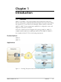
1.1
Overview
MiRIC-E1 and MiRIC-T1 are patent-pending remote bridges that forward Fast
Ethernet LAN packets to TDM-based WAN at full duplex wire-speed, fully utilizing
the expensive E1/T1 rate TDM circuit bandwidth, whether framed or unframed.
MiRIC-E1, MiRIC-T1 have management capabilities for configuration, status, and
diagnostics via the SFP I2C interface.
Housed in a Small Form Factor Pluggable (SFP) package, MiRIC-E1, MiRIC-T1
complies with the Multi-Source Agreement (MSA) for SFPs, MiRIC-E1, MiRIC-T1
also complies with the E1/T1 line and framing requirements.
Product Options
MiRIC-E1
MiRIC-T1
Applications
Figure 1-1. Providing Transparent LAN Services over Leased Lines
MiRIC-E1, MiRIC-T1 Ver. 1.5
Overview
1-1
Chapter 1 Introduction
Installation and Operation Manual
Features
•
Framed or unframed E1 or T1 links
•
Basic management for configuration, status and diagnostics.
•
Hot-insertion SFP footprint, MSA compliant
•
Full duplex wire-speed packet forwarding
•
Configurable Tx clock source and data format
Internal or Rx clock
Framed or Unframed
•
Visual fault indication:
Loss of E1 or T1 signal
Loss of Ethernet link
•
Support flow control
•
Product identification support
•
Easy release mechanism
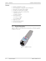
1.2
Physical Description
MiRIC-E1, MiRIC-T1 are SFP devices that are inserted into a SFP MSA compatible
receptacle in a host unit.
Figure 1-2. MiRIC-E1 3D View
1-2
Physical Description
MiRIC-E1, MiRIC-T1 Ver. 1.5
Installation and Operation Manual
Chapter 1 Introduction
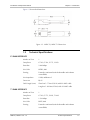
Figure 1-3 shows the dimensions.
Figure 1-3. MiRIC-E1, MiRIC-T1 Dimensions
1.3
Technical Specifications
E1 WAN INTERFACE
Number of Ports
1
Compliance
G.703, G.704, G.775, G.823
Data Rate
2.048 Mbps
Line Code
HDB3, AMI
Framing
Framed or unframed (switch-selectable and software
controllable)
Line Impedance
120Ω, unbalanced
Connector
RJ-45
Cable Length (max)
Short haul – 770m (2530 ft) with 22 AWG cable
Long haul – 2664m (8740 ft) with 22 AWG cable
T1 WAN INTERFACE
Number of Ports
1
Compliance
G.703, G.775, G.823, T1.403
Data Rate
1.544 Mbps
Line Code
B8ZS, AMI
Framing
Framed or unframed (switch-selectable and software
controllable)
MiRIC-E1, MiRIC-T1 Ver. 1.5
Technical Specifications
1-3
Chapter 1 Introduction
Installation and Operation Manual
Line Impedance
100Ω, unbalanced
Connector
RJ-45
Cable Length (max)
Short haul – 1192m (3910 ft) with 22 AWG cable
Long haul – 2874m (9430 ft) with 22 AWG cable
LAN INTERFACE
Type
Fast Ethernet SFP port, MSA compliant
Compliance
IEEE 802.3, SFP MSA
Edge Connector
SFP transceiver, MSA compliant
WAN PROTOCOL
Type
HDLC-like framing (native HDLC compatible with RAD
products)
LED Indicators
LINK (green) – Ethernet link status
GENERAL
LOS (red) – E1/T1 loss of signal
1-4
Regulatory
Compliance
Safety: IEC-60950-1
Transmit Clock
Internal or receive (switch-selectable and software
controllable)
Power
3.3V, up to 300 mA
Thermal
Management
Power dissipation less than 1W
Dimensions
Height:
Width:
Depth:
Weight
Technical Specifications
EMI: EN55022 (Class B), EN55024, FCC-15
13.8 mm (0.54 in)
15.8 mm (0.62in)
75.9 mm (2.99 in)
30.0 g (1.0 oz)
MiRIC-E1, MiRIC-T1 Ver. 1.5
Chapter 2
Installation and Setup
2.1
Introduction
Housed in a Small Form Factor Pluggable (SFP) package, MiRIC-E1 and MiRIC-T1
comply with the Multi-Source Agreement (MSA) and can be inserted into any MSA
compatible host unit.
MiRIC-E1, MiRIC-T1 are autonomous plug-and-play hot-insertion modules. The
device can be configured manually via DIP switches or via an I2C Interface. For
more details, see Chapter 4.
2.2
Site Requirements and Prerequisites
The ambient operating temperature should be –40°C to 70°C (–40°F to 158°F), at
a relative humidity of up to 90%, non-condensing.
2.3
Package Contents
The MiRIC-E1, MiRIC-T1 package includes the following items:
•
Up to four MiRIC-E1 or MiRIC-T1 units
•
Technical documentation CD.
2.4
Configuring MiRIC-E1, MiRIC-T1
MiRIC-E1, MiRIC-T1 framing mode and transmit clock source are configured
manually via the DIP switch on the underside of the device.
Note
The DIP switch configuration may be overridden by software commands. The latest
configuration is stored in a non-volatile memory, which is retained even if the MiRIC
is removed from the host, however, if the DIP switch state is then changed, this
overrides the software configuration and the DIP switch setting becomes the latest
configuration.
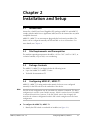
To configure the MiRIC-E1, MiRIC-T1
1. Identify the DIP switch on underside of module (see Figure 2-1).
MiRIC-E1, MiRIC-T1 Ver. 1.5
Configuring MiRIC-E1, MiRIC-T1
2-1
RCV
INT
Un-FRM
Installation and Operation Manual
FRM
Chapter 2 Installation and Setup
Figure 2-1. DIP Switch Location
2. Set DIP switches according to Table 2-1.
Table 2-1. DIP Switch Settings
Switch Identity
Possible Settings
Factory Setting
Framing
FRM – Framed
T1 – Un-FRM
Un-FRM – Unframed
E1 – Un-FRM
Transmit clock
INT – Internal
RCV – Receive
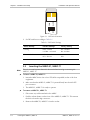
2.5
Note
RCV
Inserting the MiRIC-E1, MiRIC-T1
There is no need to power down the host unit when inserting or extracting the
MiRIC-E1, MiRIC-T1.
To insert a MiRIC-E1, MiRIC-T1
1. Insert the MiRIC device into a free SFP (MSA-compatible) socket of the host
equipment.
2. Make sure that the MiRIC-E1, MiRIC-T1 is pressed firmly into the MSA SFP
port connector.
3. The MiRIC-E1, MiRIC-T1 is ready to operate.
To remove a MiRIC-E1, MiRIC-T1
1. Disconnect any cables attached to the MiRIC.
1. Push the release button on the front of the MiRIC-E1, MiRIC-T1. This extracts
the device from the edge connector.
2. Remove the MiRIC-E1, MiRIC-T1 from the socket.
2-2
Inserting the MiRIC-E1, MiRIC-T1
MiRIC-E1, MiRIC-T1 Ver. 1.5
Installation and Operation Manual
2.6
Chapter 2 Installation and Setup
Connecting the Interface Cable
To connect the interface cable
•
Use a CAT5 cable terminated in an RJ-45 to connect between MiRIC-E1,
MiRIC-T1 and the E1/T1 line.
MiRIC-E1, MiRIC-T1 Ver. 1.5
Connecting the Interface Cable
2-3
Chapter 2 Installation and Setup
2-4
Connecting the Interface Cable
Installation and Operation Manual
MiRIC-E1, MiRIC-T1 Ver. 1.5
Chapter 3
Operation
3.1
Indicators
The front panel of the MiRIC-E1, MiRIC-T1 has two status LEDs. See Table 3-1 for
details.
Table 3-1. LED Indications
Note
LED
Possible Status
LINK (green)
ON – Ethernet link is valid
OFF – No Ethernet link
LOS (red)
ON – No E1/T1 signal is detected
OFF – Valid E1/T1 signal is detected
Certain equipment may cause the LINK LED to turn on before the E1/T1 cable has
been connected. This is normal.
3.2
Configuration Alternatives
DIP switch
MiRIC-E1, MiRIC-T1 framing mode and transmit clock source can be configured
manually via the DIP switch on the underside of the device, see Chapter 2.
Software control via I2C Interface
The MiRIC-E1, MiRIC-T1 has management capabilities including configuration,
status monitoring, and diagnostics via the SFP edge connector I2C interface. See
Chapter 4 for the full instruction set and message format.
MiRIC-E1, MiRIC-T1 Ver. 1.5
Configuration Alternatives
3-1
Chapter 3 Operation
3-2
Configuration Alternatives
Installation and Operation Manual
MiRIC-E1, MiRIC-T1 Ver. 1.5
Chapter 4
API Reference
4.1
Introduction
This section describes MiRIC-E1, MiRIC-T1 management channel, management
protocol and management parameters.
The host accesses MiRIC-E1, MiRIC-T1 via the I2C channel in order to identify the
device and perform management.
Two types of messages are described:
•
I2C message – in standard I2C frame structure
•
Management message – the message structure the host sends to the MiRIC-E1,
MiRIC-T1 encapsulated in the I2C message
All address and values in this section are given in hexadecimal.
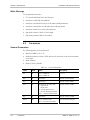
4.2
SFP MSA Standard
MiRIC-E1, MiRIC-T1 comply with the MSA standard and hence have the same I2C
mechanism. MiRIC-E1, MiRIC-T1 follow the basic parameter map as outlined by
the MSA (as based on SFF 8472). Figure 4-1 describes the mapping of page A0 as
seen by the host equipment.
MiRIC-E1, MiRIC-T1 identification parameters reside in page A0.
2 wire address 10100000 (A0h)
0
0
Serial ID Defined by
SFP MSA (96 bytes)
5F
95
Vendor Specific
(32 bytes)
127
7F
Reserved for SFP8079
(128 bytes)
255
FF
Figure 4-1. Page A0 mapping
As shown above, the second sector, addresses 0x60-0x7F are reserved for vendor
specifics. MiRIC-E1, MiRIC-T1 uses these addresses for configuration, diagnostic,
and status monitoring parameters.
MiRIC-E1, MiRIC-T1 Ver. 1.5
SFP MSA Standard
4-1
Chapter 4 API Reference
Installation and Operation Manual
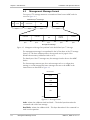
4.3
Management Message Format
Two types of I2C message structures are transferred from host to MiRIC and vice
versa see Figure 4-2.
Multi data byte I 2C Message
Start
Control
R/W
Slave address
Byte 1
Data
Byte 2
Index MSB
Byte 1
Data
Byte 3
Index LSB
Byte 2
Byte 8
R/W
Length of
Parameter
Byte 3
Byte 4
Parameter
Byte 5
Management Message
Figure 4-2. Management Message Encapsulated in the Multi-Data byte I2C Message
The management message is encapsulated in the in Data bytes of the I2C message
(bytes 3-8). The slave address points to the reserved area in page 0 of the
identification memory (addresses 0x60 to 0x7F).
The data bytes of the I2C message carry the message from the host to the MiRIC
device.
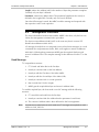
The host message structure may be a write message such as a configuration
message or a read message like status. Messages are sent to the MiRIC in the
format shown as described in Figure 4-3.
Reserved Area
128
Index
2 bytes
0x80
Read/Write
1 byte
Length of Parameter
1 byte
Data
255
0xFF
Figure 4-3. Message Format
Index: written into addresses 0x80 and 0x81 – The Index bytes determine the
command code of the host message.
Read/Write: written into address 0x82 – This byte determines if the command is a
read or write operation.
4-2
Management Message Format
MiRIC-E1, MiRIC-T1 Ver. 1.5
Installation and Operation Manual
Chapter 4 API Reference
Length: written into address 0x83 is the number of bytes the parameter comprises.
Currently only one byte is allowed.
Parameter: written into address 0x84. The parameter length must be exactly as
defined in the Length field. Currently only one byte is allowed.
Once the full message is stored, the MiRIC reads the message and responds with
the respective read or write operation.
4.4
Management Procedure
The host is the defined as the master and the MiRIC is the slave, only the host can
initiate the management communication procedure.
The host accesses addresses 0x80–0x9E, in the same way that it accesses SFP
identification addresses (0x00–0x5F).
I2C messages from the host are composed from read and write messages. In a read
command, the read parameters (Index, R/W, and Length) are stored at addresses
0x80-0x83, following these parameters MiRIC gets the required data byte and
stores it in address 0x84. The complete message is then delivered via the I2C to the
host.
Read Message
I2C encapsulation structure
1. I2C Control and Write bits in the first byte.
2. Next byte contains 0x80 (as the first address).
3. Next byte with the First byte of the Index (MSB).
4. Next byte with the Second byte of the Index (LSB).
5. Next byte contains 0x01 for a read operation.
6. Byte contains 0x01 for the Length.
7. MiRIC gets the required data byte and stores in address 0x84.
To read the required byte, the host sends a new I2C message with the following
structure:
8. I2C control bits and read bit in the first byte.
9. Next byte contains 0x84 (the address that the parameter is read from).
10. The content of address 0x84 is then delivered to the host equipment.
Note
In event two or more bytes are to be read, two I2C messages are required, to read
addresses 0x84, 0x85 etc.
MiRIC-E1, MiRIC-T1 Ver. 1.5
Management Procedure
4-3
Chapter 4 API Reference
Installation and Operation Manual
Write Message
I2C encapsulation structure:
1. I2C control and Write bits in the first byte.
2. Next byte is 0x80 (the first address).
3. Next byte contains the first byte of the Index (MSB) parameter.
4. Next byte contains the second Index byte (LSB) parameter.
5. Next byte is 0x00 for a write code operation.
6. Byte with content of 0x01 for the Length.
7. Byte with parameter data to be written.
4.5
Parameters
General Parameters
The following tasks can be performed:
•
Identify if MiRIC is E1 or T1.
•
Read the software version X.YZR, where each character in the version number
is one byte.
•
Reset software.
•
Reset to factory defaults.
Table 4-1. General Parameters
4-4
Index
R/W
Value
Description
0x1
R
0x01 = MiRIC E1
0x02 = MiRIC T1
E1 or T1
0x2
R
0x00–0xFF
Software version X.YZR
0x3
R
0x00–0x63
Software version X.YZR
0x4
R
All values are in ASCII code
A = Alpha 0x41
B = Beta 0x42
D = Development 0x44
E = End of development 0x45
NULL = Official release 0x00
Software version X.YZR
0x5
R
0x00–0x63
Software version X.YZR
0x12C
W
0x02 – software reset
0x03 – set to factory default
Reset and factory default
Parameters
MiRIC-E1, MiRIC-T1 Ver. 1.5
Installation and Operation Manual
Chapter 4 API Reference
Status Parameters
The following status parameters are available for reading:
•
Loss of Rx signal (LOS)
•
Alarm indication signal (AIS)
•
Yellow alarm (T1 only).
Table 4-2. Status Parameters
Index
R/W
Description
0x3E8
R
1= Active 0 = Inactive
Digit 0 = LOS (Loss of Rx signal)
Digit 1 = Don’t care
Digit 2 = AIS (Alarm indication signal)
Digit 3 = Yellow alarm (T1 only)
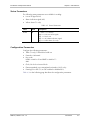
Configuration Parameters
Configure the following parameters:
•
TLB0 (T1 only), Transmit line build out
•
Framed or Unframed
•
Line code:
HDB3 or AMI for E1 and B8ZS or AMI for T1
AMI
•
Clock, Rx clock or internal clock
•
Data transmitted or not transmitted on timeslot 16 (E1 only)
•
Framing D4 or ESF (T1) or CRC enabled or disabled (E1).
Table 4-3 on the following page describes the configuration parameters.
MiRIC-E1, MiRIC-T1 Ver. 1.5
Parameters
4-5
Chapter 4 API Reference
Installation and Operation Manual
Table 4-3. Configuration Parameters
Index
R/W
Description
Default
0x514
R+W
Digit 0 – 2, TLB0 (T1 only) - Transmit line build out:
000 = 0 ft – 133 ft
001 = 133 ft – 266 ft
010 = 266 ft – 399 ft
011 = 399 ft – 533 ft
100 = 533 ft – 655 ft
101 = -7 to -5 dB
110 = -15 dB
111 Internal use only
E1: 001 un-configurable
T1: 000
Digit 3, Framed/Unframed:
0 = Unframed
1 = Framed
0 = unframed
Digit 4, Line code:
0 = HDB3 (E1) or B8ZS (T1)
1 = AMI
E1: 0 = HDB3
T1: 0 = B8ZS
0 = Rx clock
Digit 5, Tx Clock:
0 = Rx clock
1 = internal clock
0 = Data transmitted in TS16
Digit 6, Timeslot 16 (E1 only)
0 = Data transmitted in TS16
1 = No data transmitted in TS16
E1: 1 = CRC disable
T1: 1 = ESF
Digit 7, Framing (T1)/CRC (E1)
0 = D4 (T1)/CRC enable (E1)
1 = ESF (T1)/CRC disable (E1)
0x515
R+W
Rx Sensitivity
E1 mode
E1 mode
Short haul
0
-12 db
Long haul
1
-43 db
Long haul
T1 mode
0x518
R+W
1
-43 db
0
-36 db
T1 mode
Long haul
0
-36 db
Limited long haul
1
-15 db
Long haul
XXXX XXX0 Normal operation
Digit 0, Yellow Alarm:
0 = Normal operation
1 = Sends Yellow alarm.
0x531
R+W
0 = Disable
1 = Enable
0x532
R+W
1 = Enable
Fault propagation
Limited long haul
Tx Disable behavior:
1
10 = AIS
00 = NA – no impact
01 = 3 state
10 = AIS
4-6
Parameters
MiRIC-E1, MiRIC-T1 Ver. 1.5
Installation and Operation Manual
Chapter 4 API Reference
Table 4-3. Configuration Parameters (Cont.)
Index
R/W
Description
Default
0x708
R+W
0x5 =TAIS, transmit AIS
0 = Normal operation
1 = Transmits AIS.
Normal operation
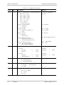
Statistic Parameters
The statistics below are updated once a second, it is the host’s responsibility to poll
the statistics and to calculate the intervals.
Two bytes are reserved for each counter.
Table 4-4. Statistic Parameters
Index
R/W
Parameter
Description
E1/T1
0x640
R
LCVCR 1
Line-Code Violation Count
E1
0x641
R
LCVCR 2
0x642
R
PCVCR 1
0x643
R
PCVCR 2
0x644
R
FOSCR 1
0x645
R
FOSCR 2
0x646
R
EBCR 1
0x647
R
EBCR 2
0x672
R
LCVCR 1
0x673
R
LCVCR 2
0x674
R
PCVCR 1
0x675
R
PCVCR 2
0x676
R
FOSCR 1
0x677
R
FOSCR 2
MiRIC-E1, MiRIC-T1 Ver. 1.5
E1
Path Code Violation Count
E1
E1
Frames Out-of-Sync Count
E1
E1
E-Bit Counter
E1
E1
Line-Code Violation Count
T1
T1
Path Code Violation Count
T1
T1
Frames Out-of-Sync Count
T1
T1
Parameters
4-7
Chapter 4 API Reference
Installation and Operation Manual
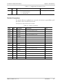
Diagnostic Parameters
The following diagnostics are available:
•
Normal operation
•
Local loopback, LLB
•
Remote loopback, RLB
•
Transmit AIS, TAIS.
Table 4-5. Diagnostic Parameters
Index
R/W
Description
Default
0x708
R+W
0x0 = Normal operation
0x1 = LLB
0x2 = RLB
0x5 =TAIS, transmit AIS
XXXX X000
Normal operation
1. Normal operation after reset
2. No time out for loops
4.6
Typical Examples
Reading LCVCR 1 statistic for T1
1. I2C Control and Write bits in the first byte
2. Next byte with content of 0x80 (as the first address).
3. Next byte with the First byte of the Index (MSB) – 0x06.
4. Next byte with the Second Index byte of the Index (LSB) – 0x72.
5. Next byte contains 0x01 for a read operation.
6. Byte with content of 0x01 for the Length (in this example the parameter
Length is one byte)
To read the required byte, the host sends a new I2C message with the following
structure:
1. I2C control bits and read bit in the first byte
2. Next byte with content of 0x84 (for the first address).
3. In response, MiRIC sends the contents of address 0x84 (message per byte) to
the host equipment.
Configuring LLB
1. I2C control and Write bits in the first byte
2. Next byte is 0x80 (the first address)
3. Next byte contains the first byte of the Index (MSB) parameter – 0x07.
4. Next byte contains the second Index byte (LSB) parameter – 0x08.
4-8
Typical Examples
MiRIC-E1, MiRIC-T1 Ver. 1.5
Installation and Operation Manual
Chapter 4 API Reference
5. Next byte is 0x00 for a write code operation.
6. Byte with content of 0x01 for the Length
7. Byte with content of 0x01 sets the LLB parameter
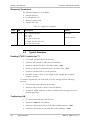
4.7
SFP Identification Fields
Table 4-6. MiRIC-E1/T1 SFP ID fields
Field name
MIRIC-E1
MIRIC-T1
1. Vendor Name
RAD data comm.
RAD data comm.
2. Vendor OUI
0
0
3. Vendor PN
MIRIC-E1
MIRIC-T1
4. Vendor Revision
1.5
1.5
5. Vendor S/N
0
0
6. Identifier
SFP
SFP
7. Ext.Identifier
04
04
8. Connector
Unknown
Unknown
9. Wavelength
0
0
10. Encoding
Unspecified
Unspecified
11. BR Nominal
0
0
12. BR Max
0
0
13. BR Min
0
0
14. Length 9/125 (km)
2
2
15. Length 9/125 (100m)
6
8
16. Length 50/125 (10m)
0
0
17. Length 62.5/125 (10m)
0
0
18. Length Copper (1m)
0
0
19. Year Data Code
0
0
20. Month Data Code
0
0
21. Day Data Code
0
0
22. VS Data Code
0
0
23. Diag Monitor Type
0
0
24. Enhanced Option
0
0
25. SFF 8472 Compliance
0
0
26. CC Base (Hex)
DS
E6
27. CC Ext (Hex)
FF
FF
28.Rate Select
NO
NO
MiRIC-E1, MiRIC-T1 Ver. 1.5
SFP Identification Fields
4-9
Chapter 4 API Reference
4-10
Installation and Operation Manual
Field name
MIRIC-E1
MIRIC-T1
29. TX Disable
YES
YES
30. TX Fault
NO
NO
31. Signal Loss Inv
NO
NO
32. Signal Loss
YES
YES
33. SONET S1
NO
NO
34. SONET S2
NO
NO
35. OC3 MM Short
NO
NO
36. OC3 SM inter
NO
NO
37. OC3 SM long
NO
NO
38. OC12 MM Short
NO
NO
39. OC12 SM inter
NO
NO
40. OC12 SM long
NO
NO
41. OC48 Short
NO
NO
42. OC48 inter
NO
NO
43. OC48 long
NO
NO
44. 1000BaseSx
NO
NO
45. 1000BaseLx
NO
NO
46. 1000BaseCx
NO
NO
47. 1000BaseT
NO
NO
48. 100BaseFX SM
NO
NO
49. 100BaseFX MM
NO
NO
50. FC Very long
NO
NO
51. FC long
NO
NO
52. FC Short
NO
NO
53. FC Inter
NO
NO
54. FC Media TW
NO
NO
55. FC Media TP
NO
NO
56. FC Media MI
NO
NO
57. FC Media TV
NO
NO
58. FC Media M6
NO
NO
59. FC Media M5
NO
NO
60. FC Media SM
NO
NO
SFP Identification Fields
MiRIC-E1, MiRIC-T1 Ver. 1.5
24 Raoul Wallenberg St., Tel Aviv 69719, Israel
Tel: +972-3-6458181, Fax: +972-3-6483331, +972-3-6498250
E-mail: [email protected], Web site: www.rad.com
Customer Response Form
RAD Data Communications would like your help in improving its product documentation.
Please complete and return this form by mail or by fax or send us an e-mail with your
comments.
Thank you for your assistance!
MiRIC-E1, MiRIC-T1
Manual Name: ______________________________________________________________
412-200-08/06
Publication Number: __________________________________________________________
Please grade the manual according to the following factors:
Installation instructions
Operating instructions
Manual organization
Illustrations
The manual as a whole
Excellent
Good
Fair
Poor
Very Poor
What did you like about the manual?
___________________________________________________________________________
___________________________________________________________________________
___________________________________________________________________________
___________________________________________________________________________
___________________________________________________________________________
Error Report
Type of Error(s)
Incompatibility with product
or Problem(s):
Difficulty in understanding text
Regulatory information (Safety, Compliance, Warnings, etc.)
Difficulty in finding needed information
Missing information
Illogical flow of information
Style (spelling, grammar, references, etc.)
Appearance
Other _________
Please list the exact page numbers with the error(s), detail the errors you found (information missing,
unclear or inadequately explained, etc.) and attach the page to your fax, if necessary.
_________________________________________________________________________________________
_________________________________________________________________________________________
_________________________________________________________________________________________
_________________________________________________________________________________________
Please add any comments or suggestions you may have.
_________________________________________________________________________________________
_________________________________________________________________________________________
_________________________________________________________________________________________
You are:
Distributor
End user
VAR
Other ________________________
Who is your distributor?
_______________________________
Your name and company: ___________________________________________________________
Job title: __________________________________________________________________________
Address: __________________________________________________________________________
Direct telephone number and extension: _______________________________________________
Fax number: ______________________________________________________________________
E-mail: _____________________________________________________________________
www.rad.com
INTERNATIONAL HEADQUARTERS:
24 Raoul Wallenberg Street, Tel Aviv 69719, Israel, Tel: 972-3-6458181
Fax: 972-3-6498250, 972-3-6474436, Email: [email protected]
NORTH AMERICA HEADQUARTERS:
900 Corporate Drive, Mahwah, N.J. 07430, Tel: (201) 529-1100
Toll Free: 1-800-444-7234, Fax: (201) 529-5777, Email: [email protected]
Publication No. 412-200-08/06