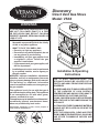
1
Discovery Direct Vent Gas Stove Model: VS38 WARNINGS If the information in these instructions are not followed exactly, a fire or explosion may result causing property damage, personal injury or loss of life. – Do not store or use gasoline or other flammable vapors and liquids in the vicinity of this or any other appliance. – WHAT TO DO IF YOU SMELL GAS • Do not try to light any appliance. • Do not touch any electrical switch; do not use any phone in your building. • Immediately call your gas supplier from a neighbor's phone. Follow the gas supplier's instructions. • If you cannot reach your gas supplier, call the fire department. – Installation and service must be performed by a qualified installer, service agency or the gas supplier. WARNING: Improper installation, adjustment, alteration, services or maintenance can cause injury or property damage. Refer to this manual. For assistance or additional information consult a qualified installer, service agency or the gas supplier. This appliance is only for use with the type of gas indicated on the rating plate. This appliance is not convertible for use with other gases, unless a certified kit is used. This appliance may be installed in an aftermarket*, permanently located, manufactured home, where not prohibited by local codes. *Aftermarket: Completion of sale, not for purpose of resale, from the manufacturer. Installation & Operating 0245 Instructions VS38 cover D U E T O H I G H T E M P E R AT U R E S , T H E APPLIANCE SHOULD BE LOCATED OUT OF TRAFFIC AND AWAY FROM FURNITURE AND DRAPERIES. CHILDREN AND ADULTS SHOULD BE ALERTED TO THE HAZARDS OF HIGH SURFACE TEMPERATURE AND SHOULD STAY AWAY TO AVOID BURNS OR CLOTHING IGNITION. YOUNG CHILDREN SHOULD BE SUPERVISED WHEN THEY ARE IN THE SAME ROOM AS THE APPLIANCE. CLOTHING OR OTHER FLAMMABLE MATERIAL SHOULD NOT BE PLACED ON OR NEAR THE APPLIANCE. Keep the room area clear and free from combustible materials, gasoline, and other flammable vapors and liquids. 203000245 8/10 Rev. 3 VS38 Direct Vent Gas Stove TABLE OF CONTENTS PLEASE READ THE INSTALLATION & OPERATING INSTRUCTIONS BEFORE USING THIS APPLIANCE. Thank you and congratulations on your purchase of a Vermont Castings gas stove. IMPORTANT: Read all instructions and warnings carefully before starting installation. Failure to follow these instructions may result in a possible fire hazard and will void the warranty. Important Safety Information...................................... 3 Code Approval.............................................................. 4 Product Features.......................................................... 5 Product Specifications............................................. 5 High Elevations........................................................ 5 Gas Pressures......................................................... 5 Gas Specifications & Orifice Size............................ 5 Operating Instructions............................................... 27 What To Do If You Smell Gas................................. 27 Lighting Pilot for the First Time.............................. 27 Lighting Pilot.......................................................... 28 Lighting Burner....................................................... 29 To Turn Off Gas...................................................... 29 Pre-Installation Information Stove Location......................................................... 7 Cleaning & Maintenance............................................ 30 Venting System...................................................... 30 Cleaning Glass....................................................... 30 Pilot and Burner Flames........................................ 30 Firebox Cleaning.................................................... 30 Clearances.................................................................... 8 Air Shutter Adjustment.............................................. 31 Venting Installation....................................................... 9 Installation Precautions............................................ 9 Installation Planning................................................. 9 Installation for Horizontal Termination.................... 13 Installation for Vertical Termination........................ 16 Glass Replacement.................................................... 32 Stove Dimensions........................................................ 6 Stove Installation Check Gas Type.................................................... 20 Installing Gas Piping to Stove/Burner System Location................................................................. 20 Blower......................................................................... 33 Troubleshooting......................................................... 34 Replacement Parts..................................................... 35 Venting Components.............................................. 37 For Massachusetts Residents Only.......................... 38 Warranty...................................................................... 39 Checking Gas Pressure............................................. 21 Louver Installation...................................................... 22 Electrical Installation................................................. 23 Electrical Wiring..................................................... 23 Remote Wall Switch............................................... 23 Log Placement............................................................ 24 203000245 VS38 Direct Vent Gas Stove IMPORTANT SAFETY INFORMATION OWNER Please leave these instructions with the owner. Please retain these instructions for future reference. WARNING INSTALLER • Read this owner’s manual carefully and completely before trying to assemble, operate, or service this stove. • Any change to this stove or its controls can be dangerous. • Improper installation or use of this stove can cause serious injury or death from fire, burns, explosions, electrical shock and carbon monoxide poisoning. This stove is a vented product. This stove must be properly installed by a qualified service person. The glass door must be properly seated and sealed. If this unit is not properly installed by a qualified service person with glass door properly seated and sealed, combustion leakage can occur. CARBON MONOXIDE POISONING: Early signs of carbon monoxide poisoning are similar to the flu with headaches, dizziness and/or nausea. If you have these signs, the stove may not have been installed properly. Get fresh air at once! Have the stove inspected and serviced by a qualified service person. Some people are more affected by carbon monoxide than others. These include pregnant women, people with heart or lung disease or anemia, those under the influence of alcohol, and those at high altitudes. Propane/LP gas and natural gas are both odorless. An odor-making agent is added to each of these gases. The odor helps you detect a gas leak. However, the odor added to these gases can fade. Gas may be present even though no odor exists. Make certain you read and understand all warnings. Keep this manual for reference. It is your guide to safe and proper operation of this stove. 1. This appliance is only for use with the type of gas indicated on the rating plate. This appliance is not convertible for use with other gases unless a certified kit is used. 2. For propane/LP stove, do not place propane/LP supply tank(s) inside any structure. Locate propane/LP supply tank(s) outdoors. To prevent performance problems, do not use propane/LP fuel tank of less than 100 lbs. capacity. 3. If you smell gas • shut off gas supply. • do not try to light any appliance. • do not touch any electrical switch; do not use any phone in your building . • immediately call your gas supplier from a neighbor’s phone. Follow the gas supplier’s instructions. 203000245 4. Never install the stove • in a recreational vehicle • where curtains, furniture, clothing, or other flammable objects are less than 42" from the front, top, or sides of the stove • in high traffic areas • in windy or drafty areas 5. This stove reaches high temperatures. Keep children and adults away from hot surfaces to avoid burns or clothing ignition. Stove will remain hot for a time after shutdown. Allow surfaces to cool before touching. 6. Young children should be carefully supervised when they are in the same room as the appliance. Toddlers, young children and others may be susceptible to accidental contact burns. A physical barrier is recommended if there are at risk individuals in the house. To restrict access to a fireplace or stove, install an adjustable safety gate to keep toddlers, young children and other at risk individuals out of the room and away from hot surfaces. 7. Do not modify stove under any circumstances. Any parts removed for servicing must be replaced prior to operating stove. 8. Turn stove off and let cool before servicing, installing, or repairing. Only a qualified service person should install, service, or repair the stove. Have burner system inspected annually by a qualified service person. 9. You must keep control compartments, burners, and circulating air passages clean. More frequent cleaning may be needed due to excessive lint and dust from carpeting, bedding material, pet hair, etc. Turn off the gas valve and pilot light before cleaning stove. 10. Have venting system inspected annually by a qualified service person. If needed, have venting system cleaned or repaired. Refer to Cleaning and Maintenance, Page 30. 11. Keep the area around your stove clear of combustible materials, gasoline, and other flammable vapor and liquids. Do not run stove where these are used or stored. Do not place items such as clothing or decorations on or around stove. VS38 Direct Vent Gas Stove 12. Do not use this stove to cook food or burn paper or other objects. 13. Never place anything on top of stove. 14. Do not use any solid fuels (wood, coal, paper, cardboard, etc.) in this stove. Use only the gas type indicated on rating plate. 15. This appliance, when installed, must be electrically grounded in accordance with local codes or in the absence of local codes, with the National Electrical Code, ANSI/NFPA 70, or the Canadian Electrical Code, CSA C22.1. 16. Do not obstruct the flow of combustion and ventilation air in any way. Provide adequate clearances around air openings into the combustion chamber along with adequate accessibility clearance for servicing and proper operation. 17. When the appliance is installed directly on carpeting, tile or other combustible material other than wood flooring, you must set appliance on a metal or wood panel or hearth pad extending the full width and depth of the appliance. 18. Do not use stove if any part has been exposed to or under water. Immediately call a qualified service person to arrange for replacement of the unit. 19. Do not operate stove if any log is broken. 20. Do not use a blower insert, heat exchanger insert, or other accessory not approved for use with this stove. 21. Do not operate the stove with glass door removed, cracked, or broken. IMPORTANT SAFETY INFORMATION Proposition 65 Warning: Fuels used in gas, woodburning or oil fired appliances, and the products of combustion of such fuels, contain chemicals known to the State of California to cause cancer, birth defects and other reproductive harm. California Health & Safety Code Sec. 25249.6 ! WARNING HOT GLASS WILL CAUSE BURNS. DO NOT TOUCH GLASS UNTIL COOLED. NEVER ALLOW CHILDREN TO TOUCH GLASS. Code Approval Direct Vent type appliances draw all combustion air from outside of the dwelling through the vent pipe. These appliances have been tested by CSA and found to comply with the established standards for DIRECT VENT GAS Stove HEATERS in the USA and Canada as follows: LISTED VENTED GAS Stove HEATER TESTED TO: ANSI Z21.88-2009 / CSA 2.33-2009 STANDARDS 203000245 VS38 Direct Vent Gas Stove product features product SPECIFICATIONS • This appliance has been certified for use with either • • • • • • • natural or propane gas. See appropriate data plates. This appliance is not for use with solid fuels. The appliance is approved for bedroom or bedsitting room installations. The appliance must be installed in accordance with local codes if any. If none exist use the current installation code. ANSI Z223.1/NFPA 54 in the USA, CSA B149 in Canada. This appliance is mobile home approved. The appliance must be properly connected to a venting system. The appliance is not approved for closet or recessed installations. For alcove installation see “Clearances,” Page 8. GAS pressures Inlet Minimum Inlet Maximum Manifold Pressure Natural Propane (LP) 4.5” w.c. 11.0” w.c. 10.5” w.c. 13.0” w.c. 3.5” w.c. 10.0” w.c. Gas Specifications & ORIFICE SIZE Max.Input Min. Input Orifice Model Fuel BTU/h BTU/h Size VS38NV Nat. 38,000 27,000 #32 VS38PV LP 35,000 25,000 #50 The Discovery VS38 is equipped with a variable output gas control. Optional Remote Receiver On/Off/RS Switch ON /O FF HE AT FA PILO T N OF F Door Off/Pilot/On Knob Hi/Lo Knob ST1099 Blower Figure 1 VS38 Stove Controls INSTALLING ABOVE 2000 FEET ST1099 • In the USA, the appliance mustcontrols be derated 4% for every SS38 1,000 ft. above 2,000 ft elevations. • In Canada, these applications are certified for altitudes of 0 - 2,000 ft, and must be derated by 10% for installations between 2,000 and 4,500 ft. (derate an additional 4% for every 1,000 ft. above 4,500 ft. elevations.) 203000245 VS38 Direct Vent Gas Stove Stove dimensions 17” (432 mm) 2656O” (673 mm) 3356O” (851 mm) 3156O” (800 mm) Figure 2 Stove Dimensions NOTE: If this unit is installed in a mobile home it must be bolted securely to the floor with leg bolts. 46D0232 NOTE: Discovery VS38 model stove works without any Stratford specs electrical supply. 203000245 VS38 Direct Vent Gas Stove GENERAL INSTALLATION INFORMATION stove Location Plan for the installation of your stove. This includes determining where the unit is to be installed, the vent configuration to be used, framing and finishing details, and whether any optional accessories (i.e. wall switch, or remote control) are desired. Consult your local building code agency to ensure compliance with local codes, including permits and inspections. The following factors should be taken into consideration: • This stove should have sufficient access for its safe operation and maintenance. • Locate a position where the flue system of the stove • • • • • • • • • • • • can be properly installed without damaging the integrity of the building (example: load-bearing framing members). When the appliance is installed directly on carpeting, tile or other combustible material other than wood flooring, you must set appliance on a metal or wood panel extending the full width and depth of the appliance. Check stove and flue system clearance requirements. Locate the stove where it can be accessed by a gas supply line. For optimal heat circulation and comfort, centrally locate the stove in a large and open room. The flow of combustion and ventilation air must not be obstructed. Minimum clearances to combustibles, side-wall, ceiling, woodwork, and windows must be maintained. Page 8, Figures 4 and 5. This stove may be installed along a wall, across a corner, or use an exterior chase. Refer to Figure 3 for suggested locations. Location should be out of high traffic areas and away from furniture and draperies due to heat from appliance. Never obstruct the front opening of the stove. Do not install in the vicinity where gasoline or other flammable liquids may be stored. Vent pipe routing. See Venting section found in this manual for allowable venting configurations. These units can be installed in a bedroom. See National Fuel Gas Code ANSI Z233.1/NFPA 54 (current edition), the Uniform Mechanical Code (current edition), and Local Building Codes for specific installation requirements. 203000245 Figure 3 Typical Installations ST1100 ST1100 stove locations VS38 Direct Vent Gas Stove clearances WARNING Clearances to combustibles The dimensions shown in Figures 4 and 5 are minimum clearances to maintain in installing this heater. Left and right clearances are determined when facing the front of the heater. Follow these instructions carefully to ensure safe installation. Failure to follow instructions exactly can create a fire hazard. The appliance cannot be installed on a carpet, tile or other combustible material other than wood flooring. If installed on carpet or vinyl flooring, the appliance shall be installed on a metal, wood or noncombustible material panel extending full width and depth of the appliance. Maintain the following minimum clearances for service and maintenance. • Stove must be at least 6" from the back wall. Figure 4 • Stove must be at least 9" from either side wall. See Figure 4 • Stove must be at least 6" from the corner. Figure 4 • No clearance is necessary to the floor. Stove may sit on the floor. Figure 5 • The minimum ceiling height from the floor must be 72". Back Wall l al W Side Wall nt ce ja Ad 6" Min. 9" Minimum to Either Side Wall 6" Minimum Clearance to Corner Figure 4 Clearances to Side, Back and Adjacent Walls ST1101 clearances Figure 5 Clearance to Floor 0" ST1102 ST1102 floor clearance 203000245 VS38 Direct Vent Gas Stove WARNING VENTING INSTALLATION INFORMATION Read all instructions completely and thoroughly before attempting installation. Failure to do so could result in serious injury, property damage or loss of life. Operation of improperly installed and maintained venting system could result in serious injury, property damage or loss of life. INSTALLATION PRECAUTIONS INSTALLATION PLANNING Consult local building codes before beginning the installation. The installer must make sure to select the proper vent system for installation. Before installing vent kit, the installer must read this stove manual and vent kit instructions. There are two basic types of direct-vent installation: Only a qualified installer/service person should install venting system. The installer must follow these safety rules: • Wear gloves and safety glasses for protection. • Use extreme caution when using ladders or when • on rooftops. Be aware of electrical wiring locations in walls and ceilings. The following actions will void the warranty on your venting system: • Installation of any damaged venting component. • Unauthorized modification of the venting system. • Installation of any component part not manufactured WARNING Failure to follow these instructions will void the warranty. This stove must be vented to the outside. The venting system must NEVER be attached to a chimney serving a separate solid fuel burning appliance. Each gas appliance must use a separate vent system. Do not use common vent systems. WARNING NOTICE • or approved by MHSC. Installation other than permitted by these instructions. Horizontal sections of this vent system require a minimum clearance of 2" from the top of the pipe and 1" minimum to the sides and bottom. Vertical sections of this system require a minimum of 1" clearance to combustible materials on all sides of the pipe. Only a 1" clearance is required where the vent passes through the nearest vertical wall. 203000245 It is important to select the proper length of vent pipe for the type of termination you choose. It is also important to note the wall thickness. FOR HORIZONTAL TERMINATION Select the amount of vertical rise desired. The horizontal run of venting must have 1/4" rise for every 12" of run towards the termination. You may use up to three 90° elbows in this vent configuration. Refer to Horizontal Termination Configurations on Page 13. WARNING Use only approved 4" x 6B\," MHSC or Simpson DuraVent venting components with this appliance. Refer to Page 37 for approved venting component part numbers. • Horizontal Termination • Vertical Termination Never run the vent pipe level or downward. This may cause excessive temperatures which could cause a fire. For vertical termination Measure the distance from the stove flue outlet to the ceiling. Add the ceiling thickness, the vertical rise in an attic or second story, and allow for sufficient vent height above the roof line. You may use one or two 90° elbows in this vent configuration. Refer to Vertical Termination Configurations on Page 16. NOTE: You may use two 45° elbows in place of a 90° elbow. You must follow rise to run ratios when using 45° elbows. The appliance is approved for use with three 90° elbows maximum or a combination of 90° and 45° elbows up to a maximum of 270°. For two-story applications, firestops are required at each floor level. If an offset is needed in the attic, additional pipe and elbows will be required. You may use a chase with a vent termination with exposed pipe on the exterior of the house. Refer to Installing Vent System in a Chase. It is very important that the venting system maintain its balance between the combustion air intake and the flue gas exhaust. Certain limitations apply to vent configurations and must be strictly followed. VS38 Direct Vent Gas Stove VENTING INSTALLATION INFORMATION Installing a vent system in an outside chase WARNING A chase is a vertical boxlike structure built to enclose venting that runs along the outside of a building. A chase is required for such venting. Treatment of firestops and construction of the chase may vary from building type to building type. These instructions are not substitutes for the requirements of local building codes. You must follow all local building codes. WARNING NOTE: When installing in a chase, you should insulate the chase as you would the outside walls of your home. This is especially important in cold climates. Insulation should be considered a combustible material. Maintain proper clearances to all combustible materials. 10 Always maintain minimum clearances around vent systems. The minimum clearances to combustibles for horizontal vent pipe are 2" at the top and 1" at the sides and bottom of the vent system until the pipe penetrates the nearest vertical wall. A 1" minimum clearance all around the pipe must be maintained. Do not pack the open air spaces with insulation or other materials. This could cause high temperatures and may present a fire hazard. 203000245 VS38 Direct Vent Gas Stove VENTING INSTALLATION INFORMATION INSIDE CORNER DETAIL G V N H A D L V E C V B F B Fixed Closed Ope rable V B Figure 6 Termination Clearances CFM145a V VENT TERMINATION V B B Operable V V Fixed Closed B J X X AIR SUPPLY INLET V K X AREA WHERE TERMINAL IS NOT PERMITTED Canadian Installations1 CFM145a DV Termin Location cm) 5/01/01 Rev. 12/05/01 sta M I A US Installations2 A = Clearance above grade, veranda, porch, 12” (30 12” (30 cm) deck, or balcony B = Clearance to window or door that may be 6” (15 cm) for appliances 6” (15 cm) for appliances opened < 10,000Btuh (3kW), 12” (30 cm) < 10,000 Btuh (3kW), 9” for appliances > 10,000 Btuh (3kW) and (23 cm) for appliances > 10,000 < 100,000 Btuh (30kW), 36” (91 cm) Btuh (3kW) and < 50,000 Btuh for appliances > 100,000 Btuh (30kW) (15kW), 12” (30 cm) for appliances > 50,000 Btuh (15kW) C = Clearance to permanently closed window 12” (305 mm) recommended to 12” (305 mm) recommended to prevent window condensation prevent window condensation D = Vertical clearance to ventilated soffit located above the terminal within a horizontal 18” (458 mm) 18” (458 mm) distance of 2’ (610mm) from the center line of the terminal E = Clearance to unventilated soffit 12” (305 mm) 12” (305 mm) F = Clearance to outside corner see next page see next page G =Clearance to inside corner (see next page) see next page see next page H = Clearance to each inside of center line 3’ (91 cm) within a height of 15’ (5 m) 3’ (91 cm) within a height of 15’ extended above meter/regulator assembly above the meter/regulator assembly (5 m) above the meter/regulator assy I = Clearance to service regulator vent outlet 3’ (91 cm) 3’ (91 cm) J = Clearance to nonmechanical air supply inlet 6” (15 cm) for appliances < 10,000 6” (15 cm) for appliances to building or the combustion air inlet to any Btuh (3kW), 12” (30 cm) for < 10,000 Btuh (3kW), 9” other appliances appliances > 10,000 Btuh (3kW) and < (23 cm) for appliances > 10,000 100,000 Btuh (30kW), 36” (91 cm) Btuh (3kW) and < 50,000 Btuh for appliances > 100,000 Btuh (30kW) (15kW), 12” (30 cm) for appliances > 50,000 Btuh (15kW) K = Clearance to a mechanical air supply inlet 6’ (1.83 m) 3’ (91 cm) above if within 10’ (3 m) horizontally L = Clearance above paved sidewalk or paved 7’ (2.13 m)† 7’ (2.13 m)† driveway located on public property M =Clearance under veranda, porch, deck or 12” (30 cm)** 12” (30 cm)** balcony N = Clearance to any other obstruction within a horizontal distance of 18” (450 mm). 1 In accordance with the current CSA-B149 Installation Codes 2 In accordance with the current ANSI Z223.1/NFPA 54 National Fuel Gas Codes † A vent shall not terminate directly above a sidewalk or paved driveway which is located between two single family dwellings and serves both dwellings ** only permitted if veranda, porch, deck or balcony is fully open on a minimum 2 sides beneath the floor: NOTE: 1. Local codes or regulations may require different clearances. 2. The special venting system used on Direct Vent Stoves are certified as part of the appliance, with clearances tested and approved by the list-ing agency. 3. MHSC assumes no responsibility for the improper performance of the appliance when the venting system does not meet these requirements. 203000245 11 VS38 Direct Vent Gas Stove VENTING INSTALLATION INFORMATION termination clearances for buildings with combustible and noncombustible exteriors D C C G G=6" (152mm) V V V Inside Corner E F=6" (152mm) F Outside Corner H G V V J G = Combustible 24"(610mm) Noncombustible 18"(457mm) Balcony with No Side Wall Combustible & Noncombustible H = 24" (610mm) J = 20" (508mm) Balcony with Perpendicular Side Wall C = Maximum depth of 48" (1219mm) for alcove location D = Minimum width for back wall of alcove location Combustible - 38" (965mm) Noncombustible - 24" (610mm) E = Clearance from corner in alcove location Combustible - 6" (152mm) Noncombustible - 2" (51mm) Alcove Location Vertical Height 40' (12.2 m) Max. 40 38 36 34 FP1951 32 termination clearances 30 28 26 24 22 20 18 16 14 12 10 8 6 47.5" 4 (121cm) 2 FP1951 NOTE: Any vent configuration within the shaded areas is acceptable. 1 2 3 4 5 6 7 8 9 10 11 12 13 14 15 16 17 18 19 20 Figure 7 Allowable Venting Chart 12 Horizontal run 20' (6 m) Max. ST1102 VS38 vent graph ST1102 203000245 VS38 Direct Vent Gas Stove venting installation WARNING INSTALLATION FOR HORIZONTAL TERMINATION 1. Determine the route your horizontal venting will take. Note: The location of the horizontal vent termination on the exterior wall must meet all local and national building codes. Snorkel terminations are available for terminations requiring a vertical rise on the exterior of the building. Figures 8 and 9. Follow the same installation procedures used for standard horizontal terminations. If installing the snorkel termination below grade (basement applications), you must provide proper drainage to prevent water from entering the snorkel termination. Figure 9. Do not back fill around the snorkel termination. Snorkel Do not recess vent terminal into a wall or siding. 2. Rigid vent pipes and fittings have special twist-lock connections. Assemble the desired combination of pipe and elbows to the appliance adaptor with pipe seams oriented towards the wall or floor. Twist-lock Procedure: The female ends of the pipes and fittings have three locking lugs (indentations). These lugs will slide straight into matching slots on the male end of adjacent pipes and fittings. Push the pipe sections together and twist one section clockwise approximately one-quarter turn until the sections are fully locked. Figure 10 Female Locking Lugs 12” Minimum Male Slots Figure 8 Snorkel Termination ST1103 ST1103 snorkel install Snorkel Figure 10 Rigid Vent Pipe Connections 12” Minimum Adequate Drainage FP1953 Note: Horizontal runs of vent must be supported every three (3) feet (914 mm). Use wall straps for this purpose. 3. Attach vent pipeFP1953 assembly to the stove. Set stove in front of its permanent rigidlocation pipe to insure minimum clearances. Mark the wall for a 9Z\x" (241 mm) square hole (for noncombustible material such as masonry block or concrete, a 7Z\x" [190 mm] diameter hole is acceptable). Figure 11. The center of the hole should line up with the center line of the horizontal rigid vent pipe end. Be sure to allow for minimum rise. Cut a 9Z\x"x9Z\x" (241 X 241 mm) square hole through combustible exterior wall (7Z\x" [190 mm] diameter hole if noncombustible). Frame as necessary. Figure 11 ST1104 Figure 9 Snorkel Termination with Drain Pipe ST1104 snorkel w drainage 203000245 13 VS38 Direct Vent Gas Stove VENTING INSTALLATION Vent Opening for Combustible Walls For vinyl siding, stucco, or wood exterior use vinyl siding standoffs between vent cap and exterior wall. The vinyl siding standoff prevents excessive heat from melting the vinyl siding material. Bolt the vent cap to the standoff. Apply non-hardening mastic around outside edge of the standoff instead of the vent cap assembly. Use wood screws provided to attach the standoff. Figure 13 9B\,” (244 mm) Min. 9B\,” (244 mm) Min. Cut Vinyl Siding Away to Fit Standoff Framing Detail Stove Hearth Opening for Noncombustible Wall Standoff Apply Mastic to All Four Sides 7Z\x” (190 mm) Termination FP2293 Stove Hearth Figure 11 Vent Opening Requirements T HO 4. Apply a bead of non-hardening mastic around the outside edge of vent cap. Position the vent cap in the VO584-100 center of the 7Z\x" (190 mm) or 9Z\x" (241 mm) hole on the exterior wall with theVent wordOpening “UP” on the vent cap facing 2/99 djtof 1" to combustibles is up. Insure proper clearance maintained. Attach the vent cap with four wood screws supplied. Figure 12. NOTE: Replace the wood screws with appropriate fasteners for stucco, brick, concrete, or other types of siding. Vent Cap FP1956 Bolt Nut Wood Screw Figure 13 Install Vinyl Siding Standoff and Termination 5. Slide the wall thimble over the vent pipe before connecting the horizontal run to the vent cap. Figure 14 6. Carefully move the stove with vent assembly attached FP1956 toward the wall and insert the vent pipe into the horivinylThe siding zontal termination. pipe standoff overlap should be a minimum of 1Z\v" (32 mm). Apply silicone to the outer pipe connection. Fasten all vent connections with screws provided. 7. Slide the wall thimble against the interior wall surface and attach with screws. Figure 14 Interior Wall Surface T HO Vent Cap (Horizontal Termination) Firestop FP1955 Apply Mastic to All Four Sides Wood Screw WARNING Figure 12 Install Horizontal Termination Do not recess vent terminal into a wall or siding. FP1955 horizontal vent cap FP1957 Screw Figure 14 Install Firestop on Horizontal Vent Pipe Horizontal Vent Pipe 203000245 14 FP1957 install firestop VS38 Direct Vent Gas Stove VENTING INSTALLATION Horizontal termination configurations Figures 15 through 17 show different configurations for venting with horizontal termination. Each figure includes a chart with vertical minimum/maximum and horizontal maximum dimensions which must be met. All horizontal terminations require a 1/4" rise per 12" of horizontal run. H NOTE: Add 1/4" rise per 12" horizontal length of pipe. HO T Table 1 - Horizontal Venting Vertical (V) Minimum 5' 6' 8' Horizontal (H) Maximum 30" 8' 20' V NOTE: This configuration is for use with corner installation also. Figure 15 Horizontal Termination Configuration for Rigid Venting Using One 90° Elbow ST1105 ST1105 horz term 1 elbow H1 V Table 2 - Horizontal Venting with Two (2) 90° Elbows H Vertical (V) Horizontal (H) Horizontal (H) + Minimum Horizontal (H1) Max. 7' 4' Max. 8' 8' 6' Max. 12' 9' 8' Min. 20' 20' 8' Max. 20' NOTE: Add 1/4" rise per 12" horizontal length of pipe. ST1106 Figure 16 ST1106 Horizontal Termination Configuration for Rigid horiz term 2 elbows Venting Using Two 90° Elbows 203000245 15 VS38 Direct Vent Gas Stove VENTING INSTALLATION H1 V1 HO T Table 3 - Horizontal Venting with Three (3) Elbows Vertical (V) + (V1) Horizontal (H) + (H1) Minimum Maximum 5' 4' 6' 6' 8' 10' 20' 12' NOTE: Add 1/4" rise per 12" horizontal length of pipe. V H Figure 17 Horizontal Termination Configuration for Rigid Venting Using Three 90° Elbows with Termination at 90° with Stove INSTALLATION FOR VERTICAL TERMINATION 1. Determine the route your vertical venting will take. If ceiling joist, roof rafters or other framing will obstruct the venting system, consider an offset. Figure 18 to avoid cutting load bearing members. NOTE: Pay special attention to these installation instructions for required clearances (air space) to combustibles when passing through ceilings, walls, roofs, enclosures, attic rafters, etc. Do not pack air spaces with insulation. Also note maximum vertical rise of the venting system and any maximum horizontal offset limitations. Offsets must fall within the parameters shows in Figure 7 on page 12. 2. Set stove in desired location. Drop a plumb line down from the ceiling to the position of the burner system exit flue. Mark the center point where the vent will penetrate the ceiling. Drill a small locating hole a this point. Drop a plumb line from the inside of the roof to the locating hole in the ceiling. Mark the center point where the vent will penetrate the roof. Drill a small locating hole at this point. ST1107 ST1107 horiz term w 3 elbows Roof Flashing Wall Strap 45° Elbows FP1669 Ceiling Firestop Figure 18 Offset with Wall Strap and 45° Elbow FP1969 offset w/ wallstrap 16 203000245 VS38 Direct Vent Gas Stove VENTING INSTALLATION FLAT CEILING INSTALLATION 1. Cut a 9Z\x" (241 mm) square hole in the ceiling using the locating hole as a center point The opening should be framed to 9Z\x" x 9Z\x" (241 x 241 mm) inside dimensions as shown in Figure 20 using framing lumber the same size as the ceiling joist. If the area above the ceiling is an insulated ceiling or a room, nail firestop from the top side. This prevents loose insulation from falling into the required clearance space. Figure 19. Otherwise, install firestop below the framed hole. The firestop should be installed with no less than three nails per side. Figure 20. 2. Assemble the desired lengths of pipe and elbows necessary to reach from the burner system flue up through the firestop. Be sure pipe and elbow connections are fully twist-locked. Page 13, Figure 10 3. Cut a hole in the roof using the locating hole as a center point. (Cover any exposed open vent pipes before cutting hole in roof). The 9Z\x" x 9Z\x" (241 x 241 mm) hole must be measured on the horizontal. Actual length may be larger depending on the pitch of the roof. There must be a 1" minimum clearance from the vent pipe to combustible materials. (Insulation should be considered a combustible material) Frame the opening as shown in Figure 11 on Page 14. Nails 4. Connect a section of pipe and extend up through the hole. NOTE: If an offset is needed to avoid obstructions, you must support the vent pipe every three (3) feet. Use wall straps for this purpose. See Figure 18, page 17. Whenever possible, use 45° elbows instead of 90° elbows. The 45° elbow offers less restriction to the flow of the flue gases and intake air. 5. Place the flashing over the pipe section(s) extending through the roof. Secure the base of the flashing to the roof and framing with roofing nails. Be sure roofing material overlaps the top edge of the flashing as shown in Figure 18, page 17. There must be a 1" clearance from the vent pipe to combustible materials. 6. Continue to add pipe sections until the height of the vent cap meets the minimum building code requirements. NOTE: You must increase vent height for steep roof pitches. Nearby trees, adjoining roof lines, steep pitched roofs, and other similar factors may cause poor draft or down-drafting in high winds. Increasing the vent height may solve this problem. NOTE: If the vent pipe passes through any occupied areas above the first floor, including storage spaces and closets, you must enclose pipe. You may frame and sheetrock the enclosure with standard construction material. Make sure to meet the minimum allowable clearances to combustibles. Do not fill any of the required air spaces with insulation. CATHEDRAL CEILING INSTALLATION FP1969 Firestop Figure 19 If area above is a room, install firestop above framed hole as shown " 9/ 1 2 9 1/ 2 " FP1969 firestop w room above FP1970 Nails Firestop Figure 20 - If area above is not a room, install firestop below framed hole as shown 203000245 IMPORTANT: Review all information on previous page before planning this installation. Cathedral ceiling installations can be very tricky. 1. Remove shingles or other roof covering as necessary to cut the rectangular hole for the support box. Mark the outline of the cathedral ceiling support box on the roof sheathing using the locating hole as a center point. 2. Cut the hole 1/8" larger than the support box outline. Figure 21 3. Lower the support box through the hole in the roof until the bottom of the box extends at least 2" ( mm) below the ceiling. Figure 21. Align the support box vertically and horizontally using a level. Temporarily tack the support box in place through the inside walls and into the roof sheeting. 4. Using tin snips, cut the support box from the top corners down to the roofline and fold the resulting flaps over the roof sheeting. Figure 22. Apply a bead of non-hardening mastic around the top edges of the support box to make a seal between the box and the roof. Nail in place with roofing nails. Remove any combustible material that might be inside the support box. 5. Complete the cathedral ceiling installation by following the same procedures outlines in Steps 2 through 6 for Flat Ceiling Installation, Page 17 and above. 17 FP1970 firestop no room VS38 Direct Vent Gas Stove VENTING INSTALLATION Level Cathedral Ceiling Support Box 2" Minimum Below Finished Ceiling ST1109 Apply Non-hardening Mastic Under all Edges of Support Box before Nailing Cut Hole 1/8" Larger than Support Box when Projected onto Roofline. ST1108 Figure 22 Installed Cathedral Ceiling Support Box Figure 21 Cathedral Ceiling Support Box Installation ST1109 installed support box ST1108 VERTICAL TERMINATION CONFIGURAcat clg support box TIONS Figures 23 through 26 show four different configurations for vertical termination. IMPORTANT: You must install a restrictor on all vertical installations. NOTE: Install restrictor into 4" collar of stove or first vent section as shown. NOTE: Install restrictor into 4" collar of stove or first vent secton as shown. Table 5 - Vertical Venting with Two (2) 90° Elbows Vertical (V) Minimum 8' 9' 10' 11' 23' Horizontal (H) Maximum 2' 4' 6' 8' 8' H V Figure 23 Vertical Rigid Venting Configuration Using Two 90° Elbows ST1110 ST1110 vert term no 1 elbow 18 203000245 VS38 Direct Vent Gas Stove VENTING INSTALLATION Table 6 - Vertical Venting with Two (2) Elbows V H NOTE: Install restrictor into 4" collar of stove or first vent secton as shown. H1 Vertical (V) Minimum 8' 9' 10' 11' 23' Horizontal (H) + (H1) Maximum 2' 4' 6' 8' 8' Figure 24 Vertical Rigid Venting Configuration Using Three 90° Elbows with Two Horizontal Runs H ST1111 vert vent 2 elbows Vertical Venting V = 40' maximum V1 NOTE: Install restrictor into 4" collar of stove or first vent secton as shown. Table 7 - Vertical Venting with Two (2) 90° Elbows Vertical (V) + (V1) Minimum 8' 9' 10' 11' Horizontal (H) + (H1) Maximum 2' 12' 18' 20' V NOTE: Install restrictor into 4" collar of stove or first vent secton as shown. V ST1112 Figure 25 Vertical Rigid Venting Configuration Using Two 90° Elbows Figure 26 Vertical Rigid Venting Configuration with No Horizontal run ST1112 vert vent 203000245 19 VS38 Direct Vent Gas Stove STOVE INSTALLATION check gas type Use proper gas type for the stove you are installing. If you have conflicting gas type, do not install stove. See dealer where you purchased the stove for proper stove for your gas type or conversion kit. A qualified installer or service person must connect appliance to gas supply. Follow all local codes. CAUTION WARNING Install gas piping to stove / burner system location For propane/LP units, never connect stove directly to the propane/LP supply. This burner system requires an external regulator (not supplied). Install the external regulator between the burner system and propane/LP supply. installation items needed Before installing stove and burner system, make sure you have the items listed below. • External regulator • Piping (check local codes) • Sealant (resistant to propane/LP gas) (supplied by installer) • Test gauge connection* • Sediment trap (recommended) • Equipment shutoff valve* • Tee joint • Pipe wrench • approved flexible gas line with gas connector (if allowed by local codes — not provided) * A CSA design-certified equipment shutoff valve with 1/8" NPT tap is an acceptable alternative to test gauge connection. Purchase the CSA design-certified equipment shutoff valve from your dealer. 100 lb. (min) Propane/LP Supply Tank External Regulator Vent Pointing Down CAUTION For propane/LP connections only, the installer must supply an external regulator. The external regulator will reduce incoming gas pressure. You must reduce incoming gas pressure to between 11 and 13 inches of water. If you do not reduce incoming gas pressure, burner system regulator damage could occur. Install external regulator with the vent pointing down as shown in Figure 27. Pointing the vent down protects it from freezing rain or sleet. Use only new black iron or steel pipe. Internally tinned copper or copper tubing can be used per National Fuel Code, Section 2.6.3, providing gas meets hydrogen sulfide limits, and where permitted by local codes. Gas piping system must be sized to provide minimum inlet pressure (listed on data plate) at the maximum flow rate (BTU/hr). Undue pressure loss will occur if the pipe is too small. When using copper of flex connectors use only fittings approved for gas connections. The gas control inlet is 3/8" NPT. FP1977 Figure 27 External Regulator with Vent Pointing Down (Propane/LP Only) 20 FP1977 external regulator 203000245 VS38 Direct Vent Gas Stove Only persons licensed to work with gas piping may make the necessary gas connections to this appliance. A manual shutoff valve must be installed upstream of the appliance. Union tee and plugged 1/8” NPT pressure tapping point should be installed upstream of the appliance. Figure 40 CAUTION WARNING STOVE INSTALLATION A listed manual shutoff valve must be installed upstream of the appliance. Union tee and plugged 1/8" NPT pressure tapping point should be installed upstream of the appliance. Figure 28 IMPORTANT: Install main gas valve (equipment shutoff valve) in an accessible location. The main gas valve is for turning on or shutting off the gas to the stove. CAUTION NOTE : The gas line connection may be made using 1/2" rigid tubing or an approved flex connector. Since some municipalities have additional local codes it is always best to consult your local authorities and the current edition of the National Fuel Gas Code ANSI.Z223.1, NFPA54. In Canada CSA-B149 (1 or 2) Installation Code. Use pipe joint sealant that is resistant to liquid petroleum (LP) gas. Check your building codes for any special requirements for locating equipment shutoff valve to stoves. Apply pipe joint sealant lightly to male threads. This will prevent excess sealant from going into pipe. Excess sealant in pipe could result in clogged burner system valves. We recommend that you install a sediment trap/drip leg in supply line as shown in Figure 28. Locate sediment trap/drip leg where it is within reach for cleaning. Install in piping system between fuel supply and burner system. Locate sediment trap/drip leg where trapped matter is not likely to freeze. A sediment trap collects moisture and contaminants and keeps them from going into the burner system gas controls. If sediment trap/drip leg is not installed or is installed wrong, burner system may not run properly. CSA Design-Certified Equipment Shutoff Valve with 1/8" NPT Tap* Approved Flexible Gas Line Natural Gas From Gas Meter (5.0" w.c. to 10.5" w.c. Pressure) Propane/LP From External Regulator (11" w.c. to 13" w.c. Pressure) Tee Joint Sediment Trap/Drip Leg Pipe Nipple Cap Figure 28 Gas Connection 203000245 FP1978 gas connection 3" M ini mu m 21 VS38 Direct Vent Gas Stove STOVE INSTALLATION WARNING 1. Check gas type. The gas supply must be the same as stated on the appliance’s rating decal. If the gas supply is different from the stove, STOP! Do not install the appliance. Contact your dealer immediately. 2. To ease installation, a 30" (mm) flex line with manual shut-off valve has been provided with on this appliance. Install and attach 1/2" gas line onto shut-off valve. 3. After completing gas line connection, purge air from gas line and test all gas joints from the gas meter to the stove for leaks. Use a soap and water solution or a gas sniffer. Pressure 4. To adjust flame height, turn HI/LO knob to HI to get Test “IN” maximum pressure to burner. Turn HI/LO knob to Pressure LO to get minimum pressure. FP1979 5. To check gas pressures at valve, turn captured Test “OUT” screw counter clockwise 2 or 3 turns and then place HI/LO Knob tubing to pressure gauge over test point. Turn unit Pilot Adjustment Screw to high. Figure 29. After taking pressure reading, Figure 29 be sure and turn captured screw clockwise firmly Gas Pressure Check at Gas Valve to reseal. Do not over torque. Check test points for gas leaks with a soap and water solution. FP1979 Do not use open flame to check for gas leaks. Millivolt gas valve INSTALLING LOUVERS Attach the top louver unit (two louvers and two louver brackets) to stove with four (4) screws provided — two (2) on each side. Figure 30. Repeat for bottom louver unit. Louver Bracket Louver Bracket Louvers Screws Figure 30 Installing Louvers 22 ST1113 install louvers ST1113 203000245 VS38 Direct Vent Gas Stove ELECTRICAL INSTALLATION Electrical Wiring This stove will work without any electrical supply. Electricity is only needed to operate blower. Electrical connections should only be performed by a qualified, licensed electrician. Main power must be off when connecting to main electrical power supply or performing service. All wiring shall be in compliance with all local, city and state codes. The appliance, when installed, must be electrically grounded in accordance with local codes or in the absence of local codes, with the National Electrical Code ANSI/NFPA 70 (latest edition) and Canadian Electrical Code, CSA C22.1. CAUTION WARNING NOTE: If installed in mobile home, stove must be bolted securely to floor. Label all wires before disconnecting when servicing controls. Wiring errors can cause improper and dangerous operation. Verify proper operation after servicing. Remote Wall mounted Switch A remote wall switch and up to fifteen (15) feet of 18 Ga. wire may be used with this appliance. Attach the wall switch in a junction box at the desired location on the wall. Figure 31. Do not extend beyond the wall switch wire length provided. NOTE: Extended lengths of wire may cause the stove not to function properly. Longer length of wire is permitted if the wire is made out of larger gauge (diameter) wire. Always check with local code. OPTIONAL REMOTE WALL SWITCH ON HI ON OFF PILOT LO TH TP TH/TP ON OFF RS OFF OPTIONAL REMOTE WALL SWITCH ON OFF Figure 31 Wiring Diagram for Wall Switch FP1980 Dv wiring diagram 203000245 23 FINAL INSTALLATION VS38 Direct Vent Gas Stove WARNING Before you begin — This unit is supplied with six ceramic fiber logs. Do not handle these logs with your bare hands. Always wear gloves to prevent skin irritation from ceramic fibers. After handling the logs, wash your hands gently with soap and water to remove any traces of fibers. The positioning of the logs is critical to the safe and clean operation of this heater. Sooting and other problems may result if the logs are not properly and firmly positioned in the appliance. Never add additional logs or embellishments such as pine cones or vermiculite to the heater. Only use the logs supplied with the unit. Failure to position the parts in accordance with diagrams below or to use only parts specifically approved for this heater may result in property damage or personal injury. Installing logs and rock wool (ember material) in firebox Rear Log 1. Carefully remove logs from wrapping. 2. Open front door of firebox. 3. Place rear log against back of firebox. Figure 32 Figure 32 Install Rear Log LG735 Left Base Log LG735 4. Place left base log on two pins VS38against log 1left side of firebox. Figure 33 Figure 33 Install Left Base Log LG736 24 203000245 VS38 Direct Vent Gas Stove FINAL INSTALLATION Right Base Log 5. Place right base log on two pins against right side of firebox. Figure 34. Figure 34 Install Right Base Log LG737 Top Left Log LG737 VS38 right base log 6. Place top left log on left base log. Line up the hole in the bottom of the top log with the locating pins on the bottom log. Figure 35 Top Right Log Figure 35 Install Top Left Log LG738 7. Place top right log on right base log. Line up the LG738 holes in the bottom of the top log with the locating top leftlog. logFigure 36 pins onVS38 the bottom LG739 203000245 LG739 Figure 36 Install Top Right Log 25 VS38 Direct Vent Gas Stove FINAL INSTALLATION Top Center Log 8. Place top center log on top left log pins sand angle to burner. Figure 37 Pins Figure 37 Install Top Center Log LG740 LG740 VS38 top center log 9. Break up rock wool (ember material) into dimesized pieces. Place evenly across burner surface and mesh of grate. Figure 38. Do not exceed 1" depth of coverage. Rock Wool Leave Air Space between Logs and Rock Wool Embers LG741 Figure 38 Install Rock Wool 26 LG741 VS38 embers 203000245 VS38 Direct Vent Gas Stove OPERATING INSTRUCTIONS WARNING for your safety read before lighting If you do not follow these instruction exactly, a fire or explosion may result causing property damage, personal injury or loss of life. A. This appliance is equipped with a pilot which must be lit with built-in battery ignitor while following these instructions exactly. B. BEFORE OPERATING smell all around the appliance area for gas. Be sure to smell next to the floor because some gas is heavier than air and will settle on the floor. WHAT TO DO IF YOU SMELL GAS: • Turn off all gas to the appliance. • Open windows. • Do not attempt to light any appliance. • Do not touch any electric switch; do not use any phone in your building. • Immediately call your gas supplier from a neighbor's phone. Follow the gas supplier's instructions. • If you cannot reach your gas supplier, call the fire department. C. Use only your hand to push in, or turn the gas control knob. Never use tools. If the knob will not push in or turn by hand, don't try to repair it. Call a qualified service technician. Force or attempted repair may result in a fire or explosion. D. Do not use this appliance if any part of it has been under water. Immediately call a qualified service technician to inspect the appliance and to replace any part of the control system and any gas control that has been under water. WARNING Lighting pilot for the first time initial lighting Never use an open flame to Purge air from the supply line as follows: check for gas leak. • Open main shutoff valve. • Unscrew main pressure test point. • Leave inlet test screw open until gas comes in. • When gas is flowing, tighten inlet screw immediately. leak testing 1. Follow the pipe from the gas supply line connection to the gas valve. Check connection for leaks with soap and water mixture. 2. Next check for gas leaks at the burner with soap and water mixture. 3. Check the pilot for gas leaks with soap and water mixture. 203000245 27 VS38 Direct Vent Gas Stove OPERATING INSTRUCTIONS approved leak testing method You may check for gas leaks with the following methods only: • Soap and water solution • An approved leak testing spray danger • Electronic sniffer Never check for gas leak with open flame! WARNING Lighting pilot for the first time If using a soap and water solution to test for leaks, DO NOT spray solution onto control body. NOTE: Remove any excessive pipe compound from the connections. Excessive pipe compound can set off electronic sniffers. Check for gas leaks in each of the following locations: • Pipe from the gas supply line connection to the gas valve • Burner connections • Field made joints / gas shutoff valve • Pilot • Factory made joints • Each joint or connection • All joints on valve and control body WARNING Lighting pilot The control has an interlock device that does not allow the lighting of the fireplace up to the moment the safety device of the flame has not interrupted the gas flow. After that period of time (when the magnet is closed), it is possible to start the lighting operation. The gas control knob is designed to be operated by hand. DO NOT use any tools during this operation. Damaged knobs may result in serious injury. 1. Depress and turn knob counterclockwise to pilot position. If the pilot does not stay lit, repeat steps 1 and 2. 28 F PILOT ON OF 2. Depress fully and hold pilot gas knob. Depress piezo igniter as many times as needed to ignite pilot. Keep knob fully depressed for a few seconds. Release and check that pilot continues to burn. PIL Figure 39 Pilot Position OT FP1935 control knob pilot203000245 VS38 Direct Vent Gas Stove OPERATING INSTRUCTIONS Lighting burner OFF RS The “ON/OFF/RS” switch for the main burner can be found behind the pedestal door of the stove. This switch allows you to turn on and to turn off the main burner without using the gas valve knob. Make sure the button is in the “ON” position to light the main burner. Figure 40 ON main burner switch Figure 40 On/Off/RS Switch Lighting the burner OFF ON Depress and turn the knob counterclockwise to the “ON” position. Figure 41. It will take less than four (4) seconds for the burner to ignite. Pilot position P ILOT Depress and turn knob to pilot position to keep burner off while maintaining the pilot light. Figure 42 PIL Figure 41 On Position OT PILOT ON FP1937 control knob on F Figure 42 Pilot Position OF PIL OT to turn off gas Depress and turn knob clockwise FP1935 to “OFF” position. Figure 43 control knob pilot Figure 43 Off Position 203000245 ON OFF PI L O T PIL OT 29 CLEANING & MAINTENANCE Turn off gas before servicing fireplace. It is recommended that a qualified service technician perform these check-ups at the beginning of each heating season. CAUTION WARNING VS38 Direct Vent Gas Stove Allow glass to cool before cleaning. Do not clean glass when it is hot. Damage could occur. Make sure the gas valve knob is in the “OFF” position. Wait at least five (5) minutes before start-ing maintenance. Venting system A qualified agency should examine the venting system annually. Cleaning glass Clean the ceramic glass periodically. Condensation will sometimes form on the glass during a cold startup. This is normal for all gas stoves and stoves. This condensation often attracts dust and lint to the surface of the glass. The initial paint curing of the appliance can also leave a slight film on the glass. This is a temporary problem. Your should clean the glass after the first two weeks of use. After that, you should clean the glass no more than two or three times a season. Use a mild glass cleaner to clean the door. Do not use abrasive cleaners. They will damage the glass surface. PILOT AND BURNER FLAMES LG742 Figure 44 Typical Burner Flame Visually check pilot and burner flames periodically. See Figure 44 for typical burner flame. Refer to Figure 45 for typical pilot flame. Thermocouple FIREBOX CLEANING 1. Carefully remove log set, and embers from combustion chamber. Thermopile LG742 VS38 log flames 2. Vacuum burner compartment thoroughly. 3. Vacuum any dust off logs. 4. Remove any lint from main burner and pilot. 5. Carefully replace log set, and embers in their correct positions. Refer to Pages 25 and 26. 6. Replace door (if it has been removed). 7. Relight pilot. Refer to Page 28. 30 Make sure clearances to combustibles leave room for maintenance and service. Figure 45 Typical Pilot Flame WARNING WARNING 8. Turn on main burner. FP1943 FP1943 pilot flame and reassemble Carefully reseal stove properly after any cleaning or servicing. 203000245 air shutter Adjustment (Natural Gas only) VS38 Direct Vent Gas Stove ADJUSTING THE AIR SHUTTER The venturi of the burner is equipped with an air shutter. The opening of the venturi has been set at 1/4" for Natural Gas and fully open for Propane installation at sea level. Natural Gas Models may be adjusted for high altitude as follows: • To increase air mixture, push up the adjustment rod located beneath the stove. This opens the • shutter more and will stop or minimize sooting. Figure 46 To decrease air mixture, pull down the adjustment rod located beneath the stove. This closes the shutter. Flames will be more yellow. Figure 47 Air Shutter ST1114 Adjustment Rod Figure 46 Push Adjustment Rod Up to Open Air Shutter ST1114 air shutter closed Air Shutter ST1115 Adjustment Rod Figure 47 Pull Adjustment Rod Down to Close Air Shutter ST1115 air shutter open 203000245 31 Glass replacement Always use gloves when handling broken glass. WARNING CAUTION VS38 Direct Vent Gas Stove Make sure the glass panel edges do not touch any metal parts during thermal expansion. Door 1. Put on gloves. Remove door from hinges by lifting the door up. Figure 48 2. Remove the 7/8" rope from around glass frame. Figure 49 3. Using a 5/16" socket, remove hex nuts from glass retaining brackets. Remove retaining brackets. Figure 49 4. Carefully remove broken glass. 5. Wrap new glass pane(s) with 3/4" gasket. Make sure you have 1/4" overlap on each side. 6. Place new glass in frame. For three-piece glass style frame, slide new glass into the 45° aluminum post (not shown). 7. Fasten retaining brackets back into place with 5/16" nuts. 8. Replace 7/8" rope. Make sure the joint is at the bottom and there is no gap. 9. Slide door back down the hinges. Figure 48 Hinges Figure 48 Remove Door from Hinges Preformed Glass ST1116 Retaining Brackets Hex Nuts (not all shown) ST1116 remove door ST1117 Gasket Retaining Bracket Rope Gasket NOTE: Use only original Vermont Castings replacement parts. Figure 49 Replace Formed Glass 203000245 32 ST1117 VS38 Direct Vent Gas Stove blower Blower ST1118 blower wiring diagram for Blower White (Hi Temp) ST1119 VS38 wiring diagram 203000245 33 WARNING VS38 Direct Vent Gas Stove TROUBLESHOOTING Turn appliance OFF and allow to cool before servicing. Only a qualified service person should service and repair the heater. Note: All troubleshooting items are listed in order of operation. OBSERVED PROBLEM POSSIBLE CAUSE REMEDY Spark ignitor will not light the pilot after repeated pressing of spark ignitor. 1. Battery needs replacing 2. Defective ignitor 1. Replace battery 2. Check connections to ignitor. Replace ignitor if ignitor connections are good, but there is no spark. 3. Check for spark arcing from the electrode to pilot. Adjust by loosening screws on pilot base. Adjust and retighten. 4. Replace with new wire. 3. Misaligned spark electrode 4. Bad wire. Pilot will not stay lit. 1. Defective thermocouple. Loose thermocouple 2. Air in gas line 3. No gas Burner will not light when valve and burner switch are both on. 1. Defective switch 2. Defective thermopile 3. Thermostat set too low/defective 1. A. Check for proper connection of thermocouple to rear of valve. B. Check thermocouple output. 2. Bleed line. Contact dealer 3. Check shutoff valve and gas supply (LPG tank) 1. Check switch connections. Jump wires at switch. 2. A. Check thermopile output. B. Check connections to valve. Contact dealer. 3. Turn up thermostat to start unit. Check thermostat connections. Glass fogs up 1. Normal condition 1. Allow appliance to warm up. Glass will clear. Additives in the gas may dirty glass. Clean glass when cool. Blue flames 1. Normal during start up 1. Flames will yellow as appliance heats up. Sooting 1. Flame impingement 1. Check log position. Open shutters to increase primary air. 34 203000245 VS38 Direct Vent Gas Stove replacement parts 22 21 24 25 23 2 20 10 3 7 AA Battery 18 15 8 9 17 13 14 4 16 5 11 12 19 1 6 2030245 VS38 parts 203000245 35 VS38 Direct Vent Gas Stove replacement parts VS38 Direct Vent Gas Stove Ref. 1. 2. 3. 4. 5. 6. 7. 8. 9. 10. 11. 12. 13. 14. 15. 16. 17. 18. 19. 20. 21. 22. 23. 24. 25. 26. 27. 28. 29. DescriptionQty. Burner Assy. 1 Left Log Support Bracket 1 Right Log Support Bracket 1 SIT 820 Nova Valve 1 Injector 1 Venturi 1 Tube Valve/Burner 1 Pilot Assy. 1 Rocker Switch 1 Formed Glass 1 Air Shutter Rod 1 Air Shutter Knob 1 Knob Extension Hi/Lo 1 Knob Extension ON/OFF 1 Ignitor Battery Module 1 Ignitor Wire Harness 1 ON/OFF Wire Harness 1 Louvers 1 Burner Gasket Set 1 Center Log 1 Rear Log 1 Right Base Log 1 Right Top Log 1 Left Top Log 1 Left Base Log 1 Vertical Restrictor (not shown) 1 Ceramic Glass Center 1 Ceramic Glass Side 2 Engine Gasket Set 1 VS38DV(B,G)F(N,P) Natural Propane 46D0177 46D0177 46D0251K 46D0251K 46D0252K 46D0252K 37D0117 37D0118 57D0209 57D0680 45D0600 45D0600 45D0085K 45D0085K 37D0018 37D0019 41D0048 41D0048 46D0159 46D0159 46D0211 46D0211 45D0237 45D0237 43D0095 43D0095 43D0094 43D0094 45D0077 45D0077 44D0500 44D0500 45D0565 45D0565 46D0704 46D0704 45D0027 45D0027 46D0222 46D0222 46D0217 46D0217 46D0219 46D0219 46D0221 46D0221 46D0220 46D0220 46D0218 46D0218 45D0551 45D0551 -- -- -- -- 45D0033 45D0033 VS38DV(B,G)(N,P0 Natural Propane 46D0177 46D0177 46D0251K 46D0251K 46D0252K 46D0252K 37D0117 37D0118 57D0209 57D0680 45D0600 45D0600 45D0085K 45D0085K 37D0018 37D0019 41D0048 41D0048 46D0159 46D0159 46D0211 46D0211 45D0237 45D0237 43D0095 43D0095 43D0094 43D0094 45D0077 45D0077 44D0500 44D0500 45D0565 45D0565 46D0704 46D0704 45D0027 45D0027 46D0222 46D0222 46D0217 46D0217 46D0219 46D0219 46D0221 46D0221 46D0220 46D0220 46D0218 46D0218 45D0551 45D0551 46D0160 46D0160 46D0158 46D0158 45D0033 45D0033 Fuel Conversion Kits WARNING Natural Gas to LP LP to Natural Gas 36 Kit #SS38CKP Kit #SS38CKN Failure to position the parts in accordance with these diagrams or failure to use only parts specifically approved with this appliance may result in property damage or personal injury. 203000245 VENTING COMPONENTS VS38 Direct Vent Gas Stove Description Part no. 4" x 6B\," x 48" Pipe 46DVA-48B 4" x 6B\," x 36" Pipe 46DVA-36B 4" x 6B\," x 24" Pipe 46DVA-24B 4" x 6B\," x 12" Pipe 46DVA-12B 4" x 6B\," x 9" Pipe 46DVA-09B 4" x 6B\," x 6" Pipe 46DVA-06B 4" x 6B\," Adjustable (11 - 14B\," Pipe) 46DVA-16A Wall Thimble 46DVA-WT Cathedral Ceiling Support Box 46DVA-CS Roof Flashing 0/12 - 6/12 46DVA-F6DS Roof Flashing 7/12 - 12/12 46DVA-F12DS 4" x 6B\," x 45° Elbow 46DVA-45B Vinyl Siding Standoff 46DVA-VSS Storm Collar 46DVA-SC Ceiling Firestop 46DVA-FS 36" Snorkel Termination 46DVA-SNK36 Horizontal Termination Vent Cap 46DVA-HS Wall Strap 46DVA-WS 4" x 6B\," x 90° Elbow 46DVA-90B Vertical High Wind Termination 46DVA-VCH Attic Insulation Shield 46DVA-IS Wall Firestop 46DVA-WFS 203000245 37 VS38 Direct Vent Gas Stove Massachusetts Residents Only — Please read and follow these special requirements NOTE REGARDING VENTED PRODUCTS This product must be installed by a licensed plumber or gas fitter when installed within the Commonwealth of Massachusetts. Any residence with a direct vent product must have a CO detector installed in the residence. Installation of the fireplace or vented gas log in the State of Massachusetts requires the damper to be permanently removed or welded in the fully open position. In addition, a naturally vented gas log may not be installed in a bedroom or bathroom in the State of Massachusetts. Flex line installation must not exceed 36 inches and must have a T shutoff valve. NOTE REGARDING VENT FREE PRODUCTS This product must be installed by a licensed plumber or gas fitter when installed within the Commonwealth of Massachusetts. In addition, vent free products may not be installed in a bedroom or bathroom regardless of size or type in the State of Massachusetts. Flex line installation must not exceed 36 inches and must have a T shutoff valve. CARBON MONOXIDE DETECTOR REQUIREMENTS (2)Revise 10.8.3 by adding the following additional requirements: (a) For all side wall horizontally vented gas fueled equipment installed in every dwelling, building or structure used in whole or in part for residential purposes, including those owned or operated by the Commonwealth and where the side wall exhaust vent termination is less than seven (7) feet above finished grade in the area of the venting, including but not limited to decks and porches, the following requirements shall be satisfied: 1. Installation of carbon monoxide detectors. At the time of installation of the side wall horizontal vented gas fueled equipment, the installing plumber or gas fitter shall observe that a hard wired carbon monoxide detector with an alarm and battery back-up is installed on the floor level where the gas equipment is to be installed. In addition, the installing plumber or gas fitter shall observe that a battery operated or hard wired carbon monoxide detector with an alarm is installed on each additional level of the dwelling, building or structure served by the side wall horizontal vented gas fueled equipment. It shall be the responsibility of the property owner to secure the services of qualified licensed professionals for the installation of hard wired carbon monoxide detectors a. In the event that the side wall horizontally vented gas fueled equipment is installed in a crawl space or an attic, the hard wired carbon monoxide detector with alarm and battery back-up may be installed on the next adjacent floor level. b. In the event that the requirements of this subdivision can not be met at the time of completion of installation, the owner shall have a period of thirty (30) days to comply with the above requirements; provided, however, that during said thirty (30) day period, a battery operated carbon monoxide detector with an alarm shall be installed. 38 2. Approved Carbon Monoxide Detectors. Each carbon monoxide detector as required in accordance with the above provisions shall comply with NFPA 720 and be ANSI/UL 2034 listed and IAS certified. 3. Signage. A metal or plastic identification plate shall be permanently mounted to the exterior of the building at a minimum height of eight (8) feet above grade directly in line with the exhaust vent terminal for the horizontally vented gas fueled heating appliance or equipment. The sign shall read, in print size no less than one-half (1/2) inch in size, “GAS VENT DIRECTLY BELOW. KEEP CLEAR OF ALL OBSTRUCTIONS.” 4. Inspection. The state or local gas inspector of the side wall horizontally vented gas fueled equipment shall not approve the installation unless, upon inspection, the inspector observes carbon monoxide detectors and signage installed in accordance with the provisions of 248 CMR 5.08(2)(a)1 through 4. (b) Exemptions: The following equipment is exempt from 248 CMR 5.08(2)(a)1 through 4: 1. The equipment listed in Chapter 10 entitled "Equipment Not Required To Be Vented" in the most current edition of NFPA 54 as adopted by the Board; and 2. Product Approved side wall horizontally vented gas fueled equipment installed in a room or structure separate from the dwelling, building or structure used in whole or in part for residential purposes. (c) Manufacturer requirements — Gas Equipment Venting System Provided. When the manufacturer of Product Approved side wall horizontally vented gas equipment provides a venting system design or venting system components with the equipment, the instructions provided by the manufacturer for installation of the equipment and the venting system shall include: 1. Detailed instructions for the installation of the venting system design or the venting system components; and 2. A complete parts list for the venting system design or venting system. (d) Manufacturer requirements — Gas Equipment Venting System Not Provided. When the manufacturer of a Product Approved side wall horizontally vented gas fueled equipment does not provide the parts for venting the flue gases, but identifies “special venting systems,” the following requirements shall be satisfied by the manufacturer: 1. The referenced "special venting system" instructions shall be included with the appliance or equipment installation instructions; and 2. The “special venting systems” shall be Product Approved by the Board, and the instructions for that system shall include a parts list and detailed installation instructions. (e) A copy of all installation instructions for all Product Approved side wall horizontally vented gas fueled equipment, all venting instructions, all parts lists for venting instructions, and/or all venting design 203000245 VS38 Direct Vent Gas Stove WARRANTY Vermont Castings warrants its products to be free of defects in material and workmanship and backs each product with a Limited Lifetime Warranty. This warranty is to the original purchaser of a Vermont Castings product and is not transferable. Lifetime Warranty Covered under this warranty are the stove body, combustion chamber, door frame, gold plating (manufacturing defects only), glass (thermal breakage only), heat exchange system, and burner. This coverage includes parts and reasonable labor during the first five years of ownership and parts only thereafter. Five Year Warranty Ceramic fiber logs, firebrick panels and secondary air tubes are covered for a period of five years from the date of purchase. Two Year Warranty Gas valves, pilot assemblies, thermopiles, thermocouples, regulators, electrical components, cast iron grates and blowers are covered for a period of two years from the date of purchase. Exclusions Items that are not covered under this warranty include but are not limited to damage or chipping to any component surfaces, gasketing, refractory material, or trim. It does not cover installation or operational problems related to venting systems, inadequate draft, inadequate gas pressure, adjustments to the appliance, the cost of inspection, components which have been altered or modified, labor costs, removal and re-installation costs, shipping to or from the factory or authorized service center, shipping damage, damage from improper use or neglect, installation damage, damage from unauthorized service, incidental or consequential damage or negative pressure caused by mechanical systems such as furnaces, fans, clothes dryers etc. Terms This warranty shall be void if the appliance is not installed by qualified installer in accordance with the installation instructions provided with the appliance and state and local codes. The warranty shall also be void if the appliance is not operated and maintained in accordance with the operating instructions supplied with the appliance. All service work must be performed by an authorized service representative. Any part or parts, which we deem defective, will be repaired or replaced at Vermont Castings’s option, through an authorized dealer or service provider. This warranty is expressly in lieu of other warranties, express or implied, including the warranty of merchantability of fitness for purpose and of all other obligations or liabilities. Vermont Castings does not assume for it any other obligations or liability in connection with the sale or use of the appliance. In states that do not allow limitations on how long an implied warranty lasts, or do not allow exclusion of indirect damages, those limitations of exclusions may not apply to you. You may also have additional rights not covered in this Limited Warranty. Vermont Castings reserves the right to investigate any and all claims against the Limited Warranty and decide upon the method of settlement. IF WARRANTY SERVICE IS NEEDED... 1. Contact your supplier. Make sure you have your warranty, your sales receipt and the model/serial number of your MHSC product. 2. DO NOT ATTEMPT TO DO ANY SERVICE WORK YOURSELF. 203000245 39 MHSC 149 Cleveland Drive • Paris, Kentucky 40361 www.mhsc.com