1
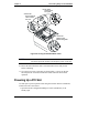
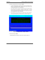
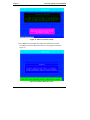
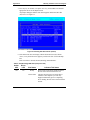
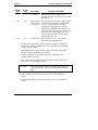
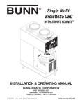
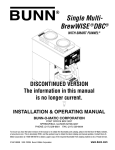
HP NetServer LXr 8500
PCI Hot Plug Utility
User Guide
Printed in August 1999
Notice
The information contained in this document is subject to change without notice.
Hewlett-Packard makes no warranty of any kind with regard to this material, including, but
not limited to, the implied warranties of merchantability and fitness for a particular
purpose. Hewlett-Packard shall not be liable for errors contained herein or for incidental or
consequential damages in connection with the furnishing, performance, or use of this
material. Hewlett-Packard assumes no responsibility for the use or reliability of its software
on equipment that is not furnished by Hewlett-Packard.
This document contains proprietary information that is protected by copyright. All rights
are reserved. No part of this document may be photocopied, reproduced, or translated to
another language without the prior written consent of Hewlett-Packard Company.
The use of trademarks or other designations is for reference purposes only. The following
trademarks are used in this manual:
Intel and Pentium are registered trademarks of Intel Corporation. Microsoft and MS-DOS
are U.S. registered trademarks of Microsoft Corp. Windows and Windows NT are
trademarks of Microsoft Corp. Novell, NetWare, and IntranetWare are registered
trademarks of Novell, Inc.
Hewlett-Packard Company
Network Server Division
Technical Communications / MS 45SLE
10955 Tantau Avenue
Cupertino, CA 95014-0770, USA
© Copyright 1999, Hewlett-Packard Company
ii
Contents
1 PCI Hot Plug Utility for Windows NT ............................................................. 1
Opening the Hot Plug Utility .............................................................................. 1
Opening the PCI Hot Plug Utility ....................................................................... 2
Powering Down a PCI Slot ................................................................................ 5
Removing a Hot Plug Board .............................................................................. 8
Powering Up a PCI Slot ................................................................................... 12
2 PCI Hot Plug Utility for Novell NetWare....................................................... 17
Overview.......................................................................................................... 17
NetWare 5 Requirements............................................................................ 19
Novell Configuration Manager Console ...................................................... 20
Slot Options Menu....................................................................................... 22
Slot Detailed Information Screen................................................................. 24
Opening the User Interface ............................................................................. 25
Powering Down a PCI Slot .............................................................................. 26
Removing a Hot Plug Board ............................................................................ 32
Replacing a Hot Plug Board ............................................................................ 36
Powering Up a PCI Slot ................................................................................... 39
iii
1 PCI Hot Plug Utility for Windows NT
Opening the Hot Plug Utility
Use this topic only for Microsoft's Windows NT 4.0 on the HP NetServer LXr
8500 using the software utility to perform PCI Hot Plug Replacement (or Online
Replacement) operations. This topic and its subsequent topics describe how to
turn power Off and On to the PCI slots (P1-P10) using the PCI Hot Plug Utility.
For Novell's NetWare 5 NOS, go to the topics under Chapter 2 "Hot Plug
Replacement (NetWare)".
CAUTION
To prevent a system crash or hang, never remove a PCI board
from a slot with power on. Always use the Hot Plug Utility to
turn power off to the Hot Plug slot before performing any
replacements.
The PCI board is only Hot Plug-capable if it has a hot plug compliant driver
available and installed on the HP NetServer. If the PCI board is not Hot Plugcapable, remove and replace the board with the HP NetServer's power turned off.
Microsoft’s Windows NT 4.0 does not, by itself, support hot plug replacement,
but HP Configuration Assistant on the HP Navigator CD-ROM, installs the PCI
Hot Plug Utility on the NT server, along with the system software and the drivers
for some of the HP supported PCI Hot Plug boards. Through this Utility,
Windows NT 4.0 does support hot replacement of identical boards. The PCI Hot
Plug Utility is also found in the diskette library on the Navigator CD-ROM. If
using manual installation, follow the installation instructions found in the
readme.txt file to install the Utility on the NT NetServer.
The Hot Plug Utility is used to replace the PCI Hot Plug board in a four-step
process:
1. Turning power off to the PCI slot
2. Removing the PCI board
3. Replacing the PCI board
4. Turning power on to the PCI slot
The Hot Plug Utility is used to turn power off to the PCI slot before removing the
PCI board, and then after replacing the PCI board, it is used to turn power back on
1
Chapter 1
Server Administration Using HP TopTools
to the PCI slot. Refer to the Help File for a description of the PCI Hot Plug
Utility's buttons and functions.
NOTE
The Power Button is the only button required to do basic Hot
Plug Replacement.
Opening the PCI Hot Plug Utility
Use this procedure to open the PCI Hot Plug Utility in Windows NT 4.0.
NOTE
If the left P (Power) LED is lit (green) in the PCI Hot Plug
Utility, the corresponding Power LED on the rear panel will be
green. This is also true for the right A (Attention) LED; that is,
if the right A (Attention) LED is lit (red) in the PCI Hot Plug
Utility, the corresponding Attention LED on the rear panel will
be amber.
1. In Windows NT 4.0, click on the Start button and then select the
Programs menu.
2. From the Programs menu, select PCI Hot Plug and then select the PCI Hot
Plug Utility.
A display similar to the example shown in Figure 1 appears.
This example has 9 slots filled with PCI boards. Slot 1 shows no board
installed and slot 2 has no hot plug compliant driver. Slots 2 to 6 and 9 to
10 all have power applied to the slot, shown by the P (Power) LED turned
on, (left P LEDs are green with Normal in status field) and are operating
normally. Slot 7 has a left P LED on (green), but also has a fault condition
indicated by the right A (Attention) LED (red), with its status field
displaying Link Fault, suggesting a corrective action. Slot 8 has a green P
LED, but has *Mixed – multiple device board (represents a multifunction
adapter) in the status field. See Help file for more information about
functions and buttons.
2
Chapter 1
PCI Hot Plug Utility for Microsoft Windows NT
Figure 1. PCI Hot Plug Utility
3. If no hot plug support appears under Board in the Utility's window
instead of the desired PCI board, one of the following conditions might be
true:
à The PCI Hot Plug board is not supported by a hot plug compliant
software driver.
à The software driver for the PCI Hot Plug board is not properly installed
and loaded.
See Windows NT Help for how to load drivers.
à The PCI board may not use a driver, or the driver is defective.
NOTE
If you have a board without a hot plug compliant driver in one
of the hot plug slots, the board will show up in the Utility as no
hot plug support, and the Utility will not allow you to power
down the slot.
4. Identify the physical location of the desired PCI Hot Plug board, using the
PCI Hot Plug Utility and Figures 2 and 3.
3
Chapter 1
Server Administration Using HP TopTools
Attention
(Amber)
PCI Hot Plug
LED Indicators
P10
P9
P8
P7
P6
P5
Power
P4
P3
P2 P1
Figure 2. PCI Slot Locations (Rear view)
Battery
IDE (CD-ROM)
Configuration
Switch Block
SCSI A
SCSI B
Flexible Disk
Drive
I2C (J1F1)
Remote Control
Board Cable
Auxiliary I2C
PCI LED
Display
Cable
I/O Riser
Slot
10
9
P10-P9
+3.3 VDC
66/33 MHz
Bus 3
8
7
6
P8-P7
+3.3 VDC
66/33 MHz
Bus 2
5
4
P6-P3
+5 VDC
33 MHz
Bus 1
3
2
1
P2-P1
+5 VDC
33 MHz
Bus 0
Remote Control
Board must be
in slot P2.
Figure 3. PCI Slot Locations (I/O Baseboard top view)
4
Chapter 1
PCI Hot Plug Utility for Microsoft Windows NT
Powering Down a PCI Slot
Use this topic to select and power down a PCI slot on the I/O baseboard.
1. Select the desired PCI slot (slot P7) to replace by pointing to it with the
mouse cursor. See Figure 4.
This example has a red A (Attention) LED fault condition associated with
it.
2. Left click on the desired slot (slot P7) with the mouse.
Figure 4. Selecting PCI Slot to Turn Power Off
CAUTION
Opening a PCI hold-down latch with power applied to the slot
may result in a system crash or hang. Always use the Utility to
first power off the slot. Turning off power to any slot will stop
all input (I/O) or services associated with the board while
power is turned off to the slot.
3. Click on the Power button in the upper right of the screen. See Figure 1.
A pop-up prompt appears requesting conformation of this action.
See Figure 5.
5
Chapter 1
Server Administration Using HP TopTools
NOTE
The Power button is the only button required to do basic Hot
Plug Replacement operations.
Figure 5. Pop-up Menu
4. Confirm your selection by clicking on Yes.
As soon as confirmation is complete, the left P (Power) LED in the Utility
window turns off (gray) and the slot status changes from "Link Fault" (or
Normal) to Not Ready. The corresponding Power LED (green) for the PCI
slot on the rear panel will also turn off. This means power to this slot is
turned off. See Figure 6.
6
CAUTION
If the rear panel Power LED for the desired PCI slot does not
turn off, do not attempt to remove the PCI Hot Plug board.
Return to Step 1 in this procedure to ensure you have selected
the correct slot to power down.
NOTE
If you have a PCI board with a non-compliant drive in the
desired PCI slot, the PCI board will show up on the Utility’s
Chapter 1
PCI Hot Plug Utility for Microsoft Windows NT
display with no hot plug support, but the Utility will not allow
you to power down the PCI slot.
Figure 6. PCI Slot is Powered Off
5. If the left P LED in the Hot Plug Utility window stays green, then consider
these steps:
a. Re-install the software driver and then repeat this procedure.
Refer to the Windows NT help file to re-install the driver.
b. Power down the HP NetServer, re-seat the PCI board, power up the
NetServer, and then repeat Steps 2 to 4 in this procedure.
c. Write down the part number and revision level of the PCI board and
then contact the board's manufacturer to determine if a new software
driver is required.
See Help file for further instructions.
d. If your are unable to turn power off to the PCI slot, refer to the
"Installing Accessory Boards" section of your Installation Guide to
power down the HP NetServer, remove the PCI board, and then replace
it with another PCI board.
7
Chapter 1
Server Administration Using HP TopTools
6. If the left P (Power) LED is turned off (gray), go to the next section,
"Removing a Hot Plug Board" to remove the PCI Hot Plug board.
Removing a Hot Plug Board
Use this topic to physically remove a PCI Hot Plug Board from the slot.
1. At the front of the NetServer, remove the front bezel from the HP
NetServer (refer to your Installation Guide).
2. Extend the HP NetServer chassis safely from the rack (refer to your
Installation Guide).
3. Remove the PCI Access Panel (refer to your Installation Guide).
CAUTION
Do not drop screws or other metal objects into the HP
NetServer.
4. Verify power to the desired PCI slot is turned off, by checking the desired
PCI slot's Power LED (right) on the rear panel is off (gray).
The right green Power LED must be OFF. See Figure 7 and Table 1.
5. If not, go back to the section "Powering Down a PCI Slot" and verify you
have turned off power to the correct slot.
6. If you are unable to power down the slot, remove and install the PCI board
in the PCI slot as described in the Installation Guide.
CAUTION
8
To prevent a possible system crash or hang do not continue
with this procedure if you are unable to turn off power to the
PCI slot.
Chapter 1
PCI Hot Plug Utility for Microsoft Windows NT
PCI Hot Plug
LED Indicators
P10
P9
P8
Attention
(Amber)
P7
P6
P5
Power
P4
P3
P2 P1
Figure 7. Hot Plug Slots
The following table decodes the LEDs for each PCI slot:
Table 1. PCI LED Power Code
Amber
LED
Green
LED
Off
On
Power to the slot is on, and the slot is operating
normally. Do not remove the board from the slot.
On
On
Power to the slot is on, but the slot needs attention. See
Help files for choices. Do not remove the board from
the slot.
On
Off
Power to the slot is off, and the slot needs attention.
You can safely remove the board from this slot.
Off
Off
Power to the slot is off. You can remove the board from
this slot.
Indicates This Status
7. If the PCI board has a cable attached to it, label it before continuing.
8. Remove any cables attached to the PCI board.
9
Chapter 1
Server Administration Using HP TopTools
NOTE
Ensure you label any cables attached to the PCI board (disk
controller, NIC, etc.), to identify it later when connecting the
cable to the new or replacement PCI board.
9. Release the PCI hold-down latch to remove the board from the PCI slot.
a. Press the center of the PCI hold-down latch (should hear a click).
See Figure 8.
b. Pull the latch to half open (allows the board to clear the latch).
See Figure 8.
B. Pull latch
to half open from rear.
A. Push here
to release
(should click).
Figure 8. Releasing the PCI Board
NOTE
10
The HP NetServer is shown with its top cover removed for
clarity. Only the PCI Access Panel should be removed for this
procedure. See Step 3.
Chapter 1
PCI Hot Plug Utility for Microsoft Windows NT
10. If necessary, release the PCI card guide latch, allowing the PCI board to
clear the card guide. See Figure 9.
The PCI hold-down latch and PCI card guide latch are used to keep the
PCI boards in place, since a screw is no longer used.
PCI Board
Guide Latch
Open Latch
Figure 9. Opening the PCI Card Guide Latch
CAUTION
When handling electronic components, wear a wrist strap and
use a static-dissipating work surface connected to the chassis
when handling components. Ensure the metal of the wrist
strap contacts your skin.
11
Chapter 1
Server Administration Using HP TopTools
11. Grasp the edge of the PCI board firmly and pull upward. See Figure 10.
Try to pull the board straight up without wiggling it side to side along the
length of the board.
Remove board
Ensure
PCI hold-down
latch is at least half open
before removing board.
Figure 10. Removing PCI Boards
12. Place the board on an anti-static surface.
13. Go to the section "Replacing a Hot Plug Board" in your Installation Guide
to install a new or replacement, but identical PCI Hot Plug board in the
PCI slot.
Powering Up a PCI Slot
Use this procedure to apply power to a PCI slot (after replacing an existing PCI
Hot Plug board with an identical PCI Hot Plug board).
1. If not already open, select the PCI Hot Plug Utility from Programs menu.
2. Left click on the desired PCI slot (Slot 7) with the Not Ready status.
12
Chapter 1
PCI Hot Plug Utility for Microsoft Windows NT
Figure 11. Selecting the PCI Slot to Turn Power On
NOTE
If the A (Attention) LED was lit (red) when you powered down
the slot, it will remain lit (red) until power to the slot is turned
on.
13
Chapter 1
Server Administration Using HP TopTools
3. Click on the Power button in the upper right of the menu. See Figure 11.
A pop-up prompt appears asking you to confirm your choice. See Figure
12.
Figure 12. Pop-up Menu
4. Confirm your selection by clicking on Yes.
The pop-up prompt should disappear and the left P LED for the slot (slot 7)
should turn green and after a few seconds the status should change from
"Not Ready" to Normal. See Figure 13.
14
Chapter 1
PCI Hot Plug Utility for Microsoft Windows NT
5. As the left P LED turns green, observe the right A LED and the board
status while you wait a few seconds for the software driver to initialize the
PCI board. See Figure 13.
The left P (Power) LED should be green at this point.
Figure 13. PCI Hot Plug Utility –Power Turned On
6. If the right A (Attention) LED stays red in the Hot Plug Utility window
and the rear panel Attention LED stays Amber, then consider these steps:
a. Ensure all the required cables are attached to the adapter.
b. Power down the slot as described in Steps 2 to 5 of the section
"Powering Down the PCI Slot" and then re-seat the PCI board.
c. Ensure an identical PCI board was used as a replacement.
d. Write down the part number and revision level of the PCI board and
then contact the manufacturer to determine if a new software driver is
required.
If necessary, install a new driver and repeat this procedure. See the
Help file for more information.
7. Observe the two LEDs for this slot on the rear panel.
15
Chapter 1
Server Administration Using HP TopTools
The right Power LED on the rear panel LED display should be green and
the left Attention LED should be off (gray) at this point.
8. If possible, verify the PCI board's operation, before continuing.
9. If you are assured of the PCI board's operation, including its driver,
continue with the next step.
10. If all desired PCI Hot Plug boards have been installed, replace the PCI
access panel.
Refer to the section "Removing the PCI Access Panel" in your Installation
Guide.
NOTE
The PCI access panel uses the only short T-15 Torx® screws on
the HP NetServer, to prevent the top cover from catching on
the center support, when it is removed with the PCI access
panel in place.
CAUTION
To prevent damage to cables, or a disruption in service due to
a disconnection of cables, use caution when sliding the chassis
into the rack, if not using the Cable Management Arm.
11. If chassis work is complete, slide the HP NetServer chassis back into the
rack (refer to your Installation Guide).
12. Return the HP NetServer to normal operation (refer to your Installation
Guide).
16
2 PCI Hot Plug Utility for Novell
NetWare
Overview
Use this topic only for Novell's NetWare 5's software interface to perform PCI
Hot Plug Replacement (or Online Replacement) operations. This topic and its
subsequent topics describe how to turn power Off and On to the PCI slots (P1P10) using the software interface.
For Microsoft's Windows NT 4.0 NOS, go to the topics in Chapter 1.
CAUTION
To prevent a system crash or hang never remove a PCI board
from a slot with power on. Always use the software interface
NCMCON (Novell Configuration Manager Console) to turn
off power to the slot before performing any Hot Plug
operations.
The PCI board is only Hot Plug-capable if it has a hot plug compliant driver
available and installed on the HP NetServer. If the PCI board is not Hot Plugcapable, remove and replace the board with the HP NetServer's power turned off.
NetWare 5 implements hot plug replacement of a PCI board in all ten slots, P1
through P10, through a four-step process:
1. Powering down the PCI slot
2. Removing the PCI board
3. Replacing the PCI board
4. Powering up the PCI slot
Turning power off and on to the PCI slots is performed through Novell's user
interface, Novell Configuration Manager Console (NCMCON). The poweringdown step includes unloading the driver associated with the selected board and
then turning off power to the slot. Once power has been turned off it is possible to
safely remove the PCI board and then replace it with an identical PCI board.
The powering-up step can only be performed after the new board has been
installed in the slot. The powering-up step includes loading the driver to the PCI
board and then safely turning on power to the slot.
17
Appendix B
Warranty, Software License and Support
The rear of the chassis provides two LEDs for each PCI Hot Plug slot to indicate
its status. The LED indicators are related to the status shown in the user interfaces'
main menu. The following table decodes the LEDs for each PCI slot. See Table 2
and Figure 14.
NOTE
If the user interface, Novell Configuration Manager Console
(NCMCON), displays a No in the “Hot Plug” column for each
PCI (P1-P10) slot, then the correct hot plug controller driver
(phpsbd.nlm) is not loaded. See Figure 14 and the Help files.
Table 2. PCI (Hot Plug) LED Indicators (rear view)
Amber
LED
Off
Green
LED
On
Slot
Status
Ready
Indicates This Status
Powered on, but no driver loaded for board. Do not
remove the board from the slot.
Powered On The PCI slot just power on, but the driver initiation is
not complete yet. This only happens momentarily prior
to completing driver loading. Do not remove the board
from the slot.
Active
Power to the slot is on, and the slot is operating
normally. Do not remove the board from the slot.
On
Off
Powered
Off (wrong
board or no
board)
Power to the slot is off, but the Amber LED is on, due
to a failure in the Hot Replacement process. Typically
this is the result of installing the wrong board, because
the replacement board must be the same type as the
original PCI board. This also occurs if the board is
removed, emptying the slot, and power is turned on.
You can safely remove the board from this slot.
Off
Off
Powered
Off
Power to the slot is off. You can remove the board from
this slot.
18
Chapter 2
PCI Hot Plug Utility for Novell NetWare
Figure 14. Main User Interface Screen
NetWare 5 Requirements
The PCI Hot Plug feature is operational in all ten slots, if:
• The NetWare's Hot Plug Controller driver (phpsbd.nlm) is loaded.
• The PCI Hot Plug board has a driver loaded or a drive for loading.
The Hot Plug feature must be loaded before the Hot Plug feature can be
enabled. If you selected Express or Guided Setup, all the NetWare
Loadable Modules (NLMs) were installed onto the system, along with the
correct drivers.
The proper PCI Hot Plug Controller Driver is phpsbd.nlm, version 1.10 (or
greater). During Express installation, the controller driver, phpsbd.nlm, is
automatically installed on the HP NetServer from the HP Navigator CD.
If you choose Custom, you may not have loaded the correct drivers
(NLMs). When performing a manual install, it is necessary to obtain the
phpsbd.nlm driver from the Navigator CD and copy it into the system
directory. This file can be obtained from the Navigator diskette library
"PCI Hot Plug for NetWare 5". In either case, ensure you load it prior to
running the NetWare 5.0 Hot Plug user interface (ncmcon.nlm) or
performing any Hot Plug operations.
19
Appendix B
Warranty, Software License and Support
• Refer to the Help files and readme.txt file on the PCI Hot Plug - NetWare 5
diskette created from the HP NetServer Navigator CD-ROM or the
NetWare documentation concerning the Hot Plug option for more
information.
• Refer also to HP's Help files and readme.txt file and the NetWare
documentation for loading the Hot Plug drivers onto the HP NetServer.
NOTE
The order of loading the adapter board drivers and the other
NetWare loadable modules (NLMs) is important. Please refer
to the readme.txt file on the PCI Hot Plug - NetWare 5 diskette
for details.
Novell Configuration Manager Console
The Novell Configuration Manager Console (NCMCON) is the Hot Plug user
interface and provides status information, including error status, on each PCI slot
on the I/O baseboard (P1-P10). The NCMCON user interface provides three
menus to display the PCI Hot Plug status and actions. See Figures 15 through 17.
• Main Menu – This menu displays each PCI slot, PCI board, and its status.
See Figure 15 and Table 3.
• Slot Options – This menu is used to change the operational status of the
PCI slot. See Figure 16 and Table 4.
• Slot Detailed Information – This screen provides detailed information
about the PCI slot and the PCI board installed in the slot. See Figure 17
and Table 5.
The Slot Options screen or the Slot Detailed Information screen displays
on top of the Main Menu screen, when the Enter key is used to highlight a
PCI slot in the Main Menu screen.
20
Chapter 2
PCI Hot Plug Utility for Novell NetWare
Figure 15. Main Menu Display
Table 3. Main Menu Fields and Descriptions
Field
Description
Slot Number
This field provides the PCI slot number for each PCI slot on
the system board numbered from 1 to 10.
Hot Plug
This field indicates with a Yes or No if the PCI slot supports
the Hot Plug feature. If slots P1 through P10 display No,
then the controller driver phpsbd.nlm is not loaded. See
Figure 15.
Adapter Name
This field indicates if a board is not present (No adapter
present) or provides the name and model of the adapter in
the PCI slot. If the adapter board can not be identified,
Unclassified PCI Device is listed.
21
Appendix B
Warranty, Software License and Support
Field
Slot Status
Description
This field provides the operational status of each PCI slot.
The seven possible indications in this field, with descriptions
of each, are:
Powered Off – Power to the slot is turned off and an adapter
may or may not be present.
Powered On – Power to the slot is turned On, but there is no
adapter in the PCI slot. This may also appear, momentarily,
prior to completing driver loading after a board replacement.
Ready – Power to the slot is turned On, an adapter is in the
slot, but there is no driver loaded for the adapter. Some
boards do not require a driver to operate; for example, the
HP TopTools Remote Control card in PCI slot 2.
Active – Power to the slot is turned on, an adapter is in the
slot, the adapter is using the loaded driver, and the adapter is
operating correctly.
Failed – The driver for this adapter (Hot Plug or non-Hot
Plug) indicates a device failure. Only Hot Plug adapters can
be removed and replaced without shutting down the system
to replace with a good adapter of the same type.
Degraded – A function on the multi-device adapter has
failed, but other functions on the adapter continue to operate
normally.
Processing – This indicates an action of some kind is being
performed on the slot or adapter, that is, the interface utility
may be searching for the drive to load, or it may be
unloading the driver before turning power off, etc.
Slot Options Menu
This menu appears on top of the Main Menu and lists the available options for
changing or displaying the operational status of the PCI Hot Plug slot. See Figure
16 and Table 4.
The options displayed in the Slot Options menu, just above the Slot Detailed
Information topic, depend on three items:
• The status of the PCI slot or PCI adapter board
• The System Capabilities
22
Chapter 2
PCI Hot Plug Utility for Novell NetWare
NOTE
If a board slot is selected without the phpsbd.nlm loaded, the
Slot Detailed Information screen will display automatically.
Figure 16. Slot Options Menu
Table 4. Slot Options Menu Selections
Slot Menu Item
Description
Remove Adapter
This indicates an adapter is in the slot and the slot is presently powered
on.
Replace Adapter
This indicates the power to the slot is turned Off and the system only
supports Hot Replacement.
Hot Replacement means the existing adapter can be removed and must
be replaced with an identical adapter.
Slot Detailed
Information
This option is always present in the Slot Options menu. Selecting this
option displays all pertinent information about the selected PCI slot
and the adapter board in the PCI slot. See the topic Slot Detailed
Information for more information.
23
Appendix B
Warranty, Software License and Support
Slot Menu Item
Add Adapter
Description
These Slot Options are not supported by the HP NetServer LXr 8500.
Power Off Slot
Power On Slot
Slot Detailed Information Screen
The Slot Detailed Information screen displays all the pertinent information about
the selected PCI slot and the adapter board in the PCI slot. See Figure 17 and
Table 5.
NOTE
If a board slot is selected when the phpsbd.nlm is not loaded,
the Slot Detailed Information screen displays automatically.
Figure 17. Slot Detailed Information Screen
24
Chapter 2
PCI Hot Plug Utility for Novell NetWare
Table 5. Slot Detailed Information Screen Fields
Field or Item
Description
Screen Title:
The screen title indicates the PCI slot number, and if a board is
installed, the name and model of the adapter board.
Slot Information:
This field provides the bus type (PCI) and number, the speed
capability (33 or 66 MHz) and actual speed of the bus, and the bit
number (32 or 64-bit).
Hot Plug:
This field indicates the slot is Hot Plug-capable; Yes or No. All
slots should have Yes listed.
Slot Status:
This indicates the present status of the PCI slot or the adapter.
Device and Driver Information:
HIN:
This indicates the NetWare Hardware Instance Number (HIN) of
each device.
Registered Driver:
This indicates the driver name loaded for this adapter board.
Driver Status:
This indicates the driver status:
Active – The driver is loaded for the device.
Inactive – There is no driver loaded for the device.
Failed – The adapter device has failed.
Suspended – The driver is loaded, but activity is suspended
while the adapter is being added.
Opening the User Interface
Use this topic to open and use NetWare 5's software user interface. The Novell
Configuration Manager Console (NCMCON) is used as the user interface to
control the Hot Plug slots. It is used to remove or apply power to PCI slots and
remove or load the driver to the slot. The Hot Plug slots must be powered off
before removing PCI boards from the slots. The HP NetServer LXr 8500 supports
Hot Plug operations for all ten PCI slots (P1 through P10).
CAUTION
To prevent a system crash or hang, do not open the PCI slot's
PCI hold-down latch with power applied to the slot.
1. To start the Novell Configuration Manager Console (NCMCON), type the
following line at the NetWare console prompt.
25
Appendix B
Warranty, Software License and Support
ncmcon.nlm
2. Press the Enter (or Return) key.
The console (NCMCON) should load and the user interface’s main menu
will display on the monitor. All 10 PCI slots are shown in the display and
all slots (P1 through P10) are used for hot plug operations and controlled
by NCMCON. See Figure 18.
NOTE
A Yes should be displayed in the "Hot Plug" column for each
PCI Hot Plug (P1-P10) slot. If No is displayed instead, then the
correct hot plug controller driver (phpsbd.nlm) is not loaded.
See the HP Help File for more information.
Figure 18. Main Menu Display
3. To turn power off to a PCI slot go to the next section, "Powering Down a
PCI Slot".
Powering Down a PCI Slot
Use this topic to turn power off to the PCI slot before removing the adapter board
from the PCI slot.
26
Chapter 2
PCI Hot Plug Utility for Novell NetWare
1. Open the Novell Configuration Manager Console (NCMCON), if it is not
already open.
CAUTION
To prevent a system crash or hang never open the PCI holddown latch with power on to the desired slot. Always use the
software interface to turn off power to the slot before physical
removing the PCI board.
2. Select a PCI slot (P1-P10) to remove the PCI Hot Plug board (P5).
Use the Up and Down Arrow keys to select or highlight a desired PCI slot.
3. Press the Enter key when you have selected the desired slot (P5).
à If the phpsbd.nlm is loaded, the Slot Options popup menu displays;
continue with Step 4. See Figure 19.
à If the phpsbd.nlm is not loaded, the Slot Detailed Information screen
displays. See the Help file for more information.
Figure 19. Slot Options Menu – Remove Adapter
4. Select Remove Adapter in the Slot Options popup menu. See Figure 19.
Use the Up and Down Arrow keys to select or highlight the option.
27
Appendix B
Warranty, Software License and Support
5. Press the Enter key when you have selected the desired option.
The Slot Options popup menu disappears and displays the popup menus in
Figure 20, titled:
Driver Is Loaded – Next Step
NOTE
The driver is removed from control of the PCI slot, but not
from the list of drivers held in the HP NetServer under
NetWare 5.
Figure 20. Driver Is Loaded Screen
6. Select Yes in the pop-up menu. See Figure 20.
à If the PCI board is a Disk Drive Controller, with various drives
connected to it and operating, a screen appears concerning dismounting
the disk drives. See Figure 21.
à If the PCI board type is not a Disk Drive Controller, the pop-up menu
disappears and the main menu remains, but the slot’s status (slot P5)
changes from "Ready" to Powered Off. See Figure 22 and skip to Step
8.
28
Chapter 2
PCI Hot Plug Utility for Novell NetWare
Figure 21. Disk Controller Dismount Screen
CAUTION
Selecting Yes to the "Forcing A Remove" screen will
dismount any disk drives connected to a Disk Drive
Controller, which prevents access to the disk drives by any
applications or users through the HP NetServer.
7. If you are sure it is safe to dismount the drives from the Disk Drive
Controller, select Yes to continue.
The "Force A Remove" screen disappears and the main menu remains, but
the slot’s status (slot P5) changes from "Ready" to Powered Off. See
Figure 22.
29
Appendix B
Warranty, Software License and Support
Figure 22. PCI Slot Changes to Powered Off
8. Verify the corresponding green Power LED on the rear of the HP
NetServer is turned off, which verifies the correct PCI slot has been
powered down.
Refer to Figure 23 and Table 6 before continuing with the procedure.
CAUTION
30
If the LEDs on the rear of the chassis indicate power is still
applied to the slot, return to Step 2 in this procedure to ensure
you have selected the correct slot to power down. See Figure
23 and Table 6.
Chapter 2
PCI Hot Plug Utility for Novell NetWare
PCI Hot Plug
LED Indicators
P10
P9
P8
Attention
(Amber)
P7
P6
P5
Power
P4
P3
P2 P1
Figure 23. PCI Slots and LED Indicators
Table 6. PCI (Hot Plug) LED Code (Rear of Chassis)
Amber
LED
Green
LED
Slot
Status
Off
On
Ready
Indicates This Status
Powered on, but no driver loaded for board. Do not
remove the board from the slot.
Powered On The PCI slot just power on, but the driver initiation is
not complete yet. This only happens momentarily prior
to completing driver loading. Do not remove the board
from the slot.
Active
On
Off
Powered
Off (wrong
board or no
board)
Off
Off
Powered
Power to the slot is on, and the slot is operating
normally. Do not remove the board from the slot.
Power to the slot is off, but the Amber LED is on, due
to a failure in the Hot Replacement process. Typically
this is the result of installing the wrong board, because
the replacement board must be the same type as the
original PCI board. This also occurs if the board is
removed, emptying the slot, and power is turned on.
You can safely remove the board from this slot.
Power to the slot is off. You can safely remove the
31
Appendix B
Warranty, Software License and Support
Off
board from this slot.
9. If the Slot Status for the desired PCI slot changes to Powered Off, go to
next section, "Removing a Hot Plug Board", to physically remove the PCI
board from the PCI slot (slot P5).
Removing a Hot Plug Board
Use this topic to physically remove a PCI Hot Plug Board from its PCI slot.
1. At the front of the HP NetServer, remove the front bezel from the
NetServer (refer to your Installation Guide).
2. Extend the HP NetServer chassis safely from the rack (refer to your
Installation Guide).
3. Remove the PCI Access Panel (refer to your Installation Guide).
CAUTION
Do Not Drop Screws or Other Metal Objects into the HP
NetServer.
4. Verify power to the desired PCI slot is turned off, by checking the power
LED associated with the desired PCI slot. See Figure 24 and Table 7.
The green Power LED must be OFF, before attempting to open the PCI
hold-down latch.
32
Chapter 2
PCI Hot Plug Utility for Novell NetWare
PCI Hot Plug
LED Indicators
P10
P9
P8
Attention
(Amber)
P7
P6
P5
Power
P4
P3
P2 P1
Figure 24. Hot Plug Slots and LEDs
Table 7 decodes the LEDs for each PCI slot:
Table 7. PCI (Hot Plug) LED Codes (rear panel view)
Amber
LED
Off
Green
LED
Slot
Status
On
Ready
Indicates This Status
Powered on, but no driver loaded for board. Do not
remove the board from the slot.
Powered On The PCI slot just power on, but the driver initiation is
not complete yet. This only happens momentarily prior
to completing driver loading. Do not remove the board
from the slot.
Active
On
Off
Powered
Off (wrong
board or no
board)
Power to the slot is on, and the slot is operating
normally. Do not remove the board from the slot.
Power to the slot is off, but the Amber LED is on, due
to a failure in the Hot Replacement process. Typically
this is the result of installing the wrong board, because
the replacement board must be the same type as the
original PCI board. This also occurs if the board is
removed, emptying the slot, and power is turned on.
You can safely remove the board from this slot.
33
Appendix B
Amber
LED
Off
Warranty, Software License and Support
Green
LED
Slot
Status
Off
Powered
Off
Indicates This Status
Power to the slot is off. You can safely remove the
board from this slot.
5. If not, go back to the software interface NCMCON and verify you have
turned off power to the correct slot.
6. If you are unable to power down the slot, remove and install a PCI board in
the Hot Plug slot as described in your Installation Guide.
7. Do not continue with this procedure, if you are unable to power down the
desired PCI slot.
CAUTION
To prevent a system crash or hang do not open the PCI holddown latch, if you are unable to turn off power to the PCI slot,
using the software interface (NCMCON).
8. Press the PCI hold-down latch to release the PCI board in the slot. See
Figure 25.
B. Pull latch
to half open from rear.
A. Push here
to release
(should click).
Figure 25. Opening the PCI Hold-Down Latch
34
Chapter 2
PCI Hot Plug Utility for Novell NetWare
The PCI hold-down latch is used to keep the PCI boards in place and to
activate the PCI slot power switch and PCI LED board.
NOTE
The HP NetServer is shown with its top cover removed for
clarity. Only the PCI Access Panel should be removed for this
procedure.
9. Open the PCI board-guide latch before removing the PCI board. See Figure
26.
CAUTION
Do not bend the PCI board to remove it from the slot.
If the PCI board is full-length, the PCI board guide latch at the
rear of the PCI slot is used to hold the board in place. The
latch at the top of PCI board guide prevents the board from
moving during HP NetServer transportation and handling
when performing PCI Hot Plug operations.
PCI Board
Guide Latch
Open Latch
Figure 26. PCI Board Guide Latch
35
Appendix B
CAUTION
Warranty, Software License and Support
When handling electronic components, wear a wrist strap and
use a static-dissipating work surface connected to the chassis
when handling components. Ensure the metal of the wrist
strap contacts your skin.
10. Grasp the edge of the PCI board firmly and pull upward. See Figure 27.
Try to pull the board straight up without wiggling it side to side along the
length of the board.
Remove board
Ensure
PCI hold-down
latch is at least half open
before removing board.
Figure 27. Removing PCI Boards
11. Place the PCI board on a static free surface.
12. Go to the next section "Replacing a PCI Hot Plug Board" to install a new,
but identical PCI Hot Plug board in the PCI slot.
Replacing a Hot Plug Board
Use this topic to replace a PCI Hot Plug Board. The following conditions must be
met before replacing a PCI Hot Plug Board:
36
Chapter 2
PCI Hot Plug Utility for Novell NetWare
• The desired PCI slot must be powered off.
• The replacement PCI Hot Plug board must be identical to the board it
replaces, or use the same software driver.
NOTE
Some full-length PCI boards have a plastic "handle" (board
extender) on one end. If the handle interferes with the board's
installation, remove the handle from the board. Do not bend
the board to make it fit.
1. Read the documentation included with the adapter board and follow any
special instructions provided.
CAUTION
To prevent a system crash or hang do not attempt this
procedure if you are unable to turn off power to the PCI Hot
Plug slot.
2. Verify the Power LED above the desired PCI slot on the rear panel is off.
CAUTION
When handling electronic components, wear a wrist strap and
use a static-dissipating work surface connected to the chassis
when handling components. Ensure the metal of the wrist
strap contacts your skin.
3. Remove the PCI board from its protective packaging.
CAUTION
Do not bend the PCI board to install it into the slot.
If the full-length PCI board has a handle on the end of the
board that prevents its installation, remove the handle before
installing the board.
4. If the PCI board is a full-length board, with a handle attached to its end,
remove the handle before installing the board into the slot.
5. Align the board with its slot, along its full length, and position it into the
slot. See Figure 28.
6. Push the PCI board down into its PCI connector in the I/O baseboard.
37
Appendix B
Warranty, Software License and Support
Insert board
Ensure
PCI hold-down
latch is at least half open
before inserting board.
Figure 28. Installing the Accessory Board
7. Close the PCI hold-down latch, by pushing it in from the rear of the
NetServer, until it clicks. See Figure 29.
The PCI hold-down latch should click when you push it into place.
8. Close the latch on the PCI board guide. See Figure 29.
9. If the installed accessory board requires an external connection, or a
connection to the I/O baseboard, ensure the cable is properly attached.
Refer to the accessory board documentation for connection requirements.
38
Chapter 2
PCI Hot Plug Utility for Novell NetWare
B. The latch
should click
into place.
A. Push the
PCI hold-down
latch in from
the rear.
C. Close the
latch on the
PCI board guide.
Figure 29. Closing the PCI Hold-Down Latch
NOTE
If the PCI hold-down latch does not fully close (click), the slot
will not be powered on when you attempt to power on the slot.
10. Ensure the PCI hold-down latch is closed and the board is fully seated,
before continuing.
11. Go to the next section, "Powering UP the PCI Slot", to power up the slot
and complete the verification of the PCI board's software driver and its
operation.
Powering Up a PCI Slot
Use this topic to power up the PCI slot using the software interface NCMCON,
which selects the correct driver.
1. Open the Novell Configuration Manager Console (NCMCON), if not
already open.
39
Appendix B
Warranty, Software License and Support
2. Select the desired PCI slot (P5) and press Enter.
à If a PCI board does not occupy the board slot, an error message screen
displays, "No Adapter Detected", and the Amber LED for the slot turns
on. See HP Help File for more information.
à If the replacement PCI board is not identical to the previous PCI board,
an error message screen displays, "Adapter Is Not the Same". You must
replace with an identical PCI board. Replace the board and repeat Step
2. See HP Help File for more information.
à If the identical PCI board occupies the board slot, the "Power On Slot"
screen opens and provides you with a choice as shown in Figure 30.
Figure 30. Sot Options Menu – Replace Adapter
3. Select Yes and press Enter.
A prompt appears at the bottom of the screen as shown in Figure 31.
40
Chapter 2
PCI Hot Plug Utility for Novell NetWare
Figure 31. Cable Connection Prompt
4. Press Enter to acknowledge the prompt and continue the procedure.
The Hardware Insertion/Removal Detection screen appears as shown in
Figure 32.
Figure 32. Hardware Detection screen
41
Appendix B
Warranty, Software License and Support
5. Press any key to continue, except the "Esc" key, and NetWare will load the
appropriate driver for the adapter board.
All prompts disappear and the main menu appears with desired PCI Slot
(P5) active. See Figure 33.
Figure 33. Hot Plug Slot Powered On (Active)
6. If the main menu does not display with the desired PCI slot (P5) shown
Active, verify the PCI board is properly seated in the slot. See the HP Help
File.
Refer to Table 8 to decode the PCI (Hot Plug) LED indicators.
Table 8. PCI (Hot Plug) LED Code (rear panel view)
Amber
LED
Green
LED
Slot Status
Off
On
Ready
Powered On
42
Indicates This Status
Powered on, but no driver loaded for board.
Do not remove the board from the slot.
The PCI slot just power on, but the driver
initiation is not complete yet. This only
happens momentarily prior to completing
driver loading. Do not remove the board from
the slot.
Chapter 2
Amber
LED
PCI Hot Plug Utility for Novell NetWare
Green
LED
Slot Status
Indicates This Status
Active
Power to the slot is on, and the slot is
operating normally. Do not remove the board
from the slot.
On
Off
Powered Off
(wrong board
or no board)
Power to the slot is off, but the Amber LED is
on, due to a failure in the Hot Replacement
process. Typically this is the result of
installing the wrong board, because the
replacement board must be the same type as
the original PCI board. This also occurs if the
board is removed, emptying the slot, and
power is turned on. You can safely remove
the board from this slot.
Off
Off
Powered Off
Power to the slot is off. You can safely
remove the board from this slot.
7. If you replaced a Disk Drive Controller board, causing it to dismount its
disk drives, re-mount the disk drives to ensure the Disk Drive Controller
board is working correctly.
Remounting the drives must be done outside the Novell Configuration
Manager Console (NCMCON) user interface.
8. If you are assured of the PCI board's operation, including its driver,
continue with the next step.
9. If all desired Hot Plug boards have been replaced, replace the PCI access
panel (refer to your Installation Guide).
CAUTION
To prevent damage to cables, use caution when sliding the
chassis into the rack, if the Cable Management Arm is not
used.
10. Slide the chassis slowly back into the rack (refer to your Installation
Guide).
11. Return the HP NetServer to normal operation (refer to your Installation
Guide).
43