1
VOLVO C70
Owners Manual
Web Edition
DEAR VOLVO OWNER
THANK YOU FOR CHOOSING VOLVO
We hope you will enjoy many years of driving pleasure in your Volvo.
The car has been designed for the safety and comfort of you and your
passengers. Volvo is one of the safest cars in the world. Your Volvo
has also been designed to satisfy all current safety and environmental
requirements.
In order to increase your enjoyment of the car, we recommend that
you familiarise yourself with the equipment, instructions and maintenance information contained in this owner's manual.
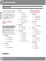
Table of contents
00 01 02
00 Introduction
01 Safety
Important information............................... 10
Volvo and the environment....................... 14
Seatbelts...................................................
Airbag system...........................................
Airbags......................................................
Activating/deactivating the airbag*...........
Side airbags (SIPS bags)..........................
Inflatable Curtain (DMIC)...........................
WHIPS.......................................................
Roll-Over Protection System (ROPS)........
When the systems deploy.........................
Crash mode..............................................
Child safety...............................................
02 Instruments and controls
18
21
22
24
26
28
29
31
32
34
35
Overview, left-hand drive cars..................
Overview, right-hand drive cars................
Driver's door control panel.......................
Combined instrument panel......................
Indicator and warning symbols.................
Information display...................................
Electrical socket........................................
Lighting panel...........................................
Left-hand stalk switch...............................
Right-hand stalk switch............................
Cruise control*..........................................
Keypad in the steering wheel*..................
Steering wheel adjustment, hazard warning flashers................................................
Parking brake............................................
Power windows.........................................
Windows, rearview and door mirrors........
Personal preferences................................
46
48
50
51
52
56
58
59
62
65
67
69
70
71
72
74
78
HomeLink *.............................................. 81
4
* Option/accessory, for more information, see Introduction.
Table of contents
03 04 05
03 Climate control
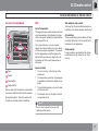
General information on climate control.....
Electronic climate control, ECC*...............
Air distribution...........................................
Fuel-driven engine block heater and passenger compartment heater*....................
Fuel-driven auxiliary heater* (diesel).........
86
88
91
92
95
04 Interior
05 Locks and alarm
Front seats................................................ 98
Electrically operated roof ....................... 103
Wind deflector*....................................... 106
Interior lighting........................................ 107
Storage spaces in the passenger compartment ................................................. 110
Cargo area.............................................. 114
Remote control key with key blade.........
Active locks.............................................
Privacy locking*.......................................
Keyless drive*..........................................
Battery in remote control key..................
Locking and unlocking............................
Alarm*.....................................................
120
123
124
126
129
130
134
* Option/accessory, for more information, see Introduction.
5
Table of contents
06 07 08
6
06 Starting and driving
07 Wheels and tyres
General.................................................... 140
Refuelling................................................ 142
Alcoguard*.............................................. 146
Starting the engine.................................. 150
Keyless drive*.......................................... 152
Manual gearbox...................................... 153
Automatic gearbox.................................. 154
Brake system.......................................... 159
DSTC – Stability and traction control system*......................................................... 161
Park Assist*............................................. 163
BLIS* – Blind Spot Information System. . 165
Towing and recovery.............................. 168
Start assistance...................................... 172
Driving with a trailer................................ 173
Towing equipment*................................. 175
Detachable towbar* ............................... 177
Loading................................................... 181
Adjusting headlamp pattern.................... 182
General....................................................
Tyre pressure..........................................
Warning triangle* and spare wheel * ......
Changing wheels....................................
Emergency puncture repair* ..................
* Option/accessory, for more information, see Introduction.
08 Car care
186
190
191
194
196
Cleaning.................................................. 202
Touching up paintwork........................... 206
Rustproofing........................................... 207
Table of contents
09 10 11
09 Maintenance and service
Volvo service...........................................
Self-maintenance....................................
Bonnet and engine compartment...........
Oils and fluids.........................................
Wiper blades...........................................
Battery.....................................................
Replacing bulbs......................................
Fuses......................................................
10 Infotainment system
210
211
212
214
220
221
223
229
General....................................................
Audio functions.......................................
Radio functions.......................................
CD functions...........................................
Menu structure – audio system..............
Phone functions*.....................................
Menu structure – phone*.........................
Bluetooth handsfree*..............................
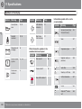
11 Specifications
238
240
245
250
253
254
261
264
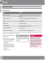
Type designation.....................................
Dimensions and weights.........................
Engine specifications..............................
Engine oil................................................
Fluids and lubricants...............................
Fuel.........................................................
Wheel and tyres, dimensions and pressure ........................................................
Electrical system.....................................
Type approval.........................................
Symbols in the display............................
272
274
277
278
280
282
284
286
288
289
* Option/accessory, for more information, see Introduction.
7
Table of contents
12
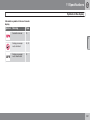
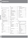
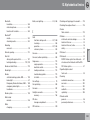
12 Alphabetical Index
Alphabetical Index.................................. 292
8
Table of contents
9
Introduction
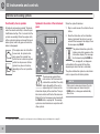
Important information
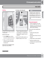
Reading the Owner's Manual
Introduction
A good way of getting to know your new car is
to read the owner's manual, ideally before your
first journey. This will give you the opportunity
to familiarise yourself with new functions, to
see how best to handle the car in different situations, and to make the best use of all the
car's features. Please pay attention to the
safety instructions contained in the manual.
The specifications, design features and illustrations in this owner's manual are not binding.
We reserve the right to make modifications
without prior notice.
©
In the event of uncertainty over what is standard or an option/accessory, contact a Volvo
dealer.
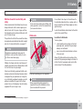
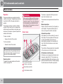
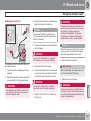
Special texts
WARNING
Warning texts advise of a risk of personal
injury.
IMPORTANT
Important texts advise of a risk of material
damage.
All types of option/accessory are marked with
an asterisk*.
In addition to standard equipment, this manual
also describes options (factory fitted equipment) and certain accessories (retrofitted extra
equipment).
The equipment described in the owner's manual is not available in all cars - they have different equipment depending on adaptations
for the needs of different markets and national
or local laws and regulations.
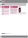
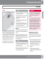
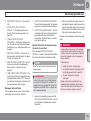
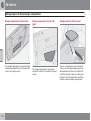
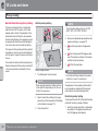
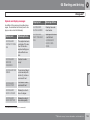
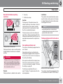
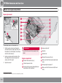
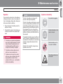
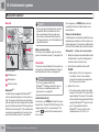
The car contains different types of decal which
are designed to convey important information
in a simple and clear manner. The decals in the
car have the following descending degree of
importance for the warning/information.
Warning for personal injury
NOTE texts give advice or tips that facilitate
the use of features and functions for example.
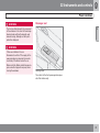
Footnote
There is footnote information in the owner's
manual that is located at the bottom of the
page. This information is an addition to the text
that it refers to via a number. If the footnote
refers to text in a table then letters are used
instead of numbers for referral.
Message texts
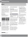
There are displays in the car that show text
messages. These text messages are high-
10
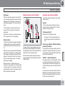
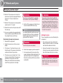
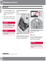
Decals
NOTE
Volvo Car Corporation
Option
lighted in the owner's manual by means of the
text being slightly larger and printed in grey.
Examples of this are in menu texts and message texts on the information display (e.g.
AUDIO SETTINGS).
* Option/accessory, for more information, see Introduction.
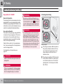
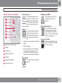
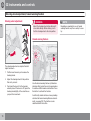
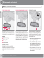
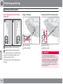
G031590
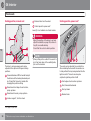
Black ISO symbols on yellow warning field,
white text/image on black message field. Used
to indicate the presence of danger which, if the
Introduction
Important information
warning is ignored, may result in serious personal injury or fatality.
Information
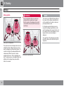
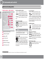
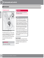
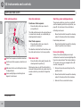
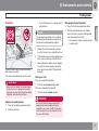
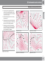
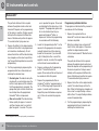
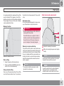
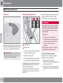
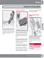
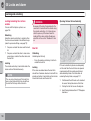
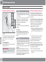
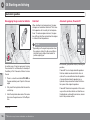
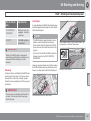
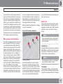
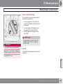
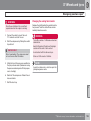
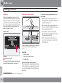
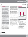
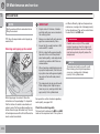
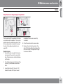
Procedure lists
Procedures where action must be taken in a
certain sequence are numbered in the owner's
manual.
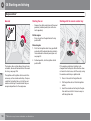
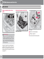
Risk of property damage
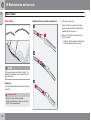
When there is a series of illustrations for
step-by-step instructions each step is
numbered in the same way as the corresponding illustration.
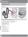
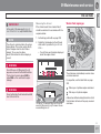
G031592
G031593
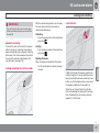
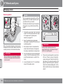
There are numbered lists with letters adjacent to the series of illustrations where the
order of the instructions is not significant.
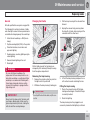
White ISO symbols and white text/image on
black or blue warning field and message field.
Used to indicate the presence of danger which,
if the warning is ignored, may result in damage
to property.
White ISO symbols and white text/image on
black message field.
NOTE
The labels shown in the owner's manual are
not provided as exact reproductions of
those in the car. The purpose is to show
their approximate appearance and location
in the car. The information that applies to
your car in particular is available on the label
in question in your car.
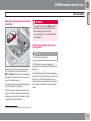
Arrows appear numbered and unnumbered and are used to illustrate a movement.
If there is no series of illustrations for step-bystep instructions then the different steps are
numbered with normal numbers.
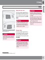
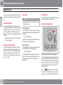
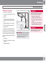
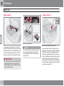
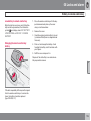
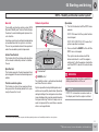
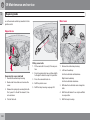
Position lists
Red circles containing a number are used
in overview images where different components are pointed out. The number
recurs in the position list featured in connection with the illustration that describes
the item.
Bulleted lists
A bulleted list is used when there is a list of
points in the owner's manual.
Example:
11
Introduction
Important information
• Coolant
• Engine oil
To be continued
`` This symbol is located furthest down to the
right when a section continues on the following
page.
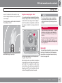
Recording data
Your vehicle contains a number of computers
whose function is to continuously check and
monitor the vehicle's operation and functionality. Some of the computers can record information during normal driving if they detect an
error. In addition, information is recorded in the
event of a crash or incident. Parts of the recorded information are required so that technicians can diagnose and rectify faults in the
vehicle during servicing and maintenance and
so that Volvo can fulfil legal requirements and
other regulations. In addition to this, the information is used for research purposes by Volvo
in order to continually develop quality and
safety, as the information can contribute to a
better understanding of the factors that cause
accidents and injuries. The information
includes details of the status and functionality
of various systems and modules in the vehicle
with regard to engine, throttle, steering and
brake systems, amongst other things. This
information may include details regarding the
12
way the driver drives the vehicle, such as vehicle speed, brake and accelerator pedal use,
steering wheel movement and whether or not
the driver and passengers have used their
seatbelts. For the reasons given this information may be stored in the vehicle's computers
for a certain length of time, but also as a result
of a collision or incident. This information may
be stored by Volvo as long as it can help to
further develop and further enhance safety and
quality and as long as there are legal requirements and other regulations that Volvo needs
to consider.
Volvo will not contribute to the above-described information being disclosed to third parties
without the vehicle owner's consent. However,
due to national legislation and regulations
Volvo may be required to disclose such information to authorities such as police authorities,
or others who may assert a legal right to have
access to it.
To be able to read and interpret the information
recorded by the computers in the vehicle
requires special technical equipment that
Volvo, and workshops that have entered into
agreements with Volvo, have access to. Volvo
is responsible that the information, which is
transferred to Volvo during servicing and maintenance, is stored and handled in a secure
manner and that the handling complies with
* Option/accessory, for more information, see Introduction.
applicable legal requirements. For further information - contact a Volvo dealer.
Accessories and extra equipment
The incorrect connection and installation of
accessories can negatively affect the car's
electrical system. Certain accessories only
function when their associated software is
installed in the car's computer system. We
therefore recommend that you always contact
an authorised Volvo workshop before installing
accessories which are connected to or affect
the electrical system.
Change of ownership for cars with
Volvo On Call *
Volvo On Call is a supplemental service that
consists of safety, security and comfort services. If the car has Volvo On Call and there is a
change of owner, it is very important that these
services are discontinued so that the former
owner cannot access the services in the car.
Contact the call centre by pressing the ON
CALL button in the car or contact an authorised Volvo workshop. See also "Changing the
security code" in the owner's manual for Volvo
On Call.
Introduction
Important information
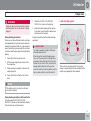
Information on the Internet
At www.volvocars.com there is further information concerning your car.
13
Introduction
Volvo and the environment
G000000
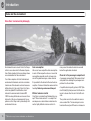
Volvo Cars' environmental philosophy
Environmental care is one of Volvo Car Corporation's core values which influence all operations. We also believe that our customers share
our consideration for the environment.
Your Volvo complies with strict international
environmental standards and is also manufactured in one of the cleanest and most resourceefficient plants in the world. Volvo Car Corporation has global ISO certification, which
includes the environmental standard ISO
14001 covering all factories and several of our
other units. We also set requirements for our
partners so that they work systematically with
environmental issues.
14
Fuel consumption
Volvo cars have competitive fuel consumption
in each of their respective classes. Lower fuel
consumption generally results in lower emission of the greenhouse gas, carbon dioxide.
It is possible for the driver to influence fuel consumption. For more information read under the
heading, Reducing environmental impact.
Efficient emission control
Your Volvo is manufactured following the concept "Clean inside and out" – a concept that
encompasses a clean interior environment as
well as highly efficient emission control. In
* Option/accessory, for more information, see Introduction.
many cases the exhaust emissions are well
below the applicable standards.
Clean air in the passenger compartment
A passenger compartment filter prevents dust
and pollen from entering the passenger compartment via the air intake.
A sophisticated air quality system, IAQS* (Interior Air Quality System) ensures that the incoming air is cleaner than the air in the traffic outside.
The system consists of an electronic sensor
and a carbon filter. The incoming air is monitored continuously and if there is an increase in
Introduction
Volvo and the environment
the level of certain unhealthy gases such as
carbon monoxide then the air intake is closed.
Such a situation may arise in heavy traffic,
queues and tunnels for example.
The entry of nitrous oxides, ground-level ozone
and hydrocarbons is prevented by the carbon
filter.
Interior
The interior of a Volvo is designed to be pleasant and comfortable, even for people with
contact allergies and for asthma sufferers.
Extreme attention has been given to choosing
environmentally-compatible materials.
Volvo workshops and the environment
Regular maintenance creates the conditions
for a long service life and low fuel consumption
for your car. In this way you contribute to a
cleaner environment. When Volvo's workshops
are entrusted with the service and maintenance of your car it becomes part of our system. We make clear demands regarding the
way in which our workshops are designed in
order to prevent spills and discharges into the
environment. Our workshop staff have the
knowledge and the tools required to guarantee
good environmental care.
Reducing environmental impact
You can easily help reduce environmental
impact - here are a few tips:
• Avoid letting the engine idle - switch off the
engine when stationary for longer periods.
Pay attention to local regulations.
• Drive economically - think ahead.
• Perform service and maintenance in
accordance with the owner's manual's
instructions - follow the Service and Warranty Booklet's recommended intervals.
Recycling
As a part of Volvo's environmental work, it is
important that the car is recycled in an environmentally sound manner. Almost all of the
car can be recycled. The last owner of the car
is therefore requested to contact a dealer for
referral to a certified/approved recycling
facility.
• If the car is equipped with an engine block
heater*, use it before starting from cold - it
improves starting capacity and reduces
wear in cold weather and the engine reaches normal operating temperature more
quickly, which lowers consumption and
reduces emissions.
The owner's manual and the
environment
The FSC symbol shows that the paper pulp in
this publication comes from FSC certified forests or other controlled sources.
• High speed increases consumption considerably due to increased wind resistance
- a doubling of speed increases wind resistance 4 times.
• Always dispose of environmentally hazardous waste, such as batteries and oils, in
an environmentally safe manner. Consult a
workshop in the event of uncertainty about
how this type of waste should be discarded
- an authorised Volvo workshop is recommended.
Following this advice can save money, the
planet's resources are saved, and the car's
durability is extended. For more information
and further advice, see the pages 140 and
282.
* Option/accessory, for more information, see Introduction.
15
Seatbelts.................................................................................................
Airbag system.........................................................................................
Airbags....................................................................................................
Activating/deactivating the airbag*.........................................................
Side airbags (SIPS bags)........................................................................
Inflatable Curtain (DMIC).........................................................................
WHIPS.....................................................................................................
Roll-Over Protection System (ROPS)......................................................
When the systems deploy.......................................................................
Crash mode............................................................................................
Child safety.............................................................................................
16
* Option/accessory, for more information, see Introduction.
18
21
22
24
26
28
29
31
32
34
35
SAFETY
01 Safety
Seatbelts
01
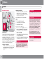
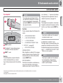
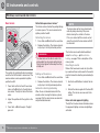
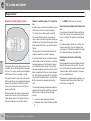
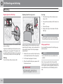
General information
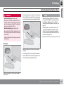
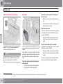
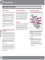
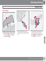
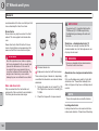
Releasing the seatbelt
Press the red lock button and then let the
seatbelt retract. If the seatbelt does not
retract fully, feed the seatbelt in by hand so
that it does not hang loose.
The seatbelt locks and cannot be withdrawn:
G020104
• if it is pulled out too quickly
• during braking and acceleration
• if the car leans heavily.
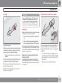
• do not use clips or anything else that can
prevent the seatbelt from fitting properly
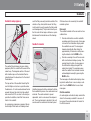
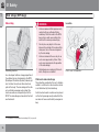
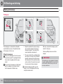
Tensioning the hip strap. The belt must be positioned low down.
• ensure that the seatbelt is not twisted or
Heavy braking can have serious consequences
if the seatbelts are not used. Ensure that all
passengers use their seatbelts. It is important
that the seatbelt lies against the body so it can
provide maximum protection. Do not lean the
backrest too far back. The seatbelt is designed
to protect in a normal seating position.
• the hip strap must be positioned low down
Putting on a seatbelt
18
Keep in mind the following
Pull the seatbelt out slowly and secure it by
pressing the buckle into the lock. A loud
"click" indicates that the seatbelt has
locked.
caught on anything
WARNING
Each seatbelt is designed for only one person.
WARNING
Never modify or repair the seatbelt yourself.
Volvo recommends that you contact an
authorised Volvo workshop. If the seatbelt
has been subjected to a major load, such as
in conjunction with a collision, the entire
seatbelt must be replaced. Some of the
seatbelt's protective properties may have
been lost even if the seatbelt does not
appear damaged. The seatbelt must also be
replaced if it shows signs of wear or damage. The new seatbelt must be typeapproved and designed for installation at
the same location as the replaced seatbelt.
(not over the abdomen)
• tension the hip strap over the lap by pulling
the diagonal shoulder belt as illustrated.
WARNING
The seatbelts and airbags interact. If a seatbelt is not used or is used incorrectly, this
may diminish the protection provided by the
airbag in the event of a collision.
WARNING
The rear seat is designed for a maximum of
two passengers.
01 Safety
Seatbelts
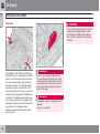
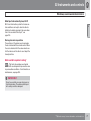
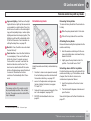
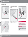
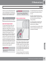
Seatbelts and pregnancy
such that they can easily maintain control of the
vehicle as they drive (which means that they
must be able to easily operate the foot pedals
and steering wheel). They should strive to position the seat with as large a distance as possible between their abdomen and the steering
wheel.
G020105
As a pregnancy progresses, pregnant drivers
should adjust their seats and steering wheel
Rear seat
The seatbelt reminder in the rear seat has two
subfunctions:
• Provides information on which seatbelts
• Provides a warning if one of the rear seatbelts is unfastened during a journey. This
warning takes the form of a message on
the information display along with the
audio/visual signal. The warning ceases
when the seatbelt is re-fastened or when
acknowledged manually by pressing the
READ button.
G029652
The lap section of the seatbelt should lay flat
over the thighs and as low as possible under
the abdomen. – It must never be allowed to ride
upward. Remove the slack from the seatbelt
and ensure that it fits as close to the body as
possible. In addition, check that there are no
twists in the seatbelt.
Child seats are not covered by the seatbelt
reminder system.
are being used in the rear seat. A message
is shown in the information display when
the seatbelts are used. The message is
cleared automatically after driving for
approximately 30 seconds or after pressing the indicator stalk's READ button.
Seatbelt reminder
The seatbelt should always be worn during
pregnancy. But it is crucial that it be worn in the
correct way. The diagonal section of the seatbelt should wrap over the shoulder then be
routed between the breasts and to the side of
the abdomen.
01
Unbelted occupants will be reminded to fasten
their seatbelts by means of an audio and visual
reminder. The audio reminder is speed
dependent, and in some cases time dependent. The visual reminder is located in the roof
console and the combined instrument panel.
The message on the information display showing which seatbelts are in use is always available. Press the READ button to see stored
messages.
Certain markets
An audio signal and indicator lamp remind the
driver if not wearing a seatbelt to use one. At
low speed, the audio reminder will sound for
the first 6 seconds.
``
19
01 Safety
01
Seatbelts
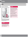
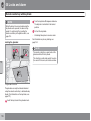
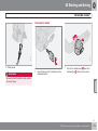
Seatbelt tensioner
Seatbelt guide
All the seatbelts are equipped with seatbelt
tensioners. A mechanism in the seatbelt tensioner tightens the seatbelt in the event of a
sufficiently violent collision. The seatbelt then
provides more effective restraint for occupants.
Never insert the tongue of the passenger's
seatbelt into the buckle on the driver's side.
Always insert the tongue of the seatbelt into
the buckle on the correct side. Do not make
any damages on seatbelts nor insert any
foreign objects into a buckle. The seatbelts
and buckles would then possibly not function as intended in the event of a collision.
There is a risk of serous injury.
G020106
WARNING
The seatbelt guide is fitted on both the driver's
seat and passenger seat.
The seatbelt guide is an aid for providing better
access to the seatbelt. When getting into and
out of the rear seat, remove the seatbelt from
the seatbelt guide and position it furthest back
on the seatbelt bar. Refit the seatbelt into the
seatbelt guide afterwards.
20
01 Safety
Airbag system
Warning symbol on the combined
instrument panel
01
As well as the warning symbol, a
message may appear on the display in appropriate cases. If the
warning symbol malfunctions, the
warning triangle illuminates and
the message SRS AIRBAG
SERVICE REQUIRED or SRS
AIRBAG SERVICE URGENT
appears in the display. Volvo recommends that you contact an authorised
Volvo workshop immediately.
WARNING
The warning symbol in the combined instrument panel illuminates when the remote control key is turned to key position I, II or III. The
symbol goes out after approx. 6 seconds provided the airbag system is fault-free.
If the warning symbol for the airbag system
remains illuminated or illuminates while driving, it means that the airbag system does
not have full functionality. The symbol indicates a fault in the seatbelt tensioner system, SIPS, SRS or the IC system. Volvo recommends that you contact an authorised
Volvo workshop immediately.
21
01 Safety
01
Airbags
Airbag system
WARNING
NOTE
Volvo recommends that you contact an
authorised Volvo workshop for repair.
Defective work in the airbag system could
cause malfunction and result in serious personal injury.
G020111
22
It is therefore possible that only one (or
none) of the airbags may inflate in a collision. The airbag system senses the force of
the collision on the car and adapts accordingly so that one or more airbags is
deployed.
The capacities of the airbags are also adapted to the collision force to which they are
subjected.
G020110
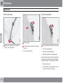
SRS system, left-hand drive
The system consists of airbags and sensors. A
sufficiently violent collision trips the sensors
and the airbag(s) are inflated with hot gas. To
cushion the impact, the airbag deflates when
compressed. When this occurs, smoke
escapes into the car. This is completely normal. The entire process, including inflation and
deflation of the airbag, takes place within
tenths of a second.
The sensors react differently depending on
the course of the collision and whether or
not the seatbelts on the driver's side and
passenger side are used.
SRS system, right-hand drive
01 Safety
Airbags
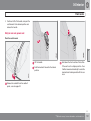
Airbag on the driver's side
The car has an airbag to supplement the protection afforded by the seatbelt on the driver's
side. It is folded up into the centre of the steering wheel. The steering wheel is marked SRS
AIRBAG.
G020113
WARNING
Location of the passenger airbag in left-hand drive
and right-hand drive cars.
WARNING
Do not put objects in front of or above the
instrument panel where the passenger airbag is located.
The seatbelts and airbags interact. If a seatbelt is not used or is used incorrectly, this
may diminish the protection provided by the
airbag in the event of a collision.
01
WARNING
Never place a child in a child seat or on a
booster cushion in the front seat if the airbag
is activated.1
Never allow anybody to stand or sit in front
of the front passenger seat. Children under
140 cm must never sit in the front passenger
seat if the airbag is activated.
Failure to follow the advice given above can
endanger life.
Passenger airbag
The car has an airbag to supplement the protection afforded by the seatbelt on the passenger side. It is folded up into a compartment
above the glovebox. The cover panel is marked
SRS AIRBAG.
WARNING
To minimise the risk of injury if the airbag
deploys, passengers must sit as upright as
possible with their feet on the floor and back
against the backrest. Seatbelts must be
secured.
1
For information on activated/deactivated airbag, see page 24.
23
01 Safety
01
Activating/deactivating the airbag*
Key switch off - PACOS*
General information
The airbag for the front passenger seat can be
deactivated if the car is equipped with a switch,
PACOS (Passenger Airbag Cut Off Switch). For
information on how to activate/deactivate, see
under the heading Activating/deactivating.
WARNING
Never place a child in a child seat or on a
booster cushion in the front seat if the airbag
is activated and the symbol
in the roof
console is illuminated. Failure to follow this
advice could endanger the life of the child.
WARNING
Key switch off/switch
The switch for the passenger airbag (PACOS)
is located on the passenger end of the instrument panel and is accessible when the passenger door is open, (see under the heading
below, Activating/deactivating).
Check that the switch is in the required position. Volvo recommends that the key blade is
used to change position.
Do not allow anyone to sit in the front passenger seat if the text message in the roof
panel indicates that the airbag is deactivated, and if the warning symbol for the airbag system is also displayed on the combined instrument panel. This indicates that
there has been a severe malfunction. Volvo
recommends that you visit an authorised
Volvo workshop as soon as possible.
For information on the key blade, see
page 121.
WARNING
Failure to follow the advice given above can
endanger life.
WARNING
If the car is equipped with a front passenger
airbag, but does not have a switch (PACOS),
then the airbag will always be activated.
24
Activating/deactivating
* Option/accessory, for more information, see Introduction.
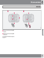
Switch location
The airbag is activated. With the switch in
this position, children taller than 140 cm
can sit in the front passenger seat, but
never children in a child seat or on a
booster cushion.
The airbag is deactivated. With the switch
in this position, children in a child seat or
on a booster cushion can sit in the front
passenger seat, but never persons taller
than 140 cm.
01 Safety
Activating/deactivating the airbag*
A text message and a symbol in the roof panel
indicate that the airbag for the front passenger
seat is deactivated (see preceding illustration).
WARNING
Activated airbag (passenger seat):
Never place a child in a child seat or on a
booster cushion on the front passenger seat
when the airbag is activated. This applies to
everyone shorter than 140 cm.
01
NOTE
When the remote control key is turned to
key position II or III the warning symbol for
the airbag is displayed on the combined
instrument panel for approx. 6 seconds, see
page 21.
Following which, the indicator in the roof
console is illuminated showing the correct
status for the front passenger seat airbag.
For more information about the different key
positions, see page 150.
Deactivated airbag (passenger seat):
No one taller than 140 cm should ever sit in
the front passenger seat when the airbag is
deactivated.
Failure to follow the advice given above can
endanger life.
G018344
Messages
Indicator showing that the passenger airbag is
activated.
G018346
A warning symbol in the roof panel indicates
that the airbag for the front passenger seat is
activated (see preceding illustration).
Indicator showing that the passenger airbag is
deactivated.
* Option/accessory, for more information, see Introduction.
25
01 Safety
Side airbags (SIPS bags)
Side airbag
WARNING
Volvo recommends that repairs are only
carried out by an authorised Volvo
workshop. Defective work in the SIPSbag system could cause malfunction
and result in serious personal injury.
•
Do not place any objects in the area
between the outside of the seat and the
door panel, since this area is required
by the side airbag.
•
Volvo recommends the use only of car
seat covers approved by Volvo. Other
seat covers may impede the operation
of the side airbags.
•
Side airbags are a supplement the seatbelts. Always use a seatbelt.
G020118
•
Side airbag locations.
In a side impact collision a large proportion of
the collision force is transferred by the SIPS
(Side Impact Protection System) to beams, pillars, the floor, the roof and other structural
parts of the body. The side airbags at the driver's and front passenger seats protect the
chest area and are an important part of the
SIPS. The side airbags are located in the front
seat backrests.
1
26
Child seats and side airbags
The protection provided by the car to children
seated in a child seat or on a booster cushion
is not diminished by the side airbag.
A child seat or booster cushion can be placed
on the front passenger seat provided that the
car does not have an activated1 passenger airbag.
For information on activated/deactivated airbag (SRS), see page 24.
Location
G025315
01
Driver's seat, left-hand drive.
01 Safety
01
G025316
Side airbags (SIPS bags)
Front passenger seat, left-hand drive.
The SIPS bag system consists of side airbags
and sensors. A sufficiently violent collision trips
the sensors and the side airbags are inflated.
The airbag inflates between the occupant and
the door panel and thereby cushions the initial
impact. The airbag deflates when compressed
by the collision. The side airbag is normally only
deployed on the side of the collision.
27
01 Safety
01
Inflatable Curtain (DMIC)
Properties
WARNING
G025424
G025425
There is a risk of personal injury if the driver
or passenger is leaning against the door
panel when the inflatable curtain deploys.
This could also compromise the intended
protection.
The inflatable curtain, DMIC (Door Mounted
Inflatable Curtain), is a supplement to the SIPS
system. It is fitted along the inside of the driver's and passenger doors and protects both
front seat occupants. The inflatable curtain is
activated by sensors in the event of a sufficiently violent collision or if the car is at risk of
overturning. When deployed, the inflatable curtain inflates. The inflatable curtain helps to prevent the driver and front seat passenger from
striking their heads on the inside of the car during a collision. The inflatable curtain is
deployed irrespective of whether the roof is
open or closed.
28
WARNING
Do not screw or install anything onto the
car's headlining or side panels. This could
compromise the intended protection. Volvo
recommends that you only ever use Volvo
genuine parts that are approved for placement in these areas.
WARNING
The inflatable curtain is a supplement to the
seatbelts.
Always use a seatbelt.
01 Safety
WHIPS
01
G020347
Protection against whiplash injury – WHIPS
The whiplash protection system (WHIPS) consists of energy absorbing backrests and specially designed head restraints for the front
seats. The system is actuated by a rear-end
collision, where the angle and speed of the collision, and the nature of the colliding vehicle all
have an influence.
Properties of the seat
When the WHIPS system is deployed, the front
seat backrests are lowered backward to alter
the seating position of the driver and front seat
passenger. This reduces the risk of whiplash
injury.
The WHIPS system is a supplement to the
seatbelts. Always use a seatbelt.
The protection provided by the car to children
seated in a child seat or on a booster cushion
is not diminished by the WHIPS system.
Correct seating position
WARNING
WARNING
WHIPS system and child seats/booster
cushions
Never modify or repair the seat or WHIPS
system yourself. Volvo recommends that
you contact an authorised Volvo workshop.
For the best possible protection, the driver and
front seat passenger should sit in the centre of
the seat with as little space as possible
between the head and the head restraint.
``
29
01 Safety
01
WHIPS
Do not obstruct the WHIPS system
WARNING
If a seat has been subjected to extreme
forces, such as due to a rear-end collision,
the WHIPS system must be checked. Volvo
recommends that it is checked by an
authorised Volvo workshop.
G020125
Part of the WHIPS system's protective
capacity may have been lost even if the
seats appear to be undamaged.
Do not leave any objects on the floor behind the
driver's seat/passenger seat that may prevent the
WHIPS system from functioning.
WARNING
Do not squeeze rigid objects between the
rear seat cushion and the front seat backrest. Make sure you do not to obstruct the
function of the WHIPS system.
30
Volvo recommends that you contact an
authorised Volvo workshop to have the system checked even after a minor rear-end
collision.
01 Safety
Roll-Over Protection System (ROPS)
ROPS function
01
WARNING
Do not carry out any work on the ROPS system.
G020797
Do not place any objects on the ROPS system or behind the passengers' head
restraints.
Roll bars in raised position.
The ROPS system consists of strong roll bars
which are located behind the passengers'
head restraints, as well as sensors. In the event
of a situation where the car is at risk of overturning, or in the event of a sufficiently violent
collision from behind, the sensors detect this
and the roll bars rise up behind the passengers'
heads. The roll bars are deployed irrespective
of whether the roof is open or closed.
Volvo recommends that you always contact an
authorised Volvo workshop if the ROPS system
has deployed.
31
01 Safety
When the systems deploy
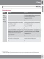
01
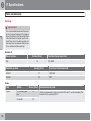
Activating the systems
A
System
Triggered
Seatbelt tensioner, front seat
In a frontal collision and/or side-impact accident and/or rear-end collision and/or
overturning.
Seatbelt tensioner, rear seat
In a frontal collision and/or side-impact accident and/or overturning.
Airbags
In a frontal collisionA
Side airbags (SIPS)
In a side-impact accidentA
Inflatable Curtain DMIC
In a side-impact accident and/or overturningA
Whiplash protection WHIPS
In a rear-end collision.
Roll-Over Protection System (ROPS)
In the event of overturning and/or collision from behind.
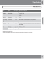
The bodywork of the car could be greatly deformed in a collision without airbag deployment. A number of factors such as the rigidity and weight of the object hit, the speed of the car, the angle of
the collision etc. affects how the different safety systems of the car are activated.
If the airbags have been deployed, the following is recommended:
• Recovering the car. Volvo recommends
that you have it conveyed to an authorised
Volvo workshop. Do not drive with
deployed airbags.
• Volvo recommends that you engage an
authorised Volvo workshop to handle the
replacement of components in the car's
safety systems.
• Always contact a doctor.
32
NOTE
The airbag, SIPS, DMIC, belt tensioner and
ROPS systems are deployed only once during a collision.
WARNING
The airbag system's control module is
located in the centre console. If the centre
console is drenched with water or other liquid, disconnect the battery cables. Do not
attempt to start the car since the airbags
may deploy. Recovering the car. Volvo recommends that you have it conveyed to an
authorised Volvo workshop.
01 Safety
When the systems deploy
01
WARNING
Never drive with deployed airbags. They
can make steering difficult. Other safety
systems may also be damaged. The smoke
and dust created when the airbags are
deployed can cause skin and eye irritation/
injury after intensive exposure. In case of
irritation, wash with cold water. The rapid
deployment sequence and airbag fabric
may cause friction and skin burns.
33
01 Safety
01
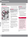
Crash mode
Driving after a collision
Firstly, remove the remote control key and then
reinsert it. The car's electronics will then try to
reset themselves to normal mode. Then try to
start the car. If CRASH MODE SEE
MANUAL is still shown on the display then the
car must not be driven or towed. Even if the car
appears to be driveable, hidden damage may
make the car impossible to control once moving.
G029042
Moving the car
If NORMAL MODE is shown after CRASH
MODE SEE MANUAL has been reset, the car
If the car is involved in a collision, the text
CRASH MODE SEE MANUAL may appear on
the information display. This means that the car
has reduced functionality. Crash mode is a
protective state that is enforced when the collision may have damaged any of the car's vital
functions, such as the fuel lines, sensors for
one of the safety systems, or the brake system.
Attempting to start the car
First, check that no fuel is leaking from the car.
There must be no smell of fuel either.
If everything seems normal and you have
checked for indications of fuel leakage, you
may attempt to start the car.
34
can be moved carefully out of a dangerous
position. Do not move the car further than necessary.
WARNING
Never attempt to repair your car or reset the
electronics yourself if the car has been in
crash mode. This could result in personal
injury or the car not functioning as normal.
Volvo recommends that you always engage
an authorised Volvo workshop to check and
restore the car to NORMAL MODE after
CRASH MODE SEE MANUAL has been
displayed.
WARNING
Never, under any circumstances, attempt to
restart the car if it smells of fuel when the
CRASH MODE SEE MANUAL message is
displayed. Leave the car at once.
WARNING
If the car is in crash mode it must not be
towed. It must be transported from its location. Volvo recommends that you have it
conveyed to an authorised Volvo workshop.
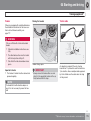
01 Safety
Child safety
Children should sit comfortably and
safely
Volvo recommends that children travel in rearfacing child seats until as late an age as possible, at least until 3-4 years of age, and then
front-facing booster cushions/child seats until
up to 10 years of age.
NOTE
In the event of questions when fitting child
safety products, contact the manufacturer
for clearer instructions.
Child seats
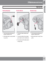
Location of child seats
You may place:
• a child seat/booster cushion on the front
passenger seat, provided the passenger
airbag is not activated1.
NOTE
• one or more child seats/booster cushions
Regulations regarding the placement of
children in cars vary from country to country. Check what does apply.
in the rear seat.
Always fit child seats/booster cushions in the
rear seat if the passenger airbag is activated. A
child in the front passenger seat could suffer
serious injury if the airbag deploys.
G020128
Children of all ages and sizes must always sit
correctly secured in the car. Never allow a child
to sit on the knee of a passenger.
1
Do not attach the straps for the child seat to
the horizontal adjustment bar, springs, rails or
beams under the seat. Sharp edges can damage the straps.
Look in the installation instructions for the child
seat for the correct fitting.
The position of a child in the car and the choice
of equipment are dictated by the child's weight
and size, for more information, see page 37.
Volvo has child safety equipment (child seats,
booster cushions & attachment devices) which
is designed for your particular car. Using Volvo's child safety equipment provides you with
optimum conditions for your child to travel
safely in the car. Furthermore, the child safety
equipment fits and is easy to use.
01
Child seats and airbags are not compatible.
NOTE
When using child safety products it is
important to read the installation instructions included with the product.
For information on activated/deactivated airbag, see page 24.
``
35
01 Safety
Child safety
01
WARNING
Never place a child in a child seat or on a
booster cushion in the front seat if the airbag
is activated2.
No one shorter than 140 cm should ever sit
in the front passenger seat if the airbag is
activated.
Failure to follow the advice given above can
endanger life.
2
36
WARNING
Label Airbag
Booster cushions/child seats with steel
braces or some other design that could rest
on the seatbelt buckle's opening button
must not be used, as they could cause the
seatbelt buckle to open accidentally.
Do not allow the upper section of the child
seat to rest against the windscreen.
For information on activating/deactivating the airbag (SRS), see page 24.
Label fitted on the end face of the instrument panel
on the passenger side, see the illustration on page
24.
01 Safety
Child safety
01
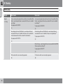
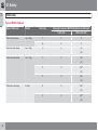
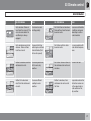
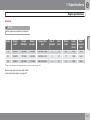
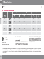
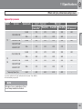
Recommended child seats3
Weight
Front seatA
Group 0
Rear seat
Volvo infant seat (Volvo Infant Seat) - rear-facing child seat,
secured with the ISOFIX fixture system.
max. 10 kg
Type approval: E1 04301146
Group 0+
(L)
max. 13 kg
Volvo infant seat (Volvo Infant Seat) - rear-facing child seat,
secured with the car's seatbelt.
Volvo infant seat (Volvo Infant Seat) - rear-facing child seat,
secured with the car's seatbelt.
Type approval: E1 04301146
Type approval: E1 04301146
(U)
(U)
Rear-facing child seat (Child Seat) - rear-facing child seat,
secured with the car's seatbelt and straps. Use a protective
cushion between the child seat and the dashboard.
Rear-facing child seat (Child Seat) - rear-facing child seat,
secured with the car's seatbelt, straps and support legs.
Type approval: E5 03135
Type approval: E5 03135
(L)
(L)
3
Child seats which are universally approved.
Child seats which are universally approved.
(U)
(U)
With regard to other child seats the car should be included in the manufacturer's enclosed list of vehicles or be universally approved in accordance with the ECE R44 legal requirement.
``
37
01 Safety
01
Child safety
Weight
Front seatA
Rear seat
Group 1
Volvo rear-facing/turnable child seat (Volvo Convertible Child
Seat) - rear-facing child seat, secured with the car's seatbelt
and straps.
Volvo rear-facing/turnable child seat (Volvo Convertible Child
Seat) - rear-facing child seat, secured with the car's seatbelt
and straps.B
Type approval: E5 04192
Type approval: E5 04192
(L)
(L)
Rear-facing child seat (Child Seat) - rear-facing child seat,
secured with the car's seatbelt and straps. Use a protective
cushion between the child seat and the dashboard.
Rear-facing child seat (Child Seat) - rear-facing child seat,
secured with the car's seatbelt, straps and support legs.B
9 – 18 kg
Type approval: E5 03135
Type approval: E5 03135
(L)
(L)
Britax Fixway – rear-facing child seat, secured with the ISOFIX
fixture system and straps.B
Type approval: E5 03171
(L)
38
Child seats which are universally approved.
Child seats which are universally approved.
(U)
(U)
01 Safety
Child safety
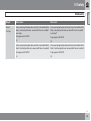
Weight
Front seatA
Rear seat
Group 2
Volvo rear-facing/turnable child seat (Volvo Convertible Child
Seat) - rear-facing child seat, secured with the car's seatbelt
and straps.
Volvo rear-facing/turnable child seat (Volvo Convertible Child
Seat) - rear-facing child seat, secured with the car's seatbelt
and strapsB
Type approval: E5 04192
Type approval: E5 04192
(L)
(L)
Volvo rear-facing/turnable child seat (Volvo Convertible Child
Seat) - front-facing child seat, secured with the car's seatbelt.
Volvo rear-facing/turnable child seat (Volvo Convertible Child
Seat) - front-facing child seat, secured with the car's seatbelt.
Type approval: E5 04191
Type approval: E5 04191
(L)
(L)
15-25 kg
01
``
39
01 Safety
Child safety
01
Weight
Front seatA
Rear seat
Group 2/3
Volvo booster seat with backrest (Volvo Booster Seat with
backrest).
Volvo booster seat with backrest (Volvo Booster Seat with
backrest).
Type approval: E1 04301169
Type approval: E1 04301169
(UF)
(UF)
Booster cushion with and without backrest (Booster Cushion
with and without backrest).
Booster cushion with and without backrest (Booster Cushion
with and without backrest).
Type approval: E5 03139
Type approval: E5 03139
(UF)
(UF)
15 – 36 kg
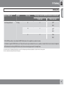
L: Suitable for specific child seats. These child seats may be intended for use in a special car model, limited or semi-universal categories.
U: Suitable for universally approved child seats in this weight class.
UF: Suitable for front-facing universally approved child seats in this weight class.
A
B
For information on activated/deactivated airbag, see page 24.
To install a rear-facing child seat in the rear seat, Volvo recommends that you contact an authorised Volvo dealer to have the mounting points installed.
WARNING
Never place a child in a child seat or on a
booster cushion in the front seat if the airbag
is activated4.
No one shorter than 140 cm should ever sit
in the front passenger seat if the airbag is
activated.
Failure to follow the advice given above can
endanger life.
4
40
For information on activating/deactivating the airbag (SRS), see page 24.
01 Safety
Child safety
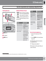
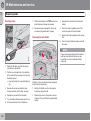
ISOFIX fixture system for child seats
Size classes
Child seats are in different sizes – cars are in
different sizes. This means that not all child
seats are suitable for all seats in all car models.
Consequently, there is a size classification for
child seats using the ISOFIX fixture system in
order to assist users in choosing the correct
child seat (see the following table).
Size
class
Description
B
Reduced size (alt. 1), frontfacing child seat
B1
Reduced size (alt.2), frontfacing child seat
The location of the mounting points is indicated
by symbols in the backrest upholstery (see
illustration above).
C
Full size, rear-facing child
seat
Press the seat cushion down to access the
mounting points.
D
Reduced size, rear-facing
child seat
E
Rear-facing infant seat
G020798
Full size, front-facing child
seat
Always follow the manufacturer's installation
instructions when connecting a child seat to
the ISOFIX mounting points.
Description
F
Transverse infant seat, lefthand
G
Transverse infant seat, righthand
WARNING
Never place a child in the passenger seat if
the car is equipped with an activated airbag.
A
Mounting points for the ISOFIX fixture system
are concealed behind the lower section of the
rear seat backrest, in the outer seats.
Size
class
01
NOTE
If an ISOFIX child seat has no size classification then the car model must be included
on the child seat's vehicle list.
NOTE
Volvo recommends that you contact an
authorised Volvo dealer for recommendations about which ISOFIX child seats Volvo
recommends.
``
41
01 Safety
01
Child safety
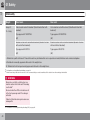
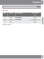
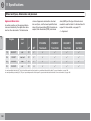
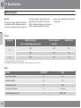
Types of ISOFIX child seat
Type of child seat
Infant seat transverse
Infant seat, rear-facing
Weight
max. 10 kg
max. 10 kg
Size class
Passenger seats for ISOFIX installation of child seats
Front seat
Outer rear seat
F
X
X
G
X
X
E
X
OK
(IL)
Infant seat, rear-facing
max. 13 kg
E
X
OK
(IL)
D
X
OKA
(IL)
C
X
OKA
(IL)
Child seat, rear-facing
9-18 kg
D
X
OKA
(IL)
C
X
OKA
(IL)
42
01 Safety
Child safety
Type of child seat
Front-facing child seat
Weight
9-18 kg
Size class
B
01
Passenger seats for ISOFIX installation of child seats
Front seat
Outer rear seat
X
OKB
(IUF)
B1
X
OKB
(IUF)
A
X
OKB
(IUF)
X: The ISOFIX position is not suitable for ISOFIX child seats in this weight class and/or size class.
IL: Suitable for specific ISOFIX child seats. These child seats may be intended for use in a special car model, limited or semi-universal categories.
IUF: Suitable for front-facing ISOFIX child seats that are universally approved in this weight class.
A
B
In order to be able to fit the infant/child seat in the rear seat, the front passenger seat has been adjusted to a location in front of centre position.
Volvo recommends rear-facing child seats for this group.
43
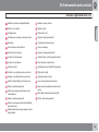
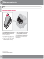
Overview, left-hand drive cars................................................................
Overview, right-hand drive cars..............................................................
Driver's door control panel.....................................................................
Combined instrument panel....................................................................
Indicator and warning symbols...............................................................
Information display..................................................................................
Electrical socket......................................................................................
Lighting panel..........................................................................................
Left-hand stalk switch.............................................................................
Right-hand stalk switch..........................................................................
Cruise control*........................................................................................
Keypad in the steering wheel*................................................................
Steering wheel adjustment, hazard warning flashers.............................
Parking brake..........................................................................................
Power windows.......................................................................................
Windows, rearview and door mirrors......................................................
Personal preferences..............................................................................
46
48
50
51
52
56
58
59
62
65
67
69
70
71
72
74
78
HomeLink *............................................................................................ 81
44
* Option/accessory, for more information, see Introduction.
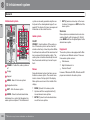
INSTRUMENTS AND CONTROLS
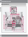
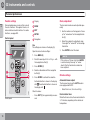
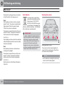
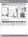
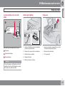
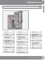
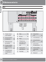
02 Instruments and controls
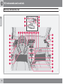
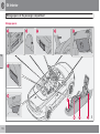
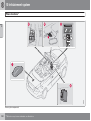
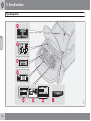
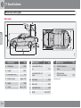
Overview, left-hand drive cars
20
18
02
22
17
21
16
10
9
8
7
6
5
11
12
13 14 15
19
8
26
8
23 24
25
8
9
7
27
28
29
4
3
2
1
3
31
30
32
34
46
G028206
33
02 Instruments and controls
Overview, left-hand drive cars
Steering wheel adjustment
Switch, optional equipment
Opening handle, bonnet
Switch, passenger compartment automatic lighting
Control panel, windows and door mirrors
Direction indicators, main beam, trip computer
Lighting panel and fuel filler flap opener
Door handle and lock button.
Indicator lamp, locking
Air vents, dashboard
Air vent for side window
Cruise control
Horn and airbags
Switch, optional equipment
Switch, passenger compartment lighting,
right-hand side
Display, car settings/audio system etc.
Controls, car settings/audio system etc.
Climate control
Indicator lamp, hazard warning flashers
Door handle and lock button
Glovebox
Combined instrument panel
Gear lever (manual)/gear selector (automatic)
Keypad for infotainment system
Electrical socket and cigarette lighter
Windscreen wipers and washer, headlamp
washers
Switch, roof control
Ignition switch
Rearview mirror, interior
02
Parking brake
Blind Spot Information System, BLIS
Switch, optional equipment
Seatbelt reminder and passenger seat airbag indicator
Switch, interior lighting, left-hand side
47
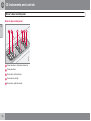
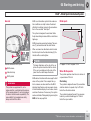
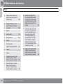
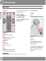
02 Instruments and controls
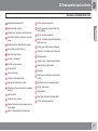
Overview, right-hand drive cars
15
17
02
13
18
14
19
16
10
11
12
9
26
9
20 21 22 23 24 25
9
8
8
7
9
6
7
5
27
32
28
4
29
2
4
3
1
30
31
34
48
G019491
33
02 Instruments and controls
Overview, right-hand drive cars
Electrical socket and cigarette lighter
Rearview mirror, interior
Switch, roof control
Ignition switch
Parking brake
Stalk switch, left
Control panel, windows and door mirrors
Keypad, steering wheel, left
Glovebox
Combined instrument panel
Door handle and lock button
Horn and airbags
Indicator lamp, locking
Keypad, steering wheel, right
Air vent for side window
Indicator lamp, hazard warning flashers
Air vents in dashboard
Door handle and lock button
Climate control
Lighting panel and fuel filler flap opener
Controls, car settings/audio system etc.
Stalk switch, right
Display, car settings/audio system etc.
Opening handle, bonnet
Switch, interior lighting, left-hand side
Lever, steering wheel adjustment
Switch, optional equipment
Gear lever (manual)/gear selector (automatic)
Switch, passenger compartment automatic lighting
Switch, optional equipment
02
Blind Spot Information System, BLIS
Switch, optional equipment
Switch, passenger compartment lighting,
right-hand side
Seatbelt reminder and passenger seat airbag indicator
49
02 Instruments and controls
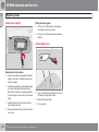
Driver's door control panel
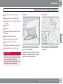
Driver's door control panel
02
Power windows, all windows down/up
Power windows
Door mirror, left-hand side
Door mirrors, setting
Door mirror, right-hand side
50
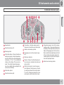
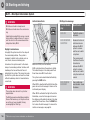
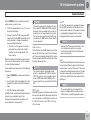
02 Instruments and controls
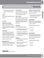
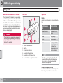
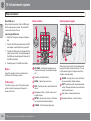
Combined instrument panel
02
Speedometer.
Direction indicators, left.
Warning symbol.
Information display – Shows information or
warning messages, outside temperature
and clock. When the outside temperature
is between +2 °C to -5 °C a snowflake illuminates on the display. This warns of icy
roads. The outside temperature gauge
may show a slightly high reading after the
car has been stationary.
Information symbol.
Direction indicator, right.
Tachometer – Indicates engine speed in
thousands of revolutions per minute (rpm).
Indicator and warning symbols.
Fuel gauge, see also trip computer, pag
e 63.
Main beam indicator.
Display – Display for automatic gear position, rain sensor, odometer, trip meter and
cruise control.
Temperature gauge - Used for the engine
cooling system. A message will appear on
the display if the temperature becomes too
high and the gauge goes into the red zone.
Bear in mind that extra lights placed in front
of the air intake, for example, reduce the
cooling capacity at high outside temperatures and high engine loads.
Indicator and warning symbols.
Button for trip meter – Used to measure
short distances. Short presses on the button switches between the two trip meters
T1 and T2. A long press (more than 2 seconds) resets an active trip meter to zero.
51
02 Instruments and controls
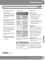
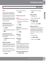
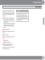
Indicator and warning symbols
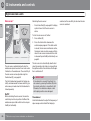
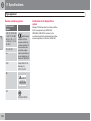
Functionality check, symbols
02
All indicator and warning symbols1 illuminate
when the remote control key is turned to position II before starting. This is to check that the
symbols are working. When the engine starts,
all the symbols should go out except the handbrake symbol, which only goes out when the
brake is disengaged.
Symbols in the centre of the instrument
panel
G030755
The red warning symbol illuminates when a fault has been indicated which could affect the safety
and/or driveability of the car. An
explanatory text is shown on the
information display at the same time. The symbol remains visible until the fault has been rectified but the text message can be cleared with
the READ button, see page 56. The warning
symbol can also illuminate in conjunction with
other symbols.
52
1. Stop in a safe manner. Do not drive the car
further.
2. Read the information on the information
display. Implement the action in accordance with the message in the display. Clear
the message using READ.
If the engine does not start within
five seconds, all symbols extinguish except the symbols for a
fault in the car's emissions system
and for low oil pressure. Certain
symbols may have no function,
depending on the car's specifications.
1
When the symbol illuminates:
For certain engine variants, the symbol for low oil pressure is not used. Warnings are given via display text, see page 56.
The yellow information symbol illuminates and a text appears on the
information display. The message
text is cleared using the READ button, see page 56, or disappears
automatically after a period of time (time
depending on which function is indicated).
The yellow information symbol can also illuminate in conjunction with other symbols.
NOTE
When a service message is shown, the symbol and message are cleared using the
READ button, or disappear automatically
after a time.
02 Instruments and controls
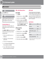
Indicator and warning symbols
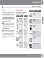
Indicator symbols – left-hand side
Emissions system
Stability system DSTC*
If the symbol illuminates then it
may be due to a fault in the car's
emissions system. Volvo recommends that you seek assistance
from an authorised Volvo workshop for inspection.
G029048
ABS fault
Fault in car's emissions system
If this symbol illuminates then the
system is not working. The car's
regular brake system continues to
work, but without the ABS function.
1. Stop the car in a safe place and turn off the
engine.
For information on the system's
functions and symbols, see
page 161.
02
Engine preheater (diesel)
This symbol illuminates during
engine preheating. Preheating
occurs when the temperature is
below -2 °C. The car can be started
once the symbol goes out.
Low level in fuel tank
When the symbol illuminates the
level in the fuel tank is low, refuel
as soon as possible.
2. Restart the engine.
ABS fault
Rear fog lamp
Stability system DSTC
No function
Engine preheater (diesel)
3. Drive to a workshop to have the ABS system checked if the symbol remains lit.
Volvo recommends that you seek assistance from an authorised Volvo workshop.
Rear fog lamp
This symbol is lit when the rear fog
lamp is on.
Low level in fuel tank
``
* Option/accessory, for more information, see Introduction.
53
02 Instruments and controls
Indicator and warning symbols
Indicator symbols – right-hand side
Indicator symbol for trailer
This symbol flashes when the
direction indicators are used and
the trailer is connected. If the symbol does not flash then one of the
lamps on the trailer or the car is
02
faulty.
Parking brake applied
G029049
The symbol illuminates when the
parking brake is applied. Always
pull the parking brake lever to the
end position.
Indicator symbol for trailer
NOTE
The symbol illuminates irrespective of how
hard the parking brake is applied.
Parking brake applied
Airbags – SRS
Low oil pressure
Seatbelt reminder
Alternator not charging
Fault in brake system
2
54
Airbags – SRS
If this symbol remains illuminated
or illuminates while driving, it
means a fault has been detected in
the seatbelt buckle, SRS, SIPS or
IC system. Volvo recommends that
drive directly to an authorised Volvo workshop
for inspection.
For certain engine variants, the symbol for low oil pressure is not used. Warnings are given via display text, see page 56.
Low oil pressure2
If this symbol illuminates during
driving then the engine's oil pressure is too low. Stop the engine
immediately and check the engine
oil level, top up if necessary. If the
symbol illuminates and the oil level is normal
Volvo recommends that you contact an authorised Volvo workshop.
Seatbelt reminder
This symbol illuminates if someone
in a front seat has not put on their
seatbelt or if someone in a rear
seat has taken off their seatbelt.
Alternator not charging
If this symbol illuminates while
driving, a fault has occurred in the
electrical system. Volvo recommends that you visit an authorised
Volvo workshop.
Fault in brake system
If this symbol illuminates, the brake
fluid level may be too low.
02 Instruments and controls
Indicator and warning symbols
Stop the car in a safe place and check the
level in the brake fluid reservoir, see
page 219. If the reservoir level is below
MIN then the car should not be driven further. Volvo recommends that the car is
transported to an authorised Volvo workshop to have the brake system checked.
If the BRAKE and ABS symbols
illuminate at the same time, there
may be a fault in the brake force
distribution system.
have the brake system checked. Volvo recommends that you seek assistance from
an authorised Volvo workshop.
6. If the level in the reservoir is below MIN
then the car should not be driven any further. Have the car transported to a workshop to have the brake system checked.
Volvo recommends that you seek assistance from an authorised Volvo workshop.
WARNING
High speed
If the car is moving faster than
10 km/h, the symbol illuminates
and one of the texts indicated in
the preceding paragraph appears
on the display.
02
Boot lid reminder
If the boot lid is open, this information symbol will illuminate and
BOOT LID OPEN will appear on
the display.
If the BRAKE and ABS symbols are lit at the
same time, there is a risk that the rear end
will skid during heavy braking.
1. Stop the car in a safe place and turn off the
engine.
2. Restart the engine.
3. If both symbols extinguish, continue driving.
4. If the symbols remain illuminated, check
the level in the brake fluid reservoir, see
page 219.
5. If the brake fluid level is normal but the
symbols are still illuminated, the car can be
driven, with great care, to a workshop to
3
Reminder – doors not closed
If one of the doors, the bonnet3 or the boot lid
is not properly closed, the driver will be
reminded of this.
Low speed
If the car moves at a speed less
than 5 km/h, the information symbol illuminates and DRIVER
DOOR OPEN, PASSENGER
DOOR OPEN or BONNET OPEN
is shown on the display. Stop the car safely as
soon as possible and close the door or bonnet.
Only cars with alarm.
55
02 Instruments and controls
Information display
Messages
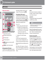
G029050
02
When a warning or indicator symbol illuminates
the information display shows a supplementary message.
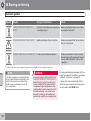
Specification
Message
Specification
STOP SAFELYA
Stop the car in a safe
manner and turn off
the engine. Serious
risk of damage.
TIME FOR REGULAR SERVICE
SERVICE
URGENTA
Volvo recommends
that an authorised
Volvo workshop
checks the car
immediately.
SEE MANUALA
Read the Owner's
Manual.
Time for regular
service. Volvo recommends that an
authorised Volvo
workshop carries
out the service. The
timing is determined
by the number of kilometres driven,
number of months
since the last service, engine running
time and oil grade.
SERVICE
REQUIREDA
Volvo recommends
that an authorised
Volvo workshop
checks the car as
soon as possible.
SERVICE OVERDUE
HIGH ENGINE
TEMP STOP
ENGINE
Stop the car in a safe
manner and turn off
the engine. Serious
risk of damage.
If the service intervals are not followed
then the warranty
does not cover any
damaged parts.
Volvo recommends
that an authorised
Volvo workshop carries out the service.
BOOK TIME FOR
SERVICE
Time to book regular
service. Volvo recommends that an
authorised Volvo
workshop carries
out the service.
TRANSMISSION
OIL CHANGE NEEDED
Volvo recommends
that an authorised
Volvo workshop
checks the car as
soon as possible.
Press the READ button (1).
Switch between messages with the READ button. Fault messages are stored in the memory
until the fault is rectified.
NOTE
If a warning message appears while you are
using the trip computer, the message must
be read (press READ) before the previous
activity can be resumed.
56
Message
02 Instruments and controls
Information display
Message
Specification
Message
Specification
REMINDER
CHECK OIL LEVEL
Check the oil level.
The message is
shown every 10
000 km (certain
engine variants). For
information on
checking the oil
level, see page 215.
TRANSMISSION
PERFORMANCE
LOW
The gearbox cannot
handle full capacity.
Drive carefully until
the message clears,
see page 157.
SOOT FILTER
FULL SEE OWNER
MANUAL
Diesel particle filter
requires regeneration, see page 144.
DSTC SPIN CONTROL OFF
The function of the
stability and traction
control system is
reduced, see
page 162 for more
variants.
02
If shown repeatedly
then Volvo recommends that an
authorised Volvo
workshop is contacted.
A
TRANSMISSION
OIL TEMP HIGH
Drive more smoothly
or stop the car in a
safe manner. Disengage the gear and
run the engine at
idling speed until the
message clears.
TRANSM OIL
TEMP STOP
SAFELY
Critical fault. Stop
the car immediately
in a safe manner.
Volvo recommends
that an authorised
Volvo workshop is
contacted.
Part of message, shown together with information on where
the problem has arisen.
57
02 Instruments and controls
Electrical socket
12 V electrical socket
WARNING
Always leave the plug in the socket when
the socket is not in use.
02
G019621
NOTE
Electrical socket and cigarette lighter.
The electrical socket can be used for various
accessories designed for 12 V, e.g. TV screens,
music players and mobile phones. For the
socket to supply current, the remote control
key must be in at least position I, see
page 150.
IMPORTANT
Max. socket is 10 A (120 W).
58
Optional equipment and accessories - e.g.
TV screens, music players and mobile
phones - which are connected to one of the
passenger compartment's 12V electrical
sockets, could be activated by the climate
control system, even when the remote control key has been removed or when the car
is locked, for example, when the parking
heater is activated at a preset time.
For this reason remove the plugs from the
electrical sockets for optional equipment or
accessories when not in use because the
battery could be drained in the event of such
an occurrence!
Cigarette lighter*
Activate the lighter by pushing in the button.
The button pops out when the lighter is hot. Pull
out the lighter and light a cigarette on the
heated coils.
* Option/accessory, for more information, see Introduction.
02 Instruments and controls
Lighting panel
General
Position
Position/parking lamps
Specification
Position/parking lamps can be switched on
irrespective of remote control key position.
Automatic/deactivated dipped
beam. Only main beam flash.
Position/parking lamps
When the remote control key is in position II the
position/parking lamps and number plate lighting are always on.
G020139
Automatic dipped beam. Main
beam and main beam flash
work in this position.
Thumbwheel for headlamp levelling
Light switches
Thumbwheel for adjusting display and
instrument lighting
Front fog lamps*
Opening the fuel filler flap
Rear fog lamp
02
Turn the headlamp control (2) to the centre
position.
Headlamps
Automatic dipped beam*
Headlamp levelling
The load in the car changes the vertical alignment of the headlamp beam, which could dazzle oncoming motorists. Avoid this by adjusting
the height of the beam.
1. Turn the remote control key to position II.
2. Turn the headlamp control (2) to one of the
end positions.
3. Roll the control (1) up or down respectively
to raise or lower beam alignment.
Cars with active Xenon headlamps - ABL* have
automatic headlamp levelling, so there is no
control (1).
Dipped beam comes on automatically when
the remote control key is turned to position II,
except when the headlamp control (2) is in the
centre position. If necessary, the automatic
dipped beam can be deactivated. Volvo recommends that this is performed by an authorised Volvo workshop.
Automatic dipped beam, main beam
1. Turn the remote control key to position II.
2. Dipped beam is activated by means of
turning the headlamp control (2) clockwise
to the end position.
3. Main beam is activated by means of moving the left-hand stalk switch towards the
steering wheel to the end position and
releasing it, see page 62.
``
* Option/accessory, for more information, see Introduction.
59
02 Instruments and controls
Lighting panel
Fog lamps
NOTE
Regulations for use of fog lamps vary from
country to country.
Instrument lighting
The instrument lighting is switched on when
the remote control key is in position II and the
headlamp control (2) is in one of the end positions. The lighting is automatically dimmed
during the day and can be controlled manually
at night.
Roll the control up or down (3) for brighter
or dimmer lighting.
Fuel filler flap
Press button (5) to open the fuel filler flap when
the car is unlocked, see page 130.
Active Xenon headlamps*
Front fog lamps*
The front fog lamps can be switched on along
with the headlamps or the position lamps/parking lamps.
Press the button (4).
The light in the button (4) illuminates when the
front fog lamps are switched on.
Enhanced display lighting
Rear fog lamp
To facilitate reading the odometer, trip meter,
clock and outside temperature gauge, these
illuminate when the car is unlocked and when
the remote control key is removed from the
ignition switch. The displays extinguish when
the car is locked.
The rear fog lamp can only be switched on with
the headlamps or the front fog lamps.
G026507
02
The lamps are switched off automatically when
the remote control key is turned to position I or
0.
Press the button (6).
The rear fog lamp indicator symbol on the combined instrument panel and the light in the button (6) illuminate when the rear fog lamp is
switched on.
Lighting panel, for active Xenon headlamps
If the car is equipped with active Xenon headlamps (Active Bending Lights, ABL) the light
from the headlamps follows the steering wheel
movement in order to provide maximum lighting in bends and junctions and so provide
increased safety.
illuminates when the function
The LED
is activated. The LED flashes and an error message is shown on the information display in the
60
* Option/accessory, for more information, see Introduction.
02 Instruments and controls
Lighting panel
event of a malfunction. The function is only
active in twilight or darkness and only when the
car is moving.
The function can be deactivated/activated with
the headlamp control.
Daytime running lights - DRL*
NOTE
To save fuel, daytime running lights (Daytime
Running Light) can be selected during the day
instead of the more energy-intensive dipped
beam. The daytime running lights mounted in
the spoiler use bright, low-energy diode technology.
To achieve minimal energy consumption,
the rear lights are also switched off when
switching automatically from dipped beam
to DRLs.
02
WARNING
This system help to save energy - it cannot
determine in all situations when daylight is
too weak or sufficiently strong, e.g. in mist
and rain.
G020789
The driver is always responsible for ensuring
that the car is driven with its lights in a correct state and in accordance with applicable
traffic regulations.
Brake light
Headlamp pattern with function deactivated (left)
and activated (right) respectively.
Position A automatically gives DRL daytime running lights during the day.
The brake light automatically comes on during
braking. For information on the Emergency
brake lights and automatic hazard warning
flashers, see page 160.
With the light switch in position A, the daytime
running lights are activated automatically during the day. This is regulated by a light sensor
which switches from daytime running lights to
dipped beam off the main headlamps at dusk
or when the daylight becomes too weak.
* Option/accessory, for more information, see Introduction.
61
02 Instruments and controls
Left-hand stalk switch
Stalk switch positions
Direction indicators
Continuous flash sequence
02
2
Move the stalk switch up or down to
end position (2).
The stalk switch remains in its end position and
is moved back manually, or automatically by
steering wheel movement.
1
4
3
2
G026380
1
Short flash sequence, direction indicators
Continuous flash sequence, direction indicators
Main beam flash and switching from main
to dipped beam
Home safe lighting and switching from
dipped to main beam
Switching, main and dipped beam
The remote control key must be in position II
and the headlamp control in end position, see
page 59, for main beam to be switched on.
Activating main beam:
Move the stalk switch towards the steering
wheel to the end position (4) and release.
Short flash sequence
Deactivating main beam:
Move the stalk switch up or down to
position (1) and release.
The direction indicators flash three times and
the stalk switch returns to its home position.
Main beam flash
Move the stalk switch gently towards the
steering wheel to position (3).
Main beam comes on until the stalk switch is
released. Main beam flash only works when the
remote control key is inserted in the ignition
switch.
Move the stalk switch towards the steering
wheel to position (3) and release.
Home safe lighting
Some of the exterior lighting can be kept
switched on to work as home safe lighting after
the car has been locked. The standard delay is
301 seconds, but can be changed to 60 or 90
seconds, see page 79.
1. Remove the remote control key from the
ignition switch.
2. Move the stalk switch towards the steering
wheel to the end position (4) and release.
3. Get out of the car and lock the door.
1
62
Factory settings.
02 Instruments and controls
Left-hand stalk switch
Trip computer*
NOTE
If a warning message interrupts while you
are using the trip computer, this message
must be acknowledged. Acknowledge by
pressing the READ button and revert to the
trip computer function.
Functions
G029052
The trip computer displays the following information:
READ - confirms
Thumbwheel2 - browse between menus
and options in the trip computer list
RESET2 - resets
Controls
To scroll through trip computer information
turn the thumbwheel either up or down in
steps. Continue turning to return to the starting
point.
2
3
4
•
•
•
•
•
•
car is stationary, "--.-" appears on the display.
During the period for regeneration4 fuel consumption may increase, see page 144.
02
AVERAGE
The average fuel consumption is stored when
the ignition is switched off and remains until the
function is reset. Reset using the RESET button.
NOTE
There may be a slight error in the reading if
a fuel-driven heater is used.
--- KM/H AVERAGE SPEED
--.- KM/L INSTANTANEOUS
--.- L/100 KM AVERAGE
KILOMETRES TO EMPTY TANK
--- KILOMETRES TO EMPTY TANK
DSTC ON *, see page 161
--- MPH ACTUAL SPEED 3
AVERAGE SPEED
When the ignition is switched off, the average
speed is stored and used as the basis of the
new value when you continue driving. Reset
using the RESET button.
INSTANTANEOUS
Current fuel consumption is calculated every
second. The information on the display is
updated every couple of seconds. When the
The range to empty is calculated based on the
average fuel consumption over the last 30 km.
No guaranteed range remains when the display
shows "--- KILOMETRES TO EMPTY TANK
". Refuel as soon as possible.
NOTE
There may be a slight error in the reading if
fuel consumption is changed due to a
change in driving style or if a fuel-driven
heater is used for example.
No function in cars without trip computer, fuel-driven parking heater as well as stability and traction control system.
Certain markets.
Only applies to diesel cars with particle filter.
``
* Option/accessory, for more information, see Introduction.
63
02 Instruments and controls
Left-hand stalk switch
MPH ACTUAL SPEED.3
02
Current speed is displayed in mph.
Resetting
1. Select --- KM/H AVERAGE SPEED or
--.- L/100 KM AVERAGE
2. Reset with one press on the RESET button. Press and hold the RESET button for
at least five seconds to reset the average
speed and average consumption at the
same time.
3
64
Certain markets.
02 Instruments and controls
Right-hand stalk switch
Windscreen wipers
Windscreen/headlamp washer
Single sweep
Raise the stalk switch to make a
single sweep.
You can adjust and set a suitable
speed for intermittent wiping. Turn
the thumbwheel (C) up for a shorter
interval between sweeps. Turn it
down to increase the delay.
Continuous wiping
The wipers sweep at normal
speed.
The wipers sweep at high speed.
Rain sensor - On/Off
Thumbwheel
Windscreen wipers off
The windscreen wipers are off
when the stalk switch is in position
0.
02
High-pressure headlamp washing*
Intermittent wiping
Windscreen and headlamp washers
Move the stalk switch toward the steering
wheel to start the windscreen and headlamp
washers. The wipers will make several more
sweeps once the stalk switch is released.
High-pressure headlamp washing consumes a
large quantity of washer fluid. To save fluid, the
headlamps are washed as follows:
Dipped beam selected with the switch on lighting panel:
The headlamps are washed the first time the
windscreen is washed. Within the next ten
minutes, they are washed every fifth wash
cycle of the windscreen. In the event of a longer
interval the headlamps are washed each time.
Parking/position lamps selected with the
switch on the lighting panel:
IMPORTANT
Before activating the wipers during winter
ensure that the wiper blades are not frozen
in, and that any snow or ice on the windscreen is scraped away.
• Active Xenon headlamps are only washed
every fifth wash cycle irrespective of the
time that elapses.
• Halogen headlamps are not washed.
The switch on the lighting panel is in position
0:
IMPORTANT
Use plenty of washer fluid when the wipers
are cleaning the windscreen. The windscreen must be wet when the windscreen
wipers are operating.
• Active Xenon headlamps are only washed
every fifth wash cycle irrespective of the
time that elapses.
• Halogen headlamps are not washed.
``
* Option/accessory, for more information, see Introduction.
65
02 Instruments and controls
Right-hand stalk switch
Rain sensor*
Activating the rain sensor:
02
Press the button (B), see page 65. A display
symbol shows that the rain sensor is
active.
To turn the rain sensor off, either:
G029053
1. Press button (B)
The rain sensor automatically activates the
windscreen wipers based on how much water
it detects on the windscreen. The sensitivity of
the rain sensor can be adjusted using the
thumbwheel (C), see page 65.
Turn the thumbwheel upwards for higher sensitivity and downwards for lower sensitivity, (an
extra sweep is made when the thumbwheel is
turned upwards).
2. Press the stalk switch downward to
another wiper program. If the stalk switch
is raised, the rain sensor will remain active,
the wipers make an extra sweep and then
return to rain sensor mode when the stalk
is released to position 0 (not activated), see
page 65.
The rain sensor is automatically deactivated
when the remote control key is removed from
the ignition switch or five minutes after the ignition is switched off.
IMPORTANT
At an automatic car wash: Deactivate the
rain sensor by pressing the button (B) while
the remote control key is in position I or II.
Otherwise, the windscreen wipers could
start swiping and become damaged.
On/Off
When activating the rain sensor, the remote
control key must be in position I or II and the
windscreen wiper stalk switch must be in position 0 (not activated).
66
Thumbwheel
Use the thumbwheel to adjust the frequency of
wiper sweeps when intermittent wiping is
* Option/accessory, for more information, see Introduction.
selected, or the sensitivity to rain when the rain
sensor is selected.
02 Instruments and controls
Cruise control*
Activating
Increasing or decreasing speed
NOTE
A temporary increase in speed (less than
one minute) using the accelerator, such as
while overtaking, does not affect the cruise
control setting. When you release the accelerator, the car will return to the programmed
speed.
02
Temporary disengagement
G020141
G029054
The controls for cruise control are to the left of
the steering wheel.
Setting the desired speed:
1. Press the CRUISE button. CRUISE is
shown on the combined instrument panel.
2. Touch + or – to lock the vehicle speed.
CRUISE-ON appears in the combined
instrument panel.
Increase or decrease the speed by pressing and holding + or –. The speed of the car
when the button is released is set as the
new speed.
A brief press (less than half a second) on + or
– changes the speed by 1 km/h or 1 mph1.
Press 0 to disengage the cruise control
temporarily. CRUISE will be shown on the
combined instrument panel. The speed set
earlier is stored in the memory.
The cruise control is also temporarily disengaged when:
• the brake pedal or clutch pedal is
depressed
• speed falls below 25-30 km/h1 when travelling uphill
• the gear selector is moved to position N
• wheel spin or wheel lock-up occurs
• a temporary increase in speed lasts longer
than one minute.
Cruise control cannot be engaged at speeds
below 30 km/h or above 200 km/h.
1
Depending on engine type.
``
* Option/accessory, for more information, see Introduction.
67
02 Instruments and controls
Cruise control*
Return to the set speed
– Press this button to resume the
previously set speed. CRUISE
ON appears on the combined
instrument panel.
02
Disengaging
68
Press CRUISE to disengage the cruise
control. CRUISE ON clears on the combined instrument panel.
* Option/accessory, for more information, see Introduction.
02 Instruments and controls
Keypad in the steering wheel*
Button functions
in order to enable control of the phone system
with the arrow keys.
To return to Audio only, press EXIT.. To return
to the phone menu, press EXIT once again.
02
With the ENTER button you can select, activate and deactivate options in menus. The button can also be used to access the folder structure and start the playback of audio files if a
disc with audio files is inserted in the CD player/
CD changer*. For more information, see
page 250.
The keypad is available in two versions depending
on the equipment in the car.
The four buttons at the bottom of the steering
wheel keypad control the radio and the phone.
The function of a button depends on which
system is active. The steering wheel keypad
can be used to scroll between preset stations,
change CD tracks and adjust the volume.
Press and hold one of the arrow keys to
fast forward/reverse or search for the next
station.
The phone must be active to make settings in
the phone system. Activate the phone function
with the PHONE button in the centre console
* Option/accessory, for more information, see Introduction.
69
02 Instruments and controls
Steering wheel adjustment, hazard warning flashers
Steering wheel adjustment
WARNING
NOTE
Adjust the steering wheel before driving off,
never while driving. Before driving, check
that the steering wheel is fixed in position.
02
G020143
Hazard warning flashers
1. Pull the lever towards you to release the
steering wheel.
2. Adjust the steering wheel to the position
that suits you best.
3. Push back the lever to fix the steering
wheel in place. If the lever is stiff, press the
steering wheel lightly at the same time as
you push the lever back.
70
G020144
The steering wheel can be adjusted for both
height and reach.
Use the hazard warning flashers (all direction
indicators flash) when the car is stopped where
it could be a traffic hazard or obstruction. Press
the button to activate the function.
A sufficiently violent collision or heavy braking
activates the hazard warning flashers automatically, see page 160. The function can be
deactivated with the button.
Regulations regarding the use of hazard
warning flashers vary from country to country.
02 Instruments and controls
Parking brake
Handbrake
> The instrument panel's warning symbol
is illuminated.
NOTE
The warning lamp symbol in the combined
instrument panel illuminates irrespective of
how hard the parking brake is applied.
Disengaging the parking brake
1. Press the foot brake pedal down firmly.
02
2. Pull the parking brake lever up slightly,
press the button, lower the parking brake
lever and release the button.
> The instrument panel's warning symbol
is switched off.
3. Release the foot brake pedal and make
sure that the car is at a standstill position.
4. If the vehicle moves then the parking brake
lever must be pulled up a little bit further.
• When parking the vehicle, always engage
Instrument panel warning symbol and warning
label for risk of crushing.
The lever is located between the front seats.
1st gear (for manual gearbox) or put the
gear selector in position P (for automatic
gearbox).
Parking on a hill
If the car is parked facing uphill:
WARNING
Make sure that children, other passengers
or objects are not in danger of becoming
trapped in any way when the parking brake
is applied or released by the driver.
• Turn the wheels away from the kerb.
If the car is parked facing downhill:
• Turn the wheels towards the kerb.
WARNING
Applying the parking brake
1. Press the foot brake pedal down firmly.
2. Pull the lever firmly.
Get into the habit of always applying the
parking brake when parking on a slope leaving the car in gear, or in P if it has automatic transmission, is not sufficient to hold
the car in all situation.
71
02 Instruments and controls
Power windows
Operation
02
The power windows are operated using the
controls in the doors. The ignition key must be
in position I or II for the power windows to
operate.
The windows continue to work for a limited
amount of time when the car is stopped and
after the remote control key is removed, provided none of the doors is opened. Operate the
windows with caution.
WARNING
Make sure that children and other passengers cannot be trapped in any way when
closing the windows. Pay close attention if
the rear windows are controlled from the
driver's door or if the windows are closed
with the remote control.
Driver's door
Raise the front of the control.
One way to reduce the pulsating wind noise
when the rear windows are open is to also
open the front windows slightly.
All windows simultaneously
Remote control
Driver's door control panel.
Controls, all windows
Rear window controls
Front window controls
72
Depress one of the controls (2) or (3) gently or
raise it gently. The power window opens or
closes as long as the switch is actuated.
The control on the passenger door is operated
in the same way as on the driver's door.
NOTE
To operate the power windows with remote
control, see page 120.
Manual operation
Fully depress one of the controls (3) or raise it,
then release. The side window will then open
or close automatically. If the window is
obstructed by an object, the movement will
stop. Only the front windows can be closed
automatically.
Depress the front of the control.
To close a window:
The windows can be opened and closed in two
ways:
Automatic operation
To open a window:
The driver can operate all of the power windows from the driver's seat.
All windows can be opened and closed simultaneously using button (1). The windows are
opened automatically with a short press on the
right-hand side of the button. Close by keeping
the left-hand side of the button pressed in.
02 Instruments and controls
Power windows
WARNING
Passenger seat
The function that interrupts the movement
of the windows in the event of them being
blocked works with both automatic and
manual closing, although not with pinch
protection deployed.
02
WARNING
If there are children in the car:
Remember to switch off the supply to the
power windows by removing the remote
control key if the driver leaves the car.
Make sure that children and other passengers cannot be trapped in any way when
closing the windows.
Passenger seat.
The control in the front passenger door operates that window only.
73
02 Instruments and controls
Windows, rearview and door mirrors
Interior rearview mirror
Interior rearview mirror with compass*
Calibrating the compass
Bright light from behind could be reflected in
the rearview mirror and dazzle the driver. Use
dimming when disturbed by light from behind.
Dipping
Control for dimming
Normal position
The upper right-hand corner of the rearview
mirror has an integrated display that shows the
compass direction in which the front of the car
is pointing. Eight different directions are shown
with English abbreviations: N (north), NE (north
east), E (east), SE (south east), S (south), SW
(south west), W (west) and NW (north west).
Dimmed position.
Automatic dimming*
Bright light from behind is automatically
dimmed by the rearview mirror. The control (1)
is not available in mirrors with automatic dimming.
74
* Option/accessory, for more information, see Introduction.
G020992
G020991
G020988
02
The earth is divided into 15 magnetic zones.
The compass is set for the geographical area
to which the car was delivered. The compass
should be calibrated if the car is moved across
several magnetic zones.
1. Stop the car in a wide open area with the
engine running at idling speed.
2. Press and hold button (1) for at least 6 seconds. Following which, the character C is
shown (the button is concealed so use a
paper clip for example to press it in).
3. Press and hold button (1) for at least 3 seconds. The number for the current magnetic
zone is displayed.
02 Instruments and controls
Windows, rearview and door mirrors
4. Press the button (1) repeatedly until the
number for the required magnetic zone (1–
15) is shown, refer to the map of magnetic
zones for the compass.
02
5. Wait until the display returns to showing
the character C.
G020151
7. Drive slowly in a circle with a maximum
speed of 10 km/h until a compass direction
is shown on the display, which indicates
that the calibration is complete.
G020154
Magnetic zones, Australia.
G020152
G020150
Magnetic zones, Asia.
G020153
6. Following which, press and hold the button
in for 9 seconds and select L for left-hand
drive cars and R for right-hand drive.
Magnetic zones, Europe.
Magnetic zones, South America.
Magnetic zones, Africa.
``
75
02 Instruments and controls
Windows, rearview and door mirrors
Door mirrors
Retractable power door mirrors*
The mirrors can be retracted for parking/driving
in narrow spaces. This can be carried out in
ignition position I and II.
02
Retracting the mirrors
1. Press the L and R button at the same time.
2. Release the buttons. The mirrors automatically stop in the fully retracted position.
WARNING
The door mirror on the driver's side is the
wide-angled type to provide optimal vision.
Objects may appear further away than they
actually are.
The controls for adjusting the two door mirrors
are at the front of the driver's door armrest. The
rearview mirrors can be operated in ignition
position I and II.
1. Press the L button for the left-hand door
mirror or the R button for the right-hand
door mirror. The light on the button illuminates.
2. Adjust the position with the joystick in the
centre.
If the car is locked with the remote control
and is then started, the door mirrors will still
be extended.
The function can be activated/deactivated
under Car settings… Mirror fold on
locking, see page 79 for a description of the
menu system.
Resetting to neutral
1. Press the L and R button at the same time.
Mirrors that have been moved out of position
by an external force must be reset to the neutral
position for electric retracting and extending to
work.
2. Release the buttons. The mirrors automatically stop in the fully extended position.
1. Use the L and R buttons to retract the mirrors.
Automatic retracting/extending
2. Extend the mirrors again with the L and R
button. The mirrors are now reset to the
neutral.
Folding out the mirrors
When the car is locked/unlocked with the
remote control or using the Keyless-system,
see page 126, the door mirrors are automatically retracted/extended.
3. Press the L or R button again. The light
goes out.
76
NOTE
The door mirrors will not be extended automatically during unlocking if they were
retracted using the controls in the door.
* Option/accessory, for more information, see Introduction.
Home safe and approach lighting
The light* on the door mirrors illuminates when
the approach lighting or home safe lighting is
activated.
02 Instruments and controls
Windows, rearview and door mirrors
Blind Spot Information System, BLIS*
BLIS is an information system that under certain conditions can help to draw the driver's
attention to vehicles moving in the same direction in the so-called "blind spot", see
page 165.
02
Storing door mirror positions
The positions of the mirrors are stored when
the car is locked with the remote control. When
the car is unlocked with the same remote control the mirrors and the driver's seat adopt the
stored positions.
Water and dirt-repellent coating*
The front side windows are treated
with a coating which improves the view
in poor weather conditions. For information on
maintenance, see page 204.
IMPORTANT
Do not use a metal ice scraper to remove ice
from the windows. The water and dirt-repellent coating could be damaged.
* Option/accessory, for more information, see Introduction.
77
02 Instruments and controls
Personal preferences
02
Possible settings
Display
Clock, adjustment
Personal preferences can be set for some of
the car's functions. This applies to locks, climate control and audio functions. For audio
functions, see page 240.
MENU
The hour and minute are each adjusted separately.
EXIT
ENTER
Control panel
Navigation
Use
The settings are shown on the display (A).
Open the menu to enter settings:
1. Use the numbers on the keypad or "arrow
up" or "arrow down" on the navigation button (E).
2. Select the number for adjustment using
"arrow right" or "arrow left" on the navigation button.
3. Press ENTER to start the clock.
1. Press MENU (B).
NOTE
2. Scroll, for example, to Car settings… with
the navigation button (E).
If the car has a 12-hour clock then AM/PM
is selected using "arrow up" or "arrow
down" after the final minute number has
been adjusted.
3. Press ENTER (D).
4. Select an alternative with the navigation
button (E).
5. Press ENTER to activate the selection.
Activated function is shown in the display
. Deactivated function is shown in
with
.
the display with
Close the menu:
Control panel.
78
Press EXIT (C) for approximately one second.
Climate settings
Automatic blower adjust
The fan speed can be set to AUTO mode in
cars equipped with ECC:
Select from Low, Normal and High.
Recirculation timer
When the timer is active, the air recirculates for
3-12 minutes, depending on the outside air
temperature.
02 Instruments and controls
Personal preferences
Select On/Off depending on whether or not
you wish the recirculation timer to be
active.
Reset all
Resets the climate function options to the factory settings.
Car settings
Retract mirrors when locking*
When the car is locked/unlocked with the
remote control the door mirrors can be retracted/extended automatically. The On/Off option
is available.
Reduced guard*
The deadlocks function can be temporarily
deactivated and the alarm level reduced if
someone wishes to remain in the car and the
doors have to be locked from the outside. The
Activate once and Ask on exit options are
available, see pages 132 and 135.
Unlock confirm. light
The hazard warning flashers can provide feedback when the car is unlocked with the remote
control. The On/Off option is available.
Lock confirm. light
Simultaneous opening of all windows
The hazard warning flashers can provide feedback when the car is locked with the remote
control. The On/Off option is available.
This function can be selected for the unlock
button on the remote control:
Doors – auto lock
When the speed of the car exceeds 7 km/h the
doors and boot lid can be locked automatically.
The On/Off option is available. Pulling the door
handle twice unlocks and opens the doors
from the inside.
opened simultaneously with one long
press on the unlock button.
Approach lighting
Select the time the car's lights should remain
switched on when the approach lighting button
is pressed - see page 120.
The following alternatives are available:
There are two alternatives for unlocking:
• 30 seconds
• 60 seconds
• 90 seconds
unlocks both doors and the boot lid.
• Driver door, then all – one press of the
remote control unlocks the driver's door. A
second press then unlocks the passenger
door and the boot lid.
Keyless entry*
• All doors - both doors and the boot lid are
Home safe lighting
Select the time the car's lights should remain
on when the left-hand stalk switch is pulled
back after the remote control key has been
removed - see page 62.
The following alternatives are available:
unlocked simultaneously1.
• Both front doors – both front doors are
unlocked simultaneously.
• Either front door – any door or the boot
lid can be unlocked separately.
1
• Auto. open all windows – all windows are
Doors unlock
• All doors – one press of the remote control
02
• 30 seconds
• 60 seconds
• 90 seconds
Both doors and the boot lid can also be locked simultaneously.
``
* Option/accessory, for more information, see Introduction.
79
02 Instruments and controls
Personal preferences
02
Information
• VIN number… - (Vehicle Identification
Number) is the car's unique identity number.
• Number of keys… - The number of keys
registered for the car is shown.
80
02 Instruments and controls
HomeLink *
General
NOTE
WARNING
HomeLink is designed not to work if the car
is locked from the outside.
Save the original remote controls for future
programming (e.g. when switching to
another car).
Delete the button programming when the
car is to be sold.
G030070
Metallic sun visors should not be used in
cars fitted with HomeLink. This may have
an adverse effect on its function.
HomeLink is a programmable remote control
which can control up to three different devices
(e.g. garage door, alarm system, outdoor lighting and indoor lighting etc.) and in doing so
replace their remote controls. HomeLink is
supplied built into the left-hand sun visor.
The HomeLink panel consists of three programmable buttons and one indicator lamp.
Operation
When HomeLink is fully programmed it can be
used in place of the separate original remote
controls.
Depress the programmed button to activate
the garage door, alarm system etc. The indicator lamp illuminates for the time that the button is kept depressed.
NOTE
If the ignition is not activated, HomeLink
will work for 30 minutes after the driver's
door has been opened.
The original remote controls can of course be
used in parallel with HomeLink.
If HomeLink is used to operate a garage
door or gate, ensure that nobody is in the
vicinity of the door or gate while it is in
motion.
02
Do not use the HomeLink remote control
for any garage door that does not have
safety stop and safety reverse. The garage
door must react immediately when it
detects that something is preventing its
movement, and stop directly and reverse. A
garage door without these characteristics
could cause personal injury. For further
information - contact the supplier via the
Internet: www.homelink.com.
Programming for the first time
The first step erases the memory in
HomeLink and must not be carried out when
only one individual button is being reprogrammed.
1. Depress the two outer buttons and do not
release until the indicator lamp starts to
flash after approx. 20 seconds. The flashing indicates that HomeLink is set in
"learn mode" and is ready to be programmed.
2. Position the original remote control
5-30 cm from HomeLink. Monitor the indicator lamp.
``
* Option/accessory, for more information, see Introduction.
81
02 Instruments and controls
HomeLink *
The particular distance that is required
between the original remote control and
HomeLink depends on the programming
of the device in question. Perhaps several
attempts will be required at different distances. Maintain each position for approx.
15 seconds before trying a new one.
ess is repeated for approx. 20 seconds
and indicates that the device has a "rolling code". The garage door, gate or similar is not activated when the programmed HomeLink button is
depressed. Continue the programming
in accordance with the following.
3. Depress the button for the original remote
control and the button to be programmed
on HomeLink simultaneously. Do not
release the buttons until the indicator lamp
has changed over from slow to rapid flashing. The rapid flashing indicates successful
programming.
5. Locate the "programming button1" on the
receiver for the garage door for example,
normally located close to the antenna's
bracket on the receiver. If you have difficulty in finding the button - consult the
supplier's manual, or contact the supplier
via the Internet: www.homelink.com.
4. Test the programming by depressing the
programmed button on HomeLink and
watching the indicator lamp:
6. Depress and release the "programming
button". The button flashes for
approx. 30 seconds and the next step must
be carried out within this period.
02
• Constant glow: The indicator lamp illuminates with a constant glow when the
button is kept depressed, this indicates
that the programming is complete. The
garage door, gate or similar should now
be activated when the programmed
HomeLink button is depressed.
• Glow not constant: The indicator lamp
7. Depress the programmed button on
HomeLink, while the "programming button" is still flashing, keep it depressed for
approx. 3 seconds and then release.
Repeat the press/hold/release sequence
up to 3 times to conclude the programming.
flashes quickly for approx. 2 seconds
and then changes over to a constant
glow for approx. 3 seconds. This proc-
1
82
Button designation and colour vary depending on manufacturer.
* Option/accessory, for more information, see Introduction.
Programming individual buttons
To reprogram an individual button, proceed in
accordance with the following:
1. Depress the required button on
HomeLink and do not release until step 3
has been completed.
2. When the indicator lamp on HomeLink
starts to flash, after approx. 20 seconds,
position the original remote control
5-30 cm from HomeLink. Monitor the indicator lamp.
The particular distance that is required
between the original remote control and
HomeLink depends on the programming of
the device in question. Perhaps several
attempts will be required at different distances. Maintain each position for approx.
15 seconds before trying a new one.
3. Depress the button on the original remote
control. The indicator lamp will start to
flash. When the flashing has changed over
from a slow to a rapid flashing - release
both buttons. The rapid flashing indicates
successful programming.
4. Test the programming by depressing the
programmed button on HomeLink and
watching the indicator lamp:
02 Instruments and controls
HomeLink *
• Constant glow: The indicator lamp illuminates with a constant glow when the
button is kept depressed, this indicates
that the programming is complete. The
garage door, gate or similar should now
be activated when the programmed
HomeLink button is depressed.
• Glow not constant: The indicator lamp
flashes quickly for approx. 2 seconds
and then changes over to a constant
glow for approx. 3 seconds. This process is repeated for approx. 20 seconds
and indicates that the device has a "rolling code". The garage door, gate or similar is not activated when the programmed HomeLink button is
depressed. Continue the programming
in accordance with the following.
5. Locate the "programming button2" on the
receiver for the garage door for example,
normally located close to the antenna's
bracket on the receiver. If you have difficulty in finding the button - consult the
supplier's manual, or contact the supplier
via the Internet: www.homelink.com.
7. Depress the programmed button on
HomeLink, while the "programming button" is still flashing, keep it depressed for
approx. 3 seconds and then release.
Repeat the press/hold/release sequence
up to 3 times to conclude the programming.
02
Erasing programming
It is only possible to erase the programming for
all the buttons on HomeLink, not for individual
buttons.
Depress the two outer buttons and do not
release until the indicator lamp starts to
flash after approx. 20 seconds.
> HomeLink is now set in so-called
"learn mode" and is ready to be programmed once more, see page 81.
6. Depress and release the "programming
button". The button flashes for approx. 30
seconds and the next step must be carried
out within this period.
2
Button designation and colour vary depending on manufacturer.
* Option/accessory, for more information, see Introduction.
83
General information on climate control...................................................
Electronic climate control, ECC*.............................................................
Air distribution.........................................................................................
Fuel-driven engine block heater
and passenger compartment heater*.....................................................
Fuel-driven auxiliary heater* (diesel).......................................................
84
* Option/accessory, for more information, see Introduction.
86
88
91
92
95
CLIMATE CONTROL
03 Climate control
General information on climate control
Air conditioning
Fault tracing and repair
Display
The climate control system cools or heats as
well as dehumidifies the air in the passenger
compartment. The car is equipped with either
manual (AC) or electronic climate control (ECC,
Electronic Climate Control).
Volvo recommends that you only entrust fault
tracing and repair of the climate control system
to an authorised Volvo workshop.
There is a display above the climate control
panel. This displays climate control settings.
03
NOTE
The air conditioning system can be
switched off, but to ensure the best possible
air in the passenger compartment and prevent the windows from misting, it should
always be on.
Personal preferences
Refrigerant
The air conditioning system contains R134a
refrigerant. This refrigerant contains no chlorine, which means that it is harmless to the
ozone layer. The system must only be charged
with R134a refrigerant, see also page 280.
Volvo recommends that an authorised Volvo
workshop carries out this work.
Misting windows
Passenger compartment filter
Remove misting on the insides of the windows
by first using the defroster function.
All air entering the car's passenger compartment is only cleaned with one filter. This must
be replaced at regular intervals. Follow the
Volvo Service Programme for the recommended replacement intervals. If the car is
used in a severely contaminated environment,
it may be necessary to replace the filter more
often.
To reduce the risk of misting, clean the windows with a normal window cleaning agent.
Ice and snow
Remove ice and snow from the climate control
air intake (the grille between the bonnet and the
windscreen).
NOTE
There are different types of passenger compartment filter. Make sure that the correct
filter is fitted.
86
You can set preferences for two climate control
functions:
• Fan speed in AUTO mode (applies only to
cars with ECC).
• Recirculation timer for passenger compartment air.
For information about these settings, see
page 78.
03 Climate control
General information on climate control
Air vents in the dashboard
ECC
Side windows and sunroof
Actual temperature
To ensure that the air conditioning works satisfactorily, close all side windows and the roof.
G019942
The temperature you select corresponds to the
physical experience with reference to factors
such as air speed, humidity and solar radiation
in and around the car.
The system includes a sun sensor which
detects the side from which the sun is shining
into the passenger compartment. This means
that the temperature can differ between the
right and left-hand air vents despite the controls being set for the same temperature on
both sides.
Acceleration
The air conditioning system switches off temporarily at full throttle. You may briefly feel a
temporary rise in temperature.
03
Condensation
In warm weather, condensation from the air
conditioning may drip under the car. This is
normal.
Sensor location
Open
Closed
Lateral airflow
Vertical airflow
Aim the outer vents towards the side windows
to remove misting from the front side windows.
During cold weather - Close the centre vents
for optimum comfort and best demisting.
• The sun sensor is on the top side of the
dashboard.
• The temperature sensor for the passenger
compartment is behind the climate control
panel.
• The outside temperature sensor is located
on the door mirror.
• The humidity sensor is located in the interior rearview mirror.
NOTE
Do not cover or block the sensors with
clothing or other objects.
87
03 Climate control
Electronic climate control, ECC*
Control panel
03
AUTO
Functions
Fan
1. AUTO
The AUTO function automatically regulates climate control and maintains the
selected temperature. The
AUTO function controls heating, air conditioning, fan
speed, recirculation, and air
Recirculation/Air quality system
Defroster
Air distribution
AC ON/OFF – Air conditioning On/Off
Heated front left seat
distribution.
Heated front right seat
When the roof is open more air and heat/cold
is directed down in the passenger compartment, and the output of the climate control is
limited if it is not possible to compensate for
the outside temperature
Rear window and door mirror defrosters
Temperature selector
88
* Option/accessory, for more information, see Introduction.
If you select one or more manual functions, the
other functions continue to be controlled automatically. All manual settings are switched off
when AUTO is switched on. The display shows
AUTO CLIMATE.
2. Fan
Turn the knob to increase or
decrease fan speed. If AUTO
is selected then fan speed is
regulated automatically. The
previously set fan speed is
disengaged.
03 Climate control
Electronic climate control, ECC*
NOTE
If the knob is turned anticlockwise and the
fan indicator in the display goes out, the fan
and the air conditioning are switched off.
The display shows the fan symbol and
OFF.
3. Recirculation
The function is selected to
shut out bad air, exhaust
gases etc. from the passenger compartment. The air in
the passenger compartment
is recirculated, i.e. no outside
air is taken into the car when
this function is activated. If the air in the car
recirculates for too long, there is a risk of misting on the insides of the windows.
Timer
The timer function reduces the risk of icing,
misting and bad air (if recirculation is selected).
To activate/deactivate the function see
page 78.
Keep the following in mind:
3. Air quality system*
Same button as recirculation.
The air quality system consists of a multi-filter and a
sensor. The filter separates
gases and particles to reduce
the levels of odours and pollution in the passenger compartment. When
the sensor detects polluted outside air, the air
intakes are closed and the air in the passenger
compartment is recirculated. A green light (A)
illuminates in the button when the air quality
sensor is active.
Activating the air quality sensor:
Press AUTO (1) to activate the air quality
sensor (normal setting).
Or:
Switch between three functions by pressing repeatedly the recirculation button.
• Air quality sensor engaged – the light (A)
illuminates.
• No recirculation engaged, provided it is not
NOTE
When Defroster (4) is selected, recirculation
is always deactivated.
required for cooling in hot weather – light
not illuminated.
• Recirculation engaged – the light (M) illuminates.
• As a rule, the air quality sensor should
always be engaged.
• Recirculation is limited in cold weather to
avoid misting.
• The defroster functions for the front, side
and rear windows can be used to demist
the windows.
03
4. Defroster
Used to quickly remove misting and ice from the windscreen and side windows. Air
flows to the windows at high
fan speed. The light in the
defroster button illuminates
when the function is active.
The following also takes place when the
defroster function is activated in order to provide maximum dehumidification in the passenger compartment:
• the air conditioning (AC) is automatically
switched on (can be switched off with the
AC button (6)
• recirculation is automatically disengaged.
When the defroster is switched off the climate
control returns to the previous settings.
``
* Option/accessory, for more information, see Introduction.
89
03 Climate control
Electronic climate control, ECC*
5. Air distribution
7 and 8. Heated front seats*
The airflow can be distributed
to the windows, dashboard
vents or floor by pressing the
air distribution buttons.
03
A symbol on the display
above the climate control
panel and an illuminated light in the relevant
button indicate which function has been
selected.
Refer to the table on page 91.
6. AC – On/Off (ON/OFF)
ON: The air conditioning is on.
It is controlled by the system's
AUTO function. This way,
incoming air is cooled and
dehumidified.
OFF: Off
When the defroster function is activated the air
conditioning is automatically switched on (can
be switched off with the AC button).
NOTE
The climate control system's demisting
function with humidity sensor is significantly
reduced with the air conditioning in deactivated mode (OFF), as well as with manually
selected air distribution and fan speed.
90
To activate front seat heating:
Higher heat:
Press the button once – both lights illuminate.
Lower heat:
Press the button three times – light not illuminated.
9. Rear window and door mirror
defrosters
Heating is used to quickly
remove misting and ice from
the rear window and door mirrors. Press the button once to
start simultaneous rear window and rearview mirror
defrosting. The function is
active if one lamp is illuminated in the button.
The function is switched off manually or automatically. Switch off manually with one press
* Option/accessory, for more information, see Introduction.
During cold weather the defrosting* also continues after 20 minutes in order to keep the rear
window and door mirrors free of ice and mist.
The intensity of the defrosting can be adapted
to the outside temperature. This function must
be switched off manually.
10. Temperature selector
The temperatures on the
driver and passenger sides
can be set independently.
Press the button once – one light illuminates.
Heat off:
on the button. Automatic switching off disconnects the rear window and door mirrors after
12 – 20 minutes depending on outside temperature.
Press the button once to activate one side only. Press
again to activate the other
side. Press the button a third time to activate
both sides.
The active side is indicated by the button's light
and in the display above the climate control
panel.
When the car is started, the most recent setting
is resumed.
NOTE
Heating or cooling cannot be hastened by
selecting a higher or lower temperature than
the actual desired temperature.
03 Climate control
Air distribution
Air distribution
Use:
Air distribution
Use:
Air to windows. Some air
flows from the air vents. The
air is not recirculated. Air
conditioning is always
engaged.
to remove ice and
misting quickly.
Air to the floor and windows.
Some air flows from the dashboard air vents.
to ensure comfortable
conditions and good
demisting in cold or
humid weather.
Air to windscreen and side
windows. Some air flows
from the air vents.
to prevent misting
and icing in a cold and
humid climate. (Not
for low fan speed.)
Air to floor and from dashboard air vents.
in sunny weather with
cool outside temperatures.
Airflow to windows and from
dashboard air vents.
to ensure good comfort in warm, dry
weather.
Air to floor. Some air flows to
the dashboard air vents and
windows.
to warm the feet.
Airflow to the head and
chest from the dashboard
air vents.
to ensure efficient
cooling in warm
weather.
Airflow to windows, from
dashboard air vents and to
the floor.
to provide cooler air for
the feet or warmer air
to the upper body in
cold weather or hot,
dry weather.
03
91
03 Climate control
Fuel-driven engine block heater and passenger compartment heater*
General information about heaters
Refuelling
03
Two different times can be selected using the
timer. Here, time refers to the time when the car
is heated and ready. The car's electronic system calculates when heating should be started
based on the outside temperature.
Repeated use of the parking heater combined with short journeys may discharge the
battery and impair starting.
WARNING
Warning decal on fuel filler flap.
WARNING
NOTE
When the parking heater is active there may
be smoke from underneath the car, which is
perfectly normal.
Fuel which spills out could be ignited.
Switch off the fuel-driven heater before starting to refuel.
Check on the information display that the
parking heater is switched off. When it is
running, the information display shows
PARK HEAT ON.
Parking on a hill
If the car is parked on a steep hill, the front of
the car should point downhill to ensure that
there is a supply of fuel to the parking heater.
92
Acknowledge the message by pressing the
indicator stalk READ button once.
IMPORTANT
At -10 °C or lower the maximum running time
of the parking heater is 50 minutes.
The car must be outdoors when the petrol
or diesel heater is used.
Battery and fuel
If the battery has insufficient charge or the fuel
level is too low, the parking heater is switched
off automatically and a message appears on
the information display.
The parking heater heats the engine and passenger compartment and can be started
directly or with the timer.
* Option/accessory, for more information, see Introduction.
The car should be driven for the same time
as the heater is used to ensure that the car's
battery is recharged adequately to replace
the energy consumed by the heater when it
is used on a regular basis.
03 Climate control
Fuel-driven engine block heater and passenger compartment heater*
Symbols and display messages
Activating the heater
G029052
When one of the timer's settings or
Direct start is activated, the information symbol in the combined
instrument panel illuminates and
the information display shows an
explanatory text.
READ button
Thumbwheel1
RESETbutton 1
Display
Specification
HEATER STOPPED LOW BATTERY
The heater has been
stopped by the car's
electronics in order
to facilitate starting
the engine.
HEATER STOPPED LOW FUEL
LEVEL
Display
Specification
FUEL HEATER ON
The heater is
switched on and
running.
TIMER IS SET FOR
FUEL HEATER
Reminder that the
heater will start at
the set time after the
car has been left,
when the remote
control key is
removed from the
ignition switch.
03
The heater has been
stopped by the car's
electronics in order
to facilitate starting
the engine and driving 50 km.
Direct start and immediate stop
1. Scroll with the thumbwheel to DIRECT
START.
2. Press the RESET button to select between
ON and OFF.
ON: Parking heater switched on manually or
with programmed timer.
OFF: Parking heater switched off.
With the direct start of the heater it will be activated for 50 minutes.
1
No function in cars without trip computer, fuel-driven parking heater as well as stability and traction control system.
``
* Option/accessory, for more information, see Introduction.
93
03 Climate control
Fuel-driven engine block heater and passenger compartment heater*
Heating of the passenger compartment will
begin as soon as the engine coolant has
reached the correct temperature.
NOTE
03
The car can be started and driven while the
parking heater is running.
Setting the timer
The time when the car shall be used and heated
is specified with the timer.
Select between TIMER 1 and TIMER 2.
1. Scroll with the thumbwheel to PARK
HEAT TIMER 1.
2. Briefly press the RESET button so that the
hours setting starts to flash.
3. Select the required hour using the thumbwheel.
After setting TIMER 1 a second start time can
be programmed with TIMER 2 by scrolling with
the thumbwheel.
Set the alternative time in the same way as
TIMER 1.
Deactivating a timer-started heater
A timer-started heater can be switched off
manually before the set time has elapsed. Proceed as follows:
1. Press the READ button.
2. Use the thumbwheel to scroll to the text
PARK HEAT TIMER 1 or PARK HEAT
TIMER 2.
The text ON flashes on the display.
3. Press RESET.
The text OFF is shown with a constant
glow and the heater is switched OFF.
4. Briefly press RESET to move to the flashing minutes setting.
A timer-started heater can be switched off in
accordance with the instructions in the section
"Direct start and immediate stop".
5. Select the required minute using the
thumbwheel.
Clock/timer
6. Briefly press RESET to confirm the setting.
The heater's time is connected to the car's
clock.
7. Press RESET to activate the timer.
94
* Option/accessory, for more information, see Introduction.
NOTE
All timer programming will be cleared if the
car's clock is reset.
03 Climate control
Fuel-driven auxiliary heater* (diesel)
Auxiliary heater (diesel)
In diesel-engined cars the auxiliary heater may
be required for achieving the correct temperature in the engine and passenger compartment
during cold weather.
The heater starts automatically when extra
heat is required when the engine is running.
03
The heater is switched off automatically when
the correct temperature is reached or when the
engine is switched off.
NOTE
The auxiliary heater cannot be switched on
or off manually but is only controlled by the
car's electronics.
When the auxiliary heater is active there may
be smoke from underneath the car, which is
perfectly normal.
* Option/accessory, for more information, see Introduction.
95
Front seats.............................................................................................. 98
Electrically operated roof ..................................................................... 103
Wind deflector*..................................................................................... 106
Interior lighting...................................................................................... 107
Storage spaces in the passenger compartment .................................. 110
Cargo area............................................................................................ 114
96
* Option/accessory, for more information, see Introduction.
INTERIOR
04 Interior
Front seats
Seating position, manual seat
Backrest rake: turn the wheel.
Seating position, power seat*
Control panel for power seat*.
Lever (2) is not available on all seat models.
WARNING
Adjust the position of the driver's seat and
adjust the seatbelt, see page 18, before setting off, never while driving.
Check that the seat is locked in position.
04
The driver's and passenger seats can be
adjusted to the optimum sitting and driving
positions.
When putting on the seatbelt it is easiest to
pick it up from down at the seatbelt guide,
not over the shoulder.
Forward/backward: lift the handle to adjust
the distance to the steering wheel and pedals. Check that the seat is locked after
changing the position setting.
Raise/lower front edge of seat cushion,
pump up/down.
Raise/lower the seat, pump up/down.
Lumbar support1, turn the wheel.
1
98
Also applies to power seat.
* Option/accessory, for more information, see Introduction.
G020199
NOTE
The seats can be adjusted for a certain time
after unlocking the door with the remote control key without the key being inserted into the
ignition switch. The seat can always be
adjusted in ignition position I or II.
Front edge of seat cushion up/down
Seat, forwards/backwards
Seat, up/down
Backrest rake
04 Interior
Front seats
An overload protection is deployed if one of the
seats is blocked. If this happens, turn off the
ignition and wait a short time before adjusting
the seat again. Only one of the seat's settings
can be adjusted at a time.
the button then the movement of the seat will
stop.
Entry to rear seat, manual seat
Emergency stop
If the seat accidentally begins to move, press
any of the buttons to stop the function.
Memory function
WARNING
Risk of crushing. Make sure that children do
not play with the controls.
Check that there are no objects in front of,
behind or under the seat during adjustment.
04
Ensure that none of the rear seat passengers is in danger of becoming trapped.
G020200
Memory in remote control key
Buttons for memory function.
Store setting
The positions of the driver's seat and the door
mirrors are stored in the memory for the remote
control key with which the car is locked. When
the car is unlocked with the same remote control key the driver's seat and the door mirrors
adopt the stored positions when the driver's
door is opened.
Handle for lowering the backrest
Button for moving the power seat longitudinally
NOTE
No one may sit in the seat when it is pushed
forward for entry into the rear seat.
1. Adjust the seat and the door mirrors.
2. Press and hold button M while pressing
button 1, 2 or 3 simultaneously.
Using a stored setting
Press one of the memory buttons 1–3 until the
seat and the door mirrors stop. If you release
NOTE
The remote control key memory is independent of seat memory.
NOTE
Lower the seat before it is pushed forward otherwise there is a risk that the head
restraint makes contact with the sun visor.
``
99
04 Interior
Front seats
Push the seat backward:
Push the seat forward
04
Lift the handle
Release the seatbelt from the seatbelt
guide, see also page 20.
Fold the backrest forward to the locked
position.
4. Push the seat forward.
Lift the handle and fold back the backrest.
2. Push the seat backward.
3. Adjust the seat longitudinally.
4. Refit the seatbelt in the seatbelt guide.
If the seat does not return to the same position,
as before it was folded for entry, after having
been pushed back - then proceed as follows:
1. Sit down in the seat.
2. Lift the handle (1), see page 98, and push
the seat to the rear end position.
100
04 Interior
Front seats
3. Continue to lift of the handle, and push the
seat forward to the desired position and
release the handle.
Entry to rear seat, power seat
Push the seat forward
04
Lift the handle.
Hold down the front section of the button.
Fold the backrest forward to the locked
position.
If the seat is set in a higher position - then
it will be lowered automatically to avoid the
head restraint making contact with the sun
visor.
Release the seatbelt from the seatbelt
guide, see also page 20.
``
* Option/accessory, for more information, see Introduction.
101
04 Interior
Front seats
Push the seat backward
WARNING
Check that the backrest is properly folded
back by pushing and pulling the head
restraint.
The belt on the front passenger side must be
in the belt guide during driving, even when
there is no passenger sitting in the seat.
Inlaid mats*
04
Volvo supplies inlay mats which are especially
produced for your car.
WARNING
Lift the handle and fold back the backrest.
Hold down the rear section of the button.
Before setting off check that the inlaid mat
in the driver area is firmly affixed and
secured in the pins in order to avoid getting
caught adjacent to and under the pedals.
3. Refit the seatbelt in the seatbelt guide.
NOTE
The seat can only be moved to the very front
(+6 cm) to facilitate entry and exit to and
from the rear seat when the backrest has
been folded forward. If the backrest is
folded back when the seat is in the front
position then the seat automatically moves
back approx. 6 cm after a few seconds.
102
* Option/accessory, for more information, see Introduction.
04 Interior
Electrically operated roof
Conditions for roof operation
WARNING
• No objects on the parcel shelf.
• No ice, snow or loose objects on the roof
People, children or objects can be trapped
by the roof or boot lid's moving parts.
or boot lid.
• Dry roof.
• 2.0 m clearance upward (A) and 0.2 m
between the bumper and objects behind
(B).
Ambient temperature -10°C or warmer.
Operate the roof with caution.
•
Do not leave the roof in a stationary
position for longer than necessary.
See decal on the cargo separator.
Do not allow children to play with the
controls.
Closed cargo separator, see page 114.
04
B
Closed boot lid.
Stationary car, brake pedal depressed.
If the instructions on the following pages are
not followed then this could cause damage to
the roof's opening and closing mechanisms.
Volvo also recommends that the following is
observed:
G020800
•
•
•
•
A
•
•
•
WARNING
Never leave the remote control key in the car
if there are children left in the car.
IMPORTANT
Water collecting on the roof can run down
into the cargo area and the passenger compartment if the roof is opened.
• Level ground.
• Execution of roof operation in one single
movement.
• Engine at idling speed.
``
103
04 Interior
Electrically operated roof
Hatch cover
Opening and closing the roof
Release the button when a signal sounds and
the message ROOF CLOSED or ROOF
OPEN is shown on the information display.
WARNING
Never pull the release wire for the hydraulic
system that is located under the rear seat
cushion. Only service personnel are allowed
to use the hydraulic system's emergency
release function.
Consequences:
G020801
G018351
04
When the roof is open there is a hatch cover
between the head restraints in the rear seat and
the boot lid, see the preceding illustration.
IMPORTANT
Do not sit on the hatch cover or use it as a
support as it could be damaged.
Close the roof
Open the roof
1. Turn the remote control key to position II.
Preferably starting the engine.
2. Depress the brake pedal.
3. Keep the left-hand button (1) pressed in to
close, or the right-hand button (2) to open.
Pay attention to any messages on the information display while the roof is in motion. The
windows that are closed are
opened approx.10 centimetres. All windows
are closed when the movement of the roof is
completed.
104
•
•
significant risk of crushing injury
uncontrolled movement/opening of the
electrically operated roof or boot lid
•
the roof components could be
destroyed.
Make thoroughly sure that the conditions
are fulfilled before operating the roof.
Text on the information display
A number of these messages also apply to
loading assistance, see page 114.
• PRESS BRAKE FOR ROOF
OPERATION - Depress the brake pedal in
order to operate the roof.
• CLOSE BOOT FOR ROOF OPERATION
- The boot lid is not closed. Close the boot
lid.
04 Interior
Electrically operated roof
• OPEN BOOT LID FULLY - Open boot lid
fully.
• CLOSE BOOT SEP. FOR ROOF
OPERAT. - The cargo separator is not
closed. Close the cargo separator, see
page 114.
• LOW BATTERY FOR ROOF
OPERATION. - The battery voltage is too
low. The roof can only be closed. Charge
the battery, e.g. by starting the engine, and
try again.
• ROOF NOT LOCKED - The roof has not
been opened or closed properly. Try again
to open or close the roof.
• ROOF IN LOAD AID POSITION - The roof
has been raised with the loading assistance function. Lower the roof, see
page 114.
• ROOF FAILURE SERVICE REQUIRED The roof cannot be operated. This requires
service by an authorised Volvo workshop.
• ROOF FAILURE SEE MANUAL - The roof
or loading assistance must be operated in
accordance with special instructions.
Service must be performed by an authorised Volvo workshop.
Special instructions for manoeuvring in
the event of a roof fault
If the message ROOF FAILURE SEE
MANUAL is shown on the information display
then the roof cannot be operated normally.
NOTE
After the roof has been closed it cannot be
opened again.
• TEMP LIMITS ROOF OPERATION - The
roof system is either overheated or the outside temperature is below -10 °C. If the roof
is overheated, wait approx. 5 minutes until
the message clears and try again.
Messages with roof faults
Two messages can be shown on the information display in the event of a roof fault:
IMPORTANT
Closing in the event of a roof fault requires
very careful checking of the conditions for
operating the roof, see page 103. Even if the
conditions are fulfilled, there is a significant
risk of material damage.
2. Press the closing button again. Press the
closing button again. Keep it pressed in for
at least 30 seconds until the roof and boot
lid are closed. Pay attention for any faults
that could cause damage to the car.
A signal sounds during the whole closing operation.
WARNING
Never pull the release wire for the hydraulic
system that is located under the rear seat
cushion. Only service personnel are allowed
to use the hydraulic system's emergency
release function.
04
Consequences:
•
•
significant risk of crushing injury
uncontrolled movement/opening of the
electrically operated roof or boot lid
•
the roof components could be
destroyed.
Repairs must only be performed by an
authorised Volvo workshop. Any interference in the roof system could cause malfunction and serious injury as a result.
1. Keep the closing button pressed in until
ROOF FAILURE SEE MANUAL is shown
on the display. Following which, release
the button.
105
04 Interior
Wind deflector*
General
NOTE
Be careful of the car's upholstery.
The zips in the wind deflector are used for storing/retrieving luggage on the rear seat.
WARNING
Check that the wind deflector is secured
firmly. Otherwise it may detach in the event
of sudden movement for example and then
cause injury and damage.
G020804
04
The wind deflector can be used when driving
with a lowered roof to reduce the swirling airflow and draughts in the passenger compartment.
WARNING
No passengers are allowed in the rear seat
when the wind deflector is fitted.
Store the protection in its bag on the floor in the
cargo area.
Installing the wind deflector
1. Fold out the four-part deflector to is full size
and press the catch together.
2. Insert the wind deflector's supports under
the head restraints so that they are resting
against the top edge of the backrest.
3. Press the locking levers into the holders on
the side panels until a click is heard.
4. Open out the wind deflector.
106
* Option/accessory, for more information, see Introduction.
04 Interior
Interior lighting
Reading lamps and interior lighting
Vanity mirror*
Roof lighting
The reading lamps are switched on or off by
pressing the relevant button in the roof console.
Rear seat lighting
G020210
G020805
04
G020806
Controls in roof console for front reading lamps
and passenger compartment lighting.
Reading lamp left-hand, On/Off
The lamp is automatically switched on and off
respectively when the cover is opened or
closed.
Interior lighting
Reading lamp right-hand, On/Off
All lighting in the passenger compartment can
be switched on in ignition position I and II as
well as when the engine is running. The lighting
can also be activated within 30 minutes after:
Switched on or off with one press of the button.
Glovebox lighting
Courtesy lighting
Glovebox lighting is switched on and off
respectively when the lid is opened or closed.
Courtesy lighting (and passenger compartment lighting) is switched on and off respectively when a side door is opened or closed.
• the engine has been switched off and the
ignition is in position 0
• the car has been unlocked but the engine
has not been started.
``
* Option/accessory, for more information, see Introduction.
107
04 Interior
Interior lighting
Automatic lighting
Using the switch (2), see page 107, three positions can be selected for the lighting the passenger compartment:
• Off – right-hand side (marked with 0)
depressed, automatic lighting switched
off.
• Neutral position – automatic lighting activated. The dimmer function is active.
04
• On – left-hand side depressed, passenger
compartment lighting on.
Neutral position
When the switch (2) is in neutral position passenger compartment lighting is switched on
and off automatically in accordance with the
below.
The passenger compartment lighting is
switched on and remains on for 30 seconds if:
• the car is unlocked with the remote control
key or key blade.
• the engine is stopped and the remote control key is turned to position 0.
Passenger compartment lighting is switched
off when:
• the engine is started
• the car is locked with the key or remote
control key.
108
Passenger compartment lighting comes on
and remains on for 5 minutes if one of the doors
is open.
If any lighting is switched on manually and the
car is locked then it will be switched off automatically after 5 minutes.
04 Interior
Interior lighting
04
109
04 Interior
Storage spaces in the passenger compartment
Storage spaces
04
110
04 Interior
Storage spaces in the passenger compartment
Storage compartment in door panel.
Glovebox
Coat hanger
Coat hanger, only for light garments.
Storage pocket on front edge of front seat
cushions.
Ticket clip
Glovebox
Storage compartment behind the centre
console
04
Tunnel compartment (e.g. for CDs)
Cup holder (with roller cover*)
Storage compartment in rear side panel.
Storage pocket on rear of front seats.
WARNING
Ensure that no hard, sharp or heavy objects
lie or protrude in such a way that they could
cause injury during heavy braking.
G024208
Cup holder (with roller cover*)
The owner's manual and maps can be kept
here for example. There are also holders for
coins, pens and fuel cards.
The coat hanger is located on the passenger
seat head restraint. Only hang light garments
on the hanger.
The glovebox can be locked with the remote
control key's detachable key blade. Further
information is available on page 121.
Always secure large and heavy objects with
a seatbelt or cargo retaining straps.
``
* Option/accessory, for more information, see Introduction.
111
04 Interior
Storage spaces in the passenger compartment
Storage compartment in door panel
Storage compartment in rear side
panel
Storage under the front armrest
The storage compartment is opened by lifting
the lower front edge of the lid, and closed with
a touch on its upper section.
112
The storage compartment is opened and
closed with a touch in the centre of its upper
section.
G018371
G020807
G030407
04
There is a storage space under the armrest.
There is also a smaller storage space in the
detachable armrest. Press the small button
and lift the armrest to open the shallow compartment. Press the large button and lift the
armrest to open the deeper compartment.
04 Interior
Storage spaces in the passenger compartment
Cup holder in centre console
Close the roller cover by gripping its front edge
from below and pulling forward.
Storage compartment behind the
handbrake
There is space for a double cup holder under
the roller cover. The space can be used for
storage by lifting out the cup holder. Lift at the
rear edge of the cup holder where there is a
recess.
If the cup holder is being fitted - first align its
two guide lugs in the two recesses in the front
edge of the space and then press down the
rear edge of the cup holder.
The cup holder cannot be lifted out from cars
which have alarm with movement detector*.
Avoid storing coins, keys or similar metal
objects in the cup holder as such objects could
accidentally trigger the alarm*, see page 134.
G019624
In the deeper compartment there is space for
10 normal CD cases. The cases must be stored
vertically on the top edge for all 10 to have
space.
G018372
G026704
04
When there are no buttons for parking assistance and BLIS, see page 163 and page
166, the space can be used as a storage compartment.
WARNING
Objects placed in this storage compartment
must not obstruct the parking brake lever
when it is applied.
* Option/accessory, for more information, see Introduction.
113
04 Interior
Cargo area
Cargo separator
Loading assistance
The purpose of the separator is to limit the
amount of the load in the cargo area so that the
movement of the roof is not disrupted. Be sure
to close the cargo separator fully so that it is
locked on both the left and right-hand sides.
IMPORTANT
Do not place objects above or alongside the
cargo separator when it is closed. Do not
position luggage so that it is higher that the
closed cargo separator.
114
G020848
G020847
G020845
04
Label on cargo separator.
Button for raising and lowering the roof.
NOTE
Too much load in the cargo area prevents
the cargo separator from being closed.
Consequently the roof is also prevented
from opening.
In open position the roof is folded up in the
cargo area. The roof can be raised or lowered
to facilitate loading and unloading using the
button (see preceding illustration). The movements for loading assistance constitute a small
amount of the normal movement of the roof.
Consequently the messages for roof operation
on the information display also apply to loading
assistance, see page 104.
04 Interior
Cargo area
People or objects which prevent the raising
and lowering of the roof are at risk of being
trapped.
Using loading assistance
One press on the button both starts and stops
raising/lowering. It may take several seconds
before the movement starts. If a signal sounds
when the button is pressed and the roof does
not move, read the message on the information
display.
1. Press the button to raise the roof.
2. Lift the cargo separator and move it into
the cargo area.
3. When loading is complete, fold down the
cargo separator.
1. Check that ROOF FAILURE SEE
MANUAL is shown on the display.
Load retaining eyelets
2. Keep the button depressed for approx.
5 seconds. Keep the button depressed
while the roof is lowered.
A signal sounds during the whole lowering
operation.
IMPORTANT
The cargo separator should be fully open
before opening the roof.
When the roof is raised for loading assistance or if the movement is interrupted by
pressing in the button twice then the boot
lid must not be closed. This could result in
damage and malfunction in the system.
Lower the roof to its lowest position, wait a
few seconds and then close the boot lid.
04
G020850
WARNING
There are four or more eyelets for securing
straps or ropes. Straps that are suitable for the
eyelets are supplied by Volvo dealers.
4. Press the button so that the roof is lowered.
NOTE
If the battery level is too low then the roof
can only be lowered.
Using loading assistance with roof faults
If the message ROOF FAILURE SEE
MANUAL is shown on the information display
then the roof can only be lowered.
``
115
04 Interior
Cargo area
Electrical socket in cargo area
Ski hatch
Close the centre section in the back of
the rear seat
1. Refit the centre section with the lower part
first.
2. Fold in the centre section and press until a
clicking sound is heard.
Hatch in cargo area
If the car is equipped with ski bag* then the zip
in the bag must also be opened from the passenger compartment.
04
Fold down the cover to access the electrical
socket. This socket works regardless of
whether or not the ignition is on.
NOTE
Remember that using the electrical socket
with the engine switched off involves the
risk of discharging the car's battery.
G021037
G020856
There is a hatch behind the centre panel1 in the
rear seat backrest for transporting long, light
objects.
Max. length: 2 m and max. weight: 25 kg. The
ski hatch is opened from two directions, from
the centre panel and from inside the cargo
area.
Press the buttons in the two holes in the
hatch towards each other and open the
hatch.
Secure long loads with the seatbelt
Long loads, for example skis, must be secured
with the rear seat's seatbelt.
Wrap the seatbelt one turn around the skis
and lock it in the normal way in the seatbelt
buckle.
If the car is equipped with a ski bag* then the
belt must be threaded through its handle.
Open the centre section in the back of
the rear seat
1
116
Pull the strap in the top of the backrest
centre section to access the hatch.
Emergency puncture repair kit, first aid and towing eye are stored in the centre panel in the rear seat backrest. For cars with spare wheel*, see page 192.
* Option/accessory, for more information, see Introduction.
04 Interior
Cargo area
WARNING
Stop the engine and apply the parking brake
when loading or unloading long objects. A
loose object weighing 20 kg can, in a frontal
collision at a speed of 50 km/h carry the
impact of an item weighing 1000 kg. Always
secure the load. Always secure the load.
During heavy braking the load may otherwise shift, causing personal injury to the
car's occupants.
04
117
Remote control key with key blade.......................................................
Active locks...........................................................................................
Privacy locking*.....................................................................................
Keyless drive*........................................................................................
Battery in remote control key................................................................
Locking and unlocking..........................................................................
Alarm*....................................................................................................
118
* Option/accessory, for more information, see Introduction.
120
123
124
126
129
130
134
LOCKS AND ALARM
05 Locks and alarm
Remote control key with key blade
Remote control key
Loss of a remote control key
The car is supplied with 2 remote control keys.
If you lose a remote control key, take the car
and the other remote control keys to a Volvo
workshop - an authorised Volvo workshop is
recommended. The code of the missing
remote control key must be erased from the
system as a theft prevention measure.
The key blades' unique code is available at
authorised Volvo workshops, which are recommended for ordering new key blades.
A maximum of 6 remote control keys/key
blades can be programmed and used for one
single car.
05
Turn signal indication during locking/
unlocking
The remote control keys are fitted with coded
chips. The code must be accepted by the
reader (receiver) in the ignition switch. The
engine can only be started if the correct remote
control key with the correct code is used.
When the car is unlocked using the remote
control key or Keyless drive system, two short
flashes of the direction indicators serve to indicate that unlocking was correctly performed.
Locking - Locks the doors and boot lid.
The remote control key does not lock the
glovebox - it can only be locked with the
key blade.
For locking, the indication takes place with one
long flash and only if all locks have been
locked, after the doors and the boot lid have
been closed.
Unlocking – Unlocks the doors and the
boot lid. The remote control key does not
unlock the glovebox - it can only be
unlocked with the key blade. Press and
hold (at least 4 seconds) to also open the
side windows.
Personal preferences in the menu system can
be used to the deactivate indication via the
direction indicators. There will then be no visual
indication as to whether the lock status is correct, see page 79.
120
Immobiliser
G019402
The remote control keys contain detachable
metal key blades for mechanical locking/
unlocking of the driver's door and glovebox.
Remote control key functions
05 Locks and alarm
Remote control key with key blade
Approach lighting – Switches on the lighting at a distance – lights up the area around
a car parked in a dark location. Press the
button once to switch on the interior lighting, position/parking lamps, number plate
lighting and door mirror lamps (option). The
lighting is switched off automatically after
30, 60 or 90 seconds. For information on
setting the delay time, see page 79.
Detachable key blade
Removing the key blade
To remove the key blade from the remote control key:
Slide the spring-loaded catch to the side.
Pull out the key blade at the same time.
Attaching the key blade
Be careful when inserting the key blade into the
remote control key.
Panic function – Used to attract attention
in an emergency. Press and hold the red
button for at least 3 seconds or press i
t twice within 3 seconds to activate the
direction indicators and the horn. The
alarm can be deactivated with the same
button, after having been armed for at least
5 seconds. Otherwise the function
switches off automatically after 30 seconds.
G019403
Boot lid - Press the button once to unlock
the boot lid only1.
Using the remote control key's detachable key
blade:
• the driver's door can be opened manually
if central locking cannot be activated with
the remote control key, see page 127.
• access to the glovebox and cargo area
IMPORTANT
The narrow section of the remote control
key is particularly sensitive - this contains
the chip. The engine cannot be started if the
chip is damaged.
• the boot lid can be opened manually if the
• PACOS* activated/deactivated, see
page 24.
1
2. Lightly press the key blade to lock it in
position. You should hear a "click".
05
Unlocking doors with the key blade
If central locking cannot be activated with the
remote control key, e.g. if the batteries are discharged, then the driver's door can be
unlocked and opened as follows:
1. Insert the key blade in the driver's door
keyhole.
(privacy locking) is blocked, see pages
122 and 124.
car is de-energised, see page 130.
1. Hold the remote control key with the narrow end pointing down and lower the key
blade into its slot.
2. Turn the blade 45 degrees clockwise and
open the door.
See also the figure and further information on
page 127.
The function unlocks the boot lid – it does not open.
``
* Option/accessory, for more information, see Introduction.
121
05 Locks and alarm
Remote control key with key blade
Turn the key blade 90 degrees clockwise.
The keyhole is horizontal in the locked
position.
NOTE
When the driver's door is unlocked using the
key blade and is opened, the alarm is triggered. It is switched off by inserting the
remote control key in the ignition switch, see
page 135.
Pull out the key blade.
Unlocking takes place in reverse order.
For information on privacy locking, see
page 124.
Locking the glovebox
NOTE
The remote control key cannot unlock the
glovebox without the key blade.
This function is particularly useful for when
the car is left for service, at a hotel or similar.
G020034
05
The glovebox is locked.
The glovebox can only be locked/unlocked
using the remote control key's detachable key
blade. (For information on the key blade, see
page 121.)
Insert the key blade in the glovebox lock.
122
05 Locks and alarm
Active locks
Active locks for remote control key with
key blade.
05
Active locks for remote control key without key blade.
For a description of the different storage areas,
see page 110.
123
05 Locks and alarm
Privacy locking*
General information on privacy locking
Activate privacy locking
NOTE
The privacy locking function is intended for
when the car is left for service, with a hotel
parking valet or similar. The glovebox is then
locked and the boot lid lock is disconnected
from the central locking - the cargo area cannot
be opened with either the central locking buttons on the doors or the remote control key.
The information display will show CLOSE
BOOT SEP. FOR ROOF OPERAT.
4. Remove the detachable key blade from the
remote control key, see page 121.
05
The remote control key without key blade can
then be handed over to the service or hotel staff
- the loose key blade is retained by the car
owner.
G020032
This means that the remote control key without
key blade can only be used to activate/deactivate the alarm, to open the doors and to drive
the car.
Privacy locking activated.
1. The folding roof must be closed.
5.
Insert the key blade in the glovebox
lock.
6.
Turn the key blade 180 degrees clockwise. The keyhole is vertical in the locked
position for privacy locking.
7.
Pull out the key blade.
NOTE
Do not reinsert the key blade into the remote
control key - keep it in a safe place.
NOTE
When opening/closing the folding roof there
is the option to temporarily access the contents in the cargo area.
124
The glovebox is then locked and the boot lid
can no longer be unlocked with the remote
control key or the central locking button.
2. Open the boot lid and fold up the cargo
separator; at which operation of the folding
roof is blocked, see page 114.
Deactivate privacy locking
3. Close the boot lid.
1. Insert the remote control key's detachable
key blade into the glovebox keyhole and
turn 180 degrees anticlockwise.
* Option/accessory, for more information, see Introduction.
To reconnect the boot lid to the central locking
automatic function, proceed as follows:
05 Locks and alarm
Privacy locking*
2. Refit the key blade into the remote control
key, see page 121.
3. Open the boot lid and fold down the cargo
separator which blocked the operation of
the folding roof - the information display
text about the cargo separator is then
cleared.
4. Close the boot lid.
Following which, the glovebox is unlocked and
all central locking functions are again controlled by the remote control key and the central locking buttons on the doors.
For information on locking the glovebox only,
see page 122.
05
* Option/accessory, for more information, see Introduction.
125
05 Locks and alarm
Keyless drive*
Keyless lock and ignition system
Remote control key max. 1.5 m from the
car
In order to open a door or the boot lid, a remote
control key must be no more than approx.
1.5 m from the car door handle or boot lid.
This means that the person who wishes to
open a door must have the remote control key
with him or her. It is not possible to open a door
if the remote control key is on the other side of
the car.
G019418
The grey area in the illustration indicates the
range covered by the system's antennas.
05
The keyless drive system allows the car to be
unlocked, driven and locked without the need
for a key. You simply need to have the remote
control key with you in a pocket or a bag.
The system makes it easier and more convenient to open the car, for example with shopping
bags in one hand and a child in the other. It
saves you having to take out or look for the
remote control key.
The two remote control keys incorporate the
keyless drive function. You can order additional remote controls. The keyless drive system can handle up to six remote controls.
If someone leaves the car and takes a keyless
drive remote control key with them, a warning
message appears on the information display
and a reminder signal sounds. The warning
message disappears when the remote control
key is brought back to the car or when the ignition dial is turned to position 0. The warning is
only issued if the ignition dial is in position I or
II after someone has opened and closed a
door.
The warning message and reminder signal disappear when the remote control key is brought
back to the car after one of the following
actions:
• a door has been opened and closed
• the ignition dial has been turned to position
0
126
* Option/accessory, for more information, see Introduction.
• the READ button has been pressed.
Never leave any remote control key in the
car
If a remote control key with keyless drive function is left in the car, it is made passive when
the car is locked. This prevents unauthorised
entry.
If someone breaks into the car and finds the
remote control key, it can be activated and
used again. It is therefore important to handle
all remote control keys with equal care.
Interference to remote control key
function
Electromagnetic screening and fields can interfere with the keyless drive system. To avoid
this: do not place the remote control key near
mobile phones, metallic objects or, for example, in a metal briefcase.
If interference is experienced nonetheless, use
the remote control key and key blade in the
normal way, see page 120.
05 Locks and alarm
Keyless drive*
Locking
Unlocking doors with the key blade
NOTE
On cars with the keyless drive system and
automatic transmission the gear selector
must be moved to the P position and the
ignition dial turned to the 0 position. Otherwise the car cannot be locked or alarmed.
Unlocking
Cars with the keyless system have a button on the
outside door handles.
When the remote control key is within the range
covered by the system's antennas, the doors
and the boot lid are locked as follows:
Push in the lock button on one of the door
handles.
All doors must be closed before the lock button
is pushed in. Otherwise they will not lock.
When the car is locked, the lock buttons on the
inside of the doors retract.
1. Open the doors by pulling the relevant handle.
G020225
G020033
When the remote control key is within the range
covered by the system's antennas:
2. Open the boot lid by pressing under the
boot lid opening button and lift the boot lid.
05
If for some reason the keyless drive function in
the remote control key is not operating, the car
can be unlocked using the remote control key
functions, see page 120.
If central locking cannot be activated with the
remote control key, e.g. if the batteries are discharged, then the driver's door can be opened
as follows:
Power seat – remote control key with
memory function
1. To access the keyhole: Carefully prize out
the plastic cover in the handle by inserting
the key blade in the hole on the bottom of
the cover.
If several people with keyless drive remote
control keys get into the car, then the driver's
seat will be adjusted for the person who opens
the door first.
2. Unlock the door using the key blade.
An LED on the inside of the door in question
illuminates, see page 131.
``
* Option/accessory, for more information, see Introduction.
127
05 Locks and alarm
Keyless drive*
Centre console, under the rear section
NOTE
Door handle, right
When the driver's door is unlocked using the
key blade and is opened, the alarm is triggered. It is switched off by inserting the
remote control key in the ignition switch, see
page 135.
Centre console, under the front section
WARNING
People with pacemaker operations should
not come closer than 22 cm to the keyless
system's antennae with their pacemaker.
This is to prevent interference between the
pacemaker and the keyless system.
Antenna location
Personal preferences
The Keyless Drive system can have personal
preferences applied, see page 79.
G020077
05
The keyless system has a number of integrated
antennae located around the car:
Rear bumper, inside centre
Cargo area, central and furthest in under
the floor
Door handle, left
128
* Option/accessory, for more information, see Introduction.
05 Locks and alarm
Battery in remote control key
Low battery in remote control key
When the battery runs down and full functionality cannot be guaranteed, the information
and display show KEY BATTERY
symbol
LOW VOLTAGE or CAR KEY - CHANGE
BATTERY.
Changing the remote control key
battery
1. Place the remote control key with the keypad downward and prize up the cover
using a small screwdriver.
2. Remove the cover.
3. Carefully examine how the battery's (+) and
(–) sides are fitted (there is a diagram under
the cover).
4. Prize out and change the battery. Avoid
touching the battery and its terminals with
your fingers.
5. Refit the cover and press it in.
Dispose of the old battery in an environmentally-responsible manner.
G019406
05
If the locks repeatedly fail to respond to signals
from the remote control key at a normal distance, the battery should be replaced
(type CR 2450, 3 V).
129
05 Locks and alarm
Locking and unlocking
Locking/unlocking the car from
outside
WARNING
Be aware of the risk of being locked in the
car when it is locked from the outside using
the remote control key - it is then not possible to open any of the doors from the
inside with the door controls. Read more
about this in the section "Deadlocks" later
on.
For cars with the Keyless system, see
page 126.
Unlocking
Using the remote control key's unlock button
the car can be unlocked in two different ways
(select in personal settings, see page 79):
lid
• One press unlocks the driver's door and a
second press unlocks the other doors and
the boot lid.
05
Locking
The remote control key's lock button locks the
doors and boot lid simultaneously.
NOTE
The car can be locked even if the boot lid is
open - when the boot lid is then closed there
is a risk that the keys will be locked in.
Boot lid
Unlocking
Unlocking boot lid only:
Press the remote control key's button to
unlock the boot lid.
Locking
If the doors are locked when the boot lid is
closed then it remains unlocked. Lock with the
remote control key's lock button or from inside
to lock both doors and the boot lid.
G016334
• One press unlocks the doors and the boot
Opening the boot lid mechanically
If the car's electrical systems are temporarily
out of order then the boot lid can be opened
mechanically with the remote control key's
detachable key blade. For information on
removing the key blade, see page 121.
1. Fold forward the left-hand seat's backrest
to access the keyhole down at the floor.
2. Fold up the tab that covers the keyhole.
3. Insert the key blade and turn it 110 degrees
clockwise.
130
05 Locks and alarm
Locking and unlocking
The roof must be fully closed or fully open
before mechanical opening can be used for
the boot lid.
With the central locking buttons on the doors,
the doors and boot lid can be locked or
unlocked simultaneously.
Unlocking
Automatic relocking
If none of the doors or the boot lid is opened
within 2 minutes of unlocking, all are locked
again automatically (does not apply to locking
from inside). This function reduces the risk that
the car is left unlocked unintentionally. (For
cars with alarm, see page 135.)
Locking/unlocking the car from inside
Lock indicator
Press the upper section of the central lock.
ing button
Locking
Press the lower section of the central lock.
ing button
Opening the doors
When the doors are locked from the inside:
Pull the handle twice to unlock and open
the door.
G020867
IMPORTANT
05
A light on the inside of the door in question illuminates for approx. 5 minutes after the car has
been locked with the remote control key's lock
button, or with the Keyless drive system when
the engine is switched off, see page 126.
G020865
When the car is locked from the inside the
LEDs acknowledge the locking with one long
flash. Unlocking from the inside is acknowledged by 2 short flashes.
``
131
05 Locks and alarm
Locking and unlocking
Automatic locking
When the speed of the car exceeds 7 km/h the
doors and boot lid are locked automatically.
When the function is activated and the doors
have been locked they can be opened in two
ways:
• Pull one of the door handles twice
• Press the upper section of the central locking button
and pull the door handle.
The function can be activated/deactivated by
means of personal preferences, see page 79.
WARNING
Do not allow anyone to remain in the car
without first deactivating the deadlocks in
order to avoid the risk of anyone being
locked in.
Temporary deactivation
If someone is going to stay in the car but the
doors must be locked from the outside, then
the deadlocks function can be temporarily
switched off.
Deadlocks*
05
Deadlocks means that the lock buttons and
door handles are mechanically disengaged,
which prevents opening from the inside.
The deadlocks are activated with the remote
control key and are set after a 10-25 second
delay after the doors have been locked.
The car can only be unlocked from a deadlock
state with the remote control key. The driver's
door can also be unlocked with the detachable
key blade.
Active menu options are indicated with a cross.
Display
MENU
EXIT
ENTER
Navigation
132
* Option/accessory, for more information, see Introduction.
05 Locks and alarm
Locking and unlocking
ment and tilt detectors* then these are
switched off at the same time, see
page 135.
Deactivation is carried out as follows:
1. Access the menu system under CAR
SETTINGS (for a detailed description of
the menu system, see page 79).
2. Select REDUCED GUARD.
3. Select Activate once: The instrument
panel display shows the message
Reduced guard - See manual and the
deadlocks function is switched off when
the car is locked.
or
Select Ask on exit: Each time the key is
turned to position 0 the audio system display shows the message Reduced guard
ask on exit Press ENTER to reduce
guard until engine is started Press EXIT
to cancel - select one of the options:
The next time the remote control key is turned
to key position II the system is reset to zero and
the instrument panel display shows the message FULL GUARD at which the deadlocks
function and the alarm's movement and tilt
detectors* are re-engaged.
or
• If the locking system shall not be changed:
Select no options at all and lock the car. Or
press EXIT and lock the car.
05
NOTE
If the car is equipped with an alarm:
•
Remember that the car's alarm is armed
when the car is locked.
•
If any of the doors are opened from the
inside then the alarm will be triggered.
• If the deadlocks function shall be switched
off: Press ENTER and lock the car. If the
car is equipped with an alarm with move-
* Option/accessory, for more information, see Introduction.
133
05 Locks and alarm
Alarm*
Alarm system
When the alarm is armed, it continually monitors all alarm inputs.
The alarm is triggered if:
• a door, the bonnet or boot lid is opened
• a non-approved key is used in the ignition
or if an attempt is made to force the lock
• The LED flashes rapidly after disarming the
NOTE
One of the detectors for the alarm is located
under the cup holder in the centre console.
This detector is sensitive for metals.
Avoid storing coins, keys or similar metal
objects in the centre console's cup holder
as such objects could accidentally trigger
the alarm.
alarm and until key position II is activated
– the alarm has been triggered.
If there is a fault in the alarm system, a message
appears on the display. At which point you
should contact a workshop - an authorised
Volvo workshop is recommended.
NOTE
• a movement is detected in the passenger
compartment (if fitted with a movement
detector)
Do not attempt to repair or modify alarm
system components. All such attempts
could affect the terms of insurance.
Alarm indicator
• the car is raised or towed away (if fitted
with a tilt detector)
05
• the battery's cable is disconnected
• anyone tries to disconnect the siren.
Arming the alarm
NOTE
When the roof is closed, the alarm functions
in the same way as when it is open, i.e.
movement detected in the passenger compartment triggers an alarm.
G020227
IMPORTANT
A red LED on the instrument panel indicates
the alarm system's status:
• LED not lit – the alarm is not armed.
• The LED flashes once every other second
– Alarm is armed.
134
Press the remote control key lock button.
A long flash from the car's direction indicators confirms that the alarm is armed
and that the doors are locked.
* Option/accessory, for more information, see Introduction.
The alarm is fully armed when the car's
direction indicators have made one long
flash and the LED on the instrument panel
flashes once every other second.
05 Locks and alarm
Alarm*
Disarming the alarm
Remote control key not working
Alarm signals
Press the remote control key unlock button. Two short flashes from the car's direction indicators confirm that the alarm is
disarmed and that the doors are unlocked.
When the alarm is triggered, the following happens:
• A siren sounds for 25 seconds or until the
alarm is deactivated. The siren has its own
battery and works independently of the car
battery.
Automatic re-arming of the alarm
• The direction indicators flash for
This function prevents the car being left with
the alarm disarmed unintentionally.
Deactivating a triggered alarm
Press the unlock button on the remote
control key or insert the key in the ignition
switch.
Confirmation is given by two short flashes from
the direction indicators.
If the remote control key's batteries are discharged then the alarm can be deactivated by
unlocking the driver's door manually, inserting
the remote control key in the ignition switch
and turning it to key position II.
Reduced alarm level
G019420
If the car is unlocked with the remote control
key (and the alarm is disarmed) but none of the
doors or the boot lid is opened within 2
minutes, then the alarm is automatically rearmed. The car is relocked at the same time.
5 minutes or until the alarm is switched off.
If the alarm cannot be deactivated with the
remote control key, e.g. if the key's battery is
discharged - the car can be unlocked, disarmed and the engine started as follows:
1. Open the driver's door with the detachable
key blade. The alarm is triggered and the
siren sounds.
2. On cars with the keyless drive system: First
remove the knob by pressing in the
catch (1) and pulling out (2).
3. Insert the remote control key in the ignition
switch (3). The alarm is deactivated. The
alarm light flashes rapidly until the remote
control key is turned to key position II.
To avoid accidental triggering of the alarm e.g. if a dog is left in a locked car or during
transport on a car train or car ferry - the movement and tilt detectors should be temporarily
deactivated.
05
The procedure is the same as with the temporary disengaging of deadlocks - see page 132
Testing the alarm system
Testing the movement detector* in the
passenger compartment
1. Open all the windows.
2. Engage the alarm function with the remote
control key's lock button. Active alarm
function is confirmed with a slowly flashing
alarm indicator.
3. Please wait 30 seconds.
``
* Option/accessory, for more information, see Introduction.
135
05 Locks and alarm
Alarm*
4. Test the movement detector by lifting out
a bag from a seat for example.
> A siren should sound and all direction
indicators should flash.
4. Open the bonnet with the handle under the
dashboard.
> A siren should sound and all direction
indicators should flash.
5. Deactivate the alarm by unlocking the car
with the remote control key.
5. Deactivate the alarm by unlocking the car
with the remote control key.
Test of alarm for doors
1. Engage the alarm function with the remote
control key's lock button.
2. Please wait 30 seconds.
3. Unlock the driver's door with the detachable key blade.
05
4. Open one of the doors.
> A siren should sound and all direction
indicators should flash.
5. Deactivate the alarm by unlocking the car
with the remote control key.
Test of alarm for bonnet
1. Sit in the car and deactivate the movement
detector, see the previous section
"Reduced alarm level".
2. Remain sitting in the car and engage the
alarm function with the remote control
key's lock button.
3. Please wait 30 seconds.
136
* Option/accessory, for more information, see Introduction.
05 Locks and alarm
05
137
General..................................................................................................
Refuelling..............................................................................................
Alcoguard*............................................................................................
Starting the engine................................................................................
Keyless drive*........................................................................................
Manual gearbox....................................................................................
Automatic gearbox................................................................................
Brake system........................................................................................
DSTC – Stability and traction control system*......................................
Park Assist*...........................................................................................
BLIS* – Blind Spot Information System................................................
Towing and recovery.............................................................................
Start assistance....................................................................................
Driving with a trailer..............................................................................
Towing equipment*...............................................................................
Detachable towbar* .............................................................................
Loading.................................................................................................
Adjusting headlamp pattern..................................................................
138
* Option/accessory, for more information, see Introduction.
140
142
146
150
152
153
154
159
161
163
165
168
172
173
175
177
181
182
STARTING AND DRIVING
06 Starting and driving
General
Economical driving
Driving economically means driving smoothly
while thinking ahead and adjusting your driving
style and speed to the prevailing conditions.
• Drive in the highest gear possible, adapted
to the current traffic situation and road lower engine speeds result in lower fuel
consumption.
• Avoid driving with open windows.
• Avoid sudden unnecessary acceleration
and heavy braking.
• Remove unnecessary items from the car the greater the load the higher the fuel consumption.
For more information and further advice, see
the pages 15 and 282.
WARNING
Never switch off the engine while moving,
such as downhill, this deactivates important
systems such as the power steering and
brake servo.
Driving in water
The car can be driven through water at a maximum depth of 25 cm at a maximum speed of
10 km/h. Extra caution should be exercised
when passing through flowing water.
• Use engine braking to slow down, when it
can take place without risk to other road
users.
06
• A roof load and ski box increase air resistance, leading to higher fuel consumption
- remove the load carriers when not in use.
• Do not run the engine to operating temperature at idling speed, but rather drive
with a light load as soon as possible - a
cold engine consumes more fuel than a
warm one.
• Cars with the D2 engine and 6-speed manual transmission with Start/Stop are
started in 2nd gear under normal conditions on level ground.
140
brake linings wet resulting in delayed brake
function.
• Clean the electric contacts of the electric
engine block heater and trailer coupling
after driving in water and mud.
IMPORTANT
Do not let the car stand with water over the
sills for any long period of time. This could
cause electrical malfunctions.
In the event of stalling in water, do not try to
restart. Tow the car from the water.
Engine, gearbox and cooling system
Engine damage can occur if water enters
the air filter.
Under special conditions, for example hard
driving in hilly terrain and hot climate, there is
a risk that the engine and drive system may
overheat - in particular with a heavy load.
In greater depths, water can enter the transmission. This reduces the lubricating ability
of the oils and shortens the service life of the
systems.
For supplementary information about overheating when driving with a trailer - see
page 173.
IMPORTANT
• Remove any auxiliary lamps from in front
When driving in water, maintain a low speed
and do not stop the car. When the water has
been passed, depress the brake pedal lightly
and check that full brake function is achieved.
Water and mud for example can make the
of the grille when driving in hot climates.
• In the event of a risk of overheating a builtin protection function in the gearbox is activated which, amongst other things, illuminates the instrument panel's yellow information lamp and there is a text message
06 Starting and driving
General
displayed there regarding appropriate
action - follow the recommendation given.
Open boot lid
• If the temperature gauge for the engine's
WARNING
cooling system goes into the red zone stop and let the engine idle for a few
minutes.
Do not drive with the boot lid open. Toxic
exhaust fumes can be drawn into the car
through the cargo area.
• If the car overheats, the air conditioning
certain functions such as the ventilation fan
and/or audio system.
In which case, charge the battery by starting the engine and then running it for at
least 15 minutes - battery charging is more
effective during driving than running the
engine at idling speed while stationary.
may be switched off temporarily.
• Do not turn the engine off immediately you
stop after a hard drive.
NOTE
It is normal for the engine's cooling fan to
operate for a while after the engine has been
switched off.
Diesel engine
When driving with a major load in a hot climate,
the engine cooling fan can be replaced with
one of a greater capacity than the standard
model. Check with your nearest Volvo dealer
regarding the options for your car.
Do not overload the battery
The electrical functions in the car load the battery to varying degrees. Avoid having the
remote control key in key position II when the
engine is switched off. Instead use the I mode
- which uses less power.
Slippery driving conditions
Practise driving on slippery surfaces under
controlled conditions to learn how the car
reacts.
Note that the 12 volt outlet in the cargo area
supplies power even when the remote control
key has been removed from the ignition switch.
Also, be aware of different accessories that
load the electrical system. Do not use functions
which use a lot of power when the engine is
switched off. Examples of such functions are:
•
•
•
•
06
ventilation fan
windscreen wiper
audio system (high volume)
headlamps.
If the battery voltage is low the information display shows the text LOW BATTERY POWER
SAVE MODE. The energy-saving function
then shuts down certain functions or reduces
141
06 Starting and driving
Refuelling
Opening the fuel filler flap
Opening from the cargo area
Fuel cap
1. Turn the fuel cap until an obvious resistance is felt.
2. Turn past the resistance until it comes to a
stop.
3. Take out the cap.
4. Hang up the cap on the inside of the fuel
filler flap.
G020951
NOTE
Don not forget to switch off the fuel-driven heater
before refuelling!
06
Open the fuel filler flap with the button on the
lighting panel, see page 60. The engine must
be switched off before the flap can be opened.
The fuel flap is located on the rear right wing.
Closing
Push in the flap until you hear a click.
Manual opening of the fuel filler flap is easier
when the roof is closed, and is used when it is
not possible to open it from the passenger
compartment.
1. Remove the cover over the lamp housing
on the right-hand side of the cargo area.
2. Pull the wire hanging on the hook.
3. When the fuel filler flap has opened, refit
the wire and cover.
IMPORTANT
Pull the wire gently - minimal force is
required to disengage the hatch lock.
142
Put the petrol cap back on after refuelling.
Turn until one or more clear clicks are heard.
Filling up with fuel
Do not overfill the tank but fill until the pump
nozzle cuts out.
NOTE
Excess fuel in the tank can overflow in hot
weather.
Fuel of a lower quality than that specified
should not be used as engine power and fuel
consumption could be negatively affected, for
more information see the following section
Fuel.
06 Starting and driving
Refuelling
General information on fuel
WARNING
Always avoid inhaling fuel vapour and getting fuel splashes in the eyes.
In the event of fuel in the eyes, remove any
contact lenses and rinse the eyes in plenty
of water for at least 15 minutes and seek
medical attention.
Never swallow fuel. Fuels such as petrol,
bioethanol and mixtures of them and diesel
are highly toxic and could cause permanent
injury or be fatal if swallowed. Seek medical
attention immediately if fuel has been swallowed.
WARNING
Fuel which spills on to the ground can be
ignited by the exhaust fumes.
Switch off the fuel-driven heater before starting to refuel.
Never carry an activated mobile phone
when refuelling. The ring signal could cause
spark build-up and ignite petrol fumes,
leading to fire and injury.
IMPORTANT
Mixing different types of fuel or the use of
fuel not recommended invalidates Volvo's
guarantees, and any associated service
agreement. This applies to all engines.
NOTE: It does not apply to cars with engines
that are adapted to run on ethanol fuel (E85).
CO2 emissions, fuel consumption and tank volume, see page 282
Catalytic converter
The purpose of the catalytic converter is to
purify exhaust gases. It is located in the flow of
exhaust gases close to the engine so that it
quickly reaches operating temperature. The
catalytic converter consists of a monolith
(ceramic or metal) with channels. The channel
walls are lined with a thin layer of platinum/rhodium/palladium. These metals act as catalysts,
i.e. they participate in and accelerate a chemical reaction without being used up themselves.
tinuously controls the injectors. The ratio of fuel
to air directed to the engine is continuously
adjusted. These adjustments create optimal
conditions for efficient combustion of harmful
emissions (hydrocarbons, carbon monoxide
and nitrous oxides) using the three-way catalytic converter.
Petrol
Petrol must meet the EN 228 standard. Most
engines can be run with octane ratings of 91,
95 and 98 RON.
• 91 RON must not be used for 4-cylinder
engines and should only be used in exceptional cases with other engines.
• 95 RON can be used for normal driving.
• 98 RON is recommended for optimum performance and minimum fuel consumption.
When driving in temperatures above +38 °C,
fuel with the highest possible octane rating is
recommended for optimum performance and
fuel economy.
Lambda-sondTM oxygen sensor
The Lambda-sond is part of a control system
intended to reduce emissions and improve fuel
economy.
An oxygen sensor monitors the oxygen content
of the exhaust gases leaving the engine. This
value is fed into an electronic system that con-
06
IMPORTANT
•
Always refuel with unleaded petrol so as
not to damage the catalytic converter.
•
Do not use additives not recommended
by Volvo.
``
143
06 Starting and driving
Refuelling
Diesel
Diesel must meet the EN 590 or JIS K2204
standards.
IMPORTANT
Only ever use fuel that fulfils the European
diesel standard.
IMPORTANT
Diesel type fuels which must not be used:
special additives, Marine Diesel Fuel, fuel
oil, RME1 (Rape Methyl Ester) and vegetable
oil. These fuels do not fulfil the requirements
in accordance with Volvo recommendations
and generate increased wear and engine
damage that is not covered by the Volvo
warranty.
06
Diesel engines are sensitive to contaminants,
such as excessively high volumes of sulphur
particles for example. Only use diesel fuel from
well-known producers. Never use diesel of
dubious quality.
At low temperatures (-40 °C to -6 °C), a paraffin
precipitate may form in the diesel fuel, which
may lead to ignition problems. Special diesel
fuel designed for low temperatures around
freezing point is available from the major oil
1
144
companies. This fuel is less viscous at low temperatures and reduces the risk of paraffin precipitate.
IMPORTANT
Use special winter grade fuel during cold
months.
The risk of condensation in the fuel tank is
reduced if the tank is kept well filled. When
refuelling, check that the area around the fuel
filler pipe is clean. Avoid spilling fuel onto the
paintwork. Wash off any spillage with detergent and water.
IMPORTANT
The sulphur content must be a maximum of
50 ppm.
Empty tank
The design of the fuel system in a diesel engine
means that if the vehicle runs out of fuel, the
tank may need to be vented in the workshop in
order to restart the engine after fuelling.
Once the engine has stopped due to fuel starvation, the fuel system needs a few moments
to carry out a check. Do this before starting the
Diesel fuel may contain a certain amount of RME, but further amounts must not be added.
engine, once the fuel tank has been filled with
diesel:
1. Insert the remote control key in the ignition
switch and turn to key position II (see
page 150).
2. Wait approx. 1 minute.
3. To start the engine: Depress the brake and/
or clutch pedal, and turn the remote control
key to start position III.
Draining condensation from the fuel filter
The fuel filter separates condensation from the
fuel. Condensation can disrupt engine operation.
The fuel filter must be drained at the intervals
specified in the Service and Warranty Booklet
or if you suspect that the car has been filled
with contaminated fuel.
IMPORTANT
Certain special additives remove the water
separation in the fuel filter.
Diesel particle filter (DPF)
Diesel cars may be equipped with a particle filter, which results in more efficient emission
control. The particles in the exhaust gases are
collected in the filter during normal driving. So-
06 Starting and driving
Refuelling
called "regeneration" is started in order to burn
away the particles and empty the filter. This
requires the engine to have reached normal
operating temperature.
way. The car should then be driven for approximately 20 minutes more.
Regeneration of the filter takes place automatically at an interval of approximately
300 – 900 km depending on driving conditions.
Regeneration normally takes 10 - 20 minutes.
It may take a little longer at a low average
speed. Fuel consumption may increase slightly
during regeneration.
A smaller reduction of engine power may be
noticed temporarily during regeneration.
The rear window heating may be activated
automatically to increase the load on the
engine during regeneration without warning.
NOTE
When regeneration is complete the message is
cleared automatically.
IMPORTANT
If the filter fills up it may be incapable of
functioning. Then it can be difficult to start
the engine and there is a risk that the filter
will have to be replaced.
Regeneration in cold weather
If the car is frequently driven short distances in
cold weather then the engine does not reach
normal operating temperature. This means that
regeneration of the diesel particle filter does
not take place and the filter is not emptied.
Use the parking heater* in cold weather so that
the engine reaches normal operating temperature more quickly.
06
When the filter has become
approximately 80% full of particles, the yellow
information symbol on the instrument panel
illuminates, and the message SOOT FILTER
FULL SEE OWNER MANUAL is shown on the
instrument panel display.
Start regeneration of the filter by driving the car
until the engine reaches normal operating temperature, preferably on a main road or motor-
* Option/accessory, for more information, see Introduction.
145
06 Starting and driving
Alcoguard*
General information on the Alcolock
Functions
The function of the Alcolock is to prevent the
car from being driven by individuals under the
influence of alcohol. Before the engine can be
started the driver must take a breath test that
verifies that he/she is not under the influence
of alcohol. Alcolock calibration takes place in
accordance with each market's limit value in
force for driving legally.
Operation
Battery
Alcolock indicator lamp (4) shows battery status:
Indicator lamp
(4)
Battery status
Green flashing
Charging in progress
Green
Fully charged
Yellow
Semi-charged
Red
Discharged - fit the
charger in the holder
or connect the
power supply cable
from the glovebox.
WARNING
The Alcolock is an aid and does not exempt
the driver from responsibility. It is always the
responsibility of the driver to be sober and
to drive the car safely.
1. Nozzle for breath test.
2. Switch.
06
3. Transmission button.
4. Lamp for battery status.
5. Lamp for result of breath test.
6. Lamp indicates ready for breath test.
NOTE
Store the Alcolock in its holder. This will
keep the built-in battery fully charged and
the Alcolock is activated automatically
when the car is opened.
Before starting the engine
The Alcolock is activated automatically and is
then ready for use when the car is opened.
146
* Option/accessory, for more information, see Introduction.
06 Starting and driving
Alcoguard*
1. When the indicator lamp (6) is green the
Alcolock is ready for use.
2. Withdraw the Alcolock from its holder. If
the Alcolock is outside the car when it is
unlocked then it must first be activated
with the switch (2).
3. Fold up the nozzle (1), take a deep breath
and blow with an even pressure until a
"click" is heard after approx. 5 seconds.
The result will be one of the alternatives in
the following table Result after breath
test.
Indicator lamp
(5) + Display text
Specification
Green lamp +
ALCOGUARD
APPROVED TEST
Start the engine - no
alcohol content
measured.
Yellow lamp +
ALCOGUARD
APPROVED TEST
4. If no message is shown then the transmission to the car may have failed - in which
case, press the button (3) to transmit the
result to the car manually.
Red lamp + DISAPPROVED TEST
WAIT 1 MINUTE
5. Fold down the nozzle and refit the Alcolock
in its holder.
6. Start the engine following an approved
breath test within 5 minutes - otherwise it
must be repeated.
A
Before the breath test
Engine starting possible - measured
alcohol content is
above 0.1 promille
but below the limit
value in forceA.
Engine starting not
possible - measured
alcohol content is
above the limit value
in forceA.
Limits vary between countries, so find out what limits apply.
See also the section entitled General information on the
Alcolock on page 146
NOTE
After a completed period of driving, the
engine can be restarted within 30 minutes
without a new breath test.
1
To bear in mind
Result after breath test
In order to obtain correct function and as accurate a measurement result as possible:
• Avoid eating or drinking approx.
5 minutes before the breath test.
• Avoid excess windscreen washing - the
alcohol in the washer fluid may result in an
incorrect measurement result.
Change of driver
In order to ensure that a new breath test is carried out in the event of a change of driver depress the switch (2) and the send button (3)
simultaneously for approx. 3 seconds. At
which point the car returns to start inhibition
mode and a new approved breath test is
required before starting the engine.
Calibration and service
06
The Alcolock must be checked and calibrated
at a workshop1 every 12 months.
30 days before recalibration is necessary the
display shows ALCOGUARD CALIBR.
REQUIRED. If calibration is not carried out
within these 30 days then normal engine starting will be blocked - only starting with the
An authorised Volvo workshop is recommended.
``
* Option/accessory, for more information, see Introduction.
147
06 Starting and driving
Alcoguard*
Bypass function will then be possible, see
page 148 section Emergency situation.
In extremely cold weather the heating time can
be reduced by taking the Alcolock indoors.
The message can be cleared by pressing the
send button (3) once. Otherwise it goes out on
its own after approx. 2 minutes but then reappears each time the engine is started - only
recalibration at a workshop1 can clear the message permanently.
Emergency situation
In the event of an emergency situation, or if the
Alcolock is out of order or has been removed,
it is possible to bypass the Alcolock in order to
drive the car.
NOTE
Cold or hot weather
The colder the weather the longer it takes
before the Alcolock is ready for use:
Temperature (ºC)
06
Maximum heating time (seconds)
+10 — +85
10
–5 — +10
60
–40 — –5
180
At temperatures below -20 ºC or above
+60 ºC the Alcolock requires additional power
supply. The display shows ALCOGUARD
INSERT POWER CABLE. In which case, connect the power supply cable from the glovebox
and wait until indicator lamp (6) is green.
1
148
All Bypass activation is logged and saved in
memory, see page 12 in the section,
Recording data.
Activating the Bypass function
• Depress and hold the left-hand stalk
switch READ button and the button for
hazard warning flashers simultaneously for
approx. 5 seconds - the display first shows
BYPASS ACTIVATED WAIT 1 MINUTE
and then ALCOGUARD BYPASS
ENABLED - after which the engine can be
started.
This function can be activated several times.
The error message shown during driving can
only be cleared at a workshop1.
Activating the Emergency function
• Depress and hold the left-hand stalk
After the Bypass function has been activated
the display shows ALCOGUARD BYPASS
ENABLED the whole time while driving and
can only be reset by a workshop1.
The Bypass function can be tested without the
error message being logged - in which case,
carry out all the steps without starting the car.
The error message is cleared when the car is
locked.
When the Alcolock is installed, either the
Bypass or Emergency function is selected as
the bypassing option. This setting can be
changed afterwards at a workshop1.
An authorised Volvo workshop is recommended.
* Option/accessory, for more information, see Introduction.
switch READ button and the button for
hazard warning flashers simultaneously for
approx. 5 seconds - the display shows
ALCOGUARD BYPASS ENABLED and
the engine can be started.
This function can be used once, after which a
reset must be made at a workshop1.
06 Starting and driving
Alcoguard*
Symbols and display messages
Display text
Meaning/Action
In addition to the previously described messages, the combined instrument panel's display can also show the following:
ALCOGUARD
BLOW HARDER
Blowing too weak blow harder.
ALCOGUARD
WAIT PREHEATING
Heating not finished
- wait for text
ALCOGUARD
BLOW 5 SECONDS.
1
Display text
Meaning/Action
ALCOGUARD
RESTART POSSIBLE
The engine has been
switched off for less
than 30 minutes engine starting possible without new
test.
ALCOGUARD
SERVICE
REQUIRED
Contact a workshop1.
ALCOGUARD NO
SIGNAL
Transmission failed send manually with
button (3) or take a
new breath test.
ALCOGUARD
INVALID TEST
Test failed - take a
new breath test.
ALCOGUARD
BLOW LONGER
Blowing too short blow for longer.
ALCOGUARD
BLOW SOFTER
Blowing too hard blow more gently.
06
An authorised Volvo workshop is recommended.
* Option/accessory, for more information, see Introduction.
149
06 Starting and driving
Starting the engine
Before starting the engine
NOTE
Apply the parking brake.
The idling speed can be noticeably higher
than normal for certain engine types during
cold starting. This is in order that the emissions system can reach normal operating
temperature as quickly as possible, which
minimises exhaust emissions and protects
the environment.
Note that if the car is equipped with an alcolock
then a breath test must first be approved
before the engine can be started, see
page 146.
Automatic gearbox
Move the gear selector in position P or N.
Manual gearbox
Starting the engine
Put the gear lever in neutral and hold the clutch
pedal fully depressed. This is particularly
important in very cold conditions.
Petrol
WARNING
06
Never remove the remote control key from
the ignition switch while driving or when the
car is being towed. The steering lock could
otherwise be activated, making it impossible to steer the car.
The remote control key must be in key position II when the car is being towed.
Turn the remote control key to key position
III. If the engine does not start within
5–10 seconds, release the key and try
again.
Diesel
1. Turn the remote control key to key position
II.
> An indicator symbol in the combined
instrument panel shows that engine preheating is underway, see page 53.
2. Turn the ignition key to position III when
the indicator symbol goes out.
Autostart *
With the autostart function, there is no need to
hold the remote control key (or ignition dial on
cars with Keyless Drive, see page 126) in key
position III until the engine has started.
150
* Option/accessory, for more information, see Introduction.
Turn the ignition key to the start position
III and just release it - the starter motor
then works automatically until the engine
has started.
NOTE
If the diesel engine is started in extreme cold
without waiting for engine preheating, then
the automatic start sequence can be
delayed for a couple of seconds.
Key positions
0 – Locked position
The steering lock is activated
when the remote control key
is removed from the ignition
switch.
I – Radio position
Steering lock deactivated.
Certain functions can be
used. The engine's electrical
system is not activated.
06 Starting and driving
Starting the engine
II – Driving position
The remote control key's
position when driving. The
whole electrical system is
engaged.
III – Start position
The starter motor is activated.
The remote control key is
released when the engine has
started and then springs back
to drive position.
A ticking sound can be heard
if the key reaches an intermediate position - in
which case, turn the key to position II and back
to get rid of the sound.
When the steering lock is activated
If the front wheels are positioned so that there
is tension in the steering lock then the information display may show a warning message
and the car cannot be started. In which case,
proceed as follows:
2. Hold the steering wheel in this position.
Reinsert the key and make a new attempt
to start the car.
WARNING
Never remove the remote control key from
the ignition switch while driving or when the
car is being towed. The steering lock would
be activated, making it impossible to steer
the car.
WARNING
Always remove the remote control key from
the ignition switch when leaving the car,
especially if there are children in the car.
Remote control keys and electronic
immobiliser
The remote control key must not hang with
other keys or metal objects on the same key
ring. The electronic immobiliser could be activated accidentally.
06
1. Remove the remote control key from the
ignition switch and turn the steering wheel
so that the tension is released.
151
06 Starting and driving
Keyless drive*
General
Starting the car
Starting with the remote control key
Depress the clutch pedal (cars with manual
gearbox) or brake pedal (cars with automatic gearbox).
Petrol engine
Press in and turn the ignition dial to key
position III.
1. First turn the ignition dial to key position II
and wait until the diesel indicator symbol in
the combined instrument panel goes out,
see page 53.
2. Following which, turn the ignition dial to
position III.
The keyless drive system allows the car to be
unlocked, driven and locked without the need
for a key, see page 126.
06
G019420
G019410
Diesel engine
The ignition switch ignition dial is used in the
same way as the remote control key. One precondition for starting the car is that the car's
remote control key is located inside the passenger compartment or the cargo area.
If the remote control key's battery is discharged then the Keyless Drive function does
not work. In which case, start the car by using
the remote control key as ignition dial.
1. Press in the catch in the ignition dial.
2. Pull the ignition dial out from the ignition
switch.
3. Insert the remote control key into the ignition switch and start in the same way as
with the ignition dial.
152
* Option/accessory, for more information, see Introduction.
06 Starting and driving
Manual gearbox
• Start from neutral position N and only
Gear positions
engage reverse gear R when the car is stationary.
NOTE
With the upper variant of the shifting pattern
for 6-speed gearbox (see previous illustration) - first press down the gear lever in the
N position in order to engage reverse gear.
Gearshift pattern 6-speed gearbox.
Gearshift pattern 5-speed gearbox.
The 6-speed box is available in two versions reverse gear position differs between them.
Look at the actual gearshift pattern imprinted
on the gear lever.
• Depress the clutch pedal fully during each
06
gear change.
• Take your foot off the clutch pedal between
gear changes.
Reverse gear inhibitor
The reverse gear inhibitor hinders the possibility of mistakenly attempting to engage reverse
gear during normal forward travel.
153
06 Starting and driving
Automatic gearbox
Geartronic automatic gear positions
NOTE
The brake pedal must be depressed in order
to be able to disengage the gear lever from
the P position.
The gearbox is mechanically blocked when
the P position is engaged. Always apply the
parking brake when parking the car.
R – Reverse
G018264
The car must be stationary when position R is
selected.
D: Automatic gear positions. M (+/–): Manual gear
positions.
06
The information display shows the position of
the gear selector using the following indications: P, R, N, D, 1, 2, 3, 4, 5 or 6, see
page 51.
P – Parking position
Select position P when you wish to start the
engine or park the car.
The car must be stationary when position
P is selected.
154
The driver can also change gear manually
using the Geartronic automatic gearbox. The
car engine-brakes when the accelerator pedal
is released.
Manual gearshift mode is obtained by moving
the lever to the side from position D to the end
position at +/–. The information display shifts
the indication from D to one of the figures 1 –
6, which is equivalent to the gear that is
engaged just then, see page 51.
• Move the lever forwards towards + (plus)
to change up a gear and release it, the lever
returns to its rest position between + and
–.
N – Neutral
No gear is engaged and the engine can be
started. Apply the parking brake when the car
is stationary with the gear selector in position N.
NOTE
The brake pedal must be depressed in order
to be able to disengage the gear lever from
the N position if the car has been stationary
for more than 3 seconds.
D – Drive
IMPORTANT
Geartronic manual gear positions (+/-)
D is the normal driving position. The car automatically shifts up and down depending on the
level of acceleration and speed. The car must
be stationary when the gear selector is moved
to position D from position R.
or
• Pull the lever back towards – (minus) to
change down a gear and release it.
The manual gearshift mode (+/–) can be
selected at any time while driving.
Geartronic automatically shifts down if the
driver allows the speed to decrease lower than
a level suitable for the selected gear, in order
to avoid jerking and stalling.
To return to automatic driving mode:
• Move the lever to the side to the end position at D.
06 Starting and driving
Automatic gearbox
Kick-down
Mechanical gear selector inhibitor
Automatic gear selector inhibitor
When the accelerator pedal is pressed all the
way to the floor (beyond the position normally
regarded as full acceleration) a lower gear is
immediately engaged. This is known as kickdown.
Cars with an automatic gearbox have special
safety systems:
Keylock
To remove the remote control key, the gear
selector must be in the P position. The key is
locked in all other positions.
If the accelerator is released from the kickdown position, the gearbox automatically
changes up.
Parking position (P)
Stationary car with engine running:
Kick-down is used when maximum acceleration is needed, such as for overtaking.
To prevent overrevving the engine, the gearbox
control program has a protective downshift
inhibitor which prevents the kick-down function.
Geartronic does not permit downshifting/kickdown which would result in an engine speed
high enough to damage the engine. Nothing
happens if the driver still tries to shift down in
this way at high engine speed – the original
gear remains engaged.
When kick-down is activated the car can
change one or more gears at a time depending
on engine speed. The car changes up when the
engine reaches its maximum speed in order to
prevent damage to the engine.
G020237
Safety function
The gear selector can be moved forward and
back freely between N and D. Other positions
are locked with a latch that is released with the
inhibitor button on the gear selector.
With the inhibitor button depressed the lever
can be moved forwards or backwards between
P, R, N and D.
Hold your foot on the brake pedal when
moving the gear selector to another position.
Electric gear inhibitor – Shiftlock Parking
position (P position)
To be able to move the gear selector from the
P position to other gear positions, the remote
control key must be in position II and the brake
pedal must be depressed.
06
Shiftlock – Neutral (N position)
If the gear selector is in the N position and the
car has been stationary for at least three seconds (irrespective of whether the engine is running) then the gear selector is locked in the N
position.
To be able to move the gear selector from the
N position to another gear position, the brake
pedal must be depressed and the remote control key must be in position II.
``
155
06 Starting and driving
Automatic gearbox
Disengaging the gear selector inhibitor
Cold start
Automatic gearbox, Powershift*1
When starting in low temperatures, the gear
changes can sometimes feel hard. This is due
to the gearbox oil's viscosity at low temperatures. To reduce engine emissions, the gearbox shifts up later than normal when the engine
is started at low temperatures.
06
Depending on the engine temperature when
the engine is started, the idle speed after a
cold start may be higher than normal for
certain engine types.
In certain cases, it may be necessary to move
the car when it is not driveable, for example if
the battery is flat. Proceed as follows to move
the car:
1. There is a small cover behind P-R-N-D on
the gear selector panel. Open it at the rear
edge.
2. Fully insert the key blade from the remote
control key.
3. Hold the key blade down and at the same
time move the gear lever out of the P position.
1
156
Model 2.0.
* Option/accessory, for more information, see Introduction.
G018264
G018263
NOTE
D: Automatic gear positions. M (+/–): Manual gear
positions.
Powershift is a six-stage automatic gearbox
that has double mechanical clutch discs in
contrast to a conventional automatic gearbox.
A conventional automatic gearbox has a
hydraulic torque converter instead that transfers power from engine to gearbox.
Powershift transmission operates in the same
way and has similar controls and functions as
the Geartronic automatic transmission, described in the previous section.
06 Starting and driving
Automatic gearbox
In the event of uncertainty as to whether or not
the car is equipped with Powershift transmission, this can be verified by checking the designation on the decal number (5) under the
bonnet - see page 272. The designation
"MPS6" means that there is Powershift transmission - otherwise it is Geartronic automatic
transmission.
To bear in mind
The transmission's double clutch has overload
protection that is activated if it becomes too
hot, e.g. if the car is held stationary with the
accelerator pedal on an uphill gradient for a
long time.
Overheated transmission causes the car to
shake and vibrate, and the warning symbol illuminates and the information display shows a
message. The transmission can also overheat
during slow driving in queues (10 km/h or
slower) on an uphill gradient, or with a trailer
hitched. The transmission cools down when
the car is stationary, with foot brake depressed
and the engine running at idling speed.
Overheating during slow driving in queues can
be avoided by driving in stages: Stop the car
and wait with your foot on the brake pedal until
there is a moderate distance to the traffic
ahead, drive forward a short distance, and then
wait another moment with your foot on the
brake pedal.
For important information regarding Powershift
transmission and towing - see page 168.
Text message and action
In some situations the display can show a message at the same time as a symbol is illuminated.
The table shows three steps with an increased
degree of seriousness should the gearbox
become too hot. In parallel with the display text
the driver is also advised that the car's electronics are temporarily changing the driving
characteristics. Follow the instructions on the
information display where appropriate.
IMPORTANT
Use the foot brake to hold the car stationary
on an uphill gradient - do not hold the car
with the accelerator pedal. The gearbox
could then overheat.
06
``
157
06 Starting and driving
Automatic gearbox
Symbol
A
06
Display
Driving characteristics
Action
TRANSM. OVERHEAT BRAKE TO
HOLD
Difficulty in maintaining even speed at constant engine speed.
Gearbox overheated. Keep the car stationary using the foot brakeA.
TRANSM. OVERHEAT PARK SAFELY
Significant pulling in the car's traction.
Gearbox overheated. Park the car immediately in a safe manner.
TRANSM. COOLING LET ENGINE RUN
No drive due to overheated gearbox.
Gearbox overheated. For fastest cooling:
Run the engine at idling speed with the gear
lever in the N or P position until the message clears.
For fastest cooling: run the engine at idling speed with the gear lever in the N or P position, until the message clears.
NOTE
The table's examples are no indication that
the car is defective but instead show that a
safety function has been activated intentionally to prevent damage to one of the
car's components.
158
WARNING
If a warning symbol combined with the text
TRANSM. OVERHEAT PARK SAFELY is
ignored then the heat in the gearbox may
become so high that the power transmission between engine and gearbox is temporarily halted in order to prevent the clutch
from malfunctioning - the car then loses
drive and is stationary until gearbox temperature has cooled to an acceptable level.
For more possible display messages with their
respective proposals for solutions concerning
automatic transmission, see page 56.
A display text clears automatically after the
action has been carried out or after one press
on the indicator stalk READ button.
06 Starting and driving
Brake system
Brake servo
If the car is rolling or is being towed with the
engine turned off, the brake pedal must be
depressed about 5 times harder than when the
engine is running. If the brake pedal is
depressed when the engine is started, you will
feel the pedal drop. This is normal and due to
the brake servo becoming active. This may be
more noticeable if the car has Emergency
Brake Assistance (EBA).
WARNING
The brake servo only works when the engine
is running.
NOTE
If braking with the engine switched off,
press the brake pedal sharply once, not
repeatedly.
Brake circuits
This symbol illuminates if a brake
circuit is not working.
If a fault should occur in one of the
circuits, it is still possible to brake
the car. The brake pedal will travel further and
may feel softer than normal. Harder pressure
on the pedal is needed to produce the normal
braking effect.
Dampness can affect braking
characteristics
Brake components become wet when the car
is driven in heavy rain, through pools of water
or when the car is washed. This may alter brake
pad friction characteristics so that there is a
delay before braking effect is noticed.
Press the brake pedal lightly from time to time
if driving for long stretches in rain or slushy
snow, as well as after setting off in very damp
or cold weather. This warms up the brake pads
and dries off any water. This precaution is also
recommended before parking the car for a long
period in such weather conditions.
Bear in mind that driving with a trailer puts an
additional load on the car's brakes.
Anti-lock braking system - ABS
The anti-lock braking system
(ABS) prevents the wheels from
locking up during braking.
This means the ability to steer is
maintained and it is easier to swerve to avoid a
hazard for example.
After the engine has been started, the ABS will
perform a brief self-test at a speed of
about 20 km/h. This can be felt and heard as
pulses in the brake pedal.
If the brakes are used heavily
To get the most out of the ABS:
When driving in the Alps or other roads with
similar characteristics, the car's brakes are
heavily loaded even if the brake pedal is not
being depressed especially hard.
1. Depress the brake pedal with full force.
Pulses will be felt.
Because speed is often low, the brakes are not
cooled as effectively as when driving on flat
roads at higher speed.
2. Steer the car in the direction of travel. Do
not release the pressure on the pedal.
06
Practice braking with the ABS system in a traffic-free area and in different weather conditions.
So as not to overload the brakes, shift down
when driving downhill instead of using the foot
brake. Use the same gear driving downhill as
you would use driving uphill. This uses engine
braking more efficiently so the foot brake is
only required for brief periods.
``
159
06 Starting and driving
Brake system
Emergency Brake Assistance – EBA
For sudden braking, EBA (Emergency Brake
Assist) provides full-strength braking instantaneously. The EBA function senses when heavy
braking is underway by registering how quickly
the brake pedal is depressed.
Continue braking without easing off on the
brake pedal. The function disengages when
the pressure on the brake pedal eases.
This function is always active. It cannot be disengaged.
WARNING
06
If the BRAKE and ABS warning symbols illuminate at the same time, there may be a
fault in the brake system. If the level in the
brake fluid reservoir is normal at this stage,
drive carefully to the nearest workshop and
have the brake system checked - an authorised Volvo workshop is recommended.
If the brake fluid is under the MIN level in the
brake fluid reservoir, do not drive further
before topping up the brake fluid.
The reason for the loss of brake fluid must
be investigated.
160
NOTE
When EBA is activated the brake pedal lowers slightly more than usual, depress (hold)
the brake pedal as long as necessary. If the
brake pedal is released then all braking
ceases.
Emergency brake lights and automatic
hazard warning flashers
Emergency brake lights are activated to alert
vehicles behind about sudden braking. The
function means that the brake light flashes
instead of - as in normal braking - shining with
a constant glow.
Emergency brake lights are activated at
speeds above 50 km/h if the ABS system is
working and/or in the event of sudden braking.
After the car's speed has been slowed below
10 km/h the brake light returns from flashing to
the normal constant glow - while at the same
time the hazard warning flashers are activated,
and they flash until the driver changes engine
speed with the accelerator pedal or they are
deactivated with their button, see page 70.
06 Starting and driving
DSTC – Stability and traction control system*
General
Reduced operation
Operation
1. Turn the thumbwheel until the DSTC menu
appears.
The stability and traction control system, DSTC
(Dynamic Stability and Traction Control) helps
the driver to avoid skidding and improves the
car's traction.
DSTC ON means that the system function
is unchanged.
A pulsing sound may be noticed during braking
or acceleration when the system is in action.
The car may accelerate slower than expected
when the accelerator pedal is depressed.
DSTC SPIN CONTROL OFF means that
system operation is reduced.
2. Press and hold the RESET button until the
DSTC menu is changed.
Active Yaw Control
Spin Control
The function prevents the driving wheels from
spinning against the road surface during acceleration.
Traction control system
The function is active at low speed and transfers power from the driving wheel that is spinning to the one that is not.
1
G029057
The function limits the driving and brake force
of the wheels individually in order to stabilise
the car.
The system remains reduced until the
driver reactivates it or until the engine is
switched off - after the engine is started the
next time DSTC is back in its normal mode
again.
Thumbwheel1
WARNING
RESETbutton1
The stability system is activated automatically
each time the car is started.
System operation during skidding and acceleration can be partially deactivated. Operation
during skidding is then delayed and so allows
more skidding which provides greater freedom
for dynamic driving. Traction in deep snow or
sand is improved at the same time as acceleration is no longer limited.
Suppressing system function may alter the
driving characteristics of the car.
06
NOTE
DSTC ON is shown for several seconds on
the display each time the engine is started.
No function in cars without trip computer, fuel-driven parking heater as well as stability and traction control system.
``
* Option/accessory, for more information, see Introduction.
161
06 Starting and driving
DSTC – Stability and traction control system*
Messages on the information display
TRACTION CONTROL TEMPORARILY
OFF means that the system has been temporarily reduced due to excessive brake temperature.
06
The function is reactivated automatically
when the brakes have cooled.
If the symbols
and
are displayed at the
same time: Read the message on the information display.
appears alone then it may
If the symbol
appear as follows:
• Flashing light means that the DSTC system
is now being activated.
ANTI-SKID SERVICE REQUIRED system
disabled due to a fault.
• Constant glow for two seconds means
• Constant glow after starting the engine or
Stop the car in a safe place and turn off the
engine.
> If the message remains when the engine
is restarted, drive to a workshop. An
authorised Volvo workshop is recommended.
system check when the engine is started.
Symbols in the combined instrument
panel
DSTC system
Information
162
* Option/accessory, for more information, see Introduction.
while driving means that there is a fault in
the DSTC system.
06 Starting and driving
Park Assist*
General information on parking
assistance
• Rear only.
• Both front and rear.
Limitations
Function
The frequency of the signal increases the
shorter the distance to an obstacle, in front of
or behind the car. If the volume of another
audio source from the audio system is high,
then this is automatically lowered.
The tone becomes constant at a distance of
about 30 cm. If there are obstacles within this
distance both behind and in front of the car, the
signal alternates between left and right-hand
speakers.
The system must be deactivated when reversing with a trailer, or bike carrier on the towbar
or similar. Otherwise the trailer or bike carrier
would trigger the sensors.
NOTE
Rear parking assistance is deactivated
automatically when towing a trailer if a Volvo
genuine trailer cable is used.
Parking assistance both front and rear
Rear parking assistance only
Parking assistance is used as an aid to parking.
A signal indicates the distance to a detected
obstacle.
WARNING
Parking assistance does not relinquish the
driver's own responsibility during parking.
The sensors have blind spots where obstacles cannot be detected. Be aware of children or animals near the car.
Variants
Parking assistance is available in two variants:
The system is automatically engaged when the
car is started.
Rear parking assistance is activated when
reverse gear is engaged and the message Park
Assist active, Exit to deactivate is shown on
the audio system display.
06
If the system is switched off, the display shows
Park Assist deactivated Enter to activate
as soon as reverse gear is engaged. To change
the settings, see page 79.
The distance covered behind the car is
about 1.5 metres. The signal comes from the
rear loudspeakers.
G018389
Parking assistance front and rear.
Button for Off/On (here rear button).
The system is automatically engaged when the
car is started and the switch's On/Off lamp is
``
* Option/accessory, for more information, see Introduction.
163
06 Starting and driving
Park Assist*
illuminated. If parking assistance is switched
off with the button, the lamp goes out.
Front
Front parking assistance is active at speeds
below 15 km/h. The system is deactivated at
higher speeds. When the speed is below
10 km/h the system is reactivated.
The distance covered to the front of the car is
about 0.8 metres. The signal for obstacles in
front comes from the front loudspeakers.
Limitations
Front parking assistance cannot be combined
with extra lights because the sensors are affected by the extra lights.
Rear
Rear parking assistance is activated when
reverse gear is engaged.
06
Fault indicator
IMPORTANT
In certain conditions the parking assistance
system may produce incorrect warning signals that are caused by external sound
sources that emit the same ultrasonic frequencies that the system works with.
Examples of such sources include horns,
wet tyres on asphalt, pneumatic brakes and
exhaust noises from motorcycles etc.
The distance covered to the rear of the car is
about 1.5 metres. The signal for obstacles
behind comes from the rear loudspeakers.
Limitations
See the previous section Rear parking assistance only.
164
Cleaning the sensors
If the information symbol illuminates with constant glow and the
display shows PARK ASSIST
SERVICE REQUIRED then parking assistance is disengaged. For
attention, contact a workshop - an authorised
Volvo workshop is recommended.
* Option/accessory, for more information, see Introduction.
Parking assistance sensors.
The sensors must be cleaned regularly to
ensure that they work properly. Clean them
with water and car shampoo.
NOTE
Dirt, ice and snow covering the sensors may
cause incorrect warning signals.
06 Starting and driving
BLIS* – Blind Spot Information System
General
BLIS is an information system that under certain conditions can help to draw the driver's
attention to vehicles moving in the same direction in the so-called "blind spot".
Blind spots
The system is designed to work most effectively when driving in dense traffic on multi-lane
highways.
G020295
BLIS is based on camera technology. The cameras (1) are located under the door mirrors.
Rearview mirror with BLIS system.
BLIS camera
Indicator lamp
BLIS symbol
WARNING
The system is a supplement to, not a
replacement for, a safe driving style and use
of the rearview mirrors. It can never replace
the driver's attention and responsibility. The
responsibility for changing lanes safely
always rests with the driver.
When a camera has detected a vehicle inside
the blind spot zone the indicator lamp (2) illuminates with a constant glow.
NOTE
The lamp illuminates on the side of the car
where the system has detected the vehicle.
If the car is overtaken on both sides at the
same time then both lamps illuminate.
BLIS advises the driver with a message if a fault
arises in the system. If for example the system's cameras are obscured then the BLIS
indicator lamp flashes and a message is shown
in the information display. In such cases, check
and clean the lenses. If necessary, the system
can be switched off temporarily by pressing the
BLIS button see page 166.
A = approx. 3.0 m, B = approx. 9.5 m.
When BLIS operates
The system operates when the car is driven at
a speed above 10 km/h.
06
Overtaking
The system is designed to react if you overtake
another vehicle at a speed of up to 10 km/h
faster than the other vehicle.
The system is designed to react if you are overtaken by a vehicle travelling up to 70 km/h
faster than your vehicle.
``
* Option/accessory, for more information, see Introduction.
165
06 Starting and driving
BLIS* – Blind Spot Information System
WARNING
Activate/deactivate
BLIS system message
BLIS does not work in sharp bends.
BLIS does not work when the car is reversing.
A wide trailer coupled to the car can conceal
other vehicles in adjacent lanes. It can prevent the vehicle in the screened area from
being detected by BLIS.
Text on the display
Specification
BLIS ON
The BLIS system is
activated.
BLIS REDUCED
FUNCTION
Reduced function in
data transmission
between the BLIS
system's camera
and the car's electrical system.
Daylight and darkness
06
In darkness the system reacts to the headlamps of surrounding vehicles. Vehicles with
headlamps that are switched off are not
detected by the system. This means for example that the system does not react to a trailer
without headlamps which is towed behind a
car or truck.
WARNING
The system does not react to cyclists or
moped riders.
The BLIS cameras have limitations similar to
those of the human eye, i.e. they do not see
as well in e.g. heavy snowfall, strong
oncoming light or thick fog.
166
G018389
In daylight the system reacts to the shape of
the surrounding vehicles. The system is
designed to detect motor vehicles such as
cars, trucks, buses and motorcycles.
The camera resets
itself when the data
transmission
between the BLIS
system's camera
and the car's electrical system returns to
normal.
Button for Off/On (here front button).
BLIS is activated when the engine is started.
The indicator lamps in the door panels flash
three times when BLIS is activated.
The system can be deactivated/activated by
pressing the BLIS button.
When BLIS is deactivated the light in the button
goes out and a text message is shown on the
instrument panel display.
When BLIS is activated the light in the button
illuminates, a new text message is shown on
the display and the indicator lamps in the door
panels flash three times. Press the READ button to clear the text message. For more information on messages, see page 56.
* Option/accessory, for more information, see Introduction.
BLIS CAMERA
BLOCKED
One or both cameras blocked - clean
the lenses.
06 Starting and driving
BLIS* – Blind Spot Information System
Specification
BLIS SERVICE
REQUIRED
Blind spot syst. disengaged - contact a
workshop.
BLIS OFF
The BLIS system is
deactivated.
IMPORTANT
Repair of the BLIS system components
must only be performed by a workshop - an
authorised Volvo workshop is recommended.
Cleaning
Limitations
In some situations the BLIS indicator lamp may
illuminate despite there being no other vehicle
within the blind spot.
G018177
Text on the display
NOTE
If the BLIS indicator lamp illuminates on isolated occasions despite there being no
other vehicle within the blind spot then this
does not mean that a fault has arisen in the
system.
Own shadow on large, light, smooth surface, e.g.
noise barrier or concrete road surface.
In the event of a fault in the BLIS system the
display shows the text BLIS SERVICE
REQUIRED.
Here are several examples of situations where
the BLIS indicator lamp may illuminate even if
there is no other vehicle within the blind spot.
Low sun in the camera.
In order to work most effectively the BLIS camera lenses must be clean. The lenses can be
cleaned with a soft cloth or damp sponge.
Clean the lenses carefully so that they are not
scratched.
06
IMPORTANT
The lenses are electrically heated to melt ice
or snow. If necessary, brush snow away
from the lenses.
Reflection from shiny wet road surface.
* Option/accessory, for more information, see Introduction.
167
06 Starting and driving
Towing and recovery
Start assistance
WARNING
Use a donor battery if the battery is discharged
and the engine does not start. Do not tow the
car to bump start the engine, see page 172.
The steering lock remains in the position it
was in when the power was cut off. The
steering lock must be unlocked before towing.
IMPORTANT
The remote control key must be in position
II. Never remove the key from the ignition
switch while driving or when the car is being
towed.
Bump starting the car can damage the catalytic converter.
Towing
NOTE
Find out the highest legal speed for towing
before towing the car.
If the car is de-energised then the steering
lock must be unlocked using a donor battery before towing can be started.
1. Turn the remote control key to position II
and unlock the steering lock so that the car
can be steered, see page 151.
WARNING
2. The ignition key must remain in position II
while the car is being towed.
06
The brake servo and power steering do not
work when the engine is switched off. The
brake pedal must be pressed about five
times harder than normal, and the steering
will be considerably heavier than normal.
3. Ensure the towrope is always taut by gently
depressing the brake pedal to avoid violent
jerks.
Manual gearbox
Prior to towing:
Move gear lever into neutral and release
the parking brake.
Automatic gearbox, Geartronic
Prior to towing:
168
Move the gear selector to position N and
release the parking brake.
IMPORTANT
Note that the car must always be towed with
the wheels rolling forward.
•
Cars with automatic gearbox must not
be towed at speeds above 80 km/h or
further than 80 km.
Automatic gearbox, Powershift
The 2.0 model with Powershift transmission
should not be towed as the transmission is
dependent on the engine running in order to
receive sufficient lubrication. If towing still has
to take place, the route must be as short as
possible and then with very low speed.
In the event of uncertainty as to whether or not
the car is equipped with Powershift transmission, this can be verified by checking the designation on the decal number (5) under the
bonnet - see page 272. The designation
"MPS6" means that there is Powershift transmission - otherwise it is Geartronic transmission.
06 Starting and driving
Towing and recovery
IMPORTANT
Avoid towing.
•
However, the car can be towed for a
short distance at low speed to move it
from a dangerous position - not further
than 10 km and not faster than
10 km/h. Note that the car must always
be towed with the wheels rolling forward.
•
In the event of moving a longer distance
than 10 km, the car must be transported
with the drive wheels raised from the
road - professional recovery is recommended.
Prior to towing:
Move the gear selector to position N and
release the parking brake.
06
``
169
06 Starting and driving
Towing and recovery
Towing eye
06
The towing eye is screwed into a threaded
socket behind a cover on the right-hand side
of the bumper, front or rear.
• Open the variant with a recess using a
Fitting the towing eye
• The second variant has a marking along
Take out the towing eye (1) that is stored in
the puncture repair kit's packaging* behind
the ski hatch or together with the spare
wheel.
The cover for the towing eye's attachment
point is available in two variants which
must be opened in different ways:
170
* Option/accessory, for more information, see Introduction.
coin or similar inserted in the recess,
turning it outwards. Then turn out the
cover completely and remove it.
one side or in a corner: Press the marking with a finger and fold out the opposite side/corner at the same time using
a coin or similar - the cover turns around
its axis and can then be removed.
Screw the towing eye right in up to its
flange. Turn in the towing eye firmly e.g.
using the wheel wrench.
After use, unscrew the towing eye and
return it to its place.
Finish by refitting the cover onto the
bumper.
IMPORTANT
The towing eye is only designed for towing
on roads - not for pulling the car unstuck or
out of a ditch. Call a recovery service for
recovery assistance.
06 Starting and driving
Towing and recovery
NOTE
On certain cars with fitted towbar the towing
eye cannot be secured in the rear mounting.
In which case, secure the tow rope in the
towbar.
For this reason it is advisable to store the
towbar's towball in the car, see page 175.
Recovery
Call a recovery service for recovery assistance.
The car must always be towed with the wheels
rolling forward.
IMPORTANT
Cars with automatic gearbox must only be
towed with drive wheels raised from the
road.
06
171
06 Starting and driving
Start assistance
Starting with a donor battery
4. Connect one of the red jump lead's clamps
to the donor battery's positive terminal (1).
IMPORTANT
Connect the start cable carefully to avoid
short circuits with other components in the
engine compartment.
5. Connect the red jump lead's other clamp
onto the car's positive terminal (2).
6. Connect one of the black jump lead's
clamps to the donor battery's negative terminal (3).
If the battery is flat then the car can be started
with current from another battery.
06
When jump starting the car, the following steps
are recommended to avoid short circuits or
other damage:
1. Turn the remote control key to key position
0.
2. Check that the donor battery has a voltage
of 12 V.
3. If the donor battery is installed in another
car - switch off the donor car's engine and
make sure that the two cars do not touch
each other.
172
7. Fit the other clamp to a grounding point,
such as by the left-hand spring strut (4).
8. Check that the jump lead clamps are
affixed securely so that there are no sparks
during the starting procedure.
9. Start the engine of the "donor car" and
allow it to run a few minutes at a speed
slightly higher than idle approx. 1500 rpm.
10. Start the engine in the car with the discharged battery.
IMPORTANT
Do not touch the crocodile clips during the
start procedure. There is a risk of sparks
forming.
11. Remove the jump leads in reverse order first the black and then the red.
> Make sure that none of the black jump
lead's clamps comes into contact with
the battery's positive terminal or the
clamp connected to the red jump lead.
WARNING
•
The battery can generate oxyhydrogen
gas, which is highly explosive. A spark
can be formed if a jump lead is connected incorrectly, and this can be
enough for the battery to explode.
•
The battery contains sulphuric acid,
which can cause serious burns.
•
If sulphuric acid comes into contact
with eyes, skin or clothing, flush with
large quantities of water. If acid
splashes into the eyes - seek medical
attention immediately.
For more information on the car's battery - see
page 221.
06 Starting and driving
Driving with a trailer
General
Payload depends on the car's kerb weight. The
total of the weight of the passengers and all
accessories, e.g. towbar, reduces the car's
payload by a corresponding weight. For more
detailed information on weights, see
page 275.
If the towing bracket is fitted by an authorised
Volvo workshop, then the car is delivered with
the necessary equipment for driving with a
trailer.
• Do not tow a heavy trailer when the car is
brand new. Please wait until it has been
driven at least 1000 km.
• The brakes are loaded much more than
usual on long and steep downhill slopes.
Downshift to a lower gear and adjust your
speed.
• Avoid driving with a trailer on inclines of
more than 12%.
• For safety reasons, the maximum permitted speed for the car when coupled with a
trailer should not be exceeded. Follow the
regulations in force for the permitted
speeds and weights.
• The car's towing bracket must be of an
approved type.
• If the towbar is retrofitted, check with a
Volvo dealer that the car is fully equipped
for driving with a trailer.
• Distribute the load on the trailer so that the
weight on the towing bracket follows the
specified maximum towball load.
• Increase the tyre pressure to the recommended pressure for a full load. For tyre
pressure decal location, see page 190.
• Clean the towing bracket regularly and
grease the towball1.
• The engine is loaded more heavily than
usual when driving with a trailer.
1
•
Maintain a low speed when driving with a
trailer up long, steep ascents.
WARNING
Follow the stated recommendations for
trailer weights. Otherwise, the car and trailer
may be difficult to control in the event of
sudden movement and braking.
Manual gearbox
Overheating
When driving with a trailer in hilly terrain in a hot
climate there may be a risk of overheating.
• Do not run the engine at higher revolutions
than 4500 rpm (diesel engines: 3500 rpm)
- otherwise the oil temperature may
become too high.
Diesel engine 5-cyl
Trailer weights
For information on Volvo's permitted trailer
weights, see page 275.
NOTE
The stated maximum permitted trailer
weights are those permitted by Volvo.
National vehicle regulations can further limit
trailer weights and speeds. Towbars can be
certified for higher towing weights than the
car can actually tow.
• If an engine starts to run too hot, the instrument panel will display a text message
which recommends switching to a lower
gear - follow the recommendation given.
06
• In the event of a risk of overheating the
optimal speed for the engine is 2300-3000
rpm for optimum circulation of the coolant.
Do not lubricate the towball if using a stabiliser hitch.
``
173
06 Starting and driving
Driving with a trailer
Automatic gearbox
Overheating
When driving with a trailer in hilly terrain in a hot
climate there may be a risk of overheating.
• An automatic gearbox selects the optimum
gear related to load and engine speed.
Steep inclines
• Do not lock the automatic transmission in
a higher gear than the engine "can cope
with" - it is not always a good idea to drive
at a high gear with low engine revolutions.
IMPORTANT
See also the specific information on slow
driving with trailer for cars with the
Powershift automatic transmission on page
157.
06
Parking on a hill
1. Depress the foot brake.
2. Apply the parking brake.
3. Move the gear selector to parking position
P.
4. Release the foot brake.
• Move the gear selector to park position P
when parking an automatic car with a
174
hitched trailer. Always use the parking
brake.
• Block the wheels with chocks when parking a car with hitched trailer on a hill.
Starting on a hill
1. Depress the foot brake.
2. Move the gear selector to driving position D.
3. Release the parking brake.
4. Release the foot brake and start driving off.
06 Starting and driving
Towing equipment*
Towbar
Trailer cable
Storing the towbar
If the car is equipped with a detachable towbar,
the installation instructions for the loose section must be followed carefully, see
page 177.
WARNING
Follow the installation instructions carefully.
•
The detachable section must be locked
with the key before setting off.
•
Check that the indicator window shows
green.
Important checks
• The towbar's towball must be cleaned and
greased regularly.
Towbar storage space.
IMPORTANT
Always remove the towbar after use and
store it in the appointed location in the car,
firmly fastened with its strap.
G014589
•
G031113
If the car is fitted with a Volvo detachable
towbar:
An adapter is required if the car's towing
bracket has 13 pin electrics and the trailer has
7 pin electrics. Use an adapter cable approved
by Volvo. Make sure the cable does not drag
on the ground.
06
NOTE
If a towball hitch with vibration damper is
used, it is not necessary to grease the towball.
``
* Option/accessory, for more information, see Introduction.
175
06 Starting and driving
Towing equipment*
G010393
G010391
G010392
Specifications
Dimensions for mounting points (mm)
06
176
A
B
C
D
E
F
G
H
I
J
K
Fixed or detachable towbar standard
1172
78
964
482
40
141
550
150
113
100
140
1
Side member
2
Ball centre
* Option/accessory, for more information, see Introduction.
06 Starting and driving
Detachable towbar*
1. Remove the protective cover by first pressing in the catch
and then pulling the
cover straight back
.
2. Ensure that the mechanism is in the
unlocked position by turning the key clockwise.
G020302
G020301
G017317
Fitting the towbar
3. Check that the indicator window (3) shows
red. If the window does not show red,
press in
and turn the locking wheel antiuntil you hear a click.
clockwise
06
``
* Option/accessory, for more information, see Introduction.
177
06 Starting and driving
Detachable towbar*
G020309
G020307
G020304
5. Check that the indicator window shows
green.
4. Insert the towbar until you hear a click.
6. Turn the key anticlockwise to locked position. Remove the key from the lock.
06
7. Check that the towbar is secure by pulling
it up, down and back.
WARNING
If the towbar is not fitted correctly then it
must be detached and reattached in
accordance with the previous instructions.
IMPORTANT
G020306
Only grease in the ball for the towing hitch,
the remainder of the towbar should be clean
and dry.
178
* Option/accessory, for more information, see Introduction.
06 Starting and driving
Detachable towbar*
8. Safety cable.
WARNING
1. Insert the key and turn it clockwise to the
unlocked position.
G020312
G020301
G020310
Removing the towbar
2. Push in the locking wheel
and turn it
anticlockwise
until you hear a click.
Be sure to attach the trailer's safety cable to
the correct place.
06
``
* Option/accessory, for more information, see Introduction.
179
06 Starting and driving
3. Turn the locking wheel down fully, until it
comes to a stop. Hold it in this position
while pulling the towbar rearward and
upward.
06
G017318
G020314
Detachable towbar*
4. Push on the protective cover.
WARNING
Secure the towbar safely if it is stored in the
car, see page 175.
180
* Option/accessory, for more information, see Introduction.
06 Starting and driving
Loading
General
Payload depends on the car's kerb weight. The
total of the weight of the passengers and all
accessories reduces the car's payload by a
corresponding weight. For more detailed information on weights, see page 275.
WARNING
A loose object weighing 20 kg can, in a
frontal collision at a speed of 50 km/h, carry
the impact of an item weighing 1000 kg.
WARNING
WARNING
The car's driving characteristics change
depending on how heavily it is loaded and
how the load is distributed.
Loading the cargo area
Never load cargo above the backrest.
The protection provided by the inflatable
curtain may be compromised or eliminated
by high loads.
Always secure the load. During heavy braking the load may otherwise shift, causing
injury to the car's occupants.
Stop the engine and apply the parking brake
when loading or unloading long objects. The
gear lever or gear selector can be knocked out
of position by long loads, which could set the
car in motion.
Place the load firmly against the backrest in
front.
06
• Put wide loads in the centre.
• Heavy objects should be placed as low as
possible.
• Cover sharp edges with something soft to
avoid damaging the upholstery.
• Secure all loads to the load retaining eyelets with straps or web lashings.
181
06 Starting and driving
Adjusting headlamp pattern
Headlamp pattern for left-hand traffic.
G021422
Headlamps with Active Bending Lights
G021421
Halogen headlamps
G020317
Correct light pattern for left or righthand traffic
Left-hand traffic.
Left-hand traffic.
Right-hand traffic.
Right-hand traffic.
Headlamp pattern for right-hand traffic.
06
The headlamp pattern can be adjusted using a
control in each headlamp housing to avoid
dazzling oncoming motorists.
The correct pattern will also better illuminate
the verge.
182
WARNING
On cars with Xenon headlamps, the
replacement of Xenon lamps must be carried out at a workshop - an authorised Volvo
workshop is recommended. Working with
Xenon lamps demands extreme caution
because the headlamp is equipped with a
high voltage unit.
06 Starting and driving
06
183
General..................................................................................................
Tyre pressure........................................................................................
Warning triangle* and spare wheel * ....................................................
Changing wheels...................................................................................
Emergency puncture repair* ................................................................
184
* Option/accessory, for more information, see Introduction.
186
190
191
194
196
WHEELS AND TYRES
07 Wheels and tyres
General
Driving characteristics and tyres
Speed ratings
The tyres greatly affect the car's driving characteristics. The type of tyre, dimensions, tyre
pressure and speed rating are important for
how the car performs.
The car is approved as a whole, which means
that dimensions and speed ratings must not
differ from those specified on the vehicle registration document. The only exception to
these conditions is winter tyres (both those
with metal studs and those without). If such a
tyre is chosen, the car must not be driven faster
than the speed rating of the tyre (for example,
class Q can be driven at a maximum of
160 km/h).
When changing tyres, ensure that tyres of the
same type and dimensions, and preferably also
the same make, are fitted to all four wheels.
Follow the recommended tyre pressures
specified on the tyre pressure label, see
page 190.
Designation of dimensions
The dimensions are stated on all car tyres.
Example: 205/55R16 91 W.
07
New tyres
Remember that traffic regulations determine
how fast a car can be driven, not the speed
class of the tyres.
Note! Maximum permitted speeds indicated.
205
Tyre width (mm)
Q
160 km/h (used only on winter tyres)
55
Ratio between tyre wall height and
tyre width (%)
T
190 km/h
H
210 km/h
R
Radial ply
V
240 km/h
16
Rim diameter in inches (")
W
270 km/h
91
Tyre load index (in this case 615 kg)
Y
300 km/h
W
Speed rating for maximum permitted
speed (in this case 270 km/h).
Tyres are perishable. After a few years they
begin to harden at the same time as the friction
capacity/characteristics gradually deteriorate.
For this reason, aim to get as fresh tyres as
possible when you replace them. This is especially important with regard to winter tyres. The
last four digits in the sequence mean the week
and year of manufacture. This is the tyre's
DOT marking (Department of Transportation),
and this is stated with four digits, for example
1510. The tyre in the illustration was manufactured in week 15 of 2010.
Tyre age
All tyres older than six years should be checked
by an expert even if they seem undamaged.
186
07 Wheels and tyres
General
The reason for this is that tyres age and decompose, even if they are hardly ever or never used.
The function can therefore be affected due to
the tyre's constituent materials being broken
down. In such a case the tyre should then not
be used. This also applies to spare tyres, winter
tyres and tyres saved for future use. Examples
of external signs which indicate that the tyre is
unsuitable for use are cracks or discoloration.
wards in a straight line rather than having the
rear end skidding to one side, resulting in possible complete loss of control over the car. This
is why it is important for the rear wheels never
to lose grip before the front wheels.
Wheels should be stored lying down or hanging
up, and not standing up.
Tyres with tread wear indicators
The age of the tyre can be determined by the
DOT marking, see previous illustration.
Winter tyres
Volvo recommends winter tyres with specific
winter tyre dimensions. Tyre dimensions are
dependent on engine variant. When driving on
winter tyres, they must be fitted to all four
wheels.
NOTE
Volvo recommends that you consult a Volvo
dealer about which wheel rim and tyre types
are most suitable.
More even wear and maintenance
Studded tyres
G020323
The correct tyre pressure results in more even
wear, see page 190. Driving style, tyre pressure, climate and road condition affect how
quickly your tyres age and wear. To avoid differences in tread depth and to prevent wear
patterns arising, the front and rear wheels can
be switched with each other. A suitable distance for the first change is approx. 5000 km
and then at 10 000 km intervals. Volvo recommends that you contact an authorised Volvo
workshop for checking if you are uncertain
about tread depth. If significant differences in
wear (>1 mm difference in tread depth)
between tyres have already occurred, the least
worn tyres must always be placed on the rear.
Understeer is normally easier to correct than
oversteer, and leads to the car continuing for-
tyres with little tread depth provide very poor
grip in rain and snow.
Tread wear indicators.
Tread wear indicators are narrow treadless
bands across the width of the tread. On the
side of the tyre are the letters TWI (Tread Wear
Indicator). When the tyre's tread depth is down
to 1.6 mm, the tread depth will be level in height
with the tread wear indicators. Change to new
tyres as soon as possible. Remember that
Studded winter tyres should be run in gently for
500-1000 km, so that the studs settle properly
into the tyres. This gives the tyre, and especially the studs, a longer service life.
NOTE
The legal provisions for the use of studded
tyres vary from country to country.
07
Tread depth
Road conditions with ice, slush and low temperatures place considerably higher demands
on tyres than summer conditions. It is therefore
``
187
07 Wheels and tyres
General
recommended not to drive on winter tyres that
have a tread depth of less than 4 mm.
IMPORTANT
The wheel nuts (1) should be tightened to
110 Nm and (2) to 130 Nm respectively.
Overtightening can damage the nuts and
the bolts.
Snow chains
Snow chains may only be used on the front
wheels. This also applies to all-wheel-drive
cars.
Steel rims – standard wheel nuts (1)
Never drive faster than 50 km/h with snow
chains. Avoid driving on bare ground as this
wears out both the snow chains and tyres.
Steel rims are normally mounted with the
standard wheel nuts, but the bulge acorn variety may also be used.
WARNING
Use Volvo genuine snow chains or equivalent chains designed for the car model, and
tyre and rim dimensions. In the event of
uncertainty Volvo recommends that you
consult an authorised Volvo workshop. The
wrong snow chains may cause serious
damage to your car and lead to an accident.
Rims and wheel nuts
07
Only use wheel rims that are tested and
approved by Volvo and which are included in
the Volvo genuine accessories range.
WARNING
Standard wheel nuts.
Bulge acorn wheel nut with fixed washer.
There are two types of wheel nut, depending
on whether the wheel rims are made of steel or
aluminium.
1. Tighten the wheel nuts of model (1) to 110
Nm. Tighten the wheel nuts of model (2) to
130 Nm.
2. Check the torque with a torque wrench.
Never use standard nuts for aluminium rims.
The wheel could come loose.
Aluminium rims – bulge acorn wheel nuts
(2)
Only use the bulge acorn variety of nuts with
aluminium rims. These differ markedly from
other nut types as they have a rotating conical
washer.
NOTE
These nuts may also be used with steel rims.
Locking wheel nuts
Locking wheel nuts can be used on both aluminium and steel rims. If steel rims with locking
188
07 Wheels and tyres
General
wheel nuts are used in combination with wheel
covers, the locking wheel nut should be mounted on the bolt nearest the air valve. Otherwise
the wheel cover cannot be fitted to the rim.
NOTE
be switched between front and rear positions,
never between left and right-hand sides, or
vice versa.
IMPORTANT
The car must never be driven fitted with
more than one "Temporary Spare" wheel.
If the tyre is mounted incorrectly, the car's
braking characteristics and capacity to force
rain, snow and slush out of the way are
adversely affected.
Summer and winter wheels
Tighten the lockable wheel nuts to 110 Nm.
Tyres with the greatest tread depth should
always be fitted to the rear of the car (to
decrease the risk of skidding).
Spare wheel Temporary Spare*
IMPORTANT
Never drive faster than 80 km/h with a spare
wheel on the car.
Volvo recommends that you contact an authorised Volvo workshop for checking if you are
uncertain about tread depth.
G020325
The spare wheel (Temporary spare) is only
intended for use temporarily and must be
replaced by an ordinary wheel as soon as possible. The car's handling may be altered by the
use of the spare wheel. The spare wheel is
smaller than the normal wheel. The car's
ground clearance is affected accordingly. Pay
attention to high kerbs and do not machine
wash the car. If the spare wheel is fitted on the
front axle, you cannot use snow chains at the
same time. On all-wheel drive cars the drive on
the rear axle can be disconnected. The spare
wheel must not be repaired. The correct tyre
pressure for the spare wheel is stated in the
tyre pressure table, see page 285.
The arrow shows the tyre's direction of rotation.
When summer and winter wheels are changed,
see page 194, the wheels should be marked
with which side of the car they were mounted
on, for example L for left and R for right. Tyres
with a tread pattern which are designed to only
turn in one direction have the direction of rotation marked with an arrow.
07
The tyre must always rotate in the same direction throughout its lifespan. Tyres should only
* Option/accessory, for more information, see Introduction.
189
07 Wheels and tyres
Tyre pressure
Recommended tyre pressure
NOTE
Tyre pressure decreases over time, this is a
natural phenomenon. Tyre pressure also
varies depending on ambient temperature.
G020955
Even after several kilometres of driving, the
tyres warm up and the pressure increases. So
air must not be released if the pressure is
checked when the tyres are warm. While the
pressure must be increased if it is too low.
The tyre pressure label on the driver's side door
pillar shows which pressures the tyres should
have at different load and speed conditions.
• Tyre pressure for the car's recommended
tyre size
07
• ECO pressure1
• Spare tyre pressure (Temporary Spare).
Checking the tyre pressure
Check the tyre pressure regularly.
Inadequately inflated tyres increase fuel consumption, shorten tyre lifespan and impair the
car's roadholding. Driving on tyres with tyre
pressure that is too low can also result in the
tyres overheating and disintegrating.
For information on the correct tyre pressure,
refer to the tyre pressure table. The specified
tyre pressures refer to "cold tyres". ("Cold
tyres" means the tyres are the same temperature as the ambient temperature.)
Fuel economy, ECO pressure
At speeds under 160 km/h the general tyre
pressure for maximum load is recommended
in order to obtain optimum fuel economy.
Tyre pressure affects travelling comfort, road
noise and steering characteristics.
1
190
ECO pressure results in improved fuel economy.
07 Wheels and tyres
Warning triangle* and spare wheel *
Spare wheel* and jack *
Warning triangle
The car's original jack*
The original jack must only be used for changing wheels. The jack's thread should always be
well greased. The jack* and wheel wrench* are
located in a foam block in the cargo area.
NOTE
G020956
Volvo recommends only using the jack* that
belongs to the car model in question, which
is indicated on the jack's label.
The label also indicates the jack's maximum
lift capacity at a specified minimum lifting
height.
Follow the regulations for the use of a warning
triangle*. Place the warning triangle in a suitable place with regard to the traffic.
1. Undo the case containing the warning triangle, it is secured with Velcro straps. Take
the warning triangle from the case.
2. Lower the warning triangle's support legs.
07
Ensure the warning triangle and its case are
located in the spare wheel well.
``
* Option/accessory, for more information, see Introduction.
191
07 Wheels and tyres
Warning triangle* and spare wheel *
Spare wheel and tools
Spare wheel and tools. (Location, tools also for emergency puncture repair kit.)
The spare wheel* is supplied in a tyre bag that
is located in the cargo area's spare wheel well.
In the centre of the tyre is a black foam block
containing jack* and wheel wrench. The tensioning strap for the bag is secured in two lashing eyes on the floor.
07
sure to follow the instructions on the spare
wheel bag when it is refitted.
1. Undo the two tensioning straps that secure
the tyre bag to the floor.
2. Unzip the tyre bag and take out the tools.
3. Lift the spare wheel from the bag.
Place the damaged wheel in the tyre bag and
strap it down with the tensioning straps. Be
192
* Option/accessory, for more information, see Introduction.
07 Wheels and tyres
Warning triangle* and spare wheel *
Tools - returning into place
Tools and jack* must be returned into place in
the correct manner after use.
• For cars equipped with spare wheel, the
jack must be cranked so that it fits into the
spare wheel.
• For cars equipped with emergency puncture repair kit, the jack must be fully
cranked together and returned into the
foam block.
IMPORTANT
WARNING
The spare wheel bag contains impact protection. The spare wheel must be inside the
bag when it is stored in the car. Always fit
the bag in the spare wheel well, with the text
label upwards and so that the arrow is pointing forwards in the car.
The tools and jack* must be stored in the
intended location in the car's cargo area
when not in use.
First aid*
A case with first aid equipment is located in the
cargo area.
07
* Option/accessory, for more information, see Introduction.
193
07 Wheels and tyres
Changing wheels
Removing wheels
NOTE
Volvo recommends only using the jack* that
belongs to the car model in question, which
is indicated on the jack's label.
The label also indicates the jack's maximum
lift capacity at a specified minimum lifting
height.
Set up the warning triangle if a wheel must be
changed at a busy location. Make sure that the
car and jack are on a firm horizontal surface.
WARNING
07
Check that the jack is not damaged, that the
threads are thoroughly lubricated and that it
is free from dirt.
2. Apply the parking brake and engage
reverse gear, or position P if the car has an
automatic gearbox.
3. Place chocks in front of and behind the
wheels which will remain on the ground.
Use heavy wooden blocks or large stones.
4. Cars with steel rims have removable wheel
covers. Prize off the wheel cover with the
end of the wheel wrench, or pull it off by
hand.
5. Loosen the wheel nuts ½-1 turn anticlockwise with the wheel wrench.
194
* Option/accessory, for more information, see Introduction.
G020332
G020331
1. Take out the spare wheel*, jack* and wheel
wrench* that are located under the carpet
in the cargo area. If another jack is
selected, see page 211.
WARNING
Never position anything between the
ground and the jack, nor between the jack
and the car's jacking point.
6. There are two jacking points on each side
of the car. There is a recess in the plastic
cover at each point. Crank the foot of the
jack down so it is pressed squarely on the
ground. Check that the jack is seated correctly in the intended jacking point, as illustrated, and that the base is located directly
under it.
07 Wheels and tyres
Changing wheels
Fitting the wheel
1. Clean the contact surfaces between wheel
and hub.
2. Put on the wheel. Tighten the wheel nuts.
3. Lower the car so that the wheel cannot
rotate.
4. Tighten the wheel nuts crosswise. It is
important that the wheel nuts are tightened
properly.
• Standard wheel nuts - tightening torque: 110 Nm
• Domed wheel nuts - tightening torque:
130 Nm
IMPORTANT
The ground must be firm, smooth and level.
7. Lift the car so that the wheel is free.
Remove the wheel nuts and lift off the
wheel.
Check the torque with a torque wrench.
5. Put on the wheel cover (steel rim).
WARNING
Never crawl under the car when it is raised
on the jack.
Passengers must leave the car when it is
raised on the jack.
07
Ensure that passengers wait with the car or preferably a crash barrier - between them
and the road.
195
07 Wheels and tyres
Emergency puncture repair*
Emergency puncture repair, general
information
NOTE
Overview
The emergency puncture repair kit is only
intended for sealing tyres with a puncture in
the tread.
The emergency puncture repair kit has limited
capacity to seal tyres which have punctures in
the wall. Do not seal tyres with the emergency
puncture repair kit if they have larger slits,
cracks or similar damage.
WARNING
07
The emergency puncture repair kit is used to
seal a puncture as well as to check and adjust
the tyre pressure. It consists of a compressor
and a bottle with sealing fluid. The kit works as
a temporary repair. The sealing fluid bottle
must be replaced before its expiration date and
after use.
The sealing fluid effectively seals tyres punctured in the tread.
You should not drive faster than 80 km/h
after the emergency tyre repair kit has been
used. Volvo recommends that you visit an
authorised Volvo workshop for inspection of
the sealed tyre (maximum driving distance
is 200 km). The staff there can determine
whether or not the tyre can be repaired or if
it needs to be replaced.
G020400
12V sockets for the compressor are located by
the centre console in the front, by the rear seat
and in the cargo area*. Choose the electrical
socket that is nearest the punctured tyre.
Decal, maximum permitted speed
Switch
Cable
Bottle holder (orange cap)
Protective cap
Pressure reducing valve
Air hose
Sealing fluid bottle
Pressure gauge
196
* Option/accessory, for more information, see Introduction.
07 Wheels and tyres
Emergency puncture repair*
Sealing punctured tyres
3. Check that the switch is in position 0 and
locate the cable and the air hose.
NOTE
Do not break the bottle's seal before use.
The seal is broken automatically when the
bottle is screwed in.
4. Unscrew the orange cap and unscrew the
bottle's stopper.
G019723
WARNING
For information on the function of the parts, see
preceding illustration.
1. Open the lid of the emergency puncture
repair kit.
2. Detach the decal for maximum permitted
speed and affix it to the steering wheel.
WARNING
The sealing fluid can irritate the skin. In the
case of contact with skin, wash away the
fluid with soap and water.
Do not unscrew the bottle, it is equipped
with a reverse catch to prevent leakage.
WARNING
Never stand next to the tyre when the compressor is running. If cracks or unevenness
arise then the compressor must be
switched off immediately. The journey
should not be continued. Contacting an
authorised tyre centre is recommended.
NOTE
When the compressor starts, the pressure
can increase up to 6 bar but the pressure
drops after approximately 30 seconds.
8. Flick the switch to position I.
IMPORTANT
5. Screw the bottle into its holder.
6. Unscrew the wheel's dust cap and screw
in the air hose valve connection to the bottom of the thread on the tyre's air valve.
Risk of overheating. The compressor must
not run for more than 10 minutes.
9. Inflate the tyre for 7 minutes.
WARNING
Do not leave children in the car without
supervision when the engine is running.
7. Plug the cable into the 12 V socket and
start the car.
WARNING
07
If the pressure is below 1.8 bar then the hole
in the tyre is too big. The journey should not
be continued. Contacting an authorised tyre
centre is recommended.
``
* Option/accessory, for more information, see Introduction.
197
07 Wheels and tyres
Emergency puncture repair*
10. Switch off the compressor to check the
pressure on the pressure gauge. Minimum
pressure is 1.8 bar and maximum is
3.5 bar.
11. Switch off the compressor and unplug the
cable from the 12 V socket.
WARNING
Do not unscrew the bottle, it is equipped
with a reverse catch to prevent leakage.
5. Switch off the compressor. Detach the air
hose and cable. Refit the dust cap.
12. Detach the hose from the tyre valve and fit
the valve cap.
13. As soon as possible, drive approximately 3
km at a maximum speed of 80 km/h so that
the sealing fluid can seal the tyre.
NOTE
The sealing fluid bottle and the hose must
be replaced after use. Volvo recommends
that this replacement is performed by an
authorised Volvo workshop.
Rechecking the repair and pressure
1. Reconnect the equipment.
2. Read the tyre pressure on the pressure
gauge.
3. If it is below 1.3 bar then the tyre is insufficiently sealed. The journey should not be
continued. Contact a tyre centre.
07
198
4. If the tyre pressure is higher than 1.3 bar,
the tyre must be inflated to the pressure
specified on the tyre pressure decal.
Release air using the pressure reducing
valve if the tyre pressure is too high.
WARNING
Check the tyre pressure regularly.
6. Return the emergency puncture repair kit.
7. Volvo recommends that you drive to the
nearest authorised Volvo workshop for the
replacement/repair of the damaged tyre.
Advise the workshop that the tyre contains
sealing fluid.
* Option/accessory, for more information, see Introduction.
WARNING
You should not drive faster than 80 km/h
after the emergency tyre repair kit has been
used. Volvo recommends that you visit an
authorised Volvo workshop for inspection of
the sealed tyre (maximum driving distance
is 200 km). The staff there can determine
whether or not the tyre can be repaired or if
it needs to be replaced.
Inflating the tyres
The car's original tyres can be inflated by the
compressor.
1. The compressor must be switched off.
Make sure that the switch is in position 0
and locate the cable and air hose.
2. Unscrew the wheel's dust cap and screw
in the air hose valve connection to the bottom of the thread on the tyre's air valve.
WARNING
Inhaling car exhaust fumes could result in
danger to life. Never leave the engine running in sealed areas or areas that lack sufficient ventilation.
07 Wheels and tyres
Emergency puncture repair*
WARNING
Do not leave children in the car without
supervision when the engine is running.
3. Connect the cable to one of the car's
12 V sockets and start the car.
4. Start the compressor by flicking the switch
to position I.
IMPORTANT
Risk of overheating. The compressor must
not run for more than 10 minutes.
5. Inflate the tyre to the pressure specified on
the tyre pressure decal. (Release air using
the pressure reducing valve if the tyre pressure is too high.)
Changing the sealing fluid canister
Replace the bottle before the expiration date
has passed. Treat the old bottle as environmentally hazardous waste.
WARNING
The bottle contains 1.2-Ethanol and natural
rubber-latex.
Harmful if ingested. Could result in allergic
reaction in the event of skin contact.
Avoid contact with the skin and eyes.
Store out of the reach of children.
NOTE
Leave the container at a collection point for
storing dangerous waste.
6. Switch off the compressor. Detach the air
hose and cable.
7. Refit the dust cap.
07
* Option/accessory, for more information, see Introduction.
199
Cleaning................................................................................................ 202
Touching up paintwork......................................................................... 206
Rustproofing......................................................................................... 207
200
CAR CARE
08 Car care
Cleaning
Washing the car
Wash the car as soon as it becomes dirty. Use
car shampoo. Dirt and road salt can lead to
corrosion.
IMPORTANT
Avoid rinsing the car with the roof lowered
in order to avoid water entering the passenger compartment.
• Do not park the car in direct sunlight.
Washing a car with hot paintwork can
cause permanent paintwork damage.
Wash the car in a car wash with waste
water separator.
• Hose down the underbody thoroughly.
• Wash using a sponge, car shampoo and
plenty of lukewarm water.
• If the dirt is difficult to dislodge, wash the
car using a cold degreasing agent.
•
Dry the car using a clean, soft chamois or
a water scraper.
WARNING
08
202
Always have the engine cleaned by a workshop. There is a risk of fire if the engine is
hot.
IMPORTANT
Dirty headlamps have impaired functionality. Clean them regularly, when refuelling for
example.
very quickly. This discoloration can only be
removed by a specialist.
Chromed wheels
IMPORTANT
NOTE
Outside lighting such as headlamps, fog
lamps and rear lamps may temporarily have
condensation on the inside of the lens. This
is a natural phenomenon, all outside lighting
is designed to withstand this. Condensation
is normally vented out of the lamp when it
has been switched on for a time.
Cleaning the wiper blades
Asphalt, dust and salt residue on wiper blades,
as well as insects, ice etc. on the windscreen,
impair the service life of wiper blades.
NOTE
Wash the wiper blades and windscreen regularly with lukewarm soap solution or car
shampoo.
Do not use any strong solvents.
Removing bird droppings
Wash away bird droppings from the paintwork
as soon as possible. Bird droppings contain
chemicals that affect and discolour paintwork
Rim cleaning agents can cause stains on
chrome-plated wheels. Wash using a
sponge, car shampoo and plenty of lukewarm water.
Automatic car washes
An automatic car wash is a simple and quick
way of washing the car, but it can never replace
a proper handwashing. The brushes of an automatic car wash cannot reach everywhere.
IMPORTANT
The roof must be closed for automatic car
washes.
The antenna by the boot lid should be
unscrewed before automatic car washing.
IMPORTANT
Washing by hand is gentler to the paintwork
than an automatic car wash. Paintwork is
also more sensitive when it is new. For this
reason, handwashing is recommended during the first few months with a new car.
08 Car care
Cleaning
High-pressure washing
When using high-pressure washing, use
sweeping movements and make sure that the
nozzle does not come closer than 30 cm to the
surface of the car (the distance applies to all
exterior parts).
IMPORTANT
Rinse the entire car to remove loose dirt.
When using a pressure washer: Make sure
that the nozzle of the pressure washer is not
closer than 30 cm to the bodywork. Do not
spray directly onto the locks.
Testing the brakes
WARNING
Always test the brakes after washing the
car, including the parking brake, to ensure
that moisture and corrosion do not attack
the brake linings and reduce braking performance.
Lightly depress the brake pedal now and then
when driving long distances in rain or slush.
This heats and dries the brake pads. Do the
same thing after starting in very damp or cold
weather.
Exterior plastic, rubber and trim
components
A special cleaning agent available from Volvo
dealers is recommended for the cleaning and
care of coloured plastic parts, rubber and trim
components (such as glossy trim mouldings).
When using such a cleaning agent the instructions must be followed carefully.
IMPORTANT
Avoid waxing and polishing on plastic and
rubber.
When using degreasant on plastic and rubber, only rub with light pressure if it is necessary. Use a soft washing sponge.
Polishing glossy trim mouldings could wear
away or damage the glossy surface.
Polishing agent that contains abrasive must
not be used.
Electrically operated roof
If the roof is wet when opened then water will
run into the passenger compartment. For this
reason, wait until the water has run off before
opening the roof.
Polishing and waxing
Polish and wax the car if the paintwork is dull
or to give the paintwork extra protection.
The car does not need to be polished until it is
at least one year old. However, the car can be
waxed before this time. Do not polish or wax
the car in direct sunlight.
Wash and dry the car thoroughly before you
begin polishing or waxing. Clean off asphalt
and tar stains using tar remover or white spirit.
More stubborn stains can be removed using
fine rubbing paste designed for car paintwork.
Polish first with a polish and then wax with liquid or solid wax. Follow the instructions on the
packaging carefully. Many preparations contain both polish and wax.
IMPORTANT
Only paint treatment recommended by
Volvo should be used. Other treatment such
as preserving, sealing, protection, lustre
sealing or similar could damage the paintwork. Paintwork damage caused by such
treatments is not covered by Volvo warranty.
Hatch cover
The hatch cover, see page 103 is sensitive to
water and should therefore be dried with a
cloth if it becomes wet. Clean with a slightly
dampened rag.
08
``
203
08 Car care
Cleaning
Water-repellent coating*
Carpets and cargo area
Never use products such as car wax,
degreaser or similar on glass surfaces as this could ruin their water-repellent
properties.
Remove inlaid carpets for separate cleaning of
the floor carpet and the inlaid carpets. Use a
vacuum cleaner to remove dust and dirt.
Take care when cleaning so as not to damage
the glass surface.
To avoid damaging glass surfaces when
removing ice – only use plastic ice scrapers.
Fit the inlay mat in place by pressing it in at
each pin.
Each inlay mat is secured with pins.
Take hold of the inlay mat at each pin and
lift the mat straight up.
There is natural wear of the water-repellent
coating.
NOTE
Treatment with a special finishing agent
available from Volvo dealers is recommended in order to maintain the waterrepellent properties. This should be used
first after three years and then each year.
Cleaning the interior
Only use cleaning agents and car care products recommended by Volvo. Clean regularly
and follow the instructions included with the
car care product.
08
204
Vacuuming is important prior to using cleaning
agents.
WARNING
Before setting off check that the inlaid mat
in the driver area is firmly affixed and
secured in the pins in order to avoid getting
caught adjacent to and under the pedals.
A special textile cleaner is recommended for
stains on the floor mat after vacuuming. Floor
mats should be cleaned with agents recommended by your Volvo dealer!
Treatment of stains on textile upholstery
and headliner
A special fabric cleaning agent, available from
authorised Volvo dealers, is recommended to
avoid impairing the fire retardant qualities of
the upholstery.
* Option/accessory, for more information, see Introduction.
IMPORTANT
Sharp objects and Velcro may damage the
fabric upholstery.
Treating stains on leather upholstery
Volvo's leather upholstery is chromium-free
and is treated to preserve its original appearance.
Leather upholstery ages and acquires a beautiful patina over time. The leather is refined and
processed so that it retains its natural characteristics. It is given a protective coating, but
regular cleaning is required in order to maintain
both characteristics and appearance. Volvo
offers a comprehensive product for the cleaning and treatment of leather upholstery which,
when used in accordance with the instructions,
preserves the leather's protective coating.
After a period of use the natural appearance of
the leather will nevertheless emerge, depending more or less on the surface texture of the
leather. This is a natural maturing of the leather
and shows that it is a natural product.
To achieve best results Volvo recommends
cleaning and the application of protective
cream once to four times per year (or more if
necessary). The Volvo Leather Care kit is available from your Volvo dealer.
08 Car care
Cleaning
IMPORTANT
•
•
Certain items of coloured clothing (for
example, jeans and suede garments)
may stain the upholstery.
Never use strong solvents. Such products may damage fabric, vinyl and
leather upholstery.
2. Allow the leather to dry for 20 minutes
before use.
The leather has now been given improved protection against stains and improved UV protection.
IMPORTANT
Sharp objects may damage the leather, (e.g.
rings).
Washing instructions for leather
upholstery
1. Pour the leather cleaner on the dampened
sponge and squeeze out a strong foam.
2. Work the dirt away with gentle circular
movements.
Washing instructions for the leather
steering wheel
• Remove dirt and dust with a soft pre-moistened sponge and neutral soap.
• Leather needs to breathe. Never cover the
leather steering wheel with protective plastic.
3. Dab accurately with the sponge on the
stains. Allow the sponge to absorb the
stain. Do not rub.
• Use natural oils. Volvo's leather care
4. Wipe off with soft paper or a cloth and
allow the leather to dry completely.
If the steering wheel has stains:
Protective treatment of leather
upholstery
Group 1 (ink, wine, coffee, milk, sweat and
blood)
Vacuuming is important prior to using leather
care agents.
1. Pour a small amount of the protective
cream on the felted cloth and massage in
a thin layer of cream with gentle circular
movements on the leather.
Group 2 (fats, oils, sauces and chocolate)
2. Polish with an absorbent paper or cloth.
Group 3 (dry dirt, dust)
1. Use a soft brush to remove the dirt.
2. Same procedure as group I.
Treating stains on interior plastic, metal
and wood parts
A special cleaning agent, available from Volvo
dealers, is recommended for cleaning interior
parts and surfaces. Do not scrape or rub stains.
Never use strong stain removers.
Cleaning seatbelts
Use water and a synthetic detergent. A special
textile cleaning agent is available from your
Volvo dealer. Make sure the seatbelt is dry
before allowing it to retract.
agents are recommended for best results.
Use a soft cloth or sponge. Mix a 5%
ammonia solution. (For blood stains, use a
solution of 2 dl water and 25g salt.)
08
1. Same procedure as group I.
205
08 Car care
Touching up paintwork
Paintwork
Stone chips and scratches
If the stone chip has penetrated to the
bare metal
Paint is an important part of the car's rustproofing and should therefore be checked regularly. To avoid the onset of rust, damaged
paintwork should be rectified immediately. The
most common types of paintwork damage are
stone chips, scratches, and marks on the
edges of wings and doors.
1. Apply a piece of masking tape over the
damaged surface. Then remove the tape to
remove any loose paint.
2. Stir the primer well and apply using a fine
brush or a matchstick. Apply paint using a
brush once the primer is dry.
Colour code
G020345
3. For scratches, proceed as above, but
mask around the damaged area to protect
the undamaged paintwork.
Before touching up paintwork, the car must be
clean and dry and at a temperature above
15 °C.
Materials
Data plate.
Code for car colour
It is important that the correct colour is used.
For product decal location, see page 272.
08
1
206
• Primer in a can
• Spray can or touch-up pen1
• Masking tape.
Minor stone chips and scratches
If the stone chip has not penetrated to the bare
metal and there is an undamaged colour coat,
you can paint straight after cleaning the damaged area.
Follow the instructions contained in the touch-up pen's packaging.
4. After a few days, polish the touched-up
areas. Use a soft rag and a small amount
of lapping paste.
08 Car care
Rustproofing
Inspection and maintenance
Your car has already received a thorough and
complete rustproofing at the factory. Parts of
the body are made of galvanised sheet metal.
The underbody is protected by a wear-resistant anti-corrosion compound. A thin, penetrating rustproofing fluid was sprayed into the
members, cavities and closed sections.
Maintain the car's rustproofing.
• Keep the car clean. Hose down the underbody. If using a pressure washer, keep the
nozzle at least 30 cm from the painted surfaces.
• Regularly check and touch-up the rustproofing treatment as necessary.
The car's rustproofing does not normally
require treatment for approximately 12 years.
After this period, it should be treated at threeyear intervals. If the car needs further treatment, Volvo recommends that you engage an
authorised Volvo workshop for assistance.
08
207
Volvo service.........................................................................................
Self-maintenance..................................................................................
Bonnet and engine compartment.........................................................
Oils and fluids.......................................................................................
Wiper blades.........................................................................................
Battery...................................................................................................
Replacing bulbs....................................................................................
Fuses.....................................................................................................
208
210
211
212
214
220
221
223
229
MAINTENANCE AND SERVICE
09 Maintenance and service
09
Volvo service
Volvo service programme
Before the car left the factory, it was thoroughly
test driven. It was checked again in accordance with Volvo Car Corporation regulations
before it was handed over to you.
To keep your Volvo as safe and reliable as possible, follow the Volvo service programme
specified in the Service and Warranty Booklet.
Volvo also recommends that you engage an
authorised Volvo workshop to perform the
service and maintenance work. Volvo workshops have the personnel, special tools and
service literature to guarantee the highest quality of service.
IMPORTANT
For the Volvo warranty to apply, check and
follow the instructions in the Service and
Warranty Booklet.
Special service measures
Certain service measures which affect the car's
electrical system can only be performed using
electronic equipment specially developed for
your car. For this reason, Volvo recommends
that you always contact an authorised Volvo
workshop before beginning or performing
service work that affects the electrical system.
210
09 Maintenance and service
Self-maintenance
Before starting work on the car
Raising the car
Battery
Check that the battery cables are correctly
connected and tightened.
09
If you raise the car using a two-pillar workshop
lift, ensure that the front and rear lift arms are
fixed under the lifting points. See preceding
illustration.
Never disconnect the battery when the engine
is running (e.g. if replacing the battery).
Check regularly
Never use a quick charger to charge the battery. The battery cables must be disconnected
when charging the battery.
• Coolant – The level must be between the
Check the following at regular intervals, for
example, when refuelling:
MIN and MAX marks on the expansion
tank.
The battery contains acid that is both corrosive
and toxic. It is therefore important to handle the
battery in an environmentally correct manner.
Let your Volvo dealer assist you.
• Engine oil – The level must be between the
MIN and MAX marks.
• Power steering fluid – The level must be
between the MIN and MAX marks.
WARNING
High output from the ignition system. The
voltage in the ignition system is highly dangerous. The ignition must therefore always
be switched off for work in the engine compartment.
Do not touch the spark plugs or ignition coils
when the ignition is on or the engine is hot.
NOTE
Volvo recommends only using the jack that
belongs to the car model in question. If a
jack is selected other than the one recommended by Volvo, follow the instructions for
use supplied with the equipment
• Washer fluid – The reservoir should be well
filled. Use washer antifreeze at temperatures around freezing.
• Brake and clutch fluid – The level must be
between the MIN and MAX marks.
WARNING
If the car is raised with a workshop jack; position the jack against the front edge on the subframe.
Bear in mind that the radiator fan may start
automatically some time after the engine
has been switched off.
Do not damage the splashguard under the
engine. Ensure that the jack is positioned so
that the car cannot slide off the jack. Always
use axle stands or similar.
Always have the engine cleaned by a workshop. There is a risk of fire if the engine is
hot.
211
09 Maintenance and service
Bonnet and engine compartment
09
Opening the bonnet
The illustration shows a left-hand drive car.
1. Pull the handle on the far left under the
instrument panel. (In right-hand drive cars
the handle is on the far right.) You will hear
when the catch releases.
2. Insert your hand under the centre of the
front edge of the bonnet and press the
safety catch to the right.
WARNING
Check that the bonnet locks properly when
closed.
Engine compartment
3. Open the bonnet.
Washer fluid reservoir (4-cyl.)
Coolant expansion tank
Reservoir for the power steering fluid (concealed behind the headlamp)
1
212
Engines with electronic oil level sensor have no dipstick (5-cyl. diesel).
Engine oil dipstick1
Radiator
Radiator fan
Washer fluid reservoir (5-cyl.)
Brake and clutch fluid reservoir (right-hand
drive)
Filler opening for engine oil1
Brake and clutch fluid reservoir (left-hand
drive)
09 Maintenance and service
Bonnet and engine compartment
09
Battery
Relay and fuse box, engine compartment
Air filter1
1
Engines with electronic oil level sensor have no dipstick (5-cyl. diesel).
213
09 Maintenance and service
09
Oils and fluids
Checking the engine oil and oil filter
G020338
Engine compartment decal for oil
grade
Dipstick, petrol engines.
IMPORTANT
Always use oil of the prescribed grade, see
the engine compartment decal. Check the
oil level frequently and change the oil regularly. The engine will be damaged if lower
grade oil is used or if the car is driven with
the oil level too low.
Using oil of a higher than specified grade is
permitted. If the car is driven in adverse conditions, Volvo recommends using an oil of a
higher grade than that specified on the decal,
see page 278.
214
Diesel engine.
Dipstick, 4-cyl diesel engines.
Filler pipe, engine oil.
Volvo recommends Castrol oil products.
09 Maintenance and service
Oils and fluids
In order to fulfil the requirements for the
engine's service intervals all engines are
filled with a specially adapted synthetic
engine oil at the factory. The choice of oil
has been made very carefully with regard to
service life, starting characteristics, fuel
consumption and environmental impact.
An approved engine oil must be used in
order that the recommended service intervals can be applied. Only use a prescribed
grade of oil (see the engine compartment
decal) for both filling and oil change, otherwise you will risk affecting service life, starting characteristics, fuel consumption and
environmental impact.
Volvo Car Corporation disclaims all warranty liability if engine oil of the prescribed
grade and viscosity is not used.
Volvo recommends that oil changes are carried out at a workshop - an authorised Volvo
workshop is recommended.
Volvo uses different systems for warning of
low/high oil level or low/high oil pressure. Certain variants have an oil pressure sensor, and
then the lamp for oil pressure is used. Other
variants have an oil level sensor, and then the
driver is informed via the warning symbol in the
centre of the instrument unit as well as by dis1
play texts. Certain models have both variants.
Contact a Volvo dealer for more information.
Checking the oil
Change the engine oil in accordance with the
intervals specified in the Service and Warranty
Booklet.
Using oil of a higher than specified grade is
permitted. If the car is driven in adverse conditions, Volvo recommends using an oil of a
higher grade than that specified on the decal,
see page 278.
For capacities, see page 279 and onwards.
Checking the oil level in a new car is especially
important before the first scheduled oil change.
Volvo recommends checking the oil level every
2 500 km. The most accurate measurements
are made on a cold engine before starting. The
measurement will be inaccurate if taken immediately after the engine is switched off. The
dipstick will indicate that the level is too low
because the oil has not had time to flow down
into the oil sump.
G020336
IMPORTANT
09
The oil level must be within the area marked on the
dipstick.
Engine with oil dipstick1
1. Ensure that the car is level. After switching
off the engine it is important to wait
5 minutes to allow the oil time to run back
to the sump.
2. Pull up and wipe the dipstick.
3. Re-insert the dipstick.
4. Pull it out and check the level.
Only applies to petrol and 4-cyl. diesel.
``
215
09 Maintenance and service
Oils and fluids
09
5. If the level is close to MIN then 0.5 litres
should be added. If the level is significantly
below, then an additional amount is
required.
For engines with electronic oil level
sensor
6. If required, check the level again, do it after
driving a short distance. Then repeat steps
1 - 4.
WARNING
Never fill above the MAX mark. The level
should never be above MAX or below MIN
as this could lead to engine damage.
WARNING
Do not spill oil onto the hot exhaust manifold
due to the risk of fire.
Message and graph in the display.
Message
Filler pipe.2
You do not need to take action with respect to
the engine oil level before a message is shown
in the display, see the illustration below.
Engine oil level
The oil level is checked using the electronic oil
level gauge with the thumbwheel when the
engine is switched off, see page 63.
WARNING
If the message Oil service required is
shown, visit a workshop. The oil level may
be too high.
2
216
Engines with electronic oil level sensor have no dipstick (5-cyl. diesel).
09 Maintenance and service
Oils and fluids
IMPORTANT
In the event of the message Engine oil
level Fill with 0.5 l oil, only fill with 0.5 litres.
NOTE
The oil level is only detected by the system
during driving. The system cannot directly
detect changes when the oil is filled or
drained. The car must be driven
about 30 km before the oil level display is
correct.
Measuring the oil level
09
Washer fluid, topping up
If the oil level needs to be checked then it
should be carried out in accordance with the
sequence below.
1. Activate key position II, see page 150.
2. Rotate the thumbwheel on the left-hand
stalk switch to position Engine oil level
Wait....
> You will then see information displayed
about the engine oil level.
WARNING
Do not fill more oil if filling level (3) or (4)
appears as shown in the illustration below.
The level must never be above MAX or
below MIN, as this could lead to engine
damage.
The windscreen and headlamp washers share
a common reservoir.
For capacities, see the table Fluids on page
280.
Filler cap on 4-cylinder engines and diesel.
WARNING
Filler cap on 5-cylinder engines.
Do not spill oil onto the hot exhaust manifold
due to the risk of fire.
The figures 1-4 represent filling level. Do not fill
more oil if filling level (3) or (4) is shown. Recommended filling level is 4.
Add washer antifreeze during the winter so that
the fluid does not freeze in the pump, reservoir
and hoses.
``
217
09 Maintenance and service
09
Oils and fluids
NOTE
IMPORTANT
Mix the washer antifreeze and water before
filling the reservoir.
•
A high content of chlorine, chlorides
and other salts may cause corrosion in
the cooling system.
TIP! Clean the wiper blades when topping up
washer fluid.
•
Always use coolant with anti-corrosion
agent as recommended by Volvo.
•
Ensure that the coolant mixture is 50%
water and 50% coolant.
•
Mix the coolant with approved quality
tap water. In the event of any doubt
about water quality, used ready-mixed
coolant in accordance with Volvo recommendations.
Checking and topping up the coolant
When topping up the coolant, follow the
instructions on the packaging. It is important
that the mixture of coolant concentrate and
water is correct for the prevailing weather conditions. Never top up with water only. The risk
of freezing increases with both too little and too
much coolant concentrate.
218
•
When changing coolant/replacing cooling system components, flush the cooling system clean with approved quality
tap water or flush with ready-mixed
coolant.
•
The engine must only be run with a wellfilled cooling system. High temperatures may occur, causing a risk of damage (cracks) to the cylinder head.
For capacities and for standards regarding
water quality, see page 280.
Check the coolant regularly
The level must lie between the MIN and MAX
marks on the expansion tank. If the system is
not filled sufficiently, high local temperatures
could occur, causing a risk of damage (cracks)
to the cylinder head. Top up the coolant when
the level falls to the MIN mark.
WARNING
Coolant can be very hot. If the coolant
requires topping up when the engine is at
operating temperature, unscrew the expansion tank cap slowly to gently release the
overpressure.
NOTE
The engine must only be run with a wellfilled cooling system. High temperatures
can occur, causing a risk of damage
(cracks) to the cylinder head.
09 Maintenance and service
Oils and fluids
Checking and topping up the brake and
clutch fluid
09
WARNING
If the brake fluid is under the MIN level in the
brake fluid reservoir, do not drive further
before topping up the brake fluid.
The reason for the loss of brake fluid must
be investigated.
Checking and topping up the power
steering fluid
NOTE
Check the level frequently.
Brake and clutch fluid have a common reservoir3. The fluid level must be between the
MIN and MAX marks. Check the level regularly.
Change the brake fluid every other year or at
every other regular service.
For capacities and recommended fluid grade,
see the table Fluids on page 280.
The fluid does not require changing. For
capacities and recommended fluid grade, see
page 279.
If a fault should arise in the power steering system or if the car is without power and must be
towed, it can still be steered. However, the
steering will be much heavier than normal and
it will require more effort to turn the steering
wheel.
The fluid should be changed annually on cars
driven in conditions requiring hard, frequent
braking, such as driving in mountains or tropical climates with high humidity.
3
Location dependent on whether car is left or right-hand drive.
219
09 Maintenance and service
09
Wiper blades
Wiper blades
Replacing the wiper blades, windscreen
1. Turn up the wiper arm.
2. Press the button located on the wiper
blade mounting and pull straight out (1),
parallel with the wiper arm.
G020330
3. Slide in (2) the new wiper blade until a
"click" is heard.
> Check (3) that the blade is firmly installed and fold down the wiper arm.
NOTE
The wiper blades are different lengths. The
blade on the driver's side is longer than on
the other side.
Cleaning
For cleaning wiper blades and windscreen, see
page 202.
Check the wiper blades regularly.
Neglected maintenance shortens the service life of the wiper blades.
220
G020329
IMPORTANT
09 Maintenance and service
Battery
Operation
The service life and function of the battery is
influenced by factors such as the number of
starts, discharging, driving style, driving conditions and climatic conditions.
• Never disconnect the battery when the
engine is running.
• Check that the cables to the battery are
correctly connected and properly tightened.
WARNING
•
The battery can generate oxyhydrogen
gas, which is highly explosive. A spark
can be formed if a jump lead is connected incorrectly, and this can be
enough for the battery to explode.
•
The battery contains sulphuric acid,
which can cause serious burns.
•
If sulphuric acid comes into contact
with eyes, skin or clothing, flush with
large quantities of water. If acid
splashes into the eyes - seek medical
attention immediately.
NOTE
The life of the battery is shortened if it
becomes discharged repeatedly.
The life of the battery is affected by several
factors, including driving conditions and climate. Battery starting capacity decreases
gradually with time and therefore needs to
be recharged if the car is not used for a
longer time or when it is only driven short
distances. Extreme cold further limits starting capacity.
To maintain the battery in good condition, at
least 15 minutes of driving/week is recommended or that the battery is connected to
a battery charger with automatic trickle
charging.
09
Symbols on the battery
Use protective goggles.
Further information in the
owner's manual.
Store the battery out of
the reach of children.
A battery that is kept fully charged has a
maximum service life.
The battery contains corrosive acid.
``
221
09 Maintenance and service
09
Battery
Avoid sparks and naked
flames.
Changing the battery
2. Tighten the clamp that holds the battery.
Removal
3. Connect the ventilation hose.
> Check that it is correctly connected to
both battery and outlet in the body.
1. Remove the remote control key from the
ignition switch.
Risk of explosion.
2. Wait at least 5 minutes before touching any
electrical terminals.
> The car's electrical system needs to
store the necessary information to the
control modules.
4. Reinstall the front wall of the battery box.
3. Remove the cover.
For more information on the car's battery - see
pages 172 and 286.
4. Detach the black negative cable.
Must be taken for recycling.
WARNING
Connect and remove the positive and negative cables in the correct order.
5. Detach the red positive cable.
NOTE
An expended battery must be recycled in an
environmentally correct manner as it contains lead.
6. Undo the front wall of the battery box using
a screwdriver.
7. Detach the ventilation hose from the battery.
8. Release the clamp securing the battery.
9. Remove the battery.
Fitting
1. Fit the battery into position.
222
5. Connect the red positive cable.
6. Connect the black negative cable.
7. Attach the cover to the battery.
09 Maintenance and service
Replacing bulbs
General
Changing front bulbs
All bulb specifications are given on page 286.
3. Pull the lamp housing to the side and then
forward.
The following list contains locations of bulbs
and other light sources that are specialised or
unsuitable for changing except at a workshop:
4. Unplug the connector by pressing down
the clip with a thumb while moving out the
connector with the other hand.
09
• Active Xenon headlamps - ABL (Xenon
lamps)
• Daytime running lights (DRL) in the spoiler
• Direction indicators, door mirror and
approach lighting
• Reading lamps, courtesy lighting and glovebox lighting
• General interior lighting in the roof
• Brake light
WARNING
On cars with Xenon headlamps, the
replacement of Xenon lamps must be carried out at a workshop - an authorised Volvo
workshop is recommended. Working with
Xenon lamps demands extreme caution
because the headlamp is equipped with a
high voltage unit.
All front bulbs (except for fog lamps) are
changed by first removing the lamp housing
from the engine compartment.
Removing the lamp housing
1. Remove the remote control key and turn
the light switch to position 0.
5. Lift out the lamp housing and place it on a
soft surface to avoid scratching the lens.
2. Withdraw the lamp housing's locking pin.
Fitting the lamp housing
IMPORTANT
IMPORTANT
Never touch the glass part of the bulbs with
your fingers. Grease and oil from your fingers are vaporised by the heat, coating the
reflector and then causing damage.
Do not pull the electrical cable, only the connector.
1. Plug in the connector and refit the lamp
housing and locking pin. Check that the pin
is correctly inserted.
2. Check the lighting.
The lamp housing must be plugged in and
secured in place before the lighting is switched
``
223
09 Maintenance and service
09
Replacing bulbs
Main beam
on or the remote control key inserted into the
ignition switch.
Dipped beam
Fitting a new bulb
1. Fit the new bulb. It can only fit in one position.
Removing the cover and bulb
2. Press the spring clip in/up and then slightly
to the right in order to snap it into position.
1. Remove the entire lamp housing.
3. Press the connector back on.
2. Bend aside the catches and remove the
cover.
4. Refit the plastic cover.
3. Release the spring clip securing the bulb.
First, press it to the left to release it, then
out and down.
4. Pull out the bulb.
224
5. Refit the lamp housing, see page 223.
1. Remove the entire lamp housing.
2. Left-hand headlamp:
turn the bulb holder anticlockwise.
Right-hand headlamp:
turn the bulb holder clockwise.
3. Withdraw the bulb holder and change the
bulb.
4. Refit the bulb holder. It can only be refitted
in one position.
5. Refit the lamp housing.
09 Maintenance and service
Replacing bulbs
Position/parking lamps
Direction indicators
Side marker lamps
1. Twist the bulb holder anticlockwise and
withdraw it. Replace the bulb.
1. Twist the bulb holder anticlockwise and
remove it.
1. Twist the bulb holder anticlockwise and
withdraw it. Replace the bulb.
2. Refit the bulb holder. It can only be refitted
in one position.
2. To remove the bulb from the bulb holder,
press the bulb in and turn it anticlockwise.
2. Refit the bulb holder. It can only fit in one
position.
09
3. Fit a new bulb and refit the bulb holder into
the lamp housing.
``
225
09 Maintenance and service
09
Replacing bulbs
Front fog lamps
7. Refit the bulb holder. The TOP mark on the
bulb holder must always be upward.
3. Unplug both connectors from the bulb
holder.
8. Secure the lamp housing with the screw
and press the panel back into place.
4. Press the catches together and at the
same time pull out the bulb holder.
Removing the bulb holder
5. Replace the bulb and plug in both connectors.
6. Press the bulb holder into place and refit
the cover.
NOTE
If an error message remains after the broken
bulb has been replaced then we recommend that you visit an authorised Volvo
workshop.
1. Switch off all lights and turn the remote
control key to position 0.
2. Pull the cover straight out in the direction
of the centre of the car using a tool, see the
illustration above.
> (Loosen the clips (1) and pull straight out
(2).)
All bulbs in the rear lamp cluster are replaced
from inside the cargo area.
3. Remove the screw securing the lamp
housing and take out the lamp housing.
1. Switch off all lights and turn the remote
control key to position 0.
4. Unplug the connector from the bulb.
2. Remove the cover in the panel to access
the bulbs. They are fitted in a separate bulb
holder.
5. Turn the bulb anticlockwise and pull it out.
6. Fit the new bulb and turn it clockwise.
226
09 Maintenance and service
Replacing bulbs
Location of bulbs in the rear bulb
holder
Bulb holder (right-hand bulb holder shown).
Fog lamp
Number plate lighting
Cargo area
1. Switch off all lights and turn the remote
control key to position 0.
1. Insert a screwdriver and gently turn so that
the lamp housing comes loose.
2. Remove the screws with a screwdriver.
2. Remove the blown bulb.
Direction indicators
3. Detach the lens carefully.
3. Fit a new bulb.
Reversing lamp
4. Replace the bulb.
09
5. Refit and screw in the lens.
NOTE
The rear fog lamp only illuminates in the left
rear light cluster on a left-hand drive car and
in the right on a right-hand drive.
``
227
09 Maintenance and service
09
Replacing bulbs
Vanity mirror lighting*
Fitting the mirror glass
1. First, press the three lugs at top edge of
mirror glass back into position.
2. Then press the three lower lugs back into
position.
G020253
Interior lighting, rear
Removing the mirror glass
2. Insert the screwdriver underneath the edge
on the left and right-hand sides (by the
black rubber sections), and prize carefully
so that the glass comes loose in the lower
edge.
3. Carefully detach and lift aside the entire
mirror glass and cover.
G020969
1. Insert a screwdriver underneath the lower
edge, in the centre. Carefully prize up the
lug on the edge.
1. Insert a screwdriver and gently turn so that
the lamp housing comes loose.
2. Remove the blown bulb.
3. Fit a new bulb.
4. Remove the blown bulb and replace it with
a new one.
228
* Option/accessory, for more information, see Introduction.
09 Maintenance and service
Fuses
General
All electrical functions and components are
fused to protect the car's electrical system
from damage by short circuiting and overloading.
The fuses are in two different locations in the
car:
09
WARNING
Never use a foreign object, or a fuse with an
amperage higher than that specified when
replacing a fuse. This could cause significant damage to the electrical system and
possibly lead to fire.
• Relay/Fuse box in the engine compartment.
• Relay/Fuse box in the passenger compartment.
Changing
If an electrical component or function does not
work, it may be because the component's fuse
was temporarily overloaded and blew.
1. Look in the fuse diagram to locate the fuse.
2. Pull out the fuse and check from the side
to see whether the curved wire has blown.
3. If this is the case, replace it with a new fuse
of the same colour and amperage.
Each fuse box has space for several spare
fuses. If the same fuse fails repeatedly then
there is a fault in the component. In which case,
Volvo recommends that you visit an authorised
Volvo workshop for this to be checked.
``
229
09 Maintenance and service
Fuses
09
G007446
Relay/fuse box in the engine compartment
The fuse box has 36 fuse positions. Be sure to
replace a blown fuse with a new fuse of the
same colour and amperage.
• Fuses 19-36 are of the "Mini Fuse" type.
• Fuses 7-18 are of the "JCASE" type and
should be replaced by a workshop.1
1
230
An authorised Volvo workshop is recommended.
• Fuses 1-6 are of the "Midi Fuse" type and
must only be replaced by a workshop.1
On the inside of the cover there are tweezers
that facilitate the procedure for the removal
and fitting of fuses.
09 Maintenance and service
09
G020250
Fuses
1.
Cooling fan
50 A
9.
Engine functions
30 A
17.
Windscreen wipers
30 A
2.
Power steering
80 A
10.
Ventilation fan
40 A
18.
3.
Supply to passenger compartment fuse box
11.
Headlamp washer, Power
roof, Lockable storage compartment
Supply to passenger compartment fuse box
40 A
20 A
4.
60 A
Supply to passenger compartment fuse box
60 A
12.
Heated rear window
30 A
PTC element, air preheater*
80 A
13.
Actuator solenoid, starter
motor
30 A
Glow plugs (5-cyl. diesel)
70 A
14.
Trailer wiring*
40 A
7.
ABS pump
40 A
15.
Power roof
30 A
8.
ABS valves
20 A
16.
Infotainment system
40 A
5.
6.
19.
Reserve
20.
Horn
15 A
21.
Fuel-driven additional heater,
passenger compartment
heater*
20 A
Subwoofer
25 A
22.
–
``
* Option/accessory, for more information, see Introduction.
231
09 Maintenance and service
09
Fuses
23.
24.
Engine control module (5-cyl.
petrol), Transmission control
module (5-cyl.)
10 A
Heated fuel filter (5-cyl. diesel), PTC element, oil trap (5cyl. diesel)
20 A
25.
Reserve
26.
Ignition switch
15 A
27.
A/C compressor
10 A
28.
Reserve
29.
Front fog lamps
Daytime running lights (DRL)*
35.
-
–
15 A
30.
Reserve
-
31.
Reserve
-
32.
Injectors (5-cyl. petrol), Turbo
control valve (5-cyl. diesel),
Oil level sensor (5-cyl. diesel)
10 A
Vacuum pump (5-cyl. petrol),
Relay coil, relay, vacuum
pump (5-cyl. petrol), Engine
control module (5-cyl. diesel)
20 A
33.
232
34.
36.
* Option/accessory, for more information, see Introduction.
Ignition coils (petrol), Pressure switch, climate control
system (5-cyl.), Control module, glow plugs (5-cyl. diesel),
EGR emission control (5-cyl.
diesel)
10 A
Relay coil, relay, climate control system, PTC element, oil
trap (5-cyl. petrol), Mass air
flow sensor (5-cyl. petrol),
Turbo control valve (5-cyl.
petrol), Solenoids, variable
valve timing (5-cyl. petrol),
Control valve, fuel pressure
(5-cyl. diesel), Engine control
module (5-cyl. diesel)
15 A
Engine control module (petrol,
DRIVe), Accelerator pedal
position sensor (5-cyl. diesel),
Lambda-sond (5-cyl. diesel)
10 A
09 Maintenance and service
Fuses
09
G020601
Relay/Fuse box in the passenger compartment
The fuse box has 50 fuse positions. The fuses
are located under the glovebox. The box also
provides space for several spare fuses. Tools
for fuse replacement are located in the relay/
fuse box in the engine compartment, see
page 230.
Replacing fuses
completely. The fuse box can be fully
unhooked.
4. Close the fuse box in the reverse order.
5. Remove the pins from the centre of the
clips. Fit the trim and the clips. Reinsert the
pins into the clips. This expands the clips
and secures the trim.
1. Remove the trim concealing the fuse box
by pressing in the pin in the centre of the
clips (1) about one cm and then withdrawing the clips.
2. Turn the two wing screws (that secure the
fuse box) (2) anticlockwise and remove
them.
3. Lower the fuse box (3) half way. Pull it
towards the seat until it stops. Lower it
``
233
09 Maintenance and service
09
Fuses
43.
44.
45.
46.
47.
234
Telematics*, Audio system, RTI*, Bluetooth*
15 A
SRS system, Engine control module (5-cyl.)
10 A
Electrical socket, passenger compartment
Passenger compartment,
glovebox and courtesy
lighting
Interior lighting, Remote
controlled garage door
opener*
48.
Washer
15 A
49.
SRS system
10 A
50.
Reserve
51.
PTC element, air preheater*, Relay coil, relay,
heated fuel filter (5-cyl.
diesel)
10 A
Transmission control
module, ABS system
5A
Power steering
10 A
15 A
5A
52.
53.
5A
* Option/accessory, for more information, see Introduction.
–
54.
Parking assistance*,
Xenon*
10 A
55.
Control module Keyless*
20 A
56.
Remote control receiver,
Siren*
10 A
Data link connector
(DLC), brake light switch
15 A
Main beam, right, Relay
coil, relay, auxiliary
lamps*
7.5 A
Main beam, left
7.5 A
57.
58.
59.
09 Maintenance and service
Fuses
60.
61.
Seat heating (driver's
side)
Seat heating (passenger
side)
73.
Reserve
63.
Supply, power window,
right rear
20 A
Indicator lamps for door
locks
5A
65.
Audio, Infotainment
5A
66.
Audio, Infotainment, Climate control system
67.
Reserve
68.
Cruise control
69.
Climate control system,
Rain sensor, Buttons for
BLIS*, parking assistance*
5A
74.
Fuel pump
15 A
75.
Reserve
–
76.
Reserve
–
77.
Electrical socket cargo
area, Control module,
accessories*
15 A
62.
64.
Overhead console for
interior lighting, Seatbelt
reminder, rear, Dimming,
interior rearview mirror*
15 A
–
10 A
78.
Reserve
79.
Reversing lamp, Dimming, interior rearview
mirror (signal)
–
5A
5A
70.
Reserve
–
71.
Reserve
–
72.
Reserve
–
86.
Interior lighting, cargo
area lighting, power seats
5A
5A
81.
Supply, power window,
left rear
20 A
Supply, power window
and door, right front
25 A
Supply, power window
and door, left front
25 A
Power seat, passenger
25 A
84.
25 A
–
Reserve
83.
Power seat, driver
15 A
80.
82.
85.
09
-
* Option/accessory, for more information, see Introduction.
235
General..................................................................................................
Audio functions.....................................................................................
Radio functions.....................................................................................
CD functions.........................................................................................
Menu structure – audio system.............................................................
Phone functions*...................................................................................
Menu structure – phone*.......................................................................
Bluetooth handsfree*............................................................................
236
* Option/accessory, for more information, see Introduction.
238
240
245
250
253
254
261
264
INFOTAINMENT SYSTEM
10 Infotainment system
General
Infotainment system
system can be easily operated using the control panel or the steering wheel keypad*, see
page 69. The display (2) shows messages and
information on the current function.
10
Audio system
G020245
On/Off
POWER - Pushbutton, audio system on/
off
Display
Keypad
MENU - Goes to the menu system
Navigation buttons
EXIT - Exits the menu system
POWER (1) starts/switches off the audio system. If the audio system is active when the
remote control key is turned to position 0 then
it continues to be active until the remote control
key is removed from the ignition switch. The
audio system is started automatically the next
time the remote control key is turned to position I.
Menus
Some infotainment system functions are controlled via a menu system. The current menu
level is shown at the top right of the display.
Menu options are shown in the middle of the
display.
• MENU (4) leads to the menu system.
• Up/down with the navigation button (5)
ENTER - Selects/activates/deactivates
Infotainment is a system that integrates the
audio system and phone*. The infotainment
238
moves between menu options.
• ENTER (7) selects/activates/deactivates
* Option/accessory, for more information, see Introduction.
one of the menu options.
• EXIT (6) leads back one step in the menu
structure. A long press on EXIT will exit the
menu system.
Shortcuts
Menu options are numbered and can also be
selected directly with the keypad (3). So first
press MENU and then the figure/figures for the
desired menu option.
Equipment
The audio system can be equipped with different options and different versions. There are
three audio system versions:
• Performance,
• High Performance* or
• Premuim Sound*
However, FM radio with RDS, AM radio and CD
player are included in all audio systems.
10 Infotainment system
General
Dolby Surround Pro Logic II1
Dolby Surround Pro Logic II distributes the
two stereo audio channels to left, centre, right
and rear speakers. This provides a more realistic sound quality than that provided by standard two-channel stereo.
10
Dolby Surround Pro Logic II and the Dolby
are trademarks of Dolby Laboratories
icon
Licensing Corporation.
Dolby Surround Pro Logic II System is manufactured under license from Dolby Laboratories
Licensing Corporation.
1
Premium Sound.
239
10 Infotainment system
Audio functions
Audio controls
ume adjusts automatically depending on vehicle speed, see page 243.
External audio sources
AUX, USB*
10
Audio source selection
Repeatedly pressing AM/FM switches
between FM1, FM2 and AM.
General
Repeatedly pressing MODE changes between
CD, USB, AUX and BT.
VOLUME - Knob
AM/FM – Audio source selection
MODE - Audio source selection, CD, AUX,
USB (e.g. iPod)1 and BT*
TUNING - Knob
SOUND - Button
Navigation button - Menus
Volume
Use VOLUME (1) or the steering wheel keypad
to regulate the volume, see page 69. Audio vol1
240
USB only applies for High Performance and Premium Sound. The iPod trademark belongs to Apple Computer Inc.
* Option/accessory, for more information, see Introduction.
AUX input
USB input*
The AUX and USB inputs enable the connection of an external audio source, e.g. an
iPod1 or MP3 player.
If you choose to connect an iPod, MP3 player
or a USB memory stick to the USB connection
then you can control the media via the car's
audio controls.
10 Infotainment system
Audio functions
Use the MODE button to select the external
audio source you wish to use.
1. If USB is selected then Connect device is
shown in the display.
2. Connect your iPod, MP3 player or USB
memory stick to the USB connection in the
centre console's storage compartment
(see preceding illustration).
> The text Loading appears on the display when the system loads the file
structure on the storage media. This
takes a while.
When the loading is finished the track information is shown on the display and it is possible
to select the track required.
Track selection can take place in the following
three ways:
• Select TUNING (4) clockwise or anticlockwise.
• Use the right or left-hand button (6) of the
navigation control to scroll to the desired
track.
NOTE
The system supports the playback of music
files in the MP3, WMA and WAV file formats.
However, there are variants of these file formats that are not supported by the system.
The system also supports most iPod models produced in 2005 or later. iPod Shuffle
is not supported.
USB memory
To facilitate the use of USB memory avoid storing any files other than music files in the memory. It takes considerably longer for the system
to load storage media that contains items other
than playable music files.
NOTE
The system supports removable media
which is compatible with USB 2.0 and the
FAT32 file system, and can handle a maximum of 500 folders and 64 000 files. The
memory must have a capacity of at least 256
Mb.
• With the steering wheel keypad.
MP3 player
In USB or iPod mode the infotainment system
operates in an equivalent way to the
CD player for playing back music files. For
more information, see page 250.
Many MP3 players have their own file systems
that are not supported by the audio system. For
use in the system, an MP3 player must be set
in USB Removable device/Mass Storage
Device mode.
iPod
An iPod is charged and supplied with power
by the USB connection via the player's connection cable. However, if the player's battery
is completely discharged then it must be
charged before the player is connected.
10
NOTE
When an iPod is used as audio source, the
car's infotainment system has a menu
structure that is similar to the iPod player's
own menu structure.
AUX
Sometimes the AUX external audio source can
be heard at a different volume to the internal
audio sources, e.g. the CD player. If the audio
volume of the external audio source is too high
then the sound quality can be impaired. Prevent this by adjusting the input volume of the
AUX input.
NOTE
The sound quality may be impaired if the
player is charged while the audio system is
in AUX mode, so avoid charging the player.
``
241
10 Infotainment system
Audio functions
Streaming audio via Bluetooth*
10
General
If the car is equipped with Bluetooth handsfree* and a mobile phone is connected then the
audio system can wirelessly play back streaming audio files from the mobile phone. Navigation and control of the sound can be carried out
via the centre console buttons or via the steering wheel keypad*. In some mobile phones it is
also possible to change tracks from the phone.
To be able to play back the audio a device must
first be paired and connected to the car. For
information about pairing and connection, see
page 264. BT must also be selected as audio
source, see page 240.
Audio settings
NOTE
Not all mobile phones available in the market are fully compatible with the
Bluetooth function in the car's audio system. Volvo recommends that you contact an
authorised Volvo dealer or visit
www.volvocars.com for information on
compatible phones and external media
players.
Press the MODE button repeatedly in order to
select BT as audio source.
Audio file selection can take place in the following three ways:
• Select TUNING (4) clockwise or anticlockThe Bluetooth media player must support
the Audio/Video Remote Control Profile
(AVRCP) and Advanced Audio Distribution
Profile (A2DP). The player should use
AVRCP version 1.3, A2DP 1.2. Otherwise
some functions may not work.
wise.
• Use the
or
button (6) of the navigation control to scroll to the desired audio
file.
• With the
or
wheel keypad.
Press SOUND (5) repeatedly to browse among
the following options. Adjust by turning
TUNING.
• BASS - Bass level.
• TREBLE - Treble level.
• FADER – Balance between the front and
rear speakers.
Playback
NOTE
Adjusting audio settings
buttons on the steering
• BALANCE – Balance between the left and
right-hand speakers.
• SUBWOOFER* - Bass speaker level. Subwoofer must be activated before adjustment is possible, see under the heading
Activating/deactivating the subwoofer
below.
• CENTRE2 - Level for centre speaker.
Three channel stereo or Pro Logic II must
be activated before adjustment is possible,
see under the heading Activating/deactivating surround sound below.
• SURROUND2 - Level for surround. Pro
Logic II must be activated before adjustment is possible, see under the heading
Audio settings below.
2
242
Premium Sound.
* Option/accessory, for more information, see Introduction.
10 Infotainment system
Audio functions
Activating/deactivating the subwoofer
• Press MENU and then ENTER.
• Scroll to Audio settings… and press
ENTER.
3. Scroll to Surround FM…, Surround
AM…, Surround CD…or Surround
AUX… and press ENTER.
II3,
Automatic volume control5
The auto volume control function allows the
audio volume to increase as the speed of the
car increases. There are three levels to choose
from: Low, Medium and High.
• Scroll to Subwoofer and press ENTER.
4. Scroll to Dolby Pro Logic
or Off and press ENTER.
Surround2
Equalizer front/rear4
1. Press MENU and then ENTER.
The equalizer can be used to adjust different
frequency bands separately.
2. Scroll to Audio settings… and press
ENTER.
Adjusting equalizer
1. Press MENU and then ENTER.
3. Scroll to Auto. volume control… and
press ENTER.
2. Scroll to Audio settings… and press
ENTER.
4. Scroll to Low, Medium or High and press
ENTER.
3. Scroll to Equalizer front… or Equalizer
rear… and press ENTER.
Automatic audio settings
3 channel
10
G021216
Adjusting automatic volume control
Surround settings govern the spatial
perception of the sound. Settings
and activating/deactivating are separate for each audio source.
Dolby
The
icon in the display indicates that
Dolby Pro Logic II is active. There are three
different settings for surround sound:
• Dolby Pro Logic II
• 3 channel
• Off - 2 channel stereo.
Activating/deactivating surround sound
1. Press MENU and then ENTER.
2. Scroll to Audio settings… and press
ENTER.
4. The graphic on the display indicates the
audio level of the frequency in question.
5. Adjust the level with TUNING (4) or up/
down with the navigation button. Additional frequencies can be selected using
the left/right navigation button.
The acoustic properties of the passenger compartment are changed when speed increases
or when the roof is opened. For this reason the
character of the sound is automatically adapted to these situations in order to provide the
best possible sound. The adaptation that takes
place when the roof is opened is fully automatic.
6. Save with ENTER or EXIT to exit without
saving the settings.
2
3
4
5
Premium Sound.
Not available in AM and FM mode.
Certain audio systems.
Not Performance
``
243
10 Infotainment system
Audio functions
Optimum sound reproduction
10
The audio system is calibrated for optimum
sound reproduction by means of digital signal
processing.
This calibration takes into account loudspeakers, amplifiers, passenger compartment
acoustics, listener position etc. for each combination of car model and audio system.
There is a also a dynamic calibration that takes
into account the position of the volume control,
radio reception and vehicle speed.
The controls explained in these operating
instructions, e.g. bass, treble and equalizer*
are only intended for the user to be able to
adapt the sound reproduction according to
personal taste.
244
* Option/accessory, for more information, see Introduction.
10 Infotainment system
Radio functions
Tuning
Radio controls
Storing stations
Automatic tuning
1. Select wavelength using AM/FM (1).
2. Give a brief press on
or
.
The radio then automatically searches for the
next strong station.
Manual tuning
1. Select wavelength using AM/FM (1).
G019806
2. Adjust the frequency by turning TUNING
(3).
FM/AM – Wavelength selection
Station presets
TUNING – Knob for station searches
SCAN – Scanning
Navigation button - Tuning and menus
EXIT - Cancel current function
AUTO – Automatic storage of stations
or
Tune into a station with a long press on
. Or by using the steering wheel keypad:
Hold in
or
on the navigation button
depressed until the desired frequency
appears on the display.
As long as the frequency graphic appears on
the display, searching can be resumed by
or
.
briefly pressing
Ten station presets can be stored per wavelength. FM has two memories for presets:
FM1 and FM2. Preset stations are selected
using the preset buttons (2) or the steering
wheel keypad.
10
Storing stations manually
1. Tune into a station.
2. Hold a station preset button depressed
until the message Station stored appears
on the display.
Automatic storage of stations
AUTO (7) seeks out the ten strongest radio stations and stores them automatically in a separate memory. The function is especially useful
in areas where the radio stations and their frequencies are unfamiliar.
Starting automatic storage of stations
1. Select wavelength using AM/FM (1).
2. Hold AUTO (7) depressed until
Autostoring appears on the display.
Once Autostoring disappears from the display, the stations are stored. The radio continues in Auto mode and Auto appears on the
display. The automatically stored presets can
now be selected using the preset buttons (2).
Cancelling automatic storage of stations
Press EXIT (6).
``
245
10 Infotainment system
Radio functions
10
Selecting an auto-stored preset
Scanning
RDS functions1
Allowing the radio to remain in Auto mode provides access to the autostored presets.
SCAN (4) automatically searches through a
wavelength for strong stations. When a station
is found, it is played for approx. 8 seconds
before scanning is resumed.
Radio Data System - RDS links FM transmitters
into a network. An FM transmitter in such a
network sends information that gives an
RDS radio the following functions:
Activating/deactivating Scan
• Automatically switches to a stronger trans-
1. Briefly press AUTO (7).
> Auto appears on the display.
2. Press a preset button (2).
> The radio remains in Auto mode until it
is exited by a brief press on AUTO (7),
EXIT (6) or AM/FM (1) cancels Auto
mode.
Storing autostored presets in another
memory
An autostored preset can be transferred to the
FM or AM memory.
1. Briefly press AUTO (7).
> Auto appears on the display.
2. Press the preset button for the station you
want to move.
3. Press the button under which the station
will be stored and hold it depressed until
the message Station stored appears on
the display.
> The radio exits Auto mode and the
stored station can be selected as a preset.
1
246
The RDS functions available vary in the different markets.
1. Select wavelength using AM/FM.
2. Press SCAN to activate.
> SCAN appears on the display. Close
using SCAN or EXIT.
Storing a station
A selected station can be stored as a preset
while SCAN is active.
Press a station preset button and hold it
depressed until the message Station
stored appears on the display.
> Scanning is interrupted and the stored
station can be selected as a preset.
mitter if reception in the area is poor.
• Searches for programme form, such as
traffic information or news.
• Receives text information on current radio
programme.
Some radio stations do not use RDS or only
some if its functionality.
Programme functions
In FM mode, the radio can search for stations
with certain programme types. If a required
programme type is located the radio can
switch stations interrupting the audio source
currently in use. For example, if the CD player
is in use, it is paused. The interrupting transmission is played at a preset audio volume, see
page 249. The radio returns to the previous
audio source and audio volume when the set
programme type is no longer broadcast.
The programme functions alarm (ALARM!),
traffic information (TP), news (News), and pro-
10 Infotainment system
Radio functions
If you want to return to the interrupted audio
source before the message or programme type
has been completed, press EXIT.
For further programme interruption settings,
see EON and REG see page 248. The programme functions are modified via the menu
system, see page 238.
Alarm
This function is used to warn of serious accidents and catastrophes. The alarm cannot be
temporarily interrupted or deactivated. The
message ALARM! appears on the display
when an alarm message is transmitted.
Traffic information – TP
G021220
This function allows traffic information broadcast within a set station's
RDS network to break through. TP
shows that the function has been
activated. If the set station can send traffic
information then
appears on the display.
Activating/deactivating TP
1. Press MENU and then ENTER.
2. Scroll to TP and press ENTER.
TP from current station/all stations
News
The radio can interrupt with traffic information
from only the set (current) station or from all
stations.
This function allows news broadcasts within a set station's
RDS network to break through. The
message News shows that the function is active.
1. Select an FM station.
2. Press MENU and then ENTER.
3. Scroll to Advanced radio settings… and
press ENTER.
4. Scroll to TP and press ENTER.
5. Scroll to TP station… and press ENTER.
> Either TP from current station or TP
from all stations is shown on the display.
6. Press ENTER.
Activating/deactivating TP search
TP search is useful during long journeys while
an audio source other than the radio is being
played. The function automatically searches
for traffic information within different
RDS networks.
1. Press MENU and then ENTER.
2. Scroll to Advanced radio settings… and
press ENTER.
10
G021221
gramme types (PTY) interrupt one another in
order of priority, where alarm has the highest
priority and programme types has the lowest.
Activating/deactivating News
1. Press MENU and then ENTER.
2. Scroll to News and press ENTER.
News from current station/all stations
The radio can interrupt with news from only the
set (current) station or from all stations.
1. Select an FM station.
2. Press MENU and then ENTER.
3. Scroll to Advanced radio settings… and
press ENTER.
4. Scroll to News station… and press
ENTER.
> Either News from current station or
News from all stations is shown on the
display.
5. Press ENTER.
3. Scroll to TP and press ENTER.
4. Scroll to TP search and press ENTER.
``
247
10 Infotainment system
Radio functions
4. Scroll to Search PTY and press ENTER.
Automatic frequency update – AF
The PTY function can be used to
select different programme types,
such as Pop music and Serious
classic. The PTY symbol indicates
that the function is active. This function allows
programme types broadcast within a set station's RDS network to break through.
If the radio finds any of the selected programme types, >| To seek appears on the display. Press the navigation button
to continue searching for another broadcast of the
selected programme types.
The AF function selects one of the strongest
transmitters for a set station. The radio may
sometimes need to search through the entire
FM wavelength to find a strong transmitter. If
this occurs, the radio mutes and PI seekEXIT
to cancel appears in the display.
Display of programme type
Activating/deactivating AF
The programme type of the current station can
be shown on the display.
1. Press MENU and then ENTER.
Activating/deactivating PTY
1. Select FM1 or FM2 with FM/AM.
2. Press MENU and then ENTER.
3. Scroll to PTY and press ENTER.
4. Scroll to Select PTY… and press
ENTER.
> A list of programme types appears:
Current affairs, Information etc. The
PTY function is activated by selecting
programme types and deactivated by
clearing all PTYs.
5. Select the desired programme types or
Clear all PTY…
Regional radio programmes – REG
Activating/deactivating display
1. Press MENU and then ENTER.
2. Scroll to PTY and press ENTER.
3. Scroll to Show PTY and press ENTER.
Radio text
This function searches the entire wavelength
for the selected programme type.
1. Activate PTY.
Activating/deactivating radio text
2. Press MENU and then ENTER.
3. Scroll to PTY and press ENTER.
3. Scroll to AF and press ENTER.
Not all radio stations support this function.
Some RDS stations transmit information on
programme content, artists, etc. This information can be shown on the display.
Search PTY
248
NOTE
2. Scroll to Advanced radio settings… and
press ENTER.
1. Press MENU and then ENTER.
2. Scroll to Radio text and press ENTER.
This function causes the radio to continue with a regional transmitter even
if its signal strength is low.
Regional indicates that the function
is active. The regional function is normally
deactivated.
G021223
G021222
10
Programme types – PTY
Activating/deactivating REG
1. Press MENU and then ENTER.
2. Scroll to Advanced radio settings… and
press ENTER.
3. Scroll to Regional and press ENTER.
10 Infotainment system
Radio functions
Enhanced Other Networks – EON
Resetting RDS functions
The EON function is especially useful in urban
areas with many regional radio stations. It
allows the distance between the car and the
radio station transmitter to determine when
programme functions should interrupt the current audio source.
Resets all radio settings to the original factory
settings.
• Local – interrupts only if the radio station
3. Scroll to Reset all… and press ENTER.
10
1. Press MENU and then ENTER.
2. Scroll to Advanced radio settings… and
press ENTER.
transmitter is close.
• Distant – interrupts if the station transmitter is far away, even if there is a lot of static.
• Off – no interruption for programmes from
other transmitters.
Activating/deactivating EON
1. Press MENU and then ENTER.
Volume control, programme types
The interrupting programme types are heard at
the volume selected for each programme type.
If the volume level is adjusted during the programme interruption, the new level is saved
until the next programme interruption.
2. Scroll to Advanced radio settings… and
press ENTER.
3. Scroll to EON… and press ENTER.
4. Scroll to Local, Distant or Off and press
ENTER.
249
10 Infotainment system
CD functions
CD function controls
automatically. Otherwise, load a disc and
change to CD mode by pressing MODE.
10
Start playback (CD changer*)
If a CD position with a music CD is already
selected when the audio system is activated
then playback starts automatically. Otherwise
change to CD changer mode using MODE and
select a disc with the number buttons 1–6 or
Up/Down on the navigation button.
Insert a CD
If the volume is turned down completely, the
CD player is stopped. The player is restarted
when volume is increased.
Audio files*
The CD player/CD changer* also supports MP3
and WMA format audio files.
NOTE
Certain types of copy-protected audio files
cannot be read by the player.
When a CD containing audio files is inserted
into the player the disc's folder structure is loaded in. It may take a while before playback
starts due to the quality of the disc.
CD changer position selection*
2. Inserting a CD in the CD changer.
Navigation and playback
CD eject
If a disc with audio files is inserted in the
CD player then the disc's folder structure is
shown by pressing ENTER. The folder structure is navigated in the same way as the audio
system's menu structure. Audio files have the
and folders have the symbol
.
symbol
Start audio file playback with ENTER.
G019807
Navigation button – Fast forward/rewind,
track selection and menus
1. Select an empty position with buttons 1–
6 or Up/Down on the navigation button.
> An empty position is marked on the display. The text Insert disc shows that a
new disc can be inserted. The
CD changer can hold up to 6 CD discs.
CD insertion/eject
CD insertion/eject slot
MODE - Selection of audio source (CD,
AUX, USB*)
TUNING - Knob for track selection
Starting playback (CD player)
If a music CD is in the player when the audio
system is in CD mode then playback is started
250
Pause
A CD will stay in the ejected position for
approx. 12 seconds. Following which it is reinserted in the player and playback continues.
Eject individual discs by pressing the eject button (3).
Eject all discs with a long press on the eject
button. The entire magazine is emptied disc by
disc. The message EJECT ALL is shown in the
display.
* Option/accessory, for more information, see Introduction.
When the playback of a file is finished the playback of the other files in the same folder continues. Folder change takes place automati-
10 Infotainment system
CD functions
cally when all files in the current folder have
been played back.
Press left/right on the navigation button if the
display is not wide enough to show the whole
audio file name.
Fast-wind/change CD tracks and audio
files
NOTE
It is only possible to scroll between random
CD tracks 1 on the current disc.
• RANDOM means that the tracks from only
Scan CD
Activating/deactivating, random (CD
player)
Random
This function plays the tracks in random order.
The random CD tracks/audio files can be scrolled through in the normal way.
If a normal music CD is being played:
10
1. Press MENU and then ENTER.
Different messages appear on the display
depending on which random function has been
selected:
Short presses right/left on the navigation button are used to scroll between
CD tracks/audio files. Long presses are used
to fast-wind CD tracks/audio files. TUNING (or
the steering wheel keypad) can also be used
for this purpose.
This function plays the first 10 seconds of each
CD track/audio file. Press SCAN to activate.
Interrupt with EXIT or SCAN to continue playback of the current CD track/audio file.
Activating/deactivating, random (CD
changer)
one music CD are played
• RND ALL means that all tracks on all
music CDs in the CD changer are played.
• RND FLD means that the audio files in a
folder on the current CD are played.
If a normal music CD is being played:
1. Press MENU and then ENTER.
2. Scroll to Random and press ENTER.
3. Scroll to Single disc or All discs and press
ENTER.
The option All discs only applies to the music
CDs in the changer.
If a CD with audio files is being played:
1. Press MENU and then ENTER.
2. Scroll to Random and press ENTER.
3. Scroll to Single disc or Folder and press
ENTER.
The function is deactivated when another CD
is selected.
2. Scroll to Random and press ENTER.
If a disc with audio files is being played:
Disc text
1. Press MENU and then ENTER.
If title information is stored on a music CD then
it can be shown on the display2.
2. Scroll to Random and press ENTER.
Activate/deactivate
3. Scroll to Folder or Disc and press
ENTER.
1. Start CD playback.
2. Press MENU and then ENTER.
3. Scroll to Disc text and press ENTER.
1
2
Applies to the CD changer.
Applies to CD changer.
``
251
10 Infotainment system
CD functions
CDs
10
Using low quality CD discs could result in poor
or non-existent sound.
IMPORTANT
Only use standard discs (12 cm in diameter).
Do not use CD discs with adhesive disc
labels. The heat in the CD player may cause
the label to come off, damaging the
CD player.
252
10 Infotainment system
Menu structure – audio system
Overview
FM MENU1
News
4.
TP
1.
AUX input volume…
5.
Disc text
2.
News
6.*
Audio settings…
3.
TP
4.*
Audio settings…
1.
News
2.
TP
3.
PTY…
4.
Radio text
5.
Advanced radio settings…
For CD changer* with CD disc
selected.
6.*
Audio settings…
1.
Random…
2.
News
3.
TP
4.
Disc text
5.*
Audio settings…
AM MENU
1.*
Audio settings…
CD MENU
For CD player with CD disc.
1.
Random
2.
News
3.
TP
4.
Disc text
5.*
Audio settings…
CD MENU
For CD player with MP3 disc.
1
3.
1.
Playlist
2.
Random…
CD MENU
AUX MENU
10
USB MENU*
1.
Playlist
2.
Random…
3.
News
4.
TP
5.
Track information
6.
Audio settings…
CD MENU
For CD changer* with MP3 disc
selected.
1.
Playlist
2.
Random…
3.
News
4.
TP
5.
Disc text
6.*
Audio settings…
The RDS functions available vary in the different markets.
* Option/accessory, for more information, see Introduction.
253
10 Infotainment system
Phone functions*
10
Phone system components.
254
* Option/accessory, for more information, see Introduction.
10 Infotainment system
Phone functions*
Antenna1
Steering wheel keypad. Most phone system functions can be accessed via the keypad. see page 256.
Microphone. The hands free microphone
is integrated in the roof console beside the
rearview mirror.
Emergency calls
SIM card
Emergency calls to alarm centres can be made
without a SIM card as long as there is coverage
by a network operator.
Making an emergency call
1. Activate the phone.
2. Ring the emergency number that applies to
your region (within EU: 112).
Centre console control panel. All phone
functions (except call volume) can be regulated via the control panel.
3. Press ENTER.
SIM card reader
With the IDIS system (Intelligent Driver
Information System), incoming phone calls and
SMS messages can be delayed so that concentration can be focused on driving when IDIS
determines that the traffic situation requires a
high level of attention.
General
• Always put traffic safety first.
• Switch off the phone system when refuelling the car.
• Switch off the system near blasting work.
• Volvo recommends that an authorised
Volvo workshop carries out phone system
servicing.
IDIS
Incoming calls and SMS messages can be
delayed 5 seconds before they are diverted. If
the current traffic situation still requires a high
level of attention from the driver then the
incoming call is diverted to the voice mail.
Missed calls are shown in the display.
IDIS be disconnected using menu function 6.5,
see page 261.
1
10
G020244
Phone system components
The phone can only be used with a valid SIM
card Subscriber Identity Module. Cards are
available from various network operators. Contact your network operator if you experience
difficulties with the SIM card.
NOTE
The built-in phone cannot read 3G type SIM
cards (3G only). Combined 3G/GSM cards
work. Contact your network operator if a
replacement SIM card is required.
Available only for built-in phone or RTI.
``
* Option/accessory, for more information, see Introduction.
255
10 Infotainment system
Phone functions*
Extra SIM card
10
Phone controls
Steering wheel keypad
Many network operators offer two SIM cards
for the same phone number. The extra SIM
card can be used in the car.
Inserting the SIM card
1. Switch off the phone and open the glovebox.
4. Carefully press in the SIM card holder.
G019809
3. Position the SIM card in the holder with the
metal surface visible. The bevelled edge of
the SIM card should align with the bevel of
the SIM card holder.
Centre console control panel.
Menus
Page 261 describes how to control phone
functions with the menu system.
VOLUME - Control the background volume from the radio, for example, during a
call
Number and letter buttons
When the phone is active, the steering wheel
keypad is locked to phone functions. To control the audio system, the phone must be in
standby mode (standby).
ENTER – Accept calls. A press of the button reveals latest dialled numbers.
Traffic safety
MENU - Opens the main menu
For safety reasons, parts of the phone menu
system cannot be accessed at speeds in
excess of 8 km/h.
EXIT - End/refuse calls, clear entered characters
EXIT - End/refuse calls, clear entered characters. Changes between the audio menu
and the phone menu.
Navigation button – Scroll in menus and
character rows
Call volume – Increase/decrease
ENTER – Accept calls. A press of the button reveals latest dialled numbers
PHONE - On/off and standby mode
256
G020243
2. Pull out the SIM card holder from the SIM
card reader, see illustration on page 255.
* Option/accessory, for more information, see Introduction.
Navigation buttons – Scroll in menus
10 Infotainment system
Phone functions*
On/Off
Activating from standby mode
A handset appears in the display when the
phone system is active or in standby mode
(standby). If the remote control key is turned to
position 0 when the phone is in one of these
modes, the phone automatically resumes this
mode the next time the remote control key is
turned to position I or II.
Activating the phone system
Phone system functions can only be used
when the phone is in active mode.
1. Press PHONE.
2. Enter the PIN code (if necessary) and press
ENTER.
Deactivating the phone system
No calls can be received when the phone system is deactivated.
Hold PHONE depressed until the phone is
deactivated.
2. Scroll to Hold or Resume and press
ENTER.
Press PHONE.
10
Dialling a third party
Making and receiving calls
1. Put the call on hold.
To call
2. Dial the number of the third party.
1. Activate the phone system (if necessary).
2. Dial the number or use the phone book,
see page 259.
Starting a conference call
Receiving a call
A conference call consists of three parties that
can talk to one another. Once a conference call
has been initiated, no more parties can be connected. All calls are ended when a conference
call is ended.
For Auto answer, see menu option 4.3, see
page 261.
Press ENTER.
Ending a call
1. Start two phone calls.
Press EXIT.
2. Press MENU or ENTER.
Refusing a call
3. Scroll to Join and press ENTER.
Press EXIT.
Standby mode (standby)
Call waiting
In standby mode, the audio system can be in
use while calls are received. However, it is not
possible to make calls when in standby mode.
A two-tone signal during a phone call indicates
that there is another incoming call. Answer? is
shown in the display. The call can be refused
or taken in the normal manner. If the incoming
call is taken, the previous call is put on hold.
Putting the phone in standby mode
The phone must first be in active mode before
it can be put in standby mode.
Press PHONE.
1. Press MENU or ENTER.
2. Scroll to Swap and press ENTER.
3. Press ENTER.
Switching between calls
Putting a call on hold/resuming a call
1. Press MENU or ENTER.
``
* Option/accessory, for more information, see Introduction.
257
10 Infotainment system
Phone functions*
Volume
10
The phone uses the driver's door speaker.
A short press on EXIT deletes an input character. A long press on EXIT will clear all entered
characters.
Key
Function
+0@*#&$£/%
Call volume
Call volume is regulated with
the steering wheel keypad.
Key
Function
Switch between upper and
lower case.
space 1 - ? ! , . : " ' ( )
abc2äåàæç
Audio system volume
Audio system volume is temporarily lowered
during a phone call. Once the call is ended the
previous volume is resumed. If the volume is
regulated during the call, the new level is
retained once the call is ended. Sound can also
be automatically muted during a phone call,
see menu 6.4.3, on page 261. This function
only applies to the Volvo integrated phone system.
Entering text
def3èé
ghi4ì
jkl5
2. Press 1 for a space. If two characters in a
row are to be entered using the same button, press * or wait a few seconds.
258
* Option/accessory, for more information, see Introduction.
Calling the last number dialled
The phone automatically stores the last phone
numbers dialled.
1. Press ENTER.
2. Scroll to a number and press ENTER.
Phonebook
mno6ñöòØ
pqrs7ß
tuv8üù
If the phone book contains a live caller's contact information then this is shown in the display. Contact information can be stored on the
SIM card and in the phone.
Storing contacts in the phone book
1. Press MENU.
Text is entered using the phone keypad.
1. Press the key with the desired character once for the first character on the button,
twice for the second, etc. See table.
Handling numbers
wxyz9
2. Scroll to Phone book… and press
ENTER.
Pressed briefly if two characters shall be entered after
each other with the same
key.
3. Scroll to New contact and press ENTER.
4. Enter a name and press ENTER.
5. Enter a number and press ENTER.
10 Infotainment system
Phone functions*
6. Scroll to SIM card or Phone memory and
press ENTER.
4. Enter the first few letters of the item and
press ENTER, or simply press ENTER.
6. Enter the first few letters of the item and
press ENTER, or simply press ENTER.
Searching for contacts in the phone book
5. Scroll to the item to be erased and press
ENTER.
7. Scroll to an item and press ENTER.
Use the down arrow of the navigation button
instead of MENU for direct access to the
Search menu.
1. Press MENU.
6. Scroll to Erase and press ENTER.
8. Hold EXIT depressed to leave the menu
system.
Erase all contacts
Calling using speed dial
1. Press MENU.
2. Scroll to Phone book… and press
ENTER.
2. Scroll to Phone book… and press
ENTER.
3. Scroll to Search and press ENTER.
3. Scroll to Erase SIM or Erase phone and
press ENTER.
4. Enter the first few letters of the item and
press ENTER, or simply press ENTER.
5. Scroll to an item and press ENTER.
Copying entries between the SIM card
and Phone book
If required, enter phone code. The factory-set
default code is 1234.
Speed dial
1. Press MENU.
A keypad button (1–9) can be used as a speed
dial number for a contact in the phone book.
2. Scroll to Phone book… and press
ENTER.
1. Press MENU.
2. Scroll to Phone book… and press
ENTER.
4. Scroll to SIM to phone or Phone to SIM
and press ENTER.
3. Scroll to Speed dial… and press ENTER.
1. Press MENU.
2. Scroll to Phone book… and press
ENTER.
Briefly press the required keypad button,
followed by ENTER.
NOTE
It takes a short time before speed dialling
becomes available after the phone has been
activated.
To use the speed dial function Speed dial…
must be activated in the Phone book… menu,
see page 263.
Calling from the phone book
3. Scroll to Copy all… and press ENTER.
Deleting contacts from the phone book
10
1. Press MENU.
4. Scroll to Select numbers and press
ENTER.
5. Scroll to the digit of the keypad button for
the speed dial number and press ENTER.
2. Scroll to Phone book… and press
ENTER.
> All contacts in the phone book memory
are displayed. The number of contacts
displayed can be reduced by entering
part of the contact's name.
3. Scroll to a contact and press ENTER.
3. Scroll to Search and press ENTER.
``
* Option/accessory, for more information, see Introduction.
259
10 Infotainment system
Phone functions*
NOTE
10
Press ENTER to dial.
SMS - Short Message Service
Reading SMS
1. Press MENU.
NOTE
Hold in the required letter/button in the keypad for about 2 seconds to reach the corresponding letter in the phone book.
Functions during a call
Several functions are available during a call.
Some functions can only be used when a call
is on hold.
Press MENU or ENTER during a call to access
the In-call menu and scroll to one of the following alternatives:
1. Mute microphone/Microphone on –
Mute mode.
2. Hold/Resume - Put a call on hold or
resume a call.
2. Scroll to Messages… and press ENTER.
3. Scroll to Read and press ENTER.
4. Scroll to a message and press ENTER.
> The message text is shown in the display. Additional selections can be made
by pressing ENTER. Hold EXIT
depressed to leave the menu system.
To block the phone, you must provide your
network operator with the phone's IMEI number. This is a 15 digit serial number that is programmed into the phone. Dial *#06# to show
this number in the display. Write it down and
keep it in a safe place.
Specifications
Writing and sending
1. Press MENU.
2. Scroll to Messages… and press ENTER.
Output
2W
SIM card
Small
Memory entries
250A
SMS (Short Message Service)
Yes
Data/Fax
No
Dualband (900/1800 MHz)
Yes
3. Scroll to Write new and press ENTER.
4. Enter text and press ENTER.
5. Scroll to Send and press ENTER.
6. Enter a phone number and press ENTER.
3. Phone book – Show phone book.
4. Join – Conference calling (available if more
than two parties are connected)
5. Swap – Switch between two calls (available if up to three parties are connected).
260
IMEI number
* Option/accessory, for more information, see Introduction.
A
In the phone, plus the number of memory spaces that are
available on the SIM card.
10 Infotainment system
Menu structure – phone*
Phone menu
1.
Speed dial…
4.6.2.
When busy
Call register…
2.4.1.
Active
4.6.3.
Not answered
1.1.
Last 10 missed calls
2.4.2.
Select numbers
4.6.4.
Not reachable
1.2.
Last 10 received calls
2.5.
Erase SIM
4.6.5.
Fax calls
1.3.
Last 10 dialled calls
2.6.
Erase phone
4.6.6.
Data calls
1.4.
Erase list…
2.7.
Memory status
4.6.7.
Cancel all
1.5.
2.
1
2.4.
1.4.1.
All calls
1.4.2.
Missed calls
3.1.
Read
5.1.
Carphone
1.4.3.
Received calls
3.2.
Write new
5.2.
Add phone
1.4.4.
Dialled numbers
3.3.
Message settings…
5.3–7. Added phones1
3.
Messages…
5.
Call duration…
3.3.1.
SMSC number
1.5.1.
Last call
3.3.2.
Validity time…
1.5.2.
Call count
3.3.3.
Message type…
1.5.3.
Total time
1.5.4.
Reset timers
4
Call options…
4.1.
Send my number
Phone book…
4.2.
Call waiting
2.1.
4.3.
Automatic answer
Search
2.2.
New contact
4.4.
Auto re-dial
2.3.
Copy all…
4.5.
Voice mail number
2.3.1.
SIM to phone
4.6.
Diversions…
2.3.2.
Phone to SIM
4.6.1.
All calls
10
Change phone
NOTE
The menu above only applies to cars with
BluetoothTM handsfree.
6.
Phone settings…
6.1.
6.2.
Network selection…
6.1.1.
Automatic
6.1.2.
Manual select
SIM security…
6.2.1.
On
6.2.2.
Off
A maximum of 5 phones.
``
* Option/accessory, for more information, see Introduction.
261
10 Infotainment system
Menu structure – phone*
6.2.3.
10
Automatic
All calls
2.4. Speed dial
A number stored in the phone book can be
stored as a speed dial number.
6.3.
Edit PIN code
1.4.2.
Missed calls
6.4.
Sounds and volume…
1.4.3.
Received calls
6.4.1.
Ring volume
1.4.4.
Dialled numbers
6.4.2.
Ring signals…
1.5. Call duration
6.4.3.
Mute radio
6.4.4.
Message beep
Duration of all calls or of the most recent call.
To reset the call timer, see menu 1.5.4.
2.4.1
Active
2.4.2
Select numbers
2.5. Erase SIM
Erase the entire SIM card memory.
2.6. Erase phone
1.5.1.
Last call
1.5.2.
Call count
1.5.3.
Total time
Description of menu options
1.5.4.
Reset timers
1. Call register
2. Phone book
1.1. Last 10 missed
2.1. Search
3. Messages
List of missed calls. You can choose to call,
erase or store the number in the phone book.
Search for a name in the phone book.
3.1. Read
2.2. New contact
1.2. Last 10 received
Store names and phone numbers in the phone
book, see page 258.
Received text messages. Select whether to
erase, forward, change or save the entire message or parts of it.
2.3. Copy all
3.2. Write new
Copy phone numbers and names from the SIM
card to the phone memory.
Write a message using the keypad. Choose
whether to save or send it.
2.3.1.
SIM to phone
3.3. Message settings
2.3.2.
Phone to SIM
6.5.
IDIS
6.6.
Reset phone settings
List of received calls. You can choose to call,
erase or store the number in the phone book.
1.3. Last 10 dialled
List of dialled numbers. You can choose to call,
erase or store the number in the phone book.
1.4. Erase list
Erase the lists found in the menus 1.1, 1.2 and
1.3 as below.
262
1.4.1.
* Option/accessory, for more information, see Introduction.
Erase the entire phone memory.
2.7. Memory status
Shows how many positions are occupied in the
SIM card and phone memory. The table shows
how many of the total number of positions are
occupied, e.g. 100 (250).
Enter the number (SMSC number) of the message centre to which messages are to be transferred as well as how long they are to be saved
at the message centre. Contact your network
10 Infotainment system
Menu structure – phone*
operator for information on message settings.
Normally, these settings should not be altered.
3.3.1.
SMSC number
3.3.2.
Validity time…
3.3.3.
Message type…
4. Call settings
4.1. Send my number
Displays or hides your phone number to/from
the person you call. Contact your network
operator regarding ex-directory numbers.
4.6.2
When busy
6.1.2.
4.6.3.
Not answered
6.2. SIM security
4.6.4.
Not reachable
4.6.5.
Fax calls
Select if the PIN code should be on, off or if the
phone should automatically give the PIN code.
4.6.6.
Data calls
4.6.7.
Cancel all
5. Change phone
Manual select
6.2.1.
On
6.2.2.
Off
6.2.3.
Automatic
6.3. Edit PIN code
5.1. Car phone
Select the built-in phone.
Change PIN code. Write down and save the
code in a safe place.
4.2. Call waiting
5.2. Add phone
6.4. Sounds and volume
Be alerted during a phone call that there is
another incoming call.
Add mobile phones to the list Added phones.
6.4.1.
5.3-7. Added phones
Adjust the ring tone volume.
4.3. Auto answer
Select to connect to one of the added phones
(up to 5 phones).
6.4.2.
Automatically answers incoming calls.
4.5. Voice mail number
Ring volume
Ring signals…
There are seven different ring tones.
4.4. Auto redial
Automatically calls a previously engaged number.
NOTE
6.4.3.
The menu above only applies to cars with
BluetoothTM handsfree.
Mute radio
The radio can be switched off/on.
6.4.4.
Stores voice mail number.
Message beep
4.6. Call divert
6. Phone settings
6.5. IDIS
Choose when and what type of calls are to be
diverted to a specified phone number.
6.1. Selecting network
If the IDIS function is deactivated, incoming
calls are not delayed, regardless of the driving
situation.
4.6.1.
All calls
This setting only applies during the call in progress.
10
Choose a network automatically or manually.
The selected network is shown in the display in
the phone's basic mode.
6.1.1.
Automatic
6.6. Reset phone settings
Reset the system's factory settings.
* Option/accessory, for more information, see Introduction.
263
10 Infotainment system
Bluetooth handsfree*
General
NOTE
Only a selection of mobile phones are fully
compatible with the handsfree function.
Volvo recommends that you seek assistance from an authorised Volvo dealer or
visit www.volvocars.com for information on
compatible phones.
10
Menus and controls
G029503
The menus are navigated using the control
panel in the centre console (3), see page 256.
System overview.
Remember
The menus are controlled from the centre console and the steering wheel keypad. For general information on menus, see page 261.
Mobile phone
NOTE
Microphone
Centre console
BluetoothTM
A mobile phone equipped with BluetoothTM
can be connected wirelessly to the audio system. The audio system then works handsfree,
with the option to control a range of the mobile
phone's functions remotely. The microphone is
fitted in the roof console (2). The mobile phone
can always be operated by its own keys irrespective of whether or not it is connected.
264
If the car is equipped with both
BluetoothTM handsfree and built-in phone
then there is an additional menu in the
phone menu, see page 261.
Activate/deactivate
A short press on PHONE activates the handsfree function. The text PHONE at the top of the
display shows that it is in phone mode. The
symbol
shows that the handsfree function is active.
* Option/accessory, for more information, see Introduction.
One long press on PHONE deactivates the
handsfree function and disconnects a connected phone.
Connect mobile phone
A mobile phone is connected in different ways
depending on whether or not it has been connected previously. To connect a mobile phone
for the first time, follow the instructions below:
Alternative 1 - via the car's menu system
1. Make the mobile phone detectable/visible
via BluetoothTM, see the mobile phone's
manual or www.volvocars.com.
2. Activate the handsfree function with
PHONE.
> Menu option Add phone appears on
the display. If one or more mobile
phones have already been registered
then these are also shown.
3. Select Add phone.
> The audio system searches for mobile
phones in the vicinity. The search takes
approximately 30 seconds. The mobile
phones detected are specified with their
respective BluetoothTM name in the display. The handsfree function's
BluetoothTM name is shown in the
mobile phone as My Volvo Car.
10 Infotainment system
Bluetooth handsfree*
4. Choose one of the mobile phones in the
audio system display.
the mobile phone can be controlled from the
audio system.
5. Enter the number series shown in the audio
system display via the mobile phone keypad.
To call
NOTE
Some mobile phones require that the
changeover from handsfree is confirmed
from the phone's keypad.
1. Make sure that the text PHONE is shown
at the top of the display and that the
symbol is visible.
Making and receiving calls
1. Activate the handsfree function with
PHONE. If there is a phone connected,
disconnect the connected phone.
2. Dial the number or use the phone book,
see page 267.
Incoming call
2. Search with the phone's BluetoothTM, see
the mobile phone's manual.
The call is interrupted with EXIT.
Calls are accepted with ENTER even if the
audio system is in CD or FM mode for example.
Refuse or end with EXIT.
Disconnecting the mobile phone
Auto answer
Automatic disconnection takes place if the
mobile phone moves out of the audio system's
range. For more information on connection,
see page 266.
The automatic answer function means that
calls are accepted automatically. Activate/
deactivate under Phone Menu… Call
options… Automatic answer.
Alternative 2 - via the phone's menu system
3. Select My Volvo Car in the list of units
detected in your mobile phone.
4. Enter the PIN code '1234' into the mobile
phone when prompted for the PIN code.
5. Select to connect to My Volvo Car from
the mobile phone.
The mobile phone is registered and connected
automatically to the audio system while the text
Synchronising is shown in the display. For
more information on how mobile phones are
registered, see page 266.
When the connection is established the symbol
is shown and the mobile phone's
BluetoothTM name is shown in the display. Now
1
3. Press ENTER.
Manual disconnection takes place by deactivating the handsfree function with one long
press on PHONE. The handsfree function is
also deactivated when the engine is switched
off or when a door is opened1.
When the mobile phone has been disconnected an ongoing call can be continued with
the mobile phone's built-in microphone and
speaker.
10
In-call menu
Press MENU or ENTER during an ongoing call
to access the following functions:
• Mute microphone - audio system microphone is muted.
• Transfer call to mobile - the call is transferred to the mobile phone.
Applies to Keyless Drive.
``
* Option/accessory, for more information, see Introduction.
265
10 Infotainment system
Bluetooth handsfree*
NOTE
With certain mobile phones the connection
is terminated when the privacy function is
used. This is normal. The handsfree function
asks if you want to reconnect.
10
• Phone book – searching in the phone
book.
NOTE
A new call cannot be started during an
ongoing call.
Ring volume
More on registering and connecting
Go to Phone Menu… Phone settings…
Sounds and volume… Ring volume
and adjust with
/
on the navigation button.
A maximum of three mobile phones can be
registered. Registration is performed once per
phone. After registration the mobile phone is in
the list of added phones. Not more than one
mobile phone can be connected at a time.
Phones can be deregistered under Phone
Menu… Bluetooth… Remove phone.
Ring signals
The handsfree function has integrated ring signals that can be selected under Phone
Menu… Phone settings… Sounds and
volume… Ring signals… Ring signal 1
etc.
NOTE
Audio settings
Call volume
Call volume can be adjusted during calls. Use
the steering wheel keypad.
Audio system volume
In phone mode (PHONE) the audio system volume can be adjusted as usual with VOLUME.
The connected mobile phone's ring signal is
not deactivated when one of the handsfree
system's integrated signals is used.
In order to select the connected phone's ring
signal2, go to Phone Menu… Phone
settings… Sounds and volume… Ring
signals… Use mobile phone signal.
The audio source can be automatically muted
for incoming calls under Phone Menu…
Phone settings… Sounds and volume…
Mute radio.
2
266
Not supported by all mobile phones.
* Option/accessory, for more information, see Introduction.
Automatic connection
When the handsfree function is active and the
last mobile phone connected is in range it is
connected automatically. When the audio system searches for the last phone connected its
name is shown in the display. To change over
to manual connection of another phone, press
EXIT.
Manual connection
If you want to connect a mobile phone other
than the last connected or change the connected mobile phone, proceed as follows:
Set the audio system in phone mode
(PHONE) and follow the instructions on the
display or change the connected mobile phone
by using the menu system as described below.
The menu structure is available in two variants
depending on whether the car only has
10 Infotainment system
Bluetooth handsfree*
BluetoothTM or if the car also has a built-in
phone.
• For cars with only BluetoothTM the connection is made under Phone Menu…
Bluetooth… Change phone Add
phone or select one of the previously connected phones.
• For cars with built-in phone and
BluetoothTM the connection is made under
Phone Menu… Change phone Add
phone or select one of the previously connected phones.
Phonebook
All use of the phone book presupposes that the
text PHONE is shown at the top of the display
and that the
symbol is visible.
The audio system stores a copy of the phone
book from each registered mobile phone. The
phone book is copied automatically to the
audio system during each connection. Deactivate the function under Phone settings…
Synchronise phone book. Searching for contacts is only performed in the connected
mobile phone's phone book.
NOTE
NOTE
If the mobile phone does not support copying of the phone book then List is empty is
shown when copying is finished.
If the phone book contains a ringing caller's
contact information then this is shown in the
display.
Searching for contacts
The easiest way to search in the phone book is
with long presses on the keys 2–9. This starts
a search in the phone book based on the key's
first letter.
/
The phone book can also be reached with
on the navigation button or with
/
on
the steering wheel keypad. The search can also
be performed from the phone book's Search
menu under Phone book… Search:
1. Enter the first few letters of the contact and
press ENTER. Or simply press ENTER.
2. Scroll to a contact and press ENTER to
call.
Only a selection of mobile phones are fully
compatible with the voice recognition function. Volvo recommends that you contact an
authorised Volvo dealer or visit
www.volvocars.com for information on
compatible phones.
10
Voice mail number
The number to the voice mail is changed under
Call options… Voice mail number. If no
number is stored then this menu is reached
with one long press on 1. Press 1 for a long time
to use the stored number.
Call lists
The call lists are copied to the handsfree function at each new connection and are then
updated during the connection. Press ENTER
to show the last dialled. Other call lists are
available under Call register….
NOTE
Certain mobile phones show a list of the last
dialled numbers in reverse order.
Voice recognition
The mobile phone's voice recognition function
for dialling can be used by holding in ENTER.
Inputting text
Input text using the keypad in the centre console. Press once for the key's first character,
``
* Option/accessory, for more information, see Introduction.
267
10 Infotainment system
Bluetooth handsfree*
twice for the second etc. Continue pressing for
more characters, see the table on page 258.
10
3.
3.1.
A short press on EXIT deletes an input character. One long press on EXIT clears all input
/
on the navigation button
characters.
scrolls between the characters.
Menu structure handsfree
3.2.
NOTE
2.
3
268
Connect fr. mobile phone
3.4.
Car Bluetooth info
4.2.
5.
1.2.
Last 10 received calls
1.3.
Last 10 dialled calls
2.
Call options…
Automatic answer
Voice mail number
3.
Phone settings…
5.1.
Sounds and volume…
5.1.1.
Call register…
Last 10 missed calls
1.
Remove phone
3.3.
4.1.
BluetoothTM
1.1.
Add phone
Menu structure - BluetoothTM
handsfree with built-in phone
3.1.2–6.Added phones3
BluetoothTM
The menu for
handsfree is
available in two variants. For cars with only
BluetoothTM handsfree and for cars with
built-in phone and BluetoothTM handsfree.
Change phone
3.1.1.
4.
1.
Bluetooth…
5.2.
Ring volume
5.1.2.
Ring signals…
5.1.3.
Mute radio
4.
Synchronise phone book
5.
Call register…
1.1.
Last 10 missed calls
1.2.
Last 10 received calls
1.3.
Last 10 dialled calls
Phone book…
2.1.
Search
2.2.
Copy fr. mobile phone
Bluetooth…
3.1.
Remove phone
3.2.
Connect fr. mobile phone
3.3.
Car Bluetooth info
Call options…
4.1.
Automatic answer
4.2.
Voice mail number
Change phone
Phone book…
5.1.
Carphone
2.1.
Search
5.2.
Add phone
2.2.
Copy fr. mobile phone
5.3–7. Added phones3
A maximum of 5 phones.
* Option/accessory, for more information, see Introduction.
10 Infotainment system
Bluetooth handsfree*
6.
Phone settings…
6.1.
6.2.
Sounds and volume…
6.1.1.
Ring volume
6.1.2.
Ring signals…
6.1.3.
Mute radio
10
Synchronise phone book
* Option/accessory, for more information, see Introduction.
269
Type designation...................................................................................
Dimensions and weights.......................................................................
Engine specifications............................................................................
Engine oil...............................................................................................
Fluids and lubricants.............................................................................
Fuel.......................................................................................................
Wheel and tyres, dimensions and pressure .........................................
Electrical system...................................................................................
Type approval.......................................................................................
Symbols in the display..........................................................................
270
272
274
277
278
280
282
284
286
288
289
SPECIFICATIONS
11 Specifications
Type designation
11
272
11 Specifications
Type designation
Knowing the car's type designation, vehicle
identification and engine numbers can facilitate all contact with a Volvo dealer regarding
the car and when ordering spare parts and
accessories.
Type designation, vehicle identification
number, maximum permissible weights,
codes for colour and upholstery and type
approval number.
S40 and V50: The label is visible when the
right rear door is opened. C30 and C70:
The label is visible when the right door is
opened.
NOTE
The labels shown in the owner's manual are
not provided as exact reproductions of
those in the car. The purpose is to show
their approximate appearance and location
in the car. The information that applies to
your car in particular is available on the label
in question in your car.
11
Label for parking heater.
Engine code, component and serial numbers.
Label for engine oil.
Gearbox type designation and serial number:
manual gearbox
,
automatic gearbox
The car's identification number (VIN –
Vehicle Identification Number).
Further information on the car is presented in
the registration document.
273
11 Specifications
Dimensions and weights
Dimensions
11
A
274
Dimensions
mm
Wheelbase
2640
B
Length
C
Load length, floor
D
Boot lid, raised
E1
E2
Dimensions
F
4615
850
mm
Load height with roof
up
525
K
Load height with roof
down
265
L
approx. 200
G
Front track
1550
Height
1400
H
Rear track
1560
Height
approx. 2000
I
Load width, floor
J
Width
960
1836 (1851A)
A
Dimensions
mm
Width including door
mirrors
2025
Width including
folded-in door mirrors
1847
with Keyless drive*
11 Specifications
Dimensions and weights
Weights
Kerb weight includes the driver, the fuel tank
90% full and all fluids.
The weight of passengers and accessories,
and towball load (when a trailer is hitched, see
table) influences the payload and is not
included in the kerb weight.
WARNING
The car's driving characteristics change
depending on how heavily it is loaded and
how the load is distributed.
Max. roof load: 75 kg.
Towing capacity and towball load
11
Permitted maximum load = Gross vehicle
weight - Kerb weight.
NOTE
The documented kerb weight applies to
cars in the standard version - i.e. a car without extra equipment or accessories. This
means that for every accessory added the
loading capacity of the car is reduced correspondingly by the weight of the accessory.
Examples of accessories that reduce loading capacity are the Kinetic/Momentum/
Summum equipment levels, as well as other
accessories such as Towbar, Audio system,
Auxiliary lamps, GPS, Fuel-driven heater,
Carpets, Power seats, etc.
Weighing the car is a certain way of ascertaining the kerb weight of your own particular car.
For decal location, see page 272.
Max. total weight
Max. train weight (car+trailer)
Max. front axle load
Max. rear axle load
Equipment level
Max. load: See registration document.
``
275
11 Specifications
Dimensions and weights
11
276
Maximum weight, braked trailer (kg)
Maximum towball load (kg)
1500
75
Maximum weight, unbraked trailer (kg)
Maximum towball load (kg)
750
50
11 Specifications
Engine specifications
Overview
NOTE
Not all engines are available in all markets.
11
A
Engine
Engine
codeA
Output
(kW/rpm)
Output
(hp/rpm)
Torque (Nm/
rpm)
No. of
cylinders
Bore
(mm)
Stroke
(mm)
Swept
volume
(litres)
Compression
ratio
T5
B5254T7
169/5000
230/5000
320/1500 – 5000
5
83
93.2
2.521
9.0:1
D3
D5204T5
110/3500
150/3500
350/1500--2750
5
81
77
1.984
16.5:1
D4
D5204T
130/3500
177/3500
400/1750-2750
5
81
77
1.984
16.5:1
Engine code, component and serial number can be read on the engine, see page 272.
Engine code, component and serial number
can be read on the engine, see page 272.
277
11 Specifications
Engine oil
Adverse driving conditions
Adverse driving conditions can lead to abnormally high oil temperature or oil consumption.
Below are some examples of adverse driving
conditions.
11
Check the oil level more frequently for long
journeys:
•
•
•
•
towing a caravan or trailer
in mountainous regions
at high speeds
in temperatures colder than -30 °C or hotter than +40 °C
The above also apply to shorter driving distances at low temperatures.
Choose a fully synthetic engine oil for adverse
driving conditions. It provides extra protection
for the engine.
Volvo recommends Castrol oil products.
IMPORTANT
In order to fulfil the requirements for the
engine's service intervals all engines are
filled with a specially adapted synthetic
engine oil at the factory. The choice of oil
has been made very carefully with regard to
service life, starting characteristics, fuel
consumption and environmental impact.
An approved engine oil must be used in
order that the recommended service intervals can be applied. Only use a prescribed
grade of oil for both filling and oil change,
otherwise you will risk affecting service life,
starting characteristics, fuel consumption
and environmental impact.
Volvo Car Corporation disclaims all warranty liability if engine oil of the prescribed
grade and viscosity is not used.
Volvo recommends that oil changes are carried out at a workshop - an authorised Volvo
workshop is recommended.
278
11 Specifications
Engine oil
Engine oil grade
Engine
Engine code
Recommended oil grade
Volume, incl. oil filter
(litres)
T5
B5254T7
Oil grade: ACEA A5/B5
approx. 5.8
D3
D5204T5
Viscosity: SAE 0W–30
approx. 5.9
D4
D5204T
11
approx. 5.9
For filling engine oil, see page 214.
279
11 Specifications
Fluids and lubricants
Overview
IMPORTANT
11
The recommended transmission fluid must
be used to prevent damage to the gearbox.
Do not mix with any other transmission fluid.
If the transmission is topped up with a different fluid, contact a workshop nearby for
servicing. Volvo recommends that you contact an authorised Volvo workshop.
Gearbox oil
Manual gearbox
Volume (litres)
M66
1.9
Automatic gearbox
Prescribed transmission fluid
BOT 350M3
Volume (litres)
Prescribed transmission fluid
AW55-51
7.7
JWS 3309
TF-80SC
7.0
AW1
Fluids
280
Fluid
System
Volume (litres)
Coolant
T5, automatic gearbox
7.5
D3 and D4
8.5
Recommended oil grade
Coolant recommended by Volvo mixed with 50% waterA, see the packaging. The
thermostat starts opening at 90 ºC
11 Specifications
Fluids and lubricants
Fluid
System
Refrigerant
Air conditioning
Volume (litres)
B
Recommended oil grade
R134a (HFC134a)
Oil: PAG
Brake fluid
Brake system
0.6
DOT 4+
Power steering
fluid
Power steering
Washer fluid
all
Fuel
Petrol engine
approx. 62
Petrol: see page 143
Diesel engine
approx. 60
Diesel: see page 144
11
A
B
1.0-1.2
6.5
WSS M2C204-A or equivalent product with same specifications.
Use a washer antifreeze recommended by Volvo, mixed with water for temperatures
below freezing.
Water quality must fulfil the standard STD 1285.1.
Refrigerant quantity varies depending on engine variant. Volvo recommends that you contact an authorised Volvo workshop for the correct information.
281
11 Specifications
Fuel
CO2 emissions and fuel consumption
A
11
328
14.0
156
6.7
219
9.4
D3
210
7.9
122
4.6
154
5.9
D3
230
8.7
134
5.1
169
6.4
D4
210
7.9
122
4.6
154
5.9
D4
230
8.7
134
5.1
169
6.4
: litre/100 km
A = city driving
B = driving on main roads
282
C
T5
: gram/km
1
B
C = combined driving
Fuel consumption and emissions of
carbon dioxide
Fuel consumption and emission values in the
table above are based on specific EU driving
cycles1, that apply to cars with kerb weight in
the basic version and without extra equipment.
The car's weight may increase depending on
equipment. This, as well as how heavily the car
is loaded, increases fuel consumption and carbon dioxide emissions.
Official fuel consumption figures are based on two standardised driving cycles in a laboratory environment ("EU driving cycles") all in accordance with EU Directive 80/1268/EEC (Euro 4), EU Regulation
no 692/2008 (Euro 5) and UN ECE Regulation no 101. The regulations cover the driving cycles for city driving and driving on main roads. - City driving - The measurement starts with cold starting
the engine. The driving is simulated. Driving on main roads - the car is accelerated and braked at speeds between 0-120 km/h. The driving is simulated. - Cars with the D2 engine and 6-speed
manual transmission with Start/Stop are started in 2nd gear. - The value for combined driving, which is reported in the table, is a combination of city driving and driving on main roads, in accordance
with legal requirements. CO2 emissions - the exhaust gases are collected in order to calculate the carbon dioxide emissions during the two driving cycles. These are then analysed and give the value
for CO2 emissions.
11 Specifications
Fuel
There are several reasons for increased fuel
consumption compared with the table's values. Examples of this are:
• The driver's driving style.
• If the customer has specified wheels larger
than those fitted as standard on the model's basic version, then resistance increases.
• High speed results in increased wind resistance.
• Fuel quality, road and traffic conditions,
weather and the condition of the car.
• Drive gently and avoid unnecessary acceleration as well as braking too hard.
• Drive with the correct air pressure in the
tyres and check this regularly - select ECO
tyre pressure for best results, see the tyre
pressure table on page 285.
• Choice of tyres can affect fuel consump-
11
tion - seek advice on suitable tyres from a
dealer.
See further information and more advice on
pages 15 and 140.
See page 143 for general information on fuel.
Even a combination of the above-mentioned
examples can result in significantly improved
consumption. For further information, please
refer to the regulations referred to1.
Large deviations in fuel consumption may arise
in a comparison with the EU driving cycles1
which are used in the certification of the car
and on which the consumption figures in the
table are based.
To bear in mind
Tips that the driver can use in order to reduce
consumption:
1
Official fuel consumption figures are based on two standardised driving cycles in a laboratory environment ("EU driving cycles") all in accordance with EU Directive 80/1268/EEC (Euro 4), EU Regulation
no 692/2008 (Euro 5) and UN ECE Regulation no 101. The regulations cover the driving cycles for city driving and driving on main roads. - City driving - The measurement starts with cold starting
the engine. The driving is simulated. Driving on main roads - the car is accelerated and braked at speeds between 0-120 km/h. The driving is simulated. - Cars with the D2 engine and 6-speed
manual transmission with Start/Stop are started in 2nd gear. - The value for combined driving, which is reported in the table, is a combination of city driving and driving on main roads, in accordance
with legal requirements. CO2 emissions - the exhaust gases are collected in order to calculate the carbon dioxide emissions during the two driving cycles. These are then analysed and give the value
for CO2 emissions.
283
11 Specifications
Wheel and tyres, dimensions and pressure
Approved dimensions
In certain countries not all approved dimensions are indicated by the registration document or other documents. The table below
11
Engine
shows all approved combinations of wheel
rims and tyres, and the lowest permitted load
index (LI) and speed rating (SS). Information on
engine, front-wheel drive (FWD) or all-wheel
284
Ⴋ = Approved
man/
aut
A
B
drive (AWD) and the type of transmission is
needed to read the table. For information with
respect to these details, see page 272.
215/55R16
215/50R17
235/45R17
235/40R18
LIA
SSB
7.5Jx16x45
7.5Jx17x45
7.5Jx17x45
8Jx18x45
T5
B5254T7
aut
91
V
Ⴋ
Ⴋ
Ⴋ
Ⴋ
D4
D5204T
man/aut
91
V
Ⴋ
Ⴋ
Ⴋ
Ⴋ
D3
D5204T5
man
91
V
Ⴋ
Ⴋ
Ⴋ
Ⴋ
D3
D5204T5
aut
91
H
Ⴋ
Ⴋ
Ⴋ
Ⴋ
Lowest permitted load index (LI). The tyre's load index must be at least equal to or greater than indicated in the table. For more information, see page 186.
Lowest permitted speed rating (SS). The tyre's speed rating must be at least equal to or greater than indicated in the table. For more information, see page 186.
11 Specifications
Wheel and tyres, dimensions and pressure
Approved tyre pressures
Engine
Tyre size
Speed (km/h)
Load, 1 - 3 persons
Max. load
Front (kPa)A
Rear (kPa)
Front (kPa)
Rear (kPa)
ECO pressureB
0–160
210
210
250
250
250
160+
260
210
280
260
-
0–160
220
220
250
250
250
160+
270
220
290
270
-
0–160
230
210
250
250
250
160+
260
210
280
260
-
0–160
240
220
250
250
250
160+
270
220
290
270
-
0–80
420
420
420
420
-
215/55 R16 91W
T5
215/50 R17 91W
11
235/45 R17 94W
235/40 R18 91Y
215/55 R16 91 W
D3
D4
215/50 R17 91W
235/45 R17 94W
235/40 R18 91Y
Temporary Spare Tyre
A
B
In certain countries there is the "bar" unit beside the SI unit "pascal": 1 bar = 100 kPa.
Economical driving, see page 190
NOTE
All engines, tyres or combinations of these
are not always available in all markets.
285
11 Specifications
Electrical system
General
The car has a voltage-regulated AC alternator.
The electrical system is single-pole and uses
the chassis and engine casing as a conductor.
11
The battery capacity is dependent upon the
equipment level in the vehicle. If the starter
battery is replaced, therefore, you must ensure
that you switch to a battery with the same
capacity as the original battery (see the label
on the battery).
Battery
Voltage (V)
Cold start capacity,
Reserve capacity
CCA - Cold Cranking Amperes (A)
(minutes)
Capacity (Ah)
590
100
60
760 A
120
70
700 B
135
80
12
12
A
B
Cars equipped with High Performance audio system.
Cars equipped with diesel, keyless drive, Premium Sound audio system, fuel-driven heater or RTI.
Bulbs
Lighting
286
Output (W)
Type
Dipped beam, halogen
55
H7 LL
Main beam, halogen
65
H9
Extra main beam, ABL
55
H7 LL
Front direction indicators
24
PY24W SV
Position/parking lamps, front
5
W5W LL BV
11 Specifications
Electrical system
Lighting
Output (W)
Type
Side marker lamps, front
5
WY5W LL
Fog lamps
35
H8
Side direction indicators, door mirrors
5
WY5W LL
Front courtesy lighting
3
T10 Socket W2.1x9.5d
Glovebox lighting
3
T10 Socket W2.1x9.5d
1.2
Socket SV5.5 Length 35 mm
Cargo area lighting
5
Socket SV8.5 Length 38 mm
Number plate lighting
5
C5W LL
Rear direction indicators
21
PY21WSV
Position lamps, rear
-
-
Brake light
-
-
Reversing lamp
6
H6W
Rear fog lamp
21
P21W LL
11
Vanity mirror lighting*
* Option/accessory, for more information, see Introduction.
287
11 Specifications
Type approval
Remote control key system
Country and
region
11
A, B, CY, CZ, D, DK,
E, EST, F, FIN, GB,
GR, H, I, IRL, L, LT,
LV, M, NL, P, PL, S,
SK, SLO
IS, LI, N, CH
HR
ROK
Delphi hereby
certifies that this
remote control key
system conforms to
the essential characteristic requirements and other relevant regulations of
directive 1999/5/EC.
Delphi 2003-07-15,
Germany RLPD1-03-0151
BR
TW
ETC093LPD0155
288
Certification of the Keyless Drive
system
Siemens VDO Automotive A.G. hereby certifies
that this equipment type 5WK4 8952,
5WK48956, 5WK48812 conforms to the
essential characteristic requirements and other
relevant regulations of Directive 1999/5/EC.
11 Specifications
Symbols in the display
General
There are a variety of different symbols in the
display in the car. The symbols are divided into
warning, indicator and information symbols.
Shown below are the most common symbols
with their meanings and a reference to where
in the manual further information can be found.
For more information on symbols and text
messages, see pages 52 and 56.
- Red warning symbol, illuminates when
a fault has been indicated which could affect
the safety and/or driveability of the car. An
explanatory text is shown on the information
display at the same time.
- Yellow information symbol, illuminates
in combination with text in the information display, when a deviation in any of the car's systems has occurred. The yellow symbol information can also illuminate in combination with
other symbols.
Symbols in the display
Symbol
Indicator and warning symbols in the
combined instrument panel
Symbol
Meaning
Page
Warning
21, 34, 52, 55,
157
Information
52, 55, 157,
162, 164
Emissions
system
52, 53
Fault in the
ABS system
53, 54
Rear fog lamp
53
Meaning
Page
Stability system, DSTC*
53, 161, 162
Engine preheater (diesel)
53
Low level in
fuel tank
53
Indicator
symbol for
trailer
54
Parking brake
applied
54
Airbags - SRS
21, 54
11
``
* Option/accessory, for more information, see Introduction.
289
11 Specifications
Symbols in the display
Page
Low oil pressure
52, 54
Seatbelt
reminder
18, 54
Alternator not
charging
54
Symbol
Meaning
Page
Left direction
indicators
51
Right direction indicators
Information symbols in the centre
console display
Symbol
Meaning
Page
Surround sound (only
Premium Sound)
243
51
News
247
Programme types
247
Regional radio programmes
248
Audio files
250
Directory in CD disc
250
Traffic information
247
Phone*
264
BluetoothTM handsfree*
264
G021221
11
Meaning
G021216
Symbol
Symbol
54, 159
Main beam
indicator
51
Page
Rain sensor*
66
Cruise control*
67
G021223
Fault in brake
system
Meaning
G021222
Other information symbols in the
combined instrument panel
G021220
Gear shift indicator*
290
* Option/accessory, for more information, see Introduction.
11 Specifications
Symbols in the display
Information symbols in the roof console
display
Symbol
Meaning
Page
Seatbelt reminder
19
11
Airbag, passenger
seat, activated
24, 25
Airbag, passenger
seat, deactivated
25
291
12 Alphabetical Index
A
A/C
electronic climate control..................... 90
ABS fault............................................ 53, 159
Active Bending Lights (ABL)...................... 60
Active headlamps...................................... 60
Additional heater (Diesel)........................... 95
12
Adjusting headlamp pattern.................... 182
halogen headlamp.............................. 182
134
134
135
134
135
135
135
247
135
135
Automatic gearbox
manual gear positions (Geartronic)..... 154
towing and recovery........................... 168
trailer........................................... 173, 174
Alcolock................................................... 146
Average fuel consumption......................... 63
AF – automatic frequency update........... 248
Antenna location, Keyless drive............... 128
Airbag........................................................
activating/deactivating, PACOS...........
driver's and front passenger side.........
key switch off........................................
Approach light, duration.................... 76, 120
setting................................................... 79
22
24
23
24
Audio, see also Sound............................. 240
Audio volume
phone.......................................... 258, 266
phone/media player............................ 266
programme types............................... 249
ring signal, phone............................... 266
Automatic locking.................................... 132
Automatic relocking................................. 131
Autostart.................................................. 150
Auto volume control................................ 243
Auxiliary heater.......................................... 95
B
Bass speaker........................................... 242
Air quality system, ECC............................. 89
AUTO
storing stations................................... 245
Battery............................................. 221, 286
changing the battery in the remote control key................................................ 129
maintenance............................... 211, 221
overload.............................................. 141
specifications...................................... 286
start assistance................................... 172
symbols on the battery....................... 221
warning symbols................................. 221
Air vents..................................................... 87
Auto climate............................................... 88
Blind spot (BLIS)...................................... 165
Automatic car washes............................. 202
Blind Spot Information System, BLIS 77, 165
AIRBAG ..................................................... 22
Airbag system............................................ 22
Air conditioning
ECC...................................................... 88
general.................................................. 86
Air distribution............................................ 91
ECC...................................................... 90
292
Alarm........................................................
alarm indicator....................................
alarm signals.......................................
arming.................................................
automatic alarm activation.................
deactivating a triggered alarm............
disarming............................................
RDS traffic warning.............................
reduced alarm level............................
testing the alarm system....................
Auto
climate control settings........................ 88
12 Alphabetical Index
Bluetooth
handsfree............................................ 264
mute microphone............................... 265
transfer call to mobile......................... 265
Bluetooth
media.................................................. 242
streaming audio.................................. 242
Boarding
rear seat................................................ 99
Bonnet, opening...................................... 212
Boot lid
driving with open boot lid................... 141
locking/unlocking........................ 120, 130
Brake and clutch fluid.............................. 219
Brake light.................................................. 61
Brakes
anti-lock braking system, ABS........... 159
brake light............................................. 61
Emergency Brake Assistance, EBA ... 160
emergency brake lights...................... 160
handbrake............................................. 71
Brake system........................................... 159
Bulb holder
removal............................................... 226
Bulbs
changing............................................. 223
Bulbs, see Lighting.......................... 223, 286
Checking and topping up the coolant..... 218
C
Checks
fluids and oils...................................... 215
Calls
functions during a call................ 257, 260
incoming............................................. 265
operation..................................... 257, 265
volume in phone................................. 258
Children.....................................................
child seats and side airbags.................
location in the car.................................
location in the car, table.......................
safety....................................................
Car care................................................... 202
Child seat................................................... 35
Car care, leather upholstery.................... 204
Child seats................................................. 35
ISOFIX fixture system for child seats. . . 41
size classes for child seats with the ISOFIX fixture system................................. 41
Checking the engine oil level................... 214
Cargo area...............................................
cargo separator..................................
electrical socket..................................
loading assistance..............................
load retaining eyelets..........................
ski hatch.............................................
114
114
116
114
115
116
Car settings............................................... 79
Car upholstery......................................... 204
Car wash.................................................. 202
Catalytic converter................................... 143
recovery.............................................. 168
CD discs
storage compartment......................... 112
35
26
35
36
35
12
Cigarette lighter socket
front seat............................................... 58
Cleaning
automatic car washes.........................
car wash.............................................
rims.....................................................
seatbelts.............................................
upholstery...........................................
202
202
202
205
204
Climate control
general.................................................. 86
personal preferences............................ 78
CD functions............................................ 250
293
12 Alphabetical Index
Climate control settings
auto....................................................... 88
Clock, adjustment...................................... 78
Clutch fluid, checking & topping up........ 219
Coat hanger............................................. 111
Cold start................................................. 156
automatic gearbox.............................. 156
12
294
Collision
crash mode........................................... 34
D
Driving in water........................................ 140
Deadlock
deactivation........................................ 132
temporary deactivation....................... 132
Deadlocks................................................ 132
Driving with a trailer
towball load........................................ 275
towing capacity.................................. 275
DSTC, see also Stability control system.. 161
Diesel....................................................... 144
DSTC, see also Stability system
symbol.................................................. 53
Diesel: engine preheater............................ 53
During a call, functions............................ 260
Diesel particle filter.................................. 144
Colour code, paint................................... 206
Dipstick, electronic.................................. 216
Combined instrument panel...................... 51
Direction indicators.................................... 62
E
Compass................................................... 74
calibration............................................. 74
setting the zone.................................... 74
Disc text................................................... 251
Economical driving.................................. 140
Disengaging the gear selector inhibitor... 156
ECO pressure.......................................... 190
table............................................ 190, 285
Condensation in headlamps.................... 202
Display lighting.......................................... 60
Coolant.................................................... 218
Dolby Surround Pro Logic II............ 239, 243
Cooling system........................................ 140
Door mirrors............................................... 76
Crash, see Collision................................... 34
Driver's door control panel.................. 50, 72
Cruise control............................................ 67
Driving
cooling system....................................
economical.........................................
in water...............................................
slippery driving conditions..................
with trailer...........................................
Display, messages..................................... 56
Electrical socket
cargo area........................................... 116
centre console...................................... 58
Electrical system...................................... 286
Emergency calls...................................... 255
140
140
140
141
173
Emergency equipment
warning triangle.................................. 191
Emergency puncture repair..................... 196
Emission control
fault indicator........................................ 53
12 Alphabetical Index
Engine block heater
fuel-driven............................................. 92
F
parking heater....................................... 92
refuelling............................................. 142
212
218
214
219
Fan
ECC...................................................... 88
Engine oil................................. 214, 215, 278
adverse driving conditions.................. 278
capacities........................................... 278
filter..................................................... 214
oil grade.............................................. 278
oil pressure........................................... 54
Floor mats................................................ 102
Engine specifications............................... 277
Fluids and oils general............................. 214
Gearbox
manual................................................ 153
Entry, keyless............................................. 79
Fog lamps
rear........................................................ 60
Gear selector inhibitor............................. 155
Engine compartment...............................
coolant................................................
oil........................................................
power steering fluid............................
Environmental labelling, FSC, owner's
manual....................................................... 15
Fast-wind................................................. 251
First aid equipment.................................. 193
Fuses.......................................................
box in the engine compartment..........
changing.............................................
general................................................
relay/fuse box in the passenger compartment.............................................
229
230
229
229
233
Fluids, capacities..................................... 280
Fluids and oils.................................. 214, 280
Fluids and oils, checks, engine compartment......................................................... 214
Fog lamps, on/off...................................... 60
G
Geartronic................................................ 154
General information on fuel..................... 143
EON - Enhanced Other Networks............ 249
Frequency update, automatic.................. 248
Equalizer.................................................. 243
FSC, environmental labelling..................... 15
Glovebox................................................. 111
locking................................................ 122
Error messages........................................ 105
Fuel
CO2 emissions.................................... 282
Gross vehicle weight............................... 275
Error messages in BLIS........................... 166
Expectant mothers, seatbelt...................... 19
External dimensions................................ 274
Extra mats................................................ 102
consumption....................................... 282
fuel consumption, display..................... 63
fuel economy...................................... 190
fuel filter.............................................. 144
level indicator........................................ 53
12
H
Handbrake................................................. 71
Hazard warning flashers............................ 70
295
12 Alphabetical Index
Headlamp pattern adjustment
Active Bending Lights (ABL) .............. 182
Inlaid mats............................................... 102
Headlamps................................................. 59
Instrument overview
left-hand drive....................................... 46
right-hand drive.................................... 48
Keyless entry............................................. 79
Interior lighting, see Lighting................... 107
Key positions........................................... 150
High-pressure headlamp washing............. 65
Interior rearview mirror............................... 74
automatic dimming............................... 74
Kick-down
automatic gearbox.............................. 155
HomeLink ................................................ 81
Intermittent wiping..................................... 65
Home safe lighting............................... 62, 76
setting................................................... 79
iPod, connection................................... 240
Heating
front seats............................................. 90
rearview and door mirrors.................... 90
rear window.......................................... 90
12
Instrument lighting..................................... 60
ISOFIX fixture system for child seats......... 41
Keyless drive............................ 126, 152, 288
starting the car.................................... 152
Keyless start (keyless drive)..................... 126
Keypad in the steering wheel...... 67, 69, 256
L
Lambda-sond.......................................... 143
I
IDIS – Intelligent Driver Information System........................................................... 255
J
Jack......................................................... 191
Ignition keys............................................. 151
IMEI number............................................ 260
Immobiliser...................................... 120, 151
Inflatable Curtain........................................ 28
Kerb weight.............................................. 275
Information on fuel................................... 143
Key
keyless lock and ignition system........ 126
remote control key.............................. 120
Infotainment system
menus................................................. 238
Key blade......................................... 121, 127
active locks......................................... 123
Information display.................................... 56
296
K
Leather upholstery, washing instructions 204
Lighting
Active Xenon headlamps...................... 60
approach light, duration............... 76, 120
automatic lighting............................... 108
automatic lighting, dipped beam.......... 59
bulbs, specifications........................... 286
dipped beam........................................ 59
display lighting...................................... 60
front fog lamps..................................... 60
headlamp levelling................................ 59
home safe lighting.......................... 62, 76
in passenger compartment................. 107
12 Alphabetical Index
lighting panel, passenger compartment...................................................... 59
main/dipped beam......................... 59, 62
position/parking lamps......................... 59
reading lamps..................................... 107
rear fog lamp........................................ 60
Lighting, bulb replacement......................
bulb holder, rear.................................
cargo area...........................................
dipped beam......................................
direction indicators.............................
fog lamp..............................................
front....................................................
interior lighting, roof............................
main beam..........................................
number plate lighting..........................
parking lamps.....................................
position lamps....................................
side marker lamps..............................
vanity mirror........................................
223
227
227
224
225
226
223
228
224
227
225
225
225
228
Loading
general................................................
load capacity......................................
load retaining eyelets..........................
ski hatch.............................................
181
181
115
116
Load retaining eyelets.............................. 115
Locking.................................................... 127
unlocking............................................ 130
Locking/unlocking................................... 130
inside.................................................. 131
outside................................................ 130
Memory function in seats.......................... 99
Menus
audio system...................................... 238
Locks
locking................................................ 130
Menu structure.......................................... 78
media player....................................... 253
phone, menu options.......................... 262
phone, overview................................. 261
Lubricants................................................ 280
Messages in BLIS.................................... 166
Lubricants, capacities.............................. 280
Messages in the information display......... 56
M
Main/dipped beam, see Lightning............. 59
Main beam
flashing................................................. 62
Main beam "flash"..................................... 62
Maintenance............................................ 211
rustproofing........................................ 207
self-maintenance................................ 211
Making calls..................................... 257, 265
Manual gearbox....................................... 153
towing and recovery........................... 168
Meters in the combined instrument panel
fuel gauge.............................................
outside temperature gauge..................
speedometer.........................................
tachometer...........................................
trip meter..............................................
12
51
51
51
51
51
Misting
attending to the windows..................... 86
condensation in headlamps............... 202
removing with defroster function.......... 89
timer function........................................ 89
Mobile phone
connect............................................... 266
handsfree............................................ 264
register phone..................................... 264
Manual gear positions (Geartronic).......... 154
Max. roof load ......................................... 275
297
12 Alphabetical Index
N
News........................................................ 247
O
Oil, see also Engine oil..................... 215, 278
Oil level low.............................................. 214
12
One-key dial............................................. 259
Owner's manual, environmental labelling.. 15
Oxyhydrogen gas.................................... 172
P
PACOS....................................................... 24
PACOS, switch.......................................... 24
Paintwork
colour code......................................... 206
damage and touch-up........................ 206
Parking assistance................................... 163
parking assistance sensors................ 164
Parking brake....................................... 54, 71
298
Parking heater
battery and fuel.....................................
general..................................................
parking on a hill....................................
symbols and display messages............
time setting...........................................
92
92
92
93
94
Passenger compartment filter................... 86
Passenger compartment heater
fuel-driven............................................. 92
Personal preferences.................................
approach light, duration.......................
auto blower adjust................................
automatic locking.................................
doors unlock.........................................
home safe lighting................................
keyless entry.........................................
lock confirm. light.................................
recirculation timer.................................
unlock confirm. light.............................
78
79
78
79
79
79
79
79
78
79
Petrol grade............................................. 143
Phone
calling from the phone book...............
connect...............................................
controls...............................................
entering text........................................
handsfree............................................
incoming calls.....................................
making calls........................................
on/off..................................................
one-key dial........................................
phone book.........................................
phone book, shortcut.........................
receiving a call....................................
register phone.....................................
standby, standby mode......................
traffic safety........................................
265
257
259
267
267
265
264
257
256
Phone book
handling numbers............................... 258
Phone system.......................................... 255
Polishing.................................................. 203
Power seat................................................. 98
Powershift gearbox.......................... 156, 168
Power steering fluid, checking and topping
up............................................................. 219
Power windows......................................... 72
passenger seat..................................... 73
Privacy locking......................................... 124
259
266
256
258
264
265
Programme type...................................... 248
PTY – Programme type........................... 248
Puncture, see Tyres......................... 191, 194
Putting calls on hold................................ 257
12 Alphabetical Index
R
Radio
EON....................................................
frequency update................................
news...................................................
programme types...............................
radio settings......................................
radio stations......................................
REG....................................................
Recommended child seats ....................... 35
Reduced guard
settings................................................. 79
249
248
247
246
245
245
248
Refrigerant................................................. 86
Refuelling
fuel cap...............................................
fuel filler flap, electrical opening.........
fuel filler flap, manual opening............
refuelling.............................................
142
142
142
142
Rims
cleaning.............................................. 202
Roll-over protection................................... 31
Roof
error messages...................................
hatch cover.........................................
lowering..............................................
opening and closing...........................
105
104
103
104
Roof load, max. weight ........................... 275
Radio text................................................ 248
Refusing a call......................................... 257
Rain sensor................................................ 66
REG - Regional radio programmes......... 248
ROPS (Roll Over Protection System) (Rollover protection).......................................... 31
Random, CD and audio files.................... 251
Relay/fuse box: see Fuses....................... 229
Rustproofing............................................ 207
RDS functions.......................................... 246
resetting.............................................. 249
Remote control........................................ 120
replacing the battery........................... 129
Reading lamps, see Lighting................... 107
Remote control, HomeLink
programmable ..................................... 81
Rear seat
boarding............................................... 99
Rearview and door mirrors
automatic retracting/extending...... 76, 79
compass............................................... 74
door...................................................... 76
electrically retractable........................... 76
interior................................................... 74
Recirculation
ECC...................................................... 89
Remote control key.................................
battery replacement............................
detachable key blade.........................
functions.............................................
151
129
121
120
Remote control key system, type approval............................................................ 288
Resetting the door mirrors......................... 76
Reverse gear inhibitor.............................. 153
12
S
Safety
safety systems, table............................ 32
Scan
CD and audio files.............................. 251
radio stations...................................... 246
Seatbelt
pregnancy............................................. 19
seatbelt guide....................................... 20
seatbelt tensioner................................. 20
Seatbelt reminder...................................... 19
299
12 Alphabetical Index
Seatbelts.................................................... 18
Stability and traction control system....... 161
Seats
manual setting...................................... 98
power seat............................................ 98
Stains....................................................... 204
Service programme................................. 210
12
Standby, phone....................................... 257
Start assistance....................................... 172
T
Side airbags............................................... 26
Starting the engine.................................. 150
keyless drive............................... 126, 152
Side airbag SIPS........................................ 26
Steering lock............................................ 150
Technical data, engine............................. 277
SIM card.................................................. 255
Steering wheel
cruise control........................................ 67
keypad.................................... 67, 69, 256
steering wheel adjustment.................... 70
Temperature
passenger compartment, electronic climate control.......................................... 90
Stone chips and scratches...................... 206
Timer
ECC...................................................... 89
SIPS bags.................................................. 26
Ski hatch.................................................. 116
SMS......................................................... 260
read..................................................... 260
write.................................................... 260
Soot filter........................................... 56, 145
Soot filter full............................................ 145
Sound
audio settings............................. 240, 242
audio source....................................... 240
volume................................................ 240
Spare wheel............................................. 191
temporary spare......................... 189, 191
Spin control............................................. 161
SRS system
general.................................................. 22
300
Symbols and display messages
parking heater....................................... 93
Storage compartment.............................. 110
CD discs............................................. 112
Storage spaces in the passenger compartment......................................................... 110
Tank volume............................................ 280
Testing the alarm system......................... 135
Tools........................................................ 191
Towbar, see Towing equipment.............. 175
Storing stations, manual and automatic.. 245
Towing..................................................... 168
towing eye.......................................... 170
Streaming audio...................................... 242
Towing capacity....................................... 275
Subwoofer............................................... 242
Towing equipment...................................
installation...........................................
removing.............................................
specifications......................................
Surround.......................................... 239, 243
Symbols................................................... 162
indicator symbols........................... 53, 54
warning symbols................................... 52
175
177
179
176
Towing eye.............................................. 170
TP – Traffic information............................ 247
12 Alphabetical Index
Traffic information.................................... 247
Trailer....................................................... 173
cable................................................... 175
Trip computer............................................ 63
Tuning Radio............................................ 245
Type approval, remote control key system........................................................... 288
Type designation..................................... 272
Tyres
dimensions......................................... 284
direction of rotation............................ 189
driving characteristics......................... 186
general................................................ 186
maintenance....................................... 186
pressure...................................... 190, 285
puncture repair................................... 196
specifications.............................. 186, 284
speed ratings...................................... 186
tread wear indicators.......................... 187
winter tyres......................................... 189
U
Unlocking......................................... 127, 130
settings................................................. 79
Washers
headlamps............................................ 65
washer fluid, filling.............................. 217
windscreen........................................... 65
USB, connection...................................... 240
Water and dirt-repellent coating................ 77
Water-repellent surface, cleaning............ 204
V
Ventilation.................................................. 87
Vibration damper..................................... 175
Volume
audio system...................................... 240
auto volume control............................ 243
media player....................................... 240
W
Waxing..................................................... 203
Weights
kerb weight......................................... 275
Wheels
changing.............................................
installation...........................................
removal...............................................
rims.....................................................
snow chains........................................
spare wheel........................................
194
195
194
188
188
191
Whiplash injury.......................................... 29
Warning lamp
stability and traction control system. . 161
WHIPS
child seat/booster cushion................... 29
whiplash injury...................................... 29
Warning symbol, airbag system................ 21
Wind deflector......................................... 106
Warning triangle....................................... 191
Windscreen wipers.................................... 65
rain sensor............................................ 66
Washer fluid, filling................................... 217
12
Winter tyres.............................................. 189
301
12 Alphabetical Index
Wiper blades............................................ 220
cleaning.............................................. 220
replacing, windscreen......................... 220
12
302
Kdakd8Vg8dgedgVi^dcIE&(%.':c\a^h]!6I&&'%!Eg^ciZY^cHlZYZc!<iZWdg\'%&&!8deng^\]i©'%%%"'%&&Kdakd8Vg8dgedgVi^dc