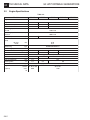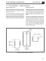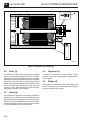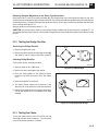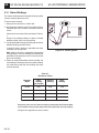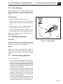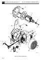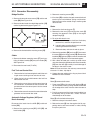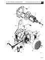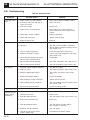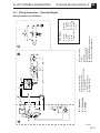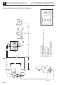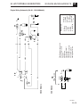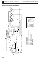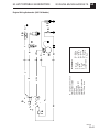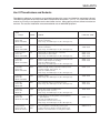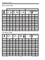
1
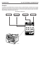
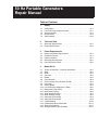
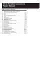
www.wackergroup.com
0116567
002
1000
en
Portable Generators
G 2.1A
G 3.3A
G 4.6A
GS 4.6A
GS 5.7A
REPAIR MANUAL
0
1
1
6
5
6
7
50 HZ PORTABLE GENERATORS
FOREWORD
This manual covers machines with Serial Number or Item Number:
0008243, 0008244, 0008245, 0008246, 0008247, 0008248, 0008249,
0008250, 0008251, 0008252, 0008253, 0008254, 0008255, 0008256, 0008257, 0008258, 0008259,
0008260, 0008261, 0008262, 0008263, 0008264, 0008265, 0008266, 0008267, 0008268, 0008269,
0008270, 0008271, 0008272, 0008273, 0008274, 0008275, 0008276, 0008277, 0008278, 0008279,
0008280, 0008281, 0008282, 0008283, 0008284, 0008285, 0008309, 0008310, 0008311, 0008312,
0008313, 0008314, 0008315, 0008316
Operating/Parts Information
You must be familiar with the operation of this machine before you attempt to troubleshoot or make any repairs to it.
Basic operating and maintenance procedures are described in the operator's/parts manual supplied with the machine.
The operator's/parts manual should be kept with the machine. Use it to order replacement parts when needed. If this
manual becomes lost, please contact WACKER Corporation to order a replacement.
Damage caused by misuse or neglect of the unit should be brought to the attention of the operator, to prevent similar
occurrences from happening in the future.
This manual provides information and procedures to safely repair and maintain this WACKER model. For your
own safety and protection from injury, carefully read, understand and observe the safety instructions described
in this manual. THE INFORMATION CONTAINED IN THIS MANUAL WAS BASED ON MACHINES IN PRODUCTION
AT THE TIME OF PUBLICATION. WACKER CORPORATION RESERVES THE RIGHT TO CHANGE ANY PORTION
OF THIS INFORMATION WITHOUT NOTICE.
FOREWORD
50 HZ PORTABLE GENERATORS
Nameplate
A nameplate listing the Model Number, Item Number, Revision, and Serial Number is attached to each unit. Please
record the information found on this plate so it will be available should the nameplate become lost or damaged. When
ordering parts or requesting service information, you will always be asked to specify the model, item number,
revision number, and serial number of the unit.
My machine’s numbers are:
Item Number
Serial Number
Revision
MENOMONEE FALLS, WI USA 53051
Model
GS4.6A
Item No.
Rev.
0008269
Serial No.
kg
hz
lbs
kW
class
V
5010101
101
N/M
A
GENERATING SET ISO 8528
MADE
IN USA
1031SD44
Insul.
Class
Man.
Yr.
110635
Model number
50 Hz Portable Generators
Repair Manual
Table of Contents
1
Safety
1.1
1.2
1.3
1.4
1.5
Safety Notes . . . . . . . . . . . . . . . . . . . . . . . . . . . . . . . . . . . . . . .
Laws Pertaining to Spark Arresters . . . . . . . . . . . . . . . . . . . . . .
Operating Safety . . . . . . . . . . . . . . . . . . . . . . . . . . . . . . . . . . . .
Engine Safety . . . . . . . . . . . . . . . . . . . . . . . . . . . . . . . . . . . . . .
Service Safety . . . . . . . . . . . . . . . . . . . . . . . . . . . . . . . . . . . . . .
2
Technical Data
2.1
2.2
Generator Specifications . . . . . . . . . . . . . . . . . . . . . . . . . . . . . . 2A-1
Engine Specifications . . . . . . . . . . . . . . . . . . . . . . . . . . . . . . . . . 2A-2
3
Power Requirements
3.1
3.2
3.3
3.4
3.5
Determining Power Requirements . . . . . . . . . . . . . . . . . . . . . . .
Outdoor Installation . . . . . . . . . . . . . . . . . . . . . . . . . . . . . . . . . .
Indoor Installation . . . . . . . . . . . . . . . . . . . . . . . . . . . . . . . . . . . .
Grounding the Generator . . . . . . . . . . . . . . . . . . . . . . . . . . . . . .
Use of Extension Cords . . . . . . . . . . . . . . . . . . . . . . . . . . . . . . .
4
Model G2.1A
4.1
4.2
4.3
4.4
4.5
4.6
4.7
4.8
4.9
4.10
4.11
4.12
4.13
4.14
4.15
4.16
4.17
4.18
4.19
4.20
Theory of Operation – Capacitor Generators . . . . . . . . . . . . . . . 4A-1
Rotor . . . . . . . . . . . . . . . . . . . . . . . . . . . . . . . . . . . . . . . . . . . . . 4A-2
Stator . . . . . . . . . . . . . . . . . . . . . . . . . . . . . . . . . . . . . . . . . . . . . 4A-2
Capacitor . . . . . . . . . . . . . . . . . . . . . . . . . . . . . . . . . . . . . . . . . . 4A-2
Diodes . . . . . . . . . . . . . . . . . . . . . . . . . . . . . . . . . . . . . . . . . . . . 4A-2
Circuit Breaker . . . . . . . . . . . . . . . . . . . . . . . . . . . . . . . . . . . . . . 4A-3
Earth Leakage Circuit Breaker (ELCB) . . . . . . . . . . . . . . . . . . . 4A-3
Capacitors . . . . . . . . . . . . . . . . . . . . . . . . . . . . . . . . . . . . . . . . . 4A-4
Engine Speed . . . . . . . . . . . . . . . . . . . . . . . . . . . . . . . . . . . . . . 4A-4
Loss of Residual Magnetism in Rotor . . . . . . . . . . . . . . . . . . . . . 4A-5
Receptacle Panel Wiring . . . . . . . . . . . . . . . . . . . . . . . . . . . . . . 4A-6
Rotor Diode Testing . . . . . . . . . . . . . . . . . . . . . . . . . . . . . . . . . . 4A-6
Stator Winding Testing . . . . . . . . . . . . . . . . . . . . . . . . . . . . . . . . 4A-7
Rotor Winding Testing . . . . . . . . . . . . . . . . . . . . . . . . . . . . . . . . 4A-8
Generator Disassembly . . . . . . . . . . . . . . . . . . . . . . . . . . . . . . . 4A-9
Generator Disassembly . . . . . . . . . . . . . . . . . . . . . . . . . . . . . . . 4A-9
Troubleshooting . . . . . . . . . . . . . . . . . . . . . . . . . . . . . . . . . . . . 4A-10
Periodic Maintenance Schedule . . . . . . . . . . . . . . . . . . . . . . . . 4A-11
Storing/Transporting . . . . . . . . . . . . . . . . . . . . . . . . . . . . . . . . 4A-11
Wiring Schematic (G2.1A Model) . . . . . . . . . . . . . . . . . . . . . . . 4A-12
1A-1
1A-1
1A-2
1A-3
1A-3
3A-1
3A-1
3A-1
3A-2
3A-2
50 Hz Portable Generators
Repair Manual
Table of Contents, continued
5
Models G3.3A, G4.6A, GS4.6A, & GS5.7A
5.1
5.2
5.3
5.4
5.5
5.6
5.7
5.8
5.9
5.10
5.11
5.12
5.13
5.14
5.15
5.16
5.17
5.18
5.19
5.20
5.21
5.22
5.23
5.24
Theory of Operation – Brush Generators . . . . . . . . . . . . . . . . . . 5A-1
Rotor . . . . . . . . . . . . . . . . . . . . . . . . . . . . . . . . . . . . . . . . . . . . . 5A-2
Stator . . . . . . . . . . . . . . . . . . . . . . . . . . . . . . . . . . . . . . . . . . . . . 5A-2
Automatic Voltage Regulator (AVR) . . . . . . . . . . . . . . . . . . . . . . 5A-2
Choke . . . . . . . . . . . . . . . . . . . . . . . . . . . . . . . . . . . . . . . . . . . . 5A-3
Bridge Rectifier . . . . . . . . . . . . . . . . . . . . . . . . . . . . . . . . . . . . . 5A-3
Engine Auto Idle Module . . . . . . . . . . . . . . . . . . . . . . . . . . . . . . 5A-3
Choke Test . . . . . . . . . . . . . . . . . . . . . . . . . . . . . . . . . . . . . . . . 5A-3
Main Circuit Breaker . . . . . . . . . . . . . . . . . . . . . . . . . . . . . . . . . 5A-4
Earth Leakage Circuit Breaker (ELCB) . . . . . . . . . . . . . . . . . . . 5A-4
Engine Speed . . . . . . . . . . . . . . . . . . . . . . . . . . . . . . . . . . . . . . 5A-6
Auto Idle Switch . . . . . . . . . . . . . . . . . . . . . . . . . . . . . . . . . . . . 5A-7
Loss of Residual Magnetism in Rotor . . . . . . . . . . . . . . . . . . . . 5A-9
Diode Bridge . . . . . . . . . . . . . . . . . . . . . . . . . . . . . . . . . . . . . . . 5A-9
Stator Windings . . . . . . . . . . . . . . . . . . . . . . . . . . . . . . . . . . . . 5A-10
Rotor Windings . . . . . . . . . . . . . . . . . . . . . . . . . . . . . . . . . . . . 5A-11
Slip Rings and Brushes . . . . . . . . . . . . . . . . . . . . . . . . . . . . . . 5A-11
Automatic Voltage Regulator . . . . . . . . . . . . . . . . . . . . . . . . . . 5A-11
Generator Disassembly . . . . . . . . . . . . . . . . . . . . . . . . . . . . . . 5A-13
Generator Assembly . . . . . . . . . . . . . . . . . . . . . . . . . . . . . . . . 5A-14
Troubleshooting . . . . . . . . . . . . . . . . . . . . . . . . . . . . . . . . . . . 5A-15
Periodic Maintenance Schedule . . . . . . . . . . . . . . . . . . . . . . . 5A-16
Wiring Schematics – Generator/Engine . . . . . . . . . . . . . . . . . 5A-17
Storing/Transporting . . . . . . . . . . . . . . . . . . . . . . . . . . . . . . . . 5A-22
50 HZ PORTABLE GENERATORS
1.1
SAFETY
1A
Safety Information
This manual contains DANGER, WARNING, CAUTION, and NOTE callouts which must be followed to reduce the
possibility of personal injury, damage to the equipment, or improper service.
!
This is the safety alert symbol. It is used to alert you to potential
personal injury hazards. Obey all safety messages that follow
this symbol to avoid possible injury or death.
! DANGER
DANGER indicates an imminently hazardous
situation which, if not avoided, will result in
death or serious injury.
! WARNING
WARNING indicates a potentially hazardous
situation which, if not avoided, could result in
death or serious injury.
! CAUTION
CAUTION indicates a potentially hazardous
situation which, if not avoided, may result in
minor or moderate injury.
CAUTION: Used without the safety alert symbol,
CAUTION indicates a potentially hazardous situation
which, if not avoided, may result in property damage.
Note: Contains additional information
important to a procedure.
1.2
Laws Pertaining to Spark Arresters
Notice: Some local authorities require that in certain locations, spark arresters be used on internal combustion engines.
A spark arrester is a device designed to prevent the discharge of sparks or flames from the engine exhaust. It is often
required when operating equipment on forested land to reduce the risk of fires. Consult the engine distributor or local
authorities and make sure you comply with regulations regarding spark arresters.
1A-1
1A SAFETY
50 HZ PORTABLE GENERATORS
WARNING
BACKFEED FROM THE GENERATOR INTO THE PUBLIC POWER DISTRIBUTION SYSTEM CAN
CAUSE SERIOUS INJURY OR DEATH TO UTILITY WORKERS!
Improper connection of generator to a building’s electrical system can allow electrical current from the generator
to backfeed into utility lines. This could result in electrocution of utility workers, fire, or explosion. Connections to
a building’s electrical system must be made by a qualified electrician and comply with all applicable laws and
electrical codes.
1.3
Operating Safety
Familiarity and proper training are required for the safe operation of electrical equipment! Equipment operated
improperly or by untrained personnel can be dangerous! Read the operating instructions and familiarize yourself with
the location and proper use of all instruments and controls. Inexperienced operators should receive instruction from
someone familiar with the equipment before being allowed to operate the generator.
WARNING
NEVER operate generator when open containers of
fuel, paint, or other flammable liquids are nearby.
NEVER operate generator, or tools attached to the
generator, with wet hands.
NEVER use worn electrical cords. Severe electrical
shock and equipment damage may result.
NEVER run generator indoors or in an enclosed area
unless adequate ventilation, through such items as
exhaust fans or hoses, is provided. Exhaust gas from
the engine contains poisonous carbon monoxide
gas; exposure to carbon monoxide can cause loss of
consciousness and may lead to death.
NEVER run electrical cords under the generator, or
over vibrating or hot parts.
NEVER enclose or cover generator when in use or
when hot.
NEVER overload generator. The total amperage of
the tools and equipment attached to the generator
must not exceed the load rating of the generator.
NEVER allow untrained personnel to operate or
service the generator. Know how to operate and stop
generator before starting it.
NEVER operate generator in snow, rain, or standing
water.
ALWAYS keep generator at least three feet (one
meter) away from structures, buildings, and other
equipment during use.
ALWAYS keep generator out of reach of children
and pets.
ALWAYS keep the area immediately surrounding
the generator clean, neat and free of debris.
ALWAYS position and operate generator on a firm,
level surface.
ALWAYS remove all tools, cords, and other loose
items from generator before starting it.
ALWAYS make certain generator is well-grounded
and securely fastened to a good earthen ground.
ALWAYS transport generator in an upright position.
1A-2
50 HZ PORTABLE GENERATORS
1.4
SAFETY
1A
Engine Safety
Internal combustion engines present special hazards during operation and fueling! Read and follow warning
instructions in engine owner’s manual and safety guidelines below. Failure to follow the safety guidelines described
below could result in severe injury or death.
WARNING
DO NOT run engine indoors or in an enclosed area
unless adequate ventilation, through such items as
exhaust fans or hoses, is provided.
DO NOT touch or lean against hot exhaust pipes.
DO NOT operate with the fuel tank cap loose or
missing.
DO NOT fill or drain fuel tank near an open flame,
while smoking, or while engine is running.
DO NOT add fuel to a hot or running engine.
DO NOT fill fuel tank indoors or in an enclosed area
unless adequate ventilation, through such items as
exhaust fans, is provided.
DO NOT start engine if fuel has spilled or an odor of
fuel is present. Move generator away from the spill
and wipe generator dry before starting.
1.5
Service Safety
Poorly maintained equipment can become a safety hazard! In order for the equipment to operate safely and properly
over a long period of time, periodic maintenance and occasional repairs are necessary. If the generator is experiencing
problems or is being serviced, attach a “DO NOT START” sign to the control panel to notify other people of its condition.
WARNING
NEVER allow water to accumulate around the
base of the generator set. If water is present,
move the generator and allow it to dry before
servicing.
NEVER service generator if clothing or skin is
wet.
NEVER use gasoline or other low flash point
solvents to clean air filter elements.
NEVER allow untrained personnel to service
this equipment. Only trained electrical technicians
should be allowed to service the electrical
components of this equipment.
NEVER modify the equipment without express
written approval from WACKER Corporation.
ALWAYS turn engine off before servicing generator.
If engine has electric start, disconnect negative
terminal on battery.
ALWAYS keep generator clean and labels legible.
Replace all missing and hard-to-read labels. Labels
provide important operating instructions and warn of
dangers and hazards.
ALWAYS let engine cool before transporting or
servicing.
ALWAYS remain aware of moving parts and keep
hands, feet, and loose clothing away from moving
parts on generator and engine.
ALWAYS keep fuel lines in good condition and
properly connected. Leaking fuel and fumes are
extremely explosive.
ALWAYS replace all guards and safety devices
immediately after servicing.
1A-3
1A SAFETY
Notes:
1A-4
50 HZ PORTABLE GENERATORS
50 HZ PORTABLE GENERATORS
2.1
TECHNICAL DATA
2A
Generator Specifications
Table 2-1.
Model
Output
kVA
Type
G2.1A
G3.3A
2,1
3,3
Frequency
GS4.6A
Automatic Voltage Regulator
230V 1Ø
400V 3Ø
230V
1 phase
Hz
GS5.7A
4,1 1Ø
5,7 3Ø
4,6
Brushless
AC Voltages available
voltage & phase
G4.6A
50
Power Factor
1,0 1Ø
0,8 3Ø
1,0
AC Receptacles
Optional
Main Circuit Breaker
amp
10 (1 pole)
15 (1 pole)
20 (1 pole)
9 (3 pole)
Continuous Current
at 230V/400V
amp
9,1/N.A.
14,3/N.A.
20,0/N.A.
18,0/8,2
LxWxH
mm
685 x 445 x 435
Kg
44
71
80
N/A
N/A
N/A
Weight (dry)
Battery
685 x 585 x 530
83
83
50-N18L-A/12/20
2A-1
2A TECHNICAL DATA
2.2
50 HZ PORTABLE GENERATORS
Engine Specifications
Table 2-2.
Model
G2.1A
G3.3A
G4.6A
Engine Make
Engine Model
Power @ 3000 rpm
Displacement cubic
Operating Speed –
no load
Operating Speed –
full load
Auto Idle Speed
Valve Clearance
(cold)
exhaust
intake
Spark Plug
kW
cm
rpm
GX 160 K1VX
GX 240 K1
GX 340 K1
4,1
163
6,0
242
8,2
337
rpm
rpm
3000 ± 50
2200 ± 50
N/A
mm
0,20
0,15
BPR6ES/W20EPR-U
type
mm
(type / V)
Alternator
Fuel
Fuel Consumption
Fuel Tank Capacity
Running Time
Air Cleaner
Engine Lubrication
amp
N/A
Type
liter/hr
1,7
liter
3,7
hr.
2,2
type
oil grade SAE 10W30
service SG, SF, or SE
class
600
ml
2A-2
GS5.7A
3100 ± 50
Spark Plug Gap
Star ter
Capacity
GS4.6A
Honda
N/A
N/A
0,7 – 0,8
N/A
Electric / 12V
N/A
N/A
Regular unleaded (Min. 77 Octane)
2,4
3,2
19,5
8,2
6,0
Dry type with oil-wetted foam pre-cleaner
SAE 10W30
SG or SF
1100
1
50 HZ PORTABLE GENERATORS
POWER REQUIREMENTS
3.1 Determining Power
Requirements
3.2
These generators are designed to operate single-phase,
50 hertz appliances or tools running at 230 VAC for the
G2.1A, G3.3A, G4.6A, and GS4.6A models, and a single
phase voltage of 230 VAC and a three phase voltage of
400 VAC for the GS5.7A model. Check the nameplate or
label provided on tools and appliances to make sure their
power requirements match the power output of the
generator.
Some appliances and tools require a surge of current
when starting. This means that the amount of power
needed to initially start the equipment is larger than the
power required to keep it running. The generator must be
capable of supplying this “surge” current. Other types of
appliances require more power than is actually stated on
their nameplates.
The chart below is offered only as a general guideline to
help you in determining power requirements for different
types of equipment. Check with your nearest WACKER
Dealer, or contact the manufacturer or dealer of the tool
or appliance, with questions regarding power
requirements.
•
•
•
•
•
Incandescent lights and appliances such as irons
and hot plates use a resistive-type heating element
and require the same wattage to start and run as is
stated on their nameplates.
Fluorescent and mercury lamps require 1.2 – 2 times
their stated wattage to start.
Electrical motors and many types of electrical tools
often require a large starting current. The amount of
starting current depends on the type of motor and its
use.
Most electrical tools require 1.2 – 3 times their stated
wattage for running.
Loads such as submersible pumps and air compressors require a very large force to start. They need as
much as 3 – 5 times the wattage stated on their
nameplates in order to start.
3A
Outdoor Installation
Place the generator in an area where it will not be
exposed to rain or snow. Make sure it is positioned on
firm, level ground so it will not slide or shift. Position
engine exhaust away from areas where people may be
present.
If operating the generator inside a tunnel or deep trench,
make sure there is adequate ventilation. Precautions
similar to those required when operating indoors may be
necessary.
The surrounding area must be free of water and moisture.
All components must be protected from excessive
moisture.
3.3
Indoor Installation
If the generator must be operated indoors, adequate
ventilation or exhaust hoses must be provided. When
venting exhaust fumes, make sure the exhaust piping is
large enough to prevent excessive back pressure to the
engine. Back pressure reduces engine efficiency and
may cause the engine to overheat.
WARNING
Exhaust gas from the engine contains poisonous
carbon monoxide gas; exposure to carbon monoxide
can cause loss of consciousness and may lead to
death. Never run generator indoors or in an enclosed
area unless adequate ventilation, through such items
as exhaust fans or hoses, is provided.
When operated indoors, steps to prevent fire and explosion
such as, providing a good earthen ground, removing all
flammable materials near generator, and using only
electric cords in good condition, must be observed. See
Section 1.3 Operating Safety.
If the wattage is not given for a particular tool or appliance, it can be calculated by multiplying its voltage and
amperage requirements:
VOLTS x AMPS = WATTS
CAUTION: If a tool or appliance does not reach full
speed within a few seconds when switched on, turn it off
immediately to avoid damage.
CAUTION: When starting loads, DO NOT exceed two
(2) times the given Continuous Current rating for model
G2.1A, or one-and-one-half (1 1/2) times for all other
models, as damage to the generator may occur. See
Section 2.1 Generator Specifications.
3A-1
3A POWER REQUIREMENTS
3.4
50 HZ PORTABLE GENERATORS
Grounding the Generator
The generator should be grounded to a good ground
source in compliance with National Electric Code standards and local regulations.
Use #8 wire and secure one end to the ground terminal
(a) provided on the generator frame and the other end to
a suitable ground source. See Figure 3-1.
a
1001SD02
Figure 3-1. Grounding
3.5
Use of Extension Cords
When a long extension cord is used to connect an appliance or tool to the generator, a voltage loss occurs – the longer
the cord, the greater the voltage loss. This results in less voltage being supplied to the appliance or tool and increases
the amount of current draw or reduces performance. A heavier cord with a larger wire size will reduce the voltage loss.
Use Table 3-1 below as a guide for selecting proper cable size.
Use only extension cords rated for outdoor use and equipped with a third-wire ground.
Table 3-1.
Current
Amps
2.5
5
7.5
10
15
20
Load in Watts
120V
240V
300
600
600
1200
900
1800
1200
2400
1800
3600
2400
4800
Maximum Cable Length in Ft.
#10
#12
#14
#16
1000 ft. 600 ft.
375 ft.
250 ft.
500 ft.
300 ft.
200 ft.
125 ft.
350 ft.
200 ft.
125 ft.
100 ft.
250 ft.
150 ft.
100 ft.
150 ft.
100 ft.
65 ft.
125 ft.
75 ft.
50 ft.
CAUTION: Operating equipment at low voltage can cause overheating.
WARNING
Keep electrical cords in good condition. DO NOT use worn,
bare, or frayed cords which can cause electrical shock.
3A-2
50 HZ PORTABLE GENERATORS
4.1
G2.1A/G2.1AE
4A
Theory of Operation – Capacitor Generators
Basic Generator Theory
Brushless Generator
Wacker air-cooled generators work on the principle of
electromagnetic induction i.e., the cutting of magnetic
lines of force by a coil of wire to produce an electric
voltage in the coil of wire.
This model generator uses a brushless design to generate
and regulate power. It consists of a rotor, stator, diodes,
and an auxiliary winding. The brushless generator also
contains a capacitor that is connected to the auxiliary
winding. Its purpose is to regulate the voltage in the main
windings and prevent a voltage drop when a load is
applied.
The two main components of the generator, the rotor and
stator, are the key. The rotor acts as the magnet and the
stator acts as the coil of wire. As the rotor rotates, its
magnetic lines of force are cut by the coils of wire in the
stationary stator. The voltage induced in the windings of
the stator is tapped off and available at the receptacles.
This generator is designed to operate with single phase
loads at or near a power factor of 1.0. The principle of
operation is schematically represented in Figure 4-1, and
a cross-sectional view in Figure 4-2. The auxiliary
winding (a), in conjunction with the capacitor, provide
excitation by inducing current in the rotor windings (b)
which is rectified by the diodes (c) to produce direct
current. The main stator winding (d) is designed for
parallel connection to give a voltage output with no
voltage adjustment possible.
c
Diodes
(Rectifier)
a
Auxiliary Winding
Capacitor
b
d
Main Windings
Rotor Field
Windings
1023SD44
Figure 4-1. Principle of Operation Schematic
4A-1
4A G2.1A/G2.1AE
a
50 HZ PORTABLE GENERATORS
b
d
c
1022SD88
Figure 4-2. Brushless Type Generator
4.2
Rotor (a)
The inside of the rotor shaft is tapered and connected
directly to the taper on the engine crankshaft. This end is
supported by the engine crankshaft bearing. The opposite end of the rotor is supported by a bearing installed in
the generator housing. This end also contains the two
diodes mounted on the diode bracket assembly. There
are two individual coils wound on the rotor. When the
engine is running, these two windings create the magnetic field for the main stator windings.
4.3
Stator (b)
The stator houses both the main windings and auxiliary
winding. The main windings are connected directly to the
main circuit breaker to supply power to the output receptacles. The auxiliary winding induces the initial voltage in
the field windings of the rotor and regulates the voltage.
It is connected directly to the main capacitor.
4A-2
4.4
Capacitor (c)
A capacitor is connected in series with the auxiliary
winding. Its purpose is to regulate the voltage when a
load is applied.
4.5
Diodes (d)
Two diodes are located on the rotor. These diodes form
a half wave rectifier to convert the induced AC voltage in
the rotor windings to DC voltage.
50 HZ PORTABLE GENERATORS
4.6
G2.1A/G2.1AE
4A
Control Panel
The generator is protected by a 10 amp circuit breaker
(a) located on the control panel.
b
c
d
e
The circuit breaker protects the generator from severe
overloads or short circuits. If the circuit breaker opens,
turn the engine off immediately and determine the cause
before restarting. Check the appliances and tools attached to the generator for defects and make sure their
power requirements do not exceed the power rating of
the generator.
When the circuit breaker opens, the breaker button will
pop out. To reset circuit breaker, push button in.
a
Depending on model, the generator will have one of the
four styles of receptacles, the Danish IP44 type (b), the
Swiss IP X4 type (c), the France/Belgium IP44 type (d),
or the Schuko IP44 (CEE 7) type (e).
Note: Enlargements of receptacles show protective
covers removed for identification purposes only. Never
remove protective covers.
4.7
230V
230V
Control Panel
a
b
c
d
e
1031SD43
Main circuit breaker - 10 Amp.
Danish IP44 style receptacle.
Swiss IP X4 style receptacle.
France/Belgium IP44 style receptacle.
Schuko IP44 (CEE 7) style receptacle.
Earth-leakage Circuit Breaker
Generator model G2.1AE is equipped with an earthleakage circuit breaker. The circuit breaker is current
operated and shuts off the power to the receptacles when
a ground fault of 30 milli-Amps or greater occurs in the
generator or to a piece of equipment attached to the
generator. The circuit breaker is located on the opposite
side of the generator as the control panel.
f1
The circuit breaker should be tested for proper operation
every time the generator is used.
f2
To test the earth-leakage circuit breaker:
Start the generator. Place main circuit breaker in closed
position. Push in TEST button (g). The circuit breaker
lever will lower to the open position (f2). Power is now off
at both receptacles. If the lever does not lower, the circuit
breaker is not working. Do not use the generator until the
problem can be corrected. To restore power to the
receptacles, raise the circuit breaker lever to the closed
position (f1).
T
E
S
T
g
1020SD80
If the circuit breaker lever lowers to the open position
during operation, stop the generator and check it and
equipment for defects. Repair all defects before operating generator.
4A-3
4A G2.1A/G2.1AE
4.8
50 HZ PORTABLE GENERATORS
Capacitors
4.9
WARNING
ALWAYS handle or test capacitors with the engine
stopped. Extremely high voltage is present at the
capacitor terminals while the generator is in use.
Although the capacitors used in this generator are
designed to discharge when the engine is stopped,
it is still a good idea to discharge them manually
before handling. To discharge a capacitor, place a
conductor, such as a screwdriver with an insulated
handle, across the capacitor terminals. Be sure to
touch only the insulated handle. This will short out
across the terminals and discharge the capacitor.
Testing Capacitor
1. Discharge capacitor as described above, then
disconnect all wire leads from the terminals.
2. Check the capacitor charge and discharge readings
using an ohmmeter as described below or use a
capacitor checker. See Figure 4-4.
Set Ohmmeter on R x 10k scale.
Set meter leads on capacitor terminals. The meter
should deflect momentarily towards zero (fully
discharged) and then slowly climb up to infinity
(charging).
Reverse meter leads and repeat procedure. Results
should be the same.
Engine Speed
All generators require a fixed engine speed to maintain
the correct voltage output. Engine speed is controlled by
a governor which automatically adjusts to varying loads
on the engine to maintain a constant speed of 3000 –
3100 rpm.
Testing Engine Speed
Measure the engine speed using a tachometer with no
load applied to the generator. The engine must be
running at 3100 ± 50 rpm. Voltage output is directly
related to engine speed. A slow engine will reduce
voltage. Refer to the Operator’s Manual for engine speed
adjustment.
The generator is designed to produce no output if
engine rpm falls 10% or more below the required
speed (approximately 2700 rpm).
Setting Engine Speed
Setting the engine speed requires the adjustment to the
governor. See Figure 4-5.
To set the engine to the proper speed:
Turn the engine speed adjusting screw (a) in or out
to obtain a no-load speed of 3100 rpm.
CAUTION: Setting the engine speed too high or too low
may damage tools and other appliances attached to the
generator.
a
3. If meter does not deflect torward zero, or deflects to
zero and remains there, the capacitor is open or
shorted and must be replaced.
1001SD15
Figure 4-5. Engine Speed Adjusting Screw
1007SD87
Figure 4-4. Testing Capacitor
4A-4
50 HZ PORTABLE GENERATORS
G2.1A/G2.1AE
4A
4.10 Loss of Residual Magnetism in Rotor
If the rotor has been removed, or the generator has been
stored over six months, the rotor’s magnetism may be
lost. Loss of magnetism will prevent the generator from
building voltage.
To restore magnetism to the rotor, “flash” it as follows:
1. Remove the two screws and the end cover. Locate the
capacitor that is attached to the stator housing.
2. Run generator at normal no-load speed – 3100 rpm,
auto-idle off.
WARNING
Contact with exposed connections inside the control
box or while handling battery leads can cause severe electrical shocks. Be extremely careful to avoid
touching any exposed connections. Never wear
jewelry or use tools or metal items that may make
contact across exposed connections. Review safety
rules at beginning of this manual.
3. Briefly touch a 12 VDC battery across the two capacitor
connections to pulse the auxiliary winding. The leads
should remain attached to capacitor. The polarity of
the battery leads is not important.
CAUTION: DO NOT hold battery leads on connection
longer than two seconds.
The output voltage should quickly come up to normal
levels. Repeat if necessary. See Figure 4-6.
4. Stop engine and replace end cover.
Stator Housing
Capacitor
12 VDC
Battery
1023SD45
Figure 4-6. “Flashing” the Rotor
4A-5
4A G2.1A/G2.1AE
50 HZ PORTABLE GENERATORS
4.11 Receptacle Panel Wiring
4.12 Rotor Diode Testing
Remove receptacle panel from control box and inspect
the wiring for worn or loose wires. Make sure all wire
connections are secure and tight at the screws. DO NOT
allow wires to be pinched, kinked or damaged in any
way. Inspect for tight connections at circuit breakers,
capacitors, switches and receptacles. Replace any
broken or damaged parts.
To check diode:
1. Disassemble generator and remove rotor. See Section
4.15 Generator Disassembly.
2. Set ohmmeter in lowest scale. Test diode in forward
position. Meter should read low or close to zero.
3. Reverse meter leads and test diode in reverse position.
Meter should read high or close to infinity.
A zero reading in both directions indicates a shorted
diode. A reading of Infinity in both directions indicates an
open diode. The diode must be replaced in either case.
If one diode is defective it is recommended that both
diodes be replaced since the remaining diode may have
been weakened.
To remove diode, use a soldering iron to soften solder
and remove wires.
When soldering on wires do not allow soldering iron to
remain on diodes longer than 10 seconds or diode may
be damaged.
LOW VALUE
HIGH VALUE
POS
NEG
NEG
POS
1024SD03
Figure 4-7. Rotor Diode Testing
4A-6
50 HZ PORTABLE GENERATORS
G2.1A/G2.1AE
4A
4.13 Stator Winding Testing
The stator includes the main winding and the auxiliary
winding.
Auxiliary Windings
To check stator windings:
1. Unplug stator connector at control box.
Capacitor
2. Disconnect ground wire.
3. Set ohmmeter to lowest scale. Place meter leads on
connector terminals as shown and record resistance
values, see Figure 4-8.
Check resistance values with those listed on Table 4-1.
A high or low reading indicates an open or shorted
winding and the stator must be replaced.
4. Test for grounded windings by checking for continuity
between winding and metal frame.
If continuity exists, winding is grounded and stator
assembly must be replaced.
Note: Make sure stator is completely disconnected
from generator. The main winding is intentionally
grounded to the generator to form a neutral and will
give a false reading.
1023SD46
Figure 4-8. Stator Winding Testing
5. Check for continuity between auxiliary winding and
main winding. If continuity exists, the auxiliary winding
has a short to the main winding and stator must be
replaced.
6. Test the auxilliary windings by disconnecting themfrom
the capacitor and taking a resistance reading. Reading
should compare with the value in Table 4-1.
Table 4-1.
Resistance Values (Ohms)
Main
Winding
Auxiliary
Winding
Rotor
Winding
0,918
1,04
8,12
Resistance values are very small and require a good
quality meter with the ability to be zeroed out. A poor
quality meter may not provide accurate readings.
All resistance values are approximate.
4A-7
4A G2.1A/G2.1AE
50 HZ PORTABLE GENERATORS
4.14 Rotor Winding Testing
Before testing rotor, visually inspect windings for dark
streaks which indicate a burned or shorted winding.
Rotate ball bearing by hand. Replace it if it is rough or
noisy.
To check rotor:
1. Remove end cover, locknut, stator and rotor from
generator. See Section 4.15 Generator Disassembly.
2. Unsolder wires from diodes, being careful not to break
wires.
NEG
3. Measure rotor resistance as shown in Figure 4-9.
4. Record resistance values of both windings and compare them with values listed in Table 4-1.
5. Check for grounded windings by holding one meter
lead to winding and other lead to metal frame on rotor.
POS
1024SD04
Figure 4-9. Rotor Winding Testing
Replace rotor if windings are open, shorted internally or
shorted to metal frame.
3
4
5
2
8
7
13 ft. lbs.
(17.5 Nm)
5
1
9
15
10
14
13
12
11
1023SD47
Figure 4-10. Brushless Generator
4A-8
50 HZ PORTABLE GENERATORS
G2.1A/G2.1AE
4A
4.15 Generator Disassembly
Capacitor
Diode and/or Varistor
1. Remove the two end cover screws (10) and the end
cover (9). See Figure 4-10.
1. Unsolder leads from the diodes (5) and (8) and
unscrew diode stud. See Figure 4-10.
2. Disconnect the leads from the capacitor (11), cut the
nylon tie wrap, and remove the capacitor mounting
screw.
2. Unsolder varistor lead from the solder tag on the
diode stud.
Stator
3. Remove the silicon sealant supporting the varistor
from the diode bracket (4).
1. Remove the control panel, unscrew the ground wire
(14) and unplug the stator wire (15) from the back of
the panel. See Figure 4-10.
2. Remove the shaft securing nut (7).
3. Remove the four nuts (13) securing the generator
frame (12) to the engine adapter flange.
4. Remove the two bolts and nuts that secure the stator
(12) to the shock mount bracket.
5. With a block of wood and a mallet, tap stator frame
away from the engine. Withdraw stator frame
assembly (12) over the rotor (3) carefully to avoid
damage to windings in the stator or rotor.
4.16 Generator Assembly
When assembling the generator be sure to observe the
following:
1. Install diodes (5) to the diode bracket (4) assembly
on the rotor, by placing the solder tags on the diode
stud and tighten to the diode base. See Figure 4-10.
Note: If the rotor comes out with the stator,
skip step 6.
2. Insert varistor leads first, and push varistor well
down into the diode bracket assembly recess. Solder
leads to the diode pin and the solder tag on the diode
stud. Reseal varistor with silicon sealant.
6. Support the rotor weight with a sling or place a block
between the rotor and base.
3. Make sure inner taper on rotor and outer taper on the
engine crankshaft are clean and free of rust and oil.
Rotor
4. Install the rotor (3) on crankshaft.
Rotor (3) removed with stator:
5. Slide stator (12) over the rotor carefully to avoid
hitting and damaging windings. Tap the frame onto
the rotor bearing.
1. Place stator on flat surface with bearing (8) end up.
Elevate the stator (12) by placing two blocks of wood
on the edge of the stator frame to allow the rotor to
drop. See Figure 4-10.
2. Partially screw one of the frame mounting bolts into
the bearing and tap screw with a mallet. The rotor
should drop out of the stator.
Rotor (3) still attached to the engine:
1. Remove stator per instructions above.
2. Release the rotor (3) from the engine shaft by
supporting rotor in one hand and with a mallet,
striking firmly on a pole face.
6. Attach the four nuts (13) to secure frame to the
engine adapter flange.
7. Install the shaft securing nut (7). Tighten to 13 ft. lbs.
(17.5 Nm).
8. Install the capacitor (11) using the mounting screw
and a new nylon tie wrap. Re-attach the two leads.
9. Install the end cover (9) and two mounting screws
(10).
10. Reconnect the ground wire (14) and the stator wire
(15) to the control panel, and reinstall panel.
4A-9
4A G2.1A/G2.1AE
50 HZ PORTABLE GENERATORS
4.17 Troubleshooting
Table 4-2.
Generator Chart
Symptom
Engine Does Not
Start
Possible Cause
1. Engine switch is in “OFF” position.
1. Move engine switch to “START” position.
2. Fuel valves under fuel tank and on
engine are closed.
2. Open fuel valves.
3. Fuel tank is empty.
3. Fill fuel tank.
4. Choke lever is in wrong position.
4. Move choke lever to correct position.
(Close choke lever when starting
a cold engine).
5. Spark plug is in poor condition.
5. Replace spark plug.
6. Spark plug cap is loose.
6. Tighten spark plug cap.
7. Engine oil level is low.
7. Refill oil.
No Output Voltage 1. Engine speed too slow.
Low Voltage
Solution
1. Increase engine speed to 3100 rpm,
no-load. (See section 4.9)
2. Circuit breaker open.
2. Reset breaker.
3. GFI open.
3. Test and reset ELCB. Replace if defective.
Tool or appliance defective, leaking current.
(See section 4.7)
4. Loss of residual magnetism.
4. Flash rotor fields. (See section 4.10)
5. Defective receptacle or switch.
5. Inspect wiring and components and repair.
(See section 4.11)
6. Rotor diodes open or shorted.
6. Test diodes and replace. (See section 4.12)
7. Open or shorted stator windings.
7. Test stator and replace. (See section 4.13)
8. Open or shorted rotor windings.
8. Test rotor and replace. (See section 4.14)
9. Connector from generator to control
panel is loose or disconnected.
9. Install tightly.
1. No-load voltage between 140 – 200
volts, engine operating at correct
speed.
2. Engine slightly below operating speed,
but not enough to collapse all output.
1.
3. Capacitor is defective.
3. Test capacitor and replace if necessary.
(See section 4.8)
4. Rotor winding wire broken off at diode.
4. Resolder wire to diode.
5. Rotor winding partially shorted.
5. Test rotor winding resistance. Replace
rotor.
(See section 4.14)
6. Rotor winding partially shorted.
6. Rotor slipping on engine crankshaft.
One diode on rotor open or shorted.
Replace all diodes. (See section 4.12)
2. Increase engine speed to 3100 rpm,
no-load. (See section 4.9)
High Voltage
1. Engine speed too high.
1. Reduce engine speed to 3100 rpm,
no-load. (See section 4.9)
No-load Voltage
Normal but Falls
when Load is
Applied
1. Engine lugging down under load.
1. Refer to engine repair manual to restore
engine power.
4A-10
50 HZ PORTABLE GENERATORS
G2.1A/G2.1AE
4A
4.18 Periodic Maintenance Schedule
Daily
Before
Starting
Check engine oil. Fill to correct level.
•
Check air cleaner.
•
Clean air cleaner.*
Every 3
months or
50 hours
Every 6
months or
100 hours
Every
year or
300 hours
Every
year or
500 hours
•
Change engine oil.
•
Check sediment cup at carburetor.
•
Clean and adjust spark plug.
•
Clean spark arrester (optional accessory).
•
Check shockmounts. Replace when necessary.
•
Check and adjust valve clearance.*
•
Clean fuel tank.*
•
Check condition of fuel line.
Replace when necessary.
•
•
* Service more frequently in dusty conditions.
Table 4-3.
Engine Service
Normal servicing of the engine such as cleaning the air cleaner, sediment cup, carburetor adjustments, auto idle speed
and engine speed can be located in the Operator’s manual. In depth engine service should be performed by qualified
personnel or by the nearest Honda dealer.
4.19 Storing/Transporting
1. Close the fuel valve and remove and empty sediment
cup under carburetor.
5. Remove the spark plug and pour approximately one
tablespoon (1 ounce) of clean engine oil into the
cylinder. Crank the engine a few turns to distribute the
oil to the inside of the cylinder walls.
2. Disconnect the fuel line from the carburetor. Place
open end of fuel line into a suitable container and open
fuel valve to drain fuel from tank.
6. Pull the starter rope slowly until resistance is felt and
leave handle in this position. This ensures that the
intake and exhaust valves are closed.
Before storing generator for a long period of time:
WARNING
Gasoline is extremely flammable. Drain fuel tank in
a well-ventilated area. DO NOT drain tank in an area
with flames or sparks.
3. Loosen the drain screw on the carburetor and drain
any remaining fuel from carburetor.
4. Change the engine oil.
7. Store generator in a clean, dry area.
WARNING
To avoid burns or fire hazards, let engine cool before
transporting generator or storing indoors.
Turn the fuel valves under the tank and on engine to
the off position and keep the engine level to prevent
fuel from spilling.
4A-11
4A-12
1
1
8
9
L
Br
W
R
1
2
B = Control box
C = Engine
LL
G/Y
3 Br
4
R
G/Y
LL
2
G/Y
1
2
B(2)
B(4)
B(1) B(3)
R/B
3
G/Y
LL/B
G/Y
LL/Gr
B/R
C
R/Gr
7
B
1 = Main stator winding
2 = Main circuit breaker
3 = Earth-leakage circuit breaker (G2.1AE only)
4 = Ignition switch
5 = Oil level switch
6 = Coil
7 = 16 Amp receptacle
8 = Rotor winding
9 = Capacitor (25µF)
10 = Auxiliary winding
R/W
2
1
A = Generator
B
10 B
A
7
B - Black
G - Green
L - Blue
P - Pink
R - Red
LL-Light blue
Wire Colors
B
Y
B
4
G
W- White
Y - Yellow
Br - Brown
Gr - Gray
Or - Orange
Pr - Purple
T - Tan
6
5
4A G2.1A/G2.1AE
50 HZ PORTABLE GENERATORS
4.20 Wiring Schematic (G2.5A Model)
1020SD79
50 HZ PORTABLE GENERATORS
5.1
G3.3A/G4.6A/GS4.6A/GS5.7A 5A
Theory of Operation – Brush Generators
Basic Generator Theory
These generator models use a brush/slip ring design to
generate and regulate power and consist of a rotor,
stator, diode bridge, and an auxiliary winding. They also
incorporate a choke that is connected in series with the
auxiliary winding. The choke’s purpose is to bring the
current in the auxiliary winding “in phase” with the main
windings. The current from the auxiliary winding is carried
to the rotor via the brushes and slip rings.
The generators also contain an Automatic Voltage
Regulator (AVR) that maintains a specific voltage output
regardless of load. The voltage regulator accomplishes
this by regulating DC current from the auxiliary winding.
When the load on the generator increases, the voltage
regulator allows additional DC current into the main rotor.
The additional DC current allows the generator to increase
output and maintain the desired output voltage.
These models are designed to operate with close
regulation when supplying single phase loads. The
principle of operation is schematically represented in
Figure 5-1, and a cross-sectional view in Figure 5-2. The
auxiliary winding (a) provides excitation power through
a choke (b) and bridge rectifier (c) into the rotor winding
(d) via slip rings and brushes. The AVR (e) diverts
excess excitation to maintain the stator winding (f)
output voltage within close limits. The main stator winding
is designed for series/parallel connection to give a dual
voltage output.
Automatic
Voltage
Regulator
e
Brush and Slip
Ring Assembly
Bridge Rectifier
c
Auxiliary
Winding
a
d
Rotor
Winding
f
b
Choke
Main
Stator
Winding
f
Main
Stator
Winding
1022SD73
Figure 5-1. Principle of Operation Schematic
5A-1
5A G3.3A/G4.6A/GS4.6A/GS5.7A
50 HZ PORTABLE GENERATORS
F1
a
e
Z3
b
F2
Z2
d
F1
F2
F2
c
F1
L2
L1
Voltage Adjust Pot
1023SD48
Figure 5-2. Brush-Type Generator
5.2
Rotor
The inside of the rotor shaft is tapered and connected
directly to the taper on the engine crankshaft. This end is
supported by the engine crankshaft bearing. The opposite end of the rotor is supported by a bearing housed in
the generator housing. This end also contains the two slip
rings. There are two individual coils wound on the rotor
(a). When the engine is running, these two windings
create the magnetic field for the main stator windings.
5A-2
5.3
Stator
The stator (b) houses both the main windings and
auxiliary winding. The main windings are connected
directly to the main circuit breaker and voltage selector
switch to supply power to the output receptacles. The
auxiliary winding induces the initial current in the field
windings of the rotor. It is connected directly to the choke
and the AC input to the bridge rectifier.
50 HZ PORTABLE GENERATORS
5.4
G3.3A/G4.6A/GS4.6A/GS5.7A 5A
Automatic Voltage Regulator (AVR)
The Automatic Voltage Regulator (AVR) (c) provides the
generator with a means of maintaining a specific voltage
regardless of load. The AVR accomplishes this by
regulating DC current from the auxiliary winding. When
the load on the generator increases, the AVR allows
additional DC current into the rotor. The additional DC
voltage allows the generator to increase output and
maintain voltage.
5.5
Choke
The purpose of the choke (d) is to bring the auxiliary
winding “in phase” with the main windings.
5.6
Bridge Rectifier
The bridge rectifier (e) is located on the stator housing
and is placed in a cooling air flow of the rotor. This bridge
rectifier forms a full wave rectifier to convert induced AC
current in the auxilliary winding to DC current.
5A-3
5A G3.3A/G4.6A/GS4.6A/GS5.7A
5.7
Main Circuit Breaker
50 HZ PORTABLE GENERATORS
5.8
The circuit breaker protects the generator from severe
overloads or short circuits. If the circuit breaker opens,
turn the engine off immediately and determine the cause
before restarting. Check the appliances and tools attached
to the generator for defects and make sure their power
requirements do not exceed the power rating of the
generator or the current limit of the receptacles.
When the circuit breaker opens, the breaker lever will
snap down. To reset the circuit breaker, lift lever up. See
Figures 5-5 and 5-6.
Earth-leakage Circuit Breaker
Generator models G3.3AE, G4.6AE, GS4.6AE, and
GS5.7AE are equipped with an earth-leakage circuit
breaker. The circuit breaker is current-operated and
shuts off the power to the receptacles when a ground fault
of 30 milli-Amps or greater occurs in the generator or to
a piece of equipment attached to the generator. The
circuit breaker is located on the control panel and should
be tested for proper operation every time the generator
is used.
To test the earth-leakage circuit breaker:
Start the generator. Place main circuit breaker in closed
position. Push the TEST button (g) on the circuit breaker.
The circuit breaker lever will lower to the open position
(a2). Power is now off at both receptacles. If the lever
does not lower, the circuit breaker is not working. Do not
use the generator until the problem can be corrected. To
restore power to the receptacles, raise the circuit breaker
lever to the closed position (a1).
If the circuit breaker lever lowers to the open position
during operation, stop the generator and check it and
equipment for defects. Repair all defects before operating generator.
a1
a1
a2
a2
T
E
S
T
g
1020SD80
Figure 5-4a. ELCB for G3.3AE, G4.6AE, and
GS4.6AE Models
5A-4
g
1020SD89
Figure 5-4b. ELCB for GS5.7AE Models
G3.3A/G4.6A/GS4.6A/GS5.7A 5A
50 HZ PORTABLE GENERATORS
b
c
d
e
f
a
a1
2
1
5
3
6
1
4
3
2
a2
230V
Control Panel
a
b
c
d
e
f
g
Main circuit breaker - 15 Amp.
Australian style receptacle.
Danish IP44 style receptacle.
Swiss IP X4 style receptacle.
France/Belgium IP44 style receptacle.
Schuko IP44 (CEE 7) style receptacle.
Earth-leakage circuit breaker (G3.3AE, G4.6AE, GS4.6AE).
T
E
S
T
g
230V
1031SD41
Figure 5-5. Control Panel (G3.3A, G4.6A, and GS4.6A Models)
c
b
d
e
f
a
j1
j2
j3
a1
1
2
5
3
4
6
1
3
2
230V
a2
j
Control Panel
a
b
c
d
e
f
g
h
j
Main circuit breaker - 9 Amp.
Australian style receptacle.
Danish IP44 style receptacle.
Swiss IP X4 style receptacle.
France/Belgium IP44 style, 230 Volt receptacle.
Schuko IP44 (CEE 7) style, 230 Volt receptacle.
Earth-leakage circuit breaker (GS5.7AE).
3 Phase/400 volt (CEE 17, 3P+N+E, IP44)receptacle.
Engine crank switch.
h
400V
g
1031SD42
Figure 5-6. Control Panel (GS5.7A Models)
5A-5
5A G3.3A/G4.6A/GS4.6A/GS5.7A
5.9
50 HZ PORTABLE GENERATORS
Engine Speed (G3.3A, G5.7A, and GS5.7A Models)
Generators require a fixed engine speed to maintain the
correct voltage. Engine speed is controlled by a governor
which automatically adjusts to varying loads on the
engine to maintain a constant speed of 3600 rpm. There
is no throttle control.
k
To set the engine to the proper speed:
Turn the speed adjusting screw (k) in or out to obtain a
no-load speed of 3100 rpm. See Figure 5-7.
CAUTION: Setting the engine speed too high or too low
may damage tools and other appliances attached to the
generator.
1001SD15
Figure 5-7. Engine Speed Adjusting Screw
5A-6
G3.3A/G4.6A/GS4.6A/GS5.7A 5A
50 HZ PORTABLE GENERATORS
5.10 Periodic Maintenance Schedule (G3.7A, G5.6A, and GS5.6A Models)
Daily
Before
Starting
Check engine oil. Fill to correct level.
•
Check air cleaner.
•
Clean air cleaner.*
Every 3
months or
50 hours
Every 6
months or
100 hours
Every
year or
300 hours
•
Change engine oil.
•
Check sediment cup at carburetor.
•
Clean and adjust spark plug.
•
Clean spark arrester (optional accessory).
•
Check shockmounts. Replace when necessary.
•
Check and adjust valve clearance.*
•
Clean fuel tank.*
•
Check condition of fuel line.
Replace when necessary.
•
Check condition of brushes** and slip rings
for G3.7A, G5.6A and GS5.6A Models
* Service more frequently in dusty conditions.
** Brushes should not be less than 8mm long.
Every
year or
500 hours
•
Table 5-3
Engine Service (G3.7A, G5.6A, and GS5.6A Models)
Normal servicing of the engine such as cleaning the air cleaner, sediment cup, carburetor adjustments, auto idle speed
and engine speed can be located in the Operator’s manual. In depth engine service should be performed by qualified
personnel or by the nearest Honda dealer.
5A-7
5A G3.3A/G4.6A/GS4.6A/GS5.7A
50 HZ PORTABLE GENERATORS
Z1
Z3
c
F2
b
F1
a
1031SD62
Figure 5-11. Brush Type Generator
5.11 Loss of Residual Magnetism in Rotor
General
If the rotor has been removed, the generator stored for a considerable time, or the rotor (field) connections reversed
during service, the residual magnetism may have been destroyed. Loss of magnetism will prevent the generator from
building voltage.
To check residual voltage, run the generator at normal no-load speed and measure the voltage at 120 VAC
receptacles. This voltage should be at least 1.5 volts. If the voltage is less than 1.5 volts, the residual magnetism must
be restored by “flashing” with a 12 volt battery.
5A-8
50 HZ PORTABLE GENERATORS
G3.3A/G4.6A/GS4.6A/GS5.7A 5A
Restoring Residual Magnetism to the Brush Type Generators
Disconnect leads F1 and F2 from the brush holder (a). Run the generator at its normal speed and apply 12 volts from
a battery to the brush holder for approximately 3 seconds. Ensure the positive lead is applied to the brush holder nearest
the bearing housing. The output voltage of the generator, with the 12 volt supply connected, should be approximately
normal voltage. See Figure 5-12.
Stop the generator and reconnect leads F1 – F2.
CAUTION: Ensure the battery leads are connected to the brush holder with the correct polarity, and leads F1 – F2
are isolated from each other and earth. Loss of residual magnetism will result if leads touch ground, each other, or wrong
polarity.
5.12 Testing the Bridge Rectifier
Accessing the Bridge Rectifier
F1
1. Remove the generator cover.
2. Remove leads Z2 and Z3 from the bridge rectifier (b),
and leads F1 and F2 that go to the brush assembly.
Z3
F2
Checking Bridge Rectifier
To check the rectifier, follow these steps:
F1
Z2
Z3
F2
Z2
1023SD52
1. Set multi-meter on R x 1000 range.
Figure 5-12. Diode Bridge
2. Remove all wires connected to the rectifier.
3. Place the meter probes on two adjacent rectifier
terminals and check resistance value. See Figure
5-13.
4. Reverse the probes and recheck.
5. The meter should indicate low resistance in one
direction and a high resistance in the other direction.
6. Repeat this procedure for each adjacent set of terminals on the rectifier until all four diodes have been
checked.
1023SD98
Figure 5-13. Checking Diode Bridge
5.13 Testing the Choke
To test the choke remove wires Z1 and Z3 from the
choke (c) and the choke assembly. The resistance
value of the choke should be 7.5 ohms.
5A-9
5A G3.3A/G4.6A/GS4.6A/GS5.7A
50 HZ PORTABLE GENERATORS
5.14 Stator Windings
The stator includes the two main power windings and the
auxiliary winding. See Figure 5-14.
To check stator windings:
1. Unplug stator connector at control box.
2. Set ohmmeter to lowest scale. Place meter leads on
connector terminals as shown and record resistance
values.
Check resistance values with those listed on Table 51.
A high or low reading indicates an open or shorted
winding and the stator must be replaced.
3. Test for grounded windings by checking for continuity
between winding and metal frame.
1024SD05
If continuity exists, winding is grounded and stator
assembly must be replaced.
Note: Make sure stator is completely disconnected
from generator. The main windings are intentionally
grounded to the generator to form a neutral and will
give a false reading.
Figure 5-14. Checking Stator
4. Check for continuity between auxiliary winding and
main windings. If continuity exists, the auxiliary winding
has made contact with the main winding and stator
must be replaced.
Table 5-1.
Resistance Values
Generator
Model
Main
Winding
(per section)
Auxiliary
Winding
Rotor
Winding
G3.3A
0.45
2.09
10.8
G4.6A
0.39
1.97
11.3
GS4.6A
0.39
1.97
11.3
GS5.7V
1.72
—
11.3
Resistance values are very small and require a good quality meter with the ability
to be zeroed out. Using a poor quality meter may not provide accurate readings.
All figures are approximate values in ohms.
5A-10
50 HZ PORTABLE GENERATORS
G3.3A/G4.6A/GS4.6A/GS5.7A 5A
5.15 Rotor Windings
Before testing rotor, visually inspect windings for dark
streaks which indicate a burned or shorted winding.
Rotate ball bearing by hand. Replace it if it is rough, noisy
or dry.
Checking Rotor
1. Remove end cover and brush assembly.
2. Measure resistance as shown in the illustration, by
measuring the winding at the slip rings. See Figure
5-15.
3. Record resistance values of both windings and
compare them with values listed in Table 5-1.
4. Check for grounded windings by holding one meter
lead to winding and other lead to metal frame on rotor.
Replace rotor if windings are open, shorted internally or
shorted to metal frame.
5.16 Slip Rings and Brushes
1024SD02
Slip Rings
Figure 5-15. Checking Rotor
Inspect the slip rings for dirt or damage. If the slip rings
are dirty, use an eraser or non-metallic abrasive pad to
clean the rings and then retry the generator.
Brushes
Inspect the brushes for damage, dirt, freedom of
movement, or brush length. Brushes less than 8 mm in
length should be replaced. Also replace damaged
brushes.
5.17 Automatic Voltage Regulator
To check the regulator:
•
If the generator has low voltage, approximately 2 – 5
VAC as measured at the 120 VAC receptacles,
remove F1 and F2 from the regulator. Start and run
the generator. If voltage output is approximately 150
VAC measured at the receptacles and engine speed
is 3750 rpm, replace regulator.
•
If the generator has low voltage, approximately 65
VAC measured at the 120 VAC receptacles, remove
F1 and F2 from the regulator. Start and run the
generator. If voltage output is approximately 150
VAC measured at the receptacles, and engine speed
is 3750 rpm, replace regulator.
•
If the generator has high voltage, approximately 150
VAC as measured at the 120 VAC receptacles, and
the engine speed is 3750 rpm, replace regulator.
5A-11
5A G3.3A/G4.6A/GS4.6A/GS5.7A
50 HZ PORTABLE GENERATORS
2
4
1
8
10
7
11
16
15
14
17
30
18
31
21
22
19
23
20
25
24
Figure 5-16. Brush Type Generator
5A-12
1020SD78
50 HZ PORTABLE GENERATORS
G3.3A/G4.6A/GS4.6A/GS5.7A 5A
5.18 Generator Disassembly
Bridge Rectifier
2. Remove 3 mounting screws (25).
1. Remove the two end cover screws (19) and the end
cover (20). See Figure 5-16.
3. If brushes (22) are to be changed, remove the brush
terminal plate and withdraw springs and brushes.
New brushes must be seated using a medium grade
abrasive cloth.
2. Remove the four leads from the bridge rectifier (16)
confirming lead markings per Figure 5-17.
1. Remove the shaft securing nut (7).
F1
Z3
F1
Z2
Z3
Stator
2. Remove the four nuts (11) from the four studs (2)
securing the generator frame (14) to the engine
adapter flange (1).
3. For units with electric start:
F2
F2
Z2
1023SD53
Figure 5-17. Diode Bridge Rectifier
3. Remove the choke/rectifier mounting screw (15).
Choke
1. Remove the bottom mounting screw (17) and carefully pull choke assembly (18) away from stator (14).
See Figure 5-16.
2. Disconnect the two leads (Z1 & Z3).
A. Disconnect the negative lead from the battery
terminal first, and then the positive lead.
B. Loosen battery mounting bracket nuts and slide
mounting bracket off the battery.
C. Remove battery and store in cool dry place.
4. Remove the two bolts (30) and nuts (31) that mount
the stator (14) to the lifting bracket (10). Remove the
two bolts (30) and nuts (31) that mount the other end
of the stator (14) to the shock mounted support.
5. With a block of wood and a mallet, tap stator frame
away from the engine. Withdraw stator frame assembly
(14) over the rotor (4) carefully to avoid damage to
windings in the stator or rotor.
Fuel Tank and Control Box
Note: On some occasions, the rotor may come out with
the stator. If it does, skip step 6.
1. Remove the fuel tank mounting bolts and tilt the tank
to gain access to the gas line and shut off valve.
6. Support the rotor weight with a sling or place a block
between the rotor and base.
2. Close the fuel valve and disconnect the fuel line.
Remove the fuel tank.
Rotor
3. Remove the screws that mount the control panel to
the control box, and disconnect the harnesses and
ground wire from the control panel. Set the control
panel aside.
Rotor (3) removed with stator:
1. Place stator (14) on flat surface with bearing (8) end
up. Elevate the stator by placing two blocks of wood
on the edge of the stator frame to allow the rotor to
drop.
4. Remove the screws that mount the control box to the
generator and set control box aside.
2. Partially screw one of the frame mounting bolts into
the bearing and tap screw with a mallet. The rotor
should drop out of the stator.
Automatic Voltage Regulator (AVR) and
Brush Assembly
Rotor (3) still attached to the engine:
Disconnect the leads from the AVR (24) and brush
holder (23).
2. Release the rotor (3) from the engine shaft by supporting rotor in one hand and with a mallet, striking
firmly on a pole face.
1. Remove the mounting screw (21), AVR (24) and
brush holder (23).
1. Remove stator per instructions above.
5A-13
5A G3.3A/G4.6A/GS4.6A/GS5.7A
50 HZ PORTABLE GENERATORS
5.19 Generator Assembly
When assembling the generator be sure to observe the
following:
6. If brushes were changed, reinstall the brushes,
springs and terminal plate.
1. Make sure inner taper on rotor and outer taper on the
engine crankshaft are clean and free of rust and oil.
See Figure 5-16.
Note: New brushes must be seated using a medium
grade abrasive cloth.
2. Install the rotor (4) on crankshaft.
7. Attach AVR (24) to brush holder (23) using three
mounting screws (25).
3. Slide stator (14) over the rotor carefully to avoid
hitting and damaging windings. Tap the frame onto
the rotor bearing.
8. Reattach the two leads (Z1 and Z3) to the choke.
Using the two mounting screws (15) and (17), install
the diode bridge rectifier (16) and choke (18).
4. Attach the four nuts (11) to secure frame to the
adapter studs (2).
9. Reattach lead to bridge rectifier (16).
5. Install the washer and shaft securing nut (7). Tighten
to 13 ft. lbs. (17.5 Nm).
5A-14
10. Install the end cover (20) and two mounting screws
(19).
11. Reconnect the stator wires (26) and (27) to the
control panel and reinstall panel.
G3.3A/G4.6A/GS4.6A/GS5.7A 5A
50 HZ PORTABLE GENERATORS
2
4
1
8
10
7
11
16
15
14
17
30
18
31
21
22
19
23
20
25
24
1020SD78
5A-15
5A G3.3A/G4.6A/GS4.6A/GS5.7A
50 HZ PORTABLE GENERATORS
5.20 Troubleshooting
Table 5-2. Generator Chart
Symptom
Engine Does Not
Star t
Possible Cause
Solution
1.
Engine switch is in “OFF” position.
1.
Move engine switch to “START” position.
2.
Fuel valves under fuel tank and on
engine are closed.
2.
Open fuel valves.
3.
Fuel tank is empty.
3.
Fill fuel tank.
4.
Choke lever is in wrong position.
4.
Move choke lever to correct position.
(Close choke lever when star ting a cold
engine).
5.
Spark plug is in poor condition.
5.
Replace spark plug.
6.
Spark plug cap is loose.
6.
Tighten spark plug cap.
7.
Engine oil level is low.
7.
Refill oil.
1.
Circuit breaker open.
1.
Reset breaker.
2.
GFI open.
2.
Test and reset GFI. Replace if defective.
Tool or appliance defective, leaking current.
(See section 5.12)
3.
Loss of residual magnetism.
3.
Flash rotor fields. (See section 5.17)
4.
Defective receptacle or switch.
4.
Inspect wiring and components and repair.
(See section 5.16)
5.
Connector from generator to control
panel is loose or disconnected.
5.
Install tightly.
6.
Open or shor ted stator windings
6.
Test stator and replace. (See section 5.19)
7.
Open or shor ted rotor windings.
7.
Test rotor and replace. (See section 5.20)
1.
Automatic voltage regulator defective.
1.
Test AVR and replace.
2.
Defective choke.
2.
Test choke and replace. (See section 5.13)
3.
Defective diode bridge rectifier.
3.
Test rectifier and replace. (See section
5.18)
4.
Brushes damaged or broken.
4.
Inspect for damage.
5.
Rotor slipping on engine crankshaft.
5.
Tighten rotor center bolt.
6.
Rotor winding par tially shor tened.
6.
Test rotor winding resistance. Replace rotor.
(See section 5.20)
7.
Slip rings damaged or broken.
7.
Inspect for damage or dir t.
High Voltage
1.
Automatic voltage regulator defective.
1.
Test AVR and replace.
Auto Idle Not
Working Correctly
(Engine Speed
Fluctuating)
1.
Idle speed too low, governor hunting.
1.
Adjust idle speed to 2650 rpm.
2.
One Amp fuse blown.
2.
Replace fuse.
3.
Auto idle switch defective.
3.
Test and replace switch. (See section 5.15)
4- Wire harness disconnected.
.
4.
Reconnect.
5.
Auto idle module defective.
5.
Test and replace auto idle module.
(See sections 5.7 and 5.8)
6.
Defective auto idle solenoid.
6.
Test and replace.
7.
Unit will not come up to speed
(GS9.7 / GS8.5 only).
7.
Check battery for proper voltage.
No Output Voltage
Low Voltage
5A-16
F1
10
R
9
W
R
Z3
Z1
1
2
C = Engine
B = Control box
G/Y
LL/W
2
L/L
G/Y
Br
3
4
R
A = Generator
Z3
8
Z2
Z1
L
Br
11
1
1
Z2
F2
B
F2
L1 L2
F1
12
A
1
R/B
2
1
LL/B
T
R/B
2
4
3
G/Y
R/W
LL/W
R/B
G/Y
LL/B
1 = Main stator winding
2 = Main circuit breaker
3 = Earth-leakage circuit breaker
(G3.3AE only)
4 = 16 Amp receptacle
5 = Ignition switch
3
2
1
4
B/R
C
B
Y
7
6
5
B - Black
G - Green
L - Blue
P - Pink
R - Red
LL-Light blue
W- White
Y - Yellow
Br - Brown
Gr - Gray
Or - Orange
Pr - Purple
T - Tan
G
OFF
Wire Colors
B
ON
6 = Oil level switch
7 = Coil
8 = Choke
9 = Auxiliary winding
10 = Rotor winding
11 = Radio interference suppressor
12 = Automatic voltage regulator
G/Y
R/Gr
4
LL/B
LL/Gr
B
50 HZ PORTABLE GENERATORS
G3.3A/G4.6A/GS4.6A/GS5.7A 5A
5.21 Wiring Schematics – Generator/Engine
Wiring Schematic (G3.3A Model)
1020SD83
5A-17
5A-18
L2
Z2
F2
F2
7
R B
F1
F1
9
L1
6
1
1
1020SD85
Z3
Z1
L
Br
Z3
5
Z2
Z1
8
W
R
1
2
3
4
Br
R
G/Y
3
R/B
1
1
G/Y
2
4
3
R/B
LL/B
R/W LL/W
R/B
G/Y
LL/B
4
G/Y
R/Gr
LL/B
1 = Main stator winding
2 = Main circuit breaker
3 = Earth-leakage circuit breaker (G4.6AE, GS4.6AE only)
4 = 16 Amp receptacle
5 = Choke
6 = Auxiliary winding
7 = Rotor winding
8 = Radio interference suppressor
9 = Automatic voltage regulator
G/Y
LL/W
2
4
B - Black
G - Green
L - Blue
P - Pink
R - Red
LL-Light blue
Wire Colors
LL/Gr
W- White
Y - Yellow
Br - Brown
Gr - Gray
Or - Orange
Pr - Purple
T - Tan
5A G3.3A/G4.6A/GS4.6A/GS5.7A
50 HZ PORTABLE GENERATORS
Generator Wiring Schematic (G4.6A, GS4.6A Models)
B/R
G4.6 Models
B
GS4.6 Models
ON
12
B
Y
17
11
R
3
G
OFF
5
2
18
W
T
10
4
6
1
5
4
3
2
10 = Engine crank switch
11 = Oil level switch
12 = Coil
13 = Battery
14 = Charging coil
15 = Starter
16 = Starter solenoid
17 = 15 Amp fuse
18 = Ignition switch
L/W
B
Y
1
16
W
15
R
L/W
B
Y
B - Black
G - Green
L - Blue
P - Pink
R - Red
LL-Light blue
Wire Colors
12
11
W- White
Y - Yellow
Br - Brown
Gr - Gray
Or - Orange
Pr - Purple
T - Tan
14 13
G
50 HZ PORTABLE GENERATORS
G3.3A/G4.6A/GS4.6A/GS5.7A 5A
Engine Wiring Schematic (G4.6A , GS4.6AModels)
1021SD67
5A-19
5A-20
F1
7
R
F1
F2
F2
B
L1 L2
8
6
1
U
W
N
6
4
R
G/Y
LL
Br
V
G/Y
LL/W
Br/W
R/W
V/W
2
Br/B
V/B
R/B
N 2 4 6
1
2
3
4
T
3
V/W Br/W
R/W
N 1 3 5
LL/W
LL/B
1
2
3
4
1 = Main stator winding
2 = Main circuit breaker
3 = Earth-leakage circuit breaker (GS5.7AE)
4 = 400 volt/16 Amp receptacle
5 = 230 volt/16 Amp receptacle
6 = Radio interference suppressor
7 = Automatic voltage regulator
8 = Rotor winding
V
3
1
B - Black
G - Green
L - Blue
P - Pink
R - Red
LL-Light blue
Wire Colors
LL/B
Br/B
V/B
R/B
W- White
Y - Yellow
Br - Brown
Gr - Gray
Or - Orange
Pr - Purple
T - Tan
G/Y
4
LL/Gr
Br/R
R/Gr
G/Y
5
G/Y
LL/R
5
5A G3.3A/G4.6A/GS4.6A/GS5.7A
50 HZ PORTABLE GENERATORS
Generator Wiring Schematic (GS5.7A Models)
1021SD04
16
W
T
5
2
R
9
3
4
6
1
9 = Engine crank switch
10 = Oil level switch
11 = Coil
12 = Battery
13 = Charging coil
14 = Starter
15 = Starter solenoid
16 = 15 Amp fuse
L/W
B
Y
B - Black
G - Green
L - Blue
P - Pink
R - Red
LL-Light blue
Wire Colors
5
4
3
2
1
15
W- White
Y - Yellow
Br - Brown
Gr - Gray
Or - Orange
Pr - Purple
T - Tan
W
14
R
L/W
B
Y
11
10
13 12
G
50 HZ PORTABLE GENERATORS
G3.3A/G4.6A/GS4.6A/GS5.7A 5A
Engine Wiring Schematic (GS5.7A Models)
1021SD01
5A-21
5A G3.3A/G4.6A/GS4.6A/GS5.7A
5.22 Storing/Transporting
Before storing generator for a long period of time:
1. Close the fuel valve and remove and empty sediment
cup under carburetor.
2. Disconnect the fuel line from the carburetor. Place
open end of fuel line into a suitable container and open
fuel valve to drain fuel from tank.
WARNING
Gasoline is extremely flammable. Drain fuel tank in
a well-ventilated area. DO NOT drain tank in an area
with flames or sparks.
3. Loosen the drain screw on the carburetor and drain
any remaining fuel from carburetor.
4. Change the engine oil.
5. Remove the spark plug and pour approximately one
tablespoon (1 ounce) of clean engine oil into the
cylinder. Crank the engine a few turns to distribute the
oil to the inside of the cylinder walls.
6. Pull the starter rope slowly until resistance is felt and
leave handle in this position. This ensures that the
intake and exhaust valves are closed.
7. Store generator in a clean, dry area.
WARNING
To avoid burns or fire hazards, let engine cool before
transporting generator or storing indoors.
Turn the fuel valves under the tank and on engine to
the off position and keep the engine level to prevent
fuel from spilling.
5A-22
50 HZ PORTABLE GENERATORS
SEALANTS
Use Of Threadlockers and Sealants
Threadlocking adhesives and sealants are specified throughout this manual and should be used where indicated.
Threadlocking compounds normally break down at temperatures above 350° F (175° C). If a screw or bolt is hard to
remove, heat it using a small propane torch to break down sealant. When applying sealants, follow instructions on
container. The sealants listed below are recommended for use on WACKER equipment.
TYPE
( ) = Europe
COLOR
USAGE
PART NO. - SIZE
Loctite 222
Hernon 420
Omnifit 1150 (50M)
Purple
Low strength, for locking threads smaller than 1/4" (6 mm).
Hand tool removable.
Temp. range, -65 to 300 degrees F (-54 to 149 degrees C)
73287 - 10 ml
Loctite 243
Hernon 423
Omnifit 1350 (100M)
Blue
Medium strength, for locking threads larger than 1/4" (6 mm).
Hand tool removable.
Temp. range, -65 to 300 degrees F (-54 to 149 degrees C)
29311 - .5 ml
17380 - 50 ml
Loctite 271 / 277
Hernon 427
Omnifit 1550 (220M)
Red
High strength, for all threads up to 1" (25 mm).
Heat parts before disassembly.
Temp. range, -65 to 300 degrees F (-54 to 149 degrees C)
29312 - .5 ml
26685 - 10 ml
73285 - 50 ml
Loctite 290
Hernon 431
Omnifit 1710 (230LL)
Green
Medium to high strength, for locking preassembled threads
and for sealing weld porosity (wicking).
Gaps up to 0.005" (0.13 mm)
Temp. range, -65 to 300 degrees F (-54 to 149 degrees C)
28824 - .5 ml
25316 - 10 ml
Loctite 609
Hernon 822
Omnifit 1730 (230L)
Green
Medium strength retaining compound for slip or press fit
of shafts, bearings, gears, pulleys, etc.
Gaps up to 0.005" (0.13 mm)
Temp. range, -65 to 300 degrees F (-54 to 149 degrees C)
29314 - .5 ml
Loctite 545
Hernon 947
Omnifit 1150 (50M)
Brown
Hydraulic sealant
Temp. range, -65 to 300 degrees F (-54 to 149 degrees C)
79356 - 50 ml
Loctite 592
Hernon 920
Omnifit 790
White
Pipe sealant with Teflon for moderate pressures.
Temp. range, -65 to 300 degrees F (-54 to 149 degrees C)
26695 - 6 ml
73289 - 50 ml
Loctite 515
Hernon 910
Omnifit 10
Purple
Form-in-place gasket for flexible joints.
Fills gaps up to 0.05" (1.3 mm)
Temp. range, -65 to 300 degrees F (-54 to 149 degrees C)
70735 - 50 ml
Loctite 496
Hernon 110
Omnifit Sicomet 7000
Clear
Instant adhesive for bonding rubber, metal and plastics;
general purpose.
For gaps up to 0.006" (0.15 mm)
Read caution instructions before using.
Temp. range, -65 to 180 degrees F (-54 to 82 degrees C)
Loctite Primer T
Hernon Primer 10
Omnifit VC Activator
Aerosol
Spray
Fast curing primer for threadlocking, retaining and
sealing compounds. Must be used with stainless steel
hardware. Recommended for use with gasket sealants.
52676 - 1 oz.
2006124 - 6 oz.
TORQUE VALUES
Metric Fasteners (DIN)
WRENCH SIZE
TORQUE VALUES (Based on Bolt Size and Hardness)
8.8
Size
Ft.Lb.
8.8
10.9
10.9
12.9
Nm
Ft.Lb.
Nm
Ft.Lbs.
12.9
Nm
Inch
Metric
Inch
Metric
M3
*11
1.2
*14
1.6
*19
2.1
7/32
5.5
-
2.5
M4
*26
2.9
*36
4.1
*43
4.9
9/32
7
-
3
M5
*53
6.0
6
8.5
7
10
5/16
8
-
4
M6
7
10
10
14
13
17
-
10
-
5
M8
18
25
26
35
30
41
1/2
13
-
6
M10
36
49
51
69
61
83
11/16
17
-
8
M12
63
86
88
120
107
145
3/4
19
-
10
M14
99
135
140
190
169
230
7/8
22
-
12
M16
155
210
217
295
262
355
15/16
24
-
14
M18
214
290
298
405
357
485
1-1/16
27
-
14
M20
302
410
427
580
508
690
1-1/4
30
-
17
Nm
Inch
Metric
Inch
Metric
Inch Fasteners (SAE)
SAE 5
Size
Ft.Lb.
No.4
SAE 8
Nm
Ft.Lb.
*6
0.7
*14
1.0
*12
1.4
1/4
5.5
3/32
-
No.6
*12
1.4
*17
1.9
*21
2.4
5/16
8
7/64
-
No.8
*22
2.5
*31
3.5
*42
4.7
11/32
9
9/64
-
No.10
*32
3.6
*45
5.1
*60
6.8
3/8
-
5/32
-
1/4
6
8.1
9
12
12
16
7/16
-
3/32
-
5/16
13
18
19
26
24
33
1/2
13
1/4
-
3/8
23
31
33
45
43
58
9/16
-
5/16
-
7/16
37
50
52
71
69
94
5/8
16
3/8
-
1/2
57
77
80
109
105
142
3/4
19
3/8
-
9/16
82
111
115
156
158
214
13/16
-
-
-
5/8
112
152
159
216
195
265
15/16
24
1/2
-
3/4
200
271
282
383
353
479
1-1/8
-
5/8
-
1 Ft.Lb. = 1.357 Nm
Nm
Ft.Lbs.
* = In.Lb.
1 Inch = 25.4 mm
Wacker Construction Equipment AG
·
Preußenstraße 41
· D-80809 München
· Tel.: +49-(0)89-354 02 - 0 · Fax: +49 - (0)89-354 02-390
Wacker Corporation · P.O. Box 9007 · Menomonee Falls, WI 53052-9007 · Tel. : +1-(1)(262) 255-0500 · Fax: +1-(1)(262) 255-0550 · Tel. : (800) 770-0957
Wacker Asia Pacific Operations · Sunley Center, Unit 912, 9/F · 9 Wing Qin Street, Kwai Chung, N.T. · Hong Kong · Tel. + 852 2406 60 32 · Fax: + 852 2406 60 21