1
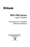
DES-3226S
Layer 2 Switch
Command Line Interface Reference Manual
Third Edition (December 2003)
651E3226S055
Printed In Taiwan
RECYCLABLE
DES-3226S Layer 2 Switch CLI Reference
D-Link Offices for Registration and Warranty Service
The product's Registration Card, provided at the back of this manual, must be sent to a
D-Link office. To obtain an RMA number for warranty service as to a hardware
product, or to obtain warranty service as to a software product, contact the D-Link
office nearest you. An address/telephone/fax/e-mail/Web site list of D-Link offices is
provided in the back of this manual.
Trademarks
Copyright 2003 D-Link Corporation.
Contents subject to change without prior notice.
D-Link is a registered trademark of D-Link Corporation/D-Link Systems, Inc. All other
trademarks belong to their respective proprietors.
Copyright Statement
No part of this publication may be reproduced in any form or by any means or used to
make any derivative such as translation, transformation, or adaptation without
permission from D-Link Corporation/D-Link Systems Inc., as stipulated by the United
States Copyright Act of 1976.
i
DES-3226S Layer 2 Switch CLI Reference
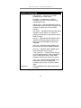
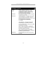
FCC Warning
This equipment has been tested and found to comply with the limits for a Class
A digital device, pursuant to Part 15 of the FCC Rules. These limits are
designed to provide reasonable protection against harmful interference when
the equipment is operated in a commercial environment. This equipment
generates, uses, and can radiate radio frequency energy and, if not installed
and used in accordance with this user’s guide, may cause harmful interference
to radio communications. Operation of this equipment in a residential area is
likely to cause harmful interference in which case the user will be required to
correct the interference at his own expense.
CE Mark Warning
This is a Class A product. In a domestic environment, this product may cause
radio interference in which case the user may be required to take adequate
measures.
VCCI Warning
ii
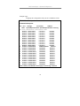
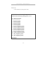
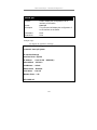
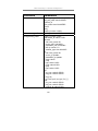
Table of Contents
Introduction ....................................................................................................... 1
Using the Console CLI...................................................................................... 5
Command Syntax ............................................................................................ 12
Basic Switch Commands................................................................................. 17
Switch Port Commands................................................................................... 36
Port Security Commands................................................................................. 40
Network Management (SNMP) Commands ................................................... 46
MAC Notification Commands ........................................................................ 74
Download/Upload Commands ........................................................................ 82
Network Monitoring Commands .................................................................... 86
Spanning Tree Commands ............................................................................ 109
Forwarding Database Commands ................................................................. 121
Broadcast Storm Control Commands............................................................ 138
QOS Commands............................................................................................ 142
Port Mirroring Commands ............................................................................ 161
VLAN Commands......................................................................................... 168
Link Aggregation Commands ....................................................................... 181
Basic IP Commands ...................................................................................... 194
IGMP Snooping Commands ......................................................................... 198
802.1X Commands........................................................................................ 213
Access Control List (ACL) Commands ........................................................ 239
Traffic Segmentation Commands.................................................................. 254
Stacking Commands...................................................................................... 259
Time and SNTP Commands.......................................................................... 264
Asymmetric VLANs Commands ...................................................................276
Command History List...................................................................................281
Technical Specifications ................................................................................286
DES-3226S Layer 2 Switch CLI Reference
1
I NTRODUCTION
The DES-3226 Switch can be managed through the switch’s serial port,
Telnet, or the Web-based management agent. The Command Line Interface
(CLI) can be used to configure and manage the switch via the serial port or
Telnet interfaces.
This manual provides a reference for all of the commands contained in the
CLI. Configuration and management of the switch via the Web-based
management agent is discussed in the User’s Guide.
Accessing the Switch via the Serial Port
The switch’s serial port’s default settings are as follows:
•
9600 baud
•
no parity
•
8 data bits
•
1 stop bit
A computer running a terminal emulation program capable of emulating a VT100 terminal and a serial port configured as above is then connected to the
switch’s serial port via an RS-232 DB-9 cable.
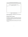
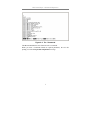
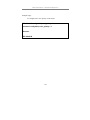
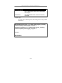
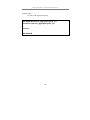
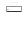
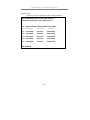
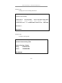
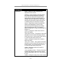
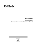
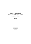
With the serial port properly connected to a management computer, the
following screen should be visible. If this screen does not appear, try pressing
Ctrl+r to refresh the console screen.
1
DES-3226S Layer 2 Switch CLI Reference
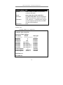
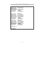
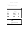
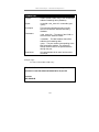
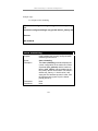
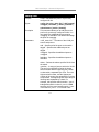
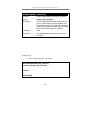
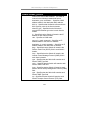
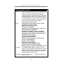
Figure 1-1. Initial CLI screen
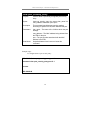
There is no initial username or password. Just press the Enter key twice to
display the CLI input cursor − DES-3226S:4#. This is the command line
where all commands are input.
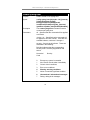
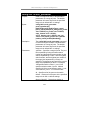
Setting the Switch’s IP Address
Each Switch must be assigned its own IP Address, which is used for
communication with an SNMP network manager or other TCP/IP application
(for example BOOTP, TFTP). The switch’s default IP address is 10.90.90.90.
You can change the default Switch IP address to meet the specification of your
networking address scheme.
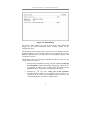
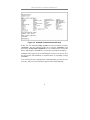
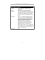
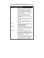
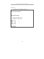
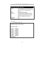
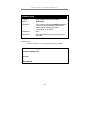
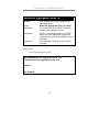
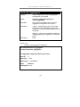
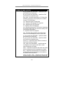
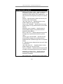
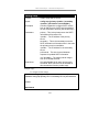
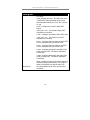
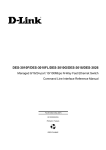
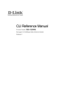
The switch is also assigned a unique MAC address by the factory. This MAC
address cannot be changed, and can be found on the initial boot console screen
– shown below.
2
DES-3226S Layer 2 Switch CLI Reference
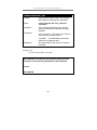
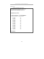
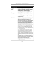
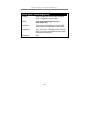
Figure 1-2. Boot Screen
The switch’s MAC address can also be found in the Web management
program on the Switch Information (Basic Settings) window on the
Configuration menu.
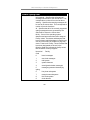
The IP address for the switch must be set before it can be managed with the
Web-based manager. The switch IP address can be automatically set using
BOOTP or DHCP protocols, in which case the actual address assigned to the
switch must be known.
The IP address may be set using the Command Line Interface (CLI) over the
console serial port as follows:
1.
Starting at the command line prompt, enter the commands config ipif
System ipaddress xxx.xxx.xxx.xxx/yyy.yyy.yyy.yyy. Where the x’s
represent the IP address to be assigned to the IP interface named
System and the y’s represent the corresponding subnet mask.
2.
Alternatively, you can enter config ipif System ipaddress
xxx.xxx.xxx.xxx/z. Where the x’s represent the IP address to be
assigned to the IP interface named System and the z represents the
corresponding number of subnets in CIDR notation.
3
DES-3226S Layer 2 Switch CLI Reference
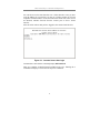
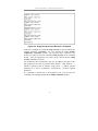
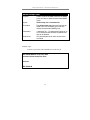
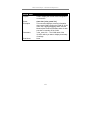
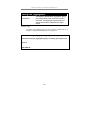
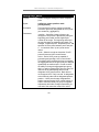
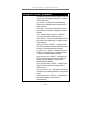
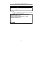
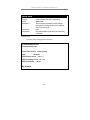
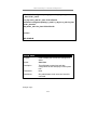
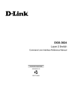
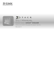
The IP interface named System on the switch can be assigned an IP address
and subnet mask which can then be used to connect a management station to
the switch’s Telnet or Web-based management agent.
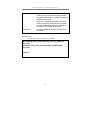
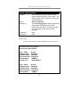
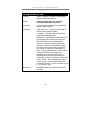
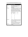
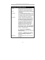
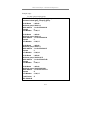
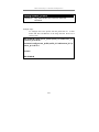
Figure 1-3. Assigning an IP Address
In the above example, the switch was assigned an IP address of 10.41.44.2
with a subnet mask of 255.0.0.0. The system message Success indicates that
the command was executed successfully. The switch can now be configured
and managed via Telnet and the CLI or via the Web-based management agent
using the above IP address to connect to the switch.
4
DES-3226S Layer 2 Switch CLI Reference
2
U SING THE C ONSOLE CLI
The DES-3226S supports a console management interface that allows the user
to connect to the switch’s management agent via a serial port and a terminal or
a computer running a terminal emulation program. The console can also be
used over the network using the TCP/IP Telnet protocol. The console program
can be used to configure the switch to use an SNMP-based network
management software over the network.
This chapter describes how to use the console interface to access the switch,
change its settings, and monitor its operation.
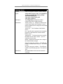
Note: Switch configuration settings are saved to nonvolatile RAM using the save command. The current
configuration will then be retained in the switch’s NVRAM, and reloaded when the switch is rebooted. If the
switch is rebooted without using the save command, the
last configuration saved to NV-RAM will be loaded.
Connecting to the Switch
The console interface is used by connecting the Switch to a VT100-compatible
terminal or a computer running an ordinary terminal emulator program (e.g.,
the HyperTerminal program included with the Windows operating system)
using an RS-232C serial cable. Your terminal parameters will need to be set
to:
•
VT-100 compatible
•
9,600 baud
•
8 data bits
•
No parity
•
One stop bit
•
No flow control
5
DES-3226S Layer 2 Switch CLI Reference
You can also access the same functions over a Telnet interface. Once you have
set an IP address for your Switch, you can use a Telnet program (in VT-100
compatible terminal mode) to access and control the Switch. All of the screens
are identical, whether accessed from the console port or from a Telnet
interface.
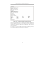
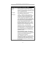
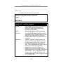
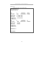
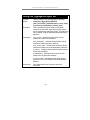
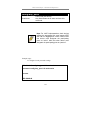
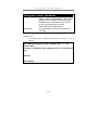
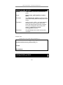
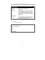
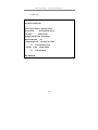
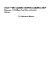
After the switch reboots and you have logged in, the console looks like this:
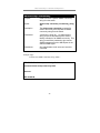
Figure 2-1. Console Screen after login
Commands are entered at the command prompt, DES-3226S:4#.
There are a number of helpful features included in the CLI. Entering the ?
command will display a list of all of the top-level commands.
6
DES-3226S Layer 2 Switch CLI Reference
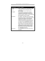
Figure 2-2. The ? Command
The dir command has the same function as the ? command.
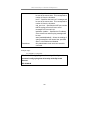
When you enter a command without its required parameters, the CLI will
prompt you with a Next possible completions: message.
7
DES-3226S Layer 2 Switch CLI Reference
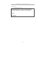
Figure 2-3. Example Command Parameter Help
In this case, the command config account was entered with the parameter
<username>. The CLI will then prompt you to enter the <username> with
the message, Next possible completions:. Every command in the CLI has this
feature, and complex commands have several layers of parameter prompting.
In addition, after typing any given command plus one space, you can see all of
the next possible sub-commands, in sequential order, by repeatedly pressing
the Tab key.
To re-enter the previous command at the command prompt, press the up arrow
cursor key. The previous command will appear at the command prompt.
8
DES-3226S Layer 2 Switch CLI Reference
Figure 2-4. Using the Up Arrow to Re-enter a Command
In the above example, the command config account was entered without the
required parameter <username>, the CLI returned the Next possible
completions: <username> prompt. The up arrow cursor control key was
pressed to re-enter the previous command (config account) at the command
prompt. Now the appropriate User name can be entered and the config
account command re-executed.
All commands in the CLI function in this way. In addition, the syntax of the
help prompts are the same as presented in this manual − angle brackets < >
indicate a numerical value or character string, braces { } indicate optional
parameters or a choice of parameters, and brackets [ ] indicate required
parameters.
If a command is entered that is unrecognized by the CLI, the top-level
commands will be displayed under the Available commands: prompt.
9
DES-3226S Layer 2 Switch CLI Reference
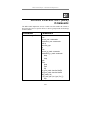
Figure 2-5. The Next Available Commands Prompt
The top-level commands consist of commands such as show or config. Most
of these commands require one or more parameters to narrow the top-level
command. This is equivalent to show what? or config what? Where the what?
is the next parameter.
For example, if you enter the show command with no additional parameters,
the CLI will then display all of the possible next parameters.
10
DES-3226S Layer 2 Switch CLI Reference
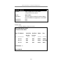
Figure 2-6. Next possible completions: Show Command
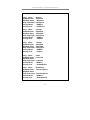
In the above example, all of the possible next parameters for the show
command are displayed. At the next command prompt, the up arrow was used
to re-enter the show command, followed by the account parameter. The CLI
then displays the user accounts configured on the switch.
11
DES-3226S Layer 2 Switch CLI Reference
3
C OMMAND S YNTAX
The following symbols are used to describe how command entries are made
and values and arguments are specified in this manual. The online help
contained in the CLI and available through the console interface uses the same
syntax.
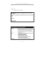
Note: All commands are case-sensitive. Be sure
to disable Caps Lock or any other unwanted
function that changes text case.
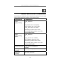
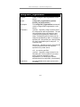
<angle brackets>
Purpose
Encloses a variable or value that must be
specified.
Syntax
create ipif <ipif_name> vlan <vlan_name 32>
ipaddress <network_address>
Description
In the above syntax example, you must supply
an IP interface name in the <ipif_name> space,
a VLAN name in the <vlan_name 32> space,
and the network address in the
<network_address> space. Do not type the
angle brackets.
Example
Command
create ipif Engineering vlan Design
ipaddress 10.24.22.5/255.0.0.0
12
DES-3226S Layer 2 Switch CLI Reference
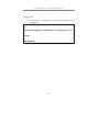
[square brackets]
Purpose
Encloses a required value or set of required
arguments. One value or argument can be
specified.
Syntax
create account [admin|user]
Description
In the above syntax example, you must specify
either an admin or a user level account to be
created. Do not type the square brackets.
Example
Command
create account admin
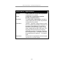
| vertical bar
Purpose
Separates two or more mutually exclusive items
in a list, one of which must be entered.
Syntax
show snmp [community|detail]
Description
In the above syntax example, you must specify
either community, or detail. Do not type the
backslash.
Example
Command
show snmp community
13
DES-3226S Layer 2 Switch CLI Reference
{braces}
Purpose
Encloses an optional value or set of optional
arguments.
Syntax
reset {[config|system]}
Description
In the above syntax example, you have the
option to specify config or detail. It is not
necessary to specify either optional value,
however the effect of the system reset is
dependent on which, if any, value is specified.
Therefore, with this example there are three
possible outcomes of performing a system
reset. See the following chapter, Basic
Commands for more details about the reset
command.
Example
command
reset config
14
DES-3226S Layer 2 Switch CLI Reference
Line Editing Key Usage
Delete
Backspace
Left Arrow
Right Arrow
Up Arrow
Down Arrow
Tab
Deletes the character under the cursor and then
shifts the remaining characters in the line to the
left.
Deletes the character to the left of the cursor
and shifts the remaining characters in the line to
the left.
Moves the cursor to the left.
Moves the cursor to the right.
Repeat the previously entered command. Each
time the up arrow is pressed, the command
previous to that displayed appears. This way it
is possible to review the command history for
the current session. Use the down arrow to
progress sequentially forward through the
command history list.
The down arrow will display the next command
in the command history entered in the current
session. This displays each command
sequentially as it was entered. Use the up arrow
to review previous commands.
Shifts the cursor to the next field to the left.
Multiple Page Display Control Keys
Space
Displays the next page.
15
DES-3226S Layer 2 Switch CLI Reference
CTRL+c
ESC
n
p
q
r
a
Enter
Stops the display of remaining pages when
multiple pages are to be displayed.
Stops the display of remaining pages when
multiple pages are to be displayed.
Displays the next page.
Displays the previous page.
Stops the display of remaining pages when
multiple pages are to be displayed.
Refreshes the pages currently displayed.
Displays the remaining pages without pausing
between pages.
Displays the next line or table entry.
16
DES-3226S Layer 2 Switch CLI Reference
4
B ASIC S WITCH C OMMANDS
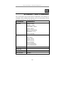
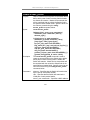
The basic switch commands in the Command Line Interface (CLI) are listed
(along with the appropriate parameters) in the following table.
Command
Parameters
create account
[admin|user]
<username>
config account
<username>
show account
show session
show switch
show serial_port
config serial_port
baud_rate [9600|19200|38400|115200]
auto_logout [never|2_minutes|5_minutes
|10_minutes|15_minutes]
enable clipaging
disable clipaging
enable telnet
<tcp_port_number>
disable telnet
enable web
<tcp_port_number>
disable web
save
reboot
reset
{[config|system]}
login
logout
Each command is listed, in detail, in the following sections.
17
DES-3226S Layer 2 Switch CLI Reference
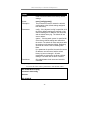
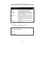
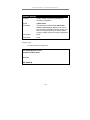
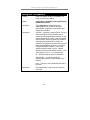
create account
Purpose
Used to create user accounts
Syntax
create [admin|user] <username>
Description
The create account command is used to create
user accounts that consist of a username of 1 to
15 characters and a password of 0 to 15
characters. Up to 8 user accounts can be
created.
Parameters
Admin <username>
User <username>
Restrictions
Only Administrator-level users can issue this
command.
Usernames can be between 1 and 15
characters.
Passwords can be between 0 and 15
characters.
Example usage:
To create an administrator-level user account with the username
“dlink”.
DES-3226S:4#create account admin dlink
Command: create account admin dlink
Enter a case-sensitive new password:****
Enter the new password again for confirmation:****
Success.
DES-3226S:4#
18
DES-3226S Layer 2 Switch CLI Reference
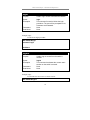
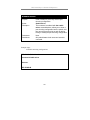
config account
Purpose
Used to configure user accounts
Syntax
config account <username>
Description
The config account command configures a
user account that has been created using the
create account command.
Parameters
<username>
Restrictions
Only Administrator-level users can issue this
command.
Usernames can be between 1 and 15
characters.
Passwords can be between 0 15 characters.
Example usage:
To configure the user password of “dlink” account:
DES-3226S:4#config account dlink
Command: config account dlink
Enter a old password:****
Enter a case-sensitive new password:****
Enter the new password again for confirmation:****
Success.
DES-3226S:4#
19
DES-3226S Layer 2 Switch CLI Reference
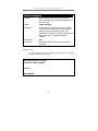
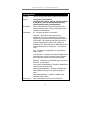
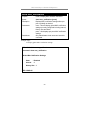
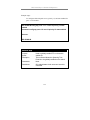
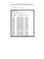
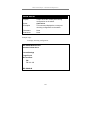
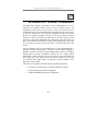
show account
Purpose
Used to display user accounts
Syntax
show account
Description
Displays all user accounts created on the
switch. Up to 8 user accounts can exist on the
switch at one time.
Parameters
None.
Restrictions
None.
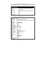
Example usage:
To display the accounts that have been created:
DES-3226S:4#show account
Command: show account
Current Accounts:
Username
--------------dlink
Access Level
-----------Admin
DES-3226S:4#
20
DES-3226S Layer 2 Switch CLI Reference
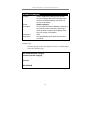
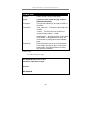
delete account
Purpose
Used to delete an existing user account
Syntax
delete account <username>
Description
The delete account command deletes a user
account that has been created using the create
account command.
Parameters
<username>
Restrictions
Only Administrator-level users can issue this
command.
Example usage:
To delete the user account “System”:
DES-3226S:4#delete account System
Command: delete account System
Success.
DES-3226S:4#
21
DES-3226S Layer 2 Switch CLI Reference
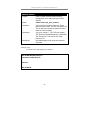
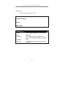
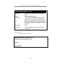
show session
Purpose
Used to display a list of currently logged-in
users.
Syntax
show session
Description
This command displays a list of all the users
that are logged-in at the time the command is
issued.
Parameters
None
Restrictions
None.
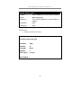
Example usage:
To display the way that the users logged in:
DES-3226S:4#show session
Command: show session
ID Login Time
Live Time
From
Level Name
-- ------------------- ------------ --------------- ----- --------------*8 00000 days 03:36:27 0:0:20.260
22
Serial Port
4
Anonymous
DES-3226S Layer 2 Switch CLI Reference
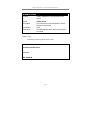
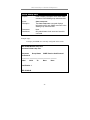
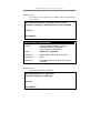
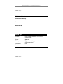
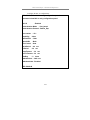
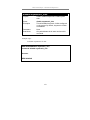
show switch
Purpose
Used to display information about the switch.
Syntax
show switch
Description
This command displays information about the
switch.
Parameters
None.
Restrictions
None.
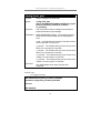
Example usage:
To display the switch information:
DES-3226S:4#show switch
Command: show switch
Device Type
: DES-3226S Fast-Ethernet Switch
Module Type
: DES-332GS 1-port GBIC Gigabit Ethernet and 1 Stacking Port
Unit ID
:1
MAC Address
: DA-10-21-00-00-01
IP Address
: 10.41.44.22 (Manual)
VLAN Name
: default
Subnet Mask
: 255.0.0.0
Default Gateway : 0.0.0.0
Boot PROM Version : Build 0.00.001
Firmware Version : Build 4.00-B30
Hardware Version : 1B1
Device S|N
:
System Name
: DES-3226S_#3
System Location : 7th_flr_east_cabinet
System Contact
: Julius_Erving_212-555-6666
Spanning Tree
: Disabled
GVRP
: Disabled
IGMP Snooping
: Disabled
TELNET
: Enabled (TCP 23)
WEB
: Enabled (TCP 80)
RMON
: Enabled
Asymmetric VLAN : Enabled
DES-3226S:4#
23
DES-3226S Layer 2 Switch CLI Reference
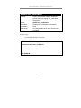
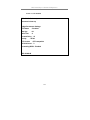
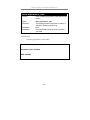
show serial_port
Purpose
Used to display the current serial port settings.
Syntax
show serial_port
Description
This command displays the current serial port
settings.
Parameters
None.
Restrictions
None
Example usage:
To display the serial port setting:
DES-3226S:4#show serial_port
Command: show serial_port
Baud Rate
: 9600
Data Bits
:8
Parity Bits
: None
Stop Bits
:1
Auto-Logout
: 10 mins
DES-3226S:4#
24
DES-3226S Layer 2 Switch CLI Reference
config serial_port
Purpose
Used to configure the serial port.
Syntax
config serial_port
{baud_rate[9600|19200|38400|115200]|auto_logout
[never|2_minutes|5_minutes|10_minutes|
15_minutes]}
Description
This command is used to configure the serial port’s
baud rate and auto logout settings.
Parameters
[9600|19200|38400|115200] − The serial bit rate that
will be used to communicate with the management
host.
never − No time limit on the length of time the console
can be open with no user input.
2_minutes − The console will log out the current user if
there is no user input for 2 minutes.
5_minutes − The console will log out the current user if
there is no user input for 5 minutes.
10_minutes − The console will log out the current user
if there is no user input for 10 minutes.
15_minutes − The console will log out the current user
if there is no user input for 15 minutes.
Restrictions
Only administrator-level users can issue this
command.
Example usage:
To configure baud rate:
DES-3226S:4#config serial_port baud_rate 9600
Command: config serial_port baud_rate 9600
Success.
DES-3226S:4#
25
DES-3226S Layer 2 Switch CLI Reference
enable clipaging
Purpose
Used to pause the scrolling of the console
screen when the show command displays more
than one page.
Syntax
enable clipaging
Description
This command is used when issuing the show
command which causes the console screen to
rapidly scroll through several pages. This
command will cause the console to pause at the
end of each page. The default setting is
enabled.
Parameters
None.
Restrictions
Only administrator-level users can issue this
command.
Example usage:
To enable pausing of the screen display when the show command
output reaches the end of the page:
DES-3226S:4#enable clipaging
Command: enable clipaging
Success.
DES-3226S:4#
26
DES-3226S Layer 2 Switch CLI Reference
disable clipaging
Purpose
Used to disable the pausing of the console
screen scrolling at the end of each page when
the show command displays more than one
screen of information.
Syntax
disable clipaging
Description
This command is used to disable the pausing of
the console screen at the end of each page
when the show command would display more
than one screen of information.
Parameters
None.
Restrictions
Only administrator-level users can issue this
command.
Example usage:
To disable pausing of the screen display when show command output
reaches the end of the page:
DES-3226S:4#disable clipaging
Command: disable clipaging
Success.
DES-3226S:4#
27
DES-3226S Layer 2 Switch CLI Reference
enable telnet
Purpose
Used to enable communication with and
management of the switch using the Telnet
protocol.
Syntax
enable telnet <tcp_port_number>
Description
This command is used to enable the Telnet
protocol on the switch. The user can specify the
TCP or UDP port number the switch will use to
listen for Telnet requests.
Parameters
<tcp_port_number> − The TCP port number.
TCP ports are numbered between 1 and 65535.
The “well-known” TCP port for the Telnet
protocol is 23.
Restrictions
Only administrator-level users can issue this
command.
Example usage:
To enable Telnet and configure port number:
DES-3226S:4#enable telnet 23
Command: enable telnet 23
Success.
DES-3226S:4#
28
DES-3226S Layer 2 Switch CLI Reference
disable telnet
Purpose
Used to disable the Telnet protocol on the
switch.
Syntax
disable telnet
Description
This command is used to disable the Telnet
protocol on the switch.
Parameters
None.
Restrictions
Only administrator-level users can issue this
command.
Example usage:
To disable the Telnet protocol on the switch:
DES-3226S:4#disable telnet
Command: disable telnet
Success.
DES-3226S:4#
29
DES-3226S Layer 2 Switch CLI Reference
enable web
Purpose
Used to enable the HTTP-based management
software on the switch.
Syntax
enable web <tcp_port_number>
Description
This command is used to enable the Webbased management software on the switch.
The user can specify the TCP port number the
switch will use to listen for Telnet requests.
Parameters
<tcp_port_number> − The TCP port number.
TCP ports are numbered between 1 and 65535.
The “well-known” port for the Web-based
management software is 80.
Restrictions
Only administrator-level users can issue this
command.
Example usage:
To enable HTTP and configure port number:
DES-3226S:4#enable web 80
Command: enable web 80
Success.
DES-3226S:4#
30
DES-3226S Layer 2 Switch CLI Reference
disable web
Purpose
Used to disable the HTTP-based management
software on the switch.
Syntax
disable web
Description
This command disables the Web-based
management software on the switch.
Parameters
None.
Restrictions
Only administrator-level users can issue this
command.
Example usage:
To disable HTTP:
DES-3226S:4#disable web
Command: disable web
Success.
DES-3226S:4#
31
DES-3226S Layer 2 Switch CLI Reference
save
Purpose
Used to save changes in the switch’s
configuration to non-volatile RAM.
Syntax
Save
Description
This command is used to enter the current
switch configuration into non-volatile RAM. The
saved switch configuration will be loaded into
the switch’s memory each time the switch is
restarted.
Parameters
None.
Restrictions
Only administrator-level users can issue this
command.
Example usage:
To save the switch’s current configuration to non-volatile RAM:
DES-3226S:4#save
Command: save
Saving all settings to NV-RAM... 100%
done.
DES-3226S:4#
32
DES-3226S Layer 2 Switch CLI Reference
reboot
Purpose
Used to restart the switch.
Syntax
reboot
Description
This command is used to restart the switch.
Parameters
None.
Restrictions
None.
Example usage:
To restart the switch:
DES-3226S:4#reboot
Command: reboot
Are you sure want to proceed with the system reboot? (y|n)
Please wait, the switch is rebooting...
33
DES-3226S Layer 2 Switch CLI Reference
reset
Purpose
Used to reset the switch to the factory default
settings.
Syntax
reset {[config|system]}
Description
This command is used to restore the switch’s
configuration to the default settings assigned
from the factory.
Parameters
config − If the keyword ‘config’ is specified, all of
the factory default settings are restored on the
switch including the IP address, user accounts,
and the switch history log. The switch will not
save or reboot.
system − If the keyword ‘system’ is specified all
of the factory default settings are restored on
the switch. The switch will save and reboot after
the settings are changed to default. Rebooting
will clear all entries in the Forwarding Data
Base.
If no parameter is specified, the switch’s current
IP address, user accounts, and the switch
history log are not changed. All other
parameters are restored to the factory default
settings. The switch will not save or reboot.
Restrictions
Only administrator-level users can issue this
command.
Example usage:
To restore all of the switch’s parameters to their default values:
DES-3226S:4#reset config
Command: reset config
Success.
DES-3226S:4#
34
DES-3226S Layer 2 Switch CLI Reference
login
Purpose
Used to log in a user to the switch’s console.
Syntax
login
Description
This command is used to initiate the login
procedure. The user will be prompted for his
Username and Password.
Parameters
None.
Restrictions
None.
Example usage:
To initiate the login procedure:
DES-3226S:4#login
Command: login
UserName:
logout
Purpose
Used to log out a user from the switch’s
console.
Syntax
logout
Description
This command terminates the current user’s
session on the switch’s console.
Parameters
None.
Restrictions
None.
Example usage:
To terminate the current user’s console session:
DES-3226S:4#logout
35
DES-3226S Layer 2 Switch CLI Reference
5
S WITCH P ORT C OMMANDS
The switch port commands in the Command Line Interface (CLI) are listed
(along with the appropriate parameters) in the following table.
Command
Parameters
config ports
<portlist|all>
speed [auto|10_half|10_full|100_half|100_full|
1000_half|1000_full]
flow_control [enable|disable]
learning [enable|disable]
state [enable|disable]
show ports
<portlist>
Each command is listed, in detail, in the following sections.
36
DES-3226S Layer 2 Switch CLI Reference
config ports
Purpose
Used to configure the switch’s Ethernet port settings.
Syntax
config ports [<portlist|all>]
{speed[auto|10_half|10_full|100_half|100_half|100
0_full] flow_control [enable|disable] learning
[enable|disable] state [enable|disable]}
Description
This command allows for the configuration of the
switch’s Ethernet ports. Only the ports listed in the
<portlist> will be affected.
Parameters
all − Configure all ports on the switch.
<portlist> − Specifies a range of ports to be
configured. The port list is specified by listing the
beginning port number and the highest port number
of the range. The beginning and end of the port list
range are separated by a dash. For example, 3
specifies port 3. 4 specifies port 4. 3-4 specifies all of
the ports between port 3 and port 4 − in numerical
order.
auto − Enables auto-negotiation for the specified
range of ports.
[10|100|1000] − Configures the speed in Mbps for the
specified range of ports. Gigabit ports are statically
set to 1000 and cannot be set to slower speeds.
[half|full] − Configures the specified range of ports as
either full- or half-duplex.
flow_control [enable|disable] – Enable or disable flow
control for the specified ports.
learning [enable|disable] − Enables or disables the
MAC address learning on the specified range of
ports.
state [enable|disable] − Enables or disables the
specified range of ports.
Restrictions
Only administrator-level users can issue this
37
DES-3226S Layer 2 Switch CLI Reference
config ports
command.
Example usage:
To configure the speed of port 3 to be 10 Mbps, full duplex, learning
and state enabled:
DES-3226S:4#config ports 1-3 speed 10_full learning enable state enable
Command: config ports 1-3 speed 10_full learning enable state enable
Success.
DES-3226S:4#
show ports
Purpose
Used to display the current configuration of a
range of ports.
Syntax
show ports {<portlist>}
Description
This command is used to display the current
configuration of a range of ports.
Parameters
<portlist> − Specifies a range of ports to be
displayed. The port list is specified by listing the
beginning port number and the highest port
number of the range. The beginning and end of
the port list range are separated by a dash. For
example, 3 specifies port 3. 4 specifies port 4.
3-4 specifies all of the ports between port 3 and
port 4 − in numerical order.
Restrictions
None.
38
DES-3226S Layer 2 Switch CLI Reference
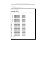
Example usage:
To display the configuration of all ports an a standalone switch:
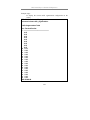
DES-3226S:4#show ports
Command show ports:
Port
Port
Settings
Connection
Address
State Speed/Duplex/FlowCtrl Speed/Duplex/FlowCtrl Learning
------ -------- --------------------- --------------------- -------1
Enabled Auto/Enabled
Link Down
Enabled
2
Enabled Auto/Enabled
Link Down
Enabled
3
Enabled Auto/Enabled
Link Down
Enabled
4
Enabled Auto/Enabled
Link Down
Enabled
5
Enabled Auto/Enabled
Link Down
Enabled
6
Enabled Auto/Enabled
Link Down
Enabled
7
Enabled Auto/Enabled
Link Down
Enabled
8
Enabled Auto/Enabled
Link Down
Enabled
9
Enabled Auto/Enabled
Link Down
Enabled
10
Enabled Auto/Enabled
100M/Full/802.3x
Enabled
11
Enabled Auto/Enabled
Link Down
Enabled
12
Enabled Auto/Enabled
Link Down
Enabled
13
Enabled Auto/Disabled
Link Down
Enabled
14
Enabled Auto/Disabled
Link Down
Enabled
15
Enabled Auto/Disabled
Link Down
Enabled
16
Enabled Auto/Disabled
Link Down
Enabled
17
Enabled Auto/Disabled
Link Down
Enabled
18
Enabled Auto/Disabled
Link Down
Enabled
19
Enabled Auto/Disabled
Link Down
Enabled
20
Enabled Auto/Disabled
Link Down
Enabled
CTRL+C ESC q Quit SPACE n Next Page p Previous Page r Refresh
39
DES-3226S Layer 2 Switch CLI Reference
6
P ORT S ECURITY C OMMANDS
The switch port security commands in the Command Line Interface (CLI) are
listed (along with the appropriate parameters) in the following table.
Command
Parameters
config port_security
ports
[<portlist>| all ] {admin_state [enable | disable]
|max_learning_addr <max_lock_no 0-10> |
lock_address_mode[Permanent|
DeleteOnTimeout|DeleteOnReset]}
clear
port_security_entry
vlan_name <vlan_name 32> mac_address
<macaddr> port <port>
show port_security
{ports <portlist>}
Each command is listed, in detail, in the following sections.
40
DES-3226S Layer 2 Switch CLI Reference
config port_security ports
Purpose
Used to configure port security settings.
Syntax
config port_security ports [ <portlist>| all ]
{admin_state [enable | disable] |
max_learning_addr <max_lock_no 0-10> |
lock_address_mode
[Permanent|DeleteOnTimeout|DeleteOnReset]}
Description
This command allows for the configuration of the port
security feature. Only the ports listed in the <portlist>
are effected.
Parameters
portlist − specifies a range of ports to be configured.
The port list is specified by listing the lowest switch
number and the beginning port number on that
switch, separated by a colon. Then the highest
switch number, and the highest port number of the
range (also separated by a colon) are specified. The
beginning and end of the port list range are seperated
by a dash. For example, 1:3 specifies switch number
1, port 3. 2:4 specifies switch number 2, port 4. 1:32:4 specifies all of the ports between switch 1, port 3
and switch 2, port 4 − in numerical order.
all − configure port security for all ports on the switch.
admin_state [enable|disable] – enable or disable port
security for the listed ports.
max_learning_addr <1-10> - use this to limit the
number of MAC addresses dynamically listed in the
FDB for the ports.
lock_address_mode[DeleteOnTimout|DeleteOnReset
] – delete FDB dynamic entries for the ports on
timeout of the FDB (see Forwarding Database
Commands). Specify DeleteOnReset to delete all
FDB entries, including static entries upon system
reset or rebooting.
Restrictions
Only administrator-level users can issue this
command.
41
DES-3226S Layer 2 Switch CLI Reference
Example usage:
To configure the port security:
DES-3226S:4#config port_security ports 5:1-5:5 admin_state enable
max_learning_addr 5 lock_address_mode Permanent
Command: config port_security ports 5:1-5:5 admin_state enable
max_learning_addr 5 lock_address_mode Permanent
Stacking port 5:5 can not be a port-security port
DES-3226S:4#
42
DES-3226S Layer 2 Switch CLI Reference
clear port_security_entry
Purpose
Used to delete a previously configured port security
entry.
Syntax
clear port_security_entry vlan_name <vlan_name 32>
mac_address <macaddr> port <port>.
Description
This command can delete port security settings
according to specified VLAN, MAC address and port.
Parameters
vlan_name – The name of the VLAN to which the port
belongs.
mac_address – The MAC address being deleted from
the FDB for the port.
port – The port number associated with the MAC
address in the FDB.
Restrictions
Only administrator-level users can issue this
command.
Example usage:
To configure delete a port security entry:
DES-3226S:4#clear port_security_entry port 15:1
Command: clear port_security_entry port 15:1
Success.
DES-3226S:4#
43
DES-3226S Layer 2 Switch CLI Reference
show port_security
Purpose
Used to display the current port security
configuration.
Syntax
show port_security {ports <portlist>}
Description
This command is used to display port security
information of the switch ports. The information
displayed includes port security admin state,
maximum number of learning address and lock
mode.
Parameters
<portlist> − specifies a range of ports to be
viewed. The port list is specified by listing the
lowest switch number and the beginning port
number on that switch, separated by a colon.
Then the highest switch number, and the
highest port number of the range (also
separated by a colon) are specified. The
beginning and end of the port list range are
seperated by a dash. For example, 1:3
specifies switch number 1, port 3. 2:4 specifies
switch number 2, port 4. 1:3-2:4 specifies all of
the ports between switch 1, port 3 and switch 2,
port 4 − in numerical order.
Restrictions
None.
44
DES-3226S Layer 2 Switch CLI Reference
Example usage:
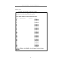
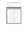
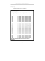
To display the port security configuration:
DES-3226S:4#show port_security ports 1-24
Command: show port_security ports 1-24
Port# Admin State Max. Learning Addr. Lock Address Mode
---- ----------- ------------------- ----------------1
Disabled
1
DeleteOnReset
2
Disabled
1
DeleteOnReset
3
Disabled
1
DeleteOnReset
4
Disabled
1
DeleteOnReset
5
Disabled
1
DeleteOnReset
6
Disabled
1
DeleteOnReset
7
Enabled
10
DeleteOnReset
8
Disabled
1
DeleteOnReset
9
Disabled
1
DeleteOnReset
10 Disabled
1
DeleteOnReset
11 Disabled
1
DeleteOnReset
12 Disabled
1
DeleteOnReset
13 Disabled
1
DeleteOnReset
14 Disabled
1
DeleteOnReset
15 Disabled
1
DeleteOnReset
16 Disabled
1
DeleteOnReset
17 Disabled
1
DeleteOnReset
18 Disabled
1
DeleteOnReset
19 Disabled
1
DeleteOnReset
20 Disabled
1
DeleteOnReset
CTRL+C ESC q Quit SPACE n Next Page p Previous Page r
Refresh
45
DES-3226S Layer 2 Switch CLI Reference
7
N ETWORK M ANAGEMENT (SNMP)
C OMMANDS
The network management commands in the Command Line Interface (CLI)
are listed (along with the appropriate parameters) in the following table.
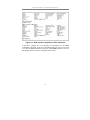
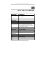
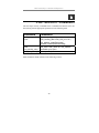
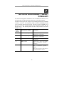
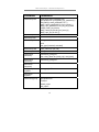
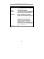
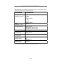
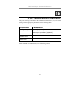
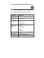
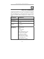
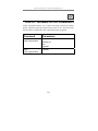
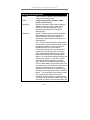
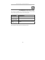
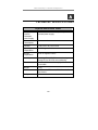
The DES-3226S supports the Simple Network Management Protocol (SNMP)
versions 1, 2c, and 3. You can specify which version of the SNMP you want
to use to monitor and control the switch. The three versions of SNMP vary in
the level of security provided between the management station and the
network device. The following table lists the security features of the three
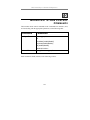
SNMP versions:
SNMP
Version
Authentication Method
Description
v1
Community String
Community
String
is
used
authentication − NoAuthNoPriv
for
v2c
Community String
Community
String
is
used
authentication − NoAuthNoPriv
for
v3
Username
Username is used for authentication −
NoAuthNoPriv
v3
MD5 or SHA
Authentication is based on the HMACMD5 or HMAC-SHA algorithms −
AuthNoPriv
v3
MD5 DES or SHA DES
Authentication is based on the HMACMD5 or HMAC-SHA algorithms −
AuthPriv.
DES 56-bit encryption is added based on
the CBC-DES (DES-56) standard
46
DES-3226S Layer 2 Switch CLI Reference
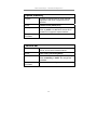
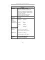
Command
Parameters
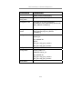
create snmp user
create snmp user <username 32>
<groupname 32> {encrypted(1) [by_password(1)
auth [md5(2) <auth_password 8-16 > |
sha(3) <auth_password 8-20 >] priv [none(1) |
des(2) <priv_password 8-16>] | by_key(2) auth
[md5(2) <auth_key 32-32>|
sha(3) <auth_key 40-40>] priv [none(1) |
des(2) <priv_key 32-32> ]]}
delete snmp user
<username 32>
show snmp user
create snmp view
<view_name 32>
<oid>
view_type [included | excluded]
delete snmp view
<view_name 32> [all | oid]
show snmp view
<view_name 32>
create snmp
community
<community_string 32>
delete snmp
community
<community_string 32>
view <view_name 32> [read_only | read_write]
show snmp
community
config snmp
engineID
<snmp_engineID>
show snmp
engineID
create snmp group
<groupname 32>
v1|v2c|v3
noauth_nopriv
auth_nopriv
47
DES-3226S Layer 2 Switch CLI Reference
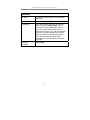
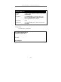
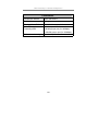
Command
Parameters
auth_priv
read_view <view_name 32>
write_view <view_name 32>
notify_view <view_name 32>
delete snmp group
<groupname 32>
show snmp groups
create snmp host
<ipaddr>
v1|v2c|v3
noauth_nopriv
auth_nopriv
auth_priv <auth_string 32>
delete snmp host
<ipaddr>
show snmp host
<ipaddr>
config
mac_notification
ports <portlist>|all
interval <int 1-2147483647>
historysize <int 1 - 500>
enable
mac_notification
disable
mac_notification
show
mac_notification
{ports}
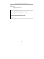
Each command is listed, in detail, in the following sections.
48
DES-3226S Layer 2 Switch CLI Reference
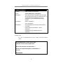
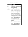
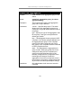
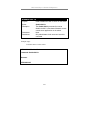
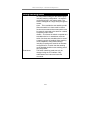
create snmp user
Purpose
Syntax
Description
Parameters
Used to create a new SNMP user and adds the
user to an SNMP group that is also created by this
command.
create snmp user <username 32>
<groupname 32> {encrypted(1)
[by_password(1) auth [md5(2) <auth_password
8-16 > |
sha(3) <auth_password 8-20 >]
priv [none(1) | des(2) <priv_password 8-16>] |
by_key(2) auth [md5(2) <auth_key 32-32>|
sha(3) <auth_key 40-40>] priv [none(1) |
des(2) <priv_key 32-32> ]]}
The create snmp user command creates a new
SNMP user and adds the user to an SNMP group
that is also created by this command.
<username 32> − An alphanumeric name of up to
32 characters that will identify the new SNMP user.
<groupname 32> − An alphanumeric name of up to
32 characters that will identify the SNMP group the
new SNMP user will be associated with.
by_password – Requires the SNMP user to enter a
password for authentication and privacy. The
password is defined by specifying the
auth_password below. This method is
recommended.
by_key - Requires the SNMP user to enter a
encryption key for authentication and privacy. The
key is defined by specifying the priv_password
below. This method is not recommended.
Message integrity − ensures that packets have not
been tampered with during transit.
Authentication − determines if an SNMP message
is from a valid source.
Encryption − scrambles the contents of messages
to prevent it being viewed by an unauthorized
source.
49
DES-3226S Layer 2 Switch CLI Reference
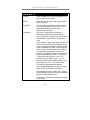
create snmp user
Restrictions
encrypted – Specifies that the password will be in
an encrypted format.
auth [md5|sha] – Initiate an authentication-level
setting session.
md5 − Specifies that the HMAC-MD5-96
authentication level will be used.
sha − Specifies that the HMAC-SHA-96
authentication level will be used.
<auth_password 8-20> − An alphanumeric sting of
between 8 and 20 characters that will be used to
authorize the agent to receive packets for the host.
des <priv_password 8-16> − An alphanumeric
string of between 8 and 16 characters that will be
used to encrypt the contents of messages the host
sends to the agent.
Only administrator-level users can issue this
command.
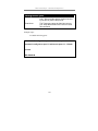
Example usage:
To create an SNMP user on the switch:
DES-3226S:4#create snmp user dlink default encrypted
by_password auth md5 auth_password priv none
Command: create snmp user dlink default encrypted
by_password auth md5 auth_password priv none
Success.
DES-3226S:4#
50
DES-3226S Layer 2 Switch CLI Reference
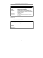
delete snmp user
Purpose
Used to remove an SNMP user from an SNMP
group and also to delete the associated SNMP
group.
Syntax
delete snmp user <username 32>
Description
The delete snmp user command removes an
SNMP user from its SNMP group and then
deletes the associated SNMP group.
Parameters
<username 32> − An alphanumeric string of up
to 32 characters that identifies the SNMP user
that will be deleted.
Restrictions
Only administrator-level users can issue this
command.
Example usage:
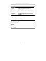
To delete a previously entered SNMP user on the switch:
DES-3226S:4#delete snmp user dlink
Command: delete snmp user dlink
Success.
DES-3226S:4#
51
DES-3226S Layer 2 Switch CLI Reference
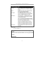
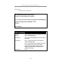
show snmp user
Purpose
Used to display information about each SNMP
username in the SNMP group username table.
Syntax
show snmp user
Description
The show snmp user command displays
information about each SNMP username in the
SNMP group username table.
Parameters
None.
Restrictions
Only administrator-level users can issue this
command.
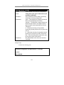
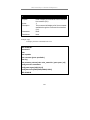
Example usage:
To display the SNMP users currently configured on the switch:
DES-3226S:4#show snmp user
Command: show snmp user
Username
PrivProtocol
Group Name
SNMP Version Auth-Protocol
--------------- --------------- ------------ ------------- -----------initial
initial
V3
None
Total Entries: 1
DES-3226S:4#
52
None
DES-3226S Layer 2 Switch CLI Reference
create snmp view
Purpose
Syntax
Description
Parameters
Restrictions
Used to assign views to community strings to
limit which MIB objects and SNMP manager can
access.
create snmp view <view_name 32> <oid>
view_type [included|excluded]
The create snmp view command assigns
views to community strings to limit which MIB
objects an SNMP manager can access.
<view_name 32> − An alphanumeric string of
up to 32 characters that identifies the SNMP
view that will be created.
<oid> − The object ID that identifies an object
tree (MIB tree) that will be included or excluded
from access by an SNMP manager.
included − Include this object in the list of
objects that an SNMP manager can access.
excluded − Exclude this object from the list of
objects that an SNMP manager can access.
Only administrator-level users can issue this
command.
Example usage:
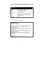
To create an SNMP view:
DES-3226S:4#create snmp view dlinkview 1.3.6 view_type
included
Command: create snmp view dlinkview 1.3.6 view_type included
Success.
DES-3226S:4#
53
DES-3226S Layer 2 Switch CLI Reference
delete snmp view
Purpose
Used to remove an SNMP view entry previously
created on the switch.
Syntax
delete snmp view <view_name 32>
[all|<oid>]
Description
The delete snmp view command is used to
remove an SNMP view previously created on
the switch.
Parameters
<view_name 32> − An alphanumeric string of
up to 32 characters that identifies the SNMP
view to be deleted.
all − Specifies that all of the SNMP views on the
switch will be deleted.
<oid> − The object ID that identifies an object
tree (MIB tree) that will be deleted from the
switch.
Restrictions
Only administrator-level users can issue this
command.
Example usage:
To delete a previously configured SNMP view from the switch:
DES-3226S:4#delete snmp view dlinkview all
Command: delete snmp view dlinkview all
Success.
DES-3226S:4#
54
DES-3226S Layer 2 Switch CLI Reference
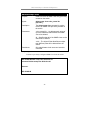
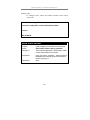
show snmp view
Purpose
Used to display an SNMP view previously
created on the switch.
Syntax
show snmp view {<view_name 32>}
Description
The show snmp view command displays an
SNMP view previously created on the switch.
Parameters
<view_name 32> − An alphanumeric string of
up to 32 characters that identifies the SNMP
view that will be displayed.
Restrictions
None.
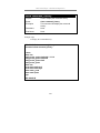
Example usage:
To display SNMP view configuration:
DES-3226S:4#show snmp view
Command: show snmp view
Vacm View Table Settings
View Name
Subtree
-------------------------------------------ReadView
1
WriteView
1
NotifyView
1.3.6
restricted
1.3.6.1.2.1.1
restricted
1.3.6.1.2.1.11
restricted
1.3.6.1.6.3.10.2.1
restricted
1.3.6.1.6.3.11.2.1
restricted
1.3.6.1.6.3.15.1.1
CommunityView
1
CommunityView
1.3.6.1.6.3
CommunityView
.3.6.1.6.3.1
Total Entries: 11
DES-3226S:4#
55
View Type
---------Included
Included
Included
Included
Included
Included
Included
Included
Included
Excluded
Included
DES-3226S Layer 2 Switch CLI Reference
create snmp community
Purpose
Used to create an SNMP community string to
define the relationship between the SNMP
manager and an agent. The community string
acts like a password to permit access to the
agent on the switch. One or more of the
following characteristics can be associated with
the community string:
An Access List of IP addresses of SNMP
managers that are permitted to use the
community string to gain access to the switch’s
SNMP agent.
An MIB view that defines the subset of all MIB
objects that will be accessible to the SNMP
community.
Read|write or read-only level permission for the
MIB objects accessible to the SNMP
community.
Syntax
create snmp community <community_string
32> view <view_name 32>
[read_only|read_write]
Description
The create snmp community command is
used to create an SNMP community string and
to assign access-limiting characteristics to this
community string.
Parameters
<community_string 32> − An alphanumeric
string of up to 32 characters that is used to
identify members of an SNMP community. This
string is used like a password to give remote
SNMP managers access to MIB objects in the
switch’s SNMP agent.
<view_name 32> − An alphanumeric string of
up to 32 characters that is used to identify the
group of MIB objects that a remote SNMP
manager is allowed to access on the switch.
56
DES-3226S Layer 2 Switch CLI Reference
read_only − Specifies that SNMP community
members using the community string created
with this command can only read the contents of
the MIBs on the switch.
read_write − Specifies that SNMP community
members using the community string created
with this command can read from and write to
the contents of the MIBs on the switch.
Restrictions
Only administrator-level users can issue this
command.
Example usage:
To create the SNMP community string “dlink:”
DES-3226S:4#create snmp community dlink view ReadView
read_write
Command: create snmp community dlink view ReadView
read_write
Success.
57
DES-3226S Layer 2 Switch CLI Reference
delete snmp community
Purpose
Used to remove a specific SNMP community
string from the switch.
Syntax
delete snmp community <community_string
32>
Description
The delete snmp community command is
used to remove a previously defined SNMP
community string from the switch.
Parameters
<community_string 32> − An alphanumeric
string of up to 32 characters that is used to
identify members of an SNMP community. This
string is used like a password to give remote
SNMP managers access to MIB objects in the
switch’s SNMP agent.
Restrictions
Only administrator-level users can issue this
command.
Example usage:
To delete the SNMP community string “dlink:”
DES-3226S:4#delete snmp community dlink
Command: delete snmp community dlink
Success.
DES-3226S:4#
58
DES-3226S Layer 2 Switch CLI Reference
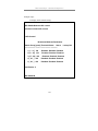
show snmp community
Purpose
Used to display SNMP community strings
configured on the switch.
Syntax
show snmp community {<community_string
32>}
Description
The show snmp community command is used
to display SNMP community strings that are
configured on the switch.
Parameters
<community_string 32> − An alphanumeric
string of up to 32 characters that is used to
identify members of an SNMP community. This
string is used like a password to give remote
SNMP managers access to MIB objects in the
switch’s SNMP agent.
Restrictions
None.
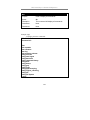
Example usage:
To display the currently entered SNMP community strings:
DES-3226S:4#show snmp community
Command: show snmp community
SNMP Community Table
Community Name
View Name
Access Right
-------------------------------- -------------------------------- -----------dlink
ReadView
read_write
private
CommunityView
read_write
public
CommunityView
read_only
Total Entries: 3
59
DES-3226S Layer 2 Switch CLI Reference
config snmp engineID
Purpose
Used to configure a name for the SNMP engine
on the switch.
Syntax
config snmp engineID <snmp_engineID>
Description
The config snmp engineID command
configures a name for the SNMP engine on the
switch.
Parameters
<snmp_engineID> − An alphanumeric string
that will be used to identify the SNMP engine on
the switch.
Restrictions
Only administrator-level users can issue this
command.
Example usage:
To give the SNMP agent on the switch the name “0035636666”
DES-3226S:4#config snmp 0035636666
Command: config snmp engineID 0035636666
Success.
DES-3226S:4#
60
DES-3226S Layer 2 Switch CLI Reference
show snmp engineID
Purpose
Used to display the identification of the SNMP
engine on the switch.
Syntax
show snmp engineID
Description
The show snmp engineID command displays
the identification of the SNMP engine on the
switch.
Parameters
None.
Restrictions
None.
Example usage:
To display the current name of the SNMP engine on the switch:
DES-3226S:4#show snmp engineID
Command: show snmp engineID
SNMP Engine ID : 0035636666
DES-3226S:4#
61
DES-3226S Layer 2 Switch CLI Reference
create snmp group
Purpose
Used to create a new SNMP group, or a table
that maps SNMP users to SNMP views.
Syntax
create snmp group <groupname 32>
[v1|v2c|v3
[noauth_nopriv|auth_nopriv|auth_priv]]
{read_view <view_name 32>|write_view
<view_name 32>|notify_view <view_name
32>}
Description
The create snmp group command creates a
new SNMP group, or a table that maps SNMP
users to SNMP views.
Parameters
<groupname 32> − An alphanumeric name of
up to 32 characters that will identify the SNMP
group the new SNMP user will be associated
with.
v1 – Specifies that SNMP version 1 will be used.
The Simple Network Management Protocol
(SNMP), version 1, is a network management
protocol that provides a means to monitor and
control network devices.
v2c – Specifies that SNMP version 2c will be
used. The SNMP v2c supports both
centralized and distributed network
management strategies. It includes
improvements in the Structure of Management
Information (SMI) and adds some security
features.
v3 – Specifies that the SNMP version 3 will be
used. SNMP v3 provides secure access to
devices through a combination of authentication
and encrypting packets over the network.
SNMP v3 adds:
Message integrity − ensures that packets have
not been tampered with during transit.
62
DES-3226S Layer 2 Switch CLI Reference
create snmp group
Authentication − determines if an SNMP
message is from a valid source.
Encryption − scrambles the contents of
messages to prevent it being viewed by an
unauthorized source.
noauth_nopriv − Specifies that there will be no
authorization and no encryption of packets sent
between the switch and a remote SNMP
manager.
auth_nopriv − Specifies that authorization will be
required, but there will be no encryption of
packets sent between the switch and a remote
SNMP manager.
auth_priv − Specifies that authorization will be
required, and that packets sent between the
switch and a remote SNMP manger will be
encrypted.
read_view – Specifies that the SNMP group
being created can request SNMP messages.
write_view – Specifies that the SNMP group
being created has write privileges.
<view_name 32> − An alphanumeric string of
up to 32 characters that is used to identify the
group of MIB objects that a remote SNMP
manager is allowed to access on the switch.
notify_view − Specifies that the SNMP group
being created can receive SNMP trap
messages generated by the switch’s SNMP
agent.
Restrictions
Only administrator-level users can issue this
command.
63
DES-3226S Layer 2 Switch CLI Reference
Example usage:
To create an SNMP group named “sg1:”
DES-3226S:4#create snmp group sg1 v3 noauth_nopriv read_view
v1 write_view v1 notify_view v1
Command: create snmp group sg1 v3 noauth_nopriv read_view v1
write_view v1 notify_view v1
Success.
DES-3226S:4#
64
DES-3226S Layer 2 Switch CLI Reference
delete snmp group
Purpose
Used to remove an SNMP group from the
switch.
Syntax
delete snmp group <groupname 32>
Description
The delete snmp group command is used to
remove an SNMP group from the switch.
Parameters
<groupname 32> − An alphanumeric name of
up to 32 characters that will identify the SNMP
group the new SNMP user will be associated
with.
Restrictions
Only administrator-level users can issue this
command.
Example usage:
To delete the SNMP group named “sg1”.
DES-3226S:4#delete snmp group sg1
Command: delete snmp group sg1
Success.
DES-3226S:4#
65
DES-3226S Layer 2 Switch CLI Reference
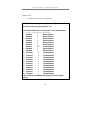
show snmp groups
Purpose
Used to display the group-names of SNMP
groups currently configured on the switch. The
security model, level, and status of each group
are also displayed.
Syntax
show snmp groups
Description
The show snmp groups command displays the
group-names of SNMP groups currently
configured on the switch. The security model,
level, and status of each group are also
displayed.
Parameters
None.
Restrictions
None.
Example usage:
To display the currently configured SNMP groups on the switch:
DES-3226S:4#show snmp groups
Command: show snmp groups
Vacm Access Table Settings
Group Name
ReadView Name
WriteView Name
Notify View Name
Security Model
Security Level
: Group3
: ReadView
: WriteView
: NotifyView
: SNMPv3
: NoAuthNoPriv
Group Name
ReadView Name
WriteView Name
Notify View Name
Security Model
: Group4
: ReadView
: WriteView
: NotifyView
: SNMPv3
66
DES-3226S Layer 2 Switch CLI Reference
Security Level
: authNoPriv
Group Name
ReadView Name
WriteView Name
Notify View Name
Security Model
Security Level
: Group5
: ReadView
: WriteView
: NotifyView
: SNMPv3
: authNoPriv
Group Name
ReadView Name
WriteView Name
Notify View Name
Security Model
Security Level
: Group6
: ReadView
: WriteView
: NotifyView
: SNMPv3
: authPriv
Group Name
ReadView Name
WriteView Name
Notify View Name
Security Model
Security Level
: Group7
: ReadView
: WriteView
: NotifyView
: SNMPv3
: authPriv
Group Name
ReadView Name
WriteView Name
Notify View Name
Security Model
Security Level
: initial
: restricted
:
: restricted
: SNMPv3
: NoAuthNoPriv
Group Name
ReadView Name
WriteView Name
Notify View Name
Security Model
Security Level
: ReadGroup
: CommunityView
:
: CommunityView
: SNMPv1
: NoAuthNoPriv
67
DES-3226S Layer 2 Switch CLI Reference
Group Name
ReadView Name
WriteView Name
Notify View Name
Security Model
Security Level
: ReadGroup
: CommunityView
:
: CommunityView
: SNMPv2
: NoAuthNoPriv
Group Name
ReadView Name
WriteView Name
Notify View Name
Security Model
Security Level
: WriteGroup
: CommunityView
: CommunityView
: CommunityView
: SNMPv1
: NoAuthNoPriv
Group Name
ReadView Name
WriteView Name
Notify View Name
Security Model
Security Level
: WriteGroup
: CommunityView
: CommunityView
: CommunityView
: SNMPv2
: NoAuthNoPriv
Total Entries: 10
DES-3226S:4#
68
DES-3226S Layer 2 Switch CLI Reference
create snmp host
Purpose
Used to create a recipient of SNMP traps
generated by the switch’s SNMP agent.
Syntax
create snmp host <ipaddr> [v1|v2c|v3
[noauth_nopriv|auth_nopriv|auth_priv]
<auth_string 32>]
Description
The create snmp host command creates a
recipient of SNMP traps generated by the
switch’s SNMP agent.
Parameters
<ipaddr> − The IP address of the remote
management station that will serve as the
SNMP host for the switch.
v1 – Specifies that SNMP version 1 will be used.
The Simple Network Management Protocol
(SNMP), version 1, is a network management
protocol that provides a means to monitor and
control network devices.
v2c – Specifies that SNMP version 2c will be
used. The SNMP v2c supports both
centralized and distributed network
management strategies. It includes
improvements in the Structure of Management
Information (SMI) and adds some security
features.
v3 – Specifies that the SNMP version 3 will be
used. SNMP v3 provides secure access to
devices through a combination of authentication
and encrypting packets over the network.
SNMP v3 adds:
Message integrity − ensures that packets have
not been tampered with during transit.
Authentication − determines if an SNMP
message is from a valid source.
69
DES-3226S Layer 2 Switch CLI Reference
create snmp host
Encryption − scrambles the contents of
messages to prevent it being viewed by an
unauthorized source.
noauth_nopriv − Specifies that there will be no
authorization and no encryption of packets sent
between the switch and a remote SNMP
manager.
auth_nopriv − Specifies that authorization will be
required, but there will be no encryption of
packets sent between the switch and a remote
SNMP manager.
auth_priv − Specifies that authorization will be
required, and that packets sent between the
switch and a remote SNMP manger will be
encrypted.
<auth_sting 32> − An alphanumeric string used
to authorize a remote SNMP manager to access
the switch’s SNMP agent.
Restrictions
Only administrator-level users can issue this
command.
Example usage:
To create an SNMP host to receive SNMP messages:
70
DES-3226S Layer 2 Switch CLI Reference
DES-3226S:4#create snmp host 10.48.74.100 v3 auth_priv public
Command: create snmp host 10.48.74.100 v3 auth_priv public
Success.
DES-3226S:4#
delete snmp host
Purpose
Used to remove a recipient of SNMP traps
generated by the switch’s SNMP agent.
Syntax
delete snmp host <ipaddr>
Description
The delete snmp host command deletes a
recipient of SNMP traps generated by the
switch’s SNMP agent.
Parameters
<ipaddr> − The IP address of a remote SNMP
manager that will receive SNMP traps
generated by the switch’s SNMP agent.
Restrictions
Only administrator-level users can issue this
command.
Example usage:
To delete an SNMP host entry:
71
DES-3226S Layer 2 Switch CLI Reference
DES-3226S:4#delete snmp host 10.48.74.100
Command: delete snmp host 10.48.74.100
Success.
DES-3226S:4#
show snmp host
Purpose
Used to display the recipient of SNMP traps
generated by the switch’s SNMP agent.
Syntax
show snmp host {<ipaddr>}
Description
The show snmp host command is used to
display the IP addresses and configuration
information of remote SNMP managers that are
designated as recipients of SNMP traps that are
generated by the switch’s SNMP agent.
Parameters
<ipaddr> − The IP address of a remote SNMP
manager that will receive SNMP traps
generated by the switch’s SNMP agent.
Restrictions
None.
Example usage:
To display the currently configured SNMP hosts on the switch:
72
DES-3226S Layer 2 Switch CLI Reference
DES-3226S:4#show snmp host
Command: show snmp host
SNMP Host Table
Host IP Address SNMP Version
---------------
Community Name
--------------------- ------------------------------
10.48.76.23
V2c private
10.48.74.100
V3
authpriv
Total Entries: 2
73
public
DES-3226S Layer 2 Switch CLI Reference
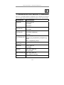
8
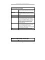
MAC N OTIFICATION C OMMANDS
Command
Parameters
config
mac_notification
ports <portlist>|all
interval <int 1-2147483647>
historysize <int 1 - 500>
enable
mac_notification
disable
mac_notification
show
mac_notification
{ports}
74
DES-3226S Layer 2 Switch CLI Reference
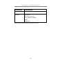
config mac_notification
Purpose
Used to configure MAC address notification.
Syntax
config mac_notification
ports <portlist>|all
interval <sec>
historysize <1 - 500>
Description
MAC address notification is used to monitor
MAC addresses learned and entered into the
FDB.
Parameters
ports <portlist> - specifies a range of ports to
be configured. The port list is specified by
listing the lowest switch number and the
beginning port number on that switch, separated
by a colon. Then the highest switch number,
and the highest port number of the range (also
separated by a colon) are specified. The
beginning and end of the port list range are
seperated by a dash. For example, 1:3
specifies switch number 1, port 3. 2:4 specifies
switch number 2, port 4. 1:3-2:4 specifies all of
the ports between switch 1, port 3 and switch 2,
port 4 − in numerical order.
all – to configure all ports for MAC
notification.
interval <sec> - time in seconds between
notifications.
historysize <1 - 500> - maximum number of
entries listed in the history log used for
notification.
Restrictions
Only administrator-level users can issue this
command.
75
DES-3226S Layer 2 Switch CLI Reference
Example usage:
To enable MAC address notification for unit 1 ports 6-9:
DES-3226S:4#config mac_notification ports 1:6-1:9 enabled
Command: config mac_notification ports 1:6-1:9 enabled
Success.
DES-3226S:4#
76
DES-3226S Layer 2 Switch CLI Reference
config mac_notification
Purpose
Used to configure MAC address notification.
Syntax
config mac_notification
ports <portlist>/all
interval <sec>
historysize <1 - 500>
Description
MAC address notification is used to monitor
MAC addresses learned and entered into the
FDB.
Parameters
ports <portlist> - specifies a range of ports to
be configured. The port list is specified by
listing the lowest switch number and the
beginning port number on that switch, separated
by a colon. Then the highest switch number,
and the highest port number of the range (also
separated by a colon) are specified. The
beginning and end of the port list range are
seperated by a dash. For example, 1:3
specifies switch number 1, port 3. 2:4 specifies
switch number 2, port 4. 1:3-2:4 specifies all of
the ports between switch 1, port 3 and switch 2,
port 4 − in numerical order.
all – to configure all ports for MAC notification.
interval <sec 1-2147483647> - time in seconds
between notifications.
historysize <1 - 500> - maximum number of
entries listed in the history log used for
notification.
Restrictions
Only administrator-level users can issue this
command.
77
DES-3226S Layer 2 Switch CLI Reference
Example usage:
To configure a 60 second interval for MAC address notification on
unit 1 ports 6-9:
DES-3226S:4#config mac_notification ports 1:6-1:9 60
Command: config mac_notification ports 1:6-1:9 interval 60
Success.
DES-3226S:4#
enable mac_notification
Purpose
Used to globally enable MAC address
notification without changing the
mac_notification configuration.
Syntax
enable mac_notification
Description
Enables MAC notification on the switch.
Parameters
None.
Restrictions
Only administrator-level users can issue this
command.
Example usage:
To globally enable MAC notification:
DES-3226S:4#enable mac_notification
Command: enable mac_notification
Success.
DES-3226S:4#
78
DES-3226S Layer 2 Switch CLI Reference
disable mac_notification
Purpose
Used to disable MAC address notification
globally without changing mac_notification
configuration..
Syntax
disable mac_notification
Description
Disables MAC notification on the switch.
Parameters
None.
Restrictions
Only administrator-level users can issue this
command.
Example usage:
To globally disable MAC notification:
DES-3226S:4#disable mac_notification
Command: disable mac_notification
Success.
DES-3226S:4#
79
DES-3226S Layer 2 Switch CLI Reference
show mac_notification
Purpose
Used to display MAC address notification.
Syntax
show mac_notification {ports}
Description
Displays MAC notification settings either per
port or globally as desired.
Parameters
none – this will display global MAC notification
settings currently configured including Interval,
History Size and State.
ports – this displays per ports MAC notification
settings.
Restrictions
Only administrator-level users can issue this
command.
Example usage:
To display global MAC notification settings:
DES-3226S:4#show mac_notification
Command: show mac_notification
Global Mac Notification Settings
State
: Disabled
Interval
:1
History Size : 1
DES-3226S:4#
80
DES-3226S Layer 2 Switch CLI Reference
Example usage:
To display per port MAC notification settings:
DES-3226S:4#show mac_notification ports
Command: show mac_notification ports
Port # MAC Address Table Notification State
------ ---------------------------------1
Enabled
2
Enabled
3
Enabled
4
Enabled
5
Enabled
6
Enabled
7
Enabled
8
Enabled
9
Enabled
10
Enabled
11
Enabled
12
Enabled
13
Enabled
14
Enabled
15
Enabled
16
Enabled
17
Enabled
18
Enabled
19
Enabled
20
Enabled
CTRL+C ESC q Quit SPACE n Next Page p Previous Page r
Refresh
81
DES-3226S Layer 2 Switch CLI Reference
9
D OWNLOAD /U PLOAD C OMMANDS
The download|upload commands in the Command Line Interface (CLI) are
listed (along with the appropriate parameters) in the following table.
Command
Parameters
download
firmware <ipaddr>
<path_filename>
unit [all|<unitid>]
configuration <ipaddr>
<path_filename>
{increment}
upload
configuration
log
<ipaddr>
<path_filename>
Each command is listed, in detail, in the following sections.
82
DES-3226S Layer 2 Switch CLI Reference
download
Purpose
Used to download and install new firmware or a
switch configuration file from a TFTP server.
Syntax
download [ firmware <ipaddr>
<path_filename> {unit
[all|<unitid>]}|configuration <ipaddr>
<path_filename> {increment}]
Description
This command is used to download a new
firmware or a switch configuration file from a
TFTP server.
Parameters
firmware − Download and install new firmware
on the switch from a TFTP server.
configuration − Download a switch configuration
file from a TFTP server.
<ipaddr> − The IP address of the TFTP server.
<path_filename> − The DOS path and filename
of the firmware or switch configuration file on
the TFTP server. For example, C:\3226S.had.
unit [all|<unitid>] − all specifies all units
(switches), <unitid> is the unit id of the switch
that will receive the download.
increment − Allows the download of a partial
switch configuration file. This allows a file to be
downloaded that will change only the switch
parameters explicitly stated in the configuration
file. All other switch parameters will remain
unchanged.
Restrictions
The TFTP server must be on the same IP
subnet as the switch. Only administrator-level
users can issue this command.
83
DES-3226S Layer 2 Switch CLI Reference
Example usage:
To download a configuration file:
DES-3226S:4#download configuration 10.48.74.121
c:\cfg\setting.txt
Command: download configuration 10.48.74.121 c:\cfg\setting.txt
Connecting to server................... Done.
Download configuration............. Done.
DES-3226S:4#
84
DES-3226S Layer 2 Switch CLI Reference
upload
Purpose
Used to upload the current switch settings or the
switch history log to a TFTP server.
Syntax
upload [configuration|log] <ipaddr>
<path_filename>
Description
This command is used to upload either the
switch’s current settings or the switch’s history
log to a TFTP server.
Parameters
configuration − Specifies that the switch’s
current settings will be uploaded to the TFTP
server.
log − Specifies that the switch history log will be
uploaded to the TFTP server.
<ipaddr> − The IP address of the TFTP server.
The TFTP server must be on the same IP
subnet as the switch.
<path_filename> − Specifies the location of the
switch configuration file on the TFTP server.
This file will be replaced by the uploaded file
from the switch.
Restrictions
The TFTP server must be on the same IP
subnet as the switch. Only administrator-level
users can issue this command.
Example usage:
To upload a configuration file:
DES-3226S:4#upload configuration 10.48.74.121 c:\cfg\log.txt
Command: upload configuration 10.48.74.121 c:\cfg\log.txt
Connecting to server................... Done.
Upload configuration...................Done.
DES-3226S:4#
85
DES-3226S Layer 2 Switch CLI Reference
10
N ETWORK M ONITORING C OMMANDS
The network monitoring commands in the Command Line Interface (CLI) are
listed (along with the appropriate parameters) in the following table.
Command
Parameters
show packet ports
<portlist>
show error ports
<portlist>
show utilitzation
clear counters
ports <portlist>
clear log
show log
index <value>
enable syslog
disable syslog
show syslog
create syslog host
all
<index 1-4>
severity
informational
warning
all
facility
local0
local1
local2
local3
86
DES-3226S Layer 2 Switch CLI Reference
Command
Parameters
local4
local5
local6
local7
udp_port <int>
ipaddress <ipaddr>
state [enabled|disabled]
config syslog host
delete syslog host
show syslog host
all
<index 1-4>
severity
informational
warning
all
facility
local0
local1
local2
local3
local4
local5
local6
local7
udp_port <int>
ipaddress <ipaddr>
state [enabled|disabled]
<index 1-4>
all
<index 1-4>
Each command is listed, in detail, in the following sections.
87
DES-3226S Layer 2 Switch CLI Reference
show packet ports
Purpose
Used to display statistics about the packets sent
and received by the switch.
Syntax
show packet ports <portlist>
Description
This command is used to display statistics about
packets sent and received by ports specified in
the port list.
Parameters
<portlist> − specifies a range of ports to be
displayed. The port list is specified by listing the
lowest switch number and the beginning port
number on that switch, separated by a colon.
Then the highest switch number, and the
highest port number of the range (also
separeted by a colon) are specified. The
beginning and end of the port list range are
seperated by a dash. For example, 1:3
specifies switch number 1, port 3. 2:4 specifies
switch number 2, port 4. 1:3-2:4 specifies all of
the ports between switch 1, port 3 and switch 2,
port 4 − in numerical order.
Restrictions
None.
88
DES-3226S Layer 2 Switch CLI Reference
Example usage:
To display the packets analysis for port 7 of module 2:
DES-3226S:4#show packet port 2:7
Port number : 2:7
Frame Size
Total|sec
------------
Frame Counts Frames|sec
------------
64
----------
Frame Type
----------
3275
10
RX Bytes
65-127
755
10
128-255
316
1
256-511
145
512-1023
1024-1518
-------
Total
---------
408973
1657
RX Frames
4395
19
0
TX Bytes
7918
178
15
0
TX Frames
111
2
0
0
Unicast RX
152
1
Multicast RX
557
2
Broadcast RX 3686
16
Broadcast RX 4495
42
DES-3226S:4#
89
DES-3226S Layer 2 Switch CLI Reference
show error ports
Purpose
Used to display the error statistics for a range of
ports.
Syntax
show error ports <portlist>
Description
This command will display all of the packet error
statistics collected and logged by the switch for
a given port list.
Parameters
<portlist> − Specifies a range of ports to be
displayed. The port list is specified by listing the
lowest switch number and the beginning port
number on that switch, separated by a colon.
Then the highest switch number, and the
highest port number of the range (also
separated by a colon) are specified. The
beginning and end of the port list range are
separated by a dash. For example, 1:3 specifies
switch number 1, port 3. 2:4 specifies switch
number 2, port 4. 1:3-2:4 specifies all of the
ports between switch 1, port 3 and switch 2, port
4 − in numerical order.
Restrictions
None.
90
DES-3226S Layer 2 Switch CLI Reference
Example usage:
To display the errors of the port 3 of module 1:
DES-3226S:4#show errors port 1:3
RX Frames
TX Frames
---------------
----------------
CRC Error
0
Excessive Deferral
0
Undersize
0
CRC Error
0
Oversize
0
Late Collision
0
Fragment
0
Excessive Collision
0
Jabber
0
Drop Pkts
Single Collision
0
Collision
0
0
show utilization
Purpose
Used to display real-time port utilization
statistics.
Syntax
show utilization
Description
This command will display the real-time port
utilization statistics for the switch.
Parameters
None.
Restrictions
None.
91
DES-3226S Layer 2 Switch CLI Reference
Example usage:
To display the port utilization statistics:
DES-3226S:4#show utilization
Port TX|sec RX|sec Util
---- ---------- ---------- ---1:1
0
0
0
1:2
0
0
0
1:3
0
0
0
1:4
0
0
0
1:5
0
0
0
1:6
0
0
0
1:7
0
0
0
1:8
0
0
0
1:9
0
0
0
1:10
0
0
0
1:11
0
0
0
1:12
0
0
0
1:13
0
0
0
1:14
0
0
0
1:15
0
0
0
1:16
0
0
0
1:17
0
0
0
1:18
0
0
0
1:19
0
0
0
1:20
0
0
0
1:21
0
0
0
Port TX|sec RX|sec Util
------------- ---------- ---1:22
0
0
0
1:23
0
0
0
1:24
0
0
0
1:25
0
0
0
1:26
19
49
1
2:1
0
0
0
2:2
0
0
0
2:3
0
0
0
2:4
0
0
0
2:5
0
0
0
2:6
0
0
0
2:7
0
30
1
2:8
0
0
0
2:9
30
0
1
2:10
0
0
0
2:11
0
0
0
2:12
0
0
0
2:13
0
0
0
2:14
0
0
0
2:15
0
0
0
2:16
0
0
0
92
DES-3226S Layer 2 Switch CLI Reference
clear counters
Purpose
Used to clear the switch’s statistics counters.
Syntax
clear counters {ports <portlist>}
Description
This command will clear the counters used by
the switch to compile statistics.
Parameters
<portlist> − Specifies a range of ports to be
configured. The port list is specified by listing
the lowest switch number and the beginning
port number on that switch, separated by a
colon. Then the highest switch number, and the
highest port number of the range (also
separated by a colon) are specified. The
beginning and end of the port list range are
separated by a dash. For example, 1:3 specifies
switch number 1, port 3. 2:4 specifies switch
number 2, port 4. 1:3-2:4 specifies all of the
ports between switch 1, port 3 and switch 2, port
4 − in numerical order.
Restrictions
Only administrator-level users can issue this
command.
Example usage:
To clear the counters:
DES-3226S:4#clear counters ports 2:7-2:9
Command: clear counters ports 2:7-2:9
Success.
93
DES-3226S Layer 2 Switch CLI Reference
clear log
Purpose
Used to clear the switch’s history log.
Syntax
clear log
Description
This command will clear the switch’s history log.
Parameters
None.
Restrictions
Only administrator-level users can issue this
command.
Example usage:
To clear the log information:
DES-3226S:4#clear log
Command: clear log
Success.
DES-3226S:4#
94
DES-3226S Layer 2 Switch CLI Reference
show log
Purpose
Used to display the switch history log.
Syntax
show log {index <value>}
Description
This command will display the contents of the
switch’s history log.
Parameters
index <value> − The show log command will
display the history log until the log number
reaches this value.
Restrictions
None.
Example usage:
To display the switch history log:
DES-3226S:4#show log
Index Time
Log Text
----- ----------
---------------------------------------------------------------
4 000d00h50m Unit 1, Successful login through Console
(Username: Anonymous)
3 000d00h50m Unit 1, Logout through Console (Username:
Anonymous)
2 000d00h49m Unit 1, Successful login through Console
(Username: Anonymous)
000d00h49m Unit 1, Logout through Console (Username:
Anonymous)
DES-3226S:4#
95
DES-3226S Layer 2 Switch CLI Reference
enable syslog
Purpose
Used to enable the system log to be sent to a
remote host.
Syntax
enable syslog
Description
The enable syslog command enables the
system log to be sent to a remote host.
Parameters
None.
Restrictions
Only administrator-level users can issue this
command.
Example usage:
To the syslog function on the switch:
DES-3226S:4#enable syslog
Command: enable syslog
Success.
DES-3226S:4#
96
DES-3226S Layer 2 Switch CLI Reference
disable syslog
Purpose
Used to enable the system log to be sent to a
remote host.
Syntax
disable syslog
Description
The disable syslog command enables the
system log to be sent to a remote host.
Parameters
None.
Restrictions
Only administrator-level users can issue this
command.
Example usage:
To disable the syslog function on the switch:
DES-3226S:4#disable syslog
Command: disable syslog
Success.
DES-3226S:4#
97
DES-3226S Layer 2 Switch CLI Reference
show syslog
Purpose
Used to display the syslog protocol status as
enabled or disabled.
Syntax
show syslog
Description
The show syslog command displays the syslog
status as enabled or disabled.
Parameters
None.
Restrictions
None.
Example usage:
To display the current status of the syslog function:
DES-3226S:4#show syslog
Command: show syslog
Syslog Global State: Enabled
DES-3226S:4#
98
DES-3226S Layer 2 Switch CLI Reference
create syslog host
Purpose
Used to create a new syslog host.
Syntax
config syslog host [all|<index 1-4>] {severity
[informational|warning|all]|
facility[local0|local1|local2|local3|
local4|local5|local6|local7]|udp_port<int>|
ipaddress <ipaddr>| state[enabled|disabled]
Description
The create syslog host command is used to
create a new syslog host.
Parameters
all − Specifies that the command will be applied
to all hosts.
<index 1-4> − Specifies that the command will
be applied to an index of hosts. There are four
available indexes, numbered 1 through 4.
severity − Severity level indicator. These are
described in the following:
Bold font indicates that the corresponding
severity level is currently supported on the
switch.
Numerical
Severity
Code
0
Emergency: system is unusable
1
Alert: action must be taken immediately
2
Critical: critical conditions
3
Error: error conditions
4
Warning: warning conditions
5
Notice: normal but significant condition
6
Informational: informational messages
7
Debug: debug-level messages
99
DES-3226S Layer 2 Switch CLI Reference
create syslog host
informational − Specifies that informational
messages will be sent to the remote host. This
corresponds to number 6 from the list above.
warning − Specifies that warning messages will
be sent to the remote host. This corresponds to
number 4 from the list above.
all − Specifies that all of the currently supported
syslog messages that are generated by the
switch will be sent to the remote host.
facility − Some of the operating system
daemons and processes have been assigned
Facility values. Processes and daemons that
have not been explicitly assigned a Facility may
use any of the"local use" facilities or they may
use the "user-level" Facility. Those Facilities that
have been designated are shown in the
following: Bold font indicates the facility values
that the switch currently supports.
Numerical
Facility
Code
0
kernel messages
1
user-level messages
2
mail system
3
system daemons
4
security|authorization messages
5
syslog
messages generated internally by
6
line printer subsystem
7
network news subsystem
8
UUCP subsystem
9
clock daemon
100
DES-3226S Layer 2 Switch CLI Reference
create syslog host
10
security|authorization messages
11
FTP daemon
12
NTP subsystem
13
log audit
14
log alert
15
clock daemon
16
local use 0 (local0)
17
local use 1 (local1)
18
local use 2 (local2)
19
local use 3 (local3)
20
local use 4 (local4)
21
local use 5 (local5)
22
local use 6 (local6)
23
local use 7 (local7)
local0 − Specifies that local use 0 messages will
be sent to the remote host. This corresponds to
number 16 from the list above.
local1 − Specifies that local use 1 messages will
be sent to the remote host. This corresponds to
number 17 from the list above.
local2 − Specifies that local use 2 messages will
be sent to the remote host. This corresponds to
number 18 from the list above.
local3 − Specifies that local use 3 messages will
be sent to the remote host. This corresponds to
number 19 from the list above.
local4 − Specifies that local use 4 messages will
be sent to the remote host. This corresponds to
number 20 from the list above.
101
DES-3226S Layer 2 Switch CLI Reference
create syslog host
local5 − Specifies that local use 5 messages will
be sent to the remote host. This corresponds to
number 21 from the list above.
local6 − Specifies that local use 6 messages will
be sent to the remote host. This corresponds to
number 22 from the list above.
local7 − Specifies that local use 7 messages will
be sent to the remote host. This corresponds to
number 23 from the list above.
udp_port <int> − Specifies the UDP port number
that the syslog protocol will use to send
messages to the remote host.
ipaddress <ipaddr> − Specifies the IP address
of the remote host where syslog messages will
be sent.
state [enabled|disabled] − Allows the sending of
syslog messages to the remote host, specified
above, to be enabled and disabled.
Restrictions
Only administrator-level users can issue this
command.
Example usage:
To create syslog host:
DES-3226S:4#create syslog host 1 severity all facility local0
Command: create syslog host 1 severity all facility local0
Success.
DES-3226S:4#
102
DES-3226S Layer 2 Switch CLI Reference
config syslog host
Purpose
Used to configure the syslog protocol to send
system log data to a remote host.
Syntax
config syslog host [all|<index 1-4>] {severity
[informational|warning|all]|
facility[local0|local1|local2|local3|
local4|local5|local6|local7]|udp_port<int>|
ipaddress <ipaddr>| state[enabled|disabled]
Description
The config syslog host command is used to
configure the syslog protocol to send system log
information to a remote host.
Parameters
all − Specifies that the command will be applied
to all hosts.
<index 1-4> − Specifies that the command will
be applied to an index of hosts. There are four
available indexes, numbered 1 through 4.
severity − Severity level indicator. These are
described in the following:
Bold font indicates that the corresponding
severity level is currently supported on the
switch.
Numerical
Severity
Code
0
Emergency: system is unusable
1
Alert: action must be taken immediately
2
Critical: critical conditions
3
Error: error conditions
4
Warning: warning conditions
5
Notice: normal but significant condition
6
Informational: informational messages
7
Debug: debug-level messages
informational − Specifies that informational
103
DES-3226S Layer 2 Switch CLI Reference
messages will be sent to the remote host. This
corresponds to number 6 from the list above.
warning − Specifies that warning messages will
be sent to the remote host. This corresponds to
number 4 from the list above.
all − Specifies that all of the currently supported
syslog messages that are generated by the
switch will be sent to the remote host.
facility − Some of the operating system
daemons and processes have been assigned
Facility values. Processes and daemons that
have not been explicitly assigned a Facility may
use any of the"local use" facilities or they may
use the "user-level" Facility. Those Facilities that
have been designated are shown in the
following: Bold font indicates that the facility
values the switch currently supports.
Numerical
Facility
Code
0
kernel messages
1
user-level messages
2
mail system
3
system daemons
4
security|authorization messages
5
messages generated internally by
syslog
6
line printer subsystem
7
network news subsystem
8
UUCP subsystem
9
clock daemon
10
security|authorization messages
11
FTP daemon
104
DES-3226S Layer 2 Switch CLI Reference
12
NTP subsystem
13
log audit
14
log alert
15
clock daemon
16
local use 0 (local0)
17
local use 1 (local1)
18
local use 2 (local2)
19
local use 3 (local3)
20
local use 4 (local4)
21
local use 5 (local5)
22
local use 6 (local6)
23
local use 7 (local7)
local0 − Specifies that local use 0 messages will
be sent to the remote host. This corresponds to
number 16 from the list above.
local1 − Specifies that local use 1 messages will
be sent to the remote host. This corresponds to
number 17 from the list above.
local2 − Specifies that local use 2 messages will
be sent to the remote host. This corresponds to
number 18 from the list above.
local3 − Specifies that local use 3 messages will
be sent to the remote host. This corresponds to
number 19 from the list above.
local4 − Specifies that local use 4 messages will
be sent to the remote host. This corresponds to
number 20 from the list above.
local5 − Specifies that local use 5 messages will
be sent to the remote host. This corresponds to
number 21 from the list above.
105
DES-3226S Layer 2 Switch CLI Reference
local6 − Specifies that local use 6 messages will
be sent to the remote host. This corresponds to
number 22 from the list above.
local7 − Specifies that local use 7 messages will
be sent to the remote host. This corresponds to
number 23 from the list above.
udp_port <int> − Specifies the UDP port number
that the syslog protocol will use to send
messages to the remote host.
ipaddress <ipaddr> − Specifies the IP address
of the remote host where syslog messages will
be sent.
state [enabled|disabled] − Allows the sending of
syslog messages to the remote host, specified
above, to be enabled and disabled.
Restrictions
Only administrator-level users can issue this
command.
Example usage:
To configure a syslog host:
DES-3226S:4#config syslog host all severity all facility local0
Command: config syslog host all severity all facility local0
Success.
DES-3226S:4#
106
DES-3226S Layer 2 Switch CLI Reference
delete syslog host
Purpose
Used to remove a syslog host, that has been
previously configured, from the switch.
Syntax
delete syslog host [<index 1-4>|all]
Description
The delete syslog host command is used to
remove a syslog host that has been previously
configured from the switch.
Parameters
<index 1-4> − Specifies that the command will
be applied to an index of hosts. There are four
available indexes, numbered 1 through 4.
all − Specifies that the command will be applied
to all hosts.
Restrictions
Only administrator-level users can issue this
command.
Example usage:
To delete a previously configured syslog host:
DES-3226S:4#delete syslog host 4
Command: delete syslog host 4
Success.
DES-3226S:4#
107
DES-3226S Layer 2 Switch CLI Reference
show syslog host
Purpose
Used to display the syslog hosts currently
configured on the switch.
Syntax
show syslog host {<index 1-4>}
Description
The show syslog host command is used to
display the syslog hosts that are currently
configured on the switch.
Parameters
<index 1-4> − Specifies that the command will
be applied to an index of hosts. There are four
available indexes, numbered 1 through 4.
Restrictions
None.
Example usage:
To show Syslog host information:
DES-3226S:4#show syslog host
Command: show syslog host
Syslog Global State: Disabled
Host Id Host IP Address Severity Facility UDP port Status
-------
---------------
-------------- -------- --------
--------
1
10.1.1.2
All
Local0
514
Disabled
2
10.40.2.3
All
Local0
514
Disabled
3
10.21.13.1
All
Local0
514
Disabled
Total Entries : 3
DES-3226S:4#
108
DES-3226S Layer 2 Switch CLI Reference
11
S PANNING T REE C OMMANDS
The switch supports 802.1d STP and 802.1w Rapid STP. The spanning tree
commands in the Command Line Interface (CLI) are listed (along with the
appropriate parameters) in the following table.
Command
Parameters
config stp
maxage <value>
hellotime <value>
forwarddelay <value>
priority <value>
fdpdu [enable|disable]
txholdcount <1-10>
version [rstp|stp]
config stp ports
<portlist>
cost <value>
priority <value>
migrate [yes|no]
edge [true|false]
p2p [true|false|auto]
state [enable|disable]
enable stp
disable stp
show stp
show stp ports
<portlist>
Each command is listed, in detail, in the following sections.
109
DES-3226S Layer 2 Switch CLI Reference
config stp
Purpose
Used to setup STP and RSTP on the switch.
Syntax
config stp {maxage <value>|hellotime
<value>|forwarddelay <value>|priority
<value>|fbpdu [enabled|disabled]|
txholdcount <1-10>| version[rstp|stp]}
Description
This command is used to setup the Spanning
Tree Protocol (STP) for the entire switch.
Parameters
maxage <value> − The maximum amount of
time (in seconds) that the switch will wait to
receive a BPDU packet before reconfiguring
STP. The default is 20 seconds.
hellotime <value> − The time interval between
transmission of configuration messages by the
root device. The default is 2 seconds.
forwarddelay <value> − The maximum amount
of time (in seconds) that the root device will wait
before changing states. The default is 15
seconds.
priority <value> − A numerical value between 0
and 61440 that is used in determining the root
device, root port, and designated port. The
device with the highest priority becomes the root
device. The lower the numerical value, the
higher the priority. The default is 32,768.
fbpdu [enabled|disabled] − Allows the
forwarding of STP BPDU packets from other
network devices when STP is disabled on the
switch. The default is enabled.
txholdcount <1-10> - the maximum number of
Hello packets transmitted per interval. Default
value = 3.
version [rstp|stp] - select the Spanning Tree
Protocol version used for the switch. For IEEE
110
DES-3226S Layer 2 Switch CLI Reference
config stp
802.1d STP select stp. Select rstp for IEEE
802.1w Rapid STP.
Restrictions
Only administrator-level users can issue this
command.
Example usage:
To configure STP with maxage 18 and hellotime 4:
DES-3226S:4#config stp maxage 18 hellotime 4
Command: config stp maxage 18 hellotime 4
Success.
DES-3226S:4#
111
DES-3226S Layer 2 Switch CLI Reference
config stp ports
Purpose
Used to setup STP on the port level.
Syntax
config stp ports <portlist> {cost
<value>|priority <value>| migrate [yes|no]|
edge [true|false]| p2p [true|false]| state
[enabled|disabled]
Description
This command is used to create and configure
STP for a group of ports.
Parameters
cost <value> − This defines a metric that
indicates the relative cost of forwarding packets
to the specified port list. Port cost can be set
from 1 to 200000000. The lower the number,
the greater the probability the port will be
chosen to forward packets.
Default port cost: 100Mbps port = 200000
Gigabit port = 20000
priority <value> − Port Priority can be from 0 to
240. The lower the number, the greater the
probability the port will be chosen as the Root
Port. Default = 128.
<portlist> − Specifies a range of ports to be
configured. The port list is specified by listing
the lowest switch number and the beginning
port number on that switch, separated by a
colon. Then the highest switch number, and the
highest port number of the range (also
separated by a colon) are specified. The
beginning and end of the port list range are
separated by a dash. For example, 1:3 specifies
switch number 1, port 3. 2:4 specifies switch
number 2, port 4. 1:3-2:4 specifies all of the
ports between switch 1, port 3 and switch 2, port
4 − in numerical order.
migrate [yes|no] – yes will enable the port to
migrate from 802.1d STP status to 802.1w
112
DES-3226S Layer 2 Switch CLI Reference
config stp ports
RSTP status. RSTP can coexist with standard
STP, however the benefits of RSTP are not
realized on a port where an 802.1d network
connects to an 802.1w enabled network.
Migration should be enabled (yes) on ports
connected to network stations or segments that
will be upgraded to 802.1w RSTP onall or some
portion of the segment.
edge [true|false] – true designates the port as
an edge port. Edge ports cannot create loops,
however an edge port can lose edge port status
if a topology change creates a potential for a
loop. An edge port normally should not receive
BPDU packets. If a BPDU packet is received it
automatically loses edge port status. False
indicates that the port does not have edge port
status.
p2p [true|false|auto] – true indicates a point-topoint (P2P) shared link. P2P ports are similar to
edge ports however they are restricted in that a
P2P port must operate in full-duplex. Like edge
ports, P2P ports transition to a forwarding state
rapidly thus benefiting from RSTP. A p2p value
of false indicates that the port cannot have p2p
status. Auto allows the port to have p2p status
whenever possible and operate as if the p2p
status were true. If the port cannot maintain this
status (for example if the port is forced to halfduplex operation) the p2p status changes to
operate as if the p2p value were false.
state [enabled|disabled] − Allows STP to be
enabled or disabled for the ports specified in the
port list. The default is disabled.
Restrictions
Only administrator-level users can issue this
command.
113
DES-3226S Layer 2 Switch CLI Reference
Example usage:
To configure STP with path cost 19, priority 15, and state enabled for
ports 1-5 of module 1.
DES-3226S:4#config stp ports 1:1-1:5 cost 19 priority 15 state
enabled
Command: config stp ports 1-5 cost 19 priority 15 state enabled
Success.
DES-3226S:4#
enable stp
Purpose
Used to globally enable STP on the switch.
Syntax
enable stp
Description
This command allows the Spanning Tree
Protocol to be globally enabled on the switch.
Parameters
None.
Restrictions
Only administrator-level users can issue this
command.
114
DES-3226S Layer 2 Switch CLI Reference
Example usage:
To enable STP, globally, on the switch:
DES-3226S:4#enable stp
Command: enable stp
Success.
DES-3226S:4#
disable stp
Purpose
Used to globally disable STP on the switch.
Syntax
disable stp
Description
This command allows the Spanning Tree
Protocol to be globally disabled on the switch.
Parameters
None.
Restrictions
Only administrator-level users can issue this
command.
115
DES-3226S Layer 2 Switch CLI Reference
Example usage:
To disable STP on the switch:
DES-3226S:4#disable stp
Command: disable stp
Success.
DES-3226S:4#
show stp
Purpose
Used to display the switch’s current STP
configuration.
Syntax
show stp
Description
This command displays the switch’s current
STP configuration.
Parameters
none
Restrictions
None.
Example usage:
116
DES-3226S Layer 2 Switch CLI Reference
To display the status of STP on the switch:
Status 1: STP enabled with STP compatible version
DES-3226S:4#show stp
Command: show stp
Bridge Parameters Settings
STP Status
: Enabled
Max Age
: 20
Hello Time
:2
Forward Delay : 15
Priority
: 32768
STP Version : STP compatible
TX Hold Count : 3
Forwarding BPDU : Enabled
Bridge Current Status
Designated Root Bridge : 00-00-51-43-70-00
Root Priority
: 32768
Cost to Root
: 200000
Root Port
: 10
Last Topology Change : 53sec
Topology Changes Count : 1
Protocol Specification : 3
Max Age
: 20
Hello Time
:2
Forward Delay
: 15
Hold Time
:3
CTRL+C ESC q Quit SPACE n Next Page p Previous Page r Refresh
DES-3226S:4#
117
DES-3226S Layer 2 Switch CLI Reference
Status 2 : STP disabled
DES-3226S:4#show stp
Command: show stp
Bridge Parameters Settings
STP Status
: Disabled
Max Age
: 20
Hello Time
:2
Forward Delay : 15
Priority
: 32768
STP Version
: STP compatible
TX Hold Count : 3
Forwarding BPDU : Enabled
DES-3226S:4#
118
DES-3226S Layer 2 Switch CLI Reference
show stp ports
Purpose
Used to display the switch’s current per-port
group STP configuration.
Syntax
show stp ports <portlist>
Description
This command displays the switch’s current perport group STP configuration.
Parameters
<portlist> − Specifies a range of ports to be
configured. The port list is specified by listing
the lowest switch number and the beginning
port number on that switch, separated by a
colon. Then the highest switch number, and the
highest port number of the range (also
separated by a colon) are specified. The
beginning and end of the port list range are
seperated by a dash. For example, 1:3 specifies
switch number 1, port 3. 2:4 specifies switch
number 2, port 4. 1:3-2:4 specifies all of the
ports between switch 1, port 3 and switch 2, port
4 − in numerical order.
Restrictions
None
119
DES-3226S Layer 2 Switch CLI Reference
Example usage:
To display STP state of port 1-9 of module 1:
DES-3226S:4#show stp ports
Command: show ports
Port Designated Bridge State Cost
------ ------------------
-----
Pri Edge P2P Status
---------- ---- ----
--- ----------
Role
----------
1
N/A
Yes *200000
128 No Yes Disabled Disabled
2
N/A
Yes *200000
128 No Yes Disabled Disabled
3
N/A
Yes *200000
128 No Yes Disabled Disabled
4
N/A
Yes *200000
128 No Yes Disabled Disabled
5
N/A
Yes *200000
128 No Yes Disabled Disabled
6
N/A
Yes *200000
128 No Yes Disabled Disabled
7
N/A
Yes *200000
128 No Yes Disabled Disabled
8
N/A
Yes *200000
128 No Yes Disabled Disabled
9
N/A
Yes *200000
128 No Yes Disabled Disabled
10
N/A
Yes *200000
128 No Yes Forwarding NonStp
11
N/A
Yes *200000
128 No Yes Disabled Disabled
12
N/A
Yes *200000
128 No Yes Disabled Disabled
13
N/A
Yes *200000
128 No Yes Disabled Disabled
14
N/A
Yes *200000
128 No Yes Disabled Disabled
15
N/A
Yes *200000
128 No Yes Disabled Disabled
16
N/A
Yes *200000
128 No Yes Disabled Disabled
17
N/A
Yes *200000
128 No Yes Disabled Disabled
18
N/A
Yes *200000
128 No Yes Disabled Disabled
19
N/A
Yes *200000
128 No Yes Disabled Disabled
20
N/A
Yes *200000
128 No Yes Disabled Disabled
21
N/A
Yes *200000
128 No Yes Disabled Disabled
CTRL+C ESC q Quit SPACE n Next Page p Previous Page r Refresh
DES-3226S:4#
120
DES-3226S Layer 2 Switch CLI Reference
12
F ORWARDING D ATABASE C OMMANDS
The layer 2 forwarding database commands in the Command Line Interface
(CLI) are listed (along with the appropriate parameters) in the following table.
Command
Parameters
create fdb
<vlan_name 32>
<macaddr>
port <port>
create
multicast_fdb
<vlan_name 32>
config
multicast_fdb
<vlan_name 32>
<macaddr>
<macaddr> [add|delete]
<portlist>
config multicast
port_filtering_mod
e
[<portlist>|all]
[forward_all_groups|forward_unregistered_gr
oups|
filter_unregistered_groups]
config fdb
aging_time
<sec 10-1000000>
delete fdb
<vlan_name 32>
<macaddr>
clear fdb
vlan <vlan_name 32>
port <port>|all
show multicast_fdb
vlan <vlan_name 32>
mac_address <macaddr>
show multicast
{<portlist>}
121
DES-3226S Layer 2 Switch CLI Reference
Command
Parameters
port_filtering_mod
e
show fdb
port <port>
vlan <vlan_name 32>
mac_address <macaddr>
static
aging_time
Each command is listed, in detail, in the following sections.
122
DES-3226S Layer 2 Switch CLI Reference
create fdb
Purpose
Used to create a static entry to the unicast MAC
address forwarding table (database)
Syntax
create fdb <vlan_name 32> <macaddr> [port
<port>]
Description
This command will make an entry into the
switch’s unicast MAC address forwarding
database.
Parameters
<vlan_name 32> − The name of the VLAN on
which the MAC address resides.
<macaddr> − The MAC address that will be
added to the forwarding table.
<port> − The port number corresponding to the
MAC destination address. The switch will
always forward traffic to the specified device
through this port.
Restrictions
Only administrator-level users can issue this
command.
Example usage:
To create a unicast MAC FDB entry:
DES-3226S:4#create fdb default 00-00-00-00-01-02 port 2:5
Command: create fdb default 00-00-00-00-01-02 port 2:5
Success.
DES-3226S:4#
123
DES-3226S Layer 2 Switch CLI Reference
create multicast_fdb
Purpose
Used to create a static entry to the multicast
MAC address forwarding table (database)
Syntax
create multicast_fdb <vlan_name 32>
<macaddr>
Description
This command will make an entry into the
switch’s multicast MAC address forwarding
database.
Parameters
<vlan_name 32> − The name of the VLAN on
which the MAC address resides.
<macaddr> − The MAC address that will be
added to the forwarding table.
Restrictions
Only administrator-level users can issue this
command.
Example usage:
To create multicast MAC forwarding:
DES-3226S:4#create multicast_fdb default 01-00-5E-00-00-00
Command: create multicast_fdb default 01-00-5E-00-00-00
Success.
DES-3226S:4#
124
DES-3226S Layer 2 Switch CLI Reference
config multicast_fdb
Purpose
Used to configure the switch’s multicast MAC
address forwarding database.
Syntax
config multicast_fdb <vlan_name 32>
<macaddr> [add|delete] <portlist>
Description
This command configures the multicast MAC
address forwarding table.
Parameters
<vlan_name 32> − The name of the VLAN on
which the MAC address resides.
<macaddr> − The MAC address that will be
added to the forwarding table.
[add|delete] − Add will add the MAC address to
the forwarding table. Delete will remove the
MAC address from the forwarding table.
<portlist> − Specifies a range of ports to be
configured. The port list is specified by listing
the lowest switch number and the beginning
port number on that switch, separated by a
colon. Then the highest switch number, and the
highest port number of the range (also
separated by a colon) are specified. The
beginning and end of the port list range are
separated by a dash. For example, 1:3 specifies
switch number 1, port 3. 2:4 specifies switch
number 2, port 4. 1:3-2:4 specifies all of the
ports between switch 1, port 3 and switch 2, port
4 − in numerical order.
Restrictions
Only administrator-level users can issue this
command.
125
DES-3226S Layer 2 Switch CLI Reference
Example usage:
To add multicast MAC forwarding:
DES-3226S:4#config multicast_fdb default 01-00-5E-00-00-00 add
1:1-1:5
Command: config multicast_fdb default 01-00-5E-00-00-00 add
1:1-1:5
Success.
DES-3226S:4#
126
DES-3226S Layer 2 Switch CLI Reference
config multicast port_filtering_mode
Purpose
Used to configure the multicast port filtering.
Syntax
config multicast port_filtering_mode [<portlist>|all]
[forward_all_groups|forward_unregistered_groups
| filter_unregistered_groups]
Description
This command configures the multicast filtering
and forwarding for specified ports.
Parameters
<portlist> − Specifies a range of ports to be
configured. The port list is specified by listing the
lowest switch number and the beginning port
number on that switch, separated by a colon.
Then the highest switch number, and the highest
port number of the range (also separated by a
colon) are specified. The beginning and end of the
port list range are separated by a dash. For
example, 1:3 specifies switch number 1, port 3.
2:4 specifies switch number 2, port 4. 1:3-2:4
specifies all of the ports between switch 1, port 3
and switch 2, port 4 − in numerical order.
forward_all_groups – The groups of ports
specified in the <portlist> are instructed to forward
all multicast packets, i.e. no filtering takes places
since multicast packets from unregistered and
registered multicast groups are forwarded in the
specified port group.
forward_unregistered_groups - The groups of
ports specified in the <portlist> are instructed to
forward only multicast packets from unregistered
multicast groups. Multicast packets from
registered groups are dropped.
filter_unregistered_groups - The groups of ports
specified in the <portlist> are instructed to filter all
multicast packets from unregistered multicast
groups. Multicast packets from registered groups
are forwarded.
127
DES-3226S Layer 2 Switch CLI Reference
config multicast port_filtering_mode
Restrictions
Only administrator-level users can issue this
command.
Example usage:
To configure the multicast packet filtering mode for ports:
DES-3226S:4#config multicast port_filtering_mode 1:1-1:4
forward_all_groups
Command: config multicast port_filtering_mode 1:1-1:4
forward_all_groups
Success.
DES-3226S:4#
128
DES-3226S Layer 2 Switch CLI Reference
config fdb aging_time
Purpose
Used to set the aging time of the forwarding
database.
Syntax
config fdb aging_time <sec>
Description
The aging time affects the learning process of
the switch. Dynamic forwarding table entries,
which are made up of the source MAC
addresses and their associated port numbers,
are deleted from the table if they are not
accessed within the aging time. The aging time
can be from 10 to 1000000 seconds with a
default value of 300 seconds. A very long aging
time can result in dynamic forwarding table
entries that are out-of-date or no longer exist.
This may cause incorrect packet forwarding
decisions by the switch. If the aging time is too
short however, many entries may be aged out
too soon. This will result in a high percentage of
received packets whose source addresses
cannot be found in the forwarding table, in
which case the switch will broadcast the packet
to all ports, negating many of the benefits of
having a switch.
Parameters
<sec> − The aging time for the MAC address
forwarding database value.
Restrictions
Only administrator-level users can issue this
command.
129
DES-3226S Layer 2 Switch CLI Reference
Example usage:
To set the fdb aging time:
DES-3226S:4#config fdb aging_time 300
Command: config fdb aging_time 300
Success.
DES-3226S:4#
130
DES-3226S Layer 2 Switch CLI Reference
delete fdb
Purpose
Used to delete an entry to the switch’s
forwarding database.
Syntax
delete fdb <vlan_name 32> <macaddr>
Description
This command is used to delete a previous
entry to the switch’s MAC address forwarding
database.
Parameters
<vlan_name 32> − The name of the VLAN on
which the MAC address resides.
<macaddr> − The MAC address that will be
added to the forwarding table.
Restrictions
Only administrator-level users can issue this
command.
Example usage:
To delete a permanent FDB entry:
DES-3226S:4#delete fdb default 00-00-00-00-01-02
Command: delete fdb default 00-00-00-00-01-02
Success.
DES-3226S:4#
131
DES-3226S Layer 2 Switch CLI Reference
clear fdb
Purpose
Used to clear the switch’s forwarding database
of all dynamically learned MAC addresses.
Syntax
clear fdb [vlan <vlan_name 32>|port
<port>|all]
Description
This command is used to clear dynamically
learned entries to the switch’s forwarding
database.
Parameters
<vlan_name 32> − The name of the VLAN on
which the MAC address resides.
<port> − The port number corresponding to the
MAC destination address. The switch will
always forward traffic to the specified device
through this port.
all − Clears all dynamic entries to the switch’s
forwarding database.
Restrictions
Only administrator-level users can issue this
command.
Example usage:
To clear all FDB dynamic entries:
DES-3226S:4#clear fdb all
Command: clear fdb all
Success.
DES-3226S:4#
132
DES-3226S Layer 2 Switch CLI Reference
show multicast_fdb
Purpose
Used to display the contents of the switch’s
multicast forwarding database.
Syntax
show mulitcast_fdb [vlan <vlan_name
32>|mac_address <macaddr>
Description
This command is used to display the current
contents of the switch’s multicast MAC address
forwarding database.
Parameters
<vlan_name 32> − The name of the VLAN on
which the MAC address resides.
<macaddr> − The MAC address that will be
added to the forwarding table.
Restrictions
None.
Example usage:
To display multicast MAC address table:
DES-3226S:4#show multicast_fdb
Command: show multicast_fdb
VLAN Name
: default
MAC Address
: 01-00-5E-00-00-00
Egress Ports
: 1:1-1:5,1:26,2:26
Mode
: Static
Total Entries
:1
133
DES-3226S Layer 2 Switch CLI Reference
show multicast_port_filtering_mode
Purpose
Used to display the current multicast port
filtering mode.
Syntax
show multicast port_filtering_mode {<portlist>}
Description
This command is used to display the current
multicast port filtering settings.
Parameters
<portlist> − Specifies a range of ports to be
displayed. The port list is specified by listing the
lowest switch number and the beginning port
number on that switch, separated by a colon.
Then the highest switch number, and the
highest port number of the range (also
separated by a colon) are specified. The
beginning and end of the port list range are
separated by a dash. For example, 1:3 specifies
switch number 1, port 3. 2:4 specifies switch
number 2, port 4. 1:3-2:4 specifies all of the
ports between switch 1, port 3 and switch 2, port
4 − in numerical order.
If no ports are specified, the multicast port
filtering mode is listed for all ports.
Restrictions
Only administrator-level users can issue this
command.
134
DES-3226S Layer 2 Switch CLI Reference
Example usage:
To show multicast port_filtering_mode for ports:
DES-3226S:4#show multicast port_filtering_mode 1:1-1:12
Command: show multicast port_filtering_mode 1:1-1:12
Port
Multicast Filter Mode
------ --------------------------1:1
forward_all_groups
1:2
forward_all_groups
1:3
forward_all_groups
1:4
forward_all_groups
1:5
forward_unregistered_groups
1:6
forward_unregistered_groups
1:7
forward_unregistered_groups
1:8
forward_unregistered_groups
1:9
forward_unregistered_groups
1:10
forward_unregistered_groups
1:11
filter_unregistered_groups
1:12
filter_unregistered_groups
DES-3226S:4#
135
DES-3226S Layer 2 Switch CLI Reference
show fdb
Purpose
Used to display the current unicast MAC
address forwarding database.
Syntax
show fdb {port <port>|vlan <vlan_name
32>|mac_address
<macaddr>|static|aging_time}
Description
This command will display the current contents
of the switch’s forwarding database.
Parameters
<port> − The port number corresponding to the
MAC destination address. The switch will
always forward traffic to the specified device
through this port.
<vlan_name 32> − The name of the VLAN on
which the MAC address resides.
<macaddr> − The MAC address that will be
added to the forwarding table.
static − Displays the static MAC address entries.
aging_time − Displays the aging time for the
MAC address forwarding database.
Restrictions
None.
136
DES-3226S Layer 2 Switch CLI Reference
Example usage:
To display unicast MAC address table:
DES-3226S:4#show fdb
Command: show fdb
Unicast MAC Address Ageing Time = 300
VID VLAN Name
MAC Address
Port Type
---- ---------------- ----------------- ------ ---------------1 default
00-00-39-34-66-9A 10
Dynamic
1 default
00-00-51-43-70-00 10
Dynamic
1 default
00-00-5E-00-01-01 10
Dynamic
1 default
00-00-74-60-72-2D 10
Dynamic
1 default
00-00-81-05-00-80 10
Dynamic
1 default
00-00-81-05-02-00 10
Dynamic
1 default
00-00-81-48-70-01 10
Dynamic
1 default
00-00-E2-4F-57-03 10
Dynamic
1 default
00-00-E2-61-53-18 10
Dynamic
1 default
00-00-E2-6B-BC-F6 10
Dynamic
1 default
00-00-E2-7F-6B-53 10
Dynamic
1 default
00-00-E2-82-7D-90 10
Dynamic
1 default
00-00-F8-7C-1C-29 10
Dynamic
1 default
00-01-02-03-04-00 CPU Self
1 default
00-01-02-03-04-05 10
Dynamic
1 default
00-01-30-10-2C-C7 10
Dynamic
1 default
00-01-30-FA-5F-00 10
Dynamic
1 default
00-02-3F-63-DD-68 10
Dynamic
CTRL+C ESC q Quit SPACE n Next Page ENTER Next Entry a All
137
DES-3226S Layer 2 Switch CLI Reference
13
B ROADCAST S TORM C ONTROL
C OMMANDS
The broadcast storm control commands in the Command Line Interface (CLI)
are listed (along with the appropriate parameters) in the following table.
Command
config traffic control
Parameters
<storm_grouplist>
all
broadcast [enable|disable]
multicast [enable|disable]
dlf [enable|disable]
threshold <value>
show traffic control
group_list <storm_grouplist>
Each command is listed, in detail, in the following sections.
138
DES-3226S Layer 2 Switch CLI Reference
config traffic control
Purpose
Used to configure broadcast|multicast traffic
control.
Syntax
config traffic control [<storm_grouplist>|all]
broadcast [enable|disable]|multicast
[enable|disable]|dlf
[enable|disable]|threshold <value>
Description
This command is used to configure broadcast
storm control.
Parameters
<storm_grouplist> − Used to specify a
broadcast storm control group with the syntax:
module_id:group_id.
all − Specifies all broadcast storm control
groups on the switch.
broadcast [enable|disable] − Enables or
disables broadcast storm control.
multicast [enable|disable] − Enables or disables
multicast storm control.
dlf [enable|disable] − Enables or disables dlf
traffic control.
threshold <value> − The upper threshold at
which the specified traffic control is switched on.
The <value> is the number of
broadcast|multicast|dlf packets, in Kbps,
received by the switch that will trigger the storm
traffic control measures.
Restrictions
Only administrator-level users can issue this
command.
139
DES-3226S Layer 2 Switch CLI Reference
Example usage:
To configure traffic control and enable broadcast storm control
system wide:
DES-3226S:4#config traffic control all broadcast enable
Command: config traffic control all broadcast enable
Success.
DES-3226S:4#
show traffic control
Purpose
Used to display current traffic control settings.
Syntax
show traffic control <storm_grouplist>
Description
This command displays the current storm traffic
control configuration on the switch.
Parameters
group_list <storm_grouplist> − Used to specify a
broadcast storm control group with the syntax:
module_id:group_id.
Restrictions
None.
140
DES-3226S Layer 2 Switch CLI Reference
Example usage:
To display traffic control setting:
DES-3226S:4#show traffic control
Command: show traffic control
Traffic Control
Broadcast Multicast Destination
Module Group [ports] Threshold Storm
Storm
Lookup Fail
------ ------------- --------- --------- --------- ----------1
1 [ 1 - 8 ] 128
Disabled Disabled Disabled
1
2 [ 9 - 16] 128
Disabled Disabled Disabled
1
3 [17 - 24] 128
Disabled Disabled Disabled
1
4 [ 25 ] 128
Disabled Disabled Disabled
1
5 [ 26 ] 128
Disabled Disabled Disabled
Total Entries: 5
DES-3226S:4#
141
DES-3226S Layer 2 Switch CLI Reference
14
QOS C OMMANDS
The DES-3226S switch supports 802.1p priority queuing. The switch has 4
priority queues. These priority queues are numbered from 0 (Class 0) — the
lowest priority queue — to 3 (Class 3) — the highest priority queue. The eight
priority queues specified in IEEE 802.1p (p0 to p7) are mapped to the switch’s
priority queues as follows:
•
p1 and p2 are assigned to the switch’s Class 0 queue.
•
p0 and p3 are assigned to the switch’s Class 1 queue.
•
p4 and p5 are assigned to the switch’s Class 2 queue.
•
p6 and p7 are assigned to the switch’s Class 3 queue.
Priority scheduling is implemented using two types of methods, strict priority
and round-robin priority. If no changes are made to the QoS priority
scheduling settings the method used is strict priority.
For strict priority-based scheduling, packets residing in the higher priority
queues are transmitted first. Only when these queues are empty, are packets of
lower priority allowed to be transmitted. Higher priority packets always
receive preference regardless of the amount of lower priority packets in the
buffer and regardless of the time elapsed since any lower priority packets have
been transmitted. By default the switch is configured to empty the buffer using
strict priority.
NOTICE: The default QoS scheduling arrangement is
a strict priority schedule. To customize scheduling to
set up round-robin queue clearing, the MAX. Latency
and MAX. Packets values need to be changed using
the config scheduling command. See config
scheduling below.
142
DES-3226S Layer 2 Switch CLI Reference
To use implement round-robin (weighted) priority, the switch’s four priority
queues can be configured to reduce the buffer in a round-robin fashion beginning with the highest priority queue, and proceeding to the lowest
priority queue before returning to the highest priority queue.
The weighted-priority based scheduling alleviates the main disadvantage of
strict priority-based scheduling − in that lower priority queues get starved of
bandwidth − by providing a minimum bandwidth to all queues for
transmission. This is accomplished by configuring the maximum number of
packets allowed to be transmitted from a given priority queue and the
maximum amount of time a given priority queue will have to wait before being
allowed to transmit its accumulated packets. This establishes a Class of
Service (CoS) for each of the switch’s four hardware priority queues.
The possible range for maximum packets is: 0 to 255 packets.
The possible range for maximum latency is: 0 to 255 (in increments of 16
microseconds each).
143
DES-3226S Layer 2 Switch CLI Reference
The commands in the Command Line Interface (CLI) are listed (along with the
appropriate parameters) in the following table.
Command
Parameters
config
bandwidth_control
<portlist>
rx_rate
no_limit
<value 1-1000>
tx_rate
no_limit
<value 1-1000>
<portlist>
show
bandwidth_control
config scheduling
show scheduling
config 802.1p
user_priority
show 802.1p
user_priority
config 802.1p
default_priority
show 802.1p
default_priority
<class_id 0-3>
max_packet <value 0-255>
max_latency <value 0-255>
<priority 0-7>
<class_id 0-3>
<portlist>
all
<priority 0-7>
<portlist>
Each command is listed, in detail, in the following sections.
144
DES-3226S Layer 2 Switch CLI Reference
config bandwidth_control
Purpose
Used to configure bandwidth control on a byport basis.
Syntax
config bandwidth_control <portlist> {re_rate
[no_limit|<value 1-1000>]|tx_rate
[no_limit|<value 1-1000>]}
Description
The config bandwidth_control command is
used to configure bandwidth on a by-port basis.
Parameters
<portlist> − Specifies a range of ports to be
configured. The port list is specified by listing
the lowest switch number and the beginning
port number on that switch, separated by a
colon. Then the highest switch number, and the
highest port number of the range (also
separated by a colon) are specified. The
beginning and end of the port list range are
separated by a dash. For example, 1:3 specifies
switch number 1, port 3. 2:4 specifies switch
number 2, port 4. 1:3-2:4 specifies all of the
ports between switch 1, port 3 and switch 2, port
4 − in numerical order.
rx_rate − Specifies that one of the parameters
below (no_limit or <value 1-1000>) will be
applied to the rate at which the above specified
ports will be allowed to receive packets
no_limit − Specifies that there will be no limit on
the rate of packets received by the above
specified ports.
<value 1-1000> − Specifies the packet limit, in
Mbps, that the above ports will be allowed to
receive.
tx_rate − Specifies that one of the parameters
below (no_limit or <value 1-1000>) will be
applied to the rate at which the above specified
ports will be allowed to transmit packets.
145
DES-3226S Layer 2 Switch CLI Reference
config bandwidth_control
no_limit − Specifies that there will be no limit on
the rate of packets received by the above
specified ports.
<value 1-1000> − Specifies the packet limit, in
Mbps, that the above ports will be allowed to
receive. Gigabit ports must be configured to
using a limit value that is a multiple of 8 i.e. for
Gigabit ports <value 8-1000 in increments of 8>.
Restrictions
Only administrator-level users can issue this
command.
Example usage:
To configure bandwidth control:
DES-3226S:4#config bandwidth_control 1-10 tx_rate 10
Command: config bandwidth_control 1-10 tx_rate 10
Success.
DES-3226S:4#
146
DES-3226S Layer 2 Switch CLI Reference
show bandwidth_control
Purpose
Used to display the bandwidth control
configuration on the switch.
Syntax
show bandwidth_control {<portlist>}
Description
The show bandwidth_control command
displays the current bandwidth control
configuration on the switch, on a port-by-port
basis.
Parameters
<portlist> − Specifies a range of ports to be
configured. The port list is specified by listing
the lowest switch number and the beginning
port number on that switch, separated by a
colon. Then the highest switch number, and the
highest port number of the range (also
separated by a colon) are specified. The
beginning and end of the port list range are
separated by a dash. For example, 1:3 specifies
switch number 1, port 3. 2:4 specifies switch
number 2, port 4. 1:3-2:4 specifies all of the
ports between switch 1, port 3 and switch 2, port
4 − in numerical order.
Restrictions
None.
147
DES-3226S Layer 2 Switch CLI Reference
Example usage:
To display bandwidth control settings:
DES-3226S:4#show bandwidth_control 1-10
Command: show bandwidth_control 1-10
Bandwidth Control Table
Port RX Rate (Mbit|sec) TX_RATE (Mbit|sec)
---- ------------------------
----------------------
1
no_limit
10
2
no_limit
10
3
no_limit
10
4
no_limit
10
5
no_limit
10
6
no_limit
10
7
no_limit
10
8
no_limit
10
9
no_limit
10
10
no_limit
10
DES-3226S:4#
148
DES-3226S Layer 2 Switch CLI Reference
config scheduling
Purpose
Used to configure traffic scheduling for each of
the switch’s QoS queues.
Syntax
config scheduling <class_id 0-3>
{max_packet <value 0-255>|max_latency
<value 0-255>}
Description
The switch contains four hardware priority
queues per device. The switch’s default settings
draw down the four hardware queues in order,
from the highest priority (Class 3) to the lowest
priority (Class 0). Starting with the highest
priority queue (Class 3), the highest priority
queue will transmit all of the packets and empty
its buffer before allowing the next lower priority
queue to transmit its packets. The next highest
priority queue will empty before proceeding to
the next queue and so on. Lower priority queues
are allowed to transmit only if the higher priority
queue(s) in the buffer are completely emptied.
Packets in the higher priority queues are always
emptied before any in the lower priority queues
regardless of latency or volume of the lower
priority queues.
The default settings for QoS scheduling employ
this strict priority scheme to empty priority
queues.
The config scheduling command can be used
to specify the round robin rotation by which
these four hardware priority queues are
reduced. To use a round-robin scheme, the
max_packets parameters and/or the
max_latency parameters must be changed from
the default value of 0.
The max_packets parameter allows you to
specify the maximum number of packets a given
priority queue can transmit before allowing the
149
DES-3226S Layer 2 Switch CLI Reference
config scheduling
next lowest priority queue to begin transmitting
its packets. A value between 0 and 255 packets
can be specified. For example, if a value of 5 is
specified, then the highest priority queue (queue
3) will be allowed to transmit 5 packets. Then
the next lower priority queue (queue 2) will be
allowed to transmit 5 packets, and so on, until
all of the queues have transmitted 5 packets.
The process will then repeat.
The max_latency parameter allows you to
specify the maximum amount of time that
packets will be delayed before being
transmitted. For a given priority queue, a value
between 0 and 255 can be specified. This
number is then multiplied by 16 milliseconds to
determine the maximum allowed latency. For
example, if 3 is specified for queue 3, the
maximum latency allowed will be 3 X 16 ms =
48 ms. When queue 3 has been waiting to
transmit packets for longer than 48 ms, the
currently transmitting priority queue is allowed to
finish transmitting its current packet, and then
queue 2 is allowed to begin transmitting its
packets.
Parameters
<class_id> − Specifies which of the four priority
queues the config scheduling command will
be applied to. The four priority queues are
identified by number − from 0 to 3 − with queue
3 being the highest priority.
max_packet <value 0-255> − Specifies the
maximum number of packets the above
specified priority queue will be allowed to
transmit before allowing the next lowest priority
queue to transmit its packets. A value between
0 and 255 packets can be specified. The default
value is 0.
150
DES-3226S Layer 2 Switch CLI Reference
config scheduling
max_latency <value 0-255> − Specifies the
maximum amount of time the above specified
priority queue will have to wait before being
allowed to transmit any packets that have
accumulated in its transmit buffer. A value
between 0 and 255 can be specified. This value
multiplied by 16 ms is the total time the priority
queue will have to wait. The default value is 0.
Restrictions
Only administrator-level users can issue this
command.
NOTICE: The default QoS scheduling arrangement
is a strict priority schedule. To customize
scheduling to set up weighted or round-robin queue
clearing the max_latency and max_packets values
need to be changed.
151
DES-3226S Layer 2 Switch CLI Reference
Example usage:
To configure traffic scheduling:
DES-3226S:4# config scheduling 0 max_packet 100 max_latency
150
Command: config scheduling 0 max_packet 100 max_latency 150
Success.
DES-3226S:4#
show scheduling
Purpose
Used to display the currently configured traffic
scheduling on the switch.
Syntax
show scheduling
Description
The show scheduling command displays the
current configuration for the maximum number
of packets (max_packets) and the maximum
latency (max_latency) values assigned to the
four priority queues on the switch. The switch’s
default max_latency = 0. At this value, it will
empty the four hardware queues in order, from
the highest priority (queue 3) to the lowest
priority (queue 0).
Parameters
None.
Restrictions
None.
152
DES-3226S Layer 2 Switch CLI Reference
Example usage:
To display the current scheduling configuration:
DES-3226S:4# show scheduling
Command: show scheduling
QOS Output Scheduling
MAX. Packets MAX. Latency
------------------- -----------------Class-0
50
1
Class-1
100
1
Class-2
150
1
Class-3
200
1
DES-3226S:4#
153
DES-3226S Layer 2 Switch CLI Reference
config 802.1p user_priority
Purpose
Used to map the 802.1p user priority of an
incoming packet to one of the four hadware
queues available on the switch.
Syntax
config 802.1p user_priority <priority 0-7>
<class_id 0-3>
The config 802.1p user_priority command is
used to configure the way the switch will map an
incoming packet, based on its 802.1p user
priority tag, to one of the four hardware priority
queues available on the switch. The switch’s
default is to map the incoming 802.1p priority
values to the four hardware queues according to
the following chart:
802.1p
Switch Priority Remark
Value
Queue
-------------------------- ----------0
1
1
0
2
0
3
1
4
2
5
2
6
3
7
3
<priority 0-7> − Specifies which of the 8 802.1p
priority values (0 through 7) you want to map to
one of the switch’s hardware priority queues
(<class_id>, 0 through 3).
Description
Parameters
<class_id 0-3> − Specifies which of the switch’s
hardware priority queues the 802.1p priority
value (specified above) will be mapped to.
Restrictions
Only administrator-level users can issue this
command.
154
DES-3226S Layer 2 Switch CLI Reference
Example usage:
To configure 802.1 user priority on the switch:
DES-3226S:4# config 802.1p user_priority 1 3
Command: config 802.1p user_priority 1 3
Success.
DES-3226S:4#
155
DES-3226S Layer 2 Switch CLI Reference
show 802.1p user_priority
Purpose
Used to display the current mapping between
an incoming packet’s 802.1p priority value and
one of the switch’s four hardware priority
queues.
Syntax
show 802.1p user_priority
Description
The show 802.1p user_priority command
displays the current mapping of an incoming
packet’s 802.1p priority value to one of the
switch’s four hardware priority queues.
Parameters
None.
Restrictions
None.
Example usage:
To show 802.1p user priority:
DES-3226S:4# show 802.1p user_priority
Command: show 802.1p user_priority
COS Class of Traffic
Priority-0 -> <Class-1>
Priority-1 -> <Class-0>
Priority-2 -> <Class-0>
Priority-3 -> <Class-1>
Priority-4 -> <Class-2>
Priority-5 -> <Class-2>
Priority-6 -> <Class-3>
Priority-7 -> <Class-3>
DES-3226S:4#
156
DES-3226S Layer 2 Switch CLI Reference
config 802.1p default_priority
Purpose
Used to specify how to map an incoming
packet that has no 802.1p priority tag to one of
the switch’s four hardware priority queues.
Syntax
config 802.1p default_priority [<portlist>|all]
<priority 0-7>
Description
The config 802.1p default_priority command
allows you to specify the 802.1p priority value
an untagged, incoming packet will be assigned
before being forwarded to its destination.
Parameters
<portlist> − Specifies a range of ports to be
configured. The port list is specified by listing
the lowest switch number and the beginning
port number on that switch, separated by a
colon. Then the highest switch number, and
the highest port number of the range (also
separated by a colon) are specified. The
beginning and end of the port list range are
separated by a dash. For example, 1:3
specifies switch number 1, port 3. 2:4 specifies
switch number 2, port 4. 1:3-2:4 specifies all of
the ports between switch 1, port 3 and switch
2, port 4 − in numerical order.
all − Specifies that the config 802.1p
default_priority command will be applied to all
ports on the switch.
<priority 0-7> − Specifies the 802.1p priority
value that an untagged, incoming packet will
be given before being forwarded to its
destination.
Restrictions
Only administrator-level users can issue this
command.
157
DES-3226S Layer 2 Switch CLI Reference
Example usage:
To configure 802.1p default priority on the switch:
DES-3226S:4#config 802.1p default_priority all 5
Command: config 802.1p default_priority all 5
Success.
DES-3226S:4#
show 802.1 default_priority
Purpose
Used to display the currently configured 802.1p
priority value that will be assigned to an
incoming, untagged packet before being
forwarded to its destination.
Syntax
show 802.1p default_priority {<portlist>}
Description
The show 802.1p default_priority command
displays the currently configured 802.1p priority
value that will be assigned to an incoming,
untagged packet before being forwarded to its
destination.
Parameters
<portlist> − Specifies a range of ports to be
configured. The port list is specified by listing
the lowest switch number and the beginning
port number on that switch, separated by a
colon. Then the highest switch number, and the
highest port number of the range (also
separated by a colon) are specified. The
beginning and end of the port list range are
separated by a dash. For example, 1:3 specifies
switch number 1, port 3. 2:4 specifies switch
number 2, port 4. 1:3-2:4 specifies all of the
ports between switch 1, port 3 and switch 2, port
4 − in numerical order.
158
DES-3226S Layer 2 Switch CLI Reference
show 802.1 default_priority
Restrictions
None.
Example usage:
To display the current 802.1p default priority configuration on the switch:
159
DES-3226S Layer 2 Switch CLI Reference
DES-3226S:4# show 802.1p default_priority
Command: show 802.1p default_priority
Port
------1
2
3
4
5
6
7
8
9
10
11
12
13
14
15
16
17
18
19
20
21
22
23
24
25
26
Priority
----------0
0
0
0
0
0
0
0
0
0
0
0
0
0
0
0
0
0
0
0
0
0
0
0
0
0
DES-3226S:4#
160
DES-3226S Layer 2 Switch CLI Reference
15
P ORT M IRRORING C OMMANDS
The port mirroring commands in the Command Line Interface (CLI) are listed
(along with the appropriate parameters) in the following table.
Command
Parameters
config mirror port
<port> [add|delete]
source ports <portlist> [rx|tx|both]
enable mirror
disable mirror
show mirror
Each command is listed, in detail, in the following sections.
161
DES-3226S Layer 2 Switch CLI Reference
config mirror port
Purpose
Used to configure a mirror port − source port
pair on the switch.
Syntax
config mirror port <port> add source ports
<portlist> [rx|tx|both]
Description
This command allows a range of ports to have
all of their traffic also sent to a designated port,
where a network sniffer or other device can
monitor the network traffic. In addition, you can
specify that only traffic received by or sent by
one or both is mirrored to the Target port.
Parameters
<port> − This specifies the Target port (the port
where mirrored packets will be sent).
source ports – The port or ports being mirrored.
This cannot include the Target port.
<portlist> − This specifies a range of ports that
will be mirrored. That is, the range of ports in
which all traffic will be copied and sent to the
Target port. The port list is specified by listing
the lowest switch number and the beginning
port number on that switch, separated by a
colon. Then the highest switch number, and the
highest port number of the range (also
separated by a colon) are specified. The
beginning and end of the port list range are
separated by a dash. For example, 1:3 specifies
switch number 1, port 3. 2:4 specifies switch
number 2, port 4. 1:3-2:4 specifies all of the
ports between switch 1, port 3 and switch 2, port
4 − in numerical order.
rx − Allows the mirroring of only packets
received by (flowing into) the port or ports in the
port list.
tx − Allows the mirroring of only packets sent to
(flowing out of) the port or ports in the port list.
162
DES-3226S Layer 2 Switch CLI Reference
config mirror port
both − Mirrors all the packets received or sent
by the port or ports in the port list.
Restrictions
The Target port cannot be listed as a source
port. Only administrator-level users can issue
this command.
Example usage:
To add the mirroring ports:
DES-3226S:4# config mirror port 1:5 add source ports 1:1-1:5 both
Command: config mirror port 1:5 add source ports 1:1-1:5 both
Success.
DES-3226S:4#
163
DES-3226S Layer 2 Switch CLI Reference
config mirror delete
Purpose
Used to delete a port mirroring configuration|
Syntax
config mirror port <port> delete source port
<portlist> [rx|tx|both]
Description
This command is used to delete a previously
entered port mirroring configuration.
Parameters
<port> −This specifies the Target port (the port
where mirrored packets will be sent).
<portlist> − This specifies a range of ports that
will be mirrored. That is, the range of ports in
which all traffic will be copied and sent to the
Target port.
rx − Allows the mirroring of only packets
received by (flowing into) the port or ports in the
port list.
tx − Allows the mirroring of only packets sent to
(flowing out of) the port or ports in the port list.
both − Mirrors all the packets received or sent
by the port or ports in the port list.
Restrictions
Only administrator-level users can issue this
command.
Example usage:
To delete the mirroring ports:
DES-3226S:4#config mirror port 1:5 delete source port 1:1-1:5 both
Command: config mirror 1:5 delete source 1:1-1:5 both
Success.
DES-3226S:4#
164
DES-3226S Layer 2 Switch CLI Reference
enable mirror
Purpose
Used to enable a previously entered port
mirroring configuration.
Syntax
enable mirror
Description
This command, combined with the disable
mirror command below, allows you to enter a
port mirroring configuration into the switch, and
then turn the port mirroring on and off without
having to modify the port mirroring configuration.
Parameters
None.
Restrictions
None.
Example usage:
To enable mirroring configurations:
DES-3226S:4#enable mirror
Command: enable mirror
Success.
DES-3226S:4#
165
DES-3226S Layer 2 Switch CLI Reference
disable mirror
Purpose
Used to disable a previously entered port
mirroring configuration.
Syntax
disable mirror
Description
This command, combined with the enable
mirror command above, allows you to enter a
port mirroring configuration into the switch, and
then turn the port mirroring on and off without
having to modify the port mirroring configuration.
Parameters
None.
Restrictions
Only administrator-level users can issue this
command.
Example usage:
To disable mirroring configurations:
DES-3226S:4#disable mirror
Command: disable mirror
Success.
DES-3226S:4#
166
DES-3226S Layer 2 Switch CLI Reference
show mirror
Purpose
Used to show the current port mirroring
configuration on the switch.
Syntax
show mirror
Description
This command displays the current port
mirroring configuration on the switch.
Parameters
None
Restrictions
None.
Example usage:
To display mirroring configuration:
DES-3226S:4#show mirror
Command: show mirror
Current Settings
Target Port: 9
Mirrored Port:
RX:
TX: 1:1-1:5
DES-3226S:4#
167
DES-3226S Layer 2 Switch CLI Reference
16
VLAN C OMMANDS
The VLAN commands in the Command Line Interface (CLI) are listed (along
with the appropriate parameters) in the following table.
Command
Parameters
create vlan
<vlan_name 32>
tag <vlanid>
advertisement
delete vlan
<vlan_name 32>
config vlan
<vlan_name 32>
add [tagged|untagged|forbidden]
delete
<portlist>
advertisement [enable|disable]
config vlan
<vlan_name 32>
delete <portlist>
config vlan
<vlan_name 32>
config gvrp
<portlist>
all
state [enable|disable]
ingress_checking [enable|disable]
acceptable_frame [tagged_only|accept_all]
enable gvrp
disable gvrp
show vlan
<vlan_name 32>
show gvrp
<portlist>
Each command is listed, in detail, in the following sections.
168
DES-3226S Layer 2 Switch CLI Reference
create vlan
Purpose
Used to create a VLAN on the switch.
Syntax
create vlan <vlan_name 32> {tag <vlanid 14094>|advertisement}
Description
This command allows you to create a VLAN on
the switch.
Parameters
<vlan_name 32> − The name of the VLAN to be
created.
<vlanid> − The VLAN ID of the VLAN to be
created. Allowed values = 1-4094
advertisement − Specifies that the VLAN is able
to join GVRP. If this parameter is not set, the
VLAN cannot be configured to have forbidden
ports.
Restrictions
Each VLAN name can be up to 32 characters.
If the VLAN is not given a tag, it will be a portbased VLAN. Only administrator-level users
can issue this command.
Example usage:
To create a VLAN v1, tag 2:
DES-3226S:4#create vlan v1 tag 2
Command: create vlan v1 tag 2
Success.
DES-3226S:4#
169
DES-3226S Layer 2 Switch CLI Reference
delete vlan
Purpose
Used to delete a previously configured VLAN on
the switch.
Syntax
delete vlan <vlan_name 32>
Description
This command will delete a previously
configured VLAN on the switch.
Parameters
<vlan_name 32> − The VLAN name of the
VLAN you want to delete.
Restrictions
Only administrator-level users can issue this
command.
Example usage:
To remove a vlan v1:
DES-3226S:4#delete vlan v1
Command: delete vlan v1
Success.
DES-3226S:4#
170
DES-3226S Layer 2 Switch CLI Reference
config vlan
Purpose
Used to add additional ports to a previously
configured VLAN.
Syntax
config vlan <vlan_name 32> { [ add [ tagged |
untagged | forbidden ] | delete ] <portlist> |
advertisement [ enable | disable]}
Description
This command allows you to add ports to the
port list of a previously configured VLAN. You
can specify the additional ports as tagging,
untagging, or forbidden. The default is to assign
the ports as untagging.
Parameters
<vlan_name 32> − The name of the VLAN you
want to add ports to.
add − Specifies all of the ports on the switch.
tagged − Specifies the additional ports as
tagged.
untagged − Specifies the additional ports as
untagged.
forbidden − Specifies the additional ports as
forbidden.
delete − Deletes the above specified VLAN from
the switch.
<portlist> − A range of ports to add to the VLAN.
The port list is specified by listing the lowest
switch number and the beginning port number
on that switch, separated by a colon. Then the
highest switch number, and the highest port
number of the range (also separated by a colon)
are specified. The beginning and end of the port
list range are separated by a dash. For
example, 1:3 specifies switch number 1, port 3.
2:4 specifies switch number 2, port 4. 1:3-2:4
specifies all of the ports between switch 1, port
3 and switch 2, port 4 − in numerical order.
171
DES-3226S Layer 2 Switch CLI Reference
config vlan
advertisement [enable|disable] − Enables or
disables GVRP on the specified VLAN.
Restrictions
Only administrator-level users can issue this
command.
Example usage:
To add 4 through 8 of module 2 as tagged ports to the VLAN v1:
DES-3226S:4#config vlan v1 add tagged 2:4-2:8
Command: config vlan v1 add tagged 2:4-2:8
Success.
DES-3226S:4#
172
DES-3226S Layer 2 Switch CLI Reference
config gvrp
Purpose
Used to configure GVRP on the switch.
Syntax
config gvrp [<portlist> | all] {state [enable |
disable]|ingress_checking [enable |
disable]|acceptable_frame[tagged_only |
admit_all]pvid<vlanid 1-4094> }
Description
This command is used to configure the Group
VLAN Registration Protocol on the switch. You
can configure ingress checking, the sending and
receiving of GVRP information, and the Port
VLAN ID (PVID).
Parameters
<portlist> − A range of ports for which you want
ingress checking. The port list is specified by
listing the lowest switch number and the
beginning port number on that switch, separated
by a colon. Then the highest switch number,
and the highest port number of the range (also
separated by a colon) are specified. The
beginning and end of the port list range are
separated by a dash. For example, 1:3 specifies
switch number 1, port 3. 2:4 specifies switch
number 2, port 4. 1:3-2:4 specifies all of the
ports between switch 1, port 3 and switch 2, port
4 − in numerical order.
all − Specifies all of the ports on the switch.
state [enable|disable] − Enables or disables
GVRP for the ports specified in the port list.
ingress_checking [enable|disable] − Enables or
disables ingress checking for the specified port
list.
acceptable_frame – This allows a definition of
the type of frame accepted. Acceptable frames
can be limited to tagged frames only
(tagged_only) or can accept tagged and
untagged (accept_all).
173
DES-3226S Layer 2 Switch CLI Reference
config gvrp
pvid – Specifies the default VLAN associated
with the port.
Restrictions
Only administrator-level users can issue this
command.
Example usage:
To set the ingress checking status, the sending and receiving GVRP
information :
DES-3226S:4#config gvrp 1:1-1:4 state enable ingress_checking
enable acceptable_frame tagged_only pvid 2
Command: config gvrp 1:1-1:4 state enable ingress_checking
enable acceptable_frame tagged_only pvid 2
Success.
DES-3226S:4#
174
DES-3226S Layer 2 Switch CLI Reference
enable gvrp
Purpose
Used to enable GVRP on the switch.
Syntax
enable gvrp
Description
This command, along with disable gvrp below,
is used to enable and disable GVRP on the
switch, without changing the GVRP
configuration on the switch.
Parameters
None.
Restrictions
Only administrator-level users can issue this
command.
Example usage:
To enable the generic VLAN Registration Protocol (GVRP):
DES-3226S:4#enable gvrp
Command: enable gvrp
Success.
DES-3226S:4#
175
DES-3226S Layer 2 Switch CLI Reference
disable gvrp
Purpose
Used to disable GVRP on the switch.
Syntax
disable gvrp
Description
This command, along with disable gvrp below,
is used to enable and disable GVRP on the
switch, without changing the GVRP
configuration on the switch.
Parameters
None.
Restrictions
Only administrator-level users can issue this
command.
Example usage:
To disable the Generic VLAN Registration Protocol (GVRP):
DES-3226S:4#disable gvrp
Command: disable gvrp
Success.
DES-3226S:4#
176
DES-3226S Layer 2 Switch CLI Reference
show vlan
Purpose
Used to display the current VLAN configuration
on the switch
Syntax
show vlan {<vlan_name 32>}
Description
This command displays summary information
about each VLAN including the VLAN ID, VLAN
name, the Tagging|Untagging status, and the
Member|Non-member|Forbidden status of each
port that is a member of the VLAN.
Parameters
<vlan_name 32> − The VLAN name of the
VLAN for which you want to display a summary
of settings.
Restrictions
None.
177
DES-3226S Layer 2 Switch CLI Reference
Example usage:
To display the switch’s current VLAN settings:
DES-3226S:4#show vlan
Command: show vlan
VID
:1
VLAN TYPE
: static
Member ports
: 1:1-1:26,2:1-2:26
Static ports
: 1:1-1:26,2:1-2:26
Untagged ports
VLAN Name
Advertisement
: default
: Enabled
: 1:1-1:25,2:1-2:25
Forbidden ports :
VID
:2
VLAN TYPE
: static
Member ports
: 1:26,2:26
Static ports
: 1:26,2:26
Untagged ports
VLAN Name
Advertisement
:
Forbidden ports :
Total Entries : 2
DES-3226S:4#
178
: v1
: Disabled
DES-3226S Layer 2 Switch CLI Reference
show gvrp
Purpose
Used to display the GVRP status for a port list
on the switch.
Syntax
show gvrp {<portlist>}
Description
This command displays the GVRP status for a
port list on the switch
Parameters
<portlist> − Specifies a range of ports for which
the GVRP status is to be displayed. The port
list is specified by listing the lowest switch
number and the beginning port number on that
switch, separated by a colon. Then the highest
switch number, and the highest port number of
the range (also separated by a colon) are
specified. The beginning and end of the port list
range are separated by a dash. For example,
1:3 specifies switch number 1, port 3. 2:4
specifies switch number 2, port 4. 1:3-2:4
specifies all of the ports between switch 1, port
3 and switch 2, port 4 − in numerical order.
Restrictions
None.
179
DES-3226S Layer 2 Switch CLI Reference
Example usage:
To display GVRP port status:
DES-3226S:4#show gvrp
Command: show gvrp
Global GVRP : Disabled
Port
-----1
2
3
4
5
6
7
8
9
10
11
12
13
14
15
16
17
18
19
20
21
22
23
24
25
26
PVID GVRP
Ingress Checking Acceptable Frame Type
---- -------- ---------------- --------------------------1 Disabled Enabled
All Frames
1 Disabled Enabled
All Frames
1 Disabled Enabled
All Frames
1 Disabled Enabled
All Frames
1 Disabled Enabled
All Frames
1 Disabled Enabled
All Frames
1 Disabled Enabled
All Frames
1 Disabled Enabled
All Frames
1 Disabled Enabled
All Frames
1 Disabled Enabled
All Frames
1 Disabled Enabled
All Frames
1 Disabled Enabled
All Frames
1 Disabled Enabled
All Frames
1 Disabled Enabled
All Frames
1 Disabled Enabled
All Frames
1 Disabled Enabled
All Frames
1 Disabled Enabled
All Frames
1 Disabled Enabled
All Frames
1 Disabled Enabled
All Frames
1 Disabled Enabled
All Frames
1 Disabled Enabled
All Frames
1 Disabled Enabled
All Frames
1 Disabled Enabled
All Frames
1 Disabled Enabled
All Frames
1 Disabled Enabled
All Frames
1 Disabled Enabled
All Frames
Total Entries : 26
DES-3226S:4#
180
DES-3226S Layer 2 Switch CLI Reference
17
L INK A GGREGATION C OMMANDS
The link aggregation commands in the Command Line Interface (CLI) are
listed (along with the appropriate parameters) in the following table.
Command
Parameters
create
link_aggregation
group_id <value> {type[lacp|static]}
delete
link_aggregation
group_id <value>
config
link_aggregation
group_id <value>
master_port <port>
ports <portlist>
state [enabled|disabled]
config
link_aggregation
algorithm
mac_source
mac_destination
mac_source_dest
ip_source
ip_destination
ip_source_dest
show
link_aggregation
group_id <value>
config lacp_ports
<portlist> mode [active|passive]
show lacp_ports
{<portlist>}
algorithm
Each command is listed, in detail, in the following sections.
181
DES-3226S Layer 2 Switch CLI Reference
create link_aggregation
Purpose
Used to create a link aggregation group on the
switch.
Syntax
create link_aggregation group_id <value>
{type[lacp|static]}
Description
This command will create a link aggregation
group with a unique identifier.
Parameters
<value> − Specifies the group id. The switch
allows up to 6 link aggregation groups to be
configured. The group number identifies each of
the groups.
type – Specify the type of link aggregation used
for the group. If the type is not specified the
default type is static.
lacp – This designates the port group as LACP
compliant. LACP allows dynamic adjustment to
the aggregated port group. LACP compliant
ports may be further configured (see config
lacp_ports). LACP compliant must be connected
to LACP compliant devices.
static – This designates the aggregated port
group as static. Static port groups can not be
changed as easily as LACP compliant port
groups since both linked devices must be
manually configured if the configuration of the
trunked group is changed. If static link
aggregation is used, be sure that both ends of
the connection are properly configured and that
all ports have the same speed/duplex settings.
Restrictions
Only administrator-level users can issue this
command.
182
DES-3226S Layer 2 Switch CLI Reference
Example usage:
To create a link aggregation group:
DES-3226S:4#create link_aggregation group_id 1
Command: create link_aggregation group_id 1
Success.
DES-3226S:4#
183
DES-3226S Layer 2 Switch CLI Reference
delete link_aggregation group_id
Purpose
Used to delete a previously configured link
aggregation group.
Syntax
delete link_aggregation group_id <value>
Description
This command is used to delete a previously
configured link aggregation group.
Parameters
<value> − Specifies the group id. The switch
allows up to 6 link aggregation groups to be
configured. The group number identifies each of
the groups.
Restrictions
Only administrator-level users can issue this
command.
Example usage:
To delete link aggregation group:
DES-3226S:4#delete link_aggregation group_id 6
Command: delete link_aggregation group_id 6
Success.
DES-3226S:4#
184
DES-3226S Layer 2 Switch CLI Reference
config link_aggregation
Purpose
Syntax
Description
Parameters
Used to configure a previously created link
aggregation group.
config link_aggregation group_id <value>
{master_port <port>|ports <portlist>| state
[enabled|disabled]
This command allows you to configure a link
aggregation group that was created with the
create link_aggregation command above.
<value> − Specifies the group id. The switch
allows up to 6 link aggregation groups to be
configured. The group number identifies each of
the groups.
<port> − Master port ID. Specifies which port
(by port number) of the link aggregation group
will be the master port. All of the ports in a link
aggregation group will share the port
configuration with the master port.
<portlist> − Specifies a range of ports that will
belong to the link aggregation group. Ports are
specified by entering the lowest port number in
a group, and then the highest port number in a
group, separated by a dash such as 1-3.
Additional ports can be individually entered by
their port number, separated by commas.So, a
port group including the switch ports 1, 2, and 3
would be entered as 1-3. Ports that are not
contained within a group are specified by
entering their port number, separated by a
comma. So, the port group 1-3 and port 26
would be entered as 1-3,26. All ports in the
portlist must be on a single switch unit. Ports
may be listed in only one port aggregation
group, that is, link aggregation groups may not
overlap.
state [enabled|disabled] − Allows you to enable
185
DES-3226S Layer 2 Switch CLI Reference
config link_aggregation
Restrictions
or disable the specified link aggregation group.
Only administrator-level users can issue this
command. Link aggregation groups may not
overlap and must be contained on a single
switch.
Example usage:
To define a load-sharing group of ports, group-id 1,master port 5 of
module 1 with group members ports 5-7 plus port 9:
DES-3226S:4#config link_aggregation group_id 1 master_port 5 ports 5-7,9
Command: config link_aggregation group_id 1 master_port 5 ports 5-7,9
Success.
DES-3226S:4#
186
DES-3226S Layer 2 Switch CLI Reference
config link_aggregation algorithm
Purpose
Used to configure the link aggregation algorithm.
Syntax
config link_aggregation algorithm
[mac_source|mac_destination|mac_source_dest|
ip_source|ip_destination|ip_source_dest]
Description
This command configures to part of the packet
examined by the switch when selecting the egress
port for transmitting load-sharing data. This feature is
only available using the address-based load-sharing
algorithm.
Parameters
mac_source − Indicates that the switch should
examine the MAC source address.
mac_destination − Indicates that the switch should
examine the MAC destination address.
mac_source_dest − Indicates that the switch should
examine the MAC source and destination addresses
ip_source − Indicates that the switch should examine
the IP source address.
ip_destination − Indicates that the switch should
examine the IP destination address.
ip_source_dest − Indicates that the switch should
examine the IP source address and the destination
address.
Restrictions
Only administrator-level users can issue this
command.
187
DES-3226S Layer 2 Switch CLI Reference
Example usage:
To configure link aggregation algorithm for mac-source-dest:
DES-3226S:4#config link_aggregation algorithm
mac_source_dest
Command: config link_aggregation algorithm mac_source_dest
Success.
DES-3226S:4#
188
DES-3226S Layer 2 Switch CLI Reference
show link_aggregation
Purpose
Used to display the current link aggregation
configuration on the switch.
Syntax
show link_aggregation {group_id
<value>|algorithm}
Description
This command will display the current link
aggregation configuration of the switch.
Parameters
<value> − Specifies the group id. The switch
allows up to 6 link aggregation groups to be
configured. The group number identifies each of
the groups.
algorithm − Allows you to specify the display of
link aggregation by the algorithm in use by that
group.
Restrictions
None.
Example usage:
To display Link Aggregation configuration
DES-3226S:4#show link_aggregation
Command: show link_aggregation
Link Aggregation Algorithm = MAC-source-dest
Group ID
Master Port
:1
: 2:17
Member Port : 1:5-1:10,2:17
Status
: Disabled
Flooding Port : 1:5
189
DES-3226S Layer 2 Switch CLI Reference
config lacp_ports
Purpose
Used to configure settings for LACP compliant
ports.
Syntax
config lacp_ports <portlist> mode
[active|passive]
Description
This command is used to configure ports that
have been previously designated as LACP ports
(see create link_aggregation).
Parameters
<portlist> − Specifies a range of ports to be
configured. The port list is specified by listing the
beginning port number and the highest port
number of the range. The beginning and end of
the port list range are separated by a dash. For
example, 3 specifies port 3. 4 specifies port 4. 3-4
specifies all of the ports between port 3 and port
4 − in numerical order. Up to 6 ports can be
linked.
mode – Select the mode to determine if LACP
ports will process LACP control frames.
active – Active LACP ports are capable of
processing and sending LACP control frames.
This allows LACP compliant devices to negotiate
the aggregated link so the group may be changed
dynamically as needs require. In order to utilize
the ability to change an aggregated port group,
that is, to add or subtract ports from the group, at
least one of the participating devices must
designate LACP ports as active. Both devices
must support LACP. Only one side is designated
active while the other side is designated passive.
passive – LACP ports that are designated as
passive cannot process LACP control frames. In
order to allow the linked port group to negotiate
adjustments and make changes dynamically, at
one end of the connection must have “active”
190
DES-3226S Layer 2 Switch CLI Reference
config lacp_ports
LACP ports (see above).
Restrictions
Only administrator-level users can issue this
command.
Note: For LACP implementations, both devices
utilizing the aggregated link must support IEEE
802.1ad Link Aggregation Control Protocol and
one device must designate the participating
ports as “active” while this other device must
designate the participating ports as “passive”.
Example usage:
To configure LACP port mode settings:
DES-3226S:4#config lacp_port 1-12 mode active
Command: config lacp_port 1-12 mode active
Success.
DES-3226S:4#
191
DES-3226S Layer 2 Switch CLI Reference
show lacp_ports
Purpose
Used to display current LACP port mode
settings.
Syntax
show lacp_ports {<portlist>}
Description
This command will display the LACP mode
settings as they are currently configured.
Parameters
<portlist> -
Restrictions
Only administrator-level users can issue this
command.
Example usage:
To display LACP port mode settings:
DES-3226S:4#show lacp_ports
Command: show lacp_ports
Port Activity
------ -------1
Active
2
Active
3
Active
4
Active
5
Active
6
Active
7
Active
8
Active
9
Active
10
Active
11
Active
Active
192
DES-3226S Layer 2 Switch CLI Reference
DES-3226S:4#
193
DES-3226S Layer 2 Switch CLI Reference
18
B ASIC IP C OMMANDS
The IP interface commands in the Command Line Interface (CLI) are listed
(along with the appropriate parameters) in the following table.
Command
Parameters
config ipif System
ipaddress <network_address>
vlan <vlan_name 32>
state [enabled|disabled]
bootp
dhcp
show ipif
Each command is listed, in detail, in the following sections.
194
DES-3226S Layer 2 Switch CLI Reference
config ipif System
Purpose
Used to configure the System IP interface.
Syntax
config ipif System [{vlan <vlan_name
32>|ipaddress <network_address>|state
[enabled|disabled]|bootp|dhcp}]
Description
This command is used to configure the System
IP interface on the switch.
Parameters
<network_address> − IP address and netmask
of the IP interface to be created. You can
specify the address and mask information using
the traditional format (for example,
10.1.2.3|255.0.0.0 or in CIDR format,
10.1.2.3|16).
<vlan_name 32> − The name of the VLAN
corresponding to the System IP interface.
state [enabled|disabled] − Allows you to enable
or disable the IP interface.
bootp − Allows the selection of the BOOTP
protocol for the assignment of an IP address to
the switch’s System IP interface.
dhcp − Allows the selection of the DHCP
protocol for the assignment of an IP address to
the switch’s System IP interface.
Restrictions
Only administrator-level users can issue this
command.
195
DES-3226S Layer 2 Switch CLI Reference
Example usage:
To configure the IP interface System:
DES-3226S:4#config ipif System ipaddress 10.48.74.122|8
Command: config ipif System ipaddress 10.48.74.122|8
Success.
DES-3226S:4#
196
DES-3226S Layer 2 Switch CLI Reference
show ipif
Purpose
Used to display the configuration of an IP
interface on the switch.
Syntax
show ipif
Description
This command will display the configuration of
an IP interface on the switch.
Parameters
None.
Restrictions
None.
Example usage:
To display IP interface settings.
DES-3226S:4#show ipif System
Command: show ipif System
IP Interface Settings
Interface Name : System
IP Address
: 10.48.74.122
(MANUAL)
Subnet Mask : 255.0.0.0
VLAN Name : default
Admin. State : Disabled
Link Status
: Link UP
Member Ports : 1-26
DES-3226S:4#
197
DES-3226S Layer 2 Switch CLI Reference
19
IGMP S NOOPING C OMMANDS
The Switch port commands in the Command Line Interface (CLI) are listed
(along with the appropriate parameters) in the following table.
Command
Parameters
config
igmp_snooping
<vlan_name 32>
all
host_timeout <sec 1-16711450>
router_timeout <sec 1-16711450>
leave_timer <sec 0-16711450>
robustness_variable <value 1-255>
last_member_query_interval <sec 1-25>
state [enable|disable]
config
igmp_snooping
querier
<vlan_name 32>
all
query_interval <sec 1-65535>
max_response_time <sec 1-25>
robustness_variable <value 1-255>
last_member_query_interval <sec 1-25>
state [enable|disable]
config router_ports
<vlan_name 32> [add|delete]
<portlist>
enable igmp
snooping
forward_mcrouter_only
show igmp
snooping
vlan <vlan_name 32>
198
DES-3226S Layer 2 Switch CLI Reference
Command
Parameters
show igmp
snooping group
vlan <vlan_name 32>
show router ports
vlan <vlan_name 32>
static
dynamic
Each command is listed, in detail, in the following sections.
199
DES-3226S Layer 2 Switch CLI Reference
config igmp_snooping
Purpose
Used to configure IGMP snooping on the
Switch.
Syntax
config igmp_snooping [<vlan_name 32>|all]
{host_timeout <sec>|router_timeout
<sec>|leave_timer <sec>|state
[enable|disable]}
Description
This command allows you to configure IGMP
snooping on the Switch.
Parameters
<vlan_name 32> − The name of the VLAN for
which IGMP snooping is to be configured.
host_timeout <sec> − Specifies the maximum
amount of time a host can be a member of a
multicast group without the Switch receiving a
host membership report. The default is 260
seconds.
route_timeout <sec> − Specifies the maximum
amount of time a route can be a member of a
multicast group without the Switch receiving a
host membership report. The default is 260
seconds.
leave_timer <sec 0-16711450> − Leave timer.
The default is 2 seconds.
state [enable|disable] − Allows you to enable or
disable IGMP snooping for the specified VLAN.
Restrictions
Only administrator-level users can issue this
command.
200
DES-3226S Layer 2 Switch CLI Reference
Example usage:
To configure the igmp snooping:
DES-3226S:4#config igmp_snooping default host_timeout 250
state enable
Command: config igmp_snooping default host_timeout 250 state
enable
Success.
DES-3226S:4#
config igmp_snooping querier
Purpose
Used to configure the time in seconds between
general query transmissions, the maximum time
in seconds to wait for reports from members
and the permitted packet loss that guarantees
IGMP snooping.
Syntax
config igmp_snooping querier [<vlan_name
32>|all] {query_interval
<sec>|max_response_time
<sec>|robustness_variable
<value>|last_member_query_interval
<sec>|state [enable|disable]
Description
This command configures IGMP snooping
201
DES-3226S Layer 2 Switch CLI Reference
config igmp_snooping querier
querier.
Parameters
<vlan_name 32> − The name of the VLAN for
which IGMP snooping querier is to be
configured.
query_interval <sec> − Specifies the amount of
time in seconds between general query
transmissions. The default setting is 125
seconds.
max_response_time <sec> − Specifies the
maximum time in seconds to wait for reports
from members. The default setting is 10
seconds.
robustness_variable <value> − Provides finetuning to allow for expected packet loss on a
subnet. The value of the robustness variable is
used in calculating the following IGMP message
intervals:
•
Group member interval—Amount of
time that must pass before a multicast
router decides there are no more
members of a group on a network. This
interval is calculated as follows:
(robustness variable x query interval) +
(1 x query response interval).
•
Other querier present interval—Amount
of time that must pass before a
multicast router decides that there is no
longer another multicast router that is
the querier. This interval is calculated as
follows: (robustness variable x query
interval) + (0.5 x query response
interval).
•
Last member query count—Number of
group-specific queries sent before the
202
DES-3226S Layer 2 Switch CLI Reference
config igmp_snooping querier
router assumes there are no local
members of a group. The default
number is the value of the robustness
variable.
•
By default, the robustness variable is
set to 2. You might want to increase this
value if you expect a subnet to be lossy.
last_member_query_interval <sec> − The
maximum amount of time between groupspecific query messages, including those sent in
response to leave-group messages. You might
lower this interval to reduce the amount of time
it takes a router to detect the loss of the last
member of a group.
state [enable|disable] − Allows the Switch to be
specified as an IGMP Querier or Non-querier.
Restrictions
Only administrator-level users can issue this
command.
Example usage:
To configure the igmp snooping:
DES-3226S:4#config igmp_snooping querier default query_interval
125 state enable
Command: config igmp_snooping querier default query_interval
125 state enable
Success.
203
DES-3226S Layer 2 Switch CLI Reference
DES-3226S:4#
config router_ports
Purpose
Used to configure ports as router ports.
Syntax
config router_ports <vlan_name 32>
[add|delete] <portlist>
Description
This command allows you to designate a range
of ports as being connected to multicastenabled routers. This will ensure that all packets
with such a router as its destination will reach
the multicast-enabled router − regardless of
protocol, etc.
Parameters
<vlan_name 32> − The name of the VLAN on
which the router port resides.
<portlist> − Specifies a range of ports that will
be configured as router ports. The port list is
specified by listing the lowest Switch number
and the beginning port number on that Switch,
separated by a colon. Then the highest Switch
number, and the highest port number of the
range (also separated by a colon) are specified.
The beginning and end of the port list range are
separated by a dash. For example, 1:3 specifies
Switch number 1, port 3. 2:4 specifies Switch
number 2, port 4. 1:3-2:4 specifies all of the
ports between Switch 1, port 3 and Switch 2,
port 4 − in numerical order.
Restrictions
Only administrator-level users can issue this
command.
204
DES-3226S Layer 2 Switch CLI Reference
Example usage:
To set up static router ports:
DES-3226S:4#config router_ports default add 2:1-2:10
Command: config router_ports default add 2:1-2:10
Success.
DES-3226S:4#
enable igmp_snooping
205
DES-3226S Layer 2 Switch CLI Reference
enable igmp_snooping
Purpose
Used to enable IGMP snooping on the Switch.
Syntax
enable igmp_snooping
{forward_mcrouter_only}
Description
This command allows you to enable IGMP
snooping on the Switch. If
forward_mcrouter_only is specified, the
Switch will only forward all multicast traffic to the
multicast router, only. Otherwise, the Switch
forwards all multicast traffic to any IP router.
Parameters
forward_mcrouter_only − Specifies that the
Switch should only forward all multicast traffic to
a multicast-enabled router. Otherwise, the
Switch will forward all multicast traffic to any IP
router.
Restrictions
Only administrator-level users can issue this
command.
Example usage:
To enable IGMP snooping on the Switch:
DES-3226S:4#enable igmp_snooping
Command: enable igmp_snooping
Success.
disable igmp_snooping
206
DES-3226S Layer 2 Switch CLI Reference
disable igmp_snooping
Purpose
Used to enable IGMP snooping on the Switch.
Syntax
disable igmp_snooping
Description
This command disables IGMP snooping on the
Switch. IGMP snooping can be disabled only if
IP multicast routing is not being used. Disabling
IGMP snooping allows all IGMP and IP multicast
traffic to flood within a given IP interface.
Parameters
None.
Restrictions
Only administrator-level users can issue this
command.
Example usage:
To disable IGMP snooping on the Switch:
DES-3226S:4#disable igmp_snooping
Command: disable igmp_snooping
Success.
DES-3226S:4#
207
DES-3226S Layer 2 Switch CLI Reference
show igmp_snooping
Purpose
Used to show the current status of IGMP
snooping on the Switch.
Syntax
show igmp_snooping {vlan <vlan_name 32>}
Description
This command will display the current IGMP
snooping configuration on the Switch.
Parameters
<vlan_name 32> − The name of the VLAN for
which you want to view the IGMP snooping
configuration.
Restrictions
None.
Example usage:
To show igmp snooping:
DES-3226S:4#show igmp_snooping
Command: show igmp_snooping
IGMP Snooping Global State
Multicast router Only
VLAN Name
Query Interval
Max Response Time
Robustness Value
Last Member Query Interval
: Disabled
: Disabled
: default
: 125
: 10
:2
:1
208
DES-3226S Layer 2 Switch CLI Reference
Host Timeout
Route Timeout
Leave Timer
Querier State
Querier Router Behavior
State
: 260
: 260
:2
: Disabled
: Non-Querier
: Disabled
VLAN Name
: vlan2
Query Interval
: 125
Max Response Time
: 10
Robustness Value
:2
Last Member Query Interval : 1
Host Timeout
: 260
Route Timeout
: 260
Leave Timer
:2
Querier State
: Disabled
Querier Router Behavior
: Non-Querier
State
: Disabled
Total Entries: 2
DES-3226S:4#
show igmp_snooping group
209
DES-3226S Layer 2 Switch CLI Reference
show igmp_snooping group
Purpose
Used to display the current IGMP snooping
group configuration on the Switch.
Syntax
show igmp_snooping group {vlan
<vlan_name 32>}
Description
This command will display the current IGMP
snooping group configuration on the Switch.
Parameters
<vlan_name 32> − The name of the VLAN for
which you want to view IGMP snooping group
configuration information.
Restrictions
None.
210
DES-3226S Layer 2 Switch CLI Reference
Example usage:
To show igmp snooping group:
DES-3226S:4#show igmp_snooping group
Command: show igmp_snooping group
VLAN Name
: default
Multicast group: 224.0.0.2
MAC address : 01-00-5E-00-00-02
Reports
:1
Port Member : 1:26,2:7
VLAN Name
: default
Multicast group: 224.0.0.9
MAC address : 01-00-5E-00-00-09
Reports
:1
Port Member : 1:26,2:7
VLAN Name
: default
Multicast group: 234.5.6.7
MAC address : 01-00-5E-05-06-07
Reports
:1
Port Member : 1:26,2:9
VLAN Name
: default
Multicast group: 236.54.63.75
MAC address : 01-00-5E-36-3F-4B
Reports
:1
Port Member : 1:26,2:7
VLAN Name
: default
Multicast group: 239.255.255.250
MAC address : 01-00-5E-7F-FF-FA
Reports
:2
Port Member : 1:26,2:7
Total Entries : 5
DES-3226S:4#
211
DES-3226S Layer 2 Switch CLI Reference
show router_ports
Purpose
Used to display the currently configured router
ports on the Switch.
Syntax
show router_ports {vlan <vlan_name 32>}
{static|dynamic}
Description
This command will display the router ports
currently configured on the Switch.
Parameters
<vlan_name 32> − The name of the VLAN on
which the router port resides.
static − Displays router ports that have been
statically configured.
dynamic − Displays router ports that have been
dynamically configured.
Restrictions
None.
Example usage:
To display the router ports.
DES-3226S:4#show router_ports
Command: show router_ports
VLAN Name
: default
Static router port
: 2:1-2:10
Dynamic router port :
VLAN Name
: vlan2
Static router port
:
Dynamic router port :
Total Entries: 2
DES-3226S:4#
212
DES-3226S Layer 2 Switch CLI Reference
20
802.1X C OMMANDS
The DES-3226S implements the server-side of the IEEE 802.1x Port-based
and MAC-based Network Access Control. This mechanism is intended to
allow only authorized users, or other network devices, access to network
resources by establishing criteria for each port on the switch that a user or
network device must meet before allowing that port to forward or receive
frames.
Command
Parameters
enable 802.1x
disable 802.1x
show 802.1x
[auth_state | auth_configuration] {ports
<portlist>}
config 802.1x
capability
ports <portlist>|all
authenticator
none
config 802.1x
auth_parameter
ports <portlist>|all
default
direction [both|in]
port_control
[force_unauth|auto|force_auth]
quiet_period <sec 0-65535>
tx_period <sec 1-65535>
supp_timeout <sec 1-65535>
server_timeout <sec 1-65535>
max_req <value 1-10>
reauth_period <sec 1-65535>
213
DES-3226S Layer 2 Switch CLI Reference
Command
Parameters
enable_reauth [enable|disable]
config 802.1x
auth_mode
[port_based |mac_based]
config 802.1x init
config 802.1x init [port_based ports
[<portlist|all>] |mac_based ports [<portlist>|all]
{mac_address <macaddr>}]
config 802.1x
reauth
[port_based ports [<portlist|all>] |mac_based
ports [<portlist>|all] {mac_address
<macaddr>}]
config radius add
<server_index 1-3>
<server_ip>
key <passwd 32>
default
auth_port <udp_port_number>
acct_port <udp_port_number>
config radius delete
<server_index 1-3>
config radius
<server_index 1-3>
ipaddress <server_ip>
key <passwd 32>
auth_port <udp_port_number>
acct_port <udp_port_number>
show radius
214
DES-3226S Layer 2 Switch CLI Reference
enable 802.1x
Purpose
Used to enable the 802.1x server on the switch.
Syntax
enable 802.1x
Description
The enable 802.1x command enables the
802.1x Port-based Network Access control
server application on the switch.
Parameters
None.
Restrictions
Only administrator-level users can issue this
command.
Example usage:
To enable 802.1x switch wide:
DES-3226S:4#enable 802.1x
Command: enable 802.1x
Success.
DES-3226S:4#
215
DES-3226S Layer 2 Switch CLI Reference
disable 802.1x
Purpose
Used to disable the 802.1x server on the switch.
Syntax
disable 802.1x
Description
The disable 802.1x command is used to
disable the 802.1x Port-based Network Access
control server application on the switch.
Parameters
None.
Restrictions
Only administrator-level users can issue this
command.
Example usage:
To disable 802.1x on the switch:
DES-3226S:4#disable 802.1x
Command: disable 802.1x
Success.
DES-3226S:4#
216
DES-3226S Layer 2 Switch CLI Reference
show 802.1x
Purpose
Used to display the current configuration of the
802.1x server on the switch.
Syntax
show 802.1x [auth_state | auth_configuration]
{ports <portlist>}
Description
The show 802.1x command is used to display
the current configuration of the 802.1x Portbased Network Access Control server
application on the switch.
Parameters
auth_state – Displays the current 802.1x
authentication state of the specified ports.
auth_configuration - Displays the current 802.1x
authentication configuration of the specified
ports.
ports <portlist> − Specifies a range of ports. The
port list is specified by listing the lowest switch
number and the beginning port number on that
switch, separated by a colon. Then the highest
switch number, and the highest port number of
the range (also separated by a colon) are
specified. The beginning and end of the port list
range are separated by a dash. For example,
1:3 specifies switch number 1, port 3. 2:4
specifies switch number 2, port 4. 1:3-2:4
specifies all of the ports between switch 1, port
3 and switch 2, port 4 − in numerical order.
The following details what is displayed:
802.1x Enabled|Disabled − Shows the current
status of 802.1x functions on the switch.
Authentication Protocol: Radius_Eap − Shows
the authentication protocol suite in use between
the switch and a Radius server.
Port number − Shows the physical port number
on the switch.
217
DES-3226S Layer 2 Switch CLI Reference
show 802.1x
Capability: Authenticator|None − Shows the
capability of 802.1x functions on the port
number displayed above. There are four 802.1x
capabilities that can be set on the switch:
Authenticator, Supplicant, Authenticator and
Supplicant, and None.
Port Status: Authorized|Unauthorized − Shows
the result of the authentication process.
Authorized means that the user was
authenticated, and can access the network.
Unauthorized means that the user was not
authenticated, and can not access the network.
PAE State: Initialize|Disconnected|Connecting|
Authenticating|Authenticated|Held
|ForceAuth|ForceUnauth − Shows the current
state of the Authenticator PAE.
Backend State: Request|Response|Fail|
Idle|Initalize − Shows the current state of the
Backend Authenticatior.
AdminCtlDir: Both|In − Shows whether a
controlled Port that is unauthorized will exert
control over communication in both receiving
and transmitting directions, or just the receiving
direction.
OpenCtlDir: Both|In − Shows whether a
controlled Port that is unauthorized will exert
control over communication in both receiving
and transmitting directions, or just the receiving
direction.
Port Control: ForceAuth|ForceUnauth|Auto −
Shows the administrative control over the port’s
authorization status. ForceAuth forces the
Authenticator of the port to become Authorized.
ForceUnauth forces the port to become
218
DES-3226S Layer 2 Switch CLI Reference
show 802.1x
Unauthorized.
QuietPeriod − Shows the time interval between
authentication failure and the start of a new
authentication attempt.
TxPeriod − Shows the time to wait for a
response from a supplicant (user) to send EAP
Request|Identiy packets.
SuppTimeout − Shows the time to wait for a
response from a supplicant (user) for all EAP
packets, except for the Request|Identity
packets.
ServerTimeout − Shows the length of time to
wait for a response from a Radius server.
MaxReq − Shows the maximum number of
times to retry sending packets to the supplicant.
ReAuthPeriod − shows the time interval
between successive re-authentications.
ReAuthenticate: Enabled|Disabled − Shows
whether or not to re-authenticate.
Restrictions
Only administrator-level users can issue this
command.
219
DES-3226S Layer 2 Switch CLI Reference
Example usage:
To display the 802.1x authtication states (stacking disabled):
DES-3226S:4#show 802.1x auth_state ports 1-5
Command: show 802.1x auth_state ports 1-5
Port
Auth PAE State Backend State Port Status
------
--------------
-------------
------------
15:1
ForceAuth
Success
Authorized
15:2
ForceAuth
Success
Authorized
15:3
ForceAuth
Success
Authorized
15:4
ForceAuth
Success
Authorized
15:5
ForceAuth
Success
Authorized
DES-3226S:4#
220
DES-3226S Layer 2 Switch CLI Reference
To display the 802.1x configurations:
DES-3226S:4#show 802.1x auth_configuration ports 1
Command: show 802.1x auth_configuration ports 1
802.1X
: Enabled
Authentication Mode
: Port_based
Authentication Protocol : Radius_Eap
Port number
Capability
: 15:1
: None
AdminCrlDir
: Both
OpenCrlDir
: Both
Port Control : Auto
QuietPeriod
TxPeriod
: 60
: 30
SuppTimeout
sec
sec
: 30
sec
ServerTimeout : 30
sec
MaxReq
:2
times
ReAuthPeriod : 3600 sec
ReAuthenticate : Disabled
DES-3226S:4#
221
DES-3226S Layer 2 Switch CLI Reference
config 802.1x capability
Purpose
Used to configure the 802.1x capability of a
range of ports on the switch.
Syntax
config 802.1x capability ports [<portlist>|all]
[authenticator|none]
Description
The config 802.1x command has four
capabilities that can be set for each port.
Authenticator, Supplicant, Authenticator and
Supplicant, and None.
Parameters
<portlist> − Specifies a range of ports. The port
list is specified by listing the lowest switch
number and the beginning port number on that
switch, separated by a colon. Then the highest
switch number, and the highest port number of
the range (also separated by a colon) are
specified. The beginning and end of the port list
range are separated by a dash. For example,
1:3 specifies switch number 1, port 3. 2:4
specifies switch number 2, port 4. 1:3-2:4
specifies all of the ports between switch 1, port
3 and switch 2, port 4 − in numerical order.
all − Specifies all of the ports on the switch.
authenticator − A user must pass the
authentication process to gain access to the
network.
none − The port is not controlled by the 802.1x
functions.
Restrictions
Only administrator-level users can issue this
command.
222
DES-3226S Layer 2 Switch CLI Reference
Example usage:
To configure 802.1x capability on ports 1-10 on switch 1:
DES-3226S:4#config 802.1x capability ports 1:1 – 1:10
authenticator
Command: config 802.1x capability ports 1-10 authenticator
Success.
DES-3226S:4#
223
DES-3226S Layer 2 Switch CLI Reference
config 802.1x auth_parameter
Purpose
Used to configure the 802.1x Authentication
parameters on a range of ports. The default
parameter will return all ports in the specified
range to their default 802.1x settings.
Syntax
config 802.1x auth_parameter
ports [<portlist>|all]
[default|{direction [both|in]|port_control
[force_unauth|auto|force_auth]| quiet_period
<sec 0-65535>| tx_period <sec 1-65535>|
supp_timeout <sec 1-65535>|
server_timeout <sec 1-65535>| max_req
<value 1-10>|reauth_period <sec 1-65535>
|enable_reauth [enabled|disabled]}]
Description
The config 802.1x auth_parameter command
is used to configure the 802.1x Authentication
parameters on a range of ports. The default
parameter will return all ports in the specified
range to their default 802.1x settings.
Parameters
<portlist> − Specifies a range of ports. The port
list is specified by listing the lowest switch
number and the beginning port number on that
switch, separated by a colon. Then the highest
switch number, and the highest port number of
the range (also separated by a colon) are
specified. The beginning and end of the port list
range are separated by a dash. For example,
1:3 specifies switch number 1, port 3. 2:4
specifies switch number 2, port 4. 1:3-2:4
specifies all of the ports between switch 1, port
3 and switch 2, port 4 − in numerical order.
all − Specifies all of the ports on the switch.
default − Returns all of the ports in the specified
range to their 802.1x default settings.
direction [both|in] − Determines whether a
224
DES-3226S Layer 2 Switch CLI Reference
config 802.1x auth_parameter
controlled port blocks communication in both the
receiving and transmitting directions, or just the
receiving direction.
port_control − Configures the administrative
control over the authentication process for the
range of ports.
force_auth − Forces the Authenticator for the
port to become authorized. Network access is
allowed.
auto − Allows the port’s status to reflect the
outcome of the authentication process.
force_unauth − Forces the Authenticator for the
port to become unauthorized. Network access
will be blocked.
quiet_period <sec 0-65535> − Configures the
time interval between authentication failure and
the start of a new authentication attempt.
tx_period <sec 1-65535> - Configures the time
to wait for a response from a supplicant (user)
to send EAP Request/Identity packets.
supp_timeout <sec 1-65535> - Configures the
time to wait for a response from a supplicant
(user) for all EAP packets, except for the
Request/Identity packets.
server_timeout <sec 1-65535> - Configure the
length of time to wait for a response from a
Radius server.
max_req <value 1-10> − Configures the number
of times to retry sending packets to a supplicant
(user).
reauth_period <sec 1-65535> − Configures the
time interval between successive reauthentications.
225
DES-3226S Layer 2 Switch CLI Reference
config 802.1x auth_parameter
enable_reauth [enabled|disabled] − Determines
whether or not the switch will re-authenticate.
Enabled causes re-authentication of users at
the time interval specified in the Reauthentication Period field, above.
Restrictions
Only administrator-level users can issue this
command.
Example usage:
To configure 802.1x authentication parameters for ports 1 – 20 of
switch 1:
DES-3226S:4#config 802.1x auth_parameter ports 1:1 – 1:20
direction both
Command: config 802.1x auth_parameter ports 1:1-1:20 direction
both
Success.
DES-3226S:4#
226
DES-3226S Layer 2 Switch CLI Reference
config 802.1x auth_mode
Purpose
Used to configure 802.1x authentication mode.
Syntax
config 802.1x auth_mode [port_based
|mac_based]
Description
The config 802.1x auth_mode command
configures the authentication mode. 802.1x
authorization can be based on the port from
which the request is made or a list of authorized
MAC addresses can be consulted.
Parameters
port_based – Authorization can be port based.
Ports listed in the 802.1x authorized port list are
authorized and subject to any authorization
parameters as configured. This requires
additional configuration to select the ports that
are authorized. See config 802.1 init below.
mac_based - Authorization can be based on
MAC address. Authorized MAC addresses are
listed in the 802.1x authorized MAC address.
Additional configuration is required to list the
MAC address in the authorization list and to
specify the port from which request is made.
See config 802.1 init below.
Restrictions
Only administrator-level users can issue this
command.
227
DES-3226S Layer 2 Switch CLI Reference
Example usage:
To configure the authentication mode.:
DES-3226S:4#config 802.1x auth_mode port_based
Command: config 802.1x auth_mode port_based
Success.
DES-3226S:4#
228
DES-3226S Layer 2 Switch CLI Reference
config 802.1x init
Purpose
Used to initialize the 802.1x function on a range
of ports or a list of MAC addresses.
Syntax
config 802.1x init [port_based ports
[<portlist|all>] |mac_based ports
[<portlist>|all] {mac_address <macaddr>}]
Description
The config 802.1x init command is used to
immediately initialize the 802.1x functions on a
specified range of ports or for specified MAC
addresses operating from a specified range of
ports.
Parameters
port_based – This instructs the switch to
initialize 802.1x functions based only on the port
number. Ports approved for initialization can
then be specified.
<portlist> − Specifies a range of ports. The port
list is specified by listing the lowest switch
number and the beginning port number on that
switch, separated by a colon. Then the highest
switch number, and the highest port number of
the range (also separated by a colon) are
specified. The beginning and end of the port list
range are separated by a dash. For example,
1:3 specifies switch number 1, port 3. 2:4
specifies switch number 2, port 4. 1:3-2:4
specifies all of the ports between switch 1, port
3 and switch 2, port 4 − in numerical order.
all − Specifies all of the ports on the switch.
mac_based - This instructs the switch to
initialize 802.1x functions based on the MAC
address requesting 802.1x initialization. MAC
addresses approved for initialization can then
be added to a list of approved MAC addresses.
Request for 802.1x initialization is approved
only for devices with a MAC address that
matches one from the list. Additional restrictions
229
DES-3226S Layer 2 Switch CLI Reference
config 802.1x init
can be added by requiring a match for both
MAC address and port.
<macaddr> - Specify the MAC address to add to
the list for MAC based 802.1x initialization.
Restrictions
Only administrator-level users can issue this
command.
Example usage:
To initialize the authentication state machine of some or all.:
DES-3226S:4# config 802.1x init port_based ports all
Command: config 802.1x init port_based ports all
Success.
DES-3226S:4#
230
DES-3226S Layer 2 Switch CLI Reference
config 802.1x reauth ports
Purpose
Used to configure the 802.1x re-authentication
feature of the switch.
Syntax
config 802.1x reauth [port_based ports
[<portlist|all>] |mac_based ports
[<portlist>|all] {mac_address <macaddr>}]
Description
The config 802.1x reauth command is used to
re-authenticate a previously authenticated
device based on either MAC address or port
number.
Parameters
port_based – This instructs the switch to reauthorize 802.1x function based only on the port
number. Ports approved for re-authorization can
then be specified.
ports <portlist> − Specifies a range of ports. The
port list is specified by listing the lowest switch
number and the beginning port number on that
switch, separated by a colon. Then the highest
switch number, and the highest port number of
the range (also separated by a colon) are
specified. The beginning and end of the port list
range are separated by a dash. For example,
1:3 specifies switch number 1, port 3. 2:4
specifies switch number 2, port 4. 1:3-2:4
specifies all of the ports between switch 1, port
3 and switch 2, port 4 − in numerical order.
all − Specifies all of the ports on the switch.
mac_based - This instructs the switch to reauthenticate 802.1x function for a device based
on MAC address. MAC addresses approved for
re-authentication can then be added to a list of
approved MAC addresses. Re-authentication is
approved only for devices with a MAC address
that matches one from the list. Additional
restrictions can be added by requiring a match
231
DES-3226S Layer 2 Switch CLI Reference
config 802.1x reauth ports
for both MAC address and port.
<macaddr> - Specify the MAC address to add to
the list for MAC based 802.1x initialization.
Restrictions
Only administrator-level users can issue this
command.
Example usage:
To configure 802.1x reauthentication for ports 1-18:
DES-3226S:4#config 802.1x reauth mac_based ports 1-18
Command: config 802.1x reauth mac_based ports 1-18
Success.
DES-3226S:4#
232
DES-3226S Layer 2 Switch CLI Reference
config radius add
Purpose
Used to configure the settings the switch will
use to communicate with a Radius server.
Syntax
config radius add <server_index 1-3>
<server_ip> key <passwd 32>
[default|{auth_port <udp_port_number>|
acct_port <udp_port_number>}]
Description
The config radius add command is used to
configure the settings the switch will use to
communicate with a Radius server.
Parameters
<server_index 1-3> − Assigns a number to the
current set of Radius server settings. Up to 3
groups of Radius server settings can be entered
on the switch.
<server_ip> − The IP address of the Radius
server.
key − Specifies that a password and encryption
key will be used between the switch and the
Radius server.
<passwd 32> − The shared-secret key used by
the Radius server and the switch. Up to 32
characters can be used.
default − Returns all of the ports in the range to
their default Radius settings.
auth_port <udp_port_number> − The UDP port
number for authentication requests. The default
is 1812.
acct_port <udp_port_number> − The UDP port
number for accounting requests. The default is
1813.
Restrictions
Only administrator-level users can issue this
command.
233
DES-3226S Layer 2 Switch CLI Reference
Example usage:
To configure Radius server communication setttings:
DES-3226S:4#config radius add 1 10.48.74.121 key dlink default
Command: config radius add 1 10.48.74.121 key dlink default
Success.
DES-3226S:4#
config radius delete
Purpose
Used to delete a previously entered Radius
server configuration.
Syntax
config radius delete <server_index 1-3>
Description
The config radius delete command is used to
delete a previously entered Radius server
configuration.
Parameters
<server_index 1-3> − Assigns a number to the
current set of Radius server settings. Up to 3
groups of Radius server settings can be entered
on the switch.
Restrictions
Only administrator-level users can issue this
command.
234
DES-3226S Layer 2 Switch CLI Reference
Example usage:
To delete previously configured Radius server communication settings:
DES-3226S:4#config radius delete 1
Command: config radius delete 1
Success.
DES-3226S:4#
235
DES-3226S Layer 2 Switch CLI Reference
config radius
Purpose
Used to configure the switch’s Radius settings.
Syntax
config radius <server_index 1-3> {ipaddress
<server_ip> {ipaddress <server_ip>|key
<passwd 32>|auth_port
<udp_port_number>|acct_port
<udp_port_number>}
Description
The config radius command is Used to
configure the switch’s Radius settings.
Parameters
<server_index 1-3> − Assigns a number to the
current set of Radius server settings. Up to 3
groups of Radius server settings can be entered
on the switch.
<server_ip> − The IP address of the Radius
server.
key − Specifies that a password and encryption
key will be used between the switch and the
Radius server.
<passwd 32> − The shared-secret key used by
the Radius server and the switch. Up to 32
characters can be used.
default − Returns all of the ports in the range to
their default Radius settings.
auth_port <udp_port_number> − The UDP port
number for authentication requests. The default
is 1812.
acct_port <udp_port_number> − The UDP port
number for accounting requests. The default is
1813.
Restrictions
Only administrator-level users can issue this
command.
236
DES-3226S Layer 2 Switch CLI Reference
Example usage:
To configure Radius settings:
DES-3226S:4#config radius 1 10.48.74.121 key dlink default
Command: config radius 1 10.48.74.121 key dlink default
Success.
DES-3226S:4#
237
DES-3226S Layer 2 Switch CLI Reference
show radius
Purpose
Used to display the current Radius
configurations on the switch.
Syntax
show radius
Description
The show radius command is used to display
the current Radius configurations on the switch.
Parameters
None.
Restrictions
None.
Example usage:
To display Radius settings on th switch:
DES-3226S:4#show radius
Command: show radius
Index IP Address
----- ------------------
Auth-Port
Acct-Port
Number
Number
---------
Status
Key
---------
-----------
------------
1
10.1.1.1
1812
1813
Active
switch
2
20.1.1.1
1800
1813
Active
des3226
3
30.1.1.1
1812
1813
Active
dlink
Total Entries : 3
DES-3226S:4#
238
DES-3226S Layer 2 Switch CLI Reference
21
A CCESS C ONTROL L IST (ACL)
C OMMANDS
The DES-3226S implements Access Control Lists that enable the Switch to
deny network access to specific devices or device groups based on IP settings
or MAC address.
Command
Parameters
create access_profile
ethernet
vlan
source_mac <macmask>
destination_mac <macmask>
802.1p
ethernet_type
ip
vlan
source_ip_mask <netmask>
destination_ip_mask <netmask>
dscp
icmp
type
code
igmp
type
tcp
src_port_mask <hex 0x0-0xffff>
dst_port_mask <hex 0x0-0xffff>
flag_mask [ all |
{ urg | ack | psh | rst | syn | fin } ] }
udp
239
DES-3226S Layer 2 Switch CLI Reference
Command
delete access_profile
config access_profile
Parameters
udp src_port_mask <hex 0x0-0xffff>
dst_port_mask <hex 0x0-0xfff>
protocol_id
user_mask <hex 0x0-0xffffffff>
permit
deny
profile_id <value 1-255>}
profile_id <value 1-255>
profile_id <value 1-255>
add access_id <value 1-255>
ethernet
vlan <vlan_name 32>
source_mac <macaddr>
destination_mac <macaddr>
802.1p <value 0-7>
ethernet_type <hex 0x0-0xfff>
ip
vlan <vlan_name 32>
source_ip <ipaddr>
destination_ip <ipaddr>
dscp <value>
icmp
type <value 0-255>
code <value 0-255>
igmp
type <value 0-255>
tcp
src_port <value 0-65535>
dst_prot <value 0-65535>
flag [ all |
{ urg | ack | psh | rst | syn | fin } ] }
udp
src_port <value 0-65535>
dst_port <value 0-65535>
protocol_id <value 0-255>
240
DES-3226S Layer 2 Switch CLI Reference
Command
Parameters
user_define <hex 0x0-0xffffffff>
priority <value 0-7>
replace_priority
replace_dscp <value 0-63>
delete <value 1-255>
Due to a chipset limitation, the Switch currently supports a maximum of 10
access profiles, each containing a maximum of 50 rules − with the additional
limitation of 50 rules total for all 10 access profiles.
Access profiles allow you to establish criteria to determine whether or not the
Switch will forward packets based on the information contained in each
packet’s header. These criteria can be specified on a VLAN-by-VLAN basis.
Creating an access profile is divided into two basic parts. First, an access
profile must be created using the create access_profile command. For
example, if you want to deny all traffic to the subnet 10.42.73.0 to
10.42.73.255, you must first create an access profile that instructs the Switch
to examine all of the relevant fields of each frame, and specify deny:
create access_profile ip source_ip_mask 255.255.255.0 profile_id 1 deny
Here we have created an access profile that will examine the IP field of each
frame received by the Switch. Each source IP address the Switch finds will be
combined with the source_ip_mask with a logical AND operation. The
profile_id parameter is used to give the access profile an identifying number −
in this case, 1. The deny parameter instructs the Switch to filter any frames
that meet the criteria − in this case, when a logical AND operation between an
IP address specified in the next step and the ip_source_mask match.
The default for an access profile on the Switch is to permit traffic flow. If
you want to restrict traffic, you must use the deny parameter.
Now that an access profile has been created, you must add the criteria the
Switch will use to decide if a given frame should be forwarded or filtered.
Here, we want to filter any packets that have an IP source address between
10.42.73.0 and 10.42.73.255:
config access_profile profile_id 1 add access_id 1 ip source_ip 10.42.73.1
Here we use the profile_id 1 which was specified when the access profile was
created. The add parameter instructs the Switch to add the criteria that
241
DES-3226S Layer 2 Switch CLI Reference
follows to the list of rules that are associated with access profile 1. For each
rule entered into the access profile, you can assign an access_id that both
identifies the rule and establishes a priority within the list of rules. A lower
access_id gives the rule a higher priority. In case of a conflict in the rules
entered for an access profile, the rule with the highest priority (lowest
access_id) will take precedence.
The ip parameter instructs the Switch that this new rule will be applied to the
IP addresses contained within each frame’s header. source_ip tells the Switch
that this rule will apply to the source IP addresses in each frame’s header.
Finally, the IP address 10.42.73.1 will be combined with the source_ip_mask
255.255.255.0 to give the IP address 10.42.73.0 for any source IP address
between 10.42.73.0 to 10.42.73.255.
242
DES-3226S Layer 2 Switch CLI Reference
create access_profile
Purpose
Used to create an access profile on the Switch and to
define which parts of each incoming frame’s header
the Switch will examine. Masks can be entered that
will be combined with the values the Switch finds in
the specified frame header fields. Specific values for
the rules are entered using the config
access_profile command, below.
Syntax
create access_profile
[ethernet {vlan | source_mac <macmask> |
destination_mac <macmask> | 802.1p |
ethernet_type} |
ip {vlan|source_ip_mask<netmask> |
destination_ip_mask <netmask> | dscp |
[icmp {type | code} | igmp {type} |
tcp {src_port_mask <hex 0x0-0xffff> |
flag_mask [ all | { urg | ack |psh |rst |syn| fin } ] }
| dst_port_mask <hex 0x0-0xffff>} |
udp {src_port_mask <hex 0x0-0xfff> |
dst_port_mask <hex 0x0-0xffff>} |
protocol_id {user_mask <hex 0x0-0xffffffff>} ] }
{[permit | deny]|profile_id <value 1-255>}
Description
The create access_profile command is used to
create an access profile on the Switch and to define
which parts of each incoming frame’s header the
Switch will examine. Masks can be entered that will
be combined with the values the Switch finds in the
specified frame header fields. Specific values for the
rules are entered using the config access_profile
command, below.
Parameters
ethernet − Specifies that the Switch will examine the
layer 2 part of each packet header.
vlan − Specifies that the Switch will examine the
VLAN part of each packet header.
source_mac <macmask> − Specifies a MAC address
243
DES-3226S Layer 2 Switch CLI Reference
create access_profile
mask for the source MAC address. This mask is
entered in the following hexadecimal format:
destination_mac <macmask> − Specifies a MAC
address mask for the destination MAC address.
802.1p − Specifies that the Switch will examine the
802.1p priority value in the frame’s header.
ethernet_type − Specifies that the Switch will
examine the Ethernet type value in each frame’s
header.
ip − Specifies that the Switch will examine the IP
address in each frame’s header.
vlan − Specifies a VLAN mask.
source_ip_mask <netmask> − Specifies an IP
address mask for the source IP address.
destination_ip_mask <netmask> − Specifies an IP
address mask for the destination IP address.
dscp − Specifies that the Switch will examine the
DiffServ Code Point (DSCP) field in each frame’s
header.
icmp − Specifies that the Switch will examine the
Internet Control Message Protocol (ICMP) field in
each frame’s header.
type − Specifies that the Switch will examine each
frame’s ICMP Type field.
code − Specifies that the Switch will examine each
frame’s ICMP Code field.
igmp − Specifies that the Switch will examine each
frame’s Internet Group Management Protocol (IGMP)
field.
type − Specifies that the Switch will examine each
frame’s IGMP Type field.
tcp − Specifies that the Switch will examine each
frames Transport Control Protocol (TCP) field.
244
DES-3226S Layer 2 Switch CLI Reference
create access_profile
src_port_mask <hex 0x0-0xffff> − Specifies a TCP
port mask for the source port.
dst_port_mask <hex 0x0-0xffff> − Specifies a TCP
port mask for the destination port.
flag_mask – Specifies examination of TCP flag field
according to the type of flag. Specify all to examine
all type of TCP flag fields.
urg – Specifies urgent TCP flag field.
ack – Specifies acknowledge TCP flag field.
psh - Specifies push TCP flag field.
rst - Specifies reset TCP flag field.
syn - Specifies synchronize TCP flag field. Specifying
the SYN flag will prevent any client from making TCP
connections to the system.
fin - Specifies finish TCP flag field.
udp − Specifies that the Switch will examine each
frame’s Universal Datagram Protocol (UDP) field.
src_port_mask <hex 0x0-0xffff> − Specifies a UDP
port mask for the source port.
dst_port_mask <hex 0x0-0xffff> − Specifies a UDP
port mask for the destination port.
protocol_id − Specifies that the Switch will examine
each frame’s Protocol ID field.
user_mask <hex 0x0-0xffffffff> − Specifies that the
rule applies to the IP protocol ID and the mask
options behind the IP header.
permit − Specifies that packets that match the access
profile are permitted to be forwarded by the Switch.
deny − Specifies that packets that do not match the
access profile are not permitted to be forwarded by
the Switch and will be filtered.
profile_id <value 1-255> − Specifies an index number
that will identify the access profile being created with
245
DES-3226S Layer 2 Switch CLI Reference
create access_profile
Restrictions
this command.
Only administrator-level users can issue this
command.
Example usage:
To create an access profile that will deny service to the subnet
ranging from 10.42.73.0 to 10.42.73.255:
DES-3226S:4# create access_profile ip source_ip_mask
255.255.255.0 profile_id 1 deny
Command: create access_profile ip source_ip_mask
255.255.255.0 profile_id 1 deny
Success.
DES-3226S:4#
246
DES-3226S Layer 2 Switch CLI Reference
delete access_profile
Purpose
Used to delete a previously created access
profile.
Syntax
delete access_profile [profile_id <value 1255>]
Description
The delete access_profile command is used to
delete a previously created access profile on the
Switch.
Parameters
profile_id <value 1-255> − an integer between 1
and 255 that is used to identify the access
profile that will be deleted with this command.
This value is assigned to the access profile
when it is created with the create
access_profile command.
Restrictions
Only administrator-level users can issue this
command.
Example usage:
To delete the access profile with a profile ID of 1:
DES-3226S:4# delete access_profile profile_id 1
Command: delete access_profile profile_id 1
Success.
DES-3226S:4#
config access_profile
247
DES-3226S Layer 2 Switch CLI Reference
config access_profile
Purpose
Used to configure an access profile on the Switch and
to define specific values that will be used to by the
Switch to determine if a given packet should be
forwarded or filtered. Masks entered using the create
access_profile command will be combined, using a
logical AND operation, with the values the Switch finds
in the specified frame header fields. Specific values
for the rules are entered using the config
access_profile command, below.
Syntax
config access_profile profile_id <value 1-255>
[add access_id <value 1-255>]
[ethernet {vlan <vlan_name 32> |
source_mac <macaddr> |
destination_mac <macaddr> | 802.1 <value 0-7> |
ethernet_type <hex 0x0-0xffff} |
ip{vlan <vlan_name 32> | source_ip <ipaddr> |
destination_ip <ipaddr> | dscp <value 0-63> |
[icmp {type <value 0-65535> code <value 0-255>}
|igmp {type <value 0-255>} |
tcp {src_port <value 0-65535> |
dst_port <value 0-65535>} |
flag { all | urg | ack | psh | rst | syn | fin | udp}
{src_port <value 0-65535> |
dst_port <value 0-65535>} |
protocol_id <value 0-255>
{user_define <hex 0x0-0xffffffff>} ] } ]
{priority <value 0-7> {replace_priority} |
replace_dscp <value 0-63>} | delete <value 1-255>]
Description
The config access_profile command is used to
configure an access profile on the Switch and to enter
specific values that will be combined, using a logical
AND operation, with masks entered with the create
access_profile command, above.
Parameters
profile_id <value 1-255> − Specifies the index of the
access list profile.
248
DES-3226S Layer 2 Switch CLI Reference
config access_profile
add access_id <value 1-255> − Adds an additional rule
to the above specified access profile. The value
specifies the relative priority of the additional rule. The
lower access ID, the higher the priority the rule will be
given.
ethernet − Specifies that the Switch will look only into
the layer 2 part of each packet.
vlan <vlan_name 32> − Specifies that the access
profile will apply to only to this VLAN.
source_mac <macaddr> − Specifies that the access
profile will apply to only packets with this source MAC
address.
destination_mac <macaddr> − Specifies that the
access profile will apply to only packets with this
destination MAC address.
802.1p <value 0-7> − Specifies that the access profile
will apply only to packets with this 802.1p priority
value.
ethernet_type <hex 0x0-0xffff> − Specifies that the
access profile will apply only to packets with this
hexadecimal 802.1Q Ethernet type value in the packet
header.
ip − Specifies that the Switch will look into the IP fields
in each packet.
vlan <vlan_name 32> − − Specifies that the access
profile will apply to only to this VLAN.
source_ip <ipaddr> − Specifies that the access profile
will apply to only packets with this source IP address.
destination_id <value 0-255> − Specifies that the
access profile will apply to only packets with this
destination IP address.
dscp <value 0-63> − Specifies that the access profile
249
DES-3226S Layer 2 Switch CLI Reference
config access_profile
will apply only to packets that have this value in their
Type-of-Service (DiffServ code point, DSCP) field in
their IP packet header.
icmp − Specifies that the Switch will examine the
Internet Control Message Protocol (ICMP) field within
each packet.
type <value 0-65535> − Specifies that the access
profile will apply to this ICMP type value.
code <value 0-255> − Specifies that the access profile
will apply to this ICMP code.
igmp − Specifies that the Switch will examine the
Internet Group Management Protocol (IGMP) field
within each packet.
type <value 0-255> − Specifies that the access profile
will apply to packets that have this IGMP type value.
tcp − Specifies that the Switch will examine the
Transmission Control Protocol (TCP) field within each
packet.
src_port <value 0-65535> − Specifies that the access
profile will apply only to packets that have this TCP
source port in their TCP header.
dst_port <value 0-65535> − Specifies that the access
profile will apply only to packets that have this TCP
destination port in their TCP header.
flag – Specifies examination of TCP flag field
according to the type of flag. Specify all to examine all
type of TCP flag fields.
urg – Specifies urgent TCP flag field.
ack – Specifies acknowledge TCP flag field.
psh - Specifies push TCP flag field.
rst - Specifies reset TCP flag field.
syn - Specifies synchronize TCP flag field.
250
DES-3226S Layer 2 Switch CLI Reference
config access_profile
fin - Specifies finish TCP flag field.
udp − Specifies that the Switch will examine the
Universal Datagram Protocol (UDP) field in each
packet.
src_port <value 0-65535> − Specifies that the access
profile will apply only to packets that have this UDP
source port in their header.
dst_port <value 0-65535> − Specifies that the access
profile will apply only to packets that have this UDP
destination port in their header.
protocol_id <value 0-255> − Specifies that the Switch
will examine the Protocol field in each packet and if
this field contains the value entered here, apply the
following rules.
user_define <hex 0x0-0xfffffff> − Specifies a mask to
be combined with the value found in the frame header
using a logical AND operation.
priority <value 0-7> − Specifies that the access profile
will apply to packets that contain this value in their
802.1p priority field of their header.
replace_priority − This parameter is specified if you
want to change the 802.1p user priority of a packet
that meets the specified criteria. Otherwise, a packet
will have its incoming 802.1p user priority re-written to
its original value before being transmitted from the
Switch.
replace_dscp <value 0-63> − Allows you to specify a
value to be written to the DSCP field of an incoming
packet that meets the criteria specified in the first part
of the command. This value will over-write the value in
the DSCP field of the packet.
delete <value 1-255> − Specifies the access ID of a
rule you want to delete.
251
DES-3226S Layer 2 Switch CLI Reference
config access_profile
Restrictions
Only administrator-level users can issue this
command.
Example usage:
To configure the access profile with the profile ID of 1 to filter
frames that have IP addresses in the range between 10.42.73.0 to
10.42.73.255:
DES-3226S:4# config access_profile profile_id 1 add access_id 1
ip source_ip 10.42.73.1
Command: config access_profile profile_id 1 add access_id 1 ip
source_ip 10.42.73.1
Success.
DES-3226S:4#
252
DES-3226S Layer 2 Switch CLI Reference
show access_profile
Purpose
Used to display the currently configured access
profiles on the Switch.
Syntax
show access_profile
Description
The show access_profile command is used to
display the currently configured access profiles
Parameters
None.
Restrictions
Only administrator-level users can issue this
command.
Example usage:
To display all of the currently configured access profiles on the
Switch:
DES-3226S:4#
Access Profile Table
Access Profile ID:1
Mode : Deny
TYPE : IP
====================================================
MASK Option Source IP MASK
255.255.255.0
-------------------- ---------------------Access ID
-------------------- ---------------------1
10.42.73.0
253
DES-3226S Layer 2 Switch CLI Reference
22
T RAFFIC S EGMENTATION C OMMANDS
Traffic segmentation allows you to further sub-divide VLANs into smaller
groups of ports that will help to reduce traffic on the VLAN. The VLAN rules
take precedence, and then the traffic segmentation rules are applied.
Command
Parameters
config
traffic_segmentation
<portlist>
forward_list
null
<portlist>
show
traffic_segmentation
<portlist>
254
DES-3226S Layer 2 Switch CLI Reference
config traffic_segmentation
Purpose
Used to configure traffic segmentation on the
switch.
Syntax
config traffic_segmentation <portlist>
forward_list [null|<portlist>]
Description
The config traffic_segmentation command is
used to configure traffic segmentation on the
switch.
Parameters
<portlist> − Specifies a range of ports that will
be configured for traffic segmentation. The port
list is specified by listing the beginning port
number and the highest port number of the
range. The beginning and end of the port list
range are separated by a dash. For example, 3
specifies port 3. 4 specifies port 4. 3-4 specifies
all of the ports between port 3 and port 4 − in
numerical order.
forward_list − Specifies a range of ports that will
receive forwarded frames from the ports
specified in the portlist, above.
null − no ports are specified
<portlist> − Specifies a range of ports for the
forwarding list. This list must be on the same
switch previously specified for traffic
segmentation (i.e. following the <portlist>
specified above for config traffic_segmentation).
Restrictions
Only administrator-level users can issue this
command.
255
DES-3226S Layer 2 Switch CLI Reference
Example usage:
To configure ports 1 through 10 to be able to forward frames to port
11 through 15:
DES-3226S:4# config traffic_segmentation 1-10 forward_list 1115
Command: config traffic_segmentation 1-10 forward_list 11-15
Success.
DES-3226S:4#
256
DES-3226S Layer 2 Switch CLI Reference
show traffic_segmentation
Purpose
Used to display the current traffic segmentation
configuration on the switch.
Syntax
config traffic_segmentation <portlist>
forward_list [null|<portlist>]
Description
The show traffic_segmentation command is
used to display the current traffic segmentation
configuration on the switch.
Parameters
<portlist> − Specifies a range of ports for which
the current traffic segmentation configuration on
the switch will be displayed. The port list is
specified by listing the beginning port number
and the highest port number of the range. The
beginning and end of the port list range are
separated by a dash. For example, 3 specifies
port 3. 4 specifies port 4. 3-4 specifies all of the
ports between port 3 and port 4 − in numerical
order.
Restrictions
The port lists for segmentation and the forward
list must be on the same switch.
257
DES-3226S Layer 2 Switch CLI Reference
Example usage:
To display the current traffic segmentation configuration on the
switch.
DES-3226S:4#show traffic_segmentation
Command: show traffic_segmentation
Traffic Segmentation Table
Port Forward Portlist
---- -------------------------------------------------1 9-15
2 9-15
3 9-15
4 9-15
5 9-15
6 9-15
7 9-15
8 9-15
9 9-15
10 9-15
11 1-26
12 1-26
13 1-26
14 1-26
15 1-26
16 1-26
17 1-26
18 1-26
19 1-26
20 1-26
21 1-26
22 1-26
23 1-26
24 1-26
25 1-26
26 1-26
DES-3226S:4#
258
DES-3226S Layer 2 Switch CLI Reference
23
S TACKING C OMMANDS
The stacking configuration commands in the Command Line Interface (CLI)
are listed (along with the appropriate parameters) in the following table.
Command
Parameters
config stacking
mode
disable
enable
master
auto
slave
show stacking
{mode}
Each command is listed, in detail, in the following sections.
NOTE: The default settings for the switch allow
the switch to function as either a member of a
stacked group or as a standalone device.
259
DES-3226S Layer 2 Switch CLI Reference
config stacking mode
Purpose
Syntax
Description
Parameters
Used to enable or disable switch stacking and to
configure the stacking mode.
config stacking mode [ disable | enable
[master | auto | slave ] ]
Use this command to setup switch stacking or
disable the stacking function. Each switch
should be configured separately prior to
establishing the physical link through the
stacking ports.
enable – Stacking mode is enabled by default.
When enabled the switch can operate as a
standalone device or it can be allowed to
operate with other DES-3226S switches in a
stacked group.
auto − This is the default stacking mode setting
for the switch. In auto stacking mode the switch
is eligible for stacking or it can operate as a
standalone device. If a switch stack is
connected and all switches are configured to
operates in auto stacking mode, the masterslave relationships and stacking order will be
determined automatically according to MAC
address. The lowest MAC address becomes the
master (stack number 1). The order in which
slave devices appear logically in the stack
(stack number 2+) is determined by how they
are connected relative to the master switch. The
auto mode serves to first determine if the device
is stacked or standalone, then if stacked, it
determines which switch is the master and the
remaining stack numbers for the slave switches.
master − This overrides the auto stacking mode.
The auto mode described above may be
overridden so that a properly connected switch
in a stack may be forced into master mode. Only
one switch in a stack may act as the master and
260
DES-3226S Layer 2 Switch CLI Reference
config stacking mode
Restrictions
all configuration settings for the stacked group including stacking configuration - are saved in
configuration files in the master switch. The
stack is managed as a single entity through the
master.
slave − This overrides the auto stacking mode.
When the switch is in slave mode in cannot
function as a master and a master switch must
be properly connected to the stack for a switch
to operate in slave mode.
disable – This forces the switch to operate as a
standalone device. In standalone mode the
switch functions as a standalone device even if
a stacking module is installed. When stacking
mode is disabled, configuration settings
including IP settings are saved in an alternate
configuration file. A switch that has stacking
mode disabled should not use stacking ports if
they are present.
The switch’s stacking mode can only be
changed using the CLI interface. Only
administrator-level users can issue this
command.
261
DES-3226S Layer 2 Switch CLI Reference
Example usage:
To configure the stacking mode:
DES-3226S:4#config stack mode disable
Command: config stacking mode disable
Do you want to save the system's configuration to NV-RAM?(y/n)
Saving all configurations to NV-RAM... Done.
Success.
DES-3226S:4#
show stacking
Purpose
Used to display the current stacking information.
Syntax
show stacking {mode}
Description
This command will display the current stacking
information.
Parameters
mode − When specified this will display the
current stacking mode.
none – No specification will display information
for all switches in the stack. Information
displayed includes MAC address, firmware
version, stacking mode, RPS status and
available port range.
Restrictions
None.
262
DES-3226S Layer 2 Switch CLI Reference
Example usage:
To display the current stacking information:
DES-3226S:4#show stacking
Command: show stacking
ID MAC Address
Port Range Mode
--- -----------------
----------
----------
Version RPS Status Model Name
--------
-----------
*1 00-80-C8-32-12-30 1 - 12 STANDALONE 1.00-B21 Present
Total Entries :1
DES-3226S:4#
Example usage:
To display stacking mode:
DES-3226S:4#show stacking mode
Command: show stacking mode
Stacking Topology : Disable
Setting
: STANDALONE
Current
: STANDALONE
DES-3226S:4#
263
---------DES-3226S
DES-3226S Layer 2 Switch CLI Reference
24
T IME AND SNTP C OMMANDS
The Simple Network Time Protocol (SNTP) (an adaptation of the Network
Time Protocol (NPT)) commands in the Command Line Interface (CLI) are
listed (along with the appropriate parameters) in the following table.
Command
Parameters
config sntp
{primary <ipaddr> | secondary <ipaddr> | poll-interval
<int 30-99999>}(1)
show sntp
enable sntp
disable sntp
config time
<date ddmmmyyyy > <time hh:mm:ss >
config time-zone
{operator(1) [+ | -] | hour(2) <gmt_hour 0-13> | min(3)
<minute 0-59>}
config dst
[disable|repeating {s-week<start_week 1-4,last>
| s-wday <start_weekday sun-sat>
| s-mth <start_mth 1-12>
| s-time <start_time hh:mm>
| e-week <end_week 1-4,last>
| e-wday <end_weekday sun-sat>
| e-mth <end_mth 1-12>
| e-time <end_time hh:mm>
| offset [30 | 60|90|120]}
| annual {s-date <start_date 1-31>
| s-mth <start_mth 1-12>
| s-time <start_time hh:mm>
| e-date <end_date 1-31>
| e-mth <end_mth 1-12>
| e-time <end_time hh:mm>
| offset [30 | 60 | 90 | 120]}]}
show time
Each command is listed, in detail, in the following sections.
264
DES-3226S Layer 2 Switch CLI Reference
config sntp
Purpose
Used to setup SNTP service.
Syntax
config sntp {primary <ipaddr> | secondary
<ipaddr> | poll-interval <int 30-99999>}
Description
Use this command to configure SNTP service
from an SNTP server. SNTP must be enabled
for this command to function (See enable sntp).
Parameters
primary − This is the primary server the SNTP
information will be taken from.
<ipaddr> − The IP address of the primary
server.
secondary − This is the secondary server the
SNTP information will be taken from in the event
the primary server is unavailable.
<ipaddr> − The IP address for the secondary
server.
poll-interval − This is the interval between
requests for updated SNTP information.
<int 30-99999> − The polling interval ranges
from 30 to 99,999 seconds.
Restrictions
Only administrator-level users can issue this
command. SNTP service must be enabled for
this command to function (enable sntp).
Example usage:
To configure SNTP settings:
DES-3226S:4#config sntp primary 10.1.1.1 secondary 10.1.1.2 poll-interval 30
Command: config sntp primary 10.1.1.1 secondary 10.1.1.2 poll-interval 30
Success.
DES-3226S:4#
265
DES-3226S Layer 2 Switch CLI Reference
show sntp
Purpose
Used to display the SNTP information.
Syntax
show sntp
Description
This command will display SNTP settings
information including the source IP address,
time and poll interval.
Parameters
None.
Restrictions
Only administrator-level users can issue this
command.
Example usage:
To display SNTP configuration information:
GS-3212SR:4#show sntp
Command: show sntp
Current Time Source : System Clock
SNTP
: Disabled
SNTP Primary Server : 10.1.1.1
SNTP Secondary Server : 10.1.1.2
SNTP Poll Interval
: 30 sec
DES-3226S:4#
266
DES-3226S Layer 2 Switch CLI Reference
enable sntp
Purpose
Enables SNTP server support.
Syntax
enable sntp
Description
This will enable SNTP support. SNTP service
must be separately configured (see config
sntp).Enabling and configuring SNTP support
will override any manually configured system
time settings.
Parameters
None.
Restrictions
Only administrator-level users can issue this
command. SNTP settings must be configured
for SNTP to function (config sntp).
Example usage:
To enable the SNTP function:
DES-3226S:4#enable sntp
Command: enable sntp
Success.
DES-3226S:4#
267
DES-3226S Layer 2 Switch CLI Reference
disable sntp
Purpose
Disables SNTP server support.
Syntax
disable sntp
Description
This will disable SNTP support. SNTP service
must be separately configured (see config sntp).
Parameters
None.
Restrictions
Only administrator-level users can issue this
command.
Example:
To stop SNTP support:
DES-3226S:4#disable sntp
Command: disable sntp
Success.
DES-3226S:4#
268
DES-3226S Layer 2 Switch CLI Reference
config time
Purpose
Used to manually configure system time and
date settings.
Syntax
config time date <date ddmthyyyy> <time
hh:mm:ss>
Description
This will configure the system time and date
settings. These will be overridden if SNTP is
configured and enabled.
Parameters
date – Express the date using two numerical
characters for the day of the month, three
alphabetical characters for the name of the
month, and four numerical characters for the
year. For example: 03aug2003.
time – Express the system time using the format
hh:mm:ss, that is, two numerical characters
each for the hour using a 24-hour clock, the
minute and second. For example: 19:42:30.
Restrictions
Only administrator-level users can issue this
command. Manually configured system time
and date settings are overridden if SNTP
support is enabled.
Example usage:
To manually set system time and date settings:
DES-3226S:4#config time 30jun2003 16:30:30
Command: config time 30jun2003 16:30:30
Success.
DES-3226S:4#
269
DES-3226S Layer 2 Switch CLI Reference
config time zone
Purpose
Used to determine the time zone used in order
to adjust the system clock.
Syntax
config time-zone {operator [+ | -] | hour
<gmt_hour 0-13> | min <minute 0-59>}
Description
This will adjust system clock settings according
to the time zone. Time zone settings will adjust
SNTP information accordingly.
Parameters
operator – Choose to add (+) or subtract (-) time
to adjust for time zone relative to GMT.
hour – Select the number hours different from
GMT.
min – Select the number of minutes difference
added or subtracted to adjust the time zone.
Restrictions
Only administrator-level users can issue this
command.
Example usage:
To configure time zone settings:
DES-3226S:4#config time_zone operator + hour 2 min 30
Command: config time_zone operator + hour 2 min 30
Success.
DES-3226S:4#
270
DES-3226S Layer 2 Switch CLI Reference
config dst
Purpose
Used to enable and configure time adjustments
to allow for the use of Daylight Savings Time
(DST).
Syntax
config dst [disable|repeating
{s-week<start_week 1-4,last>
| s-wday <start_weekday sun-sat>
| s-mth <start_mth 1-12>
| s-time <start_time hh:mm>
| e-week <end_week 1-4,last>
| e-wday <end_weekday sun-sat>
| e-mth <end_mth 1-12>
| e-time <end_time hh:mm>
| offset [30 | 60|90|120]}
| annual {s-date <start_date 1-31>
| s-mth <start_mth 1-12>
| s-time <start_time hh:mm>
| e-date <end_date 1-31>
| e-mth <end_mth 1-12>
| e-time <end_time hh:mm>
| offset [30 | 60 | 90 | 120]}]}
Description
DST can be enabled and configured using this
command. When enabled this will adjust the
system clock to comply with any DST
requirement. DST adjustment effects system
time for both manually configured time and time
set using SNTP service.
271
DES-3226S Layer 2 Switch CLI Reference
config dst
Parameters
disable -Disable the DST seasonal time
adjustment for the switch.
repeating - Using repeating mode will enable
DST seasonal time adjustment. Repeating
mode requires that the DST beginning and
ending date be specified using a formula. For
example, specify to begin DST on Saturday
during the second week of April and end DST
on Sunday during the last week of October.
annual - Using annual mode will enable DST
seasonal time adjustment. Annual mode
requires that the DST beginning and ending
date be specified concisely. For example,
specify to begin DST on April 3 and end DST on
October 14.
s-week - Configure the week of the month in
which DST begins.
<start_week 1-4,last> - The number of the week
during the month in which DST begins where 1
is the first month, 2 is the second month and so
on, last is the last week of the month.
e-week - Configure the week of the month in
which DST ends.
<end_week 1-4,last> - The number of the week
during the month in which DST ends where 1 is
the first month, 2 is the second month and so
on, last is the last week of the month.
s-wday – Configure the day of the week in
which DST begins.
<start_weekday sun-sat> - The day of the week
in which DST begins expressed using a three
character abbreviation (sun, mon, tue, wed, thu,
fri, sat)
e-wday - Configure the day of the week in which
272
DES-3226S Layer 2 Switch CLI Reference
config dst
DST ends.
<end_weekday sun-sat> - The day of the week
in which DST ends expressed using a three
character abbreviation (sun, mon, tue, wed, thu,
fri, sat)
s-mth - Configure the month in which DST
begins.
<start_mth 1-12> - The month to begin DST
expressed as a number.
e-mth - Configure the month in which DST ends.
<end_mth 1-12> - The month to end DST
expressed as a number.
s-time – Configure the time of day to begin DST.
Time is expressed using a 24-hour clock.
e-time - Configure the time of day to end DST.
Time is expressed using a 24-hour clock.
s-date - Configure the specific date (day of the
month) to begin DST. The date is expressed
numerically.
e-date - Configure the specific date (day of the
month) to begin DST. The date is expressed
numerically.
offset - Indicates number of minutes to add or to
subtract during the summertime. The range of
offset are 30,60,90,120; default value is 60
Restrictions
Only administrator-level users can issue this
command.
273
DES-3226S Layer 2 Switch CLI Reference
DES-3226S:4#config dst repeating s_week 2 s_day tue s_mth 4
s_time 15:00 e_week
2 e_day wed e_mth 10 e_time 15:30 offset 30
Command: config dst repeating s_week 2 s_day tue s_mth 4 s_time
15:00 e_week 2 e
_day wed e_mth 10 e_time 15:30 offset 30
Success.
DES-3226S:4#
show time
Purpose
Used to display the current time settings and
status.
Syntax
show time
Description
This will display system time and date
configuration as well as display current system
time.
Parameters
None.
Restrictions
Only administrator-level users can issue this
command.
Example usage:
274
DES-3226S Layer 2 Switch CLI Reference
To show time:
DES-3226S:4#show time
Command: show time
Current Time Source : System Clock
Current Time
: 01 Jul 2003 01:43:41
Time Zone
: GMT +02:30
Daylight Saving Time : Repeating
Offset in Minutes
: 30
Repeating From : Apr 2nd Tue 15:00
To
Annual
To
: Oct 2nd Wed 15:30
From : 29 Apr 00:00
: 012 Oct 00:00
DES-3226S:4#
275
DES-3226S Layer 2 Switch CLI Reference
25
A SYMMETRIC VLAN S C OMMANDS
The DES-3226S supports Asymmetric VLANs implementation for more
efficient use of shared resources such as server or gateway devices. An
asymmetric VLAN can be set up to allow a server (or several servers) to
communicate with several clients through a single physical link on the switch.
At the same time however, the clients are not allowed to link to each other
directly. For example, asymmetric VLANs can be set up so that the network
email server can be accessed by all email clients. All email clients can send
and receive data packets through the port connected to the email server, but
they are not allowed to send and receive data to the remaining ports. The email
server can freely associate with all ports, that is, all clients connected to the
switch.
The key difference between conventional 802.1q VLAN implementation or
symmetric VLANs, and asymmetric VLANs is in how address mapping is
handled. Symmetric VLANs use separate address tables so there is no address
sharing between VLANs. Asymmetric VLANs can use a single, shared
address table. Address sharing however takes place in only one direction. In
the example above, the VLAN created for the port connected to the email
server has the entire address table at its disposal so that any address can be
mapped to its port (PVID).
This feature can be enabled with the following important restrictions:
•
Asymmetric VLAN support is limited to standalone switches.
•
Each participating port must be untagged.
•
GVRP and IGMP Snooping are not supported
276
DES-3226S Layer 2 Switch CLI Reference
Command
Parameters
enable
asymmetric_vlan
disable
asymmetric_vlan
show
asymmetric_vlan
277
DES-3226S Layer 2 Switch CLI Reference
enable asymmetric_vlan
Purpose
Used to enable Asymmetric VLANs system
wide.
Syntax
enable asymmetric_vlan
Description
This command enables Asymmetric VLANs
system wide. A unique PVID is assigned to all
ports creating a separate VLAN for each port.
Each port is still able to receive frames from the
default VLAN. Asymmetric VLANs are disabled
by default.
Parameters
None.
Restrictions
Only administrator-level users can issue this
command.
Example usage:
To enable Asymmetric VLANs:
DES-3226S:4#enable asymmetric_vlan
Command: enable asymmetric_vlan
Success.
DES-3226S:4#
278
DES-3226S Layer 2 Switch CLI Reference
disable asymmetric_vlan
Purpose
Used to disable Asymmetric VLANs system
wide.
Syntax
disable asymmetric_vlan
Description
This will disable Assymetric VLANs configured
on the system. By default, Asymmetric VLANs
are disabled.
Parameters
None.
Restrictions
Only administrator-level users can issue this
command.
Example usage:
To disable Asymmetric VLANs:
DES-3226S:4#disable asymmetric_vlan
Command: disable asymmetric_vlan
Success.
DES-3226S:4#
279
DES-3226S Layer 2 Switch CLI Reference
show asymmetric_vlan
Purpose
Used to display Asymmetric VLAN status for the
system.
Syntax
show asymmetric_vlan
Description
This displays whether Asymmetric VLANs are
enabled or disabled system wide.
Parameters
None.
Restrictions
Only administrator-level users can issue this
command.
Example usage:
To display Asymmetric VLANs status:
Command: show asymmetric_vlan
Asymmetric Vlan : Enabled
DES-3226S:4#
280
DES-3226S Layer 2 Switch CLI Reference
26
C OMMAND H ISTORY L IST
The switch port commands in the Command Line Interface (CLI) are listed
(along with the appropriate parameters) in the following table.
Command
Parameters
?
show
command_history
dir
config
command_history
<value>
Each command is listed, in detail, in the following sections.
281
DES-3226S Layer 2 Switch CLI Reference
?
Purpose
Used to display all commands in the Command
Line Interface (CLI).
Syntax
?
Description
This command will display all of the commands
available through the Command Line Interface
(CLI).
Parameters
None.
Restrictions
None.
Example usage
To display all of the commands in the CLI:
DES-3226S:4#?
Command: ?
clear
clear arptable
clear counters {ports <portlist2>}
clear log
clear macentry unicast [vlan <vlan_name 32> | port <port> | all]
config account <username>
config auto-logout [0|2|5|10|15]
config baud rate [9600|19200|38400|115200]
DES-3226S:4#
282
DES-3226S Layer 2 Switch CLI Reference
show command_history
Purpose
Used to display the command history.
Syntax
show command_history
Description
This command will display the command
history.
Parameters
None.
Restrictions
None.
Example usage
To display the command history:
DES-3226S:4#show command_history
Command: show command_history
?
? show
show vlan
config router_ports vlan2 add 1:1-1:10
config router_ports vlan2 add
config router_ports vlan2
config router_ports
show vlan
create vlan vlan2 tag 3
create vlan vlan2 tag 2
show router_ports
show router ports
login
DES-3226S:4#
283
DES-3226S Layer 2 Switch CLI Reference
dir
Purpose
Used to display all commands.
Syntax
dir
Description
This command will display all commands.
Parameters
None.
Restrictions
None.
Example usage
To display all of the commands:
DES-3226S:4#dir
Command: dir
.
?
clear
clear arptable
clear counters
clear log
clear macentry unicast
config account
config auto logout
config baud rate
config command history
config dnsr
config dvmrp
config gvrp
config igmp
config igmp snooping
config ingress_checking
config ipif
config ipif System
- more -
284
DES-3226S Layer 2 Switch CLI Reference
config command_history
Purpose
Used to configure the command history.
Syntax
config command_history <value>
Description
This command is used to configure the
command history.
Parameters
<1-40> − the number of previously executed
commands maintained in the buffer. Up to 40 of
the latest executed commands may be viewed.
Restrictions
None.
Example usage
To configure the command history:
DES-3226S:4#config command_history 20
Command: config command_history 20
Success.
DES-3226S:4#
285
DES-3226S Layer 2 Switch CLI Reference
A
T ECHNICAL S PECIFICATIONS
Physical and Environmental
AC input &
External
Redundant
power Supply:
100 – 120; 200 - 240 VAC, 50|60 Hz (internal
universal power supply)
Power
Consumption:
30 watts maximum
DC fans:
3 built-in 40 x 40 x10 mm fans
Operating
Temperature:
0 to 40 degrees Celsius
Storage
Temperature:
-40 to 70 degrees Celsius
Humidity:
Operating: 5% to 95% RH non-condensing;
Storage: 0% to 95% RH non-condensing
Dimensions:
441 mm x 207 mm x 44 mm (1U), 19 inch rackmount width
Weight:
2.5 kg
EMI:
FCC Class A, CE Class A, BSMI Class A, CTick Class A
Safety:
CSA International
286
DES-3226S Layer 2 Switch CLI Reference
General
Standards:
IEEE 802.3 10BASE-T Ethernet
IEEE 802.3u 100BASE-TX Fast Ethernet
IEEE 802.3z 1000BASE-SX Gigabit Ethernet
IEEE 802.3ab 1000BASE-T Gigabit Ethernet
IEEE 802.1 P|Q VLAN
IEEE 802.3x Full-duplex Flow Control
IEEE 802.3 Nway auto-negotiation
Protocols:
CSMA|CD
Data Transfer
Rates:
Half-duplex
Full-duplex
10 Mbps
20Mbps
100Mbps
200Mbps
n|a
2000Mbps
Ethernet
Fast Ethernet
Gigabit Ethernet
Network Cables:
10BASE-T:
2-pair UTP Cat. 3,4,5 (100 m)
EIA|TIA- 568 100-ohm STP (100 m)
100BASE-TX:
2-pair UTP Cat. 5 (100 m)
EIA|TIA-568 100-ohm STP (100 m)
Number of
Ports:
24 x 10|100 Mbps NWay ports
2 Gigabit Ethernet (optional)
287
DES-3226S Layer 2 Switch CLI Reference
Performance
Transmission Method:
Store-and-forward
RAM Buffer:
8 Megabytes per device
Filtering Address Table:
8K MAC address per device
Packet Filtering|
Forwarding Rate:
Full-wire speed for all connections.
148,800 pps per port (for 100Mbps)
1,488,000 pps per port (for 1000Mbps)
MAC Address Learning:
Automatic update.
288