1
USER MANUAL
BNW - 50
Bridge Navigational Watch Alarm System
Rev. M00-0481-01
1
2
QUICK USER MANUAL
NAME
[MENU]
BUTTON
MENU
[ENT]
[CHECK]
[EMG]
[ESC]
[RES]
EMG
ESC
RES
[POWER]
[DIRECTION]
1. PASSWORD SETTING
① When initially turned on, password setting shows up.
② Using [ENT], [DIRECTION], insert the password.
③ When you press [CHECK], it will ask if you wish to save.
④ Use [DIRECTION] to select "YES", then press [ENT], this will save the password and at the same
time it will move to the menu screen.
2. OPERATION SETUP
① After press [MENU], insert the password, it will move to the menu screen.
② Use [DIRECTION] and [ENT] to select [OPERATION SETUP] on the MENU.
③ Use [ENT] and [DIRECTION] to select the OPERATIONAL MODE (MANUAL OFF, MANUAL ON,
AUTOMATIC), Dormant period (3~12 minutes), delay between the 2nd & 3rd stage alarm
(90 seconds~180seconds).
④ After the setting up, press [MENU], and you will be asked if you wish to save.
⑤ Select "YES" and press [ENT] to save and it will move to the menu screen.
※ Initial setup: Operational Mode = MANUAL OFF, Dormant period=3 mins
The delay between the 2nd & 3rd stage alarm =90 seconds
3. SELF TESTING (If needed)
① After press [MENU], insert the password, it will move to the menu screen.
② Use [DIRECTION] and [ENT] to select [SYSTEM SETUP] → [SELF TESTING] on the MENU.
③ Use [DIRECTION] and [ENT] to select the alarm and you can check the Correct operation of the
connected reset and alarm units.
④ After the testing, press [ESC], and it will move to [SYSTEM SETUP] screen.
4. CHANGE THE PASSWORD (If needed)
① Go to [SYSTEM SETUP] from MENU.
② Select " CHANGE PASSWORD " then press [ENT], new password required.
③ Insert the password then press [CHECK], and then you will be asked if you wish to save.
④ Select "YES" then press [ENT], will change the password and move to [SYSTEM SETUP] screen.
3
CAUTION
1. This BNWAS can be switched ON/OFF or settings can be changed with password, therefore only
authorized person (captain) can change or switch ON/OFF the BNWAS.
2. Before operating the machinery, you must read and be fully aware of the safety signs and the
guidelines.
3. In case of machine breakdown due to the heat exposure or use of faulty power cable which can
cause a serious damage, is not covered by A/S.
4. Please do not disassemble the equipment since it is equipped with electric circuit that can be
only handled by experienced technician. Exposure of the display screen to the UV light may
cause life-shortening of the LCD. Avoid overheating LCD by adjusting the contrast except for
the extreme dark display. The problem caused by the overheating may not be solved after the
temperature has been cooled down
SIGN
DESCRIPTION
The PCB used in this equipment is produced under protected
environment of electrostatic discharge.
This is because the most of the semiconductor equipment used
in the PCB can be damaged easily by the electrostatic discharge.
You must prevent from damaging the equipment when
operating, as it can be easily damaged by the electrostatic
!
discharge.
Only experienced technician must work on the circuit of the
equipment as it is sensitive to electrostatic discharge.
Disassemble of this equipment is only allowed to the
technician authorized by our company.
Cleaning of the display screen
The surface of the screen is coated with non-reflective material, therefore it is important to clean and
take meticulous care when cleaning. Please follow the instructions below.
Use the cleaning spray (same as computer monitor), microfiber. Fold the tissue or the microfiber
three times, and wet the edge of the fiber with the spray. Use your index finger to wipe the monitor.
The screen may get damaged if the tissue is not wet enough.
When you require technical assistance, please contact the nearest SAMYUNGENC Store or the A/S
center.
4
----
CONTENTS
----
CHAPTER 1
ABOUT BNWAS .............................................................................................................................. 8
CHAPTER 2
OPERATION OF BNWAS ............................................................................................................... 9
2.1 OPERATIONAL MODES............................................................................................................................................................. 9
2.1.1
MANUAL ON MODE................................................................................................................................... 9
2.1.2
MANUAL OFF MODE.................................................................................................................................. 9
2.1.3
AUTOMATIC MODE .................................................................................................................................... 9
2.2 OPERATIONAL SEQUENCE OF ALARMS........................................................................................................................... 9
2.2.1
DORMANT PERIOD ..................................................................................................................................... 9
2.2.2
VISUAL INDICATION ................................................................................................................................. 10
2.2.3
1ST STAGE BRIDGE AUDIBLE ALARM.................................................................................................... 10
2.2.4
2ND STAGE REMOTE AUDIBLE ALARM ................................................................................................ 10
2.2.5
3RD STAGE REMOTE AUDIBLE ALARM ................................................................................................. 10
2.3 RESET FUNCTION ......................................................................................................................................................................10
2.4 EMERGENCY CALL ....................................................................................................................................................................10
CHAPTER 3 PRODUCT SPECIFICATION.......................................................................................................... 11
3.1 DISPLAY UNIT (BNW-50)........................................................................................................................................................11
3.2 PROCESSOR UNIT (BNW-51) ...............................................................................................................................................11
3.3 RESET UNIT (BNW-52/52W) .................................................................................................................................................11
3.4 ALARM UNIT (BNW-53)..........................................................................................................................................................12
3.5 MOTION SENSOR (DND-300M) .........................................................................................................................................12
3.6 COMPONENTS ...........................................................................................................................................................................13
3.6.1
BNW-50 SPECIFICATION.......................................................................................................................... 13
3.6.2
BNW-50 OPTION SPECIFICATION.......................................................................................................... 13
CHAPTER 4 BNW-50 (DISPLAY UNIT)............................................................................................................ 14
4.1 BUTTONS ......................................................................................................................................................................................14
4.2 SETTING PASSWORD...............................................................................................................................................................15
4.3 OPERATION SCREEN................................................................................................................................................................16
4.4 MENU .............................................................................................................................................................................................16
4.4.1
OPERATION SETUP ................................................................................................................................... 17
4.4.2
SYSTEM SETUP........................................................................................................................................... 19
4.5 INSTALLATION MENU .............................................................................................................................................................21
4.5.1
OPERATION SETUP ................................................................................................................................... 22
4.5.2
SETUP ALARM UNITS ............................................................................................................................... 23
4.5.3
SYSTEM SETUP........................................................................................................................................... 24
5
4.6 OPERATIONAL DESCRIPTION ..............................................................................................................................................26
4.6.1
DORMANT PERIOD ................................................................................................................................... 26
4.6.2
VISUAL INDICATION ................................................................................................................................. 26
4.6.3
1ST STAGE BRIDGE AUDIBLE ALARM.................................................................................................... 27
4.6.4
2ND STAGE REMOTE AUDIBLE ALARM ................................................................................................ 27
4.6.5
3RD STAGE REMOTE AUDIBLE ALARM ................................................................................................. 27
4.6.6
EMERGENCY CALL..................................................................................................................................... 28
4.6.7
MALFUNCTION INDICATION .................................................................................................................. 29
CHAPTER 5 BNW-51 (PROCESSOR UNIT) ..................................................................................................... 30
5.1 LED FUNCTION (FRONT)........................................................................................................................................................30
5.2 POWER AND INTERFACE (BACK)........................................................................................................................................31
CHAPTER 6 INSTALLATION.............................................................................................................................. 32
6.1 POWER SUPPLY..........................................................................................................................................................................32
6.2 DISPLAY .........................................................................................................................................................................................32
6.2.1
BRACKET MOUNTING............................................................................................................................... 33
6.2.2
FLUSH MOUNTING ................................................................................................................................... 33
6.3 RESET DEVICES (RES1/LOW, ALARM/VIS+AUD)..........................................................................................................33
6.4 MOTION SENSOR (RES1/LOW)...........................................................................................................................................34
6.5 ADDITIONAL RESET TERMINAL (RES2/LOW) ...............................................................................................................34
6.6 2ND & 3RD STAGE REMOTE AUDIBLE ALARM (ALARM/A~G)...........................................................................35
6.7 EXTERNAL FAILURE ALARM OUTPUT (ALARM/FAIL) ...............................................................................................36
6.8
INPUT FOR REMOTE ACTIVATION (REMOT/TRAK)..................................................................................................36
6.9 NMEA OUTPUT (NMEA/TXD) ..............................................................................................................................................36
6.10 NMEA INPUT (NMEA/RXD)................................................................................................................................................37
6.11 EXTERNAL EMERGENCY CALL DEVICE (EMERG/EXT) ............................................................................................37
CHAPTER 7 INSTALLATION CONSIDERATION ............................................................................................. 38
7.1 GENERAL .......................................................................................................................................................................................38
7.2 LOCATION OF RESET FUNCTION (128/A4.1.3.1)........................................................................................................38
7.3 RESET FACILITIES (128/A5.1.4) ............................................................................................................................................38
7.4 VISUAL INDICATIONS (128/A5.2.2 PART) ......................................................................................................................38
7.5 1ST STAGE BRIDGE AUDIBLE ALARM (128/A5.2.3 PART).......................................................................................38
CHAPTER 8 MOTION SENSOR......................................................................................................................... 39
8.1 OPERATING MOTION SENSOR...........................................................................................................................................39
8.2 INSTALLING MOTION SENSOR...........................................................................................................................................39
CHAPTER 9
6
TEST AFTER INSTALLATION ....................................................................................................... 42
CHAPTER 10
MAINTENANCE AND FAULT DIAGNOSIS.............................................................................. 43
10.1 SYSTEM MAINTENANCE......................................................................................................................................................43
10.2 FAULT DIAGNOSIS .................................................................................................................................................................43
CHAPTER 11
NMEA SENTENCE (IEC 61162-1) ............................................................................................. 45
11.1 ALR – SET ALARM STATE............................................................................................................................................................45
11.2 EVE – GENERAL EVENT MESSAGE .............................................................................................................................................45
11.3 GGA – GLOBAL POSITIONING SYSTEM (GPS) FIX DATA .......................................................................................................45
11.4 GLL – GEOGRAPHIC POSITION ..................................................................................................................................................46
11.5 RMC – RECOMMENDED MINIMUM SPECIFIC GNSS DATA ..................................................................................................46
11.6 ZDA – TIME AND DATE ..............................................................................................................................................................46
CHAPTER 12
PACKING LIST ............................................................................................................................. 47
12.1 BNW-50 (STANDARD) ..........................................................................................................................................................47
12.2 BNW-51 (STANDARD) ..........................................................................................................................................................47
12.3 BNW-52 FLUSH TYPE (STANDARD) ...............................................................................................................................48
12.4 BNW-53 FLUSH TYPE (STANDARD) ...............................................................................................................................48
12.5 MONTION SENSOR (STANDARD) ...................................................................................................................................48
12.6 BNW-52W WATERTIGHT TYPE (STANDARD) ............................................................................................................49
12.7 BNW-52 DESK TYPE (OPTION).........................................................................................................................................49
12.8 BNW-53 DESK TYPE (OPTION).........................................................................................................................................49
12.9 CABLE (OPTION)......................................................................................................................................................................50
CHAPTER 13
DIAGRAMS .................................................................................................................................. 51
13.1
INTERCONNECTION DIAGRAM.......................................................................................................................................51
13.2
INSTALLATION DIAGRAM ( EXAMPLE-1 )..................................................................................................................52
13.3
INSTALLATION DIAGRAM ( EXAMPLE-2 )..................................................................................................................53
13.4
INSTALLATION DIAGRAM ( EXAMPLE-3 )..................................................................................................................54
13.5
BNW-50 OUTLINE DRAWING ..........................................................................................................................................55
13.6
BNW-51 OUTLINE DRAWING ..........................................................................................................................................56
13.7 BNW-52 FLUSH TYPE OUTLINE DRAWING .................................................................................................................57
13.8 BNW-53 FLUSH TYPE OUTLINE DRAWING .................................................................................................................58
13.9 BNW-52W WATERTIGHT TYPE OUTLINE DRAWING...............................................................................................59
13.10 BNW-B FLUSH TYPE OUTLINE DRAWING (BNW-52,53) .....................................................................................60
13.11 MOTION SENSOR(DND-300M) OUTLINE DRAWING...........................................................................................61
CHAPTER 14
WARRANTY INFORMATION .................................................................................................... 62
7
CHAPTER 1
ABOUT BNWAS
The purpose of a bridge navigational watch alarm system is to monitor the bridge activity and detect
operator disability which could lead to marine accidents. The system monitors awareness of the Watch
officer and automatically alerts the Master or another qualified person if for any reason watch officer
becomes incapable of performing watch officer’s duties. This purpose is achieved by series of indications
and alarm to alert first the watch officer and, if he is not responding, then to alert Master or another
qualified person. Additionally, the BNWAS provide the watch officer with means of calling for immediate
assistance if required. BNWAS must operate whenever heading or track control system is interlocking
unless prohibited by the captain.
Maritime Safety Committee (MSC) from IMO requires BNWAS that meets the new IMO performance
standard requirement.
Existing Vessel requires to install the equipment before the first inspection after the below date.
▷ Existing passenger ship and Vessels under 3000t: 1st JULY 2012.
▷ Existing vessels over 500t: 1st JULY 2013..
▷ Existing vessels over 150t: 1st July 2014.
New Vessel must install the equipment by:
▷ New Vessels over 150t, and vessels constructed after the 1st July 2011 must be equipped with
Bridge Navigational Watch Alarm System (BNWAS).
The equipment complies below standards.
IMO A.694(17)
: General desired term for vessel radio equipment and electronic navigational
support
IMO A.830(19)
: Code for alarm and command
IMO MSC. 128(75)
: Performance standard for BNWAS
IMO MSC/Circ. 982 : Layout and guidelines for bridge equipment’s ergonomic standards
IEC 62616
: Method to test the BNWAS’ technical characteristic
IEC 60945
: Test method and result on marine navigation and radio communication
equipment
IEC 62288
: Test method and result on marine navigation information display desired
terms
IEC 61162
: Marine navigation and radio communication equipment system digital
interface
8
CHAPTER 2
OPERATION OF BNWAS
This BNW-50’s setting is only adjustable by using password, therefore only authorized person
(captain) can switch ON/OFF and change the setting of the system.
However, when BNWAS is active with alarm, mode setting is not adjustable.
2.1
OPERATIONAL MODES
2.1.1 MANUAL ON MODE
On this mode, BNW-50 operates constantly.
2.1.2 MANUAL OFF MODE
On this mode, BNW-50 does not operate under any circumstances.
2.1.3 AUTOMATIC MODE
On this mode, BNW-50 operates automatically whenever the ship's heading or track control system is
activated and inhibited when this system is not activated.
2.2
OPERATIONAL SEQUENCE OF ALARMS
Dormant
3~12 min
Visual
15 sec
1st Alarm
15 sec
2nd Alarm
90~180 sec
3rd Alarm
Reset
Dormant
Timer Start
Visual Indication
1st Alarm
2nd Alarm
3rd Alarm
2.2.1 DORMANT PERIOD
Once operational, the alarm system remains dormant for a period of between 3 and 12 min.
At the end of this dormant period, the alarm system initiates a visual indication on the bridge.
9
2.2.2 VISUAL INDICATION
If not “RESET” during this dormant period (3~12 minutes), visual indication will be initiated for the next
15 seconds. This gives time to “RESET” before the 1st stage bridge audible alarm is initiated. The visual
indication initiated at the end of the dormant period will take the form of a flashing indication.
2.2.3 1ST STAGE BRIDGE AUDIBLE ALARM
If not “RESET”, the BNW-50 will additionally sound a 1st stage bridge audible alarm on the bridge 15
seconds after the visual indication is initiated. This audible alarm is installed on the bridge and must be
able to wake the watch officer. The visual indication and 1st stage bridge audible alarm will activate and
can be turned off by resetting the timer by inputting “RESET”.
2.2.4 2ND STAGE REMOTE AUDIBLE ALARM
If not “RESET”, the BNW-50 will additionally sound a 2nd stage remote audible alarm in the back-up
officer's and/or Master's location 15 seconds after the 1st stage bridge audible alarm is initiated. Visual
indication, 1st stage bridge audible alarm and 2nd stage remote audible alarm will activate and can be
turned off by resetting the timer by inputting “RESET”.
2.2.5 3RD STAGE REMOTE AUDIBLE ALARM
If not “RESET”, the BNW-50 will additionally sound a 3rd stage remote audible alarm at the locations of
further crew members capable of taking corrective actions 90 seconds after the 2nd stage remote
audible alarm is initiated. The delay between the 2nd and 3rd stage remote audible alarm may be set to
a longer value on installation, up to a maximum of 3 min, to allow sufficient time for the back-up officer
and/or Master to reach the bridge. Also, until “RESET” is inputted, all alarms stays activated.
2.3
RESET FUNCTION
The reset function shall, by a single operator action, cancel the visual indication and all audible alarms
and initiate a further dormant period. If the reset function is activated before the end of the dormant
period, the period shall be re-initiated to run for its full duration from the time of the reset.
BNW-50’s “RESET” can be inputted in the following ways.
Manual way of using “RESET BUTTON” on the bridge.
Automatic way of using ‘Motion sensor” that detects the movement on the bridge.
2.4
EMERGENCY CALL
BNW-50 has built-in emergency call function. If this button is pressed down, 2nd stage remote audible
alarm is immediately initiated, and if no action is taken then 3rd stage remote audible alarm will initiate.
Watch officer can call for help using this function if needed.
10
CHAPTER 3
3.1
PRODUCT SPECIFICATION
DISPLAY UNIT (BNW-50)
SCREEN SIZE
……………… 4.3 INCH TFT COLOR LCD, 480 X 272 PIXELS
POWER CONSUMPTION
……………… 130mA, POWER SAVE MODE 70mA (24V DC)
SIZE
……………… 129 x 183 x 113.5 mm (H x W x D)
WEIGHT
……………… 0.5Kg
OPERATION TEMPERATURE
……………… -15 ℃ ~ 55 ℃
3.2
PROCESSOR UNIT (BNW-51)
AC POWER SUPPLY
……………… 110V / 220V AC
DC POWER SUPPLY
……………… 24V DC
POWER CONSUMPTION
……………… 130mA
SIZE
……………… 221 x 165 x 95 mm (H x W x D)
WEIGHT
……………… 1.5Kg
OPERATION TEMPERATURE
……………… -15 ℃ ~ 55 ℃
INTERFACE
… Output DC12V power supply for motion sensor, reset unit and reset Input
Input interface of operating heading or track controller system
Input the RS-422 communication NMEA data (reset, alarm, etc)
Input the interface for the external emergency call device
Output the alarm signal for reset and alarm unit
Output the RS-422 communication NMEA data for black box (VDR)
Output the alarm interface for equipment failure
Output DC24V power supply and Input/ Output RS-232 communication for display unit
3.3
RESET UNIT (BNW-52/52W)
POWER CONSUMPTION
……………… max 34mA / unit (24V DC)
SIZE
……………… 126x90x30 mm (H x W x D)
WEIGHT
……………… 0.2Kg (FLUSH TYPE), 0.5Kg (DESK TYPE), 0.5Kg (WATERTIGHT
TYPE)
OPERATION TEMPERATURE
……………… -15 ℃ ~ 55 ℃
LEVEL OF WATER RESISTANCE ……………… IP67 (WATERTIGHT TYPE)
LEVEL OF SOUND
……………… OVER 75 dB
FUNCTION
……………… Reset, visual indication, 1st stage bridge audible alarms are
combined (You may choose one function if you wish to).
11
3.4
ALARM UNIT (BNW-53)
POWER CONSUMPTION
……………… max 30mA / unit (24V DC)
SIZE
……………… 126x90x30 mm (H x W x D)
WEIGHT
……………… 0.2Kg (FLUSH TYPE), 0.5Kg (DESK TYPE)
OPERATION TEMPERATURE
……………… -15 ℃ ~ 55 ℃
LEVEL OF SOUND
……………… OVER 75 dB
3.5
MOTION SENSOR (DND-300M)
POWER CONSUMPTION
……………… OPERATING = 26mA / unit, STAND-BY= 17mA / unit (12V DC)
DETECTION METHOD
……………… Quad-element PIR and microwave pulse Doppler
MW frequency
……………… 10.525GHz
SIZE
……………… 115 x 61 x 37.5 mm (H x W x D)
WEIGHT
……………… 120g (BRACKET EXCLUDED)
OPERATION TEMPERATURE
……………… -15°C~ 55°C
DETECTIVE ANGLE
……………… 90°
DETECTIVE RAGE
……………… 5m
PRE-HEATING TIME
……………… 1 MINUTE
※ TOTAL POWER CONSUMPTION FOR STANDARD COMPONENTS
Display Unit (BNW-50)
……………… 1 EA
Processor Unit (BNW-51)
……………… 1 EA
Reset Unit (BNW-52/52W )
……………… 3 EA
Alarm Unit (BNW-53)
……………… 7 EA
Motion Sensor (DND-300M)
……………… 2 EA
TOTAL (24V DC)
…………… APPROX 0.6A
12
3.6
COMPONENTS
3.6.1 BNW-50 SPECIFICATION
NO
1
NAME
MODEL NAME
QUANT
REMARK
Display unit desktop
BNW-50
1 SET
1-2
Display unit installation accessory
BNW-50-A
1 SET
1-3
USER MANUAL
BNW-50-MK
1 EA
Processor unit desktop
BNW-51
1 SET
Processor unit installation accessory
BNW-51-A
1SET
Reset unit desktop
BNW-52
1 SET
Additional installation available
3-2
Reset unit installation accessory
BNW-52-A
1 SET
Flush type
4
WATERTIGHT reset unit desktop
BNW-52W
2 SET
WATERTIGHT reset unit install.
BNW-52W-A
2 SET
Alarm unit desktop
BNW-53
7 SET
Additional installation available
Alarm unit installation accessory
BNW-53-A
7 SET
Flush type
Motion sensor
DND-300M
2 SET
Additional installation available
2
2-2
3
4-2
5
5-2
Bracket, protection cover included
M00-0481-01
6
(installation accessory included)
3.6.2 BNW-50 OPTION SPECIFICATION
1
Desk type bracket
BNW-B
1SET
Desk type
2
Desk type bracket install. accessory
BNW-B-A
1SET
Desk type
3
Reset unit, motion sensor install. cable
UL2464-6C-24AWG
1SET
Optional length
4
WATERTIGHT reset unit install. cable
UL2464-6C-20AWG
1SET
Optional length
5
Alarm unit install. Cable (Small)
UL2464-2C-20AWG
1SET
Optional length
6
Alarm unit install. Cable (Large)
CVV-SB 1.25SQMM X 2C
1SET
Optional length
13
CHAPTER 4
BNW-50 (DISPLAY UNIT)
- Rated input voltage DC 24V
!
4.1
(NOTE) Program version may change without notice for
performance improvement.
BUTTONS
BNW-50
EMG
MENU
ESC
RES
Bridge Navigational Watch Alarm System
Button
Function
Pressing down this button will activate the emergency call function.
EMG
Once more pressing down this button will deactivate the emergency
call.
MENU
Used to get into the menu function and message will appear if you
wish to save after the setup.
ESC
RES
14
Note
EMERGENCY
CALL
MENU
Brings you back to the previous page.
ESCAPE
Enter key allows you to select the menu or the individual menu.
ENTER
Used to verify the password.
CHECK
Reset input function activates.
RESET
System stops operating and goes into sleep mode by pressing this
button and entering the password.
In order to deactivate the sleep mode, press this button again and
Sleep mode
enter the password.
- Operation screen
Left, Right : Adjust the brightness of LCD
UP, Down : Key sound ON/OFF
DIRECTION
- Otherwise
Used to move into the selected function or change the setting.
4.2
SETTING PASSWORD
Once power is connected to the equipment, this screen will show. Captain may set the password that
he should only know.
When entering password
->
if you wish to save, select " YES ", And press
(select numbers) ->
->
message will appear
again then will move to the operation screen.
15
4.3
OPERATION SCREEN
ESC
BNW-50’s current operational status appears on the screen. From menu, press
then will
move to the operation screen.
Operational mode
Alarm Stage
Dormant period
4.4
MENU
Adjusting the fundamental setup of BNW-50 can be done on the Menu. Password is required when
entering into the menu therefore adjusting the setting can be only done by authorized person (captain).
Checking the Password
In order to get to the menu, password is required.
MENU
When
numbers, then
is pressed the PASSWORD screen appears, then use
->
and
to insert
leads to the menu screen.
※ When the alarm is initiated, you cannot get an access into the menu and if alarm is initiated in
the middle of the setup process, it will take you to the operation screen.
16
4.4.1 OPERATION SETUP
You can change and save the Operational mode, the
dormant period, the delay between the 2nd & 3rd
stage alarm, the tone of 1st stage bridge audible alarm.
All functions can be changed by using
and
buttons.
Operational mode
1) MANUAL OFF: BNW-50 does not operate under any circumstances. And it shows " MANUAL OFF "
for MODE, on the operation screen.
2) MANUAL ON: BNW-50 operates constantly. And it shows " MANUAL ON " for MODE, on the
operation screen.
3)
AUTOMATIC:
BNW-50
operates
automatically
whenever the ship's heading or track control system is
activated and inhibited when this system is not
activated. And it shows " AUTOMATIC " for MODE, on
the operation screen. (Refer to 6.8 INPUT FOR REMOTE
ACTIVATION)
17
Activated
: The dormant period timer will be operated.
Deactivated : The dormant period timer will not be operated.
ACTIVATED
DEACTIVATED
The dormant period and The delay between the 2nd & 3rd stage alarm
You can control the dormant period (3~12minutes) and the delay between the 2nd & 3rd stage alarm
(90~180 seconds).
Go onto the [OPERATION SETUP] of the menu by inserting the password. By using
and
buttons, the setup time will be changed.
Also, on the operation screen of the display unit (BNW-50) will always show the value of dormant
period.
18
The period of 1st stage bridge audible alarm Tone.
You can change the Reset unit (BNW-52/52W)’s
period of 1st stage bridge audible alarm tone by using
this function.
By using
and
buttons, you can change the
period of the alarm tone.
MENU
After changing the settings press
, then you
will be asked if you wish to save. Press " YES " then
to save.
4.4.2 SYSTEM SETUP
On this menu, you can check the version, self testing,
change password, record VDR data on SD card.
Self Testing
By using this function, you can check that the reset and alarm units operate properly after installation.
In other words, You can check the visual indication, 1st stage bridge audible alarm of the reset units and
remote audible alarm of the connected alarm units immediately.
Move cursor to the desired item by using
then press
, this will activate the alarm.
19
※ However, if setting by use the additional visual
indication and 1st stage bridge audible alarm, The
ALARM UNIT A and B will change to the each visual
indication and 1st stage bridge audible alarm.
(Refer to 4.5.1 and 4.5.2)
Change Password
When the password is exposed to others, the captain can change the password at any time using this
function.
Move the cursor to " CHANGE PASSWORD " then press
to change the password, and you can
see the INPUT NEW PASSWORD screen.
Use
and
to input the new password then press
wish to save. Select "YES" and press
[SYSTEM SETUP] screen.
20
and you will be asked if you
, then the new password is saved and you will be moved to the
Saving the VDR data by using the SD card (Record VDR data on SD card)
After inserting the SD card, by using
and
,
select the “ Record VDR data on SD card ” and save by
MENU
. Then the " BNWAS_SAMYUNGENC
pressing
_VDR.txt " file will be created in the SD card and at the
same time VDR data will be saved in the file.
Version Check
S02.001 (AUG.10.2012) and D02.001 (AUG.10.2012)
shown on the right side means the version of the each
processor unit (BNW-51) and display unit (BNW-50).
4.5
INSTALLATION MENU
At the installation, adjusting the overall setup of BNW-50 can be done on the Installation Menu.
Installation menu Password only known the installers is required when entering into the installation
menu. Therefore adjusting the setting can be only done by authorized person (installers).
Checking the Installation Menu Password
MENU
In order to get to the Installation menu, Password is required. When
and
buttons are
pressed down for 2 seconds at the same time the INSTALL MENU PASSWORD screen appears, then
use
and
to insert numbers, then
->
leads to the Installation menu screen.
※ However, the password for Setup Menu is closed to the users, thus person who installs the
equipment should contact the nearest SAMYUNGENC Store or the A/S center to receive the
password information prior to the installation.
21
4.5.1 OPERATION SETUP
You can change and save the Operational mode, the
dormant period, the delay between the 2nd & 3rd
stage alarm, the tone of 1st stage bridge audible alarm,
use the additional visual indication and 1st stage
bridge audible alarm. All functions can be changed by
using
and
buttons.
Operational mode
- Refer to 4.4.1 OPERATION SETUP (page 17)
The dormant period and The delay between the 2nd & 3rd stage alarm
- Refer to 4.4.1 OPERATION SETUP (page 18)
The period of 1st stage bridge audible alarm Tone
- Refer to 4.4.1 OPERATION SETUP (page 19)
Use the additional visual indication and 1st stage bridge audible alarm
When using the additional reset unit on this equipment, through the Alarm Unit A & B interface
terminal of the processor unit (BNW-51), you can activate the visual indication (VIS) or the 1st stage
bridge audible alarm (AUD) same as the standard reset unit terminal. Move the cursor to the [USE
ANOTHER VISUAL & AUDIO] then press
, then you may decide the use of the additional visual
indication and 1st stage bridge audible alarm terminal. (Refer to 4.5.2 SETUP ALARM UNITS)
MENU
After changing the settings press
then
22
to save.
, then you will be asked if you wish to save. Press " YES "
4.5.2 SETUP ALARM UNITS
On this menu, you may select the 2nd & 3rd stage remote audible alarm of the each processor unit’s
interface terminal ALARM UNIT A~G by using
and
. Checked boxes on the below screen
means activating the 2nd stage remote audible alarm, and the rest means activating 3rd stage remote
audible alarm.
- Activate (ON) 2nd stage remote audible alarm : ALARM UNIT A, B, C and D
- Activate (ON) 3rd stage remote audible alarm : ALARM UNIT E, F, and G
When using the additional reset unit on this equipment, through the Alarm Unit A & B interface
terminal, you can activate to the visual indication (VIS) or the 1st stage bridge audible alarm (AUD)
same as the standard reset unit terminal.
- Activate (ON) the visual indication
: ALARM UNIT A → VISUAL
- Activate (ON) the 1st stage bridge audible alarm
: ALARM UNIT B → AUDIO
- Activate (ON) the 2nd stage remote audible alarm : ALARM UNIT C, D
- Activate (ON) the 3rd stage remote audible alarm
: ALARM UNIT E, F, and G
In vessels, the second or third stage remote audible alarms may sound in all the above locations at
the same time. If the second stage audible alarm is sounded in this way, the third stage alarm may be
omitted.
※ If used by omit the 3rd stage remote audible alarm, all the connected alarm units must select to
2nd stage remote audible alarm as the below screen.
23
MENU
After changing the settings press
then
, then you will be asked if you wish to save. Press " YES "
to save.
4.5.3 SYSTEM SETUP
On this menu, you may check the VDR data, initialize
the system, self testing and the software update.
Software Update (UPDATE ROM)
This function is used when updating the display unit
version.
S02.001 (AUG.10.2012) and D02.001 (AUG.10.2012)
shown on the right side means the version of the each
processor unit (BNW-51) and display unit (BNW-50).
Initialize
When you wish to initialize the setting, move the
cursor to "Initialize" then press
, then you will be
asked if you wish to initialize. Move to “YES” then
press
. This will initialize the system and you will
be brought to the setup password screen (as shown on
the picture below).
24
!
You must be aware that by using this function, all the settings will initialize.
Self Testing
- Refer to 4.4.2 SYSTEM SETUP (page 19)
Check the VDR DATA
When used this function, you will be available the Real-time monitoring of VDR data.
25
4.6
OPERATIONAL DESCRIPTION
As shown on the right, "Operational Mode = Manual
ON, Dormant period = 3 minutes, the delay between
the
2nd
&
3rd
stage
alarm=90seconds",
the
operation screen of the display unit (BNW-51) will be
explained with these settings. Refer to 2.2 Operational
sequence of alarms to help you to understand further.
4.6.1 DORMANT PERIOD
Alarm will not be initiated for the dormant period 3 minutes and time will decrease. If watch officer
reset the timer within 3 minutes, then timer will restart.
The reset of the timer can be done in 3 different ways.
RES
Manual way of pressing "
BUTTON" from the display unit (BNW-50).
Manual way of using the "RESET BUTTON" on the reset unit (BNW-52/52W).
Automatic way of using "MOTION SENSOR" which detects the movement on the bridge floor.
4.6.2 VISUAL INDICATION
If not “RESET” during this dormant period (3~12 minutes), visual indication will be initiated for the next
15 seconds. ALARM STAGE on screen, “VISUAL” will be displayed and the elapsed time “0:10” will be
shown in Red (flashing). If timer has been reset within 15 seconds after the visual Indication initiate, then
the dormant period timer will restart from 3 minutes.
26
4.6.3 1ST STAGE BRIDGE AUDIBLE ALARM
If not “RESET”, the BNW-50 will additionally sound a 1st stage bridge audible alarm on the bridge 15
seconds after the visual indication is initiated. ALARM STAGE on screen, “1ST ALARM” will be displayed
and the elapsed time “0:25” will be shown in Red (flashing). At this status, visual indication and 1st stage
bridge audible alarm are initiated at the same time. If reset is inputted within 15 seconds after the 1st
stage bridge audible alarm is initiated, then the visual indication and 1st stage bridge audible alarm are
deactivated and the dormant period timer will restart from 3 minutes.
4.6.4 2ND STAGE REMOTE AUDIBLE ALARM
If not “RESET”, the BNW-50 will additionally sound a 2nd stage remote audible alarm in the back-up
officer's and/or Master's location 15 seconds after the 1st stage bridge audible alarm is initiated. ALARM
STAGE on screen, “2ND ALARM” will be displayed and the elapsed time “0:33” will be shown in Red
(flashing). At this status, visual indication, 1st stage bridge audible alarm and 2nd stage remote audible
alarm are initiated at the same time.
If timer has been reset within the period set between 2nd stage
and 3rd stage audible alarm (90 seconds), then the visual indication, 1st stage bridge audible alarm and
2nd stage remote audible alarm are deactivated and the dormant period timer will restart from 3
minutes.
4.6.5 3RD STAGE REMOTE AUDIBLE ALARM
If not “RESET”, the BNW-50 will additionally sound a 3rd stage remote audible alarm at the locations of
further crew members capable of taking corrective actions 90 seconds after the 2nd stage remote
audible alarm is initiated. ALARM STAGE on screen, “3RD ALARM” will be displayed and the elapsed time
“2:02” will be shown in Red (flashing). On this status, all the alarms connected to the BNW-50 are
initiated at the same time. If timer has been reset after this, all the alarms are deactivated and the
dormant period timer restarts from 3 minutes.
27
4.6.6 EMERGENCY CALL
EMG
BNW-50 has built-in emergency call function. If the
button of display unit (BNW-50) is pressed
down, 2nd stage remote audible alarm is immediately initiated, and if no action is taken then 3rd stage
remote audible alarm will initiate. On the screen, “2ND ALARM” will be displayed under ALARM STAGE
and soon “3RD ALARM” will be shown. “2ND, 3RD ALARM” and the “EMERGENCY CALL!!” will be shown
in Red (flashing).
If the button is pressed down again, the emergency
call will be deactivated. After the emergency call
function has been deactivated, and then it will go back
to the previous set up status and restart the timer from
3 minutes.
28
4.6.7 MALFUNCTION INDICATION
BNW-50 provides indication to the following malfunction. If the malfunction is activated, the display
unit will sound the audible alarm and be indicated the error message. The malfunction source will be
shown in Red (flashing) on the top of the screen.
If the main power (110/220V AC) or back-up power (24V DC) is not supplied, “MAIN POWER ERR” or
“BACK UP POWER ERR” will be indicated on the screen.
If the digital equipment which can output the GPS data gets connected, there will be shown the UTC
time on the screen. When the inputting data is discontinued or disconnected, “UTC ERR” will be
indicated on the screen.
When the communication of between the display
unit
and
processor
unit
are
disconnected,
“DISCONNECT ERR” will be indicated on the screen.
29
CHAPTER 5
5.1
BNW-51 (PROCESSOR UNIT)
LED FUNCTION (FRONT)
POWER AUTO
ERROR ALARM TIMER
BNW-51
Processor Unit
Bridge Navigational Watch Alarm System
Name
POWER
Function
LED lights up when power is connected
Color
Red LED
AUTO
LED lights up when AUTO is selected from the Operational mode
ERROR
LED lights up when the main or the back-up power is not supplied.
Red LED
ALARM
LED is lights up or flashing when BNW-50 system alarm is activated.
Red LED
TIMER
LED is flashing when the BNW-50 system reset counter is activated.
Brown LED
30
Green LED
5.2
POWER AND INTERFACE (BACK)
INTERFACE
AC FUSE(2A)
DC FUSE(5A)
1
①
13
FUSE
③
FUSE
14
27
②
④
28
110/220VAC
40
GND
24VDC
⑤
1) AC Fuse (2A)
: 2A is used as the main power fuse (AC)
2) AC POWER
: Main Power (110/220V AC)
3) DC Fuse (5A)
: 5A is used as the Back-up power fuse (DC)
4) DC POWER
: Back up power (24V DC)
※ When it is released from the manufacturer, it is set at AC 220V, however you must change setting of
the Process Unit (BNW-51) if you are using AC 110V.
5) INTERFACE TERMINAL
ALARM
VIS+AUD
ALARM ALARM ALARM ALARM ALARM ALARM ALARM
A
B
C
D
E
F
G
ALARM REMOT
FAIL TRAK
1 2 3 4 5 6 7 8 9 10 11 12 13
14 15 16 17 18 19 20 21 22 23 24 25 26 27
28 29 30 31 32 33 34 35 36 37 38 39 40
SLD
RXD
TXD
24V
GND
12V
RES
12V
RES
GND
VIS
AUD
GND
24V
GND
24V
GND
24V
GND
24V
GND
24V
GND
24V
GND
24V
GND
OUT+
OUTINP+
INPTXD+
TXDSLD
RXD+
RXDINP+
INPINP+
INP-
DISPLAY
IN/OUT
RES2
LOW
RES1
LOW
NMEA
TXD
NMEA RES3 EMERG
RXD PULS EXT
Output DC24V power supply and Input/ Output RS-232 communication for display unit (1~5 PIN)
Output DC12V power supply for motion sensor, reset unit and reset Input (6~10 PIN)
Output the alarm signal for reset and alarm unit (11~27 PIN)
Output the alarm interface for equipment failure (28~29 PIN)
Input interface of operating heading or track controller system (30~31 PIN)
Output the RS-422 communication NMEA data for black box (VDR) (32~34 PIN)
Input the RS-422 communication NMEA data (Reset, alarm, etc) (35~36 PIN)
Input the interface for the external emergency call device (39~40 PIN)
31
CHAPTER 6
6.1
INSTALLATION
POWER SUPPLY
You should connect the Processor unit(BNW-51) to the Main power supply(AC 220V) using the AC cable,
and DC cable should be connected to the vessel’s battery(DC24V) which can produce power to the
BNWAS for more than 6 hours.
※ When it is released from the manufacturer, it is set at AC 220V, however you must change
setting of the Process Unit (BNW-51) if you are using AC 110V.
6.2
DISPLAY
You may choose an installation method between bracket mounting and the flush mounting for the
display unit (BNW-50). Connect the display unit (BNW-50) with the processor unit (BNW-51) with cable
(Z8-2M-05A) provided.
5
GND
4
24V
RXD
3
TXD
2
BNW-50
BNW-51
Power connector
Interface terminal
Display unit (BNW-50)
Processor unit (BNW-51)
Color of the cable
Interface terminal
(Z8-2M-05)
number
1
Black (GND)
5(GND)
GND
2
Not in use
-
-
3
White(RS-232 Output)
2(RXD)
RS-232 Input
4
Green(RS-232 Input)
3(TXD)
RS-232 Output
5
Red(DC24 Input)
4(24V)
DC24 Output
6,7,8
Not in use
-
-
X (N/C)
Black (Shield)
1(SLD)
Shield
Pin number
32
1
SLD
DISPLAY
IN/OUT
Function
6.2.1 BRACKET MOUNTING
Before installing, consider the display unit’s weight and
search for the most convenient place for you.
Installing the display
1) Hold the display and find the joint between the
bracket and the display.
2) Push the display gently into the bracket.
3) Turn the knob to lock.
Detaching the display
1) Turn the unit off.
2) Loosen the knob and dismantle the end of the
bracket.
6.2.2 FLUSH MOUNTING
1) Find the place to install the flush mounting.
2) Make a hole on the place you wish to install.
3) By using a saw, cut the panel
4) Make 4 holes for the screws
5) Install the screw on the display unit and put screws into the holes.
6) Attach the supplied hardware to the place you wish to install
display unit.
※ Before you begin, make sure you have enough space to install the display unit.
6.3
RESET DEVICES (RES1/LOW, ALARM/VIS+AUD)
Connect the reset unit (BNW-52/52W) to the interface terminal (RES1/LOW, ALARM/VIS+AUD) of BNW51. This reset unit combines the reset function and the visual alarm, the 1st stage audible alarm together.
Therefore there is no need to install them separately.
The dimming of the visual indication can be controlled automatically, and the potentiometer (VR2:DIM)
from internal PCB may also additionally adjust the dimming. Also, the visual indication can be stopped
by the internal PCB’s jump pin (CN4: Lamp OFF)
The volume of the alarm is controlled by the reset unit’s PCB Potentiometer (VR1: Tone vol). The alarm
tone is adjustable by moving the jump pin (CN5, CN6, CN7: tone) within PCB, and the 1st stage bridge
33
audible alarm period can be changed from the setup menu. By using the jump pin (CN3: Tone OFF)
from internal PCB, the 1st stage bridge audible alarm can be stopped.
Also you have installation options depending on the place you wish to install the reset unit. (Flush type,
desk type, watertight type). (Refer to CHAPTER 13 DIAGRAMS)
6.4
MOTION SENSOR (RES1/LOW)
Install the dual motion sensor (DND-300M) which consists of microwave and PIR detection. Connect the
2 power supply wires (+12V, -12V) of the motion sensor to [+12V] and [GND] of the processor unit
interface terminal (RES1/LOW), and connect right one of the relay wires to the [RES] terminal as shown
below. When installing the motion sensor, use the standard bracket. (Refer to CHAPTER 8. MOTION
SENSOR)
GND(-12V)
+12V
RES
In addition, few things need to be taken into account when deciding where to install.
Microwave radiation can pass through the glass and nonmetallic walls, you must adjust the
microwave’s range so that it does not exceed the room limits. Otherwise the motion in the next room or
moving traffic along the outer side of the wall will cause the MW detector to trip.
Large reflective objects (especially metals) within the range may distort the patterns of the detective
range.
If two motion sensors are installed in the same room or on the opposite sides of a shared wall, the
sensors should not face each other and there must be at least 2 m distance between them.
6.5
ADDITIONAL RESET TERMINAL (RES2/LOW)
You can connect additional the reset units or the motion sensors to this unit. By setting the display unit,
if ALARM UNIT A&B of the interface terminals of processor unit(BNW-51) are used as the visual
indication (VIS) and 1st stage bridge audible alarm (AUD), this can be configured to the same as the
standard reset unit. (Refer to 13.3 INSTALLATION DIAGRAM Example-2)
34
6.6
2ND & 3RD STAGE REMOTE AUDIBLE ALARM (ALARM/A~G)
Install the alarm unit (BNW-52) in the officer’s room or the captain’s room when there is only one
backup officer. When there is more than 1 backup officer, then install the alarm unit (BNW-53) in every
officer’s rooms separately. Alarm unit (BNW-53) gives you installation options (flush mounting or desk
type) depending on where you are installing the unit.
Also all the alarm units’ (BNW-53) alarm tone can be changed by moving the internal PCB’s jump pin
(CN2, 4: Tone-H / CN3, 5: Tone-L), volume of the alarm can be controlled by the internal PCB’s
potentiometer (VR1: Tone vol)
Backup officer’s decision
After connecting the alarm unit to ALARM UNIT A ~ G with ignored the stage of audible alarm, you can
reassign the stage of the connected alarm unit from the display unit. (Refer to 4.5.2 SETUP ALARM
UNITS)
Preset value when manufactured (2nd stage remote audible alarm can be selected separately.)
ALARM UNIT A
: 2nd stage remote audible alarm – officer’s cabin 1
ALARM UNIT B
: 2nd stage remote audible alarm – officer’s cabin 2
ALARM UNIT C
: 2nd stage remote audible alarm – officer’s cabin 3
ALARM UNIT D
: 2nd stage remote audible alarm – officer’s cabin 4
ALARM UNIT E
: 3rd stage remote audible alarm – crew’s quarters
ALARM UNIT F
: 3rd stage remote audible alarm – crew’s quarters
ALARM UNIT G
: 3rd stage remote audible alarm – crew’s quarters
For example, you may adjust the setting as below.
ALARM UNIT A
: Visual indication (The additional visual indication)
ALARM UNIT B
: 1st stage bridge audible alarm (The additional 1st stage bridge audible alarm)
ALARM UNIT C
: 2nd stage remote audible alarm – officer’s cabin 1
ALARM UNIT D
: 2nd stage remote audible alarm – officer’s cabin 2
ALARM UNIT E
: 2nd stage remote audible alarm – officer’s cabin 3
ALARM UNIT F
: 3rd stage remote audible alarm – crew’s quarters
ALARM UNIT G
: 3rd stage remote audible alarm – crew’s quarters
If you install the audible alarm to ALARM UNIT A ~ G separately as above, you may selectively turn
ON/OFF the alarm for each cabin, however this will create many wires.
You can minimize the wires by tying them (distinguish between officer’s cabin and the crew’s
quarters) if you do not have to turn ON/OFF the alarm per cabin.
35
6.7
EXTERNAL FAILURE ALARM OUTPUT (ALARM/FAIL)
Connect the failure alarm output to the external alarm. These two terminals are usually connected
however when the main power (110/220V AC) or back-up power (24V DC) is not supplied they will
disconnect.
6.8
INPUT FOR REMOTE ACTIVATION (REMOT/TRAK)
Connect the ship’s heading or track control system to the remote activation input terminals. Under the
AUTOMATIC mode, the two terminals (INP+ / INP-) should be in contact for BNWAS system to activate.
6.9
NMEA OUTPUT (NMEA/TXD)
Connect this terminal send the alarm data according to the ALR sentence of IEC 61162-1 to the
equipment that requires BNWAS’ NMEA alarm data (the VDR, etc). The alarm data shall be sent with any
change of the BNWAS settings for mode or dormant period, and with any activated and reset alarm. For
further information on the alarm data, refer to the chapter 11 NMEA sentence (IEC 61162-1).
ALARM DATA
$--ALR,hhmmss.ss,xxx,A,A,c--c*hh<CR><LF>
- hhmmss.ss : This will be left blank if BNWAS does not include the UTC time information.
- xxx
: Alert or the name of the reset order, Auto mode will appear as “000”.
-A
: A = Exceeded dormant period time, V = Not exceeded dormant period time.
-A
: A = Alert response, V = No alert response
- c—c
: BNWAS Mode (Refer to IEC 62616 3.1.1 ): c1; c2; c3
c1 = AUT or MAN or OFF
c2 = Dormant period time by minutes, (03 -12)
c3 = Alert stage: 1, 2 or 3. (Blank = no alert)
Example
: $BNALR,,000,A,V,C1=AUT;C2=03;C3=1*hh<CR><LF>
No.
SOURCE OF ALARM OR RESET COMMAND
001
Display Unit (BNW-50)
002
Reset Unit (BNW-52/52W)
003
Motion Sensor (DND-300M)
004
-
005
External Emergency Call Device
006
The Reset or Alarm Data (NMEA)
36
6.10
NMEA INPUT (NMEA/RXD)
You can connect the digital equipment which can output the NMEA data (reset, alert etc). Also, when
digital equipment which can output the GPS data gets connected, there will be time shown on the
display. For further information on the input NMEA data, refer to the CHAPTER 11 NMEA SENTENCE (IEC
61162-1).
RESET DATA
BNW-50 will reset if you enter the EVE sentence to this terminal as follow.
$--EVE,hhmmss.ss,BNWAS,Operator activity* hh<CR><LF>
ALARM DATA
BNW-50 will be activated or deactivated the emergency call if you enter the ALR sentence to this
terminal as follow.
Activated
: $--ALR,hhmmss.ss,xxx,A,A,c--c,EMERGENCY CALL,ON*hh<CR><LF>
Deactivated : $--ALR,hhmmss.ss,xxx,A,A,c--c,EMERGENCY CALL,OFF*hh<CR><LF>
GPS DATA
The UTC time is indicated on screen of the display unit (BNW-50) if you enter UTC time data of the
GGA, GLL, RMC, ZDA sentence to this terminal.
6.11
EXTERNAL EMERGENCY CALL DEVICE (EMERG/EXT)
It is possible to connect the alarm contact signal coming from the outside with this terminal. Connect
the two contacts of the external emergency call device to this terminal. When these two terminals
(INP+/INP-) become in contact, system’s emergency call function activates. If the external emergency
call’s terminals become in contact again, it will be deactivated.
37
CHAPTER 7
7.1
INSTALLATION CONSIDERATION
GENERAL
The following requirements are included in IMO resolution MSC.128(75) concerning the installation of
the BNWAS.
7.2
LOCATION OF RESET FUNCTION (128/A4.1.3.1)
It shall not be possible to initiate the reset function or cancel any audible alarm from any device,
equipment or system not physically located in areas of the bridge providing proper look out.
7.3
RESET FACILITIES (128/A5.1.4)
Means of activating the reset function shall only be available in positions on the bridge giving proper
look out and preferably adjacent to visual indications. Means of activating the reset function shall be
easily accessible from the conning position, the workstation for navigating and manoeuvring, the
workstation for monitoring and the bridge wings.
7.4
VISUAL INDICATIONS (128/A5.2.2 PART)
Flashing indications shall be visible from all operational positions on the bridge where the OOW may
reasonably be expected to be stationed.
7.5
1ST STAGE BRIDGE AUDIBLE ALARM (128/A5.2.3 PART)
This alarm shall be audible from all operational positions on the bridge where the OOW may
reasonably be expected to be stationed. The bridge includes wheelhouse and bridge wings.
38
CHAPTER 8
8.1
MOTION SENSOR
OPERATING MOTION SENSOR
We have adapted Doppler radar principle so the sensor can detect the microwave (MW) and infrared
rays (PIR) at the same time. It can be used under extreme environment caused by heat, temperature,
noise, humidity, airflow and dust. (Be aware when using this since electromagnetic wave can go through
the glass or plaster board)
The sensor’s detective distance is 5m, and it is small and practical sensor used for internal security.
Sensor can detect the movement made from inside by 90°, and is not harmful to human. By using the
bracket attached to the sensor, you may install it easily on the wall or the ceiling.
Input voltage
: 12 VDC (±3V)
Power consumption
: Operating= 26mA, Standby= 17mA
Detective range
: 5m
Pre heating time
: 1minute
Alarm period
: 2 seconds (±1second)
Detective angle
: 90°
Installation height
: 2~4m
Method of detection : Quad-element PIR and microwave pulse Doppler
Detection outcome
: For 2 seconds, with green LED blinking, RELAY
output accesses to GND. (CLOSE)
LED indication
: Brown, green LED blink
= Power is connected and warms up
(1 min max.)
8.2
Brown LED blink
= MW sensor has detected movement.
Green LED blink
= PIR sensor has detected movement.
Red LED blink
= RELAY is under operation for external alarm
INSTALLING MOTION SENSOR
Microwave radiation can pass through the glass and nonmetallic walls, you must adjust the microwave’s
range so that it does not exceed the room limits. Otherwise the motion in the next room or moving
traffic along the outer side of the wall will cause the MW detector to trip. Large reflective objects
(especially metals) within the range may distort the patterns of the detective range. If two motion
sensors are installed in the same room or on the opposite sides of a shared wall, the sensors should not
face each other and there must be at least 2 m distance between them.
39
1)
2)
3)
4)
5)
6)
7)
Installment place
Avoid installing from direct sunlight
Install it separately from the vessel’s power cable
Do not install it at the back of the partition
Avoid installing near the heat
Install it on the stable and hard surface
Avoid installing from windy environment
Do not install it outside.
1) Choose between ceiling or wall adapter.
3) Insert the adapter below the bracket
Installation instruction
1) Remove the front cover by loosening the screw at
the bottom of the sensor.
2) Loosen the binding screw of PCB and carefully
remove the PCB.
3) Drill the bracket holding screw and wire hole.
4) Refer to the picture beside.
5) Pull the wire through the holes and by using the
binding screw, fix the bracket and sensor
together.
6) Assemble the PCB carefully.
7) Connect the wire with the right terminal and
screw. (Refer to 6.4 motion sensor)
8) Assemble the front cover.
9) Fix the sensor adapter on the wall.
2) Place nut
into bracket
base
Bracket Base
5)
Assemble
the
attached bracket with
detector’s base
Bracket
holding screw
4) Place the
wire into the
bracket
6) Install the sensor
facing to the range
and
tighten
the
bracket bolt
단자대
MW Detective
range
adjustment
Cover
LED
LED
Lens
PCB
binding screw
Binding
Screw
DIP Switch
PIR Detective
range
adjustment
Sensor
Motion sensor Exterior
40
PCB Plan
Check the operation after the installment
Move around in the detective range after installation and check if the Green lamp (PIR), Brown lamp
(MW), Red lamp (RELAY) turns on and off. If it turns on and off whenever you move around it, this is
normal. If the Green lamp and Brown lamp are constantly flickering after the pre-heating time of the
lamp, check if there is any shielding around it. If it is malfunctioning, reinstall the equipment.
Detailed adjustment (Should be done by professional technician if required)
1) Range Control: Use the Potentiometer marked “PIR” to adjust the detection sensitivity between 15%
and 100%, according to walk test in the protected area. (Factory setting is 57%) Rotate the
potentiometer clockwise to increase range, counter-clockwise to decrease range.
2) Sensitivity Control: Position the potentiometer “MW” at min-scale firstly, then, along with walk
testing, turn to mid-scale or max-scale gradually until you get detection at the longest distance for the
required detection range. Rotate the potentiometer clockwise to increase range (+), counter-clockwise to
decrease range (-).
M
Installing Motion Sensor in the bridge
M
Installation example-1 (Motion Sensor x 2EA)
Installation example-1 (Motion Sensor x 3EA)
41
CHAPTER 9
TEST AFTER INSTALLATION
Go through the check list below after the installing the equipment.
No.
1
Check list
Turn on the BNW-50, set the dormant period on 3 minutes and the operational mode in
manual on.
Go to the reset device (BNW-52/52W, motion sensor), then do not move for 3 minutes.
2
After 3 minutes, check if Reset unit (BNW-52/52W) has lighted up (flashing) then check if
lighting stops when you move near to the motion sensor or press the reset button.
3
Do not move for 3 minutes. See if reset unit lights up (flashing), then check if reset unit
(BNW-52/52W) activates the 1st stage bridge audible alarm after 15 seconds from then.
Go to the captain/master and/or the back-up officer’s cabin to check if the alarm unit
4
(BNW-53) activates the 2nd stage remote audible alarm after 15 seconds from the 1st
stage bridge audible alarm.
5
6
Go to the crew’s office and check if the 3rd stage remote audible alarm activates after
90~180 seconds (adjustable) from the 2nd stage remote audible alarm.
Go to the bridge and reset all the alarms by pressing the reset button.
Press the emergency call button on display unit (BNW-50). Check if the 3rd stage
7
remote audible alarm is activated after the 2nd stage remote audible alarm is
immediately initiated. Deactivates the alarm by pressing the emergency call button.
8
9
10
11
Remove the main power cable. Check if you see the Main Power Failure alarm on the
display. Connect the main power cable again.
Remove the backup power cable. Check if you see the Back Up Power Failure alarm on
the display..
If failure relay output is used, check if the equipment connected to the failure relay
works properly. Then connect the backup power cable.
If VDR (black box) is used, check if the VDR receives data information from the Processor
unit (BNW-51).
If vessel’s heading or the track control system is connected, set the BNW-50’s alarm
12
mode as AUTOMATIC. Check if the dormant period timer operates when the vessel’s
heading or track control system is operating.
42
OK
CHAPTER 10
10.1
MAINTENANCE AND FAULT DIAGNOSIS
SYSTEM MAINTENANCE
Constant maintenance is required to maintain the functionality of the equipment. Maintenance means
regular inspection on the equipment, software upgrade etc and table below should help you to maintain
your equipment.
ITEM
Connector and
the terminals
CONTENT
Check if the connectors and the terminals are connected properly.
Cable
Check the cables. If damaged or cut then you must change it immediately.
Ground terminal
Check the ground terminal, if it is rusted or decomposed, you must change it or
and ground wire
clean it. You must also check the connection of the ground wire.
Use clean tissue or the soft fiber to clean the salt precipitate or dirt. Do not use
Clean
the chemical liquids as it may erase the letters or peel the writings on the
equipment off.
10.2
FAULT DIAGNOSIS
General fault symptoms and the solutions are described in the table below. User should not dismantle
the equipment when the solutions do not help. Unprofessional dismantle or fixing the equipment may
lower the equipment’s functionality and shorten its life. You should contact the professional technician.
A/S department ☏ : (82) 051-601-5570~5574
No.
Symptoms
Solutions
Check the terminal power of the interface terminal [RES1/LOW] of
1
Motion sensor does not
reset.
BNW-51 (pin number 9~ 10).
When the motion sensor’s lamp is red, power must be on LOW(0V)
Double check the motion sensor’s cable connection, when 5V does
not convert into 0V.
43
Check the AC or DC fuse.
2
BNW-50 does not turn on
Check the power of AC input (220V) and DC input (24V)
Check the power cable’s connection.
Check the terminal power of the interface terminal [RES1/LOW] of
BNW-51.
(It should be 0V only when reset button is pressed or movement
was detected).
Movement detect: Terminal should be 0V only when the red lamp is
lighted.
When power supply stays at 0V.
1) Set the BNW-50 as MANUAL OFF mode.
3
Reset function does not
operate.
2) Install only 1 reset unit in the [RES1/LOW] terminal.
3) Set BNW-50 as MANUAL ON mode.
4) Check if the visual indication activates after 3 minutes
5) Press the reset button to check if the alarm resets.
6) Set BNW-50 as MANUAL OFF mode.
7) Install only 1 motion sensor in the [RES1/LOW] terminal.
8) Set BNW-50 as Manual ON mode and do not move.
9) Check if the visual indication activates after 3 minutes.
10) Check if the alarm resets when the movement is made around.
11) Install both reset unit and motion sensor and follow the steps
above to check.
Visual indication, 1st stage
4
~ 3rd stage audible alarm
Check the cable.
are not operating, yet is
Check the DC24V power supply on the [24V] terminal of the alarm
shown as activated on the
unit (BNW-53)
display.
44
CHAPTER 11
NMEA SENTENCE (IEC 61162-1)
BNW-50 provides the interface such as IEC 61162-1 ALR, EVE…etc with the message below.
SETTINGS : Bit(4800), Databit(8), Paritet(N), Stop bit(1), Flow(Hardware)
11.1
ALR – Set alarm state
Local alarm condition and status. This sentence is used to report an alarm condition on a device and its
current state of acknowledgement.
$--ALR
,hhmmss.ss
①
,xxx ,A ,A ,c--c
②
③ ④
*hh<CR><LF>
⑤
① Time of alarm condition change, UTC
② Unique alarm number (identifier) at alarm source
③ Alarm condition (A = threshold exceeded, V = not exceeded)
④ Alarm’s acknowledge state, A = acknowledged, V = unacknowledged
⑤ Alarm’s description text
11.2
EVE – General event message
This sentence is used to transmit events (e.g. actions by the crew on the bridge) with a time stamp.
$--EVE ,hhmmss.ss
①
,c--c
,c--c
②
③
*hh<CR><LF>
① Event time
② Tag code used for identification of source of event
③ Event description
11.3
GGA – Global positioning system (GPS) fix data
Time, position and fix-related data for a GPS receiver.
$--GGA ,hhmmss.ss ,IIII.II,a ,yyyyy.yy,a ,x ,xx ,x.x ,x.x
①
②
③
④ ⑤ ⑥
⑦
,M ,x.x
,M ,x.x
⑧
⑩
⑨
① UTC of position
② Latitude N/S
③ Longitude E/W
④ GPS quality indicator
⑤ Number of satellites in use
⑥ Horizontal dilution of precision
⑪
,xxxx *hh<CR><LF>
⑫
⑦ Antenna altitude above/below mean sea level (geoid)
⑧ Units of antenna altitude, m
⑨ Geoidal separation
⑩ Units of geoidal separation, m
⑪ Age of differential GPS data
⑫ Differential reference station ID
45
11.4
GLL – Geographic position
This sentence is a primary source of position information for the transponder when connected to a
functional GNSS system. In the absence of GNS sentences, longitude and latitude information may also
be obtained from GNS, GGA or RMC sentences.
$--GLL
,llll.ll,a ,yyyyy.yy,a ,hhmmss.ss
①
②
③
,A ,a *hh<CR><LF>
④ ⑤
① Latitude, N/S
② Longitude, E/W
③ UTC of position
④ Status (‘A’ -> use mode flag; ‘V’ -> use position as default)
⑤ Mode indicator (‘A’, ‘D’, ‘E’, ‘M’ -> used; ‘N’ -> invalid)
11.5
RMC – recommended minimum specific GNSS data
This sentence is used to transmit the time, data, position, course, and speed data from a GNSS
navigation receiver. The sentence is transmitted at least once every two seconds from GNSS device(s)
and is always accompanied by an RMB sentence when a destination waypoint is active.
$--RMC ,hhmmss.ss
,A ,llll.ll,a ,yyyyy.yy,a ,x.x ,x.x ,xxxxxx ,x.x,a
,a *hh<CR><LF>
②
⑨
①
③
④
⑤
⑥
⑦
⑧
① UTC of position fix
② Status (‘A’ -> use mode field; ‘V’ -> use fields as default values)
③ Latitude, N/S
④ Londitude, E/W
⑤ speed over ground
⑥ course over ground
⑦ date
⑧ magnetic variation
⑨ mode indicator (‘A’, ‘D’, ‘E’, ‘M’ -> used; ‘N’ -> invalid)
NOTE
That RMC has priority over VTG.
11.6
ZDA – Time and date
UTC, day, month, year and local time zone
$--ZDA ,hhmmss.ss
,xx ,xx ,xxxx ,x.x ,x.x *hh<CR><LF>
①
② ③
④
⑤
⑥
① UTC
② Day, 01 to 31 (UTC)
③ Month, 01 to 12 (UTC)
④ Year (UTC)
⑤ Local zone hours, 00 h to ±13 h
⑥ Local zone minutes, 00 to +59
NOTE
Local time zone is the magnitude of hours plus the magnitude of minutes added, with the sign
of local zone hours, to local time to obtain UTC. Local zone is generally negative for East longitudes with
local exceptions near the International Date Line.
46
CHAPTER 12
12.1
PACKING LIST
BNW-50 (STANDARD)
BNW-50(Display Unit Desktop)
NO.
1
2
Item
External Feature
STANDARD
Q’ty
CHK
Bracket
BNW-50
Display
UNIT
CODE NO.
1
E01-8800-00
CODE NO.
protection
cover
BNW-50-MK
Manual
Remark
1
M00-0481-01
BNW-50-A(Display Unit Installation Accessory)
3
Cable Ass'y
4
Screw
5
FUSE
12.2
Z8-2M-05A
CODE NO.
1
574-0179-02
Type 1 5X20 STS
CODE NO.
3
904-0050-00
2A/250V[30mmX6mm]
CODE NO.
C-1
2
527-2002-2Q
BNW-51 (STANDARD)
BNW-51(Processor Unit desktop)
NO.
1
Item
Processor
UNIT
External Feature
POWER
AUTO
ERRO R ALARM TIMER
STANDARD
Q’ty
BNW-51
Bridge Navigational Watch Alarm System
CODE NO.
Remark
1
BNW-51
Processor Unit
CHK
E02-0800-00
BNW-51-A(Processor Unit Installation Accessory)
2
Cable Ass'y
3
Cable Ass'y
4
Screw
5
Cable Ass'y
6
Cable Tie
SCN20/2-3M-02
CODE NO.
574-0107-02
SCN3-3M-02
CODE NO.
574-0390-01
Type 1 4X16 STS
CODE NO.
904-0049-11
01-3M-D01 Cable Ass'y
CODE NO.
574-0102-01
DACT100-2.5
CODE NO.
597-0050-1D
1
1
AC power
DC
power
4
1
Ground
10
47
7
FUSE
8
FUSE
12.3
2A/250V[20mmX5mm]
CODE NO.
527-2002-1Q
5A/250V[20mmX5mm]
CODE NO.
527-2005-1Q
AC
2
POWER
2
DC Power
BNW-52 FLUSH TYPE (STANDARD)
BNW-52(Reset unit desktop)
NO.
1
Item
RESET
UNIT
External Feature
STANDARD
BNW-52
BNW-52
Reset unit
Q’ty
CHK
Remark
CHK
Remark
CHK
Remark
1
Reset
Push button
to reset
CODE NO.
SAMYUNG
E02-1800-00
BNW-52-A(Reset unit installation accessory)
2
12.4
Stain piece type1 3X12 STS
Screw
CODE NO.
904-0237-01
4
BNW-53 FLUSH TYPE (STANDARD)
BNW-53(Alarm unit desktop)
NO.
1
Item
ALARM
UNIT
External Feature
STANDARD
BNW-53
BNW-53
Alarm unit
Q’ty
1
Assistance
to bridge
CODE NO.
SAMYUNG
E02-2800-00
BNW-53-A(Alarm unit installation accessory)
2
12.5
Stain piece type1 3X12 STS
Screw
CODE NO.
904-0237-01
4
MONTION SENSOR (STANDARD)
MOTION SENSOR
NO.
1
48
Item
MOTION
SENSOR
External Feature
STANDARD
Q’ty
DND-300M
Installation
1
CODE NO.
557-9020-1D
accessory
included
12.6
BNW-52W WATERTIGHT TYPE (STANDARD)
BNW-52W(Watertight reset unit desktop)
NO.
1
Item
External Feature
실외형
Reset unit
RESET
STANDARD
Q’ty
CHK
Remark
CHK
Remark
CHK
Remark
BNW-52W
1
Reset
Push button
to reset
SAMYUNG
CODE NO.
UNIT
E02-8800-00
BNW-52W-A(Watertight reset unit installation accessory)
2
12.7
Type 1 5X20 STS
Screw
CODE NO.
904-0050-00
4
BNW-52 DESK TYPE (OPTION)
BNW-52(Reset unit desktop)
NO.
1
Item
RESET
UNIT
External Feature
STANDARD
BNW-52
BNW-52
Reset unit
Q’ty
1
Reset
Push button
to reset
CODE NO.
SAMYUNG
E02-1800-00
BNW-B(Desk type bracket)
BNW-B
2
Bracket
1
CODE NO.
E02-1811-01
BNW-B-A(Desk type bracket installation accessory)
3
Bolt
4
Screw
12.8
M3X6 STS304
CODE NO.
900-0134-01
Type 1 3X12 STS
CODE NO.
904-0037-11
4
4
BNW-53 DESK TYPE (OPTION)
BNW-53(Alarm unit desktop)
NO.
1
Item
ALARM
UNIT
External Feature
STANDARD
BNW-53
BNW-53
Alarm unit
Assistance
to bridge
SAMYUNG
Q’ty
1
CODE NO.
E02-2800-00
49
BNW-B(Desk type bracket)
BNW-B
2
Bracket
1
CODE NO.
E02-1811-01
BNW-B-A(Desk type bracket installation accessory)
3
Bolt
4
Screw
12.9
M3X6 STS304
CODE NO.
4
900-0134-01
TYPE 1 3X12 STS
CODE NO.
4
904-0037-11
CABLE (OPTION)
Reset unit and motion sensor installation cable
NO.
Item
1
Cable
External Feature
STANDARD
UL 2464 6C X 24 AWG
CODE NO.
567-2406-1K
Q’ty
CHK
Remark
C-2
LENGTH
C-4
OPTION
Watertight type Reset Unit installation cable
2
Cable
UL 2464 2C X 20 AWG
CODE NO.
576-2002-1K
C-3
LENGTH
OPTION
Alarm unit installation cable (SMALL)
3
Screw
UL 2464 6C X 20 AWG
CODE NO.
567-2006-1K
C-5
LENGTH
OPTION
Alarm unit installation cable(LARGE)
4
Rubber
CVV-SB 1.25SQMM X 2C
CODE NO.
570-1252-1K
C-6
LENGTH
OPTION
※ Recommendation when selecting the wire
When installing the alarm unit (BNW-53), if the connection cable’s length for processor unit
and alarm unit is longer than 50m, we recommend you to use conductor bigger than 1.25 ㎟.
50
Display Unit
0
5
W
NB
Processor Unit
1 PORT
1 PORT
1 PORT
max. 3
Motion Sensor
Heading or
Track System
(Contact : N.O)
System Fail
Option or Local Supply
1 PORT
1~2 PORT
SAMYUNG
Push button
to reset
Reset
BNW-52
Reset unit
max. 6
Reset Unit
1 PORT
Alarm Unit
max. 20
SAMYUNG
Assistance
to bridge
Alarm unit
BNW-53
5~7 PORT
Watertight
SAMYUNG
Push button
to reset
Reset
BNW-52
Reset unit
max. 2
Reset Unit
13.1
INTERCONNECTION DIAGRAM
CHAPTER 13
DIAGRAMS
INTERCONNECTION DIAGRAM
(Contact : N.O)
Ext Alarm
(Alarm,Reset...etc)
NMEA Data
(Contact : N.O)
(IEC61162)
VDR
AC 220V
DC 24V
51
INSTALLATION DIAGRAM ( EXAMPLE-1 )
Reset unit
BNW-52
Reset unit
Reset
RESET UNIT
BNW-52
Reset unit
Reset
Reset
Push button
to reset
Push button
to reset
SAMYUNG
SAMYUNG
C-2
Push button
to reset
SAMYUNG
C-2
BNW-52
MOTION SENSOR
RESET UNIT
(OPTION)
RESET UNIT
RESET UNIT
(OPTION)
RESET UNIT
C-2
MOTION SENSOR
RESET UNIT
(OPTION)
13.2
C-4
C-4
PROCESS UNIT(BNW-51)
DISPLAY
RES2
RES1
IN/OUT
LOW
LOW
MOTION SENSOR
(DND-300M)
EOL
DC12V TAMPR
RELAY
- +
1 2 3 4 5 6 7
8 9 10 11 12 13
12V
RES
GND
C-2
24V
GND
24V
GND
24V
GND
24V
GND
24V
GND
24V
GND
C-1
7
1
2
8
3
NMEA
TXD
NMEA
RXD
RES3 EMERG
PULS EXT
C-3
SYSTEM FAIL(N.O)
TRACK SYSTEM(N.O)
NMEA ALARM(VDR)
NMEA DATA(OPTION)
EXTERNAL ALARM(N.O)
INP+
INP-
INP+
INP-
28 29 30 31 32 33 34 35 36 37 38 39 40
OUT+
OUT-
RESET BUTTON or
MOTION SENSOR
(OPTION)
ALARM REMOT
FAIL TRAK
RXD+
RXD-
4
TXD+
TXDSLD
6
5
OPTION
C-2
14 15 16 17 18 19 20 21 22 23 24 25 26 27
DISPLAY UNIT(BNW-50)
C-6
or
C-3
BNW-53
BNW-53
BNW-53
BNW-53
BNW-53
BNW-53
BNW-53
Alarm unit
Alarm unit
Alarm unit
Alarm unit
Alarm unit
Alarm unit
Alarm unit
Assistance
to bridge
Assistance
to bridge
Assistance
to bridge
Assistance
to bridge
Assistance
to bridge
Assistance
to bridge
Assistance
to bridge
SAMYUNG
SAMYUNG
SAMYUNG
SAMYUNG
SAMYUNG
SAMYUNG
SAMYUNG
ALARM UNIT
ALARM UNIT
ALARM UNIT
ALARM UNIT
ALARM UNIT
ALARM UNIT
ALARM UNIT
C-3
C-3
C-3
C-3
C-3
C-3
C-3
ALARM UNIT
(OPTION,Max2)
ALARM UNIT
(OPTION,Max2)
ALARM UNIT
(OPTION,Max2)
ALARM UNIT
(OPTION,Max2)
OFFICER CABINS
C-1 :
C-2 :
C-3 :
C-4 :
※ C-2
52
VIS
AUD
GND
6 7
ALARM ALARM ALARM ALARM ALARM ALARM ALARM
B
C
D
E
F
G
A
RES
GND
12V
ALARM UNIT
(OPTION)
1 2 3 4 5
12V
RES
GND
RES
12V
INP+
INP-
ALARM UNIT
(BNW-53)
2 GND
1 24V
3
2
1
24V
GND
PROCESS UNIT
1
2
3
Sld
Wht
Grn
Red
Blk
VIS
AUD
GND
ALARM
VIS+AUD
SLD
RXD
TXD
24V
GND
RESET UNIT
(BNW-52)
RESET UNIT
(OPTION)
Z8-2M-05A CABLE ASS'Y.
6p shield(>UL2464-6C-24AWG)
2p shield(>UL2464-2C-20AWG)
3p shield(>UL2464-6C-24AWG available)
C-3 C-4 C-6 :yard supply
ALARM UNIT
(OPTION,Max2)
ALARM UNIT
(OPTION,Max2)
CREW CABINS
C-6 : CVV-SB 1.25SQMM X 2C
AC POWER : SCN20/2-3M-02
DC POWER : SCN-3M-02
Earth Cable : 01-3M-D01
ALARM UNIT
(OPTION,Max2)
INSTALLATION DIAGRAM ( EXAMPLE-2 )
RESET UNIT
BNW-52
Reset unit
MOTION SENSOR
RESET UNIT
(OPTION)
MOTION SENSOR
Reset
C-2
P ush button
to reset
SAMYUNG
C-4
C-2
C-4
PROCESS UNIT(BNW-51)
DISPLAY UNIT(BNW-50)
C-1
1
1
2 3 4
5
RES1
LOW
6 7
8
12V
RES
7
ALARM
VIS+AUD
9 10 11 12 13
GND
VIS
AUD
GND
Grn
Red
Blk
Sld
Wht
3
TXD
24V
GND
2
8
4
SLD
RXD
6
5
RES2
LOW
12V
RES
DISPLAY
IN/OUT
ALARM ALARM ALARM ALARM ALARM ALARM ALARM
A
RESET UNIT (WATERTIGHT)
B
C
E
D
F
G
GND
24V
24V
GND
24V
GND
24V
GND
24V
GND
24V
GND
Reset unit
Reset unit
AUD
BNW-52
BNW-52
24V
GND
14 15 16 17 18 19 20 21 22 23 24 25 26 27
VIS
GND
Reset
Reset
Push button
to reset
Push button
to reset
SAMYUNG
SAMYUNG
GND
13.3
C-6
or
C-3
UL2464-6C-20AWG
C-5
C-3
BNW-53
BNW-53
BNWAS-53
BNW-53
Alarm unit
Alarm unit
Alarm unit
Max 10
Assistance
to bridge
Assistance
to bridge
SAMYUNG
Assistance
to bridge
SAMYUNG
SAMYUNG
CREW CABINS
C-3
BNW-53
BNW-53
BNW-53
BNW-53
Alarm unit
Alarm unit
Alarm unit
Alarm unit
Max 10
Assistance
to bridge
SAMYUNG
Assistance
to bridge
Assistance
to bridge
SAMYUNG
SAMYUNG
Assistance
to bridge
SAMYUNG
CREW CABINS
C-1 :
C-2 :
C-3 :
C-4 :
※ C-2
Z8-2M-05A CABLE ASS'Y.
6p shield(>UL2464-6C-24AWG)
2p shield(>UL2464-2C-20AWG)
3p shield(>UL2464-6C-24AWG available)
C-3 C-4 C-5 C-6 :yard supply
C-5 : 6p shield(>UL2464-6C-20AWG)
C-6 : CVV-SB 1.25SQMM X 2C
AC POWER : SCN20/2-3M-02
DC POWER : SCN-3M-02
Earth Cable : 01-3M-D01
※ Caution : When applied this Installation Diagram(Reset Unit Expansion), you must
check “[v] Use Another Visual & Audio”. ( Refer to page 22)
53
INSTALLATION DIAGRAM ( EXAMPLE-3 )
( BNW-52 )
RESET UNIT
( BNW-52 )
RESET UNIT
( BNW-52 )
RESET UNIT
BNW-52
BNW-52
BNW-52
Reset unit
Reset unit
Reset unit
Reset
Reset
Push button
to reset
Push button
to reset
SAMYUNG
SAMYUNG
PROCESS UNIT(BNW-51)
DISPLAY
RES2
RES1
IN/OUT
LOW
LOW
1
C-1
2
8
1 2 3 4 5
6 7
8 9 10 11 12 13
Sld
Wht
Grn
Red
Blk
3
12V
RES
GND
7
4
12V
RES
6
5
ALARM
VIS+AUD
SLD
RXD
TXD
24V
GND
DISPLAY UNIT(BNW-50)
C-2
Reset
Push button
to reset
SAMYUNG
VIS
AUD
GND
13.4
C-4
ALARM ALARM ALARM ALARM ALARM ALARM ALARM
A
B
C
D
E
F
G
MOTION SENSOR
( DND-300M )
MOTION SENSOR
( DND-300M )
24V
GND
24V
GND
24V
GND
24V
GND
24V
GND
24V
GND
24V
GND
14 15 16 17 18 19 20 21 22 23 24 25 26 27
C-6
or
C-3
MOTION SENSOR
( DND-300M )
C-3
TAPING
BNW-53
BNW-53
BNW-53
BNW-53
Alarm unit
Alarm unit
Alarm unit
Alarm unit
Max 10
Assistance
to bridge
SAMYUNG
Assistance
to bridge
OFFICER CABINS
SAMYUNG
Assistance
to bridge
SAMYUNG
Assistance
to bridge
SAMYUNG
C-3
TAPING
BNW-53
BNW-53
BNW-53
BNW-53
Alarm unit
Alarm unit
Alarm unit
Alarm unit
Max 10
Assistance
to bridge
SAMYUNG
C-1 :
C-2 :
C-3 :
C-4 :
※ C-2
54
Assistance
to bridge
CREW CABINS
SAMYUNG
Z8-2M-05A CABLE ASS'Y.
6p shield(>UL2464-6C-24AWG)
2p shield(>UL2464-2C-20AWG)
3p shield(>UL2464-6C-24AWG available)
C-3 C-4 C-6 :yard supply
Assistance
to bridge
SAMYUNG
C-6 : CVV-SB 1.25SQMM X 2C
AC POWER : SCN20/2-3M-02
DC POWER : SCN-3M-02
Earth Cable : 01-3M-D01
Assistance
to bridge
SAMYUNG
BNW-50 OUTLINE DRAWING
7
3
ESC
RES
EMG
MENU
4
5
6
7
8
5
6
4
8
3
1
2
9
13.5
E
D
C
B
A
1
2
0
5
S
A
W
N
B
55
E
D
Bridge Navigational Watch Alarm System
BNW-51
Processor Unit
GND
TXD
24V
SLD
RXD
ALARM
B
C
D
E
F
G
FAIL
TRAK
ALARM REMOT
NMEA
RXD
NMEA
TXD
RES3
PULS
EXT
EMERG
28 29 30 31 32 33 34 35 36 37 38 39 40
A
ALARM ALARM ALARM ALARM ALARM ALARM ALARM
14 15 16 17 18 19 20 21 22 23 24 25 26 27
VIS+AUD
6
9 10 11 12 13
LOW
RES1
8
7
24V
220±1
210±1
GND
24V
GND
VIS
AUD
GND
LOW
6
24V
GND
RES2
12V
4 5
24V
GND
IN/OUT
24V
2 3
24V
DISPLAY
GND
1
GND
ERROR ALARM TIMER
SLD
AUTO
RES
198±1
OUT+
OUT-
POWER
12V
RES
5
INP+
INP-
C
165±1
4
TXD+
TXD-
B
3
RXD+
RXD-
2
GND
INP+
INP-
A
1
24V
GND
INP+
56
INP-
7
110/220VAC
AC FUSE(2A)
14
1
GND
8
INTERFACE
DC FUSE(5A)
POWER 12V DC
27
13
9
13.6
BNW-51 OUTLINE DRAWING
70±1
4-Ø4.2
95±1
BNW-52 FLUSH TYPE OUTLINE DRAWING
8
9
13.7
66
29.7±1
7
90±1
76
26.2
4-Ø3.3
BNW-52
105.5
126±1
5
108
6
Reset unit
Reset
Push button
to reset
E
D
C
B
A
1
2
3
4
SAMYUNG
57
BNW-53 FLUSH TYPE OUTLINE DRAWING
8
9
13.8
66
29 7±1
7
90±1
76
26 2
4-Ø3.3
105.5
126±1
5
108
6
BNW-53
Alarm unit
Assistance
to bridge
58
E
D
C
B
A
1
2
3
4
SAMYUNG
BNW-52W WATERTIGHT TYPE OUTLINE DRAWING
6
7
8
9
13.9
92.5±1
5
178±1
4
127±1
BNW-52
3
175±1
Reset unit
Reset
Push button
to reset
E
D
C
B
A
1
22±1
2
SAMYUNG
59
BNW-B FLUSH TYPE OUTLINE DRAWING (BNW-52,53)
7
38±1
13±1
8
9
13.10
90±1
76.6±1
66±1
6
54±1
4-M3TAP
5
4-Ø3,5
114±1
90±1
4
108.2±1
Ø35
60
E
D
C
B
A
1
2
3
1.2±0.1
MOTION SENSOR(DND-300M) OUTLINE DRAWING
6
7
8
9
13.11
79±1
E
D
C
B
A
1
2
3
122.8±1
4
5
58±1
61
CHAPTER 14
WARRANTY INFORMATION
Thank you for purchasing SAMYUNG ENC LTD’s BNW-50. This manual includes the proper way of
operating and installing the unit and warnings. Please keep this manual in a safe place. Please pass the
manual onto the new owner in case of selling or disposing it.
1 year warranty is given from the date of purchase.
BUT break-down caused by the user’s
inappropriate use will be charged.
HEAD OFFICE A/S
ADDRESS
65-20, Namhang-Dong 2 Ga, Youngdo-Gu, Busan, Korea
COMPANY
SAMYUNG ENC LTD. A/S TEAM
TELEPHONE :
051-416-5516
F
051-406-5515
CONTACT
A
X
:
Please send us the model name, serial number and status over the phone or the fax,
and we will respond as soon as possible.
A/S
NAME
TELEPHONE:
CONTACT
MOBILE PHONE:
Record the name and contact details of salesperson
62

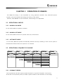

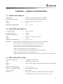
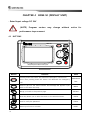

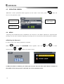
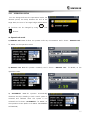
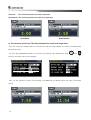

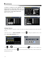
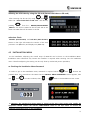
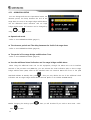
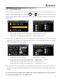
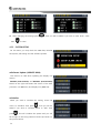

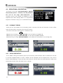

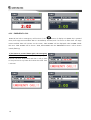
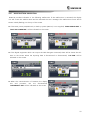
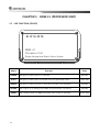


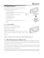


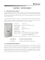
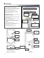
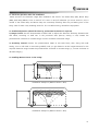
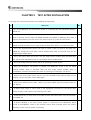
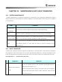


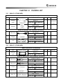
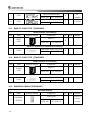
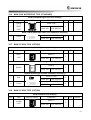
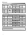
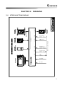
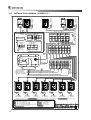
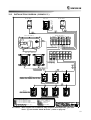
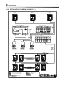
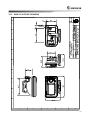

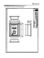
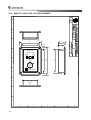
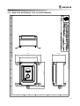
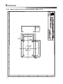
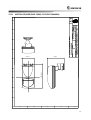
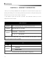

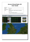

![[CTW100]](http://vs1.manualzilla.com/store/data/005810894_1-66009d11f3039a8ae7d003a87ac83c2b-150x150.png)