1
1
Connection of the SINAMICS S120 to ___________________
Definitions and warnings
the Technology CPU
SIMATIC
S7-300
Connection of the SINAMICS S120
to the Technology CPU
Product Information
09/2011
A5E00480378-04
SINAMICS S120
2
___________________
automation components
3
___________________
Commissioning
4
___________________
Basic functions
5
___________________
Expert Functions
Safety Integrated Functions
6
___________________
in SINAMICS Drive Systems
Legal information
Legal information
Warning notice system
This manual contains notices you have to observe in order to ensure your personal safety, as well as to prevent
damage to property. The notices referring to your personal safety are highlighted in the manual by a safety alert
symbol, notices referring only to property damage have no safety alert symbol. These notices shown below are
graded according to the degree of danger.
DANGER
indicates that death or severe personal injury will result if proper precautions are not taken.
WARNING
indicates that death or severe personal injury may result if proper precautions are not taken.
CAUTION
with a safety alert symbol, indicates that minor personal injury can result if proper precautions are not taken.
CAUTION
without a safety alert symbol, indicates that property damage can result if proper precautions are not taken.
NOTICE
indicates that an unintended result or situation can occur if the relevant information is not taken into account.
If more than one degree of danger is present, the warning notice representing the highest degree of danger will
be used. A notice warning of injury to persons with a safety alert symbol may also include a warning relating to
property damage.
Qualified Personnel
The product/system described in this documentation may be operated only by personnel qualified for the specific
task in accordance with the relevant documentation, in particular its warning notices and safety instructions.
Qualified personnel are those who, based on their training and experience, are capable of identifying risks and
avoiding potential hazards when working with these products/systems.
Proper use of Siemens products
Note the following:
WARNING
Siemens products may only be used for the applications described in the catalog and in the relevant technical
documentation. If products and components from other manufacturers are used, these must be recommended
or approved by Siemens. Proper transport, storage, installation, assembly, commissioning, operation and
maintenance are required to ensure that the products operate safely and without any problems. The permissible
ambient conditions must be complied with. The information in the relevant documentation must be observed.
Trademarks
All names identified by ® are registered trademarks of Siemens AG. The remaining trademarks in this publication
may be trademarks whose use by third parties for their own purposes could violate the rights of the owner.
Disclaimer of Liability
We have reviewed the contents of this publication to ensure consistency with the hardware and software
described. Since variance cannot be precluded entirely, we cannot guarantee full consistency. However, the
information in this publication is reviewed regularly and any necessary corrections are included in subsequent
editions.
Siemens AG
Industry Sector
Postfach 48 48
90026 NÜRNBERG
GERMANY
A5E00480378-04
Ⓟ 09/2011
Copyright © Siemens AG 2011.
Technical data subject to change
Table of contents
1
Definitions and warnings............................................................................................................................ 7
2
SINAMICS S120 automation components ................................................................................................. 9
3
2.1
System overview ............................................................................................................................9
2.2
Control unit.....................................................................................................................................9
2.3
Line Modules................................................................................................................................10
2.4
Motor Modules .............................................................................................................................10
2.5
Expansion and system components ............................................................................................11
2.6
Determining the firmware version number...................................................................................11
2.7
SINAMICS Support Packages .....................................................................................................13
Commissioning ........................................................................................................................................ 15
3.1
Commissioning procedure ...........................................................................................................15
3.2
3.2.1
3.2.2
3.2.3
3.2.4
Connecting hardware components ..............................................................................................15
PROFIBUS interconnection .........................................................................................................15
Interconnection of the DRIVE-CLiQ components ........................................................................17
Additional hardware wiring for Smart Line Modules without DRIVE-CLiQ ..................................21
Special features of the SINAMICS S120 Training Case..............................................................22
3.3
3.3.1
3.3.2
3.3.3
3.3.4
Preparing the connection to the SINAMICS ................................................................................23
Overview ......................................................................................................................................23
Creating a STEP 7 project ...........................................................................................................23
Configuring in HW Config ............................................................................................................24
Activating routing in NetPro .........................................................................................................30
3.4
3.4.1
3.4.2
3.4.3
3.4.4
3.4.5
3.4.6
Configuring the drive components ...............................................................................................35
Overview ......................................................................................................................................35
Automatic configuring ..................................................................................................................35
Manual configuring.......................................................................................................................39
Alignment of the PROFIdrive message frames ...........................................................................69
Loading the configuration into the drive components ..................................................................70
Optimizing the speed controller in the drive.................................................................................71
3.5
3.5.1
3.5.2
Diagnosing the SINAMICS configuration.....................................................................................75
Checking the DRIVE-CLiQ wiring online .....................................................................................75
Drive test using the SINAMICS control panel ..............................................................................76
3.6
3.6.1
3.6.2
Creating technology objects.........................................................................................................78
Creating and configuring axes .....................................................................................................78
Technology Objects Management (TOM)....................................................................................85
3.7
3.7.1
3.7.2
3.7.3
Diagnosing the technology configuration.....................................................................................87
Overview ......................................................................................................................................87
Preparations.................................................................................................................................87
Axis test using the technology axis control panel ........................................................................89
Connection of the SINAMICS S120 to the Technology CPU
Product Information, 09/2011, A5E00480378-04
3
Table of contents
3.8
3.8.1
3.8.2
4
5
Creating the user program .......................................................................................................... 91
Using technology functions ......................................................................................................... 91
Special considerations for the use of an Active Line Module ..................................................... 91
Basic functions......................................................................................................................................... 93
4.1
4.1.1
4.1.2
4.1.3
4.1.4
4.1.5
4.1.6
4.1.7
Encoder settings ......................................................................................................................... 93
Encoder configuration (overview) ............................................................................................... 93
Characteristic values for encoders.............................................................................................. 93
Structure of the encoder actual values ....................................................................................... 95
Encoder types ............................................................................................................................. 99
Encoder mode........................................................................................................................... 100
Setting encoder parameters in the technology ......................................................................... 100
Display of the encoder parameters in S7T Config .................................................................... 102
4.2
4.2.1
4.2.2
4.2.3
4.2.4
4.2.5
4.2.6
Homing ...................................................................................................................................... 104
Homing possibilities .................................................................................................................. 104
Example: Active homing with homing output cam and encoder zero mark .............................. 105
Example: Active homing using only an external zero mark ...................................................... 109
Example for active homing with one of the external zero marks mirrored on the T-CPU......... 114
Example: Active homing using only an encoder zero mark ...................................................... 117
Absolute encoder adjustment with the control panel ................................................................ 120
4.3
Triggering of the integrated outputs of the CU 320 Control Unit............................................... 122
Expert Functions.................................................................................................................................... 127
5.1
5.1.1
5.1.2
PROFIdrive message frame...................................................................................................... 127
Message frame types................................................................................................................ 127
Example: telegram 105 ............................................................................................................. 129
5.2
5.2.1
5.2.2
5.2.3
5.2.4
Extending a PROFIdrive message frame ................................................................................. 130
Address areas ........................................................................................................................... 130
Extending a message frame by creating additional components ............................................. 131
Extending the PROFIdrive message frame in S7T Config ....................................................... 138
Extending an existing PROFIBUS message frame for the drive .............................................. 139
5.3
Disabling the PROFIBUS Sign-of-Life Monitoring .................................................................... 145
5.4
5.4.1
5.4.2
Activating a Second Encoder .................................................................................................... 146
Using a Second Encoder .......................................................................................................... 146
Connecting a second encoder in SINAMICS ............................................................................ 148
5.5
5.5.1
Reading the drive parameters................................................................................................... 150
Example: Reading several parameters using "MC_ReadDriveParameter" .............................. 150
5.6
5.6.1
5.6.2
5.6.3
Measuring Function................................................................................................................... 152
Use Cases................................................................................................................................. 152
Measuring using the integrated inputs on the CU320............................................................... 156
Fetching the measuring inputs using the TM17 terminal module ............................................. 159
5.7
Triggering an output cam using the TM17 terminal module ..................................................... 165
5.8
5.8.1
5.8.2
5.8.3
Triggering of a brake ................................................................................................................. 174
Vertical axis application case .................................................................................................... 174
Activating braking sequential control in SINAMICS .................................................................. 174
Activating braking sequential control in the axis ....................................................................... 176
Connection of the SINAMICS S120 to the Technology CPU
4
Product Information, 09/2011, A5E00480378-04
Table of contents
6
Safety Integrated Functions in SINAMICS Drive Systems ..................................................................... 183
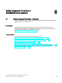
6.1
Safety Integrated Functions - Overview.....................................................................................183
6.2
Safety Integrated functions in SINAMICS S120 drive systems .................................................184
6.3
6.3.1
6.3.2
6.3.3
6.3.4
6.3.5
Support of SINAMICS Safety Integrated functions by the T(F)-CPU ........................................186
Support of the SINAMICS Safety Integrated functions - Overview............................................186
Activating the support of SINAMICS Safety Integrated functions..............................................187
Message frame structure ...........................................................................................................188
Extension of actual value message frame in S7T Config ..........................................................190
Configuration data of the Axis technology object.......................................................................194
6.4
Safety status displays and error messages ...............................................................................195
6.5
Behavior and reactions in the user program..............................................................................198
6.6
Safety Integrated functions without configured support of the extended functions ...................202
6.7
Control via PROFIsafe ...............................................................................................................203
Connection of the SINAMICS S120 to the Technology CPU
Product Information, 09/2011, A5E00480378-04
5
Table of contents
Connection of the SINAMICS S120 to the Technology CPU
6
Product Information, 09/2011, A5E00480378-04
Definitions and warnings
1
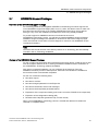
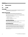
Purpose of document
This document presents the most important standard options to use the
SINAMICS S120 drive system on the CPU 31xT-2 DP Technology CPU.
Other functions can definitely also run together with SINAMICS S120,
but they must be considered individually.
Document scope
● CPU 31xT(F) as of V2.7/5.1.5
● SINAMICS S120 as of V2.6.2
● S7 Technology as of V4.2 SP1
Required basic knowledge
To understand this document you must have general knowledge about automation and
drive technology. In particular, you must be familiar with the SINAMICS S120 drive system.
In addition, you must know how to work with the STEP 7 basic software and the
S7 Technology option package.
Getting Started "CPU 317T-2 DP: Controlling a SINAMICS S120" is provided as
an introduction.
Qualified personnel
Qualified personnel with regard to the documentation are those persons responsible for the
installation, assembly, commissioning, operation and maintenance of the Technology CPU
and SINAMICS S120 product and who have the following qualifications:
● Trained and authorized to energize, de-energize, clear, ground and tag circuits and
equipment in accordance with established safety procedures.
● Trained in the proper care and use of protective equipment in accordance with
established safety procedures.
● First aid training.
Warnings are not explicitly given in this documentation. However, explicit reference is made
to the warning notes in the operating instructions for the associated product of the
SINAMICS series.
Document scope
This description does not replace the device documentation for SINAMICS S120.
A complete description of the SINAMICS S120 function scope is contained in the function
description.
Information on SIMATIC and SINAMICS products is available on the Internet
(http://www.siemens.com/automation/service&support).
Connection of the SINAMICS S120 to the Technology CPU
Product Information, 09/2011, A5E00480378-04
7
Definitions and warnings
Connection of the SINAMICS S120 to the Technology CPU
8
Product Information, 09/2011, A5E00480378-04
SINAMICS S120 automation components
2.1
2
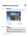
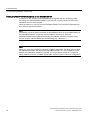
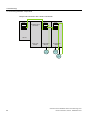
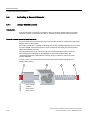
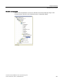
System overview
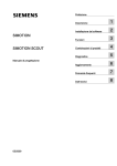
Because SINAMICS S120 can be used to solve sophisticated drive tasks for a very wide
spectrum of industrial applications, it is constructed as a modular system. From the large
number of matched components and functions, users combine just those units that best
match their requirements.
Legend:
2.2
1
Control unit
5
Double Motor Module
2
Active Line Module
6
Terminal Board
3
Smart Line Module
7
Sensor Module Cabinet
4
Single Motor Module
8
Terminal Module
Control unit
In a CU320 Control Unit, the communications, open- and closed-loop functions execute for
one or more Motor Modules and Active Line Modules. The Control Unit is designed for
multi-axis operation.
Note
Only the CU 320(-2 DP) and CU 310 Control Units are supported when using the
SINAMICS S120 drive system in connection with the technology CPU.
Connection of the SINAMICS S120 to the Technology CPU
Product Information, 09/2011, A5E00480378-04
9
SINAMICS S120 automation components
2.3 Line Modules
2.3
Line Modules
The Line Modules perform the function of the central energy infeed for the DC link.
The following Line Modules are available:
● The Active Line Module (ALM) is a self-controlled infeed/regenerative feedback unit for
creating a regulated DC link voltage. This decouples the connected Motor Modules from
the supply voltage and fluctuations within the permitted supply tolerances do not have
any effect on the motor voltage.
The Active Line Module communicates via DRIVE-CLiQ with the CU320 control unit.
● The Basic Line Module (BLM) is an infeed unit that cannot actively regenerate into the
supply. This means that it can only be used for those applications in which the energy
exchange takes place between the motor- and the generator-driven axes in the DC link.
The Basic Line Module communicates via DRIVE-CLiQ with the CU320 control unit.
● The Smart Line Module (SLM) is a non-regulated infeed/regenerative feedback unit with
100% regenerative continuous capability. The regenerative capability of the module can
be deactivated using a digital input.
Certain SLM types have a DRIVE-CLIQ interface (usually starting with 16 Kw).
The Smart Line Modules with DRIVE-CLIQ interface are treated like Active Line Modules
(see Interconnection of the DRIVE-CLiQ components (Page 17)). The control of the
modules without DRIVE-CLIQ interface must be implemented with hard wiring
(see Additional hardware wiring for Smart Line Modules without DRIVE-CLiQ (Page 21)).
2.4
Motor Modules
The Motor Modules operate as inverters and are available for various output currents and in
various performance classes. They obtain the energy for the motors from the DC link of the
attached Line Module.
The following Motor Module classes for controlling the motors are available for the
SINAMICS S120:
● Single Motor Modules in single-axis design in booksize format
● Double Motor Modules in two-axis design in booksize format
Connection of the SINAMICS S120 to the Technology CPU
10
Product Information, 09/2011, A5E00480378-04
SINAMICS S120 automation components
2.5 Expansion and system components
2.5
Expansion and system components
Expansion and system components can be used to expand the
SINAMICS S120 base system so that it can perform functions directly in the drive system,
record encoder signals, etc.
Components
For example, the following components are available for SINAMICS S120:
● The Terminal Board TB30 can be used to expand the CU320 control unit with
additional digital and analog inputs/outputs.
● You require the Sensor Module Cabinet-Mounted SMC10, SMC20, SMC30 when a motor
is to be used without the DRIVE-CLiQ interface or an additional external encoder is
to be attached to the drive system.
● The communication board CB10 provides an interface between the control unit
CU320 and a CAN bus system.
● The CBE30 communication board provides an interface between the
CU320 control unit and a PROFINET system.
● The Terminal Modules TM15, TM17, and TM41 provide additional inputs/outputs with
extended functionality (High Feature) that can be used as an output cam or measuring
input in the technology. Terminal modules are connected directly to the
CU 320 control unit by means of the DRIVE-CLiQ interface.
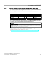
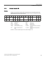
2.6
Determining the firmware version number
The SINAMICS S120 firmware can generally be determined in various ways.
What is important is whether a configuration already exists in S7T Config.
Determining the firmware version of the SINAMICS S120 from the CF Card
The version number of the SINAMICS S120 is stored on the Compact Flash Card.
The firmware of the SINAMICS S120 must be read from the CF Card when the firmware of
the SINAMICS S120 is not known and no current configuration is available in S7T Config.
The CF Card contains the "CONTENT.txt" file in the root directory. The
"internal version 02.20.28.00" line shows the currently loaded firmware.
The number 02.20.28.00 shown in this example is the current version number
of the firmware.
Connection of the SINAMICS S120 to the Technology CPU
Product Information, 09/2011, A5E00480378-04
11
SINAMICS S120 automation components
2.6 Determining the firmware version number
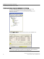
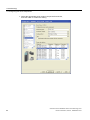
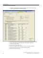
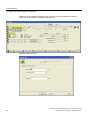
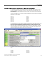
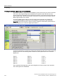
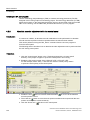
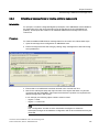
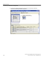
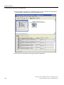
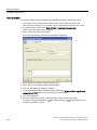
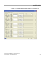
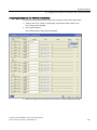
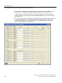
Determining the firmware version of the SINAMICS S120 in S7T Config
If a current configuration of the SINAMICS S120 is available in S7T Config,
the firmware of the SINAMICS S120 can be determined as follows.
Select in the project navigator for S7T Config the appropriate SINAMICS S120.
Double-click "Overview".
Open the Version overview tab. Take the firmware version of the SINAMICS S120
from this table.
Note
Ensure that your configuration is consistent in S7T Config online. This is necessary to
ensure that the firmware versions shown here can be loaded online.
Connection of the SINAMICS S120 to the Technology CPU
12
Product Information, 09/2011, A5E00480378-04
SINAMICS S120 automation components
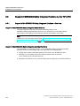
2.7 SINAMICS Support Packages
2.7
SINAMICS Support Packages
Definition of the SINAMICS Support Package
S7 Technology features the integrated STARTER commissioning tool which supports the
use of SINAMICS Support Packages (SSP) as of V4.1 SP2. This allows users to make new
drive firmware versions known to an existing STARTER/S7-Technology version without
having to carry out a new installation and without the drive being actually available.
To provide support for SINAMICS versions not included in the current
STARTER/S7 Technology version, you will have to install a SINAMICS Support Package.
SINAMICS Support Packages are available for download on the Product Support pages.
Users are informed of new SSPs in Product Support as soon as a new SINAMICS version
is released for delivery.
Note
The SSPs that exist at the time of the delivery release of S7 Technology are automatically
included in the S7 Technology installation.
Content of the SINAMICS Support Package
An SSP contains only description files of the devices and drive objects. Install an SSP to add
new drive objects and devices to an existing STARTER installation without modification of
the STARTER/S7-Technology software installation.
After having completed installation, you can configure all the functions of the new
SINAMICS version by means of the Expert list. All screens and wizards are available for
the functions which are downward compatible.
An SSP can contain the following items:
● New drive objects
● New device versions
● New and changed parameters in the Expert list
● New and revised faults, alarms and messages
● New and revised sequential parameterizations
● Expansions of the component catalog (new motors, encoders, DRIVE-CLiQ components)
● Expansion of the configuration catalog (SD)
● Revised Online Help files (parameter help, function charts)
When a new STARTER/S7-Technology version is created and delivered it contains all
released or compatible SSPs.
Connection of the SINAMICS S120 to the Technology CPU
Product Information, 09/2011, A5E00480378-04
13
SINAMICS S120 automation components
2.7 SINAMICS Support Packages
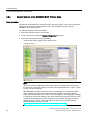
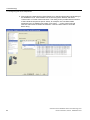
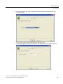
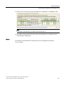
Installation
All SSPs released for a product version can be installed in any order.
Do not run STARTER/S7 Technology during SSP installation.
To install a new SSP from CD, follow these steps:
1. Place the SSP CD into the CD drive of your programming device/PC,
or save and unpack the SSP you downloaded from Product Support.
2. Select and run setup.exe in Windows Explorer
3. Follow the installation instructions and restart the computer after successful installation.
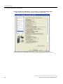
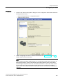
After having successfully completed installation, you can open S7T Config to configure the
SINAMICS versions you installed in offline mode, or to operate them in online mode
(for example, by selecting "Accessible nodes").
The SINAMICS Support Packages you installed are displayed as "SSP SINAMICS ..."
in SIMATIC > Product Information > Installed Software , "Components" tab.
Connection of the SINAMICS S120 to the Technology CPU
14
Product Information, 09/2011, A5E00480378-04
3
Commissioning
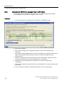
3.1
Commissioning procedure
Operational sequence
The commissioning procedure is divided into two parts:
1. Create a STEP 7 project and make the settings of the technology CPU for the connected
hardware using the HW Config and S7T Config programs. Special attention is placed on
the parameterizations that must be performed both in the technology CPU and in the
SINAMICS S120.
2. Parameterize SINAMICS S120, create drives and axes. The base device commissioning
required for the connection to the technology CPU is also described here.
The following sections describe these settings in detail, both for the technology CPU as well
as the SINAMICS S120.
3.2
Connecting hardware components
3.2.1
PROFIBUS interconnection
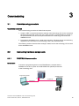
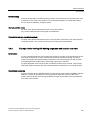
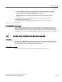
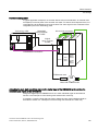
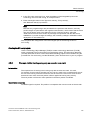
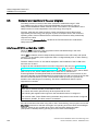
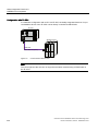
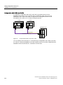
Introduction
Connect the programming device to the PROFIBUS X1 terminal and the
SINAMICS S120 drive system to the PROFIBUS DP (DRIVE) X3 terminal
of the Technology CPU.
7HFKQRORJ\&38
3URJUDPPLQJGHYLFH
6,1$0,&66
;
;
'3'5,9(
352),%86
Connection of the SINAMICS S120 to the Technology CPU
Product Information, 09/2011, A5E00480378-04
15
Commissioning
3.2 Connecting hardware components
Setting of a fixed PROFIBUS address on the SINAMICS S120
In general, for the operation of the SINAMICS S120 together with the Technology CPU,
the setting of a fixed PROFIBUS address using the DIP or rotary switches directly on the
SINAMICS S120 is recommended.
When the values 0 or 127 are set, the PROFIBUS address set in the p0918 parameter will
be is used for the communication.
Note
The address 126 in the p0918 parameter of the SINAMICS S120 is set as default setting of
the PROFIBUS address. To prevent access problems caused by an unknown
PROFIBUS address during the commissioning, the address should be predefined using
the DIP or rotary switches before the commissioning (e.g. "address 4").
Note
When you use a CB10 (CAN bus interface) or CBE20 (PROFINET interface) option module,
the SINAMICS firmware switches off the PROFIBUS interface. It is not possible to run two
different communication interfaces in parallel. It is not possible to switch off a configured
CB10 (CAN bus interface) or CBE20 (PROFINET interface) option module via configuration.
Connection of the SINAMICS S120 to the Technology CPU
16
Product Information, 09/2011, A5E00480378-04
Commissioning
3.2 Connecting hardware components
3.2.2
Interconnection of the DRIVE-CLiQ components
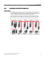
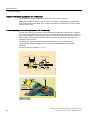
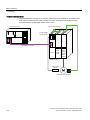
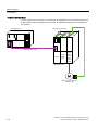
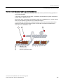
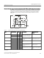
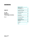
System overview
The SINAMICS S120 components are connected with each other using an integrated bus
system, the DRIVE-CLiQ. Not only can be the individual modules of the drive system,
such as Line Modules and Motor Modules, connected with the Control Unit, but also motor
encoders or external encoders can be connected with the Motor Modules.
Conversion modules (Sensor Module Cabinet) for the conversion of traditional encoder
signals on DRIVE-CLiQ are available for non-Siemens motors and retrofit applications.
The following figure shows a sample configuration with different system components.
&8
/LQH0RGXO
0RWRU0RGXO
0RWRU0RGXO
0RWRU0RGXO
60&
60&
0RWRU0RGXO
60&
70
'LJLWDODQDORJ
SHULSKHUDOV
0RWRUZLWK
'5,9(&/,4
LQWHUIDFH
0RWRUZLWKRXW
'5,9(&/,4
LQWHUIDFH
'5,9(&/,4
HQFRGHU
&RQYHQWLRQDO
HQFRGHU77/+7/
Connection of the SINAMICS S120 to the Technology CPU
Product Information, 09/2011, A5E00480378-04
17
Commissioning
3.2 Connecting hardware components
Rules for the interconnection of DRIVE-CLiQ components
To work with DRIVE-CLiQ technology and to use technology functions,
e.g. the automatic topology recognition, certain rules must be followed for the
commissioning of the SINAMICS S120 drive system. A distinction is made here between
mandatory DRIVE-CLiQ rules that must be adhered to without exception and
recommended rules that should be observed to avoid having to change the
topology created offline in S7T Config. The most important rules are explained briefly in
the following:
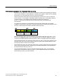
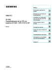
Mandatory DRIVE-CLiQ rules for CU 320-2 and higher
The mandatory rules are a prerequisite for error-free operation. The following rules are
generally applicable, provided they are not subject to limitations according to the firmware
version:
● Observe the maximum number of nodes:
– maximum 8 components in series
– maximum 16 on a DRIVE-CLiQ line of the Control Unit
● No duplicated wiring
● No ring wiring
● Only one Active Line Module for each CU320 Control Unit
● Double Motor Module not as single drive
● Max. 9 Sensor Modules
● Preset sampling times must be retained
The following figure illustrates the rules using a DRIVE-CLIQ line as an example.
&8
;
;
;
;
1RULQJZLULQJ
1RGXSOLFDWHGZLULQJ
The maximum permitted number of SINAMICS S120 drive objects depends on the firmware
version used.
Connection of the SINAMICS S120 to the Technology CPU
18
Product Information, 09/2011, A5E00480378-04
Commissioning
3.2 Connecting hardware components
Recommended DRIVE-CLiQ rules
When the recommended rules for DRIVE-CLiQ wiring are observed, the components will be
automatically assigned to the drives during online configuration or during topology
recognition.
Note
Complete, detailed information about these rules is contained in the documentation for the
SINAMICS S120 drive system available on the Internet
(http://apps01.industry.siemens.com/content/00000100/Content/syn_s120.aspx?rc=1).
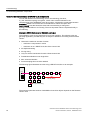
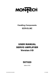
Examples
Sample interconnection with an Active Line Module:
;
;
;
;
;
;
;
;
;
;
;
;
;
;
;
&8
$FWLYH/LQH
0RGXOH
6LQJOH0RWRU
0RGXOH
0RWRU
(QFRGHU
'RXEOH0RWRU
0RGXOH
0RWRU
(QFRGHU
0RWRU
(QFRGHU
Connection of the SINAMICS S120 to the Technology CPU
Product Information, 09/2011, A5E00480378-04
19
Commissioning
3.2 Connecting hardware components
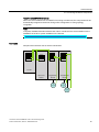
Sample interconnection with a Smart Line Module:
;
;
;
1R'5,9(&/L4
FRQQHFWLRQ
;
;
;
;
;
;
;
;
;
&8
6PDUW/LQH
0RGXOH
6LQJOH0RWRU
0RGXOH
0RWRU
(QFRGHU
'RXEOH0RWRU
0RGXOH
0RWRU
(QFRGHU
0RWRU
(QFRGHU
Connection of the SINAMICS S120 to the Technology CPU
20
Product Information, 09/2011, A5E00480378-04
Commissioning
3.2 Connecting hardware components
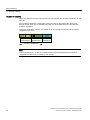
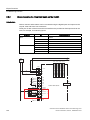
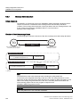
3.2.3
Additional hardware wiring for Smart Line Modules without DRIVE-CLiQ
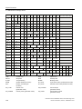
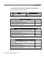
For Smart Line Modules without a DRIVE-CLiQ interface, the signals of these modules must
be connected through hardware wiring with the CU320 control unit.
The following signals must be wired between the Smart Line Module (SLM) and the
CU320 control unit.
Signal
SLM
TB30
Comment
SLM Ready
DO: X21.1
⇨
DI: X481.1
SLM operational
Overtemperature
Prewarning
DO: X21.2
⇨
DI: X481.3
Overtemperature
prewarning
Reset
DI: X22.3
⇦
DO: X481.5
Reset faults
The wiring using the TB30 Terminal Board on the SINAMICS S120 was realized in the table.
As an alternative to the wiring using the digital inputs of the TB30 Terminal Board, the wiring
can also be made directly at the digital inputs of the CU320 control unit.
CAUTION
Damage to the infeed.
If the operational signal of the Smart Line Module (SLM) is not wired to the control unit and
evaluated there, this can cause damage to the infeed.
Detailed information on the wiring is available in the documentation on the
SINAMICS S120 drive system available on the Internet
(http://apps01.industry.siemens.com/content/00000100/Content/syn_s120.aspx?rc=1).
Connection of the SINAMICS S120 to the Technology CPU
Product Information, 09/2011, A5E00480378-04
21
Commissioning
3.2 Connecting hardware components
3.2.4
Special features of the SINAMICS S120 Training Case
Basic procedure
The devices are designed for use with the 230 V AC power supply, so you must change the
setting for the device connection voltage of the motor modules if you are using the
SINAMICS S120 Training Case.
To change the setting, follow these steps:
1. Select the respective drive in S7T Config.
2. In the context menu, select the Experts > Expert List command.
3. There you change the following parameters:
– "p210 device supply voltage" to the value "400 V"
– "p1248" to "244"
Note
The motor modules integrated into the training case were adapted at the factory for
the 230 V AC connection voltage up to order number MLFB 6SL3120 - xTE13 - 0AA2,
so they cannot be replaced.
With SINAMICS firmware version V2.5 SP1 x x and higher, it is possible to replace
motor modules but only in conjunction with motor modules with DAC processors
(order number MLFB 6SL3120 - xTE13 - 0AA3 and higher). The configuration settings
to change the connection voltage to 230 V AC are done in the expert list for the motor
module. If the training case you are using has motor modules with DAC processors
(MLFB 6SL3120 - xTE13 - 0AA3 and higher), make sure you read the following
additional information on the Internet
(http://support.automation.siemens.com/WW/view/en/27038754).
Connection of the SINAMICS S120 to the Technology CPU
22
Product Information, 09/2011, A5E00480378-04
Commissioning
3.3 Preparing the connection to the SINAMICS
3.3
Preparing the connection to the SINAMICS
3.3.1
Overview
Introduction
To establish a connection for the configuring of the SINAMICS S120 between the
programming device and the drive system, several preliminary tasks must be performed;
these tasks are discussed in detail in the following sections.
3.3.2
Creating a STEP 7 project
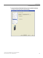
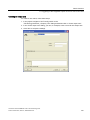
Procedure
To create a new project, start the SIMATIC Manager and use the File > New menu
command to create a new project, for example, a project with the name DSC_SINAMICS.
Then use the Insert > Station > SIMATIC 300 station menu command to add a new
S7 300 station.
Connection of the SINAMICS S120 to the Technology CPU
Product Information, 09/2011, A5E00480378-04
23
Commissioning
3.3 Preparing the connection to the SINAMICS
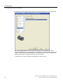
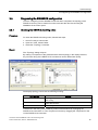
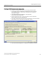
3.3.3
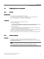
Configuring in HW Config
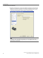
Introduction
Now double-click the "Hardware" element to configure the hardware of the
SIMATIC 300 station using the HW Config tool.
Technology CPU: configuring the hardware
1. Select the "SIMATIC Technology CPU" hardware catalog and add there a mounting rail
with drag-and-drop to the configuration.
2. Then give the mounting rail at slot 1 a power supply, e.g. PS 307 2A, the mounting rail
at slot 2 a CPU, e.g. the Technology CPU 317T-2 DP.
Note
When you add the Technology CPU, pay attention to the firmware version or the order
number of the CPU that is located on the front panel of the CPU.
3. Click OK to confirm the displayed message for downloading the system data when the
Technology CPU is added.
Connection of the SINAMICS S120 to the Technology CPU
24
Product Information, 09/2011, A5E00480378-04
Commissioning
3.3 Preparing the connection to the SINAMICS
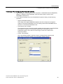
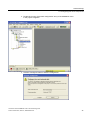
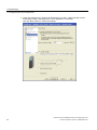
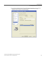
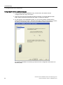
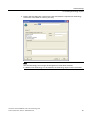
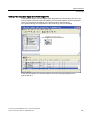
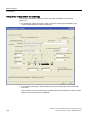
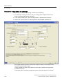
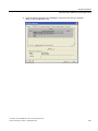
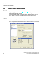
Technology CPU: Configuring PROFIBUS DP (DRIVE)
1. After selecting the Technology CPU, the "Properties - PROFIBUS interface DP(DRIVE)
(R0/S3.1)" dialog box will be displayed. Click the "New" button to create a new
PROFIBUS network there.
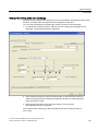
2. In the "Network settings" tab of the "PROFIBUS Properties" dialog, set the following
properties:
– Highest PROFIBUS address: 2
The setting of the highest PROFIBUS address should correspond to the highest
address of an active PROFIBUS node. This setting reduces the PROFIBUS time to
search for a new active PROFIBUS node.
– Transmission rate: 12 Mbps
This transmission rate permits the largest possible data throughput on the PROFIBUS.
Pay attention, however, to the maximum transmission rate of the CP in the
programming device. If the value is set too large, access to the CPU will no
longer be possible.
– Profile: "User-defined"
The "user-defined" setting is required, when a message frame extension with
BICO wiring is required in addition to the standard message frames.
Connection of the SINAMICS S120 to the Technology CPU
Product Information, 09/2011, A5E00480378-04
25
Commissioning
3.3 Preparing the connection to the SINAMICS
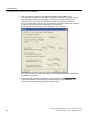
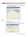
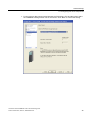
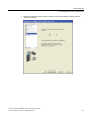
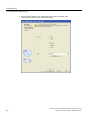
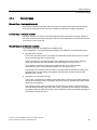
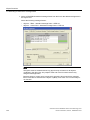
3. Click the "Options" button to make additional settings for PROFIBUS. In the
"Constant bus cycle time" tab, activate the "Activate constant bus cycle time" function.
Also activate the "Slave Synchronization" to keep the time values identical for all
connected slaves. Then click the "Recalculate" button to calculate the constant
DP cycle time and the Ti and To times. Round up the calculated constant DP cycle time
(0.250 ms step) and enter the rounded value in the input box.
Recommended rounded values are, for example, 1.5 ms or 2.0 ms.
Click the "OK" button to confirm the settings. The configured objects are then added to
the SIMATIC 300 station.
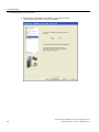
4. To automatically generate the technology system data, open the object properties
in the shortcut menu of the technology. In the "Technology system data" tab,
activate the "Generate technology system data" function.
Connection of the SINAMICS S120 to the Technology CPU
26
Product Information, 09/2011, A5E00480378-04
Commissioning
3.3 Preparing the connection to the SINAMICS
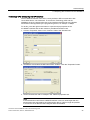
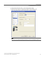
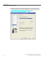
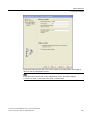
Technology CPU: configuring the MPI interface
The X1-MPI/DP interface of the CPU is set by default to MPI communication with
187.5 KBit/s and to "not networked". To access the Technology CPU and the
SINAMICS S120, the transmission rate of the interface should be set to the highest
transmission rate supported by the programming device, for example 12 Mbps.
To do this, press the right mouse button to open the object properties of the
X1-MPI/DP interface and set the maximum possible transmission rate:
1. Click the "Properties" button in the "Interface" field of the "General" tab.
2. Set address 2 and select the MPI subnet from "Subnet". Click the "Properties" button.
3. Set the transmission rate to 12 Mbps in the "Network properties" tab.
Note
If the transmission rate of the X1-MPI/DP interface is set to a value larger than the
transmission rate supported by the programming device, it will no longer be possible
to access the CPU after the HW Config has been downloaded.
Connection of the SINAMICS S120 to the Technology CPU
Product Information, 09/2011, A5E00480378-04
27
Commissioning
3.3 Preparing the connection to the SINAMICS
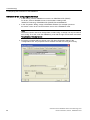
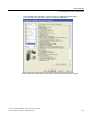
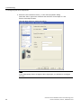
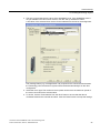
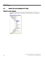
SINAMICS S120: configuring the hardware
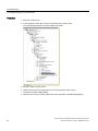
1. In HW Config, insert a SINAMICS S120 drive on PROFIBUS-DP (DRIVE).
To do this, select a SINAMICS S120 in the hardware catalog under
"SIMATIC-Technology \PROFIBUS DP (DRIVE) \Drives\SINAMICS".
2. In the "Properties" dialog, assign a PROFIBUS address (for example 4) and set
the device version to the current firmware version of the SINAMICS S120.
Note
The device version cannot be changed later in HW Config. A change can only be made in
S7T Config. To do this, mark the SINAMICS_S120 with the right mouse button and select
Target device > Device version.
3. Accept the properties without change in the "DP Slave Properties" dialog in the
"Configuration" tab. The properties can be entered at a later time using S7T Config.
Connection of the SINAMICS S120 to the Technology CPU
28
Product Information, 09/2011, A5E00480378-04
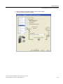
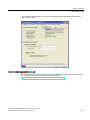
Commissioning
3.3 Preparing the connection to the SINAMICS
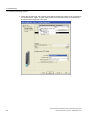
4. In the "Isochronous operation" tab, activate isochronous operation for this slave.
Then click the "Align" button to perform the isochronous alignment of the slave with the
Technology CPU.
5. Click "OK" to accept the settings.
Saving and compiling the project
Save and compile the hardware configuration and load the project into the attached
Technology CPU.
Note
If an error message appears during the save and compile, check the settings for Ti and To in
the PROFIBUS DP (DRIVE) options. The times must be a multiple of the 0.250 ms interval.
Connection of the SINAMICS S120 to the Technology CPU
Product Information, 09/2011, A5E00480378-04
29
Commissioning
3.3 Preparing the connection to the SINAMICS
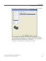
3.3.4
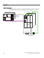
Activating routing in NetPro
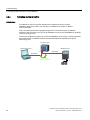
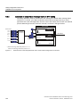
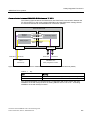
Introduction
To establish an online connection between the programming device and the
SINAMICS S120 drive system, the "Routing of a SIMATIC PC station" in NetPro
must be activated.
This is necessary because the programming device is connected via the X1-MPI/DP
interface to the technology CPU and to the SINAMICS S120 on the PROFIBUS DP (DRIVE)
of the Technology CPU.
To allow the programming device to access the SINAMICS S120 online, a routing must take
place between the X1-MPI/DP interface and the PROFIBUS DP (DRIVE) through the
Technology CPU.
7HFKQRORJ\&38
3URJUDPPLQJGHYLFH
6,1$0,&66
;
;
'3'5,9(
352),%86
5287,1*
EHWZHHQ;DQG;
Connection of the SINAMICS S120 to the Technology CPU
30
Product Information, 09/2011, A5E00480378-04
Commissioning
3.3 Preparing the connection to the SINAMICS
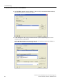
Procedure
To enable routing for the programming device, follow these steps:
1. Open the NetPro program in the SIMATIC Manager with the menu command
Options > Configure Network.
2. Add a PG/PC station from the "Network objects" catalog from the "Stations" directory.
Note
If the SINAMICS S120 is not displayed in NetPro, switch in the View menu to the
"With DP Slave / IO Devices" display.
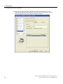
3. Select the PG/PC station and right-click to open the properties.
4. Click the "New" button in the "Interfaces" tab to add an MPI type interface.
Connection of the SINAMICS S120 to the Technology CPU
Product Information, 09/2011, A5E00480378-04
31
Commissioning
3.3 Preparing the connection to the SINAMICS
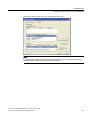
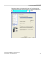
5. As PROFIBUS address, set the address "0" for the PG (recommended default address).
Click the "OK" button to confirm the setting.
6. In the "Assignment" tab, assign the MPI interface of your programming device to the
interface module of the PG/PC.
Select the MPI interface in the upper window and the interface module of the PG/PC in
the middle window and click the "Assign" button.
Connection of the SINAMICS S120 to the Technology CPU
32
Product Information, 09/2011, A5E00480378-04
Commissioning
3.3 Preparing the connection to the SINAMICS
Select the "Active" check box in the "S7Online access" field.
Note
If the project is transferred to a different programming device, this assignment must be
repeated because these settings are device-dependent.
Connection of the SINAMICS S120 to the Technology CPU
Product Information, 09/2011, A5E00480378-04
33
Commissioning
3.3 Preparing the connection to the SINAMICS
Result
The network configuration is now completed. Once again check the MPI address settings of
the PG/PC interface (address 0) and the Technology CPU (address 2) in the overview and
save and compile the network configuration.
Load the configuration into the target device.
The successful activation of the routing function is indicated by the connection of the
PG/PC interface with the MPI network having a yellow background in the overview.
Connection of the SINAMICS S120 to the Technology CPU
34
Product Information, 09/2011, A5E00480378-04
Commissioning
3.4 Configuring the drive components
3.4
Configuring the drive components
3.4.1
Overview
Basic procedure
You configure the drive components in S7T Config.
You open S7T Config by double-clicking the "SINAMICS_S120...\Commissioning"
entry in the SINAMICS_S120... folder in the SIMATIC Manager.
Configuration
The drive components can be configured in two ways:
● Automatic configuration:
S7T Config will automatically detect the topology of the drive system and the components
of the drive system, provided they are equipped with a DRIVE-CLiQ interface.
● Manual configuration:
This requires that the structure of the drive system is created manually and the present
modules selected manually from the configuration lists.
Components not equipped with a DRIVE-CLiQ interface can only be configured manually or,
if necessary, must be set up manually after an automatic configuring.
The two configuring types for the drive components are introduced in the following sections.
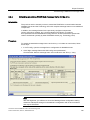
3.4.2
Automatic configuring
Introduction
The automatic configuring can only be performed in online mode of S7T Config.
The existing components of the drive system are entered automatically into the configuration
via the DRIVE-CLiQ connection.
Note
If necessary, components that cannot be selected in the configuration lists with
manual configuration can be detected by S7T Config with automatic configuration.
Connection of the SINAMICS S120 to the Technology CPU
Product Information, 09/2011, A5E00480378-04
35
Commissioning
3.4 Configuring the drive components
Procedure
1. Use the Project > Connect to target system menu command to establish an online
connection to the SINAMICS S120 in S7T Config.
2. Place the SINAMICS S120 in the initial state by restoring the factory settings.
To do this, mark "SINAMICS_S120" and select the
Target device > Restore factory settings menu command in the shortcut menu.
Pay attention to any messages and acknowledge them. Also save the factory settings in
the ROM of the drive.
Connection of the SINAMICS S120 to the Technology CPU
36
Product Information, 09/2011, A5E00480378-04
Commissioning
3.4 Configuring the drive components
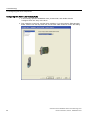
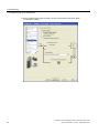
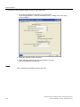
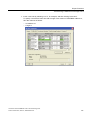
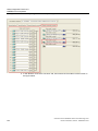
3. Double-click on the "Automatic configuration" entry of the SINAMICS S120
in the project navigation.
4. Click the "Configure" button to start the configuration.
Connection of the SINAMICS S120 to the Technology CPU
Product Information, 09/2011, A5E00480378-04
37
Commissioning
3.4 Configuring the drive components
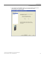
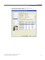
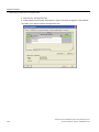
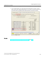
5. Select the type of the drive object. In this example, a servo type drive is to be configured.
To configure the individual drives differently, the type for each drive can be selected
separately in the lower part of the dialog box.
Click the "Create" button to confirm the settings.
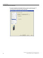
Result
The configuration is created and will be loaded to the programming device.
Switch to offline mode.
This completes the automatic configuration of the drive system.
Components that do not have any DRIVE-CLiQ interface must now be configured manually.
The message is displayed to indicate this and can be acknowledged by clicking "OK".
Connection of the SINAMICS S120 to the Technology CPU
38
Product Information, 09/2011, A5E00480378-04
Commissioning
3.4 Configuring the drive components
3.4.3
Manual configuring
Introduction
The manual configuring can only be performed in offline mode of S7T Config.
The components of the drive system that are present must be configured manually using
S7T Config.
Various infeed modules of the SINAMICS
The procedure to be adopted for the manual configuring depends on the SINAMICS infeed.
Three different types of SINAMICS infeeds are available:
● Active Line Modules (ALM)
● Basic Line Modules (BLM)
● Smart Line Modules (SLM)
The same dialogs are used for configuring of Active Line Module and the Basic Line Module;
the configuring of the Smart Line Module differs in some configuration steps.
Note
The configuring with an Active Line Module (ALM) and the configuring of the
Smart Line Module (SLM) is described separately in the following sections.
Each configuring guide contains all required steps. Therefore, select the appropriate
section for your configuration.
Connection of the SINAMICS S120 to the Technology CPU
Product Information, 09/2011, A5E00480378-04
39
Commissioning
3.4 Configuring the drive components
Configuring with Active Line Module (ALM)
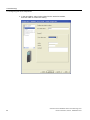
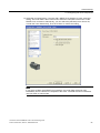
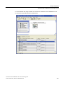
1. In S7T Config, open the SINAMICS S120_CU320 folder, and double-click the
"Configure drive unit" entry or the drive.
2. First create the control unit, and the option modules. If you are using the TB30 terminal
board, select it from the drop-down list, and click the "Next" button to confirm the setting.
Connection of the SINAMICS S120 to the Technology CPU
40
Product Information, 09/2011, A5E00480378-04
Commissioning
3.4 Configuring the drive components
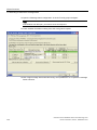
3. For the selection of the SINAMICS infeed, you can choose between modules with or
without DRIVE-CLiQ connection. Select "Yes" for the active line module,
then click "Next" to confirm the setting.
Connection of the SINAMICS S120 to the Technology CPU
Product Information, 09/2011, A5E00480378-04
41
Commissioning
3.4 Configuring the drive components
4. In the next dialog, select "Active infeed" for the active line module,
and click "Next" to confirm the setting.
Connection of the SINAMICS S120 to the Technology CPU
42
Product Information, 09/2011, A5E00480378-04
Commissioning
3.4 Configuring the drive components
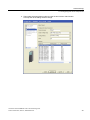
5. Then select the appropriate module from the list and click the "Next" button
to accept the other settings without change.
Connection of the SINAMICS S120 to the Technology CPU
Product Information, 09/2011, A5E00480378-04
43
Commissioning
3.4 Configuring the drive components
6. Check the settings for the line/DC link identification, line filter, voltage sensing module,
and braking module, and adapt them to your application, if necessary.
Click the "Next" button to confirm the settings.
Connection of the SINAMICS S120 to the Technology CPU
44
Product Information, 09/2011, A5E00480378-04
Commissioning
3.4 Configuring the drive components
7. For the process data communiction between the Technology CPU and the infeed, select
the "SIEMENS message frame 370 for the infeed". Click "Next" to confirm the setting.
Connection of the SINAMICS S120 to the Technology CPU
Product Information, 09/2011, A5E00480378-04
45
Commissioning
3.4 Configuring the drive components
8. Now start the configuration of the drive by selecting "Yes" and
clicking the "Next" button to confirm the setting.
Connection of the SINAMICS S120 to the Technology CPU
46
Product Information, 09/2011, A5E00480378-04
Commissioning
3.4 Configuring the drive components
9. Enter the name of the drive "Drive_1" in the "Drive properties" dialog.
10.Select the "Servo" type on the "General" tab. Select the "Drive object no." tab.
Enter a drive object number. Click the "Next" button to confirm the settings.
Note
If you want to set a different operating mode later, you have to reconfigure the drive.
Connection of the SINAMICS S120 to the Technology CPU
Product Information, 09/2011, A5E00480378-04
47
Commissioning
3.4 Configuring the drive components
11.Select "Speed control (with encoder)" as the control method, and click "Next"
to confirm the setting.
Connection of the SINAMICS S120 to the Technology CPU
48
Product Information, 09/2011, A5E00480378-04
Commissioning
3.4 Configuring the drive components
12.Select the appropriate power section component from the list,
and click "Next" to confirm the setting.
Connection of the SINAMICS S120 to the Technology CPU
Product Information, 09/2011, A5E00480378-04
49
Commissioning
3.4 Configuring the drive components
13.If you have configured a Double Motor Module, you must now select the power unit
connection of the motor on the module. For the first motor, select, for example,
the Connection X1. Click "Next" to confirm the setting.
Connection of the SINAMICS S120 to the Technology CPU
50
Product Information, 09/2011, A5E00480378-04
Commissioning
3.4 Configuring the drive components
14.Select the connected motor. If a motor with a DRIVE-CLiQ interface is used, select this
setting. The motor data is then read from the electronic nameplate of the motor via the
DRIVE-CLiQ connection. Alternatively, you can select the (standard) motor from a list,
or enter the motor data directly. Then click "Next" to confirm the setting.
Note
If you select a "Motor with DRIVE-CLiQ interface", the motor data will not be read
immediately from the electronic nameplate of the motor. The data will not be transferred
until you switch to online mode.
Connection of the SINAMICS S120 to the Technology CPU
Product Information, 09/2011, A5E00480378-04
51
Commissioning
3.4 Configuring the drive components
15.Configure the motor holding brake, if there is one, and click "Next" to confirm the setting.
For motor holding brakes which are a direct component of the motor block, use the
"Motor holding brake acc. to sequential control" setting. For externally fitted motor holding
brakes, select the "Motor holding brake acc. to sequential control, brake connection via
BICO interconnection" setting, and also link it to a free output.
In both cases, you must enable the "Extended brake control" option.
Connection of the SINAMICS S120 to the Technology CPU
52
Product Information, 09/2011, A5E00480378-04
Commissioning
3.4 Configuring the drive components
16.If you did not activate encoder sensing via the Drive CLiQ interface, you can select the
relevant encoder from the list box. Select the desired encoder and the encoder
evaluation, then click "Next" to confirm the setting.
Connection of the SINAMICS S120 to the Technology CPU
Product Information, 09/2011, A5E00480378-04
53
Commissioning
3.4 Configuring the drive components
17.For process data communication between the Technology CPU and power section via
PROFIBUS DP (DRIVE), set a suitable message frame, such as message frame 105.
You can find further information about the properties of the individual message frames in
the "Extending a PROFIdrive message frame (Page 130)" chapter.
Click "Next" to confirm the setting.
Connection of the SINAMICS S120 to the Technology CPU
54
Product Information, 09/2011, A5E00480378-04
Commissioning
3.4 Configuring the drive components
This completes the configuration. You can review your parameter settings again
in the summary; click the "Finish" button to close the configuration.
18.Then repeat the configuration for any other motors connected to the drive system.
Connection of the SINAMICS S120 to the Technology CPU
Product Information, 09/2011, A5E00480378-04
55
Commissioning
3.4 Configuring the drive components
Configuring with Smart Line Module (SLM)
1. In S7T Config, open the SINAMICS S120_CU320 folder, and double-click the
"Configure drive unit" entry or the drive.
2. Insert the control unit and optionally the add-on modules, for example TB30 terminal
board. Select the desired values and click "Next" to confirm the settings.
3. For the selection of the SINAMICS infeed, you can choose between modules with or
without DRIVE-CLiQ connection. Select the appropriate setting and click "Next" to confirm
the setting. The following steps are for Smart Line Modules without DRIVE-CLiQ.
For modules with DRIVE-CLiQ infeed, proceed as for the configuration with Active Line
Modules (ALM).
Connection of the SINAMICS S120 to the Technology CPU
56
Product Information, 09/2011, A5E00480378-04
Commissioning
3.4 Configuring the drive components
4. Start the configuration of the drive by selecting "Yes" and clicking the "Next" button to
confirm the setting.
Connection of the SINAMICS S120 to the Technology CPU
Product Information, 09/2011, A5E00480378-04
57
Commissioning
3.4 Configuring the drive components
5. Enter the name of the drive "Drive_1" in the "Drive properties" dialog.
Select the "Servo" type on the "General" tab. Select the "Drive object no." tab.
Enter a drive object number.
Click the "Next" button to confirm the settings.
Note
If you subsequently want to change the drive object type, you will have to reconfigure
the drive.
Connection of the SINAMICS S120 to the Technology CPU
58
Product Information, 09/2011, A5E00480378-04
Commissioning
3.4 Configuring the drive components
6. Select "Speed control (with encoder)" as the control method,
and click "Next" to confirm the setting.
Connection of the SINAMICS S120 to the Technology CPU
Product Information, 09/2011, A5E00480378-04
59
Commissioning
3.4 Configuring the drive components
7. Select the appropriate power section component from the list,
and click "Next" to confirm the setting.
Connection of the SINAMICS S120 to the Technology CPU
60
Product Information, 09/2011, A5E00480378-04
Commissioning
3.4 Configuring the drive components
8. For Smart Line Modules without DRIVE-CLiQ interface, a message appears with
information on the hardware wiring of the ready signals between infeed and the drive.
Read this information and confirm the message with "OK".
Note
For SLM without DRIVE-CLIQ, the hardware wiring of the ready signal for the infeed can
take place either via the digital inputs of the CU 320 control unit or via the additional
digital inputs of the TB 30 terminal board.
The appropriate input of the signal is then used for the subsequent internal wiring
of the BICO signals.
Connection of the SINAMICS S120 to the Technology CPU
Product Information, 09/2011, A5E00480378-04
61
Commissioning
3.4 Configuring the drive components
9. Now perform the internal wiring of the Ready to run signal using the BICO engineering of
the SINAMICS S120. Click the blue icon for the wiring of the binector and select
"Control unit" or "Further interconnections". The dialog for the possible interconnections
of the individual components opens. Select, for example, the "r722 Bit0 CO/BO
parameter here: CU digital inputs, status: DI 0 X122.1…." on the control unit and
click the "OK" button to confirm the selection. Click the "Next" button to close the
BICO wiring.
Connection of the SINAMICS S120 to the Technology CPU
62
Product Information, 09/2011, A5E00480378-04
Commissioning
3.4 Configuring the drive components
10.If you have configured a Double Motor Module, you must now select the power unit
connection of the motor on the module. For the first motor, select the X1 connection,
for example. Click the "Next" button to confirm the setting.
Connection of the SINAMICS S120 to the Technology CPU
Product Information, 09/2011, A5E00480378-04
63
Commissioning
3.4 Configuring the drive components
11.Select the connected motor. If a motor with a DRIVE-CLiQ interface is used, select this
setting. The motor data is then read from the electronic nameplate of the motor via the
DRIVE-CLiQ connection. Alternatively, you can select the (standard) motor from a list,
or enter the motor data directly. Then click "Next" to confirm the setting.
Note
If you select a "Motor with DRIVE-CLiQ interface", the motor data will not be read
immediately from the electronic nameplate of the motor. The data will not be transferred
until you switch to online mode.
Connection of the SINAMICS S120 to the Technology CPU
64
Product Information, 09/2011, A5E00480378-04
Commissioning
3.4 Configuring the drive components
12.Configure the motor holding brake, if there is one, and click "Next" to confirm the setting.
For motor holding brakes which are a direct component of the motor block, use the
"Motor holding brake with sequential control" setting. For externally fitted motor holding
brakes, select the "Motor holding brake acc. to sequential control, brake connection via
BICO interconnection" setting, and also link it to a free output.
In both cases, you must enable the "Extended brake control" option.
Connection of the SINAMICS S120 to the Technology CPU
Product Information, 09/2011, A5E00480378-04
65
Commissioning
3.4 Configuring the drive components
13.If you did not activate encoder sensing via the Drive CLiQ interface, you can
select the relevant encoder from the list box. Select the desired encoder and the
encoder evaluation, then click "Next" to confirm the setting.
Connection of the SINAMICS S120 to the Technology CPU
66
Product Information, 09/2011, A5E00480378-04
Commissioning
3.4 Configuring the drive components
14.For process data communication between the Technology CPU and power section via
PROFIBUS DP (DRIVE), set a suitable message frame, such as message frame 105.
You can find further information about the properties of the individual message frames in
the "Extending a PROFIdrive message frame (Page 130)" section.
Click "Next" to confirm the setting.
Connection of the SINAMICS S120 to the Technology CPU
Product Information, 09/2011, A5E00480378-04
67
Commissioning
3.4 Configuring the drive components
15.This completes the configuration. You can review your parameter settings again
in the summary; click the "Finish" button to close the configuration.
16.Then repeat the configuration for any other motors connected to the drive system.
Connection of the SINAMICS S120 to the Technology CPU
68
Product Information, 09/2011, A5E00480378-04
Commissioning
3.4 Configuring the drive components
3.4.4
Alignment of the PROFIdrive message frames
Introduction
To configure the PROFIBUS communications interface, the message frame configuration in
S7T Config and in HW Config must be aligned. Among other things, this alignment
determines the I/O addresses for the PROFIdrive data communiction between
SINAMICS and the Technology CPU.
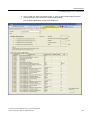
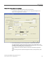
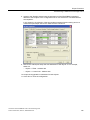
Alignment with an Active Line Module (ALM)
To perform the alignment, open the "S120_CU320" folder in S7T Config.
Double-click "Communication > Message frame configuration".
There you check and correct the order of the individual components.
To do this, select the relevant component and use the arrow buttons to move it up or down.
To align with HW Config, click "Align message frame with HW Config: Set up addresses"
and confirm the security prompt with "Yes".
The appropriate I/O addresses of the message frames are thereby entered for all
parameterized axes. The PROFIdrive message frame must be extended to read in the inputs
and outputs of the terminal board or control unit. For more information, refer to the chapter
"Diagnosing the SINAMICS configuration (Page 75)".
Connection of the SINAMICS S120 to the Technology CPU
Product Information, 09/2011, A5E00480378-04
69
Commissioning
3.4 Configuring the drive components
Alignment with a Smart Line Module (SLM)
To perform the alignment, open the message frame configuration in S7T Config
(same as for the ALM), and check and correct the order of the individual components there.
To do this, select the relevant component, and use the arrow buttons to move it up or down.
The objects must be kept in the following order:
1. Drives
2. Option modules
3. Control unit
The alignment procedure is the same as with an Active Line Module (ALM)
This concludes the configuration. You can check the topology of your
SINAMICS configuration. For more information, refer to the section
"Diagnosing the SINAMICS configuration (Page 75)".
See also
Extending a PROFIdrive message frame (Page 130)
3.4.5
Loading the configuration into the drive components
Procedure
Once the configuration in S7T Config is complete, save and compile the settings and
interconnections you have made. Now switch to online mode and load the configuration into
the SINAMICS S120.
To do so, select SINAMICS_S120. In the context menu,
select the Target Device > Download command.
Note
If an error occurs during the save and compile operation, you should check the
HW Config settings for constant bus cycle time and the DP cycle on the
PROFIBUS DP (Drive).
Connection of the SINAMICS S120 to the Technology CPU
70
Product Information, 09/2011, A5E00480378-04
Commissioning
3.4 Configuring the drive components
3.4.6
Optimizing the speed controller in the drive
Introduction
The controllers in the drive must be working optimally to ensure that systems are not
susceptible to faults.
There are tools for automatically optimizing the controller in
SINAMICS firmware version V2.5 and S7 Technology V4.1 or later.
The following requirements must be fulfilled to use automatic controller optimization:
● The drive may be moved without hitting the mechanical limits
● The drive is running in "SERVO" mode.
● The motor encoder performs the closed-loop control.
● There is an online connection to the relevant drive unit.
● The open-loop control is in STOP mode.
Connection of the SINAMICS S120 to the Technology CPU
Product Information, 09/2011, A5E00480378-04
71
Commissioning
3.4 Configuring the drive components
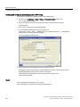
Procedure
1. Switch to online mode.
2. In the navigator, select the drive to be optimized, then switch to the
\Commissioning\Automatic controller setting sub-folder.
3. Set the T-CPU to STOP mode.
4. Obtain control priority by pressing the "Get control priority!" button in the
automatic controller setting dialog.
5. Switch on the drive by clicking "Drive ON" in the automatic controller setting dialog.
Connection of the SINAMICS S120 to the Technology CPU
72
Product Information, 09/2011, A5E00480378-04
Commissioning
3.4 Configuring the drive components
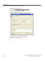
6. Carry out the four steps in automatic mode, or carry out the individual steps using the
operating buttons in the automatic controller setting dialog.
The controller optimization results will be displayed.
Connection of the SINAMICS S120 to the Technology CPU
Product Information, 09/2011, A5E00480378-04
73
Commissioning
3.4 Configuring the drive components
7. Transfer the calculated speed controller parameter values to the drive by clicking
"Accept" in the automatic controller setting dialog.
8. Switch off the drive by clicking "Drive OFF" in the automatic controller setting dialog.
9. Give up control priority by pressing the "Get control priority!" again in the
automatic controller setting.
10.Set the T-CPU back to RUN mode.
11.Start a "Copy RAM to ROM" operation for the drive you have just optimized.
12.Load the data from the drive back to the programming device.
13.Save and recompile the project.
Connection of the SINAMICS S120 to the Technology CPU
74
Product Information, 09/2011, A5E00480378-04
Commissioning
3.5 Diagnosing the SINAMICS configuration
3.5
Diagnosing the SINAMICS configuration
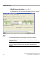
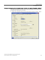
Once the configuring for the SINAMICS S120 has been completed, the topology of the
DRIVE-CLiQ wiring can be checked in online mode and the drive moved using the
SINAMICS S120 control panel.
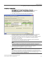
3.5.1
Checking the DRIVE-CLiQ wiring online
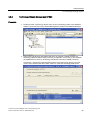
Procedure
To check the DRIVE-CliQ wiring online, follow these steps:
1. Set S7T Config to online mode.
2. Open the "S120_CU320" folder.
3. Select the "Topology" command.
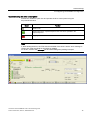
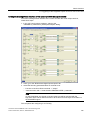
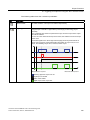
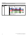
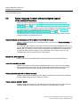
Result
The "Topology" dialog will open.
By making a comparison of the planned and the actual topology in the display windows,
any incorrect wiring of the DRIVE-CLiQ connections can be determined quickly.
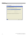
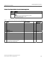
The display topology views have the following meaning:
Topology view
Planned project
Planned
Actual
Meaning
Topology of the DRIVE-CLiQ components programmed offline in
S7T Config.
Topology of the wiring of the DRIVE-CLiQ components loaded
online into the drive.
Real wiring of the DRIVE-CLiQ drive components.
Corrections in the wiring can be made by means of the hardware by replugging the
DRIVE-CLiQ connections or in the "Project set" window by dragging the components to the
correct DRIVE-CLiQ connection.
Connection of the SINAMICS S120 to the Technology CPU
Product Information, 09/2011, A5E00480378-04
75
Commissioning
3.5 Diagnosing the SINAMICS configuration
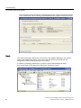
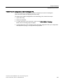
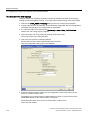
3.5.2
Drive test using the SINAMICS control panel
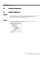
Introduction
After the successful configuring of the SINAMICS S120 drive system, the drives can be
controlled and moved in speed-controlled operation using the drive control panel in
S7T Config.
Assuming control priority
Open the "S120_CU320" folder in S7T Config.
Select the Drives > Drive_1 > Commissioning > Control Panel command.
Select there the drive that is to be tested. Transfer the control priority to S7T Config by
clicking "Get control priority".
Read the security message.
Connection of the SINAMICS S120 to the Technology CPU
76
Product Information, 09/2011, A5E00480378-04
Commissioning
3.5 Diagnosing the SINAMICS configuration
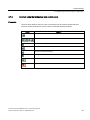
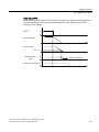
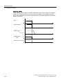
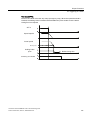
Operation using the drive control panel
Activate the "Enables" option box and operate the drive control panel using the
keys described below:
Button
Function
Enable the infeed for an Active Line Module or for a Basic Line Module using
DRIVE-CLiQ.
Starting the motion. A speed setpoint for the axis can be specified in the
Setpoint input box.
Stopping the motion.
Note
If, after starting the drive, the "The switch-on disable of the drive is active" error message is
issued, then reset the signal for the switch-on disable.
To do this, switch to the Interrupts tab and acknowledge the pending interrupts.
Connection of the SINAMICS S120 to the Technology CPU
Product Information, 09/2011, A5E00480378-04
77
Commissioning
3.6 Creating technology objects
3.6
Creating technology objects
3.6.1
Creating and configuring axes
Introduction
Once the SINAMICS S120 drive system has been configured and placed in operation, the
axes must now be created in the technology section of the Technology CPU.
This gives the CPU the access to and the control of the axes.
Procedure
1. Open the Technology folder in S7T Config and double-click on the "Insert axis"
function to add an "axis" technology object.
Connection of the SINAMICS S120 to the Technology CPU
78
Product Information, 09/2011, A5E00480378-04
Commissioning
3.6 Creating technology objects
2. Enter in the first dialog box a name for the axis and select the required axis technology.
Click on the "OK" button to confirm your entry.
Note
The axis technology can no longer be changed once it has been selected.
If a different axis technology is to be selected, the technology object must be recreated.
Connection of the SINAMICS S120 to the Technology CPU
Product Information, 09/2011, A5E00480378-04
79
Commissioning
3.6 Creating technology objects
3. Select "Linear, Electric" as the axis type used. Select "Configure units"
if needed and click "Next" to confirm the setting.
Connection of the SINAMICS S120 to the Technology CPU
80
Product Information, 09/2011, A5E00480378-04
Commissioning
3.6 Creating technology objects
4. The axis is now assigned to the drive of the SINAMICS S120. If the SINAMICS S120 is
not yet available in the list of drive devices, click the "Set up addresses" button.
A free drive of the selected drive device can be selected from the list for the assignment.
The message frame (e.g. message frame 105) required for the communication between
the Technology CPU and the drive system will be fetched automatically from the drive
configuration.
5. Select the motor type. The maximum motor speed can be set to the maximum speed of
the motor connected to the selected drive.
6. To do this, click the "Data transfer from the drive" button to ensure that the data is
consistent between the controller and drive. Click the "Next" button to accept the settings.
Connection of the SINAMICS S120 to the Technology CPU
Product Information, 09/2011, A5E00480378-04
81
Commissioning
3.6 Creating technology objects
7. Select the encoder type, the encoder mode and the measuring system to be connected to
the selected drive. Again, click the "Data transfer from the drive" button to automatically
accept the data configured in the drive.
Connection of the SINAMICS S120 to the Technology CPU
82
Product Information, 09/2011, A5E00480378-04
Commissioning
3.6 Creating technology objects
8. Enter the encoder-specific data, for example, encoder pulses per revolution and fine
resolution. Additional information on this data can be obtained in the chapter
"Encoder settings" (Page 93)".
If you have transferred the encoder data using the "Data transfer from the drive" button,
the encoder-specific data will already be preset correctly.
You can then immediately confirm the dialog with "Next".
Connection of the SINAMICS S120 to the Technology CPU
Product Information, 09/2011, A5E00480378-04
83
Commissioning
3.6 Creating technology objects
9. At the end of the configuration, you can once again check the entered data in the
overview before you click the "Finish" button to close the configuration.
Also create the technology objects for all other axes of the SINAMICS S120 drive system
and then close S7T Config.
Connection of the SINAMICS S120 to the Technology CPU
84
Product Information, 09/2011, A5E00480378-04
Commissioning
3.6 Creating technology objects
3.6.2
Technology Objects Management (TOM)
Procedure
1. Double-click the "Technology objects" entry in the "Technology" folder of the SIMATIC
station to open the Technology Objects Management (TOM) in the SIMATIC Manager.
2. The list of the technology data blocks that have not yet been created contains the
technology objects that have been previously configured in S7T Config or are available
as standard but for which no technology data blocks have been created previously.
If necessary, change the suggested DB numbers of the technology objects in the first
column of the list and click the "Create" button to create the technology data blocks.
Connection of the SINAMICS S120 to the Technology CPU
Product Information, 09/2011, A5E00480378-04
85
Commissioning
3.6 Creating technology objects
The created technology data blocks are displayed in the list of the technology data blocks
in the module folder. The Technology Objects Management program can then be closed.
Result
The created technology data blocks are now also in the SIMATIC Manager in the "Blocks"
folder of the SIMATIC 300 station. The icons of the data blocks are derived from the
designations of the technology objects in S7T Config.
In addition to technology data blocks, a number of User Defined Datatypes (UDT)
that from the basis for the technology data blocks will also be created.
Connection of the SINAMICS S120 to the Technology CPU
86
Product Information, 09/2011, A5E00480378-04
Commissioning
3.7 Diagnosing the technology configuration
3.7
Diagnosing the technology configuration
3.7.1
Overview
Introduction
The configuration of the "Axes" technology objects in S7T Config can also be checked using
the axis control panel in S7T Config. The motion commands can be specified directly for the
technology objects and thus the successful linking of the technology objects with the drives.
3.7.2
Preparations
Enabling CPU peripherals
To control the technology objects from the axis control panel, the CPU must be in STOP
mode and the I/Os must be enabled to allow the CPU outputs to be specifically influenced.
The I/Os can only be enabled via a variable table. If necessary, create a new variable table,
switch this to online mode and select the Enable PA function from the Variable menu.
In STOP mode of the CPU, you can now directly access the I/Os of the input/output modules
and the axes.
Enabling the infeed for an Active Line Module or a Basic Line Module
As of S7 Technology V3.0 SP2, the infeed can be enabled via the control panel.
Connection of the SINAMICS S120 to the Technology CPU
Product Information, 09/2011, A5E00480378-04
87
Commissioning
3.7 Diagnosing the technology configuration
Enabling the infeed for a Smart Line Module
The ready signal is used to enable a Smart Line Module without DRIVE-CLiQ interface.
As shown in the chapter "Manual configuring" (Page 39), Configuration with
Smart Line Modules (SLM)", this was connected when you configured the
Smart Line Module. Ensure that the ready signal has logical value 1 in order to enable the
Smart Line Module.
Enabling the axis using the axis control panel
To do this, open the axis control panel in S7T Config using "Technology\Axes\Axis_1\Control
panel" and select the required axis from the dropdown list box. Transfer the control priority to
the axis control panel by clicking the "Assume control priority" button and acknowledging the
message that appears by clicking the "Accept" button.
Connection of the SINAMICS S120 to the Technology CPU
88
Product Information, 09/2011, A5E00480378-04
Commissioning
3.7 Diagnosing the technology configuration
3.7.3
Axis test using the technology axis control panel
Procedure
Once the drive infeed is active, the axis control panel can be used to operate the axes.
The axis control panel buttons can be used to invoke the following functions:
Button
Function
Set axis enable.
Select the operating mode of the axis:
Speed-controlled operation
Position-controlled operation
Absolute or relative positioning
Homing
Start from the control panel the motion set for the axis.
Stop the set axis motion.
Connection of the SINAMICS S120 to the Technology CPU
Product Information, 09/2011, A5E00480378-04
89
Commissioning
3.7 Diagnosing the technology configuration
Depending on the selected operating mode of the axis, various parameters for the axis
motion can be specified in an additional input window.
Example: Positioning axis
Connection of the SINAMICS S120 to the Technology CPU
90
Product Information, 09/2011, A5E00480378-04
Commissioning
3.8 Creating the user program
3.8
Creating the user program
3.8.1
Using technology functions
The user program is used to trigger the axes in cyclic operation of the Technology CPU.
Technology functions can be used to trigger the technology objects, such as axes,
output cams, external encoders, measuring probes, etc.
The individual motions of the axes are programmed by calling the appropriate technology
function module in the S7 user program in the correct sequence.
Sample programs in the Internet
Executable sample programs with graphical user interface for the technology CPU are
available for download in the "Applications and Tools" area on the Internet
(http://support.automation.siemens.com).
3.8.2
Special considerations for the use of an Active Line Module
Special considerations
To enable an axis using the FB 401 "MC_Power", the enable for the infeed must have
already been set on the drive system.
You usually enable the Smart Line Module by means of an integral hardware contact on the
module.
Enable for the Active Line Module, Basic Line Module, and specific applications of the
Smart Line Module must be transferred to the infeed via PROFIBUS using control
information. A block is available for this purpose on the Internet
(http://support.automation.siemens.com/WW/view/en/21971603)
for integration in your user program where it carries out the enable of the infeed.
Connection of the SINAMICS S120 to the Technology CPU
Product Information, 09/2011, A5E00480378-04
91
Commissioning
3.8 Creating the user program
Connection of the SINAMICS S120 to the Technology CPU
92
Product Information, 09/2011, A5E00480378-04
Basic functions
4.1
Encoder settings
4.1.1
Encoder configuration (overview)
4
Principle
The supported encoder types depend on the device. You will find more detailed information
in the supplementary descriptions, or in the manuals for the SINAMICS S120 and the drives.
The encoder is configured in S7T Config in two stages:
1. Set the encoder type when you configure the drive.
2. Set selected dependent encoder parameters, such as number of data bits,
resolution etc. when you configure the axis.
4.1.2
Characteristic values for encoders
Encoder actual values
In the message frame between the drive and PLC, two encoder actual values are used to
transmit the encoder position - the "cyclical actual value" Gn_XIST_1
(n = 1 or 2, number of the encoder), and the "absolute actual value" Gn_XIST_2
(n = 1 or 2, number of the encoder).
Connection of the SINAMICS S120 to the Technology CPU
Product Information, 09/2011, A5E00480378-04
93
Basic functions
4.1 Encoder settings
Cyclical actual value: Gn_XIST_1
In the "cyclical actual value" Gn_XIST_1 (n = 1 or 2, number of the encoder), the incremental
change in position of the encoder is transmitted to the PLC. The drive simply evaluates the
counting pulses of the encoder, and generates the "cyclical actual value" from them.
As soon as the drive control unit is connected to the supply voltage, the value zero is always
transmitted via the "cyclical actual value".
The "cyclical actual value" Gn_XIST_1 is always filled by the drive unit, irrespective of
whether an absolute encoder or an incremental encoder is being used.
Note
The data bits of the "cyclical actual value" Gn_XIST_1 (n = 1 or 2, number of the encoder)
must correspond to the structure of the encoder actual value that is configured in
S7T Config. Otherwise, the position information transferred from the encoder to the PLC
will be incorrectly interpreted by the technology CPU.
Absolute actual value: Gn_XIST_2
Non-cyclical encoder values are transmitted in the "absolute actual value" Gn_XIST_2
(n = ...). These values must be requested by the PLC prior to transmission.
The following values may be requested by the PLC via the axis message frame:
● Absolute value of the encoder if an absolute encoder is being used.
● Synchronization position when a synchronization mark (e.g. reference mark) is overshot,
and requested synchronization function (e.g. on-the-fly homing).
● Measurement position when a measuring input on the drive is triggered,
and a measurement function is requested.
The "absolute actual value" is not described with valid values which can then be evaluated in
the PLC until the drive has executed the requested function.
Connection of the SINAMICS S120 to the Technology CPU
94
Product Information, 09/2011, A5E00480378-04
Basic functions
4.1 Encoder settings
Example:
The position value of an absolute encoder is set in the PLC as follows:
1. The PLC uses a command to request the absolute value of the encoder from the
drive unit.
2. The drive unit reads the absolute value from the encoder.
3. The absolute value of the encoder is returned by the drive unit in the
"absolute actual value" Gn_XIST_2 (n = 1 or 2, number of the encoder) to the PLC.
4. The PLC fills the position value of the axis with the reported absolute value of the
encoder.
All other position changes of the axis are now reported to the PLC via the "cyclical actual
value" Gn_XIST_1 (n = 1 or 2, number of the encoder) of the encoder.
Note
The data bits of the "absolute actual value" Gn_XIST_2 (n = 1 or 2, number of the encoder)
must correspond to the structure of the encoder actual value that was configured in
S7T Config. Otherwise, the position information transferred from the encoder to the PLC
will be incorrectly interpreted by the technology CPU.
4.1.3
Structure of the encoder actual values
Structure of the encoder actual value
The following information is contained in the encoder actual values of the
"cyclical actual value" Gn_XIST_1 (n = 1 or 2, number of the encoder), and the
"absolute actual value" Gn_XIST_2 (n = 1 or 2, number of the encoder):
● Multiturn information (only with Gn_XIST_2)
● Encoder pulse count
● Fine resolution
0XOWLWXUQ
LQIRUPDWLRQ
(QFRGHU
SXOVHFRXQW
)LQH
UHVROXWLRQ
NOTICE
The position of the data in the encoder actual value is not fixed; it depends on the values
set for the encoder pulses per revolution and the fine resolution.
Connection of the SINAMICS S120 to the Technology CPU
Product Information, 09/2011, A5E00480378-04
95
Basic functions
4.1 Encoder settings
Multiturn information (parameter 421 in the drive)
The multiturn information contains the number of full encoder revolutions.
With each complete revolution of the encoder, the multiturn information is incremented by
one. If the maximum data width of the multiturn information is achieved, the encoder actual
value is reset to zero.
Encoder pulses per revolution (parameter 408 in the drive)
The encoder pulses per revolution is the characteristic parameter of the encoder. It defines
the number of encoder tallies per revolution. For analog encoders, it specifies the number of
sine / cosine oscillations per revolution. Optical encoders have tallies which are etched on a
sheet of glass. The greater the number of encoder pulses per revolution, the higher the
resolution of the encoder.
Sometimes the encoder data gives the encoder resolution (e.g. 12-bit resolution),
rather than the number of tallies. The encoder pulses per revolution are calculated
as follows:
Encoder pulses per revolution = 2resolution
USine track
Cosine pick-off
Excitation: 2 to 10 kHz
UCosine track
Rotary
transformer
G_DA65_en_00048
Sine pick-off
Connection of the SINAMICS S120 to the Technology CPU
96
Product Information, 09/2011, A5E00480378-04
Basic functions
4.1 Encoder settings
Fine resolution (parameter 418 / Parameter 419 in the drive)
Encoders can provide much more precise information via their internal sampling mechanism
(sine / cosine oscillations, sub-sampling on a etched pane of glass). These can be evaluated
by the drive unit, and transferred to the PLC as a fine resolution.
The encoder actual values that can be transferred from the drive to the PLC are limited to
32-bit, however. If, for example, a standard multiturn encoder with a 12-bit (4096) multiturn
resolution and an 11-bit (2048) encoder resolution is used, there will be just
32-12-11 = 9 bits (512) remaining in the encoder actual value for transferring the
fine resolution.
If a greater fine resolution is to be transferred in the encoder actual value, the multiturn
resolution of the encoder actual value is reduced; although this increases the precision of the
encoder, it does reduce the encoder's absolute measuring range.
0XOWLWXUQ
LQIRUPDWLRQ
(QFRGHU
SXOVHFRXQW
)LQH
UHVROXWLRQ
With the technology CPU, the fine resolution for the cyclical actual value (Gn_XIST_1) is to
be set as a multiplication factor of the cyclical actual value. The factory setting of 11 bits is
correct for all standard Siemens motor encoders. It does not normally have to be changed.
The multiplication factor of the absolute actual value (Gn_XIST_2) is the fine resolution of the
absolute actual value. The factory setting of 9 bits is correct for all standard Siemens motor
encoders and does not have to be changed.
The multiplication factor of the absolute actual value is usually smaller than the multiplication
factor of the cyclical actual value, as there is more multiturn information to be transferred in
the absolute actual value (Gn_XIST_2).
If an incremental encoder is used, the absolute actual value (Gn_XIST_2) is structured
exactly as the cyclical actual value (Gn_XIST_1). The multiplication factor of the absolute
actual value (Gn_XIST_2) is then irrelevant.
Connection of the SINAMICS S120 to the Technology CPU
Product Information, 09/2011, A5E00480378-04
97
Basic functions
4.1 Encoder settings
Number of data bits
When you configure an axis in S7T Config, you must specify the "number of data bits" for the
encoder.
The "number of data bits" corresponds to the proportion of user data of the 32-bit wide
encoder actual value, and is calculated from the sum of the data bits for the encoder and
multiturn resolutions.
To display the position correctly, the values set in S7T Config must agree with the values
configured in the drive.
0XOWLWXUQ
LQIRUPDWLRQ
(QFRGHU
SXOVHFRXQW
)LQH
UHVROXWLRQ
Number of data bits
Note
In firmware version 4.1 or later, the values from the drive can be transferred to the axis
configuration at the press of a button in S7T Config.
Connection of the SINAMICS S120 to the Technology CPU
98
Product Information, 09/2011, A5E00480378-04
Basic functions
4.1 Encoder settings
4.1.4
Encoder types
Encoder type - incremental encoder
Incremental encoders output the value zero after the supply voltage has been interrupted.
Axes with incremental encoders must be rereferenced after each voltage interruption.
Encoder type - absolute encoder
Absolute encoders can also provide the absolute position value after the supply voltage of
the drive control unit has been interrupted. This must be requested for each encoder function
from the PLC to the drive unit.
Special features of absolute encoders
The following selection possibilities are available in the
"Axis configuration - Encoder assignment" dialog for the selection of an absolute encoder:
● Absolute value encoder:
In this case, the total number of overflows of the absolute actual value will not be saved
when the technology CPU is switched off.
At the next switch on, the actual position value will be formed only from the absolute
actual value that the converter passed to the technology CPU in Gn_XIST_2.
For a multiturn resolution of 4096 and a leadscrew pitch of 10 mm/revolution,
this always produces a value that lies between 0 m and approx. 40 m.
This setting of the absolute value encoder is normally used for encoders for rotary axes
(modulo axes). For this setting, the complete traversal area must be covered by the
absolute value encoder.
● Absolutely cyclic absolute encoder
In this case, overflows of the multiturn information will be saved in the remanent memory
area of the technology CPU on shutdown and will be used to calculate the actual position
value at the next start up.
This setting must be made if the absolute encoder with its multiturn resolution does not
cover the total traversing range of the axis, and it is possible for the multiturn information
to overflow within the traversing range. Cyclical absolute should be selected especially for
the resolver encoder structure.
Connection of the SINAMICS S120 to the Technology CPU
Product Information, 09/2011, A5E00480378-04
99
Basic functions
4.1 Encoder settings
4.1.5
Encoder mode
Different protocols are used to transfer the encoder data between the encoder and the drive.
These protocols depend on which encoder is used.
The required encoder mode can be found in the technical documentation for the encoder.
4.1.6
Setting encoder parameters in the technology
Procedure
When you configure an axis or an external encoder, you set the encoder data in the relevant
dialog fields.
1. Select the encoder type, the encoder mode, and the measuring system.
Click "Data transfer from the drive" to transfer the correct encoder data from SINAMICS.
In this way you can ensure that the data is consistent between the drive and the
technology.
2. Click "Next".
Connection of the SINAMICS S120 to the Technology CPU
100
Product Information, 09/2011, A5E00480378-04
Basic functions
4.1 Encoder settings
Enter the encoder-specific data, such as the number of encoder pulses, the number of
data bits and the multiplication factors.
Note
If the value zero has been set for the multiplication factors, the factory settings
(11-bit for Gn_XIST_1 and 9-bit for Gn_XIST_2) will be used.
Connection of the SINAMICS S120 to the Technology CPU
Product Information, 09/2011, A5E00480378-04
101
Basic functions
4.1 Encoder settings
4.1.7
Display of the encoder parameters in S7T Config
Display of the encoder parameters
To display the encoder data, open the folder "\Technology\Axes\Axis_1" for the "axis_1" in
S7T Config and double-click on "Configuration" to open the dialog box for configuration of
the axis.
Connection of the SINAMICS S120 to the Technology CPU
102
Product Information, 09/2011, A5E00480378-04
Basic functions
4.1 Encoder settings
The "Encoder configurations" area of the "Configuration" dialog box contains the encoder
settings for the axis.
List of encoder parameters to be set
A current list of the encoder parameters to be set is available for download on the Internet in
the "Applications and Tools" area at the following address:
(http://support.automation.siemens.com/WW/view/en/ 27038754)
Connection of the SINAMICS S120 to the Technology CPU
Product Information, 09/2011, A5E00480378-04
103
Basic functions
4.2 Homing
4.2
Homing
4.2.1
Homing possibilities
Introduction
The "Homing" function is used to align the actual value of an encoder with the position of the
machine after the supply power is switched on or after the replacement of the encoder.
Where as incremental encoders must be homed after each restart of the system, absolute
encoders normally only need to be homed after a replacement of the encoder or the twisting
of the spindle without encoder.
The following homing possibilities exist:
● Active homing
● Passive homing
● Direct homing
Active homing
A special traversing motion is executed for this type of homing.
Any running active motion command will be cancelled.
The following homing modes can be set in S7T Config:
● Homing with reference cam and encoder zero mark
● Homing only with reference cam
● Homing only with encoder zero mark
● Correct position value
● Correct internal axis coordinate system
Passive homing
The homing does not cause any motion of the axis in this case.
Any running motion commands will not be affected.
The following homing possibilities exist:
● Homing with reference cam and encoder zero mark
● Homing only with reference cam
● Homing with only encoder zero mark.
Connection of the SINAMICS S120 to the Technology CPU
104
Product Information, 09/2011, A5E00480378-04
Basic functions
4.2 Homing
Direct homing
The axis position will be set without taking account of the reference cam (encoder zero mark
or reference cam). If the home position is to be exactly assigned to a mechanical position,
the axis must be stationary during the action.
Correct position value
An offset value will be subtracted from the current axis position.
Any current motions and the homing will not be affected.
Correct internal axis coordinate system
An offset value will be subtracted from the current position of the base or the superimposed
coordinate system. Any current motions and the homing will not be affected.
4.2.2
Example: Active homing with homing output cam and encoder zero mark
Introduction
If in the complete travel area, the encoder has several zero marks or the passes through the
zero mark several times, a second signal will be used for the unique homing. A homing
output cam supplies this supplementary information. The homing function for the next zero
mark passage will be enabled when the homing output cam is reached.
A typical application case is an axis with a multi-pole resolver motor encoder. Only homing
with home position switches and zero marks should be considered for a multi-pole resolver.
Operational sequence
The axis searches in the specified direction for the reference point. When the BERO signal is
attained, a switch will be made from the home position approach velocity to the home
position reduced speed. After leaving the BERO, homing will be made to the next detected
zero mark of the encoder.
Connection of the SINAMICS S120 to the Technology CPU
Product Information, 09/2011, A5E00480378-04
105
Basic functions
4.2 Homing
Hardware configuration
The homing BERO is connected to a free SIMATIC peripheral input (either to an integrated
input of the Technology CPU or to a distributed input (e.g. ET 200M) on the DP(DRIVE)).
7HFKQRORJ\&38
'ULYH&/L4FRQQHFWLRQ
;
;
;
;
;
;
;
;
,QWHJUDWHG
LQSXWRXWSXWVRI
WKH7&38
;
;
;
352),%86FRQQHFWLRQ
&8
$/0
%/0
6/0
6LQJOH
0RWRU
0RGXOH
'RXEOH
0RWRU
0RGXOH
6,1$0,&66
5HIHUHQFHFDP
0RWRUZLWKPRWRUHQFRGHU
DQG]HURPDUN
Connection of the SINAMICS S120 to the Technology CPU
106
Product Information, 09/2011, A5E00480378-04
Basic functions
4.2 Homing
Setting of the integrated inputs in the Technology CPU
In the example shown here, the digital inputs integrated in the Technology CPU are to be
used to fetch the homing output cam (BERO). The hardware address of these integrated
inputs are required for the settings of the homing mode in the technology.
You set these during the configuration of the Technology CPU in HW Config.
In the shown example, the hardware address of the first integrated digital input is
byte 66 and bit 0.
Connection of the SINAMICS S120 to the Technology CPU
Product Information, 09/2011, A5E00480378-04
107
Basic functions
4.2 Homing
Setting of the homing mode in the technology
As next step, activate the "Homing" function and enter the address of the homing
output cam.
1. To activate the "Homing" function, switch in the S7T Config project navigator to the
"\Technology\Axes\Axis_2\Homing" dialog box.
2. In the "Homing" dialog box, set the homing mode to "Homing output cam and encoder
zero mark".
The "Encoder zero mark" selection box specifies where the encoder zero mark is located
relative to the homing output cam (BERO).
Connection of the SINAMICS S120 to the Technology CPU
108
Product Information, 09/2011, A5E00480378-04
Basic functions
4.2 Homing
3. The logical hardware address of the homing output cam (BERO) must be specified.
As described above, the first integrated digital input should be used in this example.
This is configured with hardware address byte 66 and bit 0.
"Start of homing procedure" specifies the approach direction (counting direction)
of the Bero
4. Enter appropriate values in the "Approach velocity", "Entry velocity", and
"Reduced velocity" input boxes.
This completes the configuring of the technological part of the homing function in
S7T Config.
Creating the S7 user program
Use the Technology Object Manager (TOM) to create a technology data block (TO-DB),
which is assigned to the homing output cam technology object. The technology data block
(TO-DB) allows the functions on the associated technology object to be executed using the
provided FBs. For the homing, use the FB403 MC_Home function block in your S7 program.
4.2.3
Example: Active homing using only an external zero mark
Introduction
An external zero mark (Bero) should be used for homing the axis. This requires that one of
the fast integrated digital inputs of the SINAMICS S120 is used. Special configuration steps
must be carried out for this, and these are described below.
Operational sequence
The position is accepted when one of the defined BERO edges is passed.
Connection of the SINAMICS S120 to the Technology CPU
Product Information, 09/2011, A5E00480378-04
109
Basic functions
4.2 Homing
Hardware configuration
A typical application example is an encoder without zero mark evaluation. An external zero
mark (Bero) is used in place of the encoder zero mark. To ensure short response times,
it is read indirectly via the digital inputs of the CU320.
'ULYH&/L4FRQQHFWLRQ
;
;
;
&8GLJLWDO
LQSXWRXWSXWV
;
;
;
;
;
;
;
;
7HFKQRORJ\&38
352),%86FRQQHFWLRQ
&8
$/0
%/0
6/0
6LQJOH
0RWRU
0RGXOH
'RXEOH
0RWRU
0RGXOH
6,1$0,&66
([WHUQDO]HUR
PDUNHU
0RWRUZLWKPRWRUHQFRGHU
Connection of the SINAMICS S120 to the Technology CPU
110
Product Information, 09/2011, A5E00480378-04
Basic functions
4.2 Homing
Assignment of the equivalent zero mark signal to the digital input of the SINAMICS
For homing to an external zero mark with axes on the PROFIBUS, the external zero mark
must be configured as digital input on the drive. This requires that the configuration of the
drive specifies which internal digital input of the CU320 is to be used to fetch the equivalent
zero mark signal.
Only the fast digital inputs can be used as internal digital inputs of the CU320 for fetching the
equivalent zero mark signal:
DI/DO 9
X122.8
DI/DO 10
X122.10
DI/DO 11
X122.11
DI/DO 13
X132.8
DI/DO 14
X132.10
DI/DO 15
X132.11
To parameterize the CU 320 input for fetching the equivalent zero mark signal, switch in the
S7T Config project navigator to the appropriate drive. In the example shown here, to the
dialog box: "\Technology\SINAMICS_S120\Drives\SERVO_02. Start the expert list with a
right mouse click on the drive and selecting Expert > Expert List in the submenu. Select the
"p495 [0] equivalent zero mark input terminal encoder 1" parameter in the expert list and
interconnect the parameter with the DI/DO 9 (X122.8) (1) input.
A different equivalent encoder can also be selected for the assignment of the zero mark
input.
P495[0]
Encoder 1
P495[1]
Encoder 2
P495[2]
Encoder 3
Connection of the SINAMICS S120 to the Technology CPU
Product Information, 09/2011, A5E00480378-04
111
Basic functions
4.2 Homing
Inverting the selected digital input of the SINAMICS
A general condition in conjunction with SINAMICS governs the homing only with an external
zero mark. Only negative edges are permitted for the positive travel direction and only
positive edges are permitted for the negative travel direction, this means that the same cam
side is always used. This means that your construction circumstances may require that the
BERO signal needs to be inverted.
To invert the Bero signal, switch in the S7T Config project navigator to the dialog box:
"\Technology\SINAMICS_S120\Control_Unit. Mark the "Control_Unit" entry and select
Expert list in the shortcut menu in order to open the expert list. Parameter "p490.9 DI/DO 9
(X122.8)" allows you to invert the digital input DI/DO 9.
A separate parameter is provided for inverting each digital input that can be used to fetch the
external zero mark. The following table contains the correct parameters for the selected
digital input:
P490.9
DI/DO 9
X122.8
P490.10
DI/DO 10
X122.10
P490.11
DI/DO 11
X122.11
P490.13
DI/DO 13
X132.8
P490.14
DI/DO 14
X132.10
P490.15
DI/DO 15
X132.11
This completes the assignment of the internal digital input of the CU320 to the equivalent
zero mark signal in the SINAMICS.
Connection of the SINAMICS S120 to the Technology CPU
112
Product Information, 09/2011, A5E00480378-04
Basic functions
4.2 Homing
Setting of the homing mode in the technology
The next step is to enable the "Homing" function in the technology.
1. To activate the "Homing" function, switch in the S7T Config project navigator to the
dialog: "\Technology\Axes\Axis_2\Homing".
2. In the "Homing" dialog box, set the "Homing mode" to "External zero mark only".
The "Signal transition" selection boxes specify whether a rising or falling edge is to be
evaluated to detect the Bero signal. The direction of the signal transition can be reversed
by inverting the selected digital input as described above.
"On the external zero mark side" specifies on which side of the Bero the approach is
made.
"Start of homing procedure" specifies the approach direction (counting direction) of the
Bero
Connection of the SINAMICS S120 to the Technology CPU
Product Information, 09/2011, A5E00480378-04
113
Basic functions
4.2 Homing
3. Enter appropriate values in the "Approach velocity", "Entry velocity", and
"Reduced velocity" input boxes.
Note
Note that only negative edges are permitted for the positive travel direction, and only
positive edges are permitted for the negative travel direction, which means that the same
cam side is always used.
This completes the configuring of the technological part of the homing function in
S7T Config.
Creating the S7 user program
Use the Technology Object Manager (TOM) to create a technology data block (TO-DB),
which is assigned to the homing output cam technology object. The technology data block
(TO-DB) allows the functions on the associated technology object to be executed using the
provided FBs. For the homing, use the FB403 MC_Home function block in your S7 program.
4.2.4
Example for active homing with one of the external zero marks mirrored
on the T-CPU.
Introduction
An external zero mark (Bero) should be used for homing the axis. It is therefore necessary to
use one of the fast integrated digital inputs of the SINAMICS S120. In addition to the
example of active homing with external zero mark only, the zero mark signal is also read into
the Technology CPU.
Operational sequence
The position is accepted when one of the defined BERO edges is passed. In contrast to
active homing with external zero mark only, the Technology CPU also evaluates the status of
the BERO (assigned / unassigned). This allows the direction to be reversed can during
homing in addition to the selected homing settings.
Connection of the SINAMICS S120 to the Technology CPU
114
Product Information, 09/2011, A5E00480378-04
Basic functions
4.2 Homing
Hardware configuration
A typical application example is an encoder without zero mark evaluation. An external zero
mark (Bero) is used in place of the encoder zero mark. To ensure short response times, it is
read indirectly via the digital inputs of the CU320. The same signal is also evaluated via an
integrated input on the Technology CPU.
7HFKQRORJ\&38
LQWHJUDWHG
LQSXWRXWSXWV
RI7&38
'ULYH&/L4FRQQHFWLRQ
X203
X202
X101
X200
X201
X200
X132
X100
X122
'LJLWDO
LQSXWRXWSXWV
&8
X202
X201
PROFIBUS connection
CU320
ALM
BLM
SLM
Single
Motor
Module
Double
Motor
Module
6,1$0,&66
Reference cam
M
0RWRUZLWKPRWRUHQFRGHU
Allocating the zero mark substitute signal to the digital input of the SINAMICS and inverting the
selected digital inputs of the SINAMICS
Assign the digital input of SINAMICS as a zero mark substitute signal as described in
Section 4.2.3 Example of active homing with external zero mark only.
If necessary, invert the input that was used to detect the zero mark substitute signal as
described in section 4.2.3 Example of active homing with external zero mark only.
Connection of the SINAMICS S120 to the Technology CPU
Product Information, 09/2011, A5E00480378-04
115
Basic functions
4.2 Homing
Setting of the homing mode in the technology
The next step is to enable the "Homing" function in the technology.
1. To activate the "Homing" function, in the S7T Config project navigator switch to the
dialog: "\Technology\Axes\Axis_2\Homing".
2. In the "Homing" dialog box, set the "Homing mode" to "External zero mark only".
3. Select "Yes" from the "Ext. zero mark signal from drive available" selection box.
The "Signal transition" selection fields specify whether a falling or rising edge is to be
used to recognize the Bero signal.
"On the external zero mark side" indicates at which side of the Bero the edge will be
evaluated for homing.
"Homing procedure" specifies the approach direction (counting direction) of the Bero
Connection of the SINAMICS S120 to the Technology CPU
116
Product Information, 09/2011, A5E00480378-04
Basic functions
4.2 Homing
4. In the "Ext. zero mark input" box, enter the address of the integrated inputs of the
Technology CPU from HW Config, for example PI66.0.
5. Enter meaningful values in the "Approach velocity", "Entry velocity",
and "Reduced velocity" input boxes.
Note
Note that only negative edges are permitted for the positive travel direction, and only
positive edges are permitted for the negative travel direction, which means that the same
cam side is always used. In the dialog box for the "Homing" function, select the
"Data transfer from the drive" button to preassign the input fields with the data set for
SINAMICS. If you then change the settings, the necessary settings in SINAMICS will be
displayed in an information box.
This completes the configuration of the technological part of the homing function in
S7T Config.
Creating the S7 user program
Use the Technology Object Manager (TOM) to create a technology data block (TO-DB),
which is assigned to the homing output cam technology object. The technology data block
(TO-DB) allows the functions on the associated technology object to be executed using the
provided FBs. For the homing, use the FB403 MC_Home function block in your S7 program.
4.2.5
Example: Active homing using only an encoder zero mark
Introduction
The simplest form of homing is the homing only with encoder zero mark. It is used,
for example, for axes whose encoder has only one zero mark in the complete travel area of
the axis. This homing command causes the axis to travel to the zero mark. Once the axis
detects the zero mark, the home position offset is applied at homing entry velocity.
The axis position now has the value specified in the home position coordinate.
Operational sequence
No BERO signal is required. The position is accepted at the next zero mark of the encoder.
Connection of the SINAMICS S120 to the Technology CPU
Product Information, 09/2011, A5E00480378-04
117
Basic functions
4.2 Homing
Hardware configuration
A motor encoder with zero mark is connected to the SINAMICS S120. The evaluation can be
made using the zero mark signal of the encoder, an additional homing output cam (Bero) is
not required.
7HFKQRORJ\&38
'ULYH&/L4FRQQHFWLRQ
;
;
;
;
;
;
;
;
;
;
;
352),%86FRQQHFWLRQ
&8
$/0
%/0
6/0
6LQJOH
0RWRU
0RGXOH
'RXEOH
0RWRU
0RGXOH
6,1$0,&66
0RWRUZLWKPRWRUHQFRGHU
DQG]HURPDUN
Connection of the SINAMICS S120 to the Technology CPU
118
Product Information, 09/2011, A5E00480378-04
Basic functions
4.2 Homing
Setting of the homing mode in the technology
Because the input signal for the homing is part of the information transferred from the motor
encoder, no further steps are required in the configuration of the drive.
You can start immediately by activating the "Homing" function in the technology.
1. To activate the "Homing" function, switch in the S7T Config project navigator to the
dialog box: "\Technology\Axes\Axis_2\Homing".
2. In the "Homing" dialog box, set the "Homing mode" to "Encoder zero mark only".
"Start of homing procedure" specifies the approach direction (counting direction)
of the encoder zero mark.
3. Enter meaningful values in the "Approach velocity", "Entry velocity",
and "Reduced velocity" input boxes.
This completes the configuring of the technological part of the homing function in
S7T Config.
Connection of the SINAMICS S120 to the Technology CPU
Product Information, 09/2011, A5E00480378-04
119
Basic functions
4.2 Homing
Creating the S7 user program
Use the Technology Object Manager (TOM) to create a technology data block (TO-DB)
assigned to the homing output cam technology object. The technology data block (TO-DB)
allows the functions on the associated technology object to be executed using the provided
FBs. For the homing, use the FB403 MC_Home function block in your S7 program.
4.2.6
Absolute encoder adjustment with the control panel
Introduction
If, because of a defect, an absolute encoder calibration must be performed if an absolute
encoder must be replaced or the drive spindle without encoder has been twisted.
This can be performed using the "MC_Home" command from the S7 user program or
from the control panel.
The following section describes how an absolute encoder adjustment can be performed from
the S7T Config control panel.
Procedure
1. Click the "Control panel" button in the "\Technology\Axes\Axis_1\Control panel"
directory of the project navigator to open the control panel in S7T Config.
2. Enable the PA process image of the CPU315T-2 DP / CPU317T-2 DP.
For the example, select "Axis_1" and click the "Assume control priority" button
to pass the control priority to the control panel.
and use "Position absolute/relative"
3. Enable the axis
encoder position 0.0 mm.
to move it to the absolute
4. Then click the
button to move the axis speed-controlled at slow speed until the zero
position of the system is reached exactly.
5. Click the "Home axis"
function in the control panel.
Connection of the SINAMICS S120 to the Technology CPU
120
Product Information, 09/2011, A5E00480378-04
Basic functions
4.2 Homing
6. In the "Parameters" tab, set the "Absolute encoder adjustment" homing mode in the
selection window.
7. In the "Options" tab, enter the absolute value encoder offset
(usually the negative, current actual value) in the "Home position coordinate" input box.
Connection of the SINAMICS S120 to the Technology CPU
Product Information, 09/2011, A5E00480378-04
121
Basic functions
4.3 Triggering of the integrated outputs of the CU 320 Control Unit
8. Press the
button to start the absolute encoder calibration.
The actual position value will be corrected with the entered offset.
The displayed position of the "Axis_1" axis is now 0.0 mm.
9. Save in the project the data that has been entered online.
4.3
Triggering of the integrated outputs of the CU 320 Control Unit
4.3.1
Example: Triggering an output cam on the integrated output of the CU 320
Introduction
This section describes how you trigger the integrated outputs of the CU 320.
The following steps are required:
1. Extending a PROFIdrive message frame
2. Creating an output cam
3. Link message frame interface of the control unit with the actual output terminal
4. Create S7 user program
Extension of the PROFIdrive message frame
The "Extending a message frame by creating additional components (Page 131)" chapter
describes how you need to extend the PROFIdrive message frame to make the integrated
outputs of the CU320 usable for the Technology CPU. Extend the PROFIdrive message
frame as described in that section.
Connection of the SINAMICS S120 to the Technology CPU
122
Product Information, 09/2011, A5E00480378-04
Basic functions
4.3 Triggering of the integrated outputs of the CU 320 Control Unit
Creating an output cam
To create a cam switch, follow these steps:
1. In the project navigator of S7T Config, switch to the
"\Technology\Axes\Axis_1\Output_Cam" dialog and double-click on "Insert output cam".
2. In the "Insert output cam" dialog, you can, for example, enter a name for this output cam.
3. Click "OK" to accept the settings.
Connection of the SINAMICS S120 to the Technology CPU
Product Information, 09/2011, A5E00480378-04
123
Basic functions
4.3 Triggering of the integrated outputs of the CU 320 Control Unit
4. To set the parameters for the output cam, switch to the
"\Technology\Axes\Axis_1\Output_Cam\Output_Cam_1" dialog in the S7T Config
project navigator.
5. Select the "Activate output" check box.
6. Enter "Hardware address 300" and "Bit number 0" from the
HW Config hardware configuration.
Result
This completes the configuring of the output cam.
Connection of the SINAMICS S120 to the Technology CPU
124
Product Information, 09/2011, A5E00480378-04
Basic functions
4.3 Triggering of the integrated outputs of the CU 320 Control Unit
Linking the message frame interface of the control unit with the output terminal
To link the message frame interface of the control unit with the actual output terminal,
follow these steps:
1. In the S7T Config project navigator, switch to the
"\SINAMICS_S120\Control_Unit\Inputs/Outputs" dialog.
2. There, go to the "Bidirectional digital inputs/outputs" tab.
3. Select the following parameterization for terminal X122:
– Function of the X122 DI/O 8 terminal -> "output"
– "Interconnection with -> r2090 bit 8 BO PROFIBUS PZD 1 parameter"
Note
On the PROFIBUS, the signals of the low-order byte will be switched with the
high-order byte. The bit interconnection to bit 8 comes from the byte-word rotation in
the PROFIBUS signal.
This completes the configuring in S7T Config.
Connection of the SINAMICS S120 to the Technology CPU
Product Information, 09/2011, A5E00480378-04
125
Basic functions
4.3 Triggering of the integrated outputs of the CU 320 Control Unit
Creating the S7 user program
Use the Technology Object Manager (TOM) to create a technology data block (TO-DB),
which is assigned to the homing output cam technology object. The technology data block
(TO-DB) allows the functions on the associated technology object to be executed using the
provided FBs.
For the output cam, use the FB 430 MC_CamSwitch function block in your S7 program.
Connection of the SINAMICS S120 to the Technology CPU
126
Product Information, 09/2011, A5E00480378-04
5
Expert Functions
5.1
PROFIdrive message frame
5.1.1
Message frame types
Selection help for the PROFIdrive message frames
By default, the SINAMICS S120 is connected to the Technology CPU via PROFIBUS DP
(DRIVE). Depending on the desired axis functionality, this connection can be made using
various device-specific message frames. The following selection table shows the properties
of the individual message types.
Sign-oflife monitoring
(SoLmon)
1.
Encoder
Speed-controlled
axis
X
Position axis /
following axis
X
X
X
X
X
X
X
X
X
X
X
X
X
X
X
X
2.
Encoder
Dynamic Servo
Control
(DSC)
Torque
reduction
(Mred)
Required
message frame
2
3
X
X
4
X
5
X
6
X
X
X
102
X
103
X
X
105
X
X
106
Note
Message frame types < 100 are standard message frames whose structure is standardized
by the PROFIdrive profile V3.
The message frame types > 100 are manufacturer-specific message frames.
Structure of the PROFIdrive message frames
If special functions of the drive are to be used or supported, the use of special PROFIdrive
message frames may be required.
The following figure shows which data are transferred with each message frame type and
consequently which functions of the drive can be supported.
Connection of the SINAMICS S120 to the Technology CPU
Product Information, 09/2011, A5E00480378-04
127
Expert Functions
5.1 PROFIdrive message frame
3='
3='
3='
3='
3='
3='
3='
3='
3='
7(/B
6HW
67:
7(/B
$FWXDO
=6:
7(/B
6HW
67:
162//B%
67:
7(/B
$FWXDO
=6:
1,67B%
=6:
7(/B
6HW
67:
162//B%
67:
*B
67:
7(/B
$FWXDO
=6:
1,67B%
=6:
*B
=6:
7(/B
6HW
67:
162//B%
67:
*B
67:
7(/B
$FWXDO
=6:
1,67B%
=6:
*B
=6:
HJ
*B;,67
HJ
*B;,67
7(/B
6HW
67:
162//B%
67:
*B
67:
;(55
.3&
7(/B
$FWXDO
=6:
1,67B%
=6:
*B
=6:
HJ
*B;,67
HJ
*B;,67
7(/B
6HW
67:
162//B%
67:
*B
67:
7(/B
$FWXDO
=6:
1,67B%
=6:
*B
=6:
7(/
6HW
67:
162//B%
67:
0B5
HG
7(/
$FWXDO
=6:
1,67B%
7(/
6HW
67:
162//B%
7(/
$FWXDO
=6:
1,67B%
7(/
6HW
67:
162//B%
7(/
$FWXDO
=6:
1,67B%
7(/
6HW
67:
162//B%
7(/
$FWXDO
=6:
1,67B%
7(/
6HW
67:
162//B%
7(/
$FWXDO
=6:
1,67B%
3='
3='
3='
3='
3='
3='
3='
3='
3='
3='
162
//B$
1,67
B$
HJ
*B;,67
*B
67:
*B
67:
0B5
HG
0B5
HG
*B
67:
0B5
HG
*B
67:
=6: 0HVV *B
:
=6:
67:
0B5
HG
*B
67:
=6: 0HVV *B
:
=6:
STW
Control word
NSOLL
M_Red
HJ
*B;,67
HJ
*B;,67
HJ
*B;,67
HJ
*B;,67
.3&
HJ
*B;,67
HJ
*B;,67
*B
=6:
HJ
*B;,67
*B
67:
HJ
*B;,67
HJ
*B;,67
;(55
.3&
HJ
*B;,67
HJ
*B;,67
*B
67:
=6: 0HVV *B
:
=6:
67:
*B
=6:
*B
67:
=6: 0HVV *B
:
=6:
67:
;(55
HJ
*B;,67
=6: 0HVV *B
:
=6:
67:
HJ
*B;,67
*B
67:
;(55
HJ
*B;,67
*B
67:
HJ
*B;,67
HJ
*B;,67
HJ
*B;,67
HJ
*B;,67
HJ
*B;,67
HJ
*B;,67
.3&
HJ
*B;,67
;(55
HJ
*B;,67
*B
=6:
*B
=6:
.3&
HJ
*B;,67
*B
=6:
ZSW
Status word
Set speed
NIST
Actual speed
Torque derating
MeldW
Message word
$$B $$B72 $$B $$B
/2$' 548( 32:(5 &855
XERR
System deviation (for DSC)
G1_XIST1
Cyclic actual value (incremental encoder)
KPC
Position controller gain
(for DSC)
G1_XIST2
Absolute actual value (absolute encoder)
AA_LOAD
Current load
(parameter r0081)
AA_TORQUE
Current torque
(parameter r0079)
AA_POWER
Current power (parameter r0082)
AA_CURR
Current motor current
(parameter r0078)
Connection of the SINAMICS S120 to the Technology CPU
128
Product Information, 09/2011, A5E00480378-04
Expert Functions
5.1 PROFIdrive message frame
5.1.2
Example: telegram 105
Structure
Telegram 105 contains the following data, where the first row of the table represents the
setpoint transfer from the controller to the drive and the second row represents the actual
value transfer from the drive to the controller.
7HOHJU
3='
67:
3ODQQHG $FWXDO
=6:
3='
3='
3='
3='
3='
3='
3='
3='
3='
162//B%
67:
0B
5HG
*B
67:
;(55
.3&
1,67B%
=6:
0VJ
:
*B
=6:
HJ
*B;,67
HJ
*B;,67
3='
3='
3='
3='
3='
3='
The individual data items have the following meaning:
STW
Control word
ZSW
Status word
NSOLL
M_Red
Set speed
NIST
Actual speed
Torque derating
MeldW
Message word
XERR
System deviation (for DSC)
G1_XIST1
Cyclical actual value (incremental
encoder)
KPC
Position controller gain (for
DSC)
G1_XIST2
Absolute actual value (absolute
encoder)
The PZD 11 to PZD 16 data ranges are not used for telegram 105.
Connection of the SINAMICS S120 to the Technology CPU
Product Information, 09/2011, A5E00480378-04
129
Expert Functions
5.2 Extending a PROFIdrive message frame
5.2
Extending a PROFIdrive message frame
5.2.1
Address areas
Introduction
The message frame types described in the "PROFIdrive message frame (Page 127)"
chapter are used to transfer the drive data.
Additional PROFIdrive message frames are available to establish a connection with the
distributed input/outputs on PROFIBUS DP (DRIVE), with integrated inputs/outputs on the
control unit, or with extensions on the Drive-CLiQ.
The PROFIdrive message frames depend on the type and the function of the system used.
The number of the data words used depends on the number of data items to be transferred.
The transferred data can be used in two address areas of the Technology CPU that are
assigned as follows:
Address area 0 - 63
The data can be used directly in the PLC user program. The MC_ReadPeriphery or
MC_WritePeriphery technology function is used to read or write the data, respectively.
This address area is used for the data exchange with the distributed I/Os on the isochronous
PROFIBUS DP (DRIVE) or for reading and writing the drive parameters in cyclical operation.
Technology objects cannot access this data.
Address area >= 64
The data is used by the technology objects. This data is read and written by means of the
connection of the parameters to the PROFIBUS interface.
This address area can be used, for example, to realize the following functions:
● Querying a hardware limit switch at the integrated inputs/outputs
● Querying a hardware limit switch at the isynchronous peripherals
● Triggering of outputs that can be used as output cam outputs
Connection of the SINAMICS S120 to the Technology CPU
130
Product Information, 09/2011, A5E00480378-04
Expert Functions
5.2 Extending a PROFIdrive message frame
5.2.2
Extending a message frame by creating additional components
Introduction
For example, to make the integrated digital input/outputs of the SINAMICS S120 available to
the Technology CPU, the input information must be transferred via the PROFIBUS DP
(DRIVE). This requires the creation of an additional PROFIdrive message frame for the
control unit.
Procedure
To create an additional PROFIdrive message frame for the control unit, follow these steps:
1. Open the message frame configuration of SINAMICS S120.
2. Perform an alignment with HW Config by clicking "Align message frame with HW Config:
Set up addresses".
3. Ensure that no I/O addresses have been entered in the "Control Unit" line.
4. Note for the subsequent steps the object number of the objects that have not yet been
connected with the PROFIBUS. This sequence and also the position are required for the
address assignment in HW Config.
In our example, the following object numbers must be noted:
– Object 3 - TB30
– Object 4 - Control Unit
Note
The "Configuration" window must be closed after the alignment. Otherwise
subsequent changes in the hardware configuration will not be considered and may be
discarded.
Connection of the SINAMICS S120 to the Technology CPU
Product Information, 09/2011, A5E00480378-04
131
Expert Functions
5.2 Extending a PROFIdrive message frame
5. To assign the integrated input/outputs to the control unit input/output addresses,
switch to the HW Config hardware configuration.
Connection of the SINAMICS S120 to the Technology CPU
132
Product Information, 09/2011, A5E00480378-04
Expert Functions
5.2 Extending a PROFIdrive message frame
6. Open the object properties of the SINAMICS S120 there and click the "Activate..."
button in the "Configuration" tab.
Connection of the SINAMICS S120 to the Technology CPU
Product Information, 09/2011, A5E00480378-04
133
Expert Functions
5.2 Extending a PROFIdrive message frame
7. Select a PROFIBUS standard message frame from the list for the address assignment in
the object rows.
Select the following message frames:
– Object 3 - TB30 - Standard message frame 1 PZD 2/2
– Object 4 - Control Unit - Standard message frame 1 PZD 2/2
Note
Telegrams must be entered without any gaps from top to bottom for all objects
contained in the object list. Only objects at the end of the list need not have any
assigned message frame.
Because object 4 (control unit) is required for example, this means that a message
frame must also be entered for the object 3 (TB30), even when it is not necessary for
our function.
Connection of the SINAMICS S120 to the Technology CPU
134
Product Information, 09/2011, A5E00480378-04
Expert Functions
5.2 Extending a PROFIdrive message frame
8. Switch to the "Details" tab and note the assignment of the PROFIBUS input/output
addresses. Each object of the configuration has its own area that is concluded with an
axis separator.
In this example, the selection of the two standard message frames starting at slot 10
creates the input/output area for the TB30 and the control unit.
9. Note for the subsequent steps the start addresses of the objects. In our example,
these are:
– Object 3 - TB30 - Address 296
– Object 4 - Control Unit - Address 300
10.Accept the suggested I/O addresses for both objects.
11.Click "OK" to close the configuration.
Connection of the SINAMICS S120 to the Technology CPU
Product Information, 09/2011, A5E00480378-04
135
Expert Functions
5.2 Extending a PROFIdrive message frame
12.Close the object properties of the SINAMICS S120 and check whether the newly added
slots are listed in the address area of the SINAMICS S120.
13.Then save and compile the HW Config hardware configuration.
Connection of the SINAMICS S120 to the Technology CPU
136
Product Information, 09/2011, A5E00480378-04
Expert Functions
5.2 Extending a PROFIdrive message frame
14.Switch to S7T Config and open the "Message frame configuration" of SINAMICS S120.
Note
If the window was still open, you need to close and reopen it.
15.Click "Align message frame with HW Config: Set up addresses" to complete the new
message frame configuration.
Result
The extension of the PROFIdrive message frame for the integrated inputs/outputs
is now complete.
Connection of the SINAMICS S120 to the Technology CPU
Product Information, 09/2011, A5E00480378-04
137
Expert Functions
5.2 Extending a PROFIdrive message frame
5.2.3
Extending the PROFIdrive message frame in S7T Config
In S7 Technology V4.1 and higher, there is an option to extend message frames directly
in the SINAMICS message frame configuration in S7T Config.
Procedure
1. In S7T Config, open the message frame configuration of SINAMICS S120.
2. Select the drive object.
3. Click "Adapt message frame configuration" and then select "Add message frame
extension".
4. Click "Interconnections/Diagnostics" to open the message frame configuration of the drive
object. The individual control and status words of the utilized message frame are
displayed there.
5. Clear the "Suppress inactive interconnections" option to display the added words of the
message frame extension. These are designated as "user-defined".
6. Change the desired message frame properties and close the message frame
configuration.
7. Click "Align message frame with HW Config: Set up addresses" to perform alignment with
HW Config.
8. Choose "Save and compile" to activate the changes in the S7T Config project.
Connection of the SINAMICS S120 to the Technology CPU
138
Product Information, 09/2011, A5E00480378-04
Expert Functions
5.2 Extending a PROFIdrive message frame
5.2.4
Extending an existing PROFIBUS message frame for the drive
Introduction
The previous section showed you how to extend the PROFIdrive communication between
SINAMICS S120 and the Technology CPU with complete message frames to use additional
components.
In addition, the message frames for the previously configured components
(drives, technology modules, etc.) can be extended. This allows, for example,
drive parameters in the PROFIBUS message frame to be interconnected to permit their
value to be fetched cyclically by other PROFIBUS nodes (e.g. Technology CPU).
Procedure
To extend the standard message frame 105 for drive_1 to include an actual value, follow
these steps:
1. In S7T Config, open the message frame configuration of SINAMICS S120.
2. Click "Align message frame with HW Config: Set up addresses".
Check that the Siemens message frame 105 is entered for the "Drive_1" entry.
Note
After the alignment, you will have to close the "Message frame configuration" dialog.
Otherwise subsequent changes in the hardware configuration will not be considered
and may be discarded.
Connection of the SINAMICS S120 to the Technology CPU
Product Information, 09/2011, A5E00480378-04
139
Expert Functions
5.2 Extending a PROFIdrive message frame
3. Open HW Config.
4. Open the object properties for SINAMICS S120 and click "Activate" on the
"Configuration" tab.
5. Open the "Details" tab and note the assignment of the PROFIBUS I/O addresses.
Each object of the configuration has its own area that is ended with an axis disconnector.
6. To extend a message frame, an additional setpoint or actual value slot must be inserted
in front of an axis separator. This slot will be interconnected later with a parameter in
S7T Config.
Connection of the SINAMICS S120 to the Technology CPU
140
Product Information, 09/2011, A5E00480378-04
Expert Functions
5.2 Extending a PROFIdrive message frame
7. Insert a new slot by selecting row "6", for example, and then clicking "Insert slot".
To specify a new actual value slot with a length of two words on PROFIBUS address 10,
fill in the columns as follows:
– I/O address 10
– Length 2
Connection of the SINAMICS S120 to the Technology CPU
Product Information, 09/2011, A5E00480378-04
141
Expert Functions
5.2 Extending a PROFIdrive message frame
8. Switch to the "Configuration" tab.
9. Check whether the message frame type for object 1 has been changed to "user-defined".
10.Confirm your object properties changes with "OK".
Connection of the SINAMICS S120 to the Technology CPU
142
Product Information, 09/2011, A5E00480378-04
Expert Functions
5.2 Extending a PROFIdrive message frame
11.Check whether the newly inserted slot is listed in the address area of SINAMICS S120.
12.Save and compile the hardware configuration.
Connection of the SINAMICS S120 to the Technology CPU
Product Information, 09/2011, A5E00480378-04
143
Expert Functions
5.2 Extending a PROFIdrive message frame
13.Open the "Message frame configuration" in the S7T Config project navigator.
Note
If the window was still open, you need to close and reopen it.
14.Check whether the address setting from HW Config was accepted.
15.Click "Align message frame with HW Config: Set up addresses" to complete the message
frame extension.
Connection of the SINAMICS S120 to the Technology CPU
144
Product Information, 09/2011, A5E00480378-04
Expert Functions
5.3 Disabling the PROFIBUS Sign-of-Life Monitoring
5.3
Disabling the PROFIBUS Sign-of-Life Monitoring
Principle
The PROFIBUS connection between the technology CPU and the SINAMICS S120 is
monitored using a sign of life. The sign-of-life monitoring is selected automatically when the
axis is created and should always be active during operation.
For diagnostic purposes, the sign-of-life monitoring can be disabled temporarily during the
commissioning.
The parameters for the sign-of-life monitoring can be selected/deselected on the Axis
technology object with "Expert list > Configuration data" or on the drive using the "p0925"
parameter.
To do this, mark "Axis_1" and select the Expert list menu command in the context menu.
Switch in the expert list to the "Configuration data" tab and to the
"\TypeOfAxis\NumberOfEncoders\Encoder_1\DriverInfo\lifeSignCheck" dialog there.
Alternatively, you can also select the Expert list > p0925 menu command in the "Drive_1"
context menu.
Sign-of-life monitoring
\DriverInfo \lifeSignCheck
p0925
On
Yes
1
Off
No
65535
Connection of the SINAMICS S120 to the Technology CPU
Product Information, 09/2011, A5E00480378-04
145
Expert Functions
5.4 Activating a Second Encoder
5.4
Activating a Second Encoder
5.4.1
Using a Second Encoder
Introduction
A second encoder is required, for example, when the position detection does not supply
sufficient accuracy for the motor encoder or must be synchronized to external motions.
Second encoder as actual position value
For some mechanical constructions, the motor encoder cannot be used as an exact actual
position value on the system.
For such a construction, a gearbox with large play or slip is located between the motor and
the drive spindle. The motor encoder in such a case does not supply the actual position
value with sufficient accuracy.
Also the specification or the use of the slip in the parameterization of the axis in the
S7T Config project navigator for the Backlash Compensation parameter in the
"Technology\Axes\Axis_1\Mechanics" directory does not suffice to ensure an exact
position detection.
In such a case, a second encoder is mounted on the drive spindle and defined as
actual position value.
①
②
③
④
Motor encoder
Gearbox
Drive spindle
Motor encoder
Connection of the SINAMICS S120 to the Technology CPU
146
Product Information, 09/2011, A5E00480378-04
Expert Functions
5.4 Activating a Second Encoder
Second encoder as master value for synchronism functions
In a system, two independently controlled drives are to be synchronized using a gearbox or
curve synchronization.
In this case, for example, the first drive, controlled by an external drive system, transports a
wooden beam, a plastic pipe, etc.
The second drive, controlled by the technology CPU and a SINAMICS S120, moves a flying
saw to cut the material synchronous to the material transport.
A measuring roller mounted on the material transport records the traversed path and the
speed of the material. The measuring roller is connected to an external encoder that is
connected to the SINAMICS S120.
①
②
③
Measuring roller
External encoder
Drive for synchronous motion
Connection of the SINAMICS S120 to the Technology CPU
Product Information, 09/2011, A5E00480378-04
147
Expert Functions
5.4 Activating a Second Encoder
5.4.2
Connecting a second encoder in SINAMICS
Introduction
Prepare your project as described in the "Commissioning (Page 15)" chapter of this
product information so that an appropriate HW Config hardware configuration and a
NetPro network configuration are present.
The steps that deviate from the "Commissioning" chapter start with the creation of the drive
and the selection of the encoder. These steps are described in the following section.
Procedure
1. Start manual configuration of the drive and open the "Encoder 2" tab in the
"Configuration" dialog.
2. Click "Encoder data" to specify the second encoder, which in our example is connected to
the drive spindle.
Connection of the SINAMICS S120 to the Technology CPU
148
Product Information, 09/2011, A5E00480378-04
Expert Functions
5.4 Activating a Second Encoder
3. Select the properties of the connected encoder in the "Encoder data" dialog box.
4. Click "OK" to confirm the settings.
The "Encoder data" dialog will close.
5. In the "Configuration" dialog, select the "Process data exchange" option.
6. Select the PROFIBUS PZD message frame "SIEMENS message frame 106".
This message frame allows the data transfer of a second actual encoder value to the
drive control of the Technology CPU.
7. Click "Next" to confirm the settings.
8. Switch to the "\S120_CU320 \Topology" dialog in the S7T Config project navigator,
and compare the Drive CLiQ connections of the parameterization with your configuration.
9. If there are any differences, adjust the parameterization or your configuration as deemed
necessary.
Result
The second encoder in the SINAMICS S120 drive system is configured.
You can configure it as a technology object and then use it in the S7 user program.
Further information
The further steps for creating a drive are the same as those described in the
"Commissioning (Page 15)" chapter of this product information.
Connection of the SINAMICS S120 to the Technology CPU
Product Information, 09/2011, A5E00480378-04
149
Expert Functions
5.5 Reading the drive parameters
5.5
Reading the drive parameters
5.5.1
Example: Reading several parameters using "MC_ReadDriveParameter"
General
The configuration and status data are stored as parameter lists in SINAMICS S120.
Additional information about the parameter lists is contained in the SINAMICS S List Manual.
Various applications require specific parameters to be fetched from these parameter lists
and further processed in the user program. A typical application could be the reading out of
the drive motor temperature to display it in the visualization system and monitor it in the
S7 user program.
The "MC_ReadDriveParameter" function block can be used for this purpose in the S7 user
program. Note, however, that only one simultaneous call per control unit is possible.
The following example application is intended to illustrate how several different parameters
can be read from the parameter lists in order to process them further in the S7 user program.
Example application for reading several parameters
The example application described here shows a solution for reading the
following parameters:
Object
Parameter
Parameter number
Drive_1
Kp
Parameter 1460
Drive_1
Temperature
Parameter 35
TM17
Status IO
Parameter 4304
The call of the "MC_ReadDriveParameter" blocks requires the PROFIBUS IO start
addresses of the Drive_1 and TM17 objects as input information. Open the "Message frame
configuration" dialog for this purpose. You can read the required PROFIBUS I/O start
addresses of the Drive_1 and TM17 objects in the "PROFIdrive message frame" tab.
Connection of the SINAMICS S120 to the Technology CPU
150
Product Information, 09/2011, A5E00480378-04
Expert Functions
5.5 Reading the drive parameters
Program execution
A sequence processor is the solution concept used for fetching several parameters.
This is structured so that it can be extended with additional parameters. The requested
parameter values are available at the end of a program cycle.
6WDUW
VWHSFRXQWHU
"
LQFUHPHQWVWHS
FRXQWHU
VWHSFRXQWHU
QR
<HV
VWHSFRXQWHU
"
<HV
<HV
IHWFK
SDUDPHWHU
IHWFK
SDUDPHWHU
QR
VWHSFRXQWHU
"
IHWFKSDUDPHWHU
IHWFKVXFFHVV
IXO"
IHWFK
VXFFHVVIXO"
QR
LVVXHHUURU
PHVVDJH
QR
QR
IHWFK
VXFFHVVIXO"
QR
<HV
<HV
<HV
VWHSFRXQWHU
VWHSFRXQWHU
VWHSFRXQWHU
HQG
Connection of the SINAMICS S120 to the Technology CPU
Product Information, 09/2011, A5E00480378-04
151
Expert Functions
5.6 Measuring Function
5.6
Measuring Function
5.6.1
Use Cases
Measuring function
The "Measuring" function can be used to determine the actual position of an axis at any time.
A possible application is, for example, the acquisition of a registration mark in order to
subsequently synchronize the axis to this mark.
MC_MeasuringInput function block
Depending on the processing level (position-control or interpolator cycle),
different response times must be used when the Measuring function is called.
The MC_MeasuringInput function block is called to control the measuring in the S7 user
program. The type of the activation of Measuring function can be configured on the block.
The following functions can be called:
● immediately (without measuring window / measuring range)
StartPosition = EndPosition
● Within a position-dependent measuring window
StartPosition < > EndPosition
Measuring without measuring window
The measuring input will be activated immediately. A configuration-dependent time elapses
before the measuring edge at the hardware input is evaluated.
To reliably detect the measuring edge, the run time must be compensated.
Measuring with measuring window
The request is initially only registered in the system. The measuring input is only activated
when the axis is at the beginning of the measuring window.
A configuration-dependent time elapses after reaching the start position of the measuring
window on the axis (mechanical) until the measuring edge at the hardware input is
evaluated. To ensure that the measuring input is active when the required start position of
the measuring window on the axis is reached, the run time must be compensated.
Similar considerations apply at the end of the measuring window. It is important that the
measuring input is no longer active when the end of the measuring window on the axis
(mechanical) is passed.
Connection of the SINAMICS S120 to the Technology CPU
152
Product Information, 09/2011, A5E00480378-04
Expert Functions
5.6 Measuring Function
Run time compensation
The run time compensation is set in the "Activation time of the measuring range on the
measuring input" input box of the "Measuring input" configuration dialog.
Connection of the SINAMICS S120 to the Technology CPU
Product Information, 09/2011, A5E00480378-04
153
Expert Functions
5.6 Measuring Function
The offset of the measuring window only functions reliably when the axis velocity
● Within the measuring window is constant and is
● Known before the function call.
Connection of the SINAMICS S120 to the Technology CPU
154
Product Information, 09/2011, A5E00480378-04
Expert Functions
5.6 Measuring Function
You can determine the response times for your configuration using the following tables.
The values in the tables are based on the set system clocks. By using the actual times,
you can calculate the response time in milliseconds.
The following abbreviations are used in the tables:
Description
Supplementary information
IS
Interpolator or position-control cycle
Can be selected during the configuring of the
measuring input
DP
Cycle time on the PROFIBUS DP
Can be set in HW Config
Measuring without measuring window
MC_MeasuringInput
-> ready to detect the measuring edge
3 (IS) + 7 (DP)
Detection of the measuring edge
-> result in the Technology CPU for further processing
2 (IS) + 10 (DP)
Total
-> minimum time between 2 measurements*)
5 (IS) + 17 (DP)
*) Any system limitations must also be considered.
Measuring with measuring window: Measuring edge is detected in the window
MC_MeasuringInput
-> ready to evaluate the measuring range (start of the measuring window)
2 (IS)
Start of the measuring window on the axis is reached (mechanical)
-> ready to detect the measuring edge
2 (IS) + 7 (DP)
Detection of the measuring edge
-> result in the Technology CPU for further processing
2 (IS) + 10 (DP)
Total
-> minimum time between 2 measurements*)
5 (IS) + 17 (DP)
*) Any system limitations must also be considered.
Measuring with measuring window: No measuring edge in the window
MC_MeasuringInput
-> ready to evaluate the measuring range (start of the
measuring window)
2 (IS)
Start of the measuring window on the axis is reached (mechanical)
-> ready to detect the measuring edge
2 (IS) + 7 (DP)
Start of the measuring window on the axis is reached (mechanical)
-> reset: "Ready to detect the measuring edge"
2 (IS) + 7 (DP)
Total
-> minimum time between 2 measurements*)
7 (IS) + 24 (DP)
*) Any system limitations must also be considered.
Connection of the SINAMICS S120 to the Technology CPU
Product Information, 09/2011, A5E00480378-04
155
Expert Functions
5.6 Measuring Function
5.6.2
Measuring using the integrated inputs on the CU320
Introduction
Various sensors and actuators can be connected using the digital inputs and outputs to the
12-pole X122 and X132 front connectors.
Three pins of each of the X122 and X132 interfaces are provided as fast inputs and can be
used, for example, for measuring inputs.
Terminal
Pin
X122
X132
Fast input/output
7
DI/DO 8
8
DI / DO 9
10
DI / DO 10
11
DI / DO 11
7
DI / DO 12
8
DI / DO 13
10
DI / DO 14
11
DI / DO 15
H[W
9
0
; ; ; ;
0
0
0
;
'5,9(&/L4VRFNHW
0
'5,9(&/L4VRFNHW
0
'5,9(&/L4VRFNHW
9
'5,9(&/L4VRFNHW
;
',
',
',
;
',
352),%86
0
0
&RQWURO8QLW&8
','2
','2 0
','2 ','2 0
;
',
Connection of the SINAMICS S120 to the Technology CPU
156
Product Information, 09/2011, A5E00480378-04
Expert Functions
5.6 Measuring Function
Requirement
A configuration with at least a drive and an axis must be available.
Configuring a measuring input using the integrated inputs of the CU320
1. You need to open the expert list of the drive in order to connect the input of the
measuring input from the CU320 DI/DO 9 (X122.8) terminal with the measuring input
function on the drive. For this example, select the Expert list menu command from the
"S120_CU320\drives" directory in the shortcut menu for "Drive_1" in S7T Config.
2. Select the "p488 measuring input 1, input terminal encoder 1" parameter in the expert list
and interconnect the parameter with the DI/DO 9 (X122.8) input.
3. To create a measuring input, select
"\Technology\Axes\Axis_1\Measuring inputs\Insert measuring input"
in the project navigator of S7T Config.
4. Apply the default settings in the "Insert measuring input" dialog and confirm the settings
by clicking "OK".
Connection of the SINAMICS S120 to the Technology CPU
Product Information, 09/2011, A5E00480378-04
157
Expert Functions
5.6 Measuring Function
5. To configure the measuring input, click "\Technology\Axes\Axis_1\Measuring
inputs\Measuring_input_1\Configuration" in the project navigator of S7T Config.
6. Select the following functions and settings for the example:
– Local measurement on the drive
– Measuring input number "1"
The first measuring input corresponds to the configuration at drive_1 "parameter
p488".
This completes the configuring in S7T Config and the measuring input can be used in the
user program.
Connection of the SINAMICS S120 to the Technology CPU
158
Product Information, 09/2011, A5E00480378-04
Expert Functions
5.6 Measuring Function
5.6.3
Fetching the measuring inputs using the TM17 terminal module
Introduction
Digital inputs for the connection to a measuring input are available at the
TM15 Terminal Module and TM17 High Feature. These can only be used for
a single measurement for the Technology CPU.
This measuring signal is used to record the current position value of an axis and which is
made available to the user program. The measuring signal is formed from a signal from the
system, e.g. using a light barrier or a Bero.
The measured actual position value is needed for tasks such as flying shears or a rotating
cutting blade.
The following section describes the configuration of a measuring input using the
TM17 terminal module.
Creating a TM17 terminal module with a measuring input
Prepare your project as described in the "Commissioning (Page 15)" chapter of this
product information so that an appropriate HW Config hardware configuration and a
NetPro network configuration are present. At least a drive and an axis must be created
in S7T Config.
For the "Measuring" function using a TM17 terminal module, a TM17 terminal module must
be integrated in the SINAMICS topology, the function of a measuring input must be created
and the PLC user program must be extended.
Connection of the SINAMICS S120 to the Technology CPU
Product Information, 09/2011, A5E00480378-04
159
Expert Functions
5.6 Measuring Function
Basic procedure
To integrate a TM17 terminal module in the SINAMICS topology, follow these steps:
1. Connect the power supply and the measuring line of the measuring input to the
TM17 terminal module. For our example, wire the measuring input to the DI/O 0 input.
2. To create a TM17, switch to the S120_CU320 > Input/output components
folder in the S7T Config project navigator.
3. Click "Insert input/output components".
The "Insert input/output components" dialog will be displayed.
4. Select the TM17 drive type from the selection list.
5. Enter "TM17" in the "Name" field for this example.
6. Click the "OK" button to accept the settings.
7. To parameterize the TM17 terminal module, switch to the S120_CU320 > Input/output
components > TM17 folder in the S7T Config project navigator.
8. Click "Inputs/outputs".
9. Enter the "Measuring" function in the "Function" column for the DI/O 0 input.
Accept the "Single measurement"
and "Without enable"
default settings in the
"Mode" and "Enable" columns.
Connection of the SINAMICS S120 to the Technology CPU
160
Product Information, 09/2011, A5E00480378-04
Expert Functions
5.6 Measuring Function
10.For the further processing, note the entry from the "Offset" column. This value, in our
example "3.0", is needed for subsequent address assignment of the measuring input.
Connection of the SINAMICS S120 to the Technology CPU
Product Information, 09/2011, A5E00480378-04
161
Expert Functions
5.6 Measuring Function
11.For alignment with the hardware configuration, switch to the
S120_CU320 > Communication > Message frame configuration
folder in the S7T Config project navigator.
The work area shows the newly added TM17 terminal module.
To align with HW Config, click "Align message frame with HW Config: Set up addresses".
Result
Following the alignment with HW Config, the TM17 terminal module is assigned the
input/output addresses via which it can be accessed on PROFIBUS DP (DRIVE).
For the further processing, note the entry of the TM17 row from the E Address column.
This address, 320..331 in this example, is required for the subsequent address assignment
of the measuring input.
Note
Always close the "Message frame configuration" window following the alignment with the
HW Config. Otherwise a subsequent change in the hardware configuration will not be
accepted.
Connection of the SINAMICS S120 to the Technology CPU
162
Product Information, 09/2011, A5E00480378-04
Expert Functions
5.6 Measuring Function
Transferring the configuration to the Technology CPU
The Technology CPU configuration has been changed as a result of inserting the
TM17 terminal module and aligning with HW Config.
To transfer the modified configuration to the Technology CPU, follow these steps:
1. Open HW Config.
2. Perform a download.
3. To check the Drive CLiQ connection, switch to the S120_CU320 > Topology
folder in the S7T Config project navigator.
4. Compare the Drive CLiQ connection of the parameter assignment with your configuration
and adjust the topology or configuration as appropriate.
Connection of the SINAMICS S120 to the Technology CPU
Product Information, 09/2011, A5E00480378-04
163
Expert Functions
5.6 Measuring Function
Creating and configuring measuring inputs in S7T Config
To create and configure a measuring input, follow these steps:
1. Switch to the Technology > Axes > Axis_1 > Measuring input folder in the
S7T Config project navigator.
2. Insert the measuring input in the project by clicking "Insert measuring input".
A dialog opens.
3. Click "OK" to confirm the unchanged settings.
4. To parameterize the measuring input, switch to the
Technology > Axes > Axis_1 > Measuring inputs > Measuring input_1 > Configuration
dialog in the S7T Config project navigator.
The "Configuration" dialog opens.
5. Enter the following input address for this example: PI 323.0.
The address 323 is derived from the offset address of TM17 of 3 bytes and from the
PROFIBUS address of the TM17 module of 320 bytes.
The bit address results from the use of the first DI/O 0 input on the
TM17 terminal module.
Result
This completes the configuring in S7T Config.
As the next step, you will have to create the user program.
Connection of the SINAMICS S120 to the Technology CPU
164
Product Information, 09/2011, A5E00480378-04
Expert Functions
5.7 Triggering an output cam using the TM17 terminal module
5.7
Triggering an output cam using the TM17 terminal module
Introduction
Digital outputs for the connection of an output cam are available at the TM15 and
TM17 High Feature terminal modules.
The following section describes the configuration of an output cam using the
TM17 terminal module.
Creating a TM17 terminal module with an output cam
Prepare your project as described in the "Commissioning (Page 15)" chapter of
this product information so that an appropriate HW Config hardware configuration and a
NetPro network configuration are present. At least a drive and an axis must be created in
S7T Config.
To trigger an output cam using the TM17 terminal module:
● Include a TM17 terminal module in the SINAMICS topology
● Create the function of the output cam
● Extend the S7 user program.
Connect the supply voltage to the TM 17 terminal module.
Connection of the SINAMICS S120 to the Technology CPU
Product Information, 09/2011, A5E00480378-04
165
Expert Functions
5.7 Triggering an output cam using the TM17 terminal module
To create a TM17, follow these steps:
1. Switch to the S120_CU320 > Input/output components
folder in the S7T Config project navigator.
2. Click "Insert input/output components".
The "Insert input/output components" dialog will be displayed.
3. Select the TM17 drive type from the selection list.
4. Enter "TM17" in the "Name" field for this example.
5. Click "OK" to accept the settings.
Connection of the SINAMICS S120 to the Technology CPU
166
Product Information, 09/2011, A5E00480378-04
Expert Functions
5.7 Triggering an output cam using the TM17 terminal module
Assigning parameters to the TM17 terminal module
To perform the parameterization of the TM17 terminal module, follow these steps:
1. Switch to the S120_CU320 > Input/output components >TM17 folder in the
S7T Config project navigator.
2. Click "Inputs/outputs".
The "Inputs/outputs" dialog will be displayed.
3. Enter the "Output cam" function in the "Function" column for the DI/O 0 input.
Connection of the SINAMICS S120 to the Technology CPU
Product Information, 09/2011, A5E00480378-04
167
Expert Functions
5.7 Triggering an output cam using the TM17 terminal module
4. For the further processing, note the entry from the "Offset" column. This value, in this
example "3.0", is needed for subsequent address assignment of the output cam.
In the next step, the input/output addresses must be assigned to the TM17 terminal
module so that it can be reached on the PROFIBUS DP(DRIVE). You will need to align
with HW Config.
5. You select how the output cam output is to be enabled in the "Enable" column. When you
use the "edge-triggered" or "level-triggered" mode, a digital input of the TM17 will be
automatically assigned to the output cam output. This assigned input serves as the
hardware enable signal for the output cam.
Connection of the SINAMICS S120 to the Technology CPU
168
Product Information, 09/2011, A5E00480378-04
Expert Functions
5.7 Triggering an output cam using the TM17 terminal module
The following table shows the 3 selection possibilities:
Icon
Description
Without enable
No enable condition. The output cam will be output directly.
Edge-triggered
A measurement request for the configured measuring input will be issued on the
assigned input of the TM17 High Feature (measuring input technology object
activated).
If the configured edge is then acquired at this input, the active output of the output
cam will be enabled.
As soon as a new measurement request is issued, the enable for the active output
will be reset.
The enable signal for the TM17 High Feature (edge) must be present before an
output cam is triggered. If the enable takes place within an output cam, it is not
output. The following output cams, however, will be output.
W
0HDVXUHPHQWUHTXHVW
0HDVXUHPHQWUHTXHVW
Switching signal for output cam TO
Digital input for enable
Status of the enable
Digital output of the output cam
Connection of the SINAMICS S120 to the Technology CPU
Product Information, 09/2011, A5E00480378-04
169
Expert Functions
5.7 Triggering an output cam using the TM17 terminal module
Icon
Description
Level-triggered
The output cam will continue to be output at the output while the output cam in the
technology object is active and a parameterized enable signal is present at the
TM17 High Feature.
Switching signal for output cam TO
Digital input for enable
Digital output of the output cam
Connection of the SINAMICS S120 to the Technology CPU
170
Product Information, 09/2011, A5E00480378-04
Expert Functions
5.7 Triggering an output cam using the TM17 terminal module
Configuring a message frame
1. For the alignment with the hardware configuration, switch to the
S120_CU320 > Communication > Message frame configuration dialog in the
S7T Config project navigator. The work area shows the newly added
TM17 terminal module.
2. Click "Align message frame with HW Config: Set up addresses".
Following the alignment with HW Config, the TM17 terminal module is assigned the
input/output address via which it can be reached on PROFIBUS DP (DRIVE).
3. For the further processing, note the entry of the TM17 row from the O Address column.
This address, in this example 310..321, is needed for the subsequent address
assignment for the output cam.
The Technology CPU configuration has been changed as a result of inserting the
TM17 terminal module and aligning with HW Config.
Note
Close the message frame configuration after the alignment with HW Config. Otherwise,
it will not be possible to make subsequent changes to the hardware configuration.
4. To transfer the changed configuration to the Technology CPU, open the
HW Config hardware configuration and perform a download.
Note
The alignment in HW Config has caused the message frame to be extended with the
TM17 component. Because this means that the PROFIdrive message frame has become
longer, error messages for the DP configuration can occur. (DP cycle too small).
If necessary, check your setting for PROFIBUS DP.
Connection of the SINAMICS S120 to the Technology CPU
Product Information, 09/2011, A5E00480378-04
171
Expert Functions
5.7 Triggering an output cam using the TM17 terminal module
Checking the Drive CliQ topology
Finally, the Drive CLiQ topology should be checked to determine whether the technology
module has been integrated correctly. To check the Drive CliQ topology, follow these steps:
1. Switch to the S120_CU320 > Topology dialog in the S7T Config project navigator.
2. Compare the Drive CLiQ connection of the parameter assignment with your configuration
and adjust the topology or the configuration as appropriate.
3. To create an output cam, switch to the Technology > Axes > Axis_2 > Output cam
folder in the S7T Config project navigator.
4. Insert the output cam in the project by clicking "Insert output cam".
The "Insert output cam" dialog will open.
5. Click "OK" to accept the unchanged settings.
Ensure that the "Open editor automatically" field is marked.
The cam configuration dialog opens automatically.
6. Enter the following outputs address for the configuration of the output cam as a fast
output on a TM17 module: 313.0.
The address 313 is derived from the offset address of TM17 of 3 bytes and from the
PROFIBUS address of the TM17 module of 310 bytes.
The bit address results from the use of the first DI/O 0 output on the
TM17 terminal module.
Connection of the SINAMICS S120 to the Technology CPU
172
Product Information, 09/2011, A5E00480378-04
Expert Functions
5.7 Triggering an output cam using the TM17 terminal module
7. Choose from three different types of output cam:
– Position-based cam: The switching signal is on when the position of the axis lies
between two marks (start and end position).
– Time-based cam: The switching signal is activated for a specific duration of time after
the switching position is reached (start position).
– Uni-directional output cam: The switching signal is on when the axis has reached the
switching position (start position).. The output cam remains activated even after the
start position has been passed several times. The output cam must be reset explicitly.
8. In the "Proc. cycle clock" drop-down menu, select the time at which the output cam will be
processed. Because in this example a fast output cam has been created on the
TM17 module, the processing cycle clock should be set to IPO for this example.
9. In the "Type of output cam values" drop-down menu you decide whether the processing
of the output cam is based on the current setpoint or current actual value.
Result
This completes the configuration in S7T Config.
Creating the S7 user program
As next step, create the user program.
Use the Technology Object Manager (TOM) to create a technology data block (TO-DB)
assigned to the "Output cam" technology object. The technology data block (TO-DB) allows
execution of the functions on the associated technology object using the provided FBs.
For controlling the output cam, use the MC_CamSwitch or MC_CamSwitchTime function
block in your S7 program.
If you have configured an additional level or edge-triggered hardware enable as described
above, use the MC_MeasuringInput function block for the associated required measuring
input function.
Connection of the SINAMICS S120 to the Technology CPU
Product Information, 09/2011, A5E00480378-04
173
Expert Functions
5.8 Triggering of a brake
5.8
Triggering of a brake
5.8.1
Vertical axis application case
Introduction
When a braking sequential control is used in conjunction with a vertical axis, the axis should
remain at its position when the system is shutdown or in a fault situation.
The axis enable can be reset by an alarm in the technology CPU or by disabling the
MC_Power function (Enable input = false).
The extended brake control should allow the ON/OFF1, OFF2, OFF3 and enable operation
(enable pulse) bits to be switched off sequentially. This ensures that the brake is already
closed when the pulse enable for the axis is disabled, thus preventing the axis from twisting /
sagging.
5.8.2
Activating braking sequential control in SINAMICS
Introduction
To activate the "extended braking sequential control", settings must be made in the
configuration wizard of the drive. To do this, switch to the "\SINAMICS_S120 \drives
\drive_1" dialog in the project navigator of S7T Config, and open the drive configuration.
Connection of the SINAMICS S120 to the Technology CPU
174
Product Information, 09/2011, A5E00480378-04
Expert Functions
5.8 Triggering of a brake
Procedure
1. Switch to the "Motor holding brake" dialog box in the configuration wizard and activate the
following functions there:
– "Motor holding brake acc. to sequential control"
– "Extended brake control"
2. Further configuring of the drive is made as described in the "Commissioning (Page 15)"
chapter of this product information.
Note
You must select the "Motor holding brake acc. to sequential control, brake connection via
BICO interconnection" option if an external motor holding brake is to be used, and the
specified digital contacts in the motor connection terminals X1 or X2 of the motor module
are not to be used. The external holding brake will then be controlled via free digital
outputs. This means that there will be no automatic check to see if a motor holding brake
is present.
Connection of the SINAMICS S120 to the Technology CPU
Product Information, 09/2011, A5E00480378-04
175
Expert Functions
5.8 Triggering of a brake
5.8.3
Activating braking sequential control in the axis
Introduction
The enable bits ON/OFF1, OFF2, OFF3 and operation enable (pulse enable) of the axis are
coordinated via the braking control that is integrated in the drive. This means that, when the
axis is switched off normally or in the event of an axis error, you can make sure that the
brake is already closed before the pulse enable is cancelled, hence preventing the axis from
sagging.
There are two different operating states:
● Switch axis on / off normally using MC_Power
● Switch off the axis in the event of axis errors with error response "RELEASE_DISABLE"
Procedure for configuring switching the axis on / off normally using MC_Power
You configure an axis to switch on / off normally with braking control using the stop modes
on the MC_Power block:
Stop mode
Name
Description
3
Coast stop (OFF2)
The drive coasts to a standstill without power; the brake
closes immediately
5
Ramp stop (OFF1)
Stops the axis via the ramp function encoder
6
Fast stop (OFF3)
Stops the axis via a fast stop ramp
You can find further information in the Online Help for the MC_Power block.
Connection of the SINAMICS S120 to the Technology CPU
176
Product Information, 09/2011, A5E00480378-04
Expert Functions
5.8 Triggering of a brake
Procedure for configuring the axis response to axis errors with error response "RELEASE_DISABLE"
The response of the axis to axis errors with the "RELEASE_DISABLE" error response is set
by changing the configuration in S7T Config.
● Switch to the configuration dialog for the axis and click the "Functions: Change..." button.
Connection of the SINAMICS S120 to the Technology CPU
Product Information, 09/2011, A5E00480378-04
177
Expert Functions
5.8 Triggering of a brake
● Select the required response by the axis to interrupts with an error response
"RELEASE_DISABLE".
Connection of the SINAMICS S120 to the Technology CPU
178
Product Information, 09/2011, A5E00480378-04
Expert Functions
5.8 Triggering of a brake
Ramp stop (OFF1):
Braking takes place at the drive's ramp function encoder ramp. When the speed threshold is
reached, the holding brake is enabled which disables the pulse enable once the brake
closing time has elapsed.
2))
t
6SHHGVHWSRLQW
t
$FWXDOVSHHG
n +ROGLQJEUDNH
t
+ROGLQJEUDNH
RSHQ
%UDNHFORVLQJWLPH
t
6ZLWFKLQJ2Q,QKLELWHG
t
Connection of the SINAMICS S120 to the Technology CPU
Product Information, 09/2011, A5E00480378-04
179
Expert Functions
5.8 Triggering of a brake
Coast stop (OFF2):
In this case the power enable is cancelled immediately, and the drive costs to a standstill. In
parallel, the mechanical braking control is enabled immediately. This engages the brake,
which actively brakes the drive. The mechanical stress on the brake depends on the load to
which it is subjected.
2))
t
6SHHGVHWSRLQW
t
$FWXDOVSHHG
Q Holding brake
t
+ROGLQJEUDNH
RSHQ
t
6ZLWFKLQJ2Q,QKLELWHG
t
Connection of the SINAMICS S120 to the Technology CPU
180
Product Information, 09/2011, A5E00480378-04
Expert Functions
5.8 Triggering of a brake
Fast stop (OFF3):
The drive is braked at the fast stop ramp (emergency stop). When the speed threshold is
reached, the holding brake is enabled which disables the pulse enable once the brake
closing time has elapsed.
2))
t
6SHHGVHWSRLQW
t
$FWXDOVSHHG
Q+ROGLQJEUDNH
t
+ROGLQJEUDNH
RSHQ
%UDNHFORVLQJWLPH
t
6ZLWFKLQJ2Q,QKLELWHG
t
Connection of the SINAMICS S120 to the Technology CPU
Product Information, 09/2011, A5E00480378-04
181
Expert Functions
5.8 Triggering of a brake
Connection of the SINAMICS S120 to the Technology CPU
182
Product Information, 09/2011, A5E00480378-04
Safety Integrated Functions in
SINAMICS Drive Systems
6.1
6
Safety Integrated Functions - Overview
This section describes the use of SINAMICS drive systems with Safety Integrated functions
together with a CPU 31xT(F)-2 DP.
Prerequisites
The SINAMICS S120 Safety Integrated Function Manual contains all information on
Safety Integrated functions of the SINAMICS S120 drives. The manual is available in the
SINAMICS documentation DOConWEB in the Internet
(http://www.automation.siemens.com/doconweb/).
Topics overview
This document contains information on the following topics:
Safety Integrated functions in SINAMICS S120 drive systems (Page 184)
Support of the SINAMICS Safety Integrated functions - Overview (Page 186)
Safety status displays and error messages (Page 195)
Behavior and reactions in the user program (Page 198)
Safety Integrated functions without configured support of the extended functions (Page 202)
Control via PROFIsafe (Page 203)
Connection of the SINAMICS S120 to the Technology CPU
Product Information, 09/2011, A5E00480378-04
183
Safety Integrated Functions in
SINAMICS Drive Systems
6.2 Safety Integrated functions in SINAMICS S120 drive systems
6.2
Safety Integrated functions in SINAMICS S120 drive systems
The following Safety Integrated functions are available for SINAMICS S120:
● Basic functions
● Extended functions
Basic functions
These functions are part of the standard scope of the drive and can be used without
requiring an additional license:
● Safe Torque Off (STO)
STO is a safety function that prevents the drive from restarting unexpectedly,
in accordance with EN 60204-1:2006 Section 5.4.
● Safe Stop 1 (SS1, time controlled)
Safe Stop 1 is based on the "Safe Torque Off" function. This means that a Category 1
stop in accordance with EN 60204-1:2006 can be implemented.
● Safe Brake Control (SBC)
The SBC function permits the safe control of a holding brake.
SBC is only supported by power/motor modules of the chassis model with the order
number ...3 or higher. Blocksize power modules also require a safe brake relay for this
function.
Extended functions
The following functions are available in addition to the Basic functions:
● Safe Stop 1 (SS1, time and acceleration controlled)
The function SS1 is based on the "Safe Torque Off" function. This means that a
Category 1 stop in accordance with EN 60204-1:2006 can be implemented. The drive
brakes after "Safe Stop 1" with OFF3 ramp (p1135) was selected and then goes into the
"Safe Torque Off" (STO) state on expiration of the delay time (p9356/p9556) or when
reaching the shutdown speed (p9360/p9560).
● Safe Stop 2 (SS2)
The SS2 function brakes the motor safely with a subsequent transition to
"Safe Operating Stop" (SOS).
● Safe Operating Stop (SOS)
The SOS function protects against unintentional motion. The drive is in closed-loop
control mode and is not disconnected from the power supply.
● Safely-Limited Speed (SLS)
The "Safely-Limited Speed" (SLS) protects against excessively high drive speeds.
● Safe Speed Monitor (SSM)
The SSM function safely monitors the speed limit and issues a safe output signal,
but without initiating a response function.
Connection of the SINAMICS S120 to the Technology CPU
184
Product Information, 09/2011, A5E00480378-04
Safety Integrated Functions in
SINAMICS Drive Systems
6.2 Safety Integrated functions in SINAMICS S120 drive systems
Controlling Safety Integrated functions
Safety Integrated functions can be controlled as follows:
● Via terminals
● Via a PROFIsafe message frame using PROFIBUS
● Via the terminal module TM54F - for the extended functions
Controls can be selected simultaneously via terminals and TM54F or terminals and
PROFIsafe.
Hardware components that support the extended functions
● Control Unit CU310 with order no.: 6SL3040-0LA00-0AA1/6SL3040-0LA01-0AA1
● Control Unit CU320 with order no.: 6SL3040-...-0AA1 and version C
● Control Unit CU320-2
● CX32 (without restrictions)
● Motor Modules Booksize with order no.: ...3 or higher
● Motor Modules Booksize Compact
● Power Modules Blocksize
● Control Unit adapter CUA31 with order no.: 6SL3040-0PA00-0AA1
● Control Unit adapter CUA32 with order no.: 6SL3040-0PA01-0AA0
● Sensor Module SMC20, SME20/25/120/125
Requirement for Extended functions
● License for Safety Integrated extended functions
In contrast to the basic function, an appropriate license is required to use the
Safety Integrated extended functions. An insufficient license is indicated via the following
alarm and LED:
– A13000 -- > License not sufficient
– LED READY -- > Flashes green/red at 0.5 Hz
● Control via PROFIsafe or TM54F
● A safe actual value acquisition
● An activated speed controller in the drive
Connection of the SINAMICS S120 to the Technology CPU
Product Information, 09/2011, A5E00480378-04
185
Safety Integrated Functions in
SINAMICS Drive Systems
6.3 Support of SINAMICS Safety Integrated functions by the T(F)-CPU
6.3
Support of SINAMICS Safety Integrated functions by the T(F)-CPU
6.3.1
Support of the SINAMICS Safety Integrated functions - Overview
Support of the SINAMICS Safety Integrated Basic functions
No special support is required on the Axis technology object for the
SINAMICS Safety Integrated Basic functions. The performance of the safety-related
stop reactions (STO SS1) is ensured by the standard functionality of the drive.
Note
Observe the notes provided in the section Safety Integrated functions without configured
support of the extended functions (Page 202).
Support of the SINAMICS Safety Integrated extended functions
As of SIMATIC S7 Technology version 4.2, the SINAMICS Safety Integrated extended
functions for the Axis technology object are supported in the following form:
● Display of the status of the safety function in the drive in the TO DB of the axis
● Message of a new safety event in the safety message buffer of the drive
(error message in the TO DB of the axis)
● Message of the status for SLS, SOS and SS2 (error message in the TO DB of the axis)
Connection of the SINAMICS S120 to the Technology CPU
186
Product Information, 09/2011, A5E00480378-04
Safety Integrated Functions in
SINAMICS Drive Systems
6.3 Support of SINAMICS Safety Integrated functions by the T(F)-CPU
6.3.2
Activating the support of SINAMICS Safety Integrated functions
Activating the support of the SINAMICS Safety Integrated functions
To activate the support of the SINAMICS Safety Integrated functions for the
Axis technology object, proceed as follows:
● Configure the safety functions in the drive
(see SINAMICS Safety Integrated function manual).
● When controlling the safety functions via PROFIsafe, configure the
PROFIsafe communication to the higher-level SIMATIC T-CPU
(see section Control via PROFIsafe (Page 203) , Configuration with TF-CPU)
or SIMATIC T-CPU (see section Control via PROFIsafe (Page 203) ,
Configuration with T-CPU and F-CPU).
● Configure the safety data block as an extension of the standard message frame
(see Message frame structure and Configuring the safety data blocks).
● Configure the axis.
The individual tasks are described in detail in the following sections.
The activation of the SINAMICS Safety Integrated Extended Functions data is displayed in
the configuration dialog of the axis.
Note
The integrated technology of the SIMATIC CPU 31xT(F) has no safety-related functionality,
but does provide support for SINAMICS drives that can perform safety-related functions.
Connection of the SINAMICS S120 to the Technology CPU
Product Information, 09/2011, A5E00480378-04
187
Safety Integrated Functions in
SINAMICS Drive Systems
6.3 Support of SINAMICS Safety Integrated functions by the T(F)-CPU
6.3.3
Message frame structure
Safety data block
The SIMATIC S7 Technology support for SINAMICS Safety Integrated extended functions
requires an extension of the actual value message frame with the safety data block
(3 words). The message frame extension of the input data of the axis message frame is set
in S7T Config using the dialog, SINAMICS Device > Communication >
Message frame configuration.
Structure of the drive message frame
The following figure shows the structure of the drive message frame with safety data block.
6HWSRLQWPHVVDJHIUDPH
72
'2
$FWXDOYDOXHPHVVDJH
IUDPH
'ULYHREMHFWZLWK6DIHW\
([WHQGHG)XQFWLRQV
$[LVWHFKQRORJ\REMHFWZLWK6DIHW\
([WHQGHG)XQFWLRQVVXSSRUW
6HWSRLQWPHVVDJHIUDPH
352),GULYHPHVVDJHIUDPH
HJVWDQGDUGPHVVDJHIUDPH
$FWXDOYDOXHPHVVDJHIUDPH
352),GULYHPHVVDJHIUDPH
HJVWDQGDUGPHVVDJHIUDPH
$GGLWLRQDOGDWD
ZRUGV
6DIHW\GDWDEORFN
$GGLWLRQDOGDWD
2SWLRQDO
Note
The PROFIdrive actual value message frame including the safety data block
is received by the integrated technology of the T(F)-CPU. The safety data block is used
exclusively by the Axis technology object and the user program to obtain information on the
status of the Safety Integrated functions of the drive. The safety data block enables the
Axis technology object and the user program to respond to the
SINAMICS Safety Integrated functions.
NOTICE
The safety data block is not a fail-safe mechanism.
Connection of the SINAMICS S120 to the Technology CPU
188
Product Information, 09/2011, A5E00480378-04
Safety Integrated Functions in
SINAMICS Drive Systems
6.3 Support of SINAMICS Safety Integrated functions by the T(F)-CPU
Content of the safety data block in the actual value message frame
Word
Table 6- 1
Meaning
1
Safety status word
2
Effective absolute set velocity limitation in the drive
3
Note:
This double word must be interconnected with r9733[0].
( r9733[0] = p9531[x] * p9533 / p9520
x is the selected SLS level)
Structure of the safety status word in the safety data block
Bit
Status
Name of identifier
Interconnection
in the drive
0
STO is active
STO_ACTIVE
1-active r9722.0
1
SS1 is active
SS1_ACTIVE
1-active r9722.1
2
SS2 is active
SS2_ACTIVE
1-active r9722.2
3
SOS is selected.
SOS_SELECTED
1-active r9722.11
4
SLS is selected.
SLS_SELECTED
0-active r9720.4
5
Reserved
6
Reserved
7
SSM (n below limit)
8
Reserved
9
Reserved
10
Reserved
11
Reserved
12
Reserved
13
Reserved
14
Reserved
15
An internal event has occurred and at least one new
event is present in the Safety Fault Buffer
1-active r9722.15
INTERNAL_EVENT
1-active r2139.5
(see below Safety message buffer)
Connection of the SINAMICS S120 to the Technology CPU
Product Information, 09/2011, A5E00480378-04
189
Safety Integrated Functions in
SINAMICS Drive Systems
6.3 Support of SINAMICS Safety Integrated functions by the T(F)-CPU
6.3.4
Extension of actual value message frame in S7T Config
The safety data block must be connected in S7T Config to the actual value message frame
of the drive. To do this, you need to extend the actual value message frame by 3 words
(input data of the axis message frame from the view of the master) and connect user-defined
process data using a binector connector converter, as shown in the figure below.
6HQG3='
6WDWXVZRUG
U
U
U
U
U
U
U
3='
%LQHFWRU
FRQQHFWRU
&RQYHUWHUV
3='Q
6WDQGDUG
PHVVDJHIUDPH
U
'RXEOHZRUG
352),%86
3='P
3='P
3='P
6DIHW\
GDWDEORFN
3='P
$GGLWLRQDOGDWD
3='P[
RSWLRQDO
:KHQWHFKQRORJ\GDWDEORFNSUHVHQWP Q
:KHQQRWHFKQRORJ\GDWDEORFNSUHVHQWP Q
Figure 6-1
Interconnection of the safety data block to the actual value message frame in the drive
Connection of the SINAMICS S120 to the Technology CPU
190
Product Information, 09/2011, A5E00480378-04
Safety Integrated Functions in
SINAMICS Drive Systems
6.3 Support of SINAMICS Safety Integrated functions by the T(F)-CPU
Extending the PROFIdrive actual value message frame
To configure the message frame extension in S7T Config, proceed as follows:
1. In S7T Config, open the message frame configuration of the drive. To do this,
select SINAMICS Device > Communication > Message frame configuration
in the project navigation.
2. Click "Adapt message frame configuration > Add PROFIsafe",
to add a PROFIsafe message frame.
3. Extend message frame 105 by 3 words of input data, 0 words of output data
(from the master view) for the safety data block.
4. Click "Align message frame with HW Config: Set up addresses" to have the message
frame address set in the "Input data" and "Output data" columns.
5. Click "Interconnections/Diagnostics" to configure the message frame extension.
Connection of the SINAMICS S120 to the Technology CPU
Product Information, 09/2011, A5E00480378-04
191
Safety Integrated Functions in
SINAMICS Drive Systems
6.3 Support of SINAMICS Safety Integrated functions by the T(F)-CPU
6. In the "Binector Connector Converter" tab, interconnect the free status word as shown in
the figure above.
Connection of the SINAMICS S120 to the Technology CPU
192
Product Information, 09/2011, A5E00480378-04
Safety Integrated Functions in
SINAMICS Drive Systems
6.3 Support of SINAMICS Safety Integrated functions by the T(F)-CPU
7. In the "Transmit direction" tab, assign the interconnected binector connector converter
and the r9733 of the message frame extension to one another. Free interconnections are
only shown when the "Suppress inactive interconnections" check mark is cleared.
See also
Extending the PROFIdrive message frame in S7T Config (Page 138)
Connection of the SINAMICS S120 to the Technology CPU
Product Information, 09/2011, A5E00480378-04
193
Safety Integrated Functions in
SINAMICS Drive Systems
6.3 Support of SINAMICS Safety Integrated functions by the T(F)-CPU
6.3.5
Configuration data of the Axis technology object
Configuration data for the SINAMICS Safety Integrated extended functions
If safety commissioning of the SINAMICS Safety Integrated extended functions in the drive
has already been performed and the data has been loaded into the configuration
(Load to PG), click the "Data transfer from the drive" button
(drive assignment in the axis wizard) to make these settings.
If this is not necessary, you can disable the SINAMICS Safety Integrated extended functions
support again by using the technologicalData.driveSafetyExtendedFunctionsEnabled=NO
configuration data.
Note the information in the following paragraph if you are not using an Axis wizard or if you
want to check an existing configuration.
Configuration of the SINAMICS Safety Integrated extended functions for an axis
To configure the SINAMICS Safety Integrated extended functions, proceed as follows:
● Set the technologicalData.driveSafetyExtendedFunctionsEnabled configuration data
element to YES. This step activates the support of the Safety Integrated extended
functions.
● Enter the logical base address for the safety data block in
technologicalData.driveSafetyExtendedFunctionsInfoDataIn.logAddress.
The logical base address for the safety data block in
technologicalData.driveSafetyExtendedFunctionsInfoDataIn.logAddress
is derived as follows:
Base address standard message frame + (m-1) * 2
(m is the number of process data (PCD) in which the safety data block starts).
● Set the configuration data driveControlConfig.pulsesEnabled.pzd and
driveControlConfig.pulsesEnabled.bitNumber corresponding to the
message frame configuration:
– Standard message frame 2-6
pzd = 4; bit = 10 (ZSW2; "enable pulses")
– Ten SIEMENS message frames
pzd = 5; bit = 13 (message word; "enable pulses")
Note
Standard message frame 1 cannot be used.
Ensure for standard message frames and SIEMENS message frames that p2038 = 0
or p2038 = 1 has been set in the drive.
Connection of the SINAMICS S120 to the Technology CPU
194
Product Information, 09/2011, A5E00480378-04
Safety Integrated Functions in
SINAMICS Drive Systems
6.4 Safety status displays and error messages
6.4
Safety status displays and error messages
Display of the status information
If technologicalData.driveSafetyExtendedFunctionsEnabled is equal to YES and the
logical basic address of the Safety data block correct, then the following information will be
displayed by variables in the TO_DB Axis:
● StatuswordSafety
Display of the safety status word (for the structure, see table in section Extension of
actual value message frame in S7T Config (Page 190)).
The safety status word can be used to evaluate the status of the drive safety functions in
the user program. The status is required for SOS and SLS to move the axis from the user
program to the permitted operating range.
NOTICE
SLS_SELECTED in the Safety status word in safety data block 0 is active and is
therefore labeled as SLS_Deselected in a TO DB of the axis.
● SafeSpeedLimit
Effective absolute set velocity limitation in the drive from the safety data block,
also refer to the above table for the structure of the safety data block.
If SLS is selected, safeSpeedLimit contains the weighted set velocity at which the
Axis technology object may run.
Note
The value in safeSpeedLimit is already weighted with the 9533 parameter and does not
represent the maximum possible set velocity for p9533 < 100%.
For activated Safely Limited Speed, the axis must be run below the limit value (and not at the
limit value). To reduce the velocity to safeSpeedLimit, ensure that the application observes
the distance to the actual monitored limit value in the drive. Reduction either on the drive
side using the p9533 parameter or using a programming reduction factor.
If technologicalData.driveSafetyExtendedFunctionsEnabled equals NO, the Axis technology
object does not support SINAMICS Safety Integrated extended functions. In
StatuswordSafety and SafeSpeedLimit, zero is displayed or the contents are irrelevant.
Note
For this information to be updated, you need to interconnect the relevant SINAMICS
parameters with the safety data block using the binector connector converter. You can find a
description of this interconnection under Extension of actual value message frame in
S7T Config (Page 190).
Connection of the SINAMICS S120 to the Technology CPU
Product Information, 09/2011, A5E00480378-04
195
Safety Integrated Functions in
SINAMICS Drive Systems
6.4 Safety status displays and error messages
Messages to the user
The messages of the SINAMICS Safety Integrated Extended functions are displayed as
Error in the TO DB of the axis (StatuswordSafety).
● Error ID 8140: Safety alarm in the drive
A new event is present in the safety message buffer of the drive.
● Error ID 8141: SINAMICS Safety Integrated Extended Function is selected
If the SS2/SOS/SLS safety functions are selected, error ID 8141 is signaled. When an
automatic transition to SOS is carried out as part of SS2 selection, then error ID 8141 will
not be signaled. The message is for information only.
● Error ID 8142: SINAMICS Safety Integrated Extended Function is deselected
If the SS2/SOS/SLS safety functions are deselected, error ID 8142 is signaled. When
SS2 is deselected, error ID 8142 is signaled only once, even though this process also
deselects SOS. The message is for information only.
Note
The errors are displayed on the Axis technology object only when the support is
configured for the SINAMICS Safety Integrated extended functions.
When STO and SS1 are selected, only error ID 8010 will be signaled, similar to the basic
functions. For SS1, the error will not be triggered until the braking ramp is complete.
There is no error to signal that the functions have been deselected.
Connection of the SINAMICS S120 to the Technology CPU
196
Product Information, 09/2011, A5E00480378-04
Safety Integrated Functions in
SINAMICS Drive Systems
6.4 Safety status displays and error messages
Safety message buffer in the SINAMICS S120 drive
Errors in the safety function in the drive itself or stop responses initiated by monitoring
functions will be displayed in the drive using a safety fault. The safety faults are stored in the
safety message buffer.
Table 6- 2
Structure of the safety message buffer
Parameter
Meaning
r9744
Message buffer change count
r9747 [0…63]
Message code
r9748 [0…63]
Message time arrived in ms
r9749 [0…63]
Additional information
r9752
Messages counter
r9754 [0…63]
Message time arrived in days
r9755 [0…63]
Message time sent in ms
r9756 [0…63]
Message time sent in days
Safety faults can only be acknowledged fail-safe:
● By a fail-safe CPU via the PROFIsafe-Signal Internal_Event_Acknowledge bit 7
of the PROFIsafe control word
or
● via a terminal on the TM54F
An entry in the safety message buffer is displayed with bit 15, Internal_Event, in
StatuswordSafety in the TO DB of the axis. If this bit is set, error ID 8140 will be displayed in
the TO DB of the axis.
The cause of the fault can be read by the user program from the p9744-p9756
drive parameters.
Connection of the SINAMICS S120 to the Technology CPU
Product Information, 09/2011, A5E00480378-04
197
Safety Integrated Functions in
SINAMICS Drive Systems
6.5 Behavior and reactions in the user program
6.5
Behavior and reactions in the user program
The safety functions in the drive are either selected or deselected using a F-CPU
(e.g. SIMATIC S7 CPU 317TF) using safe PROFIsafe communication or using a
safety-related SINAMICS TM54F terminal module. The selection and deselection of the
safety functions is made independent of the technology user program.
The SS2, SOS and SLS safety functions contain monitoring functions that must be
supported by the technology user program to place or keep the drive in the monitored
operating mode. If the monitored limits are exceeded, this causes a safety-related stop
response in the drive.
You can use the StatuswordSafety variable in the TO DB of the axis to evaluate the
safety status word.
Safe Torque Off (STO) and Safe Stop 1 (SS1)
When the STO is selected, pulse suppression will be activated directly in the drive:
A moving motor coasts to standstill.
When SS1 is selected, the drive independently decelerates on the OFF3 ramp with speed
control (n = 0) and enters pulse suppression after a configured delay time or when reaching
the shutdown speed.
The drive reaction to STO or SS1 will be displayed in the ErrorBuffer of the TO DB of the
axis with error ID 8010.
If support for the extended functions has been configured on the axis (see Activating the
support of SINAMICS Safety Integrated functions (Page 187)), the status for STO or SS1
can be read in the TO DB of the axis in the variable StatuswordSafety in STO_Active=TRUE
(DBx 140.0) or SS1_Active=TRUE (DBx 140.1). When SS1 is selected and
technologicalData.driveSafetyExtendedFunctionsEnabled=YES, the current motion on the
axis will be aborted (CommandAborded=True at the motion job and error 8040 in the TO DB)
and set to automatic follow-up mode. The automatic follow-up mode is to prevent the
actuation of the following error monitoring. The drive is switched off when the pulse
suppression is reached.
NOTICE
When SS1 is selected, the MC_Power.Status=FALSE.
You cannot start motion jobs and they will be rejected with an error.
The following also applies when support for the extended functions is configured:
The removal of MC_Power.Enable during the brake ramp results in the reaction configured
with Release_Disable. The drive coasts to a standstill.
If the drive has been shut down using STO or SS1, the technology user program can use the
MC_Power command to start the drive again once pending errors have been acknowledged.
However, startup is only possible when STO or SS1 has been deselected again
(safe power-on disable) and any pending errors have been acknowledged.
Connection of the SINAMICS S120 to the Technology CPU
198
Product Information, 09/2011, A5E00480378-04
Safety Integrated Functions in
SINAMICS Drive Systems
6.5 Behavior and reactions in the user program
Reaction in the user program to select or deselect the SS2, SOS and SLS safety extended functions
For the SS2, SOS, and SLS status transitions, an appropriate response for the technology
object needs to be programmed in the user program to fulfill the monitored safety-related
conditions in the drive (e.g. maximum velocity, standstill). The user program can detect
status transitions by cyclically processing the StatuswordSafety variable in the TO DB
of the axis.
,'/(
66Ȓ626Ȓ6/6
66
66Ȓ626Ȓ6/6
66
66B$&7,9(
66Ȓ626
66Ȓ626Ȓ6/6
66Ȓ626
6/6B6(/(&7('
626B6(/(&7('
66
66B626
66Ȓ626
66Ȓ626Ȓ6/6
Figure 6-2
Table 6- 3
66Ȓ626Ȓ6/6
66Ȓ626Ȓ6/6
Status diagram
States of the SS2, SOS and SLS safety-related functions
Drive response
Status
StatuswordSafety
Value
Addr.
in TO
DB
SLS_SELECTED
SS2_Active
0
SOS_Selected
0
SLS_Deselected
0
140.2 Drive monitored for the
140.3 maximum permissible velocity
after expiration of the delay
140.4 time
SS2_Active
1
SOS_Selected
0
SS2_ACTIVE
SS2_SOS
SOS_SELECTED
IDLE
Response in the user
program
Limit velocity setpoint
140.2 Drive brakes independently and None
140.3 after the delay time switches to Automatic follow-up mode
SS2_SOS
140.4
SLS_Deselected
X
SS2_Active
1
SOS_Selected
1
140.2 Monitoring of the operational
140.3 stop
SLS_Deselected
X
140.4
SS2_Active
0
SOS_Selected
1
Bring to a standstill and
remain in this state
SLS_Deselected
x
140.2 Drive monitors the operational
140.3 stop after expiration of the
delay time
140.4
SS2_Active
0
SOS_Selected
0
SLS_Deselected
1
140.2 The SLS, SS2 and SOS
140.3 safety-related functions are not
active
140.4
No restrictions on the axis
because of a safety-related
function
Keep in standstill
XNot relevant
Connection of the SINAMICS S120 to the Technology CPU
Product Information, 09/2011, A5E00480378-04
199
Safety Integrated Functions in
SINAMICS Drive Systems
6.5 Behavior and reactions in the user program
Safe Stop 2 (SS2)
When SS2 is selected, the drive independently decelerates on the OFF3 ramp
speed-controlled and enters the monitored standstill (SOS). The drive then decouples
itself from the setpoint interface of the T-CPU.
Response in the user program
When SS2 is selected (displayed in StatuswordSafety.SS2_Active=TRUE (DBx 140.2)),
the current motion on the axis will be aborted (CommandAborded=True at the motion job
and error ID 8040 in the TO DB) and set to automatic follow-up mode. The automatic
follow-up mode should prevent triggering of the following error monitoring during the
OFF3 ramp autonomously performed by the drive.
When SS2 is deselected (StatuswordSafety.SS2_Active=FALSE), standstill monitoring in the
drive will be terminated. If no other safety function is active, the axis can be traversed again.
CAUTION
When SS2 is selected, MC_Power.Status=FALSE.
You cannot start motion jobs and they will be rejected with an error.
The removal of MC_Power.Enable while SS2 is selected results in the reaction configured
with Release_Disable. The drive coasts to a standstill.
Safe Operating Stop (SOS)
When SOS is selected, the drive continues to follow the setpoint interface and activates the
standstill monitoring after the delay time configured in the drive.
Response in the user program
When SOS is selected (displayed in StatuswordSafety.SOS_Selected=TRUE (DBx 140.3)),
the drive will be brought to a standstill within the configured time (p9351/p9551) and kept
there.
When SOS is deselected, the standstill monitoring in the drive will be deactivated;
the drive can traverse again without restriction provided no other safety function is active.
Connection of the SINAMICS S120 to the Technology CPU
200
Product Information, 09/2011, A5E00480378-04
SINAMICS Drive Systems
Safety Integrated Functions in
6.5 Behavior and reactions in the user program
Safely Limited Speed (SLS)
When SLS is selected, the drive continues to follow the setpoint interface and activates the
velocity monitoring after the delay time (p9351/p9551) configured in the drive.
Response in the user program
When SLS is selected (displayed in StatuswordSafety.SLS_Deselected=FALSE
(DBx 140.4)), the speed is reduced within the configured delay time to the maximum speed
defined by the TO DB variable, safeSpeedLimit.
When SLS is deselected, the drive deactivates the velocity monitoring. The drive can
traverse again without restriction provided no other safety function is active.
● For selected SLS, the drive is in the monitored standstill (SOS or SS2)
The drive is in the monitored standstill (by a previous selection of SS2 or SOS).
A motion can then only be executed if SS2 and SOS are not active
(StatuswordSafety.SS2_Active=FALSE (DBx 140.2) and
StatuswordSafety.SOS_Selected=FALSE (DBx 140.3)).
Response in the user program:
When SS2 and SOS are deselected, a motion is permitted immediately with the
displayed maximum velocity safeSpeedLimit.
● Axis performs motion
When SLS is selected, the axis traverses with a higher velocity than preselected
with SLS.
Response in the user program:
When SLS is selected (without stop function also active at the same time), the axis must
be reduced to the maximum velocity displayed as safeSpeedLimit within the configured
delay time.
● Modification of velocity limitation
The velocity limit value monitored in the drive can be changed dynamically. A reduction of
the limit value is critical because the deceleration must be performed in the user program
to prevent violation of the new limit value.
Response in the user program:
If SLS is active (and all stop functions are inactive), the safeSpeedLimit system variable
will be monitored for change:
– new safeSpeedLimit > old safeSpeedLimit: Higher velocity permitted immediately
– new safeSpeedLimit > old safeSpeedLimit: Deceleration and limitation to the new limit
value within the configured delay time
Connection of the SINAMICS S120 to the Technology CPU
Product Information, 09/2011, A5E00480378-04
201
Safety Integrated Functions in
SINAMICS Drive Systems
6.6 Safety Integrated functions without configured support
of the extended functions
6.6
Safety Integrated functions without configured support
of the extended functions
When only Safety Integrated Basic functions are used, there is never support for the
extended functions (see section Support of SINAMICS Safety Integrated functions by
the T(F)-CPU (Page 186)).
In principle, however, it is possible to operate Safety Integrated extended functions without
the support for Safety Integrated extended functions described in section Support of
SINAMICS Safety Integrated functions by the T(F)-CPU (Page 186).
The following section provides information on the operation of the safety functions without
configured support for extended functions.
StatuswordSafety and SafeSpeedLimit variables in the TO DB of the axis
Without configured support of the extended functions, you cannot use StatuswordSafety and
SafeSpeedLimit.
If you want the user program to respond to conditions of the Safety Integrated functions, you
need to obtain information about the status of the Safety Integrated functions in the drive in a
different way, for example, for TF-CPU by interpretation of the PROFIsafe message frame
(control and status values). Example: If SLS is selected in the F program, then you can
simultaneously reduce the speed in the motion program.
Errors 8140, 8141 and 8142
These errors are not generated without configured support of the extended functions.
Error 8010 with SS1 and SS2
Without the configured support of the extended functions, error 8010 occurs immediately
after the selection of SS1 or SS2. The drive still brakes autonomously at the OFF3 ramp.
The Release_Disable response triggered by error 8010 has no effect on the drive.
Release_Disable while SS1 or SS2 is selected
Without support of the extended functions, Release_Disable reactions during the braking to
the OFF3 ramp will never have an effect on the drive.
Follow-up mode with SS1 & SS2
Without configured support of the extended functions,automatic follow-up mode will not be
available. Neither is it possible for the user program to assume follow-up mode.
Connection of the SINAMICS S120 to the Technology CPU
202
Product Information, 09/2011, A5E00480378-04
Safety Integrated Functions in
SINAMICS Drive Systems
6.7 Control via PROFIsafe
Summary
Table 6- 4
Characteristics with and without support of the extended functions
With support
Without support
StatuswordSafety and SafeSpeedLimit
variables in the TO DB of the axis
Contents of the variable are valid
Contents of the variables not relevant
Errors 8140, 8142 and 8143
Signaled
Not signaled
Error 8010 with SS1 and SS2
With SS1, suppressed until axis is at
standstill.
Occurs immediately upon selection of
SS1 or SS2
With SS2, fully suppressed.
Release_Disable during SS1 or SS2
Has effect on drive, even during OFF3
ramp
Has no effect on drive.
Follow-up mode with SS1 and SS2
Automatic follow-up mode.
No automatic follow-up mode. User
program cannot assume follow-up
mode.
6.7
Control via PROFIsafe
Introduction
The safety functions of the drive can be controlled via terminals and the TM54F module as
well as the PROFIsafe message frame 30. Each drive with a configured PROFIsafe in the
drive unit represents a PROFIsafe slave (F-slave) with fail-safe communication to the F-host
via PROFIBUS.
A separate PROFIsafe message frame is created for each drive (PROFIsafe slot).
Control of the basic functions via the Control Unit and Motor Module (p9601.0/p9801.0)
terminals may be enabled in parallel. In this way, the STO, SBC, and SS1 functions
(time controlled) can be selected via PROFIsafe as well as via the on-board terminals on the
Control Unit and Motor Module.
Connection of the SINAMICS S120 to the Technology CPU
Product Information, 09/2011, A5E00480378-04
203
Safety Integrated Functions in
SINAMICS Drive Systems
6.7 Control via PROFIsafe
Structure of PROFIsafe control word (S_STW1, PCD1 in message frame 30, output signals)
Table 6- 5
Structure of the PROFIsafe control word
Bit
0
1
2
Meaning
STO
SS1
SS2
3
SOS
4
SLS
Remarks
1
STO deactivation
0
STO activation
1
SS1 deactivation
0
SS1 activation
1
SS2 deactivation
0
SS2 activation
1
SOS deactivation
0
SOS activation
1
SLS deactivation
0
SLS activation
BICO
r9720.0
r9720.1
r9720.2
r9720.3
r9720.4
5
Reserved
-
-
-
6
Reserved
-
-
-
7
Internal Event ACK
1/0
Acknowledgment
r9720.7
0
No acknowledgment*
8
Reserved
-
-
-
-
-
9
Select SLS bit 0
-
r9720.9
10
Select SLS bit 1
-
Selection of the speed limit for SLS
(2 bits)
11...15
Reserved
-
-
-
r9720.10
* Acknowledgment takes place via positive edge change.
Connection of the SINAMICS S120 to the Technology CPU
204
Product Information, 09/2011, A5E00480378-04
Safety Integrated Functions in
SINAMICS Drive Systems
6.7 Control via PROFIsafe
Structure of PROFIsafe status word (S_ZSW1, PCD1 in message frame 30, input signals)
Table 6- 6
Structure of the PROFIsafe status word
Bit
0
1
2
Meaning
STO active
SS1 active
SS2 active
3
SOS active
4
SLS active
Remarks
1
STO active
0
STO deactivated
1
SS1 active
0
SS1 deactivated
1
SS2 active
0
SS2 deactivated
1
SOS active
0
SOS deactivated
1
SLS active
0
SLS deactivated
BICO
r9722.0
r9722.1
r9722.2
r9722.3
r9722.4
5
Reserved
-
-
-
6
Reserved
-
-
-
7
Internal Event
1
Internal event
0
No internal event
r9722.7
inverted
-
8
Reserved
-
-
-
-
9
Active SLS level bit 0
-
r9722.9
10
Active SLS level bit 1
-
Display of the velocity limit for SLS
(2 bits)
11
SOS selected
1
SOS selected
r9722.11
0
SOS deactivated
r9722.10
12...14
Reserved
-
-
-
15
SSM (speed)
1
SSM (speed below limit value)
r9722.15
0
SSM (speed higher than/equal to limit)
Connection of the SINAMICS S120 to the Technology CPU
Product Information, 09/2011, A5E00480378-04
205
Safety Integrated Functions in
SINAMICS Drive Systems
6.7 Control via PROFIsafe
Configuration with TF-CPU
In a hardware configuration with a CPU 317TF-2DP, the Safety Integrated functions of up to
16 SINAMICS drives of the TF-CPU can be directly controlled via PROFIsafe.
7)&38
6,1$0,&66
352),VDIH
352),%86'3'ULYH
Figure 6-3
Communication with TF-CPU
Note
The control panel of the axis can no longer be used after commissioning of PROFIsafe on
the TF-CPU.
Connection of the SINAMICS S120 to the Technology CPU
206
Product Information, 09/2011, A5E00480378-04
Safety Integrated Functions in
SINAMICS Drive Systems
6.7 Control via PROFIsafe
Communication between SINAMICS S120 drive and TF-CPU
The following figure illustrates the PROFIdrive and PROFIsafe communication between the
TF-CPU and drive. In this case, both the PROFIdrive and the PROFIsafe message frames
are sent and received via the PROFIBUS-DP connection (DRIVE).
&387)'3
&RQWUROOHU)&38
,QWHJUDWHG7HFKQRORJ\
&RPPDQGV
6WDQGDUG
SURJUDP
6DIHW\SURJUDP
7HFKQRORJ\REMHFWV
6WDWXV
,QWHUQDO
0DVWHU
,QWHUQDO
6ODYH
03,'3;
'3'ULYH;
352),%86
Figure 6-4
352),VDIH
352),VDIH
352),GULYH
),2
6WDQGDUG,2
6DIHW\,QWHJUDWHG)XQFWLRQV
6,1$0,&66
Communication between the SINAMICS S120 drive and the TF-CPU via PROFIBUS DP (DRIVE)
Table 6- 7
Key
Icon
Meaning
1
PROFdrive actual value message frame / setpoint message frame
2
PROFsafe status / control
You can find information on commissioning a configuration with a CPU 31xTF-2DP and
SINAMICS S120 with safety functions in Getting Started "CPU 317TF-2 DP - Controlling
SINAMICS S120 with Safety Functions".
Connection of the SINAMICS S120 to the Technology CPU
Product Information, 09/2011, A5E00480378-04
207
Safety Integrated Functions in
SINAMICS Drive Systems
6.7 Control via PROFIsafe
Configuration with T-CPU and F-CPU
In a hardware configuration with a CPU 31xT-2DP, the safety functions of the
SINAMICS S120 drive can be controlled with an additional F-CPU (CPU 31xF) via
PROFIsafe. The F-CPU in this case is configured as an intelligent DP slave on the
DP (DRIVE) of the CPU 31x T for data exchange broadcast.
7&38
)&38
6,1$0,&66
352),VDIH
352),%86'3'ULYH
Figure 6-5
Communication with T-CPU and F_CPU
You can similarly find information on commissioning a configuration with a CPU 31xT-2DP,
a F-CPU as I-slave and SINAMICS S120 with safety functions in the FAQ "SIMOTION with
SINAMICS S120 Fail-safe Drives", contribution ID: 38701812.
Connection of the SINAMICS S120 to the Technology CPU
208
Product Information, 09/2011, A5E00480378-04