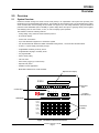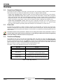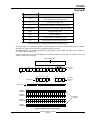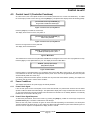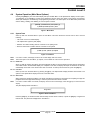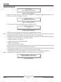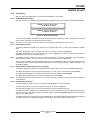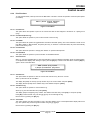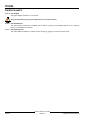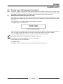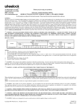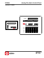
1
D10024
Analog Fire Alarm Control Panel
Operator’s Guide
D10024
System
Reset
Trouble
Silence
Alarm
Silence
Manual
Alarm
YES
NO
ENTER
Letters
Numbers
Keyword
POWER
SYSTEM TROUBLE
TROUBLE SILENCED
ALARM SILENCED
POINT BYPASSED
ALARM
System
Reset
Trouble
S ilen ced
Alarm
Silence
Manual
Al arm
Enable
Keypad
Disable
Keypad
1
2
3
4
5
6
7
8
9
10
11
12
13
14
15
16
17
18
19
20
21
22
23
24
25
26
27
28
29
30
31
32
33
34
35
36
37
38
39
40
41
42
43
44
45
46
47
48
49
50
51
52
53
54
55
56
57
58
59
60
61
62
63
64
65
66
67
68
69
70
71
72
73
74
75
76
77
78
79
80
ALARM
TROUBLE
ALARM
TROUBLE
ALARM
TROUBLE
ALARM
TROUBLE
D10024
This page is intentionally blank.
46521C
D10024 Operator’s Guide
Page 2
Copyright © 2001 Radionics
D10024
Contents
Contents
1.0
Notices ................................................................................................................................................................................. 5
1.1
General Notices .................................................................................................................................................................... 5
1.2
FCC Notice ............................................................................................................................................................................ 5
1.2.1
Part 15 ................................................................................................................................................................................... 5
1.3
UL/NFPA Notice .................................................................................................................................................................... 5
2.0
Overview .............................................................................................................................................................................. 7
2.1
System Overview .................................................................................................................................................................. 7
2.2
Control Level Distinction ...................................................................................................................................................... 8
2.3
Passcodes ............................................................................................................................................................................. 8
2.4
Controls and Displays .......................................................................................................................................................... 8
3.0
Control Level 1 (Display Functions) .............................................................................................................................. 11
3.1
Power Conditions ................................................................................................................................................................ 11
3.2
Trouble Conditions .............................................................................................................................................................. 11
3.3
Alarm Conditions ................................................................................................................................................................ 11
4.0
Control Level 2 (Controller Functions) ......................................................................................................................... 13
4.1
Power Conditions ................................................................................................................................................................ 13
4.1.1
Power Failure Signal .......................................................................................................................................................... 13
4.1.2
Power Failure Signal Response ........................................................................................................................................ 13
4.2
Trouble Conditions .............................................................................................................................................................. 14
4.2.1
Trouble Signals ................................................................................................................................................................... 14
4.2.2
Trouble Signal Response ................................................................................................................................................... 14
4.3
Alarm Conditions ................................................................................................................................................................ 14
4.3.1
Alarm Signals ...................................................................................................................................................................... 14
4.3.2
Alarm Signal Response ...................................................................................................................................................... 14
4.4
System Operation (Main Menu Options) ........................................................................................................................... 15
4.4.1
System Tests ....................................................................................................................................................................... 15
4.4.1.1 LEDs Test ............................................................................................................................................................................ 15
4.4.1.2 LCD Test .............................................................................................................................................................................. 15
4.4.1.3 Zones Test ........................................................................................................................................................................... 15
4.4.2
Time Setting ........................................................................................................................................................................ 17
4.4.3
Enable/Disable Functions .................................................................................................................................................. 17
4.4.3.1 Enable/Disable by Zone ..................................................................................................................................................... 17
4.4.3.2 Enable/Disable Individual Detection Devices (Inputs) ..................................................................................................... 17
4.4.3.3 Enable/Disable Panel Keys ................................................................................................................................................ 17
4.4.3.4 Enable/Disable Delayed Day Mode ................................................................................................................................... 18
4.4.3.5 Enable/Disable Relays ....................................................................................................................................................... 18
4.4.4
Print Functions .................................................................................................................................................................... 19
4.4.4.1 Print Devices ....................................................................................................................................................................... 19
4.4.4.2 Print Events (Event Log) .................................................................................................................................................... 19
4.4.4.3 Print Mode ........................................................................................................................................................................... 19
4.4.4.4 Print Direction ..................................................................................................................................................................... 19
4.4.4.5 Print Disabled ...................................................................................................................................................................... 19
4.4.5
View Functions .................................................................................................................................................................... 19
4.4.5.1 View Devices ....................................................................................................................................................................... 19
4.4.5.2 View Event Log ................................................................................................................................................................... 19
4.4.5.3 View Faults .......................................................................................................................................................................... 19
4.4.5.4 View Outputs ....................................................................................................................................................................... 20
4.4.5.5 View Disablements ............................................................................................................................................................. 20
4.4.5.6 View System Events ........................................................................................................................................................... 20
5.0
Control Level 3 (Programmer Functions) ..................................................................................................................... 21
5.1
Enable/Disable Sounders (NAC Devices) ........................................................................................................................ 21
Index .................................................................................................................................................................................................. 23
Copyright © 2001 Radionics
D10024 Operator’s Guide
Page 3
46521C
D10024
Figures and Tables
Figures
Figure 1: D10024 Fire Alarm Control Panel ....................................................................................................................................... 7
Figure 2: D10024 Controls and Displays ........................................................................................................................................... 9
Figure 3: Control Level 2, Entry Menu 1 .......................................................................................................................................... 13
Figure 4: Control Level 2, Entry Menu 2 .......................................................................................................................................... 13
Figure 5: Main Menu .......................................................................................................................................................................... 13
Figure 6: Enable Menu ...................................................................................................................................................................... 13
Figure 7: Main Menu .......................................................................................................................................................................... 15
Figure 8: Test Menu ........................................................................................................................................................................... 15
Figure 9: Zone Test Menu 1 .............................................................................................................................................................. 15
Figure 10: Zone Test Menu 2 ............................................................................................................................................................ 16
Figure 11: Zone Test Menu 3 ............................................................................................................................................................ 16
Figure 12: Zone Test Menu 4 ............................................................................................................................................................ 16
Figure 13: Main Menu ........................................................................................................................................................................ 16
Figure 14: Enable/Disable Menus .................................................................................................................................................... 17
Figure 15: Outputs Menu .................................................................................................................................................................. 18
Figure 16: Main Menu ........................................................................................................................................................................ 18
Figure 17: Print Menu ........................................................................................................................................................................ 19
Figure 18: View Menu ........................................................................................................................................................................ 19
Figure 19: Outputs Submenu ............................................................................................................................................................ 21
Tables
Table 1: Control Key Functions ........................................................................................................................................................... 8
Table 2: Alphanumeric and Program/Interactive Key Functions ...................................................................................................... 9
Table 3: System Event and Status LEDs ......................................................................................................................................... 10
46521C
D10024 Operator’s Guide
Page 4
Copyright © 2001 Radionics
D10024
Notices
1.0
Notices
1.1
General Notices
These instructions contain procedures to follow in order to avoid personal injury and/or damage to the equipment.
NFPA 72 requires a complete system-wide functional test be performed following any modifications, repair,
upgrades or adjustments made to the system’s components, hardware, wiring, programming and software/
firmware.
The material and instructions covered in this installation guide have been carefully checked for accuracy and are
presumed to be reliable. However, the manufacturer assumes no responsibility for inaccuracies and reserves the right
to modify and revise this installation guide without notice.
This manual covers the operation of the D10024 Analog Fire Alarm Control Panel (FACP). See the D10024 Installation
Guide (P/N: 46482) for instructions on the installation of the D10024.
1.2
FCC Notice
1.2.1
Part 15
This equipment has been tested and found to comply with the limits for a Class A digital device, pursuant to Part 15 of
the FCC Rules. These limits are designed to provide reasonable protection against harmful interference in a commercial
installation. This equipment generates, uses and can radiate radio frequency energy, and, if not installed in accordance
with the instructions, may cause harmful interference to radio communications. However, there is no guarantee that
interference will not occur in a particular installation. If this equipment does cause harmful interference to radio or
television reception, which can be determined by turning the equipment on and off, the user is encouraged to try to
correct the interference by one or more of the following measures:
1.3
1)
Reorient or relocate the receiving antenna.
2)
Increase the separation between the equipment and the receiver.
3)
Connect the equipment into an outlet on a circuit different from that to which the receiver is connected.
4)
Consult the dealer or an experienced radio/TV technician for help.
UL/NFPA Notice
Radionics’ D10024 Analog Fire Alarm Control Panel is UL Listed for NFPA 72, Central Station and Remote Station.
All references to NFPA and related requirements are based upon compliance with the 1993 edition of NFPA 72, National
Fire Alarm Code. Since installation specifications are nearly always based upon a specific edition of a standard which
has been legally adopted by the Authority Having Jurisdiction (AHJ), earlier editions of NFPA standards will generally
apply. Consult with the appropriate AHJ for confirmation.
Copyright © 2001 Radionics
D10024 Operator’s Guide
Page 5
46521C
D10024
Notices
Notes:
46521C
D10024 Operator’s Guide
Page 6
Copyright © 2001 Radionics
D10024
Overview
2.0
Overview
2.1
System Overview
Radionics’ D10024 Analog Fire Alarm Control Panel (FACP) is an expandable control panel that provides point
identification through addressable analog devices. The D10024 has five expansion slots to accommodate plug-in polling
circuit modules. Each of these polling circuit modules can support up to 126 analog addresses, giving the D10024 a
potential of 630 addressable points. Flexibility in system design allows the option of grouping device points together
and identifying them as one location, or zone, in order to simplify system operation.
The D10024 includes the following features:
• Analog design using advanced communications protocol
• 80 character display
• Custom text annunciation
• Up to 630 addresses supported in a stand-alone system
• Can be networked with Radionics’ D8024 and D9024 Analog FACPs, as well as other D10024 FACPs
• 24 VDC, 3 A power supply and battery charger
• Programmable sensitivity levels by device
• Programmable “day/night” sensitivity levels
• PC programmable
• Service mode polling
• Fire test mode
• Event activity logger (up to 500 events)
• Optional local printer
• Suitable for ADA applications
• Meets NFPA National Fire Code standards
Alphanumeric Display
D10024
Alphanumeric
Keys
Control Keys
System
Reset
Trouble
Silence
Alarm
Silence
Manual
Alarm
YES
NO
ENTER
Letters
Numbers
Program/
Interactive Keys
Keyword
LED Display
1
2
3
4
5
6
7
8
9
10
11
12
13
14
15
16
17
18
19
20
21
22
23
24
25
26
27
28
29
30
31
32
33
34
35
36
37
38
39
40
41
42
43
44
45
46
47
48
49
50
51
52
53
54
55
56
57
58
59
60
61
62
63
64
65
66
67
68
69
70
71
72
73
74
75
76
77
78
79
80
ALARM
TROUBLE
ALARM
TROUBLE
ALARM
TROUBLE
Zone/Area
Display
ALARM
TROUBLE
Figure 1: D10024 Fire Alarm Control Panel
Copyright © 2001 Radionics
D10024 Operator’s Guide
Page 7
46521C
D10024
Overview
2.2
Control Level Distinction
The D10024 has three available control levels. At all three levels, the LED display indicates condition, the Zone/Area
LEDs indicate location and determined alarm/trouble information is displayed alphanumerically.
• Control Level 1 (Display Level): Inhibits the system control keys, limiting the front panel function to annunciation.
• Control Level 2 (Controller Level): Allows system control for Fire Drill, Alarm Silence, Trouble Silence and System
Reset. This level also allows Test and Enable/Disable operations, but does not allow access to configuration or
programming functions. At Control Level 2, the alphanumeric display becomes interactive and prompts for system
checks, log functions and key status. Control Level 2 is reached by entering a passcode from Control Level 1.
• Control Level 3 (Programmer’s Level): Allows full system configuration information and is used to program the
system or modify the program. Control Level 3 is reached by passcode from Control Levels 1 or 2. See the Analog
Fire Alarm Control Panels Programming Guide (P/N: 38789) for more information on Control Level 3.
2.3
Passcodes
Ten passcodes are available for D10024 Controllers. Passcodes are programmable. The Control Level 2 passcode is
assigned or changed from Control Level 3, but will not allow access to Control Level 3. See the Analog Fire Alarm
Control Panels Programming Guide (P/N: 38789) for more information on programming and assigning passcodes from
Control Level 3.
The default Control Level 2 passcode is 1234. Be sure to change the Control Level 2 passcode in order to
provide a higher level of panel security. See Section 7.4 in the Analog Fire Alarm Control Panels Programming
Guide (P/N: 38789) to modify the Control Level 2 passcode.
2.4
Controls and Displays
The D10024 has two rows of control keys and three display areas. The upper row of keys, the alphanumeric keys,
normally function as number keys. They can be toggled to letter keys or number keys by pressing the [Letters/Numbers]
key in the program/interactive keys row. The [Shift] key at the left end of the alphanumeric keys toggles between the
upper and lower rows of letters. Hold the [Shift] key while pressing another key to enter the bottom letter. The control
keys row contains four system control keys and three program/interactive keys.
See Tables 1 and 2 for key descriptions and Figure 2 for key locations.
Key Label
Function
Fire Drill
Turns on all NAC devices.
Alarm Silence
Press to silence all NAC devices.
Press again to activate all NAC devices.
Trouble Silence
Acknowledges events and silences the internal buzzer.
System Reset
Cancels all alarm conditions and resets the panel.
Table 1: Control Key Functions
46521C
D10024 Operator’s Guide
Page 8
Copyright © 2001 Radionics
D10024
Overview
Key Label
Function
Shift
Shows user options on the alphanumeric display
Used in programming to allow letter N to Z.
0, 1, 2, 3, 4, 5, 6, 7, 8, 9
Number keys for digits 0 to 9.
><
Scrolls through fires/faults on the alphanumeric display.
Letters/Numbers
Toggles the alphanumeric keys between letters and numbers.
Change
Changes a display option.
Enter
Enters the selection.
No
Press to answer No or terminate an option.
Yes
Press to answer Yes or step through an option.
Table 2: Alphanumeric and Program/Interactive Key Functions
The upper display, the alphanumeric display, is an illuminated two-line, 80-character LED display that gives detailed
information on system events and status, and displays interactive prompts.
The middle display is a row of LEDs that indicate the type of system event and status. See Table 3 for the functions of
the system event and status LEDs.
The lower display area is the zone/area display that indicates the location and type (alarm or trouble) of event. The
D10024 can have up to 80 zones.
Alphanumeric Display
2
1
0
5
4
3
8
7
6
CHANGE
9
Alphanumeric
Keys
SHIFT
A
N
B
O
C
P
D
Q
E
R
F
S
G
T
H
U
System
Reset
Trouble
Silence
Alarm
Silence
I
V
J
W
K
X
Manual
Alarm
L
Y
ENTER
NO
M
Z
YES
Program/
Interactive
Keys
Control Keys
Letters
Numbers
Keyword
LED Display
Sounder
Fault
Earth
ALARM System Trouble Point
Trouble Silenced Bypassed Fault
Sprinkler
Supervisory
CPU
Reset
Alarm
AC
Silenced Power
1
2
3
4
5
6
7
8
9
10
11
12
13
14
15
16
17
18
19
20
21
22
23
24
25
26
27
28
29
30
31
32
33
34
35
36
37
38
39
40
41
42
43
44
45
46
47
48
49
50
51
52
53
54
55
56
57
58
59
60
61
62
63
64
65
66
67
68
69
70
71
72
73
74
75
76
77
78
79
80
ALARM
TROUBLE
ALARM
TROUBLE
Zone/Area
Display
ALARM
TROUBLE
ALARM
TROUBLE
Figure 2: D10024 Controls and Displays
Copyright © 2001 Radionics
D10024 Operator’s Guide
Page 9
46521C
D10024
Overview
System Event and Status LED
Alarm
Function
An input point is in alarm state, or has latched into an alarm state. This clears
when the system is reset.
System Trouble
There is a fault in the system: SLC wiring, power fault, etc. This clears when the
fault has been corrected and the panel has been reset.
Trouble Silenced
The annunciation of a fault condition has been manually silenced by an operator.
This clears when the fault condition has been corrected and the panel has been
reset, or another fault occurs.
Point Bypassed
One or more inputs have been disabled manually by an operator. This clears when
the point(s) are returned to service.
Earth Fault
The system has a short circuit to a foreign ground, such as an SLC conductor
shorted to a heating duct. This clears when the fault has been corrected and the
panel has been reset.
Sounder Fault
This indicates a wiring fault witn a NAC device. It clears when the fault has been
corrected and the panel has been reset.
Sprinkler Supervisory
This indicates a special type of alarm, usually indicating an unsafe condition with a
fire suppression system. It clears when the system has been reset.
CPU Reset
The system has detected an improper operation of the CPU, and has restarted it
automatically. It clears when the system is reset by the operator.
Alarm Silenced
Notification circuits have been manually turned off by an operator, but the system
is still in an alarm state. This clears when the system is reset.
AC Power
Indicates that acceptable AC line power is present.
Table 3: System Event and Status LEDs
46521C
D10024 Operator’s Guide
Page 10
Copyright © 2001 Radionics
D10024
Control Level 1
3.0
Control Level 1 (Display Functions)
At Control Level 1, the control keys are disabled and the control panel functions only as an annunciator. Pressing any
of the control keys will result in a series of interactive messages on the alphanumeric display that end in a prompt for a
Control Level 2 passcode.
The following subsections explain the features options of Control Level 1.
3.1
Power Conditions
When the system is being powered by 120 VAC, the green AC Power LED in the lower right of the LED display will be
lit. The normal alphanumeric display will alternate between a time and date message and a system status message.
If the 120 VAC power source is interrupted, the AC Power LED will flash, the panel buzzer will sound and the System
Trouble and Earth Fault LEDs will light. The alphanumeric display will no longer be illuminated, and the display will show
an “AC Fail” message and provide information about the failure, the status of the standby batteries and the telephone
number for service. Pressing the [Trouble Silence] key will silence the panel buzzer.
3.2
Trouble Conditions
If a device fails to respond, is disabled, the response is not within the normal parameters, or the system detects a fault,
the amber System Trouble or Fault LEDs will light. The amber Trouble LED in the Zone/Area section of the panel will
light to indicate the location, the panel’s buzzer will sound and the alphanumeric display will provide detailed information.
If more than one fault is present, the display will automatically scroll through the first four faults.
3.3
Alarm Conditions
The two red alarm LEDs at the left of the display flash to indicate the system has detected a fire condition. The Zone/
Area alarm LED(s) lights, indicating the alarm location(s) and the alphanumeric display provides detailed information.
If more than one fire is present, the display will automatically scroll through the first four alarms.
Copyright © 2001 Radionics
D10024 Operator’s Guide
Page 11
46521C
D10024
Control Level 1
Notes:
46521C
D10024 Operator’s Guide
Page 12
Copyright © 2001 Radionics
D10024
Control Level 2
4.0
Control Level 2 (Controller Functions)
At Control Level 2, the control panel functions as a Controller (see Section 2.2 “Control Level Distinction”). To enable
the control keys (to enter Control Level 2), press the [Shift] key. The alphanumeric display shows the following prompt:
[Panel ACTIVE control keys INHIBITED] [1]
Do you want to enable the control keys?
Figure 3: Control Level 2, Entry Menu 1
Press the [Yes] key to enable the control keys.
The display shows Control Level 2, Entry Menu 2.
[Panel ACTIVE control keys INHIBITED] [1]
Please enter password
Figure 4: Control Level 2, Entry Menu 2
Enter the four digit Control Level 2 passcode.
The display shows the Main Menu.
[ACTIVE] 1) Commission 2) Test 3) Time [1]
4) Enable 5) Disable 6) Print 7) View
Figure 5: Main Menu
The D10024 has ten Control Level 2 passcodes available that are assigned from Control Level 3 (Programmer’s Level).
Press the [4] key on the alphanumeric key row. The display shows the Enable Menu.
ENABLE: 1) Zone 2) Input 3) Keys
4) Day Mode 5) Outputs
Figure 6: Enable Menu
Press the [3] key on the alphanumeric row. The display returns to the Main Menu (see Figure 5). The control keys are
now enabled for the amount of time programmed into the panel. At the end of the programmed time period, the panel
will automatically inhibit the control keys.
The following subsections describe specific conditions that may arise while the D10024 is operating, and explain how
to interface with the panel to resolve these conditions.
4.1
Power Conditions
The D10024 supervises its AC power supply and standby batteries.
4.1.1
Power Failure Signal
If the 120 VAC power source is interrupted, the AC Power LED will flash, the panel buzzer will sound and the amber
System Trouble and Earth Fault LEDs will light. The alphanumeric display will no longer be illuminated and it will show
an “AC Fail” message and provide information about the failure and the status of the standby batteries. If the standby
batteries fail, the AC Power LED will go out.
4.1.2
Power Failure Signal Response
To silence the panel buzzer, enter Control Level 2 by pressing the [Shift] key, enable the control keys and press the
[Trouble Silence] key. The amber Trouble Silence LED will light.
When the 120 VAC power is restored, the green AC Power LED will stop flashing, but will remain lit, and the System
Trouble and Earth Fault LEDs will go out. The amber CPU Reset LED lights while the system resets itself and goes out
when the reset is complete. The alphanumeric display returns to normal.
Copyright © 2001 Radionics
D10024 Operator’s Guide
Page 13
46521C
D10024
Control Level 2
4.2
Trouble Conditions
The system responds to other-than-normal conditions that are not caused by alarms by sounding the internal buzzer
and initiating a Trouble Condition.
4.2.1
Trouble Signals
If a device fails to respond, is disabled, the response is not within the normal parameters, or the system detects a fault,
the amber System Trouble or Fault LED will light. In addition, the amber Trouble LED in the Zone/Area section of the
panel will light to indicate the location, the panel’s internal buzzer will sound and the alphanumeric display will provide
detailed information.
4.2.2
Trouble Signal Response
To acknowledge a trouble signal, enter Control Level Two by pressing the [Shift] key, enable the control keys and press
the [Trouble Silence] key to mute the internal buzzer (under certain circumstances, the system may override the
mute). The amber Trouble Silenced LED will light to indicate that condition. The system will not allow a reset until the
problem is corrected. If necessary, the system allows disabling of individual devices and zones (see Section 4.5.3
“Enable/Disable Functions”). After correcting the problem, press the [System Reset] key. The amber Trouble Silenced
LED will go out and the alphanumeric display will return to normal.
4.3
Alarm Conditions
The D10024 will signal an alarm if it detects an alarm condition or a fire drill test.
4.3.1
Alarm Signals
If the D10024 initiates an alarm condition, the red Alarm LEDs at the left of the LED display flash to indicate the system
has detected a fire condition and has activated its Notification Appliance Circuit (NAC) devices (horns, strobes, etc.),
the internal buzzer sounds, Zone/Area Alarm LED(s) light indicating the event location and the alphanumeric display
provides detailed information.
To test the alarm system, enter Control Level 2 by pressing the [Shift] key, enable the control keys and press the [Fire
Drill] key. The panel will activate all system NAC devices. The red Alarm LEDs at the left of the LED display will flash
and the internal buzzer will sound. The alphanumeric display will show a “Fire Test” message.
4.3.2
Alarm Signal Response
Press the [Alarm Silence] key to turn off all external NAC devices. The Alarm Silenced LED will light. Pressing the
[Alarm Silence] key again turns on all external NAC devices.
Press the [Trouble Silence] key to turn the panel buzzer off. The amber Trouble Silenced LED will light.
Press the [System Reset] key to reset the system. The Alarm and Trouble Silenced LEDs will go out and the alphanumeric
display will return to normal.
Note:
The D10024 can be reset at any time, however if a device is still in alarm when the D10024 is reset, the D10024 will go
back into an alarm condition.
To return the system to Control Level 1, press the [Shift] key and select 5) Disable from the alphanumeric display.
Then select 3) Keys from the display. The panel will briefly display the Control Level 2 Entry Menu 2 and then revert to
the normal display (alternating between a time and date display and a system status message).
Press the [Fire Drill] key to verify that the keys are disabled. The display will prompt “Do you want to enable the control
keys?”
Press the [No] key. The display will return to normal.
46521C
D10024 Operator’s Guide
Page 14
Copyright © 2001 Radionics
D10024
Control Level 2
4.4
System Operation (Main Menu Options)
Pressing the [Shift] key from the normal display will open the Main Menu on the alphanumeric display. The first option,
1) Commission, is not available to Control Level 2 Operators. See the Analog Fire Alarm Control Panels Programming
Guide (P/N: 38789) for commissioning and programming information. The other options on the Main Menu permit tests
and the setting, enabling and disabling of various system functions.
[ACTIVE] 1) Commission 2) Test 3) Time [1]
4) Enable 5) Disable 6) Print 7) View
Figure 7: Main Menu
4.4.1
System Tests
Select 2) Test from the Main Menu to open the Test Menu. This menu allows the Control Level 2 user to test the
following:
• The LEDs on the Front Panel Display
• The alphanumeric (liquid crystal) display
• Detection and alarm initiating devices connected to the polling circuit
• NAC and other alarm condition devices connected to the system
1) LEDs 2) LCD 3) Zones 4) Outputs
Figure 8: Test Menu
Note:
If no action is taken, the display reverts to the normal display after one minute.
Note:
The fourth option in the Test Menu, 4) Outputs, is not available to Control Level 2 Operators.
4.4.1.1 LEDs Test
Select 1) LEDs by pressing the [1] key. The panel will flash all LEDs on the LED display and step through all the alarm
and trouble LEDs in the Zone/Area display. On completion of the test, the display will report the results of the test and
automatically revert back to the normal menu after one minute. To interrupt and end the test, press the [No] key.
4.4.1.2 LCD Test
Select 2) LCD from the Main Menu by pressing the [2] key. The alphanumeric display will flash all characters in all
spaces on the alphanumeric display and return to the Main Menu.
4.4.1.3 Zones Test
Select 3) Zones by pressing the [3] key. The Zones Test allows the operator to test devices on the polling circuit(s) and
peripheral device circuit(s) without having to reset the panel after each device is tested.
Note:
If no action is taken within one minute, the display reverts to the normal display. Press the [>] key to restore the Test
display.
The panel displays Zone Test Menu 1.
Ring bells?
Figure 9: Zone Test Menu 1
Press the [Yes] key to activate the NAC devices briefly as each device is tested, or press the [No] key to bypass the
indicator test. The panel then displays Zone Test Menu 2.
Copyright © 2001 Radionics
D10024 Operator’s Guide
Page 15
46521C
D10024
Control Level 2
Test from zone?
(key in number, then press “Enter’)
Figure 10: Zone Test Menu 2
Enter the number of the first zone to be tested and press [Enter]. The panel will then display Zone Test Menu 3. If, for
example, “12” is keyed in, the display would show:
Test from 12 to zone ?
(key in number, then press “Enter”)
Figure 11: Zone Test Menu 3
If “15” is keyed in, the panel would display the Walk Test Mode as follows:
Test from 12 to Zone 15
----------W----------
Figure 12: Zone Test Menu 4
The moving “W” across the lower line alternates with a “Press NO to EXIT” message.
Note:
Once the display indicates the panel is in the Walk Test Mode, the display will not revert to normal. The panel will
terminate the test and sound the panel buzzer if there is no activity for a 20 minute period.
The operator may test devices within the zone parameters shown on the display. The panel responds to each test by:
• Displaying an activation message on the alphanumeric display
• Entering the activation in the event log
• Lighting the alarm LED in the Zone/Area display
• Sounding the panel buzzer
• Lighting the LED at the device in alarm
After a few seconds, the panel will automatically reset and turn off the device LED. The panel allows up to one minute
for smoke devices to clear. The operator may then test the next device.
If the panel detects an alarm condition in a zone other than those being tested, all NAC devices and relays will activate
as programmed. NAC devices will continue to operate until silenced from the panel.
Terminate the Walk Test by pressing the [No] key. The display will return to the Main Menu (see Figure 13).
Note:
The fourth option in the Test Menu, 4) Outputs, is not available to Control Level 2 Operators.
[ACTIVE] 1) Commission 2) Test 3) Time [1]
4) Enable 5) Disable 6) Print 7) View
Figure 13: Main Menu
46521C
D10024 Operator’s Guide
Page 16
Copyright © 2001 Radionics
D10024
Control Level 2
4.4.2
Time Setting
Select 3) Time from the Main Menu to change the time displayed on the D10024.
4.4.3
Enable/Disable Functions
Main Menu option four, 4) Enable, opens the Enable Menu. Main Menu option five, 5) Disable, opens the Disable Menu.
ENABLE: 1) Zone 2) Input 3) Keys
4) Day Mode 5) Outputs
DISABLE: 1) Zone 2) Input 3) Keys
4) Day Mode 5) Outputs
Figure 14: Enable/Disable Menus
The content of the Enable and Disable menus is identical, allowing the operator to enable or disable zones, individual
devices (input), panel keys, day modes and outputs (relays).
Note:
NAC devices such as bells, horns and strobes cannot be enabled or disabled from Control Level 2.
4.4.3.1 Enable/Disable by Zone
To enable or disable input signals from devices by zone, select the first option, 1) Zone, from the Enable or Disable
Menu.
The display will prompt for the zone number. Key in the zone number and press the [Enter] key.
The display will repeat the zone number and ask “OK?”. Press the [Yes] key to confirm. The panel will then enable or
disable all the input devices in the selected zone.
Note:
Any disabled circuit-driven device or relay on a circuit will still operate on output as programmed. Only the input signal
will be disabled. However, manual pull stations (alarm boxes) within the zone are not disabled.
When a device is disabled, the amber Point Bypassed LED on the LED display will light. The amber Trouble LED in the
corresponding zone of the Zone/Area display will also light, and the panel will display a disable message on the
alphanumeric display.
4.4.3.2 Enable/Disable Individual Detection Devices (Inputs)
To enable or disable input signals from individual detection devices, select 2) Input from the Enable/Disable Menu.
The display will prompt for the polling circuit (loop) number (1-5). Key in the circuit number and press [Enter].
The display will then prompt for the address of the device. Key in the address and press [Enter].
The display will then repeat the circuit number and address. Press the [Yes] key.
Note:
Any disabled circuit-driven device or relay on a circuit will still operate on output as programmed. Only the input signal
will be disabled.
4.4.3.3 Enable/Disable Panel Keys
To enable panel keys, press any of the control keys except the [No] key, or press the [>] key.
The panel will prompt “Do you want to enable the control keys?”. Press the [Yes] key.
The panel then prompts for the Control Level 2 passcode. Key in the appropriate passcode.
The panel keys will be enabled for the programmed period of time. The display reverts to the Main Menu (see Figure
13). After one minute, the display reverts to the normal display. Pressing the [System Reset] key will also return the
display to the normal display.
To disable the panel keys, select 3) Keys from the Disable Menu. The display indicates that the panel keys are inhibited
and then returns to the normal display. Disabling the panel keys returns the D10024 to Control Level 1.
Copyright © 2001 Radionics
D10024 Operator’s Guide
Page 17
46521C
D10024
Control Level 2
4.4.3.4 Enable/Disable Delayed Day Mode
The Delayed Day Mode is configured from Control Level 3. This mode causes the panel to respond to high sensor
signals by sounding the panel buzzer and displaying a warning message at the alphanumeric display. The panel delays
alarm activation for a programmed period. Configuration parameters allow variations in time of day and zones affected.
The Control Level 2 operator may enable or disable the Delayed Day Mode through the Enable or Disable Menu.
To enable the Delayed Day Mode, select 4) Day Modes from the Enable Menu.
The display will prompt for the programmed number of days. To accept as prompted, press the [Yes] key.
To change from the prompted number of days, press the [Change] key, enter the desired number of days and press the
[Enter] key.
Enter 0 days to disable the Delayed Day Mode. Enter 200 days to permanently enable the Delayed Day Mode.
Note:
If the Delayed Day Mode has not been programmed into the panel, pressing 4) Day Modes from the Enable or Disable
Menu will return the alphanumeric display to the Main Menu.
4.4.3.5 Enable/Disable Relays
Press [5] for Disable from the Main Menu to disable relays during testing. The panel will then display the Disable Menu.
Press [5] for Outputs. The display shows the following:
1) Sounders 2) Relays
ENABLED
ENABLED
Figure 15: Outputs Menu
Note:
NAC devices such as bells, horns and strobes, all of which are sounders, cannot be enabled or disabled from Control
Level 2.
Select 2) Relays. The panel buzzer will sound, the System Trouble LED will light and the alphanumeric display message
indicates that the relays are disabled.
Press the [Trouble Silence] key to silence the buzzer. The Trouble Silenced LED will light.
Note:
Any disabled outputs must be enabled before the system can be reset.
To enable the outputs, press the [No] key to revert to the Main Menu.
[ACTIVE] 1) Commission 2) Test 3) Time [1]
4) Enable 5) Disable 6) Print 7) View
Figure 16: Main Menu
Press the [4] key to enter the Enable Menu.
Press [5] for Outputs.
Press [5] for Relays. The system will reset and the Trouble Silenced LED will go out.
Press the [No] key to return to the Main Menu.
46521C
D10024 Operator’s Guide
Page 18
Copyright © 2001 Radionics
D10024
Control Level 2
4.4.4
Print Functions
To enter the Print Menu, select 6) Print from the Main Menu. This menu controls the operation of the front panel printer
(if installed).
PRINT: 1) Devices 2) Events 5) Disabled
3) Mode 4) Setup
Figure 17: Print Menu
4.4.4.1 Print Devices
This option allows the operator to print out the current state and the text assigned to all devices on a polling circuit
(loop).
4.4.4.2 Print Events (Event Log)
This option allows the operator to print out the contents of the event log.
4.4.4.3 Print Mode
This option allows the operator to toggle between manual and automatic printing. The current selection is shown on the
Print Menu display. In Manual Mode, the printer prints only on demand. In Automatic Mode, the printer automatically
prints events as they occur.
4.4.4.4 Print Direction
This option allows the operator to change print direction on panel-mounted printers.
4.4.4.5 Print Disabled
This option allows the operator to print the location of all disabled devices.
4.4.5
View Functions
Select 7) View from the Main Menu to enter the View Menu. This menu displays information about the selected option
on the alphanumeric display. After viewing an option, press the [No] key to return to the View Menu. Press the [No] key
again to return to the Main Menu.
VIEW: 1) Device 2) Log 3) Faults
4) Outputs 5) Disablements 6) Sys Events
Figure 18: View Menu
4.4.5.1 View Devices
This option allows the operator to view the current state and text of any device on a circuit.
Select 1) Devices from the View Menu.
The display will prompt for the loop (circuit) number. Key in the circuit number and press [Enter].
The display will then prompt for the address. Key in the address and press [Enter].
4.4.5.2 View Event Log
This option allows the operator to view the Event Log.
Select 2) Log from the View Menu and press [Enter].
The display prompts a beginning entry number. The default is the latest entry. Press [Yes] to accept the prompt.
Press [No] to select another entry. Use the [<] [>] keys to scroll through the log.
Exit this menu by pressing the [No] key.
4.4.5.3 View Faults
This option displays the panel fault status. This is the same display as the normal alphanumeric display without the
logo. The operator may scroll through all the faults using the [<] [>] keys.
Exit this menu by pressing the [No] key.
Copyright © 2001 Radionics
D10024 Operator’s Guide
Page 19
46521C
D10024
Control Level 2
4.4.5.4 View Outputs
This option displays information on the outputs.
Using the Alarm Silence Key forces all NAC devices to an OFF condition.
4.4.5.5 View Disablements
This option displays information on disabled devices. Select 1) Zones to view disabled devices by zone. Select 2)
Inputs to view disabled input devices.
4.4.5.6 View System Events
This option displays information on system events. Use the [<] [>] keys to scroll through the events.
46521C
D10024 Operator’s Guide
Page 20
Copyright © 2001 Radionics
D10024
Control Level 3
5.0
Control Level 3 (Programmer Functions)
Note:
Commission, configure, networking and certain disable options are not available to Control Level 2 operators. These
options are reserved for Control Level 3 operators. See the Analog Fire Alarm Control Panels Programming Guide
(P/N: 46482) for complete information on commissioning and programming the D10024 Analog FACP.
5.1
Enable/Disable Sounders (NAC Devices)
All sounders (NAC devices such as horns, bells, strobes, etc.) and relays can be enabled or disabled from the control
panel during testing. Disabling NAC devices requires a Control Level 3 passcode. No passcode is required to enable
NAC devices.
From the Main Menu, press [5] for Disable. The Disable Menu is displayed.
Press [5] for Outputs. The display shows:
1) Sounders 2) Relays
ENABLED
ENABLED
Figure 19: Outputs Submenu
Press 1) Sounders. The display prompts for the Control Level 3 passcode. Enter the passcode. The panel buzzer will
sound, the System Trouble LED will light and the display message will indicate that the output is disabled.
Press the [Trouble Silence] key to silence the buzzer. The Trouble Silenced LED will light.
The disabled output must be enabled before the system can be reset.
To enable the outputs, press the [No] key to revert to the Main Menu.
Press the [4] key to enter the Enable Menu.
Press [5] for Outputs.
Press [1] for Sounders. The system will reset and the Trouble Silenced LEDs will go out.
Copyright © 2001 Radionics
D10024 Operator’s Guide
Page 21
46521C
D10024
Control Level 3
Notes:
46521C
D10024 Operator’s Guide
Page 22
Copyright © 2001 Radionics
D10024
Index
Index
A
Alarm Signal Response .............................................. 14
Alarm Signals ............................................................... 14
Alphanumeric and Program/Interactive Key Functions 9
C
Conditions
Alarm Conditions ..................................................... 11, 14
Power Conditions .................................................... 11, 13
Trouble Conditions .................................................. 11, 14
Control Key Functions ................................................. 8
Control Level 1 (Display Functions) ........................... 11
Control Level 2 (Controller Functions) ....................... 13
Control Level 3 (Programmer Functions) ................... 21
Control Level Distinction
Control Level 1 (Display Level) .............................. 8
Control Level 2 (Controller Level) .......................... 8
Control Level 3 (Programmer’s Level) ................... 8
Controls and Displays ................................................. 8
M
N
Notices
FCC Notice .............................................................. 5
General Notices ....................................................... 5
UL/NFPA Notice ...................................................... 5
O
Overview
Main Menu Options
Enable/Disable Functions
Enable/Disable by Zone ...................................... 17
Enable/Disable Delayed Day Mode ................... 18
Enable/Disable Individual Detection Devices ...... 17
Enable/Disable Panel Keys ................................ 17
Enable/Disable Relays ........................................ 18
Print Functions
Print Direction ...................................................... 19
Print Functions
Print Devices ....................................................... 19
Print Disabled ...................................................... 19
Print Events (Event Log) ..................................... 19
Print Mode ........................................................... 19
Test
LEDs Test ............................................................. 15
Tests
LCD Test .............................................................. 15
System Tests ....................................................... 15
Zones Test ........................................................... 15
Time Setting ............................................................. 17
View Functions
View Devices ....................................................... 19
View Disablements .............................................. 20
View Event Log .................................................... 19
View Faults .......................................................... 19
View Outputs ....................................................... 20
View System Events ........................................... 20
Copyright © 2001 Radionics
Menus
Control Level 2, Entry Menu 1 ................................ 13
Control Level 2, Entry Menu 2 ................................ 13
Enable Menu ............................................................ 13
Enable/Disable Menus ............................................ 17
Main Menu .......................................... 13, 15, 16, 18
Outputs Menu .......................................................... 18
Print Menu ................................................................ 19
Test Menu ................................................................. 15
View Menu ............................................................... 19
Zone Test Menu 1 .................................................... 15
Zone Test Menu 2 .................................................... 16
Zone Test Menu 3 .................................................... 16
Zone Test Menu 4 .................................................... 16
...................................................................... 7
P
Passcodes ................................................................... 8
Power Failure Signal ................................................... 13
Power Failure Signal Response ................................. 13
S
System Overview ......................................................... 7
T
Trouble Signal Response ............................................ 14
Trouble Signals ............................................................ 14
D10024 Operator’s Guide
Page 23
46521C
© 2001 Radionics, a division of Detection Systems, Inc.
PO Box 80012, Salinas, CA 93912-0012 USA
Customer Service: (800) 538-5807
46521C
Operator’s Guide
8/01
D10024
Page 24 of 24