1
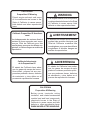
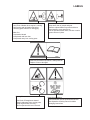
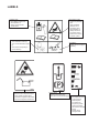
4165607-GB Rev. A ® Operator's Manual 36 HYDRO Z-CONTROL MID-16HP KAW SIDE DISCHARGE SELF PROPELLED WALK BEHIND MOWER Product code: 933308 36 HYDRO Z-CONTROL MID-16HP KAW REAR DISCHARGE SELF PROPELLED WALK BEHIND MOWER Product code: 933309 (Parts Manual: 4165606) GB United Kingdom RJL 100 / February 2012 CALIFORNIA WARNING Proposition 65 Warning Diesel engine exhaust and some of its constituents are known to the State of California to cause cancer, birth defects and other reproductive harm. The engine exhaust from this product contains chemicals known to the State of California to cause cancer, birth defects or other reproductive harm. Californie Proposition 65 Avertissement Les échappements des moteurs diesel et certains de leurs composés sont reconnus par l’Etat de Californie pour être cancérigènes, provoquer des défauts congénitaux et d’autres dangers en matière de reproduction. AVERTISSEMENT L’émission du moteur de ce matériel contient des produits chimiques que l’Etat de Californie considère être cancérigènes, provoquer des défauts congénitaux et d’autres dangers en matière de reproduction. ADVERTENCIA California Advertencia de la Proposicion 65 El estado de California hace saber que los gases de escape de los motores diesel y algunos de sus componentes producen cáncer, defectos de nacimiento y otros daños en el proceso de reproducción humana. El estado de California hace saber que los gases de escape de este producto contienen productos quÍmicos que producen cáncer, defectos de nacimiento y otros daños en el proceso de reproducción humana. CALIFORNIA Proposition 65 Warning Battery posts, terminals, wiring insulation, and related accessories contain lead and lead compounds, chemicals known to the State of California to cause cancer and birth defects or other reproductive harm. WASH HANDS AFTER HANDLING. IMPORTANT MESSAGE Thank you for purchasing this Schiller Grounds Care, Inc. product. You have purchased a world class mowing product, one of the best designed and built anywhere. This machine comes with an Operation and Safety Manual and a separate Setup, Parts and Maintenance Manual. The useful life and good service you receive from this machine depends to a large extent on how well you read and understand these manuals. Treat your machine properly, lubricate and adjust it as instructed, and it will give you many years of reliable service. Your safe use of this Schiller Grounds Care, Inc. product is one of our prime design objectives. Many safety features are built in, but we also rely on your good sense and care to achieve accident-free operation. For best protection, study the manuals thoroughly. Learn the proper operation of all controls. Observe all safety precautions. Follow all instructions and warnings completely. Do not remove or defeat any safety features. Make sure those who operate this machine are as well informed and careful in its use as you are. See a Schiller Grounds Care, Inc. dealer for any service or parts needed. Schiller Grounds Care, Inc. service ensures that you continue to receive the best results possible from Schiller Grounds Care, Inc. products. You can trust Schiller Grounds Care, Inc. replacement parts because they are manufactured with the same high precision and quality as the original parts. Schiller Grounds Care, Inc. designs and builds its equipment to serve many years in a safe and productive manner. For longest life, use this machine only as directed in the manuals, keep it in good repair and follow safety warnings and instructions. You'll always be glad you did. Schiller Grounds Care, Inc. One Bob Cat Lane Johnson Creek, WI 53038-0469 TABLE OF CONTENTS PAGE SAFETY............................................................................................................................................................. 4 LABELS..........................................................................................................................................................5-7 GENERAL INSTRUCTIONS........................................................................................................................8-10 CONTROLS............................................................................................................................................... 11, 12 MACHINE OPERATION.............................................................................................................................13-15 HEIGHT OF CUT........................................................................................................................................16-18 BELT REPLACEMENT.................................................................................................................................... 19 ADJUSTMENTS.........................................................................................................................................20-23 SPECIFICATIONS......................................................................................................................................24-27 2006/42/EC These are the Original instructions verified by Schiller Grounds Care, Inc. 08-2010 SAFETY NOTICE !!! Unauthorized modifications may present extreme safety hazards to operators and bystanders and could also result in product damage. Schiller Grounds Care, Inc. strongly warns against, rejects and disclaims any modifications, add-on accessories or product alterations that are not designed, developed, tested and approved by Schiller Grounds Care, Inc. Engineering Department. Any Schiller Grounds Care, Inc. product that is altered, modified or changed in any manner not specifically authorized after original manufacture–including the addition of “after-market” accessories or component parts not specifically approved by Schiller Grounds Care, Inc.–will result in the Schiller Grounds Care, Inc. Warranty being voided. Any and all liability for personal injury and/or property damage caused by any unauthorized modifications, add-on accessories or products not approved by Schiller Grounds Care, Inc. will be considered the responsibility of the individual(s) or company designing and/or making such changes. Schiller Grounds Care, Inc. will vigorously pursue full indemnification and costs from any party responsible for such unauthorized post-manufacture modifications and/or accessories should personal injury and/or property damage result. This symbol means: ATTENTION! BECOME ALERT! Your safety and the safety of others is involved. Signal word definitions: The signal words below are used to identify levels of hazard seriousness. These words appear in this manual and on the safety labels attached to Schiller Grounds Care, Inc. machines. For your safety and the safety of others, read and follow the information given with these signal words and/or the symbol shown above. DANGER indicates an imminently hazardous situation which, if not avoided, WILL result in death or serious injury. WARNING indicates a potentially hazardous situation which, if not avoided, COULD result in death or serious injury. CAUTION indicates a potentially hazardous situation which, if not avoided, MAY result in minor or moderate injury. It may also be used to alert against unsafe practices or property damage. CAUTION used without the safety alert symbol indicates a potentially hazardous situation which, if not avoided, MAY result in property damage. MODEL NUMBER: This number appears on sales literature, technical manuals and price lists. SERIAL NUMBER: This number appears only on your mower. It contains the model number followed consecutively by the serial number. Use this number when ordering parts or seeking warranty information. LABELS Rotating Blades - Stay clear of blades when engine is running. - Stop engine and let blades stop before removing grass collector or unclogging. Blades Cut - Amputation Hazard - Keep hands and feet clear. - Keep hands away from moving parts Thrown Objects Hazard - Keep area clear of people and pets. - Remove objects blade may strike and throw. - Stop blades to cross gravel ares. - Do not operate without chute, mulcher or entire grass collector in place. Operation & Safety Manual - Read and understand Operation & Safety Manual. - Replace if lost or damaged. Rotating Parts - Cut/Crush /Entanglement hazard. - Keep hands away from moving parts. - Stop engine before servicing. - Do not operate with cover removed. Blade Bolt Installation - Conical washer must be positioned as shown. - See Operation & Safety manual for blade changing instructions. LABELS Hydraulic Fluid - Fill to bottom of filler neck. - See Operation & Safety manual for fluid specifications. Fuel Valve - Turn clockwise to close (0). - Turn counterclockwise to open (I). - Close before transporting to prevent flooding. 2000650 Batteries Produce Explosive Gases - Keep sparks and flame away. - Disconnect negative terminal first. - Reconnect negative terminal last. High Pressure Fluid - Leaks can penetrate skin. - Seek immediate attention for oil penetration injury. - See Operation & Safety manual for procedures to find leaks and to service hydraulic system. Tire Inflation - Inflate tires to 0.97 kg/cm2 [14lb/in2] Parking Brake - Pull lever back to engage. - Push lever forward to disengage. Speed Control - Use adjustment knob to set maximum forward speed. - The further the stop bar is pushed forward, the faster the maximum forward speed. - Speed can be changed while LABELS Tire Inflation - Inflate tires to 1 kg/cm2 [14psi] Operation & Safety Manual - Read and understand Operation & Safety Manual. - Replace if lost or damaged. 4120256 Service /Maintenance - Stop engine. - Remove key and disconnect spark plug wire. - Consult Operation & Safety manual for procedures. Slope Hazard - Do not use on wet or slippery slopes. - Mow across slopes. Thrown Objects - Keep bystanders a safe distance away. - Remove objects on ground blade may strike - Stop blades before crossing gravel. Refueling (Flammable Liquids) - Do not smoke. - Stop engine. - Do not spill fuel. - Do not overfill. (Allow 25mm for fuel expansion) GENERAL INSTRUCTIONS Before using machine for the first time, check engine and hydraulic fluid levels and lubricate all points. j) Never operate the equipment in wet grass. Always be sure of your footing. Keep a firm hold on the handle and walk, never run. TRAINING a) Read the operator’s manual carefully. All rotary grass cutters are potentially dangerous. No person should operate the machine unless they are familiar with the controls and the proper use of the machine. OPERATION a) Do not operate the engine in a confined space where dangerous carbon monoxide fumes can collect. b) Never allow children or people unfamiliar with these instructions to use the mower. Local regulations may restrict the age of the operator. b) Mow only in daylight or in good artificial light. c) Keep the area of operation clear of all persons, particularly small children, and pets. e) With walk behind machines, mow across the slopes, not up and down. d) Keep in mind that the operator or user is responsible for accidents or hazards occurring to other people or their property. PREPARATION a) Do not operate the equipment when barefoot or wearing open sandals. Always wear substantial footwear and long trousers. b) Wear hearing appropriate protection. c) Thoroughly inspect the area where the equipment is to be used and remove all rocks, toys, wire or other debris which may be picked up or thrown by the machine. d) Petrol (gasoline) is highly flammable. Store petrol (gasoline) only in a container specifically designed for gasoline storage in a cool, dry place away from sparks and open flame. When refueling or checking fuel level: Stop engine. Allow to cool. Refuel outdoors only. Do not smoke. Use a funnel. Do not overfill. Clean up spills and move machine away from spills before starting. Replace caps tightly on fuel containers & tanks securely. e) Replace faulty mufflers. f) Before using, always visually inspect to see that the blades, blade bolts and cutter assembly are not worn or damaged. Replace worn or damaged blades and bolts. g) On multi-bladed machines, take care as rotating one blade can cause other blades to rotate. h) Disengage the self-propelled mechanism or drive clutch on units so equipped before starting the engine (motor). i) Never attempt to make adjustments while the engine (motor) is running. c) Always be sure of your footing on slopes. d) Walk, never run. f) Exercise extreme caution when changing direction on slopes. g) Do not mow excessively steep slopes. h) Use extreme caution when reversing or pulling the mower towards you. Be sure the area behind is clear. i) Stop the blades if the mower has to be tilted for transportation, when crossing surfaces other than grass and when transporting the mower to and from the area to be mowed. j) Never operate the mower without proper guards, plates, grass catcher or other safety protective devices in place. k) Do not change the engine governor settings or overspeed the engine. l) Disengage all blades and drive clutches before starting the engine. m) Start the engine or switch on the motor carefully according to instructions and with feet well away from the blades. n) Do not start the engine when standing in front of the discharge chute. o) Do not put hands or feet near or under rotating parts. Keep clear of the discharge opening at all times. p) Never pick up or carry a mower while the engine is running. GENERAL INSTRUCTIONS q) Stop the engine, wait for the blades to come to a complete stop, and disconnect the spark plug wire: before clearing blockages or unclogging chute. before checking, cleaning or working on the mower. after striking a foreign object. Inspect the mower for damage and have repairs made before restarting and operating the mower. if mower starts to vibrate abnormally, shut off machine immeadiately. Vibration is generally a warning of trouble. Inspect the mower for damage and have repairs made as needed before restarting. r) Stop the engine (motor): whenever you leave the mower. before refuelling. s) Shut the engine (motor) off and wait until the blades come to a complete stop before removing the grass catcher or unclogging chute. t) Reduce the throttle setting during engine (motor) shut down and, if the engine is provided with a shut-off valve, turn the fuel off at the conclusion of mowing. u) Go slow when using a trailing seat. v) Keep washout ports and other mower-housing service openings closed when mowing. x) Do not engage PTO at full throttle. Throttle midway between idle and highest possible engine speed. y) Do not start the cutting blades until you are ready to start mowing. z) Do not carry passengers. aa)Do not operate where flying debris may injure people or damage property. Keep people and pets at a safe distance. ab)Do not use if there are any doubts about safety. ac) Keep labels, guards and shields in place. Replace operators manual if lost or damaged. ad) Obey safety instructions. Failure to do so may cause injury to yourself or others. ae)Do not defeat interlocks. Check operation daily. af) Do not allow children, unskilled or untrained persons to operate machine. ag)Do not operate machine while under the influence of drugs, alcohol, and any other condition of impairment. ah)Check blade clutch operation. Adjust or have any problems repaired. OPERATING ON SLOPES USE EXTRA CARE WHEN WORKING ON SLOPES. BEFORE OPERATING ON SLOPES, EVALUATE THE RISKS INVOLVED. With walk behind machines, mow across slopes, not up and down. With ride-on machines, mow up and down slopes, not across, except for zero turn machines. Zero turn machines should mow across slopes. Be alert to dips and rises which change the general slope. Watch for holes, rocks and roots in the terrain and other hidden hazards. Keep away from drop-offs. Avoid ground conditions which will cause the machine to slide. If the operator is uncomfortable or unsure of the machines stability, operation on these slopes should cease immediately. The ultimate responsibility for safe operation on slopes, rests with the operator. Use lower speeds and exercise extreme caution on slopes and especially in sharp turns to prevent tipping and loss of control. Use extra caution when changing direction on slopes. GENERAL INSTRUCTIONS FUEL LEAVING THE DRIVING POSITION Park the machine on level ground. Before leaving the driving position, stop the engine, make sure all moving parts are stationary and that the traction control levers are in the neutral position. Apply parking brake. MAINTENANCE AND ADJUSTMENTS Disconnect spark plug wire(s) before doing any maintenance. Particular care must be taken when adjusting the carburetor while the engine is running. Keep hands and feet clear. Shut off PTO. When working underneath lifted parts or machines, make sure adequate support is provided. WARNING – Petrol (gasoline) and diesel fuels are flammable; gasoline vapors are explosive. Use extra care when handling. – Store only in containers specifically designed for fuel. – When refueling or checking fuel level: - Stop the engine and allow to cool; - Do not smoke; - Refuel outdoors only; - Use a funnel; - Do not overfill; - If fuel is spilled, do not attempt to start the engine until the spill is cleaned up and vapors have cleared. Do not dismantle the machine without releasing or restraining forces which can cause parts to move suddenly. Sparks from static electricity can start fires or cause explosions. Flowing fuel can generate static electricity. To prevent static electricity sparks: Keep all nuts, bolts and screws tight to be sure the equipment is in safe working condition. – Do not fill containers in a vehicle or on a truck or trailer bed with a plastic liner. Fill containers on the ground away from the vehicle. – When practical, remove gas powered equipment from the truck or trailer and refuel it on the ground. If equipment must be refueled on the truck or trailer, refuel from a portable container rather than a dispenser nozzle. – Keep the dispenser nozzle in contact with the rim of the fuel tank or container opening until fueling is complete. Do not use a nozzle lock-open device – Replace caps on fuel cans and tanks securely. Check the grass catcher frequently for wear and deterioration. Replace parts if worn, damaged, or faulty. For best results, always replace with parts recommended by the manufacturer. Guards should only be removed by a qualified technician for maintenance or service. Replace guards when work is complete. STORAGE Never store the equipment with gasoline in the tank inside a building where fumes may reach an open flame or spark. Allow the engine to cool before storing in any enclosure. BLADES – Mower blades are sharp and can cut. Use extra caution when handling. Remove obstructions with care. Wrap the blade(s) or wear gloves. WARNING To reduce the fire hazard, keep the engine, muffler, battery compartment and gasoline storage area free of grass, leaves or excessive grease. If the fuel tank has to be drained, this should be done outdoors. – Be aware that rotating one blade on multiblade mowers can cause other blades to rotate. Use only replacement parts supplied by the original manufacturer. – Only replace blades. Never straighten or weld them. – Keep other persons away from blades. CONTROLS PTO SWITCH (B) - DO NOT START CUTTING BLADES UNTIL READY TO START MOWING. - DO NOT ENGAGE PTO AT FULL THROTTLE. SET ENGINE SPEED MIDWAY BETWEEN HIGH IDLE AND LOW IDLE FOR ENGAGEMENT. - Disengage drive to cutting blades whenever you stop or leave the operators position. - Shut off engine and remove spark plug wire before making adjustments or unplugging mower. - The drive to the cutters is engaged when the PTO switch is pulled up toward the operator (ON) and disengaged by pushing the PTO switch back down (OFF). CONTROL LEVERS (A) The control levers must be in the neutral position and the blades must be off for the engine to start. The control levers must be held in for PTO operation. If the PTO switch is on, and the control levers are released, the engine will kill. The neutral detents in the control panel provide a neutral position when there is no operator input. To release: pull the control levers inward enough to clear the detents. The control levers have six functions: 1. To provide a neutral position to stop the machine or to start the engine. 2. To engage the drive to wheels: gradually move the control levers to the speed set by the speed control and throttle. 3. To stop: release the levers. 4. To steer the unit: to steer the machine to the left, reduce the drive to the L.H. wheel by pulling back on the L.H. control lever. To steer to the right, reduce the drive to the R.H. wheel by pulling back on the R.H. control lever. Pulling a control lever back past neutral will cause that wheel to back up. 5. To back up: pull the levers back equally past neutral. This may be done any time the engine is running, allowing instant forward/ reverse operation and zero turning with one wheel driving forward and one wheel driving backward. Releasing the control lever from reverse automatically returns the machine to neutral. 6. To sense operator presence. PARKING BRAKE (C) Pull lever back to engage parking brake. Push lever forward to disengage parking brake. THROTTLE CONTROL (D) By moving the throttle lever forward towards the engine, the engine speed is increased until the maximum governed rpm is obtained. By moving the throttle lever fully back, the engine will Idle down. An integrated choke is located after high idle. SPEED ADJUSTMENT KNOB (E) The speed adjustment knob on the side of the control panel sets the maximum forward speed. The further the stop bar (F) is moved forward, the faster the maximum forward speed. Speed changes can be made on the go. KEYSWITCH (H) Recoil models: Turn to right to allow engine to be started. Turn key to left to stop engine. Electric start models: Turn key to right and hold until machine starts. When machine starts, let go of key and it will return to run position. Turn key to left to stop engine. REVERSE ASSIST BRACKET (J) Used to steady hands while backing up. CONTROLS TRACKING ADJUSTMENT TURNBUCKLE (L) The tracking adjustment turnbuckle provides tracking control to correct for any hydraulic circuit or linkage differences from one side to the other. To correct tracking: 1. Loosen wingnut X. 2. Rotate the tracking adjustment turnbuckle Y to the right to make the machine track to the right. 3. Rotate the tracking adjustment turnbuckle Y. to the left to make the machine track to the left. 4 Tighten wingnut X. MACHINE OPERATION BEFORE STARTING THE ENGINE: • Disengage cutterdeck drive. • Traction levers are positively locked in neutral. • Parking brake is on and speed selector is in neutral. 1. Check the engine oil level and add if necessary. Open the fuel valve under the fuel tank. Set the traction levers in the neutral position and the PTO Switch to the off position. Shift the speed selector to neutral. 2. For cold starts, set the throttle lever to the full forward position to choke angine. NOTE: For engines with combination choke/throttle controls, move throttle lever all the way forward to choke position. 3. Turn the key to operate electric starter to start the engine. 4. As soon as the engine starts, gradually back the choke off from the choke position until the engine will run with no choke at all. OPERATING THE MACHINE • Practice at slow engine and speed selector speeds with the blade control disengaged until completely familiar with the controls. • For normal cutting the throttle should be set at the full open position. By using the speed control lever • • • • to speed up or slow down the machine during use, maximum control and cutting efficiency can be maintained. Using the machine at less than full throttle in heavy conditions will cause the engine to labor and result in excessive wear. For maneuvering where the speed control lever does not give the required speed, partial throttle may be used. Steering is controlled by the operation of the traction control levers. To steer the machine to the left, reduce the drive to the L.H. wheel by pulling up the L.H. traction control lever. To steer to the right, reduce the drive to the R.H. wheel by pulling up the R.H. traction control lever. Pulling a traction control lever up past neutral will cause that wheel to back up. To change speeds, depress the operator present controls then move speed control levers to desired speed. FUEL TANK PETROL (GASOLINE) IS HIGHLY FLAMMABLE! Fill fuel tank with good quality, clean, regular unleaded petrol (gasoline). Do not use hi-test fuel. Do not smoke. Do not spill fuel. Fill outdoors. Do not overfill. Fill to 25 mm below bottom of filler neck to allow room for expansion. USE A FUNNEL TO FILL FUEL TANK TO AVOID SPILLING. MACHINE OPERATION DRIVING THE MACHINE IN TRANSPORT 1. With the PTO switch disengaged, and the operator present controls depressed, move the speed selector lever to give the required forward speed. 2. Release the traction lever locks and gradually engage both traction control levers together. NOTE: Engaging only one traction lever will cause the machine to turn to one side. Squeezing one traction lever past neutral will cause the machine to back up to one side. CUTTING WITH THE MACHINE 1. 2. 3. 4. 5. Make sure the discharge chute is in position or a grass collector is correctly fitted before starting to cut. Depress the operator present controls. Turn blades on with the PTO switch. Do not start blades at full throttle. Use engine speed midway between high idle and low idle. Move the speed selector lever to give the required cutting speed. Release the traction locks and gradually engage both traction control levers together. 6. Operate so that clippings are discharged onto the area that has been cut. This will result in a more even distribution of clippings and more uniform cutting. • When mowing large areas, start by turning to the right so that clippings will be discharged away from • • shrubs, fences, driveways, etc. After two or three rounds, mow in the opposite direction, left hand turns, until finished. If grass is extremely tall, it should be mowed twice, the first cut relatively high, the second cut to the desired height. Use the left side of the mower for trimming on side discharge decks. TO STOP THE MACHINE 1. 2. 3. 4. 5. Pull traction levers up to neutral. Engage the traction lever locks in neutral position. Disengage the cutterdeck with PTO switch. Move speed control to neutral. Close the throttle to slow the engine, turn engine off with the keyswitch. NOTE: When the machine is transported by truck or trailer or left to stand unused, the fuel valve (under the fuel tank) should be turned off. This avoids the possibility of flooding should any dirt get under the carburetor float needle. Leaving the fuel valve open can allow severe flooding which may ruin the engine by diluting the oil. • • • • • • PREVENT INJURY OR PROPERTY DAMAGE FROM THROWN OBJECTS OR FROM CONTACT WITH THE BLADE Keep body parts away from blades. Stop engine and let blades stop before removing grass collector or unclogging. Keep area clear of people and pets. Remove objects blade may strike and throw. Stop blades to cross gravel areas. Do not operate without chute, mulcher or entire grass collector in place. MACHINE OPERATION PUSHING THE MACHINE WITH THE ENGINE STOPPED: Open dump valve V on each pump by turning counter clockwise two revolutions. Move the machine and close dump valve V by turning clockwise until valve is firmly seated. HEIGHT OF CUT Make all adjustments with the engine shut off, spark plug wire disconnected and mower drive disengaged. FIXED CUTTERDECK HEIGHT OF CUT The cutting height is determined by the position of the blades in relation to the wheels. Variation to this height may be made at THREE points. (See Height of Cut Chart on Page 13 or Height of Cut decal located under belt cover to set desired cutting height.) THE CASTER WHEELS 1. Remove the quick pin P from the top of the caster wheel pivot spindle. 2. Place required spacers above or below wheel support bracket and replace the quick pin P. CUTTERDECK BLADE SPINDLES NOTE: See MAINTENANCE section of the Setup, Parts & Maintenance manual for blade removal and replacement procedures. 1. Remove belt cover. 2. Remove nut N from the top of the cutter spindle bolt. 3. Withdraw the cutterdeck spindle bolt (from bottom) complete with washer, blade and spacers 4. Place the required number of spacers (no more than 2) on the cutterdeck spindle bolt below the cutterdeck, between blade and spindle shaft. 5. Fit any excess spacers on the cutterdeck spindle bolt above the deck, between the conical washer and the nut. Replace nut and tighten to 95 Nm. HEIGHT OF CUT SETTING CUTTERDECK HEIGHT CUTTERDECK POSITION . 1. Support rear of power unit. 2. Place blocks under both outside edges of cutterdeck at B. See Block chart below. 3. Remove (2) upper deck mounting bolts C. 4. Loosen (2) lower deck mounting bolts D several turns. Loosen enough to allow easy movement of the rear of cutterdeck. Allow deck to set down on blocks or if deck is being raised, allow the front casters to sit on the floor. 5. Reinstall upper deck mounting bolts C according to the chart for the cut height desired. 6. Tighten all bolts and reinstall belt cover. 7. Remove rear support and blocks under the deck. 8. Your side discharge mower will give you the best cut if the very tip of the front blade is 1/8" to 1/4" lower then the rear of the rear blade CUTTING HEIGHT HOLE POSITION ON ENGINE DECK* BLOCK HEIGHT AT REAR OF DECK (B) 1.375" - 1.625" 5 1.25" (31.7mm) (34.9mm-41.3mm) 1.875"-2.375" 4 2.00" (50.8mm) (47.6mm-60.3mm) 2.625"-3.125" 3 2.75" (69.8mm) (66.7mm-79.4mm) 3.375"-3.875" 2 3.50" (88.9mm) (85.7mm-98.4mm) 4.125"-4.625" 1 4.25" (107.9mm) (104.8mm-117.5mm) *Position 1 is the highest hole on the engine deck. HEIGHT OF CUT NOTE: Make all adjustments with the engine shut off, spark plug wire disconnected and mower drive disengaged. Speed Control Bar The speed control bar F is held by friction pads. If the setting will not hold, tighten knob E to increase friction on speed control bar F. PARKING BRAKE - Apply parking brakes and open the bypass valves on the hydraulic pumps. Try to push the machine forward. If wheels rotate, adjust brakes as follows. TO ADJUST: 1. Remove the hairpin cotter A from the brake rod at the brake lever C as shown. 2. Slide the brake rod out of the brake lever and turn the rod in or out of the brake swivel B as needed. NOTE: The brake should initially be adjusted so that the brake rod extends through swivel B 1-1/4" as shown. If more brake pressure is required adjust as necessary. 3. Reassemble brake rod to the brake lever using hairpin A removed in Step 1. 4. Apply parking brakes and try to push the machine forward. If wheels rotate, readjust brakes. 5. Close bypass valves on the hydraulic pumps. BELT REPLACEMENT PTO BELT 1. Rotate idler arm using a 3/8" (9mm) ratchet or breaker bar and remove belt. CUTTERDECK BELT 1. Remove PTO belt. 2. Rotate idler arm using a 3/8" (9mm) ratchet or breaker bar and remove belt. 3. Replace in the reverse order. PUMP-DRIVE BELT 1. Remove PTO belt from the engine clutch. 2. Disconnect the clutch wire harness. 3. Unbolt clutch bracket from clutch and rotate the clutch to allow enough clearance to remove the clutch bracket. 4. Rotate idler arm using a 3/8" (9mm) ratchet or breaker bar inserted into the square hole in the idler arm. 5. Remove pump drive belt. 6. Replace by following steps in reverse order. View under engine deck ADJUSTMENTS TRACKING WIDTH ADJUSTMENT The tracking width originally set from the factory can be increased an additional 83 mm overall by performing the following steps. 1. Loosen wheel lug nuts on both drive tires. 2. Raise rear of unit so that drive tires are off the ground. Support the unit with jack stands. 3. Remove wheel lug nuts and wheels. Reattach wheels with the tires rotated so the wheel offset is the opposite of when they were previously installed. 4. Lower machine off of the jack stands and torque wheel lug nuts to 115 Nm. TIRE PRESSURE ADJUSTMENT Tire pressures should be maintained at 14 psi (1.0 kg/cm²). ADJUSTMENTS TRACTION DRIVE HYDROSTAT ADJUSTMENTS: The following adjustments must be done in order. STEP 1 - Set Neutral Neutral is set at the factory. If it should require adjustment, raise the wheels off the ground by setting the machine on jackstands or blocks. Disconnect the control rod A at each pump end. Loosen bolt S securing the neutral plate eccentric shaft just enough to turn the shaft. Start the engine and run at low speed. Turn eccentric shaft T to raise or lower the point at which the follower bearing is held in the center of the “V” until the wheels stop turning. Tighten the eccentric shaft bolt. Increase the throttle setting and check the adjustment. Readjust if necessary. Shut the engine off before proceeding to step 2. STEP 2 - Adjust Control Rods First adjust neutral, as outlined in Step 1. Set control levers to neutral. Adjust swivels B on lower ends of control rods A so they just go into the holes on the pump arm control plates. After adjusting swivel B on left side, tighten jam nut C. ADJUSTMENTS CONTROL LEVERS The control levers are controlled by spring tension, and require no adjustment. HANDLE BAR HEIGHT ADJUSTMENT To adjust handle bar height: Remove swivel B at each pump control arm and the parking brake rod. Remove bolts G and loosen bolts E on each side of handlebars. Raise or lower as required. Reposition upper handle and reinsert bolts at location G into appropriate hole in lower handle and tighten. Readjust control rods and swivels and reinstall. Readjust parking brake and rod. SPECIFICATIONS POWER UNITS CUTTERDECKS CONTROLS: Throttle, PTO switch, speed selector knob, key switch, operator present,control levers (1 per wheel), parking brake. CONSTRUCTION: 7 gauge steel deck welded single unit, baffled for high velocity air flow, large discharge opening with chute guard deflector. GROUND SPEED: 0-5.2 mph Forward 0-1.7 mph Reverse SPINDLES: 1" spindle shaft on maintenance free sealed ball bearings in precision machined housing. DRIVE TIRES: 16 x 7.50 Turf Saver BRAKES: Hydrostat provides dynamic braking Parking brake: Mechanical on tire surface TRANSMISSION DRIVE SYSTEM: Belt from engine to hydrostat input shafts, hydrostatic drive to wheels. TURNING RADIUS: 0" HYDRAULIC RESERVOIR CAPACITY: 1.2 Gallons (4.5l) CASTERS: 9 x 3.50-4 solid foam. HEIGHT OF CUT: adjustable from 1-3/8" to 4-5/8" (3.5-11.7 cm) BLADE DRIVE: industrial B section heavy duty v-belt drive (not twisted) from crankshaft to cutterdeck with 5" steel idlers on sealed ball bearings. pto switch on control panel controls engagement of blades.. BLADE MATERIAL: 1566 alloy steel, austempered and heat treated. POWER STEERING: Independently controlled drive wheels. CUTTING WIDTH: 36" (91.4cm) WEIGHT: 933308......602 LBS (273KG) 933309......592 LBS (269KG) ACCESSORIES AVAILABLE ENGINE: Kawasaki FH480V V-Twin STARTER: On/Off Switch GOVERNOR: 2850 RPM, No Load METAL EASY DUMP GRASSCATCHER ECO-PLATE SPECIFICATIONS SPECIFICATIONS EC DECLARATION OF CONFORMITY 4165724 REV A The Undersigned Manufacturer: Schiller Grounds Care, Inc. One Bob-Cat Lane Johnson Creek, WI 53038 Authorized Representative: Earlsmere Limited Unit 18 Valley Road Station Road Industrial Estate Wombwell, Barnsley, South Yorkshire, S73 OBS UK... Notified Body: AV Technology Ltd AVTECH House, Arkle Avenue Stanley Green Trading Estate Handforth, Cheshire, SK9 3RWUK Chuck Clark Director of Operations Date: 24th August, 2010 Jim White Managing Director Date: 24th August, 2010 Declare that the machine described below: Make & Type:................................................... BobCat, Hydro Midsize,Zero Turn, Self Propelled Category:......................................................... Lawnmower, Walkbehind, Rear Discharge Series:............................................................. 933308 Engine:............................................................ Kawasaki, FH480V-AS00 Speed:............................................................. 2850 R.P.M Net Installed Power......................................... 11.9 KW (16HP) Operation Width:............................................. 914mm (36”) Declare that the machine described below: Make & Type:................................................... BobCat, Hydro Midsize,Zero Turn, Self Propelled Category:......................................................... Lawnmower, Walkbehind, Side Discharge Series:............................................................. 933309 Engine:............................................................ Kawasaki, FH480V-AS00 Speed:............................................................. 2850 R.P.M Net Installed Power......................................... 11.9 KW (16HP) Operation Width:............................................. 914mm (36”) Complies with the provisions of the following European Directives and Amendments and the Regulations transposing it into national law: Machinery Directive......................................... ..........................2006/42/EC EMC Directive................................................. ..........................2004/108/EC Noise in the Environment Directive................. ..........................2000/14/EC - Annex VI Procedure 2 Vibration Directive........................................... ..........................2002/44EC Non Road Emissions....................................... ..........................2002/88/EC Pedestrian Controlled lawnmowers................. ..........................EN836 Sound: Sound levels were determined in accordance with Directive 2000/14/EC and standards EN13684 and ISO 11094. Measured Sound power level:............. Model 933308 & 933309…… 100 dB Guaranteed Sound power level:.......... Model 933308 & 933309……..100 dB Sound Pressure:..... Model 933308 & 933309……….85 dB Vibration: Hand/arm vibration was measured at the right and left operator handles per ISO 5349-1-2001 and ISO 5349-2-2001. Vibration is given as the vector sum of acceleration in the x, y and z axes. Only the highest of the left and right readings is given. Guaranteed Vibration level …………3.77 m/s2 Intended Use and Limits: this machine is for use cutting grass on normally maintained grass covered areas as a walk-behind lawnmower. Loss of control may result on steep slopes. Before operating on a slope, evaluate the risks involved. Ransomes Jacobsen Limited West Road, Ransomes Europark, Ipswich, England, IP3 9TT English Company Registration No. 1070731 www.ransomesjacobsen.com ®