1
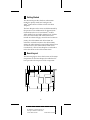
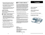
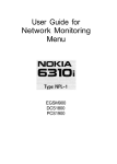
Installation Guide AHA-2740A Series EISA-to-Fast SCSI Host Adapters The AHA-2740A Series: AHA-2740A AHA-2742A AHA-2740A-Twin AHA-2742A-Twin R AA AAAA AA AAAAAAAA AAAAAAAA AAAAAAAA AAAAAAAA AAAAAAAA AAAAAAAA AAAAAAAA AAAAAAAA AAAAAAAA AAAAAAAA AAAAAAAA AAAAAAAA AAAAAA AA AA AA AHA-2740A Series Installation Guide AA AA AA AA AA AA Part Number: 511053-00, Rev. A AA AA AA AA AA AA Print Spec Number: 494619-00 AA AA AA AA AA AA Current Date: 2/7/96 ECN Date:1/30/96 AA AA AAAAAAAAAAAAAAAAAAAAAAAAAAAAAAAAAAAAAAAAAAAAAAAAAAAAAAA AA 1 Getting Started This document provides the basic information needed to quickly install and configure the AHA®-2740A Series of EISA-to-Fast SCSI Host Adapters. The host adapters in the series are differentiated by the presence of an additional SCSI channel (SCSI Channel B) on the two TwinChannel models: AHA-2740A-Twin and AHA-2742A-Twin. Furthermore, the AHA-2742A and AHA-2742A-Twin include an onboard floppy controller and connector. Jointly, the AHA-2740A and AHA-2742A are referred to in this document as the AHA-2740A/ 2742A; the AHA-2740A-Twin and AHA-2742A-Twin are referred to as the AHA-2740A/2742A-Twin. Cumulatively, all four host adapters are referred to in this document as the AHA-2740A Series. 2 Board Layout The following figure shows the location of the major components on the host adapter; the table that follows provides a description of each component. J1 U1 U2 J4 J3 U5 PIN 1 PIN 1 PIN 1 J2 J5 U9 U10 J6 1 A AAAA AAAA AAAA A AAAAAAAA AAAAAAAA AAAAAAAA AAAAAAAA AAAAAAAA AAAAAAAA AAAAAAAA AAAAAAAA AAAAAAAA AAAAAAAA AAAAAAAA AAAAAA AA A AA AHA-2740A Series Installation Guide A AA A AA A AA Part Number: 511053-00, Rev. A A AA A AA A AA Print Spec Number: 494619-00 A AA A AA A AA Current Date: 2/7/96 ECN Date: 1/30/96 A AA A AAAAAAAAAAAAAAAAAAAAAAAAAAAAAAAAAAAAAAAAAAAAAAAAAAAAAA AA Location Description J1 External LED Connector J2 Floppy Connector (AHA-2742A and AHA-2742A-Twin only) J3 SCSI Channel A Internal Connector J4 Floppy Enable Jumper (AHA-2742A and AHA-2742A-Twin only) J5 SCSI Channel B Internal Connector (AHA-2740A/2742A-Twin only) J6 SCSI Channel A External Connector U1 Floppy Controller (AHA-2742A and AHA-2742A-Twin only) U2 RAM U5 Host Adapter BIOS U9 AIC-7770 Bus Master SCSI Chip U10 AIC-701 Configuration Chip 3 Default Settings Your host adapter is already configured for the majority of EISA class computers. The following table lists the default settings for SCSI Channel A of your host adapter. If your host adapter is an AHA-2740A/2742A-Twin, the default settings for SCSI Channel B are the same as SCSI Channel A. Refer to Section 6, Configuring the Host Adapter, for information on changing any of these settings. Description Default Setting Interrupt Level IRQ 11 Level Bus Release Time 44 BCLKS Data FIFO Threshold 100% Host Adapter BIOS Base Address D8000h Host Adapter SCSI ID Device ID 7 SCSI Bus Parity Enabled SCSI Selection Timeout 256 ms SCSI Bus Reset at Power-on Enabled SCSI Bus Termination Enabled Primary Channel Selection (AHA-2740A/2742A-Twin only) Channel A Greater Than 1 GByte Support Enabled More Than Two Drives Support Enabled Removable Drive Support Support removable drive as boot device only Bootable CD-ROM Support Enabled Int 13h Extensions Support Enabled 2 A AAAA AAAA AAAA A AAAAAAAA AAAAAAAA AAAAAAAA AAAAAAAA AAAAAAAA AAAAAAAA AAAAAAAA AAAAAAAA AAAAAAAA AAAAAAAA AAAAAAAA AAAAAA AA A AA AHA-2740A Series Installation Guide A AA A AA A AA Part Number: 511053-00, Rev. A A AA A AA A AA Print Spec Number: 494619-00 A AA A AA A AA Current Date: 2/7/96 ECN Date: 1/30/96 A AA A AAAAAAAAAAAAAAAAAAAAAAAAAAAAAAAAAAAAAAAAAAAAAAAAAAAAAA AA The Onboard Floppy Controller (AHA-2742A and AHA-2742A-Twin only) ■ If your floppy diskette drives are already running under another controller, disable the onboard floppy controller by removing the jumper shunt on jumper J4. ■ To use the onboard floppy controller, leave the jumper shunt installed on jumper J4 and then disable your existing floppy controller; refer to your computer or floppy controller documentation. 4 Installing the Host Adapter Board Installation Caution: Turn OFF and disconnect power to the computer and external equipment. Always refer to your computer's documentation for instructions on removing the computer cover and adding option boards. 1 Remove the cover of your EISA computer to expose the EISA bus slots on the motherboard. 2 Locate an unused EISA slot that supports bus master operations (refer to the EISA computer documentation for details) and remove the corresponding slot cover. 3 Align and insert the host adapter in the EISA slot. Secure the host adapter in your computer. 5 Connecting Peripherals Connecting Cables SCSI devices are cabled together in a single continuous daisy chain of devices, called the SCSI bus. SCSI Channel A and SCSI Channel B (AHA-2740A/ 2742A-Twin only) can each accommodate a SCSI bus with up to seven SCSI devices connected. SCSI Channel A has both an internal and external connector. SCSI Channel B has an internal connector only. 3 A AAAA AAAA AAAA A AAAAAAAA AAAAAAAA AAAAAAAA AAAAAAAA AAAAAAAA AAAAAAAA AAAAAAAA AAAAAAAA AAAAAAAA AAAAAAAA AAAAAAAA AAAAAA AA A AA AHA-2740A Series Installation Guide A AA A AA A AA Part Number: 511053-00, Rev. A A AA A AA A AA Print Spec Number: 494619-00 A AA A AA A AA Current Date: 2/7/96 ECN Date: 1/30/96 A AA A AAAAAAAAAAAAAAAAAAAAAAAAAAAAAAAAAAAAAAAAAAAAAAAAAAAAAA AA Note: Only single-ended (non-differential) SCSI devices are supported by the AHA-2740A Series. Consult your SCSI device user documentation. Internal SCSI Cables The internal connectors for SCSI Channel A and SCSI Channel B (AHA-2740A/2742A-Twin only) use a 50-pin SCSI flat ribbon cable with a 50-pin header internal connector. Note: When connecting the 50-pin internal SCSI ribbon cable to both the host adapter and internal SCSI device(s), be sure to maintain pin-1 orientation throughout the bus. Pin 1 of the SCSI cable is designated by a colored stripe on one edge of the flat ribbon cable. Pin 1 of the host adapter or SCSI device connector is usually marked with a delta or arrow symbol (▲) on the connector. External SCSI Cables The external connector for SCSI Channel A uses a 50-pin shielded cable with a high-density external connector. External cable connectors are keyed and can only be plugged in one way; pin-1 orientation is automatic. Floppy Cables (AHA-2742A and AHA-2742A-Twin only) The floppy connector uses a 34-pin floppy ribbon cable with a 34-pin header connector. Be sure to maintain pin-1 orientation as previously described in Internal SCSI Cables. Termination on the SCSI Bus The first and last physical SCSI devices on the ends of the SCSI bus must have a set of resistors called terminators either installed or enabled. All other SCSI devices installed between the ends of the SCSI bus must have their terminators either removed or disabled. 4 A AAAA AAAA AAAA A AAAAAAAA AAAAAAAA AAAAAAAA AAAAAAAA AAAAAAAA AAAAAAAA AAAAAAAA AAAAAAAA AAAAAAAA AAAAAAAA AAAAAAAA AAAAAA AA A AA AHA-2740A Series Installation Guide A AA A AA A AA Part Number: 511053-00, Rev. A A AA A AA A AA Print Spec Number: 494619-00 A AA A AA A AA Current Date: 2/7/96 ECN Date: 1/30/96 A AA A AAAAAAAAAAAAAAAAAAAAAAAAAAAAAAAAAAAAAAAAAAAAAAAAAAAAAA AA Terminating the Host Adapter The factory installed bus terminators on the host adapter are enabled by default. Host adapter termination should be disabled if you attach SCSI devices to both internal and external connectors, since the host adapter would then be in the middle of the SCSI bus. The following table describes the three possible SCSI device and host adapter (AHA) configurations. Devices Connected To Host Adapter AHA Termination Internal devices only (AHA at end of cable) On/Enabled External devices only (AHA at end of cable) On/Enabled Internal and External devices (AHA in between) Off/Disabled Host adapter termination settings are software selectable only. To disable termination on the host adapter, refer to Section 6, Configuring the Host Adapter. Note: Any unused SCSI Channel (A or B) must have its termination enabled. If your host adapter is an AHA-2740A/2742A-Twin, host adapter termination for SCSI Channel B should normally be enabled. Terminating Other SCSI Devices Check the manufacturer's documentation to determine how to enable or disable SCSI bus termination on your SCSI device(s). SCSI ID Setting Each device on the SCSI bus must have a unique SCSI ID (0-7). Your host adapter has a default SCSI ID of 7. You only need to change SCSI IDs if there is a conflict. Refer to the 2740A Series User’s Guide for more detailed information on setting SCSI IDs. 6 Configuring the Host Adapter The EISA computer vendor normally supplies a bootable configuration diskette containing an EISA Configuration Utility (ECU). Depending on the ECU 5 A AAAA AAAA AAAA A AAAAAAAA AAAAAAAA AAAAAAAA AAAAAAAA AAAAAAAA AAAAAAAA AAAAAAAA AAAAAAAA AAAAAAAA AAAAAAAA AAAAAAAA AAAAAA AA A AA AHA-2740A Series Installation Guide A AA A AA A AA Part Number: 511053-00, Rev. A A AA A AA A AA Print Spec Number: 494619-00 A AA A AA A AA Current Date: 2/7/96 ECN Date: 1/30/96 A AA A AAAAAAAAAAAAAAAAAAAAAAAAAAAAAAAAAAAAAAAAAAAAAAAAAAAAAA AA supplied with your computer, host adapter configuration will vary. This section describes the basic steps involved in running the ECU. Running the ECU Place the configuration diskette in your floppy boot drive and reset the computer to boot from this diskette. Run the ECU as instructed by your EISA computer vendor. Copying Files The ECU typically allows you to select among a number of options, including copying new configuration files. Select this option to install the !adp7771.cfg and adp7770.ovl files from the host adapter diskette to the bootable configuration diskette. If the ECU does not provide such an option, you can use the DOS Copy command to copy these files to the bootable configuration diskette. Selecting the Host Adapter Once the files have been copied, run the option in the ECU that allows you to configure the EISA slot in which the host adapter is installed. Running this option will set up the default settings for the host adapter parameters. Configuring the Host Adapter Parameters This option allows you to change the host adapter parameter settings. ■ Interrupt Level– Defines the interrupt channel (IRQ) used by the host adapter. The default is IRQ 11 LEVEL. You may want to select a different IRQ for each host adapter to increase system performance. ■ Bus Release Time– Defines the length of time the host adapter will continue to transfer data after being pre-empted in Bus Master mode. The default is 44 BLCKS (bus clocks). If multiple bus master cards are installed in the system, you may want to lower the value to free the EISA bus sooner. 6 A AAAA AAAA AAAA A AAAAAAAA AAAAAAAA AAAAAAAA AAAAAAAA AAAAAAAA AAAAAAAA AAAAAAAA AAAAAAAA AAAAAAAA AAAAAAAA AAAAAAAA AAAAAA AA A AA AHA-2740A Series Installation Guide A AA A AA A AA Part Number: 511053-00, Rev. A A AA A AA A AA Print Spec Number: 494619-00 A AA A AA A AA Current Date: 2/7/96 ECN Date: 1/30/96 A AA A AAAAAAAAAAAAAAAAAAAAAAAAAAAAAAAAAAAAAAAAAAAAAAAAAAAAAA AA ■ Data FIFO Threshold– Defines the percentage used by the host adapter to manage its internal data FIFO. The default is 100%. ■ Host Adapter BIOS Base Address– Defines the base BIOS address, or disables the host adapter BIOS. The default is D8000h. When choosing the base address, verify that there is no conflict with other devices using the same address. Note: The BIOS must be enabled if you want the computer to boot from a SCSI hard drive attached to the host adapter. ■ Host Adapter SCSI ID– Defines the SCSI ID for the host adapter. The default SCSI ID is 7, which is the recommended setting. Each installed SCSI device must have a unique SCSI ID. Note: If any SCSI device is connected to the 50-pin internal SCSI connector, the host adapter SCSI ID must be assigned a value that ranges from 0 to 7. ■ SCSI Bus Parity Check– Enables or disables SCSI bus parity checking on the host adapter. The default is Enabled. Disable SCSI Bus Parity Check if any attached SCSI devices do no support parity checking. ■ SCSI Selection Timeout– Sets the time, in milliseconds, used by the host adapter during the SCSI Selection phase. Lowering the SCSI Selection Timeout will speed up SCSI bus scans considerably; however, before lowering this value, make sure that all the devices on the SCSI bus can respond to the shorter selection time. The default is 256 milliseconds. ■ SCSI Bus Reset at Power-on– Enables or disables a SCSI bus reset generated by the host adapter during its power-on initialization, and after a Hard Reset. The default is Enabled. 7 A AAAA AAAA AAAA A AAAAAAAA AAAAAAAA AAAAAAAA AAAAAAAA AAAAAAAA AAAAAAAA AAAAAAAA AAAAAAAA AAAAAAAA AAAAAAAA AAAAAAAA AAAAAA AA A AA AHA-2740A Series Installation Guide A AA A AA A AA Part Number: 511053-00, Rev. A A AA A AA A AA Print Spec Number: 494619-00 A AA A AA A AA Current Date: 2/7/96 ECN Date: 1/30/96 A AA A AAAAAAAAAAAAAAAAAAAAAAAAAAAAAAAAAAAAAAAAAAAAAAAAAAAAAA AA ■ SCSI Bus Termination–Enables or disables SCSI termination on the SCSI bus. The default is Enabled. Disable this parameter only if you attach SCSI devices to both internal and external connectors. ■ Primary Channel Selection (AHA-2740A/2742ATwin only)– Allows you to select which SCSI channel (A or B) the host adapter boots from. BIOS Configuration This option allows you to change the configuration of the host adapter BIOS. ■ Extended Translation for Drives >1GByte– Provides a mechanism under DOS for using a hard disk with a capacity greater than 1 GByte. Other operating systems do not need this mechanism. The following translation schemes are used: – Hard disks ≤ 1 GByte use a translation scheme of 64 heads, 32 sectors per track. – Hard disks ≥ 1 GByte use a translation scheme of 255 heads, 63 sectors per track. ■ Support for More Than Two Drives– Allows BIOS to recognize and control more than two SCSI hard disks without installing additional software drivers (supported by DOS 5.0 and above). If this option is enabled, up to eight hard disks can be attached to Int 13h. ■ Support Removable Disks as Fixed Disk– Allows you to use removable media disk drives without installing additional software drivers. The options are – Disable removable drive support – Support removable drive as boot device only – Support all removable drives Note: Support for removable drives means the BIOS treats a removable drive as if it were a fixed disk drive; it does not mean that the disk media can be removed during operation. 8 A AAAA AAAA AAAA A AAAAAAAA AAAAAAAA AAAAAAAA AAAAAAAA AAAAAAAA AAAAAAAA AAAAAAAA AAAAAAAA AAAAAAAA AAAAAAAA AAAAAAAA AAAAAA AA A AA AHA-2740A Series Installation Guide A AA A AA A AA Part Number: 511053-00, Rev. A A AA A AA A AA Print Spec Number: 494619-00 A AA A AA A AA Current Date: 2/7/96 ECN Date: 1/30/96 A AA A AAAAAAAAAAAAAAAAAAAAAAAAAAAAAAAAAAAAAAAAAAAAAAAAAAAAAA AA ■ Support for Bootable CD-ROM– allows you to boot up from a bootable CD-ROM. ■ Support for Int 13h Extensions– provides a mechanism to support disks with more than 1024 cylinders, and to add support for software control of drive locking for removable media. SCSI Device Configuration This option allows you to change certain parameters for each SCSI device connected to the host adapter. Select values for each setting as instructed on the screen's menu. ■ Error if Device Not Found– selects whether the operator will be notified if the BIOS is unable to find the device during the boot procedure. ■ Include in BIOS Scan– allows hard disks and removable media drives attached to the SCSI bus to be recognized by the host adapter BIOS and installed as devices on the computer without the need for device driver software. ■ Send Start Unit Command– is used for devices that require a command to start up after power on. Most devices do not require this. ■ Initiate Synch Negotiation– allows the host adapter to attempt to use the faster synchronous protocol for data transfers on the SCSI bus. If deselected, the transfer will be done asynchronously, unless a SCSI device itself requests synchronous negotiation. ■ Enable Disconnection– allows the host adapter and SCSI device to disconnect from the SCSI bus. When the SCSI device is ready to transfer data, then it can initiate a reconnect to the host adapter. ■ Maximum Sync Xfer Rate– allows selection of the highest data transfer speed that the host adapter will attempt with that device. The host adapter supports rates up to the Fast SCSI maximum of 10 MBytes/sec. When configuration of the SCSI devices is complete, save the configuration and exit the ECU. 9 A AAAA AAAA AAAA A AAAAAAAA AAAAAAAA AAAAAAAA AAAAAAAA AAAAAAAA AAAAAAAA AAAAAAAA AAAAAAAA AAAAAAAA AAAAAAAA AAAAAAAA AAAAAA AA A AA AHA-2740A Series Installation Guide A AA A AA A AA Part Number: 511053-00, Rev. A A AA A AA A AA Print Spec Number: 494619-00 A AA A AA A AA Current Date: 2/7/96 ECN Date: 1/30/96 A AA A AAAAAAAAAAAAAAAAAAAAAAAAAAAAAAAAAAAAAAAAAAAAAAAAAAAAAA AA Utilities The following SCSI utility is available with your host adapter: ■ Format Disk– accesses the Adaptec SCSI LowLevel Format utility. Most SCSI disk drives are preformatted, and do not need reformatting. Select Utilities from the ECU to access Format Disk. 7 Operating System Support DOS/Windows Under MS-DOS 5.0 or higher, up to eight SCSI hard disk drives can be connected to the host adapter without additional software. (Older versions of DOS support up to two hard disk drives.) Additional software is required to do the following: ■ Support more than two hard disk drives, under versions of DOS prior to MS-DOS 5.0. ■ Use devices other than hard disk drives such as SCSI tape, CD-ROM, scanners, etc. ■ Treat removable media devices as removable while your computer is running. Adaptec EZ-SCSI Adaptec EZ-SCSI for DOS/Windows, Windows 95, and Windows NT™ is included in this package. Use the menu-driven software to install drivers and configure your DOS/Windows operating system automatically. Other Operating Environments AHA-2740A Series host adapters support the Novell NetWare, OS/2, SCO, Novell Unixware operating systems. The Adaptec 7700 Family Manager Set is included in this package to enable you to install the appropriate driver for your system. Refer to the Adaptec 7700 Family Manager Set User’s Guide (also included) for detailed information. 10 A AAAA AAAA AAAA A AAAAAAAA AAAAAAAA AAAAAAAA AAAAAAAA AAAAAAAA AAAAAAAA AAAAAAAA AAAAAAAA AAAAAAAA AAAAAAAA AAAAAAAA AAAAAA AA A AA AHA-2740A Series Installation Guide A AA A AA A AA Part Number: 511053-00, Rev. A A AA A AA A AA Print Spec Number: 494619-00 A AA A AA A AA Current Date: 2/7/96 ECN Date: 1/30/96 A AA A AAAAAAAAAAAAAAAAAAAAAAAAAAAAAAAAAAAAAAAAAAAAAAAAAAAAAA AA 8 Troubleshooting Computer Will Not Boot From a SCSI Disk Drive If both SCSI and non-SCSI disk drives (e.g., IDE drives) are installed, then the non-SCSI disk drive is always the boot device. If there is no non-SCSI disk drive 1 Make sure your computer's CMOS Setup is set to No Drives Installed, as is required for SCSI host adapters. 2 Try enabling the BIOS Support Option as described in SCSI Device Configuration on page 9. 3 Make sure the SCSI hard disk drive SCSI ID is set to 0. The drive SCSI ID is normally set with jumpers or switches on the drive. Each SCSI device should be set to a unique SCSI ID. 4 Make sure the SCSI bus termination is set correctly. The ends of the SCSI bus must be terminated. 5 A low-level format of the SCSI hard disk may be necessary. Back up the data first, then run the Format utility accessible through the ECU. Multiple Host Adapters Make sure that each host adapter is set to a separate BIOS address. Or, disable the BIOS on all but one of the host adapters. 11 A AAAA AAAA AAAA A AAAAAAAA AAAAAAAA AAAAAAAA AAAAAAAA AAAAAAAA AAAAAAAA AAAAAAAA AAAAAAAA AAAAAAAA AAAAAAAA AAAAAAAA AAAAAA AA A AA AHA-2740A Series Installation Guide A AA A AA A AA Part Number: 511053-00, Rev. A A AA A AA A AA Print Spec Number: 494619-00 A AA A AA A AA Current Date: 2/7/96 ECN Date: 1/30/96 A AA A AAAAAAAAAAAAAAAAAAAAAAAAAAAAAAAAAAAAAAAAAAAAAAAAAAAAAA AA 9 Adaptec Customer Support Services If you have questions about installing or using your Adaptec product, check this document first—you will find answers to most of your questions here. If you need further assistance, please contact us. We offer the following support and information services: ■ For technical support, for information about the Adaptec Electronic Bulletin Board Service (BBS) and the File Transfer Protocol (FTP) and World Wide Web (WWW) Servers, and for access to the Interactive Fax system, call 800-959-SCSI (7274) or 408-945-2550, 24 hours a day, 7 days a week. To speak with a product support representative, call 408-934-SCSI (7274), Monday through Friday, 6:00 A.M. to 5:00 P .M., Pacific Time; after these hours, on weekends, and on holidays, product support is also available for a fee at 800-416-8066. – The Adaptec BBS provides answers to commonly asked questions and information on software upgrades and other topics. The BBS is available 24 hours a day, 7 days a week, at 408-945-7727; 1200/2400/9600/14,400/28,800 baud, 8 data bits, 1 stop bit, no parity. – The Adaptec FTP and WWW Servers provide product literature, answers to commonly asked questions, and information on software upgrades and other topics. The FTP and WWW Servers are available from the Internet 24 hours a day, 7 days a week, at ftp.adaptec.com and http://www.adaptec.com. – The Adaptec Interactive Fax system provides product literature, answers to commonly asked questions, and current information about Adaptec products and services. The Adaptec Interactive Fax system is available 23 hours a day, 7 days a week. The Fax system is out of service 1 hour each day. You can call this service directly at 408-957-7150. ■ For sales information, call 800-959-SCSI (7274) or 408-945-2550, Monday through Friday, 6:00 A.M. to 5:00 P.M., Pacific Time. ■ To order Adaptec software and cables, call 800-442-SCSI (7274) or 408-957-SCSI (7274), Monday through Friday, 6:00 A.M. to 5:00 P.M., Pacific Time. ■ To request additional documentation for Adaptec products, call 800-934-2766 or 510-732-3829, Monday through Friday, 6:00 A.M . to 5:00 P.M., Pacific Time. 12 A AAAA AAAA AAAA A AAAAAAAA AAAAAAAA AAAAAAAA AAAAAAAA AAAAAAAA AAAAAAAA AAAAAAAA AAAAAAAA AAAAAAAA AAAAAAAA AAAAAAAA AAAAAA AA A AA AHA-2740A Series Installation Guide A AA A AA A AA Part Number: 511053-00, Rev. A A AA A AA A AA Print Spec Number: 494619-00 A AA A AA A AA Current Date: 2/7/96 ECN Date: 1/30/96 A AA A AAAAAAAAAAAAAAAAAAAAAAAAAAAAAAAAAAAAAAAAAAAAAAAAAAAAAA AA FCC Compliance Statement NOTE: This equipment has been tested and found to comply with the limits for a Class B digital device, pursuant to Part 15 of the FCC rules. These limits are designed to provide reasonable protection against harmful interference in residential installations. This equipment generates, uses, and can radiate radio frequency energy, and if not installed and used in accordance with the instructions, may cause harmful interference to radio communications. However, there is no guarantee that interference will not occur in a particular installation. If this equipment does cause interference to radio or television equipment reception, which can be determined by turning the equipment off and on, the user is encouraged to try to correct the interference by one or more of the following measures: • • • • Reorient or relocate the receiving antenna Move the equipment away from the receiver Plug the equipment into an outlet on a circuit different from that to which the receiver is powered If necessary, the user should consult the dealer or an experienced radio/ television technician for additional suggestions CAUTION: Only equipment certified to comply with Class B (computer input/output devices, terminals, printers, etc.) should be attached to this equipment, and must have shielded interface cables. Finally, any changes or modifications to the equipment by the user not expressly approved by the grantee or manufacturer could void the user ’s authority to operate such equipment. Each host adapter is equipped with an FCC compliance label that shows only the FCC identification number. The full text of the associated label follows: This device complies with part 15 of the FCC rules. Operation is subject to the following two conditions: (1) this device may not cause harmful interference and (2) this device must accept any interference received, including interference that may cause undesired operation. Adaptec, Inc. 691 South Milpitas Blvd. Milpitas, CA 95035 Copyright 1993, 1994, 1995,1996, Adaptec, Inc. All rights reserved. Adaptec, the Adaptec logo, AHA, AIC, EZ-SCSI and TwinChannel are trademarks of Adaptec, Inc. which may be registered in some jurisdictions. Windows NT is a trademark, and Windows and Windows 95 are registered trademarks of Microsoft Corporation in the U.S. and other countries used under license. All other trademarks are owned by their respective owners. Printed in Singapore Stock No.: 511053-00, Rev. A JW 1/96 Information subject to change without notice. 13 A AAAA AAAA AAAA A AAAAAAAA AAAAAAAA AAAAAAAA AAAAAAAA AAAAAAAA AAAAAAAA AAAAAAAA AAAAAAAA AAAAAAAA AAAAAAAA AAAAAAAA AAAAAA AA A AA AHA-2740A Series Installation Guide A AA A AA A AA Part Number: 511053-00, Rev. A A AA A AA A AA Print Spec Number: 494619-00 A AA A AA A AA Current Date: 2/7/96 ECN Date: 1/30/96 A AA A AAAAAAAAAAAAAAAAAAAAAAAAAAAAAAAAAAAAAAAAAAAAAAAAAAAAAA AA