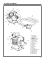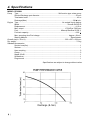
1
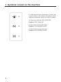
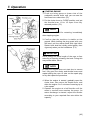
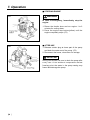
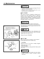
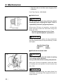
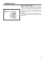
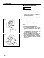
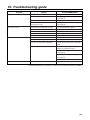
T1056-93510 (904)
OPERATOR’S MANUAL
WATER PUMP
PE2500H
WARNING
• Before using our water pumps, please
read this manual carefully to understand
the proper use of your unit.
• Keep this manual handy.
SAFETY FIRST
Instructions contained in warnings within this
manual marked with a
symbol concern
critical points which must be taken into
consideration to prevent possible serious
bodily injury, and for this reason you are
requested to read all such instructions
carefully and follow them without fail.
■ WARNINGS IN THE MANUAL
WARNING
This mark indicates instructions which must be
followed in order to prevent accidents which could
lead to serious bodily injury or death.
IMPORTANT
This mark indicates instructions which must be
followed, or it leads to mechanical failure,
breakdown, or damage.
NOTE
This mark indicates hints or directions useful in the
use of the product.
1.
2.
3.
4.
5.
6.
7.
8.
9.
10.
CONTENTS
Symbols carved on the machine ……………4
For safe operation ……………………………5
Parts location …………………………………7
Specifications …………………………………8
Fuel ……………………………………………9
Set up …………………………………………11
Operation ……………………………………12
Maintenance …………………………………15
Storage ………………………………………18
Troubleshooting guide ………………………19
1. Symbols carved on the machine
For safe operation and maintenance, symbols are
carved in relief on the machine. According to these
indications, please be careful not to take a mistake.
(a) The port to refuel the "MIX GASOLINE"
Position: FUEL TANK CAP
(b) The direction to close the choke
Position: AIR CLEANER COVER
(c) The direction to open the choke
Position: AIR CLEANER COVER
❲4 ❳
2. For safe operation
• Before operating the machine, be sure to
read through this manual carefully and
follow proper operating instructions.
• Never allow children or anyone unable to
fully understand the instructions given in
the manual to use the machine.
■ NOTES FOR OPERATION
• Before using the machine, read this manual
carefully to understand it’s function and safety
instructions for operation.
• Do not apply this pump for other than fresh
water or agricultural water.
Those cannot be applied are:
Drinking Water, Muddy Water, Sea Water,
Flammable Fluids(Such as Kerosene, Diesel Oil,
Gasoline, or Heavy Oil), Chemical Agents, Acid
or Alkaline Fluids, etc.
• Engine exhaust gas contain hazardous carbon
monoxide(CO). Avoid operating this pump
indoors, in green house, tunnel, etc. where
ventilation is imperfect.
• Do not place any flammable object such as
straw, withered leaves, rubbish, oily wiping cloth,
etc. around the pump in operation.
• Engine of this machine runs on the mixed fuel
that contain highly flammable gasoline. Never
refuel nor store the fuel where there is an
incinerator, burner, open fire, stove, electric
spark, welding arc spatter, etc.
• Never smoke while refueling. It is absolutely
hazardous.
• Prior to refueling, be sure to stop the engine and
confirm that there is no fire around.
• Spilled fuel shall be completely wiped away with
cloths, etc. before restarting the engine.
• Securely tighten both fuel caps for the fuel tank
and the fuel container after refueling.
• Do not transport the pump for a long time on
rough roads with fuel in the tank. Fuel cap may
become loose with vibration and cause fuel
leakage.
• Keep children and pets away from where
starting or operating the engine.
❲5 ❳
2. For safe operation
• Do not touch the spark plug or the plug wire
while the engine is in operation. They may cause
an electric shock.
• Do not touch metallic parts such as the muffler,
spark plug, etc. with bare hands during the
operation of engine or immediately after a stop.
They may be very hot and cause burns.
• Apply isolation measures to keep children or
infants away from the pump so that you can
operate it in safe area.
• Temperature of the pumping up water shall be in
between 5°C to 60°C. Otherwise, the pump may
be damaged.
• Avoid idle pump operation(operation with no
water in the pump). This may cause pump
damage.
• Be sure to use only attached suction hose or an
equivalent “water suction hose” as an water inlet
hose.
• Make sure to couplings and clumps(attached to
this kit) when connecting the suction and
discharge hoses to the pump.
• The engine shall be stopped to transfer pump.
■ NOTES FOR MAINTENANCE
• In order to maintain your machine in proper
condition, perform regular checking and
maintenance described in this manual. In case
you need a maintenance service or replacing of
component not listed in this manual, consult with
the shop of your purchase or nearby ZENOAH
service dealers.
• Be sure to stop the engine before any inspection
or maintenance procedure.
• Never disassemble nor modify your machine.
This may cause damage of machine during
operation and end up with serious accidents.
• Always use ZENOAH genuine parts or ZENOAH
specified parts for replacement.
• Keep this manual handy so that you may refer
back to it later whenever any doubt arises.
• When you sell or lend this machine to others,
never forget to attach this operator’s manual
together.
❲6 ❳
3. Parts Location
1. Air cleaner
2. Throttle lever
3. Spark plug
4. Handle
5. Self-suction plug
6. Discharge port
7. Suction port
8. Hose coupling
9. Clump
10. Suction hose
11. Strainer
12. Clump
13. Drain plug
14. Base
15. Fuel tank
16. Engine stop button
17. Fuel tank cap
18. Starter knob
19. Exhaust vent
20. Engine cover
❲7 ❳
4. Specifications
MODEL PE2500H
Pump Type ················································································· Self suction type volute pump
Suction/Discharge port diameter·········································································· 25 mm
Total water head ·····································································································45 m
Discharge(Max.) ·····························································································130 / min.
Engine Type ························································································· Air-cooled 2cycle engine
Model ·································································································· Zenoah G43LH-D
Displacement······································································································· 41.5 cc
Max. output···················································································· 1.75(HP)at 7200 rpm
Fuel ······················································································· Mixture(Gasoline 25:Oil 1)
Fuel tank capacity ································································································ 0.95
Max. operating time/Fuel charge ··························································· Approx. 40 min.
Starting Method···························································································Recoil starter
Overall size(L x W x H) ··················································································320 x 257 x 334 mm
Dry weight·····························································································································7.5 kg
Standard Accessories
Suction hose(3m) ·········································································································· 1
Strainer·························································································································· 1
Hose coupling ··············································································································· 3
Clump·····························································································································3
Nipple 25x20 ··················································································································1
Screwdriver ····················································································································1
Plug wrench ·················································································································· 1
Specifications are subject to change without notice.
❲8 ❳
5. Fuel
WARNING
• Gasoline is very flammable. Avoid smoking
or bringing any flame or sparks near fuel.
Make sure to stop the engine and allow it
cool before refueling the unit. Select outdoor
bare ground for fueling and move at least
3m(10ft) away from the fueling point before
starting the engine.
• The RedMax engines are lubricated by oil
specially formulated for air-cooled 2-cycle
gasoline engine use. If RedMax oil is not
available, use an anti-oxidant added quality oil
expressly labeled for air-cooled 2-cycle engine
use.(FC GRADE OIL)
RECOMMENDED MIXING RATIO
GASOLINE 25:OIL 1
25:1 MIXING CHART
GASOLINE Liter 1
2
3
4
5
2-CYCLE OIL ml 40 80 120 160 200
• Exhaust emission are controlled by the
fundamental engine parameters and
components(eq., carburation, ignition timing
and port timing) without addition of any
major hardware or the introduction of an
inert material during combustion.
• These engines are certified to operate on
unleaded gasoline.
• Make sure to use gasoline with a minimum
octane number of 90 ROZ(USA/Canada : pump
octane min.87)
• Unleaded gasoline is recommended to reduce
the contamination of the air for the sake of your
health and the environment.
• Poor quality gasolines or oils may damage
sealing rings, fuel lines or fuel tank of the
engine.
■ HOW TO MIX FUEL
1. Measure out the quantities of gasoline and oil to
be mixed.
2. Put some of the gasoline into a clean, approved
fuel container.
3. Pour in all of the oil and agitate well.
4. Pour in the rest of gasoline and agitate again for
at least one minute.
5. Put a clear indication on the outside of the
container to avoid mixing up with gasoline or
❲9 ❳
5. Fuel
other containers.
6. Indicate the contents on outside of container for
easy identification.
■ FUELING THE UNIT
1. Untwist and remove the fuel cap. Rest the cap
on a dustless place.
2. Put fuel into the fuel tank to 80% of the full
capacity.
3. Fasten the fuel cap securely and wipe up any
fuel spillage around the unit.
WARNING
1. Select bare ground for fueling.
2. Move at least 10 feet(3 meters) away from the
fueling point before starting the engine.
3. Stop the engine before refueling the unit.
FOR YOUR ENGINE LIFE, AVOID;
1. FUEL WITH NO OIL(RAW GASOLINE) – It will
cause severe damage to the internal engine
parts very quickly.
2. GASOHOL – It can cause deterioration of rubber
and/or plastic parts and disruption of engine
lubrication.
3. OIL FOR 4-CYCLE ENGINE USE or WATER
COOLED 2-CYCLE ENGINE USE – It can
cause spark plug fouling, exhaust port blocking,
or piston ring sticking.
4. Mixed fuels which have been left unused for
a period of one month or more may clog the
carburetor and result in the engine failing to
operate properly.
❲ 10 ❳
6. Set up
IMPORTANT
• As a suction hose, be sure to use attached
suction hose(nominal diameter 25mm x 3m) or
an equivalent ‘water suction hose’ only.
• Securely connect hoses with attached hose
couplings and clumps.
• If the suction hose connection is loose, or a
packing in hose coupling has been lost or
damaged, air may be sucked into the pump and
interrupt water suction (air lock).
• A strainer shall be placed so that it does not
appear above water level nor suck bottom sand
and mud.
F1
1. Place your pump at nearby water resource
horizontally.
2. Insert attached hose couplings to the suction
hose and discharge hose and tighten them with
clumps.
3. After checking the packing of each hose
coupling, connect the suction hose to a suction
port and the discharge hose to a discharge port.
NOTE
Discharge port angle can be changed to 3 different
directions. Adjust to your operating condition.
F2
4. Submerge the suction hose strainer in the water.
5. Lay the discharge hose where necessary.
Arrange protective covers if the hose can be
disturbed by foot steps of others.
6. Remove self-suction plug and top up the pump
with water. (F1)
7. Fill up fuel tank with fuel and tighten the tank cap
securely. (F2)
❲ 11 ❳
7. Operation
WARNING
• Fuel(Gasoline) is highly flammable and
incorrect handling will cause fire accident.
Strictly avoid smoking or fire during mixing
or supplying the fuel.
• Be sure to stop the engine and allow it to be
cooled before refueling.
• Spilled fuel shall be completely wiped away
with wiping cloth, etc. before restarting the
engine.
• Do not leave any flammable object around
engine exhaust port.
WARNING
Before starting the engine, check if there is
anything that must not be wet near the discharge
hose tip. Give warning to nearby people of starting
water discharge.
IMPORTANT
• Idle operation with no water in the pump may
cause pump damage. Before starting the engine,
check if the pump is filled with selfsuction(priming) water. In case the suction
strainer comes out of the water level during
operation, immediately reduce the engine speed
and stop the operation.
• Confirm that the suction hose connection is not
too loose. Loose connection may result in no
suction water.
• In case the discharge hose is clogged or a valve
connected to the discharge hose is closed, the
pump may not suck water.
• Stepping on the discharge hose or sudden
closure of the discharge valve may create
instantaneous high pressure in the pump and
result in pump damage(Water Hammer Effect).
Arrange protective covers if the hose can be
disturbed by others stepping on, and avoid
closing the valve rapidly.
❲ 12 ❳
7. Operation
F3
■ STARTING ENGINE
1. Push a priming pump at lower side of the
carburetor several times until you can see the
fuel flows into a clear tube. (F3)
2. Put the choke lever to CLOSE position, and set
the throttle lever 1/3 to 1/2 open from fully
returned position. (F3)
NOTE
Choke lever to OPEN for restarting immediately
after stopping engine.
F4
3. Confirm that the machine is stable on the
ground. While holding the plug guard with your
left hand, pull the starter knob with right hand.
Starter knob shall be initially pulled gently, then
vigorously when you feel resistance. (F4)
IMPORTANT
Avoid pulling out entire length of the rope or free
returning of rope by releasing the knob. Doing this
may cause starter failure.
NOTE
In case the engine does not start due to excess
fuel, fully open the choke and throttle levers and
repeat pulling the rope. Or take out the spark plug
to dry and repeat the procedure.
4. When the engine is started, gradually open the
choke lever, also return the throttle lever, and
allow the engine 2 to 3 minutes of warming up at
a low speed.
5. Operate the engine at a half throttle until the
water in suction hose reaches the pump. As
water discharge is started, adjust the throttle
according to your required flow rate within the
capacity.
❲ 13 ❳
7. Operation
■ STOPPING ENGINE
F5
WARNING
In case of emergency, immediately stop the
engine.
1. Return the throttle lever and run engine 1 to 2
minutes for cooling down.
2. Press the engine stop button(yellow) until the
engine completely stops. (F5)
F6
■ AFTER USE
1. Release a drain plug at lower part of the pump
and drain the water out of the pump. (F6)
2. Disconnect the hoses, clean them for storage.
IMPORTANT
During cold climate, be sure to drain the pump after
every use. At an ambient temperature below
freezing point, the water in the pump casing may
freeze and damage the pump.
❲ 14 ❳
8. Maintenance
WARNING
• Be sure to stop the engine and keep off fire for
inspection and maintenance.
• Always use our genuine parts/oils or our
specified goods for replacement.
■ AIR CLEANER
After every 25 hours of operation, release the air
cleaner cover and remove dusts. In case the
element is dirty, carefully wash it with warm water
containing neutral detergent. Completely dry before
refitting the element. If the element is deformed or
damaged, replace it with new one.
IMPORTANT
F7
Clogged air cleaner spoils engine performance.
Also, operation with no element or with deformed or
damaged element causes irregular wear outs of the
engine mechanism.
NOTE
To remove the air cleaner cover, disengage a clip
on the light side of the cover first. When recovering,
engage right side clip first. (F7)
Element Part No.1750-82020
F8
■ FUEL TANK
After every 25 hours of operation, check inside of
the tank and remove dirt or water if any.
• Fuel Filter
Remove any dirt. If the filter is badly clogged,
replace with new one. (F8)
• Fuel Tank Cap
Check the air vent for choking with dirt. Remove dirt
if any. (F8)
IMPORTANT
• Clogged fuel filter and choked vent valve reduce
engine speed or cause unstable engine
revolution.
❲ 15 ❳
8. Maintenance
• Operation with no fuel filter cause clogging of the
carburetor.
Fuel Filter Part No. 3302-85400
■ SPARK PLUG
F9
WARNING
Do not touch the spark plug with bare hands
immediately after stopping the engine. There is
a possibility of burns by high temperature.
After every 25 hours of operation, remove the
spark plug and clean the electrode using wire
brush, etc. (F9)
Recommended plug gap is 0.6~0.7mm.
Use the specified plug for replacement.
IMPORTANT
Excess fuel and poor quality oil may contaminate
the plug electrode and end up with difficulty to start
the engine.
Specified Spark Plug
Champion : CJ-6Y
NGK
: BPM7A
■ INTAKE AIR COOLING VENT
F10
WARNING
Never insert anything into the intake air cooling
vent during engine operation.
It may crush with internal rotating components.
After every 25 hours of operation, check the intake
air cooling vent and cylinder fins and remove any
dirt. (F10)
IMPORTANT
Clogging of the air cooling vent and cylinder fins
may cause overheating of the engine and result in
engine failures.
❲ 16 ❳
8. Maintenance
F11
■ ADJUSTING IDLE SPEED
Engine idle speed is already adjusted at shipping.
However, if the engine stalls due to too low engine
speed when fully returning the throttle lever or if
you feel it to be too high, adjust the speed. Idle
adjusting screw is on the upper part of the
carburetor.
Engine speed increases with clockwise turning of
the screw and decreases with counterclockwise
turning. (F11)
❲ 17 ❳
9. Storage
■ STORING FOR LONG PERIOD
IMPORTANT
F12
• To stop using your machine for a long
period, drain fuel from the fuel tank and
the carburetor before storing it. Fuel left
behind inside there for long period may
clog the carburetor and cause engine
troubles as no starting of engine or
reduced engine output.
• Leave the fuel cap loose during storage.
Over tightening may cause deform of
packing.
In case the pump is not used for more than 1
month, apply following maintenance
procedures before storing it in dry, clean
place:
F13
❲ 18 ❳
1. Drain fuel from the fuel tank. (F12)
2. Fill the pump with water and start the
engine at a low speed until it stops with no
fuel.
3. Remove the spark plug and pour 1~2cc of
2 cycle engine oil into the cylinder, and
pull the starter rope for 2~3 times.
4. Refit the spark plug. Pull the starter rope
and return it when you feel a resistance.
5. Drain water from the pump completely,
and wipe off water on the pump using dry
cloth. (F13)
10. Troubleshooting guide
STATUS
Engine does not start
CAUSE
Faulty fuel(incorrect, degraded)
Excess fuel sucked
No suction of water
Discharge water flow rate too small
Exhaust muffler choked
Spark plug electrode dirty, short or
disconnected circuit
Insufficient self-sucking water in pump
Loose connection of suction hose
Faulty packing in suction hose connection
Suction hose crack breakage
Folded discharge hose, closed valve
Clogged suction strainer
Pump position too high from water level
Too far or too high place to discharge
Engine output too low
Water leakage from pump
Loosen assembly bolts
COUNTERMEASURE
Change with proper fuel(see Page 9)
Open choke and repeat pulling rope
(see Page 13)
cleaning
Cleaning of electrode or replace plug
(see Page 16)
Top up with water(see Page 11)
Tighten securely not to suck air
Replace with proper one(ask for service)
Replace with proper one
Extend and stretch hose, open valve
Cleaning of suction strainer
Lowering pump height to water level
Secure water resource near to discharge
place
Check fuel degrading, water ingress.
Replace if needed(see Page 9)
Check air filter clogging, cleaning
(see Page 15)
Check fuel filter clogging, cleaning
(see Page 15)
Carburetor adjustment
Tightening of bolts
If further assistance is needed, contact your authorized service dealer.
❲ 19 ❳
Warranty certificate
Komatsu Zenoah Co.
The Komatsu Zenoah product model No.PE2500H is covered by a Warranty of 6 months from
the following date of purchase. In the case of professional machine used for professional work,
such machines are covered by a Warranty of 3 months.
We undertake according to our ability to supply free of charge all parts found defective at origin
except in case where the defect can be traced back to either wrong manipulation or normal wear.
Such excepted parts are not covered by this Warranty. Please address your complaints to the
following address.
2-142-1 Sakuragaoka, Higashiyamato, Tokyo, 207-8788 Japan