1
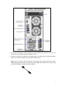
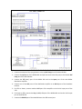
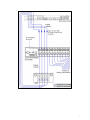
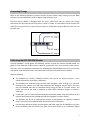
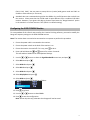
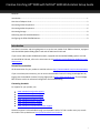
Creative Finishing HP® Z800 with NVIDIA® 6000 Workstation Setup Guide
Contents
Introduction .................................................................................................................................................. 1
Overview of Adapter Cards ........................................................................................................................... 2
Connecting Video Components .................................................................................................................... 4
Connecting Audio Components .................................................................................................................... 6
Connecting Storage ....................................................................................................................................... 8
Calibrating the EIZO CG245W Monitor ......................................................................................................... 8
Configuring the EIZO CG245W Monitor........................................................................................................ 9
Introduction
Use these instructions and wiring diagrams to set up the new model of HP Z800 workstation, equipped
with the NVIDIA Quadro 6000 graphics card and the AJA Kona 3G VIO card.
If you have an older model HP Z800 workstation, equipped with the NVIDIA FX5800 graphics card and
the AJA OEM-2K VIO card, refer to the instructions in the Installation and Configuration Guide for Linux®
Workstations.
Related Documentation
All documentation for your product is available online at http://www.autodesk.com/me-documentation.
If you are a subscription customer, you can access the Autodesk Creative Finishing Knowledge Base by
logging into the Autodesk Creative Finishing Edge portal at https://edge.autodesk.com. The Knowledge
Base contains articles on advanced configuration and troubleshooting.
Contacting Autodesk
For support for your product, see:
www.autodesk.com/smoke-support
www.autodesk.com/flame-support
www.autodesk.com/lustre-support
www.autodesk.com/inferno-support
www.autodesk.com/flint-support
www.autodesk.com/flare-support
www.autodesk.com/backdraftconform-support
Customer support is also available through your Autodesk reseller. To find a reseller near you, consult
the reseller look-up database at http://www.autodesk.com/resellers.
1
Overview of Adapter Cards
The following illustration provides an overview of the adapter cards in the Z800 workstation.
Note: The Mellanox InfiniBand/10-GigE adapter in slot 7 is optional.
Connecting Peripherals
The following diagram illustrates how to connect peripherals, such as the graphics monitor, keyboard,
mouse, Wacom® Intuos® pen tablet, and house network, to the HP Z800 workstation.
It is recommended to connect all hardware peripherals as illustrated before booting the workstation for
the first time.
2
1. Use the short DVI cable to connect the DVI port of the NVIDIA Quadro graphics card in slot 2 to
the DVI port of the NVIDIA Quadro SDI adapter in slot 6.
2. Connect the Display Port extender to the display port 1 (the outer port) of the NVIDIA Quadro
graphics card and to the display port of the EIZO CG245 monitor.
Note: If you are using an older EIZO monitor, such as the CG241, connect the DP port of the
NVIDIA Quadro graphics card to the Avenview FO-DVI-25MM DVI extender of the monitor using
the DP to DVI adapter included with the workstation.
3
Make sure to also connect the supplied DVI extender power adapter to the DVI extender cable,
otherwise the monitor will not display an image.
3. Connect the keyboard, mouse and graphics tablet directly to the USB ports of the workstation,
or to an USB extender.
4. Connect the bottom on-board Ethernet port of the workstation (port 0) to your facility network.
5. If configuring a Lustre workstation, connect the Ethernet cable coming from the Autodesk
Control Surface Ethernet switch to the top on-board Ethernet port of the workstation.
6. If configuring a Lustre workstation, connect the USB cable coming from the central panel of the
Autodesk Control Surface to an USB port on the workstation or to the USB extender.
7. Optional: Connect one port of the InfiniBand adapter to the InfiniBand switch.
Connecting Video Components
The following diagram illustrates how to connect the video hardware components included in your
shipment.
The only video hardware you must provide are a sync generator, VTR, HD/SDI-ready broadcast monitor
and patch panel (if desired).
4
1. Connect the output of the sync generator to the top Ref Loop port of the AJA K3G-Box.
2. Connect the Input port of the NVIDIA SDI card (the one next to the DVI port) to the bottom Ref
Loop port of the AJA K3G-Box.
3. Connect the Fill (outer) port of the NVIDIA SDI card to the Input port of the AJA HD5DA
distribution amplifier.
4. Connect one of the OUT ports of the distribution amplifier to an SDI IN port of the broadcast
monitor.
5. For RTD or Stereo, connect another OUT port of the amplifier to the Link A input port of the
VTR.
6. For Stereo or RTD, connect the Key (middle) SDI port of the NVIDIA SDI card to the Link B input
port of the RTD VTR.
7. Connect the RS-422 port of the AJA K3G-Box to the VTR control port.
5
8. If not using RTD, connect SDI OUT A, SDI OUT B, SDI IN A and SDI IN B ports of the VTR to the
SDI1, SDI2, SDI3 and SDI4 ports on the front of the AJA K3G-Box.
9. Connect the SDI IN 1/A, SDI IN 2/B, SDI OUT 1/A and SDI OUT 2/B plugs of the AJA cable to the
SDI1, SDI2, SDI3 and SDI4 ports of the AJA Kona 3G card.
10. Connect the SDI IN 1/A, SDI IN 2/B, SDI OUT 1/A and SDI OUT 2/B plugs on the other end of the
AJA cable to the SDI1, SDI2, SDI3 and SDI4 ports on the back of the AJA K3G-Box, as illustrated.
11. Connect the AJA control cable to the AJA Kona card and to the corresponding port on the back
of the AJA K3G-Box.
Note : AJA Kona 3G is shipping with up to date firmware. Firmware update procedure will be
published when new certified firmware becomes available.
Connecting Audio Components
Your application uses the Discreet Native Audio subsystem. Discreet Native Audio uses the following
hardware components, shipped with your system.
Lucid ADA 88192 Audio Converter - Converts signals between the workstation and all digital or
analog audio I/O devices.
AJA K3G-Box Balanced Audio breakout box and AJA Kona 3G adapter card - The Balanced
Audio breakout box is the audio component of the AJA breakout box. It provides connections for
audio I/O. This breakout box connects to the AJA Kona 3G adapter on your workstation. The
Kona 3G adapter provides real-time input and output of uncompressed SD and HD video signals
as well as audio data at 24-bit resolution. The Kona 3G adapter handles balanced AES/EBU audio
signals from the Balanced Audio breakout box.
The following diagram illustrates how to connect the Discreet Native Audio hardware components to
the AJA breakout box.
6
7
Connecting Storage
Refer to the following diagram to connect the fibre channel cables (loops) coming from your RAID
controllers to the workstation’s ATTO FC adapter card, located in slot 4.
The fibre channel adapter is equipped with four ports, called loops. You can connect the storage
enclosure to the fibre channel card using either 2 loops or 4 loops. A 2-loop device can be connected to
either the inner pair of ports or the outer pair of ports. A 4-loop device requires both the inner pair and
the outer pair.
Calibrating the EIZO CG245W Monitor
The EIZO CG245W is a wide-gamut self-calibrating monitor. As with the previous CG241W model, the
gamut is much wider than a video monitor. However, you may also set it up to emulate a video monitor.
The Lustre Color user guide has instructions for calibrating the EIZO CG241W monitor for both (native)
wide-gamut mode and video mode. These instructions may also be followed for the CG245W.
Note the following:
The CG245W has a built-in calibration feature, thus you do not need to connect a color
measurement device to perform a calibration.
The CG241W was calibrated using the EIZO Color Navigator utility running on a computer
attached to the monitor via a USB cable. Although Color Navigator may be used in the same
way, the CG245W may also be calibrated entirely using the built-in on-screen menus. This
means that you do not need a computer to either define calibration targets or execute a
calibration.
Furthermore, you may switch between wide-gamut and video modes using the M button on the
monitor bezel (whereas the CG241W required Color Navigator to switch modes).
The CG245W may be set to automatically perform a self-calibration at regularly scheduled
times. Please consult the EIZO CG245W user guide for more information.
Use the same calibration targets for wide-gamut and video mode for the CG245W as are given
for the CG241W in the Lustre Color user guide. The monitor allows up to 3 calibration targets
8
(CAL1, CAL2, CAL3). You may want to setup CAL1 to (native) wide-gamut mode and CAL2 to
emulate a video monitor (or vice versa).
Autodesk does not recommend using either the sRGB or the rec709 presets that are built into
the monitor. Please note that the rec709 mode is quite different from a traditional HD video
monitor. However, if you ignore this advice, please at least leave the "Range Extension" option
in the monitor's on-screen menus at "Off" (which is its default setting).
Configuring the EIZO CG245W Monitor
To accommodate all the refresh rates used by the Creative Finishing software, you need to modify the
Range of Frequency settings on the EIZO CG245W monitor.
Note: The monitor does not need to be connected to a computer to perform this procedure.
1. Ensure the power cable is connected to the monitor.
2. Ensure the power switch on the back of the monitor is on.
3. Ensure the monitor is turned off. If it is not, press
to do so.
4. Press and hold down the
and
buttons for at least 2 seconds.
This will enable a hidden menu called Optional Settings.
5. Use the
and
buttons to select the Signal Bandwidth menu item, and press
6. Select DVI-1 and press
.
7. Select Wide-3 and press
8. Select DVI-2 and press
9. Select Wide-3 and press
.
.
.
.
10. Select DisplayPort and press
.
11. Select Wide and press .
At this point, the settings should be as follows:
12. Press
13. Use the
to go back.
and
buttons to select Finish.
14. Press
to save the configuration.
Note: Do not skip this step; otherwise the changes will not be saved.
9
15. The monitor automatically turns off and back on, and the text “Now adjusting” is displayed in
the lower left corner of the screen:
16. After a few seconds the monitor returns to normal state and is ready to use.
Autodesk, Backburner, Backdraft, Burn, Flame, Flare, Flint, Inferno, Lustre, Smoke, Wiretap and WiretapCentral are registered trademarks or trademarks of Autodesk, Inc., and/or its subsidiaries and/or affiliates in
the USA and/or other countries. All other brand names, product names, or trademarks belong to their respective holders. Autodesk reserves the right to alter product and services offerings, and specifications and
pricing at any time without notice, and is not responsible for typographical or graphical errors that may appear in this document. © 2011 Autodesk, Inc. All rights reserved.
10