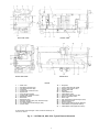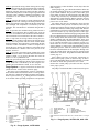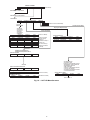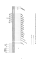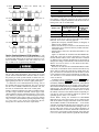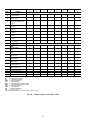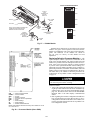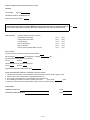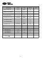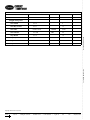
1
16JT
Double-Effect Hermetic Absorption
Liquid Chillers With PIC Controls
Units 810-880, 080-150, 080L-150L
Start-Up, Operation, and
Maintenance Instructions
SAFETY CONSIDERATIONS
Absorption liquid chillers provide safe and reliable service when
operated within design specifications. When operating this equipment, use good judgment and safety precautions to avoid damage
to equipment and property or injury to personnel.
Be sure you understand and follow the procedures and safety precautions contained in the chiller instructions as well as those listed
in this guide.
DO NOT USE OXYGEN or air to purge lines, leak test, or pressurize
a chiller. Use dry nitrogen.
NEVER EXCEED specified test pressures. For the 16JT chiller, the
maximum pressure is 12 psig (83 kPa).
WEAR goggles and suitable protective clothing when handling lithium bromide, octyl alcohol, inhibitor, lithium hydroxide, and hydrobromic acid. IMMEDIATELY wash any spills from the skin with
soap and water. IMMEDIATELY FLUSH EYES with water and consult a physician.
DO NOT USE eyebolts or eyebolt holes to rig chiller sections or the
entire assembly.
DO NOT work on high-voltage equipment unless you are a qualified
electrician.
DO NOT WORK ON electrical components, including control panels or switches, until you are sure ALL POWER IS OFF and no residual voltage can leak from capacitors or solid-state components.
LOCK OPEN AND TAG electrical circuits during servicing. IF
WORK IS INTERRUPTED, confirm that all circuits are deenergized
before resuming work.
NEVER DISCONNECT safety devices or bypass electric interlocks
and operate the chiller. Also, never operate the chiller when any safety
devices are not adjusted and functioning normally.
DO NOT syphon lithium bromide or any other chemical by mouth.
BE SURE all hydrogen has been exhausted before cutting into purge
chambers. Hydrogen mixed with air can explode when ignited.
WHEN FLAMECUTTING OR WELDING on an absorption chiller,
some noxious fumes may be produced. Ventilate the area thoroughly
to avoid breathing concentrated fumes.
DO NOT perform any welding or flamecutting to a chiller while it is
under a vacuum or pressurized condition.
NEVER APPLY an open flame or live steam to a refrigerant cylinder. Dangerous overpressure can result. When necessary to heat a
cylinder, use only warm (110 F [43 C]) water.
DO NOT REUSE disposable (nonreturnable) cylinders or attempt to
refill them. It is DANGEROUS AND ILLEGAL. When cylinder is
emptied, evacuate remaining gas pressure, loosen the collar and
unscrew and discard the valve stem. DO NOT INCINERATE.
DO NOT ATTEMPT TO REMOVE fittings, covers, etc., while
chiller is under pressure, vacuum or while chiller is running.
→ CONNECT THE ABSORPTION CHILLER to an emergency power
source to ensure that a constant power supply is maintained to the unit
in the event that the main electrical power source is interrupted or
temporarily lost. Failure to provide an emergency power source to the
chiller could result in crystallization of the lithium bromide solution
inside the machine, rendering it temporarily inoperative. A potentially
lengthy decrystallization process might be required to return the
chiller to normal operation depending on the severity of the crystallization and/or the length of time the machine was without power.
→ PROVIDE AN EMERGENCY POWER SOURCE to the chilled
water and condenser water pumps to prevent the possibility of an
evaporator freeze-up. Failure to provide emergency power to these
pumps could result in machine operation with no flow of water
through the tubeside of the evaporator, absorber and condenser sections thereby allowing the water inside the evaporator tubes to freeze.
Further, a frozen evaporator tube can burst causing contamination of
the lithium bromide solution and the inside of the chiller. A freeze-up
in the evaporator will also result in a long period of chiller down time
due to the extensive repairs required to bring the chiller and the lithium bromide solution back to its original condition.
DO NOT climb over a chiller. Use platform, catwalk or staging. Follow safe practices when using ladders.
DO NOT STEP ON chiller piping. It might break or bend and cause
personal injury.
USE MECHANICAL EQUIPMENT (crane, hoist, etc.) to lift or
move inspection covers or other heavy components. Even if components are light, use such equipment when there is a risk of slipping
or losing your balance.
VALVE OFF AND TAG steam, water or brine lines before opening
them.
DO NOT LOOSEN waterbox cover bolts until the waterbox has been
completely drained.
DO NOT VENT OR DRAIN waterboxes containing industrial brines,
liquid, gases, or semisolids without permission of your process control group.
BE AWARE that certain automatic start arrangements can engage
starters. Open the disconnects ahead of the starters in addition to shutting off the chiller or pump.
USE only repaired or replacement parts that meet the code requirements of the original equipment.
DO NOT ALLOW UNAUTHORIZED PERSONS to tamper with
chiller safeties or to make major repairs.
PERIODICALLY INSPECT all valves, fittings, piping, and relief
devices for corrosion, rust, leaks, or damage.
PROVIDE A DRAIN connection in the vent line near each pressure
relief device to prevent a build-up of condensate or rain water.
IMMEDIATELY wipe or flush the floor if lithium bromide or octyl
alcohol is spilled on it.
Manufacturer reserves the right to discontinue, or change at any time, specifications or designs without notice and without incurring obligations.
PC 211
Catalog No. 531-610
Printed in U.S.A.
Form 16JT-3SS
Pg 1
901
2-97
Replaces: New
Book 2
Tab 5b
CONTENTS
Page
SAFETY CONSIDERATIONS . . . . . . . . . . . . . . . . . . . 1
Page
• MANUAL CAPACITY VALVE CONTROL
• PIC CONCENTRATION CONTROL
(Solution High Concentration)
Remote Start/Stop Controls . . . . . . . . . . . . . . . . . . 35
Tower Fan Relay . . . . . . . . . . . . . . . . . . . . . . . . . . . . 35
Control Wiring . . . . . . . . . . . . . . . . . . . . . . . . . . . . . . 35
Water/Brine Reset . . . . . . . . . . . . . . . . . . . . . . . . . . . 51
• RESET TYPE 1
• RESET TYPE 2
• RESET TYPE 3
Spare Safety Inputs . . . . . . . . . . . . . . . . . . . . . . . . . 51
• SPARE ALARM CONTACT
Safety Controls . . . . . . . . . . . . . . . . . . . . . . . . . . . . . 51
Service Operation . . . . . . . . . . . . . . . . . . . . . . . . . . . 51
• TO ACCESS THE SERVICE SCREENS
• TO CHANGE THE PASSWORD
• TO CHANGE THE LID DISPLAY FROM ENGLISH
TO METRIC UNITS
• TO SCHEDULE HOLIDAYS
Carrier Comfort Network (CCN) Interface . . . . . 54
Attach to Network Device Control . . . . . . . . . . . . 54
• ATTACHING OTHER CCN MODULES
• LOG OUT TO NETWORK DEVICE
Power-Up . . . . . . . . . . . . . . . . . . . . . . . . . . . . . . . . . . . 55
BEFORE INITIAL START-UP . . . . . . . . . . . . . . . . 55-59
Job Data and Tools Required . . . . . . . . . . . . . . . . 55
Inspect Field Piping . . . . . . . . . . . . . . . . . . . . . . . . . 55
Inspect Field Wiring . . . . . . . . . . . . . . . . . . . . . . . . . 55
Standing Vacuum Test . . . . . . . . . . . . . . . . . . . . . . 56
• LONG INTERVAL TEST
• SHORT INTERVAL TEST
Chiller Evacuation . . . . . . . . . . . . . . . . . . . . . . . . . . 57
Set Up Chiller Control Configuration . . . . . . . . . 57
Input the Design Set Point . . . . . . . . . . . . . . . . . . . 57
Input the Local Occupied Schedule
(OCCPC01S) . . . . . . . . . . . . . . . . . . . . . . . . . . . . . . 57
Input the Service Configuration . . . . . . . . . . . . . . 57
• PASSWORD
• INPUT TIME AND DATE
• CHANGE THE LID CONFIGURATION, IF
NECESSARY
• MODIFY CONTROLLER IDENTIFICATION, IF
NECESSARY
• INPUT EQUIPMENT SERVICE PARAMETERS, AS
NECESSARY
• MODIFY EQUIPMENT CONFIGURATION, AS
NECESSARY
Charge the Chiller With Solution and
Refrigerant . . . . . . . . . . . . . . . . . . . . . . . . . . . . . . . 58
• HANDLING LITHIUM BROMIDE (LiBr) SOLUTION
• CHARGING SOLUTION
• CHARGING SOLUTION FOR CONDITIONS OTHER
THAN NOMINAL
• INITIAL REFRIGERANT CHARGING
INITIAL CONTROL CHECKOUT AND
ADJUSTMENT . . . . . . . . . . . . . . . . . . . . . . . . . . . 59,60
Perform an Automated Control Test . . . . . . . . . . 59
To Prevent Accidental Start-Up . . . . . . . . . . . . . . 59
INITIAL START-UP . . . . . . . . . . . . . . . . . . . . . . . . . 61-68
Preliminary Check . . . . . . . . . . . . . . . . . . . . . . . . . . 61
• PREPARATION
Final Adjustment of Capacity Controls . . . . . . . 61
Final Refrigerant Charge Adjustment . . . . . . . . . 62
Check Chiller Operating Conditions . . . . . . . . . . 62
Check Chiller Shutdown . . . . . . . . . . . . . . . . . . . . . 62
Check Low Refrigerant Level Operation . . . . . . 68
Determine Noncondensable
Accumulation Rate . . . . . . . . . . . . . . . . . . . . . . . . 68
INTRODUCTION . . . . . . . . . . . . . . . . . . . . . . . . . . . . . . 4
ABBREVIATIONS AND EXPLANATIONS . . . . . . . 4
CHILLER DESCRIPTION . . . . . . . . . . . . . . . . . . . . 4-12
Chiller Information and Nameplate . . . . . . . . . . . . 4
Basic Absorption Cycle . . . . . . . . . . . . . . . . . . . . . . 4
Double-Effect Reconcentration . . . . . . . . . . . . . . . . 4
Chiller Components . . . . . . . . . . . . . . . . . . . . . . . . . . 4
Flow Circuits . . . . . . . . . . . . . . . . . . . . . . . . . . . . . . . . 5
Equilibrium Diagram and Chiller
Solution Cycle . . . . . . . . . . . . . . . . . . . . . . . . . . . . . 5
• PLOTTING THE SOLUTION CYCLE
Purge System . . . . . . . . . . . . . . . . . . . . . . . . . . . . . . . 12
CONTROLS . . . . . . . . . . . . . . . . . . . . . . . . . . . . . . . 13-55
Definitions . . . . . . . . . . . . . . . . . . . . . . . . . . . . . . . . . . 13
• ANALOG SIGNAL
• DIGITAL SIGNAL
Overview . . . . . . . . . . . . . . . . . . . . . . . . . . . . . . . . . . . 13
PIC System Components . . . . . . . . . . . . . . . . . . . . 13
• MASTER COMFORT CONTROLLER (PC6400)
MODULE
• PROCESSOR/SENSOR INPUT/OUTPUT MODULE
(Slave PSIO)
• FIRST 8-INPUT MODULE
• SECOND 8-INPUT MODULE
• THIRD 8-INPUT MODULE
• LOCAL INTERFACE DEVICE (LID)
• SIX-PACK RELAY BOARDS
• TEMPERATURE SENSORS
• PRESSURE TRANSDUCERS
• LEVEL PROBES
LID Operation and Menus . . . . . . . . . . . . . . . . . . . 15
• OVERVIEW
• ALARMS AND ALERTS
• LID MENU ITEMS
• BASIC LID OPERATIONS (Using the Softkeys)
• TO VIEW POINT STATUS
• OVERRIDE OPERATIONS
• TIME SCHEDULE OPERATION
• TO VIEW AND CHANGE SET POINTS
• TO ACCESS THE SERVICE MENU TABLES
• LID DISPLAY SCREENS
PIC System Functions . . . . . . . . . . . . . . . . . . . . . . . 22
• CAPACITY CONTROL
• ENTERING CHILLED WATER CONTROL
• CONTROL POINT DEADBAND
• PROPORTIONAL BANDS AND GAIN
• CHILLER TIMERS
• OCCUPANCY SCHEDULE
PIC Control Tests . . . . . . . . . . . . . . . . . . . . . . . . . . . 31
• AUTOMATED TEST
• PC6400 INPUTS TEST
• PC6400 OUTPUTS TEST
• SLAVE PSIO INPUTS TEST
• SLAVE PSIO OUTPUTS TEST
• FIRST 8-INPUT MODULE INPUTS TEST
• SECOND 8-INPUT MODULE INPUTS TEST
• THIRD 8-INPUT MODULE INPUTS TEST
• CAPACITY VALVE ACTUATOR TEST
Ramp Loading Control . . . . . . . . . . . . . . . . . . . . . . 33
Solution Concentration Control . . . . . . . . . . . . . . 34
• FIRST STAGE
• SECOND STAGE
• THIRD STAGE
• CAPACITY OVERRIDES
2
CONTENTS (cont)
Page
Page
Instruct the Operator . . . . . . . . . . . . . . . . . . . . . . . . 68
• PURGE OPERATION
• CONTROL SYSTEM
• AUXILIARY EQUIPMENT
• CHILLER CYCLES
• MAINTENANCE
• SAFETY DEVICES AND PROCEDURES
• OPERATIONS KNOWLEDGE
• START-UP, OPERATION, AND MAINTENANCE
MANUALS
START-UP/SHUTDOWN/RECYCLE
SEQUENCE . . . . . . . . . . . . . . . . . . . . . . . . . . . . . 68-76
Local Start-Up . . . . . . . . . . . . . . . . . . . . . . . . . . . . . . 68
Pre-Start . . . . . . . . . . . . . . . . . . . . . . . . . . . . . . . . . . . . 69
Warm-Up . . . . . . . . . . . . . . . . . . . . . . . . . . . . . . . . . . . 71
• CONCENTRATION PROTECTION DURING STARTUP/PULLDOWN FAILURES (Check Method 1)
• WARM-UP FAILURES
Ramp Loading Mode . . . . . . . . . . . . . . . . . . . . . . . . 71
Normal Run Mode . . . . . . . . . . . . . . . . . . . . . . . . . . 71
• CYCLE-GUARD™ CONCENTRATION CONTROL
• CONTROL OVERRIDE AND FAULT PROTECTION
(Check Method 2)
• REFRIGERATION PUMP CAVITATION
PROTECTION (Low Concentration Limit)
• G1 HIGH SOLUTION LEVEL CONTROL
Desolidification Mode (DESOLID) . . . . . . . . . . . . 73
Shutdown Sequence . . . . . . . . . . . . . . . . . . . . . . . . 73
Chilled Water Recycle Mode . . . . . . . . . . . . . . . . . 73
Safety Shutdown . . . . . . . . . . . . . . . . . . . . . . . . . . . . 76
Power Loss Dilution Cycle . . . . . . . . . . . . . . . . . . . 76
OPERATING INSTRUCTIONS . . . . . . . . . . . . . . . 76-78
Operator Duties . . . . . . . . . . . . . . . . . . . . . . . . . . . . . 76
Before Starting the Chiller . . . . . . . . . . . . . . . . . . . 76
Start the Chiller . . . . . . . . . . . . . . . . . . . . . . . . . . . . . 76
Stop the Chiller . . . . . . . . . . . . . . . . . . . . . . . . . . . . . 76
Start-Up After Limited Shutdown . . . . . . . . . . . . . 76
Start-Up After Extended Shutdown . . . . . . . . . . . 77
Start-Up After Below Freezing
Conditions . . . . . . . . . . . . . . . . . . . . . . . . . . . . . . . . 77
Chiller Shutdown — Normal Conditions . . . . . . 77
Chiller Shutdown — Below Freezing
Conditions . . . . . . . . . . . . . . . . . . . . . . . . . . . . . . . . 77
Actions After Abnormal Shutdown . . . . . . . . . . . 77
Actions After Power Interruption . . . . . . . . . . . . . 78
PERIODIC SCHEDULED MAINTENANCE . . . . . . 78
Every Day . . . . . . . . . . . . . . . . . . . . . . . . . . . . . . . . . . 78
Every Month . . . . . . . . . . . . . . . . . . . . . . . . . . . . . . . 78
Every 2 Months . . . . . . . . . . . . . . . . . . . . . . . . . . . . 78
Every 6 Months . . . . . . . . . . . . . . . . . . . . . . . . . . . . 78
Every Year . . . . . . . . . . . . . . . . . . . . . . . . . . . . . . . . . . 78
Every 3 Years . . . . . . . . . . . . . . . . . . . . . . . . . . . . . . . 78
Every 5 Years or 50,000 Hours
(Whichever Comes First) . . . . . . . . . . . . . . . . . . 78
MAINTENANCE PROCEDURES . . . . . . . . . . . . . 78-92
Service Ontime . . . . . . . . . . . . . . . . . . . . . . . . . . . . . 78
Inspect the Control Center . . . . . . . . . . . . . . . . . . . 78
Check Safety and Operating Controls
Monthly . . . . . . . . . . . . . . . . . . . . . . . . . . . . . . . . . . 78
Log Sheets . . . . . . . . . . . . . . . . . . . . . . . . . . . . . . . . . 78
Inspect Rupture Disc and Piping . . . . . . . . . . . . . 78
Inspect the Heat Exchanger Tubes . . . . . . . . . . . 79
• EVAPORATOR
• ABSORBER/CONDENSER
Water Leaks . . . . . . . . . . . . . . . . . . . . . . . . . . . . . . . . 79
Water Treatment . . . . . . . . . . . . . . . . . . . . . . . . . . . . 79
Purge Manual Exhaust Procedure . . . . . . . . . . . . 79
Absorber Loss Determination . . . . . . . . . . . . . . . . 80
Noncondensable Accumulation Rate . . . . . . . . . 80
Chiller Leak Test . . . . . . . . . . . . . . . . . . . . . . . . . . . . 80
• DRY NITROGEN
• REFRIGERANT TRACER
Repair the Chiller Leak, Retest, and Apply a
Standing Vacuum Test . . . . . . . . . . . . . . . . . . . . 81
Chiller Evacuation . . . . . . . . . . . . . . . . . . . . . . . . . . 81
Solution or Refrigerant Sampling . . . . . . . . . . . . 81
• SOLUTION SAMPLE
• REFRIGERANT SAMPLE
Inhibitor . . . . . . . . . . . . . . . . . . . . . . . . . . . . . . . . . . . . 82
Solution Analysis . . . . . . . . . . . . . . . . . . . . . . . . . . . 82
Adding Octyl Alcohol . . . . . . . . . . . . . . . . . . . . . . . . 82
Removing Lithium Bromide from
Refrigerant . . . . . . . . . . . . . . . . . . . . . . . . . . . . . . . 82
Refrigerant Charge Adjustment . . . . . . . . . . . . . . 83
Low Temperature Cutout Adjustment . . . . . . . . . 83
Cycle-Guard™ System Operation . . . . . . . . . . . . 83
Internal Service . . . . . . . . . . . . . . . . . . . . . . . . . . . . . 83
Service Valve Diaphragm Replacement . . . . . . . 83
Hermetic Pump Inspection . . . . . . . . . . . . . . . . . . . 87
• DISASSEMBLY
• INSPECTION
• REASSEMBLY
• COMPLETION
Solution Decrystallization . . . . . . . . . . . . . . . . . . . 87
• DECRYSTALLIZATION USING THE PIC
CONTROLS
• SEVERE CRYSTALLIZATION
Condensing Water Tube Scale . . . . . . . . . . . . . . . 92
Water Treatment . . . . . . . . . . . . . . . . . . . . . . . . . . . . 92
Ordering Replacement Chiller Parts . . . . . . . . . . 92
TROUBLESHOOTING GUIDE . . . . . . . . . . . . . . 92-110
Overview . . . . . . . . . . . . . . . . . . . . . . . . . . . . . . . . . . . 92
Checking the LID Display Messages . . . . . . . . . 92
Checking Temperature Sensors . . . . . . . . . . . . . . 92
• RESISTANCE CHECK
• VOLTAGE DROP
• CHECK TEMPERATURE ACCURACY
Pressure Transducers . . . . . . . . . . . . . . . . . . . . . . 101
• CHECK PRESSURE TRANSDUCERS
• REPLACING TRANSDUCERS
Control Algorithm Checkout Procedure . . . . . . 101
Control Test . . . . . . . . . . . . . . . . . . . . . . . . . . . . . . . 101
Control Modules . . . . . . . . . . . . . . . . . . . . . . . . . . . 101
• RED LED
• GREEN LEDs
Notes on Module Operation . . . . . . . . . . . . . . . . . 106
PC6400 Module . . . . . . . . . . . . . . . . . . . . . . . . . . . . 106
• INPUTS
• OUTPUTS
Processor Module (Slave PSIO) . . . . . . . . . . . . . 106
• INPUTS
• OUTPUTS
First, Second, and Third 8-Input Modules . . . . 106
Replacing Defective Processor Modules . . . . . 107
• INSTALLATION
Physical Data . . . . . . . . . . . . . . . . . . . . . . . . . . . . . . 108
INDEX . . . . . . . . . . . . . . . . . . . . . . . . . . . . . . . . . . 111-114
START-UP CHECKLIST . . . . . . . . . . . . . CL-1 to CL-12
3
To make the cooling process continuous, the refrigerant
vapor must be removed as it is produced. For this, a solution
of lithium bromide (LiBr) salt in water is used to absorb the
water vapor. Lithium bromide has a high affinity for water,
and will absorb it in large quantities under the right conditions. The removal of the refrigerant vapor by absorption keeps
the chiller pressure low enough for the cooling vaporization
to continue. However, this process dilutes the solution and
reduces its absorption capacity. Therefore the diluted lithium
bromide solution is pumped to separate vessels where it is
heated to release (boil off) the previously absorbed water.
Relatively cool condensing water from a cooling tower or
other source removes enough heat from this vapor to condense it again into liquid for reuse in the cooling cycle. The
reconcentrated lithium bromide solution is returned to the
original vessel to continue the absorption process.
INTRODUCTION
Everyone involved in the start-up, operation, and maintenance of the 16JT chiller should be thoroughly familiar
with the following instructions and other necessary job data
before initial start-up and before operating the chiller and its
control system or performing chiller maintenance. Procedures are arranged in the sequence required for proper chiller
start-up and operation.
ABBREVIATIONS AND EXPLANATIONS
CCN
ECW
G1
G2
HX
HX1
HX2
LCD
LCW
LID
PIC
PSIO
RLA
SI
—
—
—
—
—
—
—
—
—
—
—
—
—
—
Carrier Comfort Network
Entering Chilled Water
High-Stage Generator
Low-Stage Generator
Heat Exchanger
High-Temperature Heat Exchanger
Low-Temperature Heat Exchanger
Level Control Device
Leaving Chilled Water
Local Interface Device
Product Integrated Control
Processor/Sensor Input/Output Module
Rated Load Amps
International System of Units (metric)
Double-Effect Reconcentration — The 16JT reconcentrates solution in 2 stages to improve the operating
efficiency. Approximately half of the diluted solution is pumped
to a high-temperature vessel (high stage) where it is heated
directly by high-pressure steam for reconcentration. The other
half of the solution flows to a low-temperature vessel (low
stage) where it is heated for reconcentration by hot water
vapor released in the high-temperature vessel. The low stage
acts as the condenser for the high stage, so the heat energy
first applied in the high-stage vessel is used again in the lowstage vessel. This cuts the heat input to almost half of
that required for an absorption chiller with a single
reconcentrator.
Words printed in all capital letters can be viewed on the
LID (e.g., LOCAL, CCN, RUNNING, ALARM, etc).
Words printed both in all capital letters and italics can also
be viewed on the LID and are parameters (CONTROL MODE,
COOLING SETPOINT, TARGET CAPACITY VALVE, etc.)
with associated values (e.g., modes, temperatures, percentages, pressures, on, off, etc.).
Words printed in all capital letters and in a box represent
softkeys on the LID control panel (e.g.; ENTER , EXIT ).
Factory installed additional components are referred to as
options in this manual; factory supplied but field installed
additional components are referred to as accessories.
Chiller Components — The major sections of
the chiller are contained in several vessels (Fig. 2 and 3,
and Table 1).
The large lower shell contains the evaporator and absorber sections. The evaporator and absorber are positioned
side by side in units 16JT810-880, but the evaporator is
positioned above the absorber in units 16JT080-150,
080L-150L. In the evaporator section, the refrigerant water
vaporizes and cools the chilled water for the air conditioning
or cooling process. In the absorber, vaporized water from
the evaporator is absorbed by lithium bromide solution.
CHILLER DESCRIPTION
Chiller Information and Nameplate — The chiller
nameplate includes model and serial number information
(Fig. 1). See Fig. 2 and 3 for the location of the nameplate
on the chiller.
Basic Absorption Cycle — The 16JT absorption chiller
uses water as the refrigerant in vessels maintained under a
deep vacuum. The chiller operates on the simple principle
that under low absolute pressure (vacuum), water takes up
heat and vaporizes (boils) at a low temperature. For example, at the very deep vacuum of 0.3 in. (6.4 mm) of mercury absolute pressure, water boils at the relatively cool
temperature of only 40 F (4 C). To obtain the energy required for this boiling, it takes heat from, and therefore chills,
another fluid (usually water). The chilled fluid then can be
used for cooling purposes.
Fig. 1 — Model Number Nomenclature
4
The strong (reconcentrated) solution flows from the two
generators back to the absorber spray headers to begin a new
solution cycle. On the way, it passes through solution heat
exchangers where heat is transferred from the hot, strong solution to the cooler, weak solution being pumped to the generators. Solution to and from the high-stage generator
passes through both a high-temperature heat exchanger and
low-temperature heat exchanger. Solution to and from the
low-stage generator passes through only the low-temperature
heat exchanger. This heat transfer improves solution cycle
efficiency by preheating the relatively cool, weak solution
before it enters the generators and precooling the hotter, strong
solution before it enters the absorber. The efficiency is further improved by transferring heat from the hot steam condensate to the cooler, weak solution in the condensate drain
heat exchanger and trap.
The weak solution flowing to the generators passes through
a flow control valve which is positioned by a float in the
high-stage generator overflow box. The purpose of the valve
is to automatically maintain optimum solution flow to the
two generators at all operating conditions for maximum
efficiency.
During high load operation, some abnormal conditions can
cause the lithium bromide concentration to increase above
normal, with the strong solution concentration close to crystallization (see Equilibrium Diagram and Chiller Solution Cycle,
Fig. 6). If, for some reason, the chiller controls do not prevent strong solution crystallization during abnormal operating conditions and flow blockage does occur, the strongsolution overflow pipe will reverse or limit the crystallization
until the cause can be corrected. The overflow pipe is located between the low-stage generator discharge box and the
absorber, bypassing the low-temperature heat exchanger, as
shown in Fig. 4 and 5.
If crystallization occurs, it generally takes place in the shell
side of the low-temperature heat exchanger, blocking the flow
of strong solution from the generators. The strong solution
then backs up in the discharge box and spills over into the
overflow pipe, which returns it directly to the absorber sump.
The solution pump then returns the hot solution through the
heat exchanger tubes, automatically heating and decrystallizing the shell side.
The smaller vessel above the evaporator/absorber assembly is the high-stage generator. Here, approximately half of
the diluted solution from the absorber is heated and reconcentrated to recover slightly over half of the water previously absorbed.
The other shell above the evaporator/absorber assembly
contains the low-stage generator and condenser. The other
half of the diluted solution is heated and reconcentrated in
the low-stage generator by high temperature water vapor from
the high-stage generator. The water vapor released from the
solution in this process is condensed to liquid in the condenser section.
The 16JT chiller also has two solution heat exchangers
and a steam condensate heat exchanger to improve operating economy; an external purge system to maintain chiller
vacuum by the removal of noncondensables; hermetic pumps
to circulate the solution and refrigerant; and various operational, capacity, and safety devices to provide automatic, reliable chiller performance.
Table 1 — 16JT Description
ABSORBER/
POINTS
SOLUTION PURGE
EVAPORATOR
AND
PUMPS
CONFIGURATION
EDUCTORS
810-854
Side-by-side
1
1
857,865
Side-by-side
1
2
873,880
Side-by-side
2
2
080-120
Over-and-under
2
4
135, 150
Over-and-under
3
4
080L-120L
Over-and-under
2
4
135L,150L
Over-and-under
3
4
UNIT
16JT
Flow Circuits — Figures 4 and 5 illustrate the basic flow
circuits of the 16JT absorption chiller.
The liquid to be chilled is passed through the evaporator
tube bundle and is cooled by the evaporation of refrigerant
water sprayed over the outer surface of the tubes by the recirculating refrigerant pump. The refrigerant vapors are drawn
into the absorber section and are absorbed by the lithium
bromide-water solution sprayed over the absorber tubes. The
heat picked up from the chilled liquid is transferred from the
absorbed vapor to the cooling water flowing through the absorber tubes.
The solution in the absorber becomes diluted as it absorbs
water and loses its ability to continue the absorption process. It is then transferred by the solution pump to the generator sections to be reconcentrated. Approximately half of
the weak (diluted) solution goes to the shell side of the highstage generator where it is heated by high-pressure steam.
This boils out its absorbed water. This high-temperature refrigerant water vapor passes to the low-stage generator tubes.
In the shell side of the low-stage generator, the rest of the
weak solution is heated by the high-temperature refrigerant
water vapor from the high-stage generator. This boils out its
absorbed water.
The refrigerant water vapor boiled from the low-stage generator solution passes into the condenser section and condenses on tubes containing cooling water. This is the same
cooling water which had just flowed through the absorber
tubes. On the tube side of the low-stage generator, the condensed high-temperature refrigerant water passes into the condenser, where it is cooled to the condenser temperature. The
combined condensed refrigerant water from the two generators now flows back to the evaporator to begin a new refrigerant cycle.
Equilibrium Diagram and Chiller Solution
Cycle — A sample solution cycle can be illustrated by plotting it on a basic equilibrium diagram for lithium bromide in
solution with water (Fig. 6). The diagram is also used for
performance analyses and troubleshooting. Figure 7 may be
used to plot the solution cycle for your 16JT chiller.
The left scale on the diagram indicates solution and water
vapor pressures at equilibrium conditions. The right scale
indicates the corresponding saturation (boiling or condensing) temperatures for both the refrigerant (water) and the
solution.
The bottom scale represents solution concentration, expressed as percentage of lithium bromide by weight in solution with water. For example, a lithium bromide concentration of 60% means 60% lithium bromide and 40% water
by weight.
The curved lines running diagonally left to right are solution temperature lines (not to be confused with the horizontal saturation temperature lines). The single curved line
at the lower right represents the crystallization line. The solution becomes saturated at any combination of temperature
and concentration to the right of this line, and it will begin
to crystallize (solidify) and restrict flow.
5
LEFT END VIEW
FRONT VIEW
RIGHT END VIEW
REAR VIEW
LEGEND
1
2
3
4
5
6
7
8
9
10
11
12
13
—
—
—
—
—
—
—
—
—
—
—
—
—
Steam Inlet
High-Stage Generator (G1)
Low-Stage Generator (G2)
Cooling Water Outlet
Condenser
Rupture Disc
Purge Storage Chamber
Control Center
Generator Overflow (GO) Loop Heat Exchanger
Knockout Chamber
Low-Temperature Heat Exchanger (HX2)
Name Plate
Absorber
14
15
16
17
18
19
20
21
22
23
24
25
—
—
—
—
—
—
—
—
—
—
—
—
Cooling Water Inlet
Evaporator
Chilled Water Outlet
LCD (Level Control Device) Box
Steam Condensate Outlet
Steam Trap
Refrigerant Pump
Drain Heat Exchangers (Second One is Optional)
High Temperature Heat Exchanger (HX1)
Solution Pump
Chilled Water Inlet
Solution Pump Service Valve
Fig. 2 — 16JT810-880 Typical External Schematic
6
LEFT END VIEW
FRONT VIEW
RIGHT END VIEW
REAR VIEW
LEGEND
1
2
3
4
5
6
7
8
9
10
11
12
13
14
15
—
—
—
—
—
—
—
—
—
—
—
—
—
—
—
Steam Inlet
High-Stage Generator (G1)
Low-Stage Generator (G2)
Condenser
Cooling Water Condenser Inlet
Rupture Disc
Purge Storage Chamber
Cooling Water Condenser Outlet
Refrigerant Chamber
Name Plate
Refrigerant Pump
Generator Overflow (GO) Loop Heat Exchanger
Knockout Chamber
Low-Temperature Heat Exchanger (HX2)
Control Center
16
17
18
19
20
21
22
23
24
25
26
27
28
29
30
31
—
—
—
—
—
—
—
—
—
—
—
—
—
—
—
—
Evaporator
Cooling Water Absorber Outlet
Solution Pump Service Valve
Cooling Water Inlet
Absorber
Chilled Water Inlet
Chilled Water Outlet
LCD (Level Control Device) Box
Steam Condensate Outlet
Steam Trap*
High Temperature Heat Exchanger (HX1)
Drain Heat Exchanger
Solution Pump(s)
Second Drain Heat Exchanger (Optional)
Chilled Water Inlet (Optional Location)
Chilled Water Outlet (Optional Location)
*If optional drain heat exchanger is used, locate the steam trap on
Item 29 vs. Item 27.
Fig. 3 — 16JT080-150, 080L-150L: Typical External Schematic
7
LEGEND
EA1
EA2
EA4
FA1
FA2
LCD
LC
PA1
—
—
—
—
—
—
—
—
PI1
—
PIC
TA1
TA3
—
—
—
TA4
— Solution Pump Motor HighTemperature Cutout
TA5
— Solution High-Temperature Cutout
TI 1-4
— Weak Solution Thermocouples
TI 5-8
— Strong Solution Thermocouples
TI 9-10 — Refrigerant Thermocouples
TI 11-12 — Cooling Water Thermocouples
TI 13-14 — Chilled Water Thermocouples
Control Wiring
Refrigerant Pump Overload Cutout
Solution Pump Overload Cutout
Vacuum Pump Motor Overload
Chilled Water Low-Flow Cutout
Cooling Water Low-Flow Cutout
Level Control Device
Refrigerant Level Switches
High-Pressure Switch (High-Stage
Generator)
Compound Gage (High-Temperature
Generator)
Product Integrated Control
Chilled-Water Low-Temperature Cutout
Refrigerant Pump Motor HighTemperature Cutout
Piping Connections
Valve
NOTES:
1. Spray pump and second solution pump are located on large sizes only.
2. Vacuum pump is optional.
3. Electric capacity control is shown. (Pneumatic is optional.)
*The LCD valve is physically located with the float in the high stage generator overflow box, not
where it is schematically shown in the illustration.
Fig. 4 — Typical Flow Circuits, with Data Points, Shown for 16JT080-150,080L-150L Arrangements
LCD — Level Control Device
TC
— Temperature Control (Capacity Control)
Fig. 5 — Typical Flow Circuits, (Simplified) Arrangement Shown for 16JT810-880
8
9
0
5
1.05
10
1.10
15
1.15
20
1.20
25
1.25
30
1.30
35
1.35
40
AVITY
.4
)
SPECIFIC GR
(4
1.50
0)
0.
1.52
(1
1.56
1.54
60
VAPOR PRESSURE IN INCHES OF MERCURY ABSOLUTE
Fig. 6 — Equilibrium Diagram and Chiller Solution Cycle Example
55
5)
5.
1.58
(1
1.60
70
1)
1.
(2
10
.7)
13
(26
60
80
1.68
50
50
1.64
2'
2
3
4
5
)
F (C
6
1.66
1.40
% LITHIUM BROMIDE BY WEIGHT IN SOLUTION
45
1.45
40
RE
RA
TU
PE
TEM
11
14
1
12
32
.2)
90
(
1.70
0.1 (2.5)
ION
LUT
7
1.74
0.2 (5.1)
0.5 (12.7)
1.0 (25.4)
2.0 (50.6)
5.0 (126.6)
10.0 (254)
15.0 (381)
20.0 (508)
1.62
9
8
(37.
8)
)
110
(43.
3
100
65
9X
(65
.5)
140
(60.
0)
130
(54
.4)
120
(78.
9)
14X
150
190
(87
.8)
180
(82
.2)
170
(76.
6)
160
(71.
1)
(154
.4
300
(148 )
.9)
290
(143
.3)
280
(137
.8)
270
(132
.2)
260
(12
6.7)
250
(12
1,1
)
240
(115
.6)
230
(110
.0)
220
(104
.4)
210
(98.
9)
200
(93.
3)
310
E
1.72
LIN
1.76
ION
SO
1.78
CR
YST
A
1.80
LLIZ
AT
25.0 (635)
70
20 (-6.7)
30 (-1.1)
40 (4.4)
50 (10.0)
60 (15.5)
70 (21.1)
80 (26.7)
90 (32.2)
100 (37.8)
110 (43.3)
120 (48.9)
130 (54.4)
140 (60.0)
150 (65.5)
160 (71.1)
170 (76.6)
180 (82.2)
190 (87.8)
200 (93.3)
WEAK LiBr SATURATION TEMPERATURE F (C)
0
5
1.05
10
1.10
15
1.15
20
1.20
25
1.25
30
1.30
35
1.35
40
AVITY
.4
)
SPECIFIC GR
(4
1.50
0)
0.
1.52
(1
1.56
1.54
60
1.64
1)
1.
(2
1.60
VAPOR PRESSURE IN INCHES (mm) OF MERCURY ABSOLUTE
Fig. 7 — Equilibrium Diagram for Plotting 16JT Solution Cycle
.7)
(26
60
80
1.68
55
5)
5.
1.58
(1
1.62
70
1.66
50
50
32
.2)
90
(
1.70
1.40
% LITHIUM BROMIDE BY WEIGHT IN SOLUTION
45
40
)
F (C
1.72
0.1 (2.5)
RE
RA
TU
PE
TEM
65
(37.
8)
)
110
(43.
3
100
(65
.5)
140
(60.
0)
130
(54
.4)
120
(78.
9)
150
190
(87
.8)
180
(82
.2)
170
(76.
6)
160
(71.
1)
310
(154
.4
300
(148 )
.9)
290
(143
.3)
280
(137
.8)
270
(132
.2)
260
(12
6.7)
250
(12
1,1
)
240
(115
.6)
230
(110
.0)
220
(104
.4)
210
(98.
9)
200
(93.
3)
1.76
0.2 (5.1)
0.5 (12.7)
1.0 (25.4)
2.0 (50.6)
5.0 (126.6)
10.0 (254)
15.0 (381)
ION
LUT
E
10
LIN
SO
1.45
ION
20.0 (508)
1.78
CR
YST
A
1.80
LLIZ
AT
25.0 (635)
70
20 (-6.7)
30 (-1.1)
40 (4.4)
50 (10.0)
60 (15.5)
70 (21.1)
80 (26.7)
90 (32.2)
100 (37.8)
110 (43.3)
120 (48.9)
130 (54.4)
140 (60.0)
150 (65.5)
160 (71.1)
170 (76.6)
180 (82.2)
190 (87.8)
200 (93.3)
WEAK LiBr SATURATION TEMPERATURE F (C)
1.74
The slightly sloped vertical lines extending from the bottom of the diagram are solution specific gravity lines. The
concentration of a lithium bromide solution sample can be
determined by measuring its specific gravity with a hydrometer and reading its temperature. Plotting the intersection
point for these 2 values and reading straight down to the percent lithium bromide scale will give the concentration. The
corresponding vapor pressure can also be determined by reading the scale straight to the left of the point, and its saturation temperature can be read on the scale straight to the right.
PLOTTING THE SOLUTION CYCLE — An absorption solution cycle at typical full load conditions is plotted in
Fig. 6 from Points 1 through 14X. The corresponding values
for these typical points are listed in Table 2. Note that
these values will vary with different loads and operating
conditions.
Point 1 represents the strong solution in the absorber as it
begins to absorb water vapor after being sprayed from the
absorber nozzles. This condition is internal and cannot be
measured.
Point 2 represents the diluted (weak) solution after it leaves
the absorber and before it enters the low-temperature heat
exchanger. This includes the weak solution’s flow through
the solution pump. Point 2 is also used to calculate absorber
loss.
Point 28 represents the theoretical point calculated by refrigerant temperature and the concentration measured by the refrigerant level. Point 28 is used to calculate absorber loss
and can be measured with a solution sample from the pump
discharge. The Product Integrated Control (PIC) monitors
Point 28 via the refrigerant temperature and calculates solution concentration based on the refrigerant level. For more
information on the PIC, see the Controls section, page 13.
Point 3 represents the weak solution leaving the lowtemperature heat exchanger. The solution is at the same concentration as at Point 2, but at a higher temperature after
gaining heat from the strong solution. This temperature is
measured by the PIC controller.
Point 4 represents the weak solution leaving the drain heat
exchanger. It is at the same concentration as Point 3, but at
a higher temperature after gaining heat from the steam condensate. Its temperature can be measured manually at a well
provided for this purpose. At this point, the weak solution
first flows through the level control device (LCD) valve and
is then split, with approximately half going to the low-stage
generator and the rest going on to the high-temperature heat
exchanger.
Point 5 represents the weak solution in the low-stage generator after being preheated to the boiling temperature. The
solution will boil at temperatures and concentrations corresponding to a saturation temperature established by the refrigerant vapor condensing temperature in the condenser. This
condition is internal and cannot be measured.
Point 6 represents the weak solution leaving the hightemperature heat exchanger and entering the high-stage generator. It is at the same concentration as Point 4 but at a higher
temperature after gaining heat from the strong solution. This
temperature is measured by the PIC controller.
Point 7 represents the weak solution in the high-stage generator after being preheated to the boiling temperature. The
solution will boil at temperatures and concentrations corresponding to the saturation temperature established by the refrigerant vapor condensing temperature in the low-stage
generator tubes. The concentration is the same as Point 6 but
at a higher temperature; this temperature is measured by the
PIC controller which measures the condensed refrigerant vapor leaving the low-stage generator tubes.
Point 8 represents the strong solution leaving the high-stage
generator and entering the high-temperature heat exchanger
after being reconcentrated by boiling out refrigerant water.
It can be plotted by measuring the temperatures of the leaving strong solution and the condensed refrigerant vapor leaving the low-stage generator tubes (saturation temperature).
These two temperatures are measured by the PIC controller
and used to calculate the strong solution concentration.
Point 9 represents the strong solution from the high-temperature
heat exchanger as it flows between the two heat exchangers.
It is the same concentration as Point 8 but at a cooler temperature after giving up heat to the weak solution. The temperature is measured by the PIC controller.
Point 9X represents the point on the crystallization line that
corresponds to the conditions at Point 9 if the solution were
cooled. This point is calculated by the PIC using the temperature and concentration at Point 9 as a reference.
Table 2 — Typical Full Load Cycle Equilibrium Data
POINT
1
2
2*
3
4
5
6
7
8
9
9X
10
11
12
13
14
14X
SOLUTION TEMPERATURE
F
C
120
49
103
39
100
38
149
65
160
71
171
77
279
137
290
143
318
159
175
79
175
79
186
86
182
83
126
52
120
49
118
48
118
48
VAPOR PRESSURE
in. Hg
mm Hg
0.3
6
0.3
6
0.2
5
1.0
25
1.4
35
1.9
48
18.0
156
24.0
608
24.0
608
1.1
28
0.7
18
1.9
48
1.6
41
0.3
8
0.3
7
0.2
6
0.2
4
11
SOLUTION PERCENTAGE
%
62.6
58.0
58.0
58.0
58.0
58.0
58.0
58.0
63.8
63.8
67.5
61.5
62.6
62.6
61.5
62.2
65.0
SATURATED TEMPERATURE
F
C
40
4.4
40
4.4
36
2.2
79
26.0
90
32.0
100
38.0
190
88.0
200
93.0
200
93.0
82
28.0
68
20.0
100
38.0
93
34.0
45
7.2
43
6.1
38
3.3
29
−1.7
and, because they reduce the chiller vacuum, they reduce the
chiller capacity.
Some hydrogen (H2) gas is liberated within the chiller during normal operation and its rate of generation is controlled
by the solution inhibitor. The presence of most other gases
in the chiller would occur either through a leak (the chiller
is under a deep vacuum) or by entrainment in the refrigerant
and solution at initial charging. During operation, noncondensables accumulate in the absorber, which is the lowest
pressure area of the chiller.
For purging, the gases are continuously drawn from the
absorber into the lower pressure of eductors, where they are
entrained in solution flowing from the solution pump. The
mixture then continues on to the purge storage tank. The noncondensables are released in a separator and the solution flows
back to the absorber by way of the generator overflow pipe.
Noncondensables accumulate in the purge storage tank where
they are isolated from the rest of the chiller. The storage chamber is initially filled with solution that is displaced as the
chamber gradually fills with noncondensables. These gases
then must be periodically exhausted from the storage chamber by a manual procedure. This is begun by closing a solution return valve to force solution from the pump into the
storage chamber to compress the noncondensables to above
atmospheric pressure. Then the exhaust valve is opened to
bleed the noncondensables to the atmosphere through solution in the exhaust bottle. This operation is described in the
Maintenance Procedures, Purge Manual Exhaust Procedure
section, page 79.
Some chillers also have an optional, permanently installed vacuum pump system (as shown in Fig. 4) that removes noncondensables directly from the absorber to evacuate
the chiller at initial start-up and after service work.
NOTE: This vacuum pump system does not take the place
of the purge system.
The pump is wired into the chiller control circuit for power.
Point 10 represents the strong solution leaving the low-stage
generator and entering the low-temperature heat exchanger.
It is at a weaker concentration than the solution from the
high-stage generator and can be plotted. The PIC controller
measures the temperatures of the leaving strong solution and
refrigerant vapor condensate (saturation temperature). The
concentration of the solution is calculated by the PIC
controller.
Point 11 represents the mixture of strong solution from the
high-temperature heat exchanger and strong solution from
the low-stage generator as they both enter the low-temperature
heat exchanger. The temperature is measured by the PIC
controller. The concentration is calculated using Points 9
and 10.
Point 12 represents the combined strong solution before it
leaves the low-temperature heat exchanger after giving up
heat to the weak solution. This condition is internal and cannot be measured. The concentration is the same as Point 11.
Point 13 represents the strong solution leaving the lowtemperature heat exchanger and entering the absorber spray
nozzles, after being mixed with some weak solution inside
the heat exchanger. The temperature is measured by the PIC
controller, but the concentration cannot be sampled. After
leaving the spray nozzles, the solution is somewhat cooled
and concentrated as it flashes to the lower pressure of the
absorber, at Point 1.
Point 14 represents a theoretical point calculated by using
the concentration at Point 12 and the solution saturation temperature at Point 2. It is used to determine how close the
chiller is to the crystallization line.
Point 14X represents the point on the crystallization line that
corresponds to the conditions at Point 14 if the solution were
cooled. Point 14X is calculated by the PIC using the temperature and concentration at Point 14 as a reference.
Purge System — Figures 8 and 9 show the basic components and flow circuits of the motorless purge.
The purge system automatically removes noncondensables from the chiller and transfers them to a storage chamber where they cannot affect chiller operation. Noncondensables are gases such as N2, O2, and H2 that will not condense
at the normal chiller operating temperatures and pressures
LEGEND
1
2
3
4
5
6
LEGEND
1
2
3
4
—
—
—
—
Storage Chamber
Auxiliary Valve
Eductor
Solution from Solution
Pump
5 — Solution Returning to
Absorber
6
7
8
9
10
—
—
—
—
—
—
—
—
—
—
—
Storage Chamber
Solution Return Valve
Eductor
Eductor
GO-Loop Box
Eductor
7
8
9
10
11
—
—
—
—
—
Eductor
Solution Pumps
Separation Chamber
Exhaust Bottle (Liquid Seal)
Exhaust Valve
NOTE: Number of eductors varies from one on smaller sizes to 4 on larger
sizes.
Check Valve
Exhaust Bottle (Liquid Seal)
Solution Return Valve
Separation Chamber
Exhaust Valve
Fig. 9 — Purge System, 16JT080-150, 080L-150L
Fig. 8 — Purge System, 16JT810-880
12
Definitions
CONTROLS
PIC System Components — The Product Integrated
Control (PIC) is the chiller’s control system. The PIC controls the operation of the chiller by monitoring all operating
conditions. The PIC can also diagnose a problem with the
chiller. It positions the steam valve to maintain leaving chilled
water temperature. The PIC can also interface with auxiliary
equipment such as pumps and cooling tower fans so that they
turn on only when required. The PIC checks all safeties to
prevent any unsafe operating conditions.
The PIC can interface with the Carrier Comfort Network
(CCN), if desired and can communicate with other PICequipped chillers and other CCN devices.
The PIC system consists of five modules housed inside
the control center (Fig. 10):
• Master Comfort Controller (PC6400)
• Processor/Sensor Input/Output (Slave PSIO) Module
• First 8-Input Module
• Second 8-Input Module
• Third 8-Input Module
The PIC system also includes the following components:
• LID
• Six-Pack Relay Boards
• Temperature Sensors
• Pressure Transducers
ANALOG SIGNAL — An analog signal varies in proportion to the monitored source. It quantifies values between
operating limits. For example, a temperature sensor is an analog device because its resistance changes in proportion to
the temperature and it detects many values.
DIGITAL SIGNAL — A digital (discrete) signal is a twoposition representation of the value of a monitored source.
For example, a switch is a digital device because it only indicates whether a value is above or below a set point or boundary by generating an on/off, high/low, or open/closed signal.
Overview — The 16JT absorption liquid chiller contains
a microprocessor-based control center that monitors and controls all operations of the chiller. The microprocessor control system matches the cooling capacity of the chiller to the
cooling load while providing state-of-the-art chiller protection. The system controls cooling capacity within the set point
plus the deadband by sensing the leaving or entering chilled
water temperature and regulating the steam valve via a
mechanically-linked actuator. Movement of the valve causes
the steam rate to increase or decrease, thereby increasing or
decreasing the chiller’s capacity. The processor protects the
chiller by monitoring the digital and analog inputs and executes capacity overrides or safety shutdowns, if required.
SIDE VIEW
FRONT VIEW
INTERNAL VIEW
1 — Fused Disconnect
2 — Low Voltage Transformers
(TR1, TR2, TR3, TR5)
3 — 6-Pack Relay Boards (2)
4 — PC6400 (Master Comfort
Controller)
5 — Slave PSIO (Processor/Sensor
Input/Output Module)
6 — 8-Input Modules (3)
7 — Location for Spare Modules (3)
8 — Circuit Breakers (4)
9 — Low Voltage Transformer, TR4
10 — Terminal Blocks (3)
11 — Pump Motor Overloads (5)
12
13
14
15
16
17
18
19
20
21
8-IN
CR
FB
GL
—
—
—
—
—
—
—
—
—
—
—
—
—
—
LEGEND
Pump Fuse Blocks (5)
Control Relays (7)
Primary Power Transformer (TR7)
Cooling Fan
Indicator Lights
Vacuum Pump Start Button
Vacuum Pump Stop Button
Cycle-Guard™ Auto/Manual Switch
Panel Vent
Panel Door Handle
8 Input Module
Control Relay
Fuse Block
Ground Lug
LID
— Local Interface Device
MDC
— Main Disconnect
NEMA — National Electrical Manufacturer’s
Association
OL
— Overload
PSIO — Processor/Sensor Input/Output
Module
RB
— Relay Board
RP
— Refrigerant Pump Contactor
SP
— Solution Pump Contactor
SSP
— Solution Spray Pump Contactor
TB
— Terminal Block
TR
— Transformer
VP
— Vacuum Pump Contactor
Fig. 10 — Typical 16JT Chiller PIC Control Center
13
The control center is divided into two areas. The control
voltages contained in each area of the control center are:
• upper right side: all extra-low voltage wiring (24 v or less)
• left side: 115 vac control voltage and chiller high power
wiring
Figure 11 is a schematic representation of the PIC control
system.
LID (Local Interface Device)
LID
!
INPUTS
1. Cycle-Guard™ Auto/Manual Switch
2. Weak LiBr Leaving LCD Box
3. Strong LiBr Leaving G1
4. Weak LiBr Leaving High HX1
5. Strong LiBr Leaving G2
6. G2 LiBr Overflow Pipe
7. Strong LiBr Leaving High HX1
8. Stop Button on LID
1. Transducer Reference Voltage
2. G1 Internal Pressure
3. Solution Pump No.1 Pressure
4. Solution Pump No. 2 Pressure
5. Refrigerant Level Sensor
6. Refrigerant Temperature
7. Entering Chilled Water
8. Leaving Chilled Water
9. Weak LiBr Leaving Absorber
10. Weak LiBr Leaving Low HX2
11. Cooling Water Entering Absorber
12. Cooling Water Leaving Absorber
1. Vapor Condensate Temperature
2. Condensate Temp. from G2
(Refrigerant)
3. Cooling Water Leaving Condenser
4. Strong LiBr Leaving Low HX2
5. Remote Contacts
6. Recirculated LiBr Entering
Absorber
7. G1 High Temp/Pressure Cutout
8. Low Chilled Water Temp
1. Chilled Water Flow
2. Cooling Water Flow
3. G1 High LiBr Level
4. Spare Protective Limit
5. Refrigerant Pump
Overload/High Temp
6. Solution Pump No.1
Overload/High Temp
7. Solution Pump No. 2
Overload/High Temp
8. Solution Spray Pump
Overload/High Temp
1. Temperature Reset
2. Remote Reset Sensor
3. Common Supply Sensor
4. Common Return Sensor
5. Refrigerant Dilution Level
6. Low Refrigerant Level
7. High Refrigerant Level
8. Spare
OUTPUTS
COMM 1
PC6400
COMM 3
COMM 3
SLAVE PSIO
COMM 3
1. Chilled Water Pumps
2. Cooling Water Pumps
3. Solution Pumps No. 1 and 2
and Solution Spray Pump.
4. Refrigerant Pump
5. Capacity Control Valve
6. Tower Fan Relay
7. Alarm Relay
8. LID Alarm Light
1. Cycle-Guard Valve
2. Chiller Run Relay
3. Spare
4. Spare
5. Spare
6. Spare
PIC SYSTEM
CONTROL CENTER
COMM 3
1ST 8-INPUT
COMM 3
COMM 3
2ND 8-INPUT
LEGEND
COMM 3
COMM
G1
G2
HX1
HX2
LCD
LiBr
PC6400
PSIO
—
—
—
—
—
—
—
—
—
Communications Bus
High-Stage Generator
Low-Stage Generator
High-Temperature Heat Exchanger
Low-Temperature Heat Exchanger
Level Control Device
Lithium Bromide
Master Comfort Controller
Processor/Sensor Input/Output
COMM 3
3RD 8-INPUT
Fig. 11 — Schematic Representation of the 16JT PIC Control System
14
SIX-PACK RELAY BOARDS — There are two 6-pack relay boards located in the control center. Each is a cluster of
6 pilot relays energized by the PC6400 and the slave PSIO.
One board is used for the chilled water pump relay, cooling
water pump relay, solution pump relay, refrigerant pump relay, and remote tower fan relay. The second relay board is
used for the Cycle-Guard relay and the chiller run relay.
TEMPERATURE SENSORS (Fig. 12) — Located throughout the chiller, the temperature sensors sense the temperature of LiBr, condensate, refrigerant, and water. The
temperatures are read by the PIC. There are 2 temperature
sensor sizes:
1. The 5K ohm sensor has a range of −40 to 245 F (−40 to
118.3 C).
2. The 100K ohm sensor has a range of 77 to 442 F (25 to
228 C). The 100K ohm sensor is marked with a red band.
PRESSURE TRANSDUCERS (Fig. 13) — Also located
throughout the chiller, the pressure transducers sense the pressure of the high-stage generator (G1) and LiBr solution pumps’
discharge. The pressures are read by the PIC. There are 2
pressure ranges:
1. 0.0 to 20.5 psia (0.0 to 141.3 kPa)
2. −6.7 to 420 psig (−46.2 to 2896 kPa)
The 2 ranges are distinguished from one another by part numbers only.
LEVEL PROBES — Located throughout the chiller, the level
probes sense the liquid level in the high-stage generator (G1)
and the refrigerant level in the evaporator.
MASTER COMFORT CONTROLLER (PC6400) MODULE — The PC6400 module contains all the operating software needed to control the chiller. To sense pressures and
temperatures, the 16JT uses:
• 2 or 3 pressure transducers
• 1 refrigerant level sensor
• 5 high-temperature thermistors
• 13 temperature thermistors
• 3 level probes
The PC6400 module has inputs from the Cycle-Guard™
auto/manual switch, five 100K ohm, high-temperature thermistors, one temperature thermistor (5K ohm), and the LID
STOP switch. The 100K ohm thermistors measure the temperature of the weak LiBr leaving LCD (level control device) box, the strong LiBr leaving G1 (high-stage generator),
the weak LiBr leaving HX1 (high-temperature heat exchanger), the strong LiBr leaving G2 (low-stage generator),
and the strong LiBr leaving HX1. The 5K ohm thermistor
measures the temperature of the G2 LiBr overflow pipe. The
module has outputs to the chilled water pump, cooling water
pump, solution pump(s), solution spray pump, refrigerant pump,
capacity control valve, tower fan relay, alarm relay, and LID
alarm light.
The PC6400 communicates with the Slave PSIO and the
8-input modules through a sensor bus, COMM3; it communicates with the LID for user interface and chiller control
through the CCN (Carrier Comfort Network) bus, COMM1.
PROCESSOR/SENSOR INPUT/OUTPUT MODULE (Slave
PSIO) — This module operates as a slave to the PC6400
module. The slave PSIO has a total of 12 inputs, including
inputs for the pressure transducer voltage reference, G1 internal pressure, solution pump no. 1 pressure, solution pump
no. 2 pressure, and refrigerant level sensor. (Some chiller
models do not come with a second solution pump or a spray
pump.) The slave PSIO has temperature inputs from the refrigerant, entering chilled water, leaving chilled water, weak
LiBr leaving the absorber, weak LiBr leaving the low temperature heat exchanger (HX2), cooling water entering the
absorber, and cooling water leaving the absorber.
The slave PSIO has one output to the Cycle-Guard valve
and one for the chiller run relay; the other 4 outputs are spares.
FIRST 8-INPUT MODULE — This module has 5 temperature inputs: vapor condensate temperature, condensed vapor
temperature from G2, cooling water leaving condenser, strong
LiBr leaving low HX2, and recirculated LiBr entering sprays.
The first 8-input module also has discrete inputs for remote
contacts, G1 generator high temperature/pressure, and low
chilled water temperature.
SECOND 8-INPUT MODULE — This module has 8 dry
contacts: chilled water flow, cooling water flow, G1 high LiBr
level, spare protective limit input, refrigerant pump overload/
high temperature, solution pump no. 1 overload/high temperature, solution pump no. 2 overload/high temperature, and
solution spray pump overload/high temperature.
THIRD 8-INPUT MODULE — This module has one 4 to
20 mA input for the temperature reset 4 to 20 mA and 3
temperature inputs: the remote reset sensor, common supply
sensor, and common return sensor. The third 8-input module
has 3 dry contacts: the refrigerant dilution level switch, refrigerant low level switch, and refrigerant high level switch.
This module has one spare input.
LOCAL INTERFACE DEVICE (LID) — The LID is the
primary user interface. It is mounted in the control panel and
communicates with the PC6400 module. The LID is the input center for all local chiller set points, schedule, setup functions, and options. It has a stop button, an alarm light, 4 buttons (softkeys) for logic inputs, and a display screen.
Fig. 12 — Control Sensors (Temperature)
Fig. 13 — Control Sensors
(Pressure Transducer, Typical)
LID Operation and Menus
OVERVIEW
• The LID display automatically reverts to the default screen
(Fig. 14) after 15 minutes if no softkey activity takes place.
If the LID is backlit, the backlighting turns off. The backlit LID lights up again when a softkey is pressed.
• If a screen other than the default screen is displayed on the
LID, the name of that screen is in the upper right corner
(Fig. 15).
• The LID may be set to display either English or SI units.
Use the LID configuration screen (accessed from the Service menu) to change the units. See the Service Operation
section, page 51.
• Local Operation — The PIC can be placed in Local Operating mode by pressing the LOCAL softkey. The PIC
will accept commands from the LID only. The PIC will
use the local time schedule to determine start and stop times.
15
PRIMARY STATUS
MESSAGE
SECONDARY
STATUS
MESSAGE
DATE
CHILLER
ON TIME
RUNNING TEMP CONTROL
LEAVING CHILLED WATER
ALARM LIGHT
BLINKS CONTINUOUSLY
ON FOR AN ALARM
BLINKS ONCE TO
CONFIRM A STOP
01-01-97 11:48
28.8 HOURS
CHW-IN
CHW-OUT
EVAP-REF
00.0
00.0
00.0
ABS-IN
ABS-OUT
COND-OUT
00.0
00.0
00.0
G1SOL
ABS-SOL
G1-SAT
00.0
00.0
00.0
CCN
LOCAL
The LID default screen freezes, enabling the operator to
see the conditions of the chiller at the time of the alarm. If
the value in alarm is one normally displayed on the default
screen, it flashes between normal and reverse print. The LID
default screen remains frozen until the condition that caused
the alarm is cleared by the operator.
Troubleshooting information is recorded in the alarm history. Access the ALARM HISTORY screen from the Service Menu (Fig. 17). You may also access the status screen
associated with the value in alarm. The value will be highlighted on the status screen by an asterisk in the far right
field.
To determine what caused the alarm, the operator should
read both the primary and secondary messages, as well as
the alarm history. The primary message indicates the most
recent alarm condition. The secondary message gives more
detail on the alarm condition. Since there may be more than
one alarm condition, another alarm message may appear after the first condition is cleared. Check the ALARM HISTORY screen for additional help in determining the reasons
for the alarms. Once all the alarm conditions have been cleared
and the LID RESET softkey has been pressed, the LID
screen will return to normal and the chiller can be restarted.
When the chiller is in an alert state, the default LID screen
does not freeze. However, if the value in alert is on the default screen, that value flashes on and off. For more information on the value in alert, access its associated status screen.
The value will be highlighted on the status screen by an exclamation point in the far right field.
See the Troubleshooting Guide, page 92, for more details
on alarm messages.
LID MENU ITEMS — To perform any of the operations
described below, the PIC must be powered up and have successfully completed its self test. The self test takes place automatically, after power-up.
Press the MENU softkey to view the following four
menu structures: STATUS, SCHEDULE, SETPOINT, and
SERVICE.
• The STATUS menu allows viewing and limited calibration or modification of control points and sensors, relays
and contacts.
• The SCHEDULE menu allows viewing and modification
of the Local and CCN time schedules.
• The SETPOINT menu allows set point adjustments, such
as the entering chilled water and leaving chilled water setpoints.
• The SERVICE menu (Fig. 15) can be used to view or modify
information on the Alarm History, Control Test, Control
Algorithm Status, Equipment Configuration, Equipment Service, Time and Date, Attach to Network Device, Log Out of
Device, Controller Identification, and LID Configuration.
For more information on the menu structures, refer to
Fig. 16 and 17.
Press the softkey that corresponds to the menu structure
you want to view: STATUS , SCHEDULE , SETPOINT ,
or SERVICE . To view or change parameters within any of
these menu structures, use the NEXT and PREVIOUS softkeys to scroll down to the desired item or table. Use the
SELECT softkey to select that item. The softkey choices
that then appear depend on the table or menu you select. The
softkey choices and their functions are listed on page 20.
TIME
RESET
MENU
STOP BUTTON
HOLD FOR ONE
SECOND TO STOP
SOFT KEYS
EACH KEY'S FUNCTION IS
DEFINED BY THE MENU DESCRIPTION
ON MENU LINE ABOVE
MENU
LINE
Fig. 14 — LID Default Screen
DEVICE NAME
SCREEN NAME
ABS16JT
SERVICE
ALARM HISTORY
CONTROL TEST
CONTROL ALGORITHM STATUS
EQUIPMENT CONFIGURATION
EQUIPMENT SERVICE
TIME AND DATE
ATTACH TO NETWORK DEVICE
LOG OUT OF DEVICE
CONTROLLER IDENTIFICATION
LID CONFIGURATION
NEXT
PREVIOUS
SELECT
EXIT
Fig. 15 — LID Service Screen
• CCN (Carrier Comfort Network) Operation — The PIC
can be placed in CCN Operating mode by pressing the
CCN softkey. The control will then accept modifications
from any CCN interface or module with the proper authority, as well as from the LID. The PIC will use the CCN
time schedule to determine start and stop times.
• The LID ‘‘freezes’’ when a shutdown alarm is sensed, allowing the operator to view conditions at the time of the
alarm. The LID reverts to a display of current conditions
after the alarm is cleared.
Figures 16 and 17 show the LID menu structure.
ALARMS AND ALERTS — An alarm shuts down the chiller.
An alert does not shut down the chiller, but it notifies the
operator that an unusual condition has occurred.
NOTE: When the chiller is in an alarm state, the remote alarm
relay is energized, and the alarm light on the control panel
(Fig. 14) flashes on and off continually, indicating that the
chiller has shut down because of the alarm. If an operator
turns off the chiller using the Stop button, the alarm light on
the control panel lights temporarily.
NOTE: When the chiller is in an alarm state, the default LID
display ‘‘freezes,’’ that is, it stops updating. The first line of
the LID default screen displays a primary alarm message;
the second line displays a secondary alarm message.
16
DEFAULT SCREEN
LOCAL
CCN
RESET
MENU
(SOFTKEYS)
Start Chiller In CCN Control
Start Chiller In Local Control
Clear Alarms
Access Main Menu
SCHEDULE
STATUS
SETPOINT
SERVICE
1 2 3 4 (ENTER A 4-DIGIT PASSWORD)
List the
Status Tables
List the Service Tables
Display the Setpoint Table
• MAINSTAT
• PUMPSTAT
• EVAPSTAT
• ABSSTAT
• CONDSTAT
• GENSTAT
List the Schedules
NEXT
PREVIOUS
SELECT
EXIT
(SELECT A TABLE)
NEXT
PREVIOUS
SELECT
EXIT
(SELECT A POINT
ON THE TABLE)
START
STOP
RELEASE
ENTER
(MODIFY A
DISCRETE POINT) or
INCREASE
DECREASE
RELEASE
ENTER
ENABLE
DISABLE
RELEASE
ENTER
(MODIFY AN
ANALOG POINT) or
(MODIFY CONTROL
OPTIONS)
OCCPC01S (Local Control)
OCCPC02S - 99S (CCN Control)
Select a Schedule
SELECT
PREVIOUS
NEXT
Select the Setpoint
PREVIOUS
NEXT
SELECT
EXIT
Modify the Setpoint
INCREASE DECREASE
QUIT
ENTER
EXIT
1
2
3
4
5
6
7
8
Override
• ALARM HISTORY
• CONTROL TEST
•CONTROL ALGORITHM STATUS
• EQUIPMENT CONFIGURATION
• EQUIPMENT SERVICE
• TIME AND DATE
• ATTACH TO NETWORK DEVICE
• LOG OUT OF DEVICE
• CONTROLLER IDENTIFICATION
• LID CONFIGURATION
Select a Time Period/Override
SELECT
PREVIOUS
NEXT
EXIT
Modify a Schedule Time
INCREASE DECREASE
ENTER
EXIT
(ANALOG VALUES)
Add/Eliminate a Day
DISABLE
ENABLE
ENTER
EXIT
(DISCRETE VALUES)
Select a Service Table
PREVIOUS
NEXT
SELECT
SEE FIGURE 17
Fig. 16 — 16JT LID Menu Structure
17
EXIT
SERVICE TABLE
NEXT
PREVIOUS
SELECT
EXIT
ALARM HISTORY
Display Alarm History
(The table holds up to 25 alarms
and alerts with the last alarm at
the top of the screen.)
CONTROL TEST
List the Control Tests
• Automated Test
• PC6400 Inputs
• PC6400 Outputs
• Slave PSIO Inputs
• Slave PSIO Outputs
• 1st 8-Input Inputs
• 2nd 8-Input Inputs
• 3rd 8-Input Inputs
• Capacity Valve Actuator
CONTROL ALGORITHM STATUS
List the Control Algorithm Status Tables
• COOLING — Capacity Control
• APPROACH — Delta Ts and Approaches
• OVERRIDE — Override/Alert Status
• CONCENTR — Concentration Status
• WSMDEFME — Water System Control/Information
• OCCDEFCM — Time Schedule Status
Select a Table
PREVIOUS
NEXT
SELECT
Select a Test
NEXT
PREVIOUS
SELECT
EXIT
EXIT
List the Equipment Configuration Tables
EQUIPMENT CONFIGURATION
• CONFIG
• ALARM_CFG
• BRODEF
• OCCDEFCS
• HOLIDAYS
• CONSUME
• RUNTIME
• WSMALMDF
Select a Table
PREVIOUS
NEXT
Select CONFIG (Displays CONFIG Parameters)
• Reset Type 1
• Reset Type 2
• Reset Type 3
• Select/Enable Reset Type
• Entering Chilled Water Control Option
• Remote Contacts Option
• Temperature Pulldown Rate
• CCN Occupancy Configuration
Select a CONFIG Parameter
PREVIOUS
NEXT
Modify Configuration
INCREASE DECREASE
ENABLE
DISABLE
SELECT
ENTER
QUIT
ENTER
EXIT
Select Any Other Equipment Configuration
Table (BRODEF, HOLIDAYS, etc.)
EXIT
QUIT
SELECT
Select a Parameter
PREVIOUS
NEXT
SELECT
EXIT
Modify a Parameter
INCREASE DECREASE
QUIT
ENTER
ENABLE
DISABLE
QUIT
ENTER
YES
NO
QUIT
ENTER
(ANALOG
VALUES)
(DISCRETE
VALUES)
CONTINUED
ON NEXT PAGE
Fig. 17 — 16JT PIC Service Menu Structure
18
(ANALOG
VALUES)
(DISCRETE
VALUES)
(DISCRETE
VALUES)
SERVICE MENU CONTINUED
FROM PREVIOUS PAGE
EQUIPMENT SERVICE (See Table 3, Examples 9, 10, and 11)
Service Tables:
• SERVICE 1
• SERVICE 2
• SERVICE 3
Select a Service Table
SELECT
PREVIOUS
NEXT
EXIT
Select a Service Table Parameter
SELECT
PREVIOUS
NEXT
EXIT
Modify a Service Table Parameter
INCREASE DECREASE
QUIT
ENTER
(ANALOG VALUES)
ENABLE
DISABLE
QUIT
ENTER
(DISCRETE VALUES)
NO
YES
QUIT
ENTER
(DISCRETE VALUES)
TIME AND DATE
Display Time and Date Table:
• To Modify — Time
— Day of Week
— Date
— Holiday Today
INCREASE DECREASE
EXIT
ENTER
ATTACH TO NETWORK DEVICE
List Network Devices
• Local
• Device 6
• Device 1 • Device 7
• Device 2 • Device 8
• Device 3 • Device 9
• Device 4
• Device 5
Select a Device
PREVIOUS
NEXT
SELECT
ATTACH
Modify Device Address
INCREASE DECREASE
ENTER
EXIT
• Use to attach LID to another CCN network or device
• Attach to "LOCAL" to enter this machine
• To upload new tables
LOG OUT OF DEVICE
Default Screen
LOCAL
CCN
RESET
MENU
CONTROLLER IDENTIFICATION
ABS16JT Controller
Identification Table
INCREASE DECREASE
ENTER
• To modify — PC6400 CCN Address
EXIT
• To View — PC6400 Software Version
(last 2 digits on part number indicate software version)
LID CONFIGURATION
LID Configuration Table
INCREASE DECREASE
ENTER
• To Modify — LID CCN Address
— English or S.I. Metric Units
— Password
EXIT
• To View — LID Software Version
(last 2 digits of part number
indicate software version)
LEGEND
CCN — Carrier Comfort Network
LID — Local Interface Device
Fig. 17 — 16JT PIC Service Menu Structure (cont)
19
BASIC LID OPERATIONS (Using the Softkeys) — To perform any of the operations described below, the PIC must be
powered up and have successfully completed its self test.
TO VIEW POINT STATUS (Fig. 18) — Point status is the
actual value of all of the temperatures, pressures, relays, and
actuators sensed and controlled by the PIC.
1. On the MENU screen, press STATUS to view the list of
Point Status tables.
• Press NEXT to scroll the cursor bar down in order to
highlight a point or to view more points below the current
screen.
2. Press NEXT or PREVIOUS to highlight the desired
status table. The list of tables includes:
• MAINSTAT — Status of control points and sensors
• PUMPSTAT — Status of pumps
• EVAPSTAT — Status of evaporator
• ABSSTAT — Status of the absorber
• CONDSTAT — Status of the condenser
• GENSTAT — Status of the generator
• Press PREVIOUS to scroll the cursor bar up in order to
highlight a point or to view points above the current screen.
• Press SELECT to view the next screen level (highlighted with the cursor bar) or to override (if allowable)
the highlighted point value.
3. Press SELECT to view the desired Point Status table.
4. On the selected table, press
NEXT
or
PREVIOUS until desired point is displayed on the screen.
• Press INCREASE or DECREASE to change the highlighted point value.
ABS16JT CHLR MAINSTAT
CONTROL MODE
RUN STATUS
OCCUPIED?
ALARM STATE
CHILLER START/STOP
REMOTE CONTACTS
COOLING SETPOINT
CONTROL SETPOINT
ENTERING CHILLED WATER
LEAVING CHILLED WATER
TARGET CAPACITY VALVE
ACTUAL CAPACITY VALVE
• Press ENTER to leave the selected decision or field and
save changes.
NEXT
PREVIOUS
POINT STATUS
OFF
READY
YES
NORMAL
STOP
OFF
10.0° C
10.0° C
19.9° C
14.4° C
0.0%
0.0%
SELECT
EXIT
• Press QUIT to leave the selected decision or field without saving any changes.
Fig. 18 — Example of Point Status Screen
(MAINSTAT)
OVERRIDE OPERATIONS
To Override a Value or Status
1. From any STATUS screen, press NEXT
PREVIOUS to highlight the desired point.
• Press EXIT to return to the previous screen level.
20
or
2. Press SELECT to select the highlighted point.
3. Press SELECT to access and view the time schedule.
For Discrete Points — Press START or STOP to select the desired state.
4. Press NEXT or PREVIOUS to highlight the desired period or override that you wish to change.
For Analog Points — Press INCREASE
DECREASE to select the desired value.
or
NOTE: A schedule override is a temporary on period that
overrides the current schedule.
5. Press SELECT to access the highlighted period or
override.
3. Press ENTER to register new value.
NOTE: When overriding or changing metric values, it is necessary to hold the softkey down for a few seconds in order
to see a value change, especially on kilopascal values.
To Remove an Override
1. From any STATUS screen, press NEXT or
PREVIOUS to highlight the desired point.
6. a. Press INCREASE or DECREASE to change the
time values. Override values are in one-hour increments, up to 4 hours.
b. Press ENABLE to select days in the day-of-week
fields. Press DISABLE to eliminate days from the
period.
2. Press SELECT to access the highlighted point.
7. Press ENTER to register the values and to move
horizontally (left to right) within a period.
3. Press RELEASE to remove the override and return the
point to the PIC’s automatic control.
Override Indication — An override value is indicated by
SUPVSR, SERVC, or BEST flashing next to the point value
on the STATUS table.
ABS16JT OCC PC01S
PERIOD
1
2
3
4
5
6
7
8
OVERRIDE 0
TIME SCHEDULE OPERATION (Fig. 19)
1. On the MENU screen, press SCHEDULE .
NEXT
2. Press NEXT or PREVIOUS to highlight the desired schedule. When using PC6400 software, OCCPC01S
is the LOCAL Time Schedule and OCCPC02S is the
first CCN Time Schedule. The actual CCN Occupied
Schedule number is defined on the CONFIG table. The
CCN schedule number can change to any value from 02
to 99.
ON
0700
0600
0000
0000
0000
0000
0000
0000
HOURS
PREVIOUS
TIME
OFF
1800
1300
0300
0000
0000
0000
0000
0000
PERIOD
SELECT
MTWTFSSH
XXXXX
X
X
XX
SELECT
EXIT
Fig. 19 — Example of Time Schedule
Operation Screen
21
8. Press EXIT to leave the period or override.
TO ACCESS THE SERVICE MENU TABLES — Information on accessing the SERVICE menu table may be found in
the Service Operation section, page 51.
LID DISPLAY SCREENS — For more details on the information available on the LID display screens, see Table 3.
9. Either return to Step 4 to select another period or override or press EXIT again to leave the current time
schedule screen and save the changes.
PIC System Functions
NOTE: Words not part of paragraph headings and printed in
all capital letters can be viewed on the LID (e.g., LOCAL,
CCN, RUNNING, ALARM, etc.). Words printed both in all
capital letters and italics can also be viewed on the LID and
are parameters (CONTROL MODE, COOLING SETPOINT,
TARGET CAPACITY VALVE, etc.) with associated values (e.g.,
modes, temperatures, pressures, percentages, on, off, etc.).
Words printed in all capital letters and in a box represent
softkeys on the LID control panel (e.g., ENTER and
EXIT ). See Table 3 for examples of the information that
can appear on the LID screens. Figures 16-20 give an overview of LID operation and menus.
CAPACITY CONTROL — The PIC controls the chiller capacity by modulating the capacity valve in response to chiller
water temperature changes away from the CONTROL POINT.
The CONTROL POINT may be changed by a CCN network
device or is determined when the PIC adds any active chilled
water reset to the COOLING SETPOINT. The PIC uses the
PROPORTIONAL INC (Increase) BAND, PROPORTIONAL
DEC (Decrease) BAND, the PROPORTIONAL ECW (Entering Chiller Water) GAIN, and the G1 SOLUTION TEMP
BIAS to determine how fast or slow to respond. CONTROL
POINT may be viewed and/or overridden from the STATUS
table on the MAINSTAT screen. CONTROL POINT may also
be viewed from the CONTROLALGORITHM STATUS table
on the COOLING screen. See the section on Warm-Up,
page 71, for more information on these parameters.
ENTERING CHILLED WATER CONTROL — If this option is enabled, the PIC uses the ENTERING CHILLED WATER temperature to modulate the capacity valve instead of
the LEAVING CHILLED WATER temperature. ENTERING
CHILLER WATER control options may be viewed and/or modified from the EQUIPMENT CONFIGURATION table shown
on the CONFIG screen.
CONTROL POINT DEADBAND — This is the tolerance
on the chilled water temperature CONTROL POINT. If
the water temperature goes outside the CONTROL POINT
DEADBAND, the PIC opens or closes the capacity valve in
response until it is within tolerance. The PIC may be configured with a 0.5 to 2 F (0.3 to 1.1 C) CONTROL POINT
DEADBAND. CONTROL POINT DEADBAND may be viewed
on the COOLING screen from the CONTROL ALGORITHM STATUS table; it may be viewed and/or modified
on the SERVICE3 screen (SERVICE menu).
For example, a 1° F (0.6° C) deadband setting controls
the water temperature within ±0.5 F (0.3 C) of the control
point. This may cause frequent capacity valve movement if
the chilled water load fluctuates frequently. The default setting is 1° F (0.6 C).
PROPORTIONAL BANDS AND GAIN — Proportional band
is the rate at which the capacity valve position is corrected
in proportion to how far the CHILLED WATER temperature
is from the control point. Proportional gain determines how
quickly the capacity valve reacts to how quickly the temperature is moving from the CONTROL POINT. The proportional bands and gain may be viewed on the COOLING
screen from the CONTROL ALGORITHM STATUS table;
they may be viewed and/or modified on the SERVICE3 screen
(SERVICE menu).
NOTE: Information on setting holiday designations may be
found in the Service Operation section beginning on
page 51.
TO VIEW AND CHANGE SET POINTS (Table 3, Example 7, and Fig. 20)
1. To view the SETPOINT screen, at the MENU screen press
SETPOINT .
2. Press SELECT to modify the highlighted set point.
3. Press INCREASE or DECREASE to change the selected set point value.
4. Press ENTER to save the changes and return to the
previous screen.
ABS16JT CHLR SETPOINT
COOLING Setpoint
NEXT
PREVIOUS
SETPOINT SELECT
50.0°F
SELECT
EXIT
Fig. 20 — Example of Set Point Screen
22
Table 3 — 16JT LID Display Data
IMPORTANT: The following notes apply to all Table 3
examples.
Abs
Absorb
Cal
CCN
CHW
CHWR
CHWS
Conc
Cond
Dec
Ent
G1
G2
HX1
HX2
Inc
LCD
LiBr
Lvg
Ma
Overld
Prot
Recirc
Ref
Refrig
Sol
Temp
1. Only 12 lines of information appear on the LID screen at any one
time. Press the NEXT or PREVIOUS softkey to highlight a point
or to view items below or above the current screen. If you have a
chiller with a backlit LID, press the NEXT softkey twice to page
forward; press the PREVIOUS softkey twice to page back.
2. To access the information shown in Examples 8 through 15, enter
your 4-digit password after pressing the SERVICE softkey. If no
softkeys are pressed for 15 minutes, the LID automatically logs off
(to prevent unrestricted access to PIC controls) and reverts to the
default screen. If this happens, you must reenter your password
to access the tables shown in Examples 8 through 15.
3. Terms in the Description column of these tables are listed as they
appear on the LID screen.
4. The LID may be configured in English or Metric (SI) units using
the LID CONFIGURATION screen. See the Service Operation section, page 51, for instructions on making this change.
5. The items in the Reference Point Name column do not appear on
the LID screen. They are data or variable names used in CCN or
Building Supervisor (BS) software. They are listed in these tables
as a convenience to the operator if it is necessary to cross reference CCN/BS documentation or use CCN/BS programs. For more
information, see the 16JT CCN Supplement.
6. Reference Point Names shown in these tables in all capital letters
can be read by CCN and BS software. Of these capitalized names,
those preceded by an asterisk can also be changed (that is, written to) by the CCN, BS, and the LID. Capitalized Reference Point
Names preceded by two asterisks can be changed only from the
LID. Reference Point Names in lower case type can be viewed by
CCN or BS only by viewing the whole table.
7. Alarms and Alerts: An asterisk in the far right field of a LID status
screen indicates that the chiller is in an alarm state; an exclamation point in the far right field of the LID screen indicates an alert
state. The asterisk (or exclamation point) indicates that the value
on that line has exceeded (or is approaching) a limit. For more
information on alarms and alerts, see the Alarms and Alerts section, page 16.
—
—
—
—
—
—
—
—
—
—
—
—
—
—
—
—
—
—
—
—
—
—
—
—
—
—
—
LEGEND
Absorber
Absorber
Calibration
Carrier Comfort Network
Chilled Water
Chilled Water Return
Chilled Water Supply
Concentration
Condenser
Decrease
Entering
High-Stage Generator
Low-Stage Generator
High-Temperature Heat Exchanger
Low-Temperature Heat Exchanger
Increase
Level Control Device
Lithium Bromide
Leaving
Milliamps
Overload
Protective
Recirculated
Refrigerant
Refrigerant
Solution
Temperature
EXAMPLE 1 — MAINSTAT
SCREEN (STATUS TABLE)
To access this information from the LID default screen:
1. Press MENU .
2. Press STATUS (MAINSTAT will be highlighted).
3. Press SELECT .
DESCRIPTION
Control Mode
STATUS/RANGE
UNITS
REFERENCE POINT NAME
Reset, Off, Local, CCN
MODE
Ready, Recycle, Startup, Warmup, Ramping, Running, Cntrl
Run Status
STATUS
Test, Override, Tripout, Abnormal, Desolid, Dilution
Occupied?
0/1
NO/YES
OCC
Alarm State
0/1
NORMAL/ALARM
ALM
*Chiller Start/Stop
0/1
STOP/START
*CHIL_S_S
Remote Contacts
0/1
OFF/ON
*REMCON
Cooling Setpoint
41-65 (5-18.3)
DEG F (DEG C)
SP
*Control Point
41-65 (5-18.3)
DEG F (DEG C)
*LCW_STPT
Entering Chilled Water
−40-245 (−40-118.3)
DEG F (DEG C)
CHW_IN
Leaving Chilled Water
−40-245 (−40-118.3)
DEG F (DEG C)
CHW_OUT
**Target Capacity Valve
0-100
%
**CV_TRG
Actual Capacity Valve
0-100
%
CV_ACT
Startup Pulldown Failure
0/1
DSABLE/ENABLE
PULLFAIL
Chiller Run Relay
0/1
OFF/ON
CHILLRUN
Spare Prot Limit Input
0/1
ALARM/NORMAL
SPR_PL
*Temp Reset 4-20 mA
4 to 20
MA
*RES_OPT
*Remote Reset Sensor
−40-245 (−40-118.3)
DEG F (DEG C)
*R_RESET
*Common Supply Sensor
−40-245 (−40-118.3)
DEG F (DEG C)
*CHWS
*Common Return Sensor
−40-245 (−40-118.3)
DEG F (DEG C)
*CHWR
2 asterisks (**) can be forced (changed by an operator) only from the
LID screen. Other devices, such as a CCN terminal, cannot change
the value.
NOTE: Values preceded by an asterisk (*) can be forced (changed by
an operator) from the LID screen or from another control device (such
as a Carrier Comfort Network [CCN] terminal). Values preceded by
23
Table 3 — 16JT LID Display Data (cont)
EXAMPLE 2 — PUMPSTAT SCREEN (STATUS TABLE)
To access this display from the LID default screen:
1. Press MENU .
2. Press STATUS .
3. Scroll down to highlight PUMPSTAT.
4. Press SELECT .
DESCRIPTION
Desolidification Mode
Time Left
**Chilled Water Pump
Chilled Water Flow
**Cooling Water Pump
Cooling Water Flow
**Refrigerant Pump
Ref Pump Overld/HiTemp
**Solution and Spray Pumps
Solution Pump 1 Pressure
Solution Pump 2 Pressure
Sol Pump 1 Overld/HiTemp
Sol Pump 2 Overld/HiTemp
Spray Pump Overld/HiTemp
Solution Pump Ontime
**Service Ontime
Solution Pump Starts
G1 Hi Level Starts-Last Hr
Cycle Guard Auto/Manual
Cycle Guard Valve
Cycle Guard Counts
RANGE/STATUS
0/1
15-240
0/1
0/1
0/1
0/1
0/1
0/1
0/1
−6.7-420 (−46.2-2896)
−6.7-420 (−46.2-2896)
0/1
0/1
0/1
0-500,000
0-32,767
0-65,535
0-12
0/1
0/1
0-65,535
UNITS
DSABLE/ENABLE
MIN
OFF/ON
NO/YES
OFF/ON
NO/YES
OFF/ON
ALARM/NORMAL
OFF/ON
PSI (kPa)
PSI (kPa)
ALARM/NORMAL
ALARM/NORMAL
ALARM/NORMAL
HOURS
HOURS
MAN/AUTO
CLOSE/OPEN
REFERENCE POINT NAME
DESOLMD
deso_tim
**CHWP
CHWFLOW
**COOLPMP
COOLFLOW
**REFPUMP
RFPMPFLT
**SOLPUMP
SOLPRS1
SOLPRS2
SPMP1FLT
SPMP2FLT
SPRAYFLT
SP_HRS
**S_HRS
SP_START
SP_HR
CGAUTO
CGDVLV
CG_COUNT
NOTE: Values preceded by an asterisk (*) can be forced (changed by an operator) from the LID screen
or from another control device (such as a Carrier Comfort Network [CCN] terminal). Values preceded
by 2 asterisks (**) can be forced (changed by an operator) only from the LID screen. Other devices,
such as a CCN terminal, cannot change the value.
EXAMPLE 3 − EVAPSTAT SCREEN (STATUS TABLE)
To access this display from the LID default screen:
1. Press MENU .
2. Press
STATUS .
3. Scroll down to highlight EVAPSTAT.
4. Press
SELECT .
DESCRIPTION
Entering Chilled Water
CHW_IN Pulldown Deg/Min
Leaving Chilled Water
CHW_OUT Pulldown Deg/Min
Refrigerant Temp
**Chilled Water Pump
Chilled Water Flow
**Refrigerant Pump
Ref Pump Overld/HiTemp
Cycle Guard Auto/Manual
**Cycle Guard Valve
Refrigerant Level Sensor
Concentration Level
Refrigerant Level:
Low Level Switch
Cycle Guard Level Switch
Dilution Level Switch
High Level Switch
Low Chilled Water Temp
STATUS/RANGE
−40-245 (−40-245)
−10-10 (−5.6-5.6)
−40-245 (−40-118.3)
−10-10 (−5.6-5.6)
−40-245 (−40-118.3)
0/1
0/1
0/1
0/1
0/1
0/1
0-5
40-70
UNITS
DEG F (DEG C)
^ F (^ C)
DEG F (DEG C)
^ F (^ C)
DEG F (DEG C)
OFF/ON
NO/YES
OFF/ON
ALARM/NORMAL
MANUAL/AUTO
CLOSE/OPEN
VOLTS
%
REFERENCE POINT NAME
CHW_IN
CHW_INP
CHW_OUT
CHW_OUTP
EVAP_REF
**CHWP
CHWFLOW
**REFPUMP
RFPMPFLT
CGAUTO
**CGDVLV
CONLEV_V
CONLEV
0/1
0/1
0/1
0/1
0/1
OPEN/CLOSE
OPEN/CLOSE
OPEN/CLOSE
OPEN/CLOSE
ALARM/NORMAL
REFLOW
REFCG
REFDILEV
REFHIGH
LOWCHWT
NOTE: Values preceded by 2 asterisks (**) can be forced (changed by an operator) only from the LID
screen. Other devices, such as a CCN terminal, cannot change the value.
24
Table 3 — 16JT LID Display Data (cont)
EXAMPLE 4 — ABSSTAT SCREEN (STATUS TABLE)
To access this display from the LID default screen:
1. Press MENU .
2. Press STATUS .
3. Scroll down to highlight ABSSTAT.
4. Press SELECT .
DESCRIPTION
Solution Pump 1 Pressure
Solution Pump 2 Pressure
Cooling Water Ent Absorb
CLW Pulldown Deg/Min
Cooling Water Lvg Absorb
Recirc LiBr Ent Sprays
Weak LiBr Lvg Absorb
Weak LiBr Lvg Low HX2
Weak LiBr Lvg High HX1
G2 LiBr Overflow Pipe
**Solution and Spray Pumps
Sol Pump1 Overld/HiTemp
Sol Pump2 Overld/HiTemp
Spray Pump Overld/HiTemp
STATUS/RANGE
−6.7-420 (−46.2-2896)
−6.7-420 (−46.2-2896)
−40-245 (−40-118.3)
−10-10 (−5.6-5.6)
−40-245 (−40-118.3)
−40-245 (−40-118.3)
−40 to 245 (−40-118.3)
−40-245 (−40-118.3)
77-442 (25-228)
−40-245 (−40-118.3)
0/1
0/1
0/1
0/1
UNITS
PSI (kPa)
PSI (kPa)
DEG F (DEG C)
^ F (^ C)
DEG F (DEG C)
DEG F (DEG C)
DEG F (DEG C)
DEG F (DEG C)
DEG F (DEG C)
DEG F (DEG C)
OFF/ON
ALARM/NORMAL
ALARM/NORMAL
ALARM/NORMAL
REFERENCE POINT NAME
SOLPRS1
SOLPRS2
ABS_IN
CLWPULL
ABS_OUT
RECRCLB
ABS_SOL
WLBLLOHX
WLBLHIHX
G2OVFLOW
**SOLPUMP
SPMP1FLT
SPMP2FLT
SPRAYFLT
NOTE: Values preceded by 2 asterisks (**) can be forced (changed by an operator) only from the LID
screen. Other devices, such as a CCN terminal, cannot change the value.
EXAMPLE 5 — CONDSTAT SCREEN (STATUS TABLE)
To access this display from the LID default screen:
1. Press MENU .
2. Press STATUS .
3. Scroll down to highlight CONDSTAT.
4. Press SELECT .
DESCRIPTION
Cooling Water Lvg Absorb
Cooling Water Lvg Cond
Vapor Condensate Temp
**Cooling Water Pump
Cooling Water Flow
**Tower Fan Relay
STATUS/RANGE
−40-245 (−40-118.3)
−40-245 (−40-118.3)
−40-245 (−40-118.3)
0/1
0/1
0/1
UNITS
DEG F (DEG C)
DEG F (DEG C)
DEG F (DEG C)
OFF/ON
NO/YES
OFF/ON
REFERENCE POINT NAME
ABS_OUT
COND_OUT
VAPORCD
**COOLPMP
COOLFLOW
**TOWERFAN
NOTES:
Values preceded by 2 asterisks (**) can be forced (changed by an operator) only from the LID screen.
Other devices, such as a CCN terminal, cannot change the value.
All Reference Point Names on this screen and their associated values can be read by CCN and/or
Building Supervisor (BS) software.
EXAMPLE 6 − GENSTAT SCREEN (STATUS TABLE)
To access this display from the LID default screen:
1. Press MENU .
2. Press STATUS .
3. Scroll down to highlight GENSTAT.
4. Press SELECT .
DESCRIPTION
G1 Internal Pressure
Strong LiBr Leaving G1
Weak LiBr Lvg LCD Box
Strong LiBr Lvg High HX1
Strong LiBr Lvg G2
Strong LiBr Lvg Low HX2
Condensate Temp From G2
G1 High LiBr Level
**Actual Capacity Valve
Generator Hi Temp/Press
STATUS/RANGE
0.0-20.5 (0.0-141.3)
77-442 (25-228)
77-442 (25-228)
77-442 (25-228)
77-442 (25-228)
−40-245 (−40-118.3)
−40-245 (−40-118.3)
0/1
0-100
0/1
25
UNITS
PSI (kPa)
DEG F (DEG C)
DEG F (DEG C)
DEG F (DEG C)
DEG F (DEG C)
DEG F (DEG C)
DEG F (DEG C)
OPEN/CLOSE
%
ALARM/NORMAL
REFERENCE POINT NAME
G1PRS
G1_SOL
WLBLLCD
SLBLHIHX
SLBLG2
SLBLLOHX
G1_SAT
G1HILEV
**CV_ACT
GENHITP
Table 3 — 16JT LID Display Data (cont)
EXAMPLE 7 — SETPOINT DISPLAY SCREEN
To access this display from the LID default screen:
1. Press MENU .
2. Press SETPOINT .
DESCRIPTION
Cooling Setpoint
STATUS/RANGE
41-65 (5-18.3)
UNITS
DEG F (DEG C)
REFERENCE POINT NAME
cool_sp
DEFAULT
50.0 (10.00)
EXAMPLE 8 — CONFIG DISPLAY SCREEN
(EQUIPMENT CONFIGURATION TABLE)
To access this display from the LID default screen:
1. Press MENU .
2. Press STATUS .
3. Scroll down to highlight EQUIPMENT CONFIGURATION.
4. Press SELECT .
5. Scroll down to CONFIG.
6. Press SELECT .
DESCRIPTION
RESET TYPE 1
Degrees Reset at 20 mA
RESET TYPE 2
Remote Temp (No Reset)
Remote Temp (Full Reset)
Degrees Reset
RESET TYPE 3
CHW Delta T (No Reset)
CHW Delta T (Full Reset)
Degrees Reset
STATUS/RANGE
UNITS
Select/Enable Reset Type
0-3
CHW_IN CONTROL OPTION
0/1
Remote Contacts Option
REFERENCE POINT NAME DEFAULT
−15-15 (−8.3-8.3)
DEG F (DEG C)
deg_20ma
10 (5.6)
−40-245 (−40-118.3)
−40-245 (−40-118.3)
−15-15 (−8.3-8.3)
DEG F (DEG C)
DEG F (DEG C)
DEG F (DEG C)
res_rt1
res_rt2
deg_rt
65 (18.3)
85 (29.4)
10 (5.6)
0-15 (0-8.3)
0-15 (0-8.3)
−15-15 (−8.3-8.3)
^ F (^ C)
^ F (^ C)
DEG F (DEG C)
restd_1
restd_2
deg_chw
10 (5.6)
0 (0)
5 (2.8)
res_sel
0
DSABLE/ENABLE
cwi_opt
DSABLE
0/1
DSABLE/ENABLE
r_contct
DSABLE
Temp Pulldown Deg/Min
2-10 (1.1-5.6)
DEG F DEG C)/MIN
tmp_ramp
CCN Occupancy Config:
Schedule Number
Broadcast Option
2-99
0/1
DSABLE/ENABLE
occpcxxe
occbrcst
3 (1.7)
2
DSABLE
EXAMPLE 9 — SERVICE1 DISPLAY SCREEN (EQUIPMENT SERVICE TABLE)
To access this display from the LID default screen:1. Press MENU .
2. Press SERVICE .
3. Scroll down to highlight EQUIPMENT SERVICE.
4. Press SELECT .
5. Scroll down to highlight SERVICE1.
6. Press SELECT .
DESCRIPTION
Refrigerant Trippoint
Refrig Override Delta T
Water Flow Verify Time
Recycle Restart Delta T
Weak LiBr Lvg Abs Alert
G2 Condensate Override
G1 Strong LiBr Override
G2 Overflow Alarm
Desolidification Time
Concentration Sensor Cal:
Conc at Low Level
Volts at Low Level
Conc at High Level
Volts at High Level
Cycle Guard Level Adjust
Select: 0=Low, 10=High
Line Frequency
Select: 0=60 Hz, 1=50 Hz
STATUS/RANGE
37-42 (2.8-5.5)
2-5 (1.1-2.8)
0.5-5
2.0-10.0 (1.1-5.6)
100-150 (37.8-65.6)
199-204 (92.8-95.5)
311-320 (155-160)
150-240 (65.6-115.6)
15-240
UNITS
DEG F (DEG
^ F (^ C)
MIN
^ F (^ C)
DEG F (DEG
DEG F (DEG
DEG F (DEG
DEG F (DEG
MIN
50-60
0.0-5.0
50-60
0.0-5.0
0-15
%
VOLTS
%
VOLTS
VOLTS
0/1
C)
C)
C)
C)
C)
REFERENCE POINT NAME
reftrip
refdelta
wflow_t
rcyc_dt
wlblabal
condg2ov
g1slbov
g2ovalm
desoltim
lowlev
lowvolt
highlev
highvolt
cgmidlev
freq
26
DEFAULT
38 (3.3)
2 (1.1)
0.5
5 (2.8)
110 (43.3)
199 (92.8)
311 (155)
175 (79.4)
60
55
4.5
60
3.0
8.0
0
Table 3 — 16JT LID Display Data (cont)
EXAMPLE 10 — SERVICE2 DISPLAY SCREEN
(EQUIPMENT SERVICE TABLE)
To access this display from the LID default screen:
1. Press MENU .
2. Press SERVICE .
3. Scroll down to highlight EQUIPMENT SERVICE.
4. Press SELECT .
5. Scroll down to highlight SERVICE2.
6. Press SELECT .
DESCRIPTION
SENSOR ALERT ENABLE
Disable = 0, Low = 1, High = 2
Temp = Alert Threshold
CHWS Temp Enable
CHWS Temp Alert
CHWR Temp Enable
CHWR Temp Alert
Reset Temp Enable
Reset Temp Alert
STATUS/RANGE
UNITS
0-2
−40, 245 (−40, 118.3) DEG F (DEG C)
0-2
−40, 245 (−40, 118.3) DEG F (DEG C)
0-2
−40, 245 (−40, 118.3) DEG F (DEG C)
REFERENCE POINT NAME
chws_en
chws_al
chwr_en
chwr_al
rres_en
rres_al
DEFAULT
0
245 (118.3)
0
245 (118.3)
0
245 (118.30
NOTE: CHWS Temp Alert, CHWR Temp Alert, and Reset Temp Alert are temperatures set by the operator
based on local operating requirements.
For each sensor (CHWS, CHWR, Reset Temp), the operator must set the temperature that activates the
alert (Temp = Alert Threshold). In addition, for each sensor, the operator must also choose to disable the
alert (Disable = 0), set the alert to activate when the actual temperature is lower than or equal to the
threshold temperature (Low = 1), or set the alert to activate when the actual temperature is higher than
or equal to the threshold temperature (High = 2).
For example, if the operator wants the CHWS alert to activate when the CHWS temperature is at or below
60 F (15.5 C), the CHWS Temp Alert is set to 60 F (15.5 C), and the CHWS Temp Enable is set to 1.
EXAMPLE 11 — SERVICE3 DISPLAY SCREEN (EQUIPMENT SERVICE TABLE)
To access this display from the LID default screen:
1. Press MENU .
2. Press SERVICE .
3. Scroll down to highlight EQUIPMENT SERVICE.
4. Press SELECT .
5. Scroll down to highlight SERVICE3.
6. Press SELECT .
DESCRIPTION
Control Point Deadband
Proportional Inc Band
Proportional Dec Band
Proportional CHW_IN Gain
G1 Solution Temp Bias
Valve Setup
Warmup Travel Limit
Running Travel Limit
Linear Valve Type
Pneumatic Valve type
Spray Pump Fault
Solution Pump 2 Fault
Solution Pump:
Ontime
Starts
STATUS/RANGE
0.5-2.0 (0.3-1.1)
2-10
2-10
1-3
1-10
UNITS
DEG F (DEG C)
15-80
15-100
0/1
0/1
0/1
0/1
%
%
NO/YES
NO/YES
DSABLE/ENABLE
DSABLE/ENABLE
warm_lim
run_lim
lin_cv
pn_cv
spray_en
solp2_en
65
100
NO
NO
ENABLE
ENABLE
0-500000
0-65534
Hours
sol_time
sol_strt
0
0
27
REFERENCE POINT NAME
cp_db
cv_inc
cv_dec
cv_cwi
g1_bias
DEFAULT
1.0 (0.56)
6.5
6.0
2.0
5.0
Table 3 — 16JT LID Display Data (cont)
EXAMPLE 12 — COOLING SCREEN (CONTROL ALGORITHM STATUS TABLE)
The data displayed on this screen is read-only data; that is, it cannot be changed from this screen. The chiller operator
or maintenance technician can view this data to determine what information is being used by the PIC to calculate the
algorithms that control the chiller operations.
To access this display from the LID default screen:
1. Press MENU .
2. Press SERVICE .
3. Scroll down to highlight CONTROL ALGORITHM STATUS.
4. Press SELECT .
5. Scroll down to highlight COOLING.
6. Press SELECT .
DESCRIPTION
CAPACITY CONTROL
Control Point
Leaving Chilled Water
Entering Chilled Water
Control Point Error
CHW_IN Delta T
CHW_IN Reset
CHW_OUT Reset
Total Error + Resets
Capacity Valve Delta
Target Capacity Valve
Actual Capacity Valve
Proportional Inc Band
Proportional Dec Band
Proportional CHW_IN Gain
Control Point Deadband
STATUS/RANGE
UNITS
41-65 (5-18.3)
−40-245 (−40-118.3)
−40-245 (−40-118.3)
−99-99 (72.8-37.2)
−99-99 (−55.0-55.5)
−99-99 (−72.8-37.2)
−99-99 (−72.8-37.2)
−99-99 (−72.8-37.2)
−2-2
0-100
0-100
2-10
2-10
1-3
0.5-2 (0.3-1.1)
DEG F
DEG F
DEG F
DEG F
^F
DEG F
DEG F
DEG F
(DEG
(DEG
(DEG
(DEG
(^C)
(DEG
(DEG
(DEG
%
%
%
REFERENCE POINT NAME
C)
C)
C)
C)
C)
C)
C)
DEG F (DEG C)
ctrlpt
CHW_OUT
CHW_IN
cperr
cwidt
cwires
cwores
error
cvd
CV_TRG
CV_ACT
cv_inc
cv_dec
cv_cwi
cp_db
EXAMPLE 13 — CONTROL ALGORITHM STATUS (APPROACH) DISPLAY SCREEN
The data displayed on this screen is read-only data; that is, it cannot be changed from this screen. The chiller operator
or maintenance technician can view this data to determine what information is being used by the PIC to calculate the
algorithms that control the chiller operations. To access this display from the LID default screen:
1. Press MENU .
2. Press SERVICE .
3. Scroll down to highlight CONTROL ALGORITHM STATUS.
4. Press SELECT .
5. Scroll down to highlight APPROACH.
6. Press SELECT .
DESCRIPTION
Chilled Water Delta T
Absorber Water Delta T
Condenser Water Delta T
Absorber Approach
Absorber Loss
Condenser Approach
Evaporator Approach
STATUS/RANGE
0-50 (0-27.8)
0-50 (0-27.8)
0-50 (0-27.8)
0-50
0-50
0-50
0-50
(0-27.8)
(0-27.8)
(0-27.8)
(0-27.8)
28
UNITS
^F (^C)
^F (^C)
^F (^C)
REFERENCE POINT NAME
CHWDT
ABSWDT
CONDWDT
^F
^F
^F
^F
ABSAPP
ABSLOSS
CONDAPP
EVAPAPP
(^C)
(^C)
(^C)
(^C)
Table 3 — 16JT LID Display Data (cont)
EXAMPLE 14 — OVERRIDE SCREEN (CONTROL ALGORITHM STATUS TABLE)
The data displayed on this screen is read-only data; that is, it cannot be changed from this screen. The chiller operator
or maintenance technician can view this data to determine what information is being used by the PIC to calculate the
algorithms that control the chiller operations.
To access this display from the LID default screen:
1. Press MENU .
2. Press SERVICE .
3. Scroll down to highlight CONTROL ALGORITHM STATUS.
4. Press SELECT .
5. Scroll down to highlight OVERRIDE.
6. Press SELECT .
DESCRIPTION
OVERRIDE/ALERT STATUS:
STATUS/RANGE
UNITS
Strong LiBr Leaving G1
G1 Strong LiBr Override
Condensate Temp From G2
G2 Condensate Override
77-442 (25-228)
311-320 (155-160)
−40-245 (−40-118.3)
199-204 (92.8-95.5)
DEG
DEG
DEG
DEG
F
F
F
F
(DEG
(DEG
(DEG
(DEG
REFERENCE POINT NAME
C)
C)
C)
C)
G1_SOL
g1slbov
G1_SAT
condg2ov
NOTES:
1. None of the variables shown on this screen can be forced.
2. An asterisk (or exclamation point) in the far right field of the LID screen indicates that the value is
in alarm (or alert) status.
29
Table 3 — 16JT LID Display Data (cont)
EXAMPLE 15 − CONCENTR SCREEN (CONTROL ALGORITHM STATUS TABLE)
The data displayed on this screen is read-only data; that is, it cannot be changed from this screen. The chiller operator
or maintenance technician can view this data to determine what information is being used by the PIC to calculate the
algorithms that control the chiller operations.
To access this display from the LID default screen:
1. Press MENU .
2. Press SERVICE .
3. Scroll down to highlight CONTROL ALGORITHM STATUS.
4. Press SELECT .
5. Scroll down to highlight CONCENTR.
6. Press SELECT .
DESCRIPTION
Point 2:
Weak LiBr Leaving Absorb
Saturation Temp 2
LiBr Concentration
Point 8:
Strong LiBr Leaving G1
Condensate Temp From G2
LiBr Concentration
Point 9:
Strong LiBr Lvg High HX1
LiBr Conc (G1 Strong)
Crystallization Conc
LiBr Temp at Crystal
Point 14:
Mixed Strong Conc
Crystallization Conc
LiBr Temp at Crystal
Point 3:
Weak LiBr Lvg Low HX2
LiBr Concentration
Point 6:
Weak LiBr Lvg High HX1
LiBr Concentration
Point 10:
Strong LiBr Leaving G2
Vapor Condensate Temp
LiBr Concentration
STATUS/RANGE
UNITS
REFERENCE POINT NAME
−40-245 (−40-118.3)
−40-245 (−40-118.3)
50-70
DEG F (DEG C)
DEG F (DEG C)
%
ABS_SOL
TSAT_2
CONC_2
77-442 (25-228)
−40-245 (−40-181.3)
50-70
DEG F (DEG C)
DEG F (DEG C)
%
G1_SOL
G1_SAT
CONC_8
77-442 (25-228)
50-70
50-70
0-245 (−17.8-118.3)
DEG F (DEG C)
%
%
DEG F (DEG C)
LBLHIHX
CONC_9
CONC_9X
TSOL_9S
50-70
50-70
0-245 (−17.8-118.3)
%
%
DEG F (DEG C)
CONC_14
CONC_14X
TSOL_13S
−40-245 (−40-118.3)
50-70
DEG F (DEG C)
%
WLBLLOHX
CONC_3
77-442 (25-228)
50-70
DEG F (DEG C)
%
WLBLHIHX
CONC_6
77-442 (25-228)
−40-420 (−40-118.3)
50-70
DEG F (DEG C)
DEG F (DEG C)
%
SLBLG2
VAPORCD
CONC_10
NOTES:
1. None of the variables shown on this screen can be forced.
2. An asterisk (or exclamation point) in the far right field of the LID screen indicates that the value is
in alarm (or alert) status.
30
The schedule can be bypassed by setting (‘‘forcing’’)
CHILLER START/STOP to START on the MAINSTAT screen.
For more information on forced starts, see Local Start-Up,
page 68. The schedule can also be overridden to keep the
chiller in an occupied state for up to 4 hours, on a one-time
basis.
Proportional Band — There are two response modes: one
for the temperature response above the control point; the other
for response below the control point.
The temperature response above the control point is called
PROPORTIONAL INC BAND, and it can slow or quicken
capacity valve response to chilled water temperature above
DEADBAND. The PROPORTIONAL INC BAND can be
adjusted from a setting of 2 to 10; the default setting is 6.5.
The response below the control point is called the PROPORTIONAL DEC BAND, and it can slow or quicken capacity valve response to chilled water temperature below the
control point plus deadband. The PROPORTIONAL DEC
BAND can be adjusted on the LID from a setting of 2 to 10;
the default setting is 6.0.
NOTE: Increasing either the PROPORTIONAL INC BAND
or the PROPORTIONAL DEC BAND will cause the capacity valve to respond more slowly than it would at a lower
setting.
PROPORTIONAL ECW GAIN — This parameter can be adjusted at the LID for values of 1, 2, or 3; the default setting
is 2. Increase this setting to increase capacity valve response
to a change in entering cooling water temperature.
CHILLER TIMERS — The PIC maintains 2 runtime clocks,
known as SOLUTION PUMP ONTIME and SERVICE
ONTIME. SOLUTION PUMP ONTIME indicates the total
lifetime solution pump run hours. This timer can register up
to 500,000 hours before the clock turns back to zero. The
SERVICE ONTIME is a resettable timer that can be used to
indicate the hours since the last service visit or any other
designated reason. The time can be changed from the LID to
whatever value is desired. This timer can register up to 32,767
hours before it rolls over to zero.
OCCUPANCY SCHEDULE — The chiller schedule, described in the Time Schedule Operation section (page 21),
determines when the chiller can run. Each schedule consists
of from 1 to 8 occupied/unoccupied time periods, set by the
operator. These time periods can be enabled (or not enabled)
on each day of the week and for holidays. The day begins
with 0000 hours and ends with 2400 hours. The chiller is in
an occupied state unless an unoccupied time period is in
effect.
NOTE: To determine whether or not the chiller is in an occupied state and can be started, access the MAINSTAT screen
and scroll to OCCUPIED ?. If the value in the right column
is YES, the chiller is in an occupied state and can be started.
Figure 19 shows a typical office building time schedule
with a 3-hour, off-peak cool down period from midnight to
3 a.m., following a weekend shutdown. For example, holiday periods are set to be unoccupied for 24 hours per day.
The building operates Monday through Friday, 7:00 a.m. to
6:00 p.m., with a Saturday schedule of 6:00 a.m. to 1:00 p.m.
and includes the Monday midnight to 3:00 a.m. weekend
cooldown schedule.
NOTE: This example is used only as an illustration and is
not intended as a recommendation for chiller operation.
The SCHEDULE function works in conjunction with the
CCN OCCUPANCY CONFIG and SCHEDULE NUMBER
configured by the operator on the CONFIG screen. See
Example 8 of Table 3. The CCN schedule number can be
changed to any value from 02 to 99. If this number is changed
from the CONFIG screen, the operator must use the
ATTACH TO NETWORK DEVICE table to upload the new
number into the SCHEDULE screen.
The LOCAL schedule number (effective when the chiller
is in the LOCAL mode) is 01 (PCOCC01S on the SCHEDULE screen). The CCN schedule number, effective when the
chiller is in the CCN mode, can be any number from 02 to
99 (PCOCC02S-99S on the SCHEDULE screen).
PIC Control Tests — These instructions involve using
the LID menu. See the LID Operation and Menus section,
page 15 for information on using the LID.
The PIC has built-in control tests. Starting from the LID
default screen menu, press the MENU and SERVICE softkeys. Use the NEXT softkey to highlight CONTROL TEST
and press the SELECT softkey to access the CONTROL
TEST menu. Choose the test you want to run by pressing the
NEXT , PREVIOUS , SELECT , or EXIT softkeys. The
CONTROL TEST menu has the following options.
• Automated Test
• PC6400 Inputs
• PC6400 Outputs
• Slave PSIO Inputs
• Slave PSIO Outputs
• First 8-Input Inputs
• Second 8-Input Inputs
• Third 8-Input Inputs
• Capacity Valve Actuator
Use the NEXT and PREVIOUS softkeys to scroll
through the menu.
Use the SELECT softkey to activate the test.
Use the EXIT softkey to end either a manual or the automated test and to exit the CONTROL TEST menu screen
when the CONTROL TEST menu is displayed.
AUTOMATED TEST — Before running this test, be sure
the manual steam shutoff valve is closed and the pump fuses
are pulled, if the machine is not charged, or if you do not
want the pumps to run. When this test is selected, the PIC
starts with the PC6400 Inputs test and procedes through the
Third 8-Input test. There is no automated test for the Second
8-Input. As each test is executed, the LID display shows which
one is running as well as other pertinent data. At the end of
each test, the user is asked whether to continue the test.
Appropriate responses are presented below, where each test
is described in more detail.
When the entire automated test is complete, the LID display reads, AUTOMATED TEST COMPLETE.
The tests described below can be run both as part of the
automated test sequence (automated mode) or manually (manual
mode). To run them manually, use the selection procedure
and softkeys described above. At the end of each test, press
the EXIT softkey to return to the CONTROL TEST menu.
to the CONTROL TEST menu.
PC6400 INPUTS TEST
Manual Mode — When the PC6400 Inputs Test is selected
from the CONTROL TEST menu, the following 8 inputs are
displayed on the LID.
• Cycle-Guard Auto/Manual
• Weak LiBr Lvg (leaving) LCD (Level Control Device) Box
(100K ohm)
• Strong LiBr Leaving G1 (high-stage generator) (100K ohm)
• Weak LiBr Lvg High HX1 (high-temperature heat exchanger) (100K ohm)
• Strong LiBr Leaving G2 (low-stage generator) (100K ohm)
• G2 LiBr Overflow Pipe (5K ohm)
• Strong LiBr Lvg High HX1 (100K ohm)
• LID Off Switch
31
Each input is followed by an appropriate value. For example, Weak LiBr Lvg LCD Box is followed by a temperature. Any reading out of the valid range of −40 F to 245 F
(−4 C to 118 C) for 5K ohm thermistors or 77 to 442 F
(25 to 228 C) for 100K ohm thermistors will display the minimum or maximum temperature followed by an asterisk. If
this occurs, see the Troubleshooting Guide, page 92. If a communication failure occurs, a C displays after the input name.
To exit the manual test, press the EXIT softkey at the end
of any display.
Automated Mode — While in automated mode, the LID displays the following message, PC6400 THERMISTOR
TEST IN PROGRESS. If any thermistor fails, the name of
the thermistor, along with the phrase, OUT OF RANGE, will
display on the LID.
When the test ends, the LID prompts, OK TO CONTINUE? Pressing the YES softkey lets the automated test
continue. Pressing the EXIT softkey terminates the automated test, and the LID displays the CONTROL TEST menu.
PC6400 OUTPUTS TEST — This test activates 7 outputs,
not including the capacity valve actuator.
Manual Mode — The LID first prompts with the message,
PC6400 OUTPUTS TEST IN PROGRESS. As the outputs
are activated, the following LID displays appear as listed below. To end the manual test, press the EXIT softkey after
any of the output checks.
ABS16JT — CONTROL TEST
PC6400 OUTPUT TEST IN PROGRESS
Chilled Water Pump — ON
Chilled Water Flow — YES
NEXT
EXIT
ABS16JT — CONTROL TEST
PC6400 OUTPUT TEST IN PROGRESS
Cooling Water Pump — ON
Cooling Water Flow — YES
NEXT
PREVIOUS
EXIT
ABS16JT — CONTROL TEST
PC6400 OUTPUT TEST IN PROGRESS
LID Alarm Light — ON
NEXT
PREVIOUS
Automated Mode — At the end of the automated test, the
LID prompts, OK TO CONTINUE? Pressing the YES softkey lets the automated test continue. Pressing the EXIT softkey terminates the automated test, and the LID displays the
CONTROL TEST menu.
SLAVE PSIO INPUTS TEST
Manual Mode — This test displays 12 inputs. They are:
•
•
•
•
•
•
•
•
•
•
Transducer Voltage Ref (reference)
G1 Internal Pressure
Solution Pump 1 Pressure
Solution Pump 2 Pressure
Refrigerant Level Sensor
Refrigerant Temp
Entering Chilled Water
Leaving Chilled Water
Weak LiBr Leaving Absorb
Weak LiBr Lvg Low HX2 (low-temperature heat
exchanger)
• Cooling Water Ent Absorb (entering absorber)
• Cooling Water Lvg Absorb (leaving absorber)
Each input is followed by an appropriate value. For example, G1 Internal Pressure is followed by a pressure reading. Any transducer or thermistor reading out of the valid
range will display the maximum or minimum limit of that
transducer or thermistor, followed by an asterisk. If this occurs, refer to the Troubleshooting Guide, page 92. If a communication failure occurs, a C displays after the input name.
Note that the G1 internal pressure is out of range whenever
the chiller is not on.
Automated Mode — During the transducer part of the test,
the LID displays the following message, PSIO TRANSDUCER TEST IN PROGRESS. If all transducers test OK,
the LID displays, ALL TRANSDUCERS OK. If any transducer fails, the name of the transducer, along with the message, OUT OF RANGE is displayed on the LID.
When the test ends, the LID prompts, OK TO CONTINUE? Selecting EXIT terminates the automated test, and
the LID displays the CONTROL TEST menu. Presssing the
YES softkey lets the automated test continue on to the thermistor part of the Slave PSIO inputs test.
During the thermistor part of this test, the LID displays
the following message, PSIO THERMISTOR TEST IN
PROGRESS. If all thermistors test OK, the LID displays,
ALL THERMISTORS OK. If any thermistor fails, the name
of the thermistor, along with the phrase, OUT OF RANGE,
displays on the LID.
When the test ends, the LID prompts, OK TO CONTINUE? Pressing YES lets the automated test continue. Pressing EXIT terminates the test, and the LID displays the
CONTROL TEST menu.
ABS16JT — CONTROL TEST
PC6400 OUTPUT TEST IN PROGRESS
Solution and Spray Pumps — ON
Solution Pump 1 Pressure — 32.0 psia (220.6 kPa)
Solution Pump 2 Pressure — 35.6 psia (245.5 kPa)
NEXT
PREVIOUS
EXIT
ABS16JT — CONTROL TEST
PC6400 OUTPUT TEST IN PROGRESS
Refrigerant Pump — ON
NEXT
PREVIOUS
EXIT
ABS16JT — CONTROL TEST
PC6400 OUTPUT TEST IN PROGRESS
Tower Fan Relay — ON
NEXT
PREVIOUS
EXIT
ABS16JT — CONTROL TEST
PC6400 OUTPUT TEST IN PROGRESS
Alarm Relay — ON
NEXT
PREVIOUS
EXIT
SLAVE PSIO OUTPUTS TEST — This test activates 2 outputs: one for the Cycle Guard™ valve and the other for the
chiller run relay.
EXIT
32
Each input is followed by an appropriate value. For example, Chilled Water Flow can be followed by NO or YES.
If a communication failure occurs, a C displays after that
sensor.
Automated Mode — There is no automated test for the second 8-input module inputs test.
Manual Mode — During the Slave PSIO outputs test, the LID
displays the following messages:
ABS16JT — CONTROL TEST
PSIO OUTPUTS TEST IN PROGRESS
Cycle Guard Valve — OPEN
NEXT
ABS16JT — CONTROL TEST
PSIO OUTPUTS TEST IN PROGRESS
Chiller Run Relay — ON
PREVIOUS
EXIT
THIRD 8-INPUT MODULE INPUTS TEST
Manual Mode — When the third 8-input module inputs test
is selected from the CONTROL TEST menu, the LID displays the following 8 inputs:
EXIT
•
•
•
•
•
•
•
Automated Mode — When in automated mode, the Slave PSIO
outputs test displays the same 2 outputs as in manual mode.
When the automated test is finished, the LID prompts, OK
TO CONTINUE? Pressing YES lets the automated test continue. Pressing EXIT terminates the automated test, and the
LID displays the CONTROL TEST menu.
Temp Reset
Remote Reset Sensor
Common Supply Sensor
Common Return Sensor
Dilution Level Switch
Low Level Switch
High Level Switch
Each input is followed by an appropriate value. For example, Remote Reset Sensor is followed by a temperature.
Any thermistor that reads out of the valid range of −40 F to
245 F (−40 C to 118 C) displays the minimum or maximum
temperature followed by an asterisk. If a communication failure occurs, a C is displayed after that sensor.
Automated Mode — While in automated mode, the LID displays, THIRD 8-INPUT MODULE THERMISTOR TEST
IN PROGRESS. If all thermistors test OK, the LID displays,
ALL THERMISTORS OK. If any thermistor fails, the name
of the thermistor displays with the phrase, OUT OF RANGE.
When the automated test ends, the LID prompts, OK TO
CONTINUE? Pressing YES lets the automated test continue. Pressing EXIT terminates the automated test, and the
LID displays the CONTROL TEST menu.
CAPACITY VALVE ACTUATOR TEST
Manual Mode — Close the manual steam valve for this test.
When the capacity valve actuator test is selected from the
CONTROL TEST menu, the LID displays the following:
FIRST 8-INPUT MODULE INPUTS TEST
Manual Mode — The LID displays the following 8 inputs:
• Vapor Condensate Temp (temperature)
• Condensate Temp From G2
• Cooling Water Lvg Cond.
• Strong LiBr Lvg Low HX2
• Remote Contacts
• Recirc LiBr Ent (entering) Sprays
• Generator Hi Temp/Press (high temperature/pressure)
• Low Chiller Water Temp
Each input is followed by an appropriate value. For example, Vapor Condensate Temp is followed by a temperature. Any thermistor reading out of the valid range of −40 F
to 245 F (−40 C to 118 C) for the 5K ohm thermistors will
display the minimum or maximum temperature followed by
an asterisk. If a communication failure occurs, a C displays
after the input name.
Automated Mode — While in automated mode, the LID displays, FIRST 8-INPUT MODULE THERMISTOR TEST IN
PROGRESS. If all thermistors test OK, the LID displays,
ALL THERMISTORS OK. If any thermistor fails, the name
of the thermistor with the phrase, OUT OF RANGE, displays on the LID screen.
When the automated test ends, the LID prompts, OK TO
CONTINUE? Pressing YES lets the automated test continue. Pressing EXIT terminates the automated test, and the
LID displays the CONTROL TEST menu.
ABS16JT — CONTROL TEST
CAPACITY VALVE TEST IN PROGRESS
Capacity Valve Position
HOLDING: XX.X%
INCREASE
DECREASE
HOLD
EXIT
Pressing the INCREASE softkey causes the valve to ramp
open, pressing the DECREASE softkey causes the valve to
ramp closed, and pressing the HOLD softkey causes the
valve to stop moving. The ACTUAL CAPACITY VALVE will
increase to the capacity valve RUNNING TRAVEL LIMIT
until the DECREASE or EXIT softkey is pressed. If the
EXIT softkey is pressed, the test returns to the CONTROL
TEST menu.
Automated Mode — There is no automatic test for the capacity valve actuator.
SECOND 8-INPUT MODULE INPUTS TEST
Manual Mode — When the second 8-input module inputs
test is selected from the CONTROL TEST menu, the LID
displays the following 8 inputs:
•
•
•
•
•
Chilled Water Flow
Cooling Water Flow
G1 High LiBr Level
Spare Prot (protective) Limit Input
Ref (refrigerant) Pump Overld/HiTemp (overload/high temperature)
• Sol (solution) Pump1 Overld/HiTemp
• Sol Pump2 Overld/HiTemp
• Spray Pump Overld/HiTemp
Ramp Loading Control — The ramp loading control
slows down the rate at which the chiller loads up. This control can prevent the chiller from loading up during the short
period of time when the chilled water loop has to be brought
down to normal design conditions and helps reduce steam
demand by slowly bringing the chiller water to the control
point. However, the total steam draw during this period remains almost unchanged.
33
CAPACITY OVERRIDES (Table 4) — The operator can configure 3 capacity valve overrides from the LID:
• Refrigerant Low Temperature Override (REFRIGERANT
TRIPPOINT and REFRIGERANT OVERRIDE DELTA T)
• G1 High Saturation Temperature Override (G2 CONDENSATE OVERRIDE)
• G1 High Solution Temperature Override (G1 STRONG
LiBr OVERRIDE)
Ramp loading is based on chilled water temperature.
During the ramp loading mode, the LEAVING CHILLED WATER or ENTERING CHILLED WATER temperature change
is limited to the TEMP PULLDOWN DEG/MIN. This is the
rate that the controlled temperature is changed to reach the
set point. The default rate is 3 F (1.7 C) degrees per minute.
The control valve is allowed full travel to obtain this goal
unless an inhibit or close signal is received by the PIC based
on another algorithm.
To set or change the temperature pulldown rate, press the
MENU and SERVICE softkeys. Enter your 4-digit password. Access the EQUIPMENT CONFIGURATION screen.
Press the SELECT softkey to view the CONFIG table.
From there, scroll to TEMP PULLDOWN DEG/MIN and
press the SELECT softkey. Using the INCREASE and
DECREASE softkeys, adjust the setting to the desired value.
To store the value, press the ENTER softkey. To exit this
screen and keep the last value, press the QUIT softkey.
For more information on ramp loading, see the Ramp Loading Mode section on page 71.
The parameters in parentheses are accessed from the
SERVICE1 screen. See Table 3, Example 9.
Refrigerant Low Temperature Override — The refrigerant low
temperature override algorithm inhibits the capacity valve
from opening or closes the capacity valve to prevent freezing. The operator can establish the setpoints at which this
occurs by changing the values for the REFRIGERANT
TRIPPOINT and REFRIGERANT OVERRIDE DELTA T.
The PIC monitors the REFRIGERANT TEMP and compares
it to the REFRIGERANT TRIPPOINT plus the REFRIGERANT OVERRIDE DELTA T. The two override stages are:
1. First stage — occurs if the REFRIGERANT TEMP is below the REFRIGERANT TRIPPOINT plus the REFRIGERANT OVERRIDE DELTA T. The capacity valve is inhibited from opening.
2. Second stage — occurs when the REFRIGERANT TEMP
is less than the REFRIGERANT TRIPPOINT plus the REFRIGERANT OVERRIDE DELTA T minus 1 F (0.56 C).
The capacity valve closes.
Solution Concentration Control — Capacity Overrides can prevent premature safety shutdowns caused by solution crystallization which, in turn, can happen when the
PIC determines that the solution is too concentrated or when
temperatures or pressures have exceeded safe limits of operation. The capacity override function allows the operator
to set one or more of the override values that determine where
the capacity valve control occurs. The 3 possible stages of
capacity valve control are:
FIRST STAGE — The PIC inhibits the capacity control valve
from opening further. The status line on the LID displays a
reason for the override.
SECOND STAGE — The PIC closes the capacity control
valve until the condition decreases below the override termination temperature or concentration. The override termination temperature or concentration is the point at which the
override function is no longer in control and the chiller returns to normal run mode.
THIRD STAGE — When the solution temperature or concentration is too high, the capacity valve is closed and the
PIC switches to a STOP mode.
This capacity override ends (or returns to normal control)
when the temperature increases to 2 F (1.1 C) above the trippoint plus override set point. When the capacity valve is inhibited or closing, the LID displays, RUN CAPACITY
LIMITED, LOW REFRIGERANT TEMP.
G1 High Saturation Temperature Override — When the chiller
is in a RUN mode and the CONDENSATE TEMP FROM G2
increases above the override threshold, the capacity valve is
inhibited or closed to prevent an increase in the heat input to
the generator. The two override stages are established when
the operator changes the setpoint for G2 CONDENSATE OVERRIDE.
1. First stage — occurs if the G2 CONDENSATE OVERRIDE is exceeded. The capacity valve is inhibited from
opening.
Table 4 — Capacity Overrides
CAPACITY
OVERRIDE
Refrigerant
Low
Temperature
Override
G1 High
Saturation
Temperature
Override
G1 High
Solution
Temperature
Override
Manual
Capacity
High
Concentration
LID TABLE
ACCESS
CONFIGURABLE
SETPOINT
Equipment
SERVICE1
Refrigerant
Trippoint
Refrigerant
Override
Delta T
Equipment
SERVICE1
Equipment
SERVICE1
MAINSTAT
Not
Configurable
by Operator
FIRST STAGE
TRIPPOINT
(Inhibit
Capacity
Valve)
SECOND STAGE
TRIPPOINT
(Close Capacity
Valve)
THIRD STAGE
TRIPPOINT
(NonRecyclable
Shutdown)
OVERRIDE
TERMINATION
(Return to
Normal
Operation)
<Trippoint
+Override Delta T
<Trippoint
+ Override Delta T
− 1 F(0.56 C)
N/A
>Tripppoint
+ Override Delta T
+ 2 F(1.1 C)
199 - 204 F
(93 - 96 C)
>G2
Condensate
Override
>G2
Condensate
Override
+ 1 F (0.56 C)
N/A
<G2
Condensate
Override
− 2 F(1.1 C)
311 F
(155 C)
311 - 320 F
(155 - 160 C)
>G1 Strong
LiBr Override
>G1 Strong
LiBr Override
+ 4 F(2.2 C)
N/A
0-100%
N/A
N/A
SETPOINT
DEFAULT
SETPOINT
RANGE
38 F (3.3 C)
37 - 42 F
(2.8 - 55 C)
2 F (1.1 C)
2-5F
(1.1 - 2.8 C)
G2
Condensate
Override
199 F
(93 C)
G1 Strong
LiBr Override
Target
Capacity
Valve
N/A
N/A
Concentration:
9X: 1.5% or
14X: 1.5%
34
N/A
Concentration:
9X: 1.0%
or 14X: 1.0%
>G1 Strong
LiBr Override
+ 27 F(15 C)
N/A
Concentration:
9X: 0.5% or
14X: 0.5%
<G1 Strong
LiBr Override
− 2 F(1.1 C)
Release
Concentration:
9X: 2.0% or
14X: 2.0%
• Safety shutdown — If the LiBr solution concentration exceeds the safety shutdown, then a non-recycle shutdown
with dilution cycle is initiated. The solution concentration
is 0.5% weaker than at Points 9X and 14X.
Points 9, 9X, 14, and 14X can be calculated by the operator
with the help of Fig. 7 (Equilibrium Diagram for Plotting
16JT Solution Cycle). Also, Points 9, 9X, 14, and 14X can
be read from the CONCENTR screen on the LID as follows.
Press the MENU and SERVICE softkeys. Scroll down to
highlight CONTROL ALGORITHM STATUS. Press the
SELECT softkey. Scroll down to highlight CONCENTR.
Press the SELECT softkey.
Scroll to the lists under POINT 9 and POINT 14. The variable names for the points are as follows:
• Point 9 — LiBr CONC (G1 STRONG), LiBr TEMP AT
CRYSTAL
• Point 9X — CRYSTALLIZATION CONC
• Point 14 — MIXED STRONG CONC, LiBr TEMP AT
CRYSTAL
• Point 14X — CRYSTALLIZATION CONC
Each override stage is released when the calculated concentration is 0.5% less than the corresponding threshold value.
2. Second stage — occurs if the G2 CONDENSATE OVERRIDE is exceeded by 1° F (0.56 C). The capacity valve
is closed.
This capacity override ends when the CONDENSATE TEMP
FROM G2 is 2 F (1.1 C) below the G2 CONDENSATE OVERRIDE.
G1 High Solution Temperature Override — When the chiller
is in the RUN mode and the STRONG LiBr LEAVING G1
increases above the override threshold, the capacity valve is
inhibited from opening or forced to close or the chiller is
forced to the STOP mode to prevent an increase in the heat
input to the generator. The override set points are established when the operator changes the value for G1 STRONG
LiBr OVERRIDE. There are three override stages.
1. First stage — occurs when the STRONG LiBr LEAVING
G1 is greater than the G1 STRONG LiBr OVERRIDE but
less than the override plus 4 F (2.2 C). This level prohibits the capacity valve from opening.
2. Second stage — occurs at the temperature between the
G1 STRONG LiBr OVERRIDE plus 4 F (2.2 C) and G1
STRONG LiBr OVERRIDE plus 18 F (10 C). This level
causes an ALERT condition and closes the capacity valve.
3. The third stage occurs when the temperature is greater
than the override plus 27 F (15 C). This level causes an
ALARM condition, and the chiller controller initiates a
non-recycle shutdown with dilution cycle. The capacity
valve is closed, the chiller is in a ‘‘high strong solution
temperature’’ fault condition, and the LID display reads,
PROTECTIVE LIMIT, STRONG LiBr LEAVING G1.
The condition will return to normal when the STRONG
LiBr LEAVING G1 is 2 F (1.1 C) below the G1 STRONG
LiBr OVERRIDE. Press the RESET softkey to restart
the chiller.
Remote Start/Stop Controls — A remote device that
uses a set of contacts, such as a timeclock, may be used to
start and stop the chiller. However, the chiller should not be
programmed, via a remote device or locally from the LID,
to start and stop in excess of 2 or 3 times every 12 hours.
The contacts for the remote start are wired into the control
panel at terminal strip TB1, terminals 508 and 509. See the
certified drawings for further details on contact ratings. The
contacts must be dry (no power).
MANUAL CAPACITY VALVE CONTROL — When the
chiller is under manual capacity valve control, the operator
has full control of the capacity control valve and should continuously monitor the chiller temperatures and concentrations. Based on these observations, the operator should take
the following actions:
NOTE: The refrigerant pump must be on.
• Open the Cycle-Guard™ valve if the STRONG LVG LOW
HX2 is less than 118 F (48 C) and the REFRIGERANT
LEVEL SENSOR voltage is below the CYCLE-GUARD
LEVEL ADJUST + 0.5 volts.
• Open the Cycle-Guard valve if the STRONG LIBR LVG
LOW HX2 is greater than 118 F (48 C) and the refrigerant
level is below the high level switch.
The capacity control valve closes when any overrides require it to. It will open only to the value entered.
Disconnect all primary power when wiring electrical connections. Lock and tag all disconnect switches.
Tower Fan Relay — The chiller must be in the RUNNING mode before the TOWER FAN RELAY algorithm is
enabled. The following conditions must also be true:
• The COOLING WATER PUMP is energized, COOLING
WATER FLOW is confirmed, and the WEAK LiBr LEAVING ABSORB is greater than 86 F (30 C).
• The TOWER FAN RELAY will be deenergized if any of the
following conditions occurs: the chiller is not in a run state,
the COOLING WATER PUMP is deenergized, the COOLING WATER FLOW indication is lost, or WEAK LiBr LEAVING ABSORB is less than 77 F (25 C).
PIC CONCENTRATION CONTROLS (Solution High Concentration) — The PIC calculates and measures the concentration at Points 9 and 14 of the chiller solution cycle. It also
calculates Points 9X and 14X, which are on the crystallization line. There are three thresholds between Points 9 and
9X and another three thresholds between Points 14 and 14X.
The thresholds are referred to as the:
• Inhibit threshold — When the LiBr solution concentration
exceeds the inhibit threshold, the capacity valve is prohibited from opening. The solution concentration is 1.5%
weaker than at Point 14X.
• Close threshold — When the LiBr solution concentration
exceeds the close threshold, the Capacity Valve is closed.
The solution concentration is 1.0% weaker than at Points
9X or 14X.
The tower fan relay control is not a substitute for a jobsite condenser water temperature control. When used with
a water temperature control system, the tower fan relay
control can be used to help prevent low cooling water
temperatures.
Control Wiring — See Fig. 21-34 for typical wiring schematics and component identification.
NOTE: These schematics do not show all the options or variations that are available.
35
LEGEND AND NOTES FOR FIG. 21-34
51RP
51SP1
51SP2
51SSP
51VP
8-IN
88RP
88SP-1
88SP-2
88SSP
88VP
CB
CCN
COM
COMM
CR1
CR2
CR3
—
—
—
—
—
—
—
—
—
—
—
—
—
—
—
—
—
—
CR4
—
CR5
—
CR6
—
CR7
—
DEC
—
FB-1
—
FB-2
—
FB-3
—
FB-4
—
FB-5
—
FB-6
—
FDC
—
G
—
G1
—
G2
—
Hx1
—
Hx2
—
J
—
K
—
L
—
LCD
—
LiBr
—
LID
—
M
—
mA
—
NC
—
NO
—
PB
—
PC6400
—
PL
—
PSIO
—
PWR
—
R
—
RB1, RB2
—
RO
—
RP
—
S
—
SO
—
SP
—
SS1
—
SW
—
T
—
t*
—
TB
—
TR1, TR2, TR3 —
TR4
—
TR5
—
TR7
U
V
VP
W
—
—
—
—
—
LEGEND
Refrigerant Pump Overload
Solution Pump No. 1 Overload
Solution Pump No. 2 Overload
Solution Spray Pump Overload
Vacuum Pump Overload
8-Input
Refrigerant Pump Contactor
Solution Pump No. 1 Contactor
Solution Pump No. 2 Contactor
Solution Spray Pump Contactor
Vacuum Pump Contactor
Circuit Breaker
Carrier Comfort Network
Communication
Communications
Chilled Water Pump Relay
Cooling Water Pump Relay
Solution Pump No. 1 Relay,
Solution Pump No. 2 Relay and
Solution Spray Pump Relay (see Notes 1 and 2.)
Refrigerant Pump Relay
Alarm Relay
Cycle-Guard™ Relay
Tower Fan Relay
Decimal
Solution Pump No. 1 Fuse Block
Solution Pump No. 2 Fuse Block
Refrigerant Pump Fuse Block
Solution Spray Pump Fuse block
Vacuum Pump Fuse Block
115V Power Fuse Block
Fused Disconnect
Ground
High-Stage Generator
Low-Stage Generator
High-Temperature Heat Exchanger
Low-Temperature Heat Exchanger
Connector
Relay
Line Terminal
Level Control Device
Lithium Bromide
Local Interface Device
Motor
Milliampere
Normally Closed
Normally Open
Pushbutton
Master Comfort Controller
Indicator Light
Processor/Sensor Input/Output
Power
Identifies One Phase of a 3-Phase Circuit
6-Pack Relay Board
Return 115 VAC, Single-Phase, 60 Hz Power
Refrigerant Pump
A Switch or One Phase of a 3-Phase Circuit
Supply 115 VAC, Single-Phase, 60 Hz Power
Solution Pump
Cycle-Guard Auto/Manual Switch
A Switch or One Phase of a 3-Phase Circuit
Terminal
Thermistor
Terminal Block
115 VAC to 21 VAC Transformer
21 VAC to 5 VDC Transformer
115 VAC to 24 VAC PC6400 Power
Transformer
575/480/230 to 115 VAC Primary Transformer
Identifies One Phase of a 3-Phase Circuit
Identifies One Phase of a 3-Phase Circuit
Vacuum Pump
Identifies One Phase of a 3-Phase Circuit
Transformer
Pressure Transducer
CR — Control Relay
Coil M — Motor Starter
Fuse
Push Button — Normally Open
Push Button — Normally Closed
Selector Switch
Flow Switch — Normally Open
Level Switch — Normally Open
Pressure Switch — Normally Closed
Circuit Breaker
Disconnect Switch
Temperature Switch — Normally Open
Held Closed
Temperature Switch — Normally Closed
Overloads
Resistor/Thermistor
XXX
Terminal Block No. 1
XXX
Terminal Block No. 2
XXX
Terminal Block No. 3
XXX
Terminal Block No. 4
Contact — Normally Open
Contact — Normally Closed
Connectors
Indicator Light
Ground
Factory Wiring
Field Wiring
NOTES:
1. Solution spray pump used on models 16JT135, 16JT150, 16JT135L,
and 16JT150L.
2. Second solution pump used on 16JT873 and larger.
3. Channel No. 1 is the pressure transducer reference voltage.
4. TB4 and LID are door mounted.
5. Float is normally open. Refrigerant level closes contact for normal run mode.
6. Optional repeater module is field installed and wired.
7. All fuse blocks require 3 fuses except FB6, which requires 1 fuse.
8. Three heater elements are required for each heater block
(overload).
9. All fuses are rated for 600 VAC.
10. The coils for the chilled water and condensing water pump starters (or other auxiliary equipment) are wired into the machine control circuit so that the auxiliary equipment operates whenever the
machine operates. The starter contacts and starter overloads remain in the external pump circuits. The flow interlocks for each
pump are also wired into the machine control circuit and must be
closed in order for the machine to operate.
36
37
Fig. 21 — 16JT PIC Absorption Chiller Electrical Schematic (High Voltage)
38
Fig. 22 — 16JT PIC Absorption Chiller Electrical Schematic (Low Voltage)
39
Fig. 23 — 16JT PIC Absorption Chiller Electrical Schematic (Slave PSIO Input)
40
Fig. 24 — 16JT PIC Absorption Chiller Electrical Schematic (Slave PSIO Output)
41
Fig. 25 — 16JT PIC Absorption Chiller Electrical Schematic (PC6400 Module)
42
Fig. 26 — 16JT PIC Absorption Chiller Electrical Schematic (First 8-Input Module)
43
Fig. 27 — 16JT PIC Absorption Chiller Electrical Schematic (Second 8-Input Module)
44
Fig. 28 — 16JT PIC Absorption Chiller Electrical Schematic (Third 8-Input Module)
45
Fig. 29 — 16JT PIC Absorption Chiller Electrical Schematic (Six-Pack Relay Board 1)
46
Fig. 30 — 16JT PIC Absorption Chiller Electrical Schematic (Six-Pack Relay Board 2)
47
Fig. 31 — 16JT PIC Absorption Chiller Electrical Schematic (Wiring Diagram for 120 V Circuit)
48
Fig. 32 — 16JT PIC Absorption Chiller Electrical Schematic (Communication Detail)
49
Fig. 33 — 16JT PIC Absorption Chiller Electrical Schematic (Communication Detail, cont)
50
Fig. 34 — 16JT PIC Absorption Chiller Electrical Schematic (Terminal board Layout)
SPARE ALARM CONTACT — One spare set of alarm contacts is provided in the control panel. The contact ratings are
provided in the certified drawings. The contacts are located
on terminal strip TB1, terminals 911 and 912. See Fig. 31.
Water/Brine Reset — Three chilled water or brine temperature reset types are available and can be viewed or modified on CONFIG screen under the EQUIPMENT
CONFIGURATION menu on the PIC. (See Table 3, Example 8.) The default screen status message indicates when
a chilled water reset is active. The CONTROL POINT on the
MAINSTAT table (see Table 3, Example 1) indicates the chiller’s reset temperature. The chilled water reset range is 41 to
65 F (5 to 18 C).
To activate a reset type, input all configuration information for that reset type in the CONFIG screen under the EQUIPMENT CONFIGURATION menu. Then, input the reset type
number in the SELECT/ENABLE Reset Type input line.
RESET TYPE 1 — Reset Type 1 is an automatic chilled water temperature reset based on a 4 to 20 mA input signal. The
value for Reset Type 1 is user configurable; it is a temperature that corresponds to a 20 mA signal. (4 mA corresponds
to 0° F [0° C]; 20 mA corresponds to the temperature entered by the operator.)
Reset Type 1 permits up to ±15 F (±8.3 C) of automatic
reset to the chilled water or brine temperature set point, based
on the input from a 4 to 20 mA signal. This signal is hardwired into TB1 terminals, 701 (+) and 702 (−). The 4 to
20 mA signal is externally powered; Reset Type 1 does not
support an internally powered signal.
RESET TYPE 2 — Reset Type 2 is an automatic chilled water temperature reset based on a remote temperature sensor
input. Reset Type 2 permits ±15 F (±8.3 C) of automatic
reset to the set point based on a temperature sensor wired to
the third 8-input module. The temperature sensor must be
wired to TB1 terminals 703 and 704.
To configure Reset Type 2, enter the temperature of the
remote sensor at the point where no temperature reset
(REMOTE TEMP [NO RESET]) will occur. Next, enter the
temperature at which the full amount of reset will occur (REMOTE TEMP [FULL RESET]). Then, enter the maximum
amount of reset required at the second temperature to operate the chiller (DEGREES RESET). Reset Type 2 can now
be activated.
RESET TYPE 3 — Reset Type 3 is an automatic chilled water temperature reset based on cooler temperature difference. This type of reset will add ±15 F (±8.3 C) based on the
temperature difference between entering and leaving chilled
water temperature. No wiring is required for this type of reset, since it already uses the chilled water sensors.
To configure Reset Type 3, enter the chilled water temperature difference (the difference between entering and leaving chilled water) at which no temperature reset occurs
(CHW DELTA T [NO RESET]). This chilled water temperature difference is usually the full design load temperature
difference. On the next input line, enter the difference in chilled
water temperature at which the full amount of reset will occur (CHW DELTA T [FULL RESET]). Next, enter the amount
of reset (DEGREES RESET). Reset Type 3 can now be
activated.
Safety Controls — The PIC monitors all safety control
inputs and, if required, shuts down the chiller, limits the capacity valve, or opens the Cycle-Guard™ valve to protect
the chiller from possible damage.
If the controller initiates a safety shutdown, it displays a
primary and a secondary alarm message on the LID. It also
energizes an alarm relay in the control box and blinks the
alarm light on the control center. The alarm information is
stored in memory and can be viewed on the LID from the
PIC ALARM HISTORY table along with a troubleshooting
message. To view the alarm information, press the
MENU and SERVICE softkeys, and enter your 4-digit
password (to access the SERVICE table). ALARM HISTORY will be highlighted. Press the SELECT softkey.
To give a more specific operating condition warning, the
operator can also define alert limits on various monitored
inputs. Safety contact and alert limits are defined in Table 5.
Alarm and alert messages are listed in the Troubleshooting
Guide section, page 92.
Service Operation — Fig. 17 shows an overview of
the service menus.
TO ACCESS THE SERVICE SCREENS — You must enter
a password whenever you access the SERVICE screens.
1. From the MENU screen, press the SERVICE softkey.
The softkeys now correspond to the numerals 1, 2, 3,
and 4.
2. Press the four digits of your password, one at a time. As
you enter each digit, an asterisk appears.
NOTE: The initial factory-set password is 1 - 1 - 1 - 1.
If the password is incorrect, an error message is displayed. If this occurs, return to Step 1 and try to access the
SERVICE screens again. If the password is correct, the softkey labels change to NEXT , PREVIOUS , SELECT , and
EXIT , and the LID screen displays the following
SERVICE tables:
• Alarm History
• Control Test
• Control Algorithm Status
• Equipment Configuration
• Equipment Service
• Time and Date
• Attach to Network Device
• Log Out of Network Device
• Controller Identification
• LID Configuration
See Fig. 17 for additional screens and tables available from
the SERVICE screens listed above. Use the EXIT softkey
to return to the MENU screen.
Spare Safety Inputs — Normally closed discrete inputs for additional field-supplied safeties may be wired to
the spare protective limits input channel in place of the factoryinstalled jumper. (Wire multiple inputs in series.)
NOTE: To prevent unauthorized persons from accesssing the
LID service screens, the LID automatically signs off and
password-protects itself if a key has not been pressed for
15 minutes. The sequence is as follows. Fifteen minutes after the last key is pressed, the default screen displays, the
LID screen light goes out (analogous to a screen-saver), the
LID logs out of the password-protected SERVICE menu. Other
screens and menus, such as the STATUS screen can be accessed without the password by pressing the appropriate
softkeys.
Disconnect all primary power when wiring electrical connections. Lock and tag all disconnect switches.
Wire these limits between 607 and 608 on TB1. The opening of any contact will result in a safety shutdown and the
LID will display, SPARE SAFETY DEVICE.
51
Table 5 — Safety Contacts and Alert Limits
MONITORED PARAMETER
TEMPERATURE SENSORS
OUT OF RANGE: 5K OHM
TEMPERATURE SENSORS
OUT OF RANGE: 100K OHM
PRESSURE TRANSDUCERS
OUT OF RANGE (LOW)
PRESSURE TRANSDUCERS
OUT OF RANGE (HIGH)
LIMIT
APPLICABLE COMMENTS
−40-245 F ( −40-118.3 C)
Must be outside range for 3 seconds.
−77-422 F ( −25-216.7 C)
Must be outside range for 3 seconds.
Ratio = 0.020-0.98
Must be outside range for 3 seconds.
Ratio = Input Voltage/Voltage Reference
Must be outside range for 3 seconds.
Ratio = Input Voltage/Voltage Reference
Must be outside range for 3 seconds.
Preset, Not Configurable.
Configurable on MAINTENANCE,
OVERRIDE, or SERVICE1 screen. See
Table 4 for more details.
Configurable on MAINTENANCE,
OVERRIDE, or SERVICE1 screen.
See Table 4 for more details.
Ratio = 0.060-0.98
TRANSDUCER VOLTAGE
<4.5 vdc and >5.5 vdc
G1 HIGH SOLUTION TEMP
G1 Strong LiBr Override.
Range 311-320 F (155-160 C)
G1 HIGH SATURATION TEMP
G2 Condensate Override.
Range 199-204 F (93-96 C)
G2 OVERFLOW ALARM
(EVAPORATOR) LOW
REFRIGERANT TEMP
WEAK LIBR LEAVING
ABSORBER
G2 Overflow Alarm,
Range 150-240 F (66-115.6 C)
Refrigerant Trippoint, Range 37-42 F (2.8-5.5 C)
Override Delta T, Range 2-5 F (1.1-2.8 C)
Weak LiBr Lvg Abs Alert, Range 100-150 F
(38-66 C)
CYCLE GUARD
Cycle Guard Level Adjust, Range 0-10.
CHWS SENSOR ALERT
Disable, Low, or High.
CHWS TEMP ALERT SETTING
−40-245 F (−40-118 C)
CHWR SENSOR ALERT
Disable, Low, or High.
CHWR TEMP ALERT SETTING
−40-245 F (−40-118 C)
RESET TEMP SENSOR ALERT
Disable, Low, or High.
RESET TEMP ALERT SETTING
−40-245 F (−4-118 C)
LEAVING CHILLED WATER
9 F (5 C) below design set point;
minimum of 36 F (2 C)
Differential Water Flow Switch (Field Supplied)
Operate water pumps with chiller off. Manually reduce water flow and observe switch for proper cutout.
Safety shutdown occurs when cutout time exceeds
3 seconds.
Configurable on SERVICE1 screen.
Configurable on SERVICE1 screen.
See Table 4 for more details.
Configurable on SERVICE1 screen.
Sets the refrigerant level so that the
Cycle-Guard™ valve opens when the
Strong LiBr temperature leaving the low
HX2 is less than 118 F (47.8 C).
Configurable on SERVICE2 screen.
Default is disabled.
Configurable on SERVICE2 screen.
Default is 245 F (118 C).
Configurable on SERVICE2 screen.
Default is disabled.
Configurable on SERVICE2 screen.
Default is 245 F (118 C).
Configurable on SERVICE2 screen.
Default is disabled.
Configurable on SERVICE2 screen.
Default is 245 F (118 C).
Manually set; see LID Operation and
Menus section, page 15. Can be viewed
on the LID display (EVAPSTAT screen).
Leaving Chilled Water Cutout Switch
DIFFERENTIAL RANGE
SETSCREW (DEG C)
TEMPERATURE
RANGE SETSCREW (DEG C)
CONTACTS:
CUT-OUT
SETTING
ADJUSTMENT
SCREW
EXTERIOR VIEW
CHWR
CHWS
COM
N.C.
N.O.
—
—
—
—
—
CAPILLARY
TUBE
INTERIOR VIEW
EXTERIOR
LEGEND
Chilled Water Return
Chilled Water Supply
Communication
Normally Closed
Normally Open
52
INTERIOR
WIRING
To view or change the holiday periods for up to 18 different holidays, do the following:
TO CHANGE THE PASSWORD — The password may be
changed from the LID CONFIG screen.
1. Press the MENU and SERVICE softkeys. Enter your
password and highlight LID CONFIGURATION. Press
the SELECT softkey. Only the last 5 entries on the LID
CONFIGURATION screen can be changed: BUS #
(number), ADDRESS #, BAUD RATE, US IMP/METRIC,
and PASSWORD.
2. Use the ENTER softkey to scroll to PASSWORD. The
first digit of the password is highlighted on the LID screen.
3. To change the digit, press the INCREASE or
DECREASE softkey. When you see the digit you want,
press the ENTER softkey.
4. The next digit is highlighted. Change it and the third and
fourth digits in the same way you changed the first digit.
5. After the last digit is changed, the LID goes to the BUS
variable. Press the EXIT softkey to leave that screen and
return to the SERVICE menu.
1. At the MENU screen, press SERVICE to access the
SERVICE menu.
2. If not logged on, follow the instructions for entering your
password. See the section, To Access the Service Screens,
page 51. Once logged on, press NEXT until EQUIPMENT CONFIGURATION is highlighted.
3. Press SELECT to access the EQUIPMENT CONFIGURATION screen.
TO CHANGE THE LID DISPLAY FROM ENGLISH TO
METRIC UNITS — By default, the LID displays information in English units. To change to metric units, access the
LID CONFIG screen:
1. Press the MENU and SERVICE softkeys. Enter your
password and highlight LID CONFIGURATION. Press
the SELECT softkey.
2. Use the ENTER softkey to scroll to US IMP/METRIC.
3. Press the softkeys that corresponds to the units you want
displayed on the LID (e.g., US or METRIC ).
TO SCHEDULE HOLIDAYS (Fig. 35) — The time schedules may be configured for special operation during a holiday period. When modifying a time period, an ‘‘H’’ at the
end of the days of the week field signifies that the period is
a holiday. (See Fig. 19.)
4. Press NEXT until HOLIDAYS is highlighted. This is
the screen that allows you to define holidays.
5. Press SELECT to view a screen that lists 18 holiday
periods.
ABS16JT
6. Press NEXT to highlight the holiday period you wish
to view or change. Each period represents one holiday,
starting on a specific date and lasting up to 99 days.
7. Press SELECT to access the holiday period. The screen
now shows the holiday start month and day, and how
many days the holiday period will last.
Fig. 35 — Example of Holiday Period Screen
The CCN broadcast function must be activated for the holidays configured in the HOLIDAY table to work properly.
Access the BRODEF table from the EQUIPMENT CONFIGURATION screen and press ENABLE to activate the
holiday schedule. If the chiller is connected to a CCN network, only one chiller or CCN device can be configured as
the broadcast device. The device configured as the broadcaster is responsible for transmitting holiday, time, and daylightsavings dates throughout the network. For more information
on CCN operations, see the 16JT CCN supplement.
8. Press NEXT or PREVIOUS
month, day, or duration.
53
to highlight the
9. Press SELECT to select the month, day, or
duration you wish to modify.
MANUFACTURER
Alpha
American
Belden
Columbia
CABLE NO.
2413 or 5463
A22503
8772
02525
When connecting the CCN communication bus to a system element, a color code system for the entire network is
recommended to simplify installation and checkout. The following color code is recommended:
10. Press INCREASE or DECREASE to change the selected item.
11. Press ENTER to save the changes.
SIGNAL TYPE
CCN BUS CONDUCTOR
INSULATION COLOR
+
Ground
−
RED
WHITE
BLACK
CCN (COMM1)
CONNECTION
ON TB1
Terminal 304
Terminal 305
Terminal 306
Attach to Network Device Control — One of the
selections on the Service menu is ATTACH TO NETWORK
DEVICE. It serves the following purposes:
• uploads the occupancy schedule number (if changed), as
defined on the CONFIG screen.
• attaches the LID to any CCN device if the chiller has been
connected to a CCN network. This may include other PICcontrolled chillers.
• uploads changes from a new PC6400, LID module, or uploads tables.
Figure 35 illustrates the ATTACH TO NETWORK DEVICE LID screen. The LOCAL description is always the
PC6400 module address of the chiller the LID is mounted
on. Whenever the controller identification of the PC6400 is
changed, the change is automatically reflected on the bus and
address for LOCAL device on the ATTACH TO NETWORK DEVICE screen.
Whenever the ATTACH TO NETWORK DEVICE table
is accessed, no information can be read from the LID on any
device until you attach one of the devices listed on the display. The LID erases information about the module to which
it was attached to make room for information on another device. Therefore, a CCN module must be attached when this
screen is entered.
To attach to a device, highlight it using the SELECT softkey and then press the ATTACH softkey. The message UPLOADING TABLES, PLEASE WAIT flashes. The LID then
uploads the highlighted device or module. If the module address cannot be found, the message COMMUNICATION FAILURE appears. The LID then reverts to the ATTACH TO
NETWORK DEVICE screen. Try another device or check
the address of the device that did not attach. The upload process time for each CCN module is different. In general, the
uploading process takes 3 to 5 minutes.
NOTE: Before leaving the ATTACH TO NETWORK
DEVICE screen, select the LOCAL device. Otherwise the
LID will be unable to display information on the local chiller.
ATTACHING OTHER CCN MODULES — If the chiller
controller (PC6400) and LID have been connected to a CCN
network or other PIC-controlled chillers through CCN wiring, the LID can be used to view or change parameters on
the other controllers. If desired, another PIC-controlled machine can be viewed and set points changed (if the other unit
is in CCN control mode) from this particular LID module.
12. Press EXIT to return to the previous menu.
Carrier Comfort Network (CCN) Interface — The
Carrier Comfort Network (CCN) communication bus wiring
is supplied and installed by the electrical contractor. It consists of shielded, 3-conductor cable with a drain wire. See
Fig. 32 and 33 for a typical wiring schematic.
Disconnect all primary power when wiring electrical connections. Lock and tag all disconnect switches.
The system elements are connected to the communication
bus in a daisy chain arrangement. The positive pin of each
system element communication connector must be wired to
the positive pin of the system element on either side of it;
the negative pins must be wired to the negative pins; and the
signal ground pins must be wired to signal ground pins.
To attach the CCN communication bus wiring, refer to
the certified prints and wiring diagrams. The wire is inserted
into the CCN (COMM1) connections (terminals 304, 305,
and 306) on terminal block TB1 in the control panel.
NOTE: Conductors and drain wire must be 20 AWG (American Wire Gage) minimum stranded, tinned copper. Individual conductors must be insulated with PVC, PVC/nylon,
vinyl, Teflon™, or polyethylene. An aluminum/polyester 100%
foil shield and an outer jacket of PVC, PVC/nylon, chrome
vinyl, or Teflon, with a minimum operating temperature range
of −4 F to 140 F (−20 C to 60 C)is required. See the following table for cables that meet the requirements.
54
6. Absolute pressure gage or water-filled wet-bulb vacuum
indicator graduated with 0.1-in. (2 mm) of mercury increments. Do not use manometer or gage containing
mercury.
7. Auxiliary evacuation pump, 5 cfm (2.5 l/s) or greater,
with oil trap, flexible connecting hose, and connection
fittings
8. Compound pressure gage, 30-in. vacuum to 30 psig
(75 cm vacuum to 200 kPa)
9. Digital volt-ohmmeter and clamp-on ammeter
10. Liquid charging hose consisting of flexible 3⁄4-in.
(20-mm) hose connected to a 3-ft (1-m) long x 1⁄2-in.
(15-mm) pipe trimmed at a 45-degree angle at one end,
with a 1⁄2-in. MPT connector at the opposite end
11. Leak detector
12. Hydrometer and insertion thermometer
To view other devices, access the ATTACH TO NETWORK DEVICE table. Highlight the desired device number. Press the SELECT softkey to change the bus number
and address of the module to be viewed. Press the EXIT
softkey to move back to the ATTACH TO NETWORK
DEVICE table. If the module number is not valid, the COMMUNICATION FAILURE message will display. Enter a new
address number or check the wiring. If the module is communicating properly after the ATTACH softkey is pressed,
the UPLOAD IN PROGRESS message will display, and information on the new module can now be viewed.
Whenever there is a question regarding which module is
currently being shown on the LID, check the device name
descriptor on the upper left corner of the LID screen. See
Fig. 36.
Once the CCN device has been viewed, use the ATTACH
TO NETWORK DEVICE table to attach to the PIC that is
on the chiller. Access the ATTACH TO NETWORK
DEVICE table, scroll to LOCAL, and press the
ATTACH softkey to upload the LOCAL device. The PC6400
controller for the 16JT will now be uploaded.
NOTE: The LID will not automatically re-attach to the
PC6400 controller module on the 16JT chiller. Access the
ATTACH TO NETWORK DEVICE screen. Press the
ATTACH softkey to attach the LOCAL device and view
information on the local chiller.
LOG OUT OF NETWORK DEVICE —To access this screen
and log out of a network device, from the default LID screen,
press the MENU and SERVICE softkeys. Scroll to highlight LOG OUT OF NETWORK DEVICE and press the
SELECT softkey.
Inspect Field Piping — Refer to the field piping diagrams for your specific installation, and see the typical piping schematic shown in Fig. 37. Inspect the chilled water
and cooling water piping.
1. Verify that the location and flow direction of the water
lines are as specified on the drawings and as marked on
the chiller.
2. Check that all water lines are vented and properly supported to prevent stress on waterbox covers or nozzles.
3. Make sure all waterbox drains are installed.
4. Ensure that the water flow through the evaporator and condenser meet job requirements. Measure the pressure drops
across both cooler and condenser.
5. Make sure the chilled water temperature sensors are installed in the leaving chilled water piping. Also check that
appropriate thermometers or temperature wells and pressure gage taps have been installed in both entering and
leaving sides of the evaporator, absorber, and condenser
water piping.
Inspect Field Wiring — Refer to the field and chiller
wiring diagrams and inspect the wiring for both power supply and connections to other system equipment (cooling tower,
water supply pumps, auto. start if used, etc.)
Do not work on electrical components, including control panels or switches, until you are sure that all power
is off and no residual voltage can leak from capacitors
or solid-state components.
Fig. 36 — Example of Attach to Network Device Screen
Power-Up — The LID goes through a self-diagnostic test
and then displays the default screen. After the chiller is
RESET, the PIC reads the ACTUAL CAPACITY VALVE and
starts driving it to the fully closed position by setting the
TARGET CAPACITY VALVE to 0. Before starting the chiller,
reset any alarms and return any fault conditions to a normal
range. The ALARM STATE must indicate NORMAL.
Lock open and tag electrical circuits during servicing. If
work is interrupted, confirm that all circuits are deenergized before resuming work.
BEFORE INITIAL START-UP
Do not apply power to hermetic pumps or attempt to
start the chiller until it has been charged with lithium
bromide solution and refrigerant. The pumps will be severely damaged if rotated without the full liquid charge.
Job Data and Tools Required
1. Job specifications and job sheets, including a list of applicable design temperatures and pressures
2. Chiller assembly and field layout drawings
3. Controls and wiring drawings
4. 16JT Installation Instructions
5. Mechanic’s hand tools
1. Examine the wiring for conformance to job wiring diagrams and applicable electrical codes.
2. Check the pump and motor nameplates and control panel
for agreement with supply voltage and frequency (Hz).
55
SHORT INTERVAL TEST — Use this test procedure if:
1. No previous absolute pressure readings have been recorded, OR
2. The previous absolute pressure reading was made less than
4 weeks ago, OR
3. The reading indicated a chiller pressure of more than
1 in. (25 mm) of mercury, OR
4. The chiller had to be leak tested after the long interval
test.
Procedure
1. Connect the absolute pressure gage to the auxiliary evacuation valve and record the pressure reading.
2. If the reading is more than 1 in. (25 mm) of mercury absolute, evacuate the chiller as described in the Maintenance Procedures section, page 78.
3. Record the absolute pressure reading and the ambient
temperature.
4. Let chiller stand for at least 24 hours.
5. Note the absolute pressure reading when the ambient temperature is within 15° F (8° C) of the ambient temperature recorded in Step 3.
6. If there is any noticeable increase in pressure, an air leak
is indicated. Leak test the chiller as described in the Maintenance Procedures section, then repeat the short interval
vacuum test to ensure leak free results.
3. Verify the correct overload and fuse sizes for all motors.
Refer to the 16JT Product Data and Installation Instructions manuals for current draw and motor sizes.
4. Check that electrical equipment and controls are properly
grounded in accordance with applicable electrical codes.
5. Make sure the customer/contractor has verified proper operation of water pumps, cooling tower fan, and associated auxiliary equipment. This includes ensuring that motors
are properly lubricated and have proper electrical supply
and proper rotation.
Standing Vacuum Test — Before the chiller is energized or placed in operation, check for air leaks with a standing vacuum test. Examine the 2 test procedures described
below and select the one that applies to your job application.
LONG INTERVAL TEST — Use this test procedure if an
absolute pressure reading has been recorded at least 4 weeks
previously and the reading was not more than 1 in.
(25 mm) of mercury.
1. Connect an absolute pressure gage to the auxiliary evacuation valve and record the pressure reading. The original
reading is listed on a tag that comes with the chiller. (Do
not use a mercury gage.)
2. If the pressure has increased by more than 0.1 in.
(2.5 mm) of mercury since the initial reading, an air leak
is indicated. Leak test the chiller as described in the Maintenance Procedures section, page 78, then perform the short
interval test which follows.
V — Valve
Steam Strainer
Pressure Gage
3-Way Bypass Valve
Thermometer
Steam Pressure Reducing Valve
Manual Valve
Water Pump
Relief Valve
Optional Piping
Check Valve
Fig. 37 — Typical Piping Schematic
56
INPUT TIME AND DATE — Access the TIME AND DATE
screen from the SERVICE menu. Input the present time of
day, date, and day of the week. HOLIDAY TODAY should
be set to YES only if the present day is a holiday.
CHANGE THE LID CONFIGURATION, IF NECESSARY
— From the LID CONFIGURATION screen, the LID CCN
address, units (English or metric), and password can be changed.
For instructions on changing the password and units, see the
Service Operation section, page 51. For more information
on the CCN address, refer to the 16JT CCN Supplement.
The default CCN address is Bus 0, Address 250.
MODIFY CONTROLLER IDENTIFICATION, IF NECESSARY — From the CONTROLLER IDENTIFICATION
screen, you can change the PC6400 module address. If there
is more than one chiller at the site, change the controller address for each chiller. Write the new address on the PC6400
module for future reference. The default address is Bus 0,
Address 1.
If there is more than one chiller at the site, change the
LID CCN address, as well. The LID address is changed from
the LID CONFIGURATION screen.
INPUT THE EQUIPMENT SERVICE PARAMETERS, AS
NECESSARY — The EQUIPMENT SERVICE menu has 3
tables: SERVICE1, SERVICE2, and SERVICE3.
Access the SERVICE1 table to modify or view the following site parameters.
Chiller Evacuation — When the chiller’s absolute pressure is greater than 1 in. (25 mm) of mercury absolute, the
chiller must be evacuated as described in Maintenance
Procedures section, page 78.
Set Up Chiller Control Configuration
Do not operate the chiller before the control configurations have been checked and a control test has been
satisfactorily completed. Protection by safety controls
cannot be assumed until all control configurations have
been confirmed.
While you are configuring the 16JT chiller, write down all
configuration settings. A log, such as the one shown on pages
CL-1 to CL-8, is a convenient way to list configuration
values.
Input the Design Set Points — To modify the set
points, access the SETPOINT menu. (Press the MENU and
SETPOINT softkeys.) The PIC can control a set point according to either the leaving or entering chilled water temperature. To change the type of control, access the CONFIG
table on the LID. Scroll down to highlight CHW_IN CONTROL OPTION. To control the set point according to the
leaving chilled water, press the DISABLE softkey; to control the set point according to the entering chilled water, press
the ENABLE softkey.
Refrigerant
Trip Point
Line Frequency
Refrigerant Override
Delta T
Water Flow
Verify Time
Concentration
Sensor Calculation
Input the Local Occupied Schedule (OCCPC01S)
— To set up the occupied time schedule according to the
site requirements, access the SCHEDULE screen on the LID.
If no schedule is available, set it for 24 hours occupied per
day, 7 days per week including holidays. This is the default
setting. For more information on how to set up a time schedule see the section on Time Schedule Operation, page 21.
If a CCN system is being installed or if a secondary time
schedule is required, configure the CCN occupancy schedule (OCCPC02S - OCCPC99S). This task is normally done
using a CCN Building Supervisor terminal, but it can also
be done at the LID. For more information on CCN functions, see the 16JT CCN Supplement. Also, see the section
on Occupancy Schedule, page 31.
NOTE: When the chiller is under CCN control, it should not
be allowed to start until the initial start-up procedures have
been completed. Refer to Initial Start-Up, Preliminary Check,
on page 61.
Usually 3 F (1.7 C) below
design refrigerant temperature
50 or 60 Hz
Usually 2 F (1.8 C)
Used for chiller pumps and
system pumps
Set after charge is trimmed
NOTE: Other values are left at the default settings. These may be
changed by the operator as required. The SERVICE2 and SERVICE3 tables can be modified by the owner or operator as needed.
MODIFY EQUIPMENT CONFIGURATION, AS NECESSARY — The EQUIPMENT CONFIGURATION screen includes the CONFIG table. Carrier provides certified drawings with the configuration values required for the site. Modify
these tables only if requested to do so. Possible modifications include
• chilled water reset (types 1, 2, and 3)
• entering chilled water control (enable or disable)
• remote contact option (enable or disable)
• temperature pulldown (degrees per minute)
• CCN occupancy configuration (schedule number and broadcast option)
NOTE: The following section is included for reference only.
For detailed information on CCN operations, consult the 16JT
CCN Supplement.
In addition to the CONFIG table, the EQUIPMENT CONFIGURATION screen includes the CCN screens and tables
described below.
OCCDEFCS — The OCCDEFCS tables contain the local and
CCN time schedules.
HOLIDAYS — From the HOLIDAYS tables, you can configure the days of the year that holidays are in effect. See the
LID Operation and Menus section that begins on page 15 for
more details on this function.
Input the Service Configuration — The following
configurations are done from the SERVICE menu on the LID:
• password
• equipment configuration
• equipment service (service parameters)
• time and date
• attach to network device
• log out of device
• controller identification
• LID configuration
PASSWORD — You must enter a password whenever you
access the SERVICE screens. The default, factory-set password is 1 - 1 - 1- 1. The password may be changed from the
LID CONFIGURATION screen. See the Service Operation
section, page 51, for instructions on how to change the
password.
57
2. Insert the 1⁄2-in. (15-mm) pipe into the container (be sure
it goes to the bottom), and connect the flexible hose to
the solution pump service valve (Fig. 38). The lithium
bromide container must be marked with the name of the
inhibitor being used for your chiller. A 55% concentration solution must be used.
3. Open the service valve. Continue charging until the solution level is near the bottom of the container. Do not
allow air to be drawn into chiller.
4. Either transfer the rest of the solution from a full container to this container or repeat the procedure from
Step 1 until the amount specified in Table 6 has been charged
into the chiller.
BRODEF — From the BRODEF screen, you can:
• Configure the outside air temperature and humidity sensors, if installed.
• Define the start and end of daylight savings time. Enter
the dates for the start and end of daylight savings, if required for your location.
• Activate the CCN broadcast function which allows the holiday periods defined in the HOLIDAYS table to take effect.
Other Tables — The ALRM_CFG, CONSUME, RUNTIME, and WSMALMDF tables are used only in a CCN
networked system. These tables can only be modified using
CCN Building Supervisor (BS) software.
Charge the Chiller with Solution and
Refrigerant
HANDLING LITHIUM BROMIDE (LiBr) SOLUTION
Lithium bromide and its lithium chromate or lithium molybdate inhibitor can irritate the skin and eyes. Wash off
any solution with soap and water. If any solution enters
the eye, wash the eye with fresh water and consult a
physician immediately. Lithium bromide is a strong salt
solution; do not syphon by mouth.
Liquid materials that are added to lithium bromide
solution such as lithium hydroxide, hydrobromic acid,
octyl alcohol, and inhibitors are classified as hazardous
materials. These materials, and any lithium bromide solution they are in, must be handled in accordance with
current Occupational Safety and Health Administration
(OSHA) and Environmental Protection Agency (EPA)
regulations.
Fig. 38 — Charging Solution and Refrigerant
Solutions of lithium bromide and water are nontoxic, nonflammable, nonexplosive, and can be handled easily in open
containers. The solution is chemically stable and does not
undergo any appreciable change in properties even after years
of use in the absorption chiller. Its general chemical properties are similar to those of table salt.
Because lithium bromide salt can corrode metal in the presence of air, wipe off any solution spilled on metal parts or
tools and rinse the part with fresh water as soon as possible.
After rinsing, coat the tools with a light film of oil to prevent
rust. After emptying metal containers of solution, rinse the
container with fresh water to prevent corrosion. Immediately wipe or flush the floor if lithium bromide or octyl alcohol is spilled on it. Refer to the appropriate Material Safety
Data Sheet (MSDS) for information on leak or spill
disposal.
Lithium bromide should be stored only in the original container or in a completely clean container. Used lithium bromide solution should be disposed of by a reputable chemical
disposal company.
CHARGING SOLUTION — Solution is drawn into the absorber through the solution pump service valve while the
pump is off. To minimize the chance of air entering the chiller,
the solution should not be drawn in directly from a small
container. A vacuum pump should be in operation while the
solution is being charged into the chiller to remove entrained noncondensables.
1. Connect a flexible hose to a 1⁄2-in. MPT adapter and
a 1⁄2-in. (15-mm) pipe. Fill both pipe and hose with
deionized water to minimize any air entry into the chiller.
CHARGING SOLUTION FOR CONDITIONS OTHER
THAN NOMINAL — The solution quantity can be adjusted
to compensate for other than nominal values for the design
chilled water temperature, cooling water temperature, or flows.
The solution should not be added to the chiller more
than 24 hours before the chiller is ready to start. If the
chiller is charged prematurely, the corrosion inhibitors
lose their effectiveness, since they need heat to form the
initial layer of corrosion protection.
The solution quantity can be increased or decreased by
up to 10% of the nominal charge listed in Table 6. Adjust the
quantity as follows:
1. Increase (or decrease) the nominal solution charge by 1%
for each degree F (0.56° C) that the design chilled water
temperature is below (or above) 44 F (7 C).
2. Increase (or decrease) the nominal solution charge by 1%
for each 2° F (1.1° C) that the design cooling water temperature is above (or below) 85 F (29 C).
3. Increase the nominal solution charge by 1% for each 10%
reduction in design cooling water flow below nominal 100%.
4. Do not adjust nominal charge for changes in steam
pressure.
58
INITIAL REFRIGERANT CHARGING — The refrigerant
charge must be de-ionized water that meets Carrier Specification No. RW01-19. Do not use tap water. Use Carrier
Part No. PV30DB021, de-ionized water, which may be purchased from approved Carrier vendors. See Service Bulletin
No. A9503 for additional information on refrigerant for the
16JT chiller.
Charge the water through the refrigerant pump service
valve, following the appropriate steps in the Charging
Solution section, page 58.
Charge at least the amount listed in Table 6 under Initial
Refrigerant amount. This charge must be adjusted after start-up
to achieve optimal Cycle-Guard™ control conditions to limit
the maximum solution concentration (which prevents solution crystallization). However, any extra refrigerant should
be limited because the normal refrigerant pump discharge
pressure is below atmospheric pressure, and a vacuum bottle
is required to remove refrigerant (see Final Refrigerant Charge
Adjustment section, page 62).
Do not rotate hermetic pumps until the chiller is charged
with lithium bromide-water solution and refrigerant.
Pull the fuses to determine which contactors are energized without actually running a motor, pump, or other device. The PIC checks most devices to verify their operation.
Pulling the fuses may generate an alarm.
Check the safety controls status by performing an automated control test. The automated control test also checks
whether all outputs and inputs are functioning, including:
• PC6400 inputs
• PC6400 outputs
• slave PSIO inputs
• slave PSIO outputs
• first 8-input module inputs
• second 8-input module inputs
• third 8-input module inputs
• capacity valve actuator
The chiller must be in the OFF mode in order to perform
the automated control test. To place the chiller in OFF mode,
press the STOP button located to the left of the LID softkeys. Close the manual steam supply valve before running
the capacity valve actuator.
For information on how to access the CONTROL TEST
menu and perform the test, refer to the PIC Control Tests
section on page 31. The PIC Control Tests section also has
a detailed description of the each of the functions checked
by the automated controls test. Table 7 summarizes the devices and functions checked by the control tests.
Once the automated control test begins, the LID will ask
the operator to confirm that each specific function or operation is occurring and whether or not to continue the test. If
an error occurs, the operator has the choice of attempting to
address the problem while the test is being run or to note the
problem and proceed to the next part of the test.
When the automated control test is complete or if the
EXIT softkey is pressed, the test will stop and the
CONTROL TEST table will display on the LID. If a specific
automated test procedure has not completed, access that procedure to test the function when you are ready to proceed
with the Control Test process.
Table 6 — Nominal Chiller Charges*
UNIT
16JT
810,812,814
816,818,821
824
828
832
836
841
847
854
857
865
873
880
080
090
100
110
120
135
150
080L
090L
100L
110L
120L
135L
150L
LiBr SOLUTION
Gal
Kg
137
840
200
1225
246
1505
257
1575
309
1890
314
1925
366
2240
400
2450
440
2695
463
2835
514
3150
560
3430
623
3815
754
4620
846
5180
903
5530
1017
6230
1097
6720
1264
7740
1377
8435
823
5040
922
5650
1006
6160
1114
6825
1200
7350
1380
8450
1504
9210
INITIAL REFRIGERANT
Gal
Kg
87
330
106
400
92
350
92
350
114
430
114
430
137
520
137
520
165
625
165
625
203
770
232
880
285
1080
177
670
201
760
215
815
202
765
206
780
238
900
271
1025
197
745
211
800
225
850
219
830
238
900
277
1050
304
1150
To Prevent Accidental Start-Up — The PIC can be
*Based on 55% concentration of solution, 44 F (7 C) leaving chilled
water, 85 F (29 C) entering condensing water.
configured so that chiller start-up is more difficult than just
pressing the LOCAL or CCN softkeys during chiller
service or other times when necessary. Access the MAINSTAT screen and highlight CHILLER START/STOP. Override the current START value by pressing the SELECT softkey
and then the STOP and ENTER softkeys. The word SUPVSR
will display on the LID.
Now, when attempting to restart the chiller, remember to
remove the STOP override setting. Access the MAINSTAT
screen and highlight CHILLER START/STOP. The 3 softkeys represent 3 choices:
• START − forces the chiller ON
• STOP − forces the chiller OFF
• RELEASE − puts the chiller under remote or schedule
control
To return the chiller to normal control, press the
RELEASE softkey; then, press the ENTER softkey. For
additional information, see Local Start-Up, page 68.
The default LID screen message line indicates which command is in effect.
INITIAL CONTROL CHECKOUT AND
ADJUSTMENT
Perform an Automated Control Test — The procedures in this section check the PIC control systems. The
purpose of this checkout is to ensure that control circuits have
not been affected by shipping or installation damage or altered in the process of making field wiring connections.
Follow the checkout sequence in detail. The chiller must
be charged with solution and refrigerant before starting
the checkout. Chilled water and condensing water circuits must be filled and operative, but the manual steam
or hot water valve must remain closed.
59
Table 7 — 16JT Functions and Devices Tested by the PIC Control Test
TEST
1. Automated Control Test
2. PC6400 Inputs
3. PC6400 Outputs
4. Slave PSIO Inputs
5. Slave PSIO Outputs
6. First 8-Input Module Inputs
7. Second 8-Input Module Inputs
8. Third 8-Input Module Inputs
9. Capacity Valve Actuator
FUNCTION/DEVICE TESTED
Performs tests 2 thru 8
Cycle-Guard™ Auto/Manual valve.
Weak LiBr leaving LCD (level control device box)
Strong LiBr leaving G1 (high-stage generator)
Weak LiBr leaving HX1 (high-temperature heat exchanger)
Strong LiBr leaving G2 (low-stage generator)
G2 LiBr overflow pipe
Strong LiBr leaving HX1
LID OFF switch
STOP button on LID
Chilled water pump
Cooling water pump
Solution and spray pumps
Refrigerant pump
Tower fan relay
Alarm relay
LID alarm light
Transducer voltage reference
G1 internal pressure
Solution pump 1 pressure
Solution pump 2 pressure
Refrigerant level sensor
Refrigerant temperature
Entering chiller water temperature
Leaving chilled water temperature
Weak LiBr leaving absorber temperature
Weak LiBr leaving HX2 (low-temperature heat exchanger)
temperature
Cooling water entering absorber temperature
Cooling water leaving absorber temperature
Cycle-Guard valve
Chiller run relay
Vapor condensate temperature
Condensate temperature from G2 (refrigerant)
Cooling water leaving condenser temperature
Strong LiBr leaving low HX2 temperature
Remote contacts
Recirculating LiBr entering sprays
Generator high temperature/pressure
Low chilled water temperature
Chilled water flow
Cooling water flow
G1 high LiBr level
Spare protective limit input
Refrigerant pump overload/high temperature
Solution pump 1 overload/high temperature
Solution pump 2 overload/high temperature
Spray pump overload/high temperature
Temperature reset (4 to 20 mA)
Remote reset sensor
Common supply sensor
Common return sensor
Dilution level switch
Low level switch
High level switch
One spare input
Capacity valve position (a PC6400 output)
NOTE: During any test that is not automated, if any transducer or thermistor reading is out of the valid range, the maximum or minimum limit of that
range (followed by an asterisk) and a message will display on the LID.
60
6. Determine the chiller absorber loss as described in Maintenance Procedures, Absorber Loss Determination section, page 80.
If the absorber loss is greater than 12° F (4.4° C), evacuate the chiller (see Maintenance Procedures, Chiller Evacuation section, page 81) to remove any noncondensables
that might prevent normal operation. As an alternate procedure, limit steam pressure to keep the strong solution
temperature under 140 F (60 C) and allow the purge to
remove the noncondensables.
Once the absorber loss has been reduced to below 12 F
(6.7 C) by either of the above procedures, the purge will
evacuate the chiller to the normal absorber loss of 8 F
(4.4 C) or less.
7. Add the amount of octyl alcohol specified in Table 8 through
the solution pump service valve. (Refer to Maintenance
Procedures, Adding Octyl Alcohol section, page 82.) Do
not allow air to be drawn into chiller. The addition of octyl alcohol should be postponed until most of this break-in
period has elapsed or the accumulation rate of noncondensables has decreased.
After the absorber loss has been reduced to below 12° F
(6.7° C) by either of the above procedures (Step 6), place the
chiller in automatic operation, with the capacity control released and steam pressure normal. The purge will evacuate
the chiller to the normal absorber loss of 8° F (4.4° C) or
less.
INITIAL START-UP
The following start-up procedures are used for absorption
chillers with PIC control systems. During initial start-up, there
is a period of time when initial inhibiting occurs in absorption chillers and large amounts of gas are generated. This
break-in period may take up to 400 hours of run time to
complete.
Preliminary Check — Check the operation of the auxiliary equipment and the status of the system before starting
the 16JT chiller. Set up the chiller configuration and perform
the control tests as described in the Set Up Chiller Control
Configuration beginning on page 57 and Perform an Automated Control Test, page 59.
PREPARATION
1. Supply power to the control panel, chilled water, and cooling water pumps. Open the manual steam supply valves,
chilled water valves, and cooling water valves.
2. Make sure the pumps are rotating in the proper direction.
To do this, place a 30-in. (762 mm), 30 psi (207 kPa)
gage on the discharge of each pump. Access the PUMPSTAT screen on the LID and turn on each pump from the
LID. Read the pressure on each pump gage. The solution
and spray pumps should read approximately 28 psi
(193 kPa). If a pump pressure is 30 in., the pump is rotating in the wrong direction. The refrigerant pump pressure should read from 5 to 11 in. (127 mm to 279 mm).
If it is less than 5 in., the pump is rotating in the wrong
direction. If a pump is rotating in the wrong direction, it
must be corrected. To correct rotation, switch any 2 wires
on the pump overload blocks (Fig. 10, Item 11) in the
control panel.
Table 8 — Octyl Alcohol Initial Charge
16JT
810,812,814
816,818,821,824
828,832,836
841,847,854
857,865,873
880
080
080L,090
090L,100
100L,110
110L,120
120L,135
135L,150
150L
Do not work on electrical components, including control panels or switches, until you are sure that all
power is off and no residual voltage can leak from
capacitors or solid-state circuits. Lock open and tag
electrical circuits during servicing. If work is interrupted, confirm that all circuits are deenergized before resuming work.
3. Access the MAINSTAT screen to disable the STARTUP
PULLDOWN FAILURE by pressing the DISABLE and
then the ENTER softkeys.
NOTE: When the following 2 conditions are met: the G1
solution temperature is greater than 160 F (71 C) and the
leaving chilled water temperature is decreasing, then the
STARTUP PULLDOWN FAILURE is automatically set to
ENABLE.
4. Place the Cycle-Guard™ switch in the AUTO. position.
Depress the LOCAL softkey. The chiller will begin the
start-up procedure.
5. When the chiller has reached the RAMPING mode in
the start-up cycle (as indicated in the primary and secondary messages on the LID) and the solution is warm,
press the MENU , STATUS , MAINSTAT , and
SELECT softkeys on the LID. Scroll down to TARGET
CAPACITY VALVE. Press the SELECT softkey; then press
the ENTER softkey. This puts a supervisory hold on the
capacity valve and limits its opening to the current value.
OCTYL ALCOHOL
Gal
L
1
3.8
2
7.6
2
7.6
3
11.4
4
15.2
5
19.0
6
22.7
7
26.5
8
30.3
10
37.9
12
45.5
14
53.1
16
60.6
18
68.2
Final Adjustment of Capacity Controls — Allow the chiller to operate long enough with a fairly stable
load for the system to reach equilibrium. Verify that the chilled
water temperature is close to the set point and the system
is stable (with little capacity control valve cycling or
searching).
The controller tuning parameters have been factoryconfigured for control stability with typical applications. However, if necessary, the parameters can be adjusted from the
LID by accessing the SERVICE3 display screen, selecting
the parameter that needs fine tuning, and making the appropriate changes. See Capacity Overrides section, page 34, and
PIC System Functions, page 22.
61
be between 80 and 90 F (27 and 32 C). Take a solution
sample at the solution pump service valve. Determine and
record its concentration. From the LID, press MENU
and STATUS . Scroll to EVAPSTAT. From the EVAPSTAT table, scroll to REFRIGERANT LEVEL SENSOR
and record the voltage; it should be between 0 and 5 vac.
Next, adjust the solution concentration and voltage. At
the LID, press MENU and SERVICE . After entering
your password, scroll to and select the EQUIPMENT SERVICE table. Select the SERVICE1 table and scroll to
CONC AT HIGH LEVEL. Press the INCREASE or
DECREASE softkeys to adjust to the concentration
(XX.X%) recorded above. Press ENTER . Scroll to VOLTS
AT HIGH LEVEL and press the INCREASE or
DECREASE softkeys to adjust the voltage (X.X) to match
the voltage recorded above. Press ENTER .
Calibration Point 2: The chiller is operating at low load
and the solution concentration is taken at low refrigerant
level. The chiller should be running at 50% load and allowed to stabilize at this load for at least one hour. Take
a solution sample and voltage reading as described for
Calibration Point 1. Record the solution concentration and
voltage readings as described for Calibration Point 1. Access the SERVICE1 table as described above and adjust
the CONC AT LOW LEVEL and VOLTS AT LOW LEVEL
to match the recorded data.
8. Check the status of the Cycle-Guard valve. If it is open,
gradually remove water from the refrigerant pump service valve until the Cycle-Guard valve closes. (See Solution or Refrigerant Sampling section, page 81.) If the CycleGuard valve is closed, add small quantities of water to
the chiller until the Cycle-Guard valve opens. Water can
be drawn into the chiller through the refrigerant pump
service valve. Fill the charging hose with water before
opening the pump service valve. Do not allow any air to
be drawn into the chiller.
The Cycle-Guard valve cannot be energized while the pump
is off.
Add or remove water to change the solution concentration as needed. When adding or removing water, allow
approximately 10 minutes for the temperatures and concentrations to stabilize. Periodically check the weak solution concentration while adjusting the refrigerant charge.
Re-adjust chiller conditions, if necessary, to maintain controlled concentration.
9. If the solution charge has been increased (or decreased)
for design conditions other than nominal, decrease (or increase) the refrigerant charge by an equal amount. (Refer
to the Charge Chiller with Solution and Refrigerant, Charging for Conditions Other than Nominal, page 58.)
Final Refrigerant Charge Adjustment — The adjustment should be made after:
1. Chiller is operating with stable temperatures at 40 to 100%
of full load.
2. Absorber loss is 12° F (6.6° C) or less.
3. Refrigerant specific gravity is 1.02 or less.
The refrigerant charge is adjusted so that the CycleGuard™ system can limit maximum solution concentration
and avoid solution crystallization. Proceed as follows:
1. Place Cycle-Guard Switch on the control panel in the AUTO.
position. Then, if the Cycle-Guard valve remains off at
least 10 minutes, proceed to Step 2. If not, gradually reduce the load on the chiller (to reduce the solution concentration) until the Cycle-Guard valve remains off. The
valve will be energized when the refrigerant HIGH LEVEL
SWITCH, is closed (CLOSE on the EVAPSTAT display
screen).
2. Remove a solution sample from the solution pump
service valve and measure the specific gravity and
temperature.
3. Locate the intersection point of the specific gravity and
temperature values on the equilibrium diagram (Fig. 40
or 41). Read down from this point to the solution concentration scale to determine the percent lithium bromide
by weight in the weak solution.
4. Determine the approximate percent of full load on the chiller
by comparing the chilled water temperature spread and
flow in relation to design. Refer to this percent load in
Table 9 and find the corresponding weak solution concentrations required to make the refrigerant charge
adjustment. The refrigerant level charge can be adjusted
at either refrigerant level.
Table 9 — Weak Solution Concentrations for
Adjusting Refrigerant Charge
REFRIGERANT
LEVEL
High
Mid
PERCENT LOAD ON CHILLER
90
80
70
60
50
40
Weak Solution Concentration (%)
56.6 57.0 57.4 57.8 58.2 58.5 58.8
54.2 54.6 54.9 55.2 55.5 55.9 56.2
100
NOTE: Concentrations listed in this table are for nominal design conditions. For special design conditions, obtain the special concentration settings from the factory.
5. Adjust chiller operating conditions until the chiller operates with stable temperatures at either of the weak solution concentrations (±0.1%) listed in Table 10 under the
selected percent load.
6. To increase the concentration:
a. Increase the load.
b. Lower chilled water temperature from the LID by
accessing the SETPOINT screen (press the MENU
and SETPOINT softkeys), selecting the CHW_IN
SETPOINT, and use the softkeys to make the appropriate adjustment.
c. Raise the cooling water temperature (or throttle cooling water flow).
After adjusting these conditions, repeat Steps 2 and 3 to
verify the solution concentration.
7. Calibrate the refrigerant level device in the refrigerant chamber to ensure proper control of the solution concentrations. The refrigerant level device must be calibrated at
the 2 points described below.
Calibration Point 1: The chiller is operating at high load
and the solution concentration is taken at high refrigerant
level. The chiller should be running close to its maximum capacity, and the condenser water temperature should
Check Chiller Operating Conditions — Check to
be sure that the chiller temperatures, pressures, water flows,
and solution and refrigerant levels indicate that the system is
functioning properly. Keep a log of the chiller’s operating
parameters using the LID status and maintenance screens as
a source of data and a log sheet, such as the sample log sheet
shown in Fig. 39.
Check Chiller Shutdown — Depress the Stop button. The capacity control valve closes and the Cycle-Guard
valve opens to dilute the solution. When the solution has been
sufficiently diluted, the chiller shuts down.
Depending on the solution concentration before shutdown, the shutdown can take up to 20 minutes. If the chiller
does not shut down correctly, check the operation of capacity controls, refrigerant level switches, Cycle-Guard valve,
and chiller wiring.
62
JOB NAME:
CHILLER MODEL NO:
OPERATION HOURS:
DATE:
ITEM
NO.
1
2
3
4
5
6
7
8
9
10
11
12
13
14
15
16
17
18
19
20
DATA
ITEM*
LOCATION:
S/N:
TAKEN BY:
JOB NO.:
RECORD
1
RECORD
2
RECORD
3
RECORD
4
REOORD
5
EVAPORATOR:
Entering Chilled
Water Temperature
Leaving Chilled
Water Temperature
Refrigerant
Temperature
Specific Gravity of
Refrigerant Sample
Cycle-Guard™ Valve
Status
Chilled Water PD
Refrigerant Pump
Pressure
Refrigerant Level
Sensor
ABSORBER:
Cooling Water In
Temperature
Cooling Water Out
Temperature
Weak LiBr Leaving
Absorber Temperature
Specific Gravity of
Weak LiBr Sample
Weak LiBr Sample
Temperature
Weak LiBr Leaving
High HX2 Temperature
Weak LiBr Leaving
Drain HX Temperature
Weak LiBr Leaving
HX1 Temperature
Solution to Sprays Temperature
(Recirc LiBr Entering Sprays)
Cooling Water PD
Pump Pressures(s)
(Solution Pump 1 & 2
Pressures)
21
Solution Level LCD
CONDENSER:
Cooling Water Out
Temperature
22
Vapor Condensate
Temperature
23
Cooling Water PD
Fig. 39 — Sample Log for 16JT Chiller
63
RECORD
6
RECORD
7
RECORD
8
ITEM
NO.
24
DATA
ITEM*
27
28
Condensate Temperature
From G2
29
30
G1 Internal
Pressure
Steam Supply
Pressure
31
Steam Pressure
to Chiller
32
Actual Capacity Valve
% of Opening
ADDITIONAL DATA ITEMS:
Chilled Water
GPM
Absorber Water
GPM
Condenser Water
GPM
Refrigerant Saturation
Temperature
Weak LiBr
Concentration
Weak LiBr Saturation
Temperature
Strong LiBr
Concentration, G1
Strong LiBr
Concentration, G2
Absorber Loss
Evaporator Approach
Absorber Approach
Condenser Approach
26
33
34
35
36
37
38
39
40
41
42
43
44
RECORD
2
RECORD
3
RECORD
4
REOORD
5
GENERATOR:
Strong LiBr Leaving
G1 Temperature
Strong LiBr
Leaving HX1
Strong LiBr Leaving G2
Temperature (Strong LiBr
Lvg G2)
Strong LiBr Lvg
Low HX2
25
RECORD
1
LEGEND
G1
— High-Stage Generator
G2
— Low-Stage Generator
GPM — Gallons Per Minute
HX
— Heat Exchanger
HX1 — High-Temperature Heat Exchanger
HX2 — Low-Temperature Heat Exchanger
LCD — Level Control Device
LiBr — Lithium Bromide
PD
— Pressure Differential
SG
— Specific Gravity
*See Table 10 for information on how to obtain data for this log.
Fig. 39 — Sample Log for 16JT Chiller (cont)
64
RECORD
6
RECORD
7
RECORD
8
Table 10 — How to Obtain Data for Log (Fig. 38)
ITEM NO.
1
2
3
4
5
6
7
8
9
10
11
12
13
14
15
16
17
18
19
20
21
22
23
24
25
26
27
28
29
30
31
32
33
34
35
HOW OBTAINED
Default screen (CHW_IN) or EVAPSTAT screen
Default screen (CHW_OUT) or EVAPSTAT screen
Default screen (EVAP_REF) or EVAPSTAT screen
Measured by operator
Light on control box or read on EVAPSTAT screen
Gage reading by operator
Measured by Operator
EVAPSTAT screen
Default screen (ABS_IN) or or ABSSTAT screen
Default screen (ABS_OUT) or ABSSTAT screen
Default (ABS_SOL) screen or ABSSTAT screen
Measured by operator
Measured by operator
ABSSTAT screen
Measured by operator
ABSSTAT screen
ABSSTAT screen
Gage reading
ABSSTAT screen
View sightglass
Default or CONDSTAT screen (COND_OUT)
CONDSTAT screen
Measured by operator
Default or GENSTAT screen (G1_SOL)
GENSTAT screen
GENSTAT screen
GENSTAT screen
Default screen or GENSTAT (G1_SAT) screen
GENSTAT screen
Measured by operator
Measured by operator
GENSTAT screen
Chilled Water PD [6] X (2.31) ± (dh)*
Cooling Water PD [18] X (2.31) ± (dh)*
Cooling Water PD [23] X (2.31) ± (dh)*
Use equilibrium chart, (Fig. 39): Refrigerant Temperature [3],
and Refrigerant Sample specific gravity (SG) [4].
Use equilibrium chart (Fig. 40), Weak LiBr Sample Temperature [12],
and Weak LiBr Sample SG [13].
Use equilibrium chart (Fig. 40), Weak Solution concentration [37], and
Weak LiBr Leaving Absorb [11].
Use equilibrium chart (Fig. 7), Strong LiBr Leaving G1 [24], and
Condensate Temperature from G2 [28].
Use equilibrium chart (Fig. 7), Vapor Condensate Temperature [22],
and Strong LiBr Leaving G2 [26].
[41] = [36] − [37], where 0 to 8 is normal; 8 to 12 requires action; and
more than 12 is out of range. Or, see ABSORBER LOSS on the
APPROACH screen.
[42] + [2] − [3], where 0 to 3 is normal; 4 to 5 requires action; and more
than 5 is out of range. Or, see EVAPORATOR APPROACH on the
APPROACH sereen.
[43] = [11] − [10], where 4 to 8 is normal; 8 to 12 requires action; and
more than 12 is out of range. Or, see ABSORBER APPROACH on the
APPROACH screen.
[44] = [22] − [21], where 4 to 8 is normal; 8 to 12 requires action; and
more than 12 is out of range. Or, see CONDENSER APPROACH on the
APPROACH screen.
36
37
38
39
40
41
42
43
44
UNITS
DEG F (DEG C)
DEG F (DEG C)
DEG F (DEG C)
SG (Specific Gravity)
ON/OFFMANUAL/AUTO
psid (kPad)
psig (kPa)
Volts
DEG F (DEG C)
DEG F (DEG C)
DEG F (DEG C)
SG
DEG F (DEG C)
DEG F (DEG C)
DEG F (DEG C)
DEG G (DEG C)
DEG G (DEG C)
psig (kPa)
psig (kPa)
—
DEG F (DEG C)
DEG F (DEG C)
psid (kPad)
DEG F (DEG C)
DEG F (DEG C)
DEG F (DEG C)
DEG F (DEG C)
DEG F (DEG C)
psi (kPa)
psig (kPa)
psig (kPa)
%
ft H2O (mH2O)
ft H2O (mH2O)
ft H2O (mH2O)
DEG F (DEG C)
%
DEG F (DEG C)
%
%
DEG F (DEG C)
DEG F (DEG C)
DEG F (DEG C)
DEG F (DEG C)
*d/h is the difference in height (ft) between 2 pressure gages. If the inlet pressure gage is higher than the outlet
pressure gage, use +dh; if the inlet pressure gage is lower than the outlet pressure gage, use −dh.
NOTE: Numbers in [ ] refer to item numbers in Fig. 39.
Consult the PD tables for PD at 6 GPM. Data is in the 16JT Product Data manual. Use:
GPM2 = GPM1
(
PD2
PD1
.55
)
where 1 is the design condition.
65
5
10
20
1.20
SPECIFIC GRAVITY
1.10
1.05
VAPOR PRESSURE IN INCHES (mm) OF MERCURY ABSOLUTE
66
25
30
% OF LITHIUM BROMIDE BY WEIGHT IN SOLUTION
15
1.25
35
URE
EM
PER
AT
SOL
UTI
ON
T
40
10 (-12.2)
20 (-6.7)
30 (-1.1)
40 (4.4)
50 (10)
60 (15.5)
70 (21.1)
Fig. 40 — Partial Equilibrium Diagram of Weak LiBr Solution Concentration (Used to Help Calculate Absorber Loss)
0
(68.
3)
1.30
0.08 (2.0)
.2)
63 (17
.2)
90 (32
155
1.35
0.1 (2.5)
)
)
55 (12.8
45 (7.2
1.15
0.2 (5.1)
0.3 (7.6)
0.4 (10.1)
0.5 (12.7)
0.6 (15.2)
0.7(17.8)
0.8 (20.3)
0.9 (22.9)
SATURATION TEMPERATURE IN DEGREES F (DEGREES C)
1.52
67
1.56
VAPOR PRESSURE IN INCHES (mm) OF MERCURY ABSOLUTE
55
6)
5.
1.60
(1
1.62
1.58
ITY
SPECIFIC GRAV
1.54
)
1.1
(2
.7)
(26
60
.3)
(43
% LITHIUM BROMIDE BY WEIGHT IN SOLUTION
70
80
90
(32
.2)
.8)
37
0(
10
11
0
.9)
48
0(
12
.0)
(60
150
.5)
(65
1.78
CR
YST
ALL
65
INE
NL
20 (-6.7)
30 (-1.1)
40 (4.4)
50 (10)
60 (15.5)
70 (21.1)
Fig. 41 — Partial Equilibrium Diagram of Strong LiBr Solution Concentration (Used to Determine Percent of LiBr by Weight in the
Weak Solution and Absorber Saturation Temperature)
50
60
1.64
0.08 (2.0)
0.1 (2.5)
0.2 (5.1)
0.3 (7.6)
.4)
140
54
0(
13
1.72
0.4 (10.1)
RE
1.74
0.5 (12.7)
1.70
RA
TU
1.76
0.6 (15.2)
PE
EM
NT
TIO
LU
1.68
0.7 (17.8)
SO
1.80
IZA
TIO
1.66
0.8 (22.9)
SATURATION TEMPERATURE IN DEG F (DEG C)
AUXILIARY EQUIPMENT — Starts and disconnects, separate electrical sources, pumps, and the cooling tower.
CHILLER CYCLES — Describe solution concentration and
purge cycles.
MAINTENANCE — Review scheduled, routine, and extended shutdowns; the importance of maintaining log sheets,
solution analysis, water treatment, tube cleaning; and the importance of maintaining a leak-free chiller.
SAFETY DEVICES AND PROCEDURES — Electrical disconnects, relief device inspection, and solution handling.
OPERATIONS KNOWLEDGE — Check the operator’s understanding of the following: start, stop, and shutdown procedures; safety and operating controls; solution sampling;
and job safety.
START-UP, OPERATION, AND MAINTENANCE MANUALS — Review these documents with the operator(s).
Check Low Refrigerant Level Operation — After the chiller has completed a normal shutdown:
1. From the LID, access the PUMPSTAT display screen by
pressing the MENU and STATUS softkeys. From the
PUMPSTAT screen, select REFRIGERANT PUMP, and
press the ON softkey to turn it on.
2. From the PUMPSTAT screen, scroll to CYCLE GUARD
AUTO/MANUAL and press the MANUAL softkey to set
it to manual, or set the Cycle-Guard™ Auto/Manual switch
on the front of the control box to manual. This transfers
refrigerant from the evaporator and lowers the refrigerant
level until it reaches the low-level switch. LOW LEVEL
SWITCH on the EVAPSTAT screen should read OPEN
and the pump should stop. If the pump becomes noisy, it
may be caused by cavitation (which, in turn, is caused by
lack of refrigerant). Do NOT allow the pump to remain
in operation under this condition. Release the refrigerant
pump by accessing the PUMPSTAT screen, scrolling to
REFRIGERANT PUMP, and pressing the SELECT and
RELEASE softkeys.
3. Release the Cycle-Guard switch and the refrigerant pump
(if not already released in Step 2) for normal operation.
To release the Cycle-Guard switch, set the Cycle-Guard
on the control panel to AUTO. Or, access the PUMPSTAT screen on the LID and release the Cycle-Guard switch
by scrolling to REFRIGERANT PUMP and pressing the
RELEASE softkey. Then scroll to CYCLE GUARD AUTO/
MANUAL and press the AUTO softkey.
START-UP/SHUTDOWN/RECYCLE SEQUENCE
(Fig. 42)
Figure 42 summarizes the start-up/shutdown/recycle
sequence.
Local Start-Up — Local start-up (or a manual start-up)
is initiated by pressing the LOCAL softkey, which is on the
default LID screen. Local start-up can proceed if the chiller
schedule indicates that the current time and date has been
established as a run time and date. This condition is referred
to as ‘‘occupied.’’ See the sections on Time Schedule
Operation (page 21), Occupancy Schedule (page 31), To
Prevent Accidental Start-Up (page 59) and Fig. 19.
If the current time and date is not established as a run time,
the chiller can be forced to start as follows. From the default
LID screen, press the MENU and STATUS softkeys. Scroll
to highlight MAINSTAT. Press the SELECT softkey. Scroll
to highlight CHILLER START/STOP. Press the START softkey to override the schedule and start the chiller.
When enough refrigerant has been recovered from the solution to raise the evaporation level above the low-level
switch, the refrigerant pump will run.
Determine Noncondensable Accumulation Rate
— After approximately 400 hours of chiller operation, the
rate of noncondensable accumulation in the purge should be
measured to be sure that the chiller does not have an air leak.
If a leak is indicated, it must be corrected as soon as possible
to minimize internal corrosion damage. Refer to Maintenance Procedures, Noncondensable Accumulation Rate section on page 80 for checking procedures.
NOTE: The chiller will continue to run until this forced start
is released, regardless of the programmed schedule. To release the forced start, highlight CHILLER START/STOP from
the MAINSTAT screen and press the RELEASE softkey.
This action returns the chiller to the start and stop times established by the schedule.
Instruct the Operator — Check to be sure that the operator(s) understands all operating and maintenance procedures. Point out the various chiller parts and explain their
functions as part of the complete system:
• evaporator
• absorber
• generators (high- and low-stage)
• high- and low-temperature heat exchangers
• condenser
• relief devices
• refrigerant and solution charging valve
• temperature sensor locations
• pressure transducer locations
• Schrader fittings
• waterboxes
• tubes
• vents
• drains
NOTE: The chiller may also be started by overriding the time
schedule. From the default screen, press the MENU and
SCHEDULE softkeys. Scroll down and select the current
schedule. Select OVERRIDE, and set the desired override
time.
Another condition for local start-up must be met for chillers that have the REMOTE CONTACTS OPTION on the
EQUIPMENT CONFIGURATION screen set to ENABLE.
For these chillers, the REMOTE CONTACTS parameter on
the MAINSTAT screen must be ON. From the LID default
screen, press the MENU and STATUS softkeys. Scroll to
highlight MAINSTAT and press the SELECT softkey. Scroll
down the MAINSTAT screen to highlight REMOTE CONTACTS and press the SELECT softkey. Then, press the
ON softkey. To end the override, select REMOTE CONTACTS and press the RELEASE softkey.
In addition, review the following systems and equipment.
PURGE SYSTEM — Closing and opening the valves as well
as the purge rate.
CONTROL SYSTEM — CCN and LOCAL start, reset, menus,
softkey functions, LID operation, occupancy schedule, set
points, safety controls, and auxiliary and optional controls.
68
0
A PRESTART CHECKS &
START CHILLED WATER PUMP
B CHILLED WATER FLOW VERIFY
C CHILLED WATER TEMPERATURE
& COOLING WATER PUMP
D COOLING WATER FLOW
VERIFY TIME
E TOWER FAN ALGORITHM &
SOLUTION/SPRAY PUMP START
F SOLUTION/SPRAY PUMP VERIFY
G CAPACITY VALVE 50%
H REFRIGERANT PUMP START
I WARM-UP MODE
J RAMPING MODE
K RUNNING MODE
L NORMAL DILUTION
M SHUTDOWN MODE
A B/C F/G
D/E
A. Prestart Checks and Chilled Water Pump. After the start-up command, the chiller performs PRESTART checks and starts the chilled
water pumps.
B. Chilled Water Flow. Twenty seconds after the CHILLED WATER
PUMP is set to ON, the PIC checks to see that CHILLED WATER
FLOW is verified. It continues to check the CHILLED WATER FLOW
up to the WATER FLOW VERIFY TIME.
C. Chilled Water Temperature and Cooling Water Pump. The chilled
water temperature is measured. If it is above the CONTROL POINT
plus the CONTROL POINT DEADBAND, then the cooling water
pump is energized.
D. Cooling Water Flow Verification. Twenty seconds after the cooling water pump is energized, the PIC checks that COOLING WATER FLOW is verified. It continues to check cooling water flow up
to the WATER FLOW VERIFY TIME.
E. Tower Fan Algorithm and Solution/Spray Pump. The PIC starts
the tower fan algorithm and the SOLUTION AND SPRAY PUMPS
are energized (ON).
F. Solution and Spray Pump Verification. Twenty seconds after
the SOLUTION AND SPRAY PUMPS are energized, their discharge pressure is measured to verify that the pumps are on.
G. Capacity Valve. The PIC sets the ACTUAL CAPACITY VALVE to
50% open.
H I JK
LM
H. Refrigerant Pump. Five minutes after the capacity valve is signalled to open, the REFRIGERANT PUMP is energized (ON).
I. Warm-Up Mode. The chiller is now in the WARMUP mode. The
capacity valve is opened 1/3 of the way (from 50% to the capacity
valve WARMUP TRAVEL LIMIT) every 5 minutes.
J. Ramping Mode. When the WARMUP mode is complete, RAMPING mode begins, and the chilled water temperature is brought to
the set point within the ramping parameters.
K. Running Mode. The chiller is in normal RUN mode. Schedules
and overrides are in effect.
L. Normal Shutdown With Dilution. If there is chilled water flow and
there is no low chilled water temperature and if SOL PUMP1
OVERLD/HITEMP, SOL PUMP2 OVERLD/HITEMP, and REF PUMP
OVERLD/HITEMP are NORMAL, then a dilution cycle is completed. In the dilution cycle, the SOLUTION AND SPRAY PUMPS
and REFRIGERANT PUMP are energized (ON), and the CYCLE
GUARD VALVE is OPENed for 15 minutes or until the DILUTION
LEVEL SWITCH is OPENed.
M. Shutdown Mode. The capacity valve is closed, refrigerant pump
is deenergized, Cycle-Guard™ valve is closed, cooling water pump
and tower fan are deenergized, and solution and spray pumps are
deenergized. If it is a RECYCLE shutdown, the chilled water pump
remains energized; otherwise, it is deenergized.
Fig. 42 — Start-Up/Shutdown/Recycle Sequence
Twenty seconds later, the PIC begins to monitor several
chiller functions which, if they fail, will abort the start-up
sequence. These functions are listed below and have corresponding numbers in Fig. 43.
1. CHILLED WATER FLOW not confirmed within the
WATER FLOW VERIFY TIME period (operator configurable; default time, 5 minutes)
2. COOLING WATER FLOW not confirmed within the
WATER FLOW VERIFY TIME period
3. SOLUTION AND SPRAY PUMPS are OFF, SOLUTION
PUMP 1 PRESSURE < 20 psia (138 kPa), and SOLUTION PUMP 2 PRESSURE < 20 psia (138 kPa)
4. SOLUTION AND SPRAY PUMPS are ON
5. SOLUTION PUMP 1 PRESSURE > 25 psia (172 kPa)
6. SOLUTION PUMP 2 PRESSURE > 25 psia (172 kPa)
Pre-Start — Once these conditions are met, the PIC then
performs a series of pre-start checks to verify that all prestart alerts and safeties are within the limits shown in
Table 5 (Safety Contacts and Alert Limits). The pre-start checks
include:
• STRONG LiBr LEAVING G1 <230 F (110 C)
• REFRIGERANT TEMP is greater than REFRIGERANT
TRIPPOINT + REFRIGERANT OVERRIDE DELTA T
• G1 INTERNAL PRESSURE is less than or equal to 2 psi
for non-recycle starts, less than or equal to 5 psi for recycle starts
• WEAK LiBr LVG ABSORB is less than WEAK LiBr
LVG ABS ALERT
• LOW LEVEL SWITCH is closed (set to CLOSE)
The run status line on the LID reads STARTING. See
Fig. 43, a flowchart of the start-up procedure. If the checks
are successful, the chilled water/pump relay will be
energized.
69
Start
Request
A
NO
Enunciate Alert Condition
Prestart Checks Passed ?
YES
Enable Tower Fan Algorithm
Solution Pump 1 & 2
Pressure < 20 PSIA,
(138 kPa)?
Start Chilled
Water Pump
NO
3 and 4
YES
Start WATER FLOW VERIFY Timer
Start Solution Pump
Delay 20 Seconds
Delay 20 Seconds
Solution Pump
Pressure
Transducer Fault
Start WATER FLOW VERIFY Timer
NO
Chilled Water
FLOW = YES?
YES
WATER FLOW VERIFY
Timer Elapsed ?
NO
Solution Pump 1 & 2
Pressure > 25 PSIA?
NO
YES
Chilled Water
Flow Failure
NO
Chilled Water Temp >
Control Point + Deadband?
YES
1
NO
WATER FLOW VERIFY
Timer Elapsed ?
YES
Monitor Chilled Water Temp
for Recycle Startup
Solution Pump
Pressure Fault
YES
Start Cooling
Water Pump
Load 5 Minute
REFRIG PUMP Delay Timer
Start WATER FLOW VERIFY Timer
Drive Capacity Valve to 50%
5 and 6
Delay 20 Seconds
REFRIG PUMP
Delay Timer Elapsed?
YES
Cooling Water
FLOW = YES?
YES
A
Start Refrigerant Pump
NO
Startup Complete:
Run Status = Warmup
NO
WATER FLOW VERIFY
Timer Elapsed ?
YES
Cooling Water
Flow Failure
2
NOTE: The numbered boxes represent the chiller functions which, if
they fail, will abort the start-up sequence.
Fig. 43 — 16JT Chiller Start-Up Flowchart
70
NO
If a function fails, an alarm displays on the LID with a
message specific to the type of failure. To re-start the start-up
sequence, find the cause of the alarm, remedy the problem,
press the RESET softkey on the control panel, and reinitiate the start-up sequence.
NOTE: SOLUTION PUMP 2 FAULT will not occur if it is
set to DSABLE. See the SERVICE3 menu, Table 3,
Example 11.
After the CHILLED WATER FLOW is verified, the PIC
compares the chilled water temperature to CONTROL POINT
plus CONTROL POINT DEADBAND. If the chilled water
temperature is less than or equal to the CONTROL POINT
plus CONTROL POINT DEADBAND, the PIC goes into the
RECYCLE mode.
If the temperature is greater than the CONTROL POINT
plus CONTROL POINT DEADBAND, then the COOLING
WATER PUMP is energized.
After 20 seconds, the PIC verifies the COOLING WATER
FLOW. The PIC waits up to the WATER FLOW VERIFY TIME
to confirm flow.
After the COOLING WATER FLOW has been verified, the
TOWER FAN CONTROL algorithm is enabled. Then, the PIC
monitors the SOLUTION PUMP 1 PRESSURE and the
SOLUTION PUMP 2 PRESSURE. If both pressures are less
than 20 psia (138 kPa), the PIC energizes the SOLUTION
AND SPRAY PUMPS.
Twenty seconds later, the PIC monitors the SOLUTION
PUMP 1 PRESSURE and the SOLUTION PUMP 2 PRESSURE to be sure they are both greater than 25 psia (172 kPa).
If they are, the capacity control valve is set to 50%.
After 5 minutes, the REFRIGERANT PUMP is energized,
and the PIC control starts the warm-up mode.
WARM-UP FAILURES — A failure occurs during the warm-up
period under the following conditions:
If the REFRIGERANT PUMP has been ON for 15 minutes and the STARTUP PULLDOWN FAILURE is
ENABLED (see the MAINSTAT screen on the LID), and
1. The CHW_OUT PULLDOWN DEG/MIN is less than or
equal to 0, and CHW_OUT is not decreasing.
2. The STRONG LIBr LEAVING G1is less than 158 F
(70 C).
Ramp Loading Mode — Ramp loading slows down
the rate at which the chiller loads up. This feature can prevent the chiller from loading up during the short period of
time when the chilled water loop has to be brought down to
normal design conditions and helps to reduce steam demand
by slowly bringing the chiller water to the control point. However, the total steam draw during ramp loading remains almost unchanged.
After start-up and warm-up, the PIC switches to the ramp
loading mode (RAMPING on the MAINSTAT screen). During the ramp loading mode, the LEAVING CHILLED
WATER or ENTERING CHILLED WATER temperature change
is limited to the TEMP PULLDOWN DEG/MIN. This is the
rate that the controlled temperature is changed to reach the
set point. The default rate is 3 F (1.7 C) per minute. The
control valve is allowed full travel to obtain this goal unless
an inhibit or close signal is received by the PIC based on
another algorithm.
To set or change the temperature pulldown rate, refer to
the Ramp Loading Control section, page 33.
Normal Run Mode — Under normal run mode, the PIC
controls the capacity valve position in response to the monitored chilled water temperature with resets. The control algorithm uses the CONTROL POINT DEADBAND,
PROPORTIONAL INCR BAND, PROPORTIONAL DEC
BAND, PROPORTIONAL CHW_IN GAIN, and G1 SOLUTION TEMP BIAS to position the valve. These variables are
found on the SERVICE3 screen. There may be other overrides limiting the capacity valve’s position, such a the RUNNING TRAVEL LIMIT.
CONTROL POINT DEADBAND is a defined tolerance
around the CONTROL POINT. PROPORTIONAL INC BAND
is the divisor used when the chilled water temperature is above
the CONTROL POINT. PROPORTIONAL DEC BAND is the
divisor used when the chilled water temperature is below the
CONTROL POINT. PROPORTIONAL CHW-IN GAIN is a
multiplier used on the rate of change of the entering chilled
water. It is a way to react to the building load. G1 SOLUTION TEMP BIAS limits the valve opening based on the rate
of change of the strong solution leaving the generator. A high
value, such as 5.5, has no affect. A lower value slows the
response of the valve when the solution temperature is above
240 F (115.5 C).
CYCLE-GUARD™ CONCENTRATION CONTROL —
During high-load operation, some abnormal conditions can
cause the concentration of the lithium bromide solution to
increase above normal. When this happens, the Cycle-Guard
valve opens to transfer a small amount of refrigerant into the
solution circuit to limit the concentration. This keeps the strong
solution from crystallizing. For more information on controlling the Cycle-Guard valve, see the section, Capacity Overrides, page 34. See Fig. 44 for a flowchart of the CycleGuard valve operation.
The Cycle-Guard Auto/Manual switch on the control panel
(See Item 19 in Fig. 10) can be set to MANUAL to operate
the Cycle-Guard valve manually and independently of the
PIC control. When the Cycle-Guard Auto/Manual switch is
Warm-Up — At the start of the warm-up period, the capacity valve is set to 50% of its fully open position. During
warm-up, for a period of 20 minutes, the capacity valve continues to open to its WARMUP TRAVEL LIMIT (an operatorconfigurable value) in three 5-minute stages. At each 5-minute
interval, the valve opens 1/3 of the way between its initial
50% and the WARMUP TRAVEL LIMIT.
During each 5-minute interval, the chiller must pass 2
warm-up fault tests for 15 seconds before it can proceed to
the next 5-minute interval. If the warm-up tests are not passed
or if 20 minutes of warm-up time have elapsed without the
tests being passed, an alarm is set and a non-recycle shutdown begins.
CONCENTRATION PROTECTION DURING START-UP/
PULLDOWN FAILURES (Check Method 1) —During the
warm-up period, the PIC checks the STRONG LiBr LEAVING G1 temperature to see that it is increasing. The PIC also
monitors the LEAVING CHILLED WATER temperature to
see that it is decreasing. If both these conditions are met,
then the override and fault protection is enabled.
After five minutes, if the LEAVING CHILLED WATER temperature is decreasing, the warm-up period continues. After
an additional 5 minutes, if the LEAVING CHILLED WATER
temperature is still decreasing, the start-up is complete and
the ramp loading sequence begins. If a non-recycle shutdown is begun, the LID displays, PROTECTIVE LIMIT,
SLOW PULLDOWN: LCHW.
Fifteen minutes after start-up is complete, the PIC monitors the STRONG LiBr LEAVING G1. If it is less than
158 F (70 C), then a non-recycle shutdown is initiated. The
LID displays, PROTECTIVE LIMIT, STRONG LIBR LEAVING G1. The LEAVING CHILLED WATER temperature is
also monitored.
71
set to AUTO. the PIC controls the Cycle-Guard™ valve. The
REFRIGERANT PUMP must be ON in order for the CYCLE
GUARD VALVE to be OPEN. To view the status of the refrigerant pump and Cycle-Guard valve, access the PUMPSTAT screen on the LID.
CONTROL OVERRIDE AND FAULT PROTECTION (Check
Method 2) — The REFRIGERANT LEVEL SENSOR voltage should be calibrated the first time the chiller is started
up. Failure to do so causes inaccuracies between the refrigerant level and the concentration of the LiBr solution.
The REFRIGERANT LEVEL SENSOR is calibrated by taking a solution concentration reading at low and high concentration levels and entering these readings and their associated REFRIGERANT LEVEL SENSOR voltages in the
SERVICE1 screen.
If the STRONG LiBr LVG LOW HX2 temperature is
greater than 118 F (47.8 C) and the HIGH LEVEL SWITCH
is closed, the CYCLE GUARD VALVE opens. See Fig. 44. It
closes when the HIGH LEVEL SWITCH is opened and after
the REFRIGERANT LEVEL SENSOR has been reduced by
an additional 0.5 vdc.
The CYCLE GUARD LEVEL ADJUST (see the SERVICE1 screen on the LID.) has a default value of 8, which
represents the equivalent of 2.5 vdc from the REFRIGERANT LEVEL SENSOR. Zero (0) represents 4 vdc and 15 represents 1 vdc. The voltage is inversely proportional to the
refrigerant level. This value sets the level that the PIC uses
for opening and closing the Cycle-Guard valve when the
STRONG LIBR LVG LOW HX2 is less than 118 F (47.8 C).
Cycle-Guard
Valve
Operation
NO
YES
Strong LiBr Lvg Low HX2
>118 F (47.8 C)
NO
YES
YES
HIGH LEVEL SWITCH = CLOSE?
(above High Level?)
REFRIGERANT LEVEL SENSOR volts
< CYCLE-GUARD LEVEL ADJUST volts?
(above Mid-Level?)
NO
NO
REFRIGERANT LEVEL SENSOR
voltage > saved value + 0.5 volts?
(High Level Hysteresis)
REFRIGERANT LEVEL SENSOR volts
> CYCLE-GUARD LEVEL ADJUST volts + 0.5 volts?
(Mid-Level Hysteresis)
YES
YES
CYCLE-GUARD VALVE = CLOSE
NO
CYCLE-GUARD VALVE = CLOSE
REFRIGERANT PUMP = ON?
YES
CYCLE-GUARD VALVE = OPEN
Save
REFRIGERANT LEVEL SENSOR
voltage value
CONTINUE
Fig. 44 — 16JT Chiller Cycle-Guard Operation Flowchart
72
NO
If the STRONG LiBr LVG LOW HX2 temperature is less
than or equal to 118 F (47.8 C) and the REFRIGERANT
LEVEL SENSOR is greater than the CYCLE GUARD LEVEL
ADJUST, the CYCLE GUARD VALVE opens. The valve closes
when the REFRIGERANT LEVEL SENSOR is 0.5 vdc less
than the CYCLE GUARD ADJUST.
The CYCLE GUARD COUNT is incremented by one each
time the CYCLE GUARD VALVE opens. When the CYCLE
GUARD VALVE is opened, the LID display reads RUN CAPACITY LIMITED, CYCLE GUARD OPERATION.
Shutdown Sequence (Fig. 46) — The chiller will
shut down if any of the following occurs:
• the STOP button on the control panel is pressed for at least
one second (the alarm light will blink once to confirm the
stop command)
• a recycle condition is present (see Chilled Water Recycle
Mode section)
• the OCCUPIED parameter on the MAINSTAT screen indicates NO; that is, the chiller is not scheduled to run at
the current time and date.
• the chiller’s protective limits have been reached and the
chiller is in an alarm state
• the start/stop status has been overridden to STOP from the
CCN network or the LID
Normal shutdown begins by setting the TARGET CAPACITY VALVE to 0% (CLOSE) and starting a 15 minute solution pump timer. The PIC checks the following conditions to
verify a dilution cycle shutdown: CHILLED WATER FLOW
is verified; the LOW CHILLED WATER TEMP has not been
exceeded; and SOL PUMP 1 OVERLD/HITEMP, SOL PUMP
2 OVERLD/HITEMP, and REF PUMP OVERLD/HITEMP
are all not tripped.
The PIC control monitors the DILUTION LEVEL SWITCH.
The CYCLE GUARD VALVE is set to OPEN until the
DILUTION LEVEL SWITCH is closed or the solution pump
timer reaches 15 minutes. Then, the CYCLE GUARD VALVE
is closed and the REFRIGERANT PUMP, COOLING
WATER PUMP, SOLUTION AND SPRAY PUMPS, and the
TOWER FAN RELAY are all deenergized. If the shutdown is
a non-recycle shutdown (not due to low CHILLED WATER
temperature initiated by the RECYCLE CONTROL MODE),
the CHILLED WATER PUMP is deenergized. If the chiller
is in a recycle shutdown CONTROL MODE, the CHILLED
WATER PUMP remains energized and the CONTROL MODE
stays in RECYCLE.
REFRIGERATION PUMP CAVITATION PROTECTION
(Low Concentration Limit) — During low-load operation with
low condensing water temperature, the normal dilution of
the solution lowers the refrigerant level in the evaporator.
Before the level becomes low enough to cause pump cavitation and damage to the hermetic pump motor, the LOW
LEVEL SWITCH opens and the REFRIGERANT PUMP is
deenergized. After the LOW LEVEL SWITCH closes, a
5 minute delay occurs before the REFRIGERANT PUMP is
re-energized.
G1 HIGH SOLUTION LEVEL CONTROL (Fig. 45) — An
immersion electrode monitors the level of the high-stage generator solution. When the level is too high, the electrode energizes the Warrick high-level relay. If that condition persists
for 30 seconds, the SOLUTION AND SPRAY PUMPS are
turned OFF. The STRONG LiBr TEMP LVG G1 is monitored and, if it is less than 212 F (100 C), the SOLUTION/
SPRAY PUMPS are re-energized after 60 seconds. If the
temperature is 212 F (100 C) or higher, the pumps are restarted after 30 seconds.
If the solution level remains too high for 5.5 minutes and
was not corrected by stopping the pump(s), an alarm for ‘‘electrode fault’’ will be initiated, and a normal dilution cycle
shutdown will occur. The SOLUTION AND SPRAY PUMPS
will continue to operate through the shutdown sequence.
Each time the G1 HIGH LiBr LEVEL control is run, the
SOLUTION PUMP STARTS count is incremented. See the
PUMPSTAT screen on the LID. If this count exceeds 15 in
one hour, the electrode fault alarm initiates a shutdown with
dilution cycle.
Chilled Water Recycle Mode — When the chiller is
running in a lightly loaded condition, it may cycle off and
wait until the load increases before restarting. This cycling
is normal and is known as a recycle shutdown. A recycle
shutdown is initiated when any of the following conditions
occur:
• when the chiller is operating under the control of leaving
chilled water temperature (that is, when the CHW_IN CONTROL OPTION on the CONFIGURATION display screen
is DISABLEd) and the LEAVING CHILLED WATER temperature is more than 3 F (1.7 C) below the CONTROL
POINT for 3 seconds, and the CONTROL POINT has not
increased by 1° F (0.56° C) in the last 5 minutes. Both
LEAVING CHILLED WATER and CONTROL POINT values may be read from the MAINSTAT display screen on
the LID.
• when the chiller is operating under the control of entering
chilled water temperature (that is, when the CHW_IN CONTROL OPTION on the CONFIGURATION display screen
is ENABLEd) and the ENTERING CHILLED WATER temperature is 3 F (1.7 C) below the CONTROL POINT, and
the CONTROL POINT has not increased in the last 10 minutes. The ENTERING CHILLED WATER temperature may
be read from the MAINSTAT display screen on the LID.
• when the LEAVING CHILLED WATER temperature is
within 3 F (1.7 C) of the REFRIGERANT TRIPPOINT for
5 seconds. The REFRIGERANT TRIPPOINT may be viewed
form the SERVICE1 screen.
Desolidification Mode (DESOLID) — The
DESOLID (desolidification) mode is not a normal run mode
but is a mode of operation initiated by the operator to desolidify LiBr that has crystallized. To put the chiller in DESOLID mode, do the following:
1. Be sure the chiller CONTROL MODE is set to OFF by
checking the MAINSTAT screen on the LID (see Table 3,
Example 1).
2. From the SERVICE1 screen (see Table 3, Example 9),
set the DESOLIDIFICATION TIME to a minimum of
4 hours.
3. From the PUMPSTAT screen (see Table 3, Example 2),
ENABLE the DESOLIDIFICATION MODE.
4. Manually control the pumps and the capacity control valve.
For more information on the DESOLID mode, see the section in Maintenance Procedures on Solution Decrystallization, page 91.
73
G1 HIGH LEVEL
NO
Machine in Warm-up
or Run State?
Stop Persistence and
Solution Pump Timer
YES
YES
NO
G1 High Solution Level?
NO
Solution Pump Timer Elapsed?
YES
Persistence Timer Running?
YES
START
SOLUTION PUMP = ON
NO
Start Persistence Timer
Stop Persistence Timer
Stop Solution Pump Timer
30 Second Persistence
NO
CONTINUE
YES
5.5 Minute Persistence or
15 starts in last hour?
YES
Initiate ALARM SHUTDOWN:
NO
YES
Solution Pump #1 STOPPED?
NO
STOP
SOLUTION PUMP = OFF
YES
Solution Pump Timer Loaded?
NO
NO
Strong LiBr Temp
Lvg G1 < 212 F (100 C)
YES
Load Solution Pump Timer:
60 Seconds
Load Solution Pump Timer:
30 Seconds
CONTINUE
Fig. 45 — 16JT Chiller G1 High Solution Level Control Flowchart
74
SHUTDOWN
CLOSE:
Capacity Control
Valve
Chilled Water Flow = YES?
NO
YES
Low Chilled Water Temp = YES?
YES
NO
Solution Pump Overload?
YES
NO
YES
Refrigerant Pump Overload?
NO
YES
Solution Pump Timer Started?
STOP:
Refrigerant Pump
NO
Start 15 Minute
Solution Pump Timer
NO
Solution Pump Timer Elapsed?
Cycle-Guard™ Valve = CLOSED
YES
STOP:
Cooling Water Pump
Cooling Tower Fan
STOP:
Solution Pump
NO
Dilution Level Switch = CLOSED?
YES
Recycle Shutdown?
Cycle-Guard Valve = OPEN
YES
STOP:
Refrigerant Pump
NO
Cycle-Guard Valve = CLOSED
Low Chilled Water
Temp = YES?
YES
NO
Chilled Water
Flow = YES?
NO
YES
STOP: Chilled/Hot
Water Pump
Shutdown Sequence Complete
Fig. 46 — 16JT Chiller Shutdown Sequence Flowchart
75
3. Chilled and condensing water circuits are full and valves
are open.
4. Correct steam or hot water supply is available.
5. Air supply for pneumatic controls is adequate.
6. Alarm indicator lights are off.
When the chiller is in RECYCLE mode, the chilled water
pump relay stays energized so that the chilled water temperature can be monitored for increasing load. The recycle
control uses RECYCLE RESTART DELTA T to check when
the chiller should be restarted. RECYCLE RESTART
DELTA T is an operator-configured function that defaults to
5 F (2.8 C). This value is viewed and/or modified on the
SERVICE1 screen. The chiller will restart when:
• the chiller is operating in leaving chilled water control and
the LEAVING CHILLED WATER temperature is greater
than the CONTROL POINT plus the RECYCLE RESTART
DELTA T for 5 seconds; or
• the chiller is operating in entering chilled water control
and the ENTERING CHILLED WATER temperature is greater
than the CONTROL POINT plus the RECYCLE RESTART
DELTA T for 5 seconds.
Once these conditions are met, the chiller will begin a start-up
with a normal start-up sequence.
Start the Chiller — If the chiller has manual auxiliary
start, first energize the auxiliaries.
To release the control circuit after a safety shutdown, from
the LID, press the RESET and then the LOCAL or
CCN softkeys. This starts the chiller.
Now follow one of the 2 procedures described below as
it applies to your chiller:
• Start-Up After Limited Shutdown — If chiller has been
shut down for less than 3 weeks
• Start-Up After Extended Shutdown — If chiller has been
shut down for 3 weeks or more
Safety Shutdown — A safety shutdown is identical to
Stop the Chiller
a manual shutdown with the exception that the LID will display the reason for the shutdown, the alarm light will blink
continuously, the default screen display will freeze, and the
spare alarm contacts will be energized. A safety shutdown
requires that the RESET softkey be pressed to clear the alarm.
Before pressing the RESET softkey, record the default screen
values. If the alarm is still present, the alarm light will continue to blink. Once the alarm is cleared (by fixing the problem and pressing the RESET softkey), the operator must
press the CCN or LOCAL softkey to restart the chiller.
1. The occupancy schedule starts and stops the chiller automatically once the time schedule has been set up.
2. Pressing the Stop button on the control panel for one second causes the alarm light to blink once to confirm that
the Stop button has been pressed. Then, the chiller follows the normal shutdown sequence described in the
Controls section, page 13. The chiller will not restart until the CCN or LOCAL softkey is pressed. The chiller
is now in the OFF mode.
If the chiller fails to stop, in addition to action the PIC
initiates, the operator should close the manual steam valve
and then open the main disconnect.
Power Loss Dilution Cycle — While the chiller is
running, the PIC control records the concentration and temperatures at Points 9 and 14. See the Equilibrium Diagram
and Chiller Solution Cycle section on page 5. At power-up,
the chiller checks these points and compares them to the current conditions and the crystallization line. If the current conditions are less than the saved values plus a buffer, the LID
displays MACHINE CRYSTALLIZATION and RUN DESOLIDIFICATION. If the current conditions are close to the
crystallization line, the chiller enters a dilution cycle and
the LID displays, DILUTION MODE XX MIN TIL
COMPLETION.
Start-Up After Limited Shutdown
1. Place the Cycle-Guard™ switch on the control panel door
(Item 19 in Fig. 10) in the AUTO position.
2. Press the LOCAL or CCN softkey to start the chiller.
The chiller should start in the normal manner. The primary and secondary locations on the LID default screen
should display a series of messages reflecting the run status of the chiller. See Table 3, Example 1 (MAINSTAT
screen) for the list of possible RUN STATUS displays. The
solution typically heats up to normal operating conditions within 20 to 30 minutes.
If, however, the chiller does not lower the leaving chilled
water temperature to the design level, noncondensables
may be present. In this case, take an absorber loss reading (see Maintenance Procedures, Absorber Loss Determination section, page 80).
If absorber loss is 12° F (6.7° C) or less, the chilled water
temperature should drop to the design level within a short
period as the automatic purge evacuates the chiller. A completely evacuated chiller normally has an absorber loss of
8° F (4.4° C) or less. Purge the chiller.
If absorber loss is greater than 12° F (6.7° C), follow the
procedure for Start-Up After Extended Shutdown.
3. Empty the purge chamber periodically to allow the purge
system to operate optimally. See Purge Manual Exhaust
Procedure, page 79.
OPERATING INSTRUCTIONS
Operator Duties
1. Become familiar with the absorption chiller and related
equipment before operating. See Introduction and Chiller
Description sections, pages 4-12.
2. Start and stop the chiller as required.
3. Inspect equipment; make routine adjustments; maintain
chiller vacuum and proper refrigerant level; exhaust purge
as required.
4. Keep a log of operating conditions and recognize abnormal readings.
5. Protect the system against damage during shutdown.
Before Starting the Chiller — Be sure that:
1. Power is on to the cooling water and the chilled water
pump starters, the cooling tower fan, and the absorption
chiller control panel.
2. Cooling tower has proper water level.
76
2. Close the main steam valve and stop the system pumps.
Leave the chiller in this condition until the next start-up.
Start-Up After Extended Shutdown
1. Place the Cycle-Guard™ switch on the control panel door
(Item 19 in Fig. 10) in the AUTO position.
2. Press the LOCAL or CCN softkey to start the chiller.
When the refrigerant pump starts and the solution is warm
(strong solution approximately 100 to 130 F [38 to
55 C]), override the normal capacity valve position.
Access the MAINSTAT screen., scroll to TARGET
CAPACITY VALVE, and press the INCREASE or
DECREASE softkeys until the capacity reaches 50%.
Press the SELECT and ENTER softkeys.
3. Let the chiller run until there is a temperature drop across
the evaporator. To determine this, access the LID default screen and read the temperatures for CHW_IN and
CHW_OUT. The CHW_OUT temperature should be lower
than the CHW_IN temperature.
4. Empty the purge storage chamber. See Purge Manual
Exhaust Procedure, page 79.
5. Check the noncondensables accumulation rate. See Noncondensable Accumulation Rate section, page 80.
6. If the noncondensable accumulation rates are within acceptable limits, slowly increase the CAPACITY VALVE
TARGET (from the MAINSTAT screen) to 100%. Take
at least 1 hour to do this step.
7. Determine the chiller absorber loss (see Maintenance
Procedures, Absorber Loss Determination section,
page 80). If absorber loss is 12° F (6.7° C) or less, open
the capacity control valve by selecting TARGET
CAPACITY VALVE from the MAINSTAT screen and pressing the RELEASE softkey to allow the chiller to operate. The purge will evacuate the chiller to the normal
absorber loss of 8° F (4.4° C) or less. Purge the chiller.
If absorber loss is more than 12° F (6.7° C), evacuate
the chiller to remove noncondensables that can prevent
normal operation (see Maintenance Procedures, Chiller
Evacuation section, page 81). An alternative procedure
is to limit steam pressure so that the low-stage generator
strong solution temperature remains below 140 F (60 C)
while the chiller purge removes the noncondensables.
8. When absorber loss is reduced to 12° F (6.7° C) or less,
return steam pressure to normal and allow the purge to
establish the normal 8° F (4.4° C) or less absorber loss
rate.
9. After evacuation, check the noncondensable accumulation rate to determine chiller tightness (see Noncondensable Accumulation Rate section, page 80).
10. Empty the purge chamber periodically to allow the purge
system to operate optimally. See Purge Manual Exhaust
Procedure, page 79.
Chiller Shutdown — Below Freezing
Conditions
1. From the LID, press the STOP softkey. Wait until automatic dilution is complete (about 15 minutes) and all
chiller pumps stop.
2. Close the main steam valve and stop the system pumps.
3. The refrigerant circuit requires special treatment.
a. Fill a hose with water (to avoid letting air into the chiller)
and connect the hose between the solution pump and
refrigerant pump service valves.
b. Start the solution pumps by accessing the PUMPSTAT screen from the LID, selecting SOLUTION AND
SPRAY PUMPS, and pressing the ON softkey. Open
both service valves. Keep the steam valve closed. If
the chiller has a refrigerant pump with above-atmospheric
discharge pressure, it must be stopped for this
procedure.
c. Allow the solution pump(s) to run for 10 minutes. This
transfers lithium bromide solution into the refrigerant
and lowers the refrigerant’s freezing point. Close the
service valves and remove the hose.
d. Start both solution and spray pumps and the refrigerant pump, and operate them for about one minute to
be sure lithium bromide has been mixed throughout
the refrigerant circuit.
e. Release the solution pumps and the refrigerant pump
by accessing the PUMPSTAT screen from the LID, selecting SOLUTION AND SPRAY PUMPS and REFRIGERANT PUMP, and pressing the RELEASE
softkey.
4. Completely drain all tube bundles and flush all tubes with
an antifreeze chemical such as glycol.
Actions After Abnormal Shutdown — Abnormal
stop occurs automatically when any of the safety devices sense
a condition which might be potentially damaging to the chiller.
When this happens the steam valve closes completely, the
alarm relay closes, and the type of problem is indicated in
the primary and secondary messages on the LID default screen.
The messages on the LID inform the operator of the most
recent alarm condition. Record the default screen values, since
they indicate the chiller’s state before the alarm occurred.
This information is lost after the alarm is cleared.
There may be multiple alarms and/or alerts stored in the
alarm history. To view the alarm history, Press the
MENU softkey, the SERVICE softkey, enter your 4-digit
password, and then use the SELECT softkey to view the
ALARM HISTORY screen.
To clear any alarms, the condition that caused the alarm
must be corrected. Then press the RESET softkey. The alarm
light will stop flashing and the alarm relay will open. The
chiller is now ready for a dilution cycle or a restart.
If the condition that caused the alarm or alert is a one that
does not allow shutdown dilution, the condition should be
corrected and the chiller should be either restarted or be put
into a normal dilution cycle. Put the chiller into a normal
dilution cycle by following the instructions under Desolidification Mode (DESOLID), page 73.
Start-Up After Below-Freezing Conditions —
Refill all water circuits if previously drained. Then follow
the procedure for Start-Up After Extended Shutdown.
Remove the solution from the refrigerant circuit by following the procedure, Removing Lithium Bromide from
Refrigerant, page 82.
Chiller Shutdown — Normal Conditions
1. From the LID, press the STOP softkey. The chiller goes
through automatic dilution for about 15 minutes and shuts
down.
77
Actions After Power Interruption — If the control
power is interrupted during operation, the chiller stops immediately without the normal shutdown sequence and dilution cycle. If the capacity control valve is open, close the
steam supply valve immediately.
Solution crystallization can occur if the concentration is
high (e.g., chiller was operating with a relatively large load).
If so, press the LOCAL or CCN softkey to restart the chiller
as soon as possible after the power is restored. The chiller
will not restart automatically when power is recovered. If
the chiller cannot be operated because of crystallization, follow the decrystallization instructions in the Maintenance Procedures section, page 78.
To change the DESOLIDIFICATION TIME, press the
MENU and then the SERVICE softkeys. Scroll to the
EQUIPMENT SERVICE screen. Use the SELECT softkey
to view the SERVICE1 screen. Scroll to DESOLIDIFICATION TIME, press the SELECT softkey, and then press the
INCREASE or DECREASE softkey to change the
desolidification time. Press the ENTER softkey to record
your change.
Every Year — Check tubes for scale and fouling.
Every 3 Years — Replace service valve diaphragms.
Every 5 Years or 50,000 Hours (Whichever
Comes First)
1. Inspect hermetic pumps.
2. Filter or regenerate the solution if necessary.
MAINTENANCE PROCEDURES
Establish a regular maintenance schedule based on the actual chiller requirements, such as chiller load, run hours, and
water quality. The time intervals listed in this section are offered only as guides to service.
Service Ontime — The LID displays a SERVICE ONTIME value on the PUMPSTAT screen. This value should
be reset to zero by the service person or the operator each
time major service work is completed so that the time between service can be seen.
Inspect the Control Center — Maintenance is generally limited to general cleaning and tightening of connections. Vacuum the cabinet to eliminate dust build-up. If the
chiller controls malfunction, refer to the Troubleshooting Guide,
page 92 for control checks and adjustments.
PERIODIC SCHEDULED MAINTENANCE
Normal preventive maintenance for 16JT absorption chillers requires periodic, scheduled inspection and service. Each
item in the list below is detailed in the Maintenance Procedures section.
Be sure that power to the control center is off when cleaning and tightening connections inside the control
center.
Every Day
1. Log the chiller and system readings. To obtain the readings, access the Maintenance screens by pressing the
MENU and SERVICE softkeys. Enter your 4-digit password, and then scroll to CONTROL ALGORITHM
STATUS. Use the SELECT softkey to view the Control
Algorithm Status screen. From this screen, you can use
the SELECT softkey to view the COOLING,
APPROACH, OVERRIDE, and CONCENTR tables from
which you can access chiller and system readings.
2. Exhaust purge.
Check Safety and Operating Controls Monthly
— To ensure chiller protection, the Automated Control Test
should be done at least once a month. On the LID, press the
MENU and SERVICE softkeys. Scroll to CONTROL TEST
and press the SELECT softkey. See the PIC Control Tests
section, page 31, for more details on these tests.
Log Sheets — Readings of chiller and system pressuretemperature conditions should be recorded daily to aid the
operator in recognizing both normal and abnormal chiller
conditions. The record also aids in planning a preventive maintenance schedule and in diagnosing chiller problems. A typical log sheet is shown in Fig. 39. Table 10 briefly explains
how to obtain the data for log sheets.
Every Month
1. Determine absorber loss.
2. Determine noncondensable accumulation rate.
3. Check the cooling fan on the control panel to be sure it
is running properly.
4. Clean the chiller as needed.
5. Check safety and operating controls.
Inspect Rupture Disc and Piping — The rupture
disc on this chiller protects the system against the potentially dangerous effects of overpressure. To ensure against
damage to the equipment and possible injury to personnel,
this device must be kept in peak operating condition. At a
minimum, the following maintenance is required.
1. At least once a year, disconnect the vent piping at the
disc outlet and carefully inspect the holder and disc for
any evidence of internal corrosion or rust, dirt, scale, leakage, etc.
2. If corrosion or foreign material is found, do not attempt
to repair or recondition the disc. Replace the rupture disc.
3. If the chiller is installed in a corrosive atmosphere, conduct rupture disc inspections more frequently.
Every 2 Months
1. Check low-temperature cutout.
2. Check Cycle-Guard™ valve operation.
Every 6 Months
1. Check refrigerant charge.
2. Check octyl alcohol.
78
Inspect the Heat Exchanger Tubes
EVAPORATOR — Inspect and clean the evaporator tubes at
the end of the first operating season. The tube condition determines the scheduled frequency for cleaning and indicates
whether water treatment is adequate in the chilled water/
brine circuit. Inspect the entering and leaving chilled water
temperature sensors for signs of corrosion or scale. Replace
the sensor if it is corroded or remove any scale if found.
ABSORBER/CONDENSER — Since this water circuit is
usually an open system, the tubes may be subject to contamination and scale. Clean the tubes with a tube cleaning
system at least once per year and more often if the water is
contaminated. Inspect the entering and leaving absorber and
condenser water sensors for signs of corrosion or scale. Replace the sensors if corroded or remove any scale if found.
Higher than normal condenser and absorber approaches,
together with the inability to reach full refrigeration load,
usually indicate dirty tubes or air in the chiller. If the refrigeration log indicates a rise above normal approaches, check
the absorber/condenser loss against the leaving absorber/
condenser water temperatures. If these readings are more than
what the design difference is supposed to be, then the absorber or condenser tubes may be dirty or water flow may be
incorrect. Check the absorber loss to verify that no noncondensables are in the chiller.
During the tube cleaning process, use brushes especially
designed to avoid scraping and scratching the tube walls. Contact your Carrier representative to obtain these brushes. Do
not use wire brushes.
NEVER LEAVE the chiller during the purge operation.
A failure to close the exhaust valve will disable the chiller
and could cause the solution to crystallize.
OPERATE THE VALVES in the correct sequence.
NEVER LET AIR leak into the chiller.
MAKE SURE that the tip of the vinyl tube is at the bottom of the plastic bottle at all times.
NEVER SPILL any solution from the plastic bottle.
If spilled on personnel or the floor, follow the warning
pertaining to Handling Lithium Bromide (LiBr) Solution, page 58.
1. Exhaust purge only when the chiller and solution pump
are operating, because the exhaust pressure is supplied
by the solution pump.
2. Keep the end of the plastic tube below the liquid level in
the plastic bottle.
3. Close the solution return valve (Fig. 8, Item 8; Fig. 9,
Item 2).
4. Wait approximately 5 minutes for the storage chamber
pressure to rise above atmospheric pressure.
5. Slowly open the exhaust valve. (Fig. 8, Item 10; Fig. 9,
Item 11). If the liquid level in the exhaust bottle drops,
close the valve and wait approximately 2 minutes.
6. Slowly reopen the exhaust valve. If bubbles appear in the
exhaust bottle, leave the exhaust valve open until bubbles
stop and the solution level in the bottle begins to rise.
Close the valve; the purge is now exhausted. If bubbles
are still present and the exhaust bottle is full, the procedure must be repeated (Steps 3 through 8).
7. Open the solution return valve to resume the purge
operation.
8. Slowly open the exhaust valve and allow the solution in
the bottle to be drawn into the purge tube. Lower the solution level until the bottle is one-third to one-half full.
Close the exhaust valve before the solution level in the
bottle nears the tube end. Do not allow air to be drawn
into the purge tube.
9. Log the date and time of the purge evacuation to provide
an indication of changes in the rate of noncondensable
accumulation.
Hard scale may require chemical treatment for its prevention or removal. Consult a water treatment specialist
for proper treatment procedures.
Water Leaks — Water can infiltrate from the evaporator, absorber, or condenser circuits. Water accumulation is
indicated during chiller operation when the refrigerant level
increases and the Cycle-Guard™ valve operates too soon.
Water Treatment — Untreated or improperly treated water may result in corrosion, scaling, erosion, or algae. The
services of a qualified water treatment specialist should be
obtained to develop and monitor a treatment program.
Water must be within design flow limits, clean, and treated
to ensure proper chiller performance and to reduce the
potential of tube damage due to corrosion, scaling, erosion, and algae. Carrier assumes no responsibility for
chiller damage that results from untreated or improperly treated water.
Purge Manual Exhaust Procedure (Fig. 47) —
See also Chiller Description section, pages 4-12, for an explanation of the purge operation, component identification,
and illustrations.
NOTE: The following does not apply to optional vacuum
pump operation.
Fig. 47 — Purge Exhaust Assembly
79
Absorber Loss Determination — Take absorber
loss readings when the chiller is operating with a stable
temperature.
1. Make sure that the Cycle-Guard™ valve is closed and
has not operated for at least 10 minutes before taking
readings.
2. Fill thermometer wells on the discharge lines of the solution and refrigerant pumps with oil or heat-conductive
compound and insert the thermometers.
3. Take refrigerant and solution samples (see Solution or Refrigerant Sampling, page 81), and determine the specific
gravity and temperature of each sample. The samples can
be returned to the chiller through the purge exhaust bottle.
4. Using the equilibrium diagram (Fig. 40 or 41), plot the
intersection point of the specific gravity and temperature
of the solution sample. Extend this point horizontally to
the right and read the saturation temperature. Repeat with
the refrigerant sample, using Fig. 40 and 41 and reading
to the right for the saturation temperature.
5. Subtract the solution saturation temperature from the refrigerant saturation temperature. The difference is the absorber loss. Repeat the readings with a second sample to
verify steady state conditions. (On larger chillers with multiple solution pumps, determine the saturation temperature for each pump.) If the absorber loss is greater than
12° F (6.7° C), chiller evacuation is necessary because
excessive noncondensables may interfere with normal operation before they can be removed by the purge (see Chiller
Evacuation section, page 81).
The absorber loss is calculated by the PIC and can be read
on the LID. Press the MENU and then the SERVICE softkeys. Enter your 4-digit password. Scroll to the Control Algorithm Status screen. Select the APPROACH table. Read
the value for ABSORBER LOSS. This value is much larger
than those used on earlier chillers, because we are measuring the values corresponding to the conditions existing inside the absorber.
For probable causes and suggested remedies for high absorber loss, refer to the Troubleshooting Guide, beginning
on page 92.
Fig. 48 — Collecting Noncondensables
6. Close the exhaust valve and mark the liquid level on the
inverted bottle. Remove the bottle from the container.
7. Return the purge to normal operation. Replace the exhaust bottle (Fig. 8, Item 7; Fig. 9, Item 10). Open the
solution return valve (Fig. 8, Item 8; Fig. 9, Item 2).
8. Measure the amount of noncondensables removed. If a
graduated bottle was used to collect the noncondensables, the amount (volume) of noncondensables removed
is indicated on the bottle. If a nongraduated bottle was
used, mark the exhaust level, take the bottle out of the
water container emptying any liquid that may be left in
the bottle, and then fill the bottle with liquid to the exhaust mark. Pour the liquid into a graduated container to
measure the volume displaced.
9. If the operating accumulation rate has increased substantially from previous rates, the chiller has an air leak or
requires additional inhibitor. Have a solution sample analyzed (see Solution Analysis section, page 82, to determine the proper corrective action). If a leak is indicated,
it must be found and repaired as soon as possible to minimize internal corrosion damage.
Noncondensable Accumulation Rate — The most
important maintenance item on the 16JT absorption chiller
is to maintain chiller vacuum within acceptable limits. Chiller
vacuum tightness can be checked by determining the rate at
which noncondensables accumulate. Some noncondensables are normally generated within the chiller; however, an
air leak or the need for additional inhibitor is indicated if the
accumulation rate increases.
After chiller evacuation or other service, operate the chiller
for at least 200 hours before determining the noncondensable accumulation rate. Then proceed as follows (Fig. 48):
1. Fill a length of flexible hose with water and connect it to
the purge exhaust connection. Insert the free end of the
hose into a container of water. Exhaust the purge completely (see Purge Manual Exhaust Procedure section, on
page 79).
2. Operate the chiller for 24 hours with the purge operating
normally.
3. Fill a 2-pint (1000 cm3) bottle with water and invert it in
a clean container filled with water.
4. Insert the free end of a water-filled hose into the bottle.
5. Follow the purge exhaust procedure. Noncondensables displace water in the inverted bottle. Continue until bubbling in the bottle ceases and only solution flows from
the exhaust tubing.
Chiller Leak Test — All joints welded at the time of
chiller installation must be leak tested before initial start-up
of the chiller. If the chiller has been opened for service, the
chiller or the affected vessels must be pressurized and leak
tested. Joints must also be leak tested after repair. If there is
any indication of air leakage, leak test the entire chiller. There
are 2 ways to leak test the chiller: pressurizing with dry nitrogen or introducing a refrigerant tracer.
DRY NITROGEN
1. Be sure the auxiliary evacuation valve, purge exhaust valve,
and all pump service valves are closed.
2. Connect a copper tube from the pressure regulator on the
cylinder to the auxiliary evacuation valve. Never apply
full cylinder pressure to the pressurizing line.
3. Open the charging valve fully.
4. Slowly open the cylinder regulating valve.
5. Observe the pressure gage on the chiller and close the
cylinder regulating valve when pressure reaches test level.
Do not exceed 8 psig (55 kPa).
6. Test all joints with an ultrasonic leak detector or soap bubble
solution. Mark the leaks.
80
current chiller temperature. Then, read the corresponding
saturation temperature from Fig. 40 or 41.) If the chiller
is operating, evacuate it until absorber loss is 12° F
(6.7° C) or less.
3. Close the auxiliary evacuation valve and turn off the auxiliary evacuation device.
4. Chiller evacuation can remove octyl alcohol. Check a solution sample for the presence of octyl alcohol and add
more if necessary (see Adding Octyl Alcohol, page 82).
7. Release chiller pressure, correct all leaks, and retest to
ensure a proper repair.
8. Perform a chiller evacuation.
REFRIGERANT TRACER — Use an environmentally acceptable refrigerant as a tracer for leak test procedures such
as HFC-134a or HCFC-22. Because HCF-134a and HCFC-22
are above atmospheric pressure at room temperature, leak
testing can be performed with these refrigerants in the chiller.
HCFC-22 and HFC-134a will dissolve oil and some nonmetallic materials, dry the skin, and, in heavy concentrations, may displace enough oxygen to cause asphyxiation. When handling these refrigerants, protect the hands
and eyes and avoid breathing fumes.
HFC-134a should not be mixed with air or oxygen and
pressurized for leak testing. In general, HFC-134a should
not be present with high concentrations of air or oxygen
above atmospheric pressure, because the mixture can
undergo combustion.
Fig. 49 — Chiller Evacuation Device
Solution or Refrigerant Sampling — (See precautions pertaining to handling lithium bromide solution as
described in Charge Chiller with Solution and Refrigerant
section, page 58.)
Take solution or refrigerant samples from the pump service valve while the pump is operating.
Before taking a sample for analysis or absorber loss determination, be sure the chiller is operating with a steady
load and that the Cycle-Guard™ valve has not been energized within 10 minutes prior to sampling.
Attach a hose adapter to the pump service valve. Do not
use copper or brass fittings when taking samples for analysis; copper oxide can form and contaminate the samples.
The solution pump normally discharges at above atmospheric pressure, but the refrigerant pump discharges at a
vacuum, so the respective sampling procedures are
different.
SOLUTION SAMPLE
1. Fill a length of flexible tubing with water and connect
one end to the hose adapter. Place the free end in a container of water. Be sure the end is submerged (Fig. 50).
2. Open the valve slightly. When the container water level
rises, wait several seconds to purge the water from the
tube. Then remove the tube end from the water and fill
the sample container.
3. Turn off the service valve and remove the hose and adapter.
REFRIGERANT SAMPLE (Fig. 51)
1. Connect a clean, empty vacuum sample container to the
refrigerant pump service valve with a length of flexible
hose.
2. Connect a vacuum pump to the vacuum sample container
with a flexible hose and an isolation valve.
3. Pull a deep vacuum on the vacuum sample container and
close the isolation valve.
4. Open the service valve slightly to drain the refrigerant
sample into the container.
5. Turn off the service valve, remove the hose and adapter,
and disconnect the vacuum pump.
Use an electronic leak detector, halide leak detector, soap
bubble solution, or ultra-sonic leak detector. Be sure that the
room is well ventilated and free from concentration of refrigerant tracer to keep false readings to a minimum. Before
making any necessary repairs to a leak, release the pressure
in the chiller vessels.
Repair the Chiller Leak, Retest, and Apply a
Standing Vacuum Test — After pressurizing the chiller,
test it for leaks with a soap bubble solution, an electronic
leak detector, a halide torch, or an ultrasonic leak detector.
Bring the chiller back to atmospheric pressure, repair any
leaks found, and retest.
After retesting and finding no leaks, apply a standing vacuum
test. Refer to the Standing Vacuum Test section on page 56.
Chiller Evacuation — The chiller must be evacuated
in order to remove excessive noncondensables. In addition,
the chiller must be evacuated after air has entered it during
service work or when absorber loss is greater than 12° F
(6.7° C) during operation.
1. Connect an auxiliary evacuation device to the auxiliary
evacuation valve (Fig. 49). Use a line size at least equal
to the connection size on the auxiliary device and keep
the line as short as possible. A check valve must be used
on the suction lines. Be sure all connections are vacuum
tight.
A vacuum pump oil trap can also serve as a cold trap if
it has a center well to hold dry ice or a mixture of salt and
ice. Any water vapor that can contaminate the oil in the
vacuum pump is condensed and removed by the cold trap.
The cold trap reduces the time required for evacuation
and eliminates the need for frequent replacement of the
pump oil charge.
2. Start the evacuation device. After one minute, open the
auxiliary evacuation valve. If the chiller is not operating,
reduce chiller absolute pressure to the pressure equivalent to the saturation temperature of the refrigerant. (To
determine the saturation temperature, determine the
81
Inhibitor — The initial charge of lithium bromide includes a lithium chromate or lithium molybdate inhibitor. The
inhibitor is used in conjunction with alkalinity control to minimize the amount of hydrogen normally generated within the
chiller. Excessive hydrogen generation interferes with chiller
performance.
The inhibitor is gradually depleted during chiller operation and occasional replenishment is necessary. Solution alkalinity also changes over a period of time and must be adjusted (see Solution Analysis, below).
Adding Octyl Alcohol — Octyl alcohol may be required when the leaving chilled water temperature starts to
rise above the design temperature without alteration of the
control set point. Since the rise in temperature can also be
caused by fouled tubes or other problems, use the following
procedure to determine whether a lack of octyl alcohol is the
cause.
1. Remove a sample of solution from the solution pump service valve (see Solution or Refrigerant Sampling section,
page 81). If the solution has no odor of alcohol (very pungent), add about 1⁄2 gal. (2 L) of octyl alcohol.
The addition of octyl alcohol also may be required after
the chiller has been evacuated or after an extended period
of operation.
IMPORTANT: Altering the inhibitor or using solution
and internal surface treatments not specified by the equipment manufacturer may result in performance deterioration and damage to the absorption chiller.
Use only specified octyl alcohol. Other types of alcohol have a detrimental effect on chiller performance. Use Carrier Part No. 16B4−1551.
Solution Analysis — Laboratory analysis of a solution
sample gives an indication of change in solution alkalinity
and depletion of inhibitor and may indicate the degree of
chiller leak tightness.
Have the solution analyzed regularly. The frequency depends on the type of inhibitor in your chiller (chromate or
molybdate). Check with your Carrier service representative
for a suggested schedule. In addition, have the solution analyzed if there is an indication of a noncondensable problem.
Take the sample from the solution pump service valve while
the chiller is running (see Solution or Refrigerant Sampling
section, page 81). The sample concentration should be between 58% and 62% by weight for best results.
Solution analysis should be done by an approved laboratory. The analysis interpretation and the adjustment recommendations should be made by a trained absorption
specialist.
Solution adjustment procedures are not the same for chromate and molybdate solution inhibitors. Call your Carrier
service representative for instructions on how to make this
adjustment.
2. Fill a length of flexible tubing with water and connect
one end to the solution pump service valve (see
Fig. 50). Insert the other end in a container of octyl alcohol. Stop the chiller. Then open the service valve to
allow alcohol to be drawn into the chiller. Close the valve
before drawing air into the hose. Restart the chiller.
Removing Lithium Bromide from Refrigerant —
During normal operation, some lithium bromide may be carried over into the refrigerant. Lithium bromide in the refrigerant is automatically transferred back to the absorber by the
Cycle-Guard™ valve when it is needed. The refrigerant flows
through the Cycle-Guard valve into the solution circuit, and
separation is made in the generator in the normal manner.
Lithium bromide recovery can also be initiated by placing
the Cycle-Guard switch in the manual position while the chiller
is running and the capacity control valve is open. When the
refrigerant specific gravity drops below 1.02, return the CycleGuard switch to AUTO. to close the Cycle-Guard valve.
Fig. 51 — Refrigerant Sampling Technique
Fig. 50 — Adding or Removing Fluid
82
Their Probable Causes and Remedies, ‘‘Solution Crystallization During Operation’’). Also, refer to the section,
Normal Run Mode, page 71.
Refrigerant Charge Adjustment — Check the evaporator refrigerant (water) charge after every 6 months of operation. An increase in the amount of water in the chiller
indicates tube leakage. Furthermore, the correct refrigerant
charge must be maintained for accurate operation of the CycleGuard™ system.
For charge adjustment, refer to the Initial Start-Up, Final
Refrigerant Charge Adjustment section, page 62.
Internal Service — To prevent corrosion from air inside the chiller, break the vacuum by introducing nitrogen
whenever the chiller is opened for maintenance or repair.
While the chiller is open, it is good practice to minimize
the amount of air entering it by continuously feeding nitrogen into the chiller at approximately 1 psig (7 kPa) pressure.
Perform service work promptly and efficiently and close
the chiller as soon as possible. Do not rely on the inhibitor
for corrosion protection unless all lithium bromide and refrigerant have been removed and the chiller has been completely flooded with a lithium inhibitor-water solution prior
to chiller opening.
Leak test the chiller thoroughly after the chiller has been
closed up.
Low Temperature Cutout Adjustment — This chiller
safety serves to prevent freeze-up damage to the evaporator
tubes. Check the cutout periodically to confirm that it trips
at the selected setting. See Item TA1 on Fig. 4 and the figure
of the leaving chilled water cut-out switch that accompanies
Table 5. Also refer to the sensor locations in Fig. 52.
NOTE: If the cutout sensor has been exposed to temperatures above 120 F (49 C), the control must be recalibrated.
See the figure below Table 4, page 34.
1. Remove the control sensing element from its well in the
chilled water pipe. Immerse the element in a container of
cool water. Slowly stir crushed ice into the water so that
the temperature goes down at a rate not exceeding 1° F
(0.5° C) per minute.
2. Observe the cutout temperature. It should be 9° F (5° C)
below the design leaving chilled water temperature or a
minimum of 36 F (2 C). If the control fails to cut out by
36 F(2 C), stop the chiller immediately and replace the
switch with a new calibration switch.
3. When the control cuts out, the chiller shuts down immediately without going through the dilution cycle. The control cuts in when the sensing element warms up 7.2° F
(4° C).
If necessary, reset the cutout adjustment screw (Table 5)
and recalibrate. Restart the chiller by pressing the
RESET softkey and then the LOCAL or CCN softkey. Replace the sensing elements in their wells.
When flamecutting or welding on an absorption chiller,
some noxious fumes may be produced. Ventilate the area
thoroughly to avoid breathing concentrated fumes.
Never cut into the purge chamber to remove any hydrogen gas that might be present in the chamber unless
the purge has been exhausted. Hydrogen can form an
explosive mixture in the air.
Service Valve Diaphragm Replacement — To replace valve diaphragms:
1. Break the chiller vacuum by introducing nitrogen. Solution and refrigerant can be transferred to opposite sumps
within the chiller or removed from the chiller. If they are
removed from the chiller, store them in clean containers
for recharging.
2. Remove and replace old valve diaphragms. Clean the mating surfaces before replacing the valves and diaphragms.
Torque the valve bolts to approximately 3 lb-ft
(0.4 kg-m).
3. Test all affected connections for leakage (see Chiller Leak
Test section, page 80).
4. Re-evacuate the chiller after servicing (see Chiller Evacuation section, page 81).
5. Replace solution and refrigerant in the chiller (the same
quantity that was removed).
Cycle-Guard System Operation — To check the
Cycle-Guard operation, place the Cycle-Guard switch in the
manual position. The Cycle-Guard transfer valve energizes.
The flow of refrigerant will cause the transfer line between
the valve and the solution pump inlet to feel cold to the touch.
This line should not feel cold when the transfer valve is closed
(not energized). If the line is cold when the valve is deenergized, the valve is leaking and must be repaired. Return
the Cycle-Guard switch to the AUTO. position.
During normal operation, the PC6400 controller controls
the Cycle-Guard valve. The controller senses the strong solution concentration.
A Cycle-Guard system malfunction makes the chiller susceptible to solution crystallization. See the Troubleshooting
Guide, pages 92-110 (Additional Problems/Symptoms and
83
FRONT VIEW
REAR VIEW
LEGEND
1 — Vapor Condensate Temperature Thermistor
2 — Strong LiBr Leaving High-Temperature Heat Exchanger
(HX1) Thermistor
3 — Strong LiBr Leaving Low-Stage Generator (G2) Thermistor
4 — G2 LiBr Overflow Pipe Thermistor
5 — Strong LiBr Leaving Low-Temperature Heat Exchanger
(HX2) Thermistor
6 — Recirculated LiBr at Absorber Spray Thermistor
7 — High-Stage Generator (G1) High Level Probe
8 — G1 High Temperature Switch
9 — Weak LiBr Leaving Level Control Device (LCD) Box
Thermistor
10 — Weak LiBr Leaving Absorber Thermistor
11 — Solution Pump No. 1 Discharge Thermistor
12 — Solution Pump High Temperature Internal Thermistor
13 — Weak LiBr Leaving HX2 Thermistor
14 — Strong LiBr Leaving G1 Thermistor
15 — Weak LiBr Leaving HX1 Thermistor
Fig. 52 — Typical 16JT PIC Sensor Locations
84
LEFT END VIEW
RIGHT END VIEW
SMALL FRAME 16JT
(16JT810 to 16JT880)
LARGE FRAME 16JT
(16JT080 to 16JT150,
16JT080L to 16JT150L)
16
17
18
19
20
21
22
23
24
—
—
—
—
—
—
—
—
—
LEGEND
Condensate Temperature from G2 Thermistor
G1 Internal Pressure Transducer
G1 High Pressure Switch
Refrigerant Temperature Thermistor
Refrigerant Level Sensor (Analog Switch)
Refrigerant Dilution Switch
Low Refrigerant Level Switch
High Refrigerant Level Switch
Refrigerant Pump High Temperature Internal Thermistor
Fig. 52 — Typical 16JT PIC Sensor Locations (cont)
85
2- AND 4-PASS EVAPORATOR ARRANGEMENT
(STANDARD ON MODELS 16JT810 TO 16JT814, 4-PASS;
16JT832 TO 16JT150L, 2-PASS)
3-PASS EVAPORATOR ARRANGEMENT
(STANDARD ON MODELS 16JT816 TO 16JT828)
3-PASS ABSORBER/1-PASS
CONDENSER ARRANGEMENT
2-PASS ABSORBER/1-PASS CONDENSER
ARRANGEMENT (STANDARD ON MODELS
16JT832 TO 16JT150L)
4-PASS ABSORBER/2-PASS
CONDENSER ARRANGEMENT
(STANDARD ON MODELS 16JT810
TO 16JT814)
VIEW C-C
25
26
27
28
29
30
—
—
—
—
—
—
Low Chilled Water Temperature Switch
Leaving Chilled Water Temperature Thermistor
Entering Chilled Water Temperature Thermistor
Cooling Water Leaving Condenser Thermistor
Cooling Water Leaving Absorber Thermistor
Cooling Water Entering Absorber Thermistor
Fig. 52 — Typical 16JT PIC Sensor Locations (cont)
86
2. Check the recirculation passages (Item 4). Clean if
necessary.
3. Examine the impeller, stator can, rotor liner, casing wearing ring (Item 9), and motor wearing ring (Item 13) for
wear. Clean or replace during reassembly if necessary.
NOTE: The original wearing rings (Items 9 and 13) are held
in place with Loctite™ adhesive. If it becomes necessary to
replace them, break the old ring with a chisel.
4. Check the bearing spring (Item 20) for free movement
within the bearing housing.
REASSEMBLY — Refer to Fig. 53-55.
1. Clean all parts.
2. Install the bearing spring in the motor end bearing housing (Item 22).
3. Insert the motor end bearing in the motor end housing.
The fit should be free, sliding without excessive radial
play.
4. Guide the rotor into position carefully to avoid damage
to the rotor liner, stator can, and motor end bearing.
5. Install the front end bearing (Item 18) in the wearing
ring housing (Item 15).
6. Install the bearing and wearing ring housing onto the
adapter flange (Item 17). Tighten the stud nuts.
7. Replace both wearing rings (Items 9 and 13), if necessary. Before replacing them, thoroughly clean the surface of the wearing ring housings. Use hand pressure to
position the new rings. Do not use Loctite adhesive.
8. Install the impeller with the impeller key, lock washer,
and locking bolt. Bend the washer tabs over the flats of
the locking bolt heads.
9. Install a new 1/32-in. (0.8 mm) thick EPR (Ethylene Propylene Rubber) gasket (Fig. 54, Item 16) on the 3 or
5 HP, Frame P66K/R motor. For the 1⁄2 HP, Frame 8 motor (Fig. 53) and the 6 or 71⁄2 HP, Frame P215M motor
(Fig. 55), install a new O-ring (Item 16).
10. Be sure the casing wearing ring (Item 9) is in place.
11. Slide the motor stator housing and adapter flange assembly into the pump casing. Use blocking to support
the motor stator. Oil, install, and tighten bolts and washers to approximately 18 lb-ft (2.4 kg-m) torque. Remove the blocking.
COMPLETION
1. Leak test the affected joints to be sure that all pump connections are tight. See Chiller Leak Test, page 80.
2. Evacuate the chiller. See Chiller Evacuation, page 81.
3. Recharge the chiller with the same amount of solution
and refrigerant as removed. See Charge the Chiller with
Solution and Refrigerant, page 58.
4. Reconnect the motor power leads to the proper motor wires
and replace the stator junction box.
5. Resupply power to the pump.
6. Record the inspection date and results in your chiller log.
Hermetic Pump Inspection — The pumps used on
Carrier absorption chillers are hermetic and do not require
seals. Pump motors are cooled by the fluids being pumped.
Never run a hermetic pump motor dry. Even momentary operation without the chiller filled with liquid will
damage bearings and overheat the motor. Use only the
current value specified in the control circuit diagram when
setting the pump starter overloads.
The pumps are a stamped design and fall into one of 3
frame sizes and 5 horsepower ranges:
• 1⁄2 HP, Frame 8. See Fig. 53.
• 3 and 5 HP, Frame P66K/R. See Fig. 54.
• 6 and 71⁄2 HP, Frame P215M. See Fig. 55.
Disassemble, inspect, and reassemble the pumps as
follows.
DISASSEMBLY — Items in ( ) refer to Fig. 53-55.
Disconnect all primary power to the pumps; lock and
tag all disconnect switches.
1. Break the chiller vacuum with dry nitrogen if not already done.
2. Remove the solution and refrigerant from the chiller. Store
the solution in clean containers until ready to recharge
the chiller.
3. Disconnect the motor power leads at the stator junction
box (Item 23). Mark the leads to ensure proper
reassembly.
4. Remove cap screws (Fig. 53-55, Item 5).
NOTE: Use blocking to support the weight of the motor stator (Item 19) when removing bolts.
5. Pull the motor stator and adapter flange (Item 17) straight
back from the pump casing. If the flange is frozen to the
casing by paint, gently pry between the adapter flange
and the pump discharge pipe (Item 6) to break the paint
seal.
6. Remove and discard the gasket (Fig. 54, Item 16) or O-ring
(Fig. 53 and 55, Item 16).
7. Remove the impeller (Item 8) by straightening the locking tabs on the impeller locking washer (Item 10). Keep
the impeller from rotating while removing the impeller
locking bolt (Item 11). Remove the impeller key (Item
12). Remove the motor side wearing ring (Item 13).
8. Remove the stud nuts (Item 14). Tap and slightly twist
the motor wearing ring housing (Item 15). Loosen and
remove the housing.
9. Slide out the rotor (Item 3) to avoid damage to the stator
can (Item 1), rotor liner (Item 2), and motor end bearing
(Item 21).
10. Remove the motor end bearing and the motor end bearing spring (Item 20).
INSPECTION
1. Check for front end and motor end bearing (Items 18 and
21) wear by measuring the depth from the large end of
the cone to the start of the cone as indicated in Fig. 56.
If wear exceeds 3/16 in. (5 mm), replace the bearing.
Solution Decrystallization — Crystallization (solidifcation) occurs when the strong solution concentration and
temperature cross over to the right of the crystallation line
on the equilibrium diagram (Fig. 6, 7, and 41). It should not
occur if the chiller controls are correctly adjusted and the
chiller is properly operated. Refer to the Troubleshooting Guide,
beginning on page 92, for probable causes and remedies.
87
LEGEND
1
2
3
4
5
6
7
8
9
10
11
12
—
—
—
—
—
—
—
—
—
—
—
—
13
14
15
16
17
18
19
20
21
22
23
Stator Can
Rotor Liner
Rotor Core
Recirculation Passage
Cap Screw
Pump Discharge Pipe
Pump Casing
Impeller
Casing Wearing Ring
Impeller Locking Washer
Impeller Locking Bolt
Impeller Key
—
—
—
—
—
—
—
—
—
—
—
Motor Side Wearing Ring
Stud Nuts
Motor Wearing Ring Housing
O-Ring
Adapter Flange
Front End Bearing
Stator
Motor End Bearing Spring
Motor End Bearing
Motor End Bearing Housing
Stator Junction Box
NOTE: See assembly and reassembly procedures for item
references.
Fig. 53 — Hermetic Pump (1⁄2 HP, Frame 8)
88
LEGEND
1
2
3
4
5
6
7
8
9
10
11
12
—
—
—
—
—
—
—
—
—
—
—
—
Stator Can
Rotor Liner
Rotor Core
Recirculation Passage
Cap Screw
Pump Discharge Pipe
Pump Casing
Impeller
Casing Wearing Ring
Impeller Locking Washer
Impeller Locking Bolt
Impeller Key
13
14
15
16
17
18
19
20
21
22
23
—
—
—
—
—
—
—
—
—
—
—
Motor Side Wearing Ring
Stud Nuts
Motor Wearing Ring Housing
Casing Gasket
Adapter Flange
Front End Bearing
Stator
Motor End Bearing Spring
Motor End Bearing
Motor End Bearing Housing
Stator Junction Box
NOTE: See disassembly and reassembly procedures for
item references.
Fig. 54 — Hermetic Pump (3 and 5 HP, Frame P66K/R)
89
LEGEND
1
2
3
4
5
6
7
8
9
10
11
12
—
—
—
—
—
—
—
—
—
—
—
—
13
14
15
16
17
18
19
20
21
22
23
Stator Can
Rotor Liner
Rotor Core
Recirculation Passage
Cap Screw
Pump Discharge Pipe
Pump Casing
Impeller
Casing Wearing Ring
Impeller Locking Washer
Impeller Locking Bolt
Impeller Key
—
—
—
—
—
—
—
—
—
—
—
Motor Side Wearing Ring
Stud Nuts
Motor Wearing Ring Housing
O-Ring
Adapter Flange
Front End Bearing
Stator
Motor End Bearing Spring
Motor End Bearing
Motor End Bearing Housing
Stator Junction Box
NOTE: See assembly and reassembly procedures for item
references.
Fig. 55 — Hermetic Pump (6 and 71⁄2 HP, Frame P215M)
3"
MAX.
16
Fig. 56 — Check Front End and Motor End Bearing Wear
90
When the DESOLID mode has ended, release the target
capacity valve as follows.
1. Access the STATUS screen on the LID.
2. Scroll to TARGET CAPACITY VALVE; then, press the
SELECT and RELEASE softkeys.
3. Press the EXIT softkey to return to the STATUS screen.
4. Scroll the SOLUTION AND SPRAY PUMPS, then press
the SELECT and RELEASE softkeys.
5. Scroll to REFRIFERANT PUMP; then, press the
SELECT and RELEASE softkeys.
6. Scroll to CYCLE GUARD AUTO/MANUAL; then, press
the SELECT and RELEASE softkeys.
SEVERE CRYSTALLIZATION — If crystallization (solidifcation) results from a long, unscheduled shutdown (such
as from a power failure) without proper dilution, the solution pump(s) may become bound and fail to rotate. This causes
the overloads to trip out. In such a case, the chiller is severely crystallized and the solution pump will not start.
If the chiller is severely crystallized and the solution pump
will not start, add heat to the outside of the solution pump
as follows.
1. Heat the solution pump casing and adjacent lines with
steam.
DECRYSTALLIZATION USING THE PIC CONTROLS —
If crystallization occurs, it generally takes place in the shell
side of the low-temperature heat exchanger and blocks the
flow of strong solution from the generators. The strong solution then overflows into a pipe that returns it directly to the
absorber sump. The solution pump(s) then returns the hot
solution through the heat exchanger tubes, automatically heating and decrystallizing the shell side. The PIC controls indicate an alarm condition if the temperature of the G2 (lowstage generator) overflow pipe exceeds the value of G2
OVERFLOW ALARM. G2 OVERFLOW ALARM can be adjusted by accessing the SERVICE1 screen on the LID. Adjust the alarm temperature by pressing the INCREASE or
DECREASE softkey until the desired temperature is reached.
Then press the ENTER softkey to record your change.
Before the chiller can be put in DESOLID mode, it must
be OFF. After the chiller is OFF, set the DESOLIDIFICATION TIMER as follows.
1. Access the SERVICE1 screen.
2. Scroll to DESOLIDIFICATION TIME and press the
SELECT softkey.
3. Press the INCREASE or DECREASE softkey until the
required time is reached.
4. Press the ENTER softkey to record your selected time.
NOTE: The usual time to completely desolidify is 4 hours or
240 minutes, which is also the maximum time configurable
from the SERVICE1 screen.
Now, the chiller can be put in DESOLID mode, as
follows.
1. Access the PUMPSTAT screen on the LID. Scroll to
DESOLIDIFICATION MODE; then, press the following
softkeys: SELECT , ENABLE , and ENTER .
2. Scroll to SOLUTION AND SPRAY then, press
SELECT , ON , and ENTER softkeys.
3. Scroll to REFRIGERANT PUMP. Then, press the
SELECT , ON , and ENTER softkeys.
4. Scroll to CYCLE GUARD AUTO/MANUAL and press the
MANUAL and ENTER softkeys.
5. Press the EXIT softkey. Access the MAINSTAT screen.
Scroll to TARGET CAPACITY VALVE and press
the SELECT softkey. Press the INCREASE or
DECREASE softkey to adjust to a value that will open
the capacity valve and add heat. Press the ENTER softkey when the desired value is shown on the LID.
At this point the chiller is in manual control. Monitor the
solution temperature to maintain 140 F (60 C). The refrigeration pump and Cycle-Guard™ valve will pump
the refrigerant into the solution to dilute it to aid in
desolidification.
Under no circumstances apply heat directly to pump
motor or controls when warming the casing. Do not
apply direct heat to any flange connections; high temperature can deteriorate the gasket material.
2. Since rotation of a hermetic pump cannot be viewed directly, check the solution pump rotation by installing a
compound gage on the pump service valve and reading
the discharge pressure. Reset the pump overloads in the
control panel if they are tripped.
If the pump is rotating normally, the gage will show a
reading above atmospheric pressure. If the pump casing
and discharge line are completely blocked, the gage will
show zero atmospheric pressure. If the pump interior is
only partially blocked, a deep vacuum will indicate that
the pump is not rotating.
3. Continue heating the casing until the gage pressure shows
above atmospheric pressure with pump overloads reset.
Do not reset pump overloads more than once in any 7-minute
period.
If the heat exchanger is also blocked, the decrystallization process will begin as soon as the solution pump starts
rotating and the adjacent weak solution lines have decrystallized. If the heat exchanger or adjacent piping does
not decrystallize automatically, heat the blocked area externally with steam or a soft torch flame. Crystallization
in purge piping can be broken up by applying heat in the
same manner.
4. If the strong solution line from heat exchanger to absorber spray nozzles is blocked, operate the chiller in
DESOLID mode.
When the chiller is in desolidification mode, the operator has sole control over heat input to the chiller.
The operator must attend the chiller and monitor it
continuously during this time.
When the chiller is in DESOLID mode, all alarms
and safeties may not protect the chiller. The operator must attend to the chiller and monitor the solution leaving absorber temperature (which must not
exceed 140 F [60 C]) to avoid overheating the chiller.
When heating the chiller in this manner, remove the lowtemperature cutout (LTCO) sensing bulbs from their wells
and insulate them to prevent overheating. When the chiller
temperatures return to normal, recalibrate the LTCO (see
Low Temperature Cutout Adjustment, page 83).
91
When desolidification is complete, release manual control
of the target capacity valve by pressing the MENU ,
STATUS , and MAINSTAT softkeys. Highlight TARGET CAPACITY VALVE, and press the RELEASE
softkey.
At this point, the operator must set the DESOLIDIFICATION TIMER from the LID and initiate a normal DESOLID mode. To set the DESOLIDIFICATION TIME, access the SERVICE1 screen. Use the INCREASE and
DECREASE softkeys to adjust the value.
Ordering Replacement Chiller Parts — When ordering Carrier-specified parts, the following information must
accompany an order.
• chiller model and serial numbers
• name, quantity, and part number of part required
• delivery address and method of shipment.
TROUBLESHOOTING GUIDE
Overview — The PIC has many features to help the operator and technician troubleshoot a 16JT chiller.
• The LID display shows the chiller’s actual operating conditions and can be viewed while the chiller is running.
• The default LID screen freezes when an alarm occurs. The
freeze enables the operator to view the chiller conditions
at the time of the alarm. The STATUS screens show current information. Once all alarms have been cleared (by
correcting the problems and pressing the RESET softkey), the default LID screen returns to normal operation.
• The CONTROL ALGORITHM STATUS screens (COOLING, APPROCH, OVERRIDE, and CONCENTR) display information that helps to diagnose problems with chilled
water control, chilled water temperature control overrides,
and component performance.
• The control test feature facilitates the proper operation and
test of temperature sensors, pressure transducers, the capacity valve, water pumps, tower control, and other on/off
outputs.
• Other SERVICE screens can access configured items such
as chilled water resets, override set points, approaches, absorber loss, cycle concentrations, etc. If an operating fault
is detected, an alarm message is generated and displayed
on the LID default screen. A more detailed message, along
with a diagnostic message, is stored in the ALARM HISTORY table.
To put the chiller in DESOLID mode, press the
MENU and STATUS softkeys; select the PUMPSTAT
screen, highlight DESOLIDIFICATION MODE and press
the ENABLE softkey. Set the Cycle-Guard™ control to
MANUAL to dilute the solution: press the MENU ,
STATUS , and MAINSTAT softkeys. Highlight ACTUAL CAPACITY VALVE, and press the INCREASE
softkey.
The entire unit will pick up heat and the crystallization
will dissolve. To avoid overheating the solution pump motor, do not heat the solution leaving the absorber above
140 F (60 C). If severe crystallization is present, it may
take 4 to 6 hours to fully decrystallize.
When heating the chiller in this manner, remove the lowtemperature cutout (LTCO) sensing bulbs from their wells
and insulate them to prevent overheating. When the chiller
temperatures return to normal, recalibrate the LTCO (see
Low-Temperature Cutout Adjustment, page 83).
Condensing Water Tube Scale — Condensing water tube scale is indicated if the temperature difference between the condensing water leaving the condenser and the
refrigerant condensate from the condenser is greater than the
normal 4 to 7° F (2 to 4° C) difference at full load (capacity
control valve fully open). Scale reduces heat transfer, increases steam consumption, and limits chiller capacity. Scale
can also cause serious corrosion damage to the tubes.
Soft scale can be removed from tubes with cleaning brushes,
specially designed to avoid scraping or scratching the tube
walls. The brushes are available through your Carrier representative. Do not use wire brushes.
Checking the LID Display Messages — The first
area to check if a problem occurs with the 16JT chiller is the
LID display screen. If the alarm light is flashing, check the
primary and secondary message line on the LID default screen
(Fig. 14). These messages indicate where the fault is occurring. The ALARM HISTORY table, accessible from the LID
SERVICE menu, also carries an alarm message to further
expand on the alarm. For a complete list of possible alarm
messages, see Table 11. For a list of additional problems and
symptoms and their probable causes and remedies, see
Table 12.
If the alarm light starts to flash while accessing a menu
screen, press the EXIT softkey to return to the default LID
screen to read the alarm message. The chiller will not run
while an alarm condition exists unless the alarm is caused
by an unauthorized start or a failure to shut down.
Hard scale may require chemical treatment for its prevention or removal. Consult a water treatment specialist
for proper treatment.
Water Treatment — Untreated or improperly treated wa-
Checking Temperature Sensors — All temperature sensors are thermistor-type sensors; that is, the resistance of the sensor varies with its temperature. All sensors
have the same resistance characteristics. Determine sensor
temperature by measuring voltage drop if the controls are
powered on. There are 2 ranges of thermistors, 5K ohm and
100K ohm. They are distinguished from each other by part
number and a color band on the 100K ohm thermistor. Compare the readings to the values listed in Tables 13A-14B.
RESISTANCE CHECK — Turn off the control power and
disconnect the terminal plug of the sensor in question from
the module. Measure the sensor resistance between receptacles designated by the wiring diagram with a digital ohmmeter. The resistance and corresponding temperature are listed
in Tables 13A-14B. Check the resistance of both wires to
ground. This resistance should be infinite.
ter may result in corrosion, scaling, erosion, or algae. The
services of a qualified water treatment specialist should be
obtained to develop and monitor a treatment program.
Water must be within design flow limits, clean, and treated
to ensure proper chiller performance and reduce the potential of tubing damage due to corrosion, scaling, or
erosion. Carrier assumes no responsibility for chiller damage resulting from untreated or improperly treated
water.
92
Table 11 — LID Primary and Secondary Messages and Custom Alarm/Alert Messages
with Troubleshooting Guides
LEGEND FOR TABLE 11 (A-N)
ABS
ABSORB
CCN
CHW
COND
ECW
ENT
G1
G2
HITEMP
HX1
—
—
—
—
—
—
—
—
—
—
—
Absorber
Absorber
Carrier Comfort Network
Chilled Water
Condenser
Entering Chilled Water
Entering
High-Stage Generator
Low-Stage Generator
High Temperature
High-Temperature Heat Exchanger
HX2
LCD
LIBR
LID
LVG
OVERLD
PIC
PRESS
RECIRC
REF
SOL
—
—
—
—
—
—
—
—
—
—
—
Low-Temperature Heat Exchanger
Level Control Device
Lithium Bromide
Local Interface Device
Leaving
Overload
Product Integrated Control
Pressure
Recirculated
Refrigerant
Solution
A. SHUTDOWN WITH ON/OFF/RESET-OFF
PRIMARY MESSAGE
SECONDARY MESSAGE
PROBABLE CAUSE/REMEDY
MANUALLY STOPPED
PRESS CCN OR LOCAL TO START
SHUTDOWN IN PROGRESS
DILUTION CYCLE.
COMPLETE IN XX.X MIN.
DILUTION CYCLE SHUTDOWN
COMPLETE IN XX.X MIN.
PIC in OFF mode; press the CCN or LOCAL softkey to
start unit.
This is a 15-minute cycle run to dilute the solution to prevent crystallization after shutdown.
Possible power outage. Chiller solution is too strong
at last shutdown. If this is a safety shutdown, a dilution
cycle will be initiated.
B. TIMING OUT OR TIMED OUT
PRIMARY MESSAGE
SECONDARY MESSAGE
READY TO START
UNOCCUPIED MODE
READY TO START
REMOTE CONTACTS OPEN
READY TO START
STOP COMMAND IN EFFECT
PROBABLE CAUSE/REMEDY
Time schedule for PIC is unoccupied. Chillers will start only
when occupied.
Remote contacts have stopped the chiller. Close contacts to
start.
CHILLER START/STOP on MAINSTAT screen manually
forced to stop. Release value to start.
C. IN RECYCLE SHUTDOWN
PRIMARY MESSAGE
SECONDARY MESSAGE
RECYCLE RESTART PENDING
OCCUPIED MODE
RECYCLE RESTART PENDING
REMOTE CONTACTS CLOSED
RECYCLE RESTART PENDING
START COMMAND IN EFFECT
93
PROBABLE CAUSE/REMEDY
Unit in RECYCLE mode, chilled water temperature is not
high enough to start.
Unit in RECYCLE mode, chilled water temperature is not
high enough to start.
CHILLER START/STOP on MAINSTAT screen manually
forced to start: chilled water temperature is not high enough
to start.
Table 11 — LID Primary and Secondary Messages and Custom Alarm/Alert Messages
with Troubleshooting Guides (cont)
D. PRESTART FAILURES
PRIMARY MESSAGE
PRESTART ALERT
SECONDARY MESSAGE
G1 LEAVING SOL HIGH TEMP
ALARM MESSAGE/PRIMARY CAUSE
Strong LiBr Leaving G1 exceeded the
value of (LIMIT)* G1 HITEMP (VALUE)*.
PRESTART ALERT
LOW REFRIGERANT TEMP
Refrigerant Temp. exceeded the value of
(LIMIT)* EVAP_REF (VALUE)*.
PRESTART ALERT
HIGH G1 INTERNAL PRESS
G1 Internal Pressure exceeded the value
of (LIMIT)* G1 PRESS (VALUE)*
PRESTART ALERT
WEAK LIBR LEAVING ABSORB
PRESTART ALERT
LOW LEVEL SWITCH
Weak LiBr Leaving Absorber temperature exceeded the value of (LIMIT)* of
ABS_SOL (VALUE)*.
Refrigerant Low Level switch open.
ADDITIONAL CAUSE/REMEDY
Check capacity valve and linkage.
Fill out chiller log and look for abnormal
temperatures; check absorber loss.
Check chilled water pump. Check
solution concentrations and weak
solution saturation temperature.
Log current chiller readings and investigate abnormal readings. Check absorber
loss.
Check for a leak. Check G1 temperature.
Check capacity valve and linkage. Check
for solidification in strong solution piping.
Log current chiller readings and
investigate abnormal readings. Check
absorber loss.
Log current chiller readings and investigate abnormal readings, especially water
flow in the absorber. Brush absorber tubes.
Check Cycle-Guard™ operation. Check
low level switch. Run chiller manually
to generate refrigerant. Log current chiller
readings and investigate abnormal
readings. Check absorber loss.
*(LIMIT) is shown on the LID as the temperature, pressure, voltage, etc., set point predefined or selected by the operator as an override, alert, or
alarm condition. (VALUE) is the actual temperature, pressure, voltage, etc., at which the control is tripped.
E. NORMAL OR AUTO. RESTART
PRIMARY MESSAGE
STARTUP IN PROGRESS
STARTUP IN PROGRESS
SECONDARY MESSAGE
OCCUPIED MODE
REMOTE CONTACTS CLOSED
STARTUP IN PROGRESS
START COMMAND IN EFFECT
STARTUP IN PROGRESS
SOLUTION WARM-UP
PROBABLE CAUSE / REMEDY
Chiller starting. Time schedule for PIC is occupied.
Chiller starting. Remote contacts are closed.
Chiller starting. CHILLER START/STOP on MAINSTAT
manually forced to start. Release value to stop.
Chiller starting. Chiller is warming up.
F. START-UP FAILURES
PRIMARY MESSAGE
SECONDARY MESSAGE
ALARM HISTORY MESSAGE/
PRIMARY CAUSE
Startup: CHWFLOW Water Flow Fault:
Check Chilled Water Flow
ADDITIONAL CAUSE/REMEDY
FAILURE TO START
LOW CHILLED
WATER FLOW
FAILURE TO START
LOW COOLING
WATER FLOW
SOLUTION PUMP 1
PRESSURE
Startup: COOLFLOW Water Flow Fault:
Check Cooling Water Flow
SOLPRS1 (VALUE)* exceeded limit
of (LIMIT)*.
Solution Pump 1 Pressure.
PROTECTIVE LIMIT
SOLUTION PUMP 2
PRESSURE
SOLPRS2 (VALUE)* exceeded limit
of (LIMIT)*.
Solution Pump 2 Pressure.
PROTECTIVE LIMIT
SOLUTION PUMP 1
PRESSURE
SOLPRS1 (VALUE)* exceeded limit
of (LIMIT)*.
Solution Pump 1 Pressure.
PROTECTIVE LIMIT
SOLUTION PUMP 2
PRESSURE
SOLPRS2 (VALUE)* exceeded limit
of (LIMIT)*.
Solution Pump 2 Pressure.
Same as above except for the cooling water pump.
The solution pump 1 pressure is greater
than 20 psia (138 kPa) with the pumps
deenergized. The chiller may have a leak
or is warm from a previous run period.
The solution pump 2 pressure is greater
than 20 psia (138 kPa) with the pumps
deenergized. The chiller may have a leak
or is warm from a previous run period.
The solution pump 1 pressure is less than
25 psia (172 kPa) with the pumps energized for the WATER FLOW VERIFY TIME.
The chiller may have a leak or is warm
from a previous run period.
The solution pump 2 pressure is less than
25 psia (172 kPa) with the pumps energized for the WATER FLOW VERIFY TIME.
The chiller may have a leak or is warm
from a previous run period
PROTECTIVE LIMIT
Verify chilled water flow. Make sure cooling water pump is operating properly. Check
wiring to the flow switch. Use control test
to check for proper switch operation. Set
up WATER FLOW VERIFY TIME.
*(LIMIT) is shown on the LID as the temperature, pressure, voltage, etc., set point predefined or selected by the operator as an override, alert, or
alarm condition. (VALUE) is the actual temperature, pressure, voltage, etc., at which the control is tripped.
94
Table 11 — LID Primary and Secondary Messages and Custom Alarm/Alert Messages
with Troubleshooting Guides (cont)
G. WARM-UP FAILURES
PRIMARY MESSAGE
SECONDARY MESSAGE
PROTECTIVE LIMIT
SLOW PULLDOWN:
CHW_OUT
PROTECTIVE LIMIT
STRONG LIBR
LEAVING G1
ALARM HISTORY MESSAGE/
PRIMARY CAUSE
Slow Pulldown At Startup:
Check for Absorber Loss
or for Non-Condensables
G1_SOL (VALUE)* exceeded
limit of (LIMIT)*. Strong LiBr
Leaving G1.
ADDITIONAL CAUSE / REMEDY
15 minutes has elapsed since the refrigerant pump has been energized, and the
chilled water pulldown is less than or equal
to 0. The STARTUP PULLDOWN FAILURE has to be enabled. Check absorber
loss and purge chiller.
15 minutes has elapsed since the refrigerant pump has been energized and the
strong LiBr leaving G1 is less than 158 F
(70 C). Check capacity valve.
*(LIMIT) is shown on the LID as the temperature, pressure, voltage, etc., set point predefined or selected by the operator as an override, alert, or
alarm condition. (VALUE) is the actual temperature, pressure, voltage, etc., at which the control is tripped.
H. EMERGENCY/LOSS OF COMMUNICATIONS
PRIMARY MESSAGE
SECONDARY MESSAGE
MACHINE
CRYSTALLIZATION
RUN DESOLIDIFICATION
ALARM HISTORY MESSAGE/
PRIMARY CAUSE
Low Solution Temp After Power Loss;
Run Desolidification
ADDITIONAL CAUSE / REMEDY
Stored values for points 9 and 14 compared to current values indicate that the
solution in the chiller is very near or to the
right of the crystallization line.
I. NORMAL RUN
PRIMARY MESSAGE
SECONDARY MESSAGE
RUNNING - RESET ACTIVE
4-20 mA SIGNAL
RUNNING
RUNNING
RUNNING
RUNNING
RUNNING
REMOTE SENSOR CONTROL
CHW TEMP DIFFERENCE
LEAVING CHILLED WATER
ENTERING CHILLED WATER
TEMPERATURE RAMP LOADING
-
RESET ACTIVE
RESET ACTIVE
TEMP CONTROL
TEMP CONTROL
TEMP CONTROL
DESOLIDIFICATION MODE
XX MIN. TIL COMPLETION
PROBABLE CAUSE / REMEDY
Reset program active based upon CONFIG table set-up
.
Reset program active based upon CONFIG table set-up.
Reset program active based upon CONFIG table set-up.
Default method of temperature control.
ECW control activated on CONFIG table.
Ramp loading is in effect. Use SERVICE1 screen to modify.
DESOLID Mode is in effect. Use PUMPSTAT screen to
modify.
J. NORMAL RUN WITH OVERRIDES
PRIMARY MESSAGE
RUN CAPACITY LIMITED
RUN CAPACITY LIMITED
RUN CAPACITY LIMITED
RUN CAPACITY LIMITED
RUN CAPACITY LIMITED
RUN CAPACITY LIMITED
SECONDARY MESSAGE
ALARM HISTORY MESSAGE/
PRIMARY CAUSE
G1 HIGH SATURATION TEMP G1_SAT (VALUE)* exceeded limit of
(LIMIT*). G1 High Saturation Temp
Override.
G1 HIGH SOLUTION TEMP
G1_SOL (VALUE)*, exceeded limit of
(LIMIT)*. G1 High Solution Temp
Override.
LOW REFRIGERANT TEMP
EVAP_REF (VALUE)*, exceeded limit of
(LIMIT)*. Refrigerant Temp Override.
MANUAL CAPACITY VALVE
CV_TRG Run Capacity limited: Manual
Capacity Valve Target.
HIGH CONCENTRATION
CV_ACT Run Capacity Limited: High
LiBr Concentration.
CYCLE GUARD OPERATION Cycle-GuardTM Valve ON; Check chiller
for excess water/trim charge.
LIMIT
See Capacity Overrides, Table 4
for correct operating condition.
See Capacity Overrides, Table 4
for correct operating condition.
See Capacity Overrides, Table
for correct operating condition.
See Capacity Overrides, Table
for correct operating condition.
See Capacity Overrides, Table
for correct operating condition.
See Capacity Overrides, Table
for correct operating condition.
4
4
4
4
(LIMIT) is shown on the LID as the temperature, pressure, voltage, etc., set point predefined or selected by the operator as an override, alert, or
alarm condition. (VALUE) is the actual temperature, pressure, voltage, etc., at which the control is tripped.
95
Table 11 — LID Primary and Secondary Messages and Custom Alarm/Alert Messages
with Troubleshooting Guides (cont)
K. OUT OF RANGE SENSORS
PRIMARY
MESSAGE
SENSOR FAULT
SECONDARY MESSAGE
G1 INTERNAL PRESSURE
SENSOR FAULT
REFRIGERANT LEVEL SENSOR
SENSOR FAULT
ENTERING CHILLED WATER
SENSOR FAULT
LEAVING CHILLED WATER
SENSOR FAULT
COOLING WATER ENT ABSORB
SENSOR FAULT
COOLING WATER LVG ABSORB
SENSOR FAULT
COOLING WATER LVG COND
SENSOR FAULT
WEAK LIBR LEAVING ABSORB
SENSOR FAULT
WEAK LIBR LVG LOW HX2
SENSOR FAULT
STRONG LIBR LVG LOW HX2
SENSOR FAULT
CONDENSATE TEMP FROM G2
SENSOR FAULT
RECIRC LIBR ENT SPRAYS
SENSOR FAULT
REFRIGERANT TEMP
SENSOR FAULT
VAPOR CONDENSATE TEMP
SENSOR FAULT
G2 LIBR OVERFLOW PIPE
SENSOR FAULT
WEAK LIBR LVG HIGH HX1
SENSOR FAULT
STRONG LIBR LEAVING G1
SENSOR FAULT
STRONG LIBR LEAVING G2
SENSOR FAULT
STRONG LIBR LVG HIGH HX1
SENSOR FAULT
WEAK LIBR LVG LCD BOX
ALARM HISTORY MESSAGE/
PRIMARY CAUSE
Sensor Fault:
Check G1 Internal Pressure
Sensor Fault:
Check Refrigerant Level Sensor
Sensor Fault:
Check Entering Chilled Water
Sensor Fault:
Check Leaving Chilled Water
Sensor Fault:
Check Cooling Water Ent Absorb
Sensor Fault:
Check Cooling Water Lvg Absorb
Sensor Fault:
Check Cooling Water Lvg Cond
Sensor Fault:
Check Weak Libr Leaving Absorb
Sensor Fault:
Check Weak Libr Lvg Low HX2
Sensor Fault:
Check Strong Libr Lvg Low HX2
Sensor Fault:
Check Condensate Temp From G2
Sensor Fault:
Check Recirc LiBr Ent Sprays
Sensor Fault:
Check Refrigerant Temp
Sensor Fault:
Check Vapor Condensate Temp
Sensor Fault:
Check G2 Libr Overflow Pipe
Sensor Fault:
Check Weak Libr Lvg High HX1
Sensor Fault:
Check Strong Libr Leaving G1
Sensor Fault:
Check Strong Libr Leaving G2
Sensor Fault:
Check Strong Libr Lvg High HX1
Sensor Fault:
Check Weak Libr Lvg LCD Box
96
ADDITIONAL CAUSE / REMEDY
See sensor test procedure and check
sensors for proper operation and wiring.
See sensor test procedure and check
sensors for proper operation and wiring.
See sensor test procedure and check
sensors for proper operation and wiring.
See sensor test procedure and check
sensors for proper operation and wiring.
See sensor test procedure and check
sensors for proper operation and wiring.
See sensor test procedure and check
sensors for proper operation and wiring.
See sensor test procedure and check
sensors for proper operation and wiring.
See sensor test procedure and check
sensors for proper operation and wiring.
See sensor test procedure and check
sensors for proper operation and wiring.
See sensor test procedure and check
sensors for proper operation and wiring.
See sensor test procedure and check
sensors for proper operation and wiring.
See sensor test procedure and check
sensors for proper operation and wiring.
See sensor test procedure and check
sensors for proper operation and wiring.
See sensor test procedure and check
sensors for proper operation and wiring.
See sensor test procedure and check
sensors for proper operation and wiring.
See sensor test procedure and check
sensors for proper operation and wiring.
See sensor test procedure and check
sensors for proper operation and wiring.
See sensor test procedure and check
sensors for proper operation and wiring.
See sensor test procedure and check
sensors for proper operation and wiring.
See sensor test procedure and check
sensors for proper operation and wiring.
Table 11 — LID Primary and Secondary Messages and Custom Alarm/Alert Messages
with Troubleshooting Guides (cont)
L. PROTECTIVE LIMIT FAULTS
PRIMARY
SECONDARY MESSAGE
MESSAGE
PROTECTIVE LIMIT STRONG LIBR LEAVING G1
ALARM HISTORY MESSAGE/
PRIMARY CAUSE
G1_SOL (VALUE)* exceeds limit of
(LIMIT)*, Strong LiBr Leaving G1.
PROTECTIVE LIMIT G1 HIGH SOLUTION LEVEL
G1HILEV G1 High Solution Level.
Check G1 Immersion Electrode.
PROTECTIVE LIMIT GENERATOR HITEMP/PRESS
GENHITP Generator Hi Temp/Press.
PROTECTIVE LIMIT LOW CHILLED WATER TEMP
LOWCHWT Low Chilled Water Temp.
PROTECTIVE LIMIT LOW CHILLED WATER FLOW
CHWFLOW Flow Fault:
Check Water Pump/Flow switch.
PROTECTIVE LIMIT LOW COOLING WATER FLOW
COOLFLOW Flow Fault:
Check Water Pump/Flow switch.
ADDITIONAL CAUSE/REMEDY
PROTECTIVE LIMIT REF PUMP OVERLD/HITEMP
PROTECTIVE LIMIT SOL PUMP OVERLD/HITEMP
PROTECTIVE LIMIT SOL PUMP2 OVERLD/HITEMP
See sensor test procedure and
check sensors for proper
operation and wiring.
See sensor test procedure and
check sensors for proper
operation and wiring.
See sensor test procedure and
check sensors for proper
operation and wiring.
See sensor test procedure and
check sensors for proper
operation and wiring.
See sensor test procedure and
check sensors for proper
operation and wiring.
See sensor test procedure and
check sensors for proper
operation and wiring.
Internal wait until pump cools off.
Internal wait until pump cools off.
Internal wait until pump cools off.
PROTECTIVE LIMIT
PROTECTIVE LIMIT
Check local wiring.
Internal wait until pump cools off.
PROTECTIVE LIMIT
PROTECTIVE LIMIT
PROTECTIVE LIMIT
PROTECTIVE LIMIT
PROTECTIVE LIMIT
PROTECTIVE LIMIT
PROTECTIVE LIMIT
PROTECTIVE LIMIT
PROTECTIVE LIMIT
PROTECTIVE LIMIT
PROTECTIVE LIMIT
PROTECTIVE LIMIT
PROTECTIVE LIMIT
RFPMPFLT Ref Pump Overld/Hi Temp.
SPMPFLT1 Sol Pump1 Overld/Hi Temp.
Protective Limit: SPMPFLT2 Sol Pump2
Overld/Hi Temp.
SPARE SAFETY DEVICE
SPR_PL Spare Prot Limit Input.
SPRAY PUMP OVERLD/HITEMP Protective Limit: SPRAYFLT Spray Pump
Overld/Hi Temp.
LOW REFRIGERANT TEMP
Protective Limit: EVAP_REF (VALUE)*
exceeds limit of (LIMIT)*. Low Refrigerant Temp.
LOW CHILLED WATER TEMP
Protective Limit: CWH_OUT (VALUE)* exceeds limit of (LIMIT)*. Leaving Chilled
Water.
WEAK LIBR LEAVING ABSORB
Protective Limit: ABS_SOL (VALUE)* exceeds limit of (LIMIT)*. Weak LiBr Leaving Absorb
G2 LIBR OVERFLOW PIPE
Protective Limit: G2OVFLOW (VALUE)* exceeds limit of (LIMIT)*. G2 LiBr Overflow
Pipe.
TRANSDUCER VOLTAGE FAULT Protective Limit: V_REF (VALUE)* exceeds limit of (LIMIT)*. Transducer Voltage Ref.
TRANSDUCER VOLTAGE FAULT Protective Limit: V_REF (VALUE)* exceeds limit of (LIMIT)*. Transducer Voltage Ref.
G1 INTERNAL PRESSURE
Protective Limit: G1PRESS (VALUE)* exceeds limit of (LIMIT)*. G1 Internal Pressure.
CCN OVERRIDE STOP
CHIL_S_S CCN Override Stop While in
LOCAL Run Mode.
SLOW PULLDOWN: CHW_OUT
Slow Pulldown At Startup: Check Absorber Loss/Non-Condensables.
STRONG LIBR LEAVING G1
Protective Limit: G1_SOL (VALUE)* exceeds limit of (LIMIT)*. Strong LiBr Leaving G1.
HIGH CONCENTRATION FAULT High LiBr Concentration Shutdown: Check
Capacity Valve Linkage/Closure.
HIGH CONCENTRATION FAULT High LiBr Concentration Shutdown: Check
Capacity Valve Linkage/Closure.
SOLUTION PUMP 1 PRESSURE SOLPRS1 (VALUE)* exceeds limit of
(LIMIT)*. Solution Pump 1 Pressure.
PROTECTIVE LIMIT SOLUTION PUMP 2 PRESSURE
SOLPRS2 (VALUE)* exceed limit of
(LIMIT)*. Solution Pump 2 Pressure.
See sensor test procedure and
check sensors for proper
operation and wiring.
See sensor test procedure and
check sensors for proper
operation and wiring.
See sensor test procedure and
check sensors for proper
operation and wiring.
See sensor test procedure and
check sensors for proper
operation and wiring.
See sensor test procedure and
check sensors for proper
operation and wiring.
See sensor test procedure and
check sensors for proper
operation and wiring.
See sensor test procedure and
check sensors for proper
operation and wiring.
Check BS (Building Supervisor)
software.
Check log.
See sensor test procedure and
check sensors for proper
operation and wiring.
Check log.
Check log.
See sensor test procedure and
check sensors for proper
operation and wiring.
See sensor test procedure and
check sensors for proper
operation and wiring.
*(LIMIT) is shown on the LID as the temperature, pressure, voltage, etc., set point predefined or selected by the operator as an override, alert, or
alarm condition. (VALUE) is the actual temperature, pressure, voltage, etc., at which the control is tripped.
97
Table 11 — LID Primary and Secondary Messages and Custom Alarm/Alert Messages
with Troubleshooting Guides (cont)
M. MACHINE ALERTS
PRIMARY MESSAGE
SECONDARY MESSAGE
ALARM HISTORY MESSAGE/
PRIMARY CAUSE
LOW TEMPERATURE ALERT COOLING WATER ENT ABSORB ABS_IN (VALUE)* exceeded limit of (LIMIT)*.
Cooling Water Ent Absorb.
HIGH TEMPERATURE ALERT COOLING WATER LVG ABSORB ABS_OUT (VALUE)* exceeded limit of
(LIMIT)*.
Cooling Water Lvg Absorb.
HIGH TEMPERATURE ALERT COOLING WATER LVG COND
COND_OUT exceeded limit of (LIMIT)*.
Cooling Water Lvg Cond.
NO MESSAGE
NO MESSAGE
Chiller Power Loss During Run Mode:
Check Voltage Supply.
ADDITIONAL CAUSE/
REMEDY
Check LID plugs.
Check LID plugs.
Check LID plugs.
Check LID plugs.
*(LIMIT) is shown on the LID as the temperature, pressure, voltage, etc., set point predefined or selected by the operator as an override, alert, or
alarm condition. (VALUE) is the actual temperature, pressure, voltage, etc., at which the control is tripped.
N. SPARE SENSOR ALERTS
PRIMARY MESSAGE
SECONDARY MESSAGE
SENSOR ALERTS
COMMON SUPPLY SENSOR
SENSOR ALERTS
COMMON RETURN SENSOR
SENSOR ALERTS
REMOTE RESET SENSOR
SENSOR ALERTS
COMMON SUPPLY SENSOR
SENSOR ALERTS
COMMON RETURN SENSOR
SENSOR ALERTS
REMOTE RESET SENSOR
ALARM HISTORY MESSAGE/
PRIMARY CAUSE
CHWS (VALUE)* exceeded limit of (LIMIT)*.
Common Supply Sensor
CHWR (VALUE)* exceeded limit of (LIMIT)*.
Common Return Sensor
R_RESET (VALUE)* exceeded limit of
(LIMIT)*.
Remote Reset Sensor
CHWS (VALUE) exceeded limit of (LIMIT)*.
Common Supply Sensor
CHWR (VALUE)* exceeded limit of (LIMIT)*.
Common Return Sensor
R_RESET (VALUE)* exceeded limit of
(LIMIT)*.
Remote Reset Sensor
ADDITIONAL CAUSE / REMEDY
Check alert temperature set
points on Equipment Service
SERVICE2 LID screen. Check
sensor for accuracy if reading
is not accurate.
Same as above.
Same as above.
Same as above.
Same as above.
Same as above.
*(LIMIT) is shown on the LID as the temperature, pressure, voltage, etc., set point predefined or selected by the operator as an override, alert, or
alarm condition. (VALUE) is the actual temperature, pressure, voltage, etc., at which the control is tripped.
98
Table 12 — Additional Problems/Symptoms and Their Probable Causes and Remedies
PROBLEM/SYMPTOM
PROBABLE CAUSE
REMEDY
Chiller Will Not Start or
Shuts Down
(Panel RUN light out,
pumps off.) LID not lit.
No power to control panel
Check for building power failure. Check main circuit breaker.
Control panel fuse blown
Examine circuits for ground or short.
Replace fuse.
Control panel main circuit breaker open
Close main circuit breaker.
Chilled water or condensing water pump
overloads or flow switches open
Check chilled water and condensing water pumps,starters, and
valves.
Solution pump overloads open
Push overload reset button.
Measure pump discharge pressure to check for solution
crystallization. See Solution Decrystallization section on
page 87.
Refrigerant pump overloads open
Push overload reset button.
Low temperature cutout
Depress Reset button after chilled water has warmed
at least 7° F (4° C).
Measure chilled water temperature.
Recalibrate or replace switch if temperature is above set point.
Check set point setting and operation of capacity valve if temperature is below switch setting. See PIC Control Test section
on page 31 to test.
High generator solution temperature
or pressure, high absorber pressure.
Check cooling water temperature and flow.
Check absorber pressure.
Check for solution crystallization.
Leaving Chilled Water Temperature Capacity valve not open
Too High
(Chiller running, chilled water
Set point too high
temperature above design.)
Excessive cooling load (chiller
at capacity)
Verify that the capacity valve is operational. Check capacity
valve operation per Control Test.
Reset set point temperature on LID SETPOINT screen.
Check for cause of excessive load.
Excessive chilled water flow
(above design)
Check pressure drop per selection data and reset flow.
Low condensing water flow (below design) Check pressure drop per selection data and reset flow.
Leaving Chilled Water
Temperature Too Low
(Chiller running, chilled water
temperature below design.)
High supply cooling water
temperature (above design)
Check cooling tower operation and temperature controls.
Low steam pressure (below design)
Raise to design per selection data.
Inadequate steam condensate drainage
(condensate backs up into tube bundle)
Check operation of steam traps, strainers, valves, and
condensate receivers.
Fouled tubes (poor heat transfer)
Clean tubes. Determine if water treatment is necessary.
Chiller needs octyl alcohol
Check solution sample and add octyl alcohol if necessary.
See Adding Octyl Alcohol section on page 82.
Noncondensables in chiller
Check absorber loss. See Absorber Loss Determination
section on page 80. If above 12° F (8° C), see causes and
remedies under Inadequate Purging (high absorber loss)
in this table.
Capacity valve malfunction
Check calibration and operation of capacity valve.
See PIC Control Tests section, page 31.
Solution crystallization
(solution flow blockage)
See causes and remedies under Solution Crystallization in this
table.
Low refrigerant level
Check the low-level switch operation and check for low
cooling water temperature.
Cycle-GuardTM control malfunction
(low solution concentration)
Check refrigerant charge and CYCLE GUARD LEVEL ADJUST. See sections on Final Refrigerant Charge Adjustment
(page 62), Cycle-Guard System Operation (page 82), Capacity Overrides (page 34), and Manual Capacity Valve Control
(page 35). Verify that Cycle-Guard switch is set to AUTO.
Set point too low
Reset temperature control on SETPOINT screen.
Capacity control malfunction
Check calibration and operation of capacity valve. See
Capacity Control section on page 22.
99
Table 12 — Additional Problems/Symptoms and Their Probable Causes and Remedies (cont)
PROBLEM/SYMPTOM
PROBABLE CAUSE
REMEDY
Leaving Chilled Water Temperature Chilled water flow or load cycling
Fluctuates
Condensing water flow or temperature
(Chiller running, capacity
cycling
control hunting.)
Steam pressure cycling
Inadequate Purging
(Low chiller capacity and
high absorber loss. See
Absorber Loss Determination,
page 80, and APPROACH
screen (from CONTROL
ALGORITHM STATUS tables)
on the LID.
Check chilled water system, controls, and load.
Check condensing water temperature control and
cooling tower operation.
Check steam pressure control.
Inadequate steam condensate drainage
(condensate backs up into tube bundle)
Check operation of steam traps, strainer, valves,
and condensate receivers.
Capacity control malfunctions
Check calibration and operation of capacity valve. See
Capacity Control section, page 22.
Check configuration of CONTROL POINT DEADBAND, PROPORTIONAL INCR BAND, PROPORTIONAL DECR BAND,
PROPORATIONAL CHW_IN GAIN, and G1 solution temperature bias.
Air leakage in vacuum side of chiller
Have solution analyzed for indication of air leaks. Leak test
(high noncondensable accumulation rate) and repair if necessary. See Noncondensable Accumulation Rate, Solution Analysis, and Chiller Leak Test
sections on pages 80, 82, and 80, respectively.
Inhibitor depleted (high noncondensable
accumulation rate)
Have solution analyzed. Add inhibitor and adjust solution
alkalinity if necessary. See Noncondensable Accumulation
Rate, Solution Analysis, and Inhibitor sections on pages 80,
82, and 82, respectively.
Purge valves not positioned correctly
Check valve positions. See Purge Manual Exhaust Procedure
section on page 79.
Purge solution supply lines crystallized
(not able to exhaust purge)
Heat solution supply lines, See Purge Manual Exhaust procedure and Solution Decrystallization sections on pages 78
and 91.
Cycle-Guard™ control malfunction
(solution overconcentration)
Check refrigerant charge, Cycle-Guard system, and valve operation. See Final Refrigerant Charge Adjustment and CycleGuard System Operation sections on pages 62 and 83,
respectively.
Noncondensables in chiller
(high absorber loss)
Check absorber loss. See APPROACH screen on the CONTROL ALGORITHM STATUS menu or Absorber Loss Determination section on page 80. If above 12° F (8° C), see Causes
and Remedies under Inadequate Purging above.
High steam pressure temperature
(above design)
See Chiller Selection Data provided with the chiller.
Set at design.
Absorber tubes fouled
(poor heat transfer)
Clean tubes. Determine if water treatment is necessary.
Octyl alcohol depletion
Check solution sample and add octyl alcohol if necessary.
See Adding Octyl Alcohol section on page 82.
Solution Crystallization at
Shutdown
(Crystallization symptoms when
chiller is started.)
Insufficient solution dilution at shutdown
After shutdown, restart chiller and measure concentration
of weak solution. See Solution or Refrigerant Sampling section on page 81. If above 56%, check dilution level switch and
Cycle-Guard transfer valve.
Abnormal Noise from
Solution Pump
Cavitation of solution pump
(low solution level in absorber)
Open the Cycle-Guard valve manually (toggle switch SS1) for
about 3 minutes while chiller is running. Adjust the charge.
Abnormal Noise from
Refrigerant Pump
Temperature of cooling water
supply below 59 F (15 C).
Raise cooling water temperature above 59 F (15 C). Stop
the chiller and then restart it about 20 minutes later. Check
Final Refrigerant Charge Adjustment section (see page 62).
Frequent Cycle-Guard System
Operation
Fouled absorber or evaporator tubes
Clean tubes.
Excessive noncondensable gas
(high absorber loss)
See Inadequate Purging, above.
Refrigerant overcharge or tube leak.
Remove refrigerant to trim charge, per start-up instructions.
Repair tube leak.
Cycle-Guard level adjust
The Cycle-Guard level adjust parameter works with the strong
LiBr leaving high HX2 (heat exchanger) temperature <118 F
(47.8 C) to energize the Cycle-Guard valve. The high level float
switch works with the Strong LiBr leaving high HX2 temperature >118 F (47.8 C) to energize the Cycle-Guard valve.
Solution Crystallization During
Operation
(Strong solution overflow
pipe hot.)
G2 Overflow Alarm
100
VOLTAGE DROP —Using a digital voltmeter, the voltage
drop across any energized sensor can be measured while the
control is energized. Tables 13A-14B list the relationship between temperature and sensor voltage drop (volts dc measured across the energized sensor). Exercise care when measuring voltage to prevent damage to the sensor leads, connector
plugs, and modules. Voltage should also be checked at the
sensor plugs. Check the sensor wire at the sensor for 5 vdc
if the control is powered.
Control Algorithm Checkout Procedure — One
of the tables in the LID SERVICE menu is CONTROL
ALGORITHM STATUS. This table contains 4 maintenance
screens which may be viewed on the LID to see how a particular control algorithm is operating; that is, to see what
parameters and values the PIC is using to control the chiller.
The 4 screens are:
Shows all values used to calcuCapacity Control late chilled water/brine control
point.
Provides details on all Delta
APPROACH Performance
Ts, approaches, and absorber
loss.
Displays the strong LiBr
OVERRIDE Override Alert
leaving G1 and condensate
temperatures from G2.
Displays the conditions at
concentration Points 2, 3, 6, 8,
CONCENTR Concentration
Status
9, 9X, 10, 14, and 14X.
COOLING
Relieve all water pressure or drain the water before replacing the temperature sensors.
CHECK TEMPERATURE SENSOR ACCURACY — Place
the sensor in a medium of a known temperature and compare that temperature to the measured reading. The thermometer used to determine the temperature of the medium
should be of laboratory quality with 0.5 F (0.25 C) graduations. The sensor in question should be accurate to within
2 F (1.2 C) for both the 5K and 100K ohm sensors.
See Fig. 51 for the sensor locations. The sensors are immersed in wells on the chiller or directly in water circuits.
The wiring at each sensor is easily disconnected by unlatching the connector. These connectors allow only a one-way
connection to the sensor. When installing a new sensor, apply a pipe sealant or thread sealant to the sensor threads.
These maintenance tables are very useful in determining
how the control temperature is calculated, how the heat exchanger is performing, and the status of absorber loss, cycle
temperatures, and concentrations.
Control Test — The control test feature can check the
thermistor temperature sensors, pressure transducers, pumps
and their associated flow switches, control assembly, and other
control outputs. For example, the test can help to determine
whether a switch is defective or a pump relay is not operating. For more details on control tests, see the sections, PIC
Control Tests, page 31, and Perform an Automated Control
Test, page 59.
Pressure Transducers — If the PIC pressure readings for solution pump 1, solution pump 2 (if applicable),
and G1 pressure are within acceptable ranges but those readings do not agree with manually obtained readings, the pressure transducer(s) should be replaced.
CHECK PRESSURE TRANSDUCERS —To take a manual
reading of discharge solution pump 1 or discharge solution
pump 2, attach a pressure gage to the service valve on the
pump(s). See Fig. 3, Item 18, for the service valve location(s). When the pump(s) is off, the correct pressure should
be <20 psia (138 kPa). When the pump(s) is on, the correct
pressure should be >25 psia (172 kPa). See Pre-Start section, page 69.
The G1 pressure is normally out of range on the low side
when the chiller is at rest. To take a manual reading of the
G1 pressure, place a pressure gage on the G1 gage port, located in the same area of the chiller as the G1pressure transducer and the G1 high-pressure switch. See Fig. 51. The G1
internal pressure should be less than or equal to 2 psia
(13.9 kPa) for non-recycle starts; less than or equal to 5 psia
(34.5 kPa) for recycle starts. See the Pre-Start section,
page 69.
REPLACING TRANSDUCERS — Since the PIC does not
allow transducers to be calibrated, they must be replaced if
they are malfunctioning. Because the transducers are mounted
on Schrader fittings, there is no need to break the chiller vacuum
to change the transducers. Disconnect the transducer wiring
by pulling up on the locking tab while pulling up on the weathertight connecting plug from the end of the transducer. Do not
pull on the transducer wires. Unscrew the transducer from
the Schrader fitting. When installing a new transducer, do
not use pipe sealer, which can plug the sensor. Put the plug
connector back on the sensor and snap it into place. Check
for chiller leaks.
Control Modules
Turn controller power off before servicing controls. This
ensures safety and prevents damage to the controller.
The processor module (PC6400), slave PSIO module, 8-input
modules, and the local interface device (LID) module perform continuous diagnostic evaluations of the hardware to
determine its condition. Proper operation of all modules is
indicated by LEDs (light-emitting diodes) located on the side
of the LID and on the front surfaces of the PC6400, slave
PSIO, and 8-input modules.
RED LED — If the LED blinks continuously at a 2-second
rate, it indicates proper operation. If it is lit continuously, it
indicates a problem requiring replacement of the module. Off
continuously indicates that the power should be checked. If
the red LED blinks 3 times per second, a software error has
been discovered and the module must be replaced. If there
is no input power, check fuses and the circuit breaker. If the
fuses are good, check for a shorted secondary of the transformer or, if power is present to the module, replace the
module.
101
Table 13A — 5K Ohm Thermistor Temperature (F) vs Resistance/Voltage Drop
TEMPERATURE
(F)
−25.0
−24.0
−23.0
−22.0
−21.0
−20.0
−19.0
−18.0
−17.0
−16.0
−15.0
−14.0
−13.0
−12.0
−11.0
−10.0
−9.0
−8.0
−7.0
−6.0
−5.0
−4.0
−3.0
−2.0
−1.0
0.0
1.0
2.0
3.0
4.0
5.0
6.0
7.0
8.0
9.0
10.0
11.0
12.0
13.0
14.0
15.0
16.0
17.0
18.0
19.0
20.0
21.0
22.0
23.0
24.0
25.0
26.0
27.0
28.0
29.0
30.0
31.0
32.0
33.0
34.0
35.0
36.0
37.0
38.0
39.0
40.0
41.0
42.0
43.0
44.0
45.0
46.0
47.0
48.0
49.0
50.0
51.0
52.0
53.0
54.0
55.0
56.0
57.0
58.0
59.0
60.0
61.0
62.0
63.0
64.0
65.0
66.0
67.0
68.0
69.0
70.0
VOLTAGE
DROP (V)
4.821
4.818
4.814
4.806
4.800
4.793
4.786
4.779
4.772
4.764
4.757
4.749
4.740
4.734
4.724
4.715
4.705
4.696
4.688
4.676
4.666
4.657
4.648
4.636
4.624
4.613
4.602
4.592
4.579
4.567
4.554
4.540
4.527
4.514
4.501
4.487
4.472
4.457
4.442
4.427
4.413
4.397
4.381
4.366
4.348
4.330
4.313
4.295
4.278
4.258
4.241
4.223
4.202
4.184
4.165
4.145
4.125
4.103
4.082
4.059
4.037
4.017
3.994
3.968
3.948
3.927
3.902
3.878
3.854
3.828
3.805
3.781
3.757
3.729
3.705
3.679
3.653
3.627
3.600
3.575
3.547
3.520
3.493
3.464
3.437
3.409
3.382
3.353
3.323
3.295
3.267
3.238
3.210
3.181
3.152
3.123
RESISTANCE
(OHMS)
98010
94707
91522
88449
85486
82627
79871
77212
74648
72175
69790
67490
65272
63133
61070
59081
57162
55311
53526
51804
50143
48541
46996
45505
44066
42679
41339
40047
38800
37596
36435
35313
34231
33185
32176
31202
30260
29351
28473
27624
26804
26011
25245
24505
23789
23096
22427
21779
21153
20547
19960
19393
18843
18311
17796
17297
16814
16346
15892
15453
15027
14614
14214
13826
13449
13084
12730
12387
12053
11730
11416
11112
10816
10529
10250
9979
9717
9461
9213
8973
8739
8511
8291
8076
7868
7665
7468
7277
7091
6911
6735
6564
6399
6238
6081
5929
TEMPERATURE
(F)
71
72
73
74
75
76
77
78
79
80
81
82
83
84
85
86
87
88
89
90
91
92
93
94
95
96
97
98
99
100
101
102
103
104
105
106
107
108
109
110
111
112
113
114
115
116
117
118
119
120
121
122
123
124
125
126
127
128
129
130
131
132
133
134
135
136
137
138
139
140
141
142
143
144
145
146
147
148
149
150
151
152
153
154
155
156
157
158
159
160
161
162
163
164
165
166
VOLTAGE
DROP (V)
3.093
3.064
3.034
3.005
2.977
2.947
2.917
2.884
2.857
2.827
2.797
2.766
2.738
2.708
2.679
2.650
2.622
2.593
2.563
2.533
2.505
2.476
2.447
2.417
2.388
2.360
2.332
2.305
2.277
2.251
2.217
2.189
2.162
2.136
2.107
2.080
2.053
2.028
2.001
1.973
1.946
1.919
1.897
1.870
1.846
1.822
1.792
1.771
1.748
1.724
1.702
1.676
1.653
1.630
1.607
1.585
1.562
1.538
1.517
1.496
1.474
1.453
1.431
1.408
1.389
1.369
1.348
1.327
1.308
1.291
1.289
1.269
1.250
1.230
1.211
1.192
1.173
1.155
1.136
1.118
1.100
1.082
1.064
1.047
1.029
1.012
0.995
0.978
0.962
0.945
0.929
0.914
0.898
0.883
0.868
0.853
102
RESISTANCE
(OHMS)
5781
5637
5497
5361
5229
5101
4976
4855
4737
4622
4511
4403
4298
4196
4096
4000
3906
3814
3726
3640
3556
3474
3395
3318
3243
3170
3099
3031
2964
2898
2835
2773
2713
2655
2597
2542
2488
2436
2385
2335
2286
2239
2192
2147
2103
2060
2018
1977
1937
1898
1860
1822
1786
1750
1715
1680
1647
1614
1582
1550
1519
1489
1459
1430
1401
1373
1345
1318
1291
1265
1240
1214
1190
1165
1141
1118
1095
1072
1050
1029
1007
986
965
945
925
906
887
868
850
832
815
798
782
765
750
734
TEMPERATURE
(F)
167
168
169
170
171
172
173
174
175
176
177
178
179
180
181
182
183
184
185
186
187
188
189
190
191
192
193
194
195
196
197
198
199
200
201
202
203
204
205
206
207
208
209
210
211
212
213
214
215
216
217
218
219
220
221
222
223
224
225
VOLTAGE
DROP (V)
0.838
0.824
0.810
0.797
0.783
0.770
0.758
0.745
0.734
0.722
0.710
0.700
0.689
0.678
0.668
0.659
0.649
0.640
0.632
0.623
0.615
0.607
0.600
0.592
0.585
0.579
0.572
0.566
0.560
0.554
0.548
0.542
0.537
0.531
0.526
0.520
0.515
0.510
0.505
0.499
0.494
0.488
0.483
0.477
0.471
0.465
0.459
0.453
0.446
0.439
0.432
0.425
0.417
0.409
0.401
0.393
0.384
0.375
0.366
RESISTANCE
(OHMS)
719
705
690
677
663
650
638
626
614
602
591
581
570
561
551
542
533
524
516
508
501
494
487
480
473
467
461
456
450
445
439
434
429
424
419
415
410
405
401
396
391
386
382
377
372
367
361
356
350
344
338
332
325
318
311
304
297
289
282
Table 13B — 5K Ohm Thermistor Temperature (C) vs Resistance/Voltage Drop
TEMPERATURE
(C)
−40
−39
−38
−37
−36
−35
−34
−33
−32
−31
−30
−29
−28
−27
−26
−25
−24
−23
−22
−21
−20
−19
−18
−17
−16
−15
−14
−13
−12
−11
−10
−9
−8
−7
−6
−5
−4
−3
−2
−1
0
1
2
3
4
5
6
7
8
9
10
11
12
13
14
15
16
17
18
19
20
21
22
23
24
25
26
27
28
29
30
31
32
33
34
35
36
37
38
39
40
41
42
43
44
VOLTAGE
DROP (V)
4.896
4.889
4.882
4.874
4.866
4.857
4.848
4.838
4.828
4.817
4.806
4.794
4.782
4.769
4.755
4.740
4.725
4.710
4.693
4.676
4.657
4.639
4.619
4.598
4.577
4.554
4.531
4.507
4.482
4.456
4.428
4.400
4.371
4.341
4.310
4.278
4.245
4.211
4.176
4.140
4.103
4.065
4.026
3.986
3.945
3.903
3.860
3.816
3.771
3.726
3.680
3.633
3.585
3.537
3.487
3.438
3.387
3.337
3.285
3.234
3.181
3.129
3.076
3.023
2.970
2.917
2.864
2.810
2.757
2.704
2.651
2.598
2.545
2.493
2.441
2.389
2.337
2.286
2.236
2.186
2.137
2.087
2.039
1.991
1.944
RESISTANCE
(Ohms)
168 230
157 440
147 410
138 090
129 410
121 330
113 810
106 880
100 260
94 165
88 480
83 170
78 125
73 580
69 250
65 205
61 420
57 875
54 555
51 450
48 536
45 807
43 247
40 845
38 592
38 476
34 489
32 621
30 866
29 216
27 633
26 202
24 827
23 532
22 313
21 163
20 079
19 058
18 094
17 184
16 325
15 515
14 749
14 026
13 342
12 696
12 085
11 506
10 959
10 441
9 949
9 485
9 044
8 627
8 231
7 855
7 499
7 161
6 840
6 536
6 246
5 971
5 710
5 461
5 225
5 000
4 786
4 583
4 389
4 204
4 028
3 861
3 701
3 549
3 404
3 266
3 134
3 008
2 888
2 773
2 663
2 559
2 459
2 363
2 272
TEMPERATURE
(C)
45
46
47
48
49
50
51
52
53
54
55
56
57
58
59
60
61
62
63
64
65
66
67
68
69
70
71
72
73
74
75
76
77
78
79
80
81
82
83
84
85
86
87
88
89
90
91
92
93
94
95
96
97
98
99
100
101
102
103
104
105
106
107
103
VOLTAGE
DROP (V)
1.898
1.852
1.807
1.763
1.719
1.677
1.635
1.594
1.553
1.513
1.474
1.436
1.399
1.363
1.327
1.291
1.258
1.225
1.192
1.160
1.129
1.099
1.069
1.040
1.012
0.984
0.949
0.920
0.892
0.865
0.838
0.813
0.789
0.765
0.743
0.722
0.702
0.683
0.665
0.648
0.632
0.617
0.603
0.590
0.577
0.566
0.555
0.545
0.535
0.525
0.515
0.506
0.496
0.486
0.476
0.466
0.454
0.442
0.429
0.416
0.401
0.386
0.370
RESISTANCE
(Ohms)
2 184
2 101
2 021
1 944
1 871
1 801
1 734
1 670
1 609
1 550
1 493
1 439
1 387
1 337
1 290
1 244
1 200
1 158
1 118
1 079
1 041
1 006
971
938
906
876
836
805
775
747
719
693
669
645
623
602
583
564
547
531
516
502
489
477
466
456
446
436
427
419
410
402
393
385
376
367
357
346
335
324
312
299
285
Table 14A — 100K Ohm Thermistor Temperature (F) vs Resistance/Voltage Drop
TEMPERATURE
(F)
442
441
440
439
438
437
436
435
434
433
432
431
429
428
426
425
424
423
422
421
420
419
418
417
416
415
414
413
412
411
410
409
408
407
406
405
404
403
402
401
400
399
398
397
396
395
394
393
392
391
390
389
388
387
386
385
384
383
382
381
380
379
378
377
376
375
374
373
372
371
370
369
368
367
366
365
364
363
362
361
360
359
358
357
356
355
354
353
352
351
350
349
348
347
346
345
344
343
VOLTAGE
RESISTANCE
DROP(V)
(OHMS)
0.300
395
0.303
399
0.305
403
0.308
407
0.311
410
0.314
414
0.317
418
0.319
422
0.322
426
0.325
430
0.328
435
0.331
439
0.337
447
0.340
452
0.346
460
0.349
465
0.352
469
0.356
474
0.359
479
0.362
483
0.366
488
0.369
493
0.372
498
0.376
503
0.379
508
0.383
513
0.386
518
0.390
523
0.393
528
0.397
534
0.401
539
0.404
545
0.408
550
0.412
556
0.416
561
0.420
567
0.424
573
0.428
579
0.432
585
0.436
591
0.440
597
0.444
603
0.448
609
0.452
615
0.456
622
0.461
628
0.465
635
0.470
642
0.474
648
0.479
655
0.483
662
0.488
669
0.492
676
0.497
683
0.502
691
0.507
698
0.511
705
0.516
713
0.521
721
0.526
728
0.531
736
0.537
744
0.542
752
0.547
760
0.552
769
0.558
777
0.563
785
0.568
794
0.574
803
0.580
812
0.585
821
0.591
830
0.597
839
0.602
848
0.608
858
0.614
867
0.620
877
0.626
887
0.633
897
0.639
907
0.645
917
0.651
927
0.658
938
0.664
948
0.671
959
0.677
970
0.684
981
0.691
993
0.698
1,004
0.705
1,015
0.712
1,027
0.719
1,039
0.726
1,051
0.733
1,063
0.740
1,076
0.748
1,088
0.755
1,101
0.763
1,114
TEMPERATURE
(F)
342
341
340
339
338
337
336
335
334
333
332
331
330
329
328
327
326
325
324
323
322
321
320
319
318
317
316
315
314
313
312
311
310
309
308
307
306
305
304
303
302
301
300
299
298
297
296
295
294
293
292
291
290
289
288
287
286
285
284
283
282
281
280
279
278
277
276
275
274
273
272
271
270
269
268
267
266
265
264
263
262
261
260
259
258
257
256
255
254
253
252
251
250
249
248
247
246
245
VOLTAGE
RESISTANCE
DROP(V)
(OHMS)
0.770
1,127
0.778
1,140
0.786
1,154
0.793
1,168
0.801
1,181
0.809
1,196
0.817
1,210
0.826
1,124
0.834
1,239
0.842
1,254
0.851
1,269
0.859
1,284
0.868
1,300
0.876
1,316
0.885
1,332
0.894
1,348
0.903
1,364
0.912
1,381
0.921
1,398
0.930
1,415
0.940
1,433
0.949
1,450
0.959
1,468
0.968
1,487
0.978
1,505
0.988
1,524
0.998
1,543
1.008
1,562
1.018
1,582
1.028
1,602
1.038
1,622
1.049
1,643
1.059
1,664
1.070
1,865
1.081
1,706
1.091
1,728
1.102
1,751
1.113
1,773
1.124
1,796
1.136
1,819
1.147
1,843
1.158
1,867
1.170
1,891
1.182
1,916
1.193
1,941
1.205
1,966
1.217
1,992
1.229
2,018
1.242
2,045
1.254
2,072
1.266
2,100
1.279
2,128
1.292
2,156
1.304
2,185
1.317
2,214
1.330
2,244
1.343
2,274
1.357
2,305
1.370
2,336
1.384
2,368
1.397
2,400
1.411
2,433
1.425
2,466
1.439
2,500
1.453
2,535
1.467
2,570
1.481
2,605
1.495
2,641
1.510
2,678
1.525
2,715
1.539
2,753
1.554
2,792
1.569
2,831
1.584
2,871
1.600
2,912
1.615
2,953
1.630
2,995
1.646
3,037
1.662
3,081
1.677
3,125
1.693
3,170
1.709
3,215
1.725
3,262
1.742
3,309
1.758
3,357
1.774
3,405
1.791
3,455
1.808
3,505
1.825
3,557
1.842
3,609
1.859
3,662
1.876
3,716
1.893
3,771
1.910
3,827
1.928
3,884
1.945
3,942
1.963
4,001
1.981
4,061
104
TEMPERATURE
(F)
244
243
242
241
240
239
238
237
236
235
234
233
232
231
230
229
228
227
226
225
224
223
222
221
220
219
218
217
216
215
214
213
212
211
210
209
208
207
206
205
204
203
202
201
200
199
198
197
196
195
194
193
192
191
190
189
188
187
186
185
184
183
182
181
180
179
178
177
176
175
174
173
172
171
170
169
168
167
166
165
164
163
162
161
160
159
158
157
156
155
154
153
152
151
150
149
148
147
VOLTAGE
RESISTANCE
DROP(V)
(OHMS)
1.999
4,122
2.017
4,184
2.035
4,247
2.053
4,312
2.071
4,377
2.089
4,444
2.108
4,512
2.127
4,581
2.145
4,651
2.164
4,723
2.183
4,796
2.202
4,870
2.221
4,946
2.240
5,023
2.259
5,101
2.278
5,181
2.297
5,262
2.317
5,345
2.336
5,429
2.356
5,515
2.375
5,602
2.395
5,692
2.415
5,782
2.435
5,875
2.455
5,969
2.474
6,065
2.494
6,163
2.515
6,262
2.535
6,364
2.555
6,467
2.575
6,573
2.595
6,680
2.615
6,790
2.636
6,901
2.656
7,015
2.677
7,131
2.697
7,249
2.717
7,369
2.738
7,492
2.758
7,617
2.779
7,745
2.800
7,875
2.820
8,008
2.841
8,143
2.861
8,281
2.882
8,422
2.902
8,565
2.923
8,712
2.944
8,861
2.964
9,013
2.985
9,169
3.005
9,327
3.026
9,489
3.047
9,654
3.067
9,822
3.088
9,993
3.108
10,169
3.128
10,347
3.149
10,530
3.169
10,716
3.190
10,906
3.210
11,100
3.230
11,297
3.250
11,499
3.271
11,706
3.291
11,916
3.311
12,131
3.331
12,350
3.351
12,574
3.370
12,803
3.390
13,037
3.410
13,275
3.430
13,519
3.449
13,768
3.469
14,022
3.488
14,281
3.507
14,546
3.527
14,817
3.546
15,094
3.565
15,377
3.584
15,665
3.603
15,960
3.621
16,262
3.640
16,570
3.659
16,885
3.677
17,207
3.696
17,536
3.714
17,872
3.732
18,215
3.750
18,567
3.768
18,926
3.785
19,293
3.803
19,669
3.821
20,053
3.838
20,445
3.855
20,846
3.872
21,257
3.889
21,677
Table 14A — 100K Ohm Thermistor Temperature (F) vs Resistance/Voltage Drop (cont)
TEMPERATURE
(F)
146
145
144
143
142
141
140
139
138
137
136
135
134
133
132
131
130
129
128
127
126
125
124
VOLTAGE
DROP (V)
3.906
3.923
3.940
3.956
3.972
3.988
4.004
4.020
4.036
4.052
4.067
4.082
4.097
4.112
4.127
4.142
4.157
4.171
4.185
4.199
4.213
4.227
4.240
RESISTANCE
(OHMS)
22,106
22,545
22,995
23,454
23,925
24,406
24,898
25,402
25,917
26,445
26,985
27,538
28,103
28,682
29,275
29,882
30,504
31,140
31,791
32,458
33,142
33,842
34,558
TEMPERATURE
(F)
123
122
121
120
119
118
117
116
115
114
113
112
111
110
109
108
107
106
105
104
103
102
101
VOLTAGE
DROP (V)
4.254
4.267
4.280
4.293
4.306
4.319
4.331
4.344
4.356
4.368
4.380
4.391
4.403
4.414
4.426
4.437
4.448
4.459
4.469
4.480
4.490
4.500
4.510
RESISTANCE
(OHMS)
35,293
36,045
36,816
37,606
38,415
39,243
40,093
40,964
41,856
42,771
43,708
44,669
45,655
46,665
47,701
48,763
49,853
50,970
52,116
53,291
54,497
55,734
57,003
TEMPERATURE
(F)
100
99
98
97
96
95
94
93
92
91
90
89
88
87
86
85
84
83
82
81
80
79
78
77
VOLTAGE
DROP (V)
4.520
4.530
4.539
4.549
4.558
4.567
4.576
4.585
4.594
4.603
4.611
4.619
4.627
4.636
4.643
4.651
4.659
4.666
4.674
4.681
4.688
4.695
4.702
4.709
RESISTANCE
(OHMS)
58,305
59,641
61,012
62,420
63,864
65,346
66,868
68,430
70,034
71,681
73,372
75,108
76,892
78,724
80,605
82,538
84,523
86,563
88,659
90,813
93,027
95,302
97,640
100,044
Table 14B — 100K Ohm Thermistor Temperature (C) vs Resistance/Voltage Drop
TEMPERATURE
(C)
228
227
226
225
224
223
222
221
220
219
218
217
216
215
214
213
212
211
210
209
208
207
206
205
204
203
202
201
200
199
198
197
196
195
194
193
192
191
190
189
188
187
186
185
184
183
182
181
180
179
178
177
176
175
174
173
172
171
170
169
168
167
166
165
164
163
162
161
VOLTAGE
DROP (V)
0.299
0.304
0.309
0.314
0.319
0.324
0.329
0.335
0.340
0.346
0.351
0.357
0.363
0.369
0.375
0.381
0.388
0.394
0.401
0.407
0.414
0.421
0.428
0.436
0.443
0.451
0.458
0.466
0.474
0.482
0.490
0.499
0.508
0.516
0.525
0.534
0.544
0.553
0.563
0.573
0.583
0.593
0.604
0.614
0.625
0.636
0.648
0.659
0.671
0.683
0.695
0.707
0.720
0.733
0.746
0.760
0.773
0.787
0.801
0.816
0.831
0.846
0.861
0.876
0.892
0.908
0.925
0.942
RESISTANCE
(OHMS)
394
401
407
414
422
429
436
444
452
460
468
476
484
493
502
511
520
530
539
549
559
569
580
591
602
613
624
636
648
661
673
686
699
713
727
741
755
770
785
801
817
833
850
867
885
903
921
940
959
979
999
1020
1041
1063
1086
1109
1132
1157
1181
1207
1233
1260
1287
1316
1345
1374
1405
1436
TEMPERATURE
(C)
160
159
158
157
156
155
154
153
152
151
150
149
148
147
146
145
144
143
142
141
140
139
138
137
136
135
134
133
132
131
130
129
128
127
126
125
124
123
122
121
120
119
118
117
116
115
114
113
112
111
110
109
108
107
106
105
104
103
102
101
100
99
98
97
96
95
94
93
VOLTAGE
DROP (V)
0.959
0.976
0.994
1.012
1.030
1.049
1.068
1.087
1.107
1.127
1.147
1.168
1.189
1.210
1.232
1.254
1.276
1.299
1.323
1.346
1.370
1.394
1.419
1.444
1.470
1.495
1.522
1.548
1.575
1.603
1.630
1.658
1.687
1.716
1.745
1.774
1.804
1.835
1.865
1.896
1.928
1.959
1.991
2.024
2.056
2.089
2.123
2.156
2.190
2.224
2.259
2.294
2.328
2.364
2.399
2.435
2.470
2.506
2.543
2.579
2.615
2.652
2.689
2.726
2.763
2.800
2.837
2.874
105
RESISTANCE
(OHMS)
1468
1501
1535
1570
1606
1643
1681
1720
1759
1801
1843
1886
1931
1977
2024
2072
2122
2173
2226
2280
2336
2394
2453
2514
2577
2641
2708
2776
2847
2920
2995
3072
3152
3234
3318
3405
3495
3588
3684
3782
3884
3989
4097
4209
4325
4444
4567
4694
4825
4961
5101
5246
5395
5550
5710
5875
6046
6222
6405
6594
6790
6992
7201
7418
7643
7875
8116
8365
TEMPERATURE
(C)
92
91
90
89
88
87
86
85
84
83
82
81
80
79
78
77
76
75
74
73
72
71
70
69
68
67
66
65
64
63
62
61
60
59
58
57
56
55
54
53
52
51
50
49
48
47
46
45
44
43
42
41
40
39
38
37
36
35
34
33
32
31
30
29
28
27
26
25
VOLTAGE
DROP (V)
2.911
2.948
2.985
3.022
3.059
3.096
3.133
3.169
3.206
3.242
3.279
3.315
3.351
3.386
3.422
3.457
3.492
3.527
3.561
3.595
3.629
3.662
3.696
3.728
3.761
3.793
3.824
3.855
3.886
3.916
3.946
3.976
4.004
4.033
4.061
4.088
4.115
4.142
4.168
4.194
4.219
4.243
4.267
4.291
4.314
4.336
4.358
4.380
4.401
4.421
4.441
4.461
4.480
4.498
4.516
4.534
4.551
4.567
4.583
4.599
4.614
4.629
4.643
4.657
4.671
4.684
4.696
4.709
RESISTANCE
(OHMS)
8 624
8 891
9 169
9 456
9 754
10 063
10 383
10 716
11 061
11 418
11 789
12 175
12 574
12 990
13 421
13 869
14 334
14 817
15 320
15 842
16 384
16 949
17 536
18 146
18 781
19 442
20 130
20 846
21 592
22 369
23 177
24 020
24 898
25 813
26 767
27 762
28 800
29 882
31 011
32 190
33 420
34 704
36 045
37 446
38 909
40 439
42 037
43 708
45 456
47 284
49 196
51 197
53 291
55 484
57 780
60 186
62 705
65 346
68 115
71 017
74 061
77 254
80 605
84 122
87 814
91 691
95 764
100 044
GREEN LEDS — There are one or 2 green LEDs on each
type of module. These LEDs indicate the communication status between different parts of the controller and the network
modules as follows:
LID Module
Upper LED — Communication with CCN network if present;
blinks when communication occurs.
Lower LED — Communication with PC6400 module; it must
blink every 5 to 8 seconds when the LID default screen is
displayed.
PC6400 Module
Green LID — Communication with the slave PSIO and the
8-input module; it must blink continuously.
Yellow LID — Communication with the LID and other CCN
devices; it must blink every 3 to 5 seconds.
Slave PSIO Module
Green LED Closest to Communications Connection —
Communication with PC6400 module; it must blink
continuously.
8-Input Modules
Green LED — Communication with PC6400 module; blinks
continuously.
If all modules indicate a communications failure, check
the communications plug on the PC6400 module for proper
seating. Also check the wiring terminations (Level II —
1:red, 2:wht, 3:blk; Sensor bus — 1:red, 2:wht, 3:blk). If
the connections are good and the condition persists, perform an ATTACH TO NETWORK DEVICE upload of
the PC6400 module. Enter the correct PC6400 module
address (the factory-set address is Bus 0 Address1). If the
ATTACH TO NETWORK DEVICE upload does not eliminate the failure, replace the module.
If only one 8-input module indicates a communication
failure, check the communications plug on that module.
If the connection is good and the condition persists, replace the module.
All system operating intelligence resides in the PC6400
module. The PC6400 module monitors conditions using
input ports on the PC6400, slave PSIO, and the 8-input
modules. Outputs are controlled by the PC6400 module
and the slave PSIO module via the PC6400 module as
well.
4. Power is supplied to modules within the control panel via
21-vac power sources.
The transformers are located within the power panel, with
the exception of the PC6400 module, which operates from
a 24-vac power source and has its own 24-vac transformer located within the control box.
Within the power panel, TR1 supplies power to the LID,
the slave PSIO module, and the 5-vac power supply for
the transducers. Another 21-vac transformer, TR2, supplies power to the first and second 8-input modules. TR3
supplies power to the third 8-input module and is capable
of supplying power to one additional module. If additional modules are added, another power supply will be
required. TR5 is a 24 vac power supply that powers the
PC6400 module.
Power is connected to Terminals 1 and 2 of the power
input connection on each module.
Notes on Module Operation
1. The chiller operator monitors and modifies configurations in the microprocessor through the 4 softkeys and
the LID. Communication with the LID and the PC6400
module is accomplished through the CCN bus. The communication between the PC6400, slave PSIO, and the three
8-input modules is accomplished through the sensor bus,
which is a 3-wire cable.
On the sensor bus terminal strips (COMM3), Terminal 1
of the PC6400 module is connected to Terminal 1 of each
of the other modules. Terminals 2 and 3 are connected in
the same manner. If a Terminal 2 wire is connected to
Terminal 1, the system does not work.
2. If a green LED is on continuously, check the communication wiring. If a green LED is off, check the red LED
operation. If the red LED is normal, check the module
address switches. Proper addresses are:
MODULE ADDRESSING (COMM3)
Slave PSIO (Processor/Sensor
Input/Output Module)
1st 8-input Module
2nd 8-input Module
3rd 8-Input Module
CCN MODULE ADDRESSING (COMM1)
PC6400 Comfort Controller
LID (Local Interface Device)
S1
PC6400 Module (Fig. 57)
INPUTS — Each input channel has 3 terminals; only 2 terminals are used. Always refer to the job-specific certified wiring diagrams for the correct terminal numbers.
OUTPUTS — Output is 20 vdc or 4 to 20 mA. There are 2
terminals per output. Refer to the job-speciific wiring diagrams for the correct terminal numbers.
The PC6400 hardware address and I/O selectors for the
DIP switches are shown in Fig. 57.
ADDRESS
S2
1
7
3
4
5
BUS
0
0
5
3
1
ADDRESS
1
230
Processor Module (Slave PSIO) (Fig. 58)
INPUTS — Each input channel has 3 terminals; only 2 of
the terminals are used. The chiller application determines which
terminals are normally used. Always refer to the job-specific
wiring diagrams for the correct terminal numbers.
OUTPUTS — Output is 20 vdc. There are 3 terminals per
output, only 2 of which are used, depending on the application. Refer to the job-specific wiring diagrams for the correct terminal numbers.
First, Second, and Third 8-Input Modules
(Fig. 59) — The 8-input modules are used to add system
temperatures, system discrete switch inputs, temperature reset inputs, and spare sensor inputs. Each input module contains 8 inputs, and each input has a specific task. See the
wiring diagram for exact module wire terminations.
106
PC6400 HARDWARE ADDRESS
r
ie
1 2 3 4 5 6 7 8
r
ar
C
SW1
PLUG-IN
TYPE
CONNECTOR
ON 6400
MODULE
1 2 3 4 5 6 7 8
SW2
1 2 3 4 56 7 8
INPUTS
2
3
OUTPUTS
(–)
COMM3
BLK
SENSOR
BUS
SHIELD
NOTE: DO NOT BUNDLE POWER AND
COMMUNICATION WIRING WITH
SENSOR AND DEVICE WIRING.
POWER
CONNECTOR
(PLUG-IN TYPE
ON 6400
MODULE)
SW3
WHT, CLEAR
OR GRN
1
G
(+)
RED
1 2 3 4 56 7 8
SW4
1 2 3 4
SW5
3
2
CCN
COMMUNICATIONS
(COMM1)
1
SW6
(–)
24 (+)
VAC
OR
33VDC
1 2 3 4
CHASSIS
GND
Fig. 57 — PC6400 Module
Terminal block connections are provided on the 8-input
modules. Any spare sensor inputs are field wired and installed. For installation, refer to the unit or field wiring diagrams. The addresses of the modules are shown in
Fig. 60. They are factory set and should not need
adjustment.
Replacing Defective Processor Modules — The
replacement part number is printed in a small label on the
front of the PC6400 module. The chiller model and serial
numbers are printed on the unit nameplate located on an exterior corner post. The proper software is factory installed
by Carrier in the replacement module. When ordering a replacement processor module (PC6400), specify complete replacement part number, full chiller model number, and serial
number. This new unit requires reconfiguration to the original chiller data by the installer. Follow the procedures described in the Set Up Chiller Control Configuration section
on page 57.
Electrical shock can cause personal injury. Disconnect
all electrical power before servicing.
INSTALLATION
1. Verify if the existing PC6400 module is defective by using the procedure described in the Notes on Module Operation section, page 106, and Control Modules section,
page 101. Do not select the ATTACH TO NETWORK
DEVICE table if the LID displays communication
failure.
2. Data regarding the PC6400 configuration should have
been recorded and saved. This data will have to be reconfigured into the LID. If this data is not available, follow the procedures described in the Set Up Chiller Control Configuration section.
CCN
— Carrier Comfort Network
COMM — Communications
GND
— Ground
J
— Module Connector
PSIO
— Processor Sensor Input/Output
PWR
— Power
S1
— Switch Setting 1
S2
— Switch Setting 2
SW
— Module Address Switches
NOTE: PSIO address switches are factory set as follows: S1 is set
at 1; S2 is set at 7.
Fig. 58 — Processor Module (Slave PSIO)
107
3.
4.
5.
6.
7.
8. Install the new PC6400 module. Turn on the power to
the controls.
9. The LID will now automatically upload the new
PC6400 module.
10. Access the PUMPSTAT table and move the highlight
bar down to the SOLUTION PUMP STARTS line. Press
the SELECT softkey. Increase the value to indicate the
correct starts value as recorded in Step 3. Press
ENTER when you reach the correct value. Move the
highlight bar to the SOLUTION PUMP ONTIME line.
Press SELECT . Increase the run hours value to indicate the value recorded in Step 3. Press ENTER when
you reach the correct value.
11. Complete the PC6400 installation. Following instructions in this manual, input all the proper configurations,
time, date, etc.
If a CCN Building Supervisor or Service Tool is present,
the module configuration should have already been uploaded into memory; then, when the new module is installed, the configuration can be downloaded from the
computer.
Any communication wires from other chillers or CCN
modules should be disconnected to prevent the new PC6400
module from uploading incorrect run hours into memory.
To install this module, first record the SOLUTION
PUMP STARTS and the SOLUTION PUMP ONTIME
from the PUMPSTAT screen on the LID.
Turn off the power to the controls.
Remove the old PC6400. DO NOT install the new PC6400
at this time.
Turn on the power to the controls. When the LID screen
reappears, press the MENU softkey, then press the
SERVICE softkey. Enter the password, if applicable.
Move the highlight bar down to the ATTACH TO
NETWORK DEVICE line. Press the SELECT softkey. Press the ATTACH softkey. The LID will then
display UPLOADING TABLES, PLEASE WAIT and then
display, COMMUNICATIONS FAILURE. Press the
EXIT softkey.
Turn off the power to the controls.
Physical Data — For operator convenience during troubleshooting , additional details regarding physical data may be
found in Tables 15-17. For information on wiring, refer to
the wiring schematics provided for your specific jobsite.
NOTE: Options module address switch as should be set as follows:
SWITCH
SETTING
S1
S2
1ST 8-INPUT
MODULE
3
5
2ND 8-INPUT
MODULE
4
3
3RD 8-INPUT
MODULE
5
1
Fig. 59 — 8-Input Modules
108
Table 15 — 16JT Heat Exchanger Weights
ENGLISH
SI
16JT
UNIT
SIZE
Absorber/
Evaporator
Generator/
Condenser
LiBr
Refrigerant
(Water)
810
812
814
816
818
821
824
828
832
836
841
847
854
857
865
873
880
080
090
100
110
120
135
150
080L
090L
100L
110L
120L
135L
150L
8,595
8,815
9,035
11,460
11,680
11,680
11,900
12,120
13,885
14,325
16,090
16,530
18,295
22,040
22,480
23,005
26,010
29,755
34,160
37,470
41,875
47,385
51,795
55,100
35,265
40,335
42,980
45,845
50,690
59,510
62,845
3,085
3,085
3,085
4,630
4,630
4,850
5,070
5,290
6,390
6,610
7,275
7,495
8,155
9,700
9,920
11,460
12,125
14,325
15,430
16,970
17,630
18,735
19,835
22,040
15,430
16,530
17,630
19,175
20,715
24,245
24,245
137
137
137
200
200
200
246
257
309
314
366
400
440
463
514
560
623
754
846
903
1017
1097
1264
1377
823
922
1006
1114
1200
1380
1504
87
87
87
106
106
106
92
92
114
114
137
137
165
165
203
232
285
177
201
215
202
206
238
271
197
211
225
219
238
277
304
Operating
Weight
(lb)
15,210
15,430
15,650
21,610
21,830
22,050
22,710
23,370
27,120
28,000
31,970
32,850
36,360
44,100
45,200
48,510
50,710
61,740
70,560
79,380
85,950
94,810
105,840
114,660
70,560
79,380
85,950
94,810
105,840
116,860
130,090
Absorber/
Evaporator
Generator/
Condenser
LiBr
Refrigerant
(Water)
3 900
4 000
4 100
5 200
5 300
5 300
5 400
5 500
6 300
6 500
7 300
7 500
8 300
10 000
10 200
10 800
11 800
13 500
15 500
17 000
19 000
21 500
23 500
25 000
16 000
18 300
19 500
20 800
23 000
27 000
28 500
1 400
1 400
1 400
2 100
2 100
2 200
2 300
2 400
2 900
3 000
3 300
3 400
3 700
4 400
4 500
5 200
5 500
6 500
7 000
7 700
8 000
8 500
9 000
10 000
7 000
7 500
8 000
8 700
9 400
11 000
11 000
840
840
840
1225
1225
1225
1505
1575
1890
1925
2240
2450
2695
2835
3150
3430
3815
4620
5180
5530
6230
6720
7740
8435
5040
5650
6160
6825
7350
8450
9210
330
330
330
400
400
400
350
350
430
430
520
520
625
625
770
880
1080
670
760
815
765
780
900
1025
745
800
850
830
900
1050
1150
Operating
Weight
(lb)
6 900
7 000
7 100
9 800
9 905
10 005
10 305
10 600
12 305
12 700
14 505
14 900
16 500
20 005
20 505
22 005
23 005
28 005
32 005
36 010
38 990
43 005
48 010
52 010
32 005
36 010
38 990
43 005
48 010
53 010
59 010
Table 16 — 16JT Waterbox Cover Weights for Unit Sizes 810 to 880
16JT
UNIT
SIZE
810 - 814
816 - 821
824 - 828
832 - 836
841 - 847
854
857 - 865
873
880
16JT
UNIT
SIZE
810 - 814
816 - 821
824 - 828
832 - 836
841 - 847
854
857- 865
873
880
CONDENSER COVER
With
Without
Nozzle
Nozzle
51
29
55
33
68
33
68
51
84
60
86
62
62
60
86
62
107
83
(lb)
ABSORBER COVER
With
Without
Nozzle
Nozzle
187
179
201
187
227
216
238
216
280
249
313
287
280
249
313
287
342
313
EVAPORATOR COVER
With
Without
Nozzle
Nozzle
182
168
175
170
207
198
214
201
236
228
275
268
236
228
275
268
298
291
CONDENSER COVER
With
Without
Nozzle
Nozzle
23.0
13.0
25.0
15.0
31.0
15.0
31.0
23.2
38.0
27.3
38.9
28.1
28.1
27.3
38.9
28.1
48.4
37.7
(kg)
ABSORBER COVER
With
Without
Nozzle
Nozzle
85
79
91
85
103
98
108
98
127
113
142
130
127
113
142
130
155
142
EVAPORATOR COVER
With
Without
Nozzle
Nozzle
82.5
76.0
79.5
77.2
94.0
90.0
97.0
91.0
107.0
103.5
124.7
121.6
107.0
103.5
124.7
121.6
135.0
132.0
109
STEAM
COVER
CROSSOVER
PIPE
123
123
139
139
139
139
258
258
298
28
—
—
114
306
306
306
318
351
STEAM
COVER
CROSSOVER
PIPE
56.0
56.0
62.9
62.9
62.9
62.9
117.0
117.0
135.0
12.8
—
—
51.8
138.6
138.6
138.6
144.3
159.0
Table 17 — 16JT Waterbox Cover Weights for Unit Sizes 080 to 150, 080L to 150L
(lb)
16JT
CONDENSER COVER
UNIT
(150 psi)
(300 psi)
SIZES
080, 080L
106
234
090, 090L
132
249
100, 100L
148
282
110, 110L
154
304
120, 120L
165
320
135, 135L
209
359
150, 150L
212
379
ABSORBER COVER
EVAPORATOR COVER
(150 psi)
(300 psi)
(150 psi)
(300 psi)
430
540
551
639
705
838
882
701
741
794
882
950
1016
1131
386
474
518
628
683
838
922
536
591
640
697
752
838
922
EVAPORATOR W/NOZZLE STEAM CROSSOVER
COVER
PIPE
(150 psi)
(300 psi)
474
562
606
717
672
822
952
597
664
698
778
736
822
952
207
245
273
289
311
353
320
431
444
—
—
—
—
—
(kg)
16JT
CONDENSER COVER
ABSORBER COVER EVAPORATOR COVER EVAPORATOR W/NOZZLE STEAM CROSSOVER
UNIT
PIPE
(1034 kPa) (2068 kPa) (1034 kPa) (2068 kPa) (1034 kPa) (2068 kPa) (1034 kPa)
(2068 kPa) COVER
SIZES
080, 080L
48
106
195
318
175
243
215
271
94
195.6
090, 090L
60
113
245
336
215
268
255
301
111
201.2
100, 100L
67
128
250
360
235
290
275
316
124
—
110, 110L
70
138
290
400
285
316
325
535
131
—
120, 120L
75
145
320
431
310
341
305
334
141
—
135, 135L
95
163
380
461
380
380
373
373
160
—
150, 150L
96
172
400
513
418
418
432
432
145
—
110
INDEX
Abbreviations and Explanations, 4
Abnormal Shutdown, Actions After, 77
Absorber Loss Determination, 80
Absorber/Condenser (Inspect the Heat Exchanger
Tubes), 79
Absorption Cycle, Basic, 4
Accidental Start-Up, To Prevent, 59
Accumulation Rate,
Determine Noncondensable, 68
Noncondensable, 80
Adding Octyl Alcohol, 82
Alarm Contact, Spare, 51
Alarms and Alerts, 16
Alcohol, Adding Octyl, 82
Alerts, Alarms and, 16
Analog Signal, 13
Analysis, Solution, 82
Attach to Network Device Control, 54
Attaching Other CCN Modules, 54
Automated Control Test, Perform an, 59
Automated Test, 31
Auxiliary Equipment (Instruct the Operator), 68
Below Freezing Conditions,
Chiller Shutdown, 77
Start-Up After, 77
Capacity Control, 22
Capacity Controls, Final Adjustment of, 61
Capacity Overrides, 34
Capacity Valve Actuator Test, 33
Capacity Valve Control, Manual, 35
Carrier Comfort Network (CCN) Interface, 54
Cavitation Protection, Refrigerant Pump,
Low Concentration Limit, 73
CCN Modules, Attaching Other, 54
Change the LID Configuration, If Necessary, 57
Change the LID Display From English to
Metric Units, To, 53
Change the Password, To, 53
Charge Adjustment,
Final Refrigerant, 62
Refrigerant, 83
Charge Chiller With Solution and Refrigerant, 58
Charging for Conditions Other Than Nominal, 58
Charging Solution, 58
Charging, Initial Refrigerant, 59
Check Method 1, Concentration Protection During
Start-Up/Pulldown Failures, 71
Check Method 2, Control Override and Fault
Protection, 72
Checklist, Start-Up, CL-1
Chilled Water Control, Entering, 22
Chilled Water Recycle Mode, 73
Chiller Components, 4
Chiller Control Configuration, Set Up, 57
Chiller Cycles (Instruct the Operator), 68
Chiller Description, 4
Chiller Evacuation, 57, 81
Chiller Information and Nameplate, 4
Chiller Leak Test, 80
Chiller Operating Conditions, Check, 62
Chiller Parts, Ordering Replacement, 92
Chiller Shutdown — Below Freezing Conditions, 77
Chiller Shutdown — Normal Conditions, 77
Chiller Shutdown, Check, 62
Chiller Solution Cycle, Equilibrium Diagram and, 5
Chiller Timers, 31
Complete (Hermetic Pump Inspection), 87
Components,
Chiller, 4
PIC System, 13
Concentration Control, Cycle-Guard™, 71
Concentration Control, PIC, Solution High
Concentration, 35
Concentration Protection During Start-Up/Pulldown
Failures, Check Method 1, 71
Condensing Water Tube Scale, 92
Configuration,
Input the Service, 57
Set Up Chiller Control, 57
Control Algorithm Checkout Procedure, 101
Control Center, Inspect the, 78
Control Checkout and Adjustments, Initial, 59
Control Configuration, Set Up Chiller, 57
Control Modules, 101
Control Override and Fault Protection, Check
Method 2, 72
Control Point Deadband, 22
Control System (Instruct the Operator), 68
Control Test, 101
Control Test, Perform an Automated, 59
Control Tests, PIC, 31
Control Wiring, 35
Control,
Capacity, 22
Ramp Loading, 33
Solution Concentration, 34
Controller Identification, Modify, If Necessary, 57
Controls, 13
Controls,
Remote Start/Stop, 35
Safety, 51
Crystallization, Severe, 91
Cycle-Guard Concentration Control, 71
Cycle-Guard System Operation, 83
Data, Physical, 108
Date, Input Time and, 57
Deadband, Control Point, 22
Decrystallization Using the PIC Controls, 91
Decrystallization, Solution, 87
Defective Processor Modules, Replacing, 107
Definitions (Controls), 13
Description, Chiller, 4
Design Set Points, Input the, 57
Desolidification Mode, DESOLID, 73
Digital Signal, 13
Dilution Cycle, Power Loss, 76
Disassemble (Hermetic Pump), 87
Display Screens, LID, 22
Double-Effect Reconcentration, 4
Dry Nitrogen (Chiller Leak Test), 80
Duties, Operator, 76
English to Metric Units, To Change the
LID Display From, 53
Entering Chilled Water Control, 22
Equilibrium Diagram and Chiller Solution Cycle, 5
Equipment Configuration, Modify, As Necessary, 57
Equipment Service Parameters, Input, As Necessary, 57
Evacuation, Chiller, 57, 81
Evaporator (Inspect the Heat Exchanger Tubes), 79
Explanations, Abbreviations and, 4
Extended Shutdown, Start-Up After, 77
Failure, Warm-Up, 71
Fault Protection, Check Method 2, Control
Override and, 72
Field Piping, Inspect, 55
111
INDEX (cont)
Field Wiring, Inspect, 55
Final Adjustment of Capacity Controls, 61
First 8-Input Module Inputs Test, 33
First 8-Input Module, 15
First Stage (Solution Concentration Control), 34
First, Second, and Third 8-Input Modules, 106
Flow Circuits, 5
G1 High Solution Level Control, 73
Green LEDs, 106
Heat Exchanger Tubes, Inspect the, 79
Hermetic Pump Inspection, 87
Holidays, To Schedule, 53
Information and Nameplate, Chiller, 4
Inhibitor (Solution), 82
Initial Control Checkout and Adjustment, 59
Initial Refrigerant Charging, 59
Initial Start-Up, 61
Initial Start-Up, Before, 55
Input Equipment Service Parameters, As Necessary, 57
Input Module,
First 8-, 15
Second 8-, 15
Third 8-, 15
Input Modules, First, Second, and Third, 8-, 106
Input the Design Set Points, 57
Input the Local Occupied Schedule (OCCPC01S), 57
Input the Service Configuration, 57
Input Time and Date, 57
Inputs Test,
First 8-Input Module, 33,
PC6400, 31
Second 8-Input Module, 33
Slave PSIO, 32
Third 8-Inputs Module, 33
Inputs, Spare Safety, 51
Inspect (Hermetic Pump), 87
Inspect Field Piping, 55
Inspect Field Wiring, 55
Inspect Rupture Disc and Piping, 78
Inspect the Control Center, 78
Inspect the Heat Exchanger Tubes, 79
Inspection, Hermetic Pump, 87
Instruct the Operator, 68
Instructions, Operating, 76
Internal Service, 83
Introduction, 4
Job Data and Tools Required, 55
Leak Test, Chiller, 80
Leaks, Water, 79
LED, Red, 101
LEDs, Green, 106
Level Control, G1 High Solution, 73
Level Probes, 15
LID Configuration, Change the, If Necessary, 57
LID Display From English to Metric Units,
To Change the, 53
LID Display Messages, Checking the, 92
LID Display Screens, 22
LID Menu Items, 16
LID Operation and Menus, 15
LID Operations Using the Softkeys, Basic, 20
LID, Local Interface Device, 15
Limited Shutdown, Start-Up After, 76
Lithium Bromide (LiBr) Solution, Handling, 58
Lithium Bromide from Refrigerant, Removing, 82
Local Interface Device (LID), 15
Local Occupied Schedule (OCCPC01S), Input the, 57
Local Start-Up, 68
Log Out of Network Device, 55
Log Sheets, 78
Long Interval Test (Standing Vacuum Test), 56
Low Concentration Limit, Refrigeration Pump
Cavitation Protection, 73
Low Refrigerant Level Operation, Check, 68
Low Temperature Cutout Adjustment, 83
Maintenance (Instruct the Operator), 68
Maintenance Procedures, 78
Maintenance,
Every 2 Months, 78
Every 3 Years, 78
Every 5 Years or 50,000 Hours (Whichever
Comes First), 78
Every 6 Months, 78
Every Day, 78
Every Month, 78
Every Year, 78
Periodic Scheduled, 78
Manual Capacity Valve Control, 35
Manual Exhaust Procedure, Purge, 79
Master Comfort Controller (PC6400) Module, 15
Menu Items, LID, 16
Menus, LID Operation and, 15
Messages, Checking the LID Display, 92
Metric Units, To Change the LID Display From
English to, 53
Mode,
Chilled Water Recycle, 73
(DESOLID), Desolidification, 73
Mode,
Normal Run, 71
Ramp Loading, 71
Modify Controller Identification, If Necessary, 57
Modify Equipment Configuration, As Necessary, 57
Module (Slave PSIO), Processor, 106
Module Operation, Notes On, 106
Module,
(Slave PSIO), Processor/Sensor Input/Output, 15
First 8-Input, 15
Master Comfort Controller (PC6400), 15
PC6400, 106
Second 8-Input, 15
Third 8-Input, 15
Modules,
Control, 101
Replacing Defective Processor, 107
Nameplate, Chiller Information and, 4
Network Device Control, Attach to, 54
Network Device, Log Out of, 55
Nitrogen, Dry (Chiller Leak Test), 80
Noncondensable Accumulation Rate, 80
Noncondensable Accumulation Rate, Determine, 68
Normal Conditions, Chiller Shutdown-, 77
Normal Run Mode, 71
Occupancy Schedule, 31
Occupied Schedule (OCCPC01S), Input the Local, 57
Octyl Alcohol, Adding, 82
Ontime, Service, 78
Operating Conditions, Check Chiller, 62
Operating Controls Monthly, Check Safety and, 78
Operating Instructions, 76
Operation and Menus, LID, 15
Operation,
Cycle-Guard System, 83
Service, 51
Time Schedule, 21
Operations Knowledge (Instruct the Operator), 68
Operations, Override, 20
112
INDEX (cont)
Operator Duties, 76
Operator, Instruct the, 68
Ordering Replacement Chiller Parts, 92
Outputs Test,
PC6400, 32
Slave PSIO, 32
Override Operations, 20
Overrides, Capacity, 34
Overview
Controls, 13
LID Operation and Menus, 15
Troubleshooting Guide, 92
Parts, Ordering Replacement Chiller, 92
Password, 57
Password, To Change the, 53
PC6400 Inputs Test, 31
PC6400 Module, 106
PC6400 Module,
Inputs,106
Outputs 106
PC6400 Module, Master Comfort Controller, 15
PC6400 Outputs Test, 32
Periodic Scheduled Maintenance, 78
Physical Data, 108
PIC Concentration Control, Solution High
Concentration, 35
PIC Control Tests, 31
PIC System Components, 13
PIC System Functions, 22
Piping, Inspect Rupture Disc and, 78
Plotting the Solution Cycle, 11
Point Status, To View, 20
Power Interruption, Actions After, 78
Power Loss Dilution Cycle, 76
Power-Up, 55
Pre-Start (Start-Up/Shutdown/Recycle Sequence), 69
Preliminary Check (Initial Start-Up), 61
Preparation (Preliminary Check, Initial Start-Up), 61
Pressure Transducers, 15 101
Prevent Accidental Start-Up, To, 59
Probes, Level, 15
Processor Module (Slave PSIO), 106
Processor Module (Slave PSIO),
Inputs, 106
Outputs, 106
Processor Modules, Replacing Defective, 107
Processor/Sensor Input/Output Module (Slave PSIO), 15
Proportional Bands and Gain, 22
PSIO Inputs Test, Slave, 32
PSIO Outputs Test, Slave, 32
Pump Inspection, Hermetic, 87
Purge Manual Exhaust Procedure, 79
Purge Operation (Instruct the Operator), 68
Purge System, 12
Ramp Loading Control, 33
Ramp Loading Mode, 71
Reassemble (Hermetic Pump), 87
Recycle Mode, Chilled Water, 73
Red LED, 101
Refrigerant Charge Adjustment, 83
Refrigerant Charge Adjustment, Final, 62
Refrigerant Charging, Initial, 59
Refrigerant Level Operation, Check Low, 68
Refrigerant Sample, 81
Refrigerant Sampling, Solution or, 81
Refrigerant Tracer (Chiller Leak Test), 81
Refrigerant,
Charge Chiller with Solution and, 58
Removing Lithium Bromide from, 82
Refrigeration Pump Cavitation Protection, Low
Concentration Limit, 73
Relay Board, Six-Pack, 15
Relay, Tower Fan, 35
Remote Start/Stop Controls, 35
Removing Lithium Bromide from Refrigerant, 82
Repair the Chiller Leak, Retest, and Apply
a Standing Vacuum Test, 81
Replacement Chiller Parts, Ordering, 92
Replacing Defective Processor Modules, 107
Reset, Water/Brine, 51
Resistance Check (Temperature Sensors), 92
Run Mode, Normal, 71
Rupture Disc and Piping, Inspect, 78
Safety and Operating Controls Monthly, Check, 78
Safety Considerations, 1
Safety Controls, 51
Safety Devices and Procedures (Instruct the Operator), 68
Safety Inputs, Spare, 51
Safety Shutdown, 76
Sample,
Refrigerant, 81
Solution, 81
Sampling, Solution or Refrigerant, 81
Scale, Condensing Water Tube, 92
Schedule (OCCPC01S), Input the Local Occupied, 57
Schedule,
Holidays, to, 53
Scheduled Maintenance, Periodic, 78
Screens, LID Display, 22
Second 8-Input Module Inputs Test, 33
Second 8-Input Module, 15
Second Stage (Solution Concentration Control), 34
Sensor Input/Output Module (Slave PSIO), 15
Sensors,
Checking Temperature, 92
Temperature, 15
Sequence, Start-Up/Shutdown/Recycle, 68
Service Configuration, Input the, 57
Service Menu Tables, To Access the, 22
Service Ontime, 78
Service Operation, 51
Service Screens, To Access the, 51
Service Valve Diaphragm Replacement, 83
Service, Internal, 83
Set Points,
Input the Design, 57
To View and Change, 22
Set Up Chiller Control Configuration, 57
Severe Crystallization, 91
Short Interval Test (Standing Vacuum), 56
Shutdown — Below Freezing Conditions, Chiller, 77
Shutdown — Normal Conditions, Chiller, 77
Shutdown Sequence, 73
Shutdown,
Actions After Abnormal, 77
Check Chiller, 62
Safety, 76
Signal,
Analog, 13
Digital, 13
Six-Pack Relay Board, 15
Slave PSIO Inputs Test, 32
Slave PSIO Outputs Test, 32
Slave PSIO,
Processor Module, 106
Processor/Sensor Input/Output Module, 15
Softkeys, Basic LID Operations, Using the, 20
113
INDEX (cont)
Solution Analysis, 82
Solution and Refrigerant, Charge Chiller With, 58
Solution Concentration Control, 34
Solution Concentration Control,
First Stage, 34
Second Stage, 34
Third Stage, 34
Solution Cycle,
Equilibrium Diagram and Chiller, 5
Plotting the, 11
Solution Decrystallization, 87
Solution Level Control, G1 High, 73
Solution or Refrigerant Sampling, 81
Solution Sample, 81
Solution,
Charging, 58
Handling Lithium Bromide (LiBr), 58
Inhibitor, 82
Spare Alarm Contact, 51
Spare Safety Inputs, 51
Standing Vacuum Test, 56
Start the Chiller, 76
Start-Up After Below Freezing Conditions, 77
Start-Up After Extended Shutdown, 77
Start-Up After Limited Shutdown, 76
Start-Up Checklist, CL-1
Start-Up,
Before Initial, 55
Initial, 61
Local, 68
Start-Up, Operation, and Maintenance Manuals
(Instruct the Operator), 68
Start-Up/Pulldown Failures, Check Method 1,
Concentration Protection During, 71
Start-Up/Shutdown/Recycle Sequence, 68
Start/Stop Controls Remote, 35
Starting Chiller, Before, 76
Status, To View Point, 20
Stop the Chiller, 76
Temperature Accuracy, Check (Checking
Temperature Sensors), 101
Temperature Sensors (PIC System Components), 15
Temperature Sensors, Checking, 92
Test,
Automated, 31
Capacity Valve Actuator, 33
Chiller Leak, 80
Control, 101
First 8-Input Module Inputs, 33
Long Interval, 56
PC6400 Inputs, 31
PC6400 Outputs, 32
Perform an Automated Control, 59
Second 8-Input Module Inputs, 33
Short Interval, 56
Slave PSIO Outputs, 32
Standing Vacuum, 56
Third 8-Input Module Inputs, 33
Tests, PIC Control, 31
Third 8-Input Module Inputs Test, 33
Third 8-Input Module, 15
Third Stage (Solution Concentration Control), 34
Time and Date, Input, 57
Time Schedule Operation, 21
Timers, Chiller, 31
Tools Required, Job Data and, 55
Tower Fan Relay, 35
Tracer, Refrigerant (Chiller Leak Test), 81
Transducers,
Check Pressure, 101
Pressure, 15, 101
Replacing, 101
Treatment, Water, 79, 92
Troubleshooting Guide, 92
Tube Scale, Condensing Water, 92
Tubes, Inspect the Heat Exchanger, 79
Using the Softkeys, Basic LID Operations, 20
Vacuum Test, Standing, 56
View and Change Set Points, To, 22
Voltage Drop (Temperature Sensors), 101
Warm-Up (Start-Up/Shutdown/Recycle Sequence), 71
Warm-Up Failures, 71
Water Leaks, 79
Water Treatment, 79, 92
Water/Brine,
Reset Type 1, 51
Reset Type 2, 51
Reset Type 3, 51
Water/Brine Reset, 51
Wiring,
Control, 35
Inspect Field, 55
114
CUT ALONG DOTTED LINE
CUT ALONG DOTTED LINE
- - - - - - - - - - - - - - - - - - - - - - - - - - - - - - - - - - - - - - - - - - - - - - - - - - - - - - - - - - - - - - - - - - - - - - - - - - - - - - - - - - - - - - - -
INITIAL START-UP CHECKLIST FOR
16JT DOUBLE-EFFECT HERMETIC ABSORPTION LIQUID CHILLER
(Remove and use for job file.)
MACHINE INFORMATION:
NAME
JOB NO.
ADDRESS
MODEL
CITY
STATE
ZIP
TEMPERATURE
IN
TEMPERATURE
OUT
SUPPLY STEAM PRESSURE
STEAM PRESSURE AT GENERATOR
DESIGN DATA:
TONS
FLOW
RATE
PRESSURE
DROP
PASS
EVAPORATOR
ABSORBER
COOLER
ELECTRICAL DATA: Volts
INHIBITOR:
Assemble . . . . . . . . . . . . . . . Yes M
Leak Test . . . . . . . . . . . . . . . Yes M
Dehydrate . . . . . . . . . . . . . . . Yes M
Charging . . . . . . . . . . . . . . . . Yes M
CARRIER OBLIGATIONS:
No M
No M
No M
No M
Operating Instructions
Hrs.
START-UP TO BE PERFORMED IN ACCORDANCE WITH APPROPRIATE MACHINE START-UP
INSTRUCTIONS
JOB DATA REQUIRED:
1. Machine Installation Instructions . . . . . . . . . . . . . . . . . . . . . . . . . Yes M
2. Machine Assembly, Wiring, and Piping Diagrams . . . . . . . . . . . . Yes M
3. Starting Equipment Details and Wiring Diagrams . . . . . . . . . . . . Yes M
4. Applicable Design Data (see above) . . . . . . . . . . . . . . . . . . . . . . Yes M
5. Diagrams and Instructions for Special Controls . . . . . . . . . . . . . Yes M
No M
No M
No M
No M
No M
INITIAL MACHINE PRESSURE:
YES
NO
Was Machine Tight?
If Not, Were Leaks Corrected?
WHAT WAS FINAL VACUUM AFTER REPAIRS?
RECORD PRESSURE DROPS:
Cooler
Condenser
CHARGE LiBr:
Initial Charge
Final Charge After Trim
CHARGE REFRIGERANT:
Initial Charge
Final Charge After Trim
Absorber
Copyright 1997 Carrier Corporation
Manufacturer reserves the right to discontinue, or change at any time, specifications or designs without notice and without incurring obligations.
Book 2
PC 211
Catalog No. 531-610
Printed in U.S.A.
Form 16JT-3SS
Pg CL-1
2-97
Replaces: New
Tab 5b
INSPECT WIRING AND RECORD ELECTRICAL DATA:
RATINGS:
Line Voltages:
Controls
CONTROLS: SAFETY, OPERATING, ETC.
Perform Control Test (Yes/No)
PIC CAUTION
PUMP MOTORS AND CONTROL CENTER MUST BE PROPERLY AND INDIVIDUALLY CONNECTED BACK
TO THE EARTH GROUND IN CONTROL BOX (IN ACCORDANCE WITH CERTIFIED DRAWINGS).
RUN MACHINE:
Do these safeties shut down machine?
Chilled Water Flow Switch
Cooling Water Flow Switch
Pump Interlocks
High G1 Temperature
High G1 Pressure
LCWCO (Leaving Chilled Water Cut-Out)
Yes M
Yes M
Yes M
Yes M
Yes M
Yes M
No M
No M
No M
No M
No M
No M
INITIAL START:
Line Up All Valves in Accordance With Instruction Manual:
LiBr is Charged
gal. Refrigerant is Charged
gal.
Check Solution Pump(s) Rotation and Record:
Correct
Incorrect
Check Refrigerant Pump Rotation and Record:
Correct
Incorrect
Start Water Pumps and Establish Water Flow
START MACHINE AND OPERATE. COMPLETE THE FOLLOWING:
1.
2.
3.
4.
5.
Complete Any Remaining Control Calibration and Record Under Controls Section (pages 13-55).
Take At Least 2 Sets of Operational Log Readings and Record.
Trim Charge. Check Operation of Cycle-Guard™ Valve. Add Alcohol.
Give Operating Instructions to Owner’s Operating Personnel.
Hours Given:
Hours
Call your local Carrier factory representative to report start up (1-800-333-CHIL).
SIGNATURES:
CARRIER TECHNICIAN
DATE
CUSTOMER REPRESENTATIVE
DATE
CL-2
Yes
(Remove and use for job file.)
16JT SET POINT TABLE CONFIGURATION SHEET
DESCRIPTION
UNITS
RANGE
DEFAULT
Cooling Setpoint
DEG F
(DEG C)
41 to 65
(5 to 18.3)
50.0
(10)
PC6400 Software:
LID Software:
Version
Version
PC6400 Controller Identification:
LID Identification:
Bus
Address
Default Bus: 0
Default Address: 1
Bus
Address
Default Bus: 0
Default Address: 230
CUT ALONG DOTTED LINE
CUT ALONG DOTTED LINE
- - - - - - - - - - - - - - - - - - - - - - - - - - - - - - - - - - - - - - - - - - - - - - - - - - - - - - - - - - - - - - - - - - - - - - - - - - - - - - - - - - - - - - - -
16JT DOUBLE-EFFECT ABSORPTION LIQUID CHILLER
CONFIGURATION SETTINGS LOG
CL-3
VALUE
LOCAL 16JT PIC TIME SCHEDULE CONFIGURATION SHEET
M
T
W
Day Flag
T F S
S
OCCPC01S
Occupied
Time
H
Unoccupied
Time
Period 1:
Period 2:
Period 3:
Period 4:
Period 5:
Period 6:
Period 7:
Period 8:
NOTE: Default setting is OCCUPIED 24 hours each day.
CCN 16JT PIC TIME SCHEDULE CONFIGURATION SHEET
M
T
W
Day Flag
T F S
S
H
OCCPC02S
Occupied
Time
Unoccupied
Time
Period 1:
Period 2:
Period 3:
Period 4:
Period 5:
Period 6:
Period 7:
Period 8:
NOTE: Default setting is OCCUPIED 24 hours each day.
16JT PIC TIME SCHEDULE CONFIGURATION SHEET
M
T
W
Day Flag
T F S
S
Period 1:
Period 2:
Period 3:
Period 4:
Period 5:
Period 6:
Period 7:
Period 8:
NOTE: Default setting is OCCUPIED 24 hours each day.
CL-4
H
OCCPC
S
Occupied
Time
Unoccupied
Time
16JT PIC CONFIG TABLE CONFIGURATION SHEET
RANGE
UNITS
DEFAULT
−15 to 15
(−8.3 to 8.3)
DEG F
(DEG C)
10
(5.6)
−40 to 245
(−40 to 118)
−40 to 245
(−40 to 118)
−15 to 15
(−8.3 to 8.3)
DEG F
(DEC C)
DEG F
(DEG C)
DEG F
(DEG C)
65
(18.3)
85
(29.4)
10
(5.6)
CHW Temp (No Reset)
0 to 15
(0 to 8)
DEG F
(DEG C)
10
(5.6)
CHW Temp (Full Reset)
DEG F
(DEG C)
DEG F
(DEG C)
Select/Enable Reset Type
CHW_IN Control Option
0 to 15
(0 to 8)
−15 to 15
(−8.3 to 8.3)
0 to 3
DSABLE/ENABLE
0
(0)
5
(2.8)
0
DSABLE
Remote Contacts Option
DSABLE/ENABLE
Degrees Reset at 20 mA
RESET TYPE 2
Remote Temp (No Reset)
Remote Temp (Full Reset)
Degrees Reset
RESET TYPE 3
Degrees Reset
DEG F/MIN.
(DEG C/MIN.)
DSABLE
3
(1.7)
Temp Pulldown Deg/Min
2 to 10 (1.1 to 5.6)
CCN Occupancy Config:
Schedule Number
CCN Occupancy Config:
Broadcast Option
2 to 99
2
DSABLE/ENABLE
DSABLE
CUT ALONG DOTTED LINE
CUT ALONG DOTTED LINE
- - - - - - - - - - - - - - - - - - - - - - - - - - - - - - - - - - - - - - - - - - - - - - - - - - - - - - - - - - - - - - - - - - - - - - - - - - - - - - - - - - - - - - - -
DESCRIPTION
RESET TYPE 1
CL-5
VALUE
16JT PIC SERVICE1 TABLE CONFIGURATION SHEET
DESCRIPTION
RANGE
UNITS
DEFAULT
Refrigerant Trip Point
37 to 42
(2.8 to 55)
DEG F
(DEG C)
38
(3.3)
Refrigerant Override Delta T
2 to 5
(1.1 to 2.8)
DEG F
(DEG C)
2
(1.1)
Water Flow Verify Time
0.5 to 5
MIN
0.5
Recycle Restart Delta T
2 to 10
(1.1 to 5.6)
DEG F
(DEG C)
5
(2.8)
Weak LiBr Lvg Abs Alert
100 to 150
(37.8 to 65.6)
DEG F
(DEG C)
110
(43.3)
G2 Condensate Override
199 to 204
(92.8 to 95.5)
DEG F
(DEG C)
199
(92.8)
G1 Strong LiBr Override
311 to 320
(155 to1 60)
DEG F
(DEG C)
311
(155)
G2 Overflow Alarm
150 to 240
(65.6 to 115.6)
DEG F
(DEG C)
175
(79.4)
Desolidification Time
15 to 240
MIN
60
Conc at Low Level
50 to 60
%
55
Volts at Low Level
0 to 5.0
VOLTS
4.5
Conc at High Level
50 to 60
%
60
Volts at High Level
0 to 5.0
VOLTS
3.0
0 to 15
—
8
0/1
Hz
0
Concentration Sensor Cal:
Cycle-Guard™ Level Adjust
Line Frequency
Select: 0 = 60 Hz,
1 = 50 Hz
CL-6
VALUE
DESCRIPTION
RANGE
CHWS Temp Enable
0 to 2
(0 = DSABLE
1 = LOW
2 = HIGH)
CHWS Temp Alert
CHWR Temp Enable
DEG F
(DEG C)
0 to 2
(0 = DSABLE
1 = LOW
2 = HIGH)
−40 to 245
(−40 to 118)
Reset Temp Enable
0 to 2
(0 = DSABLE
1 = LOW
2 = HIGH)
DEFAULT
0
−40 to 245
(−40 to 118)
CHWR Temp Alert
Reset Temp Alert
UNITS
245
(118.3)
0
DEG F
(DEG C)
245
(118.3)
0
−40 to 245
(−40 to 118)
DEG F
(DEG C)
CUT ALONG DOTTED LINE
CUT ALONG DOTTED LINE
- - - - - - - - - - - - - - - - - - - - - - - - - - - - - - - - - - - - - - - - - - - - - - - - - - - - - - - - - - - - - - - - - - - - - - - - - - - - - - - - - - - - - - - -
16JT PIC SERVICE2 TABLE CONFIGURATION SHEET
CL-7
245
(118.3)
VALUE
16JT PIC SERVICE3 TABLE CONFIGURATION SHEET
DESCRIPTION
Control Point Deadband
RANGE
UNITS
DEFAULT
0.5 to 2.0
(0.3 to 1.1)
DEG F
(DEG C)
1.0
(0.56)
Proportional Inc Band
2 to 10
6.5
Proportional Dec Band
2 to 10
6.0
Proportional CHW_IN Gain
1 to 3
2.0
G1 Solution Temp Bias
1 to 10
5.0
Capacity Valve Setup:
Warmup Travel Limit
15 to 80
%
65
Running Travel Limit
15 to 100
%
100
Linear Valve Type
0/1
NO/YES
NO
Pneumatic Valve Type
0/1
NO/YES
NO
Spray Pump Fault
0/1
DSABLE/ENABLE
ENABLE
Solution Pump 2 Fault
0/1
DSABLE/ENABLE
ENABLE
Ontime
0 to 500,000
Hours
0
Starts
0 to 65,534
Solution Pump:
0
CL-8
VALUE
CUT ALONG DOTTED LINE
CUT ALONG DOTTED LINE
- - - - - - - - - - - - - - - - - - - - - - - - - - - - - - - - - - - - - - - - - - - - - - - - - - - - - - - - - - - - - - - - - - - - - - - - - - - - - - - - - - - - - - - -
HOLIDAY CONFIGURATION SHEET
DESCRIPTION
RANGE
Start Month
1 to 12
Start Day
1 to 31
Duration
0 to 99
1 to 12
Start Day
1 to 31
Duration
0 to 99
1 to 12
Start Day
1 to 31
Duration
0 to 99
S)
VALUE
DAYS
RANGE
Start Month
(HOLDY
UNITS
HOLIDAY CONFIGURATION SHEET
DESCRIPTION
VALUE
DAYS
RANGE
Start Month
S)
UNITS
HOLIDAY CONFIGURATION SHEET
DESCRIPTION
(HOLDY
(HOLDY
S)
UNITS
DAYS
NOTE: There are no holidays defined on the default menu. Holiday dates must be updated yearly if they are used.
CL-9
VALUE
DESCRIPTION
RANGE
UNITS
DEFAULT
Time Broadcast Enable
ENABLE/DSABLE
DSABLE
Start Month
1 to 12
4
Start Day of Week
1 to 31
15
Start Time
00:00 to 23:59
HH:MM
02:00
Start Advance
1 to 1440
MIN
60
Stop Month
1 to 12
10
Stop Day of Week
1 to 31
15
Stop Time
00:00 to 23:59
HH:MM
02:00
Stop Back
1 to 1440
MIN
60
VALUE
Daylight Savings Start
Copyright 1997 Carrier Corporation
Book
Tab
Manufacturer reserves the right to discontinue, or change at any time, specifications or designs without notice and without incurring obligations.
2
PC 211
Catalog No. 531-610
Printed in U.S.A.
Form 16JT-3SS
Pg CL-10
901
2-97
Replaces: New
5b
- - - - - - - - - - - - - - - - - - - - - - - - - - - - - - - - - - - - - - - - - - - - - - - - - - - - - - - - - - - - - - - - - - - - - - - - - - - - - - - - - - - - - - - - - - - - - - - - - - - - - - - - - - - - - - - - - - - - - - - - - - - - - - - - - - - - - - - - - - - - - - - - - - - - - - - - - - - - - - - - - - - - - - - - - - - - -- - - - - - - - - - - - - - - - - - - CUT ALONG DOTTED LINE
CUT ALONG DOTTED LINE
BROADCAST (BRODEF) CONFIGURATION SHEET
Copyright 1997 Carrier Corporation
Manufacturer reserves the right to discontinue, or change at any time, specifications or designs without notice and without incurring obligations.
PC 211
Catalog No. 531-610
Printed in U.S.A.
Form 16JT-3SS
Pg 118
901
2-97
Replaces: New
Book 2
Tab 5b