1
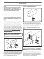
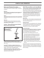
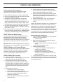
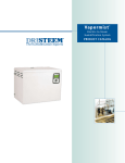
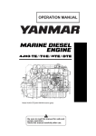
READ AND SAVE THESE INSTRUCTIONS
DRI-STEEM
CRUV
TM
ELECTRIC STEAM HUMIDIFIER
Installation Instructions
and
Maintenance Operations Manual
For Toll-Free Customer Support,
Call: 1-800-328-4447
ETL LISTED
cETL LISTED
TABLE OF CONTENTS
TO THE PURCHASER AND THE INSTALLER
Thank you for purchasing our CRUVTM humidification equipment. We have designed and built this equipment to give
you total satisfaction and many years of trouble-free service. Proper installation and operating practices will assure
you of achieving that objective. We therefore urge you to become familiar with the contents of this manual.
DRI-STEEM Humidifier Company
CRUV Humidifier ......................................................................... 3
Installation .................................................................................. 4
Specifications, Capacities, and Dimensions ............................ 6
Start-up and Operation ............................................................... 8
Maintenance ................................................................................ 9
Trouble-Shooting Guide ............................................................. 10
Replacement Parts ...................................................................... 14
Maintenance Service Record ..................................................... 19
Two-Year Limited Warranty ........................................................ 20
2
CRUVTM HUMIDIFIER
Figure 3-1: The CRUV Humidifier
(CRUV 6-25 shown, CRUV 2, 4, 30, and 34 not shown)
Probe
Steam outlet
Heater terminal cover
Strainer
Cover
Fill
valve
Cover
bolts
Over
flow
CRUV Humidifier
This humidifier is designed to be used with either softened or unsoftened water (softened water will greatly
reduce humidifier maintenance and improve overall
system performance). The probe-type level control
system requires water conductivity of at least 100
micromhos/cm (2 grains/gal or 34.2 mg/liter) to function,
and therefore, will not operate with demineralized water.
For humidification using demineralized water, see
CRUV-DI below.
Heater
element
Electric drain
Tank
temperature
sensor
OM-770-1
Figure 3-2: The CRUV-DI Humidifier
(CRUV-DI 6-25 shown, CRUV-DI 2, 4, 30, and 34 not shown)
Float switch
Steam outlet
Heater terminal cover
Cover
Water
supply
Over
flow
CRUV-DI Humidifiers
The evaporating chamber of this humidifier is
constructed of corrosion-resistant stainless steel alloy
to resist the corrosive effects of mineral-free water.
Since the CRUV-DI humidifier is designed for use with
deionized or RO demineralized water, there is no need to
clean the unit, although an annual inspection of the
evaporating chamber is recommended.
Cover
bolts
Heater
element
½" SST
ball valve
Tank temperature sensor
OM-770-2
3
INSTALLATION
Locate the CRUVTM humidifier near an electric power
source, water supply and a drain. Verify that sufficient
room is provided for a water seal in the drain piping. Refer
to Figure 4-3.
Examples of Installation in an Air Stream
Figure 4-1: Installation in an Air-Conditioning Unit
In an Air-Conditioning Unit
When installing a humidifier inside an air conditioning unit,
provide adequate support; allow easy access for removing
and servicing the evaporating chamber, and provide
adequate clearance to install the vapor hose and dispersion tube (see figure 4-1) and water seal. Refer to page 6
for mounting hole locations.
In a Duct
When installing the dispersion tube in a duct, allow for a
continuous pitch of the vapor hose back to the evaporating
chamber. Otherwise, use a water seal and drain (see
examples in figures 4-2 and 5-1). The dispersion tube can
also be placed vertically in the duct with some models
(see figure 5-2).
Place the control cabinet or electrical sub-panel in a
grounded protective metal enclosure and mount in a dry
and accessible location.
If draining the evaporating chamber by gravity is not
possible, use a small condensate lift pump, rated to pump
212° F/100°C water.
OM-2008
Figure 4-2: Horizontal Dispersion Tube
Figure 4-3: Piping for the CRUV
Duct
Water seal must
not be above
bottom of frame
Vapor Hose
12" (305 mm)
Note: provide 1"
(25 mm) air gap to
eliminate back
siphonage
Floor drain
OM-2006
Horizontal mounting of dispersion tube in a duct, connected
via vapor hose to a wall-mounted CRUV humidifier.
4
Sanitary
sewer
OM-2003-1
INSTALLATION
Piping
Water make-up piping should be of corrosion-resistant,
code-approved material (copper, steel, or plastic). The
final connection size is ¼" NPT. In cases where water
hammer is possible, a shock arrestor should be
considered.
Figure 5-2: Vertical Dispersion Tube
Duct
Drain piping should be of code approved material
(copper, steel, or plastic rated for 212°F/100°C minimum).
The ¾" O.D. copper sweat connection should not be
reduced in size. (See figure 4-3).
If there is no sewer available for drainage, the unit can
be piped for manual drainage. Consult factory for instructions.
Wiring
The CRUVTM is designed for a single source of electric
power supply. Future tank removal will be easier if plugs or
quick connects and extra long conduits are used to
provide electrical power to components from subpanel.
Wiring must meet all electrical codes, the current characteristics, and capacity requirements should be checked
against the nameplates. The electrical subpanel should be
mounted in a location convenient for service. Wiring must
be in accordance with all governing codes, and with the
humidifier wiring diagram. The wiring diagram(s) are
shipped loose with the unit. The wiring between the control
cabinet and humidifier must be rated at 105°C, 600V.
Caution: Only qualified electrical personnel
should perform installation procedures.
OM-775-1
The dispersion tube can be mounted vertically in the duct.
Note: When dispersion tube is more than 10' (3 m) from unit,
insulated, 1½" (38 mm) diameter minimum rigid tubing or
pipe should be used instead of vapor hose. This application
is not recommended for CRUV-10 through CRUV-34.
Figure 5-3: RAPID-SORB® Rapid Absorption Tube
Bank
Duct
Figure 5-1: Horizontal Dispersion Tube Lower Than
Humidifier
Duct
6" (152 mm)
Tee
OM-831-1
8"
(200 mm)
Water Seal
OM-774-1
When horizontally mounting the dispersion tube in an air
stream that is located lower than the CRUV humidifier a water
seal (to prevent steam from escaping at the open drain) must
be provided in the drain line and line extended to open drain,
as shown, to drain the condensate. A multiple dispersion
tube bank must be used with a CRUV-30 or CRUV-34
because of its high output (see figure 5-3).
When rapid absorption is extremely critical, a RAPID-SORB
multiple-tube bank can provide 100% steam absorption within
three feet or less - at any duct temperature. A multiple tube or
RAPID-SORB dispersion system is required for CRUV-30 or
CRUV-34.
For complete information on calculating the number of
dispersion tubes required to satisfy steam absorption
distance requirements, consult your sales representative,
the DRI-STEEM factory, or use DRI-STEEM's DRI-CALC®
Humidification Sizing and Selection Software.
5
SPECIFICATIONS, CAPACITIES, AND DIMENSIONS
CRUVTM Mechanical/Electrical Specifications
A
Top view
Side Elevation
(CRUV 25, 30, 34)
A
15.0
F
D
G
OM-2004
4.25
H
OM-759-1
End Elevation
E
0.250
Table 6-1: CRUV Dimensions (in inches)
Model
i n.
CRUV/CRUV-DI - 2 & 4
F
CRUV/CRUV-DI - 6, 8 & 10
CRUV/CRUV-DI - 12 & 16
CRUV/CRUV-DI - 21, 25, 30 & 34
A
B
C
D
E
F
G
H
14.35
15.50
9.00
7.88
11.50
11.44
2.38
6.6
167.7
mm
364
394
229
200
292
291
60.33
i n.
14.35
16.00
14.38
8.88
16.88
12.94
5.05
9.3
mm
364
406
365
225
429
329
128.27
236.2
i n.
14.35
16.00
14.38
10.68
16.88
14.75
5.05
9.3
mm
364
406
365
2 71
429
375
128.27
236.2
i n.
14.35
16.00
14.38
12.25
16.88
16.25
5.05
9.3
mm
364
406
365
311
429
413
128.27
236.2
NOTE: Charts shown here can be used for CRUV-DI sizing.
G
4.25
OM-2002
C
Table 6-2: CRUV Mechanical/Electrical Specifications and Capacities
CRUV-2
CRUV-DI-2
CRUV-4
CRUV-DI-4
CRUV-6
CRUV-DI-6
CRUV-8
CRUV-DI-8
CRUV-10
CRUV-DI-10
CRUV-12
CRUV-DI-12
CRUV-14
CRUV-DI-14
CRUV-16
CRUV-DI-16
CRUV-21
CRUV-DI-21
CRUV-25
CRUV-DI-25
CRUV-30
CRUV-DI-30
CRUV-34
CRUV-DI-34
Output/hour
(lbs/gal/kg)
6/.7/2.7
12/1.4/5.4
18/2.2/8.2
24/2.9/10.9
30/3.6/13.6
36/4.4/16.4
42/5/19.1
48/5.8/21.8
63/7.7/29.0
75/9.0/34.0
90/10.9/41.4
102/12.2/46.3
Operating wt.
(lbs/kg)
43/20
44/20
83/38
83/38
100/45
100/45
85/39
100/45
113/51
113/51
117/53
117/53
Shipping wt.
(lbs/kg)*
18/8
19/9
40/18
40/18
44/20
44/20
37/18
44/20
47/21
47/21
51/23
51/23
16.7
-
-
-
-
-
-
-
-
-
-
-
Amps at:
120v/1ø
208v/1ø
9.6
19.2
28.8
38.5
-
-
-
-
-
-
-
230v/1ø***
8.0
16.0
24.0
31.9
39.9
-
-
-
-
-
-
-
240v/1ø
8.3
16.7
25.0
33.3
41.7
-
-
-
-
-
-
-
480v/1ø
4.2
8.3
12.5
16.7
20.8
25.0
29.2
33.3
43.8
-
-
-
600v/1ø
3.3
6.7
10.0
13.3
16.7
20.0
23.3
26.7
35.0
41.7
-
-
208v/3ø
-
16.7**
25.0**
33.3**
29.1**
33.3
38.9
44.4
-
-
-
-
240v/3ø
-
14.4**
21.7**
28.9**
25.3**
28.9
33.7
38.5
-
-
-
-
400v/3ø
-
8.7**
13.0**
17.3**
15.2**
17.3
20.2
23.1
30.3
36.1
43.3
40.9
480v/3ø
-
7.2**
10.8**
14.4**
12.6**
14.4
16.8
19.2
25.3
30.1
36.1
600v/3ø
-
5.8**
8.7**
11.5**
10.1**
11.5
13.5
15.4
20.2
24.1
28.9
32.7
kW
2.0
4.0
6.0
8.0
10.0
12.0
14
16.0
21.0
25.0
30.0
34.0
* Add 9 lbs (4 kg) to total weight for models with pre-wired subpanel.
** For wire sizing, highest leg draw is due to current unbalance in some cases.
*** Output capacity and kW derate of 7%.
6
START-UP AND OPERATION
Start-up and Checkout Procedures
LW417 Electronic Water Level Control Module
After the system has been properly installed and connected to both electrical and water supplies, it may then
be started.
When the power is activated, the solenoid-operated water
fill valve will open, filling the evaporating chamber. Filling
will continue until water reaches level A (figure 8-1), at
which time the fill valve will close. To ensure that a water
seal is created in the field-installed water seal, disconnect
probe plug and cable from probe rod assembly (located
on the top of the tank), allowing the fill valve to reenergize and overfill humidifier tank. This process will
take only seconds; probe plug and cable must then be
reconnected. A call for humidity will then energize the
heating element.
Mounting
Check mounting to see that the unit is level and securely
supported before filling with water. Refer to page 6 for
mounting hole locations.
Piping
Verify that all piping connections have been completed as
recommended and that water pressure is available. Refer
to page 5.
Electrical
Verify that all wiring connections have been made in
accordance with all governing codes and the enclosed
wiring diagram. Refer to page 5.
Caution: Only qualified personnel should
perform start-up procedure.
Heater Protection
Should the water line ever drop below level C, the heaters
are de-energized and remain OFF until the water line has
been restored to level C. This feature provides heater
protection in the event of a low-water condition.
Drain/Flush Feature
This control module contains an integral electronic timer
which tracks the humidifying time of the unit. When this
accumulated time reaches what has been set in the
timer, the drain/flush cycle is activated.
Upon activation, the following sequence occurs:
Figure 7-1: Electronic
Probe Control for
Maintaining Proper
Water Level (CRUVTM)
A
B
C
OM-211-2
A simple three-probe conductivity sensor cycles a
solenoid-operated water fill valve to maintain the proper
water levels.
TM
Water Refill
During operation, when the water line drops below level B
the fill valve opens, and remains open until the water line
returns to level A (figure 7-1).
The CRUV humidifier is available with either the
standard LW 417 Electronic Water Level Control Module
or the optional VAPOR-LOGIC®3 microprocessor control
system. If your system is equipped with the
VAPOR-LOGIC3 system, see the VAPOR-LOGIC3
Operations and Maintenance Manual for more information.
Then continue reading this manual beginning at the
maintenance section on page 9.
1. The drain valve opens and begins to drain surface
water and minerals from the evaporating chamber.
2. When the height of the water drops below level "C",
this will allow the flush cycle to start.
3. Once the flush period starts the drain and fill valves
will remain open 1-3 minutes, flushing the chamber.
4. After 10 minute Drain/Flush feature, the drain valve
then closes, the chamber refills, and the fill valve
closes. The timer resets and the unit resumes normal
operation.
The electronic timer comes factory-set for drainage after
40 hours of operation. Alternate settings of 20 hours and
80 hours are available. See wiring diagram(s) attached to
unit for timer board location and instructions for changing
the timer setting.
7
START-UP AND OPERATION
Test Cycling the Drain/Flush System
The level control board incorporates a set of slide
switches which are marked 1 through 8. To test:
1. Place "SWI" slide switches 1,2 and 3 to off position.
2. Set the humidistat high enough so that unit will remain
“on call” for at least 15 minutes.
3. After about 2 minutes of operation, activation will
take place, causing the drain valve to open. The
water level will then drop to level C (see figure 7-1 on
page 7) and allow the fill valve to open. Both valves
will remain open for the remainder of Auto/Flush period.
4. The drain valve will then close, and the water level
will rise to level A (see figure 7-1 on page 7), causing
the fill valve to close.
5. Once the test cycle is complete, return slide switches
back to the desired operating mode. Failure to do so
will result in a drain/flush cycle every 2 minutes.
CRUVTM Make-up Water Piping
If the water pressure is above 60 psi (414 kPa) and/or
water hammer would be objectionable, a pressurereducing valve or shock arrester should be installed.
Even though the humidifier has an internal 1" (25 mm) air
gap, some local codes may require a vacuum breaker.
Important: Minimum water supply pressure is 25 psi (170
kPa). Maximum water supply pressure is 80 psi (552 kPa).
CRUV-DI Water Level Control System
The basic float valve water level system and float switch
circuit for heater protection in the event of a low-water
condition is common to all DI humidifiers and can be
found in the wiring diagram shipped with the unit.
CRUV-DI Start-Up Procedure
a) Adjust humidistat to "call" setting.
b) Open shut-off valve on water supply line. Unit should
begin filling with water through the fill valve.
c) Shortly before the fill valve shuts off, the float
operated heater cut-off switch will "make." When
this switch makes, the heating element contactor(s)
will be actuated. A time delay relay circuit prevents
contactor chatter due to bouncing of heater cut-off
float.
d) Check heater cut-off circuit.
1. Close manual valve on water supply.
2. Open drain valve and start draining unit.
3. When water level drops past switching level on
the heater cut-off float, the heating element
contactor(s) will drop out.
4. When step 3 has been satisfactorily completed,
close drain valve.
8
e) Check function of field-installed safety controls,
such as the fan proving switch. Contactor(s) should
drop out when the proving switch is "open."
f) Check heater draw by testing and recording voltage
and amperage in each phase. Readings should
match name plate readings; name plate is located on
the humidifier housing.
g) Inspect installations for steam or air leaks while
operating the humidifier. Any leaks should be
sealed.
Inspect after first three months of duty. The best way to
determine how often your particular system will need
maintenance is to remove the cover and inspect it after
its first three months of duty. Potable water carries a
variety of minerals and other materials in a mix that varies
from location to location. This variation in water quality,
combined with the hours of operation and duty cycle, will
determine your own unique maintenance schedule.
Water quality makes a difference
1. Light to moderately hard water (2 to 10 grains/gallon
or 34.2 to 171 mg/1 hardness)
• annual cleaning
2. High mineral content water (more than 10 grains/
gallon or 171 mg/1 hardness)
• cleaning frequency determined by use and water
quality
• periodic drain and flush cycles
3. DI/RO water (Model VMDI)
• no regular cleaning required (although regular
inspections are advised)
• no drain and flush cycles required
• the presence of chlorides in DI water will
eventually cause pitting and failure of the tank
and its components
4. To dramatically reduce mineral accumulation inside
the evaporating chamber, softening of the makeup water
recommended. (Solids like silica are not removed in the
the softening process.)
MAINTENANCE
CRUVTM Humidifier
(Non-DI humidifiers with either the LW 417 or
VAPOR-LOGIC®3 Control Systems)
Mineral Precipitate
As evaporation takes place in the CRUV humidifier, some
of the minerals dissolved in the water precipitate out and
float on the water surface. The minerals not removed by
the skimmer will settle to the bottom of the evaporating
chamber.
Cleaning the Evaporating Chamber
The heating element itself is self-cleaning. The mineral
buildup on the element flakes off after reaching a thickness of about 1/16" (2 mm), and settles to the bottom of
the chamber.
Long heater element life can be expected when the
operation of the humidifier is observed for a few weeks
following initial start-up. By observing the mineral build-up
rate, the frequency of both drain/flush use and manual
cleaning can be determined and adjustments made.
CAUTION: Before this mineral scale builds up on the
underside of the heating element, it must be removed.
Failure to do so may result in premature heater burnout.
The CRUV humidifier is designed for convenient cleaning
and maintenance.
To Inspect and Service:
1. Shut off all eletrical power to humidifier. Drain
evaporating chamber by manually opening DRAIN
valve. Do this by moving lever on valve to MANUAL
position and lock in place. If the tank is hot, cool it
down by opening the manual valve on the side of the
tank. The float valve will open allowing cool water to
run into the tank until it is cool enough to handle.
2. Unscrew probe-rod assembly. Scale should flake off
easily. Build-up on tips should be scraped off to
remove any mineral residue.
3. Remove the tank cover and wet vac minerals out of
tank (recommended).
4. To remove tank for cleaning, disconnect drain line
union, fill valve supply line, electrical connections to
drain, (disconnecting field wiring in conduit is NOT
recommended,) thermal trip, heaters, fill valve, and
probe. Disconnect steam hose from top of tank and
remove mounting bracket fasteners.
5. Remove evaporating chamber and clean.
6. Install the probe and probe plug assembly. Verify
that ground wire is connected.
7. Replace tank cover, making sure tank is sealed tight.
8. Reconnect drain line union, fill valve supply line,
electrical connections to drain, thermal trip, heaters,
fill valve, and probe. Connect steam hose to top of
tank.
9. Verify drain valve lever is in AUTO position.
10. The CRUV humidifier is again ready to humidify.
Off-Season Shutdown
1. Switch off power.
2. Turn off water supply to make-up valve.
3. Drain evaporating chamber and clean if necessary
(see steps 1 through 9 above).
4. Leave chamber dry, power OFF and water shut-off
valve closed until the next humidification season.
CRUV-DI Humidifier
To Service
1. Manually open drain valve.
2. Allow time for the evaporating chamber to cool. If the
tank is hot, cool it down by moving the valve lever
located on the back of the drain valve to the manual
open position – the fill valve will eventually open
allowing cool water to run through the tank until it is
cool enough to handle.
3. Shut off electrical power to unit.
4. Shut off water supply to make-up valve.
5. Make sure evaporating chamber is drained.
6. Unscrew four cover bolts and remove cover.
7. Check operation of float valve and low-water cut-out.
8. Inspect heating elements.
9. Inspect evaporating chamber and clean if necessary.
10. Inspect cover gasket, and replace if necessary.
11. Replace chamber cover.
12. Verify drain valve is in the closed position.
13. Open water supply valve and turn on electric power.
14. CRUV-DI humidifier is again ready to humidify.
15. If necessary, remove tank as follows:
Remove flexible vapor hose from tank. Close drain
valve. Disconnect unit from drain and supply water
lines. DO NOT DISCONNECT ANY OF THE
ELECTRICAL CONDUITS.
Off-Season Shutdown Procedure
1. Switch off electrical power to unit.
2. Check overall appearance of unit.
3. Shut off water supply to make-up valve.
4. Drain evaporating chamber by manually opening
drain valve.*
5. Visually check electrical components of subpanel.
6. Leave chamber dry, power off, and water shut-off
valve closed until the next humidification season.
* With VAPOR-LOGIC3 option, the evaporating chamber is automatically drained after 72 hours without a call for humidity when the endof-season drain option is ordered.
9
CRUVTM TROUBLE-SHOOTING GUIDE
MODULE INDICATING
LIGHTS
PROBLEM FULL READY DRAIN
WATER
Humidifier will
not heat
Humidifier will
not fill
Humidifier does
not stop filling
(LW417 Electronic Water Level System Only)*
POSSIBLE CAUSE
RECOMMENDED ACTION
Off
Off
Off
Control transformer
Verify control voltage across secondary
leads of transformer. Reset transformer
circuit breaker.
On
On
Off
Humidistat is not calling
Set humidistat to call. Inspect for faulty
humidistat.
Safety controls open
Check safety controls, air flow switch, high
limit humidistat, etc.
Faulty control board
Verify control voltage between terminals.
Probe head deterioration**
Replace probe head.
No water pressure at valve.
Check water supply/shut off valves.
Faulty water fill valve
Verify action of fill water solenoid valve by
turning control module switch from standby
to normal op. Audible click should be
heard as solenoid operates.
Plugged strainer
Check strainer.
Plugged valve
Check valve.
Faulty control board
Verify control voltage across input terminals
"B&W"
Lack of tank to probes
electrical continuity. Water
conductivity 100
microSiemens/cm (2 gr/gal) min.
Jumper wires violet, orange then brown to
ground. If water stops, verify tank ground;
check water supply conductivity; then
consult factory.
Fill valve is stuck open
Check valve for foreign matter.
Drain Valve not closed
Fill valve installed backward
Check for correct water flow through valve
note arrow.
Off
Off
Off
Off
Off
Off
Off
Off
On
Auto-drain mode
10 Minute must complete first.
On
On
Off
Electric drain valve not
seating
Correct cause of leakage or replace valve.
On
On
Off
Fill valve is stuck open
Check valve for foreign matter.
Unit short cycles On & Off
On
Off
Probes may be incorrectly
wired or need cleaning
Confirm that unit is wired per diagram.
Clean probe rod tips with steel wool.
Reduced or no
output even
though water
is at the proper
level
On
Off
Heater malfunctioning
Verify that proper voltage is being applied to
heaters. Check heater (amp draw and
compare to wiring diagram ratings).
Malfunctioning control
system
Heater contactor not functioning--replace.
Service fuses blown. Auxiliary limit controls
not allowing system to operate (dust humidistat, air flow proving switch, etc.). Reset,
replace or calibrate as required. Faulty or
inaccurate humidistat, replace or calibrate.
Low output
On
*For VAPOR-LOGIC3 trouble-shooting, see the VAPOR-LOGIC3 Operations and Maintenance Manual.
**Probe rod corrosion or probe head material aging may cause level control system failure. This generally does not occur in the first two years of operation.
10
CRUVTM-DI TROUBLE-SHOOTING GUIDE
PROBLEM
POSSIBLE CAUSE
RECOMMENDED ACTION
Humidifier will
not heat
Control transformer
Verify control voltage across secondary leads of
transformer. Reset transformer circuit breaker.
Humidistat is not calling
Set humidistat to call. Inspect for faulty humidistat.
Safety controls open
Check safety control. (Air flow switch, high limit
humidistat, etc.)
Low water float switch
Verify control voltage from float switch and transformer
secondary common.
No water pressure at valve
Check manual water supply. Valve, minimum 25 psi
water pressure.
Malfunctioning water float valve
Check to make sure that valve float & stem moves
freely.
Plugged float valve
Check float valve seat.
Open drain valve
Obstruction in drain valve will not allow complete
closure, clean or replace valve.
Manual drain valve not closed
Close drain valve.
Malfunctioning float valve
Float ball has water leak. Float valve seat defective,
replace.
Water passing into overflow
stand pipe
Readjust float valve rod, so water level reaches 1/43/8" from overflow edge when water is at ambient or
cold state. Excessive water pressure, 80 psi maximum.
Float valve stuck
Obstruction will not allow float valve to seat properly,
clean or replace with new seat.
Heater malfunctioning
Verify that proper voltage is being applied to heaters.
Check heaters (amp draw and compare to wire
diagram ratings).
Malfunctioning control system
Heater contactor not functioning, replace. Service
fuses blown. Auxiliary limit controls not allowing
system to operate (duct humidistat, air flow proving
switch, etc.). Reset, replace, or calibrate as required.
Faulty or inaccurate humidistat, replace or calibrate.
Time delay/interlock relays
Relay delay on time is 10-15 seconds. Check relays.
Low water cut-off switch
Check for proper operation.
Humidifier will
not fill
Water float valve
does not close
Reduced or no
output even
though water is at
the proper level
11
CRUVTM TROUBLE-SHOOTING GUIDE (VAPOR-LOGIC®3 only)
PROBLEM
POSSIBLE CAUSE
RECOMMENDED ACTION
Incorrect or nonexistent supply
voltage to unit
Check main line safety switch.
Check main line fuses.
Check for proper supply voltage.
Incorrect or nonexistent control
voltage
Reset control transformer circuit breaker.
Check for 24 VAC control circuit voltage at T-1 and T-2 on the
control board.
Humidistat not calling
Set humidistat to call. Inspect for faulty humidistat.
Safety controls open
Check safety controls, air flow switch, and high limit humidistat.
No water pressure at valve
Check water supply/shut-off valves.
Faulty water fill valve
Check for 24 volts at the fill valve.
Plugged strainer
Check strainer.
Plugged valve
Check valve.
Faulty control board
Verify control voltage across the fill valve output.
Lack of tank to probe electrical
continuity. Water conductivity must
be 100 microSiemens/cm (2 gr/gal)
Add salt to the tank. If this solves the problem, consult factory for
further advice.
Fill valve stuck open
Check valve for foreign matter.
Drain valve not closed
Fill valve installed backward
Check for correct water flow through valvee by noting arrow.
Autodrain mode
Humidifier may be in periodic drain and flush. Check controller
display.
Electric drain valve not seating
Correct the cause of leakage or replace valve.
Fill valve stuck open
Check valve for foreign matter.
Unit short-cycles.
Controller cycle rate set too low
Review controller cycle set point.
Reduced or no output even
though water is at the
proper level
Heater malfunctioning
Verify that proper voltage is being applied to heaters. Check heater
amp draw and compare to wiring diagram ratings.
Malfunctioning control system
Replace heater contactor if not functioning. Verify auxiliary limit
controls (humidistat, air flow proving switch, etc.) and reset,
replace or calibrate as needed.
Humidifier does not heat.
Humidifier will not fill.
Humidifier does not stop
filling.
Low output
12
*Probe rod corrosion or probe head material aging may cause level control system failure. This generally does not occur in the first
two years of operation.
CRUVTM-DI TROUBLE-SHOOTING GUIDE (VAPOR-LOGIC®3 only)
PROBLEM
Humidifier will not heat.
Humidifier will not fill.
Humidifier does not stop
filling.
Reduced or no output even
though water is at the proper
l e ve l .
POSSIBLE CAUSE
RECOMMENDED ACTION
Control transformer
Reset control transformer circuit breaker.
Humidistat is not calling
Set humidistat to call. Inspect for faulty humidistat.
Safety controls open
Check safety controls, air flow switch, high limit humidistat, etc.
Low water cutoff
Check at board 32 and 33. Measure 0 volts for closed switch,
approximately 2.5 volt for A.C. open switch.
No water pressure at valve
Check manual water supply. Valve, minimum 25 psi water pressure.
Malfunctioning float switch
Check to make sure that float moves freely on stem.
Plugged fill valve
Check fill valve inlet.
Open drain valve
Obstruction in drain valve will not allow complete closure. Clean or
replace valve.
Manual drain valve not closed
Close drain valve.
Fill valve stuck open
Check valve for foreign matter, water-logged float, broken float am,
or worn valve stopper.
Heater malfunctioning
Verify that proper voltage is being applied to heaters. Check heater
(amp draw and compare to wiring diagram ratings).
Malfunctioning control system
Heater contactor not functioning, replace. Service fuses blown.
Auxiliary limit controls not allowing system to operate (dust
humidistat, air flow proving switch, etc.) Reset, replace or calibrate
as required. Faulty or inaccurate humidistat, replace or calibrate.
13
REPLACEMENT PARTS
Table 14-1: CRUVTM 2 through 16
Item
Description
Qty
Part No.
1
1/4-20 X 1" lg phillips head bolt
4
700300-013
2
thermo cut-out
1
409560-001
3
heater terminal cover
1
*
4
tank cover
1
*
5
heater element
1
409600 *
6
probe assy with conduit and fitting
1
406050-100
7
probe assy gasket
1
309750-003
8
probe assy, CRUV 2-4
1
406270
8
probe assy, CRUV 6-34
1
406275
9
3/4" electric valve 24v
1
505400-001
10
tank weldment
1
*
11
1/4" solenoid valve 24v w/flying leads
1
505084
12
3/4" ID hose
1
307020-002
700560-075
13
3/4" hose clamp
4
14
1/4-20 nut assy CRUV/CRUV-DI 2-4
4
700650
14
1/4-20 nut assy CRUV/CRUV-DI 6-34
2
700650
15
cover to tank gasket
1
*
16
#8 external tooth washer pltd
2
700200-003
17
#8-32 hex nut pltd
4
700200-002
18
#8-32 X1/2" phillips head screw
2
700170-007
19
1/4" lock washer
4
700351-025
20
nylon probe housing, CRUV
1
308500
* Specify humidifier model and serial numbers when ordering replacement parts.
OM-779-5
14
REPLACEMENT PARTS
Table 15-1: CRUVTM 21, 25, 30 and 34
Item
Description
Qty
Part No.
1
1/4-20 X 1" lg phillips head bolt
4
700300-013
2
thermo cut-out
1
409560-001
3
heater terminal cover
1
*
4
tank cover
1
*
5
heater element, 2kW 120v
*
409600 *
6
probe assy with conduit & fitting
1
406050-100
7
probe assy gasket
1
309750-003
8
probe assy, CRUV 6-34
1
406275
9
3/4" electric valve 24v
1
505400-001
10
tank weldment
1
*
11
1/4" solenoid valve 24 v w/flying leads
1
505084
12
3/4" ID hose
1
307020-002
13
3/4" hose clamp
4
700560-075
14
1/4-20 nut assy CRUV/CRUV-DI 6-34
2
700650
15
cover to tank gasket
1
*
16
#8 external tooth washer pltd
2
700200-003
17
#8-32 hex nut pltd
4
700200-002
18
#8-32 X 1/2" phillips head screw
2
700170-007
19
1/4" lock washer
4
700351-025
20
nylng probe housing, CRUV
1
308500
* Specify humidifier model and serial numbers when ordering replacement parts.
OM-779-6
15
REPLACEMENT PARTS
Table 16-1: CRUVTM-DI 2 through 16
Item
D escription
Qty
Part N o.
1
1/4-20 X 1" l g phi l l i ps head bol t
4
700300-013
2
thermo cut-out
1
409560-001
3
heater termi nal cover
1
*
4
fl oat assy
1
505310
5
1/4" l ock w asher
4
700351-025
6
tank cover
1
*
7
heater el ement
*
409600 *
8
fl oat sw i tch assy
1
9
probe assy gasket
1
10
seal ri ng 1/4" 18 npt 303 sst
1
306365
11
1/2" sst bal l val ve assy
1
505000-003
11
end-of-season drai n val ve assy (not
sh o w n )
1
505086-003
12
tank w el dment
1
*
13
ori fi ce, .041 fi l l model s 4-16
1
160229-041
14
nyl on probe housi ng
1
308500
309750-004
15
3/4" ID hose
1
307020-002
16
3/4" hose cl amp
4
700560-075
17
1/4-20 nut assy C RU V/C RU V-DI 2-4
4
700650
17
1/4-20 nut assy C RU V/C RU V-DI 6-16
2
700650
18
cover to tank gasket
1
*
19
#8 external tooth w asher pl td
2
700200-003
20
#8-32 hex nut pl td
6
700200-002
21
pi pe w el d, fi l l val ve
1
160215
22
#8-32 X 1/2" phi l l i ps head screw
2
700170-007
* Specify humidifier model and serial numbers when ordering replacement parts.
OM-779-7
16
REPLACEMENT PARTS
Table 17-1: CRUVTM-DI 21, 25, 30 and 34
Item
Description
Qty
Part No.
1
1/4-20 X 1" lg phillips head bolt
4
700300-013
2
thermo cut-out
1
409560-001
3
heater terminal cover
1
*
4
float assy
1
505310
5
1/4" lock washer
1
700351-025
6
tank cover
1
*
7
heater element
*
409600 *
8
float switch assy
1
9
probe assy gasket
1
309750-004
10
seal ring 1/4" 18 npt 303 sst
1
306365
11
1/2" sst ball valve assy
1
505000-003
11
end-of-season drain valve assy (not
sh o w n )
1
505086-003
12
tank weldment
1
*
13
orifice, .052 fill models 21-34
1
160229-052
14
nylon probe housing
1
308500
15
3/4" id hose
1
307020-002
16
3/4" hose clamp
4
700560-075
17
1/4-20 nut assy CRUV/CRUV-DI 6-34
2
700650
18
cover to tank gasket
1
*
19
#8 external tooth washer pltd
2
700200-003
20
#8-32 hex nut pltd
6
700200-002
21
pipe weld, fill valve
1
160215
22
#8-32 X 1/2" phillips head screw
2
700170-007
* Specify humidifier model and serial numbers when ordering replacement parts.
OM-779-8
17
REPLACEMENT PARTS
Table 18-1: CRUVTM Control Cabinet with VAPOR-LOGIC®3
and SSR option
Item
Qty
Part No.
1
main board, VL3
Description
1
408490-001
2
block, din rail stop
5
408252-006
3
terminal, ground
1
408252-010
4
terminal
2
408252-001
5
transformer, 120/280/240/480*
1
408965-001
5
transformer, 600v*
1
408986
6
SSR, 480 VAC 50 amp 1 pole
2
408677-002
7
contactor, 60 amp*
1
407001-021
7
contactor, 32 amp*
1
408991
8
3 pole 3Ø power block*
2
408300-002
8
2 pole 1Ø power block*
2
408300-001
9
fan, 24 volt
1
408677-001
* Specify humidifier model and serial numbers when ordering.
OM-1017C
Table 18-2: CRUVTM Control Cabinet with VAPOR-LOGIC®3 option
Item
Description
Qty
Part No.
1
su b p a n e l , 1 3 " X 1 5 "
1
165720-003
2
DIN rail, 2-1/4" long
2
167765-0022
3
DIN rail, 4-1/2"
1
167765-0045
4
contractor, 32A*
1
407001-020
4
contractor, 60A*
1
407001-021
5
transformer, 600V*
1
408986
5
transformer, 120/240/480/208*
1
408965-001
6
3 pole 3Ø power*
1
408300-002
6
2 pole 1Ø power*
1
408300-001
7
block, DIN rail stop
4
408252-006
8
terminal
2
408252-001
9
terminal, ground
1
408252-010
10
ground lug, L-70 6-8 GA CP-4
1
409250-018
11
screw, #6-32 X 1-1/4" type F
2
700100-002
12
screw, #8-32 X .38 phillips type F
8
70170-001
13
screw, #6-32 X .75 phillips type F
6
700100-001
14
standoff, metal #8 X 3/8"
6
409592
15
nut hex #6-32 pltd
6
700100-003
16
microprocessor board
1
408490-001
17
star washer, #8-32 external tooth
1
700200-003
18
label, copper wire
1
805050
19
label, machine ground
1
800010
20
label, ground symbol
1
806810
21
label, protective ear thing
1
806820
cruvpnlasm-1
* Specify humidifier model and serial numbers when ordering.
OM-1017B
18
MAINTENANCE SERVICE RECORD
DATE INSPECTED
PERSONNEL
OBSERVATION
ACTIONS PERFORMED
19
TWO-YEAR LIMITED WARRANTY
DRI-STEEM Humidifier Company (“DRI-STEEM”) warrants to the original user that its products will be free
from defects in materials and workmanship for a period of two (2) years after installation or twenty-seven (27)
months from the date DRI-STEEM ships such product, whichever date is the earlier.
If any DRI-STEEM product is found to be defective in material or workmanship during the applicable warranty
period, DRI-STEEM’s entire liability, and the purchaser’s sole and exclusive remedy, shall be the repair or
replacement of the defective product, or the refund of the purchase price, at DRI-STEEM’s election. DRISTEEM shall not be liable for any costs or expenses, whether direct or indirect, associated with the installation, removal or reinstallation of any defective product.
DRI-STEEM’s limited warranty shall not be effective or actionable unless there is compliance with all installation and operating instructions furnished by DRI-STEEM, or if the products have been modified or altered
without the written consent of DRI-STEEM, or if such products have been subject to accident, misuse,
mishandling, tampering, negligence or improper maintenance. Any warranty claim must be submitted to
DRI-STEEM in writing within the stated warranty period.
DRI-STEEM’s limited warranty is made in lieu of, and DRI-STEEM disclaims all other warranties, whether
express or implied, including but not limited to any IMPLIED WARRANTY OF MERCHANTABILITY, ANY
IMPLIED WARRANTY OF FITNESS FOR A PARTICULAR PURPOSE, any implied warranty arising out of a
course of dealing or of performance, custom or usage of trade.
DRI-STEEM SHALL NOT, UNDER ANY CIRCUMSTANCES BE LIABLE FOR ANY DIRECT, INDIRECT,
INCIDENTAL, SPECIAL OR CONSEQUENTIAL DAMAGES (INCLUDING, BUT NOT LIMITED TO, LOSS OF
PROFITS, REVENUE OR BUSINESS) OR DAMAGE OR INJURY TO PERSONS OR PROPERTY IN ANY
WAY RELATED TO THE MANUFACTURE OR THE USE OF ITS PRODUCTS. The exclusion applies regardless of whether such damages are sought based on breach of warranty, breach of contract, negligence, strict
liability in tort, or any other legal theory, even if DRI-STEEM has notice of the possibility of such damages.
By purchasing DRI-STEEM’s products, the purchaser agrees to the terms and conditions of this limited
warranty.
U.S. Headquarters:
14949 Technology Drive • Eden Prairie, MN 55344
Phone: (800)328-4447 • (952) 949-2415 • Fax: (952) 229-3200
E-Mail: [email protected] • Web: www.dristeem.com
Europe Office:
Bell Place, Bell Lane • Syresham, Brackley • NN13 5HP, U.K.
Phone: +44 1280 850122 • Fax: +44 1280 850124
E-Mail: [email protected]
Continuous product improvement is a policy of DRI-STEEM Humidifier Company;
therefore, product features and specifications are subject to change without notice.
DRI-STEEM, CRU, RAPID-SORB and VAPOR-LOGIC3 are registered trademarks of the DRI-STEEM Humidifier Company.
Form No. CRUV99-C-0902
20
Copyright © 2002 DRI-STEEM Humidifier Company, Inc.