1
MITEL
3300 IP Communications Platform
Technician’s Handbook
Mitel Communications Director Release 5.0
NOTICE
The information contained in this document is believed to be accurate in all
respects but is not warranted by Mitel Networks™ Corporation (MITEL®). The
information is subject to change without notice and should not be construed in
any way as a commitment by Mitel or any of its affiliates or subsidiaries. Mitel and
its affiliates and subsidiaries assume no responsibility for any errors or omissions
in this document. Revisions of this document or new editions of it may be issued
to incorporate such changes.
No part of this document can be reproduced or transmitted in any form or by any
means - electronic or mechanical - for any purpose without written permission
from Mitel Networks Corporation.
Trademarks
Mitel, SX-2000, SUPERCONSOLE 1000, and SUPERSET are trademarks of
Mitel Networks Corporation.
Windows is a trademark of Microsoft Corporation.
Cisco is a trademark of Cisco Systems, Inc.
VT100 is a trademark of Digital Equipment Corporation.
Java is a trademark of Sun Microsystems Incorporated.
Other product names mentioned in this document may be trademarks of their
respective companies and are hereby acknowledged.
3300 IP Communications Platform
Technician’s Handbook
Mitel Communications Director (MCD) Release 5.0
57011493, Rev A
2011
Trademark of Mitel Networks Corporation
©Copyright 2011, Mitel Networks Corporation
All rights reserved
Table of Contents
Chapter 1 : Getting Started
Purpose of This Handbook ....................................................................................................3
Documentation for Unsupported Controllers ..................................................................3
Symbols Used in the Handbook .....................................................................................3
Safety Instructions ..........................................................................................................3
Start Here Guide ...................................................................................................................5
What You Received ........................................................................................................5
What You Need for Installation .......................................................................................5
Preparation .....................................................................................................................5
Initial Setup .....................................................................................................................6
Install Hardware ..............................................................................................................6
Program System .............................................................................................................6
Install System Software ..................................................................................................6
Maintain System .............................................................................................................7
Install and Replace Units ................................................................................................7
About the 3300 ICP ...............................................................................................................8
3300 ICP Documentation - Mitel eDocs ..........................................................................8
Contacting Mitel ..............................................................................................................9
Chapter 2 : Initial Setup
Connect PC to Controller ....................................................................................................13
PC Requirements .........................................................................................................13
AX, MXe, CX, CXi, CX II and CXi II Controller .............................................................13
Power Up the Controller ...............................................................................................14
MXe Server ...................................................................................................................14
Licensing the MXe Server with AMC ............................................................................23
Setting your DNS Server IP ..........................................................................................24
Verify the Connections ..................................................................................................24
Establish Communication with Controller ............................................................................25
Set Controller RTC IP Address (AX, MXe, CX, CXi, CX II, CXi II) ................................25
Configure System IP Address (MXe Server) ................................................................26
Configure the Layer 2 Switch (AX, MXe, CXi, CXi II) ...................................................26
Configure the Layer 2 Switch (MXe Server) .................................................................27
Enable Licenses and Options .............................................................................................29
Automatic Sync with AMC via MCD Software Installer Tool (Rel 6.0 or later) ..............31
Automatic Sync via System Administration Tool ..........................................................33
Manual License and Options Entry via MCD Software Installer Tool ...........................34
Manual License and Options Entry via System Administration Tool ............................35
Install the Online Help (Optional) ........................................................................................36
Verify the Operation of the Controller ..................................................................................37
Chapter 3 : Installation and Programming
Install Hardware ..................................................................................................................41
Determine Controller Module Configuration .................................................................41
Identify Controller Component Options .........................................................................45
Remove Controller Cover .............................................................................................47
iii
Enter document Title using Variable
Install Controller Modules ............................................................................................ 48
Install Controller Stratum 3 Clock Module .................................................................... 51
Install Controller Hardware .......................................................................................... 51
Rack Mount the Controller ........................................................................................... 51
Wall Mount the CX/CXi and CX II/CXi II Controller ...................................................... 56
Install Service Units and Cabinets ............................................................................... 58
Installing SX-200 Bays ................................................................................................. 62
Install Telephones ........................................................................................................ 64
Install and Configure Music on Hold ............................................................................ 65
Program 5485 IP Paging Unit ...................................................................................... 66
Register IP Devices from the Telephone ..................................................................... 67
Program System ................................................................................................................. 70
Programming Tools ...................................................................................................... 70
Log into the Programming Tools .................................................................................. 71
Configure NSU via IMAT .............................................................................................. 73
Program the Controller DHCP Server (MXe, CX/CXi, CX II/CXi II) ............................. 76
Program LS Trunk Settings via LS Measure Tool ........................................................ 78
Configure Analog Music On Hold/Paging .................................................................... 79
Chapter 4 : Software Installation
About Installing and Upgrading Software ........................................................................... 83
Install System Software Manually ...................................................................................... 85
The MCD Software Installer Tool ....................................................................................... 91
Install the MCD Software Installer Tool ........................................................................ 91
Install System Software using the Software Installer ................................................... 91
Upgrade System Software ................................................................................................. 94
Online Upgrade ............................................................................................................ 94
Offline Upgrade ............................................................................................................ 98
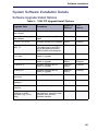
System Software Installation Details ................................................................................ 101
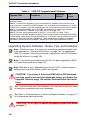
Software Upgrade/Install Options .............................................................................. 101
Upgrading System Software - Notes, Tips, and Cautions .......................................... 102
Change Number of IP User Licenses ........................................................................ 103
Cluster or Dimension Changes .................................................................................. 103
Installing MSL Software on APC (CX/CXi) or APC-CX(i) II (CX II/CXi II) ......................... 105
Installing MSL Software on an MXe Server ...................................................................... 106
Installing System Software on the FTP Server ................................................................. 106
Upgrade to MCD 5.0 and Group Licensing ...................................................................... 107
Upgrade the 3300 ICP Software on the MXe Server ....................................................... 108
Upgrading/Installing with Maximum Elements Change .................................................... 108
Upgrade to Rel 6.0 or later with Flexed Dimensions ........................................................ 110
Apply a Software Patch .................................................................................................... 111
Distributing New Firmware to IP Phones .......................................................................... 112
Load IP Phone Software Remotely .................................................................................. 112
Downgrading to a Previous Software Release ................................................................. 113
iv
Table of Contents
Chapter 5 : Maintenance
Check System ...................................................................................................................117
Check Alarm State ......................................................................................................117
Check System Health .................................................................................................117
Check Controller Hardware Profile .............................................................................118
Maintain VoIP Security ...............................................................................................118
View Logs ..........................................................................................................................119
View Maintenance or Software Logs ..........................................................................119
Collect System Logs ...................................................................................................119
View Logs Remotely, TCP/IP Socket Numbers ..........................................................121
View Login and Logout Audit Logs .............................................................................122
Downloading MXe Server Logs ..................................................................................122
Detect Device Moves for E911 ..........................................................................................123
Monitor Device Moves ................................................................................................123
Detecting Device Moves .............................................................................................126
Viewing Device Connectivity Logs ..............................................................................126
Analyze IP Phone Issues ..................................................................................................127
Power Down the Controller ...............................................................................................129
Perform a System Reset ...................................................................................................129
Back Up a Database .........................................................................................................130
Restore a Database ..........................................................................................................132
Migrate SX-2000 Database Across Platforms ...................................................................136
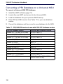
Converting a PRI Database on a Universal NSU ..............................................................138
Export Configuration Data .................................................................................................139
Import Configuration Data .................................................................................................140
Restoring Default Addresses on MXe Server ...................................................................141
Assign Static IP Addresses to IP Phones .........................................................................142
Providing Power Over Ethernet to Devices (CXi/CXi II) ....................................................145
Recover MXe Server .........................................................................................................146
Before You Begin ........................................................................................................146
Install Replacement Hardware ....................................................................................146
Connect Laptop PC and CD/DVD Drive .....................................................................147
Install Mitel Application Server Software ....................................................................148
Configure MAS Parameters ........................................................................................149
Configure Server Manager Fields ...............................................................................150
Reset MXe Server System IP Address to default .......................................................155
Chapter 6 : Install and Replace Units
Component Replacement Notes .......................................................................................159
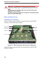
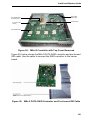
MXe and MXe Server .................................................................................................160
Add or Replace Controller FRUs .......................................................................................166
Controller Modules ............................................................................................................168
Adding or replacing controller modules ......................................................................168
AX Controller ..............................................................................................................169
Controller Module Installation Notes ...........................................................................170
Stratum 3 Clock Module ....................................................................................................173
System i-Button/System ID Module ..................................................................................174
v
Enter document Title using Variable
Analog Main Board ........................................................................................................... 175
MXe ............................................................................................................................ 175
CX/CXi ....................................................................................................................... 176
CX II/CXi II ................................................................................................................. 178
Analog Option Board ........................................................................................................ 179
CX/CXi ....................................................................................................................... 179
CX II/CXi II ................................................................................................................. 180
Configure Embedded Analog Boards ........................................................................ 183
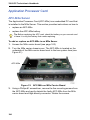
Application Processor Card .............................................................................................. 184
APC-MXe Server ....................................................................................................... 184
APC-CX(i) .................................................................................................................. 188
APC Hard Drive (CX/CXi) .......................................................................................... 192
APC-CX(i) II Assembly ............................................................................................... 194
E2T or RTC Processor ..................................................................................................... 202
Hard Drives ...................................................................................................................... 205
Hard Drive Replacement Overview ............................................................................ 205
CX/CXi ....................................................................................................................... 205
CX II/CXi II (Hard Disk or Solid State Drive) .............................................................. 207
LX ............................................................................................................................... 208
MXe II (Single Hard Disk or Solid State Drive) .......................................................... 209
MXe II/MXe Server (Two Hard Drives) ...................................................................... 210
MXe III (Single Hard Disk or Solid State Drive) ......................................................... 214
MXe III (Two Hard Drives) ......................................................................................... 215
Fan Complex .................................................................................................................... 218
MXe/MXe Server ........................................................................................................ 218
AX .............................................................................................................................. 219
CX II/CXi II ................................................................................................................. 220
Power Supply Unit ............................................................................................................ 221
MXe, AX ..................................................................................................................... 221
ASU II ......................................................................................................................... 221
Redundant Power Supply ................................................................................................. 222
AX, MXe, MXe Server ................................................................................................ 222
RAID Controllers .............................................................................................................. 223
MXe II/MXe Server .................................................................................................... 223
MXe III ....................................................................................................................... 226
Line Cards ........................................................................................................................ 231
AX .............................................................................................................................. 231
ASU II ......................................................................................................................... 231
Controller Card (AX) ......................................................................................................... 232
Flash Cards (AX) .............................................................................................................. 233
Memory Module (CX, CXi, AX) ......................................................................................... 235
Install Cabinet FRUs ........................................................................................................ 236
Appendix A : Hardware Reference
System Configurations ..................................................................................................... 239
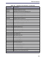
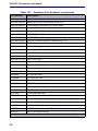
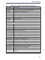
Controller Hardware Details ............................................................................................. 240
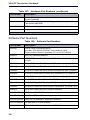
Controller Cabinet Numbering ................................................................................... 247
T1/E1 Combo Card .................................................................................................... 248
vi
Table of Contents
Dual T1/E1 Framer .....................................................................................................250
Quad BRI Framer .......................................................................................................250
Analog Board (CX/CXi, CX II/CXi II, and MXe Controllers) ........................................251
Line Cards (AX Controller) ..........................................................................................253
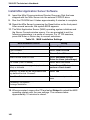
Controller Alarm Port Pinouts .....................................................................................253
Controller Remote Alarm Behavior .............................................................................253
Network Services Units .....................................................................................................254
Universal/R2 NSU .......................................................................................................254
BRI NSU .....................................................................................................................258
Analog Services Unit .........................................................................................................260
5485 IP Paging Unit ..........................................................................................................266
SX-200 Bay .......................................................................................................................267
Appendix B : Installation Planner
Reserved IP Addresses ..............................................................................................271
MXe Server/MXe/AX/CXi/CXi II Requirements for IP Networking ..............................272
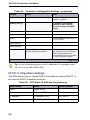
Controller Configuration Settings (RTC) .....................................................................275
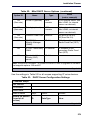
DHCP Configuration Settings .....................................................................................276
Programming E2T via Debug Cable or Secure Telnet ...............................................282
Configuring External DHCP Settings for E2T .............................................................283
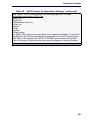
Configuring a Windows 2000 or Windows 2003 DHCP Server (Rel 7.0 and later) ....284
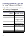
System Administration Tool Settings ..........................................................................286
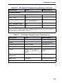
IP Phone Settings .......................................................................................................286
Telephone Programming Guide ..................................................................................286
Increasing DSP Resources .........................................................................................287
Appendix C : Typical Network Configurations
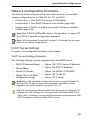
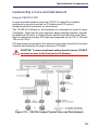
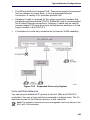
Network Configuration Examples ......................................................................................301
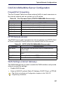
DHCP Server Settings ................................................................................................301
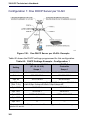
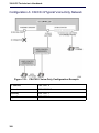
Configuration 1: One DHCP Server per VLAN ...........................................................302
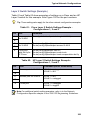
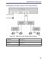
Configuration 2: One DHCP Server for Two VLANs ...................................................304
Configuration 3: Router on a Stick ..............................................................................305
LLDP-MED and IP Phone Network Policy ..................................................................305
Cisco Discovery Protocol (CDP) .......................................................................................306
CXi/CXi II/MXe/MXe Server Configuration ........................................................................307
Firewall/Port Forwarding .............................................................................................307
PPTP Remote Access ................................................................................................307
WAN Settings (Internet Gateway) ...............................................................................307
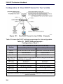
Configuration A: CXi/CXi II/Typical Voice-Only Network ............................................308
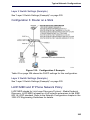
Configuration B: MXe Typical Voice-Only Network ....................................................309
Configuration C: CXi/CXi II Typical Voice and Data Network .....................................310
Configuration D: MXe Typical Voice and Data Network .............................................311
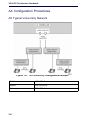
AX Configuration Procedures ............................................................................................312
AX Typical Voice-Only Network ..................................................................................312
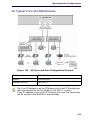
AX Typical Voice and Data Network ...........................................................................313
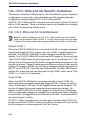
CXi, CXi II, MXe and AX-Specific Guidelines ....................................................................314
CXi, CXi II, MXe and AX VLAN Behavior ...................................................................314
vii
Enter document Title using Variable
Implementing a Voice-Only Network .......................................................................... 317
Implementing a Voice and Data Network ................................................................... 319
Installing External Layer 2 Switches .......................................................................... 322
Windows 2000 FTP Server .............................................................................................. 326
Appendix D : Status LEDs
Controller LEDs ................................................................................................................ 332
Controller Alarm LEDs (AX, MXe/MXe Server) .......................................................... 336
Controller Power LED (AX, MXe/MXe Server, CX/CXi, CX II/CXi II) ......................... 336
Hard Drive or Flash Activity ....................................................................................... 336
RAID Controller .......................................................................................................... 337
FIM ............................................................................................................................. 340
LAN Ethernet Ports .................................................................................................... 341
CIM, Embedded and Quad MMC ............................................................................... 342
Controller Alarm ......................................................................................................... 342
Power Supply Unit LEDs ............................................................................................ 345
Dual T1/E1 Framer Module ........................................................................................ 345
T1/E1 Combo Card .................................................................................................... 346
Quad BRI Framer Module .......................................................................................... 347
Network Services Unit LEDs ............................................................................................ 349
Universal/R2 NSU ...................................................................................................... 349
BRI NSU .................................................................................................................... 352
Analog Services Unit LEDs .............................................................................................. 354
ASU II Card LEDs ............................................................................................................ 356
ASU II ONS and Combo Card Alarm LED ................................................................. 356
ASU II ONS Card Activity LED ................................................................................... 356
ASU II Combo Card Activity LED ............................................................................... 356
IP Device LEDs ................................................................................................................ 357
Peripheral Cabinet LEDs .................................................................................................. 358
SX-200 Bay LEDs ............................................................................................................ 360
Digital Services Unit LEDs ............................................................................................... 363
In-Line Power Unit LEDs .................................................................................................. 366
Appendix E : FRU Part Numbers
Hardware Part Numbers ............................................................................................ 371
Software Part Numbers .............................................................................................. 378
Appendix F : System Capacity and Parameters
System Parameters .......................................................................................................... 383
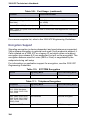
Port Usage ................................................................................................................. 383
Encryption Support .................................................................................................... 384
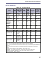
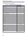
IP Set Features .......................................................................................................... 385
IP Phone Power Consumption ................................................................................... 386
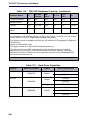
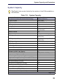
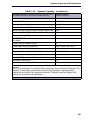
Capacity ........................................................................................................................... 387
Hardware Capacity .................................................................................................... 387
System Capacity ........................................................................................................ 389
viii
Table of Contents
Appendix G : Older Hardware and Software
Procedures for Older Controllers ......................................................................................395
Programming the Controller DHCP Server Settings (prior to Rel 7.0) ........................395
To use an alternative DHCP server (prior to Rel 7.0) .................................................396
Configuring a Windows 2000 DHCP Server (prior to Release 7.0) ............................397
Program DHCP for VLAN (prior to Rel 7.0): ...............................................................399
Connect a Windows 95/98 PC to the NSU via Dial-Up ...............................................401
Physically Connecting the PC to an NSU ...................................................................402
Creating a Dial-Up Network Connection on Windows 95/98 ......................................402
Migrate SX-2000 PBX Hardware ................................................................................404
Collecting System Logs Manually ...............................................................................405
Collecting System Lockup Logs Manually ..................................................................406
Peripheral Cabinet ......................................................................................................407
Digital Service Unit (DSU) ..........................................................................................407
Index .................................................................................................................................409
ix
Enter document Title using Variable
x
Chapter 1
Getting Started
3300 ICP Technician’s Handbook
2
Getting Started
Purpose of This Handbook
This handbook provides certified 3300 ICP technicians with instructions to
install, upgrade, maintain and troubleshoot the Mitel® 3300 IP
Communications Platform (ICP). For information on programming, please
refer to the System Administration Tool Help system.
Documentation for Unsupported Controllers
This document covers controllers supported by MCD Release 4.0 and
higher. For controllers, such as MX, 100-, 250-, and 700-user controllers,
that are not covered here, refer to earlier versions of the Technician’s
Handbook.
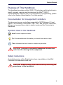
Symbols Used in the Handbook
Note:Provides important details.
Tip: Provides additional information you should know about a topic.
Time: Indicates the time it takes to complete a procedure.
CAUTION: Indicates a potentially hazardous situation that
could result in damage to the equipment.
Safety Instructions
A printable version of the Safety Instructions is available on the Mitel
Customer Documentation web site.
CAUTION: Read the safety instructions before performing the
procedures in this handbook.
3
3300 ICP Technician’s Handbook
CAUTION: Failure to follow all instructions may result in
improper equipment operation and/or risk of electrical shock.
Refer to “3300 Safety Instructions” for complete safety information.
CAUTION: To prevent ESD damage to the equipment: (1)
Ensure that the system is grounded before you install a card.
(2) Whenever you handle cards, wear an anti-static strap
(attached to the cabinet). (3) When removing cards from the
cabinet, immediately place them in an anti-static bag.
CAUTION: All installation, field replacement, and servicing
procedures must be carried out by service personnel who
have successfully completed the Mitel Installation and maintenance training course.
CAUTION: Hardware is sensitive to shock and vibration; handle hardware with care.
CAUTION: Provide a permanent ground for all controllers and
units through the ground connection on each cabinet.
CAUTION: BRI Interface is not available in Taiwan. Use of this
interface is prohibited.
CAUTION: When sold in Taiwan, the MXe Controller supports
ISDN T1/E1 and Leased Line T1. However, it does not support
Leased Line E1 and ISDN BRI in Taiwan.
Note: The ground symbol within a circle identifies the terminal to be
connected to an external protective conductor. Connect this terminal to
earth ground before you make any other connections to the equipment.
4
Getting Started
Start Here Guide
What You Received
3300 ICP Controller
•
Set of feet and rack mounting hardware
Hardware Components
•
System i-Button (except in MXe Server)
•
Hard drive (ordered separately for MXe, CX, CXi, CX II and CXi II)
or Compact Flash Card (AX only)
Software
•
MXe, CX, CX i CX II and CXi II: provided on separately ordered
hard drive; see Appendix E on page 369 for part numbers.
•
AX and MXe Server: Mitel Communications Director Installation CD
(included with controller)
Optional Hardware, such as
•
RAID Hardware and hard drives (2)
•
Redundant Power Supply
•
NSU, ASU
What You Need for Installation
Phillips screwdrivers
Anti-static strap
CAT 5 or better cable with RJ-45 connector
Computer for programming the 3300 ICP
IP addresses for the controller, E2T, and IP telephones
List of purchased options and password
IMAT (not required for embedded PRI)
Preparation
Review your purchase order
Complete Appendix B: “Installation Planner” on page 269
5
3300 ICP Technician’s Handbook
Review Appendix C: “Typical Network Configurations” on page 299
Initial Setup
“Connect PC to Controller” on page 13
“Establish Communication with Controller” on page 25
“Enable Licenses and Options” on page 29
Install Hardware
“Determine Controller Module Configuration” on page 41
“Identify Controller Component Options” on page 45
“Remove Controller Cover” on page 47
“Install Controller Modules” on page 48
“Install Controller Stratum 3 Clock Module” on page 51
“Install Controller Hardware” on page 51
“Rack Mount the Controller” on page 51
“Install Service Units and Cabinets” on page 58
“Install Telephones” on page 64
“Install and Configure Music on Hold” on page 65
“Register IP Devices from the Telephone” on page 67
Program System
“Log into the Programming Tools” on page 71
“Configure NSU via IMAT” on page 73
“Program the Controller DHCP Server (MXe, CX/CXi, CX II/CXi II)” on
page 76
“Program LS Trunk Settings via LS Measure Tool” on page 78
“Configure Analog Music On Hold/Paging” on page 79
Install System Software
Install the System Software:
-
6
“Install System Software Manually” on page 85
Getting Started
-
“Install System Software using the Software Installer” on page 91
Upgrade system software:
-
“Online Upgrade” on page 94
-
“Offline Upgrade” on page 98
“Installing MSL Software on APC (CX/CXi) or APC-CX(i) II (CX II/CXi
II)” on page 105
Maintain System
“Back Up a Database” on page 130
“Migrate SX-2000 Database Across Platforms” on page 136
“Export Configuration Data” on page 139
“Import Configuration Data” on page 140
“Assign Static IP Addresses to IP Phones” on page 142
“View Logs” on page 119
“Detecting Device Moves” on page 126
“Load IP Phone Software Remotely” on page 112
“Assign Static IP Addresses to IP Phones” on page 142
“Perform a System Reset” on page 129
“Restore a Database” on page 132
“Recover MXe Server” on page 146
Install and Replace Units
“Component Replacement Notes” on page 159
“Add or Replace Controller FRUs” on page 166
“Add or Replace Controller FRUs” on page 166
7
3300 ICP Technician’s Handbook
About the 3300 ICP
The 3300 ICP is a Voice over IP solution that delivers robust call control,
extensive features and supports a wide range of desktop devices and
applications for medium-to-large enterprises. There are several system
configurations:
•
the CX and CX II with embedded analog
•
the CXi and CXi II with embedded analog and embedded Layer 2
switch for sites with 8-100 lines (150 on CXi II);
•
the MXe base with embedded analog supports 300 users before
expansion;
•
the expanded MXe supports 1400 users;
•
the AX controller delivers an increased density of analog devices;
•
the MXe Server provides capacity for up to 5000 simultaneous users.
3300 ICP Documentation - Mitel eDocs
For customer documentation, including Knowledge Base Articles, on all
Mitel products go to the Mitel Edocs web site at http://edocs.mitel.com.
Tip: You must have a Mitel OnLine (MOL) account to access technical
documentation on Mitel Edocs. Access to end-user documents, such as
telephone user guides, does not require an MOL account.
Access Your Mitel Options Password
You must obtain your Mitel Options Password through Mitel OnLine
(www.mitel.com). You will create your application record on the AMC via
Mitel Online (see “Enable Licenses and Options” on page 29). This
password is required during a software upgrade or installation procedure.
A new password has been issued to you if you are purchasing new options.
Mitel recommends using online synchronization with the AMC to update
your password. Using online synchronization will allow you to license your
controller software and options immediately. Remember to print a record
of your options for future reference.
If you do not have internet access where your controller is located:
Connect to AMC at Mitel Online and choose the manual licensing option.
When you print your options page, it will include your password and
Applications Record ID (ARID). Use this password when installing the
options on your controller.
8
Getting Started
To upgrade software, confirm a current password, or purchase new options
and receive a new password, use the AMC at Mitel Online any time.
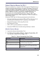
Contacting Mitel
Order Desk
You can reach the Order Desk at 1-800-796-4835.
Repair Services Department
You must get a Return of Merchandise Authorization (RMA) form from the
Repair Services Department before sending equipment back to Mitel.
If you are in North America, you can reach the Repair Services Department
at 1-888-222-6483.
If you are in any other region, contact your local regional support service.
Technical Support
Please contact Mitel Technical Support if you require technical assistance.
If you cannot resolve the problem by using the 3300 ICP Troubleshooting
Guide, please collect the required information listed in the applicable
section(s) of the 3300 ICP Troubleshooting Guide before calling Mitel
Technical Support.
If you are in North America, you can reach Technical Support at
1-800-561-0860 or 1-613-592-2122.
If you are in any other region, contact your local regional support service.
For regional contact information, follow the “Contact Us” link at Mitel.com.
9
3300 ICP Technician’s Handbook
10
Chapter 2
Initial Setup
3300 ICP Technician’s Handbook
12
Initial Setup
Connect PC to Controller
To configure the system, you must connect a PC to the controller.
PC Requirements
You need a Windows-based computer to program, maintain and
troubleshoot the 3300 ICP, and to install/upgrade the MCD software.
Computer Recommendations
•
Windows® NT 4.0, Windows 2000, Windows XP, or Windows Vista
Business or Ultimate.
Computer Requirements
•
Windows 98, Windows NT 4.0, Windows 2000, Windows XP, or
Windows Vista.
•
Network interface card (NIC)
•
1 GB free disk space (minimum)
•
Internet Explorer 6.0, 7.0 or 8.0 with the latest Service Pack and
128-bit encryption. (IE 7.0 or 8.0 can be used with Rel 7.1 UR2 and
later.)
•
JRE (Java Run-time Environment) 1.6.0_1 or later installed
•
VT100™ emulator program
•
FTP Server (can be installed with Microsoft® IIS or PWS, for example)
Tip: Windows 98 with PWS does NOT include an FTP server application
required for installations of 3300 ICP Software before Rel 8.0, and will not
work for the software installation/upgrade process unless a third-party server
application is used. If you are upgrading Rel 8.0+ software on a Rel 8.0 or
8.0+ system, you don’t need an external FTP server.
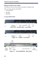
AX, MXe, CX, CXi, CX II and CXi II Controller
1. Connect an RS-232 straight DTE male to female serial cable between
the controller’s Maintenance port and the PC’s serial port (cable not
provided).
2. Program the PC’s serial port (from the communication program) with
the following settings:
-
Baud Rate: 9600
Data Bits: 8
Parity: None
- Stop Bits: 1
- Flow Control: None
13
3300 ICP Technician’s Handbook
3. Connect a straight-through Ethernet cable (RJ-45) from the controller
leftmost Ethernet port (port 17 on the CXi and CXi II; port 1 on the CX,
CX II, MXe, and MXe Server) and the PC’s network interface card
(NIC). When connecting to the AX, either Ethernet port will work.
4. Program the PC’s NIC with the following settings:
-
IP Address: 192.168.1.n (where n is a value between 30 and 254)
-
Subnet Mask: 255.255.255.0
Note:For the MXe Server, the controller IP is the System IP address; default
192.168.1.5. Reserve 8 consecutive IP addresses for the MXe Server.
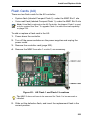
Power Up the Controller
1. Connect the female end of the power cable to the controller, and
secure it with the latch (if provided).
2. Connect the other end of the power cable to a protected outlet. Turn
on power switch (MXe, MXe Server, CX/CXi, and CX II/CXi II). If there
are two power supplies, ensure that both power switches are turned
on. The controller starts up.
Time: The controller can take up to 15 minutes to start-up.
3. Proceed to “Establish Communication with Controller” on page 25
MXe Server
Unlike the other 3300 ICP controllers, the MXe Server arrives complete,
with all of the software pre-installed on the hard disk. This includes the
Mitel Communications Director (MCD) software and the VxWorks virtual
machine. There is still some configuration and licensing work to do before
the MXe Server can be used in your network, though, and the instructions
are provided in this section.
The MXe Server is shipped with an Application Processor Card
(APC-MXe) that runs the MCD call control software. Also included
standard on the MXe Server are the RTC and the E2T cards. All of these
processors must be able to communicate with each other, so IP addresses
must be assigned to all of them.
14
Initial Setup
Tip: If you are replacing an existing 3300 ICP controller with an MXe Server
and you want to use the same system IP address for the MXe Server, initially
you will only be able to connect to the MXe Server from the local subnet.
Before you can connect to the MXe Server from other subnets, you must
manually clear the router ARP cache or wait until the router ARP cache is
automatically updated. Refer to the latest 3300 ICP Release Notes for
instructions.
Tip: The MXe Server is shipped with two hard drives, one with the software
loaded and one blank. Before continuing, mirror the blank drive starting at
Step 11 of the procedure described in “Replace One Hard Drive in an MXe
II/MXe Server” on page 210.
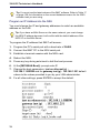
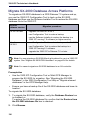
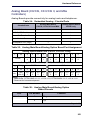
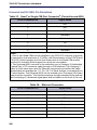
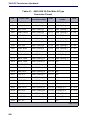
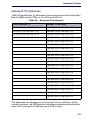
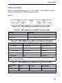
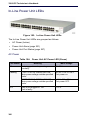
The MXe Server is shipped with default IP addresses assigned. The
defaults are shown in Table 1.
Table 1: Default IP Addresses for the MXe Server
ESM Name
Default IP Address/ Subnet Mask
Virtual subnet
192.168.1.4/30
System IP Address
192.168.1.5/30
Reserved IP Address
192.168.1.6/30
Virtual broadcast
192.168.1.7/30
APC IP Address
192.168.1.8/24
Media Gateway IP Address
192.168.1.2/24
E2T Card IP Address
192.168.1.3/24
Layer 2 (L2) Switch IP Address
192.168.1.1/24
Before You Begin
To complete this procedure, you will require
Laptop
Communications application (for example, Hyperterminal)
RS-232 serial cable
Ethernet cable (straight-through)
MCD Software Installer tool
Application Record Identification Number (AMC ARID)
15
3300 ICP Technician’s Handbook
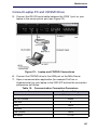
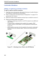
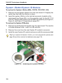
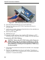
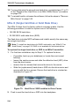
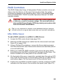
Connect Laptop PC
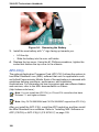
1. Power up the MXe Server and wait approximately 3 minutes for the
software to enable the printer port.
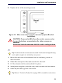
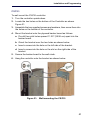
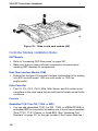
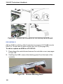
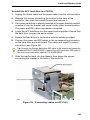
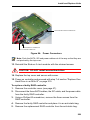
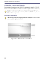
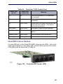
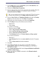
2. Connect the RS-232 serial cable between the COM 1 port on your
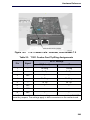
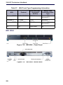
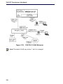
laptop to the server printer port (see Figure 1).
Figure 1: Laptop Connections
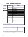
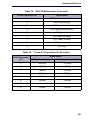
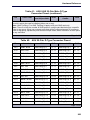
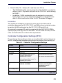
3. Open a communication application (for example ProCom or
Hyperterminal) on your laptop to the 3300 ICP and set the connection
parameters as follows:
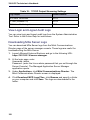
Table 2: Communication Connection Parameters
Parameter
Port
Bits Per Second
Data Bits
Parity
Stop Bits
Required Setting
COM 1 (example only)
38400
8
None
1
Flow Control
None
Emulation
VT100
16
Initial Setup
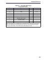
Configure MAS Parameters
4. After the Server Console screen appears, you are prompted to accept
the End-User License Agreement. Select Accept.
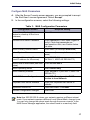
5. In the configuration screens, select the following settings:
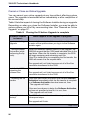
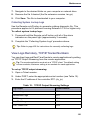
Table 3: MAS Configuration Parameters
Configuration Screen
Required Setting
Restore from Backup (this screen
relates to a backup of the Linux
database)
Select No.
Choose Linux Admin Password
Enter a password. Then, enter it again to
verify it. Note that passwords are
case-sensitive. Also, see Caution below
this table.
Select Primary Domain Name
Enter name (for example mitel.com)
Select System Name
Enter name (for example the company
name)
Enter Local Networking Parameters Enter 192.168.1.8
(local IP address for this server)
(INITIALLY, KEEP AS DEFAULT!!!)
Select Local Subnet Mask (see Note Enter 255.255.255.0
below)
Select Operating Mode
Select Server-only
Select Gateway Address
Enter 192.168.1.1 (INITIALLY, KEEP AS
DEFAULT!!!)
Set DHCP Server Configuration
Select Off - Do not provide DHCP
Service to local Network
Corporate DNS Server Address
Enter your corporate DNS server IP
address.
Application Record ID
Leave field blank. Click Next.
Activate Configuration changes
Select Yes
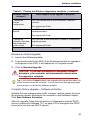
Note:Use 255.255.255.0 unless your network requires a different subnet
mask. If your network requires a different Local Subnet Mask, change it now.
You can only change the subnet mask through the server console. In the
MAS Server Manager application, the subnet mask is a read-only field.
17
3300 ICP Technician’s Handbook
CAUTION: Ensure that you record your Linux Admin password. If you lose this password, it cannot be recovered. You
will have to re-install the MAS software and set a new password.
Configure Server Manager Fields
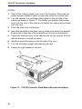
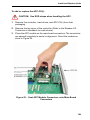
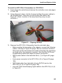
6. Connect the ethernet cable from the Network Interface Card (NIC)
connector on your laptop to Port 1 of the MXe Server.
7. On your laptop set the NIC IP address to 192.168.1.20. The following
steps are for Windows 2000 or Windows XP operating systems:
-
Click Start, click Settings, click Network and Dialup
Connections, and then click Local Area Network Connection
-
Select Internet Protocol (TCP/IP)
-
Click Properties
-
Select Use the following IP address
-
Enter the following IP address: 192.168.1.20
-
Enter Subnet Mask (use the same Subnet Mask that you
configured for the APC)
-
Click OK
-
Click Start, click Settings, click Network and Dialup
Connections, and then click Local Area Network Connection.
Ensure that the connection is Enabled.
8. Launch Microsoft Internet Explorer and go to the following URL:
https:/192.168.1.8/server-manager.
9. At the login page, enter
Username: admin
Password: (enter the Linux admin password that you set through the
Server Console). The Managed Application Server Manager
application opens.
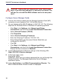
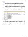
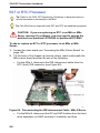
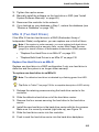
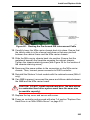
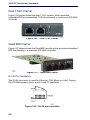
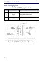
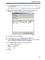
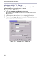
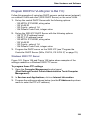
10. Under Applications, click Mitel Communications Director. The
Mitel Communications Director screen is displayed:
18
Initial Setup
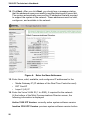
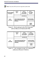
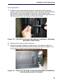
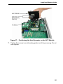
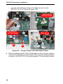
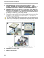
Figure 2: Example of Mitel Communications Director Screen
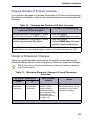
11. Click Modify to change the existing System IP Address and the APC
Gateway Address.
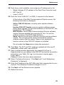
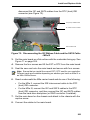
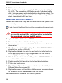
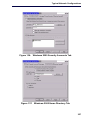
12. Enter the new System IP Address and APC Gateway Address.
13. The IP addresses in the following screens are examples only.
Figure 3: Change the System IP and APC Gateway Addresses
19
3300 ICP Technician’s Handbook
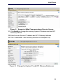
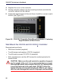
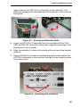
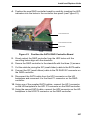
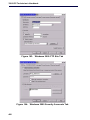
14. Click Next. After you click Next, you should see a message stating
that the addresses were successfully modified displayed in green text.
The system automatically reserves four IP addresses that are required
to support the system in the network. These addresses must be valid,
contiguous, and available in the network.
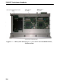
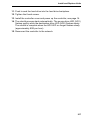
.
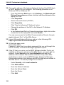
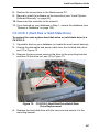
Figure 4: Enter the New Addresses
15. Enter three, valid, available, and contiguous IP addresses for the
-
Media Gateway IP (IP address of the Real Time Controller card)
-
E2T Card IP
-
Layer 2 (L2) IP
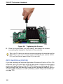
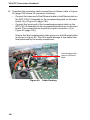
16. Enter the Voice VLAN ID (1 to 4093), if required for the network.
At the bottom of the Mitel Communications Director screen, the
following information is displayed:
Active 3300 ICP Version: currently active system software version
Inactive 3300 ICP Version: previous system software version before
20
Initial Setup
latest upgrade. On an initial installation of the 3300 ICP, this field
displays "Not Installed".
MCD Version: current Mitel Communications Director software
version that was installed using the Software Installer tool. It is NOT
the software version of the MCD blade software.
Swap: reboots the call server with the currently inactive software
version. The currently active version becomes the inactive software
version after the reboot. Swap is only displayed if an Inactive version
of the 3300 ICP software is installed.
Do not enable the Swap option during this procedure.
17. Click Save. The E2T and RTC cards are updated with the new IP
addresses, subnet mask, and VLAN ID.
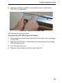
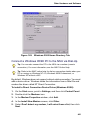
18. Open a communication application (for example ProCom or
Hyperterminal) on your laptop to the 3300 ICP and set the connection
parameters (see Table 2). Log in to the server console again.
Login: admin
Password: (enter the Linux admin password)
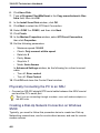
19. Select “Configure this server”. Press the Tab keyboard key until “Local
Networking Parameter” is displayed.
20. Enter the IP address of the APC-MXe card that is appropriate for your
network. The Gateway IP address changes to x.x.x.1.
21. Press the Tab keyboard key until the Reboot screen appears.
22. Reboot the server.
23. Change the address of the laptop’s Network Interface Card (NIC) back
to the IP address for your network. The following procedure is for
Windows 2000 or Windows XP:
-
From the Windows Start menu, click Settings, click Network and
Dial-up Connections, and then click the Local Area Network of the
laptop NIC card.
-
Click Properties.
-
Select Internet Protocol (TCP/IP).
-
Click Properties.
-
Click “Use the following IP Address” option.
-
Change the address of the NIC to the Network IP Address.
21
3300 ICP Technician’s Handbook
-
Click OK.
-
In the Network and Dial-up Connections window, right-click on the
connection for the laptop NIC and click Enable.
You can now connect to the Mitel Communications Director through
gigabit ethernet Port 1 of the MXe Server.
24. Launch Microsoft Internet Explorer and go to the following URL:
https:/<your APC IP>/server-manager.
25. At the login page, enter
Username: admin
Password: (enter the Linux admin password that you set through the
server console). The Server Manager application opens.
26. If the PC that you use to run the MCD Software Installer is not installed
on the same network as the MXe Server, you must add the network.
Under Security, click Local Networks and add the IP address of the
network. Also add the networks of any other Mitel applications or tools,
such as OPS Manager, Enterprise Manager, system administrator
client stations and so forth that require access to the MXe Server. To
extend privileges to a network:
- Under Security, click Local networks.
- Click Add network.
- Enter the Network Address.
- Enter the Subnet Mask.
- Enter the Router.
- Click Add.
27. If the system is connected to the internet, the date and time is set
automatically from a Network Time Server. Optionally, you can set the
date and time manually:
- Under Configuration, click Date and Time.
- Click Disable Network Time Server.
- Click Save.
- Set the date, time, and time zone.
- Click Save.
28. From the Software Installer, connect to the MXe Server.
29. Re-license the 3300 ICP software on the MXe Server. See “Licensing
the MXe Server with AMC” on page 23 for instructions.
22
Initial Setup
30. Launch the 3300 ICP System Administration Tool and enter the
following maintenance command:
-
UpgradeBootrom ALL
31. Launch the Group Administration tool and set the system date and time.
Licensing the MXe Server with AMC
1. Change the IP address of your PC back to its address on your network.
2. Re-connect your PC NIC to your corporate network.
3. Connect the MXe-Server's Gig LAN Port 1 to your corporate network.
4. Install and run MCD Software Installer (release 8.0 or later).
5. Click on the MXe Server radio button.
6. Type in:
- APC IP address: <APC IP address>
- Login = root
- Password = <your current MSL password>
- MN 3300 Login = system
- Password = password
The 3300 ICP Address is blank and you won’t be able to edit it.
7. Click Configure.
Time: It may take a few minutes for the next screen to appear.
8. In the screen that appears, click on License Atlas. Click Next.
9. Click License and Option Configuration. Click Next.
10. On the Licensing screen, type your ARID and click Retrieve
Licenses.
11. When the Options fields have been automatically filled in, click Next.
12. When the next screen appears, click Start.
23
3300 ICP Technician’s Handbook
Setting your DNS Server IP
1. Log in to the MXe-Server System Administration Tool (for example
10.x.y.25).
2. Navigate to the System IP Properties form.
3. On the lower panel, enter your corporate DNS Server IP address in the
DNS Server IP address field.
4. Click Save.
Note:All of the IP addresses will be read-only in the System Administration
Tool.
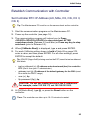
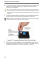
Verify the Connections
Perform the steps below to verify the connections between the
Maintenance PC and the controller.
1. To verify the serial connection in the VT100 emulator, press ENTER.
-
If the serial connection is installed and programmed properly, a
right-pointing arrow () is displayed when you press ENTER.
2. To verify the Ethernet connection from the PC:
24
-
For the MXE Server: PING the controller System IP address
(default is 192.168.1.5).
-
For all other controllers: PING the controller RTC IP address
(default is 192.168.1.2).
-
If the connection is installed and programmed correctly, the
controller replies to the PING.
Initial Setup
Establish Communication with Controller
Set Controller RTC IP Address (AX, MXe, CX, CXi, CX II,
CXi II)
Tip: The Maintenance PC must be on the same subnet as the controller.
1. Start the communication program on the Maintenance PC.
2. Power up the controller (see page 14).
3. The communication program will instruct you to Press
<SPACE><SPACE><SPACE> to stop auto-boot AFTER
countdown starts (Release 5.2 and later) or Press any key to stop
auto-boot (prior to Release 5.2).
4. When [VxWorks Boot]: is displayed, type c and press ENTER.
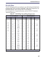
5. For each VxWorks setting shown in bold inTable 49 on page 275,
enter a value, and then press ENTER. For all other settings, press
ENTER to accept the default:
Tip: If DHCP (flags=0x40) is being used on the E2T, leave the inet on ethernet
field blank.
-
inet on ethernet (e), IP address and subnet mask (hex) for controller
RTC (Get it from your IT administrator.)
-
gateway inet (g), IP address of the default gateway for the 3300 (must
be outside the DHCP range)
-
user (u), ftp
-
ftp password (ftp)), ftp.
CAUTION: Do not use leading zeroes in the IP addresses.
For example, enter 192.168.1.2; not 192.168.001.002.
6. At [VXWorks Boot], type @, or press the Reset button on the
controller.
Time: The controller can take up to 10–15 minutes to restart.
25
3300 ICP Technician’s Handbook
Configure System IP Address (MXe Server)
To replace the default System IP address with a new IP address:
Tip: All of the MXe Server IP addresses must be on the same subnet.
1. Launch the MSL server console, and select Configure this Server.
2. Set the APC IP address to 192.168.1.8.
Note:You must temporarily set the APC IP address to the default setting
to be able to configure system IP addresses. Once you are done
configuring these IP addresses, you will reset the IP address on the APC.
3. Disconnect the MXe Server from the network.
4. Configure a local PC with a static IP address on subnet 192.168.1.0/24
and connect it to the MXe Server. See Table 1 on page 15 for the list
of addresses that will be used by the MXe Server.
5. Launch the web-based MSL Server-Manager, and select the Mitel
Communications Director blade panel. The APC IP address will be
read-only. This panel now allows you to configure system IP
addresses, RTC, E2T, L2 IP, and Gateway IP. These IP addresses
must be on the customer subnet. When you are finished configuring
the IP addresses, click Save.
6. In the MSL server console menu, select Configure this Server, and
reset the APC IP address to the customer subnet (same subnet as the
above IP addresses).
7. Click Activate Changes (this will cause a system reset).
Configure the Layer 2 Switch (AX, MXe, CXi, CXi II)
The internal Layer 2 switch in the CXi, CXi II, and MXe must be
programmed with an IP address in the same subnet as the RTC IP
address, or the switch will not operate properly.
To set the Layer 2 switch IP address, complete the System IP Properties
form, and then reboot the system.
Note:The 16 10/100 Mbps ports are disabled on the CXi and CXi II during
bootup, as is the right-hand side (when viewed from the front) Gigabit port
on the CX, CX II and MXe.
26
Initial Setup
Tip: Refer to the System Administration Tool Online Help for detailed
instructions on programming the IP Network Configuration forms associated
with the CXi, CXi II, MXe, and MXe Server.
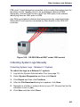
1. Connect an Ethernet cable between the Layer 2 switch on your
network and one of the following ports:
-
leftmost available Ethernet (port 17) on the CXi and CXi II controller
using a straight-through cable
-
the left Gigabit port on the CX, CX II, and MXe controller using a
straight-through cable
-
either of the Ethernet ports on the AX controller using a cross-over
cable.
2. Program the Layer 2 switch with the appropriate settings (see
“Network Configuration Examples” on page 301 for more information).
Tip: Typically, in a VLAN environment, an access port is used to connect the
Layer 2 switch to the controller, and trunk ports to connect the Layer 2 switch
to the IP Phones.
Tip: IP trunks cannot work through the WAN port.
3. See your IT administrator for information to set up and program a
DHCP server. We recommend that you use the controller’s internal
DHCP server to provide a static IP address to the E2T.
4. If you are not using the controller’s DHCP server, disable it in the
DHCP Server form.
Tip: See “Configuring a Windows 2000 DHCP Server (prior to Release 7.0)”
on page 397 for information on programming 3300 ICP DHCP settings on a
Windows 2000 DHCP server.
Configure the Layer 2 Switch (MXe Server)
The MXe Server starts with a default IP address for the internal Layer 2
switch, and all of the MXe Server IP addresses must be changed (at the
same time) to sit on the same subnet as the L2 switch address.
Note:The Gigabit port on the MXe Server located on the right-hand side of
the controller front panel is disabled during bootup.
27
3300 ICP Technician’s Handbook
Tip: Refer to the preceding initial setup procedures for detailed instructions
on how to reset the system defaults and then reprogram new system IP
addresses.
When you configure the Layer 2 Switch, ensure that you do the following:
1. Connect an Ethernet cable between the Layer 2 switch on your
network and left Gigabit port on the MXe Server.
2. Program the Layer 2 switch with the appropriate settings (see
“Network Configuration Examples” on page 301 for more information).
Tip: Typically, in a VLAN environment, an access port is used to connect the
Layer 2 switch to the controller, and trunk ports to connect the Layer 2 switch
to the IP Phones.
Tip: IP trunks cannot work through the WAN port.
3. See your IT administrator for information to set up and program a
DHCP server.The MXe Server doesn’t have an internal DHCP server, so you
must use an external DHCP server.
Tip: See “Configuring a Windows 2000 DHCP Server (prior to Release 7.0)”
on page 397 for information on programming 3300 ICP DHCP settings on a
Windows 2000 DHCP server.
28
Initial Setup
Enable Licenses and Options
The online licensing process, managed by the Mitel Application
Management Centre (AMC) allows Solution Providers who have accounts
on the AMC to manage software licenses online. Each company is able to
supply customers instantly if new licenses or options are required.
To enable or upgrade licenses and options, you must connect to the AMC
using either the MCD Software Installer Tool or the 3300 ICP System
Administration Tool. Connecting to the AMC Server requires specific
settings for the Software Installer Tool and the System Administration
Tool. Refer to "MCD Software Installer Tool Requirements for AMC" on
page 30 and "3300 ICP System Requirements for AMC" on page 30.
If you want to be able to transfer licenses and options between controllers,
you must use the AMC to create an Application Group containing
controllers with a System Type of “Enterprise” and license sharing
enabled. Then, when you enable the licenses and options on the
controllers, designate one controller as the Designated License Manager
(DLM) for the Application Group. This enables you to deallocate licenses
from one group member and allocate them to another, individual system
limits permitting.
After completing changes to an account on the AMC, you can perform an
automatic sync (recommended) with the AMC, which requires only that
you enter the Application Record ID for each individual controller and, if
license sharing is enabled, the Group Application record ID on the DLM. .
To enable licenses and options on the controller, you only need to
complete one of the following procedures:
Tip: It is recommended that you perform an automatic sync.
•
“Automatic Sync with AMC via MCD Software Installer Tool (Rel 6.0 or
later)” on page 31.
•
“Automatic Sync via System Administration Tool” on page 33.
•
“Manual License and Options Entry via MCD Software Installer Tool”
on page 34.
•
“Manual License and Options Entry via System Administration Tool”
on page 35.
29
3300 ICP Technician’s Handbook
MCD Software Installer Tool Requirements for AMC
The PC that is running the Software Installer has the following network
requirements:
1. DNS Name Resolution: Because the SI win32sync client performs a
name lookup on “register.mitel-amc.com”, the SI host PC needs to be
properly configured for DNS name resolution.
2. TCP/IP Source Port on the SI Host: A Windows operating system will
use an arbitrary high port for the TCP connection to the AMC. If the SI
PC is behind a firewall, the firewall must allow connections from high
ports (greater than 1024).
3. TCP/IP Destination Port on the AMC: The SI win32sync client will
attempt to establish a connection to register.mitel-amc.com TCP port
22. After 5 seconds, if the connection is not established, the client will
try port 8222. If there is still no success, the third attempt is with port
80 using the HTTP/1.1 protocol CONNECT method.
If the SI PC is behind a firewall, the firewall must allow connection to
at least one of port 22, port 8222, or port 8.
4. SI Host PC behind an HTTP Proxy Server: If the HTTP/1.1
CONNECT method is used and the SI PC is configured to use an
HTTP proxy server, then the CONNECT request will be through the
proxy server. This is the same method used by web browsers to
establish HTTPS connections through proxy servers. If the SI host PC
can reach https://www.mitel-amc.com from a web browser, then it
should also be able to establish a win32sync connection by using the
HTTP/1.1 CONNECT method. If there is a problem reaching
https://www.mitel-amc.com from a browser on the SI host PC, then the
firewall and/or proxy server on the customer premise may need to be
reconfigured to allow HTTP/1.1 CONNECT requests.
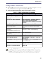
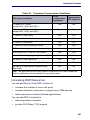
3300 ICP System Requirements for AMC
1. DNS Name Resolution: Because the MiSync client performs a name
lookup on “register.mitel-amc.com” and “sync.mitel-amc.com”, the ICP
needs to be properly configured for DNS name resolution using the
System IP Properties form in the System Administration Tool.
2. TCP/IP Source Port on the ICP: The MiSync client will connect to
TCP port 443 (https) on the AMC. If the ICP is behind a firewall, the
firewall must allow TCP connections from the ICP to TCP port 443 on
the AMC.
30
Initial Setup
3. ICP behind an HTTP Proxy Server: The MiSync client uses HTTPS
to communicate with the AMC. The HTTP/1.1 CONNECT method is
the standard used by proxy servers to proxy HTTPS. There should be
no extra configuration work required. See Step 4, “SI Host PC behind
an HTTP Proxy Server” on page 30.
4. CXi, CXi II, MXe-Specific WAN Considerations: Program the
Internet Gateway (WAN interface) IP address details (see "MXe
Server/MXe/AX/CXi/CXi II Requirements for IP Networking" on
page 272).
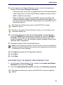
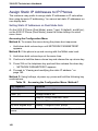
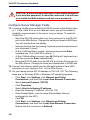
Automatic Sync with AMC via MCD Software Installer
Tool (Rel 6.0 or later)
1. Launch the Software Installer and select either the MXe Server check
box or the 3300 ICP check box to get to the Login Dialog.
2. Enter the Iogin information and the IP addresses. Click Configure.
Tip: If the SI is connecting to the MXe from behind a firewall, the firewall must
be configured to allow https (443), ftp (20, 21), and ssh (22).
Note that a DNS server is required.
3. Perform one of the following:
-
If the software load you need is a higher release than the software
that is pre-loaded on the MXe Server’s hard drive, or if you are
installing software on a 3300 ICP, click Perform Upgrade.
-
If the pre-installed software on the MXe Server is the latest release,
click License and Restore, and then click Perform Full Install.
4. Specify the IP address username and password of the FTP server, or
if you are using the 3300 FTP server, type in or browse to the location
of the upgrade software.
5. Do one of the following:
-
If you selected Perform Upgrade in Step 3 of this procedure, then
click Next to proceed to the Define Upgrade Options screen.
-
If you selected Perform Full Install in Step 3 of this procedure,
click Next and then skip to Step 14.
6. In the Define Upgrade Options dialog, specify the Backup
requirements and ensure that the License and Option Configuration
box is checked.
7. Click Next to proceed to the License and Options Selection screen.
31
3300 ICP Technician’s Handbook
8. In the License and Option Selection screen, enter the ARID
(Application Record ID) and click Retrieve Licenses.
-
If the licenses exist, the screen is updated with all of the licenses
and options.
-
If the licenses do not exist, the Software Installer will try to connect
to the AMC to get licenses.
-
If the licenses do not exist and the AMC cannot be reached, the
Software Installer creates a batch file that contains the options. You
can reconnect to the Software Installer later to run the batch file to
license the options.
Tip: You will not be able to continue with the installation until the licenses
have been obtained.
Tip: When using the License and Restore option, you must restore from a
database backup file.
Tip: Enable the IP Networking option and MiTAI/TAPI Computer
Integration option.
9. To program the local system as the Designated License Manager,
enter the GARID (Group Application Record ID) and click Retreive
Licenses. If the AMC can be reached and the licenses exist, the
screen is updated. If not, the Software Installer creates a batch file to
facilitate offline registration.
10. Allocate licenses to the Purchased Options.
Note:If license sharing is enabled, the total number of licenses available for
allocation is determined when the system joins an application group that has
a Designated License Manager.
11. Click Next and enter the Configuration Options.
12. Click Next.
13. Click Start.
14. If you selected Perform Full Install in Step 3, click Next to display the
Define Upgrade Options screen, then
32
-
Deselect Database Backup.
-
Under Help Files, select Do Not Install.
-
Leave Configure License and Options Configuration selected.
-
Browse to the database backup file you want to restore and select it.
-
Click Next.
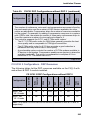
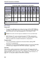
Initial Setup
15. In the License and Option Selection screen, enter the Application
Record ID and select Retrieve Licenses:
-
If licenses exist, the screen is updated with the Purchased Options.
-
If the licenses do not exist, the Software Installer connects to the
AMC to obtain the licenses.
-
If the licenses do not exist and the AMC cannot be reached, the
Software Installer creates a batch file that contains the options. You
can reconnect to the Software Installer later to run the batch file to
license the options.
Tip: Enable the IP Networking option and MiTAI/TAPI Computer
Integration options.
Tip: When using the License and Restore option, you must restore from
a database backup file.
16. To program the local system as the Designated License Manager,
enter the GARID (Group Application Record ID) and click Retreive
Licenses. If the AMC can be reached and the licenses exist, the
screen is updated. If not, the Software Installer creates a batch file to
facilitate offline registration.
17. Allocate licenses to the Purchased Options.
Note:If license sharing is enabled, the total number of licenses available for
allocation is determined when the system joins an application group that has
a Designated License Manager.
18. Click Next and enter the Configuration Options.
19. Click Next.
20. Click Start.
Automatic Sync via System Administration Tool
1. In the System Administration Tool, access the License and Option
Selection form and click Change.
2. Enter the Application Record ID, and then click Retrieve Licenses.
Tip: Enable the Networking Option and MiTAI/TAPI Computer Integration
options.
33
3300 ICP Technician’s Handbook
3. Click Next to display the In Progress screen. Click Save to commit
your changes.
4. Click Start. After the reboot is complete, log into the System
Administration Tool and issue the DBMS Save maintenance
command.
5. Issue the DBMS Stat command to verify the DBMS Save and to
ensure that the DBMS_Initialized Flag is on.
Manual License and Options Entry via MCD Software
Installer Tool
Note:This procedure is not supported on the MXe Server. Refer to the
Software Installer Help for the offline licensing procedure for the MXe
Server.
1. Launch the Software Installer and select either the MXe Server check
box or the 3300 ICP check box to get to the Login screen.
2. Enter the Iogin information and the IP addresses. Click Configure.
Tip: If the SI is connecting to the MXe from behind a firewall, the firewall must
be configured to allow https (443), ftp (20, 21), and ssh (22).
Note that a DNS server is required.
3. If the software load you need is a higher release than the software
pre-loaded on the MXe Server’s hard drive, or if you are installing on
a 3300 ICP, click Perform Upgrade.
If the pre-installed software on the MXe server is the latest release,
click License and Restore.
4. If you selected Perform Upgrade, type in or browse to the location of
the upgrade software.
5. Click Next to get to the License and Options Selection dialog.
6. Allocate the number of licenses in the appropriate fields.
7. Select the appropriate Country variant and Configuration Options.
8. Click Save to commit your changes to the database.
9. Reset the controller (page 129).
34
Initial Setup
Manual License and Options Entry via System
Administration Tool
Note:This procedure does not apply to the MXe Server.
1. In the System Administration Tool, access the License and Option
Selection form, and click Change.
Note:In Release 6.0 and later, you will see an Application Record ID field
at the top of the form. Leave this field blank.
2. Select the appropriate Country variant and Configuration Options, and
fill in the fields as required (see your Mitel Options sheet). For more
information, click Help.
Tip: When you Change and Save in the License and Option Selection form
(prior to Release 7.0), an error message that references “sysid # 65535”
means that the SysID or i-Button is not installed or not seated correctly.
Tip: Enable Networking Option and Mitai/Tapi Computer Integration.
3. Click Save to commit your changes to the database.
Time: The Save procedure can take approximately three minutes.
4. Reset the controller (page 129).
35
3300 ICP Technician’s Handbook
Install the Online Help (Optional)
You can install the online Help on all 3300 ICP controllers with the
exception of the AX controller using the Software Installer. For the AX
controller, you must install the Help either on an external web server or
locally on a PC.
To install online Help on a remote web server:
1. Copy and unzip the Help.zip file from MOL to a folder on the web
server. You can also obtain the Help from the eDocs web site
(http://edocs.mitel.com).
2. In the Remote Help Server field of the System Options form, enter
the URL for the location of the Help files using the following syntax:
http://<IP address of Remote Server>/help
For example: http://10.117.7.39/help/
3. Click Save.
Tip: If the URL is not correct, Help window will display a “404 Page Not Found”
error.
To install online Help locally on the PC:
Tip: If the Help files are installed locally on the PC, the Help buttons will not
link directly to specific topics. Launch the Help separately and navigate to
the desired topic.
1. Copy and unzip the Help.zip from MOL to a folder on the PC.You can
also obtain the Help from the eDocs web site (http://edocs.mitel.com).
2. Open the sysadmin folder and create a shortcut to the
sysadminhelpmain.htm file on the PC Desktop.
3. Double-click the shortcut to launch the Help.
36
Initial Setup
Verify the Operation of the Controller
1. On the Maintenance PC, access the System Administration Tool.
2. In the System Hardware Profile folder, verify that the information in
each of the forms is correct, including the IP address of the E2T for the
MXe system.
3. In Maintenance and Diagnostics, click Alarm Details.
Verify that the following alarms do not appear (if you get an alarm, go
to “Check Alarm State” on page 117):
-
E2T Com (not applicable to the AX, CX/CXi, and CX II/CXi II
controller)
-
DSP
Tip: The next four steps are optional.
4. Connect two IP Phones directly to the controller’s Ethernet ports.
5. Program the IP Phones (refer to the System Administration Tool
Online Help for details).
6. Make a call from one phone to the other.
7. Disconnect the IP Phones from the controller.
37
3300 ICP Technician’s Handbook
38
Chapter 3
Installation and Programming
3300 ICP Technician’s Handbook
40
Installation and Programming
Install Hardware
Determine Controller Module Configuration
The following illustrations include available components for each
controller. Refer to Chapter 6 on page 157 for installation instructions.
Figure 5: Slot Locations for the MXe Controller and MXe Server Card
Table 4: MXe Controller: Supported Modules
Module
MMC1
MMC2
MMC3
MMC4
MMC5
MMC6
FIM
Yes
Yes
Yes
Yes
No
No
T1/E1
Yes
Yes
Yes
Yes
No
No
BRI
Yes
Yes
Yes
Yes
No
No
Page 1 of 2
41
3300 ICP Technician’s Handbook
Table 4: MXe Controller: Supported Modules (continued)
Module
MMC1
MMC2
MMC3
MMC4
MMC5
MMC6
CIM
Yes
Yes
Yes
Yes
No
No
DSP
Yes
Yes
Yes
Yes
Yes
Yes
DSP II
No
No
No
Yes
Yes
Yes
Echo Canceller
Yes
Yes
Yes
Yes
Yes
Yes
Page 2 of 2
Table 5: MXe Server: Supported Modules
Module
DSP
MMC1
MMC2
MMC3
MMC4
MMC5
Up to two DSP modules for additional compression
DSP II
No
No
No
Yes
Yes
Yes
Echo Canceller
Yes
Yes
Yes
Yes
Yes
Yes
Figure 6: Slot Locations on the AX Controller Card
42
MMC6
Installation and Programming
Figure 7: Slot Locations for the CXi Controller
(with an Ethernet L2 Switch)
Note: Only three ASU ports are supported system wide.
Figure 8: Slot Locations for the CX Controller
(without an Ethernet L2 Switch)
43
3300 ICP Technician’s Handbook
Note: Only three ASU ports are supported system-wide.
Figure 9: Slot Locations for the CXi II Controller
(with an Ethernet L2 Switch with POE)
Figure 10: Slot Locations for the CX II Controller
(without an Ethernet L2 Switch)
44
Installation and Programming
Identify Controller Component Options
Table 6: Controller Component and Upgrade Options
Processor Speed
2G
450
450
533
Components
MXe7
Server
AX6
MXe II3
MXe III13
Embedded CIM
—
—
Quad CIM (page 172)
—
FIM (page 170)
—
DSP (page 170)
266
450
CX/CXi
CX/CXi II2
LX
—
—
Echo canceller
(page 170)
—
T1/E1 Framer
(page 171)
—
—
BRI Framer
(page 171)
—
T1/E1 Combo
(page 171)
—
Line Cards (AX, ASU
II) (page 231)
—
—
—
—
—
AMB (MXe)
(page 175)
—
—
—
—
AMB (CX/CXi)
(page 176)
—
—
—
—
—
AMB (CX II/CXi II)
(page 178)
—
—
—
—
—
AOB (CX/CXi)
(page 179)
—
—
—
—
—
AOB (CX/CXi)
(page 180)
—
—
—
—
—
Redundant Power
Supply (page 222)
—
—
Page 1 of 3
45
3300 ICP Technician’s Handbook
Table 6: Controller Component and Upgrade Options (continued)
Processor Speed
2G
450
450
533
Components
MXe7
Server
AX6
MXe II3
MXe III13
Hard Drives
(page 205)
—
RAID controller
(page 223)
—
Redundant Hard
Drives Mxe II/MXe
Server (page 210)
Redundant Hard
Drives Mxe III
(page 215)
Stratum 3 Clock
(page 173)
266
450
CX/CXi
CX/CXi II2
LX
—
—
—
—
—
—
—
—
—
—
—
—12
—8
8
—8
System ID Module
(page 174)
—
—
—
—
—
System i-Button
(page 174)
—
—
System Flash
(page 233)
—
—
—
—
—
Voice Mail Flash
(page 233)
—
—
—
—
—
E2T (page 202)
—
—
—
Application Processor
Card9 (APC-CX(i))
(page 188)
—
—
—
—
—
APC-CX(i) II10
(page 194)
—
—
—
—
—
Application Processor
Card (APC-MXe)
—
—
—
—
—
Upgrading to a
1400-User System
—
—
—
—
Page 2 of 3
46
Installation and Programming
Table 6: Controller Component and Upgrade Options (continued)
Processor Speed
2G
450
450
533
Components
MXe7
Server
AX6
MXe II3
MXe III13
266
450
CX/CXi
CX/CXi II2
LX
Notes:
1. The Quad CIM requires Release 7.1 or later software. The CIM ports on the
MXe Server are not available for use, but the LEDs will continue to flash.
2. The CX/CXi require Release 6.0 or later software. The CX II/CXi II require
MCD 4.0 or later software.
3. The MXe II requires Release 7.0 or later software.
4. Requires the installation of a second processor, the E2T.
5. The embedded CIM is not an option and is not field replaceable.
6. The AX requires Release 7.1 or later software.
7. The MXe Server requires Release 8.0 or later software.
8. The CX II, CXi II and AX controllers use an embedded Stratum 3 Clock, so it
is not field replaceable.
9. The APC-CX(i) is available for the CX or CXi running Rel 7.1+ software.
10. The APC-CX(i) II is available for the CX II or CXi II running MCD 4.0+
software.
11. The Hard Drive 2 pack for the MXe Server comes with one of the hard
drives loaded with the Communications Director software and the other one
blank. Mirror the blank drive before using the Software Installer. See page 211.
12. The MXe Server does not have any digital trunks, so it does not use a
Stratum 3 clock.
13. The MXe III requires MCD Release 4.2 or later software.
Page 3 of 3
Remove Controller Cover
To remove the controller cover:
1. Power down the controller (see page 129).
2. Disconnect all cables.
3. Remove cover as shown in Figure 11 or Figure 12.
47
3300 ICP Technician’s Handbook
Figure 11: CX/CXi, CX II/CXi II - Removing the cover
Figure 12: MXe/MXe Server - Removing the Cover
Install Controller Modules
Read the Safety Instructions before performing the procedures in this
chapter (see “Safety Instructions” on page 3).
Tip: Before installing a 3300 ICP, always read the RN for the software you
are installing (see “3300 ICP Documentation - Mitel eDocs” on page 8).
48
Installation and Programming
1. Shut down the controller (see page 129).
2. Disconnect all cables from the controller.
3. Remove the controller cover (page 47).
4. Remove the module from its packaging.
MXe, MXe Server, CX/CXi, CX II/CXi II
5. Remove the blank module cover at the front of the controller, and
insert the module in an appropriate slot.
6. If you are replacing a defective module, remove the screws and lock
washers and pull up on the module to remove it.
7. Secure the module to the controller using the screws and pillars
provided with the module.
8. Tighten the controller faceplate screw nearest the MMC slot.
9. Replace the controller cover or the controller card.
10. Reconnect the cables to the controller.
11. Power up the controller.
AX
1. Remove the blanking plate (or the old MMC) from the controller by
removing the screws that hold the standoffs to the controller. (The
screws are on the back side of the controller card.)
2. Back off the controller faceplate screw nearest the MMC slot a couple
of turns (because the screw interferes with the removal/insertion of
T1/E1, Quad BRI, Quad CIM, or Dual FIM).
3. Slide the blanking plate out of the opening from the back of the
controller faceplate.
4. Remove the two standoffs (closest to the face plate) from the blanking
plate (or old MMC). Retain the standoffs and screws.
5. Fasten the standoffs to the front of the new MMC.
CAUTION: Proceed with extreme care to avoid damaging components on the controller card.
49
3300 ICP Technician’s Handbook
6. Carefully slide the MMC face plate under the lip of the controller face
plate. See Figure 13. Do not push the MMC past the controller face
plate as shown in Figure 14.
7. Re-install and/or re-tighten the screws.
8. Continue with procedure as described in the specific FRU instructions.
Figure 13: Position module at an angle (AX)
Figure 14: Slide in and seat module (AX)
50
Installation and Programming
Install Controller Stratum 3 Clock Module
To install the clock module in the CX/CXi, and MXe:
Note: The other controllers use the Stratum 3 Clock, but in each case, the
clock is embedded and is not field replaceable. The MXe Server does not
use a Stratum 3 Clock.
1. Power down the controller (page 129).
2. Remove the controller cover (page 47).
3. Remove the screws from the clock module.
4. Remove the clock module.
5. Seat the new clock module onto the main board.
6. Replace the screws that you removed from the clock module.
7. Replace the top cover, and power up the controller (page 24).
Install Controller Hardware
Refer to “Add or Replace Controller FRUs” on page 166 for controller
hardware installation procedures.
Rack Mount the Controller
The rack-mount hardware secures the controller to the rack. The mounting
hardware is shipped with the controller.
MXe (Four-piece Bracket Installation)
1. Position a mounting bracket inside the rack frame at the desired
height. Fasten the mounting bracket to the front of the rack frame with
two screws—one in the top hole, the other in the bottom (see 1 on
Figure 15). Then do the same to fasten the other mounting bracket on
the other side of the rack frame at the same height.
2. Fasten the angle brackets on each side of the cabinet. Align the
brackets with the pre-drilled holes located near the front panel. Use
two screws to fasten each bracket (see 2 on Figure 15).
3. Set the controller cabinet onto the mounting brackets and slide the
controller cabinet into the cabinet (see 3 on Figure 15).
4. Fasten the angle brackets to the rack frame. Install two screws in each
bracket (see 4 on Figure 15).
51
3300 ICP Technician’s Handbook
Figure 15: MXe and CX II/CXi II Controller Rack-Mount 4-Piece
Bracket Installation
MXe (Two-piece Bracket Installation)
1. Attach the mounting brackets to the MXe using the flat head screws
provided.
2. Loosely install one frame mounting screw on each side of the frame:
-
in the bottom hole position of the space that the MXe will occupy.
-
loosely enough that the frame mounting bracket can be dropped
into position, resting on the screw thread (see Figure 16).
3. Position the MXe on the frame, resting the MXe mounting brackets on
the frame mounting screw thread.
-
The MXe will rest on those screws while the remaining screws are
installed.
4. Install two more screws on each side of the frame, in the 3rd and 6th
hole positions.
52
Installation and Programming
5. Tighten all six of the mounting screws.
Figure 16: MXe Rack-mount Screw Placement (2-piece Bracket
Installation)
CAUTION: Remove the MXe from the rack in reverse order.
Loosen the bottom screws before the other screws are
removed.
Never turn the bottom screws while the rack is resting on them.
AX
Tip: The AX controller must be rack-mounted. The chassis is shipped empty
and is light enough to be installed by one person.
1. Mount the rack ears to the chassis front or rear facing, centre or
face-mounted.
2. Attach the other part of the rack-mount kit to the rack.
3. Lift the chassis into the rack and bolt it in place.
4. Install power supplies, controller card, and line cards into the chassis.
5. Attach a permanent ground connection.
Tip: Refer to “Controller Card (AX)” on page 232 for installation instructions.
53
3300 ICP Technician’s Handbook
CX/CXi
1. Peel off the rubber bumper from one of the brackets. Removing the
rubber bumper makes it easier to insert the controller into the rack.
2. Turn the cabinet over and place the bracket on the left side of the
cabinet as shown in Figure 17. The farther you position the bracket
back from the front of the cabinet, the farther the cabinet will protrude
from the rack.
3. Place the plate over the bracket.
4. Insert the standoffs on the plate into the holes in the side of the bracket.
Ensure that at least two of the standoffs are in holes on the bracket.
5. Fasten the plate securely to the cabinet with the two screws. Ensure
that the bracket is locked into place.
6. Install the second bracket on the left side of the rack.
7. Turn the controller upright and slide into the rack.
8. Fasten the right bracket to the rack.
Figure 17: CX/CXi Controller Rack-Mount Bracket Installation
54
Installation and Programming
CX II and CXi II
1. Position a mounting bracket inside the rack frame at the desired
height. Fasten the mounting bracket to the front of the rack frame with
two screws—one in the top hole, the other in the bottom (see
Figure 18). Then do the same to fasten the other mounting bracket on
the other side of the rack frame at the same height.
Figure 18: CX II/CXi II Controller Rack-Mount Installation - Attaching
Brackets to Rack Frame
2. Remove the cover from the controller.
3. Fasten the angle brackets on each side of the cabinet. Align the
brackets with the pre-drilled holes located near the front panel. Use
two screws to fasten each bracket (see Figure 19).
Figure 19: Figure 21: CX II/CXi II Controller Rack-Mount Installation
- Attaching Brackets to Controller
55
3300 ICP Technician’s Handbook
4. Replace the cover on the controller.
5. Set the controller cabinet onto the mounting brackets and slide the
controller cabinet into the cabinet.
6. Fasten the angle brackets to the rack frame. Install four screws in each
bracket (see Figure 20).
Figure 20: CX II/CXi II Controller Rack-Mount Installation - Fastening
Angle Brackets to Rack Frame
Wall Mount the CX/CXi and CX II/CXi II Controller
Required parts and tools:
•
Wall mount bracket (supplied)
•
Two #6 screws and washers (CX/CXi) (supplied)
•
Two #4 metric screws (CX II/CXi II) (supplied)
•
Drill, screwdriver(s), and two #10 screws for anchoring bracket to
backer board.
CAUTION: Make sure the wall material is capable of supporting the weight of the unit. It is recommended that you mount
the supplied bracket onto a backer board of 3/4" plywood that
is securely fastened to the wall studs. DO NOT mount the
bracket directly onto drywall (sheetrock). Mitel is not responsible for units damaged as a result of improper wall mounting.
56
Installation and Programming
CX/CXi
To wall mount the CX/CXi controller:
1. Turn the controller upside down.
2. Locate the two holes on the bottom of the Controller as shown
Figure 21.
3. Assemble the two supplied screws and washers, then screw them into
the holes on the bottom of the controller.
4. Mount the bracket onto the plywood backer board as follows:
a. Pre-drill two pilot holes spaced 11.25" (28.58 cm) apart into the
backer board.
b. Orient the bracket over the two holes as shown below.
c. Insert a screw into the hole on the left side of the bracket.
d. Insert a screw into the hole on the slot on the right side of the
bracket.
5. Secure the backer board to the wall studs.
6. Hang the controller onto the bracket as shown below.
Figure 21: Wall-mounting the CX/CXi
57
3300 ICP Technician’s Handbook
CX II/CXi II
To wall mount the CX II/CXi II controller:
1. Turn the controller upside down.
2. Fasten the mounting bracket to the bottom on the controller using the
supplied screws (see Figure 22).
Figure 22: Wall-mounting the CX II/CXi II - Attaching the Mounting
Bracket to the Controller
3. Secure the backer board to the wall studs.
4. Pre-drill two pilot holes spaced 11.25" (28.58 cm) apart into the backer
board.
5. Insert a screw into each pilot hole.
6. Hang the controller onto the screws.
Install Service Units and Cabinets
This section contains detailed information on installing and configuring the
Network Services Unit and the Analog Services Unit for the 3300 ICP. This
section also contains information on configuring embedded analog.
Tip: The MXe Server does not support Network Services Units, Analog
Services Units, embedded trunking or embedded analog.
You can install any of the following Network Services Units (NSUs):
•
Universal NSU (MSDN, PRI/QSIG, T1/D4)
•
R2 NSU
•
BRI NSU.
58
Installation and Programming
You can double the number of Universal and R2 NSUs in a system by
chaining a secondary NSU to each primary NSU connected to the
controller. BRI NSUs cannot be chained.
Some NSUs must be programmed with the ISDN Maintenance and
Administration Tool (IMAT) (see “ISDN Maintenance and Administration
Tool” on page 72).
CAUTION: To connect your NSU to the LAN, you must change
the default IP and gateway addresses to match an available
address on the LAN. The default address is
192.168.1.1:ffffff00. See "Program an IP Address into the NSU"
on page 74.
Universal or R2 Network Services Unit
1. Mount and secure the NSU in the desired location.
2. Set the L0/L1 port DIP switches to the appropriate termination mode
and impedance (see Table 31 on page 255 and Table 36 on
page 257). The default is network termination mode. See “Network
Services Units” on page 254 for the location of these switches.
3. Set the Message Link DIP switch to the appropriate position. See
Figure 111 on page 254 for the location of the Message Link switch
and Table 30 on page 255 for settings.
4. Connect a fiber optic cable between the NSU and the controller FIMs.
5. If you are installing a secondary NSU, connect a crossover CAT 5
cable between CIM 1 of the secondary NSU and CIM 2 of the primary
NSU (see Table 33 on page 256 for CIM pinout, and Table 30 on
page 255 for message link dip switch settings).
6. Connect the NSU L0 and/or L1 port to the remote system (the PSTN
or another system). See Table 36 on page 257 for the pinout.
7. For the PRI and R2 protocols, program the NSU using IMAT (see “To
install IMAT on the PC:” on page 72 and “Program NSU from IMAT” on
page 75). Refer to the IMAT Online Help for more information.
8. Connect power to the NSU.
Tip: The NSU software will not load until the NSU programming is complete
(see Step 9 below).
9. Using the System Administration Tool, program the NSU settings on
the controller. In the View Alphabetically list, click Network Services
Unit Configuration. Refer to the Online Help for more information.
59
3300 ICP Technician’s Handbook
Next: Install any other required services units. When all the services units
are installed, go to “Install Telephones” on page 64.
BRI Network Services Unit
Connect the BRI NSU to the controller via a Universal E1 MSDN NSU.
Refer to “Quad BRI Framer” on page 171 for installing embedded BRI.
Tip: Program the Universal E1 NSU before connecting the BRI NSU.
1. Mount the BRI NSU.
2. Connect the BRI NSU E1 ports to the Universal NSU L0/L1 ports (see
Table 32 on page 255 and Table 36 on page 257 for pinouts).
Tip: Use a CAT 5 cable between the BRI NSU E1 port and the Universal
NSU that is running E1 DPNSS. Ensure that the pinout of the cable matches
that of the E1 connector (pins 1, 2, 4 and 5 are connected). A 4-wire CAT 5
cable will only use pins 1, 2, 3, and 6.
3. Connect the BRI NSU to the ISDN devices using a 25-pair cable. See
Table 38 on page 259 for the pinout.
4. Connect the BRI NSU to the maintenance PC:
a. Connect the RS-232 port (RJ-45 connector) on the BRI NSU to a
serial port on the PC.
b. Set up the communications program on COM port 1 or 2 with the
following parameters:
-
Baud Rate: 9600
-
Data Bits: 8
-
Parity: None
-
Stop Bits: 1
-
Flow Control: XON/XOFF
-
Character Set: ASCII
5. Connect power to the BRI NSU.
6. On the PC, program the BRI NSU using a VT100 emulator (see TB
#58004741, “Basic Setup Guide for the MC268 BRI card”).
Tip: Although the TB is written for the SX-2000 system, the parameters
described are also applicable to the 3300 BRI NSU.
60
Installation and Programming
Analog Services Unit
This procedure applies to the ASU, the Universal ASU, and the ASU II
(compatible only with Release 7.0 or later software). Ensure that there is a
free CIM port on the controller.
ASU II mounting instructions:
•
For rack mounting (rear or front facing), do not install the feet.
•
For wall mounting, install only the two bottom feet.
All ASUs:
1. Mount the ASU. Refer to page 221 for ASU II line card installation
instructions.
2. Connect a Crossover Category 5 cable with RJ-45 connector to the
CIM port on the ASU and a free CIM port on the controller (see
Table 33 on page 256).
Tip: The ASU can be located up to 30 meters (100 feet) away from the
controller. The interface uses a single standard 8-pin modular jack consisting
of 2 balanced signal pairs, and is located on the front of the unit.
3. Complete telephony cabling for the ASU (see Table 42 on page 263).
4. For the Universal ASU, complete the Music on Hold and Paging
cabling if required. See Table 44 and Table 45 on page 265.
5. Connect power to the ASU. Once the CIM link synchronizes, the CIM
LEDs turn on. The controller detects the ASU, and the application
software downloads and starts immediately.
6. Using the System Administration Tool, program the ASU settings on
the controller. Refer to the System Administration Tool Help for
instructions.
Tip: The ONS circuits provide positive disconnect for support of applications
such as door phones.
Tip: Use the LSMeasure Tool to determine the line settings for LS trunks on
an Analog Board or a Universal ASU (refer to the System Administration Tool
online Help).
Next: Install any other required services units. When all the services units
are installed, go to “Install Telephones” on page 64.
61
3300 ICP Technician’s Handbook
Peripheral Cabinet, SUPERSET HUB, and Digital Service Unit
,
Tip: Refer to the Release 7.0 version of the Technician’s Handbook for
SX-2000 peripheral cabinet, SUPERSET HUB, and Digital Service Unit
component installation instructions.
Installing SX-200 Bays
You can connect up to seven SX-200 Bays to the 3300 MXe controller
using CIM or FIM cables. Only SX-200 ELx Bays equipped with BCC III
controller cards and ONS, OPS and DNIC station circuits cards are
supported. See Table 107 on page 377 for a list of supported cards.
Supported peripheral devices are limited to the following:
•
SUPERSET 4000-series DNIC telephones
•
PKM 48, PKM 12 (attached using a SIM1 or SIM2)
•
Analog Interface Module (AIM) connected to a SUPERSET 4025,
4125, or 4150
•
SUPERCONSOLE 1000.
Note: SX-200 Bays are supported in North America only and use the same
loss plan as 3300 ICP devices.
For more information about the SX-200 Bay, including detailed installation
instructions and technical specifications, refer to the SX-200 ICP Technical
Documentation available at http://edocs.mitel.com.
1. If replacing an SX-200 ICP controller, reallocate the facilities
connected to the ONS, DNIC, LS trunk, MOH, Loudspeaker Paging,
and other interfaces to equivalent interfaces on the 3300 ICP as
required.
Note: The SX-200 ICP and 3300 MXe use different connector types for the
Loudspeaker Paging and Alarm circuits. Rewiring will be required. See
“Analog Board (CX/CXi, CX II/CXi II, and MXe Controllers)” on page 251 and
“Controller Alarm Port Pinouts” on page 253 for cable connector pinouts and
PLID assignments.
Note: The MXe provides two more alarm facilities (levels and relays) than
the SX-200 ICP. As the installer, you will need to decide how to handle the
alarms—for example, whether to connect the relays to bells or other alerting
devices—and rewire your installation accordingly.
62
Installation and Programming
Note: The 3300 ICP lacks dedicated hardware and software support for the
Door Opener facilities available on the SX-200 ICP. Equivalent functionality
can be provisioned by using the loudspeaker paging feature and the
associated paging relays on the AOB or AMB.
Note: The maintenance port on the SX-200 Bay is not required as all Bay
programming and maintenance is done through the System Administration
Tool on the 3300 MXe.
2. Remove all trunk interface cards and other unsupported cards from
the SX-200 Bay.
3. Install the SX-200 Bay, including the Bay Power Supply, Bay Control
Card, interface cards, Fiber or Copper Interface Module, and DSP
Module (Single).
Note: The single DSP Module is required to support ONS CLASS/CLIP sets.
4. Complete the peripheral interface cabling. See Table 47 on page 267
for cable connector pinouts.
CIM Connection
5. Connect a Crossover Category 5 cable with RJ-45 connector to the
CIM port on SX-200 Bay and a free CIM port on the controller (see
Table 33 on page 256).
Tip: The SX-200 Bay can be located up to 30 meters (100 feet) away from the
controller. The interface uses a single standard 8-pin modular jack consisting
of 2 balanced signal pairs, and is located on the front of the BCC III card.
FIM Connection
6. Connect a fiber optic cable between the SX-200 Bay and the controller
FIMs.
Note: The same variant of fiber interface module (820 nm multi-mode, 1300
nm multi-mode, or 1300 mn single-mode) must be at both ends.
Note: No other type of peripheral unit (NSU, DSU, etc.) can be connected
to a Dual FIM module that is being used by a 200 Bay. The only type of
unit allowed is another 200 Bay.
63
3300 ICP Technician’s Handbook
7. Power up the SX-200 Bay. Once the CIM or FIM link synchronizes, the
CIM or FIM LEDs turn on. The controller detects the Bay and
downloads firmware to it. After the download, the Bay is automatically
started.
8. Using the System Administration Tool, program the SX-200 Bay
settings on the controller. Refer to the System Administration Tool
Help for instructions.
Install Telephones
This section contains information on installing telephone sets, consoles,
and other peripherals.
The 3300 ICP supports a number of IP, DNI, analog and wireless phones,
as well as conference units, programmable key modules, and attendant
consoles. The CX/CXi and CX II/CXi II controllers only support IP and
analog phones.
If you have a peripheral cabinet with analog/DNIC phones connected to it,
program those telephones using the System Administration Tool.
Tip: You cannot use the Group Administration Tool to modify programming
for SUPERSET 400-series telephones.
Install Telephones, Consoles and Appliances
Refer to each device’s Installation Guide (included in the telephone
package) to install the devices.
Note: Each IP Phone must be directly connected to an L2 switch port. DO
NOT connect them in series (daisy-chaining) using the 2nd LAN port in
the phone. If daisy chained, a problem with one phone can affect all the
others in the chain. Also, all chained phones share the same bandwidth.
Note: If you intend to rely on LLDP VLAN Discovery in the network, you must
first upgrade the 3300 ICP to Release 7.0 or later and upgrade the IP Phone
firmware to version 2.0.0.18 or later.
Note: LLDP-MED non-compliant telephones cannot use LLDP for VLAN
discovery. They must use DHCP VLAN discovery. Non-compliant sets are:
5001, 5005, 5010, 5020 IP Phones, 5140 IP Appliance, 5201, 5205, 5207,
5215 (single mode), 5220 (single mode), 5230 IP Phones, 5240 IP Appliance,
5485 IP Pager, and 5550 IP Console keypad.
64
Installation and Programming
IP phone firmware is automatically downloaded from the 3300 controller to
the IP Phones (requires a DHCP server configured with options 128-133).
You can also download firmware to the telephone by plugging it directly
into an Ethernet port on the 3300 controller. The controller must be running
Release 7.0 or later to provide LLDP-compliant firmware to the telephone.
Note: When a resilient hot desk device rehomes to a switch that has newer
device firmware, the user (including hot desk ACD agents) is automatically
logged out toallow the firmware upgrade to proceed
Install Line Interface Modules
The Line Interface Module (LIM) provides analog operation to the 5220 IP
Phone (Dual Mode), 5224 IP Phone, 5235 IP Phone, 5330 IP Phone, 5340
IP Phone, or 5360 IP in the event of an IP connection failure. Follow the
instructions in the Installation Guide that is included in the module package
to install a Line Interface Module. Refer to “Program Emergency Services
for a Line Interface Module” in the System Administration Tool Help.
Install and Configure Music on Hold
There are three types of Music on Hold available to the system,
embedded, analog, and digital. Program music on hold in the System
Administration Tool. Refer to the online Help for instructions.
Note: The MXe Server supports embedded MOH only.
Embedded Music on Hold is provided by audio files that are imported into
a single controller using the System Administration Tool or into multiple
controllers using Enterprise Manager.
An Embedded Music on Hold (MOH) source in use consumes an E2T
resource and each MOH session consumes an E2T resource.
Analog Music on Hold is provided by an external music source
connected to any one of the following:
•
Music on Hold connector on the back of a Universal ASU (see
Table 44 on page 264)
•
Music on Hold connector on a peripheral cabinet E&M trunk card
Digital Music on Hold is provided by an external music source connected
to a DNIC Music on Hold/Pager Unit (DMP). A peripheral cabinet is
required. The DMP is connected to a DNI line card.
65
3300 ICP Technician’s Handbook
Installing a DNIC Music on Hold/Paging Unit (DMP)
Tip: To reduce the risk of hum or other interference, install the DMP close to
the music source or paging amplifier and keep the cables to and from the unit
as short as possible. If “none” balanced input or output equipment is used,
you may need a balancing transformer (not supplied by Mitel).
To install DNIC Music on Hold (not supported on the AX, CX/CXi,
CX II/CXi II, MXe, or SX-200 Bays):
1. Install a DNI line card in a peripheral card slot.
2. Attach the circuit tip and ring leads to the 25th pair of the DMP.
3. Attach the balanced music source to the 7th pair of the DMP via the MDF.
To install a DMP for Paging (not supported on the AX, CX/CXi, CX II/CXi II
or MXe):
1. Install a DNI line card.
2. Attach the circuit tip and ring leads to the 25th pair of the DMP.
3. Attach the paging adapter interface to the 9th pair of the DMP.
4. If required, attach the page control inputs of the paging adapter via the
MDF to the 11th and 12th pair of the DMP.
5. Connect the paging adapter to an appropriate power source
(according to the manufacturer’s instructions).
6. Connect the external speakers as required to the paging adapter via
the MDF (according to the manufacturer’s instructions).
Tip: Refer to the 3300 ICP Hardware Technical Reference Manual for
connector pinouts.
Program 5485 IP Paging Unit
Note: See Table 46 for the paging unit pinout and Figure 119 on page
266 for the cross connection wiring.
To program a 5485 IP Paging Unit (this programming procedure provides
a burst of ringing prior to the speech broadcast):
1. Launch the System Administration Tool.
2. In the Multiline IP Sets form
-
66
Program the IP Paging Unit as "5010 IP".
Installation and Programming
-
Enter the MAC address.
3. In the Feature Access Codes form (optional)
-
Assign a code to Direct Page Paging.
4. Multiline Set Keys form (optional)
-
Program a Paging key.
5. Interconnect Restriction Table
-
Ensure that the station is not restricted from Paging.
To program Group Page with the IP Paging Unit (This programming
procedure does not provide a ring burst prior to the speech broadcast):
1. Multiline IP Sets form
-
Program the IP Paging Unit as "5010 IP".
-
Program the MAC address.
2. Page Groups form
-
Complete all required fields.Symbol Wireless Phones should not
be programmed into paging groups.
3. Class of Service Options form
-
Set the Group Page Accept field to "Yes" for the IP Paging Unit.
-
Ensure that each telephone in the paging group has the Group
Page Allow field set to "Yes".
4. Feature Access Codes form (optional)
-
Assign a Direct Page feature access code.
5. Multiline Set Keys form (optional)
-
Program a Paging key.
6. Interconnect Restriction Table
-
Ensure that the station is not restricted from Paging.
Register IP Devices from the Telephone
Use this procedure to register IP devices with the 3300 ICP database. The
procedure will program the 3300 ICP database with the MAC address of
the IP device.
Tip: Use the System Administration Tool to complete all other set
programming (for example, Class of Service, Interconnect Restriction, Set
Key Assignments, and Class of Restriction).
67
3300 ICP Technician’s Handbook
Before you begin
•
Ensure a Set Registration Access Code and a Set Replacement
Access Code are assigned in the System Options form.
•
Ensure the directory number and device type is programmed in the
Single Line IP Sets form or Multiline IP Sets form.
Register an IP Device
1. Connect the IP device to an RJ-45 Ethernet port on the LAN. For the
CXi and CXi II, connect to a controller Ethernet port.
2. Provide power to the IP device (refer to the 3300 ICP Hardware
Technical Reference Manual at on Edocs (http://edocs.mitel.com) for
power option information).
3. Press * during power-up (to clear any PIN number in memory).
4. Type the PIN number at the prompt on the IP device. Prompts are:
-
non-display IP Phones: solid message light.
-
display IP Phones and IP Appliances: display shows Enter the PIN
number.
Tip: The PIN number is the set registration code followed by the set’s
extension number.
5. Complete one of the following to send the PIN:
-
5001, 5005, 5201 and 5205 IP Phones: press Hold.
-
5010, 5207, 5215, 5020, 5212, 5220, 5224, 5312, 5324, 5530 and
5340 IP Phones: press SuperKey/Settings.
-
5140 and 5240 IP Appliances, 5235 IP Phone: press OK.
-
5230 IP Appliance: press Send.
The set will complete initialization.
Register an IP Device in a Cluster
The registering sequence in a cluster is unchanged provided that:
•
68
the Cluster Element ID programmed in the Cluster Elements form
matches the ICP/PBX Number programmed in the ICP/PBX
Networking form.
Installation and Programming
•
each member of the cluster is programmed with the directory numbers
of the other controllers. This information must be programmed using
OPS Manager.
•
the Set Registration Access Codes and Set Replacement Access
Codes are the same for each controller in the cluster.
•
each IP device is able to retrieve the IP address of one of the
controllers in the cluster.
69
3300 ICP Technician’s Handbook
Program System
Programming Tools
The system includes a number of programming tools:
•
Embedded System Management (ESM) consists of:
-
System Administration Tool that provides a Web-based interface
that trained technicians use to program the system.
-
Group Administration Tool that provides a Web-based interface
to enable administrators to make changes to user information.
-
Desktop Tool that provides a Web-based interface to enable
display IP telephone users to program feature keys on their phone.
•
Mitel Integrated Configuration Wizard, introduced in Release 7.0,
assists you in the initial system programming. After you specify the
system setup, you can save the configuration data for future use or
apply the changes to the 3300 ICP. See the System Administration
Tool online help for installation and configuration instructions.
•
ISDN Maintenance and Administration Tool (IMAT) provides the
programming interface for PRI and R2 protocols delivered via an NSU
or DSU. Embedded PRI via the Dual T1/E1 Framer is programmed
though the System Administration Tool.
•
MCD Software Installer Tool expedites the distribution of 3300 ICP
software by eliminating a number of interactive steps (see page 91).
The tool restores saved databases from Release 6.1 and later. The
Software Installer also enables databases from legacy SX-2000®
LIGHT, SX-2000 MicroLIGHT, 3200 ICP, and 3800 WAG systems to
migrate to the 3300 ICP. (You must use the Configuration Tool or the
OPS Manager to create a database backup for the legacy systems
before they can be restored using the Software Installer.) For current
releases, the Software Installer replaces the Configuration Tool.
•
Configuration Tool restores saved databases and enables legacy
SX-2000® LIGHT, SX-2000 MicroLIGHT, 3200 ICP, and 3800 WAG
systems to migrate to the 3300 ICP. (This is available for systems up
to Rel 6.1 of the 3300 ICP.)
•
IP Phone Analyzer collects performance information about the IP
devices connected to the 3300 ICP. You can use one PC to monitor
the debug and status information of IP phones (see page 73).
•
70
Installation and Programming
Log into the Programming Tools
Embedded System Management Tools
To log into one of the ESM tools:
1. Launch a browser and go to the URL of the 3300 Controller https://<hostname>/main.htm
-
<hostname> is the name or IP address assigned to the Controller
if no DNS is available. Refer to See “Establish Communication with
Controller” on page 25.
-
When connecting to an MXe Server, you must use the System IP
address (default 192.168.1.5) rather than the RTC IP address.
2. The first time you connect, you must install the Mitel Root CA security
certificate (see “Secure Sockets Layer (SSL) and Security Certificate”
on page 118).
3. To log into the 3300 ICP ESM:
-
Type the default Login ID (“system”) and Password (“password”).
-
Select Remember Login ID if you want to save the Login ID on
your computer.
-
Click Log In.
Tip: To prevent unauthorized use, change the Login ID and password the
first time you log in.
4. Click the desired Tool (Desktop, Group Administration, or System
Administration).
5. You will be prompted to install some XML Components when you log
into the System Administration Tool for the first time. At the following
prompt, “Do you wish to install or upgrade the required XML
components?”, click “Install Now”. The install takes less than 30
seconds and you do not need to restart your computer.
Tip: Your PC must have the same subnet address as the RTC IP (for
example, 192.168.1.x) to launch the System Administration Tool. For the
MXe Server, the PC must use the System IP address.
Tip: The system will allow up to five concurrent System Administration Tool
or Group Administration Tool sessions (or any combination of the two)
provided that the initial login browser is closed plus ten concurrent Desktop
Tool sessions.
71
3300 ICP Technician’s Handbook
Note: The System Administration Tool will temporarily lock you out for 15
minutes after three consecutive attempts to log in have failed.
Mitel Integrated Configuration Wizard
Install the Configuration Wizard on a maintenance PC that meets the
following requirements:
•
Windows 2000 or Windows XP Professional operating system
•
JRE (Java Run-time Environment) 1.6.0_1 or later installed
To install the Configuration Wizard onto the maintenance PC:
•
Close all applications running on the PC.
•
Download the MICW Setup.exe file from MOL.
•
Double-click the Setup.exe file. Follow the prompts to install the
program.
ISDN Maintenance and Administration Tool
You can install IMAT on the Maintenance PC or on its own PC (IMAT PC).
Tip: We recommend using an Ethernet connection from the IMAT PC when
running Windows NT 4.0, Windows 2000 Professional, Windows XP, or
Windows 98. For Windows 95/98 (without a NIC), use Dial-up Networking.
To install IMAT on the PC:
1. Close all the applications running on the PC.
2. Obtain the IMAT software from MOL or insert the 3300 ICP/MCD
software CD-ROM in the CD drive (applies to MCD 4.x and earlier).
3. For CD-ROM-based software only, open the Tools folder, then the
Disk 1 folder.
4. Double click the Setup.exe file. The installation program starts. Follow
the prompts to install IMAT.
5. Connect the NSU Ethernet port directly to the NIC of the PC using a
crossover cable or connect the NSU Ethernet port to the network.
Tip: Refer to the IMAT online help for LAN connection details. If you're using
a dial-up connection, see “Installing System Software on the FTP Server” on
page 106.
72
Installation and Programming
To launch IMAT on the Installation/Maintenance PC:
•
On the Start menu, point to Programs, and click IMAT.
IP Phone Analyzer
To install the IP Phone Analyzer
•
See page 127.
To launch the IP Phone Analyzer:
•
On the Start menu, point to Programs, and click Mitel IP Phone
Analyzer (see page 127 for details).
Mitel Standard Linux Server Manager
Before you can launch the MSL Server Manager, you must configure the
3300 ICP and APC to support MSL. For this procedure, refer to the
3300 ICP System Administration Tool Help.
Note: To launch the MSL Server Manager, you must know the IP address
of the APC.
To launch the MSL Server Manager:
1. In an Internet browser window, go to the following URL:
https://<IP address of APC>/server-manager/.
2. Enter the user name and password the MSL (as configured in the
System Administration Tool).
For more information about MSL, refer to the Mitel Standard Linux
documentation on Edocs (http://edocs.mitel.com).
Configure NSU via IMAT
The ISDN Maintenance and Administration Tool (IMAT) software is used
to program PRI and R2 cards and Network Services Units. IMAT is also
used to install PRI card and R2 card software.
Tip: IMAT is not applicable for the CX/CXi and CX II/CXi II controllers.
Tip: IMAT is not needed to program Embedded PRI, T1/D4, and QSIG (dual
T1/E1 framer module or T1/E1 combo module in the controller).
73
3300 ICP Technician’s Handbook
Tip: You must use the latest release of the IMAT software. Refer to Table 17
on page 138 for information on the correct database version for the 3300
software load you are using.
Program an IP Address into the NSU
You must change the IP and gateway addresses to match an available
address on the LAN.
Tip: If you have an MXe Server on the same network, you must change
the NSU IP address because it will conflict with the default address of the
MIPS IP on the MXe Server.
To program the IP address that IMAT will access:
1. Program the PC’s serial port with a baud rate of 38400.
2. Connect the IMAT PC to the NSU serial port.
3. Establish a terminal session with the NSU card.
4. Reboot the NSU.
5. Press any key during auto-boot to halt the boot process.
6. At the [MC269AA Boot]-: prompt enter C.
7. Change the boot parameters, inet on ethernet (e) :
192.168.1.1:ffffff00 and for gateway inet (g) : 192.168.1.251 default
values to the values provided to you by your LAN administrator.
8. For all other settings, press ENTER to accept the default.
74
Installation and Programming
9. At [VXWorks Boot], type @, or press the Reset button on the
controller.
10. Connect the NSU Ethernet port to the LAN.
Dial-up Connection of the IMAT PC to the NSU
For Windows 95 and Windows 98, refer to "Installing System Software on
the FTP Server" on page 106.
For Windows 4.0, Windows 2000 Professional, or Windows XP without a
NIC, refer to IMAT Online Help for Dial-up connection details.
Program NSU from IMAT
To log into IMAT
1. Launch IMAT from the Start menu or the desktop (ignore any
message about username configuration error).
2. On the File menu, select Connect to Remote Site.
3. Click to select Ethernet Network Card in the Connection Medium
field.
4. Refer to the IMAT online help for programming instructions.
To exit the IMAT application:
1. Save any open databases.
2. On the File menu, click Exit.
Tip: Refer to Appendix G for the following Windows 95/98 procedures:
"Physically Connecting the PC to an NSU" on page 402, and "Creating a
Dial-Up Network Connection on Windows 95/98" on page 402.
75
3300 ICP Technician’s Handbook
Program the Controller DHCP Server (MXe, CX/CXi,
CX II/CXi II)
Note: DHCP options 128-133 used to configure Mitel IP endpoints have been
reclassified as public options by the Internet Engineering Task Force (see
RFC 2133 and RFC 3925). To comply with the change, Mitel recommends
using either option 43 or 125, depending on the server's ability to support
them and on administrator preference. (The embedded server supports both
options with 125 as the factory-programmed default.) The old options can still
be used to provide backward compatibility with IP sets that have yet to be
upgraded with firmware that supports the new options. After the upgrade, the
old options may be removed to prevent future conflicts with standard use or
other vendors' use of these options.
Note: Ensure that all LLDP-compliant telephones are upgraded to firmware
version 2.0.0.18 or later before you use LLDP on your network for VLAN
Discovery.
Note: LLDP-MED non-compliant telephones cannot use LLDP for VLAN
discovery. They must use DHCP VLAN discovery. Non-compliant sets are:
5001, 5005, 5010, 5020 IP Phones, 5140 IP Appliance, 5201, 5205, 5207,
5215 (single mode), 5220 (single mode), 5230 IP Phones, 5240 IP Appliance,
5485 IP Pager, and 5550 IP Console keypad.
Note: IP sets require a firmware upgrade to support the new DHCP options
introduced in Release 7.0; otherwise, the sets will fail to boot. Such failures
can occur, for example, in a resilient cluster of mixed software releases or
when sets with old firmware are added to a controller after it was upgraded
to Release 7.0. For the sets to boot, DHCP options 128-133 must be present
in the DHCP server. After the sets have booted, options 128-133 may be
removed to avoid future conflicts with standard use or other vendors’ use of
these options.
For additional information on programming DHCP settings for the
3300 ICP, refer to the System Administration Tool Online Help.
To use an external DHCP Server, do not enable the internal DHCP server
and refer to “Configuring External DHCP Settings for E2T” on page 283 for
instructions.
Tip: You may need to change the IP address of your PC to match your
customer’s network.
76
Installation and Programming
1. On the Maintenance PC, access the System Administration Tool (see
"Log into the Programming Tools" on page 71).
2. Select View Alphabetically in the view drop-down list.
3. Click DHCP Subnet form, enter the subnet name, IP address and bit
mask.
4. In the DHCP Static IP form, enter a static IP address for the E2T using
the information in Table 50 on page 276. Assign IP addresses to
specific devices by using the MAC address of the device. Assign a
static IP Address to any IP Console in a cluster.
5. In the DHCP IP Address Range form, program the scope using the
information in Table 51 on page 277. Also see Table 48, “Reserved IP
Addresses,” on page 271.
6. In the DHCP Options form, program the options listed in Table 52 on
page 278 for the scope you just programmed. Always create the
following options:
-
3 Router, IP address
-
125 Vendor-Identifying Vendor-Specific Information or Option 43
Vendor Specific Information. Option 125 is the preferred option
-
66 TFTP Server, IP address format
-
67 Boot file, string value (always /sysro/E2T8260)
If there are 5230 IP Appliances, create the following options:
-
6 DNS Server, IP address format
-
44 NetBIOS Name Server, IP address format
7. In the DHCP Lease Viewer form, ensure that there is no DHCP IP
Address Lease for the IP Console MAC Addresses. If there is, delete
it and then power off and power on the device.
8. In the DHCP Server form, enable the internal DHCP server.
77
3300 ICP Technician’s Handbook
To use an alternative DHCP server:
1. In the DHCP Server form, disable the internal DHCP server.
2. Program your DHCP server with options 128-133.
3. Upgrade the IP Phones/ firmware to 2.0.0.18 or later.
4. Program your DHCP server with the following options:
-
43 Vendor Specific Information, string value OR
-
125 Vendor-Identifying Vendor-Specific Information, string value.
5. Delete options 128-133.
Program LS Trunk Settings via LS Measure Tool
Use the LS Measure tool in the System Administration Tool to program the
line settings for Loop Start (LS) trunks that are connected to the AX
Controller Card Chassis, Analog Main Board, Analog Option Board, or
ASU II. The LS Measure Tool supports the following tests:
•
Individual or Batch Line Quality Test
•
Individual or Batch Distortion/Echo Test
The Line Quality Test allows you to obtain the optimum Balance Network
Setting and Trunk Category for each LS trunk, based on the signals
received from the CO. These settings are then programmed into the
Analog Trunks form of the LS trunks to reduce the possibility of echo and
audio level issues between the trunks and IP phones.
The Distortion/Echo test should only be run at the request of Mitel
Technical Support.
Refer to the following book in the System Administration Tool online help
for instructions: Programming -> Programming Trunks -> Using the
Line Measure Tool.
LS Trunk Selection in the UK
Poor audio quality may be experienced if the incorrect subscriber line has
been provided by the carrier.
To ensure that the correct lines are provisioned in the UK, the installer or
system administrator should request that the Telco (e.g. BT), or carrier,
provide trunks that are compatible to System X line type ‘0’ (Subscriber
lines) or line type ‘3’ (business PBX/PABX lines).
78
Installation and Programming
Both types of lines will work satisfactorily with the 3300 ICP, however line
type ‘3’ is the preferred line type for connecting a PBX/PABX.
Configure Analog Music On Hold/Paging
The 3300 ICP supports
• Analog Music on Hold
• Digital Music on Hold (via a DMP)
• Embedded Music on Hold
Refer to the System Administration Tool online help for instructions on how
to program Digital Music on Hold or Embedded Music on Hold.
To program Analog Music on Hold:
1. Launch the System Administration Tool
2. In the System Options form
- Set the Music On Hold option to "Yes".
- (Optional) Class of Service Options form.
3. In the E&M Trunk Circuit Descriptors form
- Set the Outgoing Start Type parameter to "Immediate".
- Set the Transmission Facility parameter to "2 wire".
- Set the 2 Wire Balanced Network Setting parameter to "600".
- Set “Perform Seize Test on Out-of-Service Trunks” to "No".
- All other parameters may be any value.
4. In the E&M Trunk Assignments form
-
Ensure that the trunk number is unique. The service number, E&M
trunk circuit descriptor number, and the interconnect number may
be the same as other E&M trunks.
5. In the System Access Points form
-
Set "Music Source" to "External".
In the "Music Source Port - Location ID" field, enter the PLID of the
E&M trunk circuit.
Note: Music on Hold can be assigned to either of the first two ports on a
Universal ASU E&M card or to the E&M port on the Analog Main Board
(AMB) (on a controller with embedded analog). Only one Music on Hold
source is permitted per system.
79
3300 ICP Technician’s Handbook
6. If you assigned Music on Hold to an E&M port on the AMB (on a
controller with embedded analog) reboot the controller to start Music
on Hold operation. Or, if you assigned Music on Hold to a port on a
Universal ASU E&M card, reload the Analog Services Unit to start
Music on Hold operation.
80
Chapter 4
Software Installation
3300 ICP Technician’s Handbook
82
Software Installation
About Installing and Upgrading Software
You can install software manually or you can install it using the MCD
Software Installer tool. The software installation process formats the
hard drive and installs new software.
Note: You can automate the process of downloading, installing, and
activating software by programming scheduled events in the System
Administration Tool. For details, refer to “Software Events” in the 3300
System Administration Tool Help.
To upgrade the controller software or to install a software patch, you must
use the latest release of the Software Installer. You can upgrade multiple
controllers simultaneously over the LAN.
Perform remote upgrades and installations by connecting to the customer
corporate LAN or through the 3300 ICP WAN port. Refer to “Getting
Started” in the Software Installer Tool Online Help for details.
Tip: Before installing new software on the 3300 ICP, read the RN for the
software you are installing (see “3300 ICP Documentation - Mitel eDocs” on
page 8). Find out if any other software or firmware components of the
3300 ICP need to be upgraded to work with the new software.
CAUTION: If you decrease or increase the number of IP User
Licenses, follow the instructions in Table 10 to avoid losing all
your data.
Software Installation Requirements:
Installation/Maintenance PC requirements (page 13)
IP address of the 3300 ICP (System IP for the MXe Server; RTC IP for
all other controllers)
3300 ICP username and password
3300 ICP software CD (or a copy of the 3300 ICP software)
Mitel MCD Software Installer Tool (for a true upgrade)
3300 ICP Mitel Options Password (page 8)
Database backup with voice mail messages (page 130)
MXe Server only: If installing Mitel Standard Linux (MSL) and Mitel
Communications Director, you must have the Mitel Communications
Director Installation CD, and an external CD/DVD drive.
83
3300 ICP Technician’s Handbook
Tip: You need a new Options Password to change the purchased options
or perform an upgrade for a major software release. You do not need a new
password to change the configuration options.
84
Software Installation
Install System Software Manually
Note: This procedure applies to all platforms except the MXe Server. To
install software on the MXe Server, see “Installing MSL Software on an MXe
Server” on page 106.
Use this manual procedure to install software
•
on systems with Release 3.3 software or earlier
•
on systems that have no software installed on the hard drive
•
when replacing a hard disk with one that has no software installed on it
•
when replacing the flash card in an AX controller, or
•
when upgrading software from Release 3.3 to any later release.
See Table 9 on page 101 for other scenarios that require manual software
installation. In all other cases, we recommend that you use the MCD
Software Installer.
Time: The complete manual install procedure takes approximately 2 hours
for an average-sized database (50-100 MB) and approximately 4 hours for
a large database (600 MB), including the database restore.
CAUTION: The software install procedure will format the
controller hard drive and install new software. All system settings, including voice mail messages, will be erased so you
must back up your database (page 130). If you do not have a
database backup to restore, you will have to reprogram the
system.
The manual upgrade/install procedure consists of the following steps, all
of which must be completed in order:
Tip: Ensure that no one else makes changes to the database once you’ve
backed it up. Any changes not included in your backup will be lost when the
system is restored.
Tip: If a Security Information Warning pop-up window appears during this
procedure, click Yes to continue.
Tip: You can connect directly to the controller through an Ethernet port. You
can also connect to the controller through the LAN.
85
3300 ICP Technician’s Handbook
1. Back up the 3300 ICP database to the Installer PC (page 130).
CAUTION: If you have a Universal NSU with a PRI database,
you may need to convert that database before you begin the
upgrade. Refer to “Converting a PRI Database on a Universal
NSU” on page 138 and the RN for conditions.
2. Install the software on the FTP Server (page 106).
3. Connect the maintenance PC to the controller (page 13).
4. Launch your VT100 emulator communications program.
5. Power up the controller.
6. Stop the controller from booting by responding to the prompt:
-
Press <SPACE><SPACE><SPACE> to stop auto-boot AFTER
countdown starts (Release 5.2 and later)
-
Press any key to stop auto-boot (prior to Release 5.2).
7. At [VXWorks Boot], type c, and press ENTER.
8. For each setting shown in bold (Table 7 below), type the table value,
then press ENTER. For all other settings, press ENTER to accept the
default value.
Tip: The VXWorks parameters are case-sensitive.
Table 7: VxWorks Settings
Prompt
Value
Note
boot device
qefcc
(CX(i) II and MXe III)
—or—
motfcc
(all other controllers)
Boot device is Network.
Note: The CX(i) II and MXe III
accept motfcc but automatically
convert it to qefcc on the next
system reboot.
processor number
0
Not used.
host name
bootHost
file name
Boot_Install
Boot location and file name.
Page 1 of 2
86
Software Installation
Table 7: VxWorks Settings (continued)
Prompt
Value
inet on ethernet
(e)
Note
IP address and subnet mask (hex)
for controller RTC (for example,
134.199.63.11:ffffff00). Obtain it
from your IT administrator.
inet on backplane
(b)
host inet (h)
IP address of FTP Server. Used
for software upgrades.
gateway inet (g)
IP address of the end user’s
default gateway for the 3300 ICP
(must be outside the DHCP
range).
user (u)
ftp
User name of FTP Server.
ftp password (ftp)
ftp
Password of FTP Server.
flags (f)
0x0
Uses host inet IP address.
FixPartition
Used to partition a hard drive or
AX flash card that has no system
software on it.
target name (n)
startup script (s)
other (o)
Note: If the hard disk comes
without software, you must use
“FixPartition” to partition the hard
disk for the install.
Note: During the installation
process, the system automatically
changes this parameter to qefcc
(CX(i) II and MXe III) or motfcc (all
other controllers).
Page 2 of 2
9. At [VXWorks Boot], type @, or press the controller Reset button.
Time: The system takes approximately 30 minutes to format the hard drive
and install the software.
87
3300 ICP Technician’s Handbook
10. If you have an E2T card, do the following:
•
Launch Internet Explorer and type the IP address of the controller (for
example, http://<RTC IP address>). Log into the 3300 ICP ESM using
the default username (system) and password (password).
Tips:
• The Installer PC must have the same subnet address as the RTC IP (for
example, 192.168.1.n) to launch ESM.
• If login fails or you experience difficulty excuting maintenace commands,
it may be because the system is not finished loading. Wait a few minutes
and try logging in again.
• If you enter an incorrect username/password three times in a row, the
system will prevent you from attempting to log in with this
username/password for a period of 15 minutes.
•
Enter the UPGRADEBOOTROM E2T command.
11. Complete the installation using the System Administration Tool (see
Step 12) or the Software Installer Tool (see "Install System Software
using the Software Installer" on page 91).
12. PING the controller to verify that you have established a connection.
13. Set the options in the License and Option Selection form according
to your purchased Mitel options. Refer to your records or go to the
AMC (page 29).
Tip: Since the installation of new software erases all of your system settings,
you must complete this form even if you have not purchased any new options.
a. Access the Software Administration Tool.
a. Select View Alphabetically in the view drop-down list.
b. Click License and Option Selection. Click Change in the top left
corner.
c. Enter the information for the system options you purchased.
d. Enter your Mitel Options Password in the Password field.
e. Change the Configuration options as needed.
Tip: We recommend that you enable Networking Option and Mitai/Tapi
Computer Integration.
f. Click Save. A pop-up window instructs you to restore or reboot.
Click OK to close the window.
88
Software Installation
14. Restore the database backup (page 132). Not all steps are required.
15. If you do not have a database backup:
-
Reset the controller (page 129).
-
Access the System Administration Tool.
-
In the View Alphabetically list, click Maintenance Commands.
-
Issue the dbms save maintenance command.
-
Enter the dbms stat command to verify the DBMS save, and that
the DBMS_Initialized flag is on.
Tip: Complete the following Maintenance Checks only after a restore.
CAUTION: Do not reset system components while
executing the following checks.
16. Verify that none of the NSUs are loading. If they are, wait until they
have finished loading (L0/L1 LEDs stop flashing).
17. When the system has finished resetting, log back into ESM.
18. In the View Alphabetically list, click Maintenance Commands.
19. Enter the dbms stat command to verify the DBMS save, and that the
DBMS_Initialized flag is on.
20. Issue the Type *.dr.logfile_1 command to display the log file created
during the Data Restore. When the checks are complete, review the
log to ensure there were no errors during the restore procedure.
21. Issue the mess sub command to check the programmed NSU links;
they should be OPEN. If any programmed links are in SCAN, check
the LINK STATUS LEDs; if the amber LEDs are flashing, this means
that the NSUs are writing to the RAM DISK.
22. Upgrade the IP telephones and force lease renewals. Issue the LOAD
IPDevice 1 to X maintenance command (where X represents the last
IP device number) to upgrade the IP phones.
23. If the system has a peripheral cabinet with DNI line cards, enter the
Load x x x command to load the DNI cards and the latest DNI line
load.
89
3300 ICP Technician’s Handbook
Tip: If you have an IP console, you must:
- Cycle the power on the IP TKB (key pad).
- Upgrade the IP Console software (if required).
- Renew the IP address for the console PC (if required).
Power down or at the DOS prompt enter ipconfig /release and
then ipconfig /renew.
24. Back up the database (page 130).
90
Software Installation
The MCD Software Installer Tool
Install the MCD Software Installer Tool
You can install the MCD Software Installer Tool on the
Installation/Maintenance PC, or on its own PC (see page 13 for PC
requirements).
Tip: Assign a static IP address to the PC running the Software Installer.
Tip: Ports required by the Software Installer:
Prior to Release 7.0 - port 2002 and ports 49500-49549
Release 7.0 and later - port 443.
To install the Software Installer:
1. Download the MCDSoftwareInstallerSetup_<version>.exe file from
MOL (MCD 5.0 or later) or insert the MCD software CD-ROM disk (disk
1 for R8.0 or earlier; disk 2 for R9.0 to MCD 4.x) into the Installer PC’s
CD drive.
2. For CD-based software only: Open the Tools folder, then the Mitel
Communications Director Software Installer folder.
3. Double-click the MCDSoftwareInstallerSetup_<version>.exe file.
Follow the prompts to install the Software Installer.
To launch the Software Installer:
• On the Start menu, point to Programs, and then click MCD Software
Installer.
Tip: Refer to “Enable Licenses and Options” on page 29 to manage software
licenses online.
Install System Software using the Software Installer
CAUTION: If you have a Universal NSU with a PRI database,
you must convert that database before you begin the install
(see “Converting a PRI Database on a Universal NSU” on
page 138).
91
3300 ICP Technician’s Handbook
To perform a full or new install with the Software Installer:
1. Launch the Software Installer.
2. Choose:
-
3300 ICP to install software on a 3300 ICP, or
-
MXe Server to install software on the MXe Server
-
Click Next.
3. In the SI Login screen, complete the fields:
-
For the 3300 ICP:
System Login ID
System Password
3300 ICP System IP Address
-
For the MXe Server:
APC-MXe IP Address
APC Login ID (Linux administrator login ID)
APC Password (Linux administrator password)
System Login ID
System Password
4. Click Configure.
5. If you chose 3300 ICP:
-
Select Perform Full Install
-
Click Offline or Online
If you chose MXe Server:
-
Click on License and Restore
Tip: If you are installing Rel 8.0+ onto a Rel 8.0 or Rel 8.0+ software load,
you do not need to install from an external FTP server.
6. If you are using the 3300’s internal FTP server, type in or browse to
the location of the upgrade load.
Otherwise, enter
-
FTP Server IP Address
-
FTP Account Name
-
FTP Password
7. Click Next.
8. Select the desired install options.
92
Software Installation
9. Click Next.
10. In the License and Option Selection screen, enter the ARID
(Application Record ID) and click on Retrieve Licenses.
If you chose 3300 ICP, you will be able to manually enter some of the
license options if you wish.
If you chose MXe Server, you will not be able to enter any of the
licenses. Clicking Retrieve Licenses will attempt to fill in the license
options.
•
If licenses exist, the screen will be filled in with all of the licenses
and options.
•
If licenses do not exist, the Software Installer will try to connect to
the AMC to get licenses.
•
If licenses do not exist and the AMC is unreachable, then:
-
The Software Installer will create a batch file that contains the
options, and
-
You can reconnect to the Software Installer later to run the
batch file to license the options.
Tip: You will not be able to continue with the installation until the licenses
have been obtained.
11. Once the licenses have been obtained, click Next.
12. Click Start on the Installation In Progress screen to begin the
installation.
Time: This process takes approximately 45 minutes.
93
3300 ICP Technician’s Handbook
Upgrade System Software
The following conditions apply to both online and offline upgrades:
•
You will not be able to use the System Administration Tool until the
upgrade is complete or until you cancel the upgrade using the
Software Installer.
•
You will not be able to perform backups until the upgrade is complete
and the activation has been done.
•
The upgrade requires a change to a different set of DHCP options
(43/60 or 124/125) used to configure Mitel IP endpoints. The change
is due to reclassification of DHCP options by the Internet Engineering
Task Force (see RFC 2133 and RFC 3925). The old options can still
be used to provide backward compatibility with IP sets that have yet to
be upgraded with firmware that supports the new options. After the
upgrade, the old options may be removed to prevent future conflicts
with standard use or other vendors’ use of these options. The change
to the new options is automatic for the internal DHCP server.
•
LLDP-MED non-compliant telephones cannot use LLDP for VLAN
discovery. They must use DHCP VLAN discovery. Non-compliant sets
are: 5001, 5005, 5010, 5020 IP Phones, 5140 IP Appliance, 5201,
5205, 5207, 5215 (single mode), 5220 (single mode), 5230 IP Phones,
5240 IP Appliance, 5485 IP Pager, and 5550 IP Console keypad.
Online Upgrade
Note: You can use online upgrade only when upgrading from Rel 8.0 to a
later release. In this case, you can also use the internal FTP server.
Online Upgrade is the default upgrade method for Rel 8.0 and later.
Performing an Online Upgrade means scheduling very little down time for
your upgrade. You can perform most of your upgrade with the system
running. The only downtime will be during the reboot.
In addition, you can do the entire install, and then schedule the reboot
whenever it is convenient. You can close the Software Installer anytime
after the Installer has finished transferring the new files to the 3300. See
Table 8 for more information about closing the Software Installer before
the upgrade is complete.
1. Launch the Software Installer.
2. Choose 3300 ICP or MXe Server and click Next.
94
Software Installation
3. The SI Login Screen will appear. Complete the login and IP
addresses, and click Configure.
4. The Upgrade Screen appears. Click Perform Upgrade. Leave the
Offline check box unchecked.
5. Enter path (or Browse) to the 3300 ICP software.
6. Click Next. Select the desired upgrade options.
CAUTION: If you choose “transfer resilient devices immediately” active calls will be terminated.
Tip: While Data Preservation and Software Activation are in progress, no
database changes will be permitted. No changes will be saved from the time
the Backup starts. This includes changes made from the System
Administration Tool, Enterprise Manager and Desktop Tools.
7. In the License and Option Selection screen, enter the ARID
(Application Record ID) and click on Retrieve Licenses.
If you chose 3300 ICP, you will be able to manually enter some of the
license options if you wish.
If you chose MXe Server, you will not be able to enter any of the
licenses manually. Clicking Retrieve Licenses will attempt to fill in the
license options.
-
If licenses exist, the screen will be filled in with all of the licenses
and options.
-
If licenses do not exist, the Software Installer tool will try to connect
to the AMC to get the licenses.
-
If licenses do not exist and the AMC is unreachable, then the SI will
create a batch file that will allow you to license the controller later,
after you are able to contact the AMC.
Click Next.
Tip: You will not be able to continue with the installation until the licenses
have been obtained.
8. Click Start on the Upgrade In Progress screen.
9. If you didn’t schedule software activation, you must activate the new
software when the installation is complete. Refer to “Complete Online
Upgrade – Software Activation” on page 97.
95
3300 ICP Technician’s Handbook
Cancel or Close an Online Upgrade
You can cancel your online upgrade at any time without affecting system
users. The upgrade is terminated either immediately or after completion of
the current step.
Table 8 lists the impact of closing the Software Installer during an upgrade.
Depending on when you close the Software Installer, you may be able to
resume where you left off by reconnecting later. See “Resume an Online
Upgrade” on page 97.
Table 8: Closing the SI before Upgrade is complete
Software Installer
is closed...
What happens to the upgrade in progress?
... prior to starting
Upgrade
No record of user input will be saved. You will have to
re-enter all the options when you log in to the Software
Installer again.
... during software
file transfer (while
performing the ftp
push)
During the software transfer portion of the upgrade, the
3300 will request that the 3300 send individual files to the
hard drive. When the file transfer is complete, the 3300
will begin unzipping and extracting each file.
If the SI is closed prior to completing the file transfer, the
3300 will remain in a file request state.
The upgrade will not finish because not all of the files
have been transferred to the 3300.
... while the 3300 is
extracting the
software files
The extraction is not complete.
... following the file
transfer
If the user has chosen the option that causes Software
Activation Immediately after the file transfer is complete
or a Software Activation time has been set, then
- The upgrade will finish.
The upgrade will not finish because not all of the files
have been transferred to the 3300.
If the user has chosen to delay the Software Activation,
but has not specified a time for it to run, then
- The upgrade will not finish.
... during the internal
Backup
The 3300 will control the internal backup and all
subsequent steps.
The upgrade will finish.
Page 1 of 2
96
Software Installation
Table 8: Closing the SI before Upgrade is complete (continued)
Software Installer
is closed...
... during the
License
Configuration
What happens to the upgrade in progress?
The 3300 already has all the information it needs to
continue.
The upgrade will finish.
... during the internal
Restore
The 3300 will control the internal restore and all
subsequent steps.
The upgrade will finish.
... during the
activation of the new
load (Swap and
system reset)
The 3300 has all the information it needs to complete the
upgrade process.
The upgrade will finish.
Page 2 of 2
Resume an Online Upgrade
1. Launch the Software Installer.
2. Login and connect to the 3300. If the SI determines that an upgrade is
in progress on the 3300, it will display the In Progress screen.
3. Click on Resume Upgrade.
CAUTION: If you have scheduled an immediate Software
Activation, your controller will automatically reboot when
the upgrade is complete.
Tip: If you click on Cancel instead, the upgrade will stop and the status file
will be removed from the controller. You will start from the beginning again
the next time you launch the Software Installer.
Complete Online Upgrade – Software Activation
Activate the new software when traffic is lowest, and the reboot will have
the minimum impact. Reconnect the controller to the Software Installer.
Click Start Software Activation.
After the upgrade, follow the instructions in “Reprogram external DHCP
servers (required for Release 7.0)” on page 100 to reprogram the DHCP
server(s) to use the new DHCP options.
97
3300 ICP Technician’s Handbook
Offline Upgrade
Follow the steps as specified by the Software Installer. Your system will be
unavailable during the course of the upgrade.
Time: This process will take approximately 1 to 2 hours including the backup,
restore, and reboot.
1. Install system software on the FTP server (page 106).
2. Launch the Software Installer.
3. Choose 3300 ICP, and click Next.
4. The SI Login Screen will appear. Complete the fields to login and click
Configure.
5. Select Perform Upgrade and click the Offline check box. Type in or
browse to the location of the upgrade files. If you are using an external
FTP Server, enter
- FTP Server IP Address
- FTP Account Name
- FTP Password
Click Next.
6. Select the desired upgrade options. Click Next.
7. In the License and Option Selection screen, enter the ARID
(Application Record ID) and click on Retrieve Licenses.
If you chose 3300 ICP, you will be able to manually enter some of the
license options if you wish.
If you chose MXe Server, you will not be able to enter any of the
licenses manually. Clicking Retrieve Licenses will attempt to fill in the
license options.
-
If licenses exist, the screen will be filled in with all the licenses and
options. Otherwise, the Software Installer will look for a license
batch file. If a batch file does not exist, the SI will try to connect to
the AMC to get the licenses.
-
If licenses do not exist and the AMC is unreachable, then the SI will
create a batch file that will allow you to license the controller later,
after you are able to contact the AMC.
Click Next.
Tip: You will not be able to continue with the installation until the licenses
have been obtained.
98
Software Installation
8. Click Start on the In Progress screen.
9. After you upgrade a controller in a resilient cluster, you must clear your
PC’s browser cache (page 138) and distribute new firmware to all IP
Phones (page 112) when the Software Installer completes the
upgrade.
Tip: After you upgrade the 3300 ICP software, you must reboot the 3300
CITELlink Gateway in order for the gateway to load the new software.
Tip: If the system includes IP DECT wireless phones, reboot each Open
Mobility Manager (OMM) in the IP DECT system after the upgrade. Refer to
the IP DECT Technical Manual for instructions. When you reboot the OMMs,
the Radio Fixed Parts (RFPs) will obtain the latest firmware (iprfp.bin file)
from the 3300 ICP controller.
10. After the upgrade, reprogram the DHCP server(s) to use the new
DHCP options. See “Program the DHCP server (internal or external,
Release 7.0 and later)” on page 99 or “Reprogram external DHCP
servers (required for Release 7.0)” on page 100.
11. Access the ESM and use the maintenance command
WRITEDATETIME to set the controller date and time.
Program the DHCP server (internal or external, Release 7.0 and
later)
Note: The MXe Server does not have an internal DHCP server.
1. Check the DHCP Options form for previously programmed options
128 - 133 values. Ensure that the values have been correctly
converted to Option 125 for all defined scopes in the DHCP server(s)
of all upgraded controllers.
Note: DO NOT delete Options 128-133 yet.
2. After the upgraded controllers are returned to service, and all IP
Phones have re-homed to them, use the LOAD IP 1-700 maintenance
command to force a firmware reload of all devices.
3. Delete old options 128-133 on all controllers.
99
3300 ICP Technician’s Handbook
Reprogram external DHCP servers (required for Release 7.0)
Note: If you intend to rely on LLDP VLAN Discovery in the network, you must
first upgrade the 3300 ICP to Release 7.0 or later and upgrade the IP Phone
firmware to version 2.0.0.18 or later.
Note: LLDP-MED non-compliant telephones cannot use LLDP for VLAN
discovery. They must use DHCP VLAN discovery. Non-compliant sets are:
5001, 5005, 5010, 5020 IP Phones, 5140 IP Appliance, 5201, 5205, 5207,
5215 (single mode), 5220 (single mode), 5230 IP Phones, 5240 IP Appliance,
5485 IP Pager, and 5550 IP Console keypad.
1. Use option pairs 60/43 or 124/125, whichever is most appropriate for
the customer's environment.
2. Ensure that previously programmed options 128-133 values are in
place for the global scope and any defined sub-scopes in the DHCP
server(s).
Note: DO NOT delete Options 128-133 yet.
3. Ensure that the TFTP server pointed to by option 128 corresponds to
a server (possibly an upgraded ICP) that contains the new IP Phone
software loads.
4. On the DHCP server(s), create a global scope corresponding to option
60 or option 124 (as selected above). Repeat for each sub-scope (if
any).
5. On DHCP server(s) define option 43 or option 125 (as selected above)
for each newly created scope. See the 3300 System Administration
Tool Help for information on formatting the required option strings.
Note: The values used in the option 43 string must correspond exactly to
previous option 128-133 values.
6. After the upgraded controllers are returned to service, and all IP
Phones have re-homed to them, use the LOAD IP 1-700 maintenance
command to force a firmware reload of all devices.
7. Delete old options 128-133 on all DCHP servers.
100
Software Installation
System Software Installation Details
Software Upgrade/Install Options
Table 9: 3300 ICP Upgrade/Install Options
Upgrade Path
Procedure
Online or
Offline?
FTP
Server
From 3.2 or 3.3 to any
later release
Manual install only
Offline
External
From 4.0 or 5.x to any
later release
Software Installer and full
install
Offline
External
6.0 or 6.1 to 7.0.8.4
Software Installer and upgrade
Offline
External
7.0 and 7.0 UR1 to 7.0
UR2, 7.1
Software Installer and upgrade
- Programming for an ASU II
will be discarded; purchase
ONS licenses and reprogram.
Offline
External
From 7.1 and earlier to
8.0 or later
Software Installer and full
install or upgrade
Offline
External
From 8.0 to 8.0+2, 3
Software Installer and full
install or upgrade
Online or
Offline
Internal or
External
To MCD 4.14
Software Installer and full
install or upgrade
Online or
Offline
External
To MCD 5.0
Software Installer and full
install or upgrade
Online or
Offline
External
Advance replacement
hard drive
Manual install only
Offline
External
Rebuild/replace corrupt
database
Manual install only
Offline
External
Change hard drive across
platforms
Manual install only
Offline
External
Upgrade to a larger
controller or faster
processor (e.g. CX to
MXe)
Replace the controller - move
the hard drive, manually install
software, then use the
Software Installer.
Offline
External
101
3300 ICP Technician’s Handbook
Table 9: 3300 ICP Upgrade/Install Options
Upgrade Path
Procedure
Online or
Offline?
FTP
Server
Note 1: See “Downgrading to a Previous Software Release” on page 113 for a downgrade
restrictions table.
Note 2: To use online upgrade to move to Release 8.0+ software, the controller must
have a hard drive (minimum 40 GB) installed. You must also have a minimum of 512 MB
of RAM in your system. If you are upgrading an AX, it must have the extra Flash installed.
Note 3: To upgrade the MXe Server to 3300 ICP Release 9.0, follow the procedure,
"Upgrade the 3300 ICP Software on the MXe Server" on page 108.
Note 4: The only direct upgrade path to MCD 4.1 is from MCD 4.0 with "TelDir
Synchronization via SDS" enabled. Systems running older software must upgrade to MCD
4.0 and enable TelDir Synch before upgrading to 4.1. Systems running 4.0 and using OPS
Manager for TelDir Synch can upgrade to 4.1 after following the migration procedure
described in KB article 09-3070-00008, "Migrating to RDN Synchronization via SDS."
Upgrading System Software - Notes, Tips, and Cautions
Note: MXe Server only: If you need to reinstall the operating system, refer
to the procedure in “Recover MXe Server” on page 146. To upgrade the
3300 ICP software, follow the procedure "Upgrade the 3300 ICP Software
on the MXe Server" on page 108.
Note: To avoid licensing problems in the SI Tool when upgrading to MCD
5.0, follow the procedure on page 107.
Note: MXe Server only: Upgrading from from 9.0 UR1 or earlier requires
powering the controller off and on after the upgrade.
CAUTION: If you have a Universal NSU with a PRI database,
you may need to convert that database before you begin the
upgrade. Refer to page 138 and the Release Notes for conditions.
Tip: To minimize the size of the database, you may want to ask your users
to delete any unneeded voice mail messages.
Tip: Refer to “Downgrading to a Previous Software Release” on page 113
for a downgrade restrictions table.
CAUTION: PC or Layer 2 switch connection must be to Ethernet port 1.
102
Software Installation
Change Number of IP User Licenses
If you need to decrease or increase the number of IP User Licenses during
the software installation, perform the following steps to avoid losing all data
at reboot.
Table 10: Changing the Number of IP User Licenses
If you are increasing or decreasing the
number of IPUser Licenses
You MUST do the following:
AND the Maximum Configurable IP Users
and Devices parameter is NOT modified
- save the change
- perform DBMS Save command
AND the Maximum Configurable IP Users
and Devices parameter IS modified
- save the change
- perform DBMS Save command
- perform a backup and restore
Note: The Maximum Configurable IP Users and Devices parameter is only
modified when you are increasing the number of IP User Licenses over 700.
Cluster or Dimension Changes
There are install/upgrade requirements to consider when dealing with
Maximum Elements per Cluster changes or Dimension Selection changes.
Tip: Print a record of the Flex Dimension in case you have to re-program
the Flex Dimension.
Table 11: Maximum Elements Change or Flexed Dimension
Selection
Elements / Dimensions
From
Prior to Rel 6.0
with Flexed
Dimensions
To
Release 6.0
with Flexed
Dimensions
MCD Software
Installer
Install only. Do not
perform a data
restore with the
Software Installer.
See “Upgrade to Rel
6.0 or later with
Flexed Dimensions”
on page 110.
Notes
After the install is complete,
flex the dimensions, reboot,
and restore using current
dimension selections.
Page 1 of 2
103
3300 ICP Technician’s Handbook
Table 11: Maximum Elements Change or Flexed Dimension
Selection (continued)
Elements / Dimensions
From
To
MCD Software
Installer
Notes
30 or 60 /
Flexed
Dimension
Selection
30 or 60 /
Flexed
Dimension
Selection
Install or Upgrade
Use Dimension Selections
from the backup file.
30 or 60 /
default or
Flexed
Dimension
Selection
250 or 999 /
default
Install
See “To upgrade and
change to a default
dimension:” on
page 108.
Use the existing Dimension
Selections.
If changing from Flexed
Dimensions, it is possible
that data may be lost.
30 or 60 /
Flexed
Dimension
Selection
250 or 999 /
Flexed
Dimension
Selection
Install only. Do not
perform a data
restore with the
Software Installer.
See “To upgrade and
change to a flexed
dimension:” on
page 109.
After the Install and
Maximum Element
selection, Flex Dimensions,
Reboot, and Restore
through ESM. Use the
existing Dimension
Selections.
250 or 999 /
default
30 or 60 /
default
Install
See “To upgrade and
change to a default
dimension:” on
page 108.
Use the existing Dimension
Selections.
It is likely that data will be
lost when going from a large
database to a smaller one.
250 or 999 /
default
30 or 60 /
Flexed
Dimension
Selection
Install only. Do not
perform a data
restore with the
Software Installer.
See “To upgrade and
change to a flexed
dimension:” on
page 109.
Install, select Maximum
Elements, Flex Dimensions,
Reboot, and then Restore
using ESM. Use the existing
Dimension Selections.
Data may be lost when
going from a large database
to a smaller one.
Page 2 of 2
Tip: The system software ships with small system dimensions enabled. You
enable the large network cluster when you select 250 or 999 Maximum
Elements per Cluster in the License and Option Selection form. The Default
Feature Resources Dimension changes from Dimension 17 to Dimension 19.
104
Software Installation
Installing MSL Software on APC (CX/CXi) or
APC-CX(i) II (CX II/CXi II)
Use this procedure to install Mitel Standard Linux (MSL) software on a
replacement Application Processor Card (APC-CX(i)) or APC-CX(i) II
assembly hard drive. When you purchase the APC-CX(i) or APC-CX(i) II
with its hard drive, the (MSL) software is already installed on the hard
drive.
Refer to pages 192 and 199 and for instructions to install the replacement
hard drive.
To install the MSL software on an APC (CX/CXi):
1. Insert the MSL software CD into a portable CD-ROM drive attached to
a USB connector located on the front panel of the 3300 ICP.
2. Power down the 3300 ICP controller (page 129).
3. Power up the 3300 ICP controller.
4. Launch the secure telnet client.
-
Enter open <RTC IP address> using port <2005> (command with
example IP address, open 192.168.1.2 2005).
-
Enter the 3300 username and password.
5. Follow the on-screen instructions to configure the MSL. Refer to the
“Mitel Standard Linux Installation and Administration Guide” on Edocs
(http://edocs.mitel.com).
To install the MSL software on an APC-CX(i) II (CX II/CXi II):
1. Insert the MSL software CD into a portable USB CD-ROM drive
attached to a USB connector on the APC-CX(i) II assembly (at the rear
of the controller, next to the VGA connector).
2. Connect a serial cable to the RS-232 port on the APC-CX(i) II
assembly.
3. Launch a serial terminal emulator such as HyperTerminal or
NetTERM. Configure it for 38400bps, 8 bits, no parity, 1 stop bit (8n1).
4. Power down the 3300 ICP controller; see page 129.
5. Power up the 3300 ICP controller.
6. Follow the on-screen instructions on the serial terminal to install and
configure MSL. Refer to the “Mitel Standard Linux Installation and
Administration Guide” on Edocs (http://edocs.mitel.com).
105
3300 ICP Technician’s Handbook
Installing MSL Software on an MXe Server
Use this procedure to install Mitel Standard Linux (MSL) software on a
replacement hard drive for an MXe Server with two hard drives.
Refer to page 213 for instructions to install the replacement hard drive.
To install the MSL software on an MXe Server
1. Insert the MSL software CD in the CD-ROM drive. Ensure that your
system will boot from the CD.
2. Reboot the computer. The installation script runs automatically and the
MSL Installer dialog appears.
3. Follow the on-screen instructions to install and configure the MSL.
Refer to the “Mitel Standard Linux Installation and Administration
Guide” on Edocs (http://edocs.mitel.com).
Installing System Software on the FTP Server
Tip: If you are installing Rel 8.0+ software onto a Rel 8.0 or Rel 8.0+ load,
you don’t need to install from an external FTP server.
To install system software on the FTP server:
1. MCD 5.0 and later: Obtain the system software from MOL.
MCD 4.x and earlier: Insert the 3300 ICP/MCD software CD-ROM into
the installer PC’s CD drive.
2. MCD 5.0 and later: Run the MCD_Installation_<version>.exe
3300 ICP Release 7.0 to MCD 4.x) Run the
MCD_Installation_<version>.exe or
Mitel_3300ICP_Installation.exe program from the Software folder on
the software CD-ROM.
Prior to Release 7.0: run the Setup.exe program from the Software
folder on the software CD-ROM.
You will see the Installation Wizard Welcome page.
3. Click Next, read the License Agreement, and click Yes to continue.
4. Choose a location on your local FTP server for the InstallSetup
program to install files (default username and password for the
controller are ftp and @).
-
Click Browse to find the location, and then click Next
OR
106
Software Installation
-
Click Next to accept the location displayed and continue.
You will see a read-only list of the configurations you have made.
Tip: If you do not see this list, your FTP server is not installed properly.
Re-install your FTP server.
5. Click Next.
Tip: If the install files get installed on the PC’s c: drive, it means that your
FTP server is not installed and you will get a message “No FTP Server”.
Re-install your FTP server.
Time: The system takes approximately 10 minutes to copy the files.
6. Ensure that the Read manual instructions to complete the
installation check box is selected, and click Finish. The README file
opens.
Note: Every time you install system software on the FTP server, a new
file is added to the administrator’s PC. To avoid filling up your hard drive,
select My Computer > Add or Remove Programs and delete older files.
Upgrade to MCD 5.0 and Group Licensing
Upgrading to MCD 5.0 and enabling license sharing (Group Licensing)
should be undertaken as follows to avoid license rejection errors in the
Software Installer.
1. Upgrade all switches to MCD 5.0 using the existing licensing.
2. Ensure that the switches to be added are added to an Application
Group in the same SDS sharing community.
3. On the AMC:
-
For each member, ensure that SWA is activated with dates that
agree with the other members. Align the dates if necessary.
- For the Designated License Manager (DLM), create an ARID and
transform it into a GARID by applying the Enterprise License Group
part number.
- Add the ARIDs to the GARID. All the licenses previously attached
to the individual ARIDs, will be migrated to the GARID.
4. From the MCD System Administration Tool:
-
For each member, navigate to the License and Option Selection
form, click Change, and then Retrieve Licenses.
107
3300 ICP Technician’s Handbook
-
Navigate to the Application Group Licensing form on one of the
MCDs in the Application Group and make it the DLM. Then, enter
the GARID, and click Save.
5. From the DLM, navigate to the Network Elements form, see all the
Network Elements in the Application Group should, the press Sync.
Upgrade the 3300 ICP Software on the MXe
Server
Upgrading the 3300 ICP software on the MXe Server sometimes also
requires upgrading MSL—for example, when upgrading to 3300 ICP,
Release 9.0. To find out whether you need to upgrade MSL, check the RN
for the 3300 ICP software you are installing.
1. Back up the 3300 ICP database to the Installer PC.
2. Upgrade MSL using the MCD installation CD (see the “Mitel Standard
Linux Installation and Administration Guide” at http://edocs.mitel.com
for detailed instructions).
3. Use the Software Installer to upgrade the 3300 ICP software.
Note: Upgrading from from 9.0 UR1 or earlier requires powering the
controller off and on after the upgrade.
Upgrading/Installing with Maximum Elements
Change
The following options impact the upgrade/install procedure.
To upgrade and change to a default dimension:
•
30/60 maximum elements per cluster (with default or flexed
dimensions) to 250/999 maximum elements (with default dimensions)
•
250/999 maximum elements per cluster (with default dimensions) to
30/60 maximum elements per cluster (with default dimensions)
1. Back up the database (page 130).
2. Follow the standard full install procedure (page 91) using the Software
Installer.
-
108
In the License and Options Selection form change Maximum
Elements per Cluster to or from 250. The Software Installer will
reboot the controller.
Software Installation
3. Restore the database (page 132). Click the Use the existing/current
Dimension Selections radio button.
4. When prompted, reset the controller (page 129).
5. Back up the database (page 130).
To upgrade and change to a flexed dimension:
•
30/60 maximum elements per cluster (with default or flexed
dimensions) to 250/999 maximum elements per cluster (with flexed
dimensions)
•
250/999 maximum elements per cluster (with default or flexed
dimensions) to 30/60 maximum elements per cluster (with flexed
dimensions)
1. Back up the database (page 130).
2. Print the Dimension Selection form if you have flexed dimensions.
3. Follow the standard full install (page 91) procedure using the Software
Installer, but do not Restore; clear the Restore button.
-
In the License and Options Selection form, change Maximum
Elements per Cluster to or from 250 or 999. The Software Installer
will reboot the controller.
4. Complete the remaining steps in this procedure using the System
Administration Tool. Log into ESM using the customer’s username and
password, then click System Administration Tool.
5. Program Dimension Selections to modify Dimension 19. If you had
flexed dimension 17, program Dimension Selections using the
printed dimensions from step 2 (see Change the Resource Dimension
in the online help for details).
6. Reset the controller (page 129).
7. Restore the database (see page 132). Click the Use the
existing/current Dimension Selections radio button.
8. When prompted, reset the controller.
9. Back up the database (see page 130).
109
3300 ICP Technician’s Handbook
Upgrade to Rel 6.0 or later with Flexed
Dimensions
Use the Software Installer to install the Release 6.0 or later software and
then use the System Administration Tool to restore your database.
To upgrade to Release 6.0 or later with flexed dimensions:
1. Print the Dimension Selection form.
2. Launch the Software Installer.
3. In the Identification Screen, enter the following:
-
3300 ICP IP Address or DNS Name of the controller onto which
you want to install the software
-
System Login ID
-
System Password
4. Click Configure. The Full Install Source Definition screen appears.
5. Select Perform Full Install. Enter the following information:
-
FTP Server IP Address
-
FTP Account Name
-
FTP Password
6. Click Next to open the Define Full Install Options screen.
7. Clear the Restore radio button. All four options are selected by default.
-
Backup to create a Backup File
-
Install to Install the Software
-
Configure to configure the License and Options
-
DO NOT select Restore
8. Click Next to launch the License and Option Selection screen.
9. Click Next to accept options without modification. DO NOT change the
Maximum Elements.
10. Click Next.
11. Click Start on the Installation In Progress screen.
Time: This process takes approximately 45 minutes.
110
Software Installation
12. After the installation is complete, log into the System Administration
Tool.
13. In the Dimension Selection form, change dimensions to match the
quantities in the form that you printed in step 1 and click Save.
14. Reboot the system.
15. Launch the System Administration tool.
16. In the Restore form, select Use current Dimension Selections
(select if Dimensions were modified).
17. Click Start Restore.
18. Reboot the system.
19. Back up the database.
Apply a Software Patch
Use the Software Installer to apply a software patch, from Release 4.1 and
later. Get the patch (service pack) from Mitel OnLine or from Technical
Support.
Tip: Always follow the steps in the readme.txt file for the most up-to-date
installation instructions.They take precedence over the following instructions.
Note: You can automate the process of downloading, installing, and
activating software (including patches) by programming scheduled events in
the System Administration Tool. For details, refer to “Software Events” in the
3300 System Administration Tool Help.
Time: This process takes approximately 15 to 30 minutes including reboot.
To apply a software patch with the Software Installer:
1. Copy the service pack software to a directory that is accessible to the
Software Installer.
2. Launch the Software Installer.
3. Choose 3300 ICP or MXe Server and click Next.
4. In the SI Login Screen, log in and complete the IP addresses. Click
Configure.
5. Navigate to the location of the service pack software, select it, and
select Apply Patch.
111
3300 ICP Technician’s Handbook
6. Choose to Reboot immediately or Reboot manually later. You must
reboot your system for the patch installation to take effect.
7. The patch installation completes.
Distributing New Firmware to IP Phones
Use this procedure to distribute IP Phone firmware after you upgrade any
controller in a resilient cluster.
1. Wait for all IP devices to return to their primary ICP (now upgraded).
2. Use the LOAD IPDEVICE 1 to 300 maintenance command to force a
firmware reload of all devices.
Note: The Load command uses TFTP connections to transfer software to
IP devices.Because the 3300 ICP supports a maximum of 300 TFTP
connections at any one time, you must issue the command multiple times
to load software to a large number of IP devices. For example to load
software to 500 IP devices, you must issue the command twice:
LOAD IPDEVICE 1 TO 300
LOAD IPDEVICE 301 TO 500
Load IP Phone Software Remotely
Use the LOAD IPDEVICE maintenance command to transfer IP Phone
software to the IP Phones. Because the 3300 ICP supports a maximum of
300 TFTP connections at any one time, you must issue the command
multiple times to load software to a large number of IP devices. For
example to load software to 500 IP devices, you must issue the command
twice:
•
LOAD IPDEVICE 1 TO 300
•
LOAD IPDEVICE 301 TO 500
Use the IPDevice <1>, <2>...<1400> qualifier to load software into an
individual IP device.
Use the IPDevice <1 TO 300> qualifier to load software into all IP devices
(up to 300 devices at a time)
If IP Phones fail to load software:
1. Verify the network connection.
2. Verify power (is there a display?).
3. Check the wiring.
112
Software Installation
4. Check LED on the IP telephone for network activity.
5. A green LED on the bottom of the phone indicates a proper
connection.
6. A flashing red LED indicates activity (data flow) on the network.
7. Use the PING (Packet Internet Groper) on the IP telephone to
determine whether the server's (3300 ICP, DHCP, and/or TFTP) IP
address is accessible.
8. Ensure that the DHCP server has been programmed with the correct
information. Refer to the System Administration Tool online help for
details.
9. If the IP telephone displays "TFTP LOAD FAILURE" verify that the
TFTP Firmware, DSP and Main. software loads are available and not
corrupted.
10. Ensure that the phone is registered with the system.
Downgrading to a Previous Software Release
If it becomes necessary to downgrade the system software, ensure that
you have an off-board database backup that was created in the software
version that you are going back to.
Table 12: 3300 ICP Downgrade Restrictions
Controller
Lowest software release supported
MXe III
MCD Release 4.2
MXe Server
MXe II with 21363 DSP
Release 8.0
AX controller
Release 7.1
MXe II controller
Release 7.0
CX/CXi controller
Release 6.0
CX II/CXi II controller
MCD Release 4.0
LX controller
Release 5.0
Note: Some modules that are installed in the controller may not be
supported by the lower software release. For example, the DSP II card is
not supported below Release 9.0.
113
3300 ICP Technician’s Handbook
114
Chapter 5
Maintenance
3300 ICP Technician’s Handbook
116
Maintenance
Check System
Check Alarm State
Alarms indicate the functional state of the system.You can check the alarm
status on the front panel of the controller (see LEDs—Appendix D Status
LEDs on page 329), on the attendant console, or through the system
administration tool.
•
No alarm: The system is functioning properly.
•
Minor: The system has detected a minor problem that may affect
service.
•
Major: The system has detected a problem that is causing a serious
degradation of service.
•
Critical: The system has detected a serious loss of call processing
capability. System Fail Transfer is invoked by a Critical Alarm.
To view alarms through the system administration tool:
1. Go to the Alarms Details form in Maintenance and Diagnostics.
2. Enter the show fault <alarm category> maintenance command to
view alarm information.
Check System Health
1. Click Maintenance Commands in the System Administration Tool.
2. Enter the following commands:
-
SH ST AL: Checks for system alarms. There should be no alarms.
-
DBMS STAT: Checks the status of the initialized flag. The flag is
on if the system is in sync. If the flag is off, enter DBMS Save.
-
PROG R DIS: Displays the scheduled system reset. By default, the
system reboots at 2:15 a.m. daily ONLY if there is memory
fragmentation. To force a system reboot at the scheduled time, see
the Programmed Reboot command.
-
ME S: Checks the status of the communication links. All links
should be open.
-
PCM TO: Checks for circuit switch link faults; there should be none.
-
DBMS CH B or F: Brief checks the sanity of the database. Full
checks the sanity and the current status of the database.
117
3300 ICP Technician’s Handbook
3. Click Maintenance Logs - Error to check for error logs or click
Maintenance Logs - All to see all maintenance logs.
4. Check that you have recent backups of the database and hard drive.
Tip: You should make a backup at least once a week. Keep a copy of the
last three backups.
Check Controller Hardware Profile
1. Click Hardware Modules in the System Administration Tool.
2. Click Hardware Compute Cards for data on the RTC / E2T.
•
Verify that the IP address of the E2T is the correct one.
•
Slot 1 is always the RTC.
•
Verify the value of the Core Speed field:
For a 133 MHz system, the value is 132000000.
For a 266 MHz system, the value is 264000000
For a 300 MHz system, the value is 297000000.
For a 450 MHz system, the value is 450000000.
Maintain VoIP Security
In an IP-enabled network, secure connections between IP endpoints is
required and can be achieved in the following ways:
•
Media Signaling Security ensures all messages transmitted over IP
are encrypted.
•
Voice Streaming Security ensures all voice packets transmitted over
IP are encrypted. For more information about Secure RTP (SRTP),
see Voice Streaming Security in the Online Help.
Secure Sockets Layer (SSL) and Security Certificate
To install the certificate:
1. On the Security Alert window, click View Certificate. The General
window displays an error message meaning that you must trust the
certificate and the Certifying Authority (CA) that issued the certificate.
2. Click Certification Path. Within the certificate chain, it is the Mitel
Root CA that we need to trust.
3. Select Mitel Networks Root CA and click View Certificate.
4. Click Install Certificate.
118
Maintenance
5. Click Next to navigate through the Certificate Import Wizard windows.
6. Click Finish on the Completing the Certificate Import Wizard window.
7. Click Yes on the Root Certificate Store window.
8. Click OK until you can view the web page.
View Logs
View Maintenance or Software Logs
View maintenance and software logs from the System Administration Tool.
Table 13: System Reset Causes
Reset
Cause
Interpretation
Root Cause
0x3
Hard reset
Unknown reset.
0x13
Checkstop reset
(see PPC82XX
manual)
Double bus fault as documented in the
Power PC Manual(s).
0x43
Watchdog reset
The watchdog task was unable to write to
the hardware watchdog. A higher priority
task is running or interrupts are disabled.
This is a software problem.
0x83
Power-on reset
The system lost AC power.
0x103
Programmed reset
The system software intentionally
restarted the system.
0x203
Push-button reset
The front panel reset button was pressed.
Collect System Logs
Product Support may request logs in the event of a system failure (see
Table 14 below). In the event of a system lockup, go to "Collecting System
Lockup Logs Manually" on page 406.
Linux Software Logs on the MXe Server APC-MXe
The Linux software stores logs in the /var/logs directory. You can view
these logs via the MSL web interface. You need root privileges to view
these logs.
119
3300 ICP Technician’s Handbook
You can select specific sets of logs to look at, including system logs and
Atlas logs. The system logs will indicate milestones in installing and
starting the Atlas blade. The Atlas logs will indicate milestones in Atlas
startup leading to a running Call Server.
Table 14: System Logs
Log Type
Log Purpose
pstswlog.db
Current system software and maintenance logs
backup pstswlog.db
May contain additional logs if the pstswlogdb is
overwritten
xrtc
Software exception or trap on RTC
xe2t
Software exception or trap on E2T
premortem.txt
Network statistics on RTC
e2tpremortem.txt
Network statistics on E2T
system.wvr
System lockup events. Generated by entering debug
commands or pre-installed sysinfo.txt during the lockup
(refer to “Collecting System Lockup Logs Manually” on
page 406).
output from RTC
console
Additional error logs only output to the RTC console (see
“Collecting System Lockup Logs Manually” on
page 406).
diag.dat
Voice mail event file. Enter errlog_flush() before
dumping the logs.
diag.sav
Voice mail backup event file.
master.dat
Voice mail master index for all mailboxes.
Collecting System Logs
To download the system diagnostics file to your computer:
1. Select Maintenance and Diagnostics.
2. Click System Diagnostics Reporting.
3. Select the Download the files to my computer radio button.
4. Click Send System Diagnostics Report.
5. Click OK to continue.
6. When the File Download dialog box appears, click Save (not Open).
120
Maintenance
7. Navigate to the desired folder on your computer or network drive.
8. Rename the file if desired (the file extension remains .tar.gz).
9. Click Save. The file is downloaded to your computer.
Collecting System Lockup Logs
Use the Remote on/off button to generate a debug diagnostic file. This
procedure applies to LX platforms running Release 5.1.5.8 or higher only.
To collect system lockup logs:
1. Press and hold the Remote on/off button until all of the alarm
indicators on the panel light (approximately 3 seconds).
2. Complete the “Collecting System Logs” procedure above.
Tip: Refer to page 405 for instructions for manually collecting logs.
View Logs Remotely, TCP/IP Socket Numbers
You can direct logs and Real Time Events to remote applications by setting
up TCP/IP Output Streaming from the remote application.
Tip: The remote application must act as a TCP/IP client. The default setting
is three sockets; maximum setting is ten sockets for each application.
To set up TCP/IP output streaming:
1. Open a Telnet session.
2. Under PORT, enter the appropriate socket number (see Table 15).
3. Enter the IP address of the controller RTC (rtc_ip).
Table 15: TCP/IP Output Streaming Settings
Log Output
Socket Number
Software Logs
1750
Maintenance Logs
1751
SMDR Logs
1752
Hotel/Motel Logs
1753
LPR1 Printer Port
1754
121
3300 ICP Technician’s Handbook
Table 15: TCP/IP Output Streaming Settings
Log Output
Socket Number
ACD Real Time Event
15373
IP PMS (Release 6.0)
15374
PMS Voice Mail Integration
6830
View Login and Logout Audit Logs
You can view login and logout audit logs from the System Administration
Tool. Refer to the Online Help for instructions.
Downloading MXe Server Logs
You can download MXe Server logs from the Mitel Communications
Director page of the server manager console. These logs are useful for
troubleshooting the MXe Server.
1. Launch Microsoft Internet Explorer and go to the following URL:
https:/192.168.1.8/server-manager.
2. At the login page, enter
Username: admin
Password: (enter the Linux admin password that you set through the
Server Console). The Managed Application Server Manager
application opens.
3. Under Applications, click Mitel Communications Director. The
Mitel Communications Director screen is displayed:
4. Click Download MCD Logs Files, click Browse and specify a folder
on your computer and click Save. The logs are downloaded to the
folder.
122
Maintenance
Detect Device Moves for E911
Device move detection, in support of E911 Emergency Calling Services, is
critical to maintaining the accuracy of Customer Emergency Services ID
(CESID) information. With Release 5.2 and later, the IP device location
can be automatically updated or the location can be monitored for manual
update. Detection of Layer 2 connectivity is through Spanning Tree
Protocol (STP) or Cisco Discovery Protocol (CDP). The Device
Connectivity form excludes Mitel Soft Phones, Symbol, DECT, and
SpectraLink wireless phones, DNIC telephones, CITELlink telephones,
and Hot Desk Users.
Automatic CESID has the following requirements and restrictions:
•
All Layer 2 switches must report to CDP or STP or both (use one or
both protocols consistently on all L2 switches in the network)
•
Designate Emergency Calls using Route Lists
•
Not supported on hubs
•
CDP or STP must be enabled on L2 switches
•
Automatic CESID will not function during a backup or restore
Monitor Device Moves
1. Log into the System Administration Tool.
2. Click Device Connectivity - Moved, or Device Connectivity - All.
You can print or export the form (page 139).
Table 16: Device Connectivity Form Fields
Field name
Description
DN
Directory number of the IP device.
Date
Date and time of most recently reported L2
connectivity report from the set
Time
Previous STP L2 Port MAC
MAC address of the STP Layer 2 switch
where the IP device was connected before
being moved.
Page 1 of 3
123
3300 ICP Technician’s Handbook
Table 16: Device Connectivity Form Fields (continued)
Field name
Description
Previous STP Port Identifier
Port number on the STP Layer 2 switch where
the IP device was connected before being
moved.
Previous CDP L2 Port MAC
MAC address of the CDP Layer 2 switch
where the IP device was connected before
being moved.
Previous CDP Port Identifier
Port number on the CDP Layer 2 switch
where the IP device was connected before
being moved.
Previous CDP L2 IP Address
IP address of the CDP Layer 2 switch where
the IP device was connected before being
moved.
Last Known STP L2 Port MAC
MAC address of the STP Layer 2 switch
where the IP device was connected on first
registration or registration after a move.
- “Unknown” device is one that does not
support STP with its current firmware load.
A ‘Reload’ of set firmware may be
required.
-
Last Known STP Port Identifier
“Not Supported” device indicates that L2
switches do not support STP. Contact the
L2 switch provider; an upgrade may be
required.
Port number on the STP Layer 2 switch where
the IP device was connected on first
registration or registration after a move.
- For some hardware manufacturers and/or
network configurations, a designated port
number may be reported by STP instead
of actual port number. The designated port
number is assigned to the port during STP
convergence.
Page 2 of 3
124
Maintenance
Table 16: Device Connectivity Form Fields (continued)
Field name
Description
Last Known CDP L2 Port MAC
MAC address of the CDP Layer 2 switch
where the IP device was connected on first
registration or registration after a move.
- “Unknown” device is one that does not
support CDP with its current firmware
load. A ‘Reload’ of set firmware may be
required.
- “Not Supported” device indicates that L2
switches do not support CDP. Contact the
L2 switch provider; an upgrade may be
required.
Last Known CDP Port Identifier
Port number on the CDP Layer 2 switch
where the IP device was connected on first
registration or registration after a move.
Last Known CDP L2 IP Address
IP address of the CDP Layer 2 switch where
the IP device was connected on first
registration or registration after a move.
State
"In Service" or "Out of Service". This data
used by the system to determine whether
multiple in-service devices are connected
through the same Layer 2 MAC and Port.
Useful for identifying system configuration
issues.
Move Acknowledged
“Not applicable” indicates a device that has
not moved. This is the only editable field. After
you have updated the Customer Emergency
Services ID (CESID) Assignment form,
change this field to Yes. Click Data Refresh
to remove the device from the list of Moved
devices.
Page 3 of 3
Tip: Refer to the System Administration Tool online help for Device - Move
examples and explanation of field information.
125
3300 ICP Technician’s Handbook
Detecting Device Moves
Monitor the Device Connectivity - Moved form to identify devices that
have moved. The monitoring schedule depends on how often you
suspect devices may be moved, and the corporate emphasis on
accurate Customer Emergency Services ID (CESID) information.
In a resilient environment, it is usually sufficient to address a device
move when it is detected on the Primary controller. If a device is
moved while the primary controller is down, the move will be detected
when the device comes back under the control of the primary.
When you change a CESID Assignment for a phone DN in a Hot
Desking environment based on a device move detection, the Mobile
DN (Hot Desk) user should log out and log back in.
When the Device Connectivity - Moved form indicates a device move
has occurred in a resilient environment, you should update the CESID
Assignment through OPS Manager’s Moves, Adds, and Changes so
that the CESID change is propagated to all controllers.
The device move detection feature requires that the sets have the
Release 5.0 or later firmware. You can update the firmware in three
ways: issue the LOAD IP DEVICE 1 to 700 command; power down
the sets; or by a loss of connectivity with the 3300 ICP for 10 minutes
or more.
In a case where the primary 3300 ICP is Release 5.0 or later and the
secondary is Release 4.x, a device move will not be detected if it
occurs while the set has failed over to the secondary. The move will be
detected when the device comes back under the control of the primary
3300 ICP with Release 5.0 or later software.
Viewing Device Connectivity Logs
To view device connectivity logs:
1. Click All Maintenance Logs.
2. Select Source in the Go to drop-down list.
3. Type device move detection in the value field.
126
Maintenance
Analyze IP Phone Issues
Use the Mitel 3300 ICP IP Phone Analyzer to collect performance
information from the IP devices on the network.
Tip: The PC must be connected to the network via a Layer 2 switch port on
the controller.
Install the IP Phone Analyzer
Install the IP Phone Analyzer on a PC running Windows NT, Windows
2000, Windows XP, or Windows 98.
1. In the System Administration Tool, program the IP address of the PC
to Option 131 for pre-Release 7.0 systems or to the ipa_srv tag in
Option 43 for Release 7.0 and later systems.
2. MCD 5.0 and later: Obtain the IPAnalyserSetup_<version>.exe from
MOL.
MCD 4.x and earlier: Insert the MCD software CD-ROM in the PC’s
CD drive. Open the CD’s Tools folder, then the Phone Analyzer
folder.
3. Double-click Setup.exe. Follow the IP Phone Analyzer install prompts.
Launch the IP Phone Analyzer
1. Open Mitel IP Phone Analyzer (Start/Programs).
2. For instructions on how to interpret IP Phone information, refer to IP
Phone Analyzer Online Help.
Enable Tool Analysis
1. Select Commands, then Register Set.
2. Enter the IP address of the IP telephone.
To enable tool analysis
•
From the IP telephone, reboot the phone to add the IP address of
the PC to the telephone. The IP address appear on the IP Phone
Analyzer Status View window.
•
From the System Administration Tool, issue the LOAD IPDEVICE
ALL maintenance command to monitor all IP telephones. There
will be a service outage while the telephones reset.
127
3300 ICP Technician’s Handbook
Disable Tool Analysis
To disable tool analysis from the PC hosting the Analyzer Tool:
•
Access the Status View window, left-click on the IP address, then
right-click and select Delete.
To disable tool analysis from the System Administration Tool:
1. In the DHCP Options form for Release 7.0 and later systems, disable
IP messaging to the PC tool by deleting the IP Phone Analyzer
Address from the appropriate Option 125. For earlier releases, delete
option 131.
2. To disable the monitoring of all IP telephones, issue the LOAD
IPDEVICE ALL maintenance command.
There will be a service outage while the telephones reset.
To disable tool analysis from an IP telephone:
•
Restart the set to clear the PC IP address from the telephone.
Disabling/Enabling Voice Encryption
To Disable Voice Encryption:
1. From the System Administration tool, access the System Options
form.
2. The Voice Encryption Enabled field is set to "Yes" by default.
3. Click Change.
4. To disable voice encryption, select No.
128
Maintenance
Power Down the Controller
To power down the MXe Server:
1. Shut down the controller operating system before turning off the power
switch by
•
log in to the MSL shell and type “shutdown -h now”
OR
•
start the Server Manager and shut down using the Reboot or
Shutdown panel.
2. Continue with the procedure, “To power down the controller, Release
7.0 and later:” below.
To power down the controller, Release 7.0 and later:
1. In the System Administration Tool, navigate to Maintenance
Commands.
2. Enter the Shutdown command.
3. Remove power:
-
for the AX and MXe, set the power switch(es) to OFF
-
for all other controllers, remove the power cord.
To power down the controller, prior to Release 7.0:
1. Type appShutdown at the RTC shell.
2. When the controller boots up, the communication program will instruct
you to Press <SPACE><SPACE><SPACE> to stop auto-boot AFTER
countdown starts (Release 5.2 and later) or Press any key to stop
auto-boot (prior to Release 5.2).
3. Remove the power cord.
Perform a System Reset
To reset the system:
1. Log into the System Administration Tool (page 71).
2. In the Maintenance Commands form:
•
Rel 7.0 and later, enter the reset system command, or
•
Prior to Rel 7.0, enter the LOAD 1 command.
129
3300 ICP Technician’s Handbook
Back Up a Database
Tip: It is very important to maintain current database backups; backups
should be done on a regular basis.
Tip: Many of the following procedures assume that you have voice mail. If
you don’t have voice mail, please disregard voice mail-related steps.
Tip: Voice mail messages cannot be backed up on the AX.
You need the following information and equipment to back up a database:
Installation/Maintenance PC (see page 13)
IP address of the Controller
System Administration Tool username and password
During the first minute of the backup process, the voice mail system is not
accessible (Ring-No Answer). Voice mail will remain in Ring-No Answer
state until all voice mail users are disconnected from the system. Ensure
that no one is connected to voice mail before you begin your backup.
Verifying if Anyone is Connected to the Voice Mail System
Ensure that all PLIDs are “Not applicable” or “Idle” by using the following
maintenance commands in the System Administration Tool:
•
stat 1 4 27
•
stat 1 4 28
Time: The system takes 30 to 90 minutes to back up an average-sized
database (50-100 MB), and approximately 4 hours to back up a large voice
mail database (600 MB).
To back up the databases:
1. Click Maintenance and Diagnostics.
2. Click Backup.
3. Copy the identitydb.obj file to your PC (required for every user profile
on every PC used for backup and restore). Follow the instructions
displayed on the screen.
Tip: Do this only once per PC per user.
130
Maintenance
4. Click Browse to launch the Save As dialog box, then navigate to the
location on your local drive where you want to save the backup file (for
example C:\3300_ICP\backup).
5. Type a name for your backup file, and then click Save As.
6. Select the check box for Call History records and/or Voice mail
messages if you want them included in your backup. Each addition
can increase the backup time noticeably.
7. Click Start Backup. System will display progress and then a backup
complete message.
8. Click OK.
9. Verify the presence of the backup file on the local drive.
CAUTION: During a system backup, no other users can access
any of the web- based tools (5140/5240 IP Appliance Online
Services, Visual Voice Mail, Desktop Tool, Group Administration Tool, or System Administration Tool), access Visual Voice
Mail, or save changes. To avoid blocking other users, we recommended that you perform system backups outside of business hours.
Verifying the Backup
To verify that the backup contains voice mail messages:
1. Add the extension .tar to your backup file (for example, change May10
to May10.tar).
2. Use WinZip to open your renamed .tar file.
3. Look for the voice mail files:
-
002Vxxxxxxx.yyy (where xxxxxxx is a variable, system-generated
string) contains all messages.
-
003msgxxxx.vox (where xxxx is the extension number) contains
the status of messages belonging to that extension.
131
3300 ICP Technician’s Handbook
Restore a Database
Use this procedure to restore a previously saved database.
Tip: The system does not allow you to log in during the restore and reset
period. Once the system has completed the restore and reset, you should
see "deleting/ipservicesdb.tar" in the RTC. This is a good indication that you
can log back in to the System Administration Tool.
Tip: Restoring a database from one platform to another requires that the two
databases match in the modules and add-ons, including embedded analog
circuits programmed. As an example, the database from a controller
programmed with TDM modules cannot be restored on an MXe Server unless
all of the TDM configurations are deleted first. Furthermore, the IP address
of the source platfom (where the backup was done) and the destination
platform (where the backup is restored) must match; otherwise, the Restore
will fail (see the following Note for an exception to this rule). To avoid failure,
change the IP address in the destination before restoring; then, after the
restore, change it back.
Note: MCD 4.0 SP4 and MCD 5.0 controllers will accept databases from
other controllers; there is no need to match the IP addresses first. Certain
rules apply when restoring these databases, particularly in SDS-sharing
networks. See “Restoring Foreign 3300 ICP Databases” in the System
Administration Tool Help for more information.
Restore path
Restore allowed?
Prior to release 3.3 database
No
3.3 to release 4.1 or later
Yes
MX database to MXe
No - if AOB was configured
Yes - if you first delete the AOB configuration
Other controller database to
MXe Server
No - if other controller has TDM interfaces or
CIMs are configured
Yes - if delete all TDM configs, all CIM
configs, voice mail and record-a-call
Database from one system with
embedded analog circuits to
another system with embedded
analog circuits
No - if systems provide for different numbers
of embedded analog circuits
Yes - if the number of embedded circuits
match
Note: The LX and the MXe Server have no embedded circuits.
Note: You cannot restore a database backed up from a 3300 system (LX, AX,
MXe) to an MXe Server.
132
Maintenance
CAUTION: You must reboot the controller after restoring a
database. Service will be LOST during this reboot.
You need the following information and equipment to restore a database:
Installer PC (page 13)
IP address of the Controller
System Administration Tool username and password
Database Restore Procedure
Time: The system takes approximately 30 to 90 minutes to restore an
average-sized database, during which time the files are copied to the
controller. Once the files have been copied, you must reset the controller.
Note that the system can take up to an additional 1 hour to reset.
Time: Restoring an AX database may take longer than 90 minutes.
Tip: When restoring an AX database, the voice mail messages are not
restored because they are not saved when doing a backup.
1. Click Restore in the Maintenance and Diagnostics menu.
2. Copy the identitydb.obj file to your PC (required for every user profile
on every PC used for backup/restore). Follow on-screen instructions.
Tip: If you are doing the restore on the same PC the backup was saved to
and you are logged in as the same user (same user profile), you don’t need
to copy the identitydb.obj again.
3. Type the location of the database that is being restored, or use the
browse facility.
4. Click Yes if you want to include Hotel/Motel wake up and room status
information in the restore.
5. Prior to Rel 5.1:Choose the Dimension Selections (page 108)
-
if there are no changes to the software dimensions, accept Use
Dimension Selections from backup file
OR
-
if you are using new Dimension Selection information, click Use
Current Dimension Selections.
133
3300 ICP Technician’s Handbook
6. Click Start Restore.
7. Click OK. The system will show an “in progress” message.
8. When the status window shows “complete”, click OK.
9. Reset the controller (page 129). When the reset is complete, the
database is converted, and the system automatically resets.
-
If you have programmed Dimension Selection, the system reboots
automatically one more time.
Tip: While the System Administration Tool is restoring the database, no other
users can access any of the web-based tools. Users cannot access Visual
Voice Mail or save changes. We recommend performing restores outside of
business hours.
Verify the Restore
CAUTION: Do not reset any system components
(Controller, NSU, ASU, and so on) while executing the
following checks.
CAUTION: Rebooting the controller before the Analog Main
Board and Analog Options Board load can render the boards
inoperable.
1. Verify that one of the NSUs are loading. If they are, wait until they have
finished loading. To verify that L0/L1 LEDs are not marching, see
“Universal NSU LED States” on page 350 and “R2 NSU LED States”
on page 351.
2. Log into ESM (using the customer’s username and password), then
click System Administration Tool and select Maintenance
Commands.
3. Issue the dbms stat maintenance command to check if the
DBMS_Initialized flag is ON. If it is, you’ll see
DBMS info: DBMS_Initialized is ON
4. Issue the Type *.dr.logfile_1 maintenance command to display the
log file created during the Data Restore. Wait until the checks are
complete, then review the log to ensure there were no errors during
the restore procedure.
134
Maintenance
5. Issue the message subsystem (me sub) command to check the
programmed NSU links; they should be OPEN. If any programmed
links are in SCAN, check the LINK STATUS LEDs; if the amber LEDs
are marching, the NSUs are writing to the RAM DISK.
135
3300 ICP Technician’s Handbook
Migrate SX-2000 Database Across Platforms
To migrate an SX-2000 database to a 3300 Release 7.0 system and up,
you use the 3300 ICP Configuration Tool to back up the SX-2000
database and then use the Software Installer Tool to restore the SX-2000
database file to the 3300 ICP.
SX-2000
software version
LW 34.2 or later
Migration procedure
• upgrade SX-2000 to LW 34.2
• use Configuration Tool to make a backup
• use the Software Installer to restore the backup to a
3300 ICP running 7.0 software (or higher version)
older than
LW 34.2
• use Configuration Tool to make a backup on the SX-2000
• use Configuration Tool to restore the backup to a
3300 ICP running 6.1 software
• upgrade the 3300 ICP to Release 7.0 or later.
Note:You can migrate an SX-2000 MicroLight cabinet for use in a 3300 ICP
system. See “Migrate SX-2000 PBX Hardware” on page 404 for details.
Note:You cannot migrate an SX-2000 database to an AX controller.
Prerequisites
•
Use the 3300 ICP Configuration Tool or Mitel OPS Manager to
prepare the SX-2000 for migration. See “Migrating the SX-2000
Database” in the 3300 Configuration Tool Help or “Migrate element
databases” in the OPS Manager Help.
•
Ensure you have a backup file of the SX-2000 database and know its
location.
To migrate the SX-2000 database:
1. To migrate the SX-2000 database, verify the Database Restore box
is checked, or
To restore the SX-2000 database file, confirm that the Restore from
the SX-2000 database file box is checked.
2. Click Browse.
136
Maintenance
3. Navigate to the SX-2000 database file to be restored and click on the
file to select it. The filename will automatically be entered in the text
box.
4. To restore your Hotel/Motel options, select the Restore Hotel/Motel
wakeup information option. This option restores the wakeup
information and the room status.
5. Accept the default Use Dimension Selections from the software load
to be installed.
6. Click Next. If you have chosen to perform LOS configuration, the
wizard will display the LOS Configuration Screen; otherwise, the
wizard will proceed to the final screen.
137
3300 ICP Technician’s Handbook
Converting a PRI Database on a Universal NSU
To convert a Universal NSU PRI database:
1. Install the IMAT software (page 73).
2. Launch the new IMAT and connect to the Universal NSU.
3. Load the database from your previous IMAT backup.
4. Select PRI and NSU version from Table 17 for your new database
version.
5. Convert the database and then save the new database into the NSU.
Table 17: PRI, NSU DB version to use with 3300 ICP Software version
3300 ICP Software Version
Universal NSU Database Version
Release 3.0 - 3.3 (NSU or PRI card)
PRI 8.0 or NSU 1.1
Release 4.0 (NSU or PRI card)
PRI 8.1 or NSU 1.2
Release 4.1 - 5.0 (NSU or PRI card)
PRI 8.2 or NSU 1.3
Release 5.1 (NSU)
NSU 1.4
Release 5.2 (NSU)
NSU 1.5
Release 5.1 - 5.2 (PRI card)
PRI 8.2 or NSU 1.3
Release 6.0 and 6.1
NSU 1.5
Release 6.0 - 6.1 (PRI card)
PRI 8.2 or NSU 1.3
Release 7.0 and 7.1
NSU 1.6
Release 7.0 - 7.1 (PRI card)
PRI 8.2 or NSU 1.3
Release 8.0 - MCD 4.0
NSU 1.7.0.xx (See 3300 ICP RN for
specific version to use)
138
Maintenance
Export Configuration Data
You can export data from most forms in the System Administration Tool
into comma separated files (.csv) files. You can then use the Mitel
Integrated Configuration Wizard to import the data from the .csv files into
another system. If you want to view or edit the exported data, Microsoft
Excel must be installed on your client station.
To export form data
1. Launch the System Administration Tool and navigate to the form.
Note:Not all forms support the exporting of data and not all forms support
all the export options. If options are not supported for a form, they will be
disabled ("grayed out") in the export dialog window.
2. If you want to export the data for a single record, click the record. To
export a selection of records, click the first record that you want your
selection to start with.
3. Click Export.
4. Choose the export range.
5. Choose Comma Delimited (Spreadsheet) as the file type.
6. Click Export.
CAUTION: Depending on the amount and type of data being
exported, there could be a significant delay before the Save As
dialog box is displayed. While data is being retrieved from the
system database, other users cannot access or use the Desktop Tool, the Group Administration Tool, or the System Administration Too
7. After the File Download dialog box appears, click Save. Do not click Open.
After the system retrieves the data, the Save As dialog box appears.
8. Navigate to a folder on your computer or the network.
9. If desired, change the filename. By default, files are given filenames in
the following format:
Filename={Form Name (max 6 letters)}_{Switch Name (max 4
letters)}_{date followed by 24-hour time (YYYYMMDDHHMM}
Example: TelDir_Mn98_28031205.csv
10. Ensure that the file extension is .csv:
11. Click Save.
12. Click Open to view the exported data.
139
3300 ICP Technician’s Handbook
Import Configuration Data
You can export the form data from an existing system into .csv files and
then use the Mitel Integrated Configuration Wizard to import the form data
into a new system.
To import configuration data using the Configuration Wizard:
1. Export the desired form data from the existing system into .csv files
(see “Export Configuration Data” on page 139).
2. Launch the Configuration Wizard and select Create a New
Configuration.
3. Select the type of configuration that you want to create.
4. Click Next to advance through the wizard. Enter the information
requested on the screens.
5. When you reach the 3300 ICP - Advanced Configuration screen,
select the Import additional forms from csv files check box. If the
check box is cleared, all field entries are ignored.
6. To add a .csv file to the import list, click Add, select the .csv file, and
click Open.
Note:The list order is irrelevant.
7. To remove a .csv file from the list, select the file and click Delete.
8. Click Next to view a summary.
9. Save and implement the new configuration.
CAUTION: If you import a .csv file associated with a form that
is modified by the Configuration Wizard, you will overwrite
your wizard selections.
140
Maintenance
Restoring Default Addresses on MXe Server
1. Launch Microsoft Internet Explorer and go to the following URL:
https:/192.168.1.8/server-manager.
2. At the login page, enter
Username: admin
Password: (enter the Linux admin password that you set through the
Server Console). The Managed Application Server Manager
application opens.
3. Under Applications, click Mitel Communications Director. The
Mitel Communications Director screen is displayed.
4. Click Modify.
5. Click Restore Defaults at the bottom of the IP Addresses screen.
After you press this button a screen with the default IP address values
is displayed.
6. Enter a valid IP address on the local network in the Layer (L2) IP field.
The address MUST be different than the APC Gateway IP address.
7. Click Save to apply the addresses. A success message is displayed.
If you did not change the Layer (L2) IP address to be different from the
APC Gateway IP address, the system displays an error message.
141
3300 ICP Technician’s Handbook
Assign Static IP Addresses to IP Phones
The customer may prefer to assign static IP addresses to IP sets rather
than using dynamic IP addressing. You cannot set static IP addresses on
non-display sets.
Setting Static IP Addresses on Dual Mode Sets
On the 5215 IP Phone (Dual Mode), press * (yes), 0 (default), and # (no);
on the 5220 IP Phone (Dual Mode), press the three softkeys to select
menu items.
Accessing the Configuration Menu
Method A: To access the menu during the phone boot sequence:
•
Hold down both volume keys until NETWORK PARAMETERS?
appears.
Method B: If the phone is up and running with the MiNet main load:
1. Hold down both volume keys at the same time.
2. Continue to hold the down volume key and release the up volume key.
3. Press 234 on the telephone key pad and then release the down key.
-
NETWORK PARAMETERS? appears.
4. Proceed to “Viewing and modifying the static IP address:” on
page 143.
Method C: Using hotkeys, at power up, press and hold the following key
combinations:
Table 18: Accessing the Configuration Menu: Method C
Key Sequence
Function
* and 6 (M)
Change mode to MiNet
* and 7 (S)
Change mode to SIP
7
Jump to “Config Teleworker” menu
*
Erase the PIN and VCON configuration
any other keypad keys
Display “Configure Phone” prompt
Note: Hotkeys access provides limited access. Methods A and B provide full
access
142
Maintenance
Viewing and modifying the static IP address:
1. Access the Configuration (Debug) Menu on the IP Phone. Refer to the
3300 ICP Troubleshooting Guide for instructions.
2. At NETWORK PARAMETERS?, press Yes. VIEW CURRENT
VALUES? appears.
3. Do one of the following:
-
Press Yes, and then press the Up/Down volume keys to view each
setting. When you return to VIEW CURRENT VALUES?, press No.
VIEW STATIC VALUES? appears.
-
Press No. VIEW STATIC VALUES? appears.
4. Do one of the following:
-
Press Yes, and then press the Up/Down volume keys to view each
setting. When you return to VIEW STATIC VALUES?, press No.
MODIFY STATIC VALUES? appears.
-
Press No. MODIFY STATIC VALUES? appears.
5. Do one of the following and then reboot the phone:
-
Press Yes, and then press the Up/Down volume keys to scroll
through each setting. Use the keypad to modify the Phone IP
address (static), and then follow the prompts to store the changes
and reboot the phone.
-
To reset the factory defaults, press Default, and then follow the
prompts to set and store the factory defaults and reboot the phone.
6. To exit the current menu without a reboot:
-
To return to the main menu, press Yes at EXIT MENU?
-
To return to the default display, press Superkey.
Setting Static IP Addresses on Non-Dual Mode Sets
To set static IP address on the IP telephones:
1. Plug the set cable and power into the set while holding down the
Volume Up key for 3 seconds to display Set Static IP (Yes #/No *).
2. At the STATIC IP SETUP MODE.
-
Use the Volume Up/Down keys to navigate
-
Use the * key to back up (to correct an error)
-
Use the # key to insert a decimal and move to the next field.
143
3300 ICP Technician’s Handbook
3. At the USE PRESENT SETTINGS screen, select # - ENABLE to enter
a complete set of IP data.
Tip: Select * - DISABLE to revert back to DHCP from static parameters.
4. At INPUT VLAN ID, if VLANs are used, enter the VLAN ID that will be
inserted into packets sent by the phone. Enter nothing if VLANs are
not used.
5. At INPUT PRIORITY, enter 6 if priority is used or leave blank.
6. At INPUT IP ADDRESS, enter the customer-supplied static IP address
(e.g. 10.30.27.191).
7. At INPUT PDA ADDRESS, enter the customer-supplied static IP
address (not for single line display sets).
8. At INPUT SUBNET MASK, enter the subnet mask.
9. At INPUT DEFAULT GATEWAY, enter the Router IP address (e.g.
10.30.27.2).
10. At INPUT RTC ADDRESS (SRVR IP on single line sets), enter the
RTC address.
11. At INPUT TFTP ADDRESS (TFTP SRVR IP on single line sets), enter
the address of the TFTP server used to download the main and boot
load images.
12. At INPUT DNS ADDRESS, you MUST enter the IP address of the
server that will be used during Web browsing to resolve host names
into IP addresses. Skipping this field will prevent the phone from
booting. If you do not have a DNS server, enter any IP address value
(for example 10.30.32.3).
13. The following prompts are required fields for IP Appliances, optional
for multiline display sets, and do not appear for single line display sets:
INPUT WINS ADDRESS
INPUT PROXY ADDRESS
INPUT PROXY PORT
14. At USE JITTER BUFFER, enter Yes # or No *
15. At TECHNICIAN IP ADDR?, enter the address of the debugging utility,
or leave blank.
16. At STORE IN NVRAM?, enter Yes # to store parameters in
non-volatile RAM. This step will ensure that your static setting will be
used when the set is powered-up and when the FLASH is upgraded.
17. The set will reboot and will then use the static IP data.
144
Maintenance
Removing Static IP Addresses on the IP Sets
To return to using dynamic IP addressing when static parameters were
previously enabled:
•
Plug the set cable and power into the set while holding down the
Volume Up key for 3 seconds to display the STATIC IP SETUP MODE.
At the USE PRESENT SETTINGS screen, select * - DISABLE to revert
back to DHCP from static parameters.
Providing Power Over Ethernet to Devices
(CXi/CXi II)
The CXi and CXi II controller’s Layer 2 switch can provide 100 Watts of
power to 802.3af-compliant devices according to the following general
rules:
•
Up to 16 IP Phones are supported.
•
Up to four PKMs (PKM12 or PKM48) are supported on Dual Mode IP
phones. Only one PKM can be attached to a set. Multiple PKMs on a
set require an AC adapter.
•
Conference units require an AC adapter.
•
Port 1 has the highest priority, port 16 the lowest. If the power budget
is exceeded, power will be turned off to the ports, starting with port 16
and ending with port 1, until less than 100 Watts is being consumed.
Tip: Refer to Table 113 on page 386 for a list of all Mitel IP Phones and their
power consumption. For more detail, see the 3300 ICP Engineering
Guidelines.
145
3300 ICP Technician’s Handbook
Recover MXe Server
Use this recovery procedure if both hard drives have failed.
Before You Begin
To complete this procedure, you will require
Backup of 3300 ICP database
Replacement hard drive(s)
Laptop
External USB connected CD/DVD drive
Communications application (for example, Hyperterminal)
RS-232 serial cable
Ethernet cable (straight-through)
Mitel Communications Director Recovery CD
MCD Software Installer tool
Application Record Identification Number (AMC ARID)
Install Replacement Hardware
1. If possible, back up the current database. If you cannot back up the
database, obtain a previous backup and save it to your laptop.
2. Power down the MXe Server.
3. Replace the faulty hardware. See “Replace Both Hard Drives in an
MXe Server” on page 213.
4. Power up the MXe Server and wait 3 minutes. It takes approximately
3 minutes before the software enables the printer port.
146
Maintenance
Connect Laptop PC and CD/DVD Drive
5. Connect the RS-232 serial cable between the COM 1 port on your
laptop to the server printer port (see Figure 23).
Figure 23: Laptop and CD/DVD Connections
6. Connect the CD/DVD drive to the USB port on the MXe Server.
7. Open a communication application (for example ProCom or
Hyperterminal) on your laptop to the 3300 ICP and set the connection
parameters as follows:
Table 19: Communication Connection Parameters
Parameter
Port
Bits Per Second
Data Bits
Parity
Stop Bits
Required Setting
COM 1 (for example)
38400
8
None
1
Flow Control
None
Emulation
VT100
147
3300 ICP Technician’s Handbook
Install Mitel Application Server Software
8. Insert the Mitel Communications Director Recovery Disk that was
shipped with the MXe Server into the external CD/DVD drive.
9. Run the CD-ROM test. It takes approximately 5 minutes to complete.
10. Reset the MXe Server by pressing the Reset button on the front panel.
After several seconds, the system BIOS appears.
11. The Mitel Application Server (MAS) operating system initializes and
the Server Console window opens. You are prompted to set the
following parameters in a series of screens. For VT100 sessions,
press the Enter or Return key to commit selections.
Table 20: MAS Installation Settings
MAS Installation Screen
Setting
Choose Language
Choose English
Type of Media
Select Local CD-ROM
No Driver Found
Choose Select Driver
Select Device Driver to Load
Select USB Mass Storage
Driver for Linux (usb-storage)
CD Found (Test CD Media)
Select OK to test Media
If you are prompted to upgrade (replace hard
drive) or reformat
Select Erase all Disks and
perform a Fresh Install
Warning - All disks will be Reformatted and
any data will be lost. Proceed?
Select Yes
Time Zone Selection
Select the country to set time
zone
Formatting / file system . . . .
Package Installation . . . .
12. When prompted, remove the CD and select Reboot to reload the MAS
operating system with the new settings. The software takes
approximately 10 minutes to reload.
148
Maintenance
Configure MAS Parameters
13. After the Server Console screen appears, you are prompted to accept
the End-User License Agreement. Select Accept.
14. In the configuration screens, select the following settings:
Table 21: MAS Configuration Parameters
Configuration Screen
Required Setting
Restore from Backup (this screen
relates to a backup of the Linux
database)
Select No.
Choose Linux Admin Password
Enter a password. Then enter it again to
verify it. Note that passwords are
case-sensitive. Also, see the Caution below
this table.
Select Primary Domain Name
Enter name (for example mitel.com)
Select System Name
Enter name (for example the company
name)
Enter Local Networking
Parameters
(local IP address for this server)
Enter 192.168.1.8
(INITIALLY, KEEP AS DEFAULT!!!)
Select Local Subnet Mask (see
Note below)
Enter 255.255.255.0
Select Operating Mode
Select Server-only
Select Gateway Address
Enter 192.168.1.1 (INITIALLY, KEEP AS
DEFAULT!!!)
Set DHCP Server Configuration
Select Off - Do not provide DHCP Service
to local Network
Corporate DNS Server Address
Enter your corporate DNS server IP
address.
Activate Configuration changes
Select Yes
Note:Use 255.255.255.0 unless your network requires a different subnet
mask. If your network requires a different Local Subnet Mask, change it now.
You can only change the subnet mask through the server console. In the
MAS Server Manager application, the subnet mask is a read-only field.
149
3300 ICP Technician’s Handbook
CAUTION: Ensure that you record your Linux Admin password.
If you lose this password, it cannot be recovered. You will have
to re-install the MAS software and set a new password.
Configure Server Manager Fields
15. If running VLANs, ensure that the VLAN ID is reset to the default value
of 1. If the VLAN ID is set to a different value, you will be unable to
establish communication to the server via your laptop. To reset the
VLAN ID to 1
-
Move the RS-232 serial cable from the printer port to the RS-232
port on the MXe Server. Change the serial port speed to 9600 bps.
You will see the boot line display.
- Interrupt the boot line by entering 3 spaces (press the space bar on
your keyboard 3 times).
- At the (VxWorks Boot): prompt, type cv and press the Enter
keyboard key. The VLAN ID is reset to 1.
- At the (VxWorks Boot): prompt, type @ (Shift and 2 keyboard key)
and then press the Enter keyboard key.
- Move the RS-232 cable from the RS-232 port to the Printer port on
the MXe Server. Change the serial port speed back to 38400 bps.
16. Connect the ethernet cable from the Network Interface Card (NIC)
connector on your laptop to Port 1 of the MXe Server.
17. On your laptop set the NIC IP address to 192.168.1.20. The following
steps are for Windows 2000 or Windows XP operating systems:
-
150
Click Start, click Settings, click Network and Dialup
Connections, and then click Local Area Network Connection
Select Internet Protocol (TCP/IP)
Click Properties.
Select Use the following IP address
Enter the following IP address: 192.168.1.20
Enter Subnet Mask: (use the same Subnet Mask that you
configured for the APC)
Click OK
Click Start, click Settings, click Network and Dialup
Connections, and then click Local Area Network Connection.
Ensure that the connection is Enabled.
Maintenance
18. Launch Microsoft Internet Explorer and go to the following URL:
https:/192.168.1.8/server-manager.
19. At the login page, enter
Username: admin
Password: (enter the Linux admin password that you set through the
Server Console). The Managed Application Server Manager
application opens.
20. Under Applications, click Mitel Communications Director. The
Mitel Communications Director screen is displayed:
Figure 24: Example of Mitel Communications Director Screen
21. Click Modify to change the existing System IP Address and the APC
Gateway Address.
22. Enter the new System IP Address and APC Gateway Address. The IP
addresses in the following screens are examples only.
151
3300 ICP Technician’s Handbook
Figure 25: Change the System IP and APC Gateway Addresses
23. Click Next. After you click Next, you should see a message stating
that the addresses were successfully modified displayed in green text.
The system automatically reserves four IP addresses that are required
to support the system in the network. These addresses must be valid,
contiguous, and available in the network.
.
Figure 26: Enter the New Addresses
152
Maintenance
24. Enter three, valid, available, and contiguous IP addresses for the
-
Media Gateway IP (IP address of the Real Time Controller card)
-
E2T Card IP
-
Layer 2 (L2) IP
25. Enter the Voice VLAN ID (1 to 4093), if required for the network.
At the bottom of the Mitel Communications Director screen, the
following information is displayed:
Active 3300 ICP Version: currently active system software
version
Inactive 3300 ICP Version: previous system software version
before latest upgrade. On an initial installation of the 3300 ICP, this
field displays "Not Installed".
MCD Version: current Mitel Communications Director software
version that was installed from using the SI Tool. It is not the
software version of the MCD blade software.
Swap: reboots the call server with the currently inactive software
version. The currently active version becomes the inactive
software version after the reboot. Swap is only displayed if an
Inactive version of the 3300 ICP software is installed.
Do not enable the Swap option during this procedure.
26. Click Save. The E2T and RTC cards are updated with the new IP
addresses, subnet mask, and VLAN ID.
27. Open a communication application (for example ProCom or
Hyperterminal) on your laptop to the 3300 ICP and set the connection
parameters (see Table 19). Log in to the server console again.
Login: admin
Password: (enter the Linux admin password)
28. Select “Configure this server”. Click Next until “Local Networking
Parameter” is displayed.
29. Enter the IP address of the APC-MXe card that is appropriate for your
network. The Gateway IP address changes to x.x.x.1.
30. Click Next until the Reboot screen appears.
31. Reboot the server.
153
3300 ICP Technician’s Handbook
32. Change the address of the laptop’s Network Interface Card (NIC) back
to the IP address for your network. The following procedure is for
Windows 2000 or Windows XP:
-
From the Windows Start menu, click Settings, click Network and
Dial-up Connections, and then click the Local Area Network of the
laptop NIC card
-
Click Properties.
-
Select Internet Protocol (TCP/IP)
-
Click Properties.
-
Click “Use the following IP Address” option.
-
Change the address of the NIC to the Network IP Address
-
Click OK.
-
In the Network and Dial-up Connections window, right-click on the
connection for the laptop NIC and click Enable.
You can now connect to the Mitel Communications Director through
gigabit ethernet Port 1 of the MXe Server.
33. Launch Microsoft Internet Explorer and go to the following URL:
https:/<your APC IP>/server-manager.
34. At the login page, enter
Username: admin
Password: (enter the Linux admin password that you set through the
server console). The Server Manager application opens.
35. If the PC that you use to run the MCD Software Installer Tool is not
installed on the same network as the MXe Server, you must add the
network. Under Security, click Local Networks and add the IP
address of the network. Also add the networks of any other Mitel
applications or tools, such as OPS Manager, Enterprise Manager,
system administrator client stations and so forth that require access to
the MXe Server. To extend privileges to a network:
-
154
Under Security, click Local networks.
-
Click Add network.
-
Enter the Network Address.
-
Enter the Subnet Mask.
-
Enter the Router.
-
Click Add.
Maintenance
36. If the system is connected to the internet, the date and time is set
automatically from a Network Time Server. Optionally, you can set the
date and time manually:
- Under Configuration, click Date and Time.
- Click Disable Network Time Server.
- Click Save.
- Set the date, time, and time zone.
- Click Save.
37. From the Software Installer Tool, connect to the MXe Server.
38. Re-install and re-license the MCD software on the MXe Server using
the first time install procedure.
39. If your network is a dual VLAN network enabled for Quality of Voice,
set the Voice VLAN ID:
-
First, reset the Local Network Parameter of the APC-MXe card
back to the default IP of 192.168.1.8 (see Table 21)
- Set the Voice VLAN ID as required (see Table 21)
- Finally, reset the Local Network Parameter back to the APC-MXe
IP address (see Step 27 to Step 31).
40. Launch the 3300 ICP System Administration Tool and enter the
following maintenance command:
- UpgradeBootrom ALL
41. Launch the Group Administration tool and set the system date and time.
Reset MXe Server System IP Address to default
Restore the default System IP address:.
Tip: All of the MXe Server IP addresses must be on the same subnet.
1. Launch the MSL server console and change the System IP address to
its default value, 192.168.1.8.
2. Disconnect the MXe Server from the network.
3. Configure a local PC with a static IP address on subnet 192.168.1.0/24
and connect it to the MXe Server. See Table 1 on page 15 for the list
of addresses that will be used by the MXe Server.
4. Launch the Mitel Communications blade panel from the Web-based
MSL Server Manager interface, and click Restore Defaults.
5. Reboot the MXe Server.
155
3300 ICP Technician’s Handbook
156
Chapter 6
Install and Replace Units
3300 ICP Technician’s Handbook
158
Install and Replace Units
Component Replacement Notes
Use Table 6 on page 45 for controller component options.
For information about component replacement on an MXe Server, see
page 160.
Required Tools
To install or replace components, you require the following tools:
•
anti-static strap
•
#1 Phillips screwdriver
•
#2 Phillips screwdriver
•
3/16 inch socket driver (hex nut)
Required Procedures
Whenever installing or replacing components, you must
1.
2.
3.
4.
Power down the controller (see page 129).
Remove all cables from controller.
Attach an anti-static strap.
Remove the controller cover (page 47). For the AX controller, remove
the controller card (page 232).
5. After replacing or installing the component, replace cover or controller
card.
6. Reconnect cables.
7. Power the controller back up (page 24).
CAUTION: Use proper ESD precautions in all operations
described in this chapter.
CAUTION: Use extreme care when handling cards and modules to avoid damaging components.
CAUTION: Remove and install blanking plates as necessary to
provide access to slots. Ensure that no openings remain in the
controller cabinet after installation. Blanking plates are
required for safety, EMC protection, and thermal performance.
159
3300 ICP Technician’s Handbook
CAUTION: To prevent ESD damage to the equipment:
(1) Ensure that the system is grounded before you install a
card.
(2) Whenever you handle cards, wear an anti-static strap
(attached to the cabinet).
(3) When removing cards from the cabinet, immediately place
them in an anti-static bag.
MXe and MXe Server
Identifying the Components
Figure 27, below, shows the MXe II controller without a PATA RAID
controller or APC-MXe board installed.
INTERCONNECT CARD
MXe CARRIER BOARD
RETAINING SCREW
STRATUM 3 CLOCK
MODULE
ANALOG MAIN
BOARD (AMB)
POWER CABLES
MXe CARRIER BOARD
Figure 27: MXe II Controller with Top Cover Removed
Figure 28, below, shows the MXe III controller without a SATA RAID
controller installed.
160
Install and Replace Units
MXe CARRIER BOARD
RETAINING SCREW
STRATUM 3 CLOCK
MODULE
ANALOG MAIN
BOARD (AMB)
POWER CABLES
MXe CARRIER BOARD
Figure 28: MXe III Controller with Top Cover Removed
Figure 29, below, shows the MXe II PATA RAID controller and pre-formed
IDE cable. Use the cable to connect the RAID controller to the carrier
board.
(SUPPLIED WITH 2-PACK HARD DRIVE KIT)
Figure 29: MXe II PATA RAID Controller and Pre-formed IDE Cable
161
3300 ICP Technician’s Handbook
Figure 30 shows the MXe III SATA RAID controller and SATA cables. Use
the cables to connect the RAID controller to the hard drive backplane.
POWER CABLE
SATA CABLES
RAID Controller
Figure 30: MXe III SATA RAID Controller and SATA Cables
Figure 31 shows the APC-MXe board and its pre-formed IDE cable.
APC-MXE
PRE-FORMED
IDE CABLE
Figure 31: APC-MXe and Pre-formed IDE Cable
162
Install and Replace Units
Accessing the MXe Carrier Board
Before you can add or replace a component, you must first access the
MXe carrier board.
1. Power down the controller and remove the controller cover (see
page 47).
2. Attach the anti-static strap to your wrist and connect the clip to the
controller chassis.
3. If an Analog Main Board (AMB) is present, disconnect the power cable
and ribbon cable that connects the AMB to the MXe carrier board (see
Figure 32).
Figure 32: Disconnecting the AMB Power Connector
4. If the controller has an APC-MXe installed, disconnect the blue IDE
cable connector from the ETX PATA connector on the MXe II carrier
board. If the controller doesn’t have an APC-MXe, this cable will not be
present (see Figure 33 for the location of the ETX PATA connector).
5. Disconnect the power cables from the MXe carrier board (see
Figure 33).
163
3300 ICP Technician’s Handbook
Figure 33: Removing the Power Cable
6. Remove the Stratum 3 clock module and keep the screws.
7. Unfasten the MXe carrier chassis retaining screw (see Figure 34).
Figure 34: Carrier Chassis Retaining Screw
8. Facing the front of the controller, wiggle the chassis back towards
yourself until the chassis is free of the controller cabinet.
164
Install and Replace Units
9. Tilt the back of the chassis up several inches, reach underneath the
MXe carrier board and then do one of the following:
•
For the MXe II, disconnect the IDE interconnect cable from the
RTC (host) IDE connector (see Figure 35).
Figure 35: Disconnecting the IDE Interconnect Cable - MXe II
•
For the MXe III, disconnect the I2C and SATA cables from the hard
drive backplane (or RAID controller if installed), and then
disconnect the I2C and SATA cables from the RTC (host) IDE
connector (see Figure 36).
RTC (HOST) CONNECTORS
I2C CABLE and SATA CABLE
RAID CONTROLLER
Figure 36: Disconnecting the I2C Cable and the SATA Cable - MXe III
165
3300 ICP Technician’s Handbook
Add or Replace Controller FRUs
See page 371 for part numbers.
Table 22: Field Replaceable Units
Component
MXe
Server
DSP Module
pg 170
Echo Canceller
pg 170
MXe II
MXe III
CX/CXi
CX II/
CXi II
AX
pg 170
Framers
Dual T1/E1
pg 171
T1/E1 Combo
pg 171
Quad BRI
pg 171
Dual FIM
pg 170
Quad CIM
pg 172
Stratum 3 Clock
Module
pg 173
System i-Button
pg 174
Analog Main
Board
pg 175
pg 171
pg 170
Analog Option
Board
Application
Processor
Card/Assembly
pg 184
E2T or RTC
Processor
pg 202
pg 176
pg 178
pg 179
pg 180
pg 188
pg 194
pg 205
pg 207
One Drive (Non-redundant)
Replace hard
drive
pg 209
pg 214
Replace SSD
pg 209
pg 214
pg 207
Two Drives (Redundant)
Page 1 of 2
166
Install and Replace Units
Table 22: Field Replaceable Units (continued)
Component
MXe
Server
Replace one
drive
pg 210
Replace both
drives
pg 213
Fan Complex
pg 218
Power Supply
Unit
MXe II
MXe III
CX/CXi
pg 222
RAID Controller
pg 223
AX
pg 215
pg 212
pg 216
pg 220
pg 221
Redundant
Power Supplies
CX II/
CXi II
pg 219
pg 221
pg 222
pg 226
Controller Card
pg 232
Line Cards
pg 231
Flash Cards
pg 233
Memory Module
pg 235
pg 235
Page 2 of 2
167
3300 ICP Technician’s Handbook
Controller Modules
Adding or replacing controller modules
To add or replace controller modules:
1. Read the notes in this section that apply to the type of module that you
are adding or installing before proceeding.
2. Refer to “Determine Controller Module Configuration” on page 41 for
appropriate slot location.
3. Remove screws and lock washers and pull up on module to remove it.
4. Remove existing module and replace
-
If adding or replacing a module in an AX front panel, see additional
steps below.
-
If a cover plate is attached to the module (for example, DSP
module) remove it and install it on the replacement module (see
Figure 37).
-
Insert module connector into the module slot connector and seat it
firmly into the main chassis board. Secure with screws and lock
washers.
Figure 37: Attaching Cover Plate to the DSP Module
168
Install and Replace Units
AX Controller
To add or replace controller modules in AX front panel
1. Remove the blanking plate (or the old MMC) from the controller by
removing the screws that hold the standoffs to the controller. (The
screws are on the back side of the controller card.)
2. Back off the controller faceplate screw nearest the MMC slot a couple
of turns (because the screw interferes with the removal/insertion of
T1/E1, Quad BRI, Quad CIM, or Dual FIM modules).
3. Slide the blanking plate out of the opening from the back of the
controller faceplate.
4. Remove the two standoffs (closest to the face plate) from the blanking
plate (or old MMC). Retain the standoffs and screws.
5. Fasten the standoffs to the front of the new MMC.
6. Carefully slide the MMC face plate under the lip of the controller face
plate. See Figure 38. Do not push the MMC past the controller face
plate as shown in Figure 39.
7. Re-install and/or retighten screws.
8. Continue with procedure as described in the specific FRU instructions
Figure 38: Position module at an angle (AX)
169
3300 ICP Technician’s Handbook
Figure 39: Slide in and seat module (AX)
Controller Module Installation Notes
DSP Module
•
Refer to “Increasing DSP Resources” on page 287.
•
Make sure that you have sufficient compression licenses before
installing DSP modules for compression.
Dual Fiber Interface Module (FIM)
•
Ensure that the type of the optical interface matches that of the mating
unit (820 nm multi-mode, 1300 nm multi-mode, or 1300 mn
single-mode).
Echo Canceller
•
The CX, CXi, CX II, CXi II, MXe, MXe Server, and AX contain echo
cancellers on the main board that are sufficient to handle normal traffic
conditions.
Framers
Embedded T1/E1 (for PRI, T1/D4, or BRI)
•
170
You can add embedded T1/E1 (for PRI, T1/D4, or MSDN/DPNSS) or
embedded BRI to a controller by adding one to three framer modules
(Dual T1/E1, T1/E1 Combo, or Quad BRI). (See “Hardware Part
Numbers” on page 371 for the part number of the Framer Modules.)
Install and Replace Units
•
Upgrading to embedded PRI, T1/D4, MSDN/DPNSS, or BRI requires
a minimum 300 MHz controller (see "Migrate SX-2000 PBX Hardware"
on page 404). To determine the speed of your processor, see “Check
Controller Hardware Profile” on page 118.
•
The Dual T1/E1 Framer does not support XNET, Min/Max, or NFAS.
Dual T1/E1 Framer
•
Each Dual T1/E1 Framer has 2 ports (RJ-45 connectors), each of
which can be used for T1/E1 ISDN or T1/D4. The two protocols can
operate in tandem on the same Dual T1/E1 Framer with any ISDN
variant, i.e. PRI and QSIG.
•
T1/D4 provides for digital E&M, digital DID, or digital CO protocols.
T1/E1 ISDN provides for DMS-100, DMS-250, NI-2 (Bellcore National
ISDN, 5ESS, GTD5), Euro ISDN, 4ESS, Euro-ISDN (CTR4), HKIDAP,
and QSIG protocols.
T1/E1 Combo
•
The T1/E1 combo module, available only for the CX/CXi and
CX II/CXi II controllers at Release 6.0, combines trunking (T1D4 and
PRI ISDN/QSIG) and DSP functionality in a single card. The Release
6.0 version of the combo contained a single T1/E1 framer. The module
also includes 32-channel Echo Cancellation.
•
Supported on the MXe controller.
•
Release 7.0 included a resilient connection for the combo. You can
connect T1/E1 Combo cards in a primary and a secondary controller,
for resilient operation, with a one-to-one RJ-45 cable. Enable the
resilient feature in the Digital Links form. Refer to the Resiliency
document on Edocs (http://edocs.mitel.com) for instructions on how to
configure T1/E1 resiliency.
•
Resilient operation requires that both the primary and secondary
controllers are running Release 7.0 or later software. The secondary
controller may be configured with the new or old version T1/E1 Combo
card or a Dual T1/E1 Framer module.
Quad BRI Framer
•
BRI (Basic Rate Interface) is a basic ISDN service consisting of two 64
Kbps channels and a single 16 Kbps channel (see page 250 in the
Hardware Reference chapter for connection details)
•
The Quad BRI Framer is not supported in North America.
171
3300 ICP Technician’s Handbook
•
When you remove the Quad BRI Framer module from its packaging.
DO NOT move LT/NT jumpers.
•
For the T1/E1 Combo, connect the T1 line from the service provider to
the RJ45 connector on the T1/E1 combo module. See Table 23 on
page 249 for connector pinouts.
•
The Quad BRI Framer allows a 1:1 connection to a BRI Central Office
or a crossover connection to a BRI telephone. The shielded, twisted
pair ISDN cable is connected on either end with pins 3-4, and 5-6. The
straight-through cable is used for “T” interfaces to the Central Office
and the crossover (with 3-4 and 5-6 crossed at one end) for “S”
interfaces to sets.
Quad CIM MMC
•
Support for the Quad CIM requires that the 3300 ICP is running
software Release 7.1 or later.
•
The Quad CIM MMC cannot be installed in an MXe Server.
•
The AX, CX, CXi, CX II, and CXi II can accept one Quad CIM MMC.
•
All other controllers can accept two Quad CIM MMCs.
•
When the Quad CIM MMC is used in a CX, CXi, CX II, or CXi II, only
the first three ports are operational.
172
Install and Replace Units
Stratum 3 Clock Module
To replace the clock module in the CX/CXi, or MXe:
Note: The other controllers use the Stratum 3 Clock, but in each case, the
clock is embedded and is not field replaceable. The MXe Server does not
use a Stratum 3 Clock.
1. Remove the screws from the clock module.
2. Remove the clock module.
3. Seat the new clock module onto the main board.
4. Replace the screws that you removed from the clock module.
173
3300 ICP Technician’s Handbook
System i-Button/System ID Module
To replace the System i-Button (MXe, CX/CXi, CX II/CXi II, AX)
1. Remove the old system i-Button from the main board. Lift slightly the
metal clips that hold the i-Button in place.
2. Insert the system i-Button in the twin tab connector located on the
main board (see Figure 40) or on the controller card, for the AX, CX II
and CXi II directly behind the external MMC slot position (see Figure 6,
Figure 9, and Figure 10 beginning on page 42).
To replace the System ID Module
1. Remove the old System ID module from the main board. The module
is located between slots 1 and 8 on LX controller.
2. Remove the cover from the new System ID module’s connector.
3. Install the new System ID module and secure with the screw provided.
Tip: If you replace the System I-button, you must program the options (see
page 29) and then restore the database (see page 132).
Figure 40: Installing the System i-Button
174
Install and Replace Units
Analog Main Board
MXe
To replace the analog main board (AMB) in an MXe:
1. Remove the narrow flex cable on the AMB (J4) by flipping up the clip
on the connectors at each end of the cable (prior to Rel 7.1 version)
or remove the ribbon cable on the AMB (J8) (see Figure 41).
Tip: A replacement AMB ships with a connector-less flex cable that you will
discard for the MXe controller.
2. Loosen the captive screw on the AMB.
3. Remove the AMB.
4. If you are replacing the AMB with an AMBv3, the replacement kit will
include a new label that identifies the protected ports.
•
If your MXe still has the old AMB label, apply the new label over the
existing one.
•
If your MXe has the new AMB label, discard the label.
5. Place the new AMB on the power supply carrier and slide the port
interfaces through the slots at the rear of the controller.
6. Secure the AMB to the carrier with the captive screw provided.
7. AMB 2: Attach the connector-less flex cable to the controller by lifting
up the clip and inserting the cable vertically into the connector. Push
the clip down to secure the cable.
8. AMB 3: Attach the ribbon cable to the controller and the AMB.
175
3300 ICP Technician’s Handbook
Figure 41: AMB with new cable for MXe Controller
CX/CXi
To add or replace the analog main board (AMB) in a CX or CXi:
1. Remove the screw that secures the faceplate to the back panel.
2. Remove the Analog Option Board, if one has been installed.
3. Disconnect the power supply cable on the AMB.
4. Remove the narrow flex cable on the AMB (not from the main board)
by flipping up the clip on the connectors at each end of the cable.
5. Remove the Analog Main Board.
6. If you are replacing the AMB with an AMBv3, the replacement kit will
include a new label that identifies the protected ports. Discard the label.
7. Insert the new Analog Main Board.
8. Replace the narrow flex cable by sliding it under the guides on the side
and up into the connector. Flip the clip down to secure the cable.
9. Reconnect power cable to the new AMB.
176
Install and Replace Units
10. Replace the Analog Option Board (if previously removed).
Figure 42: CX/CXi, Insert the Analog Main Board
Figure 43: CX/CXi AMB ribbon cable
177
3300 ICP Technician’s Handbook
CX II/CXi II
To replace the AMB in a CX II/CXi II:
1. Power down the controller and remove the controller cover; see
page 129 for procedure.
2. Remove the Analog Option Board, if one has been installed. Remove
by reversing the steps on page 180 of this document.
3. Remove the AMB as follows referring to Figure 44:
-
Disconnect the power supply cable on the AMB.
-
Disconnect the ribbon cable on the AMB (not from the main board).
-
Unfasten the four screws holding the AMB to the controller chassis.
-
Remove the AMB by pushing it toward the front on the controller,
and then tipping it upwards.
4. Insert the new AMB and secure it to the chassis using the supplied
screws.
5. Reconnect ribbon cable.
6. Reconnect the power cable to the new AMB.
7. Replace the Analog Option Board (if previously removed).
8. Configure the board. See “Configure Embedded Analog Boards” on
page 183..
Figure 44: AMB - Disconnect Cables
178
Install and Replace Units
Analog Option Board
CX/CXi
Add an AOB to a CX/CXi controller to increase LS CLASS circuits from 6
to 12 and ONS CLASS circuits from 4 to 8 (see page 251).
To add or replace an AOB in a CX/CXi:
1. Remove the blanking panel from the back of the controller.
2. Insert the replacement faceplate into the back of the controller and
attach it with screws (1). See Figure 45 on page 180.
3. Place the AOB on a flat surface.
4. Attach the flex and power cables. To attach the flex cable, lift up on the
tabs at the end of the connector to loosen it, insert the cable label side
down, and then press down on the tabs to tighten connector (2).
5. Lower the AOB into place and attach it with the supplied screws (3).
6. Connect the other ends of the flex cable and power cable where
indicated in Figure 45. The horizontal flex cable connector is hinged:
flip up to loosen it, insert the cable, and then press down to tighten (4).
7. Replace the top cover and power up the controller.
8. In the System Administration Tool, go the Analog Services Units
form.
9. Select Unit 4 and click Modify.
10. Select 3300 Expanded Analog and click Save.
179
3300 ICP Technician’s Handbook
Figure 45: Screws and Standoffs on the Analog Option Board
CX II/CXi II
Add an AOB to a CX II or CXi II controller to increase LS CLASS circuits
from 6 to 12 and ONS CLASS circuits from 4 to 8 (see page 251).
To add or replace an AOB in a CX II/CXi II:
1. Power down the controller and remove the controller cover; see pages
47 and 129.
2. If adding the AOB, remove the blanking panel from the back of the
controller.
Figure 46: Remove Blanking Panel
180
Install and Replace Units
3. Remove the four screws that secure the Analog Main Board (AMB) to
the bottom of the chassis.
4. Replace the screws removed above with the standoffs included with
the AOB.
5. Attach the flex and power cables supplied with the AOB to the AMB.
-
To attach the flex cable, lift up on the tabs at the end of the
connector to loosen it, insert the cable label side up, and then press
down on the tabs to tighten the connector.
Figure 47: Attach Flex cable to AMB
6. Connect the power cable to the connector on the AMB closest to the
edge of the board.
Figure 48: Attach Power cable to AMB
181
3300 ICP Technician’s Handbook
7. Attach the mounting plate to the standoffs and the back panel of the
controller using the supplied screws.
Figure 49: AOB Mounting Plate in Position
8. Lower the AOB on to the mounting plate and secure it with the four
smaller screws supplied with the AOB.
9. Connect the other ends of the flex cable and power cable where
indicated in Figure 50 (page 182). To attach the flex cable, lift up on
the tabs at the end of the connector to loosen it, insert the cable label
side up, and then press down on the tabs to tighten the connector.
Figure 50: Attach Flex cable and Power Cable to AOB
10. Replace the top cover and power up the controller.
11. In the System Administration Tool, go the Analog Services Units
form.
12. Select Unit 4 and click Modify.
182
Install and Replace Units
13. Select 3300 Expanded Analog and click Save.
14. Configure the board. See “Configure Embedded Analog Boards” on
page 183.
Configure Embedded Analog Boards
To configure controllers with embedded analog boards:
1. Complete telephony cabling for embedded analog (see Table 26 on
page 251).
2. Complete the Music on Hold and Paging cabling if required (see
Table 27 and Table 26 on page 251).
3. Connect power to the controller. The controller detects the Analog
Main Board and Analog Option Board and the software downloads.
CAUTION: Rebooting the controller before the embedded
analog software is downloaded can render the analog
boards inoperable.
Tip: Verify, in the System Administration Tool, that 3300 Embedded Analog
or 3300 Expanded Analog appears as the Installed Type in the Analog
Services Units form.
4. Using the System Administration Tool, program the analog settings on
the controller. Refer to the System Administration Tool Online Help for
instructions.
Tip: The ONS circuits provide positive disconnect for support of applications
such as door phones.
Tip: Use the LSMeasure Tool to determine the line settings for LS trunks on
an Analog Board, Universal ASU, or ASU II (refer to the System
Administration Tool online help).
183
3300 ICP Technician’s Handbook
Application Processor Card
APC-MXe Server
The Application Processor Card (APC-MXe) is an embedded PC card that
is installed in the MXe Server. This section provides instructions on how to
•
replace an APC-MXe
•
replace the APC-MXe battery.
Tip: Before replacing the APC card, check the battery on your current card
in case it is only the battery that needs replacing.
To add or replace an APC-MXe in an MXe Server
1. Access the MXe carrier board (see page 163).
2. Turn the MXe carrier chassis over. The APC-MXe is located on the
underside of the MXe carrier board next to the two system fans (see
Figure 51).
APC-MXe
Figure 51: APC-MXe on MXe Carrier Board
3. Using a Phillips #1 screwdriver, remove the five mounting screws from
the APC-MXe and gently detach the faulty APC-MXe from the MXe
carrier board and high-density connector. Retain the screws.
184
Install and Replace Units
5
2
4
1
3
Figure 52: Removing the APC-MXe Retaining Screws
4. Place the faulty APC-MXe into an anti-static bag.
5. Remove the replacement APC-MXe from its anti-static bag.
6. Align the mounting holes on the APC-MXe heatsink with the standoffs
on the MXe carrier board. Ensure that the APC-MXe is properly seated
and aligned in the high-density connectors.
7. Press the APC-MXe module into the high-density connectors on the
MXe carrier board (see Figure 53).
185
3300 ICP Technician’s Handbook
.
Figure 53: Installing an APC-MXe in the MXe Server
8. Install the five mounting screws into the holes on the APC-MXe
heatsink but do not tighten.
9. Tighten the retaining screws in the following order, referring to
Figure 52 for screw numbers:
-
Screws #4 and #5 by alternating between the screws
-
Torque screws #1 and #2
-
Torque screw #3
CAUTION: Do not over tighten the screws.
10. Turn the MXe carrier chassis over and slide it back into position.
Ensure that the metalwork beneath the faceplate engages the main
chassis. Tighten the chassis retaining screw (see Figure 34 for
location of the chassis retaining screw).
11. Replace the APC-MXe battery (see page 187). A new battery is
shipped with every replacement APC-MXe. Ensure that you replace
the existing battery with the new one.
12. Reconnect the power cables to the MXe carrier board.
186
Install and Replace Units
13. Reconnect the blue IDE cable connector to the ETX PATA connector
on the MXe carrier board (see Figure 33 for the location of the ETX
PATA connector).
14. If an AMB is present, reconnect the power and ribbon cables between
the AMB and the MXe chassis board.
15. Replace the top cover. Using the #1 Phillips screwdriver, tighten the
screw that fastens the top cover to the chassis.
16. Break the ARID/Hardware ID association in the AMC. (See the AMC
Licensing Help for instructions.) The software is still installed but will
have to be re-licensed after you have replaced the faulty card.
17. Re-license the Mitel Communications Director software by following
the procedure at “Enable Licenses and Options” on page 29.
To replace the APC-MXe Battery
CAUTION: Replace the APC-MXe battery with a Panasonic
CR2032 battery only. Do not dispose of batteries in a fire as
they may explode. Batteries may also explode if damaged. Dispose of batteries according to local regulations. Please recycle when possible.
1. Power down the controller and remove the controller cover; see pages
47 and 129.
2. Remove the dead battery from the coin cell holder. The battery is
located on the MXe carrier board next to the fans. To remove the
battery:
-
Lift the clip that holds the battery in place with the index finger of
one hand
-
Pry up the battery and slide it out from its holder as shown in
Figure 54.
187
3300 ICP Technician’s Handbook
Figure 54: Removing the Battery
3. Install the new battery with "+" sign facing up towards you.
-
Lift the clip
-
Slide the battery into the coin cell holder.
4. Replace the top cover. Using the #1 Phillips screwdriver, tighten the
screw that fastens the top cover to the chassis.
APC-CX(i)
The optional Application Processor Card (APC-CX(i)) allows the system to
host Mitel Standard Linux (MSL) software that can run applications such
as Unified Communicator Mobile. Each of the applications is released with
guidelines defining conditions, performance, and installation
combinations. For information on how to program and use software blades
and services, refer to the MSL documentation on Edocs
(http://edocs.mitel.com.)
Note: You can install the APC-CX(i) in CX and CXi controllers that have
Release 7.1 and higher software.
Note: Only CX PN 50005096 and CXI PN 50005097 support the APC-CX(i).
After you install the APC-CX(i), install the APC hard drive, and then install
the Mitel Standard Linux software. Refer to “Installing MSL Software on
APC (CX/CXi) or APC-CX(i) II (CX II/CXi II)” on page 105.
188
Install and Replace Units
To add or replace the APC-CX(i):
CAUTION: Use ESD straps when handling the APC.
1. Remove the controller, hard drives, and APC-CX(i) from their
packaging.
2. Remove the top cover of the controller (Refer to the Release 8.0
Technician’s Handbook for instructions).
3. Place the APC module on the main board connectors. The connectors
are spaced irregularly to assist in alignment. Orient the module as
show in Figure 55.
Figure 55: Seat APC Module Connectors onto Main Board
Connectors
189
3300 ICP Technician’s Handbook
4. To seat the connectors, grasp the APC Module with your index finger
and thumb and press down firmly on edges. You should feel the
connectors seat together.
Tip: To ensure that the APC-CX(i) module is seated securely, press down on
it over each of the four connectors, one at a time. Once the APC is properly
installed, its four corners will rest against the standoffs located at each corner
of the APC.
5. Prepare the heat spreader for installation by removing the blue plastic
protective strips from the adhesive heat pads (see Figure 56).
Note: When you remove the blue plastic protective strips use a quick lifting
motion instead of peeling the strip off the heat pad.
Figure 56: Removing Protective Strips from Heat Pads
6. Place the four screws (supplied) in the heat spreader, and lower the
heat spreader onto the APC as shown in Figure 57. Align the cutout on
the heat spreader above the memory modules on the APC.
190
Install and Replace Units
Figure 57: Positioning the Heat Spreader on the APC Module
7. Tighten the screws in an alternating pattern until they are snug. Do not
over-tighten.
191
3300 ICP Technician’s Handbook
Figure 58: Tightening the Screws
8. Slide the bracket back into the chassis, and fasten the screws
connecting the bracket to the back of the controller.
Tip: In the CX, there is no internal connection between the controller and the
APC-CX(i) so you must connect both the 10/100 LAN port and the 10/100
ETX port (on the front panel of the CX) to the LAN.
APC Hard Drive (CX/CXi)
If you are installing the optional Application Processor Card in a CX or CXi
controller, then you must also install a hard drive to support the operating
system and applications of the APC-CX(i). If you are replacing an APC
hard drive with one that does not have the MSL software installed, refer to
“Installing MSL Software on APC (CX/CXi) or APC-CX(i) II (CX II/CXi II)”
on page 105.
192
Install and Replace Units
To install the APC hard drive in a CX/CXi:
1. Unplug the ribbon cable and the power cable from the old hard drive.
2. Remove the screws connecting the bracket to the back of the
controller, then slide the bracket forward and remove it.
3. If a system hard drive is already installed in the upper bracket position,
unscrew it from the bracket and move it to the lower bracket position.
The power and IDE cables can remain connected.
4. Lower the APC hard drive into the upper bracket position. Ensure that
the hard drive jumpers are set to master.
5. Secure the hard drives to the bracket with the screws provided.
6. Connect the power and IDE cables to the corresponding connectors
on the hard drive and main board. The cables are keyed for proper
connection (see Figure 59).
Tip: Connect the System hard drive IDE cable to the main board connector
labeled MPC8270 HARDDRIVE. Connect the APC hard drive IDE cable to
the main board connector labeled ETX HARDDRIVE.
7. Slide the bracket back into the chassis, then fasten the screws
connecting the bracket to the back of the controller.
Figure 59: Connecting cables to APC-CX(i)
193
3300 ICP Technician’s Handbook
APC-CX(i) II Assembly
The APC-CX(i) II Assembly is an embedded PC with support for USB,
VGA, RS-232,10/100/1000-base-T Ethernet and SATA hard disk drives
that can be installed in the CX II/CXi II. This section provides instructions
on how to
•
install an APC-CX(i) II Assembly
•
replace the APC-CX(i) II hard disk drive
•
replace the APC-CX(i) II battery.
Tip: Although the battery has an operational life of 5-7 years, should the
APC-CX(i) II develop symptoms of time and date loss and CMOS memory
errors, first change the battery. Then, If the symptoms persist, replace the
APC-CX(i) II Assembly.
The APC-CX(i) II Assembly is shipped mounted on a carrier board with a
factory-installed hard disk drive. Figure 60 (page 194) shows the contents
of the kit. (The hard disk drive is mounted on the underside of the
APC-CX(i) II Assembly and not visible.) Confirm that all parts are present
before proceeding with installation.
APC-CX(i) II
Ethernet
Cable
Housekeeping
Cable
SATA Data
Cable
Retaining Screws
Figure 60: APC-CX(i) II Assembly Kit Components
194
Install and Replace Units
To install an APC-CX(i) II Assembly in a CX II/CXi II:
1. Power down the controller and remove the controller cover; see pages
47 and 129.
2. Using diagonal cutters, clip the tie-wrap holding the power cables to
the tie-wrap base. Take care to avoid cutting the cables; see
Figure 61. (Note: Location of tie-wrap base may vary on your
controller.)
Figure 61: Clipping tie-wrap
3. Remove the APC-CX(i) II Assembly from the anti-static bag.
-
Before seating the assembly in the chassis, connect the following
cables, referring to Figure 62 (page 196) for connector locations.
Only some of the connections are made in this step; the remaining
are made after the assembly is seated. Note that the SATA and
housekeeping cables are keyed for proper connection.
-
SATA power cable to the hard disk drive; (1) in Figure 62 (page
196)
-
6-pin power connector to the APC-CX(i); (2) in Figure 62 (page
196)
-
SATA data cable from hard disk drive to SATA 0 port on the
APC-CX(i) II; (3) in Figure 62 (page 196)
-
one end of the housekeeping signal cable to the APC-CX(i) II; (4)
in Figure 62.
195
3300 ICP Technician’s Handbook
-
one end of the Ethernet cable to the Ethernet jack on the
APC-CX(i) II; (5) in Figure 62 (page 196).
Underside of
APC Assembly
2
3
1
1
Topside of
APC Assembly
3
Main Board
2
4
5
5
4
Figure 62: Connect Power and SATA Data Cables
4. Before installing the APC-CX(i) II Assembly into the controller chassis,
note the shoulder bolts on the bottom of the controller chassis and the
notches in the APC-CX(i) II mounting bracket. The bolts and notches
196
Install and Replace Units
mate to secure the APC-CX(i) II Assembly to the controller. Two
additional screws secure the assembly through holes in the controller
back panel.
Figure 63: Notches and Shoulder Bolts
5. Lower the APC-CX(i) II Assembly into the controller with the VGA,
USB, and RS-232 connectors facing their respective openings in the
back panel of the controller.
6. Align the assembly to mate the shoulder bolts and mounting bracket
notches.
7. Using a Phillips #1 screwdriver and the supplied screws, fasten the
APC-CX(i) Assembly to the controller through the two retaining holes
in the back panel.
Figure 64: Retaining Hole Locations
197
3300 ICP Technician’s Handbook
8. Complete the remaining cable connections as follows (refer to Figure
62 (page 196) above for connector locations):
-
Connect the loose end of the Ethernet cable to the Ethernet jack on
the APC-CX(i) II Assembly to the corresponding jack on the main
board; (5) in Figure 62 (page 196).
-
Connect the loose end of the housekeeping signal cable on the
APC-CX(i) II Assembly to the corresponding connector on the main
board. The connectors are keyed for proper connection; (4) in
Figure 62 (page 196).
Ensure that the housekeeping cable goes over the Ethernet cable
as shown in Figure 65. This is to avoid damage to the cable from
heat produced by the nearby transformer.
Housekeeping cable
goes over Ethernet
cable
Figure 65: Cable Routing
198
Install and Replace Units
9. Remove the blanking plate from controller cover to expose the
APC-CX(i) II connectors.
Figure 66: Remove Blanking Plate
10. Replace the controller cover.
To replace the APC-CX(i) II hard disk drive:
1. Power down the controller and remove the controller cover; see pages
47 and 129.
2. Remove the APC-CX(i) II Assembly by reversing the steps on page
195 of this document.
3. Turn the assembly over.
4. Remove the two retaining screws; see Figure 67.
199
3300 ICP Technician’s Handbook
Figure 67: APC-CX(i) II Hard Disk Drive Removal
5. Place the faulty hard disk drive into an anti-static bag.
6. Remove the replacement APC-CX(i) II hard disk drive from its
anti-static bag.
7. Install and secure the replacement hard disk drive in the orientation as
shown in Figure 67 (page 200).
8. Reconnect the cables.
9. Replace the cover.
10. Reinstall the MSL software. See “Installing MSL Software on APC
(CX/CXi) or APC-CX(i) II (CX II/CXi II)” on page 105 of this document.
To replace the APC-CX(i) II Battery:
CAUTION: Replace the APC-CX(i) II battery with a Panasonic
CR2032 battery only. Do not dispose of batteries in a fire as
they may explode. Batteries may also explode if damaged. Dispose of batteries according to local regulations. Please recycle when possible.
1. Power down the controller and remove the controller cover; see pages
47 and 129.
2. Remove the dead battery from the coin cell holder. The battery is
located on the APC-CX(i) II assembly next to the housekeeping cable
connector. To remove the battery:
200
Install and Replace Units
-
Lift the clip that holds the battery in place with the index finger of
one hand
CAUTION: Lift the clip just enough to slide the battery out.
Forcing the clip up too far could cause damage requiring
replacement of the entire assembly.
-
Pry up the battery and slide it out from its holder as shown in
Figure 54.
Figure 68: Removing the Battery
3. Install the new battery with "+" sign facing up towards you.
-
Lift the clip
-
Slide the battery into the coin cell holder.
4. Replace the controller cover.
201
3300 ICP Technician’s Handbook
E2T or RTC Processor
Tip: Refer to the 3300 ICP Engineering Guidelines to determine when a
second processor is necessary in the MXe.
Tip: The MXe Server ships with both E2T and RTC as standard equipment.
CAUTION: If you are replacing an RTC in an MXe or MXe
Server running 8.0+ software, you may need to change the
bootline from /partition1/RTC8260 to /partition4/RTC8260.
To add or replace an E2T or RTC processor in an MXe or MXe
Server:
1. Access the main board; see “Accessing the MXe Carrier Board” on
page 163.
2. Tilt the back of the chassis up several inches, reach underneath the
MXe carrier board and then do one of the following:
•
For the MXe II, disconnect the IDE interconnect cable from the
RTC (host) IDE connector (see Figure 69).
Figure 69: Disconnecting the IDE Interconnect Cable - MXe II/Server
•
202
For the MXe III, disconnect the I2C and SATA cables from the hard
drive backplane (or RAID controller if installed), and then
Install and Replace Units
disconnect the I2C and SATA cables from the RTC (host) IDE
connector (see Figure 70).
RTC (HOST) CONNECTORS
I2C CABLE and SATA CABLE
RAID CONTROLLER
Figure 70: Disconnecting the I2C Ribbon Cable and the SATA Cable
- MXe III
3. Set the main board on a flat surface with the underside facing up. See
Figure 71 on page 204.
4. Remove the four screws and lift the E2T or RTC from the main board.
5. Seat the new card onto the main board and secure with four screws.
Note: Ensure that you install the correct E2T / RTC card for your controller.
Different cards are available depending on whether you have an MXe III or
an MXe II/MXe Server.
6. Reach underneath the MXe carrier board and do one of the following:
•
For the MXe II, connect the IDE interconnect cable to the RTC
(host) IDE connector.
•
For the MXe III, connect the I2C and SATA cables to the RTC
(host) IDE connector, and then connect the I2C and SATA cables
from the hard drive backplane (or RAID controller if installed).
7. Set the main board on the chassis and attach to the chassis with the
captive screw.
8. Connect the cables to the main board.
203
3300 ICP Technician’s Handbook
Figure 71: MXe, MXe Server: RTC / E2T/ APC on the Main Board,
bottom view
204
Install and Replace Units
Hard Drives
Hard Drive Replacement Overview
CAUTION: If you move a programmed hard drive from one
controller type to another (for example, an MX system to an
LX or CX system), you MUST manually install the software
(see page 85) and restore the database. A new hard drive
purchased from Mitel is configured for installation in any
system.
CAUTION: In a redundant MXe II or MXe Server, the two
PATA hard drives must have the same accessible capacity.
For example, a 40 GB drive from one manufacturer may have
a slightly different accessible capacity than that of a 40 GB
drive from another manufacturer. To ensure that the drives
match, check them carefully before installation.
CAUTION: If you install a new hard drive with Release 6.0 or
later software in a system running older software, you must
change the RTC file name (see page 275).
The file name for all platforms for Rel 6.0 to Rel 7.1 is:
/partition1/RTC8260.
The file name for all platforms for Rel 8.0 is:
/partition1/RTC8260 or /partition4/RTC8260.
Prior to Release 6.0: LX: /partition1/RTC8260
Tip: You are advised to perform the hard drive replacement outside of
business hours.
CX/CXi
To replace the hard drive in a CX or CXi:
1. If possible, back up your database (or locate the most recent backup).
2. Unplug the ribbon cable and the power cable from the old hard drive.
Tip: Take note of the connector the ribbon cable was connected to. You will
need to know this when you connect the new hard drive.
205
3300 ICP Technician’s Handbook
3. Remove the screws connecting the bracket to the back of the
controller, then slide the bracket forward and remove it. (Removal is
unnecessary if the drive is installed in the upper bracket position.)
4. Replace the drive with the new one (1) (see Figure 72 on page 206)
and secure it to the bracket (2). (If the bracket was removed, re-install
it and secure it to the back of the controller.) Ensure that the jumpers
on the new drive are set to the Master setting.
5. Connect the power and IDE cables (ribbon cable) to the corresponding
connectors on the hard drive and main board (3). The cables are
keyed for proper connection.
Tip: There are two ribbon cable connectors side by side (shown in black and
blue in Figure 72 on page 206). Ensure that you connect the ribbon cable to
the connector nearest the hard drive. It is shown in blue in the figure.
Figure 72: CX Controller Hard Drive Installation
6. Replace the controller cover.
7. Remount the controller.
206
Install and Replace Units
8. Restore the connections to the Maintenance PC.
9. Manually install the software on the hard drive (see “Install System
Software Manually” on page 85).
10. Reconnect the controller to the network.
11. If you backed up your database in Step 1, restore the database (see
“Restore a Database” on page 132).
CX II/CXi II (Hard Disk or Solid State Drive)
To replace the main system hard disk drive or solid state drive in a
CX II/CXi II:
1. If possible, back up your database (or locate the most recent backup).
2. Unplug the data cable and power cable from the old hard disk drive;
see (1) in Figure 73.
3. Remove the two screws securing the drive to the mounting bracket,
and then lift the drive out; see (2) in Figure 73.
2
1
Figure 73: CX II/CXi II Hard Disk Drive/Solid State
Drive Replacement
4. Replace the hard disk drive with the new one and secure it to the
mounting bracket.
207
3300 ICP Technician’s Handbook
5. Reconnect the data cable and power cable to the hard disk drive. The
cables are keyed for proper connection.
6. Replace the controller cover.
7. Remount the controller.
8. Restore the connections to the Maintenance PC.
9. Manually install the software on the hard disk drive (see “Install
System Software Manually” on page 85).
10. Reconnect the controller to the network.
11. If you backed up your database in Step 1, restore the database (see
“Restore a Database” on page 132).
LX
To replace the hard drive in the LX controller:
1. If possible, back up your database (or locate the most recent backup).
2. Place the controller on the work area with the bottom facing up.
3. Remove the hard drive backing plate from the controller by removing
the six (6) small border screws (the four large screws secure the hard
drive to the backing plate). Keep the screws.
4. Unplug the ribbon cable and the power cable from the old hard drive.
5. Connect the ribbon cable and power cable to the new hard drive.
Figure 74: LX Controller Hard Drive Installation
208
Install and Replace Units
6. Secure the new hard drive backing plate with the hard drive attached,
to the controller cover using the screws provided.
7. Remount the controller.
8. Restore the connections to the Maintenance PC.
9. Manually install the software on the hard drive (see page 85).
10. Reconnect the controller to the network.
11. If you backed up your database in Step 1, restore the database (see
page 132).
MXe II (Single Hard Disk or Solid State Drive)
The MXe II ships from the factory without a storage media. Use the
following procedure to install or replace one of the following:
• 80 GB PATA hard drive
• 32 GB PATA solid state drive (SSD)
The flash drive includes MCD software and installs exactly the same way
as a single hard drive
Note: To install two hard drives for RAID functionality, see “MXe II/MXe
Server (Two Hard Drives)” on page 210. RAID is not available for solid
state drives.
To replace the single hard drive or SSD in an MXe II controller:
1. For first-time installation skip to Step 2. To replace the drive,
-
If possible, back up your database (or locate the most recent
backup).
-
loosen the captive screw and slide the defective hard (HD1) drive
from the drive carrier.
-
remove the four screws that secure the drive to the carrier.
2. Slide the (replacement) hard drive or SSD into the drive carrier and
secure with the four screws. For first-time installation, use the screws
supplied with the drive.
3. Push to seat the hard drive or SSD into the backplane.
4. Tighten the captive screw.
5. Manually install the software on the hard drive or SSD (see “Install
System Software Manually” on page 85).
209
3300 ICP Technician’s Handbook
6. Reconnect the controller to the network.
7. If you backed up your database in Step 1, restore the database (see
“Restore a Database” on page 132).
MXe II/MXe Server (Two Hard Drives)
The MX II and MXe Server can be equipped with two hard drives in a RAID
(Redundant Array of Independent Disks) configuration.
If both drives are defective, or if the system is still under warranty, replace
both drives.
Note: Before proceeding with a warranty claim, contact Mitel Repair Services
(page 9) to obtain a Return of Merchandise Authorization (RMA) number.
If only one drive is defective and the system is no longer under warranty,
use the following procedure to determine whether you should replace one
or both drives.
To determine whether to replace one or both hard drives, do the following:
1. Obtain the 2-pack hard disk drive kit (Part Number 50005686).
Note: You must obtain the 2-pack kit, even if you intend to replace only one
hard drive in the controller.
2. Open the controller and compare the defective hard drive to the
replacement hard drives. Use Table 115 on page 388 to verify the
hard drive sizes and part numbers. Depending on whether the old and
new hard drives match, do the following:
•
If the hard drives are the same size, replace only the defective
drive. The drives can be from different manufacturers, but their
accessible capacity must match. Use the following procedure:
"Replace One Hard Drive in an MXe II/MXe Server" on page 210.
•
If the hard drives are different sizes, replace both drives. Use
"Replace Both Hard Drives in an MXe II" on page 212 or "Replace
Both Hard Drives in an MXe Server" on page 213.
Replace One Hard Drive in an MXe II/MXe Server
Replace one hard drive in a RAID configuration if only one drive is
defective, the system is no longer under warranty, and the current and
replacement drives are the same size.
210
Install and Replace Units
To replace one hard drive in an MXe II/MXe Server:
Tip: Refer to Table 71 on page 337 for a complete description of LED activity.
1. If the hard drive is already off-line (normally or faulted) go to step 5.
2. Take the hard drive off-line by using a small pointed object (paper clip).
-
Press the mirror control (ctrl) button, for less than five seconds, of
the hard drive to be removed.
-
Release the button when the Access LED starts flashing once
per second.
3. Hard drive is off-line when the Access LED is off and the fault LED is
orange.
4. Release the retaining screw securing the hard drive carrier to the
controller.
5. Slide the defective hard drive out of the hard drive carrier.
6. Remove the four screws securing the hard drive to the hard drive
carrier.
7. Install the new hard drive in the hard drive carrier with the four screws.
8. Slide the hard drive into the controller.
9. Push to seat the hard drive into the hard drive backplane.
10. Tighten the thumb screw.
11. To copy data onto the new drive, press and hold down the Mirror Cntrl
button of the new hard drive for between 6 and 10 seconds and then
release. Release the button when the Access LED starts flashing twice
per second.
CAUTION: If you hold the Mirror Cntrl button down longer than
10 seconds, the hard drives may become corrupt. If you accidentally hold down the button beyond the 10 seconds, continue to hold down the button until the access LED turns on.
12. The rebuild process is indicated by the Access LED solid green and
the Fault LED flashing green.
13. The rebuild is complete when the Fault LED is off (approximately 20G
per hour).
211
3300 ICP Technician’s Handbook
Replace Both Hard Drives in an MXe II
Use this procedure if:
-
both drives are defective, or
-
the system is still under warranty, or
-
the current and replacement drives are different sizes.
CAUTION: You must install only the first hard drive before
you boot the system. After the system is fully booted, slide
the second hard drive into the HD2 position.
To replace both hard drives in an MXe II:
1. Ensure that you have a database backup, if possible.
2. Loosen the captive screws and slide the hard drives from the hard
drive carrier.
3. Clear the sockets (refer to Knowledge Base Article 06-2806-00012).
4. Replace the old hard drive with the new hard drive in the hard drive
carrier and secure with the four screws.
5. Slide the first hard drive into the HD1 position. DO NOT INSTALL the
second hard drive at this time.
6. Push to seat the first hard drive into the hard drive backplane.
7. Tighten the thumb screw.
8. Return power to the controller, but do not connect to the network. The
HD1 access LED should be green, HD2 fault LED should be orange,
and the activity LED should flash orange and green
9. Once the system is booted, the activity LED will be green most of the
time. Manually install the software on the hard drive (see “Install
System Software Manually” on page 85).
10. Reconnect the controller to the network.
11. Replace the second old hard drive with the second new hard drive in
the hard drive carrier and secure with the four screws.
12. Slide the second hard drive into the HD2 position.
13. Push to seat the hard drive into the hard drive backplane.
14. Tighten the thumb screw.
212
Install and Replace Units
15. To copy data onto the second new hard drive, complete steps 11 to 13
of the “Replace One Hard Drive in an MXe II/MXe Server” procedure
on page 210.
Replace Both Hard Drives in an MXe Server
Use this procedure if:
-
both drives are defective, or
-
the system is still under warranty, or
-
the current and replacement drives are different sizes.
CAUTION: You must install only the first hard drive before
you boot the system. After the system is fully booted, slide
the second hard drive into the HD2 position.
To replace both hard drives in an MXe Server:
1. Ensure that you have a database backup (if possible).
2. Loosen the captive screws and slide the hard drives from the hard
drive carrier.
3. Clear the sockets (refer to Knowledge Base Article 06-2806-00012).
4. Replace the old hard drive with the new hard drive in the hard drive
carrier and secure with the four screws.
5. Slide the first hard drive into the HD1 position. DO NOT INSTALL the
second hard drive at this time.
6. Push to seat the first hard drive into the hard drive backplane.
7. Tighten the thumb screw.
8. Return power to the controller.
9. Once the system is booted, install and configure Mitel Standard Linux
(MSL) software on the hard drive (see “Installing MSL Software on an
MXe Server” on page 106).
10. Reconnect the controller to the network.
11. Replace the second old hard drive with the second new hard drive in
the hard drive carrier and secure with the four screws.
12. Slide the second hard drive into the HD2 position.
13. Push to seat the hard drive into the hard drive backplane.
14. Tighten the thumb screw.
213
3300 ICP Technician’s Handbook
15. To copy data onto the second new hard drive, complete steps 11 to 13
of the “Replace One Hard Drive in an MXe II/MXe Server” procedure
on page 210.
16. To reinstall and/or relicense the software, follow the steps in "Recover
MXe Server" on page 146.
MXe III (Single Hard Disk or Solid State Drive)
The MXe III ships from the factory without a storage media. Use the
following procedure to install or replace one of the following:
• 160 GB SATA hard drive
• 32 GB SATA solid state drive (SSD)
The flash drive includes MCD software and installs exactly the same way
as a single hard drive
Note: To install two hard drives for RAID functionality, see “MXe III (Two
Hard Drives)” on page 215. RAID is not available for solid state drives.
To replace the single hard drive or SSD in an MXe III controller:
1. For first-time installation skip to Step 2. To replace the drive,
-
If possible, back up your database (or locate the most recent
backup).
-
loosen the captive screw and slide the defective hard (HD1) drive
from the drive carrier.
-
remove the four screws that secure the drive to the carrier.
•
Slide the (replacement) hard drive or SSD into the drive carrier and
secure with the four screws. Ensure the hard drive is oriented as
illustrated in Figure 75.
Figure 75: Hard Drive / SSD Installed in Drive Carrier
2. Push to seat the hard drive or SSD into the backplane.
214
Install and Replace Units
3. Tighten the captive screw.
4. Manually install the software on the hard drive or SSD (see “Install
System Software Manually” on page 85).
5. Reconnect the controller to the network.
6. If you backed up your database in Step 1, restore the database (see
“Restore a Database” on page 132).
MXe III (Two Hard Drives)
If the MXe III has two hard drives in a RAID (Redundant Array of
Independent Disks) configuration, you can replace one or both of them.
Note: If the system is under warranty, you must replace both hard drives.
Before proceeding with a warranty claim, contact Mitel Repair Services
(page 9) to obtain a Return of Merchandise Authorization (RMA) number.
•
"Replace One Hard Drive in an MXe III" on page 215
•
"Replace Both Hard Drives in an MXe III" on page 216
Replace One Hard Drive in an MXe III
Replace one hard drive in a RAID configuration if only one hard drive is
defective and the system is no longer under warranty.
To replace one hard drive in an MXe III:
Note: The defective hard drive is indicated by a flashing green Host LED.
Tip: Refer to Table 73 on page 339 for a complete description of LED activity.
1. Release the retaining screw securing the hard drive carrier to the
controller.
2. Slide the defective hard drive out of the hard drive carrier.
3. Remove the four screws securing the hard drive to the hard drive
carrier.
4. Install the new hard drive in the hard drive carrier with the four screws.
Make sure it is correctly oriented (right side up); see Figure 75.
5. Slide the hard drive carrier into the controller.
6. Push to seat the hard drive carrier into the hard drive backplane.
215
3300 ICP Technician’s Handbook
7. Tighten the thumb screw.
8. The rebuild process starts automatically. Mirroring is indicated by the
HD LEDs. The source drive LED flashes quickly (indicating that the
disk is being accessed) while the destination drive flashes slowly. The
rebuild is complete when the destination drive LED no longer flashes
slowly (approximately 80G per hour).
Replace Both Hard Drives in an MXe III
Replace both hard drives if they are both defective, or if the system is still
under warranty.
Note: Contact Mitel Repair Services before proceeding with warranty work.
CAUTION: You must install only the first hard drive before
you boot the system. After the system is fully booted, slide
the second hard drive into the HD2 position.
To replace both hard drives in an MXe III:
1. Ensure that you have a database backup, if possible.
2. Loosen the captive screws and slide the hard drives from the hard
drive carrier.
3. Clear the sockets (refer to Knowledge Base Article 06-2806-00012 for
steps that are unqiue to MXe III).
4. Replace the old hard drive with the new hard drive in the hard drive
carrier and secure with the four screws. Make sure it is correctly
oriented (right side up); see Figure 75.
5. Slide the first hard drive into the HD1 position. DO NOT INSTALL the
second hard drive at this time.
6. Push to seat the first hard drive into the hard drive backplane.
7. Tighten the thumb screw.
8. Manually install the software on the hard drive (see “Install System
Software Manually” on page 85).
9. Replace the second old hard drive with the second new hard drive in
the hard drive carrier and secure with the four screws.
10. Slide the second hard drive into the HD2 position.
216
Install and Replace Units
11. Push to seat the hard drive into the hard drive backplane.
12. Tighten the thumb screw.
13. Install the controller cover and power up the controller; see page 14.
14. The rebuild process starts automatically. The source drive LED (HD1)
flashes quickly while the destination drive LED (HD2) flashes slowly.
The rebuild is complete when the HD2 LED no longer flashes slowly
(approximately 80G per hour).
15. Reconnect the controller to the network.
217
3300 ICP Technician’s Handbook
Fan Complex
MXe/MXe Server
To replace the fan in an MXe or MXe Server:
1. Remove the controller cover (see page 47).
2. Remove the two screws that fasten the fan to the cabinet frame (see
Figure 76).
Note: The fan depicted in Figure 76 is the early version. The new version
uses longer cables that must be tied off as shown in Figure 77.
Figure 76: Fan Removal
3. Remove the fan power connector from the MXe chassis board and
remove the faulty fan.
4. Insert the replacement fan so that
-
the power cables exit the fan closest to the fan power connector,
and
-
the sticker label on the center of the fan is facing out from the
cabinet towards the grill.
For proper air flow, the fan sticker label must be facing the cabinet grill.
218
Install and Replace Units
5. If you have a new fan assembly with longer cables, loop and tie them
together using the supplied cable ties as shown in Figure 77.
Side View
Top View
Figure 77: Fan Cable Management (New Fan Assembly)
6. Replace the fan screws.
7. Plug in the fan power connector.
8. Replace the cabinet cover and secure with screw.
AX
To replace the fan in an AX controller:
1. Loosen the captive screws; one at each end of the fan assembly.
2. Pull out the fan unit carefully. The cable is attached to the back of the
fan unit at the right side.
3. Disconnect the cable by squeezing the latch at the cable end of the
connector and carefully wiggling the connector out.
4. Connect the new fan unit cable and set the new fan assembly in place.
5. Tighten the two fan assembly screws.
219
3300 ICP Technician’s Handbook
CX II/CXi II
To replace the fan assembly in an CX II/CXi II:
1. Power down the controller and remove the controller cover; see page
47 of the Technician’s Handbook for procedure.
2. Using diagonal cutters, clip the tie-wrap around the fan and ethernet
cables; see (1) in Figure 76. Take care to avoid cutting the cables.
3. Disconnect the two fan power cables from the main board; see (2) in
Figure 76.
4. Remove the four screws that fasten the fan assembly to the cabinet
frame; see (3) in Figure 76.
2
1
3
Figure 78: Fan Removal
5. Remove the fan assembly from the controller chassis.
6. Insert the replacement fan assembly so that the sticker label on the
center of the fans are facing out from the cabinet towards the grill. For
proper air flow, the fan sticker label must be facing the cabinet grill.
7. Replace the fan screws.
8. Connect the two fan power cables.
9. Replace the cabinet cover and secure with screw.
220
Install and Replace Units
Power Supply Unit
MXe, AX
To replace a power supply unit in a single power supply MXe or AX:
1. Turn off the power switch on power supply.
2. Remove the power cord from the power supply AC receptacle.
3. Loosen the thumb screw with a Phillips screwdriver on the power
supply and slide it out.
4. Remove the defective power supply unit from the rear of the controller.
5. Slide the new power supply unit into the controller.
6. Push to seat the power supply into the system power connector.
7. Secure the thumb screw and tighten it with a Phillips screwdriver.
8. Connect the power cord and set the AC power switch to ON.
ASU II
To replace the ASU II AC power supply:
1. Remove the power cord from the power supply AC receptacle.
2. Loosen the thumb screw on the power supply using a Phillips
screwdriver.
3. Pull the power supply out.
4. Slide the new power supply into the slot on the rear of the ASU II, with
the thumb screw on the bottom.
5. Push to seat the new power supply into the system.
6. Secure the thumb screw and tighten it with a Phillips screwdriver.
7. Insert the AC power cord into the power supply AC receptacle.
221
3300 ICP Technician’s Handbook
Redundant Power Supply
AX, MXe, MXe Server
To add or replace a redundant power supply in an AX, MXe or MXe
Server:
Tip: If two power supplies are installed, one can be swapped out without
turning the other off. The system can remain running on one power supply
while the other is replaced.
1. Set the AC power switch to OFF, and remove the power cord from the
AC receptacle on the power supply.
2. Loosen the thumb screw on the power supply with a Phillips
screwdriver.
3. If replacing a power supply, slide the power supply unit out of the power
supply carrier on the rear of the controller
or
If adding a power supply, remove the power supply unit blanking panel.
4. Slide the new power supply unit into the power supply carrier on the
rear of the controller.
5. Push to seat the power supply into the power supply backplane.
6. Secure the thumb screw with a Phillips screwdriver and connect the
power cord.
7. Set the AC power switch to ON. AC and DC LEDs will illuminate.
222
Install and Replace Units
RAID Controllers
The RAID (Redundant Array of Independent Disks) controller mirrors all
data on two hard drives. In the event that one drive fails, the system
continues to operate on the remaining drive. Refer to Knowledge Base
Article 06-2806-00012 “RAID Controller Operations Manual” for RAID
operation details.
CAUTION: The RAID controller does not protect against loss
of data as a result of a power outage. You must provide an
Interruptible Power Supply (UPS) to protect your system data
from an electrical disturbance.
Tip: It is very important to maintain current database backups; backups
should be done on a regular basis even when you have disk redundancy.
MXe II/MXe Server
To add a RAID controller in an MXe II or MXe Server:
1. Access the MXe carrier board (see page 163).
2. Remove the IDE interconnect cable from the interconnect card (see
Figure 35 on page 165).
3. Using a Phillips #2 screwdriver, remove the three retaining screws
from the interconnect card. Remove the interconnect card and place it
in an anti-static bag.
4. Before you install the RAID controller, first remove the grey plastic
bezel that covers the RAID controller LED and push button holes. The
bezel is located on the rear panel of the controller cover.
5. On the inside of the cover, insert a thin, pointed object through an LED
hole. Push the bezel cover out far enough to allow you to grasp the top
and bottom edges. Pull the bezel cover off the controller cover.
6. Position the new RAID controller board by carefully inserting the LED
indicators into the holes in the controller rear panel (see Figure 79).
223
3300 ICP Technician’s Handbook
Figure 79: Position the RAID Controller Board
7. Slowly retract the RAID controller from the LED module holes until its
high-density HDD connector is aligned over the backplane connector.
8. Press the high-density HDD backplane connector gently into place on
the backplane connector.
9. Secure the RAID controller to the standoffs with the three (3) screws.
10. Take the pre-formed IDE interconnect cable that was shipped with the
2-pack hard drives and connect the host connector (blue) to the RTC
(host) IDE connector on the underside of the MXe carrier board (MXe
II), or to the IDE connector on the mid-plane (MXe Server). Note that
the connector is keyed.
11. Route the pre-formed IDE cable through the channel in the cabinet
chassis and connect the other end to the keyed HDD interface
connector on the RAID controller.
CAUTION: Ensure that you route the IDE interconnect cable
through the channel in the cabinet chassis (see Figure 80).
224
Install and Replace Units
(SUPPLIED WITH 2-PACK
HARD DRIVE KIT)
Figure 80: Routing the Pre-formed IDE Interconnect Cable
12. Carefully lower the MXe carrier chassis back into place. Ensure that
the ribbon cable is in the channel and does not become pinched
between the cabinet frame and the MXe carrier chassis.
13. Slide the MXe carrier chassis back into position. Ensure that the
metalwork beneath the faceplate engages the cabinet chassis.
Tighten the chassis retaining screw (see Figure 34 for the location of
the chassis retaining screw).
14. Reconnect the power cables to the connectors on the MXe carrier
chassis. Then, connect power connector to RAID controller.
15. Reinstall the Stratum 3 clock module with the retained screws (MXe II
only).
16. If an AMB is present, reconnect the power and ribbon cables between
the AMB and the MXe carrier board.
CAUTION: DO NOT install second hard drive.The hard drives
in a redundant hard drive system must have the same size
(accessible capacity).
17. Replace the top cover and secure with screw.
18. Power on controller and proceed with step 7 of section “Replace One
Hard Drive in an MXe II/MXe Server” on page 210.
225
3300 ICP Technician’s Handbook
To replace a faulty RAID controller
1. Remove the controller cover (see page 47).
2. Disconnect the IDE interconnect cable and power cable from the faulty
RAID controller.
3. Using a Phillips #2 screwdriver, remove the three screws from the
RAID controller.
4. Remove the faulty RAID controller and place it in an anti-static bag.
5. Remove the replacement RAID controller from the anti-static bag.
6. Position the replacement RAID controller by carefully inserting the
LED indicators into the holes in the controller rear panel (see
Figure 79).
7. Slowly retract the RAID controller from the LED module holes until its
high-density HDD connector is aligned over the backplane connector.
8. Press the high-density HDD backplane connector gently into place on
the backplane connector.
9. Secure the replacement RAID controller to the standoffs with the three
(3) screws.
10. Reconnect the power cables between the MXe carrier board and the
RAID controller.
11. Connect the IDE interconnect cable to the HDD interface on the RAID
controller.
12. Replace the top cover. Using a #1 Phillips screwdriver, tighten the
screw that fastens the top cover to the chassis.
MXe III
To add a RAID controller in an MXe III:
1. Access the MXe III carrier board (see page 163).
2. Before you install the RAID controller, first remove the grey plastic
bezel that covers the RAID controller LED and push button holes. The
bezel is located on the rear panel of the controller.
3. On the inside of the cover, insert a thin, pointed object through an LED
hole. Push the bezel cover out far enough to allow you to grasp the top
and bottom edges. Pull the bezel cover off the controller cover.
226
Install and Replace Units
4. Position the new RAID controller board by carefully inserting the LED
indicators into the holes in the controller rear panel (see Figure 81).
RAID CONTROLLER
RAID CONTROLLER LEDs
REAR PANEL
Figure 81: Position the SATA RAID Controller Board
5. Slowly retract the RAID controller from the LED holes until the
mounting holes align with the standoffs.
6. Secure the RAID controller to the standoffs with the three (3) screws.
7. Cut the cable tie joining the I2C (small ribbon) cable to the SATA cable.
8. Connect the I2C (small ribbon) cable to the P5 RAID I2C connector on
the RAID controller.
9. Disconnect the SATA cable from the HD1 connector on the HD
backplane and reconnect it to the Host P1 connector on the RAID
controller.
10. Using one of the supplied SATA cables, connect the HD1 connector
on the HD backplane to the HD1 P3 connector on the RAID controller.
11. Using the second SATA cable, connect the HD2 connector on the HD
backplane to the HD2 P2 connector on the RAID controller.
227
3300 ICP Technician’s Handbook
RAID POWER OUT
CONNECTOR
SATA POWER IN CONNECTOR
HD2 CONNECTOR
HD1 CONNECTOR
Figure 82: Hard Drive Backplane Connectors
HD1 P3 CONNECTOR
HD2 P2 CONNECTOR
HOST P1 CONNECTOR
P5 RAID I2C CONNECTOR
Figure 83: RAID Controller Connectors
12. Using the supplied power cable, connect the RAID POWER OUT
connector on the HD backplane to the SATA BCKPLNE POWER
connector on the RAID controller.
228
Install and Replace Units
SATA BCKPLNE POWER IN CONNECTOR
RAID POWER OUT CONNECTOR
SATA POWER IN CONNECTOR
Figure 84: Power Connectors
Note: Push the SATA, I2C and power cables out of the way so that they are
not pinched by the top cover.
13. Reinstall the Stratum 3 clock module with the retained screws.
CAUTION: DO NOT install second hard drive.
14. Replace the top cover and secure with screw.
15. Power on controller and proceed with step 7 of section “Replace One
Hard Drive in an MXe III” on page 215.
To replace a faulty RAID controller
1. Remove the controller cover (see page 47).
2. Disconnect the three SATA cables, the I2C cable, and the power cable
from the faulty RAID controller.
3. Using a Phillips #2 screwdriver, remove the three screws from the
RAID controller.
4. Remove the faulty RAID controller and place it in an anti-static bag.
5. Remove the replacement RAID controller from the anti-static bag.
229
3300 ICP Technician’s Handbook
6. Position the replacement RAID controller by carefully inserting the
LED indicators into the holes in the controller rear panel (see
Figure 79).
7. Slowly retract the RAID controller from the LED holes until the
mounting holes align with the standoffs.
8. Secure the replacement RAID controller to the standoffs with the three
(3) screws.
9. Reconnect the power cable to the RAID controller.
10. Carefully reconnect the three SATA cables:
•
Connect the RTC (under chassis) to the Host P1 connector on the
RAID controller.
•
Connect the HD1 connector on the HD backplane to the HD1 P3
connector on the RAID controller.
•
Connect the HD2 connector on the HD backplane to the HD2 P2
connector on the RAID controller.
11. Connect the I2C (small ribbon) cable to the P5 RAID I2C connector on
the RAID controller.
12. Replace the top cover. Using a #1 Phillips screwdriver, tighten the
screw that fastens the top cover to the chassis.
230
Install and Replace Units
Line Cards
AX
To install 24 Port ONS, 16 Port ONS, or 4+12 Port Combo line cards:
1. If necessary, loosen the thumb screw and remove the blanking plate
from the cabinet rear.
2. Slide the card into the slot, with the lock latch open, and seat it
securely.
3. Close the lock latch and tighten the thumb screw with a Phillips
screwdriver.
4. Connect the Amphenol cable and secure the strap.
ASU II
The ASU II can be configured with one or two line cards. You can install
one or two 16 port ONS cards, one or two 4 + 12 port combo cards (4 LS
trunks and 12 ONS lines), or one of each.
Note: You must buy a license for each ASU II you install.
To install 24 Port ONS, 16 Port ONS, or 4+12 Port Combo line cards:
1. If necessary, loosen the thumbscrew using a Phillips screwdriver and
remove the blanking plate from the cabinet rear.
2. Slide the card into the slot, with the lock latch open, and seat it
securely.
3. Close the lock latch and tighten the thumbscrew with a Phillips
screwdriver.
4. Connect the Amphenol cable and secure the strap.
231
3300 ICP Technician’s Handbook
Controller Card (AX)
To replace the AX controller card:
1. Power down the controller and disconnect cables.
2. From the rear of the controller, loosen the lock screws.
3. Lift the lock latch and slide the controller card from the chassis.
4. Transfer the i-Button, flash card(s), and MMCs to the new controller
card.
5. Slide the replacement controller card into the chassis.
6. Push the lock latch down and tighten the lock screws.
7. Connect the cables and power up the controller.
232
Install and Replace Units
Flash Cards (AX)
There are two flash cards for the AX controller:
•
System flash (labeled Compact Flash 2): under the MMC Slot 1 site
•
Voice mail flash (labeled Compact Flash 1): under the MMC Slot 2 site
Note: Voice Mail is optional on the AX Controller. As shipped, Flash 1 is used
only for system files. See “To upgrade Flash 1 to add voice mail capability:”
on page 234.
To add or replace a flash card in the AX:
1. Power down the controller.
2. Turn off the power switches on the power supplies and unplug the
power cords.
3. Remove the controller card (page 232).
4. Remove the MMC from site 1 or site 2, as necessary.
Figure 85: AX Flash 1 and Flash 2 Locations
Tip: MMC 2 does not have to be removed for Flash 1 to be removed or
installed.
5. Slide out the defective flash, and insert the replacement flash in the
correct position.
233
3300 ICP Technician’s Handbook
6. Replace the controller card and connect the cables.
7. Plug in and turn on the power supplies and power up the controller.
8. Perform a full install of the system software from the Software Installer
tool.
To upgrade Flash 1 to add voice mail capability:
1. Power down the controller.
2. Turn off both power switches on the power supplies.
3. Remove the controller card (page 232).
4. Slide out Flash 1, and slide the 4 GByte Voice Mail Flash into the
Flash 1 position.
5. Replace the controller card and connect the cables.
6. Plug in and turn on the power supplies and power up the controller.
7. Perform a full install of the system software from the MCD Software
Installer tool.
Note: A full install formats the 4 GByte flash and creates the voice mail
partitions. It is required if the system software was initially installed with a
512MB Flash 1 card present.
234
Install and Replace Units
Memory Module (CX, CXi, AX)
Follow this procedure to upgrade the factory-installed 256M RAM to 512M:
1. Power down the controller and disconnect all cables.
2. Remove the controller cover (page 47). For the AX controller, remove
the controller card (page 232).
3. Locate the memory module.
Figure 86: Memory Module
4. Remove the installed memory module as follows:
-
pull both spring retainer clips on either side of the module outward
(see Figure 87).
-
grasp the module by the sides, and carefully pull it out of its
connector. Place it in an antistatic bag.
Figure 87: Memory Module Removal
235
3300 ICP Technician’s Handbook
5. Install the replacement memory module as follows:
-
remove the module from its protective packaging, holding the
module only by the edges.
-
holding the module at approximately a 30-degree angle to the
board, insert the bottom edge of the module into the slot's
connector (see Figure 88).
The socket and module are both keyed, which means the module
can be installed one way only.
Figure 88: Memory Module Installation
6. With even pressure, push simultaneously on both upper corners of the
module until its bottom edge is firmly seated in the connector.
7. Press the top edge of the module toward the board until the retainer
clips click into place.
8. Affix the label included with the replacement module to the main
board. The label ensures proper handling should you need to return
the controller to Mitel for repair.
9. Replace the cover and reconnect power.
10. Verify that the module and software is properly installed by powering
up the controller and confirming that it boots up.
Install Cabinet FRUs
Refer to the Release 7.0 version of the Technician’s Handbook for
peripheral cabinet, digital service unit, and SUPERSET HUB FRU
procedures.
236
Appendix A
Hardware Reference
3300 ICP Technician’s Handbook
238
Hardware Reference
System Configurations
There are several basic versions of the 3300 ICP:
•
MXe Server
•
AX Controller
•
MXe Controller
•
CXi and CXi II system with embedded Analog and an Ethernet Layer
2 switch
•
CX and CX II system with embedded Analog and without Ethernet
Layer 2 switch
239
3300 ICP Technician’s Handbook
Controller Hardware Details
For detailed information on the 3300 ICP components, see the 3300 ICP
Hardware Technical Reference Manual on Edocs (http://edocs.mitel.com).
Tip: Refer to the Release 7.0 version of the Technician’s Handbook for
hardware details of the older controllers; 100-user, 250/700-user, LX, and
MX, and their components.
Controller Components
Tip: For each module, the leftmost connectors correspond to Port 1 for that
module, and the rightmost to Port 2.
Figure 89: AX Controller – Front Panel
240
Hardware Reference
Figure 90: AX Controller Card View
Figure 91: AX Controller – Rear Panel
241
3300 ICP Technician’s Handbook
Figure 92: MXe Controller – Front Panel
Figure 93: MXe Controller – Back Panel, Redundant
242
Hardware Reference
Figure 94: MXe Controller – Back Panel, Non-Redundant
Figure 95: MXe II Controller – Hard Drive Jumper Settings
Figure 96: MXe Server – Front panel – CIM ports not used
243
3300 ICP Technician’s Handbook
Figure 97: MXe Server – Back panel
Figure 98: CX Controller – Front Panel
244
Hardware Reference
Figure 99: CXi Controller – Front Panel
Figure 100: CX and CXi Controller – Back Panel
245
3300 ICP Technician’s Handbook
Figure 101: CX II Controller - Front Panel
Figure 102: CXi II Controller - Front Panel
246
Hardware Reference
Figure 103: CX II and CXi II - Back Panel
Controller Cabinet Numbering
•
Cabinet 1 (hardcoded): internal.
•
Cabinets 2 to 13: module ports (left to right)
.
Note:LX and MXe have 4 embedded CIM ports. All systems except for LX
and MXe Server have Embedded Analog.
247
3300 ICP Technician’s Handbook
T1/E1 Combo Card
The T1/E1 combo module provides T1 trunking and DSP functionality for
the CX with Release 6.0 software and for all controllers (266/300 MHz
minimum) with Release 7.0 software (MCD 4.0 on the CX II/CXi II). The
DSP provides resources for CLASS tone generation, Record a Call
conferences, DMTF receivers, voice compression. The card also provides
voice echo cancellation.
Figure 104: T1/E1 Combo Card (prior to Release 7.0)
248
Hardware Reference
Figure 105: T1/E1 Combo Card - Resilient, from Release 7.0
Table 23: T1/E1 Combo Card Tip/Ring Assignments
NT/LT Settings
Pin
Signal
NT (Default)
LT
1
--
Rx Ring
Tx Ring
2
--
Rx Tip
Tx Tip
3
N/C
--
--
4
--
Tx Ring
Rx Ring
5
--
Tx Tip
Rx Tip
6
N/C
--
--
7
N/C
--
--
8
N/C
--
--
Note: Network and Line Termination settings are software-controlled. DO NOT
move the jumpers. The settings apply to both connectors on the resilient card.
249
3300 ICP Technician’s Handbook
Dual T1/E1 Framer
Figure 106 below shows the dual T1/E1 module, which provides
embedded PRI and embedded T1/D4 functionality to a minimum 300 MHz
controller.
Figure 106: Dual T1/E1 Framer
Quad BRI Framer
Figure 107 below shows the Quad BRI module which provides embedded
BRI functionality to a minimum 300 MHz controller.
Figure 107: Quad BRI Framer
RJ-45 Pin Orientation
The RJ-45 connector is used for Ethernet, CIM, Music on Hold, Paging,
RS-232 Maintenance ports, and E1 and T1 interfaces.
Figure 108: RJ-45 pin orientation
250
Hardware Reference
Analog Board (CX/CXi, CX II/CXi II, and MXe
Controllers)
Analog Boards provide connectivity for analog trunks and telephones.
Table 24: Embedded Analog - Circuits/Ports
Analog Main Board
CX/CXi, CX II/CX iII and MXe
Analog Option Board
CX/CXi only
LS CLASS Circuits
6
6
ONS CLASS Circuits
4
4
Power Fail Transfer Circuits
2
2
Music On Hold Port
1
0
Loudspeaker Port (Page)
1
1
Circuits/Ports
Table 25: Analog Main Board/Analog Option Board Port Assignment
Analog Option Board Ports (CX/CXi, CX II/CXi II only)
1
1/2
PLIDs
4
3
2
1
1
2
3
4
5
6
412
4
412
3
412
2
412
1
412
5
412
6
412
7
412
8
412
9
4121
0
Analog Main Board Ports (CX/CXi, CX II/CXi II, and MXe)
Page
Relay
1
1/2
4
ONS Ports
3
2
1
1
2
3
LS Ports
4
5
6
n/a
(see
note 2)
411
4
411
3
411
2
411
1
411
5
411
6
411
7
411
8
411
9
4111
0
Notes:
1. AMB PLIDs - PFT#1 ONS 4-1-1-1 -> LS 4-1-1-5; PFT#2 ONS 4-1-1-2 -> LS 4-1-1-6
2. Reserved for future development.
.
Table 26: Analog Main Board/Analog Option
Board Pinouts
Port
LS 1 - 6
Pin Number
Function
3
Ring
4
Tip
Page 1 of 2
251
3300 ICP Technician’s Handbook
Table 26: Analog Main Board/Analog Option
Board Pinouts (continued)
Port
Pin Number
ONS 1 - 4
ONS 3 - 4
Relay 1/2 (not
used)1
Paging
1Reserved
Function
3
Ring
4
Tip
2
Contact sensor
5
Contact sensor
3
RLY1_Common
4
RLY1_NO (normally open)
6
RLY1_NC (normally closed)
2
RLY2_Common
5
RLY2_NO (normally open)
1
RLY2_NC (normally closed)
3
Paging signal
4
Paging signal
6
Not used
2
Paging relay common
5
Paging relay NO (normally open)
1
Paging relay NC (normally closed)
for future development.
Page 2 of 2
Table 27: Embedded Analog Music on Hold Connector Pinout
Conductor
Signal
Shield
MOH_COM
Ring
MOH_1
Tip
MOH_2
Virtual Circuit PLID
4131
Note: The Music On Hold port requires a 3.5 mm stereo jack for input signal connection.
The two input signals are equivalent to the left and right channel signals from a stereo
source and are combined internally into a single channel.
252
Hardware Reference
Line Cards (AX Controller)
The AX controller line cards are the same as those for the ASU II. See
Table 40: ASU II/AX Line Card Lock Latch Color Code (page 261),
Table 41: ASU II/AX 25-Pair Male D-Type Connector Pinout (page 262),
and Table 43: ASU II/AX Combo Card SFT/PFT Port Connections
(page 264).
Controller Alarm Port Pinouts
Tip: The alarm port is not available on the AX, CX/CXi, and CX II/CXi II
controllers.
Table 28: Controller Alarm Port Pinout
Pin
Signal
Pin
Signal
1
Critical Alarm
6
Not Used
2
Critical Alarm Return
7
Minor Alarm
3
Not Used
8
Minor Alarm Return
4
Major Alarm
9
Not Used
5
Major Alarm Return
Notes:
1. Contacts closed when alarm is present
2. Loss of power to the controller trips (closes) the Critical Alarm relay.
Controller Remote Alarm Behavior
Table 29: Controller Remote Alarm Behavior
Action
Behavior
Power-up or push-button
reset
Remote alarms are enabled by default and the LED is
turned off. Press the remote alarm button to disable
remote alarms. Disabled when the LED is ON.
Software-activated
reboot
Remote alarms remain in the state they were in prior
to the reboot.
Software Install or
Upgrade
If remote alarms are disabled, an install/upgrade
may enable the alarms.
Power failure
When the system comes back up, the remote alarm
will be enabled, by default.
253
3300 ICP Technician’s Handbook
Network Services Units
The Network Services Unit provides connectivity to digital trunks.
There are three variants of the NSUs:
•
Universal NSU
•
R2 NSU
•
BRI NSU
Universal/R2 NSU
Figure 109: Universal NSU – Front Panel
Figure 110: R2 NSU – Front Panel
Figure 111: Universal/R2 NSU – Back Panel
254
Hardware Reference
Universal and R2 NSU DIP Switch Settings
Table 30: Message Link DIP Switch Setting
DIP Switch
Rear panel,
left side
Use
Notes
Primary NSU
Set to 1 (up). Connected to the controller
Secondary NSU
Set to 2 (down). Connected to another NSU
Table 31: T1/E1 Ports DIP Switches Defined
DIP Switch
Use
Notes
1
Tx Ground
Ground when down; floating when up.
2
Rx Ground
Ground when down; floating when up.
3
Impedance selector #1
120 ohm (enabled when down).
4
Impedance selector #2
100 ohm (enabled when down).
5
Impedance selector #3
75 ohm (enabled when down).
6
LT/NT selector
Up for NT; down for LT.
Table 32: T1/E1 Ports DIP Switch Settings
Impedance
(ohms)
Trunk
Mode
1 Tx
Gnd
2 Rx
Gnd
3
120
ohm
4
100
ohm
5
75
ohm
6
LT/NT
100
T1
(T1/D4)
Up
Up
Up
Down
Up
Up/Down
120
E1 (PRI)
Up
Up
Down
Up
Up
Up/Down
75
E1 (R2)
Note
Note
Up
Up
Down
Up/Down
Note: The Ground setting is site-dependent. Normally, Tx is grounded and Rx
is not grounded, but that depends on which remote connection is grounded.
These switches are used only with the coaxial adapter (BNC adapter required);
leave up (floating) for twisted pair connection to the E1 port.
Note: See for Table 36 on page 257 for T1 and E1 Connector Pin Allocation for
setting dip switch 6, LT/NT.
255
3300 ICP Technician’s Handbook
Universal and R2 NSU Pin Allocations
Table 33: Quad1 or Single CIM Port Connector2 (Controller and ASU)
RJ-45 Connector Pin
Signal Name
1
RX+
2
RX-
3
TX+
4
Not used
5
Not used
6
TX-
7
Not used
8
Not used
Notes:
1: One or two Quad CIMs can be installed in any 3300 ICP controller to provide
for connection to a maximum of 12 ASUs, with the exception of the CX/CXi and
CX II/CXi II which support only the first three ports of one Quad CIM module,
and the AX controller which support four ports on one module.
2: The Universal ASU connects to the controller over a Category 5 Unshielded
Twisted Pair (UTP) crossover cable through a CIM interface. The Category 5
cable is of the same type used for Ethernet connections and within the cable
twisted pairs are arranged as: 1,2: 3,6; 4,5; 7,8. Each tied pair is connected to a
75 ohm resistor. The Universal ASU can be located up to 30 meters (98.4 feet)
away from the controller. The interface employs a single standard 8-pin modular
jack consisting of 2 balanced signal pairs and is located on the front of the unit.
Table 34: Ethernet Connector
256
RJ-45 Connector Pin
Signal Name
1
TX+
2
TX-
3
RX+
4
Not used
5
Not used
6
RX-
7
Not used
8
Not used
Hardware Reference
Table 35: RS-232 Maintenance Connector
RJ-45 Connector Pin
Signal Name
1
DCD (data carrier detector)
2
RXD (receive data)
3
TXD (transmit data)
4
DTR (data terminal ready)
5
GND (ground)
6
DSR (data set ready)
7
RTS (ready to send)
8
CTS (clear to send)
9
Not used
Table 36: T1 and E1 Connector Pin Allocation
Signal Name
RJ-45 Connector
Pin
NT Mode: Switch-6 UP
LT Mode: Switch-6 DOWN
1
RX Ring
TX Ring
2
RX Tip
TX Tip
3
Unused
Unused
4
TX Ring
RX Ring
5
TX Tip
RX Tip
6
Unused
Unused
7
Unused
Unused
8
Unused
Unused
257
3300 ICP Technician’s Handbook
Table 37: NSU Trunk Type Programming Information
NSU
Protocol
Link Descriptor
(Integrated
Access)
MSDN Trunk
Circuit Descriptor
Type
Universal T1/E1
T1/E1 PRI/QSIG
ISDN Node
Universal T1
Universal E1
Universal T1
T1 E&M
T1D4
Universal T1
Universal T1/E1
T1/E1 MSDN
DPNSS
Universal T1
Universal E1
R2
R2
ISDN Node
R2
BRI NSU
Figure 112: BRI NSU – Front Panel
Figure 113: BRI NSU – Back Panel
258
Hardware Reference
Table 38: BRI Connector Pinout (Amphenol 25-pin)
Pin
Signal
Pin
Signal
Pin
Signal
1
T1
11
T11
31
R6
2
T2
12
T12
32
R7
3
T3
13
T13
33
R8
4
T4
14
T14
34
R9
5
T5
15
T15
35
R10
6
T6
26
R1
36
R11
7
T7
27
R2
37
R12
8
T8
28
R3
38
R13
9
T9
29
R4
39
R14
10
T10
30
R5
40
R15
BRI NSU DIP Switch Settings
Table 39 below shows the settings for the CEPT port DIP switch for the
BRI NSU.
Table 39: CEPT Mode - E1 Port DIP Switch Settings
Switch
Use
Setting
Notes
1
Tx Ground
Up: Floating
Down: Ground
Not required for RJ-45 connector.
2
Rx Ground
Up: Floating
Down: Ground
Not required for RJ-45 connector
Note: This setting is site-dependent. Normally Tx is grounded and Rx is not
grounded, but that depends on which remote connection is grounded. These
switches are used only with the coaxial adapter; leave up (floating) with twisted
pair connection. Not required for RJ-45 connector.
259
3300 ICP Technician’s Handbook
Analog Services Unit
The Analog Services Unit (ASU) provides connectivity for analog trunks
and telephones (POTS and On-Premise Station, ONS). There are three
variants of 3300 ASUs:
•
ASU
•
Universal ASU
•
ASU II (only on systems running Release 7.0 and later).
Figure 114: ASU – Front Panel
Figure 115: Universal ASU – Front Panel
Figure 116: Universal ASU – Back Panel
260
Hardware Reference
Figure 117: ASU II – Front Panel
Figure 118: ASU II – Back Panel with a Line Card
There are three line cards available for the ASU II:
•
24 Port ONSP card
•
16 port ONSP card
•
4 + 12 port Combo card (4 LS trunks and 12 ONS lines).
Table 40: ASU II/AX Line Card Lock Latch Color Code
Card Type
Latch Color
24 and 16 Port ONSP Cards
White
4 + 12 Port Combo
Green
261
3300 ICP Technician’s Handbook
Table 41: ASU II/AX 25-Pair Male D-Type
Connector Pinout
Pin
Color Code
16 port
and 24 port ONS
PLID
4 + 12 port
Combo
PLID
26/1
W/BL, BL/W
ONS Tip/Ring 1
n1x1
ONS Tip/Ring 1
n1x1
27/2
W/O, O/W
ONS Tip/Ring 2
n1x2
ONS Tip/Ring 2
n1x2
28/3
W/G, G/W
ONS Tip/Ring 3
n1x3
ONS Tip/Ring 3
n1x3
29/4
W/BR, BR/W
ONS Tip/Ring 4
n1x4
ONS Tip/Ring 4
n1x4
30/5
W/S, S/W
ONS Tip/Ring 5
n1x5
ONS Tip/Ring 5
n1x5
31/6
R/BL, BL/R
ONS Tip/Ring 6
n1x6
ONS Tip/Ring 6
n1x6
32/7
R/O, O/R
ONS Tip/Ring 7
n1x7
ONS Tip/Ring 7
n1x7
33/8
R/G, G/R
ONS Tip/Ring 8
n1x8
ONS Tip/Ring 8
n1x8
34/9
R/BR, BR/R
ONS Tip/Ring 9
n1x9
ONS Tip/Ring 9
n1x9
35/10
R/S, S/R
ONS Tip/Ring 10
n 1 x 10
ONS Tip/Ring 10
n 1 x 10
36/11
BK/BL, BL/BK
ONS Tip/Ring 11
n 1 x 11
ONS Tip/Ring 11
n 1 x 11
37/12
BK/O, O/BK
ONS Tip/Ring 12
n 1 x 12
ONS Tip/Ring 12
n 1 x 12
38/13
BK/G, G/BK
ONS Tip/Ring 13
n 1 x 13
N/C
39/14
BK/BR, BR/BK
ONS Tip/Ring 14
n 1 x 14
N/C
40/15
BK/S, S/BK
ONS Tip/Ring 15
n 1 x 15
N/C
41/16
Y/BL, BL/Y
ONS Tip/Ring 16
n 1 x 16
N/C
42/17
Y/O, O/Y
ONS Tip/Ring 17
n 1 x 17
N/C
43/18
Y/G, G/Y
ONS Tip/Ring 18
n 1 x 18
N/C
44/19
Y/BR, BR/Y
ONS Tip/Ring 19
n 1 x 19
N/C
45/20
Y/S, S/Y
ONS Tip/Ring 20
n 1 x 20
N/C
46/21
V/BL, BL/V
ONS Tip/Ring 21
n 1 x 21
LS Ring/Tip 1
n 1 x 13
47/22
V/O, O/V
ONS Tip/Ring 22
n 1 x 22
LS Ring/Tip 2
n 1 x 14
48/23
V/G, G/V
ONS Tip/Ring 23
n 1 x 23
LS Ring/Tip 3
n 1 x 15
49/24
V/BR, BR/V
ONS Tip/Ring 24
n 1 x 24
LS Ring/Tip 4
n 1 x 16
50/25
V/S, S/V
N/C
Page 1 of 2
262
Hardware Reference
Table 41: ASU II/AX 25-Pair Male D-Type
Connector Pinout (continued)
Pin
Color Code
16 port
and 24 port ONS
PLID
4 + 12 port
Combo
PLID
Note: In the PLID column, n represents the unit number and x represents the number of
the slot in which the card is installed (either one or two).
Note: ONS Tip/Ring 17 to ONS Tip/Ring 24 apply to 24-port ONS card only.
Note: There is a limit the number of ONS ports on a single card that belong to a specific
suite or ring group. When you connect ports that will be configured as part of a common
suite or ring group, spread the ports across multiple cards, with a maximum of three ports
on any one card.
Page 2 of 2
Table 42: ASU 25-Pair D-Type Connector Pinout
Pin
Color Code
ASU
PLID
Universal ASU
PLID
26/1
W/BL, BL/W
ONS Ring/Tip 1
n111
ONS Ring/Tip 1
n111
27/2
W/O, O/W
ONS Ring/Tip 2
n112
ONS Ring/Tip 2
n112
28/3
W/G, G/W
ONS Ring/Tip 3
n113
ONS Ring/Tip 3
n113
29/4
W/BR, BR/W
ONS Ring/Tip 4
n114
ONS Ring/Tip 4
n114
30/5
W/S, S/W
ONS Ring/Tip 5
n115
ONS Ring/Tip 5
n115
31/6
R/BL, BL/R
ONS Ring/Tip 6
n116
ONS Ring/Tip 6
n116
32/7
R/O, O/R
ONS Ring/Tip 7
n117
ONS Ring/Tip 7
n117
33/8
R/G, G/R
ONS Ring/Tip 8
n118
ONS Ring/Tip 8
n118
34/9
R/BR, BR/R
ONS Ring/Tip 9
n121
ONS Ring/Tip 9
n121
35/10
R/S, S/R
ONS Ring/Tip 10
n122
ONS Ring/Tip 10
n122
36/11
BK/BL, BL/BK
ONS Ring/Tip 11
n123
ONS Ring/Tip 11
n123
37/12
BK/O, O/BK
ONS Ring/Tip 12
n124
ONS Ring/Tip 12
n124
38/13
BK/G, G/BK
ONS Ring/Tip 13
n125
ONS Ring/Tip 13
n125
39/14
BK/BR, BR/BK
ONS Ring/Tip 14
n126
ONS Ring/Tip 14
n126
40/15
BK/S, S/BK
ONS Ring/Tip 15
n127
ONS Ring/Tip 15
n127
41/16
Y/BL, BL/Y
ONS Ring/Tip 16
n128
ONS Ring/Tip 16
n128
42/17
Y/O, O/Y
ONS Ring/Tip 17
n131
LS Ring/Tip 1
n131
43/18
Y/G, G/Y
ONS Ring/Tip 18
n132
LS Ring/Tip 1-1
1 MPD
Page 1 of 2
263
3300 ICP Technician’s Handbook
Table 42: ASU 25-Pair D-Type Connector Pinout (continued)
Pin
Color Code
ASU
PLID
Universal ASU
PLID
44/19
Y/BR, BR/Y
ONS Ring/Tip 19
n133
LS Ring/Tip 2
n132
45/20
Y/S, S/Y
ONS Ring/Tip 20
n134
LS Ring/Tip 1-2
2 MPD
46/21
V/BL, BL/V
ONS Ring/Tip 21
n135
LS Ring/Tip 3
n133
47/22
V/O, O/V
ONS Ring/Tip 22
n136
LS Ring/Tip 1-3
3 MPD
48/23
V/G, G/V
ONS Ring/Tip 23
n137
LS Ring/Tip 4
n134
49/24
V/BR, BR/V
ONS Ring/Tip 24
n138
LS Ring/Tip 1-4
4 MPD
50/25
V/S, S/V
N/C
N/C
Note: In the PLID column, n represents the unit number: LX is 2 - 5.. The LS Ring/Tip 1-n
connections are used in the UK for Meter Pulse Detection (MPD). These ports should be
wired across the corresponding LS Ring/Tip connection of the trunk. We recommend that
the MPD connections are made at the last hard wired point.
Page 2 of 2
Table 43: ASU II/AX Combo Card SFT/PFT Port Connections
LS Port
ONS Port
1
1
2
2
3
3
4
4
Note: Up to four SFT/PFT calls can occur at the same time between pairs of LS and ONS
ports. ONS is supported against an LS trunk.
Table 44: Universal ASU Music on Hold Connector Pinout
Pin
Signal
Virtual Circuit
1/2
Tip/Ring 1
n141
3/6
Tip/Ring 2
n142
4/5
Tip/Ring 3
n143
7/8
Tip/Ring 4
n144
Note: CIM 1: n = 2. CIM 2: n = 3.
Note: The four MOH tip/ring pairs occupy an 8-pin female modular jack on the rear panel.
MOH can be assigned to either of the first two ports on a Universal ASU E&M card.
264
Hardware Reference
Table 45: Universal ASU Pager
Connector Pinout
Pin
Signal
Zone
Virtual Circuit
1
Tip
00
n151
2
Ring
00
n151
3
Common contact
00
4
Tip
01
n152
5
Ring
01
n152
6
Normally open contact
00
7
Common contact
01
8
Normally open contact
01
Note: CIM 1: n = 2. CIM 2: n = 3.
Note: The Paging port is a standard 8-pin modular RJ-45 connector on the rear panel.
Note: Each paging port has a tip/ring pair for audio and a second tip/ring pair contact
closures for zone control. The contact closes when paging on zones.
265
3300 ICP Technician’s Handbook
5485 IP Paging Unit
Table 46: 5485 IP Paging Unit Pinout
Pin
Color Code
Signal
9
BR/R
Audio output, Positive
34
R/BR
Audio output, Negative
36
BK/BL
Relay Closure (normally closed)
37
BK/O
Relay Closure (normally open)
11
BL/BK
Page Control input
12
O/BK
Figure 119: 5485 IP Paging Unit Cross Connection
266
Hardware Reference
SX-200 Bay
The SX-200 Bay provides connectivity for up to 96 analog and digital sets,
including ONS, OPS, and Mitel SUPERSET 4000 series telephones; the
SUPERCONSOLE 1000; and the PKM 12 and PKM 48.
For a complete list of supported devices, see the 3300 ICP Hardware
Technical Reference.
Table 47: SX-200 Bay Tip and Ring Assignments
J1, J2, J3, and J4
Slot / Plug
Pin
Lead Designation
Pair
Cct
26
W-BL
1
1
BL-W
27
W-O
2-J1
2
O-W
or
28
W-G
4-J2
3
G-W
or
29
W-BR
6-J3
4
BR-W
or
30
W-S
8-J4
5
S-W
31
R-BL
6
BL-R
32
R-O
7
O-R
33
R-G
8
G-R
34
R-BR
9
BR-R
35
R-S
10
S-R
36
BK-BL
11
BL-BK
37
BK-O
12
O-BK
ONS or DNI
Cct
T1
1
R1
2
OPS
T1
R1
T2
R2
3
T3
2
R3
4
T2
R2
T4
R4
5
T5
3
R5
6
T3
R3
T6
R6
7
T7
4
R7
8
T4
R4
T8
R8
9
T9
5
R9
10
T5
R5
T10
R10
11
T11
R11
12
6
T6
R6
T12
R12
Page 1 of 2
267
3300 ICP Technician’s Handbook
Table 47: SX-200 Bay Tip and Ring Assignments (continued)
J1, J2, J3, and J4
Slot / Plug
1-J1
Pin
Lead Designation
Pair
Cct
ONS or DNI
Cct
38
BK-G
SPARE
13
G-BK
SPARE
39
BK-BR
14
BR-BK
40
BK-S
15
S-BK
or
41
Y-BL
3-J2
16
BL-Y
or
42
Y-O
5-J3
17
O-Y
or
43
Y-G
7-J4
18
G-Y
44
Y-BR
19
BR-Y
45
Y-S
20
S-Y
46
V-BL
21
BL-V
47
V-O
22
O-V
48
V-G
23
G-V
49
V-BR
24
BR-V
50
V-S
25
S-V
1
T1
1
R1
2
OPS
T1
R1
T2
R2
3
T3
2
R3
4
T2
R2
T4
R4
5
T5
3
R5
6
T3
R3
T6
R6
7
T7
4
R7
8
T4
R4
T8
R8
9
T9
5
R9
10
T5
R5
T10
R10
11
T11
R11
12
6
T6
R6
T12
R12
Page 2 of 2
268
Appendix B
Installation Planner
3300 ICP Technician’s Handbook
270
Installation Planner
Reserved IP Addresses
Table 48 identifies the IP addresses that are reserved for the Analog Main
Board (AMB) and the CIMs on the ASUs and ASU IIs.
Table 48: Reserved IP Addresses
Prior to Release 7.0
Release 7.0 and later
192.168.10.0 to 192.168.10.15
169.254.10.0 to 169.254.10.15
192.168.11.0 to 192.168.11.15
169.254.11.0 to 169.254.11.15
192.168.12.0 to 192.168.12.15
169.254.12.0 to 169.254.12.15
192.168.13.0 to 192.168.13.15
169.254.13.0 to 169.254.13.15
169.254.14.0 to 169.254.14.15
169.254.15.0 to 169.254.15.15
169.254.16.0 to 169.254.16.15
169.254.17.0 to 169.254.17.15
169.254.18.0 to 169.254.18.15
169.254.19.0 to 169.254.19.15
169.254.20.0 to 169.254.20.15
169.254.21.0 to 169.254.21.15
169.254.22.0 to 169.254.22.15
169.254.23.0 to 169.254.23.15
169.254.24.0 to 169.254.24.15
169.254.25.0 to 169.254.25.15
169.254.26.0 to 169.254.26.15
169.254.27.0 to 169.254.27.15
169.254.28.0 to 169.254.28.15
169.254.29.0 to 169.254.29.15
169.254.30.0 to 169.254.30.15
The addresses are assigned on a first-come, first-served basis. Under
normal conditions, the AMB gets the first address assigned and after that,
each CIM is assigned an address as the CIM is used.
271
3300 ICP Technician’s Handbook
MXe Server/MXe/AX/CXi/CXi II Requirements for IP
Networking
LAN Requirements
•
•
A subnet with IP addresses reserved for the following:
-
the MXe Server/MXe/AX/CXi/CXi II system
-
the internal Layer 2 switch
-
the system gateway (router on the LAN or the controller itself)
-
static IP addresses or DHCP-assigned addresses for IP phones
(DHCP-assigned addressing is recommended).
A Dynamic Host Configuration Protocol (DHCP) server within the
Broadcast Domain. The CXi, CXi II, and MXe include a DHCP server.
Tip: IP phones/IP devices should only be served by one DHCP server.
•
Optional:
-
a router or firewall on the same subnet as the controller. (Note that
firewall (including NAT) is on by default for incoming connectivity
from the Internet via the WAN port.)
-
external Layer 2 switches (unmanaged for a voice only; managed
and VLAN-capable for a voice and data implementation). The CXi
and CXi II supports as many switches as are required but you
cannot exceed the maximum of 100 IP users.
-
SMTP server address to support e-mail forwarding
-
DNS server address; external DHCP server information;
-
one PC per IP phone (phones must be dual-port models); PCs
must have 10/100BaseTx Ethernet cards.
Tip: Layer 2 switches should only be connected to Port 17 on the CXi and
CXi II, the left Gigabit port on the CX, CX II, MXe and MXe Server. This rule
lessens the chance of spanning tree issues (loops in the network). Either
port will work when connecting to the AX.
Tip: IP trunks cannot work through the WAN port.
272
Installation Planner
WAN Requirements
•
Internet Gateway (WAN interface) IP address details; program one of
the following address assignment methods:
Static address assignment
-
IP address
-
Subnet Mask
-
Default Gateway
DHCP address assignment
-
Client name (as required by ISP)
-
Client ID or MAC address (as required by ISP)
PPPoE address assignment
•
-
User name
-
Password
(Optional) Port Forwarding details—i.e., list of IP address and port
number for services on internal network that are to be made available
to external network.
Other Considerations
•
System IP Properties form
-
•
•
Reset the controller when you change any settings, except DNS
LAN Policy (QoS) form
-
Enter the voice VLAN priority (0-7) for expedited forwarding of
traffic, which should match the voice priority programmed on the
external L2 switches as well as the value programmed for DHCP
Option 43 or Option 125 (whichever is used). The data VLAN
default is 1. The default voice VLAN priority is 6.
-
Enter the Differentiated Services Code Point Value (DSCP) for
voice streaming and signaling. This value should match the value
programmed for DHCP Option 43 or Option 125 (whichever is
used). Before Release 7.0, the default DSCP value was 44. The
new default value is 46. All installations using Release 7.0 or higher
software should use a DSCP value of 46.
Layer 2 Switch form
-
Tag VLAN 1 on Trunk Ports: Select "Enabled" to enable 802.1p/Q
VLAN tagging for VLAN 1 on the 10/100/1G LAN port(s). The field
273
3300 ICP Technician’s Handbook
applies to untagged and VLAN 1 tagged packets only; voice VLAN
tagging is always preserved.
•
IP Routing form
-
When the CXi/CXi II/MXe receives a packet from a host on the
LAN, it checks the table. If a route is found on the Network List, the
CXi/CXi II/MXe/AX forwards the packet to the system Gateway or
a router connected to the local subnet. If no route is found, the
CXi/CXi II/MXe/AX forwards the packet to the internet through its
WAN interface.
CXi/CXi II/MXe/AX VLAN Behavior
•
•
274
Default VLAN 1
-
When the CXi/CXi II/MXe/AX is on the default VLAN, it accepts
untagged frames and tagged VLAN 1 frames. Any non-VLAN 1
tagged frames are dropped. The CXi/CXi II/MXe/AX treats
untagged frames as VLAN 1 frames. The CXi/CXi II/MXe/AX
prioritizes traffic based on the priority tag.
-
The CXi/MXe have two priority queues, low (0-3) and high (4-7).
The AX has four priority queues. By default untagged frames are
placed in the low priority queue. Tagged frames are prioritized
according to their priority tagging. On egress, all traffic on all ports
is untagged with the exception of port 17 on the CXi/CXi II and the
two LAN ports on the MXe, MXe Server and the AX, where the user
has the option to tag VLAN1 traffic via the "Tag VLAN 1 on Trunk
Port" parameter.
Voice VLAN
-
When the CXi/CXi II/MXe/AX is programmed with a Voice VLAN,
the switch will allow untagged frames and tagged VLAN 1 frames
as well as Voice VLAN frames. All other VLAN tagged frames will
be dropped. The priority of tagged frames are preserved and
queued accordingly. On egress, Voice VLAN traffic is either tagged
on all ports (prior to Release 9.0) or configured as tagged or
untagged on a port-by-port basis (Release 9.0 and later). Untagged
frames are treated as VLAN 1 and forwarded to an external layer 2
switch.
-
CXi/CXi II: When the phones are on the Layer 2 switch of the
CXi/CXi II, the phones and the CXi/CXi II switch must be on the
same the Voice VLAN for the phones to communicate with the Call
Control.
Installation Planner
•
Data VLAN (CXi - Release 9.0 and later and CXi II)
-
The CXi/CXi II switch can be assigned a data VLAN to override the
default VLAN 1. By default, all ports on the CXi/CXi II switch belong
to VLAN 1.
-
In addition, VLAN membership can be assigned on a per port
basis. Each port can be assigned as tagged or untagged on the
data VLAN as well as the Voice VLAN. The default is tagged.
Installation
The traditional installation remains the same as for the MX and LX
controllers because the AX, CXi, CXi II, and MXe rely on external routers
to perform VLAN routing just as the CX, CX II, MX, and LX do.
An externally managed L2 switch connected to the AX/CXi/CXi II/MXe
uplink port(s) must tag Voice VLAN traffic. This is unlike the setup for the
other controllers that do not have this requirement.
Controller Configuration Settings (RTC)
Do not change these settings unless you are directed to make changes by
an RN. Unauthorized changes may prevent the system from booting up.
Table 49: Controller Configuration Settings
Prompt
Value
Note
boot device
ata=0, 0
Boot device is Disk.
processor number
0
Not used.
host name
bootHost
file name
ALL platforms, after Rel 8.0:
/partition1/RTC8260 or
/partition4/RTC8260
Boot location and file name.
File names are case-sensitive.
ALL platforms, Rel 6.x and 7.x:
/partition1/RTC8260
inet on ethernet
(e)
default IP address:
192.168.1.2:ffffff00
IP address and subnet mask
(hex) for controller RTC.
Provided by your IT
administrator.
inet on backplane
(b)
Page 1 of 2
275
3300 ICP Technician’s Handbook
Table 49: Controller Configuration Settings (continued)
Prompt
Value
Note
host inet (h)
IP address of PC used for
software upgrades.
gateway inet (g)
IP address of the default
gateway for the 3300 ICP
(must be outside the DHCP
range).
user (u)
ftp
ftp password (ftp)
ftp
flags (f)
0x0
Fixed IP address (0x40 used on
E2T for DHCP).
qefcc (CX(i) II and MXe III)
motfcc (all other controllers)
Dedicated to internal system
use. Note that the CX(i) II and
MXe III accept motfcc but
automatically convert it to qefcc
on the next system reboot.
target name (n)
startup script (s)
other (o)
Page 2 of 2
Tip: Do not use leading zeroes in the IP addresses. For example, enter
192.168.1.2; not 192.168.001.002.
DHCP Configuration Settings
The MXe Server has no internal DHCP and relies on external DHCP, or
the internal DHCP of another controller,
Table 50: E2T Static IP Address Programming
Option Name
Value
Name
Name of E2T
Subnet
Subnet of E2T
Select subnet.
IP Address
IP address of E2T
192.168.1.5
Protocol
“BOOTP or DHCP”
276
Notes/Example
Installation Planner
Table 50: E2T Static IP Address Programming (continued)
Option Name
Value
Notes/Example
Hardware Address:
Type
MAC Address
Other - Type
n/a
Address
MAC address of controller
E2T (see the Note)
Other - Address Length
n/a
Client ID
n/a
00:12:3a:4b:c5:67
Note: The E2T MAC address is found on the MAC Address label on the rear
panel of the ICP. Of the three MAC Address labels on the rear panel, use the
one that refers to “E2T MAC”, “Slot 1”.
Table 51: IP Address Range (Scope) Programming
Option Name
Value
Notes/Example
Name of the range
Subnet
System-generated
IP Range Start (see note)
Start of scope
192.168.1.15
IP Range End (see note)
End of scope
192.168.1.25
Protocol
Select “None”, “BOOTP”,
“DHCP”, or “BOOTP or
DHCP”
Default is “BOOTP or
DHCP”
Client’s class ID must
match name
Clear check box.
Lease Time
2 Weeks
Minimum 5 minutes.
Note:Cannot be modified once form is saved.
277
3300 ICP Technician’s Handbook
Table 52: Mitel DHCP Server Options
Option ID
Name
Type
Value
(notes, example)
3
Router IP address
IP Address.
192.168.1.3
6
DNS server IP
address
IP Address
Required for the 5230 IP
Appliance.
ASCII String
Default is
“id:ipphone.mitel.com;sw
_tftp=192.168.1.2;call_sr
v=192.168.1.2;
vlan=1;l2p=6;dscp=46”
125
Vendor Specific
(Applies to
Information
Rel. 7.0 and
later systems.
Option 43 can
also be used.)
44
NetBIOS name
IP Address
Server IP address.
Required for the 5230 IP
Appliance.
66
TFTP Server Name
ASCII String
Required when using an
external DHCP Server.
Boot Server Host Name
(same as RTC IP
address, for E2T only).
67
bootfile
ASCII String
Boot file name (for E2T
only).
128
(See note)
TFTP Server
(usually the
controller RTC)
IP Address
IP address of the TFTP
server (192.168.1.2)
129
(See note)
RTC IP Address for
this controller
IP Address
IP address (192.168.1.2)
Enter up to four IP
addresses of remote
fail-over RTCs. Separate
entries with a comma and
a space.
130
(See note)
IP Phone DHCP
server
discrimination
string.
ASCII String
MITEL IP PHONE
131
(See note)
IP Phone Analyzer
PC
IP Address
Page 1 of 2
278
Installation Planner
Table 52: Mitel DHCP Server Options (continued)
Option ID
Name
Type
Value
(notes, example)
132
(See note)
VLAN ID (optional)
HEX,
numeric
2 (for external server, use
Hex LONG; for internal
server use decimal)
133
(See note)
Priority (optional)
HEX,
numeric
6 (for external server, use
Hex LONG; or internal
server use decimal)
134
(See note)
DiffServ Code Point
Numeric
44 (prior to Rel 6.0)
46 (from Rel 6.0)
140
IP DECT Open
Mobility Manager
(OMM)
IP Address
IP Address of the primary
Radio Fixed Part (RFP)
150
IP DECT secondary
OMM
IP Address
IP Address of the
secondary Radio Fixed
Part (RFP)
151
SpectraLink Voice
Priority (SVP)
server
IP Address
Note: Required on Release 7.0 systems to allow IP sets to upgrade to firmware
that supports options 125 and 43.
Page 2 of 2
Use the settings in Table 53 for all scopes supporting IP voice devices.
Table 53: DHCP Server Configuration Settings
IP Address Scope
Start Address
End Address
Subnet Mask
Lease Duration
Days:
Hours:
Minutes:
Options (at Subnet
Scope for all
devices)
ID
Data Type
Value
Page 1 of 3
279
3300 ICP Technician’s Handbook
Table 53: DHCP Server Configuration Settings (continued)
(Router) Default
Gateway
003
IP Address
Options (at Global Scope for WEB devices)
DNS Server
006
IP Address
DNS Domain Name
015
ASCII String
Options (for 3300 E2T)
TFTP Server
(hostname or IP)
066
ASCII String
Typically the IP address
of the controller RTC;
System IP address in the
case of the MXe Server
TFTP BootFile
067
ASCII String
/sysro/E2T8260
Options (for IP Phones)
The following two options apply to Release 7.0 and later. The second, Option
125, is the factory-programmed default.
Vendor Specific
Information
43
Vendor-Identifying
Vendor-Specific
Information
125
ASCII String
Default value is,
“id:ipphone.mitel.com;sw
_tftp=192.168.1.2;call_sr
v=192.168.1.2;
vlan=1;l2p=6;dscp=46”
The following 5 options apply to software load prior to Release 7.0.
IP Phone TFTP
Server
128
IP Address
(typically the IP address
of the controller RTC)
MN3300 (RTC) IP
Address
129
IP Address
Mitel IP Phone
DHCP server
130
ASCII String
MITEL IP PHONE
VLAN ID
132
Internal: Numeric
External: Long
2
VLAN Priority
133
Internal: Numeric
External: Long
6
Page 2 of 3
280
Installation Planner
Table 53: DHCP Server Configuration Settings (continued)
Note: Option 128-135 correspond to the following Option 43/125 tags:
OptionEquivalent Option 43/125 Tag
128sw_tftp
129call_srv
130id:ipphone.mitel.com
131ipa_srv
132vlan
133l2p
134dscp
135app_proxy
The Option 125 string is auto-generated upon upgrade to Release 7.0 provided
that Options 128-135 were previously programmed in the DHCP Options form
AND Option 130 contains the “MITEL IP PHONE” discrimination string AND
there is no option 60 ipphone.mitel.com scope configured in the given subnet.
Page 3 of 3
281
3300 ICP Technician’s Handbook
Programming E2T via Debug Cable or Secure Telnet
Use the settings in Table 54 below to program the E2T using a debug
cable. The debug (Tapi) cable is an RS-232 serial cable with a PS2
connector at one end and a DB9 connector at the other.
For the MXe and MXe Server, connect to the controller through secure
telnet to port 2007.
Tip: Use this section only if you already have a debug cable, and only if you
are directed to do so by Mitel Technical Support.
Table 54: Debug Cable E2T VxWorks Settings
Prompt
Value
Note
boot device
motfcc or qefcc
on the MXe III
Boot device is Network.
Note: The MXe III accepts motfcc
but automatically converts it to
qefcc on the next system reboot.
processor number
0
Not used.
host name
bootHost
file name
/sysro/E2T8260
inet on ethernet (e)
Boot location and file name.
IP address and subnet mask (hex)
for controller E2T (for example,
134.199.63.11:ffffff00). Obtain it
from your IT administrator.
inet on backplane (b)
host inet (h)
IP address of controller RTC.
Note: System IP for MXe Server
gateway inet (g)
IP address of the end user’s default
gateway for the 3300 ICP (must be
outside the DHCP range).
user (u)
ftp
ftp password (ftp)
@
flags (f)
0x0
Fixed IP address (0x40 used on
E2T for DHCP).
target name (n)
Page 1 of 2
282
Installation Planner
Table 54: Debug Cable E2T VxWorks Settings (continued)
Prompt
Value
Note
startup script (s)
other (o)
Page 2 of 2
Configuring External DHCP Settings for E2T
Note:This procedure applies to all controllers except the MXe/MXe Server.
You must reserve an IP address for the E2T on the DHCP server; assign
options 66 and 67 on the external DHCP (Windows NT) to E2T reserved IP
address. During installation of the 3300 ICP you will manually enter a static
IP address on the RTC card. The E2T card will send a DHCP broadcast to
obtain an IP address from the DHCP server. The DHCP server (internal or
external) must be enabled to supply a free IP and option 66 and 67.
In the following procedure examples
•
IP subnet for the 3300 ICP network is 10.10.18.0
•
RTC (static IP) is 10.10.18.4
•
E2T (reserved by DHCP scope) is 10.10.18.58.
To reserve an IP address for the E2T on the external DHCP server:
1. Highlight the Subnet 10.10.18.0 in the DHCP server DHCP Manager
- (Local) window.
2. Click Scope and select ADD Reservation.
3. Enter the IP address and MAC address of the E2T. The MAC address
is found on the MAC Address label on the rear panel of the ICP. Use
the MAC Address label that refers to “E2T MAC” “Slot 1”.
4. Click Add.
To add options 66 and 67 to the E2T card IP address:
1. Highlight the Subnet 10.10.18.0 in the DHCP server DHCP Manager
- (Local) window.
2. Click Scope and select Active Leases.
3. In the Active Leases dialog box, highlight the reserved IP address
and then click Properties.
283
3300 ICP Technician’s Handbook
4. Click Options in the Properties dialog box.
5. In the DHCP Options: Reservation window, select option 066 Boot
Server Host Name and click Add.
6. Click Value to assign the RTC IP address in the String area.
7. In the DHCP Options: Reservation window, select option 067
Bootfile Name and click Add.
8. Click Value to specify the path /sysro/E2T8260 in the String area.
Configuring a Windows 2000 or Windows 2003 DHCP
Server (Rel 7.0 and later)
Note:For ICP Software releases prior to Rel 7.0, see “Configuring a Windows
2000 DHCP Server (prior to Release 7.0)” on page 397.
Note:Options 128-133 used in previous ICP releases are required to provide
backward compatibility with IP sets that have yet to be upgraded with firmware
(2.0.0.18 or later) that supports options 124/125 or 60/43. After the upgrade,
the old options may be removed to prevent future conflicts with standard use
or other vendors’ use of these options.
Note:If you intend to rely on LLDP VLAN Discovery in the network, you must
first upgrade the 3300 ICP to Release 7.0 or later and upgrade the IP Phone
firmware to version 2.0.0.18 or later.
Note:LLDP-MED non-compliant telephones cannot use LLDP for VLAN
discovery. They must use DHCP VLAN discovery. Non-compliant sets are:
5001, 5005, 5010, 5020 IP Phones, 5140 IP Appliance, 5201, 5205, 5207,
5215 (single mode), 5220 (single mode), 5230 IP Phones, 5240 IP Appliance,
5485 IP Pager, and 5550 IP Console keypad.
To create Options 60/43 on a Windows 2000 (or Windows 2003)
DHCP server:
1. Upgrade the 3300 ICP to Release 7.0.
2. Upgrade the IP Phone firmware. (See page 112).
3. Start DHCP Manager.
4. In the console tree, click the applicable DHCP server branch.
5. Right-click the server, then click Define Vendor Classes followed by
Add.
284
Installation Planner
6. In the New Class dialog box, type “Mitel Vendor Class” or other name
for the new option.
7. Type “ipphone.mitel.com” in the right side of the text box under ASCII.
8. Enter a null terminator (0x00) at the end of the hex string under
Binary. The completed dialog box should look like this:
9. Click OK, and then click Close.
10. On the Action menu, select Set Predefined Options.
11. In the Predefined Options and Values dialog box, select the Mitel
Vendor Class from the Option class list. Click Add.
12. In the Option Type dialog box, enter the following:
Field name What to enter...
Name
Data type
Code
Mitel Option
String
001
13. Click OK.
285
3300 ICP Technician’s Handbook
14. In the Predefined Options and Values dialog box, select 001 Mitel
Option as the Option name and enter the Mitel Information Data string
with the appropriate values.
15. Enter the Mitel ID string with the appropriate values for <IP address>
and <N>,
id:ipphone.mitel.com;sw_tftp=<IP address>;call_srv=<IP address>;
dscp=<N>;vlan=<N>;l2p=<N>
For defaults, see Table 53 on page 279.
Tip: You can use the DHCP Options form in the System Administration
Tool to create the configuration string, then copy it into a text editor and
modify it as required.
16. Click OK.
17. Add the Mitel option to the DHCP scopes that require it, modifying the
ID string accordingly.
System Administration Tool Settings
Record the following settings:
•
username (default, system): _______________________
•
password (default, password): ______________________
IP Phone Settings
Record the following setting codes (see System Option Assignment):
•
IP set registration code
•
IP set replacement code
Telephone Programming Guide
Collect the following information for programming the phones:
•
User name
•
Location
•
Set type
•
Number
•
MAC Address (optional).
286
Installation Planner
Table 55: Telephone Compression Conditions
G729
compression
supported
Compression
DSP required
IP Phone to IP Phone
(except 5x01, 5x05, and 5207)
Yes
No
IP Phone to IP Trunk to IP Phone
(except 5x01, 5x05, and 5207)
Yes
No
IP Phone to TDM Phone
Yes
Yes
IP Phone to Embedded voice mail
Yes
Yes
IP Phone in conference
Yes
Yes
IP Phone on Hold, listening to music
Yes
Yes
IP Phone listening to music
No
n/a
TDM Phone to IP Trunk to TDM Phone
Yes
Yes
Direct Set-to-set paging (using first codec)
Yes
No
any call to or from Nupoint IP
No
No
any call to or from Teleworker (See Note)
No
No
any call to or from Mobile Extension (ME)
(See Note)
No
No
Call setup conditions
Note: The application server may support compression for these telephones.
Refer to application documentation for more information.
Increasing DSP Resources
You can add Dual or Quad DSP modules to
•
increase the number of voice mail ports
•
increase telephony resources to support more TDM devices
•
add compression channels (limited applications)
You can add DSP II modules to
•
add compression channels
•
provide FAX Relay (T.38) support
287
3300 ICP Technician’s Handbook
Tip: Make sure you have the appropriate compression licenses for
compression or T.38 licenses for FAX over IP support (FAX Relay) before
installing DSP modules.
Note:Installing DSP II module(s) in an MXe controller may define one of
the 192 Channel PSTN Gateway configurations that does not allow any
embedded Voice Mail ports (see Table 57). If this DSP II module
installation is part of an upgrade to an existing system, embedded Voice
Mail must be disabled (i.e., moved to another node in the network or an
external server) before saving and restoring the database.
About the DSP II Module
In Release 9.0 and later, the DSP II module replaces the earlier DSP
modules in some applications. The following conditions apply:
•
The DSP II is only supported in the MXe controller, MXe Server, AX
controller, CX/CXi, and CX II/CXi II controller.
•
The DSP II supports compression (G.729a) and FAX Relay (T.38). It
has replaced the existing DSP module for compression in the MXe and
AX controllers. FAX Relay (T.38) is only supported by the DSP II
module.
•
After a DSP II module is installed in the controller, compression is not
supported on any existing installed DSP modules. All compression will
be supported by the DSP II module.
•
T.38 licenses take precedence over compression licenses. If the
combined number of licenses exceeds the DSP II card resources, the
T.38 licenses will be loaded first.
•
To increase the number of available T.38 channels you must reduce
the number of G.729 channels.
•
You can increase the number of available T.38 channels by reducing
the number of G.729 channels. To obtain the first eight T.38 channels,
you must reduce the number G.729 channels by 32. For each
additional eight T.38 channels you must reduce the number of G.729
channels by 16.
•
The MXe controller now ships with AD21363 DSPs on the
motherboard. Earlier versions shipped with AD21262 DSPs on the
motherboard. The embedded DSP resources on the controller are
sufficient to support all telephony services, conferencing, and voice
mail. However, additional DSPs are required for G.729a compression
or FAX Relay (T.38) on either version.
288
Installation Planner
•
Installing a DSP II module into a system already upgraded to Release
9.0 or later may generate a Check Bootrom or Check FPGA alarm
indicating that the firmware in the module needs to be upgraded. Use
the UpgradeBootrom ALL maintenance command in the System
Administration Tool to upgrade the firmware.
Table 56 shows the maximum number of G.729 and T.38 channels that
are available for use in a single DSP II module in the various systems. Note
that the base configuration in the CX/CX II includes the first 8 T.38
channels. A second DSP II module can be added in the MXe for more
G.729 channels, but the number of T.38 channels available does not
increase.
Table 56: DSP II Channel Capacities
System
G.729
T.38
MXe
128
0
96
8
80
16
64
0
32
8
16
16
CX/CXi
64
8
CX II/CXi II
64
8
AX
289
3300 ICP Technician’s Handbook
MXe Controller and MXe Server - DSP Resources
The following table identifies the DSP resources available for the MXe
controller and MXe Server:
Table 57: MXe, MXe Server, and 192 Channel PSTN Gateway
DSP Resources
G729a
Licenses
T.38
Licenses
Max # IP
Sets in IP Page
Max # of
Conferees
RFC4733
DTMF
2
(96 T1)
(120 E1)
64
128
64
0
641
64
64
30
MXe Standard
(with 262 DSP)
1 x DSP II,
1 x 128 VEC
2
(96 T1)
(120 E1)
64
128
64
16
641
64
64
30
MXe Standard
(with 363 DSP)
2 x 161 MMCs
2
(96 T1)
(120 E1)
64
64
64
0
641
64
64
30
MXe Standard
(with 363 DSP)
1 x DSP II
2
(96 T1)
(120 E1)
64
64
64
16
641
64
64
30
MXe Expanded
(with 363 DSP)
2 x 161 MMCs
1 x 128 VEC
3
(144 T1)
(180 E1)
192
128
64
0
642
64
128
30
MXe Expanded
(with 363 DSP)
1 x DSP II,
1 x 128 VEC
3
(144 T1)
(180 E1)
192
128
128
(80)
0
(16)
642
64
128
30
Voice Mail
Echo
Canceller
MXe Standard
(with 262 DSP)
2 x 161 MMCs,
1 x 128 VEC
MXe
Configuration
Dual
Framers
E2T
Ports
Maximum Resources Supported
Page 1 of 3
290
Installation Planner
Table 57: MXe, MXe Server, and 192 Channel PSTN Gateway
DSP Resources (continued)
E2T
Ports
Echo
Canceller
G729a
Licenses
T.38
Licenses
Max # IP
Sets in IP Page
Max # of
Conferees
RFC4733
DTMF
Voice Mail
Maximum Resources Supported
192 Gateway 3
(with 363 DSP)
1 x DSP II,
2 x 128 VEC
3
(144 T1)
(180 E1)
192
192
128
(80)
0
(16)
64
64
192
30
192 Gateway 3,4
(with 363 DSP)
2 x DSP II,
1 x 128 VEC
3
(144 T1)
(180 E1)
192
192
192
16
64
64
192
0
192 Gateway 3
(with 363 DSP)
2 x DSP II,
2 x 128 VEC
2
(96 T1)
(120 E1)
+ 2 FIM
192
192
192
16
64
64
192
30
192 Gateway 3,4
(with 363 DSP)
1 x DSP II,
1 x 128 VEC
4
(192 T1)
192
192
128
(80)
0
(16)
64
64
192
0
MXe Server
(with 363 DSP)
1 x 21161 MMC,
2 x 128 VEC
0
320
256
64
0
64
128
n/a
0
MXe Server
(with 363 DSP)
2 x DSP II,
2 x 128 VEC
0
320
256
256
0
64
128
n/a
0
Dual
Framers
MXe
Configuration
Page 2 of 3
291
3300 ICP Technician’s Handbook
Table 57: MXe, MXe Server, and 192 Channel PSTN Gateway
DSP Resources (continued)
Voice Mail
RFC4733
DTMF
Max # of
Conferees
Max # IP
Sets in IP Page
T.38
Licenses
G729a
Licenses
Echo
Canceller
E2T
Ports
MXe
Configuration
Dual
Framers
Maximum Resources Supported
Notes:
1 All 3300 systems can support a maximum of 64 members in a group page.
However, the MXe Standard with 64 E2T channels should restrict the number
of members in a group page to less than 32 to reduce the risk of conflict with
trunk E2T channels.
2. In these configurations there are always more E2T sessions available than
can be used by the T1/E1 trunks, and the full balance of 64 can be used in a
group page with no restrictions.
3. The 192 Gateway is not defined in any software setup procedures, but is a
special case of the resource allocations based on the specific hardware
modules installed.
4. When the system boots up, if it detects either of the following hardware
configurations, the number of voice mail ports will be automatically reset to
zero:
- two DSP II modules and one VEC module, or
- one DSP II module and four dual T1/E1 framers
5. The MXe Controller has been shipped in three different versions since it was
introduced. The original version has four AD21262 DSP devices on the main
board; the later versions (MXe II and MXe III) have four AD21363 DSP
devices. The MXe II and MXe III can be configured as a 192 channel TDM
gateway, as shown in this table. Although not shown in this table, it is possible
to upgrade the original MXe to a 192 Gateway, but with some limitations since
it does not have as much DSP resources available. The original MXe can only
be used as a 192 Gateway when a second VEC module is installed. The two
options shown for the 192 channel TDM gateway that do not have the second
VEC cannot be used, because they will not have enough DSP resources to
function properly.
Page 3 of 3
292
Installation Planner
CX/CXi Configurations - DSP Resources
Table 58 and Table 59 list the DSP resources available on the CX/CXi.
# of DSPs
Echo
Canceller
G729
Conf
E2T
T.38
V21
DTMF
Receivers
Voice
Mail
Table 58: CX/CXi DSP Configurations with DSP II
Base + two T1/E1
Combo + DSP II
4
74
64
10x3
64
8
64
64
16
Base + Dual 161
+ DSP II
4
20
64
10x3
64
8
64
20
16
Base + Dual 161
+ T1/E1 Combo +
DSP II
5
42
64
10x3
64
8
64
42
16
Base + Quad 161
+ T1/E1 Combo +
DSP II
7
42
64
10x3
64
8
64
42
16
Base + Dual 161
+ Quad BRI +
DSP II
4
20
64
10x3
64
8
64
20
16
Base + Dual 161
+ CIM + DSP II
4
20
64
10x3
64
8
64
20
16
Base + Quad 161
+ Quad BRI +
DSP II
6
30
64
10x3
64
8
64
30
16
Base + Quad 161
+ CIM + DSP II
6
30
64
10x3
64
8
64
30
16
Configuration
Note:Compression and T.38 are licensable options and are determined by the
number of licenses purchased.
293
3300 ICP Technician’s Handbook
.
Configuration
# of DSPs
Echo
Canceller
G729
Conf
E2T
T.38
DTMF
Receivers
Voice
Mail
Table 59: CX/CXi DSP Configurations without DSP II
Base System
2
10
0
3x3
64
0
10
4
Base + one
T1/E1 Combo
3
42
0
10x3
64
0
42
16
Base + two
T1/E1 Combo
4
74
0
10x3
64
0
64
16
74
8
10x3
64
0
64
16
Base + Dual
161
4
20
0
10x3
64
0
20
16
20
8
3x3
64
0
20
4
Base + Dual
161 + T1/E1
Combo
5
42
0
10x3
64
0
42
16
42
8
10x3
64
0
42
16
42
16
10x3
64
0
42
16
30
0
10x3
64
0
30
16
30
8
10x3
64
0
30
16
30
16
3x3
64
0
30
4
42
0
10x3
64
0
42
16
42
8
10x3
64
0
42
16
42
16
10x3
64
0
42
16
Base + Quad
161
Base + Quad
161 + T1/E1
Combo
6
7
Page 1 of 2
294
Installation Planner
Voice
Mail
DTMF
Receivers
T.38
E2T
Conf
G729
Echo
Canceller
Configuration
# of DSPs
Table 59: CX/CXi DSP Configurations without DSP II (continued)
Notes:
1 The number of conference, voice mail, and compression resources is fixed by
the purchased option and the number of DSP devices available; the other
values are adjustable. Compression alters the number of resources available
for the system. For example, by adding 8 compression resources to a system
with 4 DSPs total, the maximum number of three-party conferences drops to
3 and the maximum number of voice mail ports drops to 4.
2. The controller supports the G.711 and G.729a audio codecs.’
- The G.711 PCM audio codec for 56/64 kbps generally provides the best
voice quality and is comparable to TDM-type connections.
- The G.729a audio codec for 8/13 kbps provides a good reduction in
bandwidth with only minor loss in voice quality.
- A purchasable option controls the number of G.729a codecs available to
IP devices in the system. Compression enables more devices to share the
available bandwidth. The option is purchasable in multiples of 8 to a
maximum of 16. The default value is 0.
Page 2 of 2
CX II/CXi II Configurations - DSP Resources
The following tables list the DSP resources available on the CX(i) II with
and without a DSP II module installed.
Configuration
# of DSPs
Echo
Canceller
G729
Conf
E2T
T.38
DTMF
Receivers
Voice
Mail
CX II/CXi II DSP Configurations without DSP II
Base System
2
32
0
10x3
64
0
64+
16
Base + one
T1/E1 Combo
3
64
0
10x3
64
0
64+
16
Base + two
T1/E1 Combo
4
96
0
10x3
64
0
64+
16
Note:The number of voice mail and conference channels is fixed at 16 and 30
respectively.
295
3300 ICP Technician’s Handbook
Configuration
# of DSPs
Echo
Canceller
G729
Conf
E2T
T.38
V21
DTMF
Receivers
Voice
Mail
CX II/CXi II DSP Configurations with DSP II
Base + DSP II
8
32
64
10x3
64
8
64
64+
16
Base + one
T1/E1 Combo
+ DSP II
9
64
64
10x3
64
8
64
64+
16
Base + two
T1/E1 Combo
+ DSP II
10
96
64
10x3
64
8
64
64+
16
Note:Compression and T.38 are licensable options and are determined by the
number of licenses purchased.
DSP Notes
Voice mail:
•
Program the additional voice mail ports, then add the DSP MMCs if
necessary (for the MXe Server, AX, and MXe, you need to add DSP
resources only if you need compression or FAX Relay (T.38)).
Note:Voice mail on the AX requires installation of the Voice Mail Flash.
•
With Release 5.0, voice mail ports support G.729a compression.
When you increase the number of ports you may also have to add
DSPs to handle the increased demand for compression.
Compression:
•
You must purchase compression licenses before adding DSP
modules for compression.
•
Upgrading to 64 compression channels requires a minimum 300 MHz
controller (see “Migrate SX-2000 PBX Hardware”, page 404).
Telecom:
If the system needs compression channels and/or 30 voice mail ports
and/or increased telephony resources to support more TDM devices, then
additional DSPs may be necessary. (see “Hardware Part Numbers” on
page 371 for the part numbers of the DSP modules).
296
Installation Planner
To determine the number of DSP modules required in a system, refer to
the table above.
•
MXe Server ships with two Quad Echo Canceller Modules.
•
MXe and AX controllers ship with embedded DSP sufficient to support
a 400-user system
•
CX/CXi and CX II/CXi II (IP plus analog) controllers ship with a Dual
Embedded DSP on the main board. The T1/E1 Combo also includes
DSP resources.
.
Tip: Voice mail ports support G.711 and G.729a compression. This applies
to all types of voice mail ports, including RAD, Music on Hold, Auto Attendant,
and Record-a-call.
297
3300 ICP Technician’s Handbook
298
Appendix C
T ypical Network Configurations
3300 ICP Technician’s Handbook
300
Typical Network Configurations
Network Configuration Examples
This section shows examples of the three most common, non-resilient,
network configurations for a 3300 ICP LX, CX, and CX II:
•
Configuration 1: One DHCP Server per VLAN (below)
•
Configuration 2: One DHCP Server for Two VLANs (page 304)
•
Configuration 3: Router on a Stick (one router interface to multiple
VLANs) (page 305).
Note:See “CXi/CXi II/MXe/MXe Server Configuration” on page 307
for CXi/CXi II-specific configuration examples.
Note:“AX Configuration Procedures” on page 312 illustrates the two most
common AX system configurations.
DHCP Server Settings
For each of the configurations shown in this chapter,
DHCP Server Settings (Example)
The following settings must be programmed in the DHCP server:
•
DHCP IP Address Range •
•
Subnet Mask
•
Option 03 (Router)
•
Option 130 (MITEL IP PHONE)
•
Option 125 or 43 (Mitel
configuration string)
•
Option 132 (VLAN ID)
•
Option 133 (Priority)
•
Option 128 (TFTP Server IP Address)
Option 129 (RTC IP Address)
Note:Option 125 (preferred) or Option 43 should be used for Release 7.0.
Options 128-133 may be required for backward compatibility during
upgrades. For earlier releases, use options 128-133.
Tip: See “Configuring a Windows 2000 DHCP Server (prior to Release 7.0)”
on page 397 and “Configuring a Windows 2000 or Windows 2003 DHCP
Server (Rel 7.0 and later)” on page 284 for information on programming 3300
DHCP settings on a Windows 2000 DHCP server.
301
3300 ICP Technician’s Handbook
Configuration 1: One DHCP Server per VLAN
Figure 120: One DHCP Server per VLAN - Example
Table 60 shows the DHCP settings programmed for this configuration.
Table 60: DHCP Settings Example - Configuration 1
Setting
DHCP Server on VLAN 1
(IP: 10.10.10.2)
Scope 1
Internal DHCP Server on
Controller
Scope 1
DHCP
10.10.10.10 to 10.10.10.100
20.20.20.10 to 20.20.20.100
Subnet
255.255.255.0
255.255.255.0
Opt. 03
10.10.10.251
20.20.20.251
Opt 125 or 43
(Rel. 7.0>)
id:ipphone.mitel.com;sw_tftp=20.20.20.1;call_srv=20.20.20.1;
vlan=2;l2p= 6;dscp=46;vlan=1;l2p=6;dscp=46;
Opt. 128*
20.20.20.1
20.20.20.1
Opt. 129*
20.20.20.1
20.20.20.1
Opt. 130*
MITEL IP PHONE
MITEL IP PHONE
Opt. 132*
2
—
Opt. 133*
6
—
* Required on Release 7.0 systems to allow IP sets to upgrade to firmware that supports
options 125 and 43.
302
Typical Network Configurations
Layer 2 Switch Settings (Example)
Table 61 and Table 62 show examples of settings on a Cisco and an HP
Layer 2 switch for this example. See Figure 120 for the port numbers.
Tip: These settings also apply for the other network configuration examples.
Table 61: Cisco Layer 2 Switch Settings Example Configurations 1, 2 and 3
Port
A
B
C
D
E
Use
Command
Access port
for VLAN 1
None (by default, all ports belong to VLAN 1)
Access port
for VLAN 2
Router(config-if)#switchport mode access
Router(config-if)#switchport access VLAN 2
Trunk port
with Dot1q for
IP Phone
Router(config)#interface fast 0/5
Router(config-if)#switchport mode trunk
Router(config-if)#switchport trunk encapsulation dot1q
Table 62: HP Layer 2 Switch Settings Example Configurations 1, 2 and 3
Port
A
Use
Command (on HP VLAN menu)
Access port for VLAN 1
VLAN 1 = untagged
VLAN 2 = NO
Access port for VLAN 2
VLAN 1 = NO
VLAN 2 = untagged
Trunk port
VLAN 1 = untagged
VLAN 2 = tagged
B
C
D
E
Note:For additional switch setting examples, refer to to the Network
Configuration Specifics chapter in the 3300 ICP Engineering Guidelines.
303
3300 ICP Technician’s Handbook
Configuration 2: One DHCP Server for Two VLANs
Figure 121: One DHCP Server for two VLANs - Example
Table 63 shows the DHCP settings programmed for this configuration.
Table 63: DHCP Settings Example Configurations 2 and 3
DHCP Server on VLAN 1 (IP: 10.10.10.2)
Setting
Scope 1
Scope 2
DHCP
10.10.10.10 to 10.10.10.100
20.20.20.10 to 20.20.20.100
Subnet
255.255.255.0
255.255.255.0
Opt. 03
10.10.10.251
20.20.20.251
Opt 125 or 43
(Rel. 7.0>)
id:ipphone.mitel.com;sw_tftp=20.20.20.1;call_srv=20.20.20.1;
vlan=2;l2p= 6;dscp=46;
Opt. 128*
20.20.20.1
20.20.20.1
Opt. 129*
20.20.20.1
20.20.20.1
Opt. 130*
MITEL IP PHONE
MITEL IP PHONE
Opt. 132*
2
2
Opt. 133*
6
6
* Required on Release 7.0 systems to allow IP sets to upgrade to firmware that supports
options 125 and 43.
304
Typical Network Configurations
Layer 2 Switch Settings (Example)
See “Layer 2 Switch Settings (Example)” on page 303.
Configuration 3: Router on a Stick
Figure 122: Configuration 3 Example
Table 63 on page 304 shows the DHCP settings for this configuration.
Layer 2 Switch Settings (Example)
See “Layer 2 Switch Settings (Example)” on page 303.
LLDP-MED and IP Phone Network Policy
LLDP-MED stands for Link Layer Discovery Protocol - Media Endpoint
Discovery. LLDP-MED is based on VoIP-specific extensions to the IEEE
802.1A LLDP standard. Refer to the Network Configuration chapter in the
3300 ICP Engineering Guidelines for details.
305
3300 ICP Technician’s Handbook
Cisco Discovery Protocol (CDP)
Prior to Release 5.1 the Mitel IP devices discovered VLAN information
dynamically through DHCP. With Release 5.1, Mitel IP device messages
are now compatible with Cisco Discovery Protocol (CDP) for the purpose
of port duplex and speed settings, port MAC identification and Auxiliary
VLAN assignment. If your network uses Cisco Layer 2 switches, you may
configure your L2 ports as Access ports and use the auxiliary VLAN to set
the voice VLAN, allowing both phones and PC to share the same network
port. For more information on configuring your network, refer to the
3300 ICP Engineering Guidelines, available at http://edocs.mitel.com.
The IP devices understand CDP messages for the following:
•
Advertising their in-line power consumption
•
Discovering the voice VLAN setting from the Cisco L2 switch
•
Advertising their duplex setting, platform, and software release for the
“show cdp neighbor” command on the L2 console.
To obtain VLAN information via CDP:
•
Set the network part as Access
•
Enter the Voice VLAN, or the Auxiliary_VLAN setting
•
Enter the data or default VLAN into the Native_VLAN setting
•
In DHCP there is no requirement to enter VLAN or Priority into the
default/data VLAN
•
Set the Priority field to “6” in the voice VLAN scope of DHCP.
306
Typical Network Configurations
CXi/CXi II/MXe/MXe Server Configuration
Firewall/Port Forwarding
The Port Forward Table form allows external traffic to reach resources on
the internal network and can contain up to 40 entries.
Table 64: Port Forward Table (CXi/CXi II/MXe/MXe Server only)
Parameter
Function/Values
Protocol
The WAN interface protocol; UDP or TCP.
Src Start Port
The source port at the start of the range.
Src End Port
The source port at the end of the range.
Dst IP Address
IP Address of the destination device.
Dst Start Port
Destination port at the start of the range.
Dst End Port
Destination port at the end of the range.
PPTP Remote Access
The PPTP form is used to program the internet gateway as a PPTP (Point
to Point Tunneling Protocol) server for a remote client on the internet.
Table 65: PPTP (CXi/CXi II/MXe/MXe Server only)
Parameter
Function/Values
User Name
The username that the server uses to authenticate the
remote client.
Password
Password that the server uses to authenticate the remote
client.
Client IP Address
Address that the remote PPTP client uses on the LAN.
PPTP Access
Set to “Enable” to enable PPTP remote access.
WAN Settings (Internet Gateway)
The WAN Settings form is used to enable the WAN interface and provide
internet connectivity settings.
•
Enable WAN Access
•
Select a WAN IP method: Static IP Address, DHCP Client, or PPPoE.
Tip: Refer to the Network Configuration chapters in the 3300 ICP
Engineering Guidelines.
307
3300 ICP Technician’s Handbook
Configuration A: CXi/CXi II/Typical Voice-Only Network
Figure 123: CXi/CXi II Voice-Only Configuration Example
IP Address
192.168.1.2
Subnet
255.255.255.0
Gateway
192.168.1.1
Layer 2
192.168.1.1
308
Typical Network Configurations
Configuration B: MXe Typical Voice-Only Network
Figure 124: MXe Voice-Only Configuration Example
IP Address
192.168.1.2
Subnet
255.255.255.0
Gateway
192.168.1.1
Layer 2
192.168.1.1
309
3300 ICP Technician’s Handbook
Configuration C: CXi/CXi II Typical Voice and Data
Network
Figure 125: CXi/CXi II Voice and Data Configuration Example
IP Address
192.168.1.2
Subnet
255.255.255.0
Gateway (Router)
192.168.1.1
Layer 2
192.168.1.3
Tip: If an IP Address is on the IP Network List in the IP Routing form,
the connection will be routed to 192.168.1.1 (router).
If the IP Address is not on the IP Network List, then the connection
will be routed to the WAN Port automatically.
310
Typical Network Configurations
Configuration D: MXe Typical Voice and Data Network
Figure 126: MXe Voice and Data Configuration Example
IP Address
192.168.1.2
Subnet
255.255.255.0
Gateway (Router)
192.168.1.1
Layer 2
192.168.1.3
Tip: If an IP Address is on the IP Network List in the IP Routing form,
then the connection will be routed to 192.168.1.1 (router).
If the IP Address is not on the IP Network List, then the connection
will be routed to the WAN Port automatically.
311
3300 ICP Technician’s Handbook
AX Configuration Procedures
AX Typical Voice-Only Network
Figure 127: AX Voice-Only Configuration Example
IP Address
192.168.1.2
Subnet
255.255.255.0
Gateway
192.168.1.1
312
Typical Network Configurations
AX Typical Voice and Data Network
Figure 128: AX Voice and Data Configuration Example
IP Address
192.168.1.2
Subnet
255.255.255.0
Gateway (Router)
192.168.1.1
Tip: If an IP Address is on the IP Network List in the IP Routing form,
then the connection will be routed to 192.168.1.1 (router).
If the IP Address is not on the IP Network List, then the connection
will be routed to the WAN Port automatically.
313
3300 ICP Technician’s Handbook
CXi, CXi II, MXe and AX-Specific Guidelines
This section describes VLAN behavior, and the different types of network
configurations: voice-only, voice and data, and the programming and
configuration requirements for CXi, CXi II, MXe and AX.
The CXi, CXi II, MXe and AX controllers each include an internal L2 switch
that is VLAN-capable. These controllers need to be treated as an integral
part of the L2 networking infrastructure.
CXi, CXi II, MXe and AX VLAN Behavior
Note:For quick installation, the CXi, CXi II, MXe and AX can be installed
using only the default VLAN (VLAN 1). VLAN1 carries both voice and data.
If desired, the Administrator can program additional VLANs at a later date.
Default VLAN 1
When the CXi/CXi II/MXe/AX is on the default VLAN, it accepts untagged
frames and tagged VLAN 1 frames. Any non-VLAN 1 tagged frames are
dropped. The CXi/CXi II/MXe/AX treats untagged frames as VLAN 1
frames. The CXi/CXi II/MXe/AX prioritizes traffic based on the priority tag.
The CXi/CXi II/MXe have two priority queues, low (0-3) and high (4-7). The
AX has four priority queues. By default untagged frames are placed in the
low priority queue. Tagged frames are prioritized according to their priority
tagging. On egress, all traffic on all ports is untagged with the exception of
port 17 on the CXi/CXi II and the two LAN ports on the MXe, MXe Server
and the AX, where the user has the option to tag VLAN1 traffic via the "Tag
VLAN 1 on Trunk Port" parameter.
Voice VLAN
When the CXi/CXi II/MXe/AX is programmed with a Voice VLAN, the
switch will allow untagged frames and tagged VLAN 1 frames as well as
Voice VLAN frames. All other VLAN tagged frames will be dropped. The
priority of tagged frames are preserved and queued accordingly. On
egress, Voice VLAN traffic is either tagged on all ports (prior to Release
9.0) or configured as tagged or untagged on a port-by-port basis (Release
9.0 and later). Untagged frames are treated as VLAN 1 and forwarded to
an external layer 2 switch.
CXi/CXi II: When the phones are on the Layer 2 switch of the CXi/CXi II,
the phones and the CXi/CXi II switch must be on the same the Voice VLAN
for the phones to communicate with the Call Control.
314
Typical Network Configurations
Data VLAN (CXi - Release 9.0 and later and CXi II)
The CXi/CXi II switch can be assigned a data VLAN to override the default
VLAN 1. By default, all ports on the CXi/CXi II switch belong to VLAN 1.
In addition, VLAN membership can be assigned on a per port basis. Each
port can be assigned as tagged or untagged on the data VLAN as well as
the Voice VLAN. The default is tagged.
VLAN Routing
The installation remains the same as the CX, CX II, MX, and LX because
the CXi, CXi II, MXe and AX rely on external routers to perform VLAN
routing just as the CX, MX, and LX do.
An externally managed L2 switch connected to the AX/CXi/CXi II/MXe
uplink port(s) must tag Voice VLAN traffic unlike the setup for the other
controllers that do not have this requirement.
Figure 129 illustrates VLAN behavior by showing the CXi/CXi II integrated
into a network carrying both voice and data.
In the figure, VLAN 1 is used for non-voice traffic and the Voice VLAN is
used for voice traffic. A VLAN-capable, managed L2 switch is connected
to the CXi/CXi II Gigabit Ethernet Uplink port for expansion purposes. An
external DHCP server is set up to serve VLAN 1 and the CXi/CXi II internal
DHCP server is used to serve the Voice VLAN. Figure 129 shows the
usage of VLANs on the various network segments.
Note:You can configure the CXi/CXi II/MXe/AX internal DHCP server to
provide DHCP services to both VLAN 1 and the Voice VLAN. In this case,
an external DHCP server would not be required, but the external router in
the corporate network would need to be configured to support routing from
VLAN 1 to the Voice VLAN and DHCP forwarding would have to be enabled
on the router.
315
3300 ICP Technician’s Handbook
Figure 129: CXi/CXi II VLAN Behavior
Note:The default VLAN may not be 1, but it is untagged.
316
Typical Network Configurations
Implementing a Voice-Only Network
In a voice-only network, IP telephony devices are the only devices
connected to the controller’s network interfaces.
Figure 130: CXi/CXi II-based Typical Voice-Only Network
.
317
3300 ICP Technician’s Handbook
MXe/AX/CXi/CXi II IP Settings
No changes to the controller’s default IP settings are required for a
voice-only network:
•
CXi/CXi II - plug up to 16 IP phones into the internal Layer 2 switch
ports (marked 10/100 802.3af) and plug up to 84 phones into the
external L2 switches for a total of up to 100 IP phones.
•
AX - connect up to 100 IP phones to the two 10/100 Mbps Ethernet
ports.
•
Base MXe - connect up to 350 IP phones to external switches. Split
phones between the two 10/100/1G LAN ports.
Figure 131: MXe-based Typical Voice-Only Network
318
Typical Network Configurations
Implementing a Voice and Data Network
Using a CXi/CXi II ICP
A voice and data network uses the CXi/CXi II controller’s network
interfaces to provide services for IP phones and PCs plus a
firewall-protected connection to the Internet.
The 10/100/1G LAN port in the illustration is connected to a pair of Layer
2 switches. These two 24-port switches, daisy-chained together, provide
an additional 48 ports. A single 48-port switch could also be used. Note
that the maximum number of IP phones supported on the CXi is 100 and
150 on the CXi II.
PCs are shown connected to the network in two ways: directly to the Layer
2 switch and indirectly through a dual-port IP Phone.
CAUTION: To ensure optimum network performance, DO NOT
connect servers to the 2nd port on IP phones.
Figure 132: CXi/CXi II-based Typical Voice and Data Network
319
3300 ICP Technician’s Handbook
Using an MXe or AX ICP
Figure 133: MXe-based Typical Voice and Data Network
Note:The AX controller does not have a built in Internet Gateway like the
MXe does. The Internet Gateway features supported on the MXe, such as
firewall, routing, NAT and remote routing, are not available on the AX
controller.
Programming of VLANs on the AX differs from the CXi/CXi II and the MXe.
On the AX, the 4 least significant bits must be unique for all VLANs.
This means that If VLAN 1 is already in use for the default data VLAN, then
the voice VLAN cannot be VLAN 1, 17, 33, 49 or so on. If you try to
program a non-valid VLAN, ESM will display a warning.
In the case where VLAN 1 is used for the data VLAN, the allowable VLAN
values for voice exclude numbers where the least significant 4 bits are the
same as VLAN 1. These values are 1 + n * 16, where n is 1 to 255.
320
Typical Network Configurations
DHCP Server: The default address information and options may need to
be changed when installing the controller on a network with multiple
subnets. If you are using an external DHCP server, disable the one in the
controller. For programming instructions, refer to the System
Administration Tool Online Help.
CXi/CXi II and MXe Configuration Requirements
Controller
•
Internet Gateway (WAN port)
-
•
Layer 2 switch
-
•
Use of the Internet Gateway is optional, but if you wish to use the
Internet Gateway, you must specify the address assignment
(PPPoE, DHCP client, static or Applications Processor Card), and
program the firewall.
Depending on which IP addresses are already used in the network,
you may have to change IP addresses to prevent IP conflicts. IP
address changes may also be required to allow for traffic between
the local and remote subnets, and to ensure quality of service for
phone calls with VLAN prioritization.
DHCP Server
-
The default address information and options may need to be
changed when installing the controller on a network with multiple
subnets. If you are using an external DHCP server, disable the one
in the controller.
Tip: For programming instructions, refer to the System Administration Tool
Online Help.
Other network devices
•
External DHCP Server
-
•
If you are using an external DHCP server, make sure that it is
programmed to provide addresses and options to all devices that
require them.For details, refer to “To use an alternative DHCP
server:” on page 78. Also, make sure to disable the DHCP server
in the controller.
External Layer 2 Switches
-
If a VLAN-capable switch is connected to the 10/100/1G port on the
MXe, program its uplink port to send and receive tagged packets
321
3300 ICP Technician’s Handbook
on the default VLAN (1), and make sure that it treats packets with
priority 6 as the highest priority. If another VLAN-capable switch is
connected to the first, program it with the same settings.
-
On the CXi/CXi II, enable VLAN tagging on the 10/100/1G (port 17)
-
On the MXe enable VLAN tagging on both of the 10/100/1G ports.
VLAN tagging is accomplished with the same setting in the ESM Layer
2 (L2) Switch form, “Tag VLAN 1 on Trunk Ports”. This setup allows the
VLAN-capable switches to provide the same VLAN prioritization
services as the internal Layer 2 switch on the CXi/CXi II, the MXe and
the AX.
•
Router
-
If a router is connected to the local internal network, designate it as
the default gateway to the other networks. Program its IP address
as the System Gateway IP on the CXi/CXi II and MXe. If an
external router is present on the LAN, disable the Router Discovery
Protocol on the CXi/CXi II and MXe.
Installing External Layer 2 Switches
Voice Only Networks
The CXi/CXi II provides 16 integrated Ethernet ports that can support up
to 16 IP phones. To increase line size of the CXi to 100 lines (the system
maximum for a CXi/CXi II), connect up to two layer 2 switches.
As a minimum, the L2 switches should support 10/100 BaseT. Because
some programming may be necessary (e.g. port speeds), the L2 switches
require a management interface.
Guidelines:
•
When installing the CXi/CXi II, connect a single expansion Layer 2
switch to the 10/100/1G LAN port only. If using two 24-port switches,
connect the second switch to the first in a daisy chain. Do not connect
expansion switches to the 10/100 802.3af LAN ports on the CXi/CXi II.
•
Mitel telephones require power, which they can receive from an
adapter or power brick, or from a powered Ethernet connection. The
10/100 802.3af LAN ports of the CXi/CXi II provide Power over
Ethernet (PoE), as do some expansion switches. The 10/ 100/1G LAN
port on the CXi/CXi II does not provide PoE.
322
Typical Network Configurations
•
The MXe and AX do not support PoE. The phones need to be powered
from an adapter or power brick, or from a powered Ethernet
connection. A variety of L2 switches provide PoE.
•
Category 5 cable is required for the uplink connection between the
expansion switches and the CXi/CXi II/MXe/AX, and is recommended
for all other Ethernet connections. Category 3 cable can be used to
connect single IP Phones directly to the expansion switches or to the
Layer 2 switch of the CXi/CXi II.
•
L2 switches for voice-only networks do not require VLAN capability.
Figure 134: Expanded Voice only System
Voice and Data Networks
You can connect additional IP phones to the AX, MXe and CXi/CXi II
controllers. Use one or two switches connected in a daisy chain. The L2
switches connect to the Ethernet ports or to the controller.
Note:The expansion switches must be manageable and must adhere to the
802.1p/Q VLAN standard.
323
3300 ICP Technician’s Handbook
Program the uplink port of the expansion switches to send and receive
tagged packets on the default VLAN (1), and make sure that the expansion
switches treat packets with priority value 6 as highest priority (this is the
default setting on most switches).
Program the CXi/CXi II/MXe/AX to tag packets on their 10/100/1G LAN
port(s).
Note:This assumes that the data VLAN is 1, and this is not always the case.
You have to use untagged native to change this.
Guidelines
1. When connecting an expansion L2 switch to the CXi/CXi II, ensure
that the switch is only connected to the 10/100/1G LAN port. If using
two 24-port switches, connect the second switch to the first in a daisy
chain.
2. When connecting expansion L2 switches to the CXi/CXi II, ensure that
VLAN tagging is enabled on all trunk links that connect the expansion
switches together. For two expansion switches, you need to enable
VLAN tags for VLAN 1 on:
- 10/100/1G LAN port of CXi/CXi II (port 17)
- Switch port on first expansion switch; connects to port 17
- Switch port on first expansion switch; connects to second switch
- Switch port on first expansion switch; connects to first switch.
3. When connecting L2 switches to the MXe or AX, ensure that VLAN
tagging is enabled on all trunk links that are used to connect L2
switches together. Enable VLAN tags for VLAN 1 on the LAN ports of
the MXe/AX and the switch ports on the L2 switches that connect to
the MXe/AX.
4. Connect the port(s) to the highest speed port on the first expansion
switch, preferably a 1G port.
5. By default, all ports of the internal Layer 2 switch are on the default
VLAN (1). This setting cannot be changed except on a CXi running
Release 9.0 or later and on a CXi II.
6. Connect IP devices (PCs) to the voice and data network directly
through a switch or indirectly through a dual-port IP phone. Servers
must be connected to the network directly via a switch.
7. Dual-port phones use the same port speed as the connected PCs. For
this reason, PCs with 100 Mbps Ethernet cards are recommended.
324
Typical Network Configurations
8. Mitel telephones can receive power from an adapter, a power brick or
a powered Ethernet connection. The 10/100 802.3af LAN ports on the
CXi/CXi II provide Power over Ethernet (PoE), as do some expansion
switches. The 10/100/1G LAN port does not provide PoE and the MXe
and AX do not provide PoE.
9. Category 5 or better cable is recommended for all Ethernet
connections in a mixed voice and data environment.
325
3300 ICP Technician’s Handbook
Windows 2000 FTP Server
Figure 135, Figure 136 and Figure 137 below show examples of the
settings needed on a Windows 2000 FTP server.
To program these FTP settings
1. Open the Computer Management control panel
(Start/Settings/Control Panels/Administrative Tools/Computer
Management).
2. In Services and Applications, click on Internet Information.
3. Program the settings as shown below (use the IP Address drop-down
menu to select the PC’s IP address).
Figure 135: Windows 2000 FTP Site Tab
326
Typical Network Configurations
Figure 136: Windows 2000 Security Accounts Tab
Figure 137: Windows 2000 Home Directory Tab
327
3300 ICP Technician’s Handbook
328
Appendix D
Status LEDs
3300 ICP Technician’s Handbook
330
Status LEDs
This appendix describes the following LEDs in the 3300 ICP.
•
Controller LEDs (page 332)
•
Network Services Unit LEDs (page 349)
•
Analog Services Unit LEDs (page 354)
•
IP Phone and IP Appliance LAN LEDs (page 357)
•
Peripheral Cabinet LEDs (page 358)
•
Digital Services Unit LEDs (page 363)
•
In-Line Power Unit LEDs (page 366)
For detail on any alarms, see the 3300 ICP Troubleshooting Guide.
331
3300 ICP Technician’s Handbook
Controller LEDs
Figure 138: AX Controller Card LEDs
Power LED (page 336)
Flash Activity LED (page 336)
Alarm LED (page 336)
CIM LEDs (page 342)
T1/E1 Combo (page 346)
Dual T1/E1 Framer (page 345)
Quad BRI Framer (page 347)
Ethernet LEDs (page 341)
Figure 139: MXe/MXe Server – Front Panel
Power LED (page 336)
CIM LEDs (page 342)
Hard Drive LED (page 336)
FIM LEDs (page 340)
Ethernet WAN/LEDs (page 341)
Alarm LED (page 336)
T1/E1 Combo Card (page 347)
332
Dual T1/E1 Framer (page 345)
Quad BRI Framer (page 347)
Remote Alarms On/Off (page 344)
Status LEDs
Figure 140: MXe Controller – Rear Panel with Analog
Power Supply LED (page 345)
RAID Controller LEDs (page 337)
Figure 141: MXe Server – Rear Panel
Power Supply LED (page 345)
RAID Controller LEDs (page 337)
333
3300 ICP Technician’s Handbook
Figure 142: Controller LEDs (CX/CXi)
Figure 143: Controller LEDs (CX II/CXi II)
Power LED (page 336)
Hard Drive LED (page 336)
Alarm LED (page 344)
334
Ethernet LEDs (page 341)
T1/E1 Combo Card (page 347)
Quad BRI Framer (page 347)
Status LEDs
Figure 144: Controller LEDs (LX)
Power LED (page 336)
Hard Drive LED (page 336)
FIM LEDs (page 340)
Ethernet LEDs (page 341)
CIM LEDs (page 342)
Alarm (Relay) LEDs (page 342)
Dual T1/E1 Framer (page 345)
Quad BRI Framer (page 347)
T1/E1 Combo (page 346)
335
3300 ICP Technician’s Handbook
Controller Alarm LEDs (AX, MXe/MXe Server)
Table 66: CX/CXi, CX II/CXi II, AX and MXe Controller Alarm LED
LED Status
Meaning
OFF
There is no system alarm.
Yellow flashing
Minor alarm.
Orange flashing
Major alarm.
Red flashing
Critical alarm.
Controller Power LED (AX, MXe/MXe Server, CX/CXi,
CX II/CXi II)
Table 67: Controller Power LED
LED Status
Meaning
Green on solid
The system booted successfully and is operating normally.
Red - two
flashes
The unit is starting up properly (seen only during boot
process). Not applicable to the CX II/CXi II. On the CX II/CXi II
the LED is always GREEN during startup unless an error
occurs. On an error the LED turns solid RED.
Red on solid
The unit has detected an error and is held in reset mode.
Red flashing
The unit has detected an error and will attempt a reset. Not a
OFF
The unit is not plugged in or is faulty. In the case of the AX, the
LED is also off during boot-up.
Hard Drive or Flash Activity
Table 68: Hard Drive/Flash Activity LED (Media Access)
LED Status
Meaning
Off
The hard drive or flash is inactive.
On flashing
The internal hard disk or either of the flashes is being accessed.
336
Status LEDs
RAID Controller
Refer to Knowledge Base Article 11-5191-00213 “SATA RAID Controller
Operations Manual” for RAID operation details.
MXe II
Figure 145: MXe II/MXe Server RAID Controller LEDs
Table 69: MXe II/MXe Server RAID Controller LEDs
Activity
Meaning
Green ON
No access
Orange ON
Read or write occurring on hard disk
Table 70: MXe II/MXe Server Mirror Cntrl Button Functions
Depress Button For
Access LED Flash Rate
Action Upon Release
0 - 5 seconds
Slow (1/sec)
Power down disk
6 - 10 seconds
Medium (2/sec)
Mirror rebuild
11 - 15 seconds
Fast (4/sec)
Reserved
16 - 20 seconds
Solid On
Reserved
> 20 seconds
Off
No Action
Note: To stop a button-action in progress, hold the mirror control button down
for more than 20 seconds.
Table 71: MXe II/MXe Server RAID Fault and Access LEDs
Hard Drive
State
Fault
Access
Description
Normal
OFF
GREEN
Read or write
Page 1 of 2
337
3300 ICP Technician’s Handbook
Table 71: MXe II/MXe Server RAID Fault and Access LEDs
Hard Drive
State
Fault
Access
Description
Request off-line
OFF
GREEN flashing
(1/sec)
Button pushed while
online
Going off-line
OFF
GREEN
Button released,
processing request
Off-line
OFF
OFF
Request on-line
Note
GREEN flashing
(1/sec)
Coming on-line
OFF
OFF
Button released,
processing
Drive removed
ORANGE
OFF
Replace drive and
rebuild
Drive reinserted ORANGE
OFF
Perform rebuild
Request rebuild
Note
GREEN flashing
(2/sec)
Rebuilding
GREEN
flashing
GREEN
Button released,
processing; may take 6
hours
Rebuild
complete
OFF
GREEN
Resume normal
operation
Soft fault
ORANGE
flashing
GREEN
Read fault
Hard fault
ORANGE
OFF
Replace drive and
rebuild
Note: Depends on previous LED state:
OFF = Online; ORANGE = Fault.
Page 2 of 2
338
Status LEDs
MXe III
RESET BUTTON
(PRESS TO RESET THE CARD)
Figure 146: MXe III RAID Controller LEDs
Table 72: MXe III RAID Controller LEDs
Host
Meaning
OFF
• System off or reset
• Hard disks disconnected
Green ON
Host idle
Flashing Green
Disks being accessed
Table 73: MXe III RAID Link LEDs
Hard Drive
State
HD 1
HD 2
Description
Idle
BLUE
BLUE
Disk idle state
Normal
BLUE flashing
BLUE flashing
Disk read or write
Off-line
OFF
OFF
No power, cable
disconnected, or hard
drives absent
No host
ON
OFF
HD 2 absent
OFF
ON
HD 1 absent
Fast BLUE
flashing
Slow BLUE
flashing
HD 2 being updated
Slow BLUE
flashing
Fast BLUE
flashing
HD 1 being updated
Rebuilding
Page 1 of 2
339
3300 ICP Technician’s Handbook
Table 73: MXe III RAID Link LEDs (continued)
Hard Drive
State
HD 1
HD 2
Description
Failure
BLUE
Slow BLUE
flashing
HD 2 failed or out of
date
Slow BLUE
flashing
BLUE
HD 1 failed or out of
date
BLUE
BLUE flashing
SOS signal
HD 2 was swapped but
does not match
Mismatch
(Three quick flashes
followed by three slow
flashes)
BLUE flashing
SOS signal
BLUE
HD 1 was swapped but
does not match
Page 2 of 2
FIM
The top LED indicates the status of local FIM. The bottom LED indicates
the status of the remote FIM.
The controller FIM monitors the synchronization of the clock appearing on
the fiber link from the peripheral cabinet or DSU. The FIM in the peripheral
cabinet or DSU monitors the synchronization of the clock appearing on the
fiber link from the controller.
Table 74: Controller FIM LEDs (LX)
LED Status
Meaning (Both LEDs)
ON
In-frame synchronization.
Flashing
Out of synchronization OR Tx and Rx fiber optic cables
reversed.
OFF
Power off OR held in reset.
340
Status LEDs
LAN Ethernet Ports
Figure 147: Controller LAN Ethernet Port LEDs (LX)
Table 75: Controller Ethernet Port LEDs (LX)
LED
Top
Meaning
Bottom
Normal Mode
Switch Pressed Mode
ON (Green)
—
Link activity
Full duplex
ON (Red)
—
Collision
ERR
—
ON (Green)
Link integrity
100 Mbps
—
OFF
No link integrity
10 Mbps
Figure 148: Controller LAN Ethernet Port LEDs (AX, CX/CXi,
CX II/CXi II/MXe/MXe Server)
Table 76: WAN/LAN Port LEDs (CX/CXi, CX II/CXi II/
MXe/MXe Server, AX)
LED
Meaning
Green on
Link is active.
Green blinking
Link is active and transmitting or receiving.
Green off
Link is inactive.
341
3300 ICP Technician’s Handbook
Table 76: WAN/LAN Port LEDs (CX/CXi, CX II/CXi II/
MXe/MXe Server, AX)
LED
Meaning
Yellow on
Data transmission/reception is at 100 Mbps (the port speed
for the 10/100/1GigE LAN Port can be up to 1 Gbps).
Yellow off
Data transmission/reception is at 10 Mbps.
Note: The AX controller does not support a WAN interface.
CIM, Embedded and Quad MMC
Table 77: Controller CIM LEDs
LED Status
Meaning (Both LEDs)
ON
In-frame synchronization.
Flashing
Out of synchronization OR Tx and Rx copper cables reversed.
OFF
Power off OR held in reset.
Controller Alarm
Figure 149: Controller Alarm (Relay) LEDs (LX)
Note:The MXe also has a Remote Disabled LED.
342
Status LEDs
Table 78 below shows the meaning of the Alarm LEDs.
Table 78: Controller Alarm (Relay) LEDs (LX)
Alarm
Critical
Major
Minor
Remote
Disabled
State
Meaning
Red on
Service is lost; immediate maintenance required
(critical alarm invokes system fail transfer if enabled).
OR
Power on reset ongoing. OR
INIT switch activated (resets all boards).
off
No alarm.
Red on
Service has degraded beyond predetermined threshold.
OR
Embedded voice mail is not functioning or disk space
used is at 98%.
off
No alarm.
Red on
Minor malfunction in system (minor alarm raised when
system not fully operational).
OR
Embedded voice mail disk space used is at 90%.
off
No alarm.
Red on
Alarm is on, but silenced (Silence state is toggled by the
Remove Alarms ON/OFF switch). OR
PRO or INIT switch active.
off
Alarm is audible OR
Controller is powering up.
343
3300 ICP Technician’s Handbook
Table 79 below shows the meaning of the alarm LEDs.
Table 79: Controller Alarm LEDs (CX/CXi, CX II/CXi II/
MXe/MXe Server, AX)
Alarm
AX
CX/CXi,
CX II/CXi II/MXe/
MXe Server
LED
State
Meaning
Critical
Critical
Red
flashing
Service is lost; immediate
maintenance required (system fail
transfer invoked if enabled)
OR
Power on reset ongoing.
Major
Major
Orange
flashing
Service has degraded beyond
predetermined threshold.
OR
Embedded voice mail is not
functioning or disk space is at 98%.
Minor
Minor
Yellow
flashing
Minor malfunction in system (minor
alarm raised when system not fully
operational).
OR
Embedded voice mail disk space is
at 90%.
n/a
Reset button
depressed
Red/
Orange/
Yellow
Alarm is on, but silenced (Silence
state is toggled by the Remote
Alarms ON/OFF switch).
OR
PRO or INIT switch active.
OFF
Normal operation.
Red on
Alarm is on, but silenced (Silence
state is toggled by the Remove
Alarms ON/OFF switch).
OR
PRO or INIT switch active.
off
Alarm is audible
OR
Controller is powering up.
Remote Disabled
(MXe/ MXe
Server only)
344
Status LEDs
Power Supply Unit LEDs
LED
Input OK
Output OK
Status
Meaning
Green ON
Input is within parameters.
OFF
Power supply is OFF
Green ON
Output voltage is within normal operating range.
Dual T1/E1 Framer Module
Figure 150: Dual T1/E1 Framer Module
Table 80: Controller Dual T1/E1 Framer LEDs
LED
Meaning
Alarm (bottom)
Status (top)
ON (Red)
—
No Layer 1.
ON (Yellow)
—
Alarm indication from far end.
OFF
—
No error
—
ON (Green)
ISDN D-Channel established.
—
Flashing (Green) Layer 1 established. (ISDN only)
—
OFF
No link.
On (Yellow) with
right side OFF
ON (Green)
Blue alarm from far end.
OFF
OFF
Not programmed.
345
3300 ICP Technician’s Handbook
T1/E1 Combo Card
Figure 151: Controller T1/E1 Combo Card (Rel 6.0)
Figure 152: Resilient T1/E1 Combo Card (Rel 7.0)
346
Status LEDs
Table 81: Controller T1/E1 Combo Card
Status LED
(green)
Alarm LED
(red/yellow)
Meaning
Off
Off
Link not programmed or link descriptor
not assigned.
Off
Solid Red
Red alarm. Loss of signal; check link
connection.
Off
Solid Yellow
Yellow alarm. No signal from remote end;
check link with analyzer. (This state is
normal during startup.)
Solid Green
Solid Yellow
Blue alarm. Check link with analyzer.
Solid Green
Off
Layer 1 synchronized. Good link state; no
alarms.
Flashing Green
Solid Yellow
Alarm indication from remote end.
Flashing Green
Flashing Red
The card is in resilient mode.
Quad BRI Framer Module
For each BRI port on the Quad BRI MMC, there are two LEDs - red on the
upper left and green on the upper right. These LEDs represent the status
of the BRI ports as described in Table 82.
Figure 153: Controller BRI Framer LEDs
347
3300 ICP Technician’s Handbook
Table 82: Controller BRI Framer LEDs
LED
Meaning
Alarm
Status
Red
Green
OFF
OFF
BRI port not programmed. Link Descriptor is not
assigned in the Digital Links form.
Red
Green
ON
OFF
BRI port programmed but not active. BRI cable
not plugged in, or wrong cable type (1:1 or
crossover). BRI link may not be active (or layer 1
power save is active). No alarms are returned to
the 3300 and circuits are idle.
To prevent routing problems when there is a
faulty BRI port, program the MSDN/DPNSS
Stepback feature. Refer to the System
Administration Tool online Help for details.
Red
Green
OFF
ON
BRI port programmed and active. Does not mean
that the D-channel is active. BRI can negotiate
this on a per-call basis.
348
Status LEDs
Network Services Unit LEDs
Universal/R2 NSU
Figure 154: Universal and R2 NSU LEDs
NSU FIM LEDs
Table 83: NSU FIM LEDs
LED Status
Meaning for local (upper) and remote (lower) FIM
ON
In-frame synchronization.
Flashing
Out of synchronization OR Tx and Rx fibers reversed.
OFF
Power off OR held in reset.
Note: When a Remote FIM LED is OFF, check the Local FIM LED; if the Local
FIM LED is ON, a fiber optic cable may be faulty.
NSU CIM LEDs
Table 84: NSU CIM LEDs
LED Status
Meaning (all LEDs)
OFF
No Power.
Flashing
Powered on.
ON
Communication Link synchronized with other node.
349
3300 ICP Technician’s Handbook
Universal NSU LED States
Table 85: Universal NSU LED States
LED
State
Meaning
LAN
flashing
LAN activity
MS (message
system)
solid green
Message link open to the system
OFF
Message link not open to the
system; may be downloading when
L0 and L1 are “walking”
flashing
Operational; flashing at 0.5 sec
intervals
OFF
Not operational
solid
Card is booting or not operating;
should be blinking at 0.5 sec
intervals
right side - solid red
No Layer 1
right side - OFF
No error
left side - solid green
D-channel established (PRI)
Layer 1 established (T1, E1,
DPNSS)
left side - flashing
green
Layer 1 established (PRI)
left side - OFF
No link
right side - yellow with
left side - flashing
green
Alarm indication from far end
right side - yellow
with left side - OFF
Blue alarm from card - normal
during link startup (PRI NA or
response to yellow)
yellow and green
alternating between L0
and L1
Downloading (15 - 25 minutes)
yellow alternating
between L0 and L1
Decompressing and copying files
(2 - 4 minutes)
ST (status)
L0 and L1
(on front and
rear)
Note: When the LEDs are alternating, NSU is powering up. Do NOT interrupt or
you might corrupt the card software.
350
Status LEDs
NSU Card Status
Table 86: Message Link Controlled (Card Status)
LED
Meaning
Green
Yellow
Red
ON
—
—
No error.
—
ON
—
Out of service.
—
—
ON
Error (not necessarily total failure).
ON
ON
—
Out of service (may occur at power up).
ON
—
ON
Fault detected.
—
ON
ON
Out of service (appears at power up).
ON
ON
ON
Appears at power up before the NSU is fully
operational.
OFF
OFF
OFF
Fully operational.
R2 NSU LED States
Table 87: R2 NSU LED States
LED
State
Meaning
LAN
flashing
LAN activity
MS
(message system)
solid green
Message link open to the system
OFF
Message link not open to the
system
ST (status)
flashing
Operational
OFF
Not operational
solid
Card is booting
Page 1 of 2
351
3300 ICP Technician’s Handbook
Table 87: R2 NSU LED States (continued)
LED
State
Meaning
L0 and L1
(on front and rear)
right side - solid red Error (no physical layer is present
or network/line side jumper is not
set correctly)
right side - OFF
No error
left side - solid
green
AB signaling established
left side - flashing
green
Layer 1 established
left side - OFF
No link
right side - yellow
with left side flashing green
Alarm indication from far end
right side - yellow
with left side - OFF
Blue alarm from card - normal
during link startup
yellow and green
alternating between
L0 / L1
Downloading (15 - 25 minutes)
yellow alternating
between L0 and L1
Decompressing and copying files
(2 - 4 minutes)
Note: When the LEDs are alternating, NSU is powering up. Do NOT interrupt or
you might corrupt the card software.
Page 2 of 2
BRI NSU
Figure 155: BRI NSU LEDs
352
Status LEDs
BRI NSU LED States
Fifteen circuit LEDs and one status LED are mounted on the faceplate.
The status LED shows the status of the CEPT link, and each of the circuit
LEDs shows the status of one BRI circuit. The BRI circuit LEDs are also
used during card initialization to indicate the progress of the self-test and
to indicate that the download is in progress.
Table 88: BRI NSU CEPT LED States
LED Status
Meaning
ON
Call in progress on DPNSS link.
Flashing
1 second cycle: Layer 1 established.
4 seconds cycle: Layer 2 established.
OFF
CEPT link not established.
353
3300 ICP Technician’s Handbook
Analog Services Unit LEDs
Figure 156: Universal ASU LEDs
The Universal ASU has 16 ONS LEDs, 4LS LEDs, and a CIM Status LED.
Figure 157: ASU LEDs
The ASU has 24 ONS LEDs, and a CIM Status LED.
Figure 158: ASU II LEDs
The ASU II has an Alarm, Activity, and Power LED.
354
Status LEDs
Universal ASU, ASU, and ASU II CIM Status LEDs
Table 89: CIM LED
LED Status - RED
Meaning
ON
Communication link synchronized with Controller.
Flashing
Powered on, BSP running.
OFF
No power.
Universal ASU LS Circuit LEDs
Table 90: Universal ASU and ASU ONS/LS Circuit LEDs
LED Status
Circuit State
Circuit Status
Steady ON
Off hook.
n/a
Slow Flash
Idle
Circuit is manual busy.
Fast Flash
Idle
Circuit fault.
OFF
Idle
n/a
Analog Services Unit II Alarm LED
Table 91: ASU II Alarm LED (Red)
LED Status
Meaning
Flashing or ON
System error.
OFF
No error.
Analog Services Unit II Activity LED
Table 92: ASU II Activity LED (Green)
LED Status
Meaning
ON
Fully operational.
Flashing
Initial boot-up.
OFF
No power.
355
3300 ICP Technician’s Handbook
ASU II Card LEDs
ASU II ONS and Combo Card Alarm LED
Table 93: ASU II Card Alarm LED
LED Status
Meaning
Red ON
System error.
Red OFF
No error.
ASU II ONS Card Activity LED
Table 94: ASU II ONS Card Activity LED
LED Status
Meaning
Green ON
System error.
Green OFF
No error.
ASU II Combo Card Activity LED
Table 95: ASU II Combo Card Activity LED
LED Status
Meaning
Red ON
Out of service and power applied. An SFT call can be made.
Green OFF
No error.
Red OFF
No error.
Green ON
There is an established SFT or normal call.
356
Status LEDs
IP Device LEDs
The IP Phones and IP Appliances have LAN Line Status LEDs on the back
of the device. The network connection (LAN) LEDs are on the back of the
phone near the LAN and PC ports. The Dual Mode IP Phones do not have
LAN LEDs.
Table 96 shows the meaning of the IP Phone, IP Appliance LAN LEDs.
Table 96: IP Phone, IP Appliance LAN LEDs
LED Status
Meaning
Solid Green
Valid network connection
Green Off
Physical connection problem
Flashing Red
Indicates activity (data flow) on the network
Red Off
Possible network server problem
357
3300 ICP Technician’s Handbook
Peripheral Cabinet LEDs
Peripheral Cabinet FIM
Figure 159: Peripheral Cabinet FIM LEDs
Table 97: Peripheral Cabinet LEDs
LED Status
Meaning (All LEDs)
ON
In-frame synchronization
Flashing
Out of synchronization OR TX and RX fiber
optic cables reversed.
OFF
Power off OR held in reset
Table 98: Peripheral Card LEDs
LED Status
Meaning (All LEDs)
Card Status LEDs
Yellow ON
Card is out of service (not programmed).
Yellow OFF
Card is in service.
Page 1 of 2
358
Status LEDs
Table 98: Peripheral Card LEDs (continued)
LED Status
Meaning (All LEDs)
Red ON
Card has a fault in some or all of its circuits or it
is in manbusy state.
Red OFF
Card is in service.
Circuit Status LEDs
ON
Circuit busy or booting.
Flashing
Circuit fault.
OFF
Circuit idle.
Page 2 of 2
359
3300 ICP Technician’s Handbook
SX-200 Bay LEDs
BCC III
Figure 160: Peripheral Cabinet FIM LEDs
360
Status LEDs
Table 99: BCC III LEDs
TX/RX
LED
Ethernet
LED
Alarm
LED
Meaning
ON
Not
applicable
See Note.
ON
BCC III is starting up (booting).
Note: It takes more than 70 seconds before
the BCC III begins communicating with the
3300 ICP. Just before the BCC III starts to
communicate with the 3300 ICP, the TX/RX
LED goes out and then the alarm LED goes
out. If there isn't any communication, the
TX/RX LED turns on again.
Note: The Ethernet LED and the Ethernet
jack is not used by the technician in the
field; only manufacturing use these.
OFF
Not
applicable
ON
BCC III is attempting to start communication
with the 3300 ICP.
Flashing
Not
applicable
ON
BCC III is being downloaded by the
3300 ICP. The download process takes
approximately 10 minutes.
Flashing
Not
applicable
Flashing
TX/RX and ALARM alternate being on. BCC
III is updating its software. DO NOT
POWER OFF.
Flashing
Not
applicable
OFF
BCC III is up and communicating with the
3300 ICP.
OFF
Not
applicable
Flashing
Failure on 3300 ICP.
Note: The Ethernet port is not used.
Table 100: FIM or LEDs
LED Status
Meaning (All LEDs)
ON
In-frame synchronization
Flashing
Out of synchronization OR TX and RX fiber
optic cables reversed.
OFF
Power off OR held in reset
361
3300 ICP Technician’s Handbook
Table 101: Peripheral Card LEDs
LED Status
Meaning (All LEDs)
Card Alarm Status LEDs
ON
Wrong card is plugged into the slot or plugged
into a slot that is unassigned (not programmed).
OFF
Card is in service.
Circuit Status LEDs
ON
Circuit busy or booting.
Flashing
Circuit fault.
OFF
Circuit idle.
362
Status LEDs
Digital Services Unit LEDs
BRI Card
Figure 161: DSU BRI Card LEDs
One status LED and fifteen circuit LEDs are mounted on the BRI card
faceplate. The status LED shows the status of the CEPT link, and each of
the circuit LEDs shows the status of one BRI circuit. The BRI circuit LEDs
are also used during card initialization to indicate the progress of the
self-test and to indicate that the download is in progress (see Table 102).
Table 102: BRI Card Circuit LEDs
LED
State
Meaning (All LEDs)
CEPT
Status
Off
CEPT link not established
Flashing at 1 Hz
Layer 1 established
Flashing at 4 Hz
Layer 2 established
On
Call in progress on the DPNSS link
Page 1 of 2
363
3300 ICP Technician’s Handbook
Table 102: BRI Card Circuit LEDs (continued)
LED
State
Meaning (All LEDs)
BRI
Circuit
Off
BRI circuit not in use (no device connected to
circuit)
Flashing at 1 Hz
Idle device connected to the circuit (layer 1
established)
Flashing at 4 Hz
Call being established from device on circuit
(layer 2 established)
On
Call in progress at device on circuit (layer 3
established)
Page 2 of 2
364
Status LEDs
DSU PRI and R2 Card LEDs
Three status LEDs and 14 circuit LEDs are mounted on the DSU card
faceplate. Each of the card circuit LEDs shows the status of one circuit.
Table 103: DSU Card Circuit LEDs
LED
State
Meaning
DSU PRI
L0 and L1
ST (status)
MS (message
system)
DSU R2
right side - solid red
error
error (no physical
layer is present or
network/line side
(NT/LT) jumper is
not set correctly)
right side - off
no error
left side - solid green
D-channel
established
left side - flashing
green
Layer 1 established
left side - off
no link
right side - yellow
with left side flashing green
alarm indication from far end
right side - yellow
with left side - off
blue alarm from card - normal during
link startup
flashing
operational
off
not operational
solid
card is booting
solid green
message link open to the system
off
message link not open to the system
AB signaling
established
365
3300 ICP Technician’s Handbook
In-Line Power Unit LEDs
Figure 162: In-Line Power Unit LEDs
The In-Line Power Unit LEDs are grouped as follows:
•
AC Power (below)
•
Power Unit Alarm (page 351)
•
Power Unit Port Status (page 367)
AC Power
Table 104: Power Unit AC Power LED (Green)
LED Status
Meaning
Main Voltage
ON
Unit plugged in and operating
normally.
42–57 V.
Flashing
PORT STATUS GREEN LED ON:
Main power voltage outside specified
limits.
38–42 V OR 57–59 V.
Port power on.
PORT STATUS GREEN LED OFF:
Main power voltage outside specified
limits.
< 38 V OR > 57 V.
Port power OFF.
Unit is not plugged in. OR
Unit is faulty.
< 12 V.
OFF
366
Status LEDs
Power Unit Alarm
Table 105 below shows the meaning of the Alarm LED.
Table 105: Power Unit Alarm LED (Orange)
LED Status
Meaning
ON
Built-in self test failed.
Flashing
Software load failure. Re-install the software.
OFF
Built-in self test passed.
Power Unit Port Status
Each port pair has two Status LEDs:
•
Power Active LED (Green LED)
•
Power Inactive LED (Orange LED)
Table 106: Power Unit Port Status LEDs
LED Status
Meaning
Port Voltage
Green
Orange
ON
OFF
Active load plugged in, and
complying to normal load
conditions.
Continuous nominal DC
voltage present on spare
pairs.
OFF
ON
Overload condition. OR
Shorted terminal port. OR
Forced external DC voltage
feed into port.
Power to the port
disconnected. No DC
voltage on spare pairs.
ON
ON
Internal hardware fault.
No DC voltage on spare
pairs.
Blinking
OFF
Load detection in progress.
OR
Discharged capacitor in
PDTE.
Power disconnected. No
DC voltage on spare
pairs.
OFF
Blinking
Total aggregate power
exceeds predefined power
budget.
Power disconnected for
the blinking port.
OFF
OFF
Non-active load. OR
Unplugged load.
No DC voltage present on
spare pairs.
367
3300 ICP Technician’s Handbook
368
Appendix E
FRU Part Numbers
3300 ICP Technician’s Handbook
370
FRU Part Numbers
Hardware Part Numbers
Table 107: Hardware Part Numbers
Part Number
Description
3300 ICP Controllers, software, and components
50006269
MXe III Controller
50005363
MXe II Controller, expanded, 1400-user
50005080
MXe II Controller, HD, i-Button, base software, AMB II, AC power
50005090
MXe 363 (MXe II)
50005096
CX Controller, HD, i-Button, base software, AMB II
50005097
CXi Controller, HD, i-Button, base software, AMB II, and Ethernet
50006093
CX II Controller
50006094
CXi II Controller
50005180
AX Controller, Flash Cards, i-Button, AC power
3300 ICP Controllers with components
50005181
AX Controller Card
50005592
MXe Server (MXe with dual hard drives, RAID, dual power supplies,
E2T, RTC and APC-MXe)
3300 ICP Components
1695MTLHSG
3300 CITELlink Gateway (Norstar)
1898MTLHSG
3300 CITELlink Gateway (Meridian)
50001246
3300 - 64 Channel Echo Canceller
50001247
3300 - 128 Channel Echo Canceller
50001248
Dual FIM (820 nm, multimode)
50002212
3300 Spare System ID Module LX
50002979
3300 Quad DSP MOD II (21161)
50005751
DSP II MMC
50003560
Dual T1/E1 Trunk MMC (AX, MXe, LX)
50003695
Dual FIM (1300 nm, multimode)
50003696
Dual FIM (1300 nm, singlemode)
50003726
Stratum 3 Clock Module
50003728
3300 Dual DSP
50004070
3300 Quad BRI Module
50004402
T1/E1 Combo MMC (CX/CXi)
Page 1 of 8
371
3300 ICP Technician’s Handbook
Table 107: Hardware Part Numbers (continued)
Part Number
Description
50004451
Quad CIM MMC
50004403
Analog Main Board (CX/CXi only), Version I
Note: AMB Version I and AOB Version I are superseded by the
following parts:
50004870
•
PN 50004870 Analog Main Board II (CX/CXi, MXe)
•
PN 50005184 Analog Main Board III (CX/CXi,MXe)
•
PN 50004871 Analog Option Board, Version II (CX/CXi only)
Analog Main Board II (CX/CXi, MXe), Version II
50005184
Analog Main Board III (CX/CXi, CX II/CXi II, MXe), Version III
50004401
Analog Option Board (CX/CXi only), Version I
Note: Analog Option Board, Version I (PN 50004401) only works with
the Analog Main Board, Version I (PN 50004403)
50004871
Analog Option Board (CX/CXi and CX II/CXi II only), Version II
Note: This AOB is only compatible with the AMB Version II (PN
50004870) and AMB Version III (PN 50005184).
50004920
3300 Spare i-Button
50006431
MXe III RAID Controller Sub-system
50005086
MXe II RAID Controller Sub-system
50006432
MXe III Processor (RTC / E2T)
50005087
MXe II Processor (RTC / E2T)
51010725
Application Processor Card (APC-CX(i)) (for CX or CXi only)
50005190
Application Processor Card (APC-MXe) (for MXe Server only)
50006095
Application Processor Card (APC-CX(i) II) Assembly (for CX II or CXi
II only)
50005103
16 Port ONS Card (AX and ASU II)
50005104
4 + 12 Port Combo Card (AX and ASU II)
50005533
3300 16 Port ONSP Card (for all markets, including Brazil)
50005731
3300 24 Port ONSP Card (for all markets, excluding Brazil)
50005160
T1/E1 Combo MMC II
50005441
4 GB Voice Mail Flash (for AX only)
50005883
512MB RAM Module
50005981
Memory Kit - 2G Flash with 512MB RAM Module
Page 2 of 8
372
FRU Part Numbers
Table 107: Hardware Part Numbers (continued)
Part Number
Description
50005491
Brazil Connectivity Kit (for 50005104, 50005080, 50005096,
50005097, 50005362, 50005363, 50004871, 50003724, 3725)
Services Units
50001266
3300 Universal ASU (NA)
50001267
3300 ASU, 24 Port (NA)
50001268
3300 Universal ASU (UK)
50001269
3300 ASU, 24 Port (UK)
50001275
3300 BRI NSU (Euro)
50002046
3300 ASU, Unit 24 Port (LA)
50002047
3300 Universal ASU (LA)
50002813
3300 ASU, 24 Port (Euro)
50002814
3300 Universal ASU (Euro)
50003901
R2 NSU (I3BC) (Iran)
50004990
3300 Universal NSU T1/E1 (NA)
50004991
3300 Universal NSU T1/E1 (Euro)
50004992
3300 R2 NSU, 110/220 V
50005105
3300 Analog Services Unit II with AC Power Supply
Power Units
50000363
Power Distribution Unit
50000687
24 VDC IP Power Adapter 240V 50Hz, Euro (Qty 1)
50000690
24 VDC IP Power Adapter Unit 110V, 60Hz (Qty 1)
50002070
48 VDC Ethernet/AC Power Adapter, NA, 120V 50-60Hz
50002090
48 VDC Ethernet/AC Power Adapter, Euro, 240V 50Hz
50002230
Power Cord 3-Pack (Australia/New Zealand)
50002618
3300 Phone Power Adapter In-Line 6-Pack (UK)
50002619
3300 Phone Power Dongle In-Line (UK)
50005611
Power Cord single - Euro (replaces Euro 3 Pack -2952)
50002976
Power Cord 3 Pack (NA)
50005612
Power Cord single - UK (replaces UK 3 Pack - 2977)
50002922
3300 Power Dongles (Cisco compliant), 10-Pack
50005084
MXe AC Power Supply
Page 3 of 8
373
3300 ICP Technician’s Handbook
Table 107: Hardware Part Numbers (continued)
Part Number
Description
50005091
ASU II AC Power Supply
50005182
AX AC Power Supply
50005183
AX DC Power Supply (FUTURE)
50005320
48VDC Power Supply Universal 100-240V
50005471
AX Fan Assembly
50006510
CX II/CXi II Fan Assembly
50005683
MXe, CX II/CXi II Fan Assembly
51000582
C7 Power Cord with UK Plug
51002525
3300 Phone Power Dongles (6-Pack)
51004716
3300 In-Line Power Unit
51004990
C7 Power Cord with Euro Plug
51005172
C7 Power Cord with NA Plug
Consoles
50001145
5550 IP Console (Light Grey)
50002028
5550 IP Console Software CD-ROM
50003071
5550 IP Console (Dark Grey)
50003370
5550 IP Console / SC2000 Keypad Feet (Set of 2)
50003372
5550 IP Console Keypad Dark Grey (Spare)
9189-000-400-NA
SUPERCONSOLE 1000®, Light Grey, Backlit
9189-000-401-NA
SUPERCONSOLE 1000, Dark Grey, Backlit
50005811
5540 IP Console
SX-2000 Cabinets and Cards
50000730
CEPT Interface Assembly II
50001856
SX-2000 Triple FIM Card
50002375
Peripheral Cabinet, dark grey, 120 V, AC (UK)
50002370
Peripheral Expansion Cabinet, dark grey, 120 V (NA)
50002371
Peripheral Expansion Cabinet, dark grey, 240 V (NA)
50002372
Peripheral Expansion Cabinet, dark grey, 120 V (UK)
50002373
Peripheral Cabinet 19”, dark grey, 120 V AC NA
50002374
Peripheral Cabinet 19” 240 V AC NA
50002375
Peripheral Cabinet 19” 240 V AC UK
Page 4 of 8
374
FRU Part Numbers
Table 107: Hardware Part Numbers (continued)
Part Number
Description
50002376
Peripheral Cabinet Door 19 inch, dark grey, (Qty 2)
50002572
Peripheral Cabinet FRU 19 inch
50004201
Redundant Control Node with MCIIIE(AC) Int’l
50004202
Redundant Control Node with MCIIIE (DC)
50004203
Peripheral Cabinet III 120 V (NA)
50004204
Peripheral Cabinet III 240 V (Int’l)
50004205
Peripheral Cabinet III DC
52001400
Peripheral Cabinet Expander Kit
9125-100-100-NA
EMI Filter Kit
9125-100-106-NA
Cabinet Interconnect Cable, 4.5 m (15 ft)
9180-305-000-NA
System Fail Transfer Unit (6 circuit)
9400-200-116-BA
Peripheral Cabinet II 240 V
9400-200-116-BX
Peripheral Cabinet II 240 V
9400-200-116-DB
Peripheral Cabinet II DC
9400-200-116-DC Peripheral Cabinet II DC
9400-200-118-NA
Peripheral Cabinet II (AC)
9400-200-119-NA
Peripheral Interconnect Card
9400-200-122-BA
DSU Cabinet (DC) (UK)
9400-200-122-NA
DSU Cabinet (DC)
9400-200-124-BA
DSU Cabinet (AC) (UK)
9400-200-124-NA
DSU Cabinet (AC)
9400-200-125-NA
DSU Cabinet (AC)
9400-200-144-NA
Cabinet Stacking Brackets
9400-200-161-BA
MicroLIGHT MCIIIE UK
9400-200-161-BX
MicroLIGHT MCIIIE Int’l
9400-200-161-NA
MicroLIGHT MCIIIE
9400-200-161-NX
MicroLIGHT MCIIIE Int’l 120 V
9400-200-162-BA
MicroLIGHT MCIIIE (DC) UK
9400-200-162NA
MicroLIGHT MCIIIE (DC)
9400-200-163-BA
Redundant Control Cabinet with MCIIIE UK
9400-200-163-NA
Redundant Control Cabinet with MCIIIE
Page 5 of 8
375
3300 ICP Technician’s Handbook
Table 107: Hardware Part Numbers (continued)
Part Number
Description
9400-200-164-BA
Redundant Control Cabinet with MCIIIE (DC) UK
9400-200-163-NA
Redundant Control Cabinet with MCIIIE (DC)
9400-200-200-NA
Power Module Redundant (in Control Node)
9400-200-301-NA
Peripheral/DSU Resource Card
9400-200-303-NA
Peripheral Slot FIM Carrier Card
9400-200-304-BA
SUPERSET Hub Unit
9400-200-306-BA
SUPERSET Hub Package
9400-200-310-NA
Doors for Control/Peripheral Cabinets (Pkg. of 2)
9400-300-202-BA
Fan 240 VAC
9400-300-204-NA
AC Power Supply
9400-300-301-NA
Fiber Interface Module (FIM)
9400-300-302-NA
Quad FIM Carrier
9400-300-308-NA
DSU Slot FIM Carrier
9400-300-310-NA
FIM Carrier Card
9401-000-024-NA
Music on Hold Paging Unit (DNIC)
MA218AA
DS1 Interface Assembly
MA225AA
PRI Interface Assembly
MA501AA
BRI Interface Assembly
MC268AA
6 Circuit BRI Card
MC268AB
15 Circuit BRI card
MC269AA
Euro ISDN Dual Link PRI Card
MC269CA
CEPT II Formatter Card
MC270AA
PRI Card, T1 Dual Link
MC270CA
DS1/T1 II Formatter card
MC271AA
E1 R2 Dual Link Card
MC312AB
Peripheral Switch Control II Card
MC320CL
ONS CLIP Line Card (UK) with Positive Disconnect (16 circuit)
MC320CM
ONS CLASS IBR Line Card (16 circuits)
MC320EA
ONS CLASS Line Card (16 circuits)
MC320FA
ONS CLASS Line Card with Positive Disconnect
MC321AC
OPS Line Card (8 circuits)
Page 6 of 8
376
FRU Part Numbers
Table 107: Hardware Part Numbers (continued)
Part Number
Description
MC330AB
DNI Line Card (16 circuits)
MC340BA
LS/GS Trunk Card (8 circuits) - (available in NA only)
MC341CA
DID/Loop Tie Trunk Card (4 circuits)
MC342BB
E&M Tie Trunk Card (4 circuits)
MP914AA
AC Power Converter
MW401AA
BRI Cable - MDF 25 pair cable, 3 m (10 ft)
MW401AB
BRI Cable - MDF 25 pair cable, 10 m (32.5 ft)
MW402AA
BRI CEPT Cables
MW403AA
BRI MMI Cable
MW404AA
RJ-45 to Coaxial Adapter cables
SX-200 Bays
52001551
SX-200 Per Node BCCIII - Drk Gry,110V
52001552
SX-200 Per Node BCCIII - Drk Gry, 220V
9109-117-001-NA
Bay Control Card III (MC293AA)
9109-008-000-SA
Bay Power Supply (120 VAC)
9109-008-003-NA
Bay Power Supply (230 VAC)
9109-010-000
12-Port ONS Line Card (MC288AA)
9109-010-001
12-Port ONS Line Card (MC288AA)
9109-010-002
12-Port ONS (MC288AA)
9109-010-002-SA
12-Port ONS (MC288AA)
9109-010-003
12-Port ONS Line Card - ML (MC289AA)
9109-040-000
6-Port OPS Line Card (MC290AA)
9109-040-000-SA
6-Port OPS Line Card (SFTY) (MC290AA)
9109-012-000
12-Port Digital Line Card (MC291AA)
9109-012-001-NA
12-Port Digital Line Card (MC291AA)
9109-012-002-NA
12-Port Digital Line Card - ML (MC292AA)
9109-110-001-NA
12-Port ONS CLASS Line Card (MC294AA)
9109-110-003
12-Port ONS CLASS - ML (MC295AA)
9109-616-001-NA
Peripheral Interface Module Carrier Card
9180-510-001-NA
FIM Module - 820nM Multi-mode. Connects to 3300 Part Number
50001248
Page 7 of 8
377
3300 ICP Technician’s Handbook
Table 107: Hardware Part Numbers (continued)
Part Number
Description
9180-510-002-NA
Fibre Interface Module - 1300 nM Multi-mode. Connects to 3300 Part
Number 50003695
9180-510-003-NA
Fibre Interface Module - 1300 nM Single Mode. Connects to 3300
Part Number 50003696
9180-510-006-NA
DSP Module (Single)
9180-510-010-NA
Copper Interface Module
Page 8 of 8
Software Part Numbers
Table 108: Software Part Numbers
Part Number
Description
50005591
3300 8.0 S/W CDROM MEDIA KIT
(Includes: 3300 8.0S/W CDROM, Tech Handbook, Mitel
Communications Director Installation CD, and 5550 CDROM)
50005413
APC-CX(i) Software Media Kit
50006489
160 GB SATA Hard Disk Drive and MCD software for MXe III
(2-pack)
50006513
160 GB SATA Hard Disk Drive and MCD software for MXe III
50006265
160 GB SATA Hard Disk Drive and MCD Software for CX II and CXi II
50005686
80 GB PATA Hard Disk Drive and MCD software for MXe II (2-pack)
50006266
8 GB SATA Solid State Drive and MCD Software for CX II and CXi II
50006268
32 GB SATA Solid State Drive and MCD Software for MXe III
50006292
32 GB PATA Solid State Drive and MCD Software for MXe II
50006512
80 GB SATA Hard Disk Drive and MCD Software for MXe III
50006294
80 GB SATA Hard Disk Drive and MCD Software for CX II and CXi II
50006352
80 GB PATA Hard Disk Drive and MCD software
9125-070-002-NA
PRI T1 Card CD-ROM Software
9125-070-011-NA
Euro ISDN PRI Card Release 6 Application Software
9125-070-012-NA
ISDN PRI Card Release 6 Application Software
9125-271-000-NA
R2 Application CD-ROM Software
9125-501-001-NA
ISDN Min/Max Software Option for the PRI Card
378
FRU Part Numbers
Table 108: Software Part Numbers (continued)
Part Number
Description
9125-501-002-NA
ISDN Auto Min/Max Software Option for the PRI Card
9125-501-003-NA
ISDN NFAS Software Option for the PRI Card
9125-501-004-NA
ISDN D-Channel Back up Software Option - PRI Card
9125-501-005-NA
ISDN Remote LAN Access Software Option - PRI Card
379
3300 ICP Technician’s Handbook
380
Appendix F
System Capacity and Parameters
3300 ICP Technician’s Handbook
382
System Capacity and Parameters
System Parameters
Port Usage
Table 109: Port Usage
Function
Port/Socket Number
IP Trunk (unsecured)
1066
IP Trunk (SSL)
1067
Software Log
1750
Maintenance Log
1751
SMDR
1752
PMS/Hotel Logs
1753 (only one direction)
LPR1 (printer port)
1754
PDA, Application communication
3999
UDP/TCP for SIP
5060
TLS (transport layer security) for SIP
5061
E2T to RTC (SSL)
6000
Set to ICP (Unsecured)
6800
Set to ICP (SSL)
6801
Set to ICP (Secure Minet)
6802
PMS for voice mail port
6830
E2T voice UDP ports (prior to Rls 6.0) RTP/UDP 5000 to 5512
E2T voice UDP ports (post Rls. 6.0)
RTP/UDP 50000 to 50255
E2T voice UDP ports ((post Rls.8.0)
RTP/UDP 50000 to 50511
RTC
TCP 6800
IP Sets
TCP 6900
System Data Synchronization
7050
IP Sets - Voice B1/B2, Rx
RTP/UDP 50000/50511
IP Sets - Voice B1/B2, Tx
RTP/UDP 50000/50511
ACD Real Time Event
15373
Page 1 of 2
383
3300 ICP Technician’s Handbook
Table 109: Port Usage (continued)
Function
Port/Socket Number
IP PMS (Release 6.0)
15374
5550 Console Keypad to Console PC
(See Note)
6800 (PC must allow inbound TCP sessions to
port 10000)
Console PC to ICP (See Note)
6800, 7011, 1606
Note: These TCP ports must not be blocked or conflict with other applications running on
the console PC.
Page 2 of 2
For a more complete list, refer to the 3300 ICP Engineering Guidelines.
Encryption Support
Signaling encryption is device dependent and used whenever supported.
Voice stream encryption is optional and used if both endpoints support it.
Calls initiated on a 3300 ICP or a legacy IP set which does not support
encryption (pre-release 6.0) are supported, but will not be encrypted. The
encryption scheme used for voice (AES or Cast) is negotiated by the
endpoints during call setup
For information on application support for encryption, see the 3300 ICP
Engineering Guidelines.
Table 110: E2T/TDM Encryption
Device
Signaling Mode
Voice Streaming Mode
E2T
SSL/Secure Minet
AES/No encryption
Table 111: Telephone Encryption
Telephone
Signaling Mode
Voice Streaming Mode
5215DM/5220DM, 5235,
5212, 5224, Navigator,
5312, 5320, 5324, 5330,
5340, 5360
SSL/Secure MiNet
AES/Cast/No encryption
5001, 5005, 5010, 5015,
5020, 5140, 5201, 5205,
5207, 5215, 5220, PDA
(5230), 5240
Secure MiNet
AES/No encryption
TeleMatrix 3000IP
Secure MiNet
AES/No encryption
384
System Capacity and Parameters
IP Set Features
Table 112: IP Set Features
Option
5201,
5207
5212, 5215,
5230, 5235,
5240, 5312,
5324
5220,
5224
5320,
5330,
5340,
5360
Navigator
TeleMatrix
3000IP,
5560 IPT
Compression
Support
G.711
G.711
G.729a
G.711
G.729a
G.711
G.729a
G.711
G.729a
See Note 1
Voice QoS
(802.1p/q)
Yes
Yes
Yes
Yes
Yes
Yes
FCC CLASS B
Support
Yes
Yes
Yes
Yes
Yes
See Note 1
POE using
Spare Pair or
Signal Pair
(802.3af)
Yes
Yes
Yes
Yes
Yes
Yes
AC Power
Adapter
(24 VDC)
No
No
Yes
No
No
Yes
Peripherals (Modules) Support
PKM
No
No
Yes
No
No
No
Conference Unit
No
Only on
5235
Yes
Yes
No
No
Gigabit Stand
No
Only on
5212, 5215,
5312, 5324
Yes
Yes
No
No
Wireless Stand
No
Yes (except
5230 &
5240)
Yes
Yes
No
No
Note 1: Refer to TeleMatrix 3000IP Technical documentation for details.
Note 2: The 5550 console requires only an external AC power adaptor.
Note 3: For the conference unit using a side control unit, an external AC power adaptor is
required.
Note 4: Any Cisco switch that is non-compliant with 802.3af requires a Cisco power
dongle.
Optional Power Adapter for NA: 50002070 - 5x01, 5x05, 5215;
50000690 - 5x10, 5x20 (except 5320), 5x30, 5x40, 5305, 5310, 5485, 5550;
50002070, 50005080, 50002090 - 5235 (with a DNIC interface module);
9132-800-210-NA - 4015IP, 4025IP.
385
3300 ICP Technician’s Handbook
IP Phone Power Consumption
Table 113: Actual Phone Set Power Consumption
Device
Typical Power
consumption (W)
5001 IP Phone
2.0
5005 IP Phone
2.6
5010 and 5020 IP Phones
5.0
5201 IP Phone
2.0
5205 IP Phone
2.9
5207 IP Phone
3.0
5212, 5215, 5215 (dual mode), 5220, 5220 (dual
mode), 5224 IP Phones
4.7
5230 IP Appliance
5.2
5235
6.2
5140 and 5240 IP Appliances
6.8
5302 IP Phone
3.8
5304 IP Phone
6.5
5312 IP Phone
4.2
5320 IP Phone
4.3
5324 IP Phone
4.3
5330 IP Phone
4.7
5340 IP Phone
5.8
5360 IP Phone
7.4 (10/100 MB mode)
8.6 (GB mode)
5485 Paging Unit
5.0
5550-TKB (Used with the 5550 IP Console)
5.0
MITEL 3300 power dongle
1.4
Navigator
8.6
TeleMatrix 3000IP
4.7
5505 SIP Phones
2.3
5560 IPT
386
12.9
(estimated worst case)
System Capacity and Parameters
Capacity
Hardware Capacity
The following tables provide a view of the maximum capacity of the
3300 ICP. The capacities in these table are for a non-resilient 3300 ICP.
Tip: The capacities in Table114 are not true hardware limitations, but may be
limits set by software. Most systems will reach practical operational
limitations before these large numbers of devices are reached.
Table 114: 3300 ICP Hardware Capacity
Parameter Name
LX
MXe Base/
Expanded
MXe
Server
CX / CXi
CX II /
CXi II
AX
Compression Channels
(G.729a)
64
64/128/1922
256
64
64
64
DTMF Receivers
128
128
128
128
64+
128
Echo channels/E2T
128
64/128/ 1922
256
64
64
1286
Tone Detector Circuits
32
32
32
32
32
32
Tone Generators
128
128
128
128
128
128
Voice Mail Ports
30
30
n/a
16
16
20
Dual FIMs
4
4
n/a
n/a
n/a
1
T1/E1 Modules
3
4
n/a
2
2
1
NSUs (without chaining)
NSUs (with chaining)
4
8
4
8
n/a
n/a
n/a
n/a
n/a
n/a
13
23
Peripheral Cabinet (direct
connection)
Expanded Cabinet
6
6
n/a
n/a
n/a
n/a
12
12
n/a
n/a
n/a
n/a
ASUs
4
12
n/a
3
3
n/a
SX-200 Bays
n/a
7
n/a
n/a
n/a
n/a
Trunks (analog and digital
combined)
628
628
n/a
72
72
108
BRI U Interfaces (with
NSU)
60
60
n/a
n/a
n/a
n/a
2000
2000
2000
2000
2000
350
2100
50
50
50
IP Trunks between any two 2000
controllers
ACD Agents1
350
Page 1 of 2
387
3300 ICP Technician’s Handbook
Table 114: 3300 ICP Hardware Capacity (continued)
Parameter Name
LX
MXe Base/
Expanded
MXe
Server
CX / CXi
CX II /
CXi II
AX
IP Trunks per controller
2000
2000
2000
2000
2000
2000
Attendant Consoles
24
24
24
8
8
8
IP Devices
1400
350 / 15004
5600
100
150
100 /3005
Programmable Key
Modules
75
75
75
75
75
75
Notes:
1 A combination of IP and DNI phones (no DNI in the CX/CXi, CX II/CXi II, or AX, or MXe
Server). Refer to 3300 ICP Engineering Guidelines for details.
2
The largest number is available only with the 192 channel PSTN gateway configuration.
3
R2 NSU only
4
Maximum 300/1400 IP users
5 The larger number is for light traffic (Hospitality sites) only.
6 The AX controller uses DSP echo cancellers (40 channels in total) in its default
configuration, but can use the 128-channel module to increase capacity. When the
128-channel module is installed, the echo canceller channels on the embedded DSPs
revert to telecom resource use.
Page 2 of 2
Table 115: Hard Drive Capacities
Capacity
Mitel Part Number
Vendor
50004750
Maxtor
40 GB
Vendor Reference ID
6E040L0
6K040L0
80.0 GB
0Y30001
Hitachi
0Y30003
50005686
Seagate
82.3 GB
ST380215A
0A302210
50005452
Hitachi
0A32721
0A34078
388
System Capacity and Parameters
System Capacity
Tip: Digital Links are also limited by the number of dual FIMs available on
the controller.
Table 116: System Capacity
Parameter Name (numbers in brackets are minimum
and maximum values with flexible dimensioning)
Maximum Value
(default maximum)
IP User Licenses
5600 (1400)
ACD Active Agent Licenses
350, 2100 (MXe Server only)
SIP Trunk Licenses
2000
Analog Port Licenses
5000
Voice Mail Licenses
750 (including Advanced Voice
Mail licenses)
Mailbox Licenses
750
Digital Link Licenses
16
ACDII Agent Groups
64, 128 (extended), 999 (MXe
Server only)
ACDII Agents per Group
150, 500 (extended), 1000 (MXe
Server only)
ACDII Agent Appearances
8
ACDII - Agent IDs
1181, 2100 (MXe Server only)
ACDII - Agent Paths
999
Attendant Consoles (2-48)
24
Attendant Groups (2-100)
48
Attendant Console Calls Waiting
72
Broadcast Groups (12-16000)
1875 (9000 for 512MB)
- Members per Broadcast Group
Busy Lamp Groups (Monitored Devices) (2-5000)
- Members per Busy Lamp Group
32
439
16
Call Reroute Always (10-250)
175
Call Reroute 1st Alternates (10-500)
336
Call Reroute 2nd Alternates (10-100)
32
Class of Restriction (COR)
96
Class of Service (COS) (10-96)
96
Conferences; maximum (see note 2)
21
Page 1 of 3
389
3300 ICP Technician’s Handbook
Table 116: System Capacity (continued)
Parameter Name (numbers in brackets are minimum
and maximum values with flexible dimensioning)
Maximum Value
(default maximum)
Conferees in a conference; maximum (see note 2)
8
Default Account Codes (10-600)
225
Departments (in Telephone Directory) (10-5000)
2000
Digit Modification Tables
256
Digit Blocks - Maximum
12000 for CX, CXi, MXe, and LX
systems with 256 MB memory
and 999 Maximum Elements Per
Cluster configured in the License
and Options Selection form or
4055 for other cluster sizes.
12055 for LX systems with 512
MB memory.
12255 for LX systems with 512
MB memory and 5600 IP devices
configured.
20000 for LX systems with 512
MB memory and 999 Maximum
Elements Per Cluster configured
in the License and Options
Selection form.
12255 for MXe Server.
DTMF Receivers
192
Hunt Groups (10-255)
176, 16 (extended)
- Members per Hunt Group
64, 240 (extended)
Independent Account Codes (10-15000)
11000
Locations (in Telephone Directory) (10-5000)
250 / 1000 (see note 1)
Modem Groups (2-25)
15
Modems per Modem Group
10
MSDN/DPNSS Cluster Elements
30
MSDN/DPNSS Remote Directory Numbers
18500
Multiline Sets (12-6000)
756 (5665 for 512MB memory)
Networked ACD - Remote Agent Subgroups
32
Page Groups (Zones) (2-100)
16
Personal Speed Call Users (10-1000)
(blocks of 10 speed calls per user)
500
Pickup Groups (10-800)
200
- Members per Pickup Group
75
Page 2 of 3
390
System Capacity and Parameters
Table 116: System Capacity (continued)
Parameter Name (numbers in brackets are minimum
and maximum values with flexible dimensioning)
Maximum Value
(default maximum)
PKM Devices (2-500)
75
Routes (10-2400)
200 / 1200 (see note 1)
Route Lists (10-1200)
128 / 600 (see note 1)
Single Line Sets (16-5000)
700
Speed Call Digit String (average 12 digits) (65000 max) 2501
Suites - Single (2-2332)
364
Suites - Linked (2-777)
500
SUPERSET Callback Messages per System
(48-10000)
500
System Account Codes (10-100)
24
System Digit Strings (65000 max.)
1000 / 30001 (see note 1)
System Speed Call (10-3000)
1000 / 2000 (see note 1)
Telephone Directory Entries (55-65000)
20000 / 30000 (see note 1)
Trunk Groups (8-320)
112
Trunks (8-2000)
628
Trunks per Trunk Group
175
Trunk Service Numbers (8-500)
150
Note 1: Default value (larger number) when 250 Maximum Elements Per Cluster is
selected.
Note 2: Any combination of conferees and conferences may not exceed 64 channels. For
example, 21 three-party conferences for a total of 64 channels or eight eight-party
conferences for a total of 64 conference channels. (The MXe Server will support 128
conferees in its maximum configuration.)
Page 3 of 3
391
3300 ICP Technician’s Handbook
392
Appendix G
Older Hardware and Software
3300 ICP Technician’s Handbook
394
Older Hardware and Software
Procedures for Older Controllers
Programming the Controller DHCP Server Settings (prior
to Rel 7.0)
For additional information on programming DHCP settings for the 3300
ICP, refer to the System Administration Tool Online Help.
To use an external DHCP Server, do not enable the internal DHCP server
and refer to “Configuring External DHCP Settings for E2T” on page 283 for
instructions.
Tip: You may need to change the IP address of your PC to match your
customer’s network.
1. On the Maintenance PC, access the System Administration Tool (see
"Log into the Programming Tools" on page 71).
2. In the All forms (alphabetical) list, click DHCP Subnet form, enter
3. In the DHCP Static IP form, enter a static IP address for the E2T using
the information on page 276 (skip this step for the MX and 100-user
controllers). Assign IP addresses to specific devices by using the MAC
address of the device. Assign a static IP Address to any IP Console in
a cluster.
4. In the DHCP IP Address Range form, program the scope using the
information on page 277. See “Reserved IP Addresses” on page 271.
5. In the DHCP Options form, program the options listed in Table 51 on
page 277 for the scope you just programmed. Always create the
following options:
- 3 Router, IP address
- 66 TFTP Server, IP address format
- 67 Boot file, string value (always /sysro/E2T8260)
- 128 TFTP, IP address format (typically the controller)
- 129 RTC, IP address format (typically the controller)
- 130 MITEL IP PHONE, string value
In a single DHCP configuration, create the following options:
-
132 VLAN ID (optional)
395
3300 ICP Technician’s Handbook
-
133 Priority, integer value of 1-6 (Optional. Required if a voice
VLAN is in use. For external server use Hex LONG; for internal
server use decimal value of 1-6)
-
134 Diffserv Code Point, integer value
If there are 5230 IP Appliances, create the following options:
-
6 DNS Server, IP address format
-
44 NetBIOS Name Server, IP address format
6. In the DHCP Options form, for a cluster environment, program IP
Console (if any) with a static IP Address. Then, do the following:
Program Options 128 and 129 with:
- Format: IP Address
- Value: IP Address of the controller that controls the device
- Scope: Static: <device name><subnet>.
If different VLAN tagging and priority information is needed for the IP
Console, repeat step 6 for Options 132 and 133.
If a different router is need for any IP Consoles, repeat step 6 for
Option 3 and set the Value to the IP address of the router.
7. In the DHCP Lease Viewer form, ensure that there is no DHCP IP
Address Lease for the IP Console MAC Addresses. If there is, delete
it and then power off and power on the device.
8. In the DHCP Server form, enable the internal DHCP server.
To use an alternative DHCP server (prior to Rel 7.0)
See page 283 and page 283:
1. In the DHCP Server form, disable the internal DHCP server.
2. Program your DHCP server with the following options:
- 128 TFTP IP address format
- 129 RTC IP address format
- 130 MITEL IP PHONE, string value.
396
Older Hardware and Software
Configuring a Windows 2000 DHCP Server (prior to
Release 7.0)
You can modify a Windows 2000 DHCP server to support IP Phones. A
DHCP server must be configured for each subnet. The following items
must be configured:
•
TFTP Server IP address
•
IP address of the RTC card
•
Mitel tag “MITEL IP PHONE”
To modify a Windows 2000 DHCP Server:
1. In the Start menu, point to Programs, then Administrative Tools,
and click DHCP.
2. Highlight the Server name and point to Action, then click Set
Predefined Options.
3. In the Predefined Options and Values window, click Add.
4. In the Option Type window, set the following:
-
Name: IP phone TFTP Server IP Address
-
Type: IP Address
-
Code: 128. Then click OK.
-
Value: enter the IP address of the TFTP server (the controller RTC)
then click OK.
5. In the Predefined Options and Values window, click Add again.
6. In the Option Type window, set the following:
-
Name: RTC IP Address
-
Type: IP Address
-
Code: 129. Then click OK.
-
Value: enter the IP Address of the RTC card. Click OK.
7. In the Predefined Options and Values window click Add again.
8. In the Option Type window, set the following:
-
Name: Mitel Vendor String
-
Type: String
-
Code: 130. Then click OK.
397
3300 ICP Technician’s Handbook
-
Value: MITEL IP PHONE. Click OK.
Tip: If you are using VLANs complete all of the following steps.
If you are not using VLANs complete steps 13 to 18 and step 21.
9. In the Predefined Options and Values window click Add again.
10. (optional) In the Option Type window, set the following:
-
Name: VLAN ID
-
Type: Hex LONG (32 bit word)
-
Code: 132. Then click OK.
-
Value: enter a numeric value for the Voice VLAN. Click OK.
Tip: The server will automatically convert the numeric value to Hex.
11. In the Predefined Options and Values window, click Add again.
12. (optional) In the Option Type window, set the following:
-
Name: Priority
-
Type: Hex LONG
-
Code: 133. Then click OK.
-
Value: enter a value from 1 to 7; Mitel recommends 0x6. Click OK.
Tip: The server will automatically convert the numeric value to Hex.
13. Highlight the Scope which contains the IP range for the IP Phones and
select Scope Options.
14. In Action, click Configure Options.
15. In General, select option 003 Router and enter the IP address of the
default Gateway and then click Add.
16. Select Option 128.
17. Select Option 129.
18. Select Option 130.
19. Select Option 132.
20. Select Option 133.
21. Click OK.]
398
Older Hardware and Software
Program DHCP for VLAN (prior to Rel 7.0):
Follow this procedure if using two DHCP servers: central server (external)
on a default VLAN and other (3300 DHCP Server) on the voice VLAN.
1. Set up the central DHCP Server with the following options:
- 130 MITEL IP PHONE, string value
- 132 VLAN ID
- 133 Priority, value of 1-6
- 134 Diffserv Code Point, integer value
2. Set up the 3300 ICP DHCP Server with the following options:
- 128 TFTP IP address format
- 129 RTC IP address format
- 130 MITEL IP PHONE, string value
- 132 VLAN ID
- 133 Priority, value of 1-6
- 134 Diffserv Code Point, integer value
3. Program the DHCP server on the 3300 ICP (see "Program the
Controller DHCP Server (MXe, CX/CXi, CX II/CXi II)" on page 76).
Windows 2000 FTP Server
Figure 163, Figure 164 and Figure 165 below show examples of the
settings needed on a Windows 2000 FTP server.
To program these FTP settings
1. Open the Computer Management control panel
(Start/Settings/Control Panels/Administrative Tools/Computer
Management).
2. In Services and Applications, click on Internet Information.
3. Program the settings as shown below (use the IP Address drop-down
menu to select the PC’s IP address).
399
3300 ICP Technician’s Handbook
Figure 163: Windows 2000 FTP Site Tab
Figure 164: Windows 2000 Security Accounts Tab
400
Older Hardware and Software
Figure 165: Windows 2000 Home Directory Tab
Connect a Windows 95/98 PC to the NSU via Dial-Up
Tip: You can also connect the PC to the NSU via a modem (remote
connection). For more information, see the IMAT Online Help.
Tip: Refer to the IMAT online help for dial-up connection details when your
PC is running on Windows NT 4.0, Windows 2000 Professional, or
Windows XP without a NIC.
By default, Windows does not support a direct cable connection. You must
add a device driver. Windows takes the information from a Mitel file and
creates the driver called NT Direct Connection.
To install a Direct Connection Device Driver (Windows 95/98):
1. On the Start menu, point to Settings, and then click Control Panel.
2. Double-click the Modems icon.
3. In the Modem Properties window, click Add.
4. In the Install New Modem screen, click Other.
5. Select Don't detect my modem, I will select from a list, then click
Next.
401
3300 ICP Technician’s Handbook
6. Click Have Disk.
7. Type c:\Program Files\Mitel\Imat in the Copy manufacturer's files
from field, then click OK.
8. In the Install from Disk window, click OK.
9. Click Next to select the NT Direct Connection.
10. Select COM 1 or COM 2, and then click Next.
11. Click Finish.
12. In the Modem Properties window, select NT Direct Connection,
then click Properties.
13. Set the following parameters:
-
Maximum speed: 38 400
-
Check: Only connect at this speed
-
Data bits: 8
-
Parity: None
-
Stop bits: 1
-
Mode: Auto Answer
In Advanced Settings window, do the following for a direct connect
cable:
-
Turn off: Error control
-
Turn off: Flow Control
14. Click OK and close the Control Panel window.
Physically Connecting the PC to an NSU
• Connect an RS-232 straight DTE serial cable between the NSU’s serial
port and the PC’s serial port.
Tip: If you are connecting through a modem, use a null modem adapter on
the NSU side.
Creating a Dial-Up Network Connection on Windows
95/98
Typically, you need to follow this procedure twice to create two Dial-up
Networking connections, one for on-site direct access, and one for remote
modem access.
402
Older Hardware and Software
1. On the Start menu, point to Programs, point to Accessories, and
then click Dial-Up Connections.
2. Double-click Make New Connection.
3. Enter an appropriate name for the connection (for example, Direct for
direct connections, Remote or a customer’s name for remote
connections) and click Next.
Tip: If you are creating a direct connection, make sure NT Direct Connection
is listed in the drop-down list in the Make a New Connection window.
4. Enter an Area Code and Telephone Number and select a Country
Code from the drop-down list. Click Next. Click Finish.
5. Right-click your new connection icon and click Properties.
6. Click Configure. Ensure the fields are set as follows:
-
Data bits: 8
-
Parity: none
For a direct connection:
-
Maximum speed: 38400
-
Check: only connect at this speed
-
Select: wait for dial tone before dialing
-
Select: cancel the call time at 60 sec
-
Click Advanced and turn off error control and flow control
For a remote connection:
-
Stop bits: 1
-
Click Advanced and turn on error control and select Compress
data.
-
Turn on flow control and select Hardware.
7. Click OK.
8. Select Server Types tab and make sure that PPP: Windows,
WindowsNT3.5, Internet or PPP:Internet appears in the Type of
Dial-Up Server field.
9. In the Advanced Options field, select Log onto Network and Enable
software compression.
10. Make sure that only TCP/IP is selected in the Allowed network
protocols field.
403
3300 ICP Technician’s Handbook
11. Select the Scripting tab and enter:
-
for a 3300 Universal NSU: c:\program files\mitel\
Imat\pridun.scp.
-
for an R2 NSU: c:\program files\mitel\Imat \r2dun.scp.
12. Click OK.
Migrate SX-2000 PBX Hardware
Only the MicroLIGHT can be migrated using this procedure. To migrate an
SX-2000 Light Non-redundant system, simply replace the control cabinet
with a 3300 controller.
To upgrade SX-2000 MicroLIGHT hardware for 3300 ICP control:
1. Remove the Main Controller (MMC) from slot 1/1/1.
2. Install a triple FIM in that slot.
3. Remove any FIM carrier cards in the DSU slots.
4. Do NOT remove any other cards.
Tip: Refer to Knowledge Base Article 04-1000-00068 (TB 58005193) for
Migration procedure details.
An SX-2000 MicroLIGHT system converted to 3300 control uses fiber
interface modules (FIM) of the triple FIM carrier card as required:
•
One triple FIM carrier card
•
One control resources card
•
One peripheral switch control (PSC) Card
•
One to eight peripheral interface cards (PIC)
•
Optionally, one to four DSU cards 0 DSU1 through DSU4.
Table 117: Triple FIM Carrier Card Ports Support Matrix
Triple FIM Carrier Card Port
When connected, support
Circuit 1 (bottom)
PER cards (required)
Circuit 2
DSU in slots 2 and 3
Circuit 3 (top)
DSU in slots 4 and 5
404
Older Hardware and Software
FIM circuit 1 must always be connected, as it provides the master clock for
the other circuits. Identify circuit 1 as a peripheral cabinet in ESM.
Optionally, connect FIM Circuits 2 and 3 as DSU pairs in the cabinet,
identifying them as NSU pairs in ESM.
Any DSU or peripheral cabinets that were previously connected to the
MicroLIGHT must now be connected by fiber directly to the 3300 ICP
controller.
Figure 166: SX-2000 MicroLIGHT under 3300 control
Collecting System Logs Manually
Collecting System Logs - Release 5.1 System
To collect the logs on a Release 5.1 system:
1. Log into the System Administration Tool (see page 71).
2. Select System Diagnostics and then click Export.
3. Click Export and then click Continue.
4. After the File Download dialog box appears, click Save.
5. Navigate to a folder or network drive on your PC. Ensure that the file
extension is set to (.tar).
6. Click Save and then click Close.
405
3300 ICP Technician’s Handbook
To collect the logs through PC to controller network connectivity:
1. At the DOS prompt, type cd c:\3300log (example folder name)
Type ftp <ip address of the controller>
Enter the ESM username and password when prompted.
You should see the ftp prompt when you successfully log in.
Type binary
Type hash
Type prompt
2. Type cd /db/database/files
Type get pstswlog.db
3. Type cd /db/database/sw_log_backup
Type mget *.db
4. Type cd /db
Type get xrtc
Type get xe2t
Type get e2tpremortem.txt
Type mget premortem*.txt
5. Type cd /db/spylog
Type get system.wvr
6. Type cd /vmail /c/voxdrv
Type get diag.dat
Type get diag.sav
Type cd /vmail/c/vm
Type get master.dat
7. Type bye.
8. Zip all of the files in the folder that you created (c:\3300log in this
example) and send to Product Support in an e-mail with your problem
ticket number.
Collecting System Lockup Logs Manually
In the event of a system lockup for software prior to Release 5.2, complete
this procedure, then go to “To collect the logs through PC to controller
network connectivity:” on page 406. This procedure is needed to obtain
system.wvr logs and output from RTC console.
To prepare to for collecting system lockup logs:
1. Save the “HardResetHook” commands in a text file called sysinfo.txt.
The file is also available at ftp://ftp.mitel.com/outgoing/.
406
Older Hardware and Software
wvSpy 20, “system.wvr”, 3
i
HardResetHookAddTaskName “DRATask
...
...
HardResetHookGroupTaskTrace
2. FTP sysinfo.txt file into the db directory of the 3300 ICP:
At the DOS prompt, type cd c:\sysinfo.txt
Type ftp <ip address of the controller>
Login with the ESM username and password.
Type binary
Type cd /db
Type put sysinfo.txt (OR enter each command at the RTC console)
Type bye
3. Execute the sysinfo.txt on the RTC Console if the 3300 ICP locks up:
Access RTC Console via communication software (i.e. HyperTerm).
Type cd “/db”
Type <sysinfo
4. Collect all required logs. See “To collect the logs through PC to
controller network connectivity:” on page 406.
Peripheral Cabinet
Tip: Refer to the Release 7.0 version of the Technician’s Handbook for
SX-2000 peripheral cabinet information.
Digital Service Unit (DSU)
Tip: Refer to the Release 7.0 version of the Technician’s Handbook for Digital
Service Unit information.
407
3300 ICP Technician’s Handbook
408
Index
Index
A
Adding
compression channels 287
TDM devices 287
voice mail ports 287
Alarm LEDs 344
Alarms
controller LEDs 342
controller port pinout 253
LEDs, ASU II 355
AMC
3300 ICP connection 30
enabling licenses automatically 31
Software Installer Tool 30
Analog Main Board
configuring 183
CX/CXi, CX II/CXi II, MXe circuits/ports 251
CX/CXi, CX II/CXi II, MXe pinouts
251
CX/CXi, CX II/CXi II, MXe port assignment 251
replacing 175
Analog Music on Hold
configuring 79
description 65
Analog Option Board, replacing 179
Analog Services Unit (ASU)
25-pair connector pinout 263
CIM connector pinout 256
illustration 260
installing 61
LEDs illustration 354
Music on Hold pinout 264
page connector pinout 265
Analog Services Unit II (ASU II)
25-pair connector pinout 262
APC
address in MXe server 26, 155
hard drive (Cx/CXi), replacing 192
APC-CX(i) II Assembly
replacing 184
APC-CX(i) II, replace battery 200
APC-MXe 46
replacing 184
Application processor card
replacing 184
ARIDs 107
ASU II
combo card SFT/PFT port 264
illustration 261
ASU II/AX Card Lock Latch Color 261
Audio file
installing embedded 65
AX
fan complex, replace 219
AX controller
25-pair connector pinout 262
combo card SFT/PFT port 264
component options 45
illustration, controller card 241
illustration, front 240
PoE 323
rack-mount the controller 53
replacing controller modules 169
slot locations 42
System i-Button 174
VLAN behavior 274, 314
voice mail backup 130
B
Back up a database 130
Battery
APC-CX(i) Ibattery, replace 200
BRI framer 347
BRI NSU
illustration 258
Browser cache, clear 138
409
3300 ICP Technician’s Handbook
C
Cabinets, installing 58
Cache, clear browser 138
Capacity
hardware, all controllers 387
system 389
Cautions, replacing hard drives 205
CEPT DIP switch settings 259
Checking
hardware profile 118
the system 117
Checklist, installation 5
Cluster changes 103
Communication, establish between
PC and controller 25
Component options table 45
Component replacement notes 159
Compression
adding channels 287
adding DSPs (voice mail) 296
adding licenses 296
compression channels 387
conditions 287
enable software compression 403
IP phones 385
on T1/E2 Combo card 248
set compression 385
Configuration data
exporting 139
importing 140
Configuration wizard
description 70
installing and launching 72
Configure Windows DHCP 284
Connecting the PC
MXe server 14
MXe, CX, CXi, CX II, CXi II 13
Controller
alarm port pinout 253
alarms LEDs 342
cabinet numbering 247
CIM connector pinout 256
component options 45
410
components 240
configuring Layer 2 switch (MXe,
CXi, CXi II) 26
encryption support 384
establish communication between
PC and controller 25
hardware 240
hardware profile, verifying 118
port usage 383
power down 129
power up 14
programming DHCP settings 395
programming DHCP settings
(MXe, CX, CXi, CX II, CXi II) 76
rack mounting 51
RTC IP address (MXe, CX, CXi,
CX II, CXi II) 25
turning off 129
turning on 14
verifying connections 24
verifying operation of 37
Controller alarm LEDs 336
Controller card (AX), replacing 232
Controller modules
installation and replacement 168
installation notes 170
replacing in an AX 169
Controller power LEDs 336
Controller processor speed 45, 118
Converting a PRI database 138
CX
illustration, front 244
CX II
illustration, back 247
illustration, front 246
slot locations 44
CX II/CXi II
fan complex, replace 220
hard drive, APC-CX(i), install 199
hard drive, replace 207
rack-mount the controller 55
CX/CXi
hard drive, replace 205
Index
rack-mount the controller 54
slot locations 43
CX/CXi, CX II/CXi II
controller options 45
embedded analog
circuits/ports 251
music on hold pinout 252
System i-Button, replace 174
T1/E1 combo, add/replace 171
CX/CXi, CX II/CXi II/MXe
AMB/AOB pinouts 251
embedded analog
port assignment 251
CXi
hard drive, APC-CX(i), install 192
II illustration, front 246
illustration, back 245
illustration, front 245
CXi controller
VLAN behavior 314
CXi II
illustration, back 247
slot locations 44
CXi/CXi II
IP networking requirements 272
LAN requirements 272
WAN requirements 272
CXi/CXi II controller
PoE 323
VLAN behavior 274
CXi/CXi II, MXe/MXe Server
configuration procedures 307
networking examples 307
D
Database
back up 130
restore 132
Database migration, SX-2000 136
Debug cable 282
Desktop Tool 70
DHCP server
configuring external 283
programming settings 395
programming settings (MXe, CX,
CXi, CX II, CXi II) 76
reprogram external 100
settings 279
Windows 2000 397
Windows NT 283
Digital Music on Hold 65
Digital Signal Processor
resources 287
Digital Signal Processor II
controller slot locations 42
Dimension changes 103
DLM 107
DNIC Music on Hold, install 66
DNS name resolution
AMC connection 30
Documentation
on Mitel Online 8
Downgrading
restrictions 113
DSP II module
channel capacities 289
controller slot locations 42
description 288
DSP II resources
CX/CXi, CX II/CXi II 293
MXe, MXe server, PSTN gateway
290
DSP module
installation notes 170
resources 287
DSP resources
CX/CXi, CX II/CXi II 293
DSU
BRI card LEDs 363
R2 card LEDs 365
Dual FIM, installation notes 170
Dual T1/E1, installation notes 171
411
3300 ICP Technician’s Handbook
E
E2T
programming via debug cable 282
replacing 202
Echo canceller, installation notes 170
Electro-static discharge, precautions
159
Embedded analog
circuits, ports 251
installing 61
music on hold pinouts 252
pinouts 251
port assignment 251
Embedded Music on Hold 65
Embedded System Management
description 70
launching tools 71
Embedded T1/E1, installation notes
170
Encryption support 384
ESD precautions 159
ESM
description 70
launching tools 71
log in 71
Export configuration data 139
External DHCP
settings 283
F
Fan complex
replace, AX 219
replace, CX II/CXi II 220
replace, MXe/MXe Server 218
FAX Relay 287
Field replaceable units
analog main board 175
analog option board 179
APC 184
APC-CX(i) II 184
controller card (AX) 232
E2T 202
412
flash cards 233
hard drives 205
line cards 231
power supplies 221
precautions 159
redundant power supply 222
RTC processor 202
stratum 3 clock 173
stratum 3 clock module 173
SX-200 Bays 377
system ID module 174
Flash card (AX), replacing 233
Flexed Dimension
install/upgrade with change 103
Framer module
Dual T1/E1 photo 250
installation notes 170
Quad BRI photo 250
FRUs
analog main board 175
analog option board 179
APC 184
APC-CX(i) II 184
controller card (AX) 232
E2T 202
flash card 233
hard drives 205
line cards 231
power supplies 221
precautions 159
redundant power supply 222
RTC processor 202
stratum 3 clock 173
Stratum 3 clock module 173
system ID module 174
FTP server, installing software 106
G
GARIDs 107
Group Administration Tool 70
Group Licensing 107
Index
H
Handbook, symbols in 3
Hard drive
CX II/CXi II
install APC-CX(i) II 199
replace hard drive 207
replace SSD 207
CX/CXi
install APC-CX(i) 192
replace hard drive 205
LX, replace hard drive 208
MXe II (non-RAID)
replace hard drive 209
replace SSD 209
MXe II (RAID)
replace both hard drives 212
replace one hard drive 211
MXe III (non-RAID)
replace hard drive 214
replace SSD 214
MXe III (RAID)
replace both hard drives 216
replace one hard drive 215
MXe Server (RAID)
replace both hard drives 213
replace one hard drive 211
replacement 205
replacement overview 205
Hardware capacity
all controllers 387
Hardware FRUs, part numbers 371
HTTP proxy server
AMC connection 30, 31
I
i-Button
replacing 174
ICP Software Installer 91
ICP system
AMC connection 30
Illustration
ASU 260
ASU II 261
AX controller card 241
AX front panel 240
CX front panel 244
CX II back panel 247
CX II front panel 246
CXi back panel 245
CXi front panel 245
CXi II back panel 247
CXi II front panel 246
MXe back panel 242, 243
MXe front panel 242
MXe jumpers 243
MXe Server back panel 244
MXe Server front panel 243
T1/E1 combo 248
Universal ASU 260
IMAT
connecting to NSU (Win 95/98)
401
creating dial-up connection (Win
95/98) 402
description 70
direct connection device driver
(Win 95/98) 401
launching 72
using 75
Import configuration data 140
Installation
checklist 5
tools and equipment 5
Installation notes
DSP module 170
Dual FIM 170
Dual T1/E1 framer 171
echo canceller 170
embedded T1/E1 170
framers 170
Quad BRI framer 171
Quad CIM module, installation
notes 172
T1/E1 combo 171
Installation/maintenance PC 13
413
3300 ICP Technician’s Handbook
Installing
ASUs 61
BRI NSUs 60
connecting maintenance PC 13
DMP 66
DNIC music on hold 66
Embedded Analog 61
Flexed Dimension 103
ICP Software Installer 91
line interface module 65
Maximum Elements change 103
MSL software on APC 105
MSL software on MXe Server 106
paging unit (DMP) 66
peripheral cabinet 62
phones 64
R2 NSU 59
service units and cabinets 58
software on FTP server 106
SX-200 Bays 62
Universal NSU 59
IP address
DHCP settings tables 276
maintenance PC (MXe, CX, CXi,
CX II, CXi II) 14
MXe server 26, 155
program for NSU 74
removing from IP phone 145
setting static on non-dual mode
sets 143
VxWorks settings 86
IP addresses, modify 26
IP networking, CXi/CXi II 272
IP Phone Analyzer
description 70
disabling analysis 128
enabling 127
installing 127
launching 73
starting 127
voice encryption 128
IP phones
analyzing issues 127
414
daisy chaining 64
LEDs 357
loading software remotely 112
move detection 123
power consumption 386
ISDN Maintenance and Admin
description 70
launching 72
L
Launch programming tools 71
Layer 2 switch
configuring (MXe server) 27
configuring (MXe, CXi, CXi II) 26
LED
power 336
LEDs
alarm 336, 344
alarm (relay) 343
BRI framer 348
CIM, embedded and Quad MMC
342
controller FIM 340
dual T1/E1 framer 345
front photo
AX 332
CX II/CXi II 334
CX/CXi 334
LX 335
MXe 332
MXe II RAID controller 337
MXe III RAID controller 339
power supply 345
RAID fault and access 337
RAID link 339
rear photo
MXe with analog 333
T1/E1 combo 347
WAN/LAN ports 341
LEDs, ASU
activity, ASU II 355
alarm, ASU II 355
CIM status 355
Index
combo card
activity, ASU II 356
alarm, ASU II 356
front photo
ASU 354
ASU II 354
Universal ASU 354
ONS card
activity, ASU II 356
alarm, ASU II 356
ONS/LS circuit
ASU 355
Universal 355
LEDs, controller
alarm
CX/CXi, CX II/CXi II, MXe 253
illustration 342
BRI framer 347
CIM 342
hard drive/flash activity 336
LAN ports 341
RAID controller LEDs, MXe II 337
RAID controller LEDs, MXe III 339
LEDs, DSU
BRI card 363
PRI circuit 365
R2 illustration 365
LEDs, in-line power
AC power 366
alarm 367
port status 367
LEDs, IP phone, LAN 357
LEDs, NSU
card status, Universal 351
CIM 349
FIM 349
front photo
BRI 352
R2 349
Universal 349
LED states
BRI 353
R2 351
Universal 350
message link, Universal 351
LEDs, peripheral cabinet
BRI circuit 363
FIM 358
status 358, 362
LEDs, SX-200 Bays 360
Licenses and options, enable 29
LIM, installing 65
Line cards, replacing 231
Line Interface Module, installing 65
Linux Logs
MXe Server 119
LLDP-compliant telephones 76
LLDP-MED 305
configure Windows DHCP 284
reprogram external DHCP 100
telephones 64
LOAD IPDEVICE command 112
Local power
actual phone consumption 386
Log in
to ESM 71
to IMAT 75
to programming tools 71
Logs
collecting system logs 119
Logs, viewing
from remote IP 121
IP Device connectivity 123
Login/Logout Audit 122
maintenance, software 119
security audit 122
LS Circuit LEDs 355
LS Measure tool, programming LS
trunk settings 78
LX
controller options 45
hard drive, replace 208
T1/E1 combo, add/replace 171
415
3300 ICP Technician’s Handbook
M
Maintenance PC 13
verifying connections 24
Maintenance Tools
Controller Hardware Profile 118
Device connectivity 123
IP Device detection 123
IP Phone Analyzer 127
Login/Logout Audit logs 122
TCP/IP Output Streaming 121
viewing logs 119
viewing logs from remote IP 121
Manual install of system software 85
Manual Maker, create guides 8
Maximum Elements
upgrade/install
change to default 108
change to flexed 109
to Rel 6.0 with flexed dims 110
with change 103
MCD 5.0, upgrading to 107
Migrating, SX-2000 database 136
Mirror control button for RAID 337
Mitel Communications Director 14, 83
recovery CD 148
Mitel configuration wizard
description 70
installing and launching 72
Mitel Options Password 8
enabling licenses 36
Mitel Standard Linux
requirements 83
Mitel, contacting
order desk 9
repair department 9
Technical Support 9
Modify system IP addresses 26
Modules
controller 168
controller installation notes 170
replacing AX controller modules
169
Move detection
416
IP Device 123
MSL
requirements 83
Music on Hold
analog 65
ASU pinout 264
digital 65
DNIC, paging unit 66
embedded 65
embedded analog pinout (CX/CX
II) 252
MXe
component options 45
illustration, back 242, 243
illustration, front 242
illustration, jumpers 243
rack-mount the controller 52
System i-Button, replace 174
T1/E1 combo, add/replace 171
MXe controller
PoE 323
VLAN behavior 274, 314
MXe II
hard drive, redundant
replace both 212
replace one 210, 211
hard drive, single, replace 209
RAID controller 223
MXe III
hard drive, redundant
replace both 216
replace one 215
hard drive, single, replace 214
RAID controller 226
MXe Server
APC IP addresses 26, 155
APC-MXe battery, replace 184
APC-MXe Server, replace 184
component options 45
component replacement 160
configuring Layer 2 switch 27
DHCP 276
hard drive, redundant
Index
replace one 210
hard drive, redundant, replace
both 213
illustration, back 244
illustration, front 243
IP addresses 71
Linux logs 119
RAID controller 223
recovery from double hard drive
failure 146
slot locations 41
MXe/MXe Server
fan complex, replace 218
N
Network
AX
external Layer 2 switch 322
guidelines 314
CXi/CXi II
external Layer 2 switch 322
guidelines 314
Voice and data network 319
Voice-only network 317
MXe
external Layer 2 switch 322
guidlines 314
Network Services Unit. See NSU
Networking
AX examples 312
CXi/CXi II, MXe/MXe Server examples 307
LX, CX, CX II examples 301
NSU
BRI DIP switch settings 259
BRI, illustration 258
card status LEDs 351
CEPT DIP switch 259
CIM connector pinout 256
CIM LEDs 349
FIM LEDs 349
installing BRI 60
installing R2 59
installing Universal 59
L0/L1 LEDs 351
message link DIP switch 255
PRI/T1 mode connector DIP
switch 255
program IP address 74
R2, illustration 254
T1/E1 connector pin allocation 257
T1/E1 ports DIP switches 255
trunk type information 258
Universal NSU, illustration 254
O
Online Help
install for AX 36
install on local PC 36
install on remote web server 36
Online upgrade
closing the Software Installer 96
description 94
resuming 97
Software Activation 97
Options and licenses, enable 29
P
Page connector pinout
Universal ASU 265
Paging unit
configuring 79
DMP install 66
pinout 266
Part numbers
hardware FRUs 371
software FRUs 378
Password, Mitel options 8
Patch, applying software patches 111
PC
connecting to controller 13
requirements 13
Peripheral Cabinet
FIM LEDs 358
installing 62
417
3300 ICP Technician’s Handbook
pinout 267
Phones
consumption, actual power 386
installing 64
Pinouts
Peripheral Cabinet 267
SX-200 Bay 267
SX-200 Bays 267
Port usage
controller 383
Power consumption
IP phones 386
Power supplies, replacing 221
Power supply
LEDs 345
Power unit, LEDs 366, 367
Powering down controller 129
Powering up controller 14
Precautions, when installing or
replacing components 159
PRI database convert 138
Processor speed
controller 45, 118
Programming
DHCP settings 395
E2T via debug cable 282
ESM 70
Layer 2 switch (MXe, CXi, CXi II)
26
Layer 2 switch, (MXs server) 27
LS trunk settings 78
NSU IP address 74
tools 70
tools, launching 71
Q
Quad BRI framer, installation notes
171
R
R2 NSU LEDs
418
link status 351
Rack-mount
AX 53
CX II/CXi II 55
CX/CXi 54
MXe 52
rack-mount the controller 52
RAID controller
install/replace 223, 226
MXe II
fault and access LEDs 337
LEDs 337
MXe III
LEDs 339
Link LEDs 339
RAID Mirror control button 337
Rebooting, the system 129
Recovery
MXe Server 146
Redundant power supply
replacing 222
Remote Web Server
installing online help 36
Replacing
analog main board 175
controller card (AX) 232
flash card (AX) 233
line cards 231
Peripheral Cabinet FRUs 236
power supplies 221
redundant power supply 222
Stratum 3 clock 173
system i-Button 174
system ID module 174
Requirements, for software
installation 83
Reset
software logs 119
the system 129
Restoring
database 132
RJ-45 pin orientation 250
RTC IP address (MXe, CX, CXi, CX
Index
II, CXi II) 25
RTC processor, replacing 202
S
Safety
considerations 159
instructions 3
Security Certificate, install 118
Service units
installing 58
Services units
installing
BRI 60
Services units, installing
R2 59
Universal 59
Set compression 385
Settings, DHCP 279
Shutdown command 129
Socket Numbers, TCP/IP 121
Software
applying a patch 111
distribute to the IP Phones 112
downgrade restrictions 113
FRU part numbers 378
view logs 119
Software Activation
online upgrade 97
Software installation
about 83
manual 85
requirements 83
using SI tool 91
Software Installer Tool
AMC connection 30
installing 91
installing system software 91
Software upgrade 94, 112
SSL, install 118
Start here 5
Starting
ICP Software Installer 91
Static IP address
remove static from IP phone 145
setting static IP address 143
Stratum 3 clock module, replacing
173
SX-200 Bays
FRUs 377
installing 62
LEDs 360
pinouts 267
SX-2000, migrating 136
Symbols in handbook 3
System
checking 117
configurations 239
IP addresses, modify 26
reset 129
software upgrade 94
System Administration Tool
description 70
System capacity 389
System i-Button
replacing 174
System ID module
replacing 174
System logs, collecting 119
System reset
causes 119
System software installation
manual 85
using SI tool 91
T
T.38 protocol 287
T1/E1 combo
add/replace (Rel 7.0) 171
illustration 248
installation notes 171
tip/ring 249
TCP/IP destination port
AMC connection 30
TCP/IP Output Streaming 121
419
3300 ICP Technician’s Handbook
TCP/IP Socket Numbers 121
TCP/IP source port
AMC connection 30
Technical support
contacting 9
Telephones
installing 64
user guides 8
Tip and ring assignment See Pinouts
Tip/Ring
T1/E1 combo 249
Tools
Desktop 70
Embedded System Management
70
ESM 70
Group Administration 70
IMAT 70
IP Phone Analyzer 70
launching 71
IMAT 72
IP Phone Analyzer 73
System Administration 70
Tools and equipment 5
Troubleshooting
reset causes 119
Trunk settings, programming for LS
78
Turning off the controller 129
Turning on the controller 14
U
Universal ASU
illustration 260
Music on Hold pinout 264
Universal NSU LEDs
link status 350
420
Upgrading
about 83
adding compression channels 287
adding TDM devices 287
Flexed Dimension 103
IP sets software 89
Maximum Elements change 103
online 94
starting ICP Software Installer 91
system software 94, 112
to MCD 5.0 107
voice mail ports 287
User guides, create 8
V
Verifying
connections 24
controller hardware profile 118
controller operation 37
VLAN behavior
AX/CXi/CXI II/MXe 274
Voice encryption, enabling/disabling
analysis 128
Voice mail
adding DSPs 296
backup 130
upgrading ports 287
W
wall mount CX/CXi, CX II/CXi II 56
WAN/LAN ports
LEDs 341
What you received 5
Windows 2000
DHCP server 397
Windows NT
DHCP settings 283