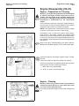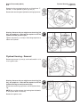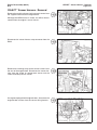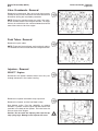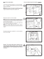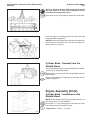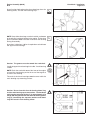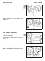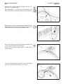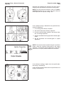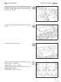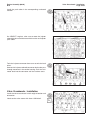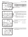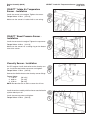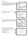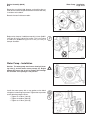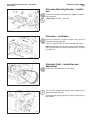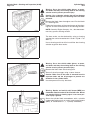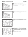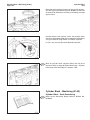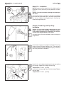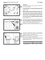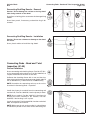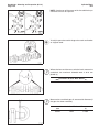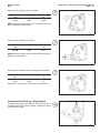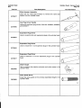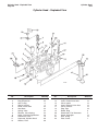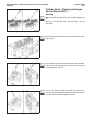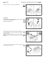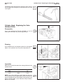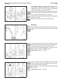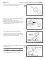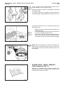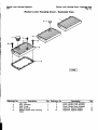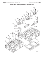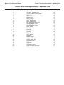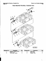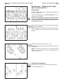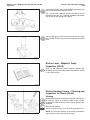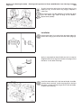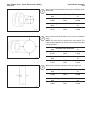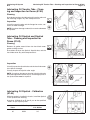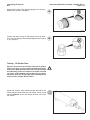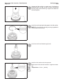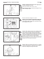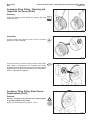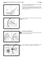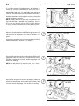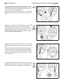
1
Foreword
This manual contains complete rebuild specifications and information for the N14 model engines, and all associated components manufactured by Cummins Engine Company, Inc. A listing of accessory and component
suppliers’ addresses and telephone numbers is located in Section C. Suppliers can be contacted directly for any
information not covered in this manual.
The repair procedures in this manual are based on the engine being installed on an approved engine stand. Some
rebuild procedures require the use of special service tools. Make sure the correct tools are used as described in
the procedures.
When a specific brand name, number, or special tool is referenced in this manual, an equivalent product can be
used in place of the recommended item.
A series of specific service manuals (Troubleshooting and Repair, Specifications, Alternative Repair, and so on.)
are available and can be ordered by filling out and mailing the Literature Order Form located in the Service
Literature Section L.
Reporting of errors, omissions, and recommendations for improving this publication by the user is encouraged.
Please use the postage paid, self-addressed Literature Survey Form in the back of this manual for communicating
your comments.
The specifications and rebuild information in this manual is based on the information in effect at the time of printing.
Cummins Engine Company, Inc. reserves the right to make any changes at any time without obligation. If
differences are found between your engine and the information in this manual, contact a Cummins Authorized
Repair Location, a Cummins Division Office, or the factory.
The latest technology and the highest quality components are used to manufacture Cummins engines. When
replacement parts are needed, we recommend using only genuine Cummins or ReConT exchange parts. These
parts can be identified by the following trademarks:
TABLE OF CONTENTS
Page
Introduction................................................................................................................................................
i-1
Group 0 - Engine Disassembly and Assembly ...........................................................................................
0-1
Group 1 - Cylinder Block...........................................................................................................................
1-1
Group 2 - Cylinder Head ...........................................................................................................................
2-1
Group 3 - Rocker Levers...........................................................................................................................
3-1
Group 4 - Cam Followers ..........................................................................................................................
4-1
Group 5 - Fuel System..............................................................................................................................
5-1
Group 6 - Injectors and Fuel Lines............................................................................................................
6-1
Group 7 - Lubricating Oil System ..............................................................................................................
7-1
Group 8 - Cooling System.........................................................................................................................
8-1
Group 9 - Drive Units ................................................................................................................................
9-1
Group 10 - Air Intake System.................................................................................................................... 10-1
Group 11 - Exhaust System ...................................................................................................................... 11-1
Group 12 - Air Equipment ......................................................................................................................... 12-1
Group 13 - Electrical Equipment ............................................................................................................... 13-1
Group 14 - Engine Testing ........................................................................................................................ 14-1
Group 15 - Instruments and Controls ........................................................................................................ 15-1
Group 16 - Mounting Adaptations ............................................................................................................. 16-1
Group 18 - Specifications............................................................................................................................18-1
Group 20 - Vehicle Braking....................................................................................................................... 20-1
Component Manufacturers: Names and Addresses ......................................................................................C-1
Service Literature .........................................................................................................................................L-1
Index............................................................................................................................................................X-1
Literature Survey Form ..............................................................................................................................back
Cummins 22-Group System Exploded Diagram
Section I - Introduction
N14
Page i-1
Section I - Introduction
Section Contents
Page
Engine Diagrams .............................................................................................................................................. i-13
Engine Identification ........................................................................................................................................ i-12
General Cleaning Instructions..........................................................................................................................
Glass or Plastic Bead Cleaning ......................................................................................................................
Solvent and Acid Cleaning .............................................................................................................................
Steam Cleaning .............................................................................................................................................
i-16
i-16
i-16
i-16
General Repair Instructions ............................................................................................................................... i-3
General Safety Instructions ............................................................................................................................... i-4
Important Safety Notice.................................................................................................................................... i-4
Glossary Of Terms............................................................................................................................................ i-10
Illustrations......................................................................................................................................................... i-9
Manual Organization...........................................................................................................................................
Group Contents................................................................................................................................................
Index ...............................................................................................................................................................
Metric Information ............................................................................................................................................
Table of Contents.............................................................................................................................................
i-2
i-2
i-2
i-2
i-2
Simbolos Usados En Este Manual .................................................................................................................... i-6
Symbole .............................................................................................................................................................. i-8
Symboles Utilises Dans Ce Manuel .................................................................................................................. i-7
Symbols Used in this Manual ........................................................................................................................... i-5
Manual Organization
Page i-2
Section I - Introduction
N14
Manual Organization
All references to engine components in this manual are divided into 22 specific groups. The organization is
consistent with the service bulletins, service parts topics, and the parts catalogs for your convenience in updating
your copy of the shop manual.
Table of Contents
The Table of Contents in the front of the manual contains a quick page reference for each group number.
Group Contents
Each group contains the following information:
• A ‘‘Section Contents’’ page at the beginning of each group to quickly aid in locating the information desired.
• A Service Tools list with recommended tools needed to rebuild the components.
• General information to aid in rebuilding the component and an explanation of design change differences.
• Step-by-step rebuild instructions for disassembly, cleaning, inspection, and assembly of the component.
• Symbols which represent the action outlined in the instructions. The definitions of the symbols, listed in four
languages (English, Spanish, French, and German), appear on pages i-5 through i-8.
Index
An alphabetical index is in the back of the manual to aid in locating specific information.
Metric Information
Both metric and U.S. customary values are used in this manual. The metric value is listed first, followed by the
U.S. customary in brackets. An example is 60°C [140°F].
Section I - Introduction
N14
General Repair Instructions
Page i-3
General Repair Instructions
This engine incorporates the latest diesel technology; yet, it is designed to be repaired using normal repair
practices performed to quality standards.
•
Cummins Engine Company, Inc. does not recommend or authorize any modifications or repairs to
engines or components except for those detailed in Cummins Service Information. In particular, unauthorized repair to safety-related components can cause personal injury. Below is a partial listing of
components classified as safety-related:
Air Compressor
Air Controls
Air Shutoff Assemblies
Balance Weights
Cooling Fan
Fan Hub Assembly
Fan Mounting Bracket(s)
Fan Mounting Capscrews
Fan Hub Spindle
Flywheel
Flywheel Crankshaft Adapter
Flywheel Mounting Capscrews
Fuel Shutoff Assemblies
Fuel Supply Tubes
Lifting Brackets
Throttle Controls
Turbocharger Compressor Casing
Turbocharger Oil Drain Line(s)
Turbocharger Oil Supply Line(s)
Turbocharger Turbine Casing
Vibration Damper Mounting Capscrews
•
Follow All Safety Instructions Noted in the Procedures.
-
•
Provide A Clean Environment and Follow the Cleaning Instructions Specified in the Procedures
-
•
Follow the manufacturer’s recommendations for cleaning solvents and other substances used during the
repair of the engine. Always use good safety practices with tools and equipment.
The engine and its components must be kept clean during any repair. Contamination of the engine and
components will cause premature wear.
Perform the Inspections Specified in the Procedures.
-
The inspections will result in a minimal number of parts requiring replacement. The cost of the rebuild
will be reduced more than the cost of the additional inspection time.
•
Replace all Components or Assemblies Which are Damaged or Worn Beyond the Specifications
•
Use Genuine Cummins New or ReConW Service Parts and Assemblies
-
•
The assembly instructions have been written to reuse as many components and assemblies as possible.
When it is necessary to replace a component or assembly, the procedure is based on the use of new
Cummins or Cummins ReConW components. All of the repair services described in this manual are
available from all Cummins Distributors and most Dealer locations.
Follow The Specified Disassembly and Assembly Procedures to Avoid Damage to the Components.
Complete troubleshooting and repair instructions are available in the Troubleshooting and Repair Manual which
can be ordered or purchased from a Cummins Authorized Repair Location. Refer to Section L, Literature, for
ordering instructions.
General Safety Instructions
Page i-4
Section I - Introduction
N14
General Safety Instructions
Important Safety Notice
WARNING
Read and understand all of the safety precautions and warnings before performing any repair. This list contains
the general safety precautions that must be followed to provide personal safety. Special safety precautions are
included in the procedures when they apply.
• Make sure the work area surrounding the product is safe. Be aware of hazardous conditions that can exist.
• Always wear protective glasses and protective shoes when working.
• Do not wear loose-fitting or torn clothing. Remove all jewelry when working.
• Disconnect the battery and discharge any capacitors before beginning any repair work. Disconnect the air
starting motor if equipped to prevent accidental engine starting. Put a ″Do Not Operate″ tag in the operator’s
compartment or on the controls.
• Use ONLY the proper engine barring techniques for manually rotating the engine. Do not attempt to rotate
the engine by pulling or prying on the fan. This practice can cause serious personal injury, property damage,
or damage to the fan blade(s) causing premature fan failure.
• If an engine has been operating and the coolant is hot, allow the engine to cool before you slowly loosen the
filler cap and relieve the pressure from the cooling system.
• Do not work on anything that is supported ONLY by lifting jacks or a hoist. Always use blocks or proper stands
to support the product before performing any service work.
• Relieve all pressure in the air, oil, and the cooling systems before any lines, fittings, or related items are
removed or disconnected. Be alert for possible pressure when disconnecting any device from a system that
utilizes pressure. Do not check for pressure leaks with your hand. High pressure oil or fuel can cause personal
injury.
• To prevent suffocation and frostbite, wear protective clothing and ONLY disconnect liquid refrigerant (freon)
lines in a well ventilated area.
• To avoid personal injury, use a hoist or get assistance when lifting components that weigh 23 kg [50 lb] or
more. Make sure all lifting devices such as chains, hooks, or slings are in good condition and are of the correct
capacity. Make sure hooks are positioned correctly. Always use a spreader bar when necessary. The lifting
hooks must not be side-loaded.
• Cooling System corrosion inhibitor contains alkali. Do not get the substance in your eyes. Avoid prolonged
or repeated contact with skin. Do not swallow internally. In case of contact, immediately wash skin with soap
and water. In case of contact, immediately flood eyes with large amounts of water for a minimum of 15 minutes.
IMMEDIATELY CALL A PHYSICIAN. KEEP OUT OF REACH OF CHILDREN.
• Naptha and Methyl Ethyl Ketone (MEK) are flammable materials and must be used with caution. Follow the
manufacturer’s instructions to provide complete safety when using these materials. KEEP OUT OF REACH
OF CHILDREN.
• To avoid burns, be alert for hot parts on products that have just been turned OFF, and hot fluids in lines, tubes,
and compartments.
• Always use tools that are in good condition. Make sure you understand how to use them before performing
any service work. Use ONLY genuine Cummins or Cummins ReconW replacement parts.
• Always use the same fastener part number (or equivalent) when replacing fasteners. Do not use a fastener
of lessor quality if replacements are necessary.
Section I - Introduction
N14
Symbols Used in this Manual
Page i-5
Symbols Used in this Manual
The following group of symbols has been used in this manual to help communicate the intent of the instructions.
When one of the symbols appears, it conveys the meaning defined below.
WARNING - Serious personal injury or extensive property damage can result if the warning
instructions are not followed.
CAUTION - Minor personal injury can result or a part, an assembly or the engine can be damaged
if the caution instructions are not followed.
Indicates a REMOVAL or DISASSEMBLY step.
Indicates an INSTALLATION or ASSEMBLY step.
INSPECTION is required.
CLEAN the part or assembly.
PERFORM a mechanical or time MEASUREMENT.
LUBRICATE the part or assembly.
Indicates that a WRENCH or TOOL SIZE will be given.
TIGHTEN to a specific torque.
PERFORM an electrical MEASUREMENT.
Refer to another location in this manual or another publication for additional information.
The component weighs 23 kg [50 lb] or more. To avoid personal injury, use a hoist or get
assistance to lift the component.
Simbolos Usados En Este Manual
Page i-6
Section I - Introduction
N14
Simbolos Usados En Este Manual
Los si´mbolos siguientes son usados en este manual para clarificar el proceso de las instrucciones. Cuando
aparece uno de estos si´mbolos, su significado se especifica en la parte inferior.
ADVERTENCIA - Serios dan˜os personales o dan˜o a la propiedad puede resultar si las instrucciones
de Advertencia no se consideran.
PRECAUCION - Dan˜os menores pueden resultar, o de piezas del conjunto o el motor puede
averiarse si las instrucciones de Precaucio´n no se siguen.
Indica un paso de REMOCION o DESMONTAJE.
Indica un paso de INSTALACION o MONTAJE.
Se requiere INSPECCION.
LIMPIESE la pieza o el montaje.
EJECUTESE una MEDICION meca´nica o del tiempo.
LUBRIQUESE la pieza o el montaje.
Indica que se dara´ una LLAVE DE TUERCAS o el TAMAN
x O DE HERRAMIENTA.
APRIETESE hasta un par torsor especi´fico.
EJECUTESE una MEDICION ele´ctrica.
Para informacio´n adicional refie´rase a otro emplazamiento de este manual o a otra publicacio´n
anterior.
El componente pesa 23 kg [50 lb] o mas. Para evitar dano corporal empleen una cabria u obtengan
ayuda para elevar el componente.
Section I - Introduction
N14
Symboles Utilises Dans Ce Manuel
Page i-7
Symboles Utilises Dans Ce Manuel
Les symboles suivants sont utilise´s dans ce manuel pour aider a` communiquer le but des instructions. Quand l’un
de ces symboles apparaiˆt, il e´voque le sens de´fini ci-dessous:
AVERTISSEMENT - De graves le´sions corporelles ou des dommages mate´riels conside´rables
peuvent survenir si les instructions donne´es sous les rubriques ″Avertissement″ ne sont pas
suivies.
ATTENTION - De petites le´sions corporelles peuvent survenir, ou bien une pie`ce, un ensemble
ou le moteur peuvent eˆtre endommage´s si les instructions donne´es sous les rubriques ″Attention″ ne sont pas suivies.
Indique une ope´ration de DEPOSE.
Indique une ope´ration de MONTAGE.
L’INSPECTION est ne´cessaire.
NETTOYER la pie`ce ou l’ensemble.
EFFECTUER une MESURE me´canique ou de temps.
GRAISSER la pie`ce ou l’ensemble.
Indique qu’une DIMENSION DE CLE ou D’OUTIL sera donne´e.
SERRER a` un couple spe´cifique.
EFFECTUER une MESURE e´lectrique.
Se reporter a` un autre endroit dans ce manuel ou a` une autre publication pour obtenir des
informations plus comple`tes.
Le composant pese 23 kg [50 lb] ou davantage. Pour eviter toute blessure, employer un appariel
de levage ou demander de l’aide pour le soulever.
Symbole
Page i-8
Section I - Introduction
N14
Symbole
In diesem Handbuch werden die folgenden Symbole verwendet, die wesentliche Funktionen hervorheben. Die
Symbole haben folgende Bedeutung:
WARNUNG - Wird die Warnung nicht beachtet, dann besteht erho¨hte Unfall- und
Bescha¨digungsgefahr.
VORSICHT - Werden die Vorsichtsmassnahmen nicht beachtet, dann besteht Unfall- und
Bescha¨digungsgefahr.
AUSBAU bzw. ZERLEGEN.
EINBAU bzw. ZUSAMMENBAU.
INSPEKTION erforderlich.
Teil oder Baugruppe REINIGEN.
DIMENSION - oder ZEITMESSUNG.
Teil oder Baugruppe O
} LEN.
WERKZEUGGRO
} SSE wird angegeben.
ANZUG auf vorgeschriebenes Drehmoment erforderlich.
Elektrische MESSUNG DURCHFU
} HREN.
Weitere Informationen an anderer Stelle bzw. in anderen Handbu¨chern.
Das teil weigt 23 kg [50 lb] oder mehr. Zur vermeidung von koerperverletzung winde benutzen
oder hilfe beim heben des teils in anspruch nehmen.
Section I - Introduction
N14
Illustrations
Page i-9
Illustrations
The illustrations used in this manual are intended to give an example of how to perform the action or the repair
being described. Many of the illustrations are common and will not look exactly like the engine or the parts used
in your application. Most of the illustrations contain symbols to indicate an action required or to indicate an
acceptable (OK) or unacceptable (not OK) condition.
Glossary Of Terms
Page i-10
Section I - Introduction
N14
Glossary Of Terms
AFC:
Air Fuel Control; a device in the PT fuel pump that limits the fuel delivery until
there is sufficient intake manifold pressure to allow for complete combustion.
ATDC:
After Top Dead Center; refers to the position of the piston or the crankshaft
rod journal. The piston is moving downward on the power stroke and intake
stroke.
BDC:
Bottom Dead Center; refers to the position of the piston or the crankshaft rod
journal. The piston is at its lowest position in the cylinder.
BTDC:
Before Top Dead Center; refers to the position of the piston or the crankshaft
rod journal. The piston is moving upward on the compression stroke and exhaust stroke.
Circumferential Direction:
In the direction of a circle in respect to the centerline of a round part or a
bore.
Concentricity:
A measurement of the difference between the centers of either two or more
parts or the bores in one part.
CPL:
Control Parts List; this listing identifies the specific parts that must be installed on the engine to meet agency certification.
Cummins Sealant:
This is a one part Room Temperature Vulcanizing (RTV) silicone rubber, adhesive and sealant material having high heat and oil resistance, and low compression set.
Some of the equivalent products are Marston Lubricants, Hylosil, Dow Corning, Silastic 732, Loctite Superflex, General Electric 1473, and General Electric 1470.
D.C.:
Direct Current
Dye Penetrant Method:
A method used to check for cracks in a part by using a dye penetrant and a
developer. Use crack detection kit, Part No. 3375432, or its equivalent.
End Clearance:
The clearance in an assembly determined by pushing the shaft in an axial direction one way and then pushing the shaft the other way.
E.S.N.:
Engine Serial Number
Hammer:
A hand tool consisting of a hard steel head on a handle.
I.D.:
Inside Diameter
Loctite 290:
A single component, anaerobic, polyester resin, liquid sealant compound that
hardens between closely fitted metal surfaces producing a tough, hard bond
with good characteristics. An equivalent product is Perma-Lok HL 126.
Loctite 609:
A single component anaerobic, liquid adhesive that meets or exceeds the requirements of MIL-R-46082A (MR) TYPE 1.
Some of the equivalent products are Loctite 601 and Permabond HL 138.
Lubriplate 105:
A mineral oil base grease with calcium soap (2 percent to 6 percent), and zinc
oxide (2 percent to 4 percent) additives.
Section I - Introduction
N14
Glossary Of Terms
Page i-11
Magnetic Particle Inspection:
A method of checking for cracks in either steel or iron parts. This method requires a Magnaflux machine, or an equivalent machine that imparts a magnetic field on the part being checked.
Mallet:
A hand tool consisting of a soft head, either wood, plastic, lead, brass, or
rawhide, on a handle.
MAX:
Maximum allowed
MIN:
Minimum allowed
No.:
Number
O.D.:
Outside Diameter
OS:
Oversize
Protrusion:
The difference in the height between two parts in the assembled state.
STD:
Standard
TDC:
Top Dead Center; refers to the position of the piston or the crankshaft rod
journal. The piston is at its highest position in the cylinder. The rod journal is
pointing straight up toward the piston.
T.I.R.:
Total Indicator Runout; used when measuring the concentricity or the runout.
The T.I.R. refers to the total movement of the needle on a dial indicator, from
the most negative reading to the most positive reading.
Water Pump Grease:
A premium high temperature grease that will lubricate antifriction bearings
continually from minus 40°C [minus 40°F] to plus 150°C [plus 350°F].
Some of the greases meeting this requirement are Aeroshell No. 5, Chevron
SRI, Amoco Rykon Premium No. 2, Texaco Premium RB, and Shell Dolium R.
Aeroshell No. 5 is not compatible with the other greases and must not be
mixed. Cummins Engine Company, Inc., uses Aeroshell No. 5 on new engines
and components.
Engine Identification
Page i-12
Section I - Introduction
N14
Engine Identification
The engine dataplate provides the model identification
and other important information about the engine.
Have the following engine data available when communicating with a Cummins Authorized Repair Location.
The information on the dataplate is mandatory when
sourcing service parts:
1. Engine Serial Number (E.S.N.)
2. Control Parts List (CPL)
3. Model
4. Advertised Horsepower and RPM
ap8plgi
The model name provides the following engine data:
N
14
330
E
CELECT™ Identification
Advertised Horsepower
Displacement (Liters)
Engine Model Designation
Section I - Introduction
N14
Engine Diagrams
Page i-13
Engine Diagrams
The following drawings contain information about engine components, filter locations, drain points, and access
locations for instrumentation and engine controls.
The information and configuration of components shown in these drawings are of a general nature. Some
component locations will vary depending on applications and installations.
Engine Diagrams
Page i-14
Section I - Introduction
N14
Section I - Introduction
N14
Engine Diagrams
Page i-15
General Cleaning Instructions
Page i-16
Section I - Introduction
N14
General Cleaning Instructions
Solvent and Acid Cleaning
Several solvent and acid-type cleaners can be used to clean the engine parts. Cummins Engine Company,
Inc. does not recommend any specific cleaners. Always follow the cleaner manufacturer’s instructions.
Experience has shown that the best results can be obtained using a cleaner that can be heated to 90 to
95 degrees Celsius [180 to 200 degrees Fahrenheit]. A cleaning tank that provides a constant mixing and
filtering of the cleaning solution will give the best results.
Remove all the gasket material, o-rings, and the deposits of sludge, carbon, etc., with a wire brush or scraper
before putting the parts in a cleaning tank. Be careful not to damage any gasket surfaces. When possible,
steam clean the parts before putting them in the cleaning tank.
Warning: The use of acid can be extremely dangerous to personnel, and can damage the machinery.
Always provide a tank of strong soda water as a neutralizing agent.
Rinse all of the parts in hot water after cleaning. Dry completely with compressed air. Blow the rinse water from
all of the capscrew holes and the oil drillings.
If the parts are not to be used immediately after cleaning, dip them in a suitable rustproofing compound. The
rustproofing compound must be removed from the parts before installation on the engine.
Steam Cleaning
Steam cleaning can be used to remove all types of dirt that can contaminate the cleaning tank. It is the
recommended way to clean the oil drillings.
Warning: Wear protective clothing to prevent personal injury from the high pressure and extreme heat.
Do not steam clean the following parts:
1. Electrical Components
2. Wiring
3. Injectors
4. Fuel Pump
5. Belts and Hoses
6. Bearings
Glass or Plastic Bead Cleaning
Glass or plastic bead cleaning can be used on many engine components to remove carbon deposits. The
cleaning process is controlled by the size of the glass or plastic beads, the operating pressure, and the
cleaning time.
Caution: Do not use glass or plastic bead cleaning on aluminum piston skirts. Do not use glass bead
cleaning on aluminum ring grooves. Small particles of glass or plastic will embed in the aluminum and
result in premature wear. Valves, turbocharger shafts, etc., can also be damaged. Follow the cleaning
directions listed in the procedures.
NOTE: Plastic bead blasting media, Part No. 3822735, can be used to clean aluminum ring grooves. Do not use
any bead blasting media on pin bores or aluminum skirts.
Follow the equipment manufacturer’s cleaning instructions. The following guidelines can be used to adapt to
manufacturer’s instructions:
1.
Bead size: -
Use U.S. size No. 16-20 for piston cleaning with plastic bead media, Part No. 3822735.
Use U.S. size No. 70 for piston domes with glass media.
Use U.S. size No. 60 for general purpose cleaning with glass media.
2.
Operating Pressure:
3.
Steam clean or wash the parts with solvent to remove all of the foreign material and glass or plastic
beads after cleaning. Rinse with hot water. Dry with compressed air.
4.
Do not contaminate the wash tanks with glass or plastic beads.
- Glass: Use 620 kPa [90 psi] for general purpose cleaning.
- Plastic: Use 270 kPa [40 psi] for piston cleaning.
Engine Disassembly and Assembly
N14
Page 0-1
Section 0 - Engine Disassembly and Assembly - Group 00
Section Contents
Page
Accessory Drive - Installation ........................................................................................................................ 0-89
Accessory Drive - Removal ............................................................................................................................ 0-31
Accessory Drive Pulley - Installation .............................................................................................................. 0-97
Accessory Drive Pulley - Removal ................................................................................................................. 0-23
Accessory Drive Seal - Installation ................................................................................................................ 0-96
Accessory Drive Seal - Removal ..................................................................................................................... 0-39
Air Compressor - Installation ........................................................................................................................ 0-124
Air Compressor - Removal .............................................................................................................................. 0-30
Air Compressor Coolant Inlet and Outlet Tubes - Installation ..................................................................... 0-135
Air Compressor Coolant Inlet and Outlet Tubes - Removal .......................................................................... 0-22
Alternator - Installation.................................................................................................................................. 0-142
Alternator - Removal ...................................................................................................................................... 0-14
Alternator Belts - Installation and Adjustment ............................................................................................. 0-142
Alternator Belts - Removal ............................................................................................................................. 0-13
Alternator Mounting Bracket - Installation.................................................................................................... 0-142
Alternator Mounting Bracket - Removal ........................................................................................................ 0-14
Cam Follower Assemblies - Installation ........................................................................................................ 0-80
Cam Follower Assemblies - Removal ............................................................................................................ 0-38
Camshaft - Installation ................................................................................................................................... 0-78
Camshaft - Removal ....................................................................................................................................... 0-39
Camshaft Bearing Support - Installation ....................................................................................................... 0-94
Camshaft Bearing Support - Removal ........................................................................................................... 0-38
CELECT™ Actuator Harness - Installation ..................................................................................................... 0-128
CELECT™ Actuator Harness - Removal .......................................................................................................... 0-25
CELECT™ Ambient Air Pressure Sensor - Installation.................................................................................. 0-126
CELECT™ Ambient Air Pressure Sensor - Removal ...................................................................................... 0-28
CELECT™ Boost Pressure Sensor - Installation............................................................................................ 0-121
CELECT™ Boost Pressure Sensor - Removal ................................................................................................ 0-33
CELECT™ Coolant Temperature Sensor - Installation .................................................................................. 0-135
CELECT™ Coolant Temperature Sensor - Removal ....................................................................................... 0-21
CELECT™ ECM Cooling Plate - Installation ................................................................................................... 0-125
CELECT™ ECM Cooling Plate - Removal ........................................................................................................ 0-29
CELECT™ Electronic Control Module (ECM) - Installation ............................................................................ 0-126
CELECT™ Electronic Control Module (ECM) - Removal ................................................................................. 0-28
CELECT™ Engine Position Sensor (EPS) - Installation ................................................................................... 0-91
CELECT™ Engine Position Sensor (EPS) - Removal ...................................................................................... 0-31
CELECT™ Intake Air Temperature Sensor - Installation ............................................................................... 0-121
CELECT™ Intake Air Temperature Sensor - Removal .................................................................................... 0-33
CELECT™ Lubricating Oil Pressure Sensor - Installation ............................................................................. 0-126
Page 0-2
Engine Disassembly and Assembly
N14
Page
CELECT™ Lubricating Oil Pressure Sensor - Removal .................................................................................. 0-29
CELECT™ Sensor Harness - Installation........................................................................................................ 0-127
CELECT™ Sensor Harness - Removal ............................................................................................................ 0-27
Coolant - Drainage........................................................................................................................................... 0-11
Coolant Filter - Installation............................................................................................................................ 0-147
Coolant Filter - Removal ................................................................................................................................ 0-11
Coolant Inlet Transfer Connection - Installation........................................................................................... 0-140
Coolant Inlet Transfer Connection - Removal ............................................................................................... 0-15
Crankcase Breather - Removal ...................................................................................................................... 0-12
Crankcase Breather Tube - Installation ........................................................................................................ 0-147
Crankshaft - Installation ................................................................................................................................. 0-48
Crankshaft - Removal ..................................................................................................................................... 0-44
Crankshaft Seal, Front - Installation .............................................................................................................. 0-94
Crankshaft Seal, Front - Removal ................................................................................................................... 0-39
Crankshaft Seal, Rear - Installation ............................................................................................................... 0-66
Crankshaft Seal, Rear - Removal ................................................................................................................... 0-20
Cylinder Block - Installation on the Rebuild Stand ....................................................................................... 0-46
Cylinder Block - Removal from the Rebuild Stand ........................................................................................ 0-46
Cylinder Heads - Installation .......................................................................................................................... 0-76
Cylinder Heads - Removal .............................................................................................................................. 0-37
Cylinder Liners - Installation .......................................................................................................................... 0-57
Cylinder Liners - Removal .............................................................................................................................. 0-42
Dipstick Tube and Housing - Installation...................................................................................................... 0-140
Dipstick Tube and Housing - Removal .......................................................................................................... 0-15
Engine - Cleaning ........................................................................................................................................... 0-10
Engine - Covering All Openings.................................................................................................................... 0-148
Engine - Installation on the Rebuild Stand .................................................................................................... 0-16
Engine - Preparation for Cleaning................................................................................................................... 0-10
Engine - Removal From the Rebuild Stand................................................................................................... 0-138
Engine Brake - Adjustment ...........................................................................................................................
C-Brake.......................................................................................................................................................
C-Brake - Alternate Method .........................................................................................................................
Jacobs Brake ..............................................................................................................................................
0-115
0-115
0-118
0-119
Engine Brake - Installation ............................................................................................................................ 0-115
Engine Brakes - Removal ............................................................................................................................... 0-34
Engine Disassembly and Assembly - General information .............................................................................. 0-9
Assembly ........................................................................................................................................................ 0-9
Disassembly ................................................................................................................................................... 0-9
Engine Disassembly and Assembly - Service Tools ........................................................................................ 0-5
Engine Support Bracket, Front - Installation ................................................................................................ 0-131
Engine Support Bracket, Front - Removal ..................................................................................................... 0-23
Exhaust Manifold - Installation...................................................................................................................... 0-144
Exhaust Manifold - Removal ........................................................................................................................... 0-13
Fan and Fan Spacer - Installation ................................................................................................................. 0-143
Engine Disassembly and Assembly
N14
Page 0-3
Page
Fan and Fan Spacer - Removal ...................................................................................................................... 0-13
Fan Belts - Installation and Adjustment........................................................................................................ 0-137
Fan Belts - Removal ....................................................................................................................................... 0-20
Fan Hub and Fan Hub Support Bracket - Installation................................................................................... 0-136
Fan Hub and Fan Hub Support Bracket - Removal ....................................................................................... 0-21
Flywheel - Installation .................................................................................................................................... 0-72
Bore Alignment - Measurement .................................................................................................................... 0-73
Face Alignment - Measurement .................................................................................................................... 0-75
Flywheel - Removal ........................................................................................................................................ 0-18
Flywheel Housing - Installation ...................................................................................................................... 0-67
Bore Alignment - Measurement .................................................................................................................... 0-68
Face Alignment - Measurement .................................................................................................................... 0-70
Flywheel Housing - Removal ......................................................................................................................... 0-19
Fuel Crossovers - Installation ........................................................................................................................ 0-98
Fuel Crossovers - Removal ............................................................................................................................ 0-37
Fuel Pump - Installation ................................................................................................................................ 0-124
CELECT™ Engines ...................................................................................................................................... 0-124
STC Engines............................................................................................................................................... 0-125
Fuel Pump - Removal ..................................................................................................................................... 0-29
CELECT™ Engines ....................................................................................................................................... 0-29
STC Engines ................................................................................................................................................ 0-30
Fuel Tubing - Installation .............................................................................................................................. 0-123
Fuel Tubing - Removal ................................................................................................................................... 0-31
Gear Cover - Installation ................................................................................................................................ 0-92
Gear Cover - Removal .................................................................................................................................... 0-39
Injection Timing - General Information .......................................................................................................... 0-80
Timing Tool Installation ................................................................................................................................ 0-82
Injector and Valve Adjustment...................................................................................................................... 0-105
CELECT™ Engines ...................................................................................................................................... 0-105
STC Engines............................................................................................................................................... 0-109
Injectors - Installation ................................................................................................................................... 0-100
CELECT™ Engines ..................................................................................................................................... 0-100
STC Engines............................................................................................................................................... 0-101
Injectors - Removal ........................................................................................................................................ 0-35
CELECT™ Engines ....................................................................................................................................... 0-35
STC Engines ................................................................................................................................................ 0-36
Intake Manifold - Installation ......................................................................................................................... 0-120
Intake Manifold - Removal ............................................................................................................................. 0-33
Lubricating Oil Cooler Assembly - Installation ............................................................................................. 0-141
Lubricating Oil Cooler Assembly - Removal .................................................................................................. 0-14
Lubricating Oil Filter - Installation ................................................................................................................ 0-147
Lubricating Oil Filter - Removal ..................................................................................................................... 0-11
Lubricating Oil Pan - Installation ................................................................................................................... 0-98
Lubricating Oil Pan - Removal ....................................................................................................................... 0-39
Lubricating Oil Pump - Installation ................................................................................................................ 0-91
Lubricating Oil Pump - Removal ..................................................................................................................... 0-32
Lubricating Oil Pump Signal Line - Installation ............................................................................................ 0-122
Lubricating Oil Pump Signal Line - Removal.................................................................................................. 0-32
Page 0-4
Engine Disassembly and Assembly
N14
Page
Lubricating Oil Transfer Tube - Installation.................................................................................................. 0-122
Lubricating Oil Transfer Tube - Removal ...................................................................................................... 0-31
Piston and Connecting Rod Assemblies - Assembly and Installation .......................................................... 0-61
Piston and Connecting Rod Assemblies - Removal ....................................................................................... 0-40
Piston Cooling Nozzles - Installation ............................................................................................................ 0-139
Piston Cooling Nozzles - Removal ................................................................................................................. 0-15
Push Tubes - Installation ............................................................................................................................. 0-102
Push Tubes - Removal ................................................................................................................................... 0-35
Rear Cover - Installation ................................................................................................................................ 0-65
Rear Cover - Removal .................................................................................................................................... 0-20
Rocker Housing Covers - Installation ........................................................................................................... 0-119
Rocker Housing Covers - Removal ................................................................................................................ 0-34
Rocker Lever Housing - Installation .............................................................................................................. 0-98
Rocker Lever Housing - Removal .................................................................................................................. 0-36
Rocker Lever Shaft Assemblies - Installation .............................................................................................. 0-104
Rocker Lever Shaft Assemblies - Removal ................................................................................................... 0-34
Starting Motor - Installation .......................................................................................................................... 0-144
Starting Motor - Removal ............................................................................................................................... 0-13
STC External Oil Plumbing - Installation ...................................................................................................... 0-130
STC External Oil Plumbing - Removal ........................................................................................................... 0-24
STC Oil Control Valve - Installation .............................................................................................................. 0-129
STC Oil Control Valve - Removal ................................................................................................................... 0-25
Thermostat Housing - Installation................................................................................................................. 0-135
Thermostat Housing - Removal ..................................................................................................................... 0-22
Turbocharger - Installation............................................................................................................................ 0-145
Turbocharger - Removal ................................................................................................................................ 0-12
Valve Crossheads - Installation .................................................................................................................... 0-103
Valve Crossheads - Removal ......................................................................................................................... 0-35
Vibration Damper - Installation ..................................................................................................................... 0-131
Vibration Damper - Removal .......................................................................................................................... 0-23
Viscosity Sensor - Installation ...................................................................................................................... 0-121
Viscosity Sensor - Removal ........................................................................................................................... 0-32
Water Header Covers - Installation ............................................................................................................... 0-140
Water Header Covers - Removal .................................................................................................................... 0-16
Water Pump - Installation.............................................................................................................................. 0-133
Water Pump - Removal .................................................................................................................................. 0-23
Water Pump Belt - Installation and Adjustment ........................................................................................... 0-134
Water Pump Belt - Removal ........................................................................................................................... 0-21
Engine Disassembly and Assembly
N14
Engine Disassembly and Assembly - Service Tools
Page 0-5
Engine Disassembly and Assembly - Service Tools
The following special tools are recommended to perform procedures in section 1. The use of these
tools is shown in the appropriate procedure. These tools can be purchased from your local Cummins
Authorized Repair Location.
Tool No.
Tool Description
Lifting Fixture
ST-125 or
3822512
Designed to lift all H/NH engines except 5 1/8-inch bore with a
top mounted turbocharger.
Engine Support Stand
ST-163
Support engine when not in-chassis or on the engine rebuild
stand.
Standard Puller
Use to remove drive pulleys, impellers, etc.
ST-647
Torque Wrench Adapter
Tighten crosshead and rocker lever adjusting screws.
ST-669
Crankshaft Oil Seal Installer
ST-997
Use to drive the crankshaft oil seal into the rear cover. This tool
also aligns the rear cover to the crankshaft.
Fuel Pump Drive Oil Seal Mandrel
ST-1173
Use to drive the accessory drive oil seal into the gear cover while
mounted.
Tool Illustration
Engine Disassembly and Assembly - Service Tools
Page 0-6
Tool No.
Engine Disassembly and Assembly
N14
Tool Description
Main Bearing Cap Puller
Remove main bearings caps.
ST-1178
Top Plate
ST-1259-1
Included in oil seal puller/installer, Part No. ST-1259. Use to pull
or install the front crankshaft oil seal.
Belt Tension Gauge
Measure drive belt tension.
ST-1293
Dial Gauge Attachment
ST-1325
Attaches to crankshaft to provide measuring of flywheel housing
runout with a dial indicator.
Adapter Plate
3375013
Use the adapter plate to mount the engine to engine rebuild
stand, Part No. 3375194.
Oil Filter Wrench
Use to remove or tighten spin-on lubricating oil filters.
3375049
Engine Rebuild Stand
3375194
Support cylinder block during engine rebuild. Use with adapter
plate, Part No. 3375013.
Camshaft Installation Pilots
3375268
Use to guide the camshaft though the block camshaft bushings.
Four are required per operation.
Tool Illustration
Engine Disassembly and Assembly
N14
Tool No.
Engine Disassembly and Assembly - Service Tools
Page 0-7
Tool Description
Connecting Rod Guide Pins
3375601
Guide connecting rods over crankshaft during removal or installation of connecting rods.
Nylon Lifting Sling
3375957
Aid in removal and installation of crankshaft, flywheel, and other
heavy components.
Dial Indicator and Sleeve Assembly
3376050
Use with dial gauge attachment, Part No. ST-1325, to measure
flywheel and flywheel housing runout.
Pulley Installation Tool
Install drive pulleys.
3376326
Inch Pound Torque Wrench
3376592
Required to make consistent settings of the top stop injectors.
Screwdriver socket, Part No. ST-669-13, must be used with this
tool.
Water and Fuel Filter Wrench
Use to remove the coolant filter and the fuel filter.
3376807
Lubrication Suction Tube O-ring Expander
Use to install the lubricating oil transfer tube.
3376844
Belt Tension Gauge
3822524
Use to check the belt tension on 3/8-inch to 1/2-inch top width
belts.
Tool Illustration
Engine Disassembly and Assembly
N14
Engine Disassembly and Assembly - General information
Page 0-9
Engine Disassembly and Assembly - General information
These procedures apply to all N14 engines. The differences between engine models due to the application, the
optional equipment on an engine, and the year an engine was built are included in the instructions. Omit the steps
that do not apply to the engine being rebuilt.
1. A warning statement is included for any component or assembly that weighs more than 23 kg [50 lb]. To avoid
personal injury, use a hoist or get assistance from more than one person when removing or installing these
parts.
2. All capscrews used on the N14 engine are U.S. customary.
Disassembly
The instructions in this procedure are organized in a logical sequence to disassemble an engine. This is not the
only sequence to disassemble an engine. Certain parts must be removed in the sequence indicated. Use this
sequence until you become familiar with the engine.
Discard all gaskets (except rocker housing cover gaskets which are reusable), seals, hoses, filters, and o-rings.
Keep these parts if they are needed for a failure analysis.
Label, tag, or mark the parts for location as the parts are removed in order to easily find all of the parts that can
be involved in a failure and to simplify the assembly procedure.
Label, tag, mark or photograph all special equipment prior to the removal from an engine. This engine assembly
procedure does not include the installation of special optional equipment.
Force must be used to remove certain parts. A mallet must be used when force is required. All of the fasteners
must be removed before using force.
Avoid as much dirt as possible during disassembly. The accumulation of additional dirt will make it more difficult
to clean the components.
Assembly
Make sure all the components and assemblies have been cleaned, replaced or rebuilt, and are ready to be installed
on the engine before beginning the assembly process.
Torque values are listed in each step. If a torque value is not specified, use the chart listed in Specifications, Group
18, to determine the correct torque value.
Many of the gaskets and the o-rings are manufactured from a material designed to absorb oil. These gaskets will
enlarge and provide a tight seal after coming in contact with oil. Use ONLY a recommended contact adhesive or
a vegetable-based oil to install these parts.
Always use a capscrew of the same system (metric or U.S. customary), the same dimension, and the same grade
as the capscrew removed. The use of a longer, shorter, different grade, or wrong thread capscrew than the
capscrew that is listed can result in damage to the engine.
Engine - Preparation for Cleaning
Page 0-10
Engine Disassembly (00-01)
N14
Engine Disassembly (00-01)
Engine - Preparation for Cleaning
Warning: The engine lifting equipment must be designed
to safely lift the engine and the transmission as an assembly. The dry weight of the standard engine with
accessories is 1256 kg [2770 lbs]. Refer to the equipment
manufacturer’s specifications for the transmission
weight.
Use a correctly rated hoist, and attach engine lifting fixture, Part No. ST-125 or Part No. 3822512, to the engine
mounted lifting brackets to remove the engine.
NOTE: If the transmission is not removed, place a support
under the transmission to prevent it from falling.
Installations such as short and medium nose conventional chassis, the factory installed rear engine lifting
brackets are usually removed due to space constraints.
In this case, the service rear engine lifting bracket, Part
No. 3823835, will be required to remove the engine from
the chassis.
Refer to the N14 Troubleshooting and Repair Manual,
Bulletin No. 3810456, Section 9, for further information.
Install the engine on two engine support stands, Part No.
ST-163.
Label and remove all electrical wiring and controls.
Install caps or tape on the following openings to prevent
moisture and dirt from entering the engine:
1. Both sides of the turbocharger.
2. All oil, air, water, and fuel openings.
Engine - Cleaning
Warning: When using a steam cleaner, wear protective
clothing and safety glasses or a face shield. Hot steam
can cause serious personal injury.
Use steam to clean the engine, and dry with compressed
air.
Engine Disassembly (00-01)
N14
NOTE: The maximum oil pan capacity is 34 liters [9.0 U.S.
gallons].
Remove the drain plug and the copper washer. Check the
copper washer for wear.
Drain the oil.
If the drain plug is installed again, tighten the plug to the
specified torque.
Torque Value: 136 N•m
[100 ft-lb]
Coolant - Drainage
Remove the plugs from the engine and open the cylinder
block draincock and the oil cooler draincock.
Use a suitable container to catch the coolant as it is
drained.
Coolant Filter - Removal
Use a water and fuel filter wrench, Part No. 3376807, to
remove the coolant filter.
Lubricating Oil Filter - Removal
Use an oil filter wrench, Part No. 3375049, to remove the
lubricating oil filter.
Coolant - Drainage
Page 0-11
Crankcase Breather - Removal
Page 0-12
Engine Disassembly (00-01)
N14
Crankcase Breather - Removal
Loosen the hose clamp at the breather vent tube.
Remove the tube support bracket capscrew and the
bracket.
Remove the tube and the hose from the engine.
Turbocharger - Removal
Remove the oil supply and the oil drain tubes from the
turbocharger.
Remove the four turbocharger mounting nuts.
Remove the turbocharger and discard the gasket.
NOTE: If the turbocharger mounting nuts do not loosen
freely, split the nuts to avoid breaking a mounting stud.
Loosen the clamp on the discharge elbow.
Remove the elbow and discard the o-ring.
Engine Disassembly (00-01)
N14
Exhaust Manifold - Removal
NOTE: Two dowels are used in each cylinder head to align
the exhaust manifold assembly.
Remove two capscrews, and install two guide studs.
Warning: Because this assembly weighs more than 23
kg [50 lbs], two people or a hoist will be required to lift
the exhaust manifold assembly to avoid personal injury.
Remove the remaining ten capscrews, the exhaust manifold assembly, and the manifold gaskets.
Starting Motor - Removal
Warning: Because this part weighs more than 23 kg [50
lbs], two people or a hoist will be required to lift the
starting motor to avoid personal injury.
Remove the three starting motor capscrews, the starting
motor, and the spacer (if used).
Fan and Fan Spacer - Removal
Caution: A fan hub spacer can be behind the fan. It will
drop as the fan is removed. Make sure to remove the fan
and the fan hub spacer together.
Remove the six capscrews and the fan.
NOTE: Do not discard the fan spacers. The spacers provide
the thickness needed to install the fan in the correct position.
Alternator Belts - Removal
Loosen the alternator to alternator support nut and capscrew.
Loosen the adjusting link capscrew and tensioning bolt,
if applicable.
Push the alternator toward the engine to release tension
on the alternator belt, and remove the belt(s).
Exhaust Manifold - Removal
Page 0-13
Alternator - Removal
Page 0-14
Engine Disassembly (00-01)
N14
Alternator - Removal
Remove the adjusting link capscrew and the adjusting
link.
Remove the alternator to alternator support bracket, nut,
washer, capscrew, and the alternator.
Alternator Mounting Bracket - Removal
Remove the three alternator mounting bracket capscrews
and the mounting bracket.
Lubricating Oil Cooler Assembly Removal
Remove the capscrew which holds the oil cooler support
bracket to the cylinder block at the rear of the oil cooler.
Remove one of the capscrews which holds the oil cooler
support to the cylinder block. Install a guide stud in the
hole.
Engine Disassembly (00-01)
N14
Warning: Because this part weighs more than 23 kg [50
lbs], two people or a hoist will be required to lift the oil
cooler assembly to avoid personal injury.
Remove the remaining five capscrews from the oil cooler
support, and remove the cooler assembly.
Coolant Inlet Transfer Connection Removal
Loosen four mounting capscrews, and remove the coolant inlet transfer connection from the water pump.
Dipstick Tube and Housing - Removal
Remove the four capscrews and the housing.
Piston Cooling Nozzles - Removal
Remove the piston cooling nozzles. Locking pliers
clamped to the piston cooling nozzle flange may be
needed to prevent nozzle damage during removal.
Remove and discard the o-rings.
Coolant Inlet Transfer Connection - Removal
Page 0-15
Water Header Covers - Removal
Page 0-16
Engine Disassembly (00-01)
N14
Water Header Covers - Removal
Remove the six capscrews from each of the two water
header covers.
Remove the covers, and discard the gaskets.
Engine - Installation on the Rebuild
Stand
NOTE: Use engine rebuild stand, Part No. 3375194, and the
adapter plate, Part No. 3375013.
Use six 5/8-11 X 1 3/4-inch grade 5 capscrews to install
the adapter plate to the rebuild stand.
Torque Value: 102 N•m
[75 ft-lb]
The engine stand adapter plate attaches to the cylinder
block at the capscrew locations shown.
Check the condition of the threads in the cylinder block
before attempting to mount the engine on the engine
stand.
Clean the threads in the cylinder block, and repair any
damaged threads.
Engine Disassembly (00-01)
N14
Install the mounting plate adapter on the rear water
header.
Use five 1/4-20 X 1 1/4-inch capscrews to mount the
adapter. Tighten the capscrews.
Torque Value: 10 N•m
[7 ft-lb]
Install three 1/2-13 X 3 3/8-inch capscrews through the
adapter plate as shown.
Install the three adapter plate spacers over the capscrews.
Use a lifting fixture, Part No. ST-125 or 3822512, to lift the
engine.
Align the exhaust side of the engine to the adapter plate
of the rebuild stand.
Installation such as short and medium nose conventional
chassis, the factory installed rear engine lifting brackets
are usually removed due to space contraints. In this case,
the portable rear engine lifting bracket, Part No. 3823835,
will be required to install the engine onto the rebuild
stand.
Align the mounting hole in the adapter plate (1) with the
capscrew hole (2) in the mounting plate adapter.
Use a 5/8-11 X 1 3/4-inch grade 5 capscrew to mount the
adapter plate to the mounting plate adapter. Use your
fingers to tighten the capscrew.
Engine - Installation on the Rebuild Stand
Page 0-17
Flywheel - Removal
Page 0-18
Engine Disassembly (00-01)
N14
Adjust the position of the engine so that the remaining
mounting holes in the adapter plate (1) and (2) align with
the capscrew holes in the cylinder block.
Use your fingers to tighten the three 1/2-13 X 3 3/8-inch
capscrews (1).
Install four 3/8-16 X 3 3/8-inch capscrews in the location
shown (2). Use your fingers to tighten the capscrews.
Tighten all the adapter plate mounting capscrews in the
sequence shown.
Torque Values:
3/8-inch
1/2-inch
5/8-inch
41 N•m [30 ft-lb]
102 N•m [75 ft-lb]
102 N•m [75 ft-lb]
Flywheel - Removal
Install two 1/2 - 13 X 1 1/2 puller capscrews which have
a minimum of 1 1/4-inch threaded area at points (1) and
(2).
Remove capscrews (3) and (4), and install two 5/8 - 18 X
6-inch guide studs.
Engine Disassembly (00-01)
N14
Determine the capscrew thread size, and install two ‘‘Thandles’’ in the flywheel at points (4) and (5).
Remove the remaining four flywheel mounting capscrews.
Warning: Because this part weighs more than 23 kg [50
lbs], two people or a hoist will be required to lift the
flywheel to avoid personal injury.
Tighten capscrews (1) and (2) in alternating sequence to
loosen the flywheel.
Flywheel Housing - Removal
Remove capscrews (1) and (2), and install two 5/8 - 18 X
4-inch guide studs.
Warning: Because this part weighs more than 23 kg [50
lbs], two people or a hoist will be required to lift the
flywheel housing to avoid personal injury.
Remove the remaining capscrews and the flywheel housing.
NOTE: Use a mallet to loosen the housing from the dowels
in the cylinder block if necessary.
Remove the guide studs.
Flywheel Housing - Removal
Page 0-19
Rear Cover - Removal
Page 0-20
Engine Disassembly (00-01)
N14
On wet-type flywheel housings, remove the o-ring from
the rear cover and the 11 rectangular sealing rings from
the flywheel housing.
Rear Cover - Removal
Remove the capscrews from the rear cover, and remove
the cover from the crankshaft flange.
Crankshaft Seal, Rear - Removal
Remove the seal from the rear cover.
Fan Belts - Removal
Loosen the four capscrews which secure the fan hub to
the bracket.
Turn the adjusting screw counterclockwise to release
tension, and remove the belts.
Engine Disassembly (00-01)
N14
Fan Hub and Fan Hub Support Bracket
- Removal
Remove the four capscrews that attach the fan hub to the
support bracket, and remove the fan hub assembly.
Remove the four capscrews that attach the fan hub support (1) bracket to the cylinder block and the brace (2),
and remove the fan hub support bracket.
Remove the four capscrews that attach the front lifting
bracket (3) to the rocker housing (4), and remove the
brace (2) and the lifting bracket (3).
Water Pump Belt - Removal
Loosen the idler pulley shaft lock nut.
Turn the adjusting screw counterclockwise to release
tension, and remove the water pump belt.
CELECT™ Coolant Temperature Sensor
- Removal
Remove the coolant temperature sensor from the thermostat housing.
Fan Hub and Fan Hub Support Bracket - Removal
Page 0-21
Thermostat Housing - Removal
Page 0-22
Engine Disassembly (00-01)
N14
Thermostat Housing - Removal
Disconnect the air compressor coolant return line from
the thermostat housing.
Remove the four capscrews that attach the thermostat
housing to the rocker housing.
Remove the thermostat housing from the water transfer
tube.
Air Compressor Coolant Inlet and
Outlet Tubes - Removal
Remove the coolant tubes to the air compressor, the
cylinder block, and the water pump.
Engine Disassembly (00-01)
N14
Water Pump - Removal
Remove the six mounting capscrews from the water pump.
NOTE: The water pump must be removed carefully to prevent damage to the impeller.
Remove the water pump from the engine.
Remove the water pump out and in a downward direction
to clear the dowel pin. This dowel pin, used only on N14
cylinder blocks, prevents the installation of earlier model
water pumps which do not incorporate an internal oil
cooler coolant return passage.
Accessory Drive Pulley - Removal
Remove the pulley retaining nut.
Caution: The gear cover will be damaged if the puller
capscrews extend beyond the rear face of the accessory
drive pulley.
Use a standard puller, Part No. ST-647, to remove the
pulley.
Vibration Damper - Removal
Caution: Do not use a hammer or a screwdriver to remove a viscous damper. These tools can damage the
viscous damper.
Remove one of the capscrews which holds the vibration
damper and the pulley to the crankshaft, and install a
guide stud in the hole.
Remove the remaining five capscrews, the damper, and
the pulley.
Engine Support Bracket, Front Removal
Remove the eight mounting capscrews and the front engine support bracket from the gear cover.
Water Pump - Removal
Page 0-23
STC External Oil Plumbing - Removal
Page 0-24
Engine Disassembly (00-01)
N14
STC External Oil Plumbing - Removal
Disconnect the external oil manifold supply line from the
rear of the external oil manifold.
Plug the supply line to avoid dirt contamination.
Caution: Hold the oil manifold fitting hex with a backup
wrench while removing the supply line to avoid damaging the manifold.
Remove the three external oil manifold hold down capscrews.
Remove the three mounting clips, capscrews, and spacers.
Remove the external oil manifold from the connector.
Remove the two oil manifold connector mounting capscrews.
Remove the oil manifold connector from the rocker lever
housing.
NOTE: Use a wide, flat pry bar to pry at the center of the oil
manifold connector. Remove the connector evenly from both
pass through ports simultaneously to prevent damage to the
connector or the rocker lever housing.
NOTE: If necessary, remove the intake air tube and elbow
from the intake prior to removing the oil manifold connector.
Repeat this procedure for each rocker housing.
Remove the following hoses from the STC oil control
valve and the engine:
1. Fuel Rail Pressure Signal Hose
2. Oil Supply Hose to Tappets
3. Crankcase Vent Hose
4. Oil Supply Hose from Oil Rifle
Engine Disassembly (00-01)
N14
Remove the clamp, check valve, and oil supply hose from
the engine.
STC Oil Control Valve - Removal
Remove the two capscrews attaching the STC oil control
valve to the mounting plate. Remove the valve.
Remove the two capscrews attaching the mounting plate
to the cylinder block and remove the mounting plate.
CELECT™ Actuator Harness - Removal
Remove the actuator harness clamps from the support
bracket.
Although the OEM harness is shown, this will be disconnected when the engine is out of chassis.
Disconnect the fuel shutoff valve control wire from the
fuel shutoff solenoid valve.
STC Oil Control Valve - Removal
Page 0-25
CELECT™ Actuator Harness - Removal
Page 0-26
Engine Disassembly (00-01)
N14
Disconnect the Deutsch three pin connector that contains
the vehicle key switch, fan clutch, and engine brake control wires from the three pin connector which is wired
directly into the Deutsch nine pin connector on the sensor
harness.
Remove the actuator harness amp connector from the
electronic control module (ECM).
Disconnect the actuator harness from each of the pass
through connectors along the side of the rocker box housing. Cut and remove the plastic wire ties that hold the
actuator harness to each of the pass through connectors.
Remove the clamp capscrew on the rear of No. 3 rocker
housing.
Remove the actuator harness from the engine.
Engine Disassembly (00-01)
N14
CELECT™ Sensor Harness - Removal
Remove the retaining clamps for the sensor harness from
the support bracket and the engine block.
Although the OEM harness is shown, this will be disconnected when the engine is out of chassis.
Disconnect the sensor harness amp connector from the
ECM.
Remove the retaining clamp of the sensor harness from
the rear of the engine block. Disconnect the sensor harness from the intake air temperature sensor and the
intake manifold pressure sensor.
On engines equipped with engine brakes, disconnect the
engine brake harness from the sensor wiring harness.
CELECT™ Sensor Harness - Removal
Page 0-27
CELECT™ Electronic Control Module (ECM) - Removal
Page 0-28
Engine Disassembly (00-01)
N14
Remove the harness retaining capscrews and disconnect
the harness from the following sensors:
Oil pressure sensor
Oil temperature sensor
Ambient air pressure*
Engine position sensor
Engine coolant temperature sensor
*Not used on all ratings.
Remove the sensor harness from the engine.
CELECT™ Electronic Control Module
(ECM) - Removal
Remove the six capscrews which hold the ECM to the
cooling plate. These capscrews are metric. Remove the
ECM from the cooling plate.
CELECT™ Ambient Air Pressure
Sensor - Removal
Remove the sensor mounting capscrews. Remove the
sensor from the engine.
Engine Disassembly (00-01)
N14
CELECT™ Lubricating Oil Pressure
Sensor - Removal
Remove the oil pressure signal line. Remove the sensor
mounting capscrews. Remove the sensor from the engine.
CELECT™ ECM Cooling Plate - Removal
Remove the inlet and the outlet fuel hoses from the cooling plate.
Remove the four cooling plate mounting capscrews. Do
not lose any of the heat resistant grommets. The heat
resistant grommets are on both sides of the cooling plate.
One of the mounting locations has heat resistant star
washer grommets on both sides of the cooling plate.
Remove the cooling plate.
Fuel Pump - Removal
CELECT™ Engines
Remove the fuel plumbing.
Remove the four capscrews and remove the fuel pump.
Remove the spider coupling.
CELECT™ Lubricating Oil Pressure Sensor - Removal
Page 0-29
Air Compressor - Removal
Page 0-30
Engine Disassembly (00-01)
N14
STC Engines
Remove the fuel tubing and AFC air signal line:
Gear pump cooling drain (1)
Fuel supply line (2)
Fuel rail pressure line (3)
AFC air signal line (4)
Tachometer cable (if equipped) (5)
Fuel pressure sensing line (to STC valve) (6)
Throttle switch (if equipped) (not shown)
Remove the four capscrews and the fuel pump.
Remove the spider coupling.
Air Compressor - Removal
Disconnect the air supply line from the air compressor to
the intake manifold.
Remove the four capscrews, the air compressor, and the
splined coupling.
Engine Disassembly (00-01)
N14
Accessory Drive - Removal
Caution: If the accessory drive dowel pin has been incorrectly installed in the accessory drive shaft, the dowel
pin must be removed before attempting to remove the
accessory drive to prevent damage to the accessory
drive bushing.
Remove the five capscrews and the accessory drive
assembly.
Fuel Tubing - Removal
Remove the retaining clamps and the fuel rail supply tube
from the engine. Remove the fuel return tube from the
engine.
Remove the fuel fittings from the rear of the cylinder
head.
CELECT™ Engine Position Sensor
(EPS) - Removal
Disconnect the sensor from the sensor harness. Turn the
EPS out of the cylinder block. Use service tool, Part No.
3822747.
Lubricating Oil Transfer Tube Removal
Remove the two capscrews from the flange at the oil pan
and also the two capscrews from the flange at the lubricating oil pump.
Remove the lubricating oil transfer tube.
Accessory Drive - Removal
Page 0-31
Lubricating Oil Pump Signal Line - Removal
Page 0-32
Engine Disassembly (00-01)
N14
Remove and discard the o-ring from the oil pan flange
tube and the rectangular sealing ring from the lubricating
oil pump mounting flange.
Lubricating Oil Pump Signal Line Removal
Remove the demand flow and cooling (DFC) signal line
between the cylinder block main oil rifle and the lubricating oil pump.
On STC engines, remove the DFC signal line between the
viscosity sensor and the lubricating oil pump.
Lubricating Oil Pump - Removal
Remove the five capscrews which hold the lubricating oil
pump to the cylinder block.
Caution: Do not pry on the lubricating oil pump mounting flange.
Remove the lubricating oil pump from the cylinder block
gear flange. Discard the gasket.
Viscosity Sensor - Removal
Remove the pressure signal line (1), the oil supply line (2),
and drain line (3) from the viscosity sensor.
Engine Disassembly (00-01)
N14
Remove the two mounting bracket capscrews from the
pan rail.
Remove the entire assembly from the engine.
CELECT™ Boost Pressure Sensor Removal
Remove the sensor mounting capscrews. Remove the
sensor from the engine.
CELECT™ Intake Air Temperature
Sensor - Removal
Remove the sensor from the engine.
Intake Manifold - Removal
Remove the four capscrews that attach the intake air
connector to the intake manifold.
Remove the nine capscrews, and remove the intake
manifold.
CELECT™ Boost Pressure Sensor - Removal
Page 0-33
Rocker Housing Covers - Removal
Page 0-34
Engine Disassembly (00-01)
N14
Rocker Housing Covers - Removal
Remove the ten capscrews from each rocker lever cover.
Remove the rocker lever covers. The rocker housing
cover gaskets can be used again if they are not damaged.
Caution: Do not clean reusable gaskets with any solvent
or steam. Solvent and steam will damage the gasket
material. Clean only with soap and water.
Engine Brakes - Removal
Disconnect the C-Brake harness wire from the electrical
connector on each C-Brake housing.
Remove the capscrews from each C-Brake housing.
Remove the C-Brake housing.
Remove the C-Brake housing gasket.
Rocker Lever Shaft Assemblies Removal
Loosen the valve and injector adjusting screw lock nuts
on each rocker lever.
Turn the adjusting screws counterclockwise until the
rocker levers are loose.
Caution: Do not attempt to remove or install the rocker
lever shaft assemblies without first loosening the levers.
Remove the rocker lever shaft capscrews and the rocker
lever shaft assemblies.
NOTE: To prevent increased wear, mark each rocker lever
as it is removed so it can be installed back in its original
location.
NOTE: Hold the shaft at both ends so that the rocker levers
do not slide off.
Engine Disassembly (00-01)
N14
Valve Crossheads - Removal
Remove the crossheads. Be sure to mark them appropriately so they can be installed in the same location and
orientation during the installation procedure.
NOTE: Excessive crosshead wear can result if the crossheads are not installed in their original locations. The larger
hole on the underside of the crosshead must be oriented
toward the exhaust side of the engine.
Push Tubes - Removal
Remove the push tubes.
NOTE: To prevent increased wear, mark each push tube as
it is removed so it can be installed back in its original location.
Injectors - Removal
CELECT™ Engines
Disconnect the injector solenoid leads from the pass
through connector in the rocker housing.
Remove the injector hold down clamp capscrew.
Remove the injector and the hold down clamp.
Use injector puller, Part No. 3823579, to remove
CELECT™ injectors. Insert the pin of the tool into the hole
provided in the body of the injector. The hole faces the
exhaust side of the engine.
Caution: Do not catch the injector puller into the top
stop spring cage. Damage to the injector will occur.
Valve Crossheads - Removal
Page 0-35
Rocker Lever Housing - Removal
Page 0-36
Engine Disassembly (00-01)
N14
STC Engines
Remove the injector hold down clamp capscrew and the
clamp.
Use injector puller, Part No. 3822697, to remove the STC
injectors.
Insert the threaded end of the puller into the tapped hole
in the STC oil feed lock nut.
Remove the internal oil tube and the rubber grommet
which is located in the cylinder head.
Rocker Lever Housing - Removal
Remove the water manifold tube clamps. Use service
tool, Part No. 3823819, to push or pry the adjacent water
tubes into the rocker housing cavity.
For example, the tube between housing No. 1 and No. 2
must be pushed into housing No. 2. The tube between
housing No. 2 and No. 3 must be pushed into housing No.
3.
Remove the rocker housing mounting capscrews.
NOTE: To prevent increased wear, mark each rocker lever
housing as it is removed so it can be installed back in its
original location.
If the rocker housing assemblies are to be installed after
rebuild with their original parts, mark each rocker lever
housing as it is removed so it can be installed back in its
original location thus taking advantage of worn-in mating
parts.
Engine Disassembly (00-01)
N14
Remove the rocker lever housings.
Remove the gaskets.
NOTE: On CELECT™ engines while handling the rocker
lever housings, protect the wiring harness pass through
connectors. Do not subject the pass through connectors to
impact forces and do not rest the housing on the face with
the pass through connectors.
Fuel Crossovers - Removal
Remove the four capscrews from each of the two fuel
crossovers, and remove the fuel crossovers.
Remove and discard the four o-rings.
Cylinder Heads - Removal
Remove the 12 capscrews and washers from each cylinder head.
Warning: Because this part weighs more than 23 kg [50
lbs], two people or a hoist will be required to lift the
cylinder heads to avoid personal injury.
Lift the cylinder heads from the block, and remove the
cylinder head gaskets.
Caution: To prevent damage to the head gasket surface, put the cylinder heads on wooden blocks when
they are removed.
Fuel Crossovers - Removal
Page 0-37
Cam Follower Assemblies - Removal
Page 0-38
Engine Disassembly (00-01)
N14
Cam Follower Assemblies - Removal
Remove the cam follower housing assemblies as follows:
1. Remove the six capscrews and studs from each cam
follower housing.
NOTE: Record the position of the studs prior to removal.
2. Remove the cam follower housings and gaskets.
NOTE: To prevent increased wear, mark the cam follower
housing assemblies as they are removed so they can be
installed back in their original location on the block.
Camshaft Bearing Support - Removal
Remove the three capscrews from the support.
Use a rubber or plastic mallet to rotate the bearing support approximately 60 degrees.
Use a suitable pry bar to remove the bearing support from
the gear cover.
NOTE: Be careful not to damage the bearing support
surfaces.
Remove the o-ring and the shims from the bearing support. Do not dispose of the shims.
Engine Disassembly (00-01)
N14
Lubricating Oil Pan - Removal
Remove the oil pan mounting capscrews and the oil pan.
Gear Cover - Removal
Remove one capscrew on each side of the gear cover,
and install a 7/16 - 20 X 4-inch guide stud in each location
to support the cover during removal.
Remove the remaining gear cover capscrews, and remove the gear cover.
Crankshaft Seal, Front - Removal
Remove the front crankshaft seal.
Accessory Drive Seal - Removal
Remove the accessory drive seal. Refer to the N14 Troubleshooting and Repair Manual, Bulletin No. 3810456,
Section 7.
Camshaft - Removal
Install four camshaft pilots, Part No. 3375268, over the
outer base circle of the valve lobes between the camshaft
journals.
Use a rubber band to hold the installation pilots in place.
The rubber band must straddle the valve lobe.
Lubricating Oil Pan - Removal
Page 0-39
Piston and Connecting Rod Assemblies - Removal
Page 0-40
Engine Disassembly (00-01)
N14
Use one hand to slowly rotate and pull the camshaft from
the cylinder block and the other hand to balance the
camshaft as it is removed.
Remove the camshaft thrust washer from the camshaft.
Piston and Connecting Rod Assemblies - Removal
Caution: Piston cooling nozzles must be removed prior
to the removal of the piston and connecting rod assemblies.
Plug the overhead oil rifle, push tube cavities, and coolant
passages in the block; and use a rotary wire brush to
remove the carbon ring from the top of the cylinder liner.
Use a scraper that has an aluminum blade if a rotary wire
brush is not available.
Use lint-free paper to remove all the broken wire bristles
and loose carbon from the cylinders.
Rotate the crankshaft to position two of the connecting
rods at bottom dead center (BDC).
Loosen the connecting rod capscrews.
NOTE: Do not remove the capscrews.
Hit the connecting rod capscrews with a rubber hammer
to loosen the rod caps from the dowels.
Remove the connecting rod capscrews and the rod caps.
Remove the bearing shell from the rod cap, and mark the
cylinder number and the letter ‘‘L’’ in the flat surface of
the bearing tang.
Engine Disassembly (00-01)
N14
Install two connecting rod guide pins, Part No. 3375601.
Use a ‘‘T-handle’’ piston pusher to push the rod away
from the crankshaft.
NOTE: Push the rod away from the crankshaft, over the
crankshaft rod journal, and push the rod until the piston
rings are outside of the top of the cylinder liner.
Remove the piston and rod assembly.
NOTE: The piston and connecting rod assemblies must be
installed in the same cylinder number from which they were
removed to make sure correct fit of worn mating surfaces if
parts are to be used again.
Use a tag to mark the cylinder number from which each
piston and rod assembly was removed.
NOTE: The pistons must have the cylinder numbers
stamped on the piston top toward the camshaft side of the
engine.
Put the rod and piston assemblies in a stand to protect
them from damage.
Caution: The rod cap alpha-numeric characters must
match the alpha-numeric characters on the connecting
rod and must be installed with the characters aligned to
prevent damage to the connecting rods and the
crankshaft.
Piston and Connecting Rod Assemblies - Removal
Page 0-41
Cylinder Liners - Removal
Page 0-42
Engine Disassembly (00-01)
N14
Remove the upper rod bearing.
Mark the cylinder number and the letter ‘‘U’’ in the flat
surface of the bearing tang.
Caution: Do not over expand the piston rings. Maximum
gap at assembly is 1.63 inches.
Use the piston ring expander, Part No. 3823871, to remove the piston rings.
Put a tag on the rings, and record the cylinder number of
the piston on the tag for future reference (if required).
Use internal snap ring pliers to remove the snap rings
from both sides of the piston.
Caution: Do not use a hammer to remove the piston
pins. The piston can distort and cause the piston to seize
in the liner.
Use a blunt tool to push the piston pin from the piston and
rod assembly.
Cylinder Liners - Removal
Caution: The liner puller must be installed and used as
described to avoid damage to the cylinder block.
When using cylinder liner puller, Part No. 3376015, insert
the liner puller in the top of the cylinder block.
NOTE: The liner puller must be centered on the top of the
cylinder block. The feet on the extension arms must be
extended below the bottom of the liner.
Engine Disassembly (00-01)
N14
Turn the puller jackscrew clockwise.
Use both hands to remove the liners.
Remove and discard the o-rings and the crevice seals.
NOTE: Do not discard the sealing rings which are located
under the cylinder liner flange. Sealing rings can be used
again.
Use a liquid metal marker to mark the cylinder number on
each liner.
If the sealing rings were removed, do the following:
1. Use a tag to mark the cylinder number.
2. Measure in several places and record the thickness of
the sealing rings used in each cylinder. The thickness
of the sealing ring is one factor in determining liner
protrusion. This information must be known when the
liners are installed in the engine.
Caution: The liner puller must be installed and used as
described to avoid damage to the cylinder block.
When using cylinder liner puller, Part No. 3375629, insert
the liner puller in the top of the cylinder block.
NOTE: The liner puller must be centered on the top of the
cylinder block.
Caution: The puller plate must not overlap the liner outside diameter.
NOTE: The puller plate must be parallel to the main
bearing saddles.
Turn the puller jackscrew clockwise.
Use both hands to remove the liner.
Remove and discard the crevice seals and the o-rings.
NOTE: Do not discard the sealing rings which are located
under the liner flange. Sealing rings can be used again.
Cylinder Liners - Removal
Page 0-43
Crankshaft - Removal
Page 0-44
Engine Disassembly (00-01)
N14
Use a liquid metal marker to mark the cylinder number on
each liner.
If the sealing rings were removed, do the following:
1. Use a tag to mark the cylinder number.
2. Measure in several places and record the thickness of
the sealing rings used in each cylinder. The thickness
of the sealing ring is one factor in determining liner
protrusion. This information must be known when the
liners are installed in the engine.
Crankshaft - Removal
Caution: The main bearing caps must be marked for
position and cylinder block identification.
The position number (1) of the cap is stamped on the
camshaft side and the block identification number (2) is
stamped on the exhaust side of the cap.
The cylinder block identification number is stamped on
the front and the rear of the oil pan flange on the camshaft
side of the engine.
Check and mark all caps that are not marked before
removing them from the cylinder block.
NOTE: The No. 7 main bearing cap has thrust bearings and
dowel pins.
Remove the main bearing capscrews and the washers.
Engine Disassembly (00-01)
N14
Use main bearing cap puller, Part No. ST-1178, to remove the caps. The service tool must be centered on the
main bearing cap.
NOTE: Use a pencil or scribe to mark the bearing shells with
the journal number from which they were removed if they are
to be used again or if failure analysis is required. Mark the
bearing on the back side or in the locating tang.
Remove the lower main bearing shell from the crankshaft
journal.
Remove the dowel ring.
Remove the thrust bearings from the No. 7 cap.
Mark these bearings as the front and the rear thrust
bearings.
Caution: Do not damage the crankshaft when removing
the thrust bearings.
Use a blunt tool to remove the upper thrust bearings.
Mark these bearings in the notched area as the front and
the rear thrust bearings.
NOTE: If necessary, slide the crankshaft to the front or to the
rear to allow the thrust bearings to be removed.
Crankshaft - Removal
Page 0-45
Cylinder Block - Removal from the Rebuild Stand
Page 0-46
Engine Assembly (00-02)
N14
Warning: Because this part weighs more than 23 kg [50
lbs], two people or a hoist will be required to lift the
crankshaft to avoid personal injury.
Use a hoist and a lifting sling to remove the crankshaft.
Push the upper main bearing on the end that does not
have the dowel ring groove.
NOTE: Mark the bearing shells with the journal number from
which they were removed if they are to be used again or if
failure analysis is required.
Cylinder Block - Removal from the
Rebuild Stand
Use a nylon lifting sling, Part No. 3375957 (with a leather
sleeve), to lift the cylinder block.
Remove the capscrews and the cylinder block from the
rebuild stand.
Refer to Cylinder Block, Group 01, for cleaning and inspection purposes.
Engine Assembly (00-02)
Cylinder Block - Installation on the
Rebuild Stand
NOTE: Use the engine rebuild stand, Part No. 3375194, and
the adapter plate, Part No. 3375013.
Use six 5/8 - 11 X 1 3/4-inch grade 5 capscrews to install
the adapter plate to the rebuild stand.
Torque Value: 102 N•m
[75 ft-lb]
Engine Assembly (00-02)
N14
Cylinder Block - Installation on the Rebuild Stand
Page 0-47
Install the mounting plate adapter on the rear water header
if removed during the cleaning or inspection procedure.
Use five 1/4-20 X 1 1/4-inch capscrews to mount the
adapter.
Torque Value: 10 N•m
[7 ft-lb]
Install three 1/2-13 X 3 3/8-inch capscrews through the
adapter plate as shown.
Install the three adapter plate spacers over the capscrews.
Use a nylon lifting sling, Part No. 3375957, (with a leather
sleeve), to lift the cylinder block.
Put the oil cooler side of the cylinder block to the adapter
plate of the rebuild stand.
Align the mounting hole in the adapter plate (1) with the
capscrew hole (2) in the mounting plate adapter.
Use one 5/8-11 X 1 3/4-inch grade 5 capscrew to mount
the adapter plate to the mounting plate adapter. Use your
fingers to tighten the capscrew.
Crankshaft - Installation
Page 0-48
Engine Assembly (00-02)
N14
Adjust the position of the cylinder block so that the remaining mounting holes in the adapter plate (2) and (3)
align with the capscrew holes in the cylinder block.
Use your fingers to tighten the three 1/2-13 X 3 3/8-inch
capscrews (2).
Install four 3/8-16 X 3 3/8-inch capscrews in the location
shown (3). Use your fingers to tighten the capscrews.
Tighten all of the adapter plate mounting capscrews in
the sequence shown.
Torque Value:
3/8-inch 41 N•m [30 ft-lb]
1/2-inch 102 N•m [75 ft-lb]
5/8-inch 102 N•m [75 ft-lb]
Crankshaft - Installation
The main bearing shells are three different widths. The
narrow main bearing shells fit locations Nos. 2, 4, and 6.
The wide main bearing shells fit locations Nos. 1, 3, and
5.
The widest main bearing shell fits the No. 7 location.
Engine Assembly (00-02)
N14
Caution: The upper main bearing shells have a groove
and an oil hole to provide crankshaft lubrication. The
lower main bearing shells do not. Both bearings are
marked on the back to indicate the location and either
standard (std.) or oversize (OS). The amount of OS is
stamped on the back in U.S. customary inches.
The groove for the No. 7 shell is not in the center of the
shell. The wider part of the No. 7 shell must be installed
toward the flywheel end of the cylinder block.
NOTE: If used bearing shells are to be installed, each must
be installed in its original location in the engine. The bearing
journal numbers must have been marked on the bearing
during disassembly.
Caution: Do not lubricate the back of the bearing.
Use a lint free cloth to clean the bearing and the mounting
surface.
Crankshaft - Installation
Page 0-49
Crankshaft - Installation
Page 0-50
Engine Assembly (00-02)
N14
Align the ring dowel groove in the bearings with the counterbore in the cylinder block, and install the bearings.
Both ends of the bearing will be approximately 1.50 mm
[0.060-inch] below the main bearing cap mounting surface when installed correctly.
Caution: Prevent dirt from mixing with the lubricant.
Dirty lubricant will cause low mileage failures.
Use clean LubriplateT 105 or its equivalent to lubricate
the upper bearing shells.
Use a lint free cloth to clean the crankshaft bearing
journals.
Warning: Because this part weighs more than 23 kg [50
lbs], two people or a hoist will be required to lift the part
to avoid personal injury.
Caution: Use a lifting strap that will not damage the
crankshaft. Do not drop the crankshaft on the bearings.
The end of the crankshaft with the smallest diameter
must point toward the front of the block. Install the
crankshaft.
Engine Assembly (00-02)
N14
Use a lint free cloth to clean the thrust bearings, the main
bearing shells, and the main bearing caps.
NOTE: If used thrust bearings are to be installed, each must
be installed in its original location in the engine. The bearing
journal numbers must have been marked on the bearing
during disassembly.
Use clean LubriplateT 105 or its equivalent to lubricate
the upper thrust bearings.
Caution: The grooves must be toward the crankshaft.
Install the upper thrust bearings in the No. 7 main bearing
saddle.
NOTE: Push the crankshaft toward the front of the engine
to install the front bearing and to the rear of the engine to
install the rear bearing.
The end of the thrust bearings must be even with the
main bearing cap mounting surface.
Caution: Do not intermix the main bearing dowel ring
and the main bearing capscrew washers. The hardened
main bearing capscrew washer (1) is approximately 0.76
mm [0.030-inch] thicker than the soft main bearing dowel
ring (2). Intermixing the capscrew washers and dowel
rings will result in main bearing failure.
Crankshaft - Installation
Page 0-51
Crankshaft - Installation
Page 0-52
Engine Assembly (00-02)
N14
Install the dowel ring in the dowel ring counterbore of the
cylinder block.
Install the lower main bearing shells as follows:
Use clean LubriplateT 105 or its equivalent to lubricate
the bearing shell to the crankshaft journal mating surface.
Align the dowel ring groove in the bearing with the dowel
ring.
The dowel ring grooves (1) and (2) in the bearings must
be engaged with the dowel ring (3).
Push on the side of the bearing shell opposite the dowel
ring to install the bearing shell.
Engine Assembly (00-02)
N14
The end of the lower main bearing shell opposite the
dowel ring must be engaged between the crankshaft and
the cylinder block and be seated against the end of the
upper bearing shell.
NOTE: If installed correctly, the ends of the bearing shells
(1) will meet approximately 1.50 mm [0.060-inch] below the
cylinder block main bearing mounting surface.
NOTE: If used thrust bearings are to be installed, each must
be installed in its original location in the engine. The bearing
journal numbers must have been marked on the bearing
during disassembly.
Use clean LubriplateT 105 or its equivalent to lubricate
the lower thrust bearings.
Put the lower thrust bearings around the No. 7 main
journal with the grooves facing the thrust surfaces on the
crankshaft.
NOTE: The notch (1) on the outside diameter of the lower
thrust bearings must align with the locating pins in the No.
7 main bearing cap.
Use clean 15W-40 oil to lubricate the capscrew threads
and the flat washers.
Caution: Drain the excess oil from the capscrews before
installing them in the cylinder block to prevent hydraulic
lock and possible damage to the cylinder block during
the capscrew torquing operation.
Crankshaft - Installation
Page 0-53
Crankshaft - Installation
Page 0-54
Engine Assembly (00-02)
N14
Caution: The main bearing caps are marked for position
(1) on the camshaft side and the cylinder block identification (2) on the exhaust side. The cylinder block identification number (3) is stamped on the pan rail on the
camshaft side of the block. Install the caps in the correct
position with the position number to the camshaft side
and its part number toward the rear of the engine.
Install the main bearing caps.
Align the capscrew holes in the cap with the holes in the
cylinder block. Make sure the dowel ring and the lower
bearing shell are in position.
Install the capscrews and the washers through the cap
and into the cylinder block.
Use your hand to tighten the capscrews two to three
threads.
Caution: Do not use impact wrenches. The main bearing shells can become mislocated.
Use both of the capscrews to pull the main bearing cap
into position.
Use two wrenches. Tighten both of the capscrews at the
same time.
Make sure the cap is touching the block. If it is not , check
for a bearing out of location.
Caution: Do not rotate the crankshaft until the main
bearing capscrews are tightened. This will keep the bearings in place.
Tighten the main bearing capscrews in the sequence
shown to the torque values listed in the two following
steps:
Engine Assembly (00-02)
N14
Tighten the main bearing capscrews to the following
torque values:
1. Tighten to 122 N•m [90 ft-lb].
2. Tighten to 230 N•m [170 ft-lb].
3. Tighten to 346 N•m [255 ft-lb].
4. Loosen completely.
5. Repeat steps 1 through 3.
After tightening all the main bearing capscrews, use your
hands to turn the crankshaft. If it does not turn freely,
loosen the main bearing capscrews one cap at a time.
This will help locate the bearing that is too tight.
Remove the main bearing cap and the bearing. Check for
an incorrect or mislocated bearing or main bearing cap,
an incorrect oversize bearing, or debris between the main
bearing and the cap.
Tighten the main bearing capscrews in the sequence
shown to the torque values listed previously in this
procedure.
Crankshaft - Installation
Page 0-55
Crankshaft - Installation
Page 0-56
Engine Assembly (00-02)
N14
Measure the end clearance of the crankshaft.
Install a dial indicator to the rear face of the cylinder block.
Put the tip of the gauge against the end of the crankshaft.
Push the crankshaft toward the rear of the cylinder block.
Set the dial indicator to ‘‘0.’’ Push the crankshaft toward
the front of the cylinder block. If the end clearance is less
than 0.10 mm [0.004-inch], do the following:
Loosen the main bearing capscrews one turn.
Push the crankshaft toward the front and then toward the
rear of the cylinder block.
Tighten the main bearing capscrews in the sequence
shown to the torque values listed previously in this
procedure.
Engine Assembly (00-02)
N14
Measure the crankshaft end clearance. The end clearance specification for a new or reground crankshaft with
new thrust bearings is 0.10 mm [0.004-inch] to 0.45 mm
[0.018-inch].
NOTE: Crankshafts that have been reground on the thrust
bearing surfaces are marked for oversize thrust bearings on
the rear crankshaft counterweight. If the crankshaft counterweight is marked, check the thrust ring part number to
make sure the correct thrust ring size is used.
Example: F-.010 - Front 0.25 mm [0.010-inch]
Example: R-.020 - Rear 0.51 mm [0.020-inch]
If the crankshaft end clearance is more than 0.58 mm
[0.023-inch], use oversize thrust bearings to adjust the
end clearance to the correct specification.
Cylinder Liners - Installation
NOTE: Make sure the cylinder block and all parts are clean
before assembly. If used liners are being installed again, any
sealing rings removed must be installed with the same liner
in the same cylinder.
Use vegetable oil to lubricate the new liner o-rings and the
crevice seals.
NOTE: Use vegetable oil to lubricate the o-rings. Do not use
lubricating oil on the o-rings. The o-rings will increase in size
after they have been lubricated with oil.
Cylinder Liners - Installation
Page 0-57
Cylinder Liners - Installation
Page 0-58
Engine Assembly (00-02)
N14
Install the o-rings and the crevice seals as follows:
1. Install the crevice seal (1) in the top groove.
2. Install the black o-rings (2 and 3) in the center and the
bottom grooves.
Caution: Make sure that the o-rings (2 and 3) are not
twisted. Twisted o-rings will not seal and will impact
liner protrusion.
Caution: Lower press fit (LPF) liners must not have sealant applied to the counterbore. False liner protrusion
and liner damage will occur.
Counterbore sealing is accomplished with brass seal
rings. Seal rings are available in several thicknesses. The
correct thickness must be chosen to meet cylinder liner
protrusion specifications.
The desired protrusion is the total sum of the thickness
of the liner flange and the seal rings minus the counterbore depth.
mm
0.10
0.18
Cylinder Liner Protrusion
MIN
MAX
in
0.004
0.007
Lubricate the crevice seal and the o-rings with vegetable
oil.
NOTE: Make sure the oil does not touch the counterbore or
the liner flange and that the o-rings do not move from the
grooves.
Engine Assembly (00-02)
N14
Cylinder Liners - Installation
Page 0-59
Liner installation tool, Part No. 3822953, is used to press
the cylinder liner into the cylinder block. Protrusion can
be checked while the liner is held down by the installation
tool.
Put a sealing ring into position on the counterbore ledge.
Install the liner into the cylinder bore, slip through the
sealing ring, and push down until it stops. Put the force
plate (3) across the top of the liner with the step in the liner
bore. Tap the top of the force plate with a soft hammer to
square up and start the liner into the press fit bore.
Put the installation tool bridge (1) across the liner and
install the two cylinder head capscrews finger tight to hold
the bridge down. Rotate the force plate until the areas
where the protrusion measurements will be taken are
exposed.
Caution: Do not use an impact wrench to tighten the
liner force plate screw.
Tighten the forcing screw (2).
Torque Value: 136 N•m
[100 ft-lb]
Check for correct protrusion.
Cylinder Liners - Installation
Page 0-60
Engine Assembly (00-02)
N14
Use a depth gauge, Part No. 3823495, to measure the
liner protrusion at four points 90 degrees apart. The protrusion must be from 0.10 mm to 0.18 mm [0.004-inch to
0.007-inch].
If correct liner protrusion is not attained, remove the liner
from the cylinder block.
Check the following for causes of incorrect liner protrusion:
1. Check for twisted liner o-rings.
2. Incorrect liner sealing ring thickness.
3. Clean the liner flange and the cylinder block liner
counterbore.
4. Inspect the liner flange for burrs.
5. Inspect the cylinder block liner counterbore for burrs.
Remove the burrs, or replace the damaged parts.
Install the liner again. Check the liner protrusion again.
If protrusion is still not correct, refer to the N14 Troubleshooting and Repair Manual, Bulletin No. 3810456, Section 7, ‘‘Counterbore Ledge Measurement and
Machining.’’
Engine Assembly (00-02)
N14
Piston and Connecting Rod Assemblies - Assembly and Installation
Page 0-61
Piston and Connecting Rod Assemblies - Assembly and Installation
Install a new snap ring in one of the snap ring grooves of
the piston pin bore on each piston.
Heat the pistons in boiling water for 15 minutes or in an
oven for 30 minutes at 100° C [212° F].
Use clean 15W-40 oil to lubricate the connecting rod
piston pin bore and the piston pin.
Caution: Use insulated gloves to prevent injury from the
boiling water or the heated piston.
Remove the piston from the water or the oven.
Align the pin bore of the rod with the pin bore of the piston,
and install the piston pin. Do not use a hammer to install
the piston pin. The piston will be damaged.
NOTE: The cylinder number of the piston top (1) must be
toward the bearing tang (2) side of the rod.
Install a new snap ring in the second piston pin bore snap
ring groove. The snap ring must be seated completely in
the snap ring groove.
Piston and Connecting Rod Assemblies - Assembly and Installation
Page 0-62
Engine Assembly (00-02)
N14
The piston ring shipping package identifies the location
of each piston ring by the part number. Install the rings
in the sequence shown and in the proper orientation. The
first and second rings have the word ‘‘TOP’’ stamped on
the ring side facing the piston crown. The oil ring is not
marked.
NOTE: The oil control ring is symmetrical and can be installed in either orientation.
Caution: Do not over expand the piston rings. Maximum
gap at assembly is 1.63 inches.
Use piston ring expander, Part No. 3823871, to install the
piston rings with the part number, mark, or the word
‘‘TOP’’ toward the top of the piston.
NOTE: The oil control ring is symmetrical and can be installed in either orientation.
A cross-sectioned view of an oil control ring is shown. The
two-piece oil control ring must be installed with the expander ring gap 180 degrees from the gap of the oil ring.
Install the upper bearing shell in the connecting rod. If
used bearing shells are to be installed, each bearing shell
must be installed in its original location.
NOTE: The tang (1) of the bearing shell must be in the slot
(2) of the rod.
Engine Assembly (00-02)
N14
Piston and Connecting Rod Assemblies - Assembly and Installation
Page 0-63
Use clean LubriplateT 105 or its equivalent to lubricate
the bearing shell.
Apply a heavy film of clean 15W-40 oil to the liner.
Put the piston and the ring assembly in a container of
clean 15W-40 oil.
Remove the piston and the ring assembly from the container. Allow the excess oil to drain from the piston.
Install connecting rod guide pins, Part No. 3375601.
Use piston ring compressor, Part No. 3822736, to compress the rings.
Rotate the crankshaft to position the journal for the connecting rod at bottom dead center (BDC).
NOTE: Use the barring tool and two capscrews to rotate the
crankshaft.
Piston and Connecting Rod Assemblies - Assembly and Installation
Page 0-64
Engine Assembly (00-02)
N14
Caution: To avoid piston damage, do not use a metal
object to push the piston in the liner.
NOTE: The tang of the connecting rod must be toward the
camshaft side of the cylinder block. The piston cooling nozzles must be removed prior to installation of the piston and
connecting rod assemblies.
Caution: Do not use a hammer or equivalent to install
the piston in the cylinder liner. The piston rings can be
damaged.
Install the connecting rod in the cylinder liner, and push
the piston down. If the piston does not move freely, remove the piston. Inspect for broken or damaged rings.
When installing the connecting rod, pay close attention to
make sure the rod is aligned with the rod journal. If the
rod is misaligned, it can bind or scrape the crankshaft
connecting rod journal side walls.
Use the guide pins to pull the connecting rod against the
crankshaft.
Remove the guide pins.
Install the bearing in the connecting rod cap.
NOTE: The tang (2) of the bearing must be in the slot (1) of
the cap.
Lubricate the bearing shell with LubriplateT 105 or its
equivalent. Lubricate the connecting rod capscrew
threads and the washer face with 140W oil.
Engine Assembly (00-02)
N14
Caution: The rod cap alpha-numeric characters must
match the alpha-numeric characters on the connecting
rod and must be installed with the characters aligned to
prevent damage to the connecting rods and the crankshaft. The locking tang of the connecting rod cap must
be toward the camshaft side of the cylinder block.
Install the connecting rod caps and the capscrews.
Tighten the rod capscrews in alternating sequence to the
following torque values:
• Tighten to 102 N•m [75 ft-lb].
• Tighten to 264 N•m [195 ft-lb].
Measure the connecting rod side clearance. The side
clearance must be between 0.114 mm [0.0045-inch] and
0.51 mm [0.020-inch].
NOTE: The connecting rod must move freely from side to
side on the crankshaft journal. If the rod does not move
freely, remove the rod cap and make sure the bearing shells
are the correct size. Check for dirt or damage on the crankshaft and the bearing shells.
Rear Cover - Installation
Use a clean cloth to clean the crankshaft flange.
NOTE: Do not use lubricant to install the seal. The oil seal
must be installed with the lip of the seal and the crankshaft
clean and dry to provide a correct oil sealing surface and to
provide maximum engine life.
Install a new gasket on the cylinder block.
Install the rear cover and the eight capscrews and washers. Tighten the capscrews just enough to hold the rear
cover in position.
Rear Cover - Installation
Page 0-65
Crankshaft Seal, Rear - Installation
Page 0-66
Engine Assembly (00-02)
N14
Remove the pins from the crankshaft oil seal driver, Part
No. ST-997; and use the driver to align the rear cover with
the crankshaft.
Install the seal drive in the crankshaft flange and in the
bore of the rear cover.
Tighten the rear cover mounting capscrews.
Torque Value: 47 N•m
[35 ft-lb]
Remove the crankshaft oil seal driver, Part No. ST-997.
Use a gauge block, Part No. 3823495, to make sure the
rear cover is within 0.10 mm [0.004-inch] of being parallel
with the oil pan flange of the cylinder block.
Trim the excess gasket material from the ends of the rear
cover gasket so the gasket is even or does not extend
more than 0.25 mm [0.010-inch] beyond the pan flange.
Crankshaft Seal, Rear - Installation
Use the installation sleeve provided with the seal to install
the seal on the crankshaft.
NOTE: ‘‘LDL TFE’’ (Lay-down Lip, Teflon) oil seals for service replacement have an assembly tool which protects the
seal lip during shipment and installation. The ‘‘LDL TFE’’ oil
seal must be installed with the lip of the seal and the crankshaft clean and dry. Do not use any kind of lubricant. The
use of lubricant will result in oil leakage at the seal.
Push the oil seal over the installation sleeve onto the
crankshaft, and remove the sleeve.
Engine Assembly (00-02)
N14
Flywheel Housing - Installation
Page 0-67
Install the pins in crankshaft oil seal driver, Part No.
ST-997.
Use crankshaft oil seal driver, Part No. ST-997, to install
the oil seal in the rear cover.
Flywheel Housing - Installation
Caution: If a new flywheel housing is being installed,
the dowels must be removed from the cylinder block
prior to installing the housing to prevent damage to the
housing. The housing must be doweled with an oversize
dowel after it has been aligned. Refer to Flywheel Housing - Redowel to Cylinder Block (16-04).
Install two 5/8-18 x 4-inch guide studs in the cylinder
block to help support and align the housing during
installation.
If a wet-type flywheel housing is being installed, do the
following:
1. Install a new o-ring on the rear cover. Use vegetable
oil to lubricate the o-ring.
2. Install 11 rectangular sealing rings in the capscrew
dowel pin counterbores in the flywheel housing. Use
gasket adhesive to fasten the sealing rings to the
housing.
Install the flywheel housing over the guide studs.
Install the capscrews, and tighten in the sequence shown.
Torque Value: 203 N•m
[150 ft-lb]
Flywheel Housing - Installation
Page 0-68
Engine Assembly (00-02)
N14
Bore Alignment - Measurement
Caution: The flywheel housing bore and the surface
must be in alignment with the crankshaft to prevent
possible damage to the engine, the clutch, or the transmission.
Use chalk to mark the housing at the 12:00 o’clock, 3:00
o’clock, 6:00 o’clock, and 9:00 o’clock positions.
Use dial gauge indicator (1), Part No. 3376050, and dial
gauge attachment (2), Part No. ST-1325, to measure the
bore alignment.
Attach a dial indicator to the crankshaft as shown.
NOTE: The indicator arm must be rigid for an accurate
reading. It must not sag.
Put the indicator at the 12:00 o’clock position. Adjust the
dial indicator until the needle points to ‘‘0.’’
Rotate the crankshaft one complete revolution in a clockwise direction (viewed from the front of the engine).
Record the indicator reading at three different positions:
3:00 o’clock, 6:00 o’clock, and 9:00 o’clock.
Continue rotating the crankshaft until the dial indicator is
at the 12:00 o’clock position.
Check the dial indicator to make sure the needle still
points to ‘‘0.’’
Engine Assembly (00-02)
N14
Flywheel Housing - Installation
Page 0-69
Determine the total indicator runout (T.I.R.) as follows:
Example:
12 o’clock
3 o’clock
6 o’clock
9 o’clock
Equals T.I.R.
mm
0.00
+0.08
- 0.05
+0.08
0.13
in
0.000
+0.003
- 0.002
+0.003
0.005
The maximum allowable total indicator runout (T.I.R.)
depends on the diameter of the housing bore. See the
following chart:
SAE
No.
00
0
1/2
1
2
3
Bore Diameter
mm
787.40 to 787.65
31.000
647.70 to 647.95
25.500
584.20 to 584.40
23.000
511.18 to 511.30
20.125
447.68 to 447.80
17.625
409.58 to 409.70
16.125
in
to
to
to
to
to
to
31.010
25.510
23.008
20.130
17.630
16.130
If the bore alignment does not meet the specifications,
loosen the housing capscrews. Tighten the capscrews
again, and measure the bore alignment again.
Bore Location Tolerance
mm
in
0.30
0.012 T.I.R.
0.25
0.010 T.I.R.
0.25
0.010 T.I.R.
0.20
0.008 T.I.R.
0.20
0.008 T.I.R.
0.20
0.008 T.I.R.
Flywheel Housing - Installation
Page 0-70
Engine Assembly (00-02)
N14
If the alignment is not within specifications and the bore
is round, the housing can be shifted. Refer to Section 16.
If the alignment is not within specifications and the bore
is not round, the housing must be replaced.
Face Alignment - Measurement
Install the dial indicator as shown.
Caution: The tip of the gauge must not enter the capscrew holes or the gauge will be damaged.
Put the tip of the dial indicator gauge against the flywheel
housing surface.
Rotate the crankshaft until the dial indicator is at the
12:00 o’clock position.
Push the crankshaft toward the front of the engine. Adjust
the dial on the indicator until the needle points to ‘‘0.’’
NOTE: The crankshaft must be pushed toward the front of
the engine to remove the crankshaft end clearance each
time a point is measured.
Rotate the crankshaft in a clockwise direction (viewed
from the front of the engine).
Record the indicator reading at three different positions:
3:00 o’clock, 6:00 o’clock, and 9:00 o’clock.
Engine Assembly (00-02)
N14
Flywheel Housing - Installation
Page 0-71
Continue rotating the crankshaft until the dial indicator is
at the 12:00 o’clock position.
Check the dial indicator to make sure the needle still
points to ‘‘0.’’
Determine the total indicator runout (T.I.R.) as follows:
Example:
12 o’clock
3 o’clock
6 o’clock
9 o’clock
Equals T.I.R.
mm
0.00
+0.08
- 0.05
+0.08
0.13
in
0.000
+0.003
- 0.002
+0.003
0.005
The maximum allowable total indicator runout (T.I.R.)
depends on the diameter of the housing bore. See the
following chart:
SAE
No.
00
0
1/2
1
2
3
Bore Diameter
mm
787.40 to 787.65
31.000
647.70 to 647.95
25.500
584.20 to 584.40
23.000
511.18 to 511.30
20.125
447.68 to 447.80
17.625
409.58 to 409.70
16.125
in
to
to
to
to
to
to
31.010
25.510
23.008
20.130
17.630
16.130
Face Alignment Tolerance
mm
in
0.30
0.012 T.I.R.
0.25
0.010 T.I.R.
0.25
0.010 T.I.R.
0.20
0.008 T.I.R.
0.20
0.008 T.I.R.
0.20
0.008 T.I.R.
Flywheel - Installation
Page 0-72
Engine Assembly (00-02)
N14
If the alignment is not within specifications, remove the
housing. Check for nicks, burrs, or foreign material between the block and the housing.
Check the alignment again. If the alignment is not within
specifications, the block or the housing is not machined
correctly.
Flywheel - Installation
NOTE: Use a new pilot bearing when installing a new or
rebuilt clutch.
Use a mandrel and a hammer to remove the pilot bearing.
Use Scotch-BriteT 7448, Part No. 3823258, to clean the
pilot bore.
Use a mandrel and a hammer to install the pilot bearing.
NOTE: The pilot bearing must be installed flush with the
pilot bore surface.
Engine Assembly (00-02)
N14
Flywheel - Installation
Page 0-73
Install two t-bolts into the flywheel clutch mounting surface.
Install two 5/8 - 18 x 6-inch guide studs in the crankshaft
flange.
Warning: Because this part weighs more than 23 kg [50
lbs], two people or a hoist will be required to lift the part
to avoid personal injury.
Install the flywheel on the guide stud.
Caution: Do not use an anti-seize compound, penetrating oil, or oil containing a friction modifier to lubricate
the capscrews. This will result in incorrect capscrew
torque and possible capscrew failure.
Lubricate the threads of the capscrews and the surface
of the washers with 15W-40 lubricating oil.
Install the four capscrews.
Remove the t-bolts and the guide studs.
Install the remaining two capscrews in the holes from
which the guide studs were removed.
Tighten the capscrews in a star pattern.
Torque Value: 271 N•m
[200 ft-lb]
Bore Alignment - Measurement
Use dial indicator gauge (1), Part No. 3376050, or its
equivalent and dial gauge attachment (2), Part No. ST1325, to inspect the flywheel bore (3) and the surface (4)
runout.
Install the attachment to the flywheel housing.
Install the gauge on the attachment.
Install the contact tip of the indicator against the inside
diameter of the flywheel bore, and set the dial indicator
to ‘‘0.’’
Flywheel - Installation
Page 0-74
Engine Assembly (00-02)
N14
Rotate the crankshaft one complete revolution.
NOTE: The total indicator runout (T.I.R.) must not exceed
0.127 mm [0.0050-inch].
If the T.I.R. is greater than the specification, remove the
flywheel.
Inspect the flywheel mounting surface for dirt or damage.
Inspect the crankshaft for dirt or damage. Replace the
crankshaft if necessary.
Engine Assembly (00-02)
N14
Install the flywheel, and inspect the bore runout again.
Replace the flywheel if the runout does not meet
specifications.
Face Alignment - Measurement
Install the contact tip of the indicator against the flywheel
face, as close to the outside diameter as possible, to
inspect the face (4) runout.
Push the flywheel forward to remove the crankshaft end
clearance. Adjust the dial on the indicator until the needle
points to ‘‘0.’’
Rotate the crankshaft one complete revolution. Measure
the flywheel runout at four equal points on the flywheel.
NOTE: The flywheel must be pushed toward the front of the
engine to remove the crankshaft end clearance each time
a point is measured.
Flywheel - Installation
Page 0-75
Cylinder Heads - Installation
Page 0-76
Engine Assembly (00-02)
N14
The total indicator runout (T.I.R.) must not exceed the
following specifications:
Flywheel Radius (A)
mm
203
254
305
356
406
in
8
10
12
14
16
Maximum (T.I.R.) of
Flywheel Face
mm
in
0.203
0.008
0.254
0.010
0.305
0.012
0.356
0.014
0.406
0.016
If the flywheel face runout is not within specification,
remove the flywheel. Check for nicks, burrs, or foreign
material between the flywheel mounting surface and the
crankshaft flange.
Cylinder Heads - Installation
Warning: Naptha and methyl ethyl ketone are flammable materials. Use caution to prevent personal injury.
Follow the manufacturer’s instructions. Do not use starting fluid.
Use a non-petroleum-based cleaner such as Part No.
3823717.
Clean the cylinder head and the cylinder block head
gasket contact surface.
Install new gaskets on the dowel pins in the cylinder
block.
NOTE: Make sure the side of the gasket marked ‘‘TOP’’ is
up.
Engine Assembly (00-02)
N14
Install the cylinder heads over the dowel pins. If reusing
original cylinder heads, install them in their original
position.
Use clean 15W-40 oil to lubricate the cylinder head capscrews and both sides of the flat washers.
Allow the excess oil to drain from the threads.
Install 12 capscrews and washers in each cylinder head.
Complete the following steps to tighten the capscrews to
the specified torque values in the sequence shown:
• Tighten to 136 N•m [100 ft-lb].
• Tighten to 298 N•m [220 ft-lb].
• Rotate 90 degrees, not less than one flat, and not
more than two flats.
Repeat the tightening sequence to install each cylinder
head.
The markings on the head of the flange head capscrews
serve as an aid during installation. After torquing the
capscrew 298 N•m [220 ft-lb], mark the cylinder head
adjacent to one of the two single marks ‘‘A’’ or ‘‘B’’ on the
capscrew head.
Cylinder Heads - Installation
Page 0-77
Camshaft - Installation
Page 0-78
Engine Assembly (00-02)
N14
After all 12 capscrews on one head have been torqued to
298 N•m [220 ft-lb], they must be rotated in the tightening
direction an additional 90 degrees. Rotate the capscrew
until the mark on the cylinder head is between the next
two marks joined by an arc (more than one flat and less
than two flats).
NOTE: When using torque plus angle, the tolerance on the
90 degree angle of rotation is one to two flats (90° plus or
minus 30° ). If the capscrew is rotated beyond two flats, do
not loosen the capscrew. The clamp load is still acceptable;
however, rotating the capscrew beyond two flats causes
additional stretch and reduces the number of reuses. With
proper torquing, the capscrew can typically be reused for the
life of the engine.
Camshaft - Installation
Apply a film of LubriplateT 105 or its equivalent to both
sides of the camshaft thrust washer.
Caution: The oil grooves on the thrust washer must be
toward the camshaft gear to prevent thrust washer failure.
Install the thrust washer on the camshaft.
Install four camshaft pilots, Part No. 3375268, over the
base circle of the valve lobes between the camshaft journals.
Use a rubber band to hold the installation pilots in place.
The rubber band must straddle the valve lobes.
Apply a film of LubriplateT 105 or its equivalent to the
camshaft journals and the camshaft bushings.
Rotate the camshaft slowly as it is being installed in the
cylinder block.
Engine Assembly (00-02)
N14
Align the ‘‘O’’ mark on the camshaft gear with the ‘‘O’’
mark on the crankshaft gear.
After aligning the ‘‘O’’ marks, push the camshaft in the
bore until the thrust washer fits against the cylinder block.
Remove the camshaft installation pilots. Do not allow the
rubber bands to fall into the camshaft cavity of the cylinder block when removing the installation pilots.
Use a dial indicator to check the backlash between the
camshaft gear and the crankshaft gear.
Put the tip of the dial indicator against a tooth on the
camshaft gear.
Turn the camshaft gear by hand as far as it will freely
move, and set the dial indicator at ‘‘0’’ (zero).
Camshaft - Installation
Page 0-79
Cam Follower Assemblies - Installation
Page 0-80
Engine Assembly (00-02)
N14
Turn the camshaft gear by hand in the opposite direction
as far as it will freely move, and read the dial indicator.
Backlash Between the Camshaft and the
Crankshaft Gears
mm
in
0.05
MIN
0.002
0.50
MAX
0.020
If the backlash is excessive, inspect the camshaft and
crankshaft gears for tooth wear and replace if necessary.
If the backlash is tight, inspect for debris or damage to the
gear teeth and check again.
Cam Follower Assemblies - Installation
Install the new cam follower gaskets to the block as follows:
• Obtain a gasket with the same thickness as the
gaskets removed.
• Install the gaskets over the dowel pins in the block.
NOTE: If the thickness of the original gaskets is unknown,
install a gasket combination of 0.99 mm [0.039-inch] as a
reference point.
NOTE: The Print-O-Seal gasket must be against the cylinder block with the sealing bead toward the cam follower
housing.
Use clean 15W-40 oil to lubricate the camshaft lobes.
Install a new gasket on the guide studs and the dowels
for the No. 1 cam follower housing.
Install the cam follower assembly as follows:
• Install the capscrews and the studs in the same
position from where they were removed. Tighten the
capscrews in the alternating sequence shown to the
following torque values:
— Tighten to 20 N•m [15 ft-lb].
— Tighten to 47 N•m [35 ft-lb].
Injection Timing - General Information
The injection timing is the relative measurement of the
distance remaining between the injector plunger and the
injector cup when the piston is 5.161 mm [0.2032-inch],
or 19 degrees before top dead center (TDC) on the compression stroke.
Injector timing is expressed by the amount of push tube
travel remaining.
Engine Assembly (00-02)
N14
The injection timing code appears on the engine
dataplate. Codes are alphabetic letters that relate to a
numerical specification.
Specifications can be found in the Control Parts List
(CPL) Manual, Bulletin No. 3379133.
Advanced timing (1) means the fuel is injected earlier
into the cylinder during the compression stroke. Retarded
timing (2) means the fuel injection occurs closer to TDC
in the cylinder.
The amount of push rod travel determines the time of fuel
injection in relation to the piston position.
A low numerical value of the push rod travel remaining
indicates a greater degree of advanced (1) or fast timing.
A high numerical value of the push rod travel remaining
indicates a greater degree of retarded (2) or slow timing.
Injection timing changes are accomplished by advancing (1) or retarding (2) the cam follower action in relation
to the piston position.
This is accomplished by changing the orientation of the
camshaft lobe to the cam follower using different cam
follower gasket thicknesses or offset camshaft gear keys.
NOTE: Gear train timing (index mark alignment) always
remains the same.
Injection Timing - General Information
Page 0-81
Injection Timing - General Information
Page 0-82
Engine Assembly (00-02)
N14
NOTE: The injection timing check is a measurement which
determines the injector push rod travel in relation to the
piston travel. Due to normal parts tolerances, it is necessary
to check one cylinder for each cam follower housing.
Timing Tool Installation
Caution: Pivot the dial indicator stems away from their
respective plunger rods before installing the timing fixture to prevent damage to the indicators.
Install the piston plunger rod in the injector bore of the No.
1 cylinder.
NOTE: Make sure the plunger is centered and on top of the
piston.
Align the swivel bracket with the injector clamp capscrew
hole. Install the 6-inch swivel bracket capscrew. Tighten
the capscrew finger tight.
Position the push rod plunger rod near the push rod.
Tighten the swivel bracket capscrew enough to hold the
timing tool rigid. Make sure the piston plunger post is
clamped squarely to the cylinder head.
Engine Assembly (00-02)
N14
Align the plunger rod (1) and the injector push rod (3) with
each other, and parallel to the plunger rod.
NOTE: Tighten the clamp handle (2) after the plunger rod is
aligned with the injector push rod.
Loosen the support bracket (4) and slide the bracket
down until the plunger rod (1) engages the injector push
rod (3).
NOTE: The support bracket must be aligned with the vertical line on the clamp handle bracket. The push rod (3) must
be vertically aligned with the plunger rod (1).
Compress the plunger rod tension spring approximately
12.7 mm [0.50-inch], and tighten the support bracket.
Determine the piston top dead center (TDC) on the compression stroke by rotating the crankshaft in the direction
of engine rotation (clockwise) until the piston plunger
reaches its uppermost position.
NOTE: Use only the crankshaft to rotate the engine. The
use of the gears will result in false measurements. Gear lash
must be closed up in the direction of normal rotation (crankshaft clockwise ).
Injection Timing - General Information
Page 0-83
Injection Timing - General Information
Page 0-84
Engine Assembly (00-02)
N14
NOTE: The timing tool indicator needles will both start to
move in the same direction of rotation as the piston approaches TDC if the cylinder is on the compression stroke.
If both needles do not move in the same direction, rotate the
engine one complete revolution in the same direction of
rotation.
The next frames explain proper orientation and measurement with the dial indicators.
Caution: Both indicators must have a travel range of at
least 6.35 mm [0.250-inch] or the indicators will be damaged.
Put the piston travel dial indicator over the plunger rod
with the contact tip in the center of the piston plunger rod.
Lower the indicator to within 0.63 mm [0.025-inch] of the
fully compressed position.
Tighten the thumbscrew to hold the gauge in position.
Rotate the crankshaft back and forth to make sure the
piston is precisely at top dead center (TDC) on the compression stroke.
NOTE: Always set the dial indicator at ‘‘0’’ (zero) at TDC
with the crankshaft having just been rotated in the direction
of normal rotation (clockwise) to reduce the timing errors
due to gear backlash.
NOTE: TDC is indicated by the maximum clockwise position of the piston travel indicator pointer.
Set the dial indicator at ‘‘0’’ (zero). Lock the indicator face
with the thumbscrew.
Rotate the crankshaft in the direction of engine rotation
(clockwise ) to 90 degrees after top dead center (ATDC).
NOTE: The piston travel plunger will be at the ‘‘NH/NT
90-degree’’ mark on the timing tool.
Engine Assembly (00-02)
N14
Put the push rod travel dial indicator in the center of the
injector push rod plunger. Lower the indicator to within
0.63 mm [0.025-inch] of fully compressed position, and
tighten the thumbscrew to hold the indicator in position.
Set the dial indicator at ‘‘0’’ (zero). Lock the indicator face
with the thumbscrew.
Rotate the crankshaft in the opposite direction of engine
rotation (counterclockwise ) through TDC to 45 degrees
before top dead center (BTDC).
NOTE: This step is necessary to remove the gear train lash
and to provide more accurate indicator readings.
Observe the dial indicator readings prior to crankshaft
rotation to assist in later determining BTDC piston setting
and timing reading.
NOTE: If the crankshaft is rotated beyond the -5.161 mm
[-0.2032-inch] position, the crankshaft must be rotated counterclockwise back to 45 degrees BTDC. Repeat the following step.
Rotate the crankshaft slowly in the direction of engine
rotation (clockwise ) until a reading of -5.161 mm [-0.2032inch] BTDC is reached on the piston travel dial indicator.
Injection Timing - General Information
Page 0-85
Injection Timing - General Information
Page 0-86
Engine Assembly (00-02)
N14
Compare the reading of the injector push rod travel indicator to the specification listed for the timing code.
NOTE: The push rod travel indicator is read in a counterclockwise direction from ‘‘0’’ (zero). The total amount of
travel represents the injection timing value.
If the injection timing is not within the specified limits,
check the following:
1. Is the timing tool correctly installed?
2. Are the dial indicators correctly adjusted?
3. Has the crankshaft been rotated in the correct direction and timing sequence?
4. Are the cam follower housing capscrews correctly tightened?
5. Are the crankshaft and camshaft gears in proper
alignment?
NOTE: To verify the correct injection timing for a particular
engine, check the injection timing code on the engine
dataplate. To acquire the timing specifications, refer to the
Control Parts List (CPL) Manual, Bulletin No. 3379133.
If the indicator reading is higher than the specification,
the timing is retarded (2).
If the indicator reading is lower than the specification, the
timing is advanced (1).
Engine Assembly (00-02)
N14
NOTE: The injection timing can be changed by removing the
cam follower housing and by increasing or decreasing the
gasket thickness. Each 0.18 mm [0.007-inch] of gasket thickness affects injection timing by approximately 0.05 mm
[0.002-inch] indicator travel.
NOTE: Gaskets are available in the following nominal thicknesses:
1. 0.18 mm [0.007-inch].
2. 0.43 mm [0.017-inch].
3. 0.43 mm [0.017-inch] (Print-O-Seal*).
4. 0.56 mm [0.022-inch].
5. 0.76 mm [0.030-inch].
*One Print-O-Seal gasket must be used for each cam
follower housing.
Increase the gasket thickness to advance the injection
timing (Add = Advance).
Decrease the gasket thickness to retard the injection
timing (Remove = Retard).
Injection Timing - General Information
Page 0-87
Injection Timing - General Information
Page 0-88
Cam Follower Housing Gaskets
Change in
Push Rod Travel
Gasket
Thickness
At 19° BTDC
Part No.
[mm] Inch
[mm] Inch
3020000
0.36 to 0.51
0.09 to 0.13
(Print-O-Seal)
[0.014 to 0.020]
[0.0035 to 0.005]
3020001
0.15 to 0.20
0.04 to 0.05
[0.006 to 0.008]
[0.0015 to 0.002]
3020002
0.36 to 0.51
0.09 to 0.13
[0.014 to 0.020]
[0.0035 to 0.005]
3020003
0.51 to 0.61
0.13 to 0.15
[0.020 to 0.024]
[0.005 to 0.006]
3020004
0.69 to 0.84
0.18 to 0.20
[0.027 to 0.033]
[0.007 to 0.008]
Engine Assembly (00-02)
N14
The accompanying chart lists the different cam follower
housing gaskets, the gasket thickness, and approximate
change in push rod travel at 19 degrees BTDC 0.2032inch piston travel.
NOTE: The Print-O-Seal gasket (1) must be against the
cylinder block with the sealing bead toward the cam follower
housing. The minimum amount of gasket stack-up thickness
which can be used is 0.43 mm [0.017-inch] (one Print-O-Seal
gasket). The maximum gasket stack-up thickness allowed is
2.03 mm [0.080-inch].
If you can not correct the injection timing by increasing
or decreasing the thickness of the cam follower housing
gaskets (1), an offset camshaft key (2) must be installed.
The timing code specifies the required camshaft key. An
offset key can be required initially.
After completing the injection timing check on cylinder
No. 1, check the injection timing on cylinders No. 5 and
No. 3.
Engine Assembly (00-02)
N14
Accessory Drive - Installation
Page 0-89
Accessory Drive - Installation
Rotate the crankshaft until the accessory drive timing
marks on the camshaft gear are at approximately the 1:00
o’clock position.
Install a new gasket on the accessory drive assembly.
Put the accessory drive shaft dowel pin at approximately
the 11:30 o’clock position when facing the shaft from the
pulley end.
Install the accessory drive assembly in the gear housing
accessory drive mounting hole.
Check the alignment of the camshaft gear and the accessory drive gear timing marks.
NOTE: The accessory drive shaft dowel pin will be at the
12:00 o’clock position after the accessory drive is installed.
Install and tighten the five accessory drive mounting capscrews.
Torque Value: 61 N•m
[45 ft-lb]
Accessory Drive - Installation
Page 0-90
Engine Assembly (00-02)
N14
Use a dial indicator to check the backlash between the
accessory drive gear and the camshaft gear.
Install the tip of the dial indicator against a tooth on the
accessory drive gear as shown.
Push the accessory drive gear against the accessory
drive thrust washer or thrust face.
Hold the gear against the thrust washer or thrust face
when checking the backlash.
Turn the accessory drive gear by hand as far as it will
freely move, and set the dial indicator to ‘‘0’’ (zero).
Turn the accessory drive gear by hand in the opposite
direction as far as it will freely move, and read the dial
indicator.
Backlash Between the Accessory Drive and the
Camshaft Gear
mm
in
0.05
MIN
0.002
0.50
MAX
0.020
If the backlash is not within specifications, the gear must
be replaced.
Engine Assembly (00-02)
N14
CELECT™ Engine Position Sensor (EPS) - Installation
Page 0-91
CELECT™ Engine Position Sensor
(EPS) - Installation
Install a new EPS in the mounting hole in the block. Make
sure a new o-ring is present and in place. Use service
tool, Part No. 3822747. Tighten the EPS.
Torque Value: 34 N•m
[25 ft-lb]
Lubricating Oil Pump - Installation
Install a new gasket on the mounting trunion of the lubricating oil pump.
Install the lubricating oil pump in the mounting hole in the
cylinder block gear flange.
Install and tighten the five mounting capscrews.
Torque Value: 54 N•m
[40 ft-lb]
Use a dial indicator to check the backlash between the
lubricating oil pump and the camshaft gear.
Install the tip of the dial indicator against a tooth on the
lubricating oil pump drive gear as shown.
Gear Cover - Installation
Page 0-92
Engine Assembly (00-02)
N14
Turn the lubricating oil pump drive gear by hand as far as
it will freely move, and set the dial indicator to ‘‘0’’ (zero).
Turn the lubricating oil pump drive gear by hand in the
opposite direction as far as it will freely move, and read
the dial indicator.
Backlash Between the Lubricating Oil Pump Drive Gear
and the Camshaft Gear
mm
in
0.05
MIN
0.002
0.50
MAX
0.020
If the backlash is not within specifications, the lubricating
oil pump drive gear must be replaced.
Gear Cover - Installation
Install one 7/16-20 X 4-inch guide stud in each side of the
gear cover mounting flange to align the cover.
Install the gear cover gasket over the guide studs and the
dowel pins.
NOTE: Use a film of LubriplateT 105 or its equivalent or
grease to hold the gear cover gasket in place, if necessary.
Install the gear cover. Install and tighten the mounting
capscrews in the sequence shown.
Torque Value: 68 N•m
[50 ft-lb]
Engine Assembly (00-02)
N14
Cut off the ends of the gasket even with the cylinder block
oil pan mounting flange.
Mount a dial indicator on the front face of the crankshaft.
Put the indicator plunger against the oil seal bore, and set
the dial indicator to ‘‘0’’ (zero).
Rotate the crankshaft one complete revolution while monitoring the indicator. The total indicator reading must not
exceed 0.38 mm [0.015-inch].
If the total indicator runout exceeds 0.38 mm [0.015inch], remove the gear cover. Check the cover and the
housing for nicks or burrs.
Clean the gear cover and the housing surfaces thoroughly.
Repeat the gear cover installation procedure, and check
the total indicator runout again. If the total indicator readout is not within specifications, the gear cover must be
replaced.
Gear Cover - Installation
Page 0-93
Crankshaft Seal, Front - Installation
Page 0-94
Engine Assembly (00-02)
N14
Crankshaft Seal, Front - Installation
NOTE: ‘‘LDL TFE’’ (Lay-down Lip, Teflon) oil seals for service replacement have an assembly tool which protects the
seal lip during shipment and installation. The ‘‘LDL TFE’’ oil
seal must be installed with the lip of the seal and the crankshaft clean and dry. Do not use any kind of lubricant. The
use of lubricant will result in oil leakage at the seal.
Use hand pressure to push the oil seal from the assembly
tool onto the crankshaft as far as possible. Remove the
assembly tool.
Install top plate, Part No. ST-1259-1, (from oil seal puller/
installer, Part No. ST-1259) on the crankshaft; and use
three vibration damper mounting capscrews and flat
washers.
Tighten the three capscrews alternately in 1/2 turn increments until top plate, Part No. ST-1259-1, seats against
the crankshaft nose.
Remove the oil seal puller/installer, Part No. ST-1259.
Camshaft Bearing Support - Installation
Install the support bearing in the bore of the gear cover.
Do not install the o-ring on the support at this time.
Push the support against the camshaft so the camshaft
gear rests against the camshaft thrust washer.
Hold the support against the camshaft, and use a feeler
gauge to measure the space between the gear cover
flange and the support bearing.
Engine Assembly (00-02)
N14
Camshaft Bearing Support - Installation
Page 0-95
The clearance between the bearing support thrust face
and the camshaft gear must be 0.20 mm to 0.33 mm
[0.008- to 0.013-inch].
After measuring the space between the bearing support
and the gear cover flange, add an additional 0.20 mm to
0.33 mm [0.008-inch to 0.013-inch] to that number to
determine the thickness of the shims required. Example:
Space of 1.52 mm [0.060-inch], measured with a feeler
gauge, plus 0.25 mm [0.010-inch] for clearance would
require 1.77 mm [0.070-inch] shims.
Use a micrometer to measure the shims removed from
the support at the time of disassembly. Add or remove
shims as required to obtain the correct clearance between the bearing support and the camshaft gear. Shims
are available in the following thicknesses:
mm
0.05
0.13
0.25
0.63
Shim Thickness
in
0.002
0.005
0.010
0.025
Install the required number of shims and a new o-ring on
the support bearing.
Accessory Drive Seal - Installation
Page 0-96
Engine Assembly (00-02)
N14
Caution: Do not use lubricating oil on the o-ring. The
o-ring will increase in size when in contact with lubricating oil. Use vegetable oil to lubricate the o-ring.
Lubricate the o-ring with vegetable oil, and install the
support bearing into the gear cover. Tighten the capscrews.
Torque Value: 27 N•m
[20 ft-lb]
Accessory Drive Seal - Installation
Install the oil seal on the fuel pump drive oil seal mandrel,
Part No. ST-1173, with the closed or part number side
facing the driver.
NOTE: Do not use any kind of lubricant to install the seal.
The oil seal must be installed with the lip of the seal and the
seal wear area of the accessory drive pulley clean and dry.
Use of lubricant will result in oil leakage at the seal.
Put the fuel pump drive oil seal mandrel, Part No. ST1173, over the accessory drive shaft.
Align the keyway in the driver with the groove pin in the
accessory drive shaft.
Push the seal into the seal bore until the seal driver
contacts the gear cover.
Engine Assembly (00-02)
N14
Accessory Drive Pulley - Installation
Page 0-97
Accessory Drive Pulley - Installation
NOTE: Make sure the pipe plug behind the pulley is installed
and tightened before pulley installation.
Apply a film of LubriplateT 105 or its equivalent to the
accessory drive shaft.
NOTE: Do not lubricate the seal or wear sleeve surfaces.
This will prevent the seal from proper seat-in and cause the
seal to leak.
Align the keyway in the pulley with the dowel pin in the
shaft.
Use your hand to partially push the pulley onto the shaft.
Install pulley installation tool, Part No. 3376326, on the
accessory drive shaft; and press the pulley on the shaft
until it fits against the shaft flange.
Install the keyway seal in the pulley keyway with one end
of the seal pointing toward the center line of the shaft.
Install the washer and the flange retaining nut on the
accessory drive shaft. Keep the crankshaft from rotating
and tighten the nut.
Torque Value: 421 N•m
[310 ft-lb]
Lubricating Oil Pan - Installation
Page 0-98
Engine Assembly (00-02)
N14
Lubricating Oil Pan - Installation
Install the oil pan gasket and the oil pan on the cylinder
block. Use your fingers to install and tighten one of the
7/16-inch oil pan mounting capscrews on each side of the
oil pan, halfway between the front and the rear of the oil
pan. Use your fingers to install and tighten all the mounting capscrews.
Tighten the four 5/16-inch capscrews in the rear of the oil
pan in the sequence shown.
Torque Value: 27 N•m
[20 ft-lb]
Tighten the thirty-two (32) 7/16-inch capscrews in the
sequence shown.
Torque Value: 68 N•m
[50 ft-lb]
Fuel Crossovers - Installation
Use new o-rings, and install the two fuel crossover connections and the two cover plates. Tighten the capscrews.
Torque Value: 4.0 N•m
[35 in-lb]
Rocker Lever Housing - Installation
Install two o-rings (1) on each of the two water tubes (2).
Install one o-ring (1) on each of the two water plugs (3).
Apply a non-petroleum based lubricant such as soap or
vegetable oil to the o-rings on the tubes and the plugs and
to the bores in the rocker housing.
Engine Assembly (00-02)
N14
Rocker Lever Housing - Installation
Page 0-99
Install the water tubes (A) in the front of the No. 2 and No.
3 rocker lever housings. Install the plugs (B) in the front
of the No. 1 rocker lever housing and in the rear of the No.
3 rocker lever housing.
Install new rocker lever housing gaskets on the cylinder
heads.
Install the rocker lever housings.
Tighten the rocker lever housing capscrews in the sequence shown (1 through 6).
Torque Value: 115 N•m
[85 ft-lb]
Tighten the rocker lever housing capscrews in the sequence shown (7 and 8).
Torque Value: 47 N•m
[35 ft-lb]
Injectors - Installation
Page 0-100
Engine Assembly (00-02)
N14
Use service tool, Part No. 3823819, to slide the two water
tubes into the adjacent water manifold.
Install the two water tube retainer clamps.
Install and tighten the retainer clamp capscrews.
Torque Value: 45 N•m
[33 ft-lb]
Injectors - Installation
CELECT™ Engines
NOTE: When installing injectors for reuse, new o-rings must
be installed on the injector.
NOTE: The CELECT™ injectors require three different injector o-rings. The o-rings are color coded as follows:
Top o-ring - Black
Center o-ring - Brown
Bottom o-ring - Black with a white identification dot.
Lubricate the o-rings with lubricating oil just before
installation.
Caution: Do not strike the top stop spring cage when
installing CELECT™ injectors.
Using the CELECT™ injector puller/installer, Part No.
3823579, install the injector into the cylinder head injector bore with the injector solenoid valve facing the intake
side of the engine.
After partial installation of the injector, take precautions
to center the solenoid valve between the valve springs.
Avoid contact with the spring coils. If the injector is contacting a valve spring, use a screwdriver to position the
injector again.
Warning: Do not strike or pry on the solenoid. Otherwise, injector damage will occur.
Continue driving the injector into the bore using the puller/
installer, Part No. 3283579.
Engine Assembly (00-02)
N14
Injectors - Installation
Page 0-101
If injector puller, Part No. 3823579, is not available, a
screwdriver can be used to install the injector by putting
the screwdriver on the injector body at the base of the
injector solenoid and striking the screwdriver with a soft
mallet. Do not strike on the injector solenoid or on the top
stop spring cage.
Warning: The injector must be fully seated before installing the hold down clamp. The hold down clamp can
not pull the injector into the bore. Engine damage can
occur if the injector is not fully seated.
Install the hold down clamp capscrew.
Torque Value: 54 N•m
[40 ft-lb]
STC Engines
Install the oil manifold connector using new o-rings. Lubricate the o-rings and the rocker housing bores with
vegetable oil. Also lubricate the internal jumper tube and
o-ring and carefully align them with the external manifold
connector during assembly. A snap will be felt as the oil
manifold connector seats into the rocker lever housing.
Install the two mounting capscrews and tighten.
Torque Value: 24 N•m
[18 ft-lb]
Install the internal oil tube using a new grommet seal and
new o-rings. Lubricate the o-rings with vegetable oil.
Push Tubes - Installation
Page 0-102
Engine Assembly (00-02)
N14
NOTE: When installing injectors for reuse, new o-rings must
be installed on the injector.
Lubricate the o-rings with lubricating oil just before
installation.
Install the injector and hold down clamp.
Use injector puller, Part No. 3822697, to install STC injectors.
Make sure the injector oil feed is aligned over the oil
transfer tube.
Install the hold down clamp capscrew.
Torque Value: 54 N•m
[40 ft-lb]
Push Tubes - Installation
Use clean 15W-40 oil to lubricate the ball end of the push
tubes.
NOTE: The injector push tubes (1) are larger in diameter
than the valve push tubes (2).
Engine Assembly (00-02)
N14
Install the push tubes in the corresponding numbered
location.
On CELECT™ engines, take care to route the injector
solenoid leads to avoid contact with the valve and injector
push tubes.
Twist the injector connector three turns to twist the lead
wires.
Connect the injector solenoid connector lead to the pass
through connector in the rocker housing. Push the connector lead into the connector until the retainer seats.
Valve Crossheads - Installation
Install the valve crossheads in their original location and
orientation.
Lubricate the valve stems with clean 15W-40 oil.
Valve Crossheads - Installation
Page 0-103
Rocker Lever Shaft Assemblies - Installation
Page 0-104
Engine Assembly (00-02)
N14
Use a wire gauge to check the clearance between the
crosshead and the valve spring retainer. The clearance
must be a minimum of 0.51 mm [0.020-inch].
NOTE: The large pocket goes toward the exhaust side.
Rocker Lever Shaft Assemblies Installation
Install the exhaust (1), injector (2), and intake (3) rocker
levers onto the shaft.
The two levers closest to the center of the rocker housing
are the intake valve rocker levers. The levers closest to
the end of the rocker housing are the exhaust valve
rocker levers.
Caution: If the adjusting screws protrude beyond the
maximum listed below, the push rods can be damaged
when the rocker lever shaft capscrews are tightened. Do
not attempt to install the rocker lever shaft assemblies
without resetting the lash.
Loosen the rocker lever adjusting screws so there is a
maximum of 32 mm [1.250 inches] from the top surface
of the lever and the ball end of the adjusting screw.
Put the rocker lever assembly over the dowel pin and
dowel ring located in the rocker housing.
NOTE: Do not damage the dowel pin and ring located in the
rocker housing.
Engine Assembly (00-02)
N14
Make sure the push rods are in the cam follower sockets,
and align the push rods with the injector and valve rocker
lever adjusting screws.
Alternately tighten the rocker shaft capscrews in 54 N•m
[40 ft-lb] increments to 156 N•m [115 ft-lb].
Injector and Valve Adjustment
CELECT™ Engines
The valve set marks are located on the accessory drive
pulley. The marks align with a pointer on the gear cover.
Use the accessory drive shaft to rotate the crankshaft.
The crankshaft rotation is clockwise when viewed from
the front of the engine.
The cylinders are numbered from the front end of the
engine.
The engine firing order is 1-5-3-6-2-4.
All overhead (valve and injector) adjustments must be
made when the engine is cold (any stabilized coolant
temperature at 60°C [140°F] or below).
Each cylinder has three rocker levers. The rocker lever
nearest to the center of the housing is the intake lever.
• The exhaust rocker lever (1).
• The injector rocker lever (2).
• The intake rocker lever (3).
The two levers closest to the center of each rocker housing are the intake rocker levers. The two levers closest to
the ends of the rocker housing are the exhaust levers.
Injector and Valve Adjustment
Page 0-105
Injector and Valve Adjustment
Page 0-106
CELECT™ Engine
Injector and Valve Adjustment Sequence
Bar Engine
in Direction
Pulley
Set Cylinder
of Rotation
Position
Injector
Valve
Start
A
1
1
Advance to
B
5
5
Advance to
C
3
3
Advance to
A
6
6
Advance to
B
2
2
Advance to
C
4
4
Firing Order: 1-5-3-6-2-4
Engine Assembly (00-02)
N14
The valves and the injectors on the same cylinder are
adjusted at the same index mark on the accessory drive
pulley.
One pair of valves and one injector are adjusted at each
pulley index mark before rotating the accessory drive to
the next index mark.
Two crankshaft revolutions are required to adjust all the
valves and the injectors.
Rotate the accessory drive in the direction of engine
rotation. The accessory drive will rotate clockwise on a
right hand engine, when looking at the front of the engine.
Align the ‘‘A’’ mark on the accessory drive pulley with the
pointer on the gear cover.
CELECT™ Engine
Injector and Valve Adjustment Sequence
Bar Engine
in Direction
Pulley
Set Cylinder
of Rotation
Position
Injector
Valve
Start
A
1
1
Advance to
B
5
5
Advance to
C
3
3
Advance to
A
6
6
Advance to
B
2
2
Advance to
C
4
4
Firing Order: 1-5-3-6-2-4
Check the valve rocker levers on cylinder No. 1 to see if
both valves are closed.
NOTE: Both valves are closed when both rocker levers are
loose and can be moved from side to side. If both valves are
not closed, rotate the accessory drive one complete revolution; and align the ‘‘A’’ mark with the pointer again.
If the valve rocker lever adjusting screws have been loosened and not yet adjusted, watch the valve push tubes
as the engine rolls upon the ‘‘A’’ mark. Both valve push
tubes will have moved to the downward (valve closed)
position if the engine is on the correct stroke.
Loosen the injector adjusting screw lock nut on cylinder
No. 1. Bottom the injector plunger by tightening and
loosening the adjusting screw 2.8 N•m [25 in-lb] three or
four times to remove the fuel.
NOTE: Do not bottom the plunger any tighter than 2.8 N•m
[25 in-lb] when removing the excess fuel.
Engine Assembly (00-02)
N14
Injector and Valve Adjustment
Page 0-107
Tighten the adjusting screw on the injector rocker lever.
Torque Value: 2.8 N•m
[25 in-lb]
Caution: After preloading the CELECT™ injector to 2.8
N•m [25 in-lb], make sure to back out the adjusting
screw two flats (120 degrees) or damage to the injector
will result.
Back out the adjusting screw on the injector rocker lever
two flats (120 degrees).
NOTE: Two flats will provide 0.63 mm [0.025 inch] lash. The
specification is 0.50 to 0.74 mm [0.020 to 0.029 inch] lash.
Hold the adjusting screw and tighten the lock nut.
Torque Value: 68 N•m
[50 ft-lb]
After setting the injector on a given cylinder, set the
valves on the same cylinder.
With the ‘‘A’’ set mark aligned with the pointer on the gear
cover and both valves closed on cylinder No. 1, loosen
the lock nuts on the intake and the exhaust valve adjusting screws.
Injector and Valve Adjustment
Page 0-108
Engine Assembly (00-02)
N14
Select a feeler gauge for the correct valve lash
specification.
Valve Lash Specifications
Intake
Exhaust
0.35 mm
0.68 mm
[0.014-inch]
[0.027-inch]
Insert the feeler gauge between the top of the crosshead
and the rocker lever pad.
Two different methods for establishing valve lash clearance are described below. Either method can be used;
however, the torque wrench method has proven to be the
most consistent.
• Torque Wrench Method: Use the inch pound torque
wrench, part No. 3376592, (normally used to set
preload on STC injectors), and tighten the adjusting
screw.
Torque Value: 0.6 to 0.7 N•m
[5 to 6 in-lb]
• Feel Method: Tighten the adjusting screw until a
slight drag is felt on the feeler gauge.
Hold the adjusting screw in this position. The adjusting
screw must not turn when the lock nut is tightened.
Torque Values:
With torque wrench adapter,
Part No. ST-669
54 N•m [40 ft-lb]
Without adapter
68 N•m [50 ft-lb]
After tightening the lock nut to the correct torque value,
check to make sure the feeler gauge will slide backward
and forward between the crosshead and the rocker lever
with only a slight drag.
Engine Assembly (00-02)
N14
Injector and Valve Adjustment
Page 0-109
If using the feel method, attempt to insert a feeler gauge
that is 0.03 mm [0.001-inch] thicker between the crosshead and the rocker lever pad. The valve lash is not
correct when a thicker feeler gauge will fit.
After adjusting the injector on cylinder No. 1 and the
valves on cylinder No. 1, rotate the accessory drive; and
align the next valve set mark with the pointer.
Adjust the appropriate injector and valves following the
Injector and Valve Adjustment Sequence Chart.
Repeat the process to adjust all injectors and valves
correctly.
Install the engine brakes again, if equipped. Refer to
Engine Brake - Installation in this Section.
STC Engines
The valve set marks are located on the accessory drive
pulley. The marks align with a pointer on the gear cover.
Use the accessory drive shaft to rotate the crankshaft.
The crankshaft rotation is clockwise when viewed from
the front of the engine.
The cylinders are numbered from the front end of the
engine.
The engine firing order is 1-5-3-6-2-4.
CELECT™ Engine
Injector and Valve Adjustment Sequence
Bar Engine
in Direction
Pulley
Set Cylinder
of Rotation
Position
Injector
Valve
Start
A
1
1
Advance to
B
5
5
Advance to
C
3
3
Advance to
A
6
6
Advance to
B
2
2
Advance to
C
4
4
Firing Order: 1-5-3-6-2-4
Injector and Valve Adjustment
Page 0-110
Engine Assembly (00-02)
N14
All overhead (valve and injector) adjustments must be
made when the engine is cold (any stabilized coolant
temperature at 60°C [140°F] or below).
Each cylinder has three rocker levers:
• The exhaust rocker lever (1).
• The injector rocker lever (2).
• The intake rocker lever (3).
The two levers closest to the center of each rocker housing are the intake rocker levers. The two levers closest to
the ends of the rocker housing are the exhaust rocker
levers.
STC Engine
Injector and Valve Adjustment Sequence
Bar Engine
in Direction
Pulley
Set Cylinder
of Rotation
Position
Injector
Valve
Start
A
3
5
Advance to
B
6
3
Advance to
C
2
6
Advance to
A
4
2
Advance to
B
1
4
Advance to
C
5
1
Firing Order: 1-5-3-6-2-4
The valves and the injectors on the same cylinder are not
adjusted at the same index mark on the accessory drive
pulley.
One pair of valves and one injector are adjusted at each
pulley index mark before rotating the accessory drive to
the next index mark.
Two crankshaft revolutions are required to adjust all the
valves and the injectors.
Rotate the accessory drive in the direction of engine
rotation. The accessory drive will rotate clockwise, on a
right hand engine, when looking at the front of the engine.
Align the ‘‘A’’ mark on the accessory drive pulley with the
pointer on the gear cover.
Engine Assembly (00-02)
N14
Check the valve rocker levers on cylinder No. 5 to see if
both the intake and exhaust valves are closed.
NOTE: Both the intake and exhaust valves are closed when
both rocker levers are loose and can be moved from side to
side. If both valves are not closed, rotate the accessory drive
one complete revolution; and align the ‘‘A’’ mark with the
pointer again.
If the valve rocker lever adjusting screws have been loosened and not yet adjusted, watch the valve push tubes
as the engine rolls upon the ‘‘A’’ mark. Both valve push
tubes will have moved to the downward (valve closed)
position if the engine is on the correct stroke.
Loosen the lock nut on the injector adjusting screw on
cylinder No. 3. Tighten the adjusting screw until all the
clearance is removed from the injector train.
Tighten the adjusting screw one additional turn to correctly seat the link.
Loosen the injector adjusting screw until the injector
rocker lever is loose or has a small amount of lash. When
the rocker lever is loose, the STC injector tappet is touching the top of the injector.
Place STC tappet adjusting tool, Part No. 3823348, on
the upper surface of the STC injector top-cap. Rotate the
tool around the tappet until the tool’s locating pin is inserted into one of the four holes in the top of the tappet.
Injector and Valve Adjustment
Page 0-111
Injector and Valve Adjustment
Page 0-112
Engine Assembly (00-02)
N14
Apply thumb pressure to the tool handle to hold the tappet
in the maximum upward position.
Caution: An overtightened setting on the injector adjusting screw will produce increased stress on the injector train and the camshaft injector lobe which can
result in engine damage.
NOTE: Apply enough pressure on the tool handle so that the
tappet does not move downward when the 0.56 to 0.68 N•m
[5 to 6 in-lb] torque is applied.
While holding the tappet up with the tool, use a torque
wrench, Part No. 3376592, to tighten the adjusting screw.
Torque Value: 0.56 to 0.68 N•m
[5 to 6 in-lb]
Hold the adjusting screw in this position. The adjusting
screws must not turn when the lock nut is tightened.
Tighten the lock nut.
Torque Value: 68 N•m
[50 ft-lb]
Caution: The tappet tool must be removed before rotating the crankshaft to prevent damage to the tappet
and/or tool.
Remove the tappet adjusting tool.
Engine Assembly (00-02)
N14
Injector and Valve Adjustment
Page 0-113
With the ‘‘A’’ set mark aligned with the pointer on the gear
cover and both valves closed on cylinder No. 5, loosen
the lock nuts on the intake and the exhaust valve adjusting screws.
Select a feeler gauge for the correct valve lash
specification.
Valve Lash Specifications
Intake
Exhaust
0.35 mm
0.68 mm
[0.014-inch]
[0.027-inch]
Insert the feeler gauge between the top of the crosshead
and the rocker lever nose.
Two different methods for establishing valve lash clearance are described below. Either method can be used;
however, the torque wrench method has proven to be the
most consistent.
• Torque Wrench Method: Use the inch pound torque
wrench, Part No. 3376592, (normally used to set
preload on STC injectors), and tighten the adjusting
screw.
Torque Value: 0.56 to 0.68 N•m
[5 to 6 in-lb]
• Feel Method: Tighten the adjusting screw until a
slight drag is felt on the feeler gauge.
Hold the adjusting screw in this position. The adjusting
screw must not turn when the lock nut is tightened.
Tighten the lock nut.
Torque Values:
With torque wrench adapter,
Part No. ST-669
54 N•m [40 ft-lb]
Without adapter
68 N•m [50 ft-lb]
Injector and Valve Adjustment
Page 0-114
Engine Assembly (00-02)
N14
After tightening the lock nut to the correct torque value,
check to make sure the feeler gauge will slide backward
and forward between the crossheads and the rocker lever
with only a slight drag.
If using the feel method, attempt to insert a feeler gauge
that is 0.03 mm [0.001-inch] thicker between the crosshead and the rocker lever pad. The valve lash is not
correct when a thicker feeler gauge will fit.
After adjusting the injector on cylinder No. 3 and the
valves on cylinder No. 5, rotate the accessory drive; and
align the next valve set mark with the pointer.
STC Engine
Injector and Valve Adjustment Sequence
Bar Engine
in Direction
Pulley
Set Cylinder
of Rotation
Position
Injector
Valve
Start
A
3
5
Advance to
B
6
3
Advance to
C
2
6
Advance to
A
4
2
Advance to
B
1
4
Advance to
C
5
1
Firing Order: 1-5-3-6-2-4
Adjust the appropriate injector and valves following the
Injector and Valve Adjustment Sequence Chart.
Repeat the process to adjust all injectors and valves
correctly.
Install the C-Brakes again, if equipped. Refer to the N14
Troubleshooting and Repair Manual, Bulletin No.
3810456.
Engine Assembly (00-02)
N14
Engine Brake - Installation
Page 0-115
Engine Brake - Installation
Install two guide pins into each rocker lever housing.
Install new C-Brake housing gaskets and the C-Brakes.
Remove the guide pins.
Install the C-Brake capscrews. Tighten the capscrews in
the sequence shown to the torque value listed below.
Torque Value: 102 N•m
[75 ft-lb]
Engine Brake - Adjustment
C-Brake
Caution: To get maximum brake operating efficiency
and to prevent engine damage, it is important to follow
the instructions on the following pages.
If the engine is equipped with a C-Brake, use the following
adjustment procedure.
NOTE: C-Brake adjustment specifications are found on the
C-Brake dataplate located on the exhaust side of the CBrake housing.
Slave piston adjustment must be made with the engine
stopped and cold (stabilized water temperature or 60°C
[140°F] or below). The exhaust valves on the cylinder
which are to be adjusted must be in the closed position.
Engine Brake - Adjustment
Page 0-116
Engine Assembly (00-02)
N14
Rotate the crankshaft in the direction of engine rotation.
Align the ‘‘A’’ mark on the accessory drive pulley with the
pointer on the gear cover.
When the ‘‘A’’ mark is aligned, the intake and exhaust
valves rocker levers must be loose for cylinder No. 5.
NOTE: Both the intake and exhaust valves are closed when
both rocker levers are loose and can be moved from side to
side. If both valves are not closed, rotate the accessory drive
one complete revolution; and align the ‘‘A’’ mark with the
pointer again.
C-Brake Set Position - STC and CELECT™
Bar In
Pulley
Direction
Position
Set Brake
Start
A
5
Advance to
B
3
Advance to
C
6
Advance to
A
2
Advance to
B
4
Advance to
C
1
Firing Order: 1-5-3-6-2-4 Right Hand Rotation
The instructions using the ‘‘A’’ mark to begin the adjustments are for illustration purposes. Adjustments can start
at any of the cylinders as shown.
Caution: Use of the wrong adjusting screw can result in
severe engine damage. See the latest N14 parts publication information.
Engine Assembly (00-02)
N14
Loosen the lock nut for the No. 5 slave piston adjusting
screw.
Install a dial indicator, Part No. 3375006, over the No. 5
slave piston adjusting screw. Use the adapter, Part No.
3823826, to mount the dial indicator fixture to the C-Brake.
Tighten the adjusting screw until the slave piston contacts the crosshead.
Zero the gauge with the dial indicator stem resting on the
adjusting screw.
Loosen the adjusting screw until the indicator needle
shows 0.58 mm [0.023-inch].
NOTE: C-Brake adjustment specifications are found on the
C-Brake dataplate located on the exhaust side of the CBrake housing.
Engine Brake - Adjustment
Page 0-117
Engine Brake - Adjustment
Page 0-118
Engine Assembly (00-02)
N14
Use the torque wrench adapter, Part No. ST-669, and a
1/4-inch eight point socket to tighten the lock nut.
Torque Value: 24 N•m
C-Brake Set Position - STC and CELECT™
Bar In
Pulley
Direction
Position
Set Brake
Start
A or 1-6VS
5
Advance to
B or 2-5VS
3
Advance to
C or 3-4VS
6
Advance to
A or 1-6VS
2
Advance to
B or 2-5VS
4
Advance to
C or 3-4VS
1
Firing Order: 1-5-3-6-2-4 Right Hand Rotation
[18 ft-lb]
Repeat this procedure to adjust the remaining slave
pistons.
C-Brake - Alternate Method
A feeler gauge, Part No. 3823802, can be used in place
of the dial indicator in applications that do not have adequate clearance for the indicator to be installed.
Insert the feeler gauge blade between the crosshead and
both contact surfaces of the slave piston.
NOTE: An accurate C-Brake setting can only be obtained
if the feeler gauge is below both contact surfaces of the
slave piston.
Engine Assembly (00-02)
N14
Rocker Housing Covers - Installation
Page 0-119
Tighten the slave piston adjusting screw until the slave
piston contacts the feeler gauge and creates a slight
drag.
Use the torque wrench adapter, Part No. ST-669, to
tighten the lock nut.
Torque Value: 24 N•m
[18 ft-lb]
Repeat this procedure to adjust the remaining slave
pistons.
Jacobs Brake
For details on how to adjust Jacobs Brakes, refer to the
Jacobs Manufacturing Company, 22 East Dudley Town
Road, Bloomfield, CT 06002, for service manual
instructions.
Rocker Housing Covers - Installation
Install the gasket on each rocker lever housing.
NOTE: The valve cover gaskets are reusable. Do not replace the gaskets unless they are damaged.
Intake Manifold - Installation
Page 0-120
Engine Assembly (00-02)
N14
Install the covers on the rocker lever housing.
Install the ten capscrews and washers in each cover.
Tighten the capscrews in each cover in the sequence
shown.
Torque Value: 12 N•m
[105 in-lb]
Install the rubber grommet, breather tube, and oil filler
cap into the rocker housing covers, if applicable.
Intake Manifold - Installation
Install the intake air connection to the intake manifold.
Make sure the gasket is seating in its groove.
Install and tighten the four capscrews.
Torque Value: 34 N•m
[25 ft-lb]
Using new gaskets, install the intake manifold onto the
cylinder head mounting surfaces.
Install and tighten the nine capscrews.
Torque Value: 47 N•m
[35 ft-lb]
Engine Assembly (00-02)
N14
CELECT™ Intake Air Temperature Sensor - Installation
Page 0-121
CELECT™ Intake Air Temperature
Sensor - Installation
Install the sensor in the engine. Tighten the sensor.
Torque Value: 35 N•m
[25 ft-lb]
Make sure the sensor is installed with a new o-ring.
CELECT™ Boost Pressure Sensor Installation
Install the sensor on the engine. Tighten the capscrews.
Torque Value: 30 N•m
[22 ft-lb]
Make sure the sensor has a sealing ring on the bottom
side of the sensor.
Viscosity Sensor - Installation
On STC engines install the bracket to the viscosity sensor. Install the two bracket capscrews and tighten.
Torque Value: 27 N•m
[20 ft-lb]
Connect the flexible hoses to the viscosity sensor fittings.
Torque Value:
1. 11 N•m
2. 20 N•m
3. 27 N•m
[95 in-lb]
[15 ft-lb]
[20 ft-lb]
NOTE: Do not allow dirt or debris to enter the oil lines.
Install the entire assembly with flex hoses attached to the
cylinder block pan rail.
Install the two capscrews and tighten.
Torque Value: 68 N•m
[50 ft-lb]
Lubricating Oil Pump Signal Line - Installation
Page 0-122
Engine Assembly (00-02)
N14
Connect the sensor drain line (1) to the tee fitting on the
cylinder block.
Torque Value: 27 N•m
[20 ft-lb]
Connect the pressure signal line (1) to the lubricating
pump fitting (2) and the rifle pressure supply line (3) to the
oil rifle fitting (4).
Torque Values:
1. 10 N•m
3. 10 N•m
[89 in-lb]
[89 in-lb]
Lubricating Oil Pump Signal Line Installation
On CELECT™ engines, install the DFC signal line. Tighten
the signal line tube nuts.
Torque Value: 14 N•m
[120 in-lb]
Lubricating Oil Transfer Tube Installation
Install a new rectangular sealing ring in the lubricating oil
pump mounting flange.
Use clean vegetable oil to lubricate the seal.
Install the sealing ring expander (1), Part No. 3376844,
into the end of the lubricating oil transfer tube, and push
the tube through the flange. Remove the sealing ring
expander from the suction tube.
Engine Assembly (00-02)
N14
Fuel Tubing - Installation
Page 0-123
Install a new o-ring on the oil pan lubricating oil suction
tube.
Use clean vegetable oil to lubricate the o-ring.
Loosely install the lubricating oil transfer tube assembly
with the lubricating oil pump mounting flange, new sealing ring, new gasket, and the mounting capscrews to the
oil pan and lubricating oil pump.
NOTE: The printed side of the mounting flange gasket on
the oil transfer tube must be toward the flange.
Tighten the capscrews in the following sequence:
• First, tighten the two capscrews (1) at the oil pan.
• Second, tighten the capscrews (2) at the lubricating
oil pump.
Torque Value: 47 N•m
[35 ft-lb]
Fuel Tubing - Installation
Install fuel supply tube and fuel return tube to the engine.
Tighten the tube nuts to the torque value specified for the
size of the tube. Refer to the chart in Section 18. Secure
the tubing with the required clamps. Tighten the mounting capscrews to the torque value specified for the size
of the capscrew. Refer to the chart in Section 18.
Air Compressor - Installation
Page 0-124
Engine Assembly (00-02)
N14
Air Compressor - Installation
Install the splined coupling on the accessory drive.
Make sure the gasket surfaces of the accessory drive and
the air compressor are clean and not damaged.
It is not necessary to time the air compressor on the NT
engine. Although the Big Cam III through 88 NT publications have specified air compressor timing, this is not
required on any NT engine.
Use a new gasket when installing the air compressor.
Install and tighten the four capscrews to the accessory
drive.
Torque Value: 68 N•m
[50 ft-lb]
Install the air compressor support bracket.
Torque Value: 47 N•m
[35 ft-lb]
The air compressor support bracket is required to support
the air compressor and provide acceptable compressor
and accessory drive support gasket performance.
Install the supply air return line from the air compressor
to the intake manifold.
Coolant tubes will be installed after water pump
installation.
Fuel Pump - Installation
CELECT™ Engines
Install the spider coupling, the mounting gasket, and the
fuel pump. Tighten the pump mounting capscrews.
Torque Value: 47 N•m
[35 ft-lb]
Connect the fuel supply hose, the fuel rail supply tube,
and the gear pump drain tube.
Engine Assembly (00-02)
N14
CELECT™ ECM Cooling Plate - Installation
Page 0-125
STC Engines
Install the fuel pump drive spider coupling.
Use a new gasket to install the fuel pump.
Install the four fuel pump mounting capscrews.
Torque Value: 47 N•m
[35 ft-lb]
Install the AFC air signal line and fuel tubing:
•
•
•
•
•
•
Gear pump cooling drain (1)
Fuel inlet supply (2)
Fuel rail pressure line (3)
AFC air signal line (4)
Tachometer cable (5)
Fuel pressure sensing line (to STC valve) (6)
Engines using PT PACER require a mounting support
bracket on the fuel pump and engine block due to the
added weight of the PT PACER pump.
The PT PACER pump support bracket is required to
provide acceptable fuel pump mounting gasket performance.
Install the bracket and tighten the capscrews alternately
and evenly to both the fuel pump and engine block.
Torque Value: 47 N•m
[35 ft-lb]
CELECT™ ECM Cooling Plate - Installation
Install the cooling plate. Install the heat resistant grommets on both sides of the cooling plate. Install the two
heat resistant star washer grommets at the same mounting location. Tighten the four capscrews.
Torque Value: 41 N•m
[30 ft-lb]
CELECT™ Lubricating Oil Pressure Sensor - Installation
Page 0-126
Engine Assembly (00-02)
N14
Connect and tighten the inlet and outlet fuel hoses to the
cooling plate.
Inspect for paint or grease on the cooling plate.
CELECT™ Lubricating Oil Pressure
Sensor - Installation
Install the sensor on the engine. Tighten the capscrews.
Torque Value: 30 N•m
[22 ft-lb]
Install the oil pressure signal line.
Push the connectors until they lock.
CELECT™ Ambient Air Pressure
Sensor - Installation
Install the sensor on the engine. Tighten the capscrews.
Torque Value: 30 N•m
[22 ft-lb]
Push the connectors together until they lock.
CELECT™ Electronic Control Module
(ECM) - Installation
Install the ECM to the cooling plate. Tighten the six metric
capscrews.
Torque Value: 7.3 N•m
[65 in-lb]
Make sure the star washer is installed under one of the
capscrews.
Caution: Do not paint the back side of the ECM. Make
sure there is no grease or dirt between the ECM and the
cooling plate.
Engine Assembly (00-02)
N14
CELECT™ Sensor Harness - Installation
Page 0-127
CELECT™ Sensor Harness - Installation
Install the sensor wiring harness on the engine.
Install the sensor harness amp connector to the electronic control module (ECM). Tighten the connector capscrews to the ECM.
Torque Value: 2.0 N•m
[18 in-lb]
Install the sensor wiring harness retaining clamps to the
support bracket and the engine block.
Torque Value: 20 N•m
[15 ft-lb]
Install the mounting hardware and connect the following
sensors to the sensor harness.
Oil pressure sensor
Oil temperature sensor
Ambient air pressure sensor
Fuel shutoff control wire
Engine position sensor
Coolant temperature sensor
CELECT™ Actuator Harness - Installation
Page 0-128
Engine Assembly (00-02)
N14
On engines equipped with engine brakes, connect the
engine brake harness to the sensor harness.
Wire tie the harness to the fuel tubing at the rear of the
engine.
CELECT™ Actuator Harness - Installation
Install the actuator harness on the engine.
Install the actuator harness amp connector to the ECM.
Tighten the two connector capscrews to the ECM.
Torque Value: 2.0 N•m
[18 in-lb]
Install the actuator harness retaining clamps to the support bracket and to the rear of the No. 3 rocker housing.
Tighten the capscrews.
Torque Value: 20 N•m
[15 ft-lb]
Engine Assembly (00-02)
N14
STC Oil Control Valve - Installation
Page 0-129
Connect the actuator harness to each of the pass through
connectors along the side of the rocker lever housing.
Make sure the connector clicks/snaps into place. Install
a new plastic wire tie, Part No. 3062329, to each of the
pass through connectors to hold the actuator harness to
the pass through connectors.
Connect the fuel shutoff control wire to the fuel shutoff
solenoid. Tighten the retaining nut.
Torque Value: 2.8 N•m
[25 in-lb]
Connect the Deutsch three pin connector that contains
the vehicle key switch, fan clutch, and engine brake control wires to the three pin connector which is wired directly
into the Deutsch nine pin connector on the sensor
harness.
STC Oil Control Valve - Installation
Install the mounting plate. Tighten the two capscrews.
Torque Value: 68 N•m
[50 ft-lb]
Install the STC oil control valve to the mounting plate with
the two capscrews.
Tighten the capscrews.
Torque Value: 41 N•m
[30 ft-lb]
STC External Oil Plumbing - Installation
Page 0-130
Engine Assembly (00-02)
N14
STC External Oil Plumbing - Installation
Connect the following lines to the STC oil control valve
and tighten them to the specified torque:
1. Fuel pressure sensing line - 9.5 N•m [84 in-lb]
2. Oil outlet line to tappets - 13.6 N•m [120 in-lb]
3. Oil vent line - 9.5 N•m [84 in-lb]
4. Oil supply line - 13.6 N•m [120 in-lb]
Install the check valve retaining clamp and check valve
on the cam follower stud.
Torque Value: 47 N•m
[35 ft-lb]
The check valve must be installed so the stamped arrow
points in the direction of oil flow (from the oil rifle to the
STC valve).
Install the external oil manifold using new o-rings. Lubricate the o-rings and the manifold connector bores with
vegetable oil.
Install the external oil manifold hold down capscrews.
Tighten the capscrews.
Torque Value: 12 N•m
[105 in-lb]
Install the manifold clips, capscrews, and spacers. Tighten
the capscrews.
Torque Value: 41 N•m
[30 ft-lb]
Install the intake air tube and elbow if removed.
Torque Value: 34 N•m
[25 ft-lb]
Remove the plug from the supply line and connect the
supply line to the external oil manifold.
Caution: Hold the oil manifold fitting hex with a backup
wrench while installing the supply line to avoid damaging the manifold.
Engine Assembly (00-02)
N14
Engine Support Bracket, Front - Installation
Page 0-131
Engine Support Bracket, Front Installation
Install the engine support bracket and the eight mounting
capscrews.
Tighten the capscrews.
Torque Value: 68 N•m
[50 ft-lb]
Vibration Damper - Installation
Install two guide pins into the end of the crankshaft. Install
the pulley and the vibration damper.
NOTE: Make sure the mounting surfaces of the crankshaft
nose, the vibration damper, and the pulley are clean, dry,
and free of burrs.
Caution: Do not use an anti-seize compound, penetrating oil, or oil containing a friction modifier to lubricate
the capscrews. This will result in incorrect capscrew
torque and possible capscrew failure.
Lubricate the threads of the capscrews and the washer
with a film of SAE 15W-40 oil.
Install four of the six mounting capscrews. Remove the
two guide studs, and install the remaining two capscrews.
Install the washers and the capscrews. Keep the crankshaft from rotating, and tighten the capscrews to the
following torque values, in the order shown:
Capscrew
Size
5/8-inch
SAE
Grade
No.
8
N•m [ft-lb]
258 [190]
Vibration Damper - Installation
Page 0-132
Engine Assembly (00-02)
N14
Install the dial indicator on the gear cover as indicated to
measure damper eccentricity.
Rotate the crankshaft, and record the indicator movement. Replace the vibration damper if the eccentricity
exceeds 0.10 mm [0.004-inch] per 25.4 mm [1.0 inch] of
the damper diameter.
Install the dial indicator as indicated to measure wobble.
Push the crankshaft to the front or to the rear.
Engine Assembly (00-02)
N14
Rotate the crankshaft 360 degrees, maintaining the position of the crankshaft (either toward the front or the rear)
in relation to the block.
Record the total indicator motion.
Replace the damper if wobble exceeds 0.18 mm [0.007inch] per 25.4 mm [1.0 inch] of radius. This is the same
as 0.09 mm [0.0035-inch] per 25.4 mm [1.0 inch] of
damper diameter.
Water Pump - Installation
Caution: The water pump must have a dowel pin locating hole (1) and oil cooler return passage (2). Engine
damage will occur due to lack of coolant flow through
the oil cooler if the passage is not present.
Install the water pump with a new gasket to the block
using the six mounting capscrews. Tighten the capscrews
to the following torque values:
• Tighten to 15 N•m [10 ft-lb].
• Tighten to 30 N•m [20 ft-lb].
• Tighten to 47 N•m [35 ft-lb].
Water Pump - Installation
Page 0-133
Water Pump Belt - Installation and Adjustment
Page 0-134
Engine Assembly (00-02)
N14
Water Pump Belt - Installation and
Adjustment
Visually inspect the pulley alignment. Pulley misalignment must not exceed 0.5 mm per cm [1/16-inch per foot]
of distance between the pulley centers.
Inspect and repair or replace the idler pulley or water
pump if pulley misalignment exceeds 0.5 mm per cm
[1/16-inch per foot].
Install a new belt on the pulleys.
Turn the adjusting screw to adjust belt tension.
NOTE: Belt tension can increase when the lock nut is tightened. Do not adjust belt tension to full value with the adjusting screw.
Use Part No. ST-1293 (Borroughs) or 3822525 (ClickType) Belt Tension Gauge to measure six-rib belt tension.
New Belt Tension
Used Belt Tension*
710 N [160 lb]
580 N [130 lb]
* A belt is considered used if it has been in operation
for 10 minutes or longer.
Tighten the idler pulley shaft lock nut.
Torque Value: 68 N•m
[50 ft-lb]
Loosen the adjusting screw 1/2-turn to prevent breakage.
Measure the belt tension again. Adjust if necessary.
Engine Assembly (00-02)
N14
Thermostat Housing - Installation
Page 0-135
Thermostat Housing - Installation
Install the water transfer tube with new o-rings into the
water pump housing. Apply a non-petroleum based lubricant such as soap or vegetable oil to the o-rings on
each end of the tube and to the bores in the water pump
housing and the thermostat housing cover.
Install the thermostat housing assembly and mounting
gasket on the rocker lever housing and onto the water
transfer tube.
Install the four mounting capscrews and washers.
Tighten the capscrews.
Torque Value: 47 N•m
[35 ft-lb]
CELECT™ Coolant Temperature Sensor
- Installation
Make sure the sensor has an o-ring. Install the sensor in
the engine. Tighten the sensor.
Torque Value: 34 N•m
[25 ft-lb]
Push the electrical connector into the sensor until it locks
in place.
Air Compressor Coolant Inlet and
Outlet Tubes - Installation
NOTE: If rubber grommets are used on the coolant lines, be
sure they are installed carefully to prevent cuts or tears to
the grommets which will cause coolant leaks. When flexible
tubing is used, make sure that it does not rub any other
surfaces.
Fan Hub and Fan Hub Support Bracket - Installation
Page 0-136
Engine Assembly (00-02)
N14
Install the coolant tubes to the air compressor and the
water pump.
Install the coolant tube to the thermostat housing.
Fan Hub and Fan Hub Support Bracket
- Installation
Install the following pieces on the engine and tighten the
capscrews.
Torque Values:
• Fan Hub Bracket to Block - 100 N•m [75 ft-lb]
• Lifting Bracket and Brace to Block - 81 N•m [60 ft-lb]
• Brace to Fan Hub Bracket - 70 N•m [50 ft-lb]
Install the new fan hub and the two capscrews.
Use your fingers to tighten the capscrews. Final tightening will occur after belt adjustment.
Engine Assembly (00-02)
N14
Fan Belts - Installation and Adjustment
Visually inspect the pulley alignment. Pulley misalignment must not exceed 0.5 mm per cm [1/16-inch per foot]
of distance between the pulley centers. Inspect, repair, or
replace the fan hub or the fan hub support bracket if
pulley misalignment exceeds 0.5 mm per cm [1/16-inch
per foot].
Install new belts on the pulley. When a drive pulley uses
two or more belts, replace the belts as a complete set.
NOTE: To prevent damage, do not roll a belt over the pulley
or pry it on with a tool.
Turn the adjusting screw to increase the belt tension.
NOTE: Belt tension can increase when the fan hub mounting capscrews are tightened. Do not adjust the belt tension
to full value with the adjusting screw.
Tighten the two capscrews until the fan hub is in correct
alignment with the fan hub bracket.
NOTE: Do not tighten the capscrews to full torque value.
Measure the belt tension.
Fan Belts - Installation and Adjustment
Page 0-137
Engine - Removal From the Rebuild Stand
Page 0-138
SAE
Belt Size
In.
.380
.440
1/2
11/16
3/4
7/8
4 Rib
5 Rib
6 Rib
8 Rib
10 Rib
12 Rib
Belt Tension Specifications
Belt Tension
New Belt
Gauge
Installation
Part No.
Tension
Click-type Burroughs
N
lbf
3822524
N/A
620
140
3822524
N/A
620
140
3822524
ST-1138
620
140
3822524
ST-1138
620
140
3822524
ST-1138
620
140
3822524
ST-1138
620
140
3822524
ST-1138
620
140
3822524
ST-1138
670
150
3822525
ST-1293
710
160
3822525
ST-1293
890
200
3822525
3823138
1110 250
3822525
3823138
1330 300
Used Belt
Tension Limits
N min-max lbf
270-490
60-110
270-490
60-110
270-490
60-110
270-490
60-110
270-490
60-110
270-490
60-110
270-490
60-110
270-530
60-120
290-580
65-130
360-710
80-160
440-890
100-200
530-1070 120-240
Engine Assembly (00-02)
N14
Refer to the Belt Tension Chart shown to select the correct gauge and tension values for the belt width.
A belt is considered used if it has been in operation for
at least 10 minutes.
Tighten the two capscrews.
Torque Value: 108 N•m
[80 ft-lb]
Measure the belt tension again using service tool, ST1138. Adjust if necessary.
When satisfactory belt tension is obtained, loosen the
adjusting screw 1/2-turn to prevent breakage.
Engine - Removal From the Rebuild
Stand
Use a lifting fixture, Part No. ST-125, and a hoist with a
minimum lifting capacity of 4.5 M ton [5.0 tons] to lift the
engine.
Attach the lifting fixture to the hoist and the lifting bracket
as shown.
Engine Assembly (00-02)
N14
Use the hoist to move the weight of the engine off of the
rebuild stand.
Remove the capscrews that hold the engine to the adapter
plate.
Install the engine on two engine support stands, Part No.
ST-163.
Piston Cooling Nozzles - Installation
Use vegetable oil to lubricate the new o-rings. Do not
soak the new o-rings in engine oil.
Install the o-rings in the groove of the piston cooling
nozzle.
Install 4 inch X 3/8-16 guide studs in the capscrew holes.
Install the nozzles in the cylinder block.
NOTE: Make sure the oil passage opening in the piston
cooling nozzle is pointing up toward the piston.
Caution: Do not use the capscrew to pull the nozzle into
the cylinder block. Nozzle and o-ring damage or external
oil leaks can result.
Remove the guide studs.
Piston Cooling Nozzles - Installation
Page 0-139
Dipstick Tube and Housing - Installation
Page 0-140
Engine Assembly (00-02)
N14
Install and tighten the capscrews.
Torque Value: 16 N•m
[140 in-lb]
Dipstick Tube and Housing - Installation
Install the dipstick tube housing and a new gasket.
Install the four capscrews, and tighten.
Torque Value: 47 N•m
[35 ft-lb]
NOTE: Check the dipstick calibration after the engine is
installed in the vehicle chassis. Refer to N14 Troubleshooting and Repair Manual, Bulletin No. 3810456.
Water Header Covers - Installation
Install new water header cover gaskets and the covers.
Tighten the capscrews.
Torque Value: 12 N•m
[110 in-lb]
Coolant Inlet Transfer Connection Installation
Install the coolant inlet transfer connection and a new
gasket on the water pump.
Tighten the capscrews.
Torque Value: 47 N•m
[35 ft-lb]
Engine Assembly (00-02)
N14
Lubricating Oil Cooler Assembly - Installation
Page 0-141
Lubricating Oil Cooler Assembly Installation
Install two guide studs in the oil cooler support mounting
holes in the cylinder block.
Install a new oil cooler support gasket over the guide
studs.
Install the oil cooler assembly over the guide studs, and
push it against the cylinder block.
Install the oil cooler support bracket capscrew. Do not
tighten at this time.
Install four of the support mounting capscrews, and remove the two guide studs.
Install the two remaining capscrews, and tighten all support capscrews.
Torque Value: 47 N•m
[35 ft-lb]
Finish mounting of the support bracket. First, loosen the
two capscrews which hold the oil cooler support bracket
to the rear of the oil cooler housing.
Then, alternately and evenly tighten the block mounting
capscrew and the oil cooler housing capscrews. (Beginning with the block mounting capscrew.)
Torque Value: 47 N•m
[35 ft-lb]
Alternator Mounting Bracket - Installation
Page 0-142
Engine Assembly (00-02)
N14
Alternator Mounting Bracket - Installation
Install the alternator mounting bracket. Tighten the mounting capscrews.
Torque Value: 47 N•m
[35 ft-lb]
Alternator - Installation
Install the alternator, capscrew, washer, and nut to the
alternator mounting bracket.
Install the adjusting link and the mounting capscrews.
NOTE: Do not tighten the alternator mounting and adjusting
link capscrews and nuts until the alternator belt is installed
and adjusted.
Alternator Belts - Installation and
Adjustment
Install new alternator belts on the pulleys.
Use a pry bar between the engine and the alternator to
tighten the alternator belt.
Use belt tension gauge, Part No. ST-1274, to measure the
belt tension.
Engine Assembly (00-02)
N14
Fan and Fan Spacer - Installation
Page 0-143
Adjust the belt tension to the following values:
New Belt Tension
620 N [140 lbf]
Used Belt Tension
490 N [110 lbf]
NOTE: A belt is considered used if it has been in operation
for more than 10 minutes.
If the belt will not maintain the correct tension, it must be
replaced.
Tighten the adjusting link capscrews to the following
torque values (Grade 5 or higher):
Bolt Size
5/16
7/16
1/2
Threads/
Inch
18
14
13
N•m
20
34
68
Ft-lb
[15]
[25]
[50]
Tighten the alternator to alternator support capscrew and
nut to the following torque values (Grade 5 or higher):
Bolt Size
3/8
7/16
1/2
Threads/
Inch
16
20
13
N•m
41
88
108
Ft-lb
[30]
[65]
[80]
Fan and Fan Spacer - Installation
Install the same number and thickness of fan spacers as
were removed during disassembly.
Install the fan. Tighten the 3/8-inch capscrews or hexagon nuts.
Torque Value: 47 N•m
[35 ft-lb]
Starting Motor - Installation
Page 0-144
Engine Assembly (00-02)
N14
Starting Motor - Installation
Caution: Make sure to use the same thickness of starting motor spacer (if used) as the one removed to install
the starting motor to prevent engine or starting motor
damage.
Install the starting motor and the three capscrews.
Tighten the capscrews.
Torque Value: 176 N•m
[130 ft-lb]
Exhaust Manifold - Installation
Install two guide studs.
Use an adhesive or heavy grease to hold the gaskets in
place on the cylinder head.
NOTE: The side of the gasket marked ‘‘OUT’’ must be away
from the cylinder heads.
Special capscrews with spacers are required for the N14
exhaust manifold.
Do not use short capscrews.
Warning: Because this assembly weighs more than 23
kg [50 lbs], two people or a hoist will be required to lift
the exhaust manifold assembly to avoid personal injury.
Install the exhaust manifold and ten capscrews.
Remove the guide studs, and install the remaining two
capscrews.
NOTE: To aid in future capscrew removal, apply a film of
high temperature anti-seize compound, Part No. 3823097,
to the capscrew threads.
Engine Assembly (00-02)
N14
Turbocharger - Installation
Page 0-145
Tighten the capscrews in two steps in the sequence
shown.
Torque Values:
Step 1 47 N•m [35 ft-lb]
Step 2 81 N•m [60 ft-lb]
Turbocharger - Installation
Apply a film of high temperature anti-seize compound,
Part No. 3823097, to the turbocharger mounting studs.
Install a new mounting gasket, the turbocharger, and the
four mounting nuts.
Tighten the mounting nuts.
Torque Value: 68 N•m
[50 ft-lb]
Install a new o-ring seal, the clamp, and the discharge
elbow to the turbocharger.
Tighten the clamps.
Torque Value: 8.5 N•m
[75 in-lb]
Turbocharger - Installation
Page 0-146
Engine Assembly (00-02)
N14
Install a new gasket, oil drain tube, and capscrews.
Tighten the capscrews.
Torque Value: 44 N•m
[32 ft-lb]
Pour 50 to 60 cc [2.0 to 3.0 ounces] of clean engine oil
in the turbocharger oil supply opening.
If installing a new turbocharger, install the male union
elbow.
Torque Value: 30 N•m
[22 ft-lb]
Install the turbocharger oil supply tube.
Torque Value: 30 N•m
[22 ft-lb]
Install the turbocharger drain tube to the turbocharger.
Torque Value: 44 N•m
[32 ft-lb]
Engine Assembly (00-02)
N14
Crankcase Breather Tube - Installation
Page 0-147
Crankcase Breather Tube - Installation
Install the breather vent tube on the breather tube, and
tighten the hose clamps.
Torque Value: 4.5 N•m
[40 in-lb]
Install and tighten the tube support brackets and capscrews.
Torque Value: 47 N•m
[35 ft-lb]
Lubricating Oil Filter - Installation
NOTE: The o-ring can stick on the filter head. Make sure it
is removed before installing a new filter.
Clean the oil filter head surface.
Use clean vegetable oil to lubricate the gasket surface of
the filter.
Fill the filter with clean 15W-40 oil.
Install the filter on the oil filter head. Tighten the filter until
the gasket contacts the filter head surface.
Caution: Mechanical overtightening may distort the
threads or damage the filter element seal.
Use oil filter wrench, Part No. 3375049, to tighten the filter
an additional three-fourths to one (3/4 to 1) turn, or follow
the instructions supplied with the filter.
Coolant Filter - Installation
Apply a light film of clean 15W-40 oil to the coolant filter
gasket sealing surface before installing the coolant filter.
Install the filter as specified by the manufacturer.
NOTE: Mechanical overtightening can distort the threads or
damage the filter head.
Engine - Covering All Openings
Page 0-148
Engine Assembly (00-02)
N14
If the engine is to be run-in on an engine dynamometer,
make sure the shutoff valve is closed. Open the valve
after the run-in.
Be sure the engine draincock and oil cooler draincock are
closed.
Engine - Covering All Openings
Cover all engine openings to prevent dirt and debris from
entering the engine.
Cylinder Block
N14
Page 1-1
Section 1 - Cylinder Block - Group 01
Section Contents
Page
Camshaft - Cleaning and Inspection .............................................................................................................. 1-63
Cleaning ....................................................................................................................................................... 1-63
Inspection ..................................................................................................................................................... 1-64
Camshaft Gear - Replacement ........................................................................................................................
Cleaning .......................................................................................................................................................
Inspection .....................................................................................................................................................
Installation ....................................................................................................................................................
Removal........................................................................................................................................................
1-65
1-66
1-66
1-68
1-65
Connecting Rod Assemblies - Cleaning and Inspection ................................................................................
Cleaning .......................................................................................................................................................
Connecting Rod Ring Dowels - Installation....................................................................................................
Connecting Rod Ring Dowels - Removal .......................................................................................................
Inspection .....................................................................................................................................................
1-43
1-43
1-47
1-47
1-44
Connecting Rod Bearings - Cleaning and Inspection .................................................................................... 1-49
Cleaning ....................................................................................................................................................... 1-49
Inspection ..................................................................................................................................................... 1-49
Connecting Rods - Bend and Twist Inspection ..............................................................................................
Alignment - Inspection...................................................................................................................................
Fixture Calibration.........................................................................................................................................
Twist - Inspection ..........................................................................................................................................
1-47
1-48
1-47
1-49
Crankshaft - Cleaning and Inspection............................................................................................................. 1-54
Cleaning ....................................................................................................................................................... 1-54
Inspection ..................................................................................................................................................... 1-55
Crankshaft Adapter - Cleaning and Inspection ............................................................................................. 1-51
Cleaning ....................................................................................................................................................... 1-51
Inspection ..................................................................................................................................................... 1-51
Crankshaft Bearings - Cleaning and Inspection .............................................................................................
Main Bearings - Cleaning ..............................................................................................................................
Main Bearings - Inspection............................................................................................................................
Thrust Bearings - Inspection .........................................................................................................................
1-62
1-62
1-62
1-63
Crankshaft Gear - Replacement ......................................................................................................................
Inspection .....................................................................................................................................................
Installation ....................................................................................................................................................
Removal........................................................................................................................................................
1-59
1-60
1-61
1-59
Crankshaft Pulley - Cleaning and Inspection ................................................................................................. 1-52
Cleaning ....................................................................................................................................................... 1-52
Inspection ..................................................................................................................................................... 1-52
Cylinder Block - Assembly ..............................................................................................................................
Cam Bore Rear Cup Plug - Installation .........................................................................................................
Camshaft Bushings - Installation ..................................................................................................................
Dowel Pin - Installation..................................................................................................................................
Straight Thread Plug and Pipe Plug - ............................................................................................................
1-30
1-36
1-30
1-34
1-34
Cylinder Block - Cleaning and Inspection ......................................................................................................
Camshaft Bore - Cleaning ............................................................................................................................
Camshaft Bore - Inspection ...........................................................................................................................
Coolant Passage - Inspection .......................................................................................................................
Cylinder Block - Cleaning .............................................................................................................................
Cylinder Block - Inspection ...........................................................................................................................
Cylinder Head Capscrew Holes - Inspection..................................................................................................
Main Bearing Bore Alignment - Measurement ...............................................................................................
1-11
1-15
1-15
1-21
1-11
1-20
1-21
1-15
Cylinder Block - Disassembly .......................................................................................................................... 1-9
Cam Bore Rear Cup Plug - Removal .............................................................................................................. 1-9
Camshaft Bushings - Removal ..................................................................................................................... 1-11
Dowel Pin - Removal..................................................................................................................................... 1-10
Straight Thread Plug and Pipe Plug -.............................................................................................................. 1-9
Page 1-2
Cylinder Block
N14
Page
Cylinder Block - Exploded View........................................................................................................................ 1-6
Cylinder Block - General Information ............................................................................................................... 1-8
Cylinder Block - Machining .............................................................................................................................
Coolant Passage - Repairing ........................................................................................................................
Cylinder Block - Deck Resurfacing ................................................................................................................
Cylinder Head Capscrew Holes - Repairing...................................................................................................
1-22
1-23
1-22
1-26
Cylinder Block - Service Tools.......................................................................................................................... 1-3
Cylinder Block Counterbore - Inspection and Machining ............................................................................. 1-30
Cylinder Liners - Cleaning and Inspection ..................................................................................................... 1-36
Cleaning ....................................................................................................................................................... 1-36
Inspection ..................................................................................................................................................... 1-38
Gear Cover - Cleaning and Inspection ...........................................................................................................
Accessory Drive Bushing - Replacement .......................................................................................................
Cleaning .......................................................................................................................................................
Inspection .....................................................................................................................................................
1-69
1-71
1-69
1-70
Magnetic Crack Inspection.............................................................................................................................. 1-74
Pistons - Cleaning and Inspection .................................................................................................................. 1-41
Cleaning ....................................................................................................................................................... 1-41
Inspection ..................................................................................................................................................... 1-42
Rear Cover - Cleaning and Inspection ........................................................................................................... 1-72
Cleaning ....................................................................................................................................................... 1-73
Inspection ..................................................................................................................................................... 1-73
Vibration Damper - Cleaning and Inspection.................................................................................................. 1-53
Cleaning ....................................................................................................................................................... 1-53
Inspection ..................................................................................................................................................... 1-54
Cylinder Block
N14
Cylinder Block - Service Tools
Page 1-3
Cylinder Block - Service Tools
The following special tools are recommended to perform procedures in section 1. The use of these
tools is shown in the appropriate procedure. These tools can be purchased from your local Cummins
Authorized Repair Location.
Tool No.
Tool Description
Connecting Rod Checking Fixture
Measure connecting rod bend and twist.
ST-561
Gear Cover Bushing Mandrel
ST-598
Designed to install and remove precision bushings in the gear
cover accessory drive bore.
Dowel Pin Extractor
Used to pull dowel pins and crosshead guides.
ST-1134
Long Bushing Driver Shaft
ST-1168-46
Use to salvage cylinder blocks. (Included in cylinder liner counterbore tool kit, Part No. 3377356.)
Camshaft Bushing Driver Set
Replace cylinder block camshaft bushings.
ST-1228
Camshaft Bushing Guide
Use to install No. 7 bushing.
ST-1228-6
Tool Illustration
Cylinder Block - Service Tools
Page 1-4
Tool No.
Cylinder Block
N14
Tool Description
Loctite Compound
Use to install repair bushings.
ST-1272-12
Loctite Primer T
ST-1272-13
Use to clean the counterbore area and the outside diameter of
the repair sleeve.
Pipe Sealant
Use when installing pipe plugs on engines to stop leaks.
3375066
Cup Plug Sealant
Use when installing cup plugs on engines to stop leaks.
3375068
Dial Bore Gauge Kit
Used to measure internal bore diameters.
3375072
Crack Detection Kit
Used to check or inspect components for cracks.
3375432
Gear Puller Assembly
Use to remove the crankshaft gear from the crankshaft.
3375834
Crankshaft Gear Puller Jaw
Used to remove the crankshaft gear.
3375839
Tool Illustration
Cylinder Block
N14
Cylinder Block - Service Tools
Page 1-5
Tool No.
Tool Description
Camshaft Bushing Driver
3375861
Use camshaft bushing driver set, Part No. 3376637, and driver,
Part No. 3375861, to remove bushing No. 1 through No. 7.
Camshaft Bushing Driver
Use to install camshaft bushings No. 3 and No. 5.
3376412
Camshaft Bore Cup Plug Driver
3376818
Required to correctly position the rear camshaft bore cup plug
in the cylinder block.
Plastic Bead Media
Use to clean the piston dome or crown and the ring grooves.
3822735
Tool Illustration
Cylinder Block - Exploded View
Page 1-6
Cylinder Block
N14
Cylinder Block - Exploded View
Cylinder Block
N14
Ref.
No.
1
2
3
4
5
Cylinder Block - Exploded View
Page 1-7
Description
Quantity
Damper, Vibration
Pulley, Crankshaft
Bushing, Gear Cover Accessory Drive
Cover, Gear
Support, Camshaft
1
1
1
1
1
6
7
8
9
10
11
12
Shim, Camshaft Support
Seal, O-ring
Gasket, Gear Cover
Plug, Inspection
Seal, Front Crankshaft
Bearing, Camshaft Thrust
Key, Woodruff
-1
1
1
1
1
1
13
Gear, Camshaft
1
14
15
16
17
18
Camshaft
Bushing, Camshaft
Block, Cylinder
Pin, Dowel/Roll (not all shown)
Bearings, Upper Main
19
20
21
Crankshaft
Gear, Crankshaft
Bearings, Lower Main
1
1
7
22
23
24
25
Bearings, Crankshaft Thrust
Seal, Rear Crankshaft
Gasket, Rear Cover
Cover, Rear
2
1
1
1
26
27
28
29
30
31
32
33
Set, Piston Ring
Pin, Piston
Ring, Snap
Bushing, Piston Pin
Rod, Connecting
Bearings, Connecting Rod
Dowels, Ring
Bolts, Connecting Rod
34
35
Liner, Cylinder
Seal, Crevise
36
37
38
39
40
Seals, O-ring
Ring, Cylinder Liner Seal
Plugs, Expansion (not all shown)
Plugs, Straight Thread or Pipe (not all shown)
Caps, Main Bearings
1
7
1
19
7
6
6
12
6
6
12
12
12
6
6
12
6
3
23
7
Cylinder Block - General Information
Page 1-8
Cylinder Block
N14
Cylinder Block - General Information
1. A WARNING statement is included for any component or assembly that weighs more than 23 kg [50 lb]. To avoid
personal injury, use a hoist or get assistance from more than one person when removing or installing these parts.
2. Most of the capscrews used on the N14 engine are U.S. Customary. All fasteners have right-hand threads unless
a CAUTION states that a fastener has left-hand threads.
Discard all non-reusable gaskets, seals, and o-rings. Keep these parts if they are needed for a failure analysis.
Label, tag, or mark the parts for location as the parts are removed in order to simplify locating all parts that can
be involved in a failure and to simplify the assembly procedure. Some parts can also be used again.
Force must be used to remove certain parts. A mallet must be used when force is required. All of the fasteners
must be removed before using force.
Avoid as much dirt as possible during disassembly. The accumulation of dirt will make it more difficult to clean
the components.
Torque values are listed in each assembly step. If a torque value is not specified, use the chart listed in the
Specifications Section, Group 18, to determine the correct torque value.
Many of the gaskets and o-rings are manufactured from a material designed to absorb oil. These gaskets will
enlarge and provide a tight seal after coming in contact with oil. Use only a recommended contact adhesive or
a vegetable-based oil to install these parts.
Always use a capscrew of the same system (metric or U.S. Customary), the same dimension, and the same grade
as the capscrew removed. The use of a longer, shorter, different grade, or wrong thread capscrew than the
capscrew that is listed can result in damage to the engine.
Cylinder Block
N14
Cylinder Block - Disassembly (01-01)
Cam Bore Rear Cup Plug - Removal
To remove the cup plug from the camshaft bore, use a
center punch to mark the cup plug for drilling.
Drill a 3.18 mm [1/8-inch] hole in the cup plug.
Use an expansion plug removal tool, Part No. 3823159,
to remove the cup plug.
NOTE: Discard all used cup plugs.
Straight Thread Plug and Pipe Plug Removal
Remove the straight thread plugs and pipe plugs from all
oil passages in the cylinder block.
Remove the straight thread plug from the piston cooling
passage in the front of the cylinder block.
Remove the pipe plug from the main oil passage in the
front of the cylinder block.
Cylinder Block - Disassembly (01-01)
Page 1-9
Cylinder Block - Disassembly (01-01)
Page 1-10
Cylinder Block
N14
Remove the straight thread plug and pipe plug from the
piston cooling oil passage on the exhaust side of the
cylinder block.
Remove pipe plugs from the coolant passage on the
exhaust side of the cylinder block.
Remove the straight thread plug from the piston cooling
passage at the rear of the cylinder block.
Remove the pipe plug from the main oil passage at the
rear of the cylinder block.
Remove the six pipe plugs and one straight thread plug
from the main oil passage on the intake side of the cylinder block.
Remove the straight threaded plug from the main oil
transfer passage on the intake side of the cylinder block.
Dowel Pin - Removal
Use a dowel pin extractor, Part No. ST-1134, or its equivalent. Remove the six cylinder head groove pins, two
front cover dowel pins, one water pump dowel pin, six
cam follower housing dowel pins, and two flywheel housing dowel pins.
• Put the split collet (1) over the groove pin.
• Slide the extractor collar (2) over the split collet.
• Use the slide hammer (3) to push the extractor collar
over the split collet tightly.
• Use the slide hammer to remove the groove pin.
Cylinder Block
N14
Camshaft Bushings - Removal
Use camshaft bushing driver set, Part No. 3376637, and
driver, Part No. 3375861, to remove bushings No. 1
through No. 7.
Remove the No. 1 bushing first and then the remaining
six (6) bushings in order from front to rear.
To remove bushings No. 1 through No. 7, insert the tool
assembly through the camshaft bore until the driver is
against the bushing.
Hit the slide hammer against the shaft assembly until the
bushing is driven from the bore.
To remove the No. 7 bushing during in-chassis camshaft
bushing removal, insert the tool assembly through the
bore until the pins of the puller assembly are engaged
behind the bushing.
Cylinder Block - Cleaning and Inspection (01-02)
Cylinder Block - Cleaning
Caution: Do not damage the machined gasket surfaces
or the camshaft bushings if the bushings have not been
removed.
Use a gasket scraper, wire brush, or a fibrous abrasive
pad such as Scotch-BriteT No. 7447, Part No. 3823258,
or its equivalent to clean heavy deposits off the cylinder
block.
Cylinder Block - Cleaning and Inspection (01-02)
Page 1-11
Cylinder Block - Cleaning and Inspection (01-02)
Page 1-12
Cylinder Block
N14
Clean the following cylinder block areas:
Cylinder liner counterbore ledge and press fit area.
Cylinder liner packing ring bore.
Cylinder head deck surface.
Main bearing saddles and caps.
Cylinder Block
N14
Camshaft bore cup plug area.
All gasket surfaces.
All component mounting surfaces.
Clean all oil passages. Use a bottle brush with a long
handle.
Cylinder Block - Cleaning and Inspection (01-02)
Page 1-13
Cylinder Block - Cleaning and Inspection (01-02)
Page 1-14
Cylinder Block
N14
Warning: Use a face shield, rubber gloves, an apron,
and boots and obey the warning label on the cleaning
solution used to prevent personal injury.
Caution: Use a cleaning solution that will not damage
the camshaft bushings if the bushings have not been
removed.
Remove the block from the engine stand. Put the block
in a cleaning tank.
Follow the instructions of the manufacturer of the cleaning tank and the manufacturer of the cleaning solution.
NOTE: Cummins Engine Company, Inc., does not recommend any specific cleaning solution.
The best results can be obtained by using a cleaning
solution that can be heated to 80° C to 95° C [180 ° F to
200° F].
Use a cleaning tank that will mix and filter the cleaning
solution to get the best results.
Warning: Use a face shield, rubber gloves, an apron,
and boots and obey the warning label on the cleaning
solution used to prevent personal injury.
Remove the block from the cleaning tank.
Clean all the oil passages using a steam cleaner.
Caution: Make sure all the water is removed from the
capscrew holes and the oil passages to prevent rust
formation in the cylinder block.
Use compressed air to dry the block.
Warning: Naptha and methyl ethyl ketone (MEK) are
flammable materials and must be used with care. Do not
use starting fluid as a cleaning agent. It can cause personal injury if ignited.
Clean the cylinder block counterbores with a suitable
hydrocarbon solvent such as naptha, methyl ethyl ketone
(MEK), or trichlorethane 1, 1, 1 (methyl chloroform).
Cylinder Block
N14
Cylinder Block - Cleaning and Inspection (01-02)
Page 1-15
NOTE: If the cylinder block is not going to be used immediately, apply a coating of preservative oil to prevent rust.
Cover the block to prevent dirt from sticking to the oil.
Camshaft Bore - Cleaning
Use a fine emery cloth to remove burrs, and clean the
bushing bores.
Camshaft Bore - Inspection
Measure the cylinder block camshaft bore inside diameter.
mm
68.237
68.262
Camshaft Bore I.D.
MIN
MAX
in
2.6865
2.6875
If the bore inside diameter is not within specifications, the
bore must be repaired. Refer to the Alternate Repair
Manual, Bulletin No. 3379035.
Main Bearing Bore Alignment - Measurement
NOTE: Service caps do not have the bore machined to a
final specification. If the cap is replaced, the main bearing
bore must be machined. Use the correct parts of the main
bearing boring tool, Part No. ST-1177. Refer to the Alternative Repair Manual, Bulletin No. 3379035.
Cylinder Block - Cleaning and Inspection (01-02)
Page 1-16
Cylinder Block
N14
Use two centering rings, Part No. ST-1177-39 [4.750
inches diameter]. Put the rings in the No. 2 and the No.
6 main bearing locations.
Use clean 15W-40 oil to lubricate the main bearing capscrew threads and the flat washers.
Drain the excess oil from the capscrews before installing
them.
Caution: The main bearing caps are marked for position
(1) on the camshaft side and the cylinder block identification (2) on the exhaust side. The cylinder block identification number (3) is stamped on the pan rail on the
camshaft side of the block. Install the caps in the correct
position with the position number to the camshaft side
and its part number toward the rear of the engine.
Install the main bearing caps as follows:
1. Align the capscrew holes in the cap with the holes in
the cylinder block.
2. Install the capscrews and the washers through the cap
and into the cylinder block.
3. Use your hand to tighten the capscrews two to three
threads.
Cylinder Block
N14
4. Hit the cap with a rubber mallet to push it into the
correct position.
NOTE: The main bearing caps must not have any side
clearance with the block.
Cylinder Block to Main Bearing Cap Press Fit
mm
in
0.03
MIN
0.001
0.15
MAX
0.006
Put the checking ring into the cylinder block main bearing
saddle. Put the main bearing cap over the checking ring.
Tighten the main bearing cap capscrews to the following
torque values in the sequence shown:
1. Tighten to 120 N•m [90 ft-lb].
2. Tighten to 230 N•m [170 ft-lb].
3. Tighten to 345 N•m [255 ft-lb].
4. Loosen completely.
5. Repeat steps No. 1 through No. 3.
Use clean 15W-40 oil to lubricate the bores of the two
centering rings, Part No. ST-1177-39, and the checking
bar, Part No. ST-1177-16.
Cylinder Block - Cleaning and Inspection (01-02)
Page 1-17
Cylinder Block - Cleaning and Inspection (01-02)
Page 1-18
Cylinder Block
N14
Insert the bar through the centering rings while slowly
rotating the bar. The bar must turn easily.
If the bar does not turn easily, check to make sure the
main bearing caps are installed correctly. If they appear
to be okay, move one of the centering rings to another
bearing location.
Slide one end of the bar out of a centering ring. Slide the
checking ring, Part No. ST-1177-13, onto the bar. Insert
the bar into the centering ring.
Apply lubrication to the outside diameter of the checking
ring.
Use your hands to install the checking ring into the main
bearing bore. If the ring will not slide through the bore,
check the bore for burrs. If the ring will still not slide
through the bore, the bore is undersize and must be
repaired.
Refer to the Alternative Repair Manual, Bulletin No.
3379035, for repair procedures.
Cylinder Block
N14
Use a 0.08 mm [0.003-inch] feeler gauge that is not more
than 13 mm [0.5-inch] wide.
Center the checking ring in the bore. Try to put the feeler
gauge between the checking ring and the bore. Rotate
the gauge in the bore at both sides of the checking ring.
The bore alignment of the main bearing is okay if:
• the gauge does not enter at any point.
• the gauge will enter but will not slide through or
around the bore and the alignment bar will rotate
with the gauge inserted.
The bore alignment of the main bearing is not okay if:
• the gauge enters and slides around the bore. This
means that the bore is oversize and must be repaired.
• the gauge will enter on one side only but can slide
around the bore. This means that the bore is tapered and must be repaired.
If the tools to check the main bearing bore alignment are
not available, use a dial bore indicator to measure the
main bearing bore inside diameters.
NOTE: This procedure does not check main bearing bore
alignment but will identify bore diameters that do not meet
specifications.
NOTE: Support the rear portion of the block on a flat surface
to obtain the most accurate measurement of the inside
diameter.
Cylinder Block - Cleaning and Inspection (01-02)
Page 1-19
Cylinder Block - Cleaning and Inspection (01-02)
Page 1-20
Cylinder Block
N14
Measure the inside diameter in the three positions shown.
The inside diameter must be completely round within
0.0190 mm [0.00075-inch].
Main Bearing Bore I.D.
(Capscrews Torqued to Specification)
mm
in
120.599
MIN
4.7480
120.637
MAX
4.7495
Cylinder Block - Inspection
Caution: All measurements of the cylinder block must
be made when the block is positioned on a flat surface.
If the block is mounted on the engine stand, the measurements can be wrong because of distortion.
Inspect the gasket surfaces.
Visually inspect for burrs or damage.
Use an Arkansas hone or a crocus cloth to remove the
burrs.
Check the top surface of the block for wear. If fretting
damage, scratches, cracks, or corrosion deeper than 0.08
mm [0.003-inch] are present in an area where a head
gasket seal ring or a grommet makes contact, the surface
must be repaired. There must not be any defect which
extends more than 2.41 mm [0.095-inch] from the edge of
the coolant passage.
Fretting damage in any other area is acceptable if it does
not change the protrusion measurement of the counterbore or the cylinder liner.
Refer to the Alternative Repair Manual, Bulletin No.
3379035, for machining instructions.
Use a 610 mm [24 inches] caliper to measure the height
of the cylinder block from the main bearing bore outside
diameter to the cylinder head deck surface.
mm
421.87
422.45
Cylinder Block Height
MIN
MAX
in
16.609
16.632
If the height of the block is less than 422.12 mm [16.619
inches], a 0.25 mm [0.010-inch] oversize head gasket
must be used.
Cylinder Block
N14
The height of the block must not vary more than 0.05 mm
[0.002-inch] from end to end of the block. If the block
height is not within specifications, the top surface of the
block must be machined or the block must be replaced.
NOTE: If the top surface of the block is machined, the ledge
depth of the cylinder liner counterbore must be machined.
Refer to the NH/NT Counterbore Troubleshooting and
Repair Manual, Bulletin No. 3810450, or the N14 Troubleshooting and Repair Manual, Bulletin No. 3810456, for
detailed instructions.
To inspect the cylinder liner counterbore, refer to the
NH/NT Counterbore Troubleshooting and Repair Manual, Bulletin No. 3810450, or the N14 Troubleshooting
and Repair Manual, Bulletin No. 3810456, for complete
instructions.
Coolant Passage - Inspection
Check the water holes. If erosion or pitting is more than
0.08 mm [0.003-inch] deep or extends more than 2.41
mm [0.095-inch] from the edge of the hole, the water hole
must be repaired. Refer to Cylinder Block Machining Coolant Passage Repair later in this section for
details.
Cylinder Head Capscrew Holes - Inspection
Inspect the capscrew bosses for cracks or porosity that
extend into the coolant cavities or that have damaged
threads.
Thread repair inserts can be used to fix most cases of
thread damage and minor cracks. Refer to Cylinder Head
Capscrew Hole Repair in Section 1-03.
Cylinder Block - Cleaning and Inspection (01-02)
Page 1-21
Cylinder Block - Machining (01-03)
Page 1-22
Cylinder Block
N14
Closed end thread repair inserts can be used in conjunction with upper counterbore sleeves (0.020-inch oversize
on the outside diameter or smaller), and coolant passage
repair inserts.
Cylinder blocks with vertical cracks that extend down
over the counterbore ledge that can not be machined out
using a 0.750-inch long sleeve can not be repaired.
In this case, the cylinder block must be replaced.
Mark all cylinder head capscrew holes that are to be
repaired. Refer to Cylinder Block Machining - Cylinder
Head Capscrew Hole Repair in Section 1-03.
Cylinder Block - Machining (01-03)
Cylinder Block - Deck Resurfacing
Refer to the Alternative Repair Manual, Bulletin No.
3379035.
Cylinder Block
N14
Cylinder Block - Machining (01-03)
Page 1-23
Coolant Passage - Repairing
The coolant passage repair kit, Part No. 3823679, consists of the following components:
Ref.
No.
1
Tool
No.
3823680
2
3823681
3
3823682
4
5
6
7
3823683
3823684
3823685
3823686
Description
Coolant Passage Repair
Insert (3/4-inch Upper Deck Short Cylinder Head
Capscrews - not used on
N14)
Coolant Passage Repair
Insert (1 inch Upper Deck Long Cylinder Head
Capscrew - used on N14)
Sealing and Retaining
Compound (50 ml)
1/2 x 20 Tap
Tap Stop
29/64-inch Reamer
Insert Installation Tool
Qty.
15
15
1
1
1
1
1
Sealing and retaining compound is also available in a 250
ml bottle, Part No. 3823689.
The coolant passage repair inserts for the N14 cylinder
block are available in packages of 50, tool Part No.
3823688.
NOTE: If the reamer extends too far down in the hole, it will
hit the radius of the coolant jacket and deflect the drill sideways, causing the hole to be out of round. Severely out of
round holes will affect the performance of the insert.
Ream through with the 29/64-inch reamer.
Set the tap depth with the tap stop to one inch.
Cylinder Block - Machining (01-03)
Page 1-24
Cylinder Block
N14
Tap until the stop contacts the cylinder block head deck
surface.
Clean the threads with safety solvent, Part No. 3823717.
Allow to dry.
Clean the coolant passage insert with a safety solvent,
Part No. 3823717.
Allow to dry.
Liberally apply the sealing and retaining compound to the
coolant passage insert threads.
Cylinder Block
N14
Start the insert with your fingers, and install it approximately half way.
Liberally apply the sealing and retaining compound to the
upper half of the thread, and finish installing with the
installation tool.
Blend the top of the insert and the block with a file.
Cylinder Block - Machining (01-03)
Page 1-25
Cylinder Block - Machining (01-03)
Page 1-26
Cylinder Block
N14
Cylinder Head Capscrew Holes - Repairing
Components included in the capscrew thread repair kit,
Part No. 3376208, for the N14 block are as follows:
Ref.
No.
2
3
4
5
6
7
8
9
Tool No.
Description
3376008
3376006
3376007
ST-1272-5
ST-1272-11
ST-1272-13
ST-1272-12
or 3823718
ST-1272-9
Insert
Reamer
Tap
Locator
Chip Removal Unit
LoctiteT Primer-T
Retaining Compound
Stop Collar
Remove any burrs from the top deck surface of the cylinder block. A flat mill file is very effective for this process.
Burr removal is necessary so that you can get an accurate
fixture location.
Align the fixture with the failed capscrew hole. Install the
reamer base plate and the guide bar to the cylinder block.
Position the guide bar over the capscrew hole to be repaired. Using a tapered locator, center the guide bar and
the bushing over the capscrew hole.
Tighten the guide bar and bushing assembly. Remove
the tapered locator.
Cylinder Block
N14
Ream the failed capscrew hole to the full depth of the
hole.
Use a chip removing unit to remove reamer chips from the
capscrew hole.
Set the tap stop collar to the correct height, using the
insert to be installed. Tap the capscrew hole.
NOTE: It can be necessary to stop, remove the tap, and
remove chips from the hole several times before achieving
full depth.
Use a chip removing unit to clean the capscrew hole of
shavings and debris. Remove the tap.
Cylinder Block - Machining (01-03)
Page 1-27
Cylinder Block - Machining (01-03)
Page 1-28
Cylinder Block
N14
Clean and flush the newly cut threads with safety solvent,
Part No. 3823717. Use a chip removing unit to clean the
capscrew hole of shavings and debris, and allow to dry.
Lightly spray the threads with LoctiteT Primer-T, Part No.
ST-1272-13, and allow to dry.
Prepare the thread insert for installation. Put the jam nut
on a cylinder head capscrew. Install the repair insert on
the capscrew until it contacts the jam nut.
Clean and flush the outside diameter of the repair insert
with safety solvent and allow to dry. Lightly spray with
LoctiteT Primer-T, Part No. ST-1272-13, and allow to dry.
Apply four beads of sealant, Part No. 3823718, to the
outside diameter of the closed end thread insert. The
beads of sealant must be approximately 1/32-inch wide
and 90 degrees apart. Each bead must be the full length
of the external threaded portion of the insert.
Cylinder Block
N14
Install and tighten the repair insert.
Loosen the jam nut. Remove the cylinder head capscrew
and jam nut arrangement.
Correct installation will provide 0.00 mm to 0.50 mm
[0.000-inch to 0.020-inch] protrusion above the cylinder
block surface.
File the top of the thread repair insert even with the
cylinder head mounting surface.
Cylinder Block - Machining (01-03)
Page 1-29
Cylinder Block Counterbore - Inspection and Machining (1-04)
Page 1-30
Cylinder Block
N14
Make sure the inside portion of the repair insert is clean.
Remove any file shavings or debris.
Before tightening the cylinder head capscrews, allow the
sealant to cure for 3 hours.
Cylinder Block Counterbore - Inspection and Machining (1-04)
Due to the complex nature of troubleshooting procedures
required for diagnosis and repair of counterbores, this
information has been excluded from this manual. Complete counterbore repair guidelines can be found in the
NH/NT Counterbore Troubleshooting and Repair Manual, Bulletin No. 3810450, and the N14 Troubleshooting
and Repair Manual, Bulletin No. 3810456.
Cylinder Block - Assembly (01-05)
Camshaft Bushings - Installation
Caution: Incorrect installation will block oil flow to the
rocker levers and the cam followers resulting in severe
damage to the engine. Refer to the numbers stamped on
the bushings to determine the correct cylinder block
cam bore locations in which the bushings are to be
installed.
Cylinder Block
N14
Install the camshaft bushings in the following order: No.
7, No. 6, No. 5, No. 4, No. 3, No. 2, and No. 1.
Bushing (No. 7) - Installation
An alignment pointer, Part No. 3823635, is used to align
the cam bearing oil holes with the oil holes in the block.
To use, mount the bearing on the driver. Place the alignment pointer against the machined side of the block at the
cam follower holes with the end of the rod at the top of the
bearing. Rotate the cam bearing until the seam of the
bearing is at the end of the rod. Press the cam bearing
in as described.
Install the bushing marked No. 7 on the driver with the
location notch to the rear of the engine and at the 6:00
o’clock position.
Push the bushing into the bore until the oil holes in the
bushing are aligned with the drillings in the bore.
Use a 2.39 mm [0.094-inch] diameter rod or a 3/32-inch
hexagon wrench to check the position and the location of
the oil hole in the bushing and the cylinder block.
The rod must pass through the oil holes in the bushing
and into the oil supply drillings in the cylinder block.
Cylinder Block - Assembly (01-05)
Page 1-31
Cylinder Block - Assembly (01-05)
Page 1-32
Cylinder Block
N14
Bushings (No. 6 through No. 2) - Installation
An alignment pointer, Part No. 3823635, is used to align
the cam bearing oil holes with the oil holes in the block.
To use, mount the bearing on the driver. Place the alignment pointer against the machined side of the block at the
cam follower holes with the end of the rod at the top of the
bearing. Rotate the cam bearing until the seam of the
bearing is at the end of the rod. Press the cam bearing
in as described.
Use bushing driver (1), Part No. 3375861, to install bushings No. 1, No. 2, No. 4, and No. 6.
Use bushing driver (2), Part No. 3376412, to install bushings No. 3 and No. 5.
Install the tool assembly through the camshaft bore until
the driver is in the cavity between the bores where the
bushing is to be installed.
Install the bushing guide into the camshaft bore next to
the bore where the bushing is to be installed.
An alignment pointer, Part No. 3823635, is used to align
the cam bearing oil holes with the oil holes in the block.
To use, mount the bearing on the driver. Place the alignment pointer against the machined side of the block at the
cam follower holes with the end of the rod at the top of the
bearing. Rotate the cam bearing until the seam of the
bearing is at the end of the rod. Press the cam bearing
in as described.
Cylinder Block
N14
Use a 2.39 mm [0.094-inch] diameter rod or a 3/32-inch
hexagon wrench to check the position and the location of
the oil hole in the bushing and the cylinder block.
The rod must pass through the oil holes in the bushing
and into the oil supply drillings in the cylinder block.
Bushing (No. 1) - Installation
NOTE: Camshaft bushing guide, Part No. ST-1228-6, is not
used to install the No. 1 bushing.
An alignment pointer, Part No. 3823635, is used to align
the cam bearing oil holes with the oil holes in the block.
To use, mount the bearing on the driver. Place the alignment pointer against the machined side of the block at the
cam follower holes with the end of the rod at the top of the
bearing. Rotate the cam bearing until the seam of the
bearing is at the end of the rod. Press the cam bearing in
as described.
Use a 2.39 mm [0.094-inch] diameter rod or a 3/32-inch
hexagon wrench to check the position and the location of
the oil holes in the bushing and the cylinder block.
The rod must pass through the oil holes in the bushing
and into the oil supply drillings in the cylinder block.
Measure the inside diameter of the installed camshaft
bushings.
Camshaft Bushing I.D. Installed
mm
in
63.457
MIN
2.4983
63.558
MAX
2.5023
NOTE: If any of the bushings is not within specification, the
bushing must be replaced.
Cylinder Block - Assembly (01-05)
Page 1-33
Cylinder Block - Assembly (01-05)
Page 1-34
Cylinder Block
N14
Dowel Pin - Installation
NOTE: Do not install the dowel pins in the block until the
inspection and any necessary repair procedures are completed.
Caution: Do not use a hammer. Damage to the dowel pin
will result.
Use a plastic mallet. Install the six cylinder head groove
pins, two front cover dowel pins, one water pump dowel
pin, six cam follower housing dowel pins, and two flywheel housing dowel pins.
Straight Thread Plug and Pipe Plug Installation
Caution: Do not install straight thread plugs or pipe
plugs in the block until cleaning, inspection, and necessary repair procedures are completed. This will prevent dirt from being trapped in the engine.
Use pipe sealant, Part No. 3375066, to lubricate the pipe
plug threads.
Install new o-rings on the straight thread plugs. The o-ring
used by Cummins Engine Company, Inc., is the only one
recommended by Cummins Engine Company. Lubricate
the o-ring with clean 15W-40 oil.
Install a 3/4 - 16 straight thread plug in the piston cooling
oil passage. Tighten the straight thread plug.
Torque Value: 75 N•m
[55 ft-lb]
Install a 3/8-inch pipe plug in the main oil passage. Tighten
the pipe plug.
Torque Value: 27 N•m
[20 ft-lb]
Cylinder Block
N14
Cylinder Block - Assembly (01-05)
Page 1-35
Install a 3/8-inch pipe plug in the piston cooling oil crossover passage at the front of the cylinder block. Tighten
the pipe plug.
Torque Value: 27 N•m
[20 ft-lb]
Install a 3/4 - 16 straight thread plug in the piston cooling
oil passage at the rear of the cylinder block. Tighten the
straight thread plug.
Torque Value: 75 N•m
[55 ft-lb]
Install a 3/4 - 16 straight thread plug in the piston cooling
oil passage. Tighten the straight thread plug.
Torque Value: 75 N•m
[55 ft-lb]
Install a 3/8-inch pipe plug in the main oil passage. Tighten
the pipe plug.
Torque Value: 27 N•m
[20 ft-lb]
NOTE: These pipe plugs must be flush or below flush with
the rear face of the cylinder block.
Install the copper washer and the 7/8 - 18 straight threaded
plug in the main oil crossover passage in the front of the
cylinder block. Tighten the straight thread plug.
Torque Value: 88 N•m
[65 ft-lb]
Install six pipe plugs and one straight thread plug from the
main oil passage on the intake side of the cylinder block.
Install the straight threaded plug from the main oil transfer passage on the intake side of the cylinder block.
(1) Torque Value:
(2) Torque Value:
(3) Torque Value:
(4 to 7) Torque Value:
55
7
25
15
N•m
N•m
N•m
N•m
[40 ft-lb]
[5 ft-lb]
[15 ft-lb]
[10 ft-lb]
Cylinder Liners - Cleaning and Inspection (01-06)
Page 1-36
Cylinder Block
N14
Cam Bore Rear Cup Plug - Installation
Caution: Do not install cup plugs in the block until the
cleaning, inspection, and necessary repair procedures
are completed. This will prevent dirt from being trapped
in the engine.
Use cup plug sealant, Part No. 3375068, to seal the
outside diameter of the cup plugs.
Use cup plug driver, Part No. 3376818, to install the cup
plug.
A cup plug driver handle, Part No. 3376795, is required.
Caution: The cup plug must not be installed more than
2.03 mm [0.080-inch] below the surface of the cylinder
block. The cup plug will interfere with the camshaft if
installed deeper than the specification. If a service tool
is not available, install the cup plug (1) flush to 2.03 mm
[0.080-inch] (2) below the surface of the cylinder block.
Cylinder Liners - Cleaning and Inspection (01-06)
Cleaning
Remove the crevice seal. Remove the two o-rings.
Cylinder Block
N14
Caution: Do not use a hone, deglazing, or prebrushing
to clean the cylinder liners. Abrasives can damage the
finish and the pattern and can contaminate the liner.
Warning: Wear eye protection. Make sure the wire brush
is rated for the RPM being used if the brush is motor
driven.
Use a high quality steel wire brush to clean the liner
flange seating area.
Use a fine, fibrous abrasive pad such as Scotch-BriteT
7448, Part No. 3823258, or its equivalent to remove the
remaining carbon.
Warning: When using a steam cleaner, wear protective
clothing and safety glasses or a face shield. Hot steam
can cause serious personal injury.
Use a non-metallic bristle brush, detergent soap, and
warm water to clean the inside diameter.
Use a steam cleaner or a solvent tank to clean the liners.
Dry with compressed air.
Use clean 15W-40 oil to lubricate the inside diameter of
the liners.
Allow the oil to soak in the liner for 5 to 10 minutes.
Continue to lubricate the inside of the liners and wipe
clean until the paper towel shows no gray or black residue.
NOTE: Use lint-free paper towels to wipe the oil from the
inside of the liners.
Cylinder Liners - Cleaning and Inspection (01-06)
Page 1-37
Cylinder Liners - Cleaning and Inspection (01-06)
Page 1-38
Cylinder Block
N14
Inspection
Visually inspect for pitting or erosion in the crevice seal
groove.
Replace the liner if pitting or erosion is greater than
one-half the width of the crevice seal groove.
Visually inspect the outside diameter for excessive corrosion or pitting. Pits must not be more than 1.60 mm
[0.063-inch] deep.
Replace the liner if the pits are too deep or if the corrosion
can not be removed with a fine emery cloth.
Liners which have light pitting or erosion can be used
again, but they must be installed with the pitting or erosion positioned in line with the crankshaft.
Visually inspect for cracks on the inside and the outside
of the liner.
Replace the liner if cracks are found.
Cylinder Block
N14
Inspect for cracks under the flange.
NOTE: Cracks can also be detected by using either magnetic inspection or the dye method.
Replace the liner if cracks are found in the flange area.
Visually inspect the exterior of the liners. The presence
of any coating can indicate an inadequate concentration
level of supplemental coolant additives (SCA). The proper
concentration level of SCA will protect against the formation of scale or oil coatings. SCA’s form a very hard
film on the coolant side of the liner which resists damage
from the implosion of air bubbles.The microscopic protective coating of ferrous oxide is invisible and will not be
seen by the naked eye.
Inspect the inside diameters for vertical scratches deep
enough to be felt with a fingernail.
NOTE: If a fingernail catches in the scratch, the liner must
be replaced.
Visually inspect the inside diameter for scuffing or scoring.
Replace the liner(s) if excessive scuffing or scoring is
present. Refer to Parts Reuse Guidelines, Bulletin No.
3810303, for further information.
Visually inspect the inside diameter for liner bore polishing.
A moderate polish produces a bright mirror finish in the
worn area with traces of the original hone marks or an
indication of an etch pattern.
A heavy polish produces a bright mirror finish in the worn
area with no traces of hone marks or an etch pattern.
Cylinder Liners - Cleaning and Inspection (01-06)
Page 1-39
Cylinder Liners - Cleaning and Inspection (01-06)
Page 1-40
Cylinder Block
N14
Replace the liner if:
1. a heavy polish is present over 20 percent of the piston
ring travel area.
2. thirty percent (30%) of the piston ring travel area has
both moderate and heavy polish, and one-half (15
percent) is heavy polish.
Refer to Parts Reuse Guidelines, Bulletin No. 3810303,
for further information.
Use a dial bore gauge to measure the liner inside diameter in four places 90 degrees apart at the top and the
bottom of the piston travel area.
mm
139.696
139.827
Cylinder Liner I.D.
MIN
MAX
in
5.4995
5.5050
Replace the liner if measured dimensions exceed limits
given above in the table.
Measure the liner flange outside diameter.
Liner O.D. (Upper Flange Area)
mm
Standard
166.72
MIN
166.77
MAX
Oversize
167.23
167.28
MIN
MAX
in
6.564
6.566
6.584
6.586
Measure the lower press fit area.
Liner O.D. (Lower Press Fit Area)
mm
in
Standard
159.91
MIN
6.296
159.96
MAX
6.298
Oversize
160.93
160.98
MIN
MAX
6.336
6.338
Cylinder Block
N14
Pistons - Cleaning and Inspection (01-07)
Page 1-41
Cylinder Liner Flange Thickness
mm
in
Standard
9.01
MIN
0.355
9.04
MAX
0.356
Oversize
9.52
9.55
MIN
MAX
0.375
0.376
Pistons - Cleaning and Inspection
(01-07)
Cleaning
Warning: When using a steam cleaner, wear protective
clothing and safety glasses or a face shield. Hot steam
can cause serious personal injury.
Caution: Do not use the glass bead blast method to
clean the pistons. The piston will be damaged by the
blast material embedded in the aluminum.
Steam clean the carbon from the pistons.
Caution: The cleaning solvent must be approved for
aluminum to prevent damage to the pistons.
Use a kerosene emulsion-based solvent that can be
heated to 95°C [200°F] and a cleaning tank that will
constantly mix and filter the solvent.
NOTE: Do not use a solvent that has a pH higher than 9.5
or a solvent that contains chlorinated hydrocarbons with
cresols, phenols, or cresylic components.
Put the pistons into the solvent and allow them to soak for
a minimum of 30 minutes.
NOTE: Soak the pistons several hours or overnight for best
results.
Caution: Do not use a metal brush to clean the pistons.
The ring grooves will be damaged.
Use a non-metallic brush to clean the piston ring grooves.
Repeat the soaking and scrubbing process until the piston is cleaned thoroughly, and dry with compressed air.
Pistons - Cleaning and Inspection (01-07)
Page 1-42
Cylinder Block
N14
Inspection
Visually inspect the piston bowl, the pin bore, and the skirt
for cracks or damage.
Use crack detection kit, Part No. 3375432, or equivalent
to check for cracks on the top of the piston and in the
piston pin bore.
NOTE: Do not use pistons with dome cracks larger than
one-half (1/2) the rim width or with cracks which extend over
the rim toward the ni-resist insert. Do not use pistons with
dome cracks in the rim above the pin bore axis. Do not use
pistons with cracks in the piston pin bore. Do not use pistons
with scuff marks, visually unacceptable scratches or cracks
in the skirt. If pistons are unacceptable for reuse, do not use
the mating piston pins. Cummins recommends replacing
pistons and pins in sets.
Visually inspect the piston ring lands and ring grooves for
wear. A worn groove will have a detectable step at the
back of the groove and a rolled edge at the surface of the
piston or the ring groove outside diameter. Pistons exhibiting this wear are not acceptable for reuse.
Refer to the Parts Reuse Guidelines, Bulletin No. 3810303.
Use piston ring groove wear gauges, Part No. 3823870,
3823869, and a 5-6 inch micrometer, to inspect the top
and second grooves (compression rings).
NOTE: The piston must be replaced if measured dimensions are less than those in the table below.
Measure each ring groove (diameter over pins) when the
piston temperature is at 21°C [70°F] in two places 90
degrees apart as shown.
Ring Groove Wear Limits (Diameter Over Pins)
mm
in
Top Ring Groove:
140.2
MIN
5.515
2nd Ring Groove:
140.1
MIN
5.514
Cylinder Block
N14
Connecting Rod Assemblies - Cleaning and Inspection (01-08)
Page 1-43
Measure the piston pin bore when the piston temperature
is at 21°C [70°F] in two places 90 degrees apart.
mm
63.504
63.530
Piston Pin Bore
MIN
MAX
in
2.500
2.5012
NOTE: Add 0.013 mm [0.0005-inch] to the bore inside diameter per 5°C [10°F] temperature rise up to 32°C [90°F].
Visually inspect the piston pin for scratches, grooves, or
other damage. Do not reuse if visually unacceptable.
Measure the piston pin outside diameter at both ends as
shown in two places 90 degrees apart.
Piston Pin Outside Diameter
mm
in
63.4848
MIN
2.4994
63.4997
MAX
2.4999
NOTE: Discard the piston pin if it is more than 0.03 mm
[0.001-inch] out of round. If piston pin measurements exceed
those in the table, do not reuse. If the piston pin is unacceptable for reuse, do not use the matching piston. Cummins recommends replacing pistons and pins in sets.
Connecting Rod Assemblies - Cleaning
and Inspection (01-08)
Cleaning
NOTE: The alpha characters or numbers on the connecting
rod cap must be the same as the alpha characters or numbers on the rod.
Do not assemble a new cap to a used rod or a used cap
to a new rod.
Remove the capscrews and the caps from the rods.
Warning: When using a steam cleaner, wear protective
clothing and safety glasses or a face shield. Hot steam
can cause serious personal injury.
Use solvent or steam to clean the rods.
Use a soft bristle brush to clean the oil drilling.
Dry with compressed air.
Connecting Rod Assemblies - Cleaning and Inspection (01-08)
Page 1-44
Cylinder Block
N14
Inspection
Visually inspect the connecting rod and the cap for fretting damage on the mating surfaces.
The rod and the cap must be replaced as an assembly
if any fretting damage is visible on either piece.
Visually inspect the ring dowels for cracks or damaged
areas. Replace if necessary. Refer to Connecting Rod
Ring Dowel - Removal later in this section.
Inspect the rods and the caps for damage.
Replace the rod if the I-beam is nicked or damaged.
Visually inspect the rod pin bore bushing for damage or
misalignment of the oil passage and the bushing.
Cylinder Block
N14
Connecting Rod Assemblies - Cleaning and Inspection (01-08)
Page 1-45
Visually inspect the capscrew threads for damage.
Visually inspect under the capscrew heads for cracks.
Measure the capscrew outside diameters.
Connecting Rod Capscrew O.D.
mm
in
14.50
MIN
0.571
14.99
MAX
0.590
Caution: The rod cap alpha-numeric characters must
match the alpha-numeric characters on the connecting
rod and must be installed with the characters aligned to
prevent damage to the connecting rods and crankshaft.
Use clean 15W-40 oil to lubricate the connecting rod
capscrews.
Assemble the rod, the cap, and the capscrews.
Caution: Use a vise with brass jaws to hold the rod.
Notches, scratches, or dents in the I-beam will cause rod
failure.
Tighten the capscrews in alternate sequence to the following torque values:
1. Tighten to 100 N•m [75 ft-lb].
2. Tighten to 264 N•m [195 ft-lb].
Connecting Rod Assemblies - Cleaning and Inspection (01-08)
Page 1-46
Cylinder Block
N14
Measure the connecting rod bearing bore inside diameter.
Connecting Rod Crankshaft Bore I.D.
mm
in
93.731
MIN
3.6902
93.769
MAX
3.6917
If any of the measurements are not within the specifications, the rod must be repaired or replaced.
Measure the piston pin bushing inside diameter.
mm
63.525
63.581
Piston Pin Bushing I.D.
MIN
MAX
in
2.5010
2.5032
If the bushing does not meet the specifications, the rod
must be replaced.
Caution: The connecting rod must be assembled with
the capscrews tightened to specifications before stamping identification numbers or alpha characters on the
rod.
If a new connecting rod is installed, always check the rod
and cap assemblies identification to make sure it does
not match any of the other rod and cap assemblies in that
engine. If it does, the rod and cap must be stamped so
they can be differentiated from the other rod and cap
assemblies.
Refer to the Alternate Repair Manual, Bulletin No.
3379035, for procedures to magnetically check for cracks
in the connecting rods and capscrews.
Cylinder Block
N14
Connecting Rod Ring Dowels - Removal
Caution: Do not damage the surface or the ring dowel
hole during removal of the dowel.
Use pliers or locking pliers to remove the damaged ring
dowels.
Use a blunt punch, if necessary, to bend the ring in for
removal.
Connecting Rod Ring Dowels - Installation
Caution: Do not use a hammer or damage to the dowel
will result.
Use a plastic mallet to install the ring dowel.
Connecting Rods - Bend and Twist
Inspection (01-09)
Fixture Calibration
Use a connecting rod checking fixture, Part No. ST-561,
and a connecting rod mandrel set, Part No. 3823785, to
inspect the bend and the twist of the rods.
Calibrate the checking fixture with a new rod that has
been measured for correct center to center length, 304.75
mm to 304.80 mm [11.998 inches to 12.000 inches].
NOTE: Assemble the connecting rod cap to the rod as
described in Connecting Rods - Inspection.
Install the piston pin mandrel from the connecting rod
mandrel set, Part No. 3823785, into the piston pin bore.
NOTE: Use a mandrel, Part No. 3823787, if the piston pin
bushing has been removed or the mandrel, Part No.
3823788, if the bushing is still in place.
Install the mandrel, Part No. 3823786, into the crankshaft
bore and expand the mandrel.
NOTE: Make sure the pin on the mandrel is pointed down
and locked in position in the center of the connecting rod.
Connecting Rods - Bend and Twist Inspection (01-09)
Page 1-47
Connecting Rods - Bend and Twist Inspection (01-09)
Page 1-48
Cylinder Block
N14
Install the connecting rod into the fixture.
Move the dial holder to position the contact points of the
indicators on the mandrel in the piston pin bore.
Tighten the bracket to hold the indicators in position.
Set the dial indicators to read ‘‘0.’’
Remove the connecting rod from the fixture.
Turn the rod 180 degrees horizontally, and install the rod
into the fixture again.
Check the dial indicators for the ‘‘0’’ position again.
If the dial indicators show any change from ‘‘0,’’ adjust
the dials to half the indicated reading.
The fixture is now calibrated to allow the connecting rod
to be installed into the fixture in either direction, and the
dials will indicate an equal deflection on either side of
‘‘0.’’
Alignment - Inspection
Install the mandrel and the arbor into the connecting rod
to be inspected.
Install the connecting rod into the fixture.
Cylinder Block
N14
Connecting Rod Bearings - Cleaning and Inspection (01-10)
Page 1-49
Measure the rod length and bend (alignment).
mm
304.75
304.80
Connecting Rod Length
in
MIN
11.998
MAX
12.000
Connecting Rod Alignment
mm
in
Bushing Removed
0.25
MAX
0.010
Bushing Installed
0.10
MAX
0.004
Twist - Inspection
Using a feeler gauge, check the clearance between the
mandrel and the dial indicator holding plate as shown.
Connecting Rod Twist
mm
Bushing Removed
0.50
MAX
Bushing Installed
0.25
MAX
in
0.020
0.010
Connecting Rod Bearings - Cleaning
and Inspection (01-10)
NOTE: The bearings must be marked for location as they are
removed for future identification. Each bearing must be
installed in its original location if the bearing is used again.
Cleaning
Caution: Do not use a scraper or a wire brush. The bearings can be damaged.
Use solvent and a soft bristle brush. Dry with compressed
air.
Inspection
Visually inspect the bearings for damage.
Replace any bearings with the following damage:
•
•
•
•
•
Pitting
Flaking
Corrosion
Lock tang damage
Scratches (deep enough to be felt with a fingernail)
Refer to the Parts Reuse Guidelines, Bulletin No. 3810303,
for further information.
Connecting Rod Bearings - Cleaning and Inspection (01-10)
Page 1-50
Cylinder Block
N14
NOTE: If large areas of copper lining are visible in the bearings before the engine has accumulated 241,000 kilometers
[150,000 miles] or 3,750 hours, inspect the engine for contamination from fine dirt particles; and correct the problem
to prevent further engine damage.
Normal bearing wear produces a smooth finish which will
wear into the copper lining. Exposed copper does not
always indicate worn bearings.
Visually inspect the bearing seating surface for nicks or
burrs.
If burrs can not be removed with a fine crocus cloth, the
bearings must be replaced.
NOTE: For more detailed information of bearing damage,
refer to Analysis and Prevention of Bearing Failures, Bulletin
No. 3810387.
Measure the rod bearing shell thickness at the wear location with an outside micrometer that has a ball tip.
Connecting Rod Bearing Thickness (Standard)
mm
in
2.362
MIN
0.0930
2.405
MAX
0.0947
Discard a bearing shell if its thickness is below the minimum specification.
NOTE: Oversize bearing shells are available for crankshafts
which are 0.25 [0.010-inch], 0.51 mm [0.020-inch], 0.76 mm
[0.030-inch], or 1.02 mm [0.040-inch] undersize.
Bearing shells are identified by steel stamped characters
on the back of the bearings to indicate either standard or
the amount of oversize.
Cylinder Block
N14
Crankshaft Adapter - Cleaning and Inspection (01-11)
Page 1-51
Crankshaft Adapter - Cleaning and
Inspection (01-11)
Cleaning
Warning: When performing the following procedures,
wear eye protection. Also, the wire brush must be rated
for the RPM being used if the brush is motor driven.
Use an emery cloth or a steel wire brush. Clean the inside
and the outside diameters of the adapter.
Use solvent to clean the adapter. Dry with compressed air.
Inspection
Visually inspect the adapter for cracks.
Measure the inside pilot diameter.
mm
92.10
92.17
Inside Pilot Diameter
MIN
MAX
in
3.626
3.629
Crankshaft Pulley - Cleaning and Inspection (01-12)
Page 1-52
Cylinder Block
N14
Measure the outside pilot diameter.
mm
35.013
35.052
Outside Pilot Diameter
MIN
MAX
in
1.3785
1.3800
Crankshaft Pulley - Cleaning and
Inspection (01-12)
Cleaning
Warning: When performing the following procedures,
wear eye protection. Also, the wire brush must be rated
for the RPM being used if the brush is motor driven.
Use an emery cloth or a steel wire brush. Clean the pulley
grooves and the inside and the outside mounting surfaces.
Use solvent to clean the pulley. Dry with compressed air.
Inspection
Visually inspect the pulley for cracks in mounting web and
near the belt grooves, belt groove wear, or other damage.
Cylinder Block
N14
Measure the inside diameter.
Spun Steel Crankshaft Pulley I.D.
mm
in
35.08
MIN
1.381
35.18
MAX
1.385
Vibration Damper - Cleaning and
Inspection (01-13)
Cleaning
Warning: When using a steam cleaner, wear protective
clothing and safety glasses or a face shield. Hot steam
can cause serious personal injury.
Steam clean and dry with compressed air.
Check the mounting web for cracks. Check the housing
for dents or raised surfaces. Replace the damper if any
of these defects are identified.
Measure the thickness in four places 90 degrees apart
approximately 3.18 mm [0.125-inch] from the outside diameter as shown.
The difference between any two of the four measurements must not exceed 0.25 mm [0.010-inch].
Vibration Damper - Cleaning and Inspection (01-13)
Page 1-53
Crankshaft - Cleaning and Inspection (01-14)
Page 1-54
Cylinder Block
N14
Inspection
Caution: Always wear protective gloves when handling
heated parts. Personal injury can result.
Apply a spray of spot check developer, type SKD-NFT, or
its equivalent, to the damper.
Put the damper (seam side down) into an oven heated to
93°C [200°F] for 2 hours.
Remove the damper from the oven, and visually inspect
for oil leaks.
Crankshaft - Cleaning and Inspection
(01-14)
Cleaning
NOTE: New crankshafts are coated with a heavy preservative. Use solvent to thoroughly remove the coating. Brush or
flush the packing debris from the oil drillings before installing crankshaft in the engine. Use a light preservative to
prevent rust during engine rebuild.
Use a fine crocus cloth or a 400 grit emery cloth to remove
discoloration or light scratches from the machined
surfaces.
Use a hone stone. Polish the outside diameter at the front
and the rear oil seal locations, the flywheel mounting
location, and the vibration damper location. Remove all
the small scratches and the grooves.
Cylinder Block
N14
Use a bristle brush, Part No. ST-876, and solvent to clean
all the oil drillings.
Warning: When using a steam cleaner, wear protective
clothing and safety glasses or a face shield. Hot steam
can cause serious personal injury.
Steam clean the crankshaft and dry it with compressed
air.
NOTE: Make sure to blow out the threaded holes on each
end of the crankshaft and the oil drillings.
Inspection
Visually inspect the machined surfaces for scratches or
nicks.
Use a fine crocus cloth to remove the nicks and scratches.
NOTE: If scratches or nicks can be felt with a fingernail after
the crankshaft has been polished with a crocus cloth, the
crankshaft must be replaced or reconditioned.
Visually inspect the threaded capscrew holes for damage.
Use one of the following methods to repair any threaded
holes:
1. Use a tap to clean the burrs from the threads.
2. Use a thread repair insert.
If necessary, refer to the Alternative Repair Manual, Bulletin No. 3379035, for repair instructions.
Crankshaft - Cleaning and Inspection (01-14)
Page 1-55
Crankshaft - Cleaning and Inspection (01-14)
Page 1-56
Cylinder Block
N14
NOTE: A maximum of 50 percent of the threaded holes per
crankshaft end can be repaired.
Visually inspect the crankshaft gear for cracks and broken
or chipped teeth.
Where the front and the rear crankshaft seals contact the
crankshaft, the maximum allowable wear is 0.13 mm
[0.005 in].
mm
0.13
Crankshaft Oil Seal Wear Groove
MAX
in
0.005
Measure the crankshaft gear fit area outside diameter (if
the gear has been removed).
Crankshaft Gear Fit Area O.D.
mm
in
95.501
MIN
3.7599
95.522
MAX
3.7607
Cylinder Block
N14
Measure the front oil seal area outside diameter.
Crankshaft Front Oil Seal Area O.D.
mm
in
92.07
MIN
3.625
92.10
MAX
3.626
Measure the rear oil seal area outside diameter.
Crankshaft Rear Oil Seal Area O.D.
mm
in
152.336
MIN
5.9975
152.40
MAX
6.000
Crankshafts which are ground oversize in the thrust face
width are normally marked on the rear counterweight.
Crankshafts which are ground undersize in the connecting rod or the main bearing journals are normally marked
on the front counterweight.
Measure the connecting rod journals outside diameters.
Crankshaft Connecting Rod Journal O.D.
mm
in
88.824
MIN
3.4970
88.887
MAX
3.4995
Crankshaft - Cleaning and Inspection (01-14)
Page 1-57
Crankshaft - Cleaning and Inspection (01-14)
Page 1-58
Cylinder Block
N14
Measure the main bearing journals outside diameter.
Crankshaft Main Bearing Journal O.D.
mm
in
114.236
MIN
4.4975
114.300
MAX
4.5000
Measure the thrust face width.
mm
76.23
76.35
Crankshaft Thrust Face Width
MIN
MAX
in
3.001
3.006
The crankshaft can be ground undersize if the bearing
journals or the thrust distance is not within specifications.
Always grind all the journals when one is not within
specifications.
Oversize rod bearings, main bearings, and thrust bearings are available.
Refer to the Alternative Repair Manual, Bulletin No.
3379035, for grinding specifications and instructions.
Refer to the Alternate Repair Manual, Bulletin No.
3379035, for procedures to magnetically check for cracks
in the crankshaft and gear.
Cylinder Block
N14
Use clean 15W-40 oil to lubricate the entire crankshaft to
prevent rust.
Crankshaft Gear - Replacement (01-15)
Removal
Only remove the gear when the crankshaft or the gear is
damaged.
Use a puller jaw, Part No. 3375839, and gear puller assembly, Part No. 3375834.
NOTE: The crankshaft gear puller kit, Part No. 3375840,
contains the gear puller jaw and the bridge assemblies required for all Cummins engine models.
Install the puller jaw and the bridge assembly. Use engine
oil to lubricate the puller jackscrew.
Caution: Do not exceed 475 N•m [350 ft-lb] of torque
when turning the jackscrew on the puller jaw.
Hold the pry bar steady. Turn the jackscrew. Remove the
gear.
Caution: Do not use a cutting torch. High temperature
will damage the gear.
Heat can be applied with caution to help remove the gear.
Use a flat chisel and a hammer to remove the key.
Use caution when removing the key to prevent crank
damage.
Crankshaft Gear - Replacement (01-15)
Page 1-59
Crankshaft Gear - Replacement (01-15)
Page 1-60
Cylinder Block
N14
Visually inspect the crankshaft gear fit area for burrs or
damage.
Use a fine crocus cloth to remove the burrs.
Inspection
Visually inspect the crankshaft gear for cracks and broken
or chipped teeth.
Visually inspect the gear and the keyway for nicks or
burrs.
Use a fine crocus cloth to remove any nicks and burrs.
Measure the crankshaft gear bore.
mm
95.394
95.415
Crankshaft Gear Bore I.D.
MIN
MAX
in
3.7557
3.7565
Cylinder Block
N14
Measure the crankshaft gear fit area outside diameter.
Crankshaft Gear Fit Area O.D.
mm
in
95.501
MIN
3.7599
95.522
MAX
3.7607
Installation
Use a plastic mallet to install a new key in the crankshaft
keyway.
Use LubriplateT No. 105 or its equivalent to lubricate the
outside diameter of the crankshaft gear journal.
Caution: Do not exceed the specified time or temperature. The crankshaft gear and the teeth can be damaged.
Put the gear in an oven heated to 205°C [400°F] for a
minimum of 1 hour but no more than 4 hours.
Crankshaft Gear - Replacement (01-15)
Page 1-61
Crankshaft Bearings - Cleaning and Inspection (01-16)
Page 1-62
Cylinder Block
N14
Caution: Always wear protective gloves when handling
heated parts. Personal injury can result.
Caution: The timing mark (1) and the part number (2) on
the gear must be facing away from the crankshaft after
the gear is installed. Engine damage can result if the
gear is installed backwards.
Remove the gear from the oven.
Align the keyway of the gear with the key in the crankshaft,
and install the gear within 30 seconds.
Caution: Do not use water or oil to reduce the cooling
time. The gear can crack. Allow the air to cool the gear.
Crankshaft Bearings - Cleaning and
Inspection (01-16)
NOTE: The bearings must be marked for location as they are
removed for future identification. Each bearing must be
installed in its original location if the bearing is used again.
Main Bearings - Cleaning
Caution: Do not use a scraper or a wire brush. The bearings can be damaged.
Use solvent and a soft bristle brush. Dry with compressed
air.
Main Bearings - Inspection
Visually inspect the bearings for damage.
Replace any bearings with the following damage:
•
•
•
•
•
Pitting
Flaking
Corrosion
Lock notch damage
Scratches (deep enough to be felt with a fingernail)
Refer to the Parts Reuse Guidelines, Bulletin No. 3810303,
for additional information.
Use an outside diameter ball tipped micrometer to measure the main bearing shell thickness at the wear location.
Main Bearing Shell Thickness (Standard)
mm
in
3.086
MIN
0.1215
3.142
MAX
0.1237
Discard a main bearing shell if its thickness is below the
minimum specification.
NOTE: For more detailed information of bearing damage,
refer to Analysis and Prevention of Bearing Failures, Bulletin
No. 3810387.
Cylinder Block
N14
Camshaft - Cleaning and Inspection (01-17)
Page 1-63
NOTE: Oversize bearing shells are available for crankshafts
which are 0.25 mm [0.010-inch], 0.51 mm [0.020-inch], 0.76
mm [0.030-inch], or 1.02 mm [0.040-inch] undersize.
Bearing shells are identified by steel stamped characters
on the back of the bearings to indicate either standard or
the amount of oversize.
Thrust Bearings - Inspection
Visually inspect the thrust bearings for cracks or damage
at the locating notch.
Measure the thrust bearing thickness. Measure the bearings in areas that show visible wear.
mm
6.185
6.312
Thrust Bearing Thickness
MIN
MAX
in
0.2435
0.2485
NOTE: Thrust bearings are available in 0.25 mm [0.010-inch]
and 0.51 mm [0.020-inch] oversize thicknesses.
In an assembled engine, the crankshaft end clearance
must be 0.10 mm to 0.58 mm [0.004 inch to 0.023-inch].
Refer to Engine Assembly in Procedure 00-02.
Camshaft - Cleaning and Inspection
(01-17)
Cleaning
Warning: When using a steam cleaner, wear protective
clothing and safety glasses or a face shield. Hot steam
can cause serious personal injury.
Clean the camshaft with solvent or steam and dry it with
compressed air.
Camshaft - Cleaning and Inspection (01-17)
Page 1-64
Cylinder Block
N14
NOTE: After the camshaft has been steam cleaned, do not
touch the machined surfaces with bare hands. This will
cause rust to form. Lubricate the camshaft with clean 15W40 oil before handling.
Inspection
Visually inspect the valve and injector lobes for damage.
NOTE: Cummins Engine Company, Inc. does not recommend repairing camshafts by grinding the valve or injector
lobes.
If the camshaft is damaged, it must be replaced.
Visually inspect the camshaft gear for cracks, chipped, or
broken teeth.
Use a feeler gauge to measure the clearance between the
gear and the shoulder on the camshaft.
NOTE: The clearance must not exceed 0.13 mm
[0.005-inch].
Cylinder Block
N14
Measure the seven camshaft bushing journals.
Camshaft Bushing Journal O.D.
mm
in
63.37
MIN
2.495
63.42
MAX
2.497
Replace the camshaft if the journal dimensions do not
meet specifications.
Measure the camshaft thrust washer.
Camshaft Thrust Washer Thickness
mm
in
2.29
MIN
0.090
2.49
MAX
0.098
Replace the thrust washer if it does not meet specifications.
In an assembled engine, the camshaft end clearance
must be 0.20 mm to 0.33 mm [0.008-inch to 0.013-inch].
Refer to Engine Assembly in Procedure 00-02.
Refer to the Alternate Repair Manual, Bulletin No.
3379035, for procedures to magnetically check for cracks
in the camshaft and gear.
Camshaft Gear - Replacement (01-18)
Removal
Caution: Put a wooden block under the camshaft to avoid
damage as the camshaft drops free from the cam gear.
Install the camshaft and gear assembly in a hydraulic
press. Put v-blocks under the gear. Make sure the v-blocks
support the hub area of the gear.
Camshaft Gear - Replacement (01-18)
Page 1-65
Camshaft Gear - Replacement (01-18)
Page 1-66
Cylinder Block
N14
Caution: Do not use a heating torch to remove the gear.
If you use a heating torch, a new gear must be installed.
Push the shaft from the gear.
NOTE: If the camshaft key is marked with an arrow, record
the direction the arrow on the key is pointed (toward or away
from the camshaft) for future reference.
Use a flat chisel and a hammer to remove the camshaft
key.
Record the size (amount of offset) and the part number
of the key.
Cleaning
Use solvent to clean the parts. Dry them with compressed
air.
Inspection
Caution: If the inside diameter of the gear is damaged
or has fretting in excess of a 3.175 mm [0.125-inch] wide
band, do not use the gear. Fretting or damage can result
in gear movement on the camshaft nose which can cause
camshaft nose failure.
Visually inspect the camshaft gear for cracks, chipped, or
broken teeth.
Inspect the bore of the gear for fretting or burrs.
NOTE: If the fretting, burrs, or raised material can not be
removed with a fine crocus cloth, replace the gear.
Inspect the gear keyway for burrs.
Remove burrs with a fine crocus cloth.
NOTE: If the keyway is damaged or the burrs can not be
removed with a fine crocus cloth, the gear must be replaced.
Cylinder Block
N14
Camshaft Gear - Replacement (01-18)
Page 1-67
Measure the gear bore.
Camshaft Gear Bore I.D.
mm
Flangeless
45.662
MIN
Camshaft
45.682
MAX
in
1.7977
1.7985
Replace the camshaft gear if it does not meet
specifications.
Caution: If the area of fretting is longer than a 3.175 mm
[0.125-inch] wide longitudinal band, do not use the camshaft. Fretting or damage can result in gear movement
on the camshaft nose and can cause camshaft nose
failure.
Visually inspect the camshaft nose in the gear fit area for
fretting or burrs.
NOTE: If fretting or burrs can not be removed with a fine
crocus cloth, replace the camshaft.
Measure the camshaft nose in the gear press fit area.
Camshaft Gear Press Fit O.D.
mm
Flangeless
45.733
MIN
Camshaft
45.745
MAX
in
1.8005
1.8010
Replace the camshaft if it does not meet specification.
Camshaft Gear - Replacement (01-18)
Page 1-68
Camshaft Keys
Change in
Push Rod
Travel At
3/4 Inch
Key
Offset
Timing
19°BTDC
Part No.
mm [Inch]
Change
mm [Inch]
3021601
None
None
None
3021595 0.15 [0.0060] Retard
0.07 [0.0030]
3021593 0.19 [0.0075] Retard
0.09 [0.0037]
3021592 0.29 [0.0115] Retard
0.14 [0.0057]
3021594 0.47 [0.0185] Retard
0.23 [0.0092]
3021596 0.65 [0.0255] Retard
0.32 [0.0127]
3021598 0.79 [0.0310] Retard
0.39 [0.0155]
3021597 0.99 [0.0390] Retard
0.49 [0.0195]
3021600 1.30 [0.0510] Retard
0.65 [0.0255]
3021599 0.29 [0.0115] Advance 0.14 [0.0057]
3024697* 0.65 [0.0255] Advance 0.32 [0.0127]
* For CELECT™ Engines
Cylinder Block
N14
Installation
NOTE: The accompanying chart lists different camshaft key
part numbers, the degree of offset, and the approximate
injector timing change from nominal.
Use a plastic mallet to install the camshaft gear key.
NOTE: If the same camshaft and gear are used again, use
the same part number key as the one that was removed.
Make sure the arrow on the key is pointing in the same
direction as when it was removed.
Refer to the engine dataplate and the Control Parts List
Manual, Bulletin No. 3379133, for the correct key part
number and key orientation.
Put the camshaft in a vertical position with the gear fit
area (nose) pointing up.
Apply LubriplateT 105 or its equivalent to the camshaft
gear fit area before installing the gear.
Cylinder Block
N14
Caution: Wear protective gloves when handling parts
that have been heated to prevent personal injury.
Heat the gear in an oven at 260°C [500°F] for a minimum
of 1 hour.
Remove the gear from the oven.
NOTE: Install the gear on the camshaft within 30 seconds
after it is removed from the oven.
Caution: The timing marks and the part number on the
gear must be facing away from the camshaft when the
gear is installed to prevent engine damage.
Align the gear keyway with the key in the camshaft, and
install the gear.
NOTE: Keep the camshaft in a vertical position with the gear
up until the gear has cooled.
Caution: Do not use water or oil to reduce the cooling
time. The gear can crack. Allow the air to cool the gear.
If the gear does not seat against the locating shoulder on
the camshaft, remove the gear and install it again.
Use a feeler gauge to check the clearance between the
camshaft gear and the shoulder. The clearance must not
exceed 0.13 mm [0.005-inch].
Gear Cover - Cleaning and Inspection
(01-19)
Cleaning
Use a mallet and a mandrel or a drift to remove the front
crankshaft seal and the accessory drive seal.
Gear Cover - Cleaning and Inspection (01-19)
Page 1-69
Gear Cover - Cleaning and Inspection (01-19)
Page 1-70
Cylinder Block
N14
Remove the straight thread o-ring plug.
Caution: The aluminum gasket surface can be easily
damaged if caution is not used when removing gasket
material. An oil leak will result.
Use a gasket scraper to remove all gasket material.
Use a medium crocus cloth to remove burrs from the
capscrew holes and the gasket surface.
Warning: When using a steam cleaner, wear protective
clothing and safety glasses or a face shield. Hot Steam
can cause serious personal injury.
Steam clean the gear cover, and dry it with compressed
air.
Inspection
Visually inspect the gear cover for cracks or damage.
Cylinder Block
N14
Gear Cover - Cleaning and Inspection (01-19)
Page 1-71
Measure the accessory drive seal bore.
Accessory Drive Seal Bore I.D.
mm
in
80.962
MIN
3.1875
81.038
MAX
3.1905
NOTE: Replace the gear cover if the accessory drive seal
bore is not within specifications.
Measure the crankshaft seal bore.
mm
120.611
120.688
Crankshaft Seal Bore I.D.
MIN
MAX
in
4.7485
4.7515
NOTE: Replace the gear cover if the crankshaft seal bore is
not within specifications.
Measure the accessory drive bushing inside diameter.
mm
39.75
39.90
Accessory Drive Bushing I.D.
MIN
MAX
in
1.565
1.571
Replace the bushing if it is not within specifications.
Accessory Drive Bushing - Replacement
Use gear cover bushing mandrel, Part No. ST-598, to
remove the accessory drive bushing. Support the opposite side of the cover.
Rear Cover - Cleaning and Inspection (01-20)
Page 1-72
Cylinder Block
N14
Measure the gear cover accessory drive bushing bore.
Accessory Drive Bushing Bore I.D.
mm
in
43.07
MIN
1.696
43.10
MAX
1.697
NOTE: Replace the gear cover if the bore is not within
specifications or if the bore is cracked or damaged.
Use gear cover bushing mandrel, Part No. ST-598, to
install a new accessory drive bushing.
Align the oil hole (1) in the bushing with the oil drilling in
the front cover. Use a mallet or an arbor press to install
the bushing. Support the opposite side of the cover.
Use a 3.17 mm [0.125-inch] diameter rod to check the
position and the location of the oil hole in the bushing and
the gear cover.
The rod must pass through the oil hole in the bushing and
into the oil supply drilling in the gear cover.
Rear Cover - Cleaning and Inspection
(01-20)
Use a mandrel or drift to remove the crankshaft oil seal.
Cylinder Block
N14
Rear Cover - Cleaning and Inspection (01-20)
Page 1-73
Cleaning
Remove the gasket material from the rear cover gasket
sealing surface.
Use solvent to clean the rear cover. Dry with compressed
air.
Inspection
Inspect the rear cover for cracks or other damage.
Measure the rear cover crankshaft seal bore.
mm
171.40
171.50
Crankshaft Seal Bore I.D.
MIN
MAX
in
6.748
6.752
Replace the rear cover if the crankshaft seal bore is not
within specifications.
Magnetic Crack Inspection (01-21)
Page 1-74
Cylinder Block
N14
Magnetic Crack Inspection (01-21)
Refer to the Alternate Repair Manual, Bulletin No.
3379035, for procedures to magnetically check for cracks
in the crankshafts, camshafts, connecting rods, gears,
and capscrews.
Cylinder Head
N14
Page 2-1
Section 2 - Cylinder Head - Group 02
Section Contents
Page
Cylinder Head - Cleaning and Inspection for Reuse ........................................................................................ 2-8
Cleaning ........................................................................................................................................................ 2-8
Inspection ...................................................................................................................................................... 2-9
Cylinder Head - Exploded View ........................................................................................................................ 2-6
Cylinder Head - General Information ................................................................................................................ 2-7
Cylinder Head - Grinding the Valves............................................................................................................... 2-29
Cleaning ...................................................................................................................................................... 2-29
Inspection .................................................................................................................................................... 2-30
Cylinder Head - Magnetic Particle Checking .................................................................................................. 2-38
Cylinder Head - Pressure Testing .................................................................................................................. 2-36
Cylinder Head - Rebuild .................................................................................................................................
Assembly .....................................................................................................................................................
Cleaning .......................................................................................................................................................
Disassembly .................................................................................................................................................
Grinding the Valve Seats .............................................................................................................................
Inspection .....................................................................................................................................................
2-10
2-21
2-12
2-10
2-17
2-14
Cylinder Head - Replacing the Injector Sleeves ............................................................................................
Assembly .....................................................................................................................................................
Cleaning and Inspection ...............................................................................................................................
Disassembly .................................................................................................................................................
2-31
2-32
2-32
2-31
Cylinder Head - Replacing the Valve Guides .................................................................................................
Assembly .....................................................................................................................................................
Cleaning .......................................................................................................................................................
Disassembly .................................................................................................................................................
Inspection ....................................................................................................................................................
2-25
2-26
2-25
2-25
2-26
Cylinder Head - Replacing the Valve Seat Inserts .........................................................................................
Assembly .....................................................................................................................................................
Cleaning .......................................................................................................................................................
Disassembly .................................................................................................................................................
Inspection ....................................................................................................................................................
2-27
2-29
2-28
2-27
2-28
Cylinder Head - Ring Dowel Replacement...................................................................................................... 2-27
Installation .................................................................................................................................................... 2-27
Removal........................................................................................................................................................ 2-27
Cylinder Head - Service Tools .......................................................................................................................... 2-2
Cylinder Head - Vacuum Testing Valve Seating for Reuse ........................................................................... 2-39
Cylinder Head - Valves - Magnetic Crack Inspection ..................................................................................... 2-41
Valve Crosshead - Cleaning and Checking for Reuse ................................................................................... 2-41
Cleaning ...................................................................................................................................................... 2-41
Inspection .................................................................................................................................................... 2-41
Valve Crosshead - Magnetic Crack Inspection .............................................................................................. 2-42
Cylinder Head - Service Tools
Page 2-2
Cylinder Head
N14
Cylinder Head - Service Tools
The following special tools are recommended to perform procedures in Group 02. The use of these
tools is shown in the appropriate procedure. These tools can be purchased from your local Cummins
Authorized Repair Location.
Tool No.
Tool Description
Valve Seat Insert Tool
Cut valve seat counterbores for oversize valve seat inserts.
ST-257
Valve Spring Compressor
ST-448
Used to compress the valve spring while removing or installing the
valve collets.
Note: Single spring air-operated spring compressor, Part No.
3375960, (not shown) and multi-spring compressor, Part No. ST1022, (not shown) used with Part No. ST-1026 (not shown) are also
available.
Head Holding Fixture
Hold and revolve the cylinder head during repair and assembly.
ST-583
Valve Seat Grinding Machine
Reface valve seats in the cylinder head.
ST-685
Bead Cutting Tool
ST-788
Used to machine the beads in the lower injector sleeve seat area
in the cylinder head.
Valve Guide Arbor Set
ST-804
Used with valve seat insert tool, Part No. ST-257, and valve seat
grinding machine, Part No. ST-685
Tool Illustration
Cylinder Head
N14
Cylinder Head - Service Tools
Page 2-3
Tool No.
Tool Description
Fuel Passage Cleaning Brush
Clean the internal fuel passages in the cylinder head.
ST-876
Injector Sleeve Expander
ST-880
Roll and seal the upper portion of the injector sleeve in the
cylinder head.
Injector Seat Cutter
ST-884
Used to machine the injector sleeve seat to the correct depth to
allow the specified injector protrusion through the cylinder head.
Cylinder Head Water Test Fixture
ST-1012
Used with water tester adapter plate, Part No. ST-1013, to hydrostatic test for coolant leaks in the cylinder head. This fixture
is designed for high volume usage. The test kit, Part No. 3377376,
is available for low volume usage.
Valve Spring Compressor Stand
ST-1022
Use with compressor plate, Part No. ST-1026, to compress all
valve springs on a cylinder head at the same time.
Valve Spring Compressor Plate
ST-1026
Use with valve spring compressor stand, Part No. ST-1022, to
compress all valve springs on a cylinder head at the same time.
Dowel Pin Extractor
ST-1134
Pull the dowel pins and crosshead guides from the cylinder
head.
Magnetic Crack Detector
ST-1166
Used to inspect cylinder heads and other ferrous castings that
can not be magnafluxed for cracks.
Note: Penetrant-type crack detection kit, Part No. 3375432, is
also available. This kit can be used to detect cracks in both
ferrous and non-ferrous materials.
Tool Illustration
Cylinder Head - Service Tools
Page 2-4
Tool No.
Cylinder Head
N14
Tool Description
Injector Sleeve Holding Tool
ST-1179
Hold the injector sleeve in place when rolling the upper portion
of the sleeve and testing the cylinder head.
Injector Sleeve Driver
Drive the injector sleeve into the cylinder head.
ST-1227
Injector Sleeve Puller
Remove the injector sleeves from the cylinder head.
ST-1244
Valve Vacuum Tester
ST-1257
A vacuum test to determine if the valves are correctly seated in
the cylinder head.
Valve Seat Extractor
Remove the valve seat inserts from the cylinder head.
ST-1279
Valve Spring Tester
Check the cylinder head valve spring tension.
3375182
Valve Head Checking Tool
3823798
This tool is used to visually check the valve head thickness after
reconditioning for ‘‘accept’’ or ‘‘reject’’ purposes.
Valve Facing Machine
Face valves and valve stems.
3376256
Tool Illustration
Cylinder Head - Exploded View
Page 2-6
Cylinder Head
N14
Cylinder Head - Exploded View
Reference
No.
1
2
3
4
5
6
7
8
9
10
11
12
Description
Head Cylinder
Plug, Expansion
Seal, O-ring
Sleeve, Injector
Guide, Valve Stem
Seal Stem
Spring, Valve
Retainer, Valve Spring
Collet, Valve Spring Retainer
Crosshead, Valve
Capscrew, Cylinder Head
Washer, Plain
Quantity
3
24
6
6
24
24
24
24
48
12
36
36
Reference
No.
13
14
15
16
17
18
19
20
21
22
23
Description
Plug, Expansion
Insert, Intake Valve Seat
Valve, Intake
Insert, Exhaust Valve Seat
Valve, Exhaust
Plug, Pipe
Dowel, Ring
Connection, Fuel Crossover
Screw, Springtite
Seal, O-ring
Plate, Cover
Quantity
9
12
12
12
12
10
6
2
12
12
1
Cylinder Head
N14
Cylinder Head - General Information
Page 2-7
Cylinder Head - General Information
The cylinder head group consists of the cylinder head, valves, valve guides, valve springs, stem seals, valve seat
inserts, cylinder head capscrews, fuel crossover, collets, spring retainer, crossheads, and the injector sleeves.
The exhaust valves are manufactured from a material that is capable of operating at a higher temperature than
the intake valves. The exhaust valves can be installed in the intake valve location. Do not install the intake valves
in the exhaust valve location. The valve seat inserts for the exhaust and the intake valves are also manufactured
from different materials. The exhaust valve seat can be used for both intake and exhaust locations. Do not use
the intake valve seat in the exhaust location.
Mark, label, or tag the cylinder head parts such as crossheads, valves, and valve springs with the cylinder number
and location from which they were removed. This practice will prove to be a valuable aid in diagnosing any cylinder
head or part failures and to make sure the reuseable parts are installed in their original locations.
Cylinder Head - Cleaning and Inspection for Reuse (02-01)
Page 2-8
Cylinder Head
N14
Cylinder Head - Cleaning and Inspection for Reuse (02-01)
Cleaning
Steam clean the cylinder heads, and dry with compressed
air.
Blow out all capscrew holes, fuel passages, and oil
passages.
Remove the gasket material from the rocker lever housing surface.
Use a gasket scraper to remove the heavy dirt and debris
from the cylinder head gasket surface and the exhaust
manifold gasket surface.
Use a razor blade scraper and solvent to remove any
remaining material from the cylinder head gasket surface
and the exhaust manifold gasket surface.
Cylinder Head
N14
Cylinder Head - Cleaning and Inspection for Reuse (02-01)
Page 2-9
Clean with solvent, and dry with compressed air.
Inspection
Visually inspect the fuel drillings and the water passages
for restrictions or foreign material.
Remove any obstructions.
Visually inspect the valves and the valve springs for
cracks, bent or broken valve stems, broken valve springs,
or other damage.
NOTE: If cracked or damaged parts are found, the cylinder
head must be rebuilt. Refer to Cylinder Head - Rebuild
(02-02).
Visually inspect the ring dowels for cracks or damaged
areas. Replace if necessary.
Cylinder Head - Rebuild (02-02)
Page 2-10
Cylinder Head
N14
Visually inspect the cylinder head casting for cracks or
damage.
NOTE: If cracks or leaks in the cylinder head are suspected,
refer to Cylinder Head - Pressure Testing (02-08).
Visually inspect the valves for indications of leakage or
burning. If indications of leakage or burning are found,
the valves and the seats must be replaced or resurfaced.
Refer to Cylinder Head - Rebuild (02-02).
Cylinder Head - Rebuild (02-02)
Disassembly
Install the cylinder head in the head holding fixture, Part
No. ST-583, as shown.
NOTE: Do not install the cylinder head in the holding fixture
if a valve spring compressor, Part No. ST-1022, is used.
Use valve spring compressor, Part No. ST-448, or its
equivalent (refer to the Service Tools list) to compress the
valve springs.
NOTE: Install a wooden block between the valves and the
head holding fixture to support the valves.
NOTE: Valve spring stand, Part No. ST-1022, and the compressor plate, Part No. ST-1026, can be used to compress
all eight springs at the same time.
Cylinder Head
N14
Use a pencil magnet to remove the valve collets. Discard
the valve collets.
Slowly release the pressure on the valve spring.
Remove the valve spring retainer.
Remove the valve spring(s).
Remove the valve stem seal.
Remove the valves.
NOTE: Mark the location of the valves with an engraving tool
as they are removed. The intake and exhaust valves are
manufactured from different materials. The exhaust valves
can be installed in the intake valve location. Do not install
the intake valves in the exhaust location.
Repeat the procedure to remove the remaining valve
collets, retainers, springs, stem seals, and valves.
Remove the pipe plugs and the fuel fittings from the
cylinder head.
Use an expansion plug removal tool, Part No. 3823159,
to remove the expansion plugs.
NOTE: Expansion plugs must be removed from the head
casting for cleaning purposes.
Cylinder Head - Rebuild (02-02)
Page 2-11
Cylinder Head - Rebuild (02-02)
Page 2-12
Cylinder Head
N14
Cleaning
Warning: Use protective measures to prevent personal
injury.
Install the cylinder head and the parts in a tank of cleaning solution.
NOTE: Follow the cleaning solution manufacturer’s instructions when cleaning the parts.
Remove the cylinder head and parts from the cleaning
tank.
Use fuel passage cleaning brush, Part No. ST-876, to
clean the fuel and the oil passages with solvent. Dry with
compressed air.
Visually inspect the fuel and the oil passages to make
sure they are clean.
Clean the combustion deck exhaust and the intake manifold gasket surfaces with a Scotch-BriteW, Part No.
3823258, or its equivalent and diesel fuel or solvent.
Clean with solvent. Dry with compressed air.
Cylinder Head
N14
Cylinder Head - Rebuild (02-02)
Page 2-13
Use a straight edge and a 0.003-inch feeler gauge to
measure the flatness of the cylinder head gasket surface.
Flatness Per 25.4 mm [1.00 in] of Length
mm
in
0.020
MAX
0.0008
mm
0.08
Flatness Per Total Overall Length
in
0.003
MAX
NOTE: If the cylinder head is worn more than the maximum
specified above, the cylinder head must be resurfaced. Refer to the Alternative Repair Manual, Bulletin No. 3379035.
Measure the thickness of the cylinder head.
mm
110.74
111.43
Cylinder Head Thickness
MIN
MAX
in
4.360
4.387
Measure the free height of the valve spring.
Valve Spring
Part No.
3070460
Free Height (A)
mm
87.88
Limit
MAX
in.
3.460
Cylinder Head - Rebuild (02-02)
Page 2-14
Cylinder Head
N14
Use valve spring tester, Part No. 3375182, to measure the
valve spring load at the valve spring working height.
Valve Spring
Part No.
3070460
Working Height (B)
mm
56.89
Limit
Nominal
Load for Working Height (C)
Valve Spring
Part No.
N
Limit
3070460
1067
MIN
1156
MAX
in.
2.240
lbf
240
260
NOTE: If the valve spring load for the working height is less
than the minimum specified, the valve spring(s) must be
replaced.
Inspection
Visually inspect the valve spring retainers and the valve
stem seals for damaged or worn areas.
Remove the valve stem seals from the valve stem seal
retainers, and visually inspect for damaged or worn areas.
Discard unserviceable parts.
Visually inspect the valves for damage. Visually inspect
the collet grooves for wear. Replace damaged valves or
valves with worn collet grooves.
Measure the outside diameter of the valve stem.
mm
9.59
9.63
Stem O.D.
MIN
MAX
in
0.3775
0.3793
Cylinder Head
N14
Cylinder Head - Rebuild (02-02)
Page 2-15
Use the N14 valve head checking tool to measure the
head thickness of the valves.
NOTE: Install the valve on the tool with the valve head
contacting the tool as shown. If the valve head is even with,
or extends beyond the end of the tool, the valve can be
reground. If the valve head is below the end of the tool, the
valve is not thick enough for regrinding.
If a valve head checking tool is not available after regrinding the valve seat surface, put the valve on a flat
surface and measure the head thickness (1) at the outside
diameter.
mm
2.90
Valve Head Thickness (at O.D.)
MIN
in
0.114
NOTE: If the valve head is thinner than the minimum specified, the valve must be replaced.
Visually inspect the valve guides for chips or cracks.
Measure the inside diameter of the valve guides 12.7 mm
[0.50-inch] from each end (1) and at the center as shown.
mm
9.662
9.738
Valve Guide I.D. (Installed)
MIN
MAX
in
0.3804
0.3834
Measure the valve guide installed height.
mm
31.75
32.76
Valve Guide Height (Installed)
MIN
MAX
in
1.250
1.290
NOTE: If damage is found or the valve guide(s) does not
meet the limits specified, the valve guide(s) must be replaced. Refer to Cylinder Head - Replacing the Valve Guides
(02-03).
Cylinder Head - Rebuild (02-02)
Page 2-16
Cylinder Head
N14
Measure the width of the valve seat area of the valve seat
inserts.
mm
1.60
3.18
Valve Seat Area (Width)
MIN
MAX
in
0.063
0.125
NOTE: If the valve seat area is worn wider than the maximum
specified, refer to ‘‘Grinding the Valve Seats’’ later in this
procedure or to Cylinder Head - Replacing the Valve Seat
Inserts (02-05).
Perform the following steps to check the injector seating
quality in the injector sleeve and to measure injector
protrusion past the combustion face.
Caution: Support the cylinder head to prevent damage
to the injector tip which protrudes from the combustion
face.
Apply a very light film of blueing compound to the outside
diameter of the injector at the injector seat area. Blueing
compound can effectively be applied with your finger or
with a brush.
Caution: Support the cylinder head combustion face so
that it clears the work surface to prevent damage to the
injector tips during installation.
Install the injectors in the cylinder head without o-rings.
Place a 1.2-inch thick block under the injector hold down
clamp. This represents the rocker housing.
Tighten the injector hold down capscrews.
Torque Value: 54 N•m
(STC and CELECT™)
[40 ft-lb]
Turn the cylinder head over and use a depth gauge, Part
No. 3823495, to measure the injector tip protrusion.
mm
1.47
1.82
Injector Tip Protrusion
MIN
MAX
in
0.058
0.072
NOTE: If the injector tip protrusion does not meet the specifications given, the injector sleeve must be machined again.
Cylinder Head
N14
Remove the injectors from the cylinder head and check
the pattern of the blueing compound in the injector sleeve.
The blueing pattern in the injector seating area (1) must
be visible 360 degrees around the seating area.
The injector bore seating width (2) must be a minimum
of 1.52 mm [0.060-inch].
NOTE: If the injector protrusion is more than the maximum
specified or if the injector sleeve blueing pattern does not
meet the specifications given, the injector sleeve(s) must be
replaced. Refer to Cylinder Head - Replacing the Injector
Sleeves (02-07).
Grinding the Valve Seats
NOTE: If the valve guide inside diameter exceeds the maximum worn limit, replace the valve guide before grinding the
valve seat.
Use a valve seat grinding machine, Part No. ST-685, and
valve guide arbor set, Part No. ST-663, when grinding the
valve seat inserts. Install the valve guide arbor (1) in the
valve guide with the arbor puller (2).
NOTE: Rotate the arbor to make sure it is correctly installed.
Install a valve seat grinding stone (3), Part No. ST-685-9,
on the grinder unit.
NOTE: The grinding stone must be the correct size and have
the correct angle (2 1/4-inch diameter X 30-degree grinding
angle).
Install the grinder unit on the arbor.
NOTE: The grinding stone (3) must not touch the valve seat
insert when the drive unit motor is started.
Cylinder Head - Rebuild (02-02)
Page 2-17
Cylinder Head - Rebuild (02-02)
Page 2-18
Cylinder Head
N14
Hold the drive unit in a vertical position, and use an
up-and-down movement of 12.7 mm [0.50-inch] travel and
light pressure to grind the insert.
Remove the grinder unit from the arbor.
Install eccentrimeter gauge (4), Part No. ST-685-4, on the
arbor.
Measure the valve seat to valve guide concentricity.
mm
0.09
Concentricity (Per 360 Degrees)
MAX
in
0.0035
NOTE: If the valve seat concentricity does not meet the
specifications, grind the valve seat again. If the specifications can not be met, replace the valve seat insert. Refer to
Cylinder Head - Replacing the Valve Seat Inserts (02-05).
Install reconditioned valves in their respective bores. Hold
the valve firmly against the valve seat insert.
Use a depth gauge, Part No. 3823495, to measure the
valve protrusion.
mm
- 0.63
0.00
Valve Protrusion
MIN
MAX
in
- 0.025
0.000
Cylinder Head
N14
If the valve protrusion is out of limits, replace the old valve
(A) with a new valve (B) before replacing the valve seat.
If the protrusion is within limits with the new valve, proceed using the new valve with the old seat.
If the valve protrusion is still out of limits, even with the
new valve (B), replace valve seat (C) with a new valve seat
(D). After replacing the seat, check the valve protrusion
again with the old valve (A) to determine if it can be
reused. If not, proceed using new valve (B).
(A) = Old Valve
(B) = New Valve
(C) = Old Valve Seat
(D) = New Valve Seat
Check the valve seat contact area on the valve face to see
if the valve seat contacts the center of the valve face.
Use a pencil or DykemW to put vertical marks on the face
of the valve.
Install the valve in the valve guide. Hold the valve against
the valve seat.
Rotate the valve backward and forward three or four times.
Cylinder Head - Rebuild (02-02)
Page 2-19
Cylinder Head - Rebuild (02-02)
Page 2-20
Cylinder Head
N14
Remove the valve, and measure the valve seat width and
the seat contact area as indicated by the broken lines.
The pencil or Dykem marks will be worn away where the
valve contacted the seat.
mm
1.60
3.18
Valve Seat Width Limit
MIN
MAX
in
0.063
0.125
Grind area (A) with a 60-degree stone and area (B) with
a 15-degree stone to center the seat on the valve face and
to obtain the valve seat width limits.
The location of the broken lines on the valve face is the
key to determining how much of each angle to grind.
If the broken lines are at the bottom of the valve face, the
seat will require more grinding with the 60-degree stone
than with the 15-degree stone.
If the broken lines are at the top of the valve face, the seat
will require more grinding with the 15-degree stone than
with the 60-degree stone.
Cylinder Head
N14
Cylinder Head - Rebuild (02-02)
Page 2-21
After grinding the valve seats, use a bristle brush to clean
the inside diameter of the valve guides.
Use solvent to clean the cylinder head. Dry with compressed air.
Assembly
Apply cup plug sealant, Part No. 3375068, to the outside
diameter of the expansion plugs.
Use expansion plug drivers to install the expansion plugs
in the cylinder head. Refer to the chart below.
Cup Plug Size
3/4-inch
1 inch
Driver Tool No.
3376815
3376816
NOTE: Use the correct expansion plug driver to make sure
the expansion plugs are installed to the correct depth in the
cylinder head. Drive the plug until the shoulder of the driver
contacts the cylinder head.
Use clean 15W-40 oil to prelubricate the valve stems.
Install the valves in their original position in the cylinder
head.
NOTE: After the valves are installed, put the cylinder head
on a flat surface so the cylinder head surface will not be
damaged.
Install the valve stem seal.
Install the valve springs.
Install the valve spring retainers.
Cylinder Head - Rebuild (02-02)
Page 2-22
Cylinder Head
N14
Use valve spring compressor, Part No. ST-448, or its
equivalent (refer to the Service Tools list) to compress the
valve springs.
Install the new valve spring retainer collets.
NOTE: Use new valve spring retainer collets when rebuilding
the cylinder head.
Use a mallet to gently hit the valve stems to make sure the
valve collets are correctly seated in the spring retainer.
Use valve vacuum tester, Part No. ST-1257, to vacuum
test the valve seating. Refer to Cylinder Head - Vacuum
Testing Valve Seating for Reuse (02-10).
Cylinder Head Capscrews
Caution: Do not use caustic or acid solutions to clean
the cylinder head capscrews.
Use a petroleum-based solvent to clean the capscrews.
Clean the capscrews thoroughly with a wire brush, with
a wire wheel (soft), or use a non-abrasive bead blast to
remove deposits from the shank and the threads.
Cylinder Head
N14
Cylinder Head - Rebuild (02-02)
Page 2-23
Visually inspect the cylinder head capscrews for damaged threads, corroded surfaces, or a reduced diameter
(due to capscrew stretching).
NOTE: Do not reuse a capscrew that has damaged threads
or a reduced diameter from having been stretched.
Do not reuse cylinder head capscrews under the following conditions:
• Visible corrosion or pitting exceeds 1 sqcm [0.155
sq. inch] in area. Example:
• Acceptable
3/8-x3/8-inch
• Unacceptable
1/2-x1/2-inch
• Visible corrosion or pitting exceeds 0.12 mm [0.005inch] in depth.
• Visible corrosion or pitting is located within 3.2 mm
[1/8-inch] of the fillet.
• Visible corrosion or pitting is located within 3.2 mm
[1/8-inch] of the threads.
Using flange head capscrews with the torque plus angle
method of installation places the capscrew beyond the
yield point, and permanently stretches the capscrew at
each use. These capscrews can be reused throughout the
life of the engine unless the capscrew exceeds the specified free length. The capscrew free length must be
checked to avoid bottoming out in the cylinder block during installation.
Use service tool, Part No. 3823546, to check capscrew
free length.
Cylinder Head - Rebuild (02-02)
Page 2-24
Cylinder Head
N14
The capscrews can be checked using a set of calipers if
service tool, Part No. 3823546, is not available. The maximum allowable free length (dimension ‘X’), measured
from the bottom of the flange to the end of the capscrew,
is 185.6 mm [7.130 in].
To check the capscrew free length, place the head of the
capscrew in the appropriate slot with the flange against
the base of the slot.
NOTE: Capscrew length must be checked without the hardened washer.
If the end of the capscrew touches the foot of the gauge,
the capscrew is too long and must be discarded.
The capscrew can be used again if there is clearance
between the end of the capscrew and the bottom base of
the tool.
Cylinder Head
N14
Cylinder Head - Replacing the Valve Guides (02-03)
Page 2-25
Immediately after cleaning and inspecting, apply a film of
clean engine lubricating oil to capscrews that are to be
used again.
Cylinder Head - Replacing the Valve
Guides (02-03)
Disassembly
Use a valve guide driver, Part No. 3376398, (1) and an
arbor press to remove the old valve guides (2).
Cleaning
Use a flexible brush and solvent to clean the valve guide
bores in the cylinder head. Dry with compressed air.
Inspection
Measure the inside diameter of the valve guide bore in the
cylinder head.
mm
19.05
19.07
Valve Guide Bore I.D.
MIN
MAX
in
0.750
0.751
NOTE: If the valve guide bore is worn larger than the maximum specified, the valve guide bore can be machined and
0.25 mm [0.010-inch] or 0.38 mm [0.015-inch] oversize valve
guides installed. Refer to the Alternative Repair Manual,
Bulletin No. 3379035.
Cylinder Head - Replacing the Valve Guides (02-03)
Page 2-26
Cylinder Head
N14
Assembly
Measure the outside diameter of the new valve guides.
mm
19.088
19.101
Valve Guide O.D.
in
0.7515
0.7520
MIN
MAX
NOTE: Oversize valve guides have identification grooves on
the outside diameter of the guide. The 0.25 mm [0.010-inch]
oversize guide has one groove. The 0.38 mm [0.015-inch]
oversize guide has two grooves.
Use valve guide driver (1), Part No. 3823909, and an arbor
press to install the new valve guides.
Measure the new valve guide installed height above the
cylinder head top deck surface.
mm
31.75
32.76
Valve Guide Height (Installed)
MIN
MAX
in
1.250
1.290
Measure the new valve guide inside diameter.
mm
9.662
9.713
Valve Guide I.D. (Installed)
MIN
MAX
in
0.3804
0.3824
NOTE: If the valve guide is not within the specifications
given, the valve guide must be removed and a new valve
guide installed.
Cylinder Head
N14
Cylinder Head - Ring Dowel Replacement (02-04)
Removal
Caution: Do not damage the surface or the ring dowel
hole during removal of the dowel.
Use a pliers or a locking pliers to remove the damaged
ring dowel.
Use a blunt punch, if necessary, to bend the ring in for
removal.
Installation
Caution: Do not use a hammer or damage to the dowel
will result.
Use a plastic mallet to install the ring dowel.
Cylinder Head - Replacing the Valve
Seat Inserts (02-05)
Disassembly
Use slide hammer assembly, Part No. 3376617, and valve
seat extractor, Part No. ST-1279-1, to remove the valve
seat inserts from the cylinder head.
Cleaning
Use a wire brush and solvent to clean the deposits from
the valve seat insert bores.
Use solvent to clean the cylinder head. Dry with compressed air.
Cylinder Head - Ring Dowel Replacement (02-04)
Page 2-27
Cylinder Head - Replacing the Valve Seat Inserts (02-05)
Page 2-28
Cylinder Head
N14
Inspection
Visually inspect the insert bore for cracks or damage.
NOTE: If cracks or damage are found, it is possible to repair
the cylinder head by machining the insert bore for oversize
valve seat inserts. Refer to the Alternative Repair Manual,
Bulletin No. 3379035.
Measure the valve seat insert bore depth in the cylinder
head.
Insert Bore Depth (Standard Insert)
mm
in
9.39
MIN
0.370
9.52
MAX
0.375
NOTE: If the valve seat insert bore depth does not meet the
specifications given, it is possible to repair the cylinder head
by machining the insert bore for oversize valve seat inserts.
Refer to the Alternative Repair Manual, Bulletin No. 3379035.
Measure the inside diameter of the valve seat insert bore
in the cylinder head.
Insert Bore I.D. (Standard Insert)
mm
in
50.787
MIN
1.9995
50.813
MAX
2.0005
NOTE: If the valve seat insert bore inside diameter does not
meet the specifications given, it is possible to repair the
cylinder head by machining the insert bore for oversize valve
seat inserts. Refer to the Alternative Repair Manual, Bulletin
No. 3379035.
Assembly
Install the base and swivel of valve seat insert tool, Part
No. ST-257, on the cylinder head to guide the valve seat
driver.
NOTE: The insert chamfer (1) must be installed toward the
bottom of the counterbore.
Use the valve seat driver and an arbor press to push the
valve seat insert into the counterbore.
NOTE: Make sure the insert is at the bottom of the
counterbores.
Cylinder Head
N14
Use valve seat grinding machine, Part No. ST-685, and
valve guide arbor set, Part No. ST-663, to grind the new
valve seat inserts. Refer to ‘‘Grinding the Valve Seats’’
under Cylinder Head - Rebuild (02-02).
Cylinder Head - Grinding the Valves
(02-06)
Cleaning
Use Scotch-BriteT 7448, Part No. 3823258, to clean the
valve stems. Clean the carbon deposits from the valve
face and the head.
NOTE: The valves must be clean and free of carbon deposits before they are ground. Valves can be cleaned by the
bead blasting method in the head area only.
Use a valve facing machine, Part No. 3376256, to grind
the face of the valve.
NOTE: Follow the instructions supplied with the valve facing
machine for the correct setup before grinding the valves.
Grind the intake and the exhaust valves to the angle
shown.
Use solvent to clean the metal particles from the valve.
Dry with compressed air.
Cylinder Head - Grinding the Valves (02-06)
Page 2-29
Cylinder Head - Grinding the Valves (02-06)
Page 2-30
Cylinder Head
N14
Inspection
Use the N14 valve head checking tool to measure the
head thickness of the valve.
NOTE: If the valve head is below the end of the tool, the valve
must be replaced.
If a valve checking tool is not available, put the valve on
a flat surface and measure the head thickness (1) at the
outside diameter.
mm
2.90
Head Thickness (at O.D.)
MIN
in
0.114
NOTE: If the valve head is worn thinner than the minimum
specified, the valve(s) must be replaced.
Use a lead pencil or Dykem to mark across the valve face
as shown. Install the valve in the valve guide.
Hold the valve against the valve seat, and rotate the valve
backward and forward three or four times. Correct contact
against the valve seat will break the marks on the valve
face.
NOTE: Valves and valve seats that are correctly machined
do not require the use of lapping compound to make an air
tight seal. If lapping compound is required, inspect the adjustments of the facing machine and the condition of the
grinding stone.
Install the valves in the cylinder head. Refer to ‘‘Assembly’’ under Cylinder Head - Rebuild (02-02).
Use valve vacuum tester, Part No. ST-1257, to vacuum
test the valve seating. Refer to Cylinder Head - Vacuum
Testing Valve Seating for Reuse (02-10).
Cylinder Head
N14
Cylinder Head - Replacing the Injector Sleeves (02-07)
Page 2-31
Cylinder Head - Replacing the Injector
Sleeves (02-07)
Disassembly
Use an injector sleeve puller, Part No. ST-1244, to remove
the injector sleeves from the cylinder head.
Install the puller in the injector sleeve with the legs of the
bridge against the cylinder head.
Install the driver, Part No. ST-1244-8, against the large nut
on the puller as shown.
Hit the driver with a mallet to push the forming collar into
the injector sleeve.
Remove the driver from the puller.
Tighten the small nut.
Torque Value: 65 N•m
[50 ft-lb]
Turn the large nut clockwise to pull the injector sleeve
from the cylinder head.
Loosen the nuts, and remove the old injector sleeve from
the puller.
Cleaning and Inspection
Remove the injector sleeve o-ring from the injector bore
in the cylinder head. Discard the o-ring.
Use solvent to clean the injector bore. Dry with compressed air.
Visually inspect the grooves (steps) in the bottom of the
injector bore.
Cylinder Head - Replacing the Injector Sleeves (02-07)
Page 2-32
Cylinder Head
N14
If the grooves (steps) are damaged or mutilated, use a
pilot, Part No. ST-884-6; holder, Part No. ST-884-1; and
cutting tool, Part No. ST-788, to machine the grooves
(steps) in the bottom of the injector bore.
Install the bead cutting tool and the cylinder head in a drill
press. Set drill press speed at not more than 75 RPM.
Use a cutting oil to lubricate the cutter head.
Carefully machine the bottom of the bore until the grooves
(steps) are smooth.
Clean the metal particles from the injector bore.
Assembly
Use vegetable oil to lubricate the injector sleeve o-rings.
Install the o-ring (1) into the groove of the injector sleeve
bore.
Use an injector sleeve driver, Part No. ST-1227, to push
the injector sleeve into the cylinder head. Do not hit the
driver with a hammer. Remove the sleeve driver.
Install an injector sleeve holding tool, Part No. ST-1179,
into the injector sleeve and tighten the nut.
Torque Value: 60 N•m
[45 ft-lb]
Install the injector sleeve driver against the holding tool
mandrel. Hit the driver two moderate blows with a hammer to seat the sleeve in the bore.
Remove the driver, and tighten the injector sleeve holding
tool nut again.
Torque Value: 60 N•m
[45 ft-lb]
Cylinder Head
N14
Cylinder Head - Replacing the Injector Sleeves (02-07)
Page 2-33
Use an injector sleeve expander, Part No. ST-880, to
expand the upper section of the injector sleeve.
Adjust the expander roller edge (1) and the collar (2) to the
clearance specified.
Clearance: 40 mm [1.6 inches]
The rollers on the sleeve expander must extend 13 mm
to 15 mm [0.5-inch to 0.6-inch] below the top of the injector sleeve. Do not extend the rollers more than 15 mm
[0.6-inch] below the top of the sleeve.
Install the expander in the injector sleeve, and turn the
mandrel with an inch pound torque wrench.
Torque Value: 8 N•m
[75 in-lb]
Remove the expander and the holding tool from the injector sleeve.
Use a pilot, Part No. ST-884-6; a holder, Part No. ST884-1; and an injector seat cutter, Part No. ST-884-3, to
cut the injector seat.
Install the injector sleeve cutter and the cylinder head in
a drill press.
Use a generous amount of cutting oil to lubricate the
cutter head during the machining operation to prevent
galling of the injector sleeve.
Carefully machine the injector sleeve until the sealing
area is smooth. Remove only the minimum amount of
copper to obtain a smooth sealing area.
Clean the metal particles from the injector sleeve bore.
Cylinder Head - Replacing the Injector Sleeves (02-07)
Page 2-34
Cylinder Head
N14
Caution: Support the cylinder head to prevent damage
to the injector tip that protrudes from the combustion
face.
Apply a very light film of blueing compound to the outside
diameter of the injector at the injector seat area. Blueing
compound can effectively be applied with your finger or
with a brush.
Install the injector in the cylinder head without o-rings.
Place a 1.2-inch thick block under the injector hold down
clamp. This represents the rocker housing.
Tighten the injector hold down capscrews.
Torque Value: 54 N•m
[40 ft-lb] STC and CELECT™
Turn the cylinder head over and use a depth gauge, Part
No. 3823495, to measure the injector tip protrusion.
mm
1.47
1.82
Injector Tip Protrusion
MIN
MAX
in
0.058
0.072
NOTE: If the injector tip protrusion does not meet the specifications given, the injector sleeve must be machined again.
Remove the injectors from the cylinder head, and check
the pattern of the blueing compound in the injector sleeve.
Cylinder Head
N14
The blueing pattern in the injector seating area (1) must
be visible 360 degrees around the seating area.
The injector bore seating width (2) must be a minimum
of 1.52 mm [0.060-inch].
NOTE: If the injector protrusion is more than the maximum
specified or if the injector sleeve blueing pattern does not
meet the specifications given, the injector sleeve(s) must be
replaced. Refer to Cylinder Head - Replacing the Injector
Sleeves (02-07).
NOTE: Inspect the cylinder head for leaks after the new
injector sleeves have been installed. Refer to Cylinder Head
- Pressure Testing (02-08).
Cylinder Head - Pressure Testing
(02-08)
Caution: Do not pressure test the cylinder head with the
valves and the valve springs installed. If the cylinder
head is assembled, the valve guides and the valve stems
can be damaged because they cannot be dried thoroughly.
Remove the valves and the valve springs as follows:
1. Use valve spring compressor stand, Part No. ST-1022,
and valve spring compressor plate, Part No. ST-1026.
2. Mark each valve as it is removed to identify its location
in the cylinder head.
Install two injector sleeve holding tools, Part No. ST-1179,
in each cylinder head.
ST-1179 Injector Sleeve Holding Tool
Description
(1) Hex Head Capscrew (1)
(2) Flat Washer (1)
(3) ST-1179-2 Anvil (1)
(4) 3377347 Nut and Plug Assembly (1)
(5) Hex Head Capscrew (1)
Cylinder Head - Pressure Testing (02-08)
Page 2-35
Cylinder Head - Pressure Testing (02-08)
Page 2-36
Cylinder Head
N14
Tighten the injector sleeve holding tool capscrew.
Torque Value:
5 N•m [45 in-lb]
10 N•m [90 in-lb]
15 N•m [130 in-lb]
Install the cylinder head in a hydrostatic tester, Part No.
ST-1012, and a hydrostatic tester adapter plate, Part No.
ST-1013.
Connect a regulated air supply hose to the test fixture
plate.
Apply 275 kPa [40 psi] air pressure.
Use a hoist to put the cylinder head in a tank of warm
water heated to 60°C [140°F].
Completely submerge the cylinder head in the water.
Visually inspect for air bubbles rising from the water.
If air bubbles are seen, repair the leaking area.
Cylinder Head
N14
Remove the test equipment.
Dry the cylinder head with compressed air.
Assemble the cylinder head. Refer to ‘‘Assembly’’ under
Cylinder Head - Rebuild (02-02).
A. Valve
B. Valve Stem Seal
C. Valve Spring
D. Valve Spring Retainer
E. Collets
Cylinder Head - Magnetic Particle
Checking (02-09)
Caution: The cylinder head must be thoroughly cleaned
after using the magnetic crack detector, Part No. ST1166, so that all iron fragments are removed.
Use the magnetic crack detector, Part No. ST-1166, to find
cracks in the areas around the valves and the injectors.
Fill the powder spray bulb one-third full of metal powder.
Put the magnetizing head on the cylinder head combustion surface as shown to check for cracks that run across
the head.
Cylinder Head - Magnetic Particle Checking (02-09)
Page 2-37
Cylinder Head - Vacuum Testing Valve Seating for Reuse (02-10)
Page 2-38
Cylinder Head
N14
Lightly spray the metal powder onto the combustion surface.
Use compressed air regulated to 205 kPa [30 psi] to
remove excess powder from the area. The powder will
remain if there are any cracks and will appear as a white
line.
Visually inspect the cylinder head for cracks in the combustion face.
Put the magnetizing head on the combustion surface as
shown to check for cracks that run lengthwise of the
cylinder head.
Repeat the procedure as outlined above.
Clean with solvent. Dry with compressed air.
Cylinder Head - Vacuum Testing Valve
Seating for Reuse (02-10)
Use valve vacuum tester, Part No. ST-1257, to inspect the
seal between the valve and the valve seat.
Cylinder Head
N14
Cylinder Head - Vacuum Testing Valve Seating for Reuse (02-10)
Page 2-39
Install the seal ring, Part No. 3823848, and the vacuum
cup, Part No. 3823847, to the vacuum hose.
NOTE: The valves and the valve seats must be clean and
dry when vacuum testing.
Cover the valve with the cup and the seal.
NOTE: The seal must make a tight contact on the cylinder
head around the valve. The seal must completely fill the two
milled areas between the valves.
Move the toggle switch (1) to the ‘‘ON’’ position.
Turn the vacuum control valve (2) to the ‘‘OPEN’’ position.
NOTE: The vacuum control valve is in the ‘‘OPEN’’ position
if the vacuum gauge needle moves clockwise.
Operate the vacuum pump until the gauge indicates the
specified vacuum.
mm-Hg
5.08
6.35
Valve to Valve Seat Vacuum
MIN
MAX
in-Hg
20
25
Turn the toggle switch (1) to the ‘‘OFF’’ position.
Cylinder Head - Valves - Magnetic Crack Inspection (02-11)
Page 2-40
Cylinder Head
N14
Use a stopwatch. Start timing when the needle on the
gauge indicates 457 mm-Hg [18 in.Hg].
Stop timing when the needle on the gauge indicates 203
mm Hg [8 in.Hg].
The elapsed time for the needle to move between the
specified gauge readings must be 10 seconds or more.
If the elapsed time is less than 10 seconds, perform the
following checks:
• Repeat the test to make sure the equipment is operating correctly.
• Use a mallet to lightly hit the valve stem to make sure
the valve is seated. Repeat the test.
• Apply a thin layer of grease on the outside diameters
of the insert and the valve head. Repeat the test.
The grease pattern will show the point of leakage.
NOTE: A break in the grease seal pattern will indicate leakage between the valves and the valve seat or the valve seat
insert and the cylinder head. Refer to Cylinder Head - Rebuild (02-02).
Cylinder Head - Valves - Magnetic
Crack Inspection (02-11)
Refer to the Alternate Repair Manual, Bulletin No.
3379035, for procedures to magnetically check for cracks
in the intake and exhaust valves.
Cylinder Head
N14
Valve Crosshead - Cleaning and Checking for Reuse (02-12)
Page 2-41
Valve Crosshead - Cleaning and
Checking for Reuse (02-12)
Cleaning
Use solvent to clean the crosshead. Dry with compressed
air.
Inspection
Visually inspect the rocker lever contact pad for wear,
cracks, or damage.
Visually inspect the valve stem contact areas for damage.
Measure both valve stem pocket depths from the valve
stem pocket to the rocker pad face (1).
mm
11.53
12.55
Stem Pocket to Pad Face
MIN
MAX
in
0.454
0.494
On a given crosshead, the stem pocket to pad bore dimension (1) on one end must fall to within 0.020 inch of
the dimension (2) on the opposite end.
In a cylinder head assembly, the crosshead to valve spring
retainer must be a minimum of 0.020 inch.
NOTE: If damaged parts are found or if the stem bore or
pocket depth are not within the limits specified, the parts
must be replaced. If cracks are suspected, refer to Valve
Crosshead - Magnetic Crack Inspection (02-13).
Valve Crosshead - Magnetic Crack Inspection (02-13)
Page 2-42
Cylinder Head
N14
Valve Crosshead - Magnetic Crack
Inspection (02-13)
Refer to the Alternate Repair Manual, Bulletin No.
3379035, for procedures to magnetically check for cracks
in the valve crosshead.
Rocker Lever Housing Assembly
N14
Page 3-1
Section 3 - Rocker Lever Housing Assembly - Group 03
Section Contents
Page
Metri-Pack Pass Through Connector - Replacement ..................................................................................... 3-21
Installation .................................................................................................................................................... 3-22
Removal........................................................................................................................................................ 3-21
Ring and Pin Dowel - Replacement ............................................................................................................... 3-20
Installation ................................................................................................................................................... 3-21
Removal ...................................................................................................................................................... 3-20
Rocker Housing Covers - Cleaning and Inspection for Reuse ...................................................................... 3-14
Cleaning ...................................................................................................................................................... 3-14
Inspection ..................................................................................................................................................... 3-15
Rocker Lever - Cleaning and Inspection for Reuse ........................................................................................ 3-8
Assembly ..................................................................................................................................................... 3-11
Cleaning and Inspection ................................................................................................................................ 3-8
Disassembly .................................................................................................................................................. 3-8
Rocker Lever - Magnetic Crack Inspection .................................................................................................... 3-14
Rocker Lever Bushing - Replacement ...........................................................................................................
Assembly .....................................................................................................................................................
Disassembly .................................................................................................................................................
Inspection ....................................................................................................................................................
3-12
3-13
3-12
3-13
Rocker Lever Housing Assembly - Cleaning and Inspection for Reuse .......................................................
Cleaning .......................................................................................................................................................
Inspection .....................................................................................................................................................
Installation ...................................................................................................................................................
Water Manifold Tube - Removal ....................................................................................................................
3-15
3-17
3-17
3-18
3-15
Rocker Lever Housing Assembly - Exploded View ................................................................................... 3-4, 3-5
Rocker Lever Housing Assembly - General Information.................................................................................. 3-7
Rocker Lever Housing Assembly - Service Tools ............................................................................................ 3-2
Rocker Lever Housing Cover - Exploded View ................................................................................................ 3-3
STC Oil Plumbing - Cleaning and Inspection for Reuse ............................................................................... 3-19
Water Manifold Plumbing - Exploded View ...................................................................................................... 3-6
Rocker Lever Housing Assembly - Service Tools
Page 3-2
Rocker Lever Housing Assembly
N14
Rocker Lever Housing Assembly - Service Tools
The following special tools are recommended to perform procedures in section 3. The use of these
tools is shown in the appropriate procedure. These tools can be purchased from your local Cummins
Authorized Repair Location.
Tool No.
Tool Description
Rocker Lever Block and Mandrel Set
ST-691
Used to remove and install precision steel bushings in the rocker
levers.
Cup Plug Sealant
3375068
Used when installing pipe plugs, cup plugs, etc., on the engine
to stop leaks.
Crack Detection Kit
Inspect components for cracks.
3375432
Water Manifold Tube and Plug Removal Tool
Used to remove the water manifold tube and plug.
3823819
Dowel Pin Extractor (or its equivalent)
3823821
Used to pull dowel pins and ring dowels from rocker housing
assembly.
Tool Illustration
Rocker Lever Housing Assembly - Exploded View
Page 3-4
Rocker Lever Housing Assembly
N14
Rocker Lever Housing Assembly - Exploded View
Rocker Lever Housing Assembly
N14
Rocker Lever Housing Assembly - Exploded View
Page 3-5
Rocker Lever Housing Assembly - Exploded View
Reference No.
1
2
3
4
5
6
7
8
9
10
11
13
14
15
16
17
18
16
17
19
20
21
17
22
24
25
26
27
28
Description
Capscrew, Twelve Point
Washer, Plain
Capscrew, Hexagon Head
Gasket, Rocker Lever Housing
Dowel, Pin
Capscrew, Twelve Point
Washer, Plain
Dowel, Ring
Shaft, Rocker Lever
Shaft, Rocker Lever
Nut, Regular Hexagon Jam
Housing, Rocker Lever
Housing, Rocker Lever
Lever, Rocker
Bushing
Plug, Ball
Lever, Rocker
Bushing
Plug, Ball
Lever, Rocker
Bushing
Socket, Tappet
Plug, Ball
Screw, Slotted Set
Plug, Expansion
Plug, Pipe
Plug, Pipe
Crosshead, Valve
Screw, Hexagon Head Set
Qty.
18
18
6
3
6
12
12
6
3
3
18
1
2
6
1
2
6
12
18
6
1
1
2
12
6
9
3
12
6
Rocker Lever Housing Assembly
N14
Rocker Lever Housing Assembly - General Information
Page 3-7
Rocker Lever Housing Assembly - General Information
The rocker lever housing assembly group consists of the rocker lever assembly, the step timing control (STC) oil
manifold connector, external oil manifold, internal oil tube, and the rocker housing cover. The rocker levers contain
replaceable bushings. The intake, the exhaust, and the injector rocker levers contain ball plugs to plug the oil
drilling holes in the levers. The rocker lever pad on the intake and the exhaust rocker levers is precision ground
and must not be repaired. Oil flows through the rocker lever shaft to the rocker levers. The levers are push rod
actuated and use an adjusting screw to control the clearance between the lever and the valve crosshead or injector
link.
Rocker Lever - Cleaning and Inspection for Reuse (03-01)
Page 3-8
Rocker Lever Housing Assembly
N14
Rocker Lever - Cleaning and Inspection for Reuse (03-01)
Disassembly
Loosen the valve and injector adjusting screw lock nuts
on each rocker lever.
Turn the adjusting screws counterclockwise until the
rocker levers are loose.
Caution: Do not attempt to remove or install the rocker
lever shaft assemblies without backing out the adjusting
screws. If not loosened, damage to the dowel pins and
ring dowels can occur.
Remove the rocker lever shaft capscrews and the rocker
lever shaft assemblies.
NOTE: To prevent increased wear, mark each rocker lever
as it is removed so it can be installed back in its original
location.
Remove the rocker levers from the shaft.
Remove the lock nuts and the adjusting screws from the
rocker lever.
NOTE: To prevent increased wear, mark each adjusting
screw as it is removed so it can be installed back in its
original rocker lever.
Cleaning and Inspection
Use steam or solvent to clean the rocker lever shaft.
Dry with compressed air.
Rocker Lever Housing Assembly
N14
Rocker Lever - Cleaning and Inspection for Reuse (03-01)
Page 3-9
Visually inspect the shaft for cracks or damage.
Light fretting is typically found on the underside of the
shaft and is not harmful, provided it meets the dimensional specifications.
Measure the rocker lever shaft’s outside diameter in the
bushing wear area.
mm
34.823
34.862
Rocker Lever Shaft O.D.
MIN
MAX
in
1.3710
1.3725
Replace the rocker lever shafts as necessary.
Visually inspect to see that the expansion plug is in place.
Use steam or solvent to clean the rocker levers, and dry
with compressed air.
NOTE: Make sure to blow out the oil passages.
Visually inspect the rocker levers for cracks or unusual
wear. Inspect the adjusting screw threads for damage.
Rocker Lever - Cleaning and Inspection for Reuse (03-01)
Page 3-10
Rocker Lever Housing Assembly
N14
Measure the rocker lever bushing bore inside diameter.
Rocker Lever Bushing I.D. (Installed)
mm
in
34.89
MIN
1.3735
34.99
MAX
1.3775
NOTE: Replace the rocker lever bushings which are worn
beyond the maximum limit. Refer to Rocker Lever Bushing
- Replacement (03-02).
Use steam or solvent to clean the rocker lever adjusting
screw and nuts.
Dry with compressed air.
Visually inspect the adjusting screws and the nuts for
distorted threads.
Visually inspect the adjusting screw. The contact area
must be smooth with an even seating pattern.
If parallel scratches are found in the contact area, the
adjusting screw must be replaced. This condition is normally found with worn push rods that will also require
replacement.
Rocker Lever Housing Assembly
N14
Rocker Lever - Cleaning and Inspection for Reuse (03-01)
Page 3-11
Assembly
Use clean 15W-40 oil to lubricate the threads of the adjusting screws.
Install the adjusting screw and lock nut in each rocker
lever. Do not tighten the lock nuts.
Install the exhaust (1), injector (2), and intake (3) rocker
levers onto the shaft.
The two levers closest to the center of the rocker housing
are the intake valve rocker levers. The levers closest to
the end of the rocker housing are the exhaust valve
rocker levers.
Caution: If the adjusting screws protrude beyond the
maximum listed below, the push rods can be damaged
when the housing capscrews are tightened. Do not attempt to install the rocker lever or shaft assemblies again
without resetting the lash.
Loosen the rocker lever adjusting screws so there is a
maximum of 32 mm [1.250 inches] from the top surface
of the lever and the ball end of the adjusting screw.
Rocker Lever Bushing - Replacement (03-02)
Page 3-12
Rocker Lever Housing Assembly
N14
Place the rocker lever assembly over the dowel pin and
dowel ring located in the rocker housing.
NOTE: Do not damage the dowel pin and dowel ring located
in the rocker housing.
Make sure the push rods are in the cam follower sockets
and align the push rods with the injector and valve rocker
lever adjusting screws.
Alternately tighten the rocker shaft capscrews in 54 N•m
[40 ft-lb] increments to 156 N•m [115 ft-lb].
Adjust the valves and injectors. Refer to Procedure 7-04
in the N14 Troubleshooting and Repair Manual, Bulletin
No. 3810456.
Rocker Lever Bushing - Replacement
(03-02)
Disassembly
Install the rocker lever in an arbor press.
Use rocker lever block and mandrel set (1), Part No.
ST-691, and a support (2) to push the bushing out of the
rocker lever.
Rocker Lever Housing Assembly
N14
Rocker Lever Bushing - Replacement (03-02)
Page 3-13
Use a 240 grit, or finer, emery cloth to remove any rough
edges or burrs from the bore of the rocker lever.
Use solvent to clean the rocker levers. Dry with compressed air.
Inspection
NOTE: If cracks in the rocker lever are suspected, refer to
Rocker Lever - Magnetic Crack Inspection (03-03).
Measure the inside diameter of the rocker lever bore.
mm
36.474
36.500
Rocker Lever Bore I.D.
MIN
MAX
in
1.436
1.437
NOTE: If the rocker lever bore is worn larger than the maximum specification, the rocker lever must be replaced.
Assembly
NOTE: The oil holes in the rocker lever bore (1) and the oil
holes in the bushing (2) must be aligned correctly to supply
oil to the adjusting screws, the crossheads, and the injector
link.
Install the bushing in the valve rocker lever with the split
clinch joint (1) toward the top of the lever.
The short ‘‘slot hole’’ (2) must be aligned with the oil hole
to the adjusting screw. The long ‘‘slot hole’’ (3) must be
aligned with the oil hole to the lever pad.
Rocker Lever - Magnetic Crack Inspection (03-03)
Page 3-14
Rocker Lever Housing Assembly
N14
Install the bushing in the injector rocker lever with the split
clinch joint toward the top of the lever.
The ‘‘square hole’’ must be aligned with the oil hole to
the adjusting screw. The ‘‘slot hole’’ must be aligned with
the oil hole to the injector link socket.
Use an arbor press and a rocker lever block and mandrel
set, Part No. ST-691, to push the bushing into the rocker
lever.
Rocker Lever - Magnetic Crack
Inspection (03-03)
Refer to the Alternate Repair Manual, Bulletin No.
3379035, for procedures to magnetically check for cracks
in the rocker levers.
Rocker Housing Covers - Cleaning and
Inspection for Reuse (03-04)
Cleaning
Remove the crankcase breather element, if used, and the
oil filler cap. Refer to Procedure 2-05 in the Troubleshooting and Repair Manual N14 Engines, Bulletin No.
3810456.
Remove the gaskets.
Steam clean the covers, and dry with compressed air.
NOTE: The valve cover gaskets are reuseable. Do not damage the gasket when removing or cleaning.
Rocker Lever Housing AssemblyRocker Lever Housing Assembly - Cleaning and Inspection for Reuse (03-05)
N14
Page 3-15
Steam clean the reusable gaskets. Dry with compressed
air, and check for cuts or deformations in the silicone
bead.
Replace the gasket if there are any cuts, abrasions, or
deformations in the silicone bead. Check to see if the
nylon carrier is cracked or broken; replace if necessary.
NOTE: The reusable gaskets must not be cleaned with
solvent. Solvent will deteriorate and swell the silicone bead
and destroy the gasket. The gaskets must be cleaned with
soap and water.
Inspection
Inspect each cover for cracks or damage, and replace if
necessary.
On the cover fitted with the crankcase breather tube,
inspect the breather baffle for damage.
Rocker Lever Housing Assembly Cleaning and Inspection for Reuse
(03-05)
NOTE: On CELECT™ engines while handling the rocker
lever housings, protect the wiring harness pass through
connectors. Do not subject the pass through connectors to
impact forces and do not rest the housing on the face with
the pass through connectors.
Water Manifold Tube - Removal
Remove the o-ring plug and water tube from the water
manifold with service tool, Part No. 3823819.
Insert the jumper tube removal tool into the retainer clamp
slot. Use a pry bar and pry the jumper tube out of the
water manifold.
Discard the o-rings.
Rocker Lever Housing Assembly - Cleaning and Inspection for Reuse (03-05)Rocker Lever Housing Assembly
Page 3-16
N14
Use Scotch Brite 7448, Part No. 3823258, to clean the
o-ring bores in the water manifold and the o-ring grooves
in the o-ring plug and water tubes.
Steam clean the o-ring plugs and water tubes. Dry with
compressed air.
Visually inspect the o-ring plugs and water tubes for
cracks, pitting, corrosion, or other damage. Replace if
necessary.
On CELECT™ engines, remove the pass through connectors. Refer to the N14 Troubleshooting and Repair
Manual CELECT™ System, Bulletin No. 3810469.
Rocker Lever Housing AssemblyRocker Lever Housing Assembly - Cleaning and Inspection for Reuse (03-05)
N14
Page 3-17
Visually inspect the pass through connectors for cracks,
bent contacts, or other damage. Replace if necessary.
Refer to the N14 Troubleshooting and Repair Manual
CELECT™ System, Bulletin No. 3810469.
On STC engines, remove the oil manifold.
NOTE: When removing the oil manifold connector from the
rocker lever housing, use a wide flat pry bar. Pry at the
center of the oil manifold. Remove the connector evenly
from both of the pass through ports to prevent damage to the
connector and the rocker lever housing.
Clean and inspect the oil manifold. Refer to STC Oil
Plumbing - Cleaning and Inspection for Reuse (03-06).
Cleaning
Steam clean the rocker lever housings.
Dry with compressed air.
NOTE: Make sure the oil supply hole is free of dirt or other
deposits.
Do not remove the rocker shaft dowel pins, dowel rings,
or brass cup plug for cleaning.
Inspection
Visually inspect the housings for cracks or damage, and
replace if necessary.
Visually inspect the capscrew holes for damaged threads.
If threads are damaged, refer to the Alternative Repair
Manual, Bulletin No. 3379035.
Visually inspect the water manifold sections for cracks,
pitting, corrosion, or other damage.
Rocker Lever Housing Assembly - Cleaning and Inspection for Reuse (03-05)Rocker Lever Housing Assembly
Page 3-18
N14
Visually inspect the rocker lever shaft dowel rings (1), the
dowel pins (2), and the brass cup plug (3). Replace if
necessary.
Use service tool, Part No. 3823821, to remove the dowel
pins and dowel rings. Refer to Ring and Pin Dowel Replacement (03-07).
Installation
Install two o-rings (1) on each of the two water tubes (2).
Install one o-ring (1) on each of the two water plugs (3).
Apply a non-petroleum based lubricant such as soap or
vegetable oil to the o-rings on the tubes and plugs and to
the bores in the rocker housings.
Install the water tubes (A) in the front of the No. 2 and No.
3 rocker lever housings. Install the plugs (B) in the front
to the No. 1 rocker lever housing and in the rear of the No.
3 rocker lever housing.
Rocker Lever Housing Assembly
N14
STC Oil Plumbing - Cleaning and Inspection for Reuse (03-06)
Page 3-19
STC Oil Plumbing - Cleaning and
Inspection for Reuse (03-06)
Remove the o-rings and discard.
Clean the oil manifold connector, external oil manifold,
and internal oil tube.
Inspect the oil manifold connector for cracks, damage, or
restrictions.
Inspect the o-ring grooves on the connector for cracks or
damage.
Inspect the rocker lever housing for damage.
Replace the oil manifold connector if necessary.
Inspect the internal oil tube for cracks, damage, or restrictions.
Inspect the o-ring grooves on the end of the tube for
damage.
Inspect the oil manifold connector for damage.
Replace the internal oil tube if necessary.
Inspect the external oil manifold for cracks, damage, or
restrictions.
Inspect the oil manifold for damage in the o-ring grooves.
Replace the external oil manifold if necessary.
Ring and Pin Dowel - Replacement (03-07)
Page 3-20
Rocker Lever Housing Assembly
N14
Ring and Pin Dowel - Replacement
(03-07)
Removal
Select the proper size ring dowel remover and insert the
threaded end into the ring dowel to be removed.
Tighten the hexagon nut until snug. Mount the slide hammer onto the dowel remover.
Use the slide hammer to remove the ring dowel.
To remove a 1/4-inch straight dowel, place the 6.35 mm
[1/4-inch] dowel remover on the dowel to be removed. It
may be necessary to turn the dowel remover to clear
unmachined casting.
Rocker Lever Housing Assembly
N14
Metri-Pack Pass Through Connector - Replacement (03-08)
Page 3-21
Tighten the hexagon nut to grip the dowel.
Mount the slide hammer on the 1/4-inch dowel remover
and pull the dowel.
Installation
Caution: Do not use a hammer or damage to the dowel
will result.
Use a mallet to install the ring dowels and pin dowels.
Metri-Pack Pass Through Connector Replacement (03-08)
Removal
The Metri-Pack pass through connectors connect the
actuator harness to each of the injector solenoid wires in
the rocker lever housing.
Metri-Pack Pass Through Connector - Replacement (03-08)
Page 3-22
Rocker Lever Housing Assembly
N14
Disconnect the actuator harness from the pass through
connector. Remove the capscrew. Cut and remove the
plastic wire tie that holds the actuator harness to the pass
through connector. Pull the pass through from the rocker
box housing. Disconnect the injector solenoid wires from
the pass through connector.
Installation
Install the new pass through connector. Connect the pass
through connector to the injector solenoid wires. Insert
the pass through into the rocker lever housing. Tighten
the capscrew.
Torque Value: 15 N•m
[11 ft-lb]
Connect the actuator harness to the pass through. Install
a new plastic wire tie, Part No. 3062329.
Cam Follower Assembly
N14
Page 4-1
Section 4 - Cam Follower Assembly - Group 04
Section Contents
Page
Cam Follower Assembly - Cleaning and Inspection for Reuse ....................................................................... 4-5
Cleaning ........................................................................................................................................................ 4-5
Inspection ...................................................................................................................................................... 4-5
Cam Follower Assembly - Exploded View ......................................................................................................... 4-3
Cam Follower Assembly - General Information................................................................................................. 4-4
Cam Follower Assembly - Rebuild ................................................................................................................... 4-7
Assembly ...................................................................................................................................................... 4-11
Cleaning ........................................................................................................................................................ 4-8
Disassembly ................................................................................................................................................... 4-7
Inspection ...................................................................................................................................................... 4-8
Cam Follower Assembly - Service Tools ........................................................................................................... 4-2
Cam Follower Lever - Roller Replacement .....................................................................................................
Assembly .....................................................................................................................................................
Cleaning .......................................................................................................................................................
Disassembly .................................................................................................................................................
Inspection - Dimensional ...............................................................................................................................
Inspection - Magnetic Crack .........................................................................................................................
4-12
4-15
4-13
4-12
4-13
4-13
Cam Follower Socket - Replacement ............................................................................................................. 4-17
Push Rod - Cleaning and Inspection for Reuse ............................................................................................. 4-18
Cleaning ....................................................................................................................................................... 4-18
Inspection .................................................................................................................................................... 4-18
Cam Follower Assembly - Service Tools
Page 4-2
Cam Follower Assembly
N14
Cam Follower Assembly - Service Tools
The following special tools are recommended to perform procedures in section 4. The use of these
tools is shown in the appropriate procedure. These tools can be purchased from your local Cummins
Authorized Repair Location.
Tool No.
Tool Description
Cup Plug Sealant
Use when installing cup plugs on engines to stop leaks.
3375068
Expansion Plug Driver
Use to drive the expansion plugs into the cam follower housing.
3376813
Injection Timing Fixture
3823451
Designed to determine the injector push tube travel in relation
to the piston travel.
Cam Follower Pin Driver
3823592
Use to drive the roll pin out of the lever. This part number has a
replaceable cam follower driver pin, Part No. 3823593.
Tool Illustration
Cam Follower Assembly
N14
Cam Follower Assembly - Exploded View
Page 4-3
Cam Follower Assembly - Exploded View
Reference No.
1
2
3
4
5
6
7
8
9
Description
Capscrew, Hexagon Head
Capscrew, Hexagon Head
Gasket, Cam Follower Housing
Screw, Lock
Plug, Expansion
Housing, Cam Follower
Shaft, Cam Follower
Lever, Cam Follower
Pin, Cam Follower Roller
Qty.
7
11
3
6
6
3
6
12
12
Reference No.
10
11
12
13
14
15
16
17
18
Description
Roller, Cam Follower
Pin, Cam Follower Roller
Socket, Cam Follower
Plug, Ball
Lever, Cam Follower
Roller, Cam Follower
Pin, Roll
Rod, Push Valve
Rod, Push Injector
Qty.
12
6
18
12
6
6
18
12
6
Cam Follower Assembly - General Information
Page 4-4
Cam Follower Assembly
N14
Cam Follower Assembly - General Information
The cam follower group consists of the injector cam followers, valve cam followers, cam follower shafts, cam
follower housing, and the valve and injector push rods. The N14 uses the crowned roller design cam follower. This
design has been used since November, 1982.
NOTE: Label or tag all of the cam follower parts with the position of the housing on the engine and their relative position
to the other parts as they are removed from the housing. Many of the cam follower parts are interchangeable; however,
due to wear patterns, they must be installed in the same position from which they were removed.
Cam Follower Assembly - Cleaning and Inspection for Reuse (04-01)
Page 4-6
Cam Follower Assembly
N14
Measure the cam follower roller side clearance.
mm
0.23
0.61
Roller Side Clearance
MIN
MAX
in
0.009
0.024
NOTE: If the roller side clearance is not within these specifications, the roller must be replaced. Refer to Cam Follower
Lever - Roller Replacement (04-03).
Use a dial indicator to measure the cam follower to roller
pin clearance.
mm
0.08
0.20
Roller to Pin Clearance
MIN
MAX
in
0.003
0.008
NOTE: If the roller to pin clearance is not within these specifications, the roller and the pin must be replaced. Refer to
Cam Follower Lever - Roller Replacement (04-03).
Visually inspect the sockets for excessive wear or damage.
A good even seating pattern must be seen when inspecting the cam follower socket.
When parallel grooves and scratches are observed or the
contact area extends into the oil hole chamfer of the
socket, the worn socket must be replaced.
NOTE: If excessive wear or damage is found in the sockets,
the sockets must be replaced. Refer to Cam Follower Socket
- Replacement (04-04).
Do not use push rods with worn balls in cam followers with
new sockets. Refer to Push Rod - Cleaning and Inspection
for Reuse (04-05).
Cam Follower Assembly
N14
Use clean 15W-40 oil to check the oil flow through the
cam followers.
Cam Follower Assembly - Rebuild
(04-02)
Disassembly
Remove the two locking screws.
NOTE: Each cam follower housing assembly consists of two
shaft assemblies secured in a common center support with
two locking screws.
Caution: Do not push the cup plug through the cam
follower lever shaft bores. The bores will be damaged.
Use expansion plug driver, Part No. 3376813, and a
mallet to remove the cup plugs. Push the cup plug and
the shafts through one end of the housing until the cup
plug on the opposite end of the housing is pushed from
the housing bore.
Push the shafts the opposite direction through the housing until the cup plug on the other end of the housing is
pushed from the housing bore.
Cam Follower Assembly - Rebuild (04-02)
Page 4-7
Cam Follower Assembly
N14
Cam Follower Assembly - Rebuild (04-02)
Page 4-9
Use a dial indicator to measure the cam follower to roller
pin clearance.
mm
0.08
0.20
Roller to Pin Clearance
MIN
MAX
in
0.003
0.008
NOTE: If the roller to pin clearance is not within these specifications, the roller and the pin must be replaced. Refer to
Cam Follower Lever - Roller Replacement (04-03).
Measure the cam follower lever shaft bore inside diameter.
mm
22.228
22.276
Lever Shaft Bore I.D.
MIN
MAX
in
0.8751
0.8770
NOTE: Valve and injector levers without bushings were introduced on January 1, 1987. If the shaft bore is worn beyond
the maximum specification, the lever must be replaced.
Visually inspect the sockets for excessive wear or damage.
A good even seating pattern must be seen when inspecting the cam follower socket.
When parallel grooves and scratches are observed or the
contact area extends into the oil hole chamfer of the
socket, the worn socket must be replaced.
NOTE: If excessive wear or damage is found in the sockets,
the sockets must be replaced. Refer to Cam Follower Socket
- Replacement (04-04).
Do not use push rods with worn balls in cam followers with
new sockets. Refer to Push Rod - Cleaning and Inspection
for Reuse (04-05).
Cam Follower Assembly - Rebuild (04-02)
Page 4-10
Cam Follower Assembly
N14
Use clean 15W-40 oil to check the oil flow through the
cam followers.
Clean the cam follower shafts with solvent. Dry with compressed air.
Make sure the oil drillings are not restricted or plugged.
Visually inspect the cam follower shafts for scoring or
damage.
Visually inspect the locking screw holes in each shaft.
The grooves must be clean and not damaged.
Measure the cam follower shaft outside diameter.
mm
22.156
22.195
Cam Follower Shaft O.D.
MIN
MAX
in
0.8723
0.8738
Cam Follower Assembly
N14
Cam Follower Assembly - Rebuild (04-02)
Page 4-11
Steam clean the cam follower housings. Dry with compressed air.
Visually inspect the cam follower housings for cracks or
damage.
Visually inspect the locking screw holes for damaged or
distorted threads.
Measure the cam follower shaft bore inside diameter.
mm
22.200
22.225
Cam Follower Shaft Bore I.D.
MIN
MAX
in
0.8740
0.8750
Assembly
Use LubriplateW 105 or its equivalent to lubricate the
bushingless cam followers and cam follower shafts.
Cam Follower Lever - Roller Replacement (04-03)
Page 4-12
Cam Follower Assembly
N14
Install the levers and the shafts in the housings.
NOTE: To prevent increased wear, install the cam follower
levers and the shafts back in their original location in the
housing.
Install the cup plugs in the housings as follows:
1. Install two temporary capscrews in the shafts to prevent breaking the locking screws.
2. Put cup plug sealant, Part No. 3375068, on the cup
plugs.
3. Use expansion plug driver (1), Part No. 3376813, to
install the cup plugs. Install to a depth of 0.025 inch ±
0.010 inch below flush.
4. Remove the two temporary capscrews, and install the
two locking screws in the shafts.
Torque Value: 2 N•m
[15 in-lb]
NOTE: The heads of the locking screws must be flush or
below flush with the gasket surface of the cam follower
housing.
Cam Follower Lever - Roller Replacement (04-03)
Disassembly
Install the cam follower lever into a vise with brass jaws.
The cam follower lever does not have a through hole in
which to drive the roll pin for removal.
Use a hammer and cam follower pin driver, Part No.
3823592, or a suitable pin punch to drive the roll pin out
of the lever (1) and into the roller pin (2).
Cam Follower Assembly
N14
Install the cam follower lever into an arbor press.
Caution: Use the largest feeler gauge that will fit between the roller and the lever to prevent leg deflection
when removing the roller pin. This will reduce shaving
of the bronze roller pin and prevent leg breakage.
Install a feeler gauge between the roller and the leg of the
lever.
Push the roller pin from the cam follower lever. Discard
the unacceptable rollers and all the roller pins.
Cleaning
Use a 240 grit, or finer, emery cloth to remove any burrs
from the edges of the pin bore holes.
NOTE: Do not burnish the inside diameter of the pin bore
holes.
Use solvent to clean the levers. Dry with compressed air.
Inspection - Magnetic Crack
Refer to the Alternate Repair Manual, Bulletin No.
3379035, for procedures to magnetically check for cracks
in the cam follower levers.
Inspection - Dimensional
Measure the inside diameter of the cam follower lever
roller pin bore.
Valve Lever Roller Pin Bore I.D.
mm
in
12.674
MIN
0.4990
12.687
MAX
0.4995
Injector Lever Roller Pin Bore I.D.
mm
in
19.042
MIN
0.7497
19.055
MAX
0.7502
Cam Follower Lever - Roller Replacement (04-03)
Page 4-13
Cam Follower Lever - Roller Replacement (04-03)
Page 4-14
Cam Follower Assembly
N14
Measure the inside diameter of the new cam follower lever
roller bore.
mm
12.776
12.801
Valve Lever Roller Bore I.D.
MIN
MAX
in
0.5030
0.5040
Injector Lever Roller Bore I.D.
mm
in
19.151
MIN
0.7540
19.177
MAX
0.7550
Measure the outside diameter of the new cam follower
roller.
NOTE: The valve and the injector rollers are crowned. The
crowned roller must be measured in the middle of the roller
outside diameter.
mm
31.711
31.762
mm
41.237
41.287
Crowned Valve Roller O.D.
MIN
MAX
Crowned Injector Roller O.D.
MIN
MAX
in
1.2485
1.2505
in
1.6235
1.6255
Measure the outside diameter of the new roller pin.
mm
12.692
12.700
mm
19.063
19.070
Valve Roller Pin O.D.
MIN
MAX
Injector Roller Pin O.D.
MIN
MAX
in
0.4997
0.5000
in
0.7505
0.7508
Cam Follower Assembly
N14
Assembly
NOTE: The roller pin must be installed correctly to make
sure the cam follower roller and the roller pin are supplied
with oil. Inspect the new roller pin as shown to determine the
oil feed pass (1) and the alignment hole (2) locations. The oil
feed passage is drilled approximately two-thirds of the way
through the pin. The alignment hole is drilled completely
through the pin.
Use a grease pencil or a similar marker to draw a line on
the side of the roller pin that is perpendicular to the
alignment hole.
NOTE: The line will help align the roller pin correctly in the
cam follower lever.
Install the cam follower lever in an arbor press with the
leg with the alignment hole towards the top.
Install the roller into the cam follower lever.
Caution: Use the largest feeler gauge that will fit between the roller and the lever to prevent leg deflection
when installing the roller pin. This will reduce shaving of
the bronze roller pin and prevent leg breakage.
Install a feeler gauge between the roller and the leg of the
lever.
• Valve cam follower lever (A)
• Injector cam follower lever (B)
Cam Follower Lever - Roller Replacement (04-03)
Page 4-15
Cam Follower Lever - Roller Replacement (04-03)
Page 4-16
Cam Follower Assembly
N14
Caution: The cam follower roller pin must be installed
with the oil feed hole (1) positioned towards the top of
the cam follower lever (2).
NOTE: Freezing the roller pin will simplify its installation.
Use clean 15W-40 oil to lubricate the roller pin.
Install the roller pin. Make sure the pin alignment hole (1)
is correctly aligned with the alignment hole (2) in the lever
before pushing the roller pin into the cam follower lever.
Install a new roll pin into the cam follower lever.
Drive the roll pin in until it is approximately 1.5 mm [0.06inch] below the surface of the cam follower lever.
Turn the roller by hand to make sure it rotates freely.
Cam Follower Assembly
N14
Cam Follower Socket - Replacement (04-04)
Page 4-17
Measure the cam follower roller side clearance.
mm
0.23
0.61
Roller Side Clearance
MIN
MAX
in
0.009
0.024
NOTE: If the roller does not rotate freely or the clearance is
not within specification, disassemble and check the roller
pin and the lever for damage. The pin can not be used again.
Cam Follower Socket - Replacement
(04-04)
NOTE: This procedure assumes that the roller is removed.
Use a pin punch to remove the socket.
NOTE: The roller must be removed to allow access to the
socket removal hole. Refer to Cam Follower Lever - Roller
Replacement (04-03).
The N14 valve and injector cam follower socket has an
identification groove around the outside diameter and two
marks 180 degrees apart on top of the socket.
Measure the parts.
mm
19.062
19.088
mm
19.025
19.050
(1) Socket O.D.
MIN
MAX
(2) Lever Bore I.D.
MIN
MAX
in
0.7505
0.7515
in
0.7490
0.7500
Push Rod - Cleaning and Inspection for Reuse (04-05)
Page 4-18
Cam Follower Assembly
N14
Caution: Support as shown to prevent cracks in the cam
follower. An old roller can be used to support the lever.
Use a brass drift or a used push rod end (2). Use an arbor
press. Install the new socket. The socket must touch the
bottom of the bore in the lever.
Push Rod - Cleaning and Inspection
for Reuse (04-05)
Cleaning
Use solvent to clean the push rods. Dry with compressed
air.
Inspection
Inspect for engine oil in the push rods as follows:
1. Hold the push rod horizontally and drop it from a
height of 6 inches onto a concrete floor or a metal
surface.
2. The push rod can be used if a ringing sound is heard.
3. If a dull (or non-ringing) sound is heard, the push rod
contains engine oil and must be discarded.
Inspect the straightness of the push rod by rolling it on a
level bench. Replace the push rod if it is bent. Do not use
a bent push rod.
Cam Follower Assembly
N14
Visually inspect the socket end of the push rod for uneven
wear, scratches, or separation of the insert from the tube.
If a worn push rod is found, the mating adjusting screw
must also be replaced.
When parallel scratches are found in the contact area,
the push rods must be replaced.
Visually inspect the ball end of the push rod.
The contact area must show a smooth seating pattern.
If the ball end of the push rod has parallel grooves and
scratches with a nipple in the center, the push rod must
be replaced. If a worn push rod is found, the mating cam
follower socket must be replaced. Refer to Cam Follower
Socket - Replacement (04-04).
Push Rod - Cleaning and Inspection for Reuse (04-05)
Page 4-19
Fuel System
N14
Page 5-1
Section 5 - Fuel System - Group 05
Section Contents
Page
Fuel Pump - Calibration ................................................................................................................................... 5-7
Fuel Pump Cleaning Cleaning Inspection
Inspection
Cleaning and Inspection for Reuse .............................................................................................
CELECT™ Fuel Pump ....................................................................................................................
PT Fuel Pump ...............................................................................................................................
- CELECT™ Fuel Pump .................................................................................................................
- PT Fuel Pump .............................................................................................................................
5-3
5-4
5-3
5-6
5-4
Fuel Pump - General Information .................................................................................................................... 5-2
Fuel Pump - Rebuild ......................................................................................................................................... 5-7
CELECT™ ...................................................................................................................................................... 5-7
PT ................................................................................................................................................................. 5-7
Fuel Pump - General Information
Page 5-2
Fuel System
N14
Fuel Pump - General Information
NOTE: Warranty repairs are not to be made to the fuel pump unless the work is performed in a shop meeting all
requirements established by Cummins Engine Company, Inc. to accurately calibrate, test, and repair the fuel systems
on Cummins engines.
The fuel pump is calibrated for a specified performance and will vary between engine application and model. The
performance of the engine is defined by the Control Parts List (CPL) and the fuel pump code.
The fuel pump calibration must be within the published specifications. Fuel pump calibration is certified by several
emission agencies. Tampering with the fuel pump can be a violation of the law. Tampering with the fuel pump
can also void the engine warranty and lower the performance of the engine.
Fuel System
N14
Fuel Pump - Cleaning and Inspection for Reuse (05-01)
Page 5-3
Fuel Pump - Cleaning and Inspection
for Reuse (05-01)
When removing the fuel pump from step timing control
(STC) engines, check to make sure the same Control
Parts List (CPL) number is on both the fuel pump dataplate
and the engine dataplate.
If the CPL number on the fuel pump dataplate does not
match the CPL number on the engine dataplate, the fuel
pump must be calibrated again to the correct specification for the engine.
Cleaning - PT Fuel Pump
Install plastic cup plugs or tape on all openings of the fuel
pump to prevent dirt or cleaning solvent from entering the
pump.
Remove the gasket material from the front cover gasket
sealing surface.
Caution: Use a cleaning solvent approved for cleaning
aluminum to prevent damage to the fuel pump.
Use a brush and solvent to clean the fuel pump exterior.
Dry with compressed air.
Fuel Pump - Cleaning and Inspection for Reuse (05-01)
Page 5-4
Fuel System
N14
Cleaning - CELECT™ Fuel Pump
Install plastic cup plugs or tape on all openings of the fuel
pump to prevent dirt or cleaning solvent from entering the
pump.
Remove the gasket material from the front cover gasket
sealing surface.
Caution: Use a cleaning solvent approved for cleaning
aluminum to prevent damage to the fuel pump.
Use a brush and solvent to clean the fuel pump exterior.
Dry with compressed air.
Inspection - PT Fuel Pump
Visually inspect the fuel pump body and front cover for
cracks or other damage.
Visually inspect the fuel pump assembly for damaged
capscrews and damaged or loose fuel fittings.
Visually inspect the drive coupling lugs for excessive
wear or damage.
Fuel System
N14
Fuel Pump - Cleaning and Inspection for Reuse (05-01)
Page 5-5
Visually inspect the drive coupling spider for cracks or
other damage.
Visually inspect the front cover pilot to make sure the pilot
is continuous without cracks or gaps.
Use clean 15W-40 oil to lubricate the tachometer drive
gear.
Turn the fuel pump shaft by hand. The shaft must rotate
freely.
NOTE: If the shaft does not rotate freely, the pump must be
disassembled for further inspection. Refer to Fuel Pump Rebuild (05-02).
Visually inspect the fuel pump shutoff valve for loose or
damaged electrical terminals.
Visually inspect the fuel pump tamper seals.
NOTE: If the tamper seals have been broken or are missing,
the fuel pump must be checked to insure the calibration
accuracy. Refer to Fuel Pump - Calibration (05-03).
Fuel System
N14
Visually inspect the fuel pump shutoff valve for loose or
damaged electrical terminals.
Fuel Pump - Rebuild (05-02)
PT
The disassembly, inspection, repair, assembly, and calibration procedures for the PT fuel pump are covered in
PT Fuel Pump Rebuilding and Calibration Instructions,
Bulletin No. 3379084.
CELECT™
The disassembly, inspection, repair, assembly, and testing procedures for the CELECT™ fuel pump are covered
in the Troubleshooting and Repair Manual - CELECT™
System N14 Engines, Bulletin No. 3810469.
Fuel Pump - Calibration (05-03)
The fuel pump calibration instructions for the PT fuel
pump are covered in the Fuel Pump Rebuild Manual,
Bulletin No. 3379084. Calibration specifications for the
fuel pump are provided in Fuel Pump, PT (type G) Calibration Values 1981 to present, Bulletin No. 3379352,
and in monthly supplements available through the Fuel
System Publications Subscription Service, Bulletin No.
3379209.
NOTE: CELECT™ fuel pumps do not require calibration.
Fuel Pump - Rebuild (05-02)
Page 5-7
Fuel Pump - Calibration (05-03)
Page 5-8
Fuel System
N14
The Control Parts List (CPL) Manual, Bulletin No.
3379133, is a listing of basic engine parts and timing
specifications which are necessary to produce a given
engine performance. By using the CPL number stamped
on the engine dataplate and this manual, parts within the
engine can be identified. These parts then determine
whether a fuel pump calibration is correct for that engine.
Injectors and Fuel Lines
N14
Section Contents
Page 6-1
Section 6 - Injectors and Fuel Lines - Group 06
Section Contents
Page
Fuel Tubes, Fittings, and Mounting Parts - Cleaning and Inspection for Reuse ........................................... 6-9
Cleaning ........................................................................................................................................................ 6-9
Inspection ...................................................................................................................................................... 6-9
Injector - CELECT™ - Exploded View ................................................................................................................ 6-4
Injector - PT (type D) Step Timing Control - Exploded View ........................................................................... 6-2
Injectors - Calibration ....................................................................................................................................... 6-8
Injectors - CELECT™ - General Information ..................................................................................................... 6-5
Injectors - Cleaning the Exterior and Inspection for Reuse ............................................................................
Cleaning - CELECT™ .....................................................................................................................................
Cleaning - STC ..............................................................................................................................................
Inspection - CELECT™ ...................................................................................................................................
Inspection - STC ............................................................................................................................................
6-6
6-6
6-6
6-7
6-6
Injectors - PT (type D) Step Timing Control (STC) - General Information ...................................................... 6-5
Injectors - Rebuild ............................................................................................................................................ 6-8
Section Contents............................................................................................................................................... 6-1
STC Oil Control Valve - Cleaning ..................................................................................................................... 6-8
Step Timing Control (STC) Oil Control Valve - General Information .............................................................. 6-5
Injectors and Fuel Lines
N14
Reference No.
1
2
3
4
5
6
7
8
9
10
11
12
13
14
15
16
17
18
19
20
21
22
Injector - PT (type D) Step Timing Control - Exploded View
Page 6-3
Description
Ball, Check
Gasket, Injector
Retainer, Screen
Retainer, Cup
Seal, O-ring
Pin, Roll
Screen, Filter
Washer, Plain
Spring, Compression
Cup, Injector
Adapter, Injector
Screw, Stop
Retainer, Spring
Spring, Compression
Plug, Orifice
Barrel
Plunger
Tappet, STC
Cap, Tappet Top Stop
Nut, Tappet Top Stop Lock
Nut, Lock
Link, Injector (Internal)
Quantity
1
1
1
1
3
2
1
1
1
1
1
1
1
1
1
1
1
1
1
1
1
1
Injector - CELECT™ - Exploded View
Page 6-4
Injectors and Fuel Lines
N14
Injector - CELECT™ - Exploded View
Reference No.
1
2
3
4
5
6
7
8
9
Description
Link, Top
Retainer, Link
Retainer, Spring
Spring, Compression
Shim, Top Stop
Shim, Bottom Stop
Plunger, Timing
Guide, Spring
Spring, Bias
Quantity
6
6
6
6
6
6
6
6
6
Reference No.
10
11
12
13
14
15
16
Description
Plunger, Metering
Body, Injector
Harness, Wiring
Retainer, Top Stop
Assembly
Screw, Socket
Capscrew, Hold
Down
Clamp, Hold Down
Quantity
6
6
6
6
12
6
6
Injectors and Fuel Lines
N14
Injectors - PT (type D) Step Timing Control (STC) - General Information
Page 6-5
Injectors - PT (type D) Step Timing Control (STC) - General Information
The step timing control (STC) system allows an engine to operate with advanced injection timing under light load
conditions. STC allows the engine to operate with normal injection timing under heavy load conditions.
The injectors used in N14 engines equipped with STC are PT (type D) STC full top stop style injectors. The injector
top stop plunger travel and total travel must be adjusted with a top stop injector setting fixture before installing
them into an engine. To adjust the injector overhead setting on STC engines after injector installation, use the
0.6 to 0.7 N•m [5 to 6 in-lb] torque wrench method to preload the injector adjusting screw while holding the STC
tappet up with the STC tappet lifting tool. It is extremely important to use the tappet lifting tool to hold the tappet
up while applying the preload.
The STC tappet assembly contains a plunger and a sleeve that are machined to a very precise tolerance. The
plunger and the sleeve are then match-fit. Never exchange or combine the plungers and the sleeves.
The tappet assembly and the injector are not match-fit. The tappet assembly can be used in any STC injector,
provided the tappet part number is correct for the injector assembly part number. After the tappet is replaced or
reinstalled, the top stop total travel must be reset on the top stop injector setting fixture before installing the injector
into the engine.
Injectors - CELECT™ - General Information
The CELECT™ system allows an engine to have variable timing, depending on load, engine temperature, environmental conditions, etc. The timing and fueling rate are controlled electronically.
The injectors used in CELECT™ engines are top stop, electronically controlled, closed nozzle unit injectors. The
top stop plunger travel must be adjusted with a top stop setting fixture before installing them into an engine. To
adjust the overhead setting on CELECT™ engines, preload the injector to 25 in-lb torque. Then, back out the
adjusting screw two flats to establish the correct lash per the instructions in the Troubleshooting and Repair Manual
- CELECT™ System N14 Engines, Bulletin No. 3810469.
Step Timing Control (STC) Oil Control Valve - General Information
The STC oil control valve is calibrated to a specific flow and pressure, using a fuel pump test stand. Tampering
with the valve or the plumbing will result in the loss of fuel economy and engine durability. Correct valve operation
is necessary to maintain acceptable cylinder pressures and white smoke levels and to ensure optimum fuel
economy.
For more information on the STC oil control valve, refer to the Step Timing Oil Control Valve Shop Manual, Bulletin
No. 3810371, Troubleshooting and Repair Step Timing Control System Manual, Bulletin No. 3810385, and the
Troubleshooting and Repair Manual STC/PT Fuel System - N14 Engines, Bulletin No. 3810481.
Injectors - Cleaning the Exterior and Inspection for Reuse (06-01)
Page 6-6
Injectors and Fuel Lines
N14
Injectors - Cleaning the Exterior and
Inspection for Reuse (06-01)
Remove and discard the three injector o-rings.
Cleaning - STC
Use a clean, lint-free cloth to clean the exterior of the
injectors.
Use solvent to clean the injector plunger links.
NOTE: STC injectors contain a tappet stop link, which is held
in place by a plastic retaining clip. Do not immerse or wash
the plastic clip in a cleaning solvent because it can dissolve.
Cleaning - CELECT™
Use a clean, lint-free cloth to clean the exterior of the
injectors.
Use solvent to clean the injector plunger links.
NOTE: CELECT™ injectors contain a top link which is held
in place by a plastic retaining clip. Do not immerse or wash
the plastic clip in a cleaning solvent because it can dissolve.
Inspection - STC
Visually inspect the injector plunger links for damage,
excessive wear, and pitting or scoring on the ball ends.
NOTE: If the plunger link is damaged or the pitting or scoring
can be seen or felt, the plunger links must be replaced.
Injectors and Fuel Lines
N14
Injectors - Cleaning the Exterior and Inspection for Reuse (06-01)
Page 6-7
Visually inspect the injector for carbon deposits on the
injector cup and cup retainer.
Visually inspect the o-ring grooves for damage.
Visually inspect the injector body and cup retainer for
cracks or other damage.
Visually inspect the orifice screen for damage, contamination, or metal particles.
NOTE: If damaged or contaminated parts are found, the
injectors must be replaced or rebuilt. Refer to Injector Rebuild and Calibration information (06-02 and 06-03),
respectively.
Inspection - CELECT™
Visually inspect the injector plunger links for damage,
excessive wear, and pitting or scoring on the ball ends.
NOTE: If the plunger link is damaged or the pitting or scoring
can be seen or felt, the plunger links must be replaced.
Visually inspect the injector for carbon deposits on the
injector cup and cup retainer.
Visually inspect the o-ring grooves for damage.
Visually inspect the injector body and cup retainer for
cracks or other damage.
Visually inspect the top stop spring cage and cage retainer for cracks or other damage.
Injectors - Rebuild (06-02)
Page 6-8
Injectors and Fuel Lines
N14
Injectors - Rebuild (06-02)
The disassembly, inspection, repair, and calibration procedure for STC injectors are covered in Shop Manual PT
(type D) Step Timing Control Injector, Bulletin No.
3810313.
NOTE: CELECT™ injectors are presently not rebuildable in
the field.
Injectors - Calibration (06-03)
The injector calibration specifications and parts information are provided in Injector Specifications, Bulletin No.
3379664.
NOTE: CELECT™ injectors do not require flow calibration.
The CPL (Control Parts List) Manual, Bulletin No.
3379133, is a listing of basic engine parts and timing
specifications which are necessary to produce a given
engine performance. The CPL number stamped on the
engine dataplate is used to identify parts within the engine, including the injectors.
STC Oil Control Valve - Cleaning
(06-04)
Warning: When using solvents, acids, or alkaline materials for cleaning, follow the manufacturer’s recommendations for use. Wear goggles and protective clothing to avoid personal injury.
Plug all openings to prevent dirt from entering the valve.
Use a solvent to clean the outside of the valve. Dry with
compressed air.
Injectors and Fuel Lines Fuel Tubes, Fittings, and Mounting Parts - Cleaning and Inspection for Reuse (06-05)
N14
Page 6-9
Fuel Tubes, Fittings, and Mounting
Parts - Cleaning and Inspection for
Reuse (06-05)
Cleaning
Use solvent to clean the fuel tubes, fittings, and parts. Dry
with compressed air.
Inspection
Visually inspect the fuel tubes for cracks or locations
where the tubing is crushed. Do not attempt to repair fuel
tubing.
Visually inspect the injector hold down clamps for cracks
or other damage.
NOTE: If cracked or damaged parts are found, the parts
must be replaced.
Lubricating Oil System
N14
Page 7-1
Section 7 - Lubricating Oil System - Group 07
Section Contents
Page
Lubricating Oil Cooler - Exploded View............................................................................................................ 7-5
Lubricating Oil Cooler Assembly - Rebuild ....................................................................................................
Assembly ......................................................................................................................................................
Cleaning .......................................................................................................................................................
Disassembly..................................................................................................................................................
Inspection .....................................................................................................................................................
Installation - Lubricating Oil Filter Bypass Valve ............................................................................................
Installation - Oil Cooler Core .........................................................................................................................
Testing - Lubricating Oil Filter Bypass Valve Poppet Valve Spring ................................................................
Testing - Oil Cooler Bypass Valve .................................................................................................................
Testing - Oil Cooler Core...............................................................................................................................
7-28
7-35
7-31
7-28
7-31
7-38
7-36
7-35
7-34
7-33
Lubricating Oil Dipstick - Calibration ............................................................................................................... 7-9
Lubricating Oil Dipstick and Dipstick Tube - Cleaning and Inspection for Reuse ......................................... 7-9
Cleaning ......................................................................................................................................................... 7-9
Inspection ...................................................................................................................................................... 7-9
Lubricating Oil Pan - Cleaning and Inspection for Reuse ............................................................................... 7-8
Cleaning ......................................................................................................................................................... 7-8
Inspection ...................................................................................................................................................... 7-8
Lubricating Oil Pump - Cleaning and Inspection for Reuse .......................................................................... 7-10
Cleaning ....................................................................................................................................................... 7-10
Inspection .................................................................................................................................................... 7-11
Lubricating Oil Pump - Rebuild ......................................................................................................................
Assembly ......................................................................................................................................................
Cleaning ......................................................................................................................................................
Disassembly .................................................................................................................................................
Inspection .....................................................................................................................................................
7-11
7-16
7-13
7-11
7-13
Lubricating Oil Pump Assembly - Exploded View............................................................................................ 7-4
Lubricating Oil Pump Body and Cover Bushing - Replacement ....................................................................
Assembly .....................................................................................................................................................
Disassembly..................................................................................................................................................
Inspection .....................................................................................................................................................
7-19
7-20
7-19
7-19
Lubricating Oil Pump Drive Gear or Shaft - Replacement .............................................................................
Assembly ......................................................................................................................................................
Disassembly..................................................................................................................................................
Inspection .....................................................................................................................................................
7-26
7-27
7-26
7-26
Lubricating Oil Pump Driven Gear Bushing - Replacement ...........................................................................
Assembly .....................................................................................................................................................
Disassembly..................................................................................................................................................
Inspection .....................................................................................................................................................
7-25
7-25
7-25
7-25
Lubricating Oil Pump Driven Shaft - Replacement.........................................................................................
Assembly ......................................................................................................................................................
Disassembly..................................................................................................................................................
Inspection .....................................................................................................................................................
7-27
7-28
7-27
7-27
Lubricating Oil System - Exploded View .......................................................................................................... 7-3
Lubricating Oil System - General Information.................................................................................................. 7-7
Lubricating Oil System - Service Tools ............................................................................................................ 7-2
Lubricating Oil Transfer Tube - Cleaning and Inspection for Reuse .............................................................. 7-9
Cleaning ......................................................................................................................................................... 7-9
Inspection ...................................................................................................................................................... 7-9
Lubricating Oil System - Service Tools
Page 7-2
Lubricating Oil System
N14
Lubricating Oil System - Service Tools
The following special tools are recommended to perform procedures in Group 07. The use of these
tools is shown in the appropriate procedure. These tools can be purchased from your local Cummins
Authorized Repair Location.
Tool No.
Tool Description
Spacer Mandrel
Install the gear onto the lubricating oil pump shaft.
ST-1157
Bushing Mandrel
ST-1158
Remove and install the bushing from the single lubricating oil
pump with double capacity.
Gear Puller
Remove the drive gear, Part No. 143190, from the drive shaft.
3375082
Valve Spring Fixture
Measures spring force at a given spring height.
3375182
DFC Pressure Valve Fixture
3376011
Install the high pressure limit valve assembly into the DFC lubricating oil pump.
Tool Illustration
Lubricating Oil System
N14
Lubricating Oil System - Exploded View
Page 7-3
Lubricating Oil System - Exploded View
Reference
No.
1
2
3
4
5
6
7
8
9
10
Description
Dipstick
Tube, Oil Gauge
Cover, Hand Hole
Gasket, Hand Hole Cover
Pan, Oil
Gasket, Oil Pan
Tube, Oil Suction
Tube Assembly, Oil Transfer
Filter and Cooler, Lubricating Oil
Pump, Lubricating Oil
Quantity
1
1
1
1
1
1
1
1
1
1
Lubricating Oil Pump Assembly - Exploded View
Page 7-4
Lubricating Oil System
N14
Lubricating Oil Pump Assembly - Exploded View
Reference
No.
1
2
3
4
5
6
7
8
9
10
11
12
13
14
15
16
17
Description
Quantity
Gasket, Lubricating Oil Pump
1
Gear, Lubricating Oil Pump
1
Bushing
2
Tube, Pressure Sensing
1
Elbow, Male Adapter
2
Capscrew, Captive (5/16 - 18 X 1)
7
Nipple, Coupling
1
Gasket, Hydraulic Pump
1
Plate, Cover
1
Capscrew (3/8 - 16 X 1)
2
Washer, Lock (3/8-inch)
2
Capscrew, Captive
2
Cover, Lubricating Oil Pump
1
Gasket, Cover
1
Bushing
2
Gear, Lubricating Oil Pump
1
Shaft, Idler
1
Reference
No.
18
19
20
21
22
23
24
25
26
27
28
29
30
31
32
Description
Quantity
Plunger, Pressure Regulator
1
Spring, Pressure Regulator
1
Seal, O-ring
2
Plug, Retainer
1
Washer, Plain
1
Capscrew, Captive (5/16 - 18 X 5/8)
1
Body, Lubricating Oil Pump
1
Spring, Bypass Valve
1
Washer, Plain
1
Disc, Valve
1
Plug, Retainer
1
Bushing
1
Gear, Lubricating Oil Pump
1
Shaft, Lubricating Oil Pump
1
Key, Plain Woodruff
1
Lubricating Oil Cooler - Exploded View
Page 7-6
Ref. No.
1
2
3
4
5
6
7
8
9
10
11
12
13
14
15
16
17
18
19
20
21
22
23
24
25
26
27
28
29
30
31
32
33
34
35
36
37
38
39
40
41
Description
Hose, Flexible
Elbow, Male Union
Washer, Plain
Screw, Captive Washer Cap
Screw, Captive Washer Cap
Screw, Captive Washer Cap
Gasket, Oil Cooler Support
Screw, Captive Washer Cap
Bracket, Oil Cooler
Seal, O-ring
Plug, Threaded
Seal, O-ring
Washer, Plain
Nipple, Coupling
Seal, O-ring
Screw, Captive Washer Cap
Screw, Hexagon Head Cap
Plug, Threaded
Seal, O-ring
Adapter, Filter Head
Thermostat
Seal, O-ring
Seal, O-ring
Spacer, Cooler Support
Adapter, O-ring
Retainer, Connection
Plug, Threaded
Seal, O-ring
Gasket, Oil Transfer Connection
Shaft, Shutoff Valve
Screw, Captive Washer Cap
Cooler, Oil
Gasket, Lub Oil Cooler Housing
Gasket, Oil Cooler Support
Connection, Oil Transfer
Support, Oil Cooler
Valve, Bypass
Spring, Compression
Plunger, Bypass Valve
Plug, Threaded
Seal, O-ring
Lubricating Oil System
N14
Quantity
1
2
1
2
1
2
1
4
1
2
2
2
1
2
2
10
1
5
5
1
1
1
2
1
2
1
1
1
1
1
4
4
2
1
1
1
1
1
1
1
1
Lubricating Oil System
N14
Lubricating Oil System - General Information
Page 7-7
Lubricating Oil System - General Information
The lubricating oil system group consists of the oil pan, the oil suction tube, the oil transfer tube assembly, the
oil dipstick and oil gauge tube, the oil filter and cooler assembly, and the lubricating oil pump.
Service replacement dipsticks do not have the high and low level marks indicated on the dipstick. The dipstick
must be calibrated after the engine is installed in the chassis.
Instructions for pressure testing the lubricating oil cooler element are included in this manual.
During disassembly, mark the parts such as the pressure regulator plunger, idler shaft, drive shaft, gears, and
the capscrew length, size, and location as they are removed. Identify the parts as they are removed so they can
be correctly assembled again.
Lubricating Oil Pan - Cleaning and Inspection for Reuse (07-01)
Page 7-8
Lubricating Oil System
N14
Lubricating Oil Pan - Cleaning and
Inspection for Reuse (07-01)
Cleaning
Remove all gasket material from the oil pan gasket sealing surface.
Warning: When using a steam cleaner, wear protective clothing and safety glasses or a face shield. Hot
steam can cause serious personal injury.
Use steam to clean the oil pan. Dry with compressed air.
Inspection
Visually inspect the oil pan for cracks or damage.
Visually inspect the inside and the outside of the oil pan
for cracks around the suction tube mounting studs.
Visually inspect for a cracked or broken suction tube
mounting clip.
NOTE: A waterproof, rubberized foam coated oil pan has
been developed for applications that are subjected to severe
corrosive and abrasive environments. Refer to Service Parts
Topics for more information.
Visually inspect the threaded holes or thread inserts for
damage.
NOTE: If the oil pan is cracked or damaged or if the threaded
holes are damaged, the oil pan must be replaced.
Lubricating Oil System
N14
Lubricating Oil Transfer Tube - Cleaning and Inspection for Reuse (07-02)
Page 7-9
Lubricating Oil Transfer Tube - Cleaning and Inspection for Reuse (07-02)
Cleaning
Use solvent to clean the lubricating oil transfer tube and
the mounting flanges. Dry with compressed air.
Inspection
Visually inspect the tube and the flanges for cracks, corrosion, or other damage.
NOTE: If cracks or damage are found, the transfer tube must
be replaced.
Lubricating Oil Dipstick and Dipstick
Tube - Cleaning and Inspection for
Reuse (07-03)
Cleaning
Remove all gasket material from the hand hole cover
gasket sealing surface.
Use solvent to clean the dipstick, dipstick tube, and the
hand hole cover. Dry with compressed air.
Inspection
Visually inspect the dipstick tube and the hand hole cover
for cracks or damage.
Visually inspect the dipstick tube angle.
NOTE: If cracks or damage are found or if the dipstick tube
does not angle down into the oil pan, the damaged parts or
the dipstick tube must be replaced.
Lubricating Oil Dipstick - Calibration
(07-04)
While the engine is installed in chassis, install the dipstick
in the dipstick tube housing.
Use clean 15W-40 oil to fill the oil pan to the specified
‘‘LOW’’ oil pan capacity level.
Liters
30
35
Oil Pan Capacity
LOW
HIGH
U.S. Gallons
8.0
9.5
Lubricating Oil Pump - Cleaning and Inspection for Reuse (07-05)
Page 7-10
Lubricating Oil System
N14
Remove the dipstick and scribe a mark across the dipstick.
Mark the ‘‘LOW’’ level with an ‘‘L.’’
NOTE: The dipstick will break if the scribe mark is too deep.
NOTE: Cut the new dipstick off approximately 38 mm [1.5
inches] below the ‘‘LOW’’ oil level mark.
Install the dipstick into the dipstick tube housing.
Use clean 15W-40 oil to fill the oil pan to the specified
‘‘HIGH’’ oil pan capacity level.
Refer to the preceding oil pan capacity table for the oil
required.
Remove the dipstick and scribe a mark across the dipstick.
Mark the ‘‘HIGH’’ oil level with an ‘‘H.’’
NOTE: The dipstick will break if the scribe mark is too deep.
Lubricating Oil Pump - Cleaning and
Inspection for Reuse (07-05)
Cleaning
Remove the cover and the gasket from the power steering pump mounting flange.
Use a gasket scraper to remove the gasket material from
the gasket mating surfaces.
Use solvent to clean the lubricating oil pump. Dry with
compressed air.
Lubricating Oil System
N14
Lubricating Oil Pump - Rebuild (07-06)
Page 7-11
Inspection
Turn the main drive gear by hand to check the internal
gears for freedom of rotation.
Visually inspect the gears for cracked or broken teeth.
Visually inspect the bushings for excessive wear or discoloration due to overheating or seizure of the shafts.
Measure the drive shaft end clearance with a dial indicator located at the end of the lubricating oil pump drive
shaft.
mm
0.10
0.28
Drive Shaft End Clearance
MIN
MAX
in
0.004
0.011
NOTE: If the main drive gear does not turn freely by hand,
cracked or broken teeth are found, or the shaft end clearance is not within the specifications given, the oil pump
must be replaced or rebuilt. Refer to Lubricating Oil Pump
- Rebuild (07-06).
Lubricating Oil Pump - Rebuild (07-06)
Disassembly
Remove the main oil pressure regulator as follows:
1. Remove the capscrew (1) and the retainer plug (2).
2. Remove the spring (3) and the regulator plunger (4).
NOTE: Carefully remove the capscrew (1). The pressure
regulator spring (3) is under compression.
Lubricating Oil Pump - Rebuild (07-06)
Page 7-12
Lubricating Oil System
N14
Remove the oil pump cover. Remove and discard the
cover gasket.
Remove the 7/16-20 straight thread o-ring adapter from
the oil pump cover.
Remove the high oil pressure relief valve as follows:
1. Use the light-duty puller kit, Part No. 3375784, or its
equivalent to remove the retainer plug (1).
2. Remove the valve disc (2), the washer (3), and the
pressure relief valve spring (4).
NOTE: Carefully remove the retainer plug (1). The pressure
relief valve spring (4) is under compression.
Remove the driven gear from the shaft.
NOTE: Do not remove the driven gear shaft from the oil
pump body. Refer to inspection procedures listed below.
Use lubricating oil pump gear puller, Part No. 3375082,
to remove the oil pump main drive gear.
Remove the drive shaft and gear assembly from the oil
pump body.
NOTE: Do not remove the drive gear from the shaft. Refer
to the inspection procedures listed below.
Lubricating Oil System
N14
Cleaning
Clean the gasket material from the lubricating oil pump
body and the cover.
Use solvent to clean the lubricating oil pump parts. Dry
with compressed air.
Use an acetylene torch tip cleaner or its equivalent that
is 1.02 mm [0.040-inch] or less in diameter to clean the
orifice in the cover.
NOTE: The diameter of the orifice is 1.02 mm [0.040-inch].
Do not attempt to drill out the orifice or use a larger diameter
wire to clean the orifice.
Inspection
Visually inspect the cover and gear pockets in the body
for scratches or other damage.
If the marks on the cover or in the body can be felt with
your fingernail, the part must be replaced.
Visually inspect the oil pump body and cover for cracks
or damage.
Visually inspect the oil pump gears for worn or damaged
teeth.
NOTE: Cracked, worn, or damaged oil pump parts must be
replaced.
Lubricating Oil Pump - Rebuild (07-06)
Page 7-13
Lubricating Oil Pump - Rebuild (07-06)
Page 7-14
Lubricating Oil System
N14
Visually inspect the bushings in the oil pump body and
the cover for damage.
Measure the inside diameter of the bushings in the oil
pump body and cover.
mm
22.263
22.314
Bushing I.D.
MIN
MAX
in
0.8765
0.8785
NOTE: If the bushings are worn larger than the maximum
given, the bushings must be replaced.
Measure the high oil pressure relief valve seat depth in
the oil pump body.
mm
46.73
Valve Seat Depth
MAX
in
1.840
NOTE: If the valve seat depth is greater than the maximum
specification given, the oil pump body must be replaced.
Visually inspect the bushings in the driven gear for damage.
Measure the inside diameter of the bushings in the oil
pump driven gear.
mm
22.263
22.314
Bushing I.D.
MIN
MAX
in
0.8765
0.8785
NOTE: If the bushings are worn larger than the maximum
given, the bushings must be replaced.
Visually inspect the drive shaft and the driven shaft for
damage.
Lubricating Oil System
N14
Lubricating Oil Pump - Rebuild (07-06)
Page 7-15
Measure the outside diameter of the drive and the driven
shafts in the bushing contact area.
mm
22.20
22.22
Shaft O.D.
MIN
MAX
in
0.8745
0.8750
NOTE: Shafts that are damaged or worn smaller than the
minimum given must be replaced. Refer to Lubricating Oil
Pump Drive Gear or Shaft - Replacement (07-09).
Visually inspect the main drive gear for cracks, chipped,
or broken teeth.
Inspect the bore of the gear for scoring or other damage.
Measure the inside diameter of the main drive gear bore.
mm
22.161
22.187
Main Drive Gear Bore I.D.
MIN
MAX
in
0.8725
0.8735
NOTE: If the main drive gear bore is worn beyond the maximum limit, the drive gear must be replaced.
Visually inspect the main oil regulator plunger for
scratches or scoring.
NOTE: If scratches are deep enough to be felt with a fingernail, the plunger must be replaced.
Visually inspect the spring for damaged or broken coils.
Lubricating Oil Pump - Rebuild (07-06)
Page 7-16
Lubricating Oil System
N14
Use valve spring tester, Part No. 3375182, to determine
if the spring is defective.
NOTE: Compress the spring to a height of 46.23 mm [1.820
inches]. The force required must be:
• Minimum: 98 Newtons [22 lbf]
• Maximum: 116 Newtons [26 lbf]
NOTE: If the force required to compress the spring is not
within the specifications given, the spring must be replaced.
Visually inspect the high pressure relief valve retainer
plug, the valve disc, the washer, and the valve spring for
damage.
Use valve spring tester, Part No. 3375182, to measure
the relief spring tension.
NOTE: Compress the spring to a height of 29.08 mm [1.145
inches]. The force required must be:
• Minimum: 262 Newtons [59 lbf]
• Maximum: 320 Newtons [72 lbf]
NOTE: If the force required to compress the spring is not
within the specifications given, the spring must be replaced.
Assembly
Use clean 15W-40 oil to lubricate the drive shaft.
Install the drive shaft, from the gear pocket side of the oil
pump body, into the drive shaft bore.
Use clean 15W-40 oil to lubricate the inside diameter of
the oil pump main drive gear.
Lubricating Oil System
N14
Install the oil pump body and the drive shaft assembly in
an arbor press.
Support the end of the drive shaft, and press the main
drive gear onto the shaft.
NOTE: At this stage of assembly, there must not be more
than 0.30 mm [0.012-inch] end clearance between the main
drive gear and the oil pump body. Use a dial indicator located on the end of the lubricating oil pump drive shaft to
make this measurement.
Lubricate the inside diameter of the bushings in the driven
gear with clean 15W-40 oil.
Install the driven gear on the shaft.
Install the high oil pressure relief valve as follows:
1. Install locating plate, Part No. 3376013 (in DFC pressure valve fixture, Part No. 3376011) on the oil pump
body.
NOTE: Use two 5/16 - 18 X 1 1/4-inch capscrews. Do not
tighten the capscrews at this time.
Install the large diameter of valve mandrel, Part No.
3376012, through the locating plate into the pressure limit
valve bore in the oil pump body.
Tighten the capscrews, and remove the mandrel.
Lubricating Oil Pump - Rebuild (07-06)
Page 7-17
Lubricating Oil Pump - Rebuild (07-06)
Page 7-18
Lubricating Oil System
N14
Install the spring (4), the washer (3), the valve disc (2), and
the retainer plug (1) into the bore of the locating plate.
NOTE: Make sure the prongs on the disc are down (toward
the washer) and that the cup side of the retainer plug is up
(toward the mandrel).
Install the small end of valve mandrel, Part No. 3376012,
into the bore in the locating plate.
Install the assembly in an arbor press.
Press the mandrel until the large diameter of the mandrel
is against the locating plate.
Remove the assembly from the arbor press.
Remove the mandrel and locating plate from the oil pump
body.
Install a new gasket and the cover to the pump body.
NOTE: Tap the cover lightly with a rubber hammer to push
the cover over the dowels.
Install the capscrews and the washers. Tighten the capscrews.
Torque Value: 25 N•m
[20 ft-lb]
Turn the gears to make sure they rotate freely.
Lubricating Oil System
N14
Lubricating Oil Pump Body and Cover Bushing - Replacement (07-07)
Page 7-19
Install new o-rings on the main oil pressure regulator
plunger retainer plug. Lubricate the o-rings with vegetable oil.
Install the plunger (4), the spring (3), the retainer plug (2),
and the capscrew (1).
Tighten the retainer plug capscrew.
Torque Value: 25 N•m
[20 ft-lb]
Install a new o-ring on the adapter elbow. Lubricate the
o-ring with clean 15W-40 oil.
Install the adapter elbow into the lube pump cover. Tighten
the adapter.
Torque Value: 7 N•m
[60 in-lb]
NOTE: The adapter must be positioned to align with the DFC
signal line.
Lubricating Oil Pump Body and Cover
Bushing - Replacement (07-07)
Disassembly
Use bushing mandrel, Part No. ST-1158, to remove the
worn or damaged bushings from the oil pump body and
the cover.
Inspection
Visually inspect the bushing bore in the oil pump body
and the cover for damage.
Measure the inside diameter of the bushing bore in the oil
pump body and cover.
mm
25.387
25.413
Bushing Bore I.D.
MIN
MAX
in
0.9995
1.0005
Lubricating Oil Pump Body and Cover Bushing - Replacement (07-07)
Page 7-20
Lubricating Oil System
N14
Assembly
Use bushing mandrel, Part No. ST-1158, to push the new
bushings into the oil pump body and cover.
NOTE: The bushings must be installed level with or no more
than 0.51 mm [0.020-inch] below the surface of the oil pump
body or cover.
Use lubricating oil pump boring tool, Part No. 3375206,
to cut the bore in the new bushings in the oil pump body
and the cover.
Install the guide bushing into the gear pocket.
Tighten the capscrew against the side of the gear pocket
to hold the guide bushing in position.
Install the dial indicator into the setting block.
Install the setting block on the setting standard.
Adjust the dial indicator.
NOTE: The indicator tip must be set on the diameter size of
the new bushing bore to be cut.
mm
22.28
22.30
Bushing I.D. (New)
MIN
MAX
in
0.877
0.878
Install the tool bit into the boring bar.
NOTE: Do not completely tighten the set screw.
Install the tool bit adjusting knob into the boring bar.
NOTE: Hold the setting block and the indicator against the
boring bar so the indicator tip will be over the tool kit.
Lubricating Oil System
N14
Lubricating Oil Pump Body and Cover Bushing - Replacement (07-07)
Page 7-21
Turn the adjusting knob clockwise to push the tool bit
against the indicator tip.
NOTE: Adjust the tool bit until the indicator is set to the same
size as the setting standard.
Tighten the set screw and remove the adjusting knob.
Install the boring tool into the guide bushing.
NOTE: The tool bit must go through the slot in the guide
bushing. Do not allow the tool bit to hit against the guide
bushing.
Adjust the travel of the boring bar so the tool bit will go
through the guide bushing but does not touch the bushing in the oil pump body.
Use capscrews to fasten the boring tool to the oil pump
body.
Rotate the boring tool shaft to make sure it will turn freely.
NOTE: The pump and the boring tool must be in a vertical
position. Make sure the boring tool can cut completely
through the bushings.
Move the feed control lever to the ‘‘ON’’ position.
NOTE: This will prevent the drive shaft from moving down.
Install the drive adapter into a heavy duty 3/8-inch drill
motor, and engage the adapter with the drive shaft of the
boring tool.
Lubricating Oil Pump Body and Cover Bushing - Replacement (07-07)
Page 7-22
Lubricating Oil System
N14
Use a cutting oil, and cut the bore in both bushings in the
oil pump body.
NOTE: Do not push down on the drill motor. The feed
mechanism in the boring tool will move the boring bar.
Stop the drill motor, and move the feed control lever to the
‘‘OFF’’ position.
Pull up on the drive shaft to remove the tool bit from the
bore.
Remove the boring tool from the oil pump body.
NOTE: The tool bit must move through the slot in the guide
bushing. Do not allow the tool bit to hit against the guide
bushing.
Clean the metal particles from the oil pump body.
Install the cover on the oil pump body.
Install the boring tool to the pump body.
NOTE: Use the long capscrews and the nuts to fasten the
tool to the oil pump body.
Lubricating Oil System
N14
Lubricating Oil Pump Body and Cover Bushing - Replacement (07-07)
Page 7-23
Install the boring bar through the guide bushing.
NOTE: The tool bit must go through the slot in the guide
bushing. Do not allow the tool bit to hit against the guide
bushing.
With the feed control level in the ‘‘OFF’’ position, move
the drive shaft down until the tool bit touches the bushing
in the cover.
Hold a new bushing and a 1.57 mm [0.062-inch] feeler
gauge against the drive shaft at the top of the boring tool
body.
Move the stop collar down against the feeler gauge and
tighten the set screw.
Move the feed lever to the ‘‘ON’’ position.
Remove the feeler gauge and the bushing.
Lubricating Oil Pump Body and Cover Bushing - Replacement (07-07)
Page 7-24
Lubricating Oil System
N14
Use a cutting oil to lubricate and cool the bit while cutting
the bore in the bushing.
Stop the drill motor when the stop collar on the drive shaft
is against the body of the boring tool.
Move the feed control lever to the ‘‘OFF’’ position.
Pull the drive shaft up to remove the tool bit from the
bushing.
Remove the boring tool from the oil pump body.
NOTE: The tool bit must move through the slot in the guide
bushing. Do not allow the tool bit to hit against the guide
bushing.
Remove the cover from the oil pump body.
Remove the guide bushing from the oil pump body.
Use solvent to clean the oil pump body and the cover. Dry
with compressed air.
NOTE: All metal particles must be cleaned from the oil
pump body and the cover.
Lubricating Oil System
N14
Lubricating Oil Pump Driven Gear Bushing - Replacement (07-08)
Page 7-25
Measure the inside diameter of the bushings in the oil
pump body and the cover.
mm
22.28
22.30
Bushing I.D. (New)
MIN
MAX
in
0.877
0.878
NOTE: Bushings that do not meet the specifications given
must be replaced.
Lubricating Oil Pump Driven Gear
Bushing - Replacement (07-08)
Disassembly
Use bushing mandrel, Part No. ST-1158, to remove the
worn or damaged bushings from the driven gear.
Inspection
Visually inspect the bushing bore in the driven gear for
damage.
Measure the inside diameter of the bushing bore in the oil
pump driven gear.
mm
25.387
25.413
Bushing Bore I.D.
MIN
MAX
in
0.9995
1.0005
NOTE: If the bushing bore inside diameter is not within
specifications, the gear must be replaced.
Assembly
Use bushing mandrel, Part No. ST-1158, to push the new
bushings into the driven gear.
NOTE: The bushings must be installed level with or to a
maximum of 0.51 mm [0.020-inch] below the surface of the
driven gear.
Lubricating Oil Pump Drive Gear or Shaft - Replacement (07-09)
Page 7-26
Lubricating Oil System
N14
Measure the inside diameter of the new bushings in the
driven gear.
mm
22.28
22.30
Bushing I.D. (New)
MIN
MAX
in
0.877
0.878
NOTE: The bushings used in the driven gear are finished
bushings and do not require cutting. If the bushing inside
diameter is not within the specifications given after installation, the bushing must be replaced.
Lubricating Oil Pump Drive Gear or
Shaft - Replacement (07-09)
Disassembly
To remove the drive shaft from the drive gear, do the
following:
1. Install the shaft and the gear assembly in an arbor
press.
2. Use a mandrel to push the shaft from the gear.
Inspection
Visually inspect the bore in the drive gear for damage.
Measure the inside diameter of the bore in the drive gear.
mm
22.187
22.200
Drive Gear Bore I.D.
MIN
MAX
in
0.8735
0.8740
NOTE: If the bore inside diameter is not within specifications, the gear must be replaced.
Visually inspect the drive shaft for damage.
Measure the outside diameter of the drive shaft.
mm
22.212
22.225
Drive Shaft O.D.
MIN
MAX
in
0.8745
0.8750
NOTE: Shafts that are damaged or worn smaller than the
minimum given must be replaced.
Lubricating Oil System
N14
Lubricating Oil Pump Driven Shaft - Replacement (07-10)
Page 7-27
Assembly
Use clean 15W-40 oil to lubricate the drive shaft.
Use spacer mandrel, Part No. ST-1157, and an arbor
press to push the drive gear onto the drive shaft. If the
spacer mandrel is not available, install the gear onto the
shaft to the following dimension as measured from the
end of the shaft.
mm
27.43
27.69
Installed Depth
MIN
MAX
in
1.080
1.090
Lubricating Oil Pump Driven Shaft Replacement (07-10)
Disassembly
Install the oil pump body in an arbor press with the cover
mounting surface of the body facing down.
Use a mandrel to push the driven shaft from the lubricating oil pump body.
Inspection
Visually inspect the driven shaft bore in the lubricating oil
pump body for damage.
Measure the inside diameter of the driven shaft bore.
mm
22.263
22.289
Driven Shaft Bore I.D.
MIN
MAX
in
0.8765
0.8775
NOTE: If the shaft bore diameter is not within specifications,
the pump body must be replaced.
Measure the driven shaft outside diameter in the press fit
area.
Driven Shaft Press Fit Area O.D.
mm
in
22.301
MIN
0.8780
22.314
MAX
0.8785
Lubricating Oil Cooler Assembly - Rebuild (07-11)
Page 7-28
Lubricating Oil System
N14
Assembly
Use gear and spacer mandrel, Part No. ST-1157, to install
the driven shaft into the oil pump body as follows:
1. Lubricate the large outside diameter of the driven shaft
with clean 15W-40 oil.
2. Install the large outside diameter of the driven shaft
into the bore in the oil pump body.
3. Use an arbor press and the gear and spacer mandrel
to push the shaft into the bore.
4. Measure the amount of shaft protrusion above the oil
pump cover mounting surface.
mm
17.90
18.67
Driven Shaft Protrusion
MIN
MAX
in
0.705
0.735
Lubricating Oil Cooler Assembly Rebuild (07-11)
Disassembly
Remove the four filter head 12 point capscrews and the
filter head.
Remove the coolant filter shutoff valve retaining capscrew
and washer.
Remove the shutoff valve and the o-ring.
Lubricating Oil System
N14
Remove the oil cooler core hold down capscrews.
Remove the oil cooler core from the oil cooler transfer
connection (housing) by pulling the oil cooler water transfer tubes out of the o-ring adapters.
Remove the four adapter plate capscrews and the o-ring
adapters.
Remove the six capscrews which connect the oil cooler
support to the oil cooler transfer housing.
Lubricating Oil Cooler Assembly - Rebuild (07-11)
Page 7-29
Lubricating Oil Cooler Assembly - Rebuild (07-11)
Page 7-30
Lubricating Oil System
N14
Remove the oil cooler bypass valve and the spacer plate.
Loosen the lubricating oil filter bypass valve retaining
plug with a 5/16-inch hexagon allen wrench.
Remove the retaining plug (1), the plunger (2), spring (3),
and the poppet valve (4) from the lubricating oil cooler
transfer housing (5).
If the poppet valve sticks in the housing, it can be removed with the aid of a bent wire or by using your finger.
Lubricating Oil System
N14
Remove CompuchekT fittings and straight thread o-ring
plugs from the transfer housing and support.
Remove the transfer housing support bracket.
Cleaning
Clean the gasket material from the oil cooler core, transfer housing, support, spacer plate and filter head.
After removing the gasket material, clean with solvent;
and dry with compressed air.
Clean the filter head and shutoff valve with solvent. Dry
with compressed air.
Inspection
Inspect the filter head and shutoff valve for cracks, pitting, corrosion, or other damage. Replace if damage is
found.
Lubricating Oil Cooler Assembly - Rebuild (07-11)
Page 7-31
Lubricating Oil Cooler Assembly - Rebuild (07-11)
Page 7-32
Lubricating Oil System
N14
Visually inspect the oil cooler support, housing, spacer
plate, filter head, and support bracket for cracks or
damage.
Visually inspect the oil cooler bypass valve for damage.
Any damage to the front face of the valve will allow oil to
bypass the oil cooler.
Visually inspect the oil cooler core for cracks or damage.
Caution: Do not attempt to repair a damaged oil cooler
core; it must be replaced.
Clean the lubricating oil filter bypass poppet valve spring,
plunger and retaining plug.
Lubricating Oil System
N14
Inspect the o-ring on the retaining plug for cuts or tears.
Replace the o-ring if damaged.
Inspect the teflon o-ring on the poppet valve for wear,
cuts, or tears. Replace the complete poppet valve if there
is any damage.
Testing - Oil Cooler Core
Caution: Do not reuse an oil cooler core after an engine
failure since there is not a practical method to clean the
cooler core. Metal particles which can circulate through
the lubricating system can remain in the cooler core and
can cause engine damage. Do not allow dirt or gasket
material to enter the oil passages when cleaning the oil
cooler and the cylinder block surface.
Install and clamp a short section of hose over either the
inlet or outlet transfer tube of the oil cooler. Install a plug
into the opposite end of the section of hose and install
the clamp.
Lubricating Oil Cooler Assembly - Rebuild (07-11)
Page 7-33
Lubricating Oil Cooler Assembly - Rebuild (07-11)
Page 7-34
Lubricating Oil System
N14
Attach a regulated air pressure hose to the other water
transfer tube and apply 81 kPa [60 psi] air pressure.
Caution: Conduct this test with extreme caution. Pressurization of the oil cooler assembly while submerged in
a hot water bath poses a condition where one must
exercise care to avoid burns and water splash. Use heavy
duty hoses and clamps for attachment of the air supply
line and blanking plug to ensure against leaks and accidental blanking plug expulsion during pressurization.
Submerge the oil cooler in a tank of water heated to 82°C
[180°F] for 3 to 5 minutes and inspect for leaks.
NOTE: If leaks are found, replace the oil cooler core.
Remove the oil cooler core from the water tank.
Remove the hoses and clamps from the oil cooler.
Remove all water from the oil side of the cooler. Dry the
oil cooler with compressed air.
Testing - Oil Cooler Bypass Valve
Caution: The flash point of new lubricating oil is approximately 221°C [430°F]. Do not allow oil temperature
in the container to exceed 149°C [300°F]. Do not allow
water droplets to enter the container of hot oil. Water
droplets will cause a violent reaction which can cause
personal injury.
Lubricating Oil System
N14
Lubricating Oil Cooler Assembly - Rebuild (07-11)
Page 7-35
Suspend the valve and a 116°C [250°F] thermometer in
a container of new lubricating oil. Do not allow the valve
or the thermometer to touch the sides or bottom of the
container.
Heat the lubricating oil.
NOTE: Record the temperature at which the valve is fully
extended. The valve must be fully extended to at least 6 mm
[0.250-inch] when the temperature reaches 116°C [240°F].
Replace the valve if it does not operate as described.
Testing - Lubricating Oil Filter Bypass Valve
Poppet Valve Spring
Use the valve spring tester, Part No. 3375182, to measure the spring force.
Compress the spring to a height of 59.18 mm [2.330 inch].
The force required to compress the spring to the specified
height must be:
MIN: 105.2 N [23.65 lbf]
MAX: 123.8 N [27.85 lbf]
Assembly
Install straight thread o-ring plugs.
Torque Value: 35 N•m
[25 ft-lb]
Install CompuchekW fittings.
Torque Value: 14 N•m
[10 ft-lb]
Install the transfer housing support bracket.
Torque Value: 45 N•m
[35 ft-lb]
Lubricating Oil Cooler Assembly - Rebuild (07-11)
Page 7-36
Lubricating Oil System
N14
Install the oil cooler bypass valve into the transfer housing.
Place the spacer plate and a new spacer gasket on the
oil cooler support. Use two of the connection retainer
capscrews to keep the gasket and plate loosely aligned
on the support.
Install the transfer housing, a new transfer connection
gasket, and the six capscrews that hold the oil cooler
support to the oil cooler transfer housing. Tighten the
capscrews.
Torque Value: 47 N•m
[35 ft-lb]
Install the connection retainer and o-ring adapters with
new o-rings. Do not tighten the four retainer capscrews
at this time. Adapters must be loose so they will align with
the transfer tubes.
NOTE: Be careful to keep o-rings in place when installing
the adapters and retainer.
Installation - Oil Cooler Core
Lubricate new o-rings with vegetable oil, and install on
the oil cooler core transfer tubes.
Lubricating Oil System
N14
Lubricating Oil Cooler Assembly - Rebuild (07-11)
Page 7-37
Install the oil cooler core on the oil cooler transfer connection (housing) by inserting the transfer tubes into the
o-ring adapters.
NOTE: Make sure the o-ring adapters move freely when the
transfer tubes are inserted as this will allow tubes to be
centered in the adapters.
Install the oil cooler core mounting gaskets and hold
down capscrews.
Tighten the hold down capscrews.
Torque Value: 27 N•m
[20 ft-lb]
Alternately tighten the o-ring adapter retainer capscrews.
Torque Value: 47 N•m
[35 ft-lb]
Install a new o-ring on the coolant filter shutoff valve.
Lubricating Oil Cooler Assembly - Rebuild (07-11)
Page 7-38
Lubricating Oil System
N14
Lubricate the o-ring with LubriplateT 105 or equivalent,
and install the shutoff valve in the filter head.
Install the retaining capscrew and washer.
Torque Value: 20 N•m
[15 ft-lb]
Turn the valve to the ‘‘ON’’ position.
The valve is in the ‘‘ON’’ position when the valve is in the
vertical position.
Install the oil cooler filter head, gasket, washers, and filter
head 12 point capscrews.
Torque Value: 20 N•m
[15 ft-lb]
Installation - Lubricating Oil Filter Bypass
Valve
After lubricating all pieces and the o-ring seal, install the
poppet valve (4), spring (3), the plunger (2), and retaining
plug (1) into the lubricating oil cooler transfer housing (5).
Tighten the retaining plug.
Torque Value: 34 N•m
[25 ft-lb]
Cooling System
N14
Page 8-1
Section 8 - Cooling System - Group 08
Section Contents
Page
Coolant Filter Head Insert .............................................................................................................................. 8-23
Coolant Filter Shutoff Valve ........................................................................................................................... 8-23
Cooling System - Service Tools........................................................................................................................ 8-2
Fan - Cleaning and Inspection ....................................................................................................................... 8-23
Cleaning ...................................................................................................................................................... 8-23
Inspection .................................................................................................................................................... 8-23
N14 Water Pump and Idler Assembly - Exploded View .................................................................................. 8-4
Thermostat Housing - Cleaning and Inspection ............................................................................................
Assembly .....................................................................................................................................................
Cleaning ......................................................................................................................................................
Disassembly .................................................................................................................................................
Inspection ....................................................................................................................................................
8-19
8-22
8-20
8-19
8-20
Water Pump and Idler Assembly - General Informaton .................................................................................. 8-5
Water Pump Assembly - Cleaning and Inspection .......................................................................................... 8-6
Cleaning ........................................................................................................................................................ 8-6
Inspection ...................................................................................................................................................... 8-6
Water Pump Assembly - Rebuild ..................................................................................................................... 8-7
Assembly ..................................................................................................................................................... 8-11
Cleaning ........................................................................................................................................................ 8-8
Disassembly .................................................................................................................................................. 8-7
Inspection ...................................................................................................................................................... 8-9
Water Pump Idler Assembly - Cleaning and Inspection ................................................................................ 8-14
Cleaning ...................................................................................................................................................... 8-14
Inspection .................................................................................................................................................... 8-15
Water Pump Idler Assembly - Rebuild ...........................................................................................................
Assembly .....................................................................................................................................................
Cleaning ......................................................................................................................................................
Disassembly .................................................................................................................................................
Inspection ....................................................................................................................................................
8-15
8-17
8-16
8-15
8-16
Water Transfer Tubes - Cleaning and Inspection .......................................................................................... 8-24
Cleaning ...................................................................................................................................................... 8-24
Inspection .................................................................................................................................................... 8-24
Cooling System - Service Tools
Page 8-2
Cooling System
N14
Cooling System - Service Tools
The following special tools are recommended to perform procedures in section 8. The use of these
tools is shown in the appropriate procedure. These tools can be purchased from your local
Cummins Authorized Repair Location.
Tool No.
Tool Description
Water Pump Bearing Mandrel
ST-658
Use to press the water pump bearing on the shaft and to install
the bearing and shaft assembly into the water pump body.
Bearing Disassembly Fixture
ST-1114
Use to hold the bearing spacer when removing the water pump
bearings from the shaft.
Thermostat Seat Driver
Use to install the seat in the thermostat housing.
ST-1225
Rocker Lever Bushing Mandrel
Use to press the bearing and spacer assembly into the pulley.
ST-1284-1
Pipe Sealant
3375066
Use when installing pipe plugs or cup plugs on the engine in
order to prevent leaks.
Water Pump Pulley Impeller Puller
3375257
Use to remove the water pump pulley and impeller from the
water pump drive shaft.
Tool Illustration
Cooling System
N14
Cooling System - Service Tools
Page 8-3
Tool No.
Tool Description
Medium Duty Puller Kit
3375779
Use to remove the radiator thermostat seat from the thermostat
housing bore.
O-ring Pick
Use to install and remove o-rings.
3376399
Depth Gauge
Use to measure the bypass thermostat seat counterbore depth.
3823495
Water Pump Seal Driver
3823815
Use to pilot water pump grease seals onto the water pump drive
shaft.
Water Pump Slinger Driver
Use to install the slinger onto the water pump drive shaft.
3823816
Tool Illustration
N14 Water Pump and Idler Assembly - Exploded View
Page 8-4
Cooling System
N14
N14 Water Pump and Idler Assembly - Exploded View
Reference No.
1
2
3
4
5
6
7
8
9
10
11
12
13
14
Description
Pulley, Water Pump
Seal, Outer Oil
Ring, Retaining
Bearing, Ball
Spacer
Shaft, Water Pump
Capscrew, Long
Seal, Inner Oil
Slinger
Capscrew, Short
Body, Water Pump
Plug, Pipe
Screw, Adjusting
Assembly, Seal and Seat
Quantity
1
1
1
2
1
1
2
1
1
5
1
2
1
1
Reference No.
15
16
17
18
19
20
21
22
23
24
25
26
27
Description
Impeller
Gasket
Nut
Washer
Seal, Oil
Pulley, Idler
Shaft, Idler
Bearing, Ball
Ring, Retaining
Washer
Capscrew
O-ring
Cover
Quantity
1
1
1
1
1
1
1
1
1
1
1
1
1
Cooling System
N14
Water Pump and Idler Assembly - General Informaton
Page 8-5
Water Pump and Idler Assembly - General Informaton
The water pump for the N14 engines is a centrifugal-type vane pump with a stamped steel shrouded impeller. The
shrouded impeller increases the pump’s performance and reduces thrust loading. The water pump is belt driven
from the accessory drive pulley. Belt tension is controlled by an adjustable idler pulley. The two non-sealed ball
bearings are lubricated when assembled, with an adequate amount of grease for the entire service life of the pump.
Grease is contained in the assembly by two oil seals not integrated to the bearings. A unitized water seal/seat
is pressed into the pump body and onto the impeller shaft. It is a mechanical face shield which seals the coolant
in the pump while allowing the shaft to rotate.
The water pump idler assembly mounts directly to the water pump and uses a non-sealed bearing and an oil seal.
The bearing is greased during assembly and a press-on cover and o-ring are used to seal the unit from dirt.
The N14 water pump is different from past NT engine water pumps in that it incorporates an internal coolant return
passage from the oil cooler. It is important that only N14 water pumps are installed onto N14 engines. Installation
of earlier model water pumps without this coolant return passage will damage the N14 engine.
Water Pump Assembly - Cleaning and Inspection (08-01)
Page 8-6
Cooling System
N14
Water Pump Assembly - Cleaning and
Inspection (08-01)
Cleaning
Before cleaning the water pump, inspect the weephole for
large amounts of chemical fallout. A small amount is
normal, but rebuild or replace the pump if a large amount
is caked around the weephole.
Warning: When using a steam cleaner, wear protective
clothing and safety glasses or a face shield. Hot steam
can cause serious personal injury.
Use solvent or steam to clean the water pump exterior.
Dry with compressed air.
Inspection
Visually inspect the water pump body for cracks or damage.
Visually inspect the impeller for cracks, erosion, or damage.
Visually inspect the pulley for worn or damaged grooves.
Turn the water pump shaft by hand to inspect the bearings
and the impeller for freedom of rotation
NOTE: If damaged parts are found or the shaft does not
rotate freely in the water pump body, the water pump must
be replaced or rebuilt. Refer to Water Pump - Rebuild (08-02).
Cooling System
N14
Water Pump Assembly - Rebuild
(08-02)
Disassembly
Remove the pulley with puller, Part No. 3375257.
Remove the impeller with puller, Part No. 3823040.
Remove the retaining ring that holds the bearing assembly and shaft in the body.
Support the pulley side of the body in an arbor press.
Push the shaft from the impeller end to remove the outside oil seal, bearings, and the shaft from the body.
Use a punch and a hammer to remove the inner oil seal
and the slinger from the shaft. Discard the inner oil seal
and slinger.
Support the impeller side of the body. Use a punch and
a hammer to remove the water seal and seat assembly
from the body.
Discard the seal and seat assembly.
Use bearing disassembly fixture, Part No. ST-1114, to
support the outer bearing and bearing spacer. Push the
shaft from the bearing and the spacer. Discard the
bearing.
Water Pump Assembly - Rebuild (08-02)
Page 8-7
Water Pump Assembly - Rebuild (08-02)
Page 8-8
Cooling System
N14
Use the disassembly fixture to support the inner bearing.
Push the shaft from the bearing. Discard the bearing.
Cleaning
Use a gasket scraper to remove the gasket material from
the gasket sealing surfaces.
Use Scotch-BriteW 7448, Part No. 3823258, to clean the
bearing and the oil seal bores in the water pump body.
Use Scotch-BriteW 7448, Part No. 3823258, to clean the
inside diameter of the coolant transfer tube bore in the
water pump body.
Use Scotch-BriteW 7448, Part No. 3823258, to clean the
water pump shaft.
Use solvent to clean the water pump parts. Dry with
compressed air.
Cooling System
N14
Inspection
Visually inspect the water pump body for cracks, porosity,
or excessive corrosion.
NOTE: If the part being inspected does not meet the specification given or if it is damaged or no alternative is given,
the part must be replaced.
Measure the water pump body bearing bore inside diameter.
Water Pump Body Bearing Bore I.D.
mm
in
61.988
MIN
2.4405
62.014
MAX
2.4415
Measure the water pump body seal and seat assembly
bore inside diameter.
Seal and Seat Assembly Bore I.D.
mm
in
36.45
MIN
1.435
36.47
MAX
1.436
Visually inspect the water pump impeller for cracks or
damage.
Water Pump Assembly - Rebuild (08-02)
Page 8-9
Water Pump Assembly - Rebuild (08-02)
Page 8-10
Cooling System
N14
Measure the water pump impeller bore inside diameter.
mm
15.85
15.88
Impeller Bore I.D.
MIN
MAX
in
0.624
0.625
Visually inspect the water pump drive pulley for cracks or
damage.
Visually inspect the pulley grooves and the oil seal wear
sleeve for wear or damage.
Replace the wear sleeve if worn.
Measure the drive pulley bore inside diameter.
mm
19.037
19.062
Drive Pulley Bore I.D.
MIN
MAX
in
0.7495
0.7505
Visually inspect the water pump shaft for grooves, nicks,
or damage.
Cooling System
N14
Point
1
2
3
Water Pump Assembly - Rebuild (08-02)
Page 8-11
Shaft Journal O.D.
mm
19.121
MIN
19.128
MAX
25.011
MIN
25.022
MAX
15.905
MIN
15.918
MAX
in
0.7528
0.7531
0.9847
0.9851
0.6262
0.6267
Visually inspect the bearing retaining ring for nicks or
cracks.
Discard damaged parts.
Assembly
Use clean 15W-40 oil to lubricate the water pump shaft.
Use water pump bearing mandrel, Part No. ST-658, to
support a new inner bearing. Install the shaft into the
bearing.
NOTE: Push the pulley end of the shaft through the bearing
until the bearing is against the large diameter (shoulder) of
the shaft.
Visually inspect the bearing spacer for cracks or damage.
Check the thickness of the bearing spacer.
mm
7.97
8.18
Bearing Spacer Thickness
MIN
MAX
in
0.314
0.322
Install the bearing spacer on the shaft.
Fill both bearings and the cavity of the spacer between
the water pump bearings with Chevron SRI grease or its
equivalent.
Water Pump Assembly - Rebuild (08-02)
Page 8-12
Cooling System
N14
Use water pump bearing mandrel, Part No. ST-658, to
support a new outer bearing. Install the shaft and the
spacer into the bearing.
NOTE: Push the shaft through the bearing until the bearing
is against the spacer. Make sure the inner race of the bearing is not overloaded from contact with the spacer. The
bearings must rotate freely.
Install a new inner oil seal and a new slinger onto the
shaft.
Use seal expander, Part No. 3823885, to install the seal.
Use water pump slinger driver, Part No. 3823816, to
press the slinger to the proper location.
Prepare the outside diameter surface of the bearing with
LocktiteW Primer T, Part No. ST-1272-13.
Apply a thin film of LocktiteW 609, Part No. 3823718, to
the outside diameter of the bearings.
Support the impeller side of the water pump body in an
arbor press. Use water pump mandrel, Part No. ST-658,
to install the bearing and shaft assembly in the water
pump body.
Install the retaining ring into the groove in the water pump
body.
NOTE: The flat side of the bearing retaining ring must be
installed toward the bearing.
Cooling System
N14
Install a new outside oil seal, using a mandrel to press the
seal in flush with the housing.
Apply a thin film of pipe sealant, Part No. 3375066, to the
outside diameter of the new water pump seal.
Support the pulley side of the water pump in an arbor
press.
Install a new water pump seal over the shaft.
Use water pump seal mandrel, Part No. 3823815, to push
the water pump seal into the water pump body.
NOTE: The use of any tool other than Part No. 3823815 can
result in seal damage.
Apply one drop of LocktiteW 290, Part No. 3823682, or
its equivalent to the joint between the water pump shaft
and the water pump seal.
NOTE: Do not allow any LocktiteW to contact the seal faces.
Water Pump Assembly - Rebuild (08-02)
Page 8-13
Water Pump Idler Assembly - Cleaning and Inspection (08-03)
Page 8-14
Cooling System
N14
Prepare the drive pulley bore surface with LocktiteW
Primer T, Part No. ST-1272-13.
Apply a light film of LocktiteW 609, Part No. 3823718, to
the bore in the drive pulley.
Support the water pump pulley in an arbor press. Push
the water pump shaft into the pulley bore until the pulley
is against the large diameter (shoulder) of the shaft.
Prepare the impeller bore surface with LocktiteW Primer
T, Part No. ST-1272-13.
Apply a light film of LocktiteW 609, Part No. 3823718, to
the bore in the impeller.
Support the pulley end of the water pump shaft in an arbor
press. Push the impeller onto the shaft until the end of the
impeller hub is aligned with the end of the shaft.
As a final inspection, turn the water pump pulley by hand
to inspect the bearings for freedom of rotation.
NOTE: If the water pump shaft does not rotate freely in the
water pump body, the water pump must be disassembled,
inspected, and assembled again.
Water Pump Idler Assembly - Cleaning
and Inspection (08-03)
Cleaning
Warning: When using a steam cleaner, wear protective
clothing and safety glasses or a face shield. Hot steam
can cause serious personal injury.
NOTE: Do not apply steam directly to the face of the
bearing seal.
Use solvent or steam to clean the idler assembly exterior.
Dry with compressed air.
Cooling System
N14
Inspection
Visually inspect the idler assembly for cracked, chipped,
or broken pulley grooves.
Turn the idler pulley by hand to inspect the shaft and the
bearing for freedom of rotation.
NOTE: If damaged parts are found or the idler assembly
does not rotate freely, the idler assembly must be replaced
or rebuilt. Refer to Water Pump Idler Assembly - Rebuild
(08-04).
Water Pump Idler Assembly - Rebuild
(08-04)
Disassembly
Carefully pry off the cover and the o-ring.
Remove the bearing retaining ring from the idler pulley.
Support the pulley evenly and push the bearing and the
shaft out.
Water Pump Idler Assembly - Rebuild (08-04)
Page 8-15
Water Pump Idler Assembly - Rebuild (08-04)
Page 8-16
Cooling System
N14
Remove the capscrew and the washer.
Press the shaft out of the bearing.
Discard the bearing.
Cleaning
Use solvent to clean the idler assembly parts. Dry with
compressed air.
Inspection
Visually inspect the idler pulley for cracks or damage.
Visually inspect the pulley grooves for wear or damage.
NOTE: If the part being inspected does not meet the specifications given or if damaged or no alternative is given, the
part must be replaced.
Measure the inside diameter of the idler pulley bearing
bore.
mm
61.996
62.012
Idler Pulley Bearing Bore I.D.
MIN
MAX
in
2.4408
2.4414
Cooling System
N14
Water Pump Idler Assembly - Rebuild (08-04)
Page 8-17
Visually inspect the idler shaft for grooves, nicks, or damage.
Inspect the adjusting screw and the mounting nut threads
for wear or distortion.
Measure the outside diameter (1) of the bearing press fit
area of the idler shaft.
mm
24.980
24.993
Idler Shaft O.D.
MIN
MAX
in
0.9835
0.9840
Visually inspect the bearing retaining ring, idler pulley
cover, capscrew, and washer for cracks or damage.
Discard damaged parts.
Assembly
Fill the space between the bearing races and the roller
bearings with Chevron SRI grease or its equivalent.
Prepare the outside diameter surface of the bearing with
LocktiteW Primer T, Part No. ST-1272-13.
Apply a thin film of LocktiteW 609, Part No. 3823718, to
the outside diameter of the bearing.
Water Pump Idler Assembly - Rebuild (08-04)
Page 8-18
Cooling System
N14
Support the idler pulley in an arbor press. Use bearing
installation tool, Part No. ST-658, to press the bearing
into the pulley until the bearing is against the bottom of
the bearing bore.
Install the retaining ring into the groove in the idler pulley.
NOTE: The flat side of the bearing retaining ring must be
installed toward the bearing.
Push the shaft into the bearing by hand.
Install the flat washer and the capscrew.
Make sure the flat side of the washer is against the bearing.
Torque Value: 27 N•m
[20 ft-lb]
Cooling System
N14
Install the oil seal with the lip toward the bearing.
Use seal expander, Part No. 3823885, to guide the seal
onto the shaft.
Use a tube mandrel to press the seal in flush with the
pulley.
Press the cover and a new o-ring into the pulley.
Thermostat Housing - Cleaning and
Inspection (08-05)
Disassembly
Remove the four thermostat cover capscrews and disassemble the thermostat housing.
If the thermostat housing assembly is being replaced,
remove the CELECT™ coolant temperature sensor at this
time from the thermostat housing.
Remove the thermostat from the cover.
Thermostat Housing - Cleaning and Inspection (08-05)
Page 8-19
Thermostat Housing - Cleaning and Inspection (08-05)
Page 8-20
Cooling System
N14
Carefully remove the thermostat seal to avoid damaging
the thermostat cover.
Cleaning
Use a gasket scraper to remove the gasket material from
the mating surfaces of the housing and the cover.
Warning: When using a steam cleaner, wear protective
clothing and safety glasses or a face shield. Hot steam
can cause serious personal injury.
Use solvent or steam to clean the parts.
Dry with compressed air.
Inspection
Visually inspect the housing and the cover for cracks,
corrosion, or damage. Replace the parts if necessary.
Cooling System
N14
Inspect the thermostat seal and the thermostat cover
gasket surface for cracks, corrosion, or damage. Replace
the thermostat cover if necessary. The thermostat seal
can not be reused. The seal must be replaced if it is
removed from the cover.
Inspect the thermostat for damage.
Suspend the thermostat and a 100° C [212° F] thermometer in a container of water. Do not allow the thermostat or the thermometer to touch the sides of the container. Heat the water.
NOTE: Record the temperatures at which the thermostat
begins to open and when it is fully open. Allow several
minutes for the thermostat to react to a stabilized water
temperature.
NOTE: The nominal operating temperature is stamped on
the thermostat.
The thermostat must begin to open within 1° C [2° F] of
nominal temperature.
The thermostat must be fully open to at least 9.5 mm
[0.375-inch] within 12° C [22° F] above nominal temperature.
Replace the thermostat if it does not operate as described.
Thermostat Housing - Cleaning and Inspection (08-05)
Page 8-21
Thermostat Housing - Cleaning and Inspection (08-05)
Page 8-22
Cooling System
N14
Measure the inside diameter of the thermostat seal counterbore in the thermostat housing.
mm
67.39
67.46
Thermostat Seal Bore I.D.
MIN
MAX
in
2.653
2.656
Use a depth micrometer or a depth gauge, Part No.
3823495, to measure the depth of the seal counterbore in
the thermostat housing.
mm
42.16
42.67
Thermostat Seal Bore Depth
MIN
MAX
in
1.66
1.68
Assembly
Caution: When installing a new seal, the flat side of the
seal must be toward the mandrel for correct installation.
Use thermostat seal mandrel, Part No. ST-1225, and a
lead hammer to install the seal.
A counterbore in the housing bore locates the seal.
Install the thermostat in the cover.
Install a new gasket on the thermostat housing.
Install the thermostat cover and the four mounting capscrews.
Tighten the capscrews.
Torque Value: 47 N•m
[35 ft-lb]
Install the CELECT™ coolant temperature sensor into the
thermostat housing.
Torque Value: 34 N•m
[25 ft-lb]
Cooling System
N14
Coolant Filter Head Insert (08-06)
Refer to Lubricating Oil Cooler Assembly - Rebuild in
Section 7 for removal, cleaning, inspection, and installation of the coolant filter head insert.
Coolant Filter Shutoff Valve (08-07)
Refer to Lubricating Oil Cooler Assembly - Rebuild in
Section 7 for removal, inspection, and installation of the
coolant filter shutoff valve.
Fan - Cleaning and Inspection (08-08)
Cleaning
Warning: When using a steam cleaner, wear protective
clothing and safety glasses or a face shield. Hot steam
can cause serious personal injury.
Use solvent or steam to clean the fan. Dry with compressed air.
Inspection
Warning: A bent or damaged fan blade can fail during
operation and cause serious personal injury or property
damage.
Visually inspect the fan for cracks, loose rivets, and bent
or loose blades.
Coolant Filter Head Insert (08-06)
Page 8-23
Water Transfer Tubes - Cleaning and Inspection (08-09)
Page 8-24
Cooling System
N14
Warning: Do not straighten a bent fan blade or continue
to use a damaged fan. Replace the original equipment
fan with a fan of the identical part number. Cummins
Engine Company, Inc. must approve any other fan
changes.
Water Transfer Tubes - Cleaning and
Inspection (08-09)
Cleaning
Use a gasket scraper to remove gasket material from the
mating surfaces of the transfer tubes.
Use Scotch-BriteW 7448, Part No. 3823258, to clean the
o-ring grooves on the thermostat housing to water pump
water transfer tube.
Warning: When using a steam cleaner, wear protective
clothing and safety glasses or a face shield. Hot steam
can cause serious personal injury.
Use solvent or steam to clean the parts. Dry with compressed air.
Inspection
Inspect the transfer tubes for cracks, dents, and corrosion or pitting in the o-ring grooves.
Drive Units
N14
Page 9-1
Section 9 - Drive Units - Group 09
Section Contents
Page
Accessory Drive - Cleaning and Inspection for Reuse ................................................................................... 9-5
Cleaning ........................................................................................................................................................ 9-5
Inspection ....................................................................................................................................................... 9-5
Accessory Drive - Exploded View .................................................................................................................... 9-3
Accessory Drive - Rebuild ...............................................................................................................................
Assembly .......................................................................................................................................................
Cleaning ........................................................................................................................................................
Disassembly ..................................................................................................................................................
Inspection ......................................................................................................................................................
9-5
9-8
9-6
9-5
9-6
Accessory Drive Gear - Replacement ............................................................................................................
Assembly .....................................................................................................................................................
Cleaning ......................................................................................................................................................
Disassembly .................................................................................................................................................
Inspection ....................................................................................................................................................
9-10
9-11
9-10
9-10
9-10
Accessory Drive Pulley - Cleaning and Inspection for Reuse ...................................................................... 9-13
Cleaning ....................................................................................................................................................... 9-13
Inspection .................................................................................................................................................... 9-13
Accessory Drive Pulley Wear Sleeve - Replacement ....................................................................................
Cleaning and Inspection ...............................................................................................................................
Installation ...................................................................................................................................................
Removal ......................................................................................................................................................
9-13
9-14
9-15
9-13
Drive Units - General Information .................................................................................................................... 9-4
Accessory Drive ............................................................................................................................................. 9-4
Drive Units - Service Tools ............................................................................................................................... 9-2
Drive Units - Service Tools
Page 9-2
Drive Units
N14
Drive Units - Service Tools
The following special tools are recommended to perform procedures in section 9. The use of these
tools is shown in the appropriate procedure. These tools can be purchased from your local
Cummins Authorized Repair Location.
Tool No.
Tool Description
Coupling Puller
Remove the splined coupling gear from the compressor drive
3376663
Tool Illustration
Drive Units
N14
Accessory Drive - Exploded View
Page 9-3
Accessory Drive - Exploded View
Reference No.
1
2
3
4
5
Description
Gear, Accessory Drive
Pin, Groove
Shaft, Accessory Drive
Housing, Accessory Drive
Washer, Plain
Quantity
1
1
1
1
1
Reference No.
6
7
8
9
10
Description
Hub, Spline Coupling
Washer, Plain
Capscrew, Special
Sleeve, Spline Coupling
Plug, 5/16-inch Straight
Thread O-Ring
Quantity
1
1
1
1
2
Drive Units - General Information
Page 9-4
Drive Units
N14
Drive Units - General Information
Accessory Drive
The accessory drive housings are available in two designs--with and without hardware for mounting an air
compressor. The fuel pump drive assembly has hardware for a hub or spider-type coupling. The compressor drive
assembly has hardware for a splined sleeve-type coupling. The rebuild procedures are the same for both designs.
Drive Units
N14
Accessory Drive - Cleaning and Inspection for Reuse (09-01)
Page 9-5
Accessory Drive - Cleaning and
Inspection for Reuse (09-01)
Cleaning
Remove all gasket material from surfaces (1) and (2).
Clean the exterior of the drive with solvent. Dry with compressed air.
Inspection
Measure the drive shaft end clearance at the end of the
shaft for accurate measurement.
mm
0.10
0.225
Drive Shaft End Clearance
MIN
MAX
in
0.004
0.009
NOTE: If the shaft end clearance does not meet these specifications, rebuild or replace the drive unit. Refer to Accessory Drive - Rebuild (09-02).
Visually inspect the housing for cracks or damaged mounting holes.
Visually inspect the drive gear (1) for damaged teeth.
Visually inspect the shaft (2) for scratches, scoring, or
other damage.
Accessory Drive - Rebuild (09-02)
Disassembly
Remove the special capscrew and washer.
Caution: Install a 3/8-16 X 3/4-inch capscrew (1) without
the washer into the shaft to prevent damage to the shaft
while the gear is being removed.
Accessory Drive - Rebuild (09-02)
Page 9-6
Drive Units
N14
Use coupling puller, Part No. 3376663, to remove the
splined coupling.
Use a three-jaw puller to remove the hub-type coupling.
Remove the capscrew.
Remove the clamping washer.
Remove the gear and shaft assembly.
Remove the straight thread o-ring plugs from the housing.
Cleaning
Clean the parts with solvent. Dry with compressed air.
Inspection
Visually inspect the parts for damage.
If the gear or the shaft must be replaced, refer to Accessory Drive Gear - Replacement (09-03).
Drive Units
N14
Accessory Drive - Rebuild (09-02)
Page 9-7
Visually inspect the shaft bore in the housing for scoring
or damage.
Measure the inside diameter of the shaft bore in the drive
housing.
mm
33.426
33.515
Drive Shaft Bore I.D.
MIN
MAX
in
1.3160
1.3195
Measure the drive shaft outside diameter.
Point
(1)
(2)
(3)
(4)
Drive Shaft Journal O.D.
mm
25.476
MIN
25.489
MAX
33.274
MIN
33.325
MAX
39.624
MIN
39.674
MAX
34.963
MIN
34.976
MAX
in
1.0030
1.0035
1.3100
1.3120
1.5600
1.5620
1.3765
1.3770
Measure the inside diameter of the splined coupling gear
or the hub coupling.
mm
25.400
25.425
mm
25.425
25.438
Splined Coupling I.D.
MIN
MAX
Hub Coupling I.D.
MIN
MAX
in
1.0000
1.0010
in
1.0010
1.0015
Accessory Drive - Rebuild (09-02)
Page 9-8
Drive Units
N14
Measure the inside diameter of the drive pulley bore.
mm
34.930
34.950
Drive Pulley Bore I.D.
MIN
MAX
in
1.3752
1.3760
Assembly
Use clean 15W-40 oil to lubricate the housing shaft bore.
Use LubriplateT 105 or its equivalent to lubricate the front
thrust face on the housing.
Install the shaft and the gear.
Use LubriplateT 105 or its equivalent to lubricate the rear
thrust face on the housing.
Install the clamping washer over the shaft.
Drive Units
N14
Accessory Drive - Rebuild (09-02)
Page 9-9
With the gear/shaft assembly supported in an arbor press,
use a mandrel to install the coupling. Push the coupling
until it touches the clamping washer.
NOTE: The splined-type coupling must be installed with the
relieved area facing the clamping washer. The hub-type
coupling must be installed with the drive tangs facing away
from the clamping washer.
Caution: The capscrew must contain an oil drilling if an
air compressor is to be mounted on the engine.
Install the washer and the capscrew.
Torque Value: 47 N•m
[35 ft-lb]
Install the straight thread o-ring plugs in the housing.
Torque Value: 5 N•m
[47 in-lb]
Rotate the shaft to check for correct assembly.
Measure the drive shaft end clearance at the end of the
shaft for accurate measurement.
mm
0.10
0.225
Drive Shaft End Clearance
MIN
MAX
in
0.004
0.009
Accessory Drive Gear - Replacement (09-03)
Page 9-10
Drive Units
N14
If the end clearance is not within specifications, make
sure the coupling is positioned tightly against the clamping washer.
Accessory Drive Gear - Replacement
(09-03)
Disassembly
Install the shaft and gear assembly in an arbor press with
the part number side of the gear facing upwards.
Caution: Do not let the shaft fall when removing it from
the drive gear. Damage to the shaft or personal injury can
occur.
Push the shaft from the gear.
Cleaning
Clean the parts with solvent. Dry with compressed air.
Inspection
Visually inspect the gear for cracks, chipped, or broken
teeth.
Inspect the bore of the gear for fretting or burrs.
NOTE: If the fretting, burrs, or raised material can not be
removed with a fine crocus cloth, replace the gear.
Drive Units
N14
Accessory Drive Gear - Replacement (09-03)
Page 9-11
Visually inspect the shaft in the gear fit area for fretting
or burrs.
NOTE: If fretting or burrs can not be removed with a fine
crocus cloth, replace the shaft.
Measure the inside diameter of the drive gear.
mm
39.730
39.751
Drive Gear Bore I.D.
MIN
MAX
in
1.5642
1.5650
Measure the drive shaft outside diameter at the gear fit
location.
Drive Shaft Gear Fit Journal O.D.
mm
in
39.789
MIN
1.5670
39.814
MAX
1.5675
Assembly
Use a lead hammer to install the groove pin(s) in the shaft.
NOTE: If the groove pins have been removed, install the
tapered end of the groove pin into the shaft. Incorrect installation will result in interference with the gear keyway or
cause damage to the gear cover accessory drive bushing.
Accessory Drive Gear - Replacement (09-03)
Page 9-12
Drive Units
N14
Caution: The jaws of the vise must have copper plates
to prevent damage to the shaft.
Clamp the accessory drive shaft in a vise.
Apply LubriplateT 105 or its equivalent to the gear fit area
before installing the gear.
Place the accessory drive gear in an oven.
Caution: Do not exceed the temperature or time limits
with the gear in the oven. The gear will be damaged.
Heat the gear to 205° C [400° F] for a minimum of 1 hour
but no longer than 6 hours.
Caution: Wear asbestos gloves when handling heated
parts. Hot parts can cause serious personal injury.
Caution: The part number on the gear must be facing
away from the flange on the accessory drive shaft when
the gear is installed to prevent engine damage.
Remove the gear from the oven. Align the keyway in the
gear with the groove pin in the accessory drive, and install
the gear on the shaft within 30 seconds.
Caution: Keep the accessory drive shaft in a vertical
position until the gear has cooled. Do not use water to
reduce the cooling time; the gear will crack.
Drive Units
N14
Accessory Drive Pulley - Cleaning and Inspection for Reuse (09-04)
Page 9-13
Accessory Drive Pulley - Cleaning and
Inspection for Reuse (09-04)
Cleaning
Clean the accessory drive pulley with solvent. Dry with
compressed air.
Inspection
Visually inspect the pulley for cracks, wear in the belt
grooves, or other damage.
If the oil seal wear surface on the accessory drive pulley
wear sleeve is mutilated or has a groove worn deep
enough that it can be felt with a fingernail, the wear sleeve
must be replaced. Refer to Accessory Drive Pulley Wear
Sleeve - Replacement (09-05).
Accessory Drive Pulley Wear Sleeve Replacement (09-05)
Removal
Caution: The jaws of the vise must have copper plates
to prevent damage to the pulley.
Clamp the accessory drive pulley in a vise.
Accessory Drive Pulley Wear Sleeve - Replacement (09-05)
Page 9-14
Drive Units
N14
Grind a 1.57 mm [0.062-inch] radius on the cutting edge
of a 19.05 mm [0.75-inch] chisel.
Place the chisel point against the wear sleeve. Use moderate blows with a hammer to strike the chisel at four
points on the outside diameter of the wear sleeve to
relieve the press fit.
After the press fit has been relieved, remove the wear
sleeve by hand.
Cleaning and Inspection
Use a crocus cloth to remove any deposits from the pulley
wear sleeve mounting boss.
Inspect the pulley wear sleeve mounting boss for minor
nicks, scratches, sharp edges, or other damage.
Drive Units
N14
Accessory Drive Pulley Wear Sleeve - Replacement (09-05)
Page 9-15
Use a fine grit emergy cloth dipped in clean lubricating oil
to remove minor defects.
Use a crocus cloth for final polishing operation and to
remove any remaining deposits on the pulley wear sleeve
mounting boss.
Clean the wear sleeve mounting boss with a clean cloth.
Measure the pulley wear sleeve mounting boss outside
diameter.
mm
50.77
50.82
Wear Sleeve Fit Area O.D.
MIN
MAX
in
1.999
2.001
Installation
Support the accessory drive pulley in an arbor press.
Install the wear sleeve on the pulley seal wear surface
with the chamfer on the outside diameter of the wear
sleeve facing up (away from the pulley).
Place a flat steel plate on top of the wear sleeve. Press the
sleeve on the pulley until the steel plate contacts the
pulley.
Inspect the wear sleeve for damage or burrs.
Intake Air System
N14
Page 10-1
Section 10 - Intake Air System - Group 10
Section Contents
Page
Intake Air Piping - Elbows .............................................................................................................................. 10-8
Inspection .................................................................................................................................................... 10-8
Intake Air System - Exploded View................................................................................................................. 10-3
Intake Air System - General Information ....................................................................................................... 10-4
Intake Air System - Service Tools .................................................................................................................. 10-2
Intake Manifold - Cleaning and Inspection .................................................................................................... 10-8
Cleaning ...................................................................................................................................................... 10-8
Inspection .................................................................................................................................................... 10-8
Turbocharger - Cleaning and Inspection ....................................................................................................... 10-5
Cleaning ...................................................................................................................................................... 10-5
Inspection .................................................................................................................................................... 10-5
Turbocharger Bearing Radial Clearance - Checking ..................................................................................... 10-7
Turbocharger Shaft Axial Clearance - Checking ........................................................................................... 10-7
Intake Air System - Service Tools
Page 10-2
Intake Air System
N14
Intake Air System - Service Tools
The following special tools are recommended to perform procedures in section 10. The use of these
tools is shown in the appropriate procedure. These tools can be purchased from your local Cummins
Authorized Repair Location.
Tool No.
Tool Description
Dial Depth Gauge
Measure turbocharger axial motion.
ST-537
Tool Illustration
Intake Air System
N14
Intake Air System - Exploded View
Page 10-3
Intake Air System - Exploded View
Ref. No.
1
2
3
4
5
6
7
Description
Connection, Intake Manifold
Seal, Rectangular Ring
Cover
Cover
Screw, Self-Tapping
Capscrew
Capscrew
Qty.
1
1
1
1
18
6
3
Ref. No.
8
9
10
11
12
13
Description
Seal, O-ring
Plate
Manifold, Intake
Gasket, Intake Manifold
Elbow
Turbocharger
Qty.
2
2
1
3
1
1
Intake Air System - General Information
Page 10-4
Intake Air System
N14
Intake Air System - General Information
The intake air system consists of intake air piping, turbocharger, charge air cooler (CAC) piping, and CAC.
The turbocharger uses exhaust gas energy to turn the
turbine wheel. The turbine wheel drives the compressor
impeller which provides pressurized air to the engine for
combustion. The additional air provided by the turbocharger allows more fuel to be injected to increase the
power output from the engine.
NOTE: The correct turbocharger must be used. Providing
too much additional air will increase the cylinder pressures
and shorten the life of the engine.
The turbine and compressor wheels and the shaft are
supported by two rotating bearings in the bearing housing. Passages in the bearing housing direct filtered, pressurized engine oil to the shaft bearings and thrust bearings. The oil is used to lubricate and cool the rotating
components to provide for smooth operation. The oil then
drains from the bearing housing to the engine sump
through the oil drain line.
NOTE: An adequate supply of good, filtered oil is very important to the life of the turbocharger.
As the intake air is compressed by the turbocharger, the
air is heated. This heated air is then passed through the
charge air cooler which cools the air. Because cool air is
more dense than warm air, more air can be compressed
into the cylinder, yielding a much greater combustion
efficiency.
Intake Air System
N14
Turbocharger - Cleaning and Inspection (10-01)
Cleaning
Remove all carbon deposits and gasket material from the
gasket mating surfaces.
NOTE: Tape or plug all openings to prevent solvent or steam
from entering the oil cavities in the turbocharger.
Warning: When using a steam cleaner, wear protective
clothing and safety glasses or a face shield. Hot steam
can cause serious personal injury.
Use solvent or steam to clean the exterior of the turbocharger. Dry with compressed air.
Remove the tape and the plugs.
Inspection
Visually inspect the turbocharger housing for damage.
Replace if through cracks are found.
Visually inspect the turbine wheel and the compressor
impeller for fretting, cracked, or broken vanes. Replace
damaged parts.
Turn the compressor impeller in the direction shown to
inspect the turbine shaft for freedom of rotation
NOTE: The shaft must rotate freely. Replace damaged parts.
Refer to BHT3C Turbocharger Shop Manual, Bulletin No.
3810230.
Cracks on the turbocharger mounting flange longer than
15 mm [0.6-inch] are not acceptable.
Turbocharger - Cleaning and Inspection (10-01)
Page 10-5
Turbocharger - Cleaning and Inspection (10-01)
Page 10-6
Intake Air System
N14
Cracks on the turbocharger mounting flange must not
reach the mounting holes.
Two cracks on the turbocharger mounting flange must be
separated by 6.4 mm [0.25-inch].
Through cracks at the dividing wall are acceptable and
can be any length.
They must be separated by at least 12.5 mm [0.5-inch].
Intake Air System
N14
Turbocharger Shaft Axial Clearance - Checking (10-02)
Page 10-7
Turbocharger Shaft Axial Clearance Checking (10-02)
Measure the axial clearance (end to end), using dial depth
gauge, Part No. ST-537.
Push the rotor assembly away from the gauge.
Set the gauge on zero (0).
Push the rotor assembly toward the gauge and record the
clearance.
Model No.
BHT3C
Axial Clearance
mm
0.03
MIN
0.10
MAX
in
0.001
0.004
Replace the turbocharger if the axial clearance does not
meet the specifications.
Turbocharger Bearing Radial Clearance
- Checking (10-03)
Measure the compressor impeller radial clearance.
NOTE: Hold the impeller toward the housing. Install a wire
feeler gauge or a flat feeler gauge with a maximum width of
1/4-inch at the minimum clearance point between the impeller and the housing.
Compressor Impeller Radial Clearance
Model No.
mm
in
BHT3C
0.15
MIN
0.006
0.457
MAX
0.018
Measure the turbine wheel radial clearance.
NOTE: Hold the turbine wheel toward the housing. Install a
wire feeler gauge at the minimum clearance point between
the wheel and the housing.
Turbine Wheel Radial Clearance
Model No.
mm
BHT3C
0.20
MIN
0.533
MAX
in
0.008
0.021
NOTE: If the compressor impeller or the turbine wheel to
housing radial clearance does not meet the specifications
listed, the turbocharger must be rebuilt. Refer to the Component Shop Manuals, Bulletin Nos. 3810230 or 3810241, for
Holset turbochargers.
Intake Air Piping - Elbows (10-04)
Page 10-8
Intake Air System
N14
Intake Air Piping - Elbows (10-04)
Inspection
Visually inspect the turbocharger compressor V-band outlet and the discharge elbow V-band connection for dents
or fretting.
Replace the turbocharger compressor housing or discharge elbow if damaged so that the compressed air will
not leak.
Intake Manifold - Cleaning and Inspection (10-05)
Cleaning
Remove all gasket material from the gasket mating surfaces.
Use solvent or steam to clean the intake manifold.
Warning: When using a steam cleaner, wear protective
clothing and safety glasses or a face shield. Hot steam
can cause serious personal injury.
Dry with compressed air.
Inspection
Visually inspect the intake manifold for cracks, fretting, or
other damage.
Clean and visually inspect mating surfaces on the cylinder head for cracks and fretting.
Replace the manifold if cracks or other damage are found.
Exhaust System
N14
Page 11-1
Section 11 - Exhaust System - Group 11
Section Contents
Page
Exhaust Manifold - Cleaning and Inspection for Reuse ................................................................................
Assembly .....................................................................................................................................................
Cleaning ......................................................................................................................................................
Disassembly .................................................................................................................................................
Inspection ....................................................................................................................................................
11-4
11-4
11-4
11-4
11-4
Exhaust Manifold Turbocharger Mounting Stud - Replacement ................................................................... 11-5
Mounting Hole Threads - Inspection ............................................................................................................. 11-5
Exhaust System - Exploded View ................................................................................................................... 11-2
Exhaust System - General Information .......................................................................................................... 11-3
Exhaust System - Exploded View
Page 11-2
Exhaust System
N14
Exhaust System - Exploded View
Reference No.
1
2
3
4
5
6
7
Description
Manifold, Exhaust (Center)
Manifold, Exhaust (End)
Manifold, Exhaust (End)
Pin, Groove
Gasket, Exhaust Manifold
Spacer
Capscrew
Quantity
1
1
1
6
6
12
12
Exhaust System
N14
Exhaust System - General Information
Page 11-3
Exhaust System - General Information
The exhaust manifold group consists of the exhaust manifolds and the turbocharger mounting studs.
The exhaust manifold utilizes a wear coating on the sealing surfaces of the manifold sections for improved sealing
characteristics and greater reliability.
As a running change on the 88NT model engines, the N14 will also incorporate the towerless capscrew mounting
boss design exhaust manifolds. The capscrew mounting boss ‘‘towers’’ have been removed from the manifold
castings and replaced with spacers. The spacers insulate the capscrews from the extreme hot temperatures which
results in more consistent and better controlled clamp loads at the manifold-to-cylinder head interface.
Caution: Special high temperature resistant exhaust manifold mounting capscrews are required to mount
the exhaust manifold. Use only the special capscrews, Part No. 3067930, to fasten the exhaust manifold
assembly to the cylinder head.
Exhaust Manifold - Cleaning and Inspection for Reuse (11-01)
Page 11-4
Exhaust System
N14
Exhaust Manifold - Cleaning and
Inspection for Reuse (11-01)
Disassembly
Use a mallet to remove the exhaust manifold sections.
Cleaning
Use a wire brush to remove carbon from the gasket sealing surfaces.
Use penetrating oil and wipe the wear coated slip joints
clean of carbon.
NOTE: Do not use abrasive materials to clean the wear
coated slip joints on the manifold sections. Abrasives will
damage the wear coating.
Warning: When using a steam cleaner, wear protective
clothing and safety glasses or a face shield. Hot steam
will cause serious personal injury.
Use steam to clean the manifold sections. Dry with compressed air.
Inspection
Visually inspect the manifold sections for cracks or damage.
Visually inspect the sealing connection surfaces for damage.
Visually inspect the center section for damaged turbocharger mounting stud threads.
Replace damaged parts. Refer to Exhaust Manifold Turbocharger Mounting Stud - Replacement (11-02).
Check spacers and mounting flange for fretting, etc.
Assembly
NOTE: The exhaust manifold sections must be assembled
on a flat surface for proper alignment.
Install the exhaust manifold end sections to the center
section.
Exhaust System
N14
Exhaust Manifold Turbocharger Mounting Stud - Replacement (11-02)
Page 11-5
Exhaust Manifold Turbocharger
Mounting Stud - Replacement (11-02)
Apply penetrating oil to the base of the turbocharger
mounting stud to be removed.
Use a standard stud extractor to remove the turbocharger
mounting stud(s) from the center section.
Mounting Hole Threads - Inspection
Visually inspect for damaged threads in the turbocharger
mounting stud holes.
If threads are damaged (cross-threaded, etc.), chase the
threads with a 3/8-16 N.C.-38 tap.
Visually inspect the manifold sections for cracks or
damage.
NOTE: Install the shorter threaded end of the turbocharger
mounting stud in the exhaust manifold flange.
Apply a coat of anti-seize compound to the threads.
Install the studs in the mounting flange.
Use two mounting nuts locked together to tighten the
studs.
Torque Value: 40 N•m
[30 ft-lb]
Air Equipment
N14
Page 12-1
Section 12 - Air Equipment - Group 12
Section Contents
Page
Air Compressor
Cleaning and Inspection for Reuse................................................................................................................ 12-3
Cleaning ................................................................................................................................................... 12-3
Inspection ................................................................................................................................................. 12-3
Air Equipment.................................................................................................................................................. 12-2
General Information ...................................................................................................................................... 12-2
Air Compressor ......................................................................................................................................... 12-2
General Information
Page 12-2
Air Equipment
N14
Air Equipment - General Information
Air Compressor
The air equipment group consists of Cummins single and two-cylinder air compressors, compressor check valves,
and air and coolant piping. It also includes air activated cranking motors.
The air compressor is lubricated by engine lubricating oil which enters the compressor through a drilling in the
support. The oil lubricates the connecting rod bearings and the crankshaft. The oil then flows to the air compressor
crankcase and returns to the engine through a drain passage located in the support.
The air compressor is cooled by the engine coolant. Only the cylinder head is cooled on the single cylinder air
compressor. Both the cylinder head and cylinders are cooled on the two-cylinder air compressor.
Service information, specifications, and repair of Cummins air compressors are contained in the following
publications:
• Single cylinder air compressor - Air Equipment Rebuild Manual, Bulletin No. 3810242
• Two-cylinder air compressor - Air Equipment Rebuild Manual, Bulletin No. 3810257
Instructions for testing and repairing air cranking motors and air compressors not manufactured by Cummins can
be obtained from the original equipment manufacturers.
The following list contains the addresses of suppliers of air equipment for use on Cummins engines:
U.S.A.
Canada
Bendix H.V.S.G.
901 Cleveland St.
Elyria, OH 44036
Attention: Technical Services Dept.
Bendix H.V.S.G.
P.O. Box 5712
1005 Wilton Grove Rd.
London Ontario, Canada N6A4S8
Attention: Technical Services Dept.
Engine Starting Systems
Allen and Martinsville Rd.
P.O. Box 1776
Liberty Corner, NJ 07938
Midland Brake, Inc.
490 South Chestnut St.
Owosso, MI 48867
International
Bendix H.V.S.G. Europe Ltd.
66 Grosvenor St.
London, England W1X90B
Attention: Technical Services Dept.
Air Equipment
N14
Air Compressor - Cleaning and Inspection for Reuse (12-01)
Page 12-3
Air Compressor - Cleaning and
Inspection for Reuse (12-01)
Cleaning
Remove all gasket material from the sealing surfaces.
Warning: When using a steam cleaner, wear protective
clothing and safety glasses or a face shield. Hot steam
will cause serious personal injury.
Caution: Seal all openings with tape to prevent future
damage from solvent or steam entering the oil passages
in the air compressor.
Use solvent or steam to clean the air compressor. Dry
with compressed air.
Inspection
Visually inspect the compressor drive splined coupling
for cracks or broken splines.
Visually inspect the fuel pump drive hub or spider coupling for wear or damage.
Visually inspect the compressor housing for cracks or
damage.
Air Compressor - Cleaning and Inspection for Reuse (12-01)
Page 12-4
Air Equipment
N14
Visually inspect the compressor drive gear and the fuel
pump hub-type drive coupling for wear or damage.
Measure the single cylinder air compressor crankshaft
end clearance.
Crankshaft End Clearance
mm
in.
0.06
MIN
0.002
0.69
MAX
0.027
Measure the two-cylinder air compressor crankshaft end
clearance.
Crankshaft End Clearance
mm
in.
0.05
MIN
0.002
0.28
MAX
0.011
NOTE: If cracked or damaged parts are found or the end
clearance exceeds the limits specified, the air compressor
must be rebuilt or replaced. Refer to Air Equipment Rebuild
Manual, Bulletin No. 3810242, for single cylinder, or Bulletin
No. 3810257, for two-cylinder air compressor rebuild
instructions.
Electrical Equipment
N14
Page 13-1
Section 13 - Electrical Equipment - Group 13
Section Contents
Page
Alternator Adjusting Link
Cleaning and Inspection for Reuse .................................................................................................................... 3
Cleaning ................................................................................................................................................... 13-3
Inspection ...................................................................................................................................................... 3
Alternator Bracket
Cleaning and Inspection for Reuse .................................................................................................................... 3
Cleaning ................................................................................................................................................... 13-3
Inspection ...................................................................................................................................................... 3
Electrical Equipment
General Information ........................................................................................................................................... 2
Wiring Diagrams ............................................................................................................................................ 3
Starting Motor
Cleaning and Inspection for Reuse .................................................................................................................... 3
Cleaning ................................................................................................................................................... 13-3
Inspection ...................................................................................................................................................... 4
General Information
Page 13-2
Electrical Equipment
N14
Electrical Equipment - General Information
The electrical equipment used on the N14 engine is not manufactured by Cummins Engine Company, Inc.Complete
instructions for adjusting, testing, and repairing the electrical equipment can be obtained from the equipment
manufacturer. The following list contains the suppliers of the electrical equipment used on Cummins engines:
Alternators
Robert Bosch Ltd.
P.O. Box 98
Broadwater Park
North Orbital Road
Denham
Uxbridge
Middlesex UD9 5HG
England
Telephone: 0895-833633
Butec Electrics
Cleveland Road
Leyland
PR5 1XB
England
Telephone: 0744-21663
C.A.V. Electrical Equipment
P.O. Box 36
Warple Way
London
W3 7SS
England
Telephone: 01-743-3111
A.C. Delco Components Group
Civic Offices
Central Milton Keynes
MK9 3EL
England
Telephone: 0908-66001
Delco-Remy
P.O. Box 2439
Anderson, IN 46018
U.S.A.
Telephone: (317) 646-7838
Leece-Neville Corp.
1374 E. 51st St.
Cleveland, OH 44013
U.S.A.
Telephone: (216) 431-0740
Air Starting Motors*
Ingersoll Rand
Chorley New Road
Horwich
Bolton
Lancashire
England
BL6 6JN
Telephone: 0204-65544
* Non-Electrical Equipment Suppliers
Ingersoll-Rand
Engine Starting Systems
888 Industrial Drive
Elmhurst, IL 60126
U.S.A.
Telephone: (312) 530-3800
Start Master
Air Starting Systems
A Division of Sycon Corporation
P.O. Box 491
Marion, OH 43302
U.S.A.
Telephone: (614) 382-5771
Electric Starting Motors
Butec Electrics
Cleveland Road
Leyland
PR5 1XB
England
Telephone: 0744-21663
C.A.V. Electrical Equipment
P.O. Box 36
Warple Way
London
W3 7SS
England
Telephone: 01-743-3111
A.C. Delco Components Group
Civic Offices
Central Milton Keynes
MK9 3EL
England
Telephone: 0908-66001
Delco-Remy
P.O. Box 2439
Anderson, IN 46018
U.S.A.
Telephone: (317) 646-7838
Leece-Neville Corp.
1374 E. 51st Street
Cleveland, OH 44013
U.S.A.
Telephone: (216) 431-0740
Electrical Equipment
N14
Alternator Bracket - Cleaning and Inspection for Reuse (13-01)
Page 13-3
Wiring Diagrams
A complete collection of electrical wiring diagrams, as
applied to all Cummins engines, is contained in Wiring
Diagrams, Bulletin No. 3379099.
Alternator Bracket - Cleaning and
Inspection for Reuse (13-01)
Cleaning
Use solvent to clean the bracket. Dry with compressed
air.
Inspection
Visually inspect the bracket for cracks and other damage.
Discard damaged parts.
NOTE: The cylinder block mounting surface must be clean
and free of paint to provide a proper electrical ground for the
alternator.
Alternator Adjusting Link - Cleaning
and Inspection for Reuse (13-02)
Cleaning
Use solvent to clean the adjusting link. Dry with compressed air.
Inspection
NOTE: Some parts can vary in design.
Visually inspect the adjusting link for cracks or damage.
Discard damaged parts.
Starting Motor - Cleaning and Inspection for Reuse (13-03)
Cleaning
Warning: When using a steam cleaner, wear protective
clothing and safety glasses or a face shield. Hot steam
can cause serious personal injury.
Use steam to clean the starting motor. Dry with compressed air.
Starting Motor - Cleaning and Inspection for Reuse (13-03)
Page 13-4
Electrical Equipment
N14
Inspection
Visually inspect the gear (1) for cracked or broken teeth.
Visually inspect the drive bushing (2) and the gear shaft
(3) for excessive wear or damage.
Visually inspect the terminal posts (4) for loose or broken
connections.
NOTE: If the starting motor parts are damaged or the posts
are loose or damaged, the starting motor must be repaired
or rebuilt. Refer to the electrical equipment manufacturer’s
specifications to rebuild the starting motor.
Engine Testing
N14
Page 14-1
Section 14 - Engine Testing - Group 14
Section Contents
Page
Chassis Dynamometer Operation.................................................................................................................. 14-29
Definition of Terms On Engine Performance Curve....................................................................................... 14-3
Dynamometer Worksheet .............................................................................................................................. 14-28
Engine Dynamometer - Install Engine ............................................................................................................ 14-9
Electronic Hookup - CELECT™ Engines Only .............................................................................................. 14-14
Engine Speed (RPM) With a Verified Tachometer ....................................................................................... 14-12
Fuel Drain Line Restriction .......................................................................................................................... 14-13
Fuel Inlet Restriction ................................................................................................................................... 14-12
Fuel Pressure.............................................................................................................................................. 14-13
Fuel Rate .................................................................................................................................................... 14-12
Engine Painting ............................................................................................................................................. 14-42
Engine Run-In Procedure - Chassis Dynamometer ...................................................................................... 14-38
Engine Run-In Procedure - Engine Dynamometer........................................................................................ 14-24
Engine Run-In Procedure Without Dynamometer......................................................................................... 14-41
Off-Highway ................................................................................................................................................ 14-41
On-Highway ................................................................................................................................................ 14-41
Engine Storage - Long Term ......................................................................................................................... 14-45
Remove the Engine from Long Term Storage.............................................................................................. 14-47
Engine Storage - Short Term ........................................................................................................................ 14-43
Remove the Engine From Short Term Storage ............................................................................................ 14-45
Engine Testing - Service Tools....................................................................................................................... 14-7
General Engine Test/Run-In Specifications .................................................................................................... 14-6
General Information.........................................................................................................................................
Chassis Dynamometer, Portable Dynamometer or Load Bank Run-In ...........................................................
Engine Dynamometer Run-In ........................................................................................................................
In-Chassis Run-In..........................................................................................................................................
14-2
14-2
14-2
14-2
General Run-In Procedures ............................................................................................................................. 14-4
General Test Procedure - Chassis Dynamometer.........................................................................................
Charge Air Cooler Restriction......................................................................................................................
Coolant Pressure.........................................................................................................................................
Engine Blowby ............................................................................................................................................
Engine Speed (RPM) With a Verified Tachometer .......................................................................................
Exhaust Air Restriction................................................................................................................................
Fuel Drain Line Restriction ..........................................................................................................................
Fuel Inlet Restriction ...................................................................................................................................
Fuel Pressure (STC Engines Only) ..............................................................................................................
Fuel Rate ....................................................................................................................................................
Intake Air Restriction ...................................................................................................................................
Intake Manifold Pressure.............................................................................................................................
Lubricating Oil Pressure..............................................................................................................................
14-31
14-35
14-37
14-36
14-32
14-36
14-34
14-33
14-32
14-33
14-35
14-34
14-37
Priming the Lubricating Oil and Fuel Systems .............................................................................................
Fuel System Priming - CELECT™ System....................................................................................................
Fuel System Priming - PT System ...............................................................................................................
Lubricating Oil System Priming ...................................................................................................................
14-18
14-23
14-22
14-18
General Information
Page 14-2
Engine Testing
N14
General Information
This section outlines engine testing and engine run-in
recommendations for N14 engines. All engines must be
run-in after a rebuild or a repair involving the replacement
of one or more piston ring sets, cylinder liners or cylinder
kits.
Incorrect or insufficient break-in of the piston rings
will lead to early oil consumption or high blowby
complaints. Adherence to these run-in guidelines
will allow the full durability of new rings to be
realized.
Before running the engine, make sure the engine is filled
with the proper coolant. Also, be sure the lubricating oil
system is filled and primed.
In-Chassis Run-In
The majority of heavy duty diesel applications will provide sufficient run-in under normal loaded operations.
However, light load/high rpm operation must be avoided during the run-in period. The following in-chassis run-in
guidelines are recommended for N14 engines after a repair involving replacement of one or more of the piston
ring sets, cylinder liners or cylinder kits where engine or chassis dynamometer or load bank run-in can not be
performed.
SRT 14-704, Engine - Run-In and Test (In-chassis) provides time for in-chassis run-in when there is no other way
to perform the run-in (chassis dynamometer, load bank or portable dynamometer) and the engine will be applied
in high speed/low load operation immediately after engine is returned to service.
Engine Dynamometer Run-In
This is the preferred method of run-in for engines that have been rebuilt Out-Of-Chassis. It is not practical, nor
recommended that an engine be removed from the application to conduct the run-in after a rebuild or cylinder repair
has been performed in-chassis. SRT 14-701, Engine - Run-In and Test (Engine Dynamometer) provides the time
for this work. There is no requirement, nor is it recommended for an engine that has been run-in and tested on
an engine dynamometer to be run-in again after it has been reinstalled in the vehicle or equipment.
Chassis Dynamometer, Portable Dynamometer or Load Bank Run-In
When it is not possible to load an engine immediately after rebuild or repair, (example: on-highway tractor that
must be ‘‘bobtailed’’ for delivery, a stand-by generator or fire pump that can not be operated because of customer
restrictions, a fire truck that can not be loaded with the water pump, etc.), the engine must be run-in on a chassis
dynamometer, portable dynamometer or load bank following the recommendations outlined in the attached
procedures. SRT 14-702, Engine - Run-In and Test (Chassis Dynamometer), or SRT 14-703, Engine - Run-In and
Test (Load Bank or Portable Dynamometer), provide time for this work.
Engine Testing
N14
Definition of Terms On Engine Performance Curve
Page 14-3
Definition of Terms On Engine Performance Curve
Cummins 1991 N14 Heavy Duty
Engine Operating Curve
Definitions:
1. Peak Torque (N•m [ft-lb]) - Maximum
torque that the engine will produce. Also,
sometimes referred to as COMMAND
TORQUE. This is listed on the engine data
plate.
2. Peak Torque RPM (RPM) - Engine speed at
which peak torque is generated. This is
listed on the engine data plate.
3. Maximum HP RPM (RPM) - Engine speed
at which maximum power is developed. This
is listed with Advertised Horsepower on the
engine data plate.
4. Advertised Horsepower (HP) - Maximum
power that the engine will develop. This is
provided on the engine data plate with its
corresponding engine speed.
Fig. 1
5. Command Range (RPM) - The engine’s
operating range from COMMAND TORQUE
or Peak Torque up to the engine’s governed
speed.
6. COMMAND Point - The point on the performance curve where maximum horsepower and optimum fuel economy come together. This is the point where Advertised
Horsepower occurs.
7. Full Load Governed Speed (RPM) - Defined as the upper end of the engine’s full
load operating range. This is listed on the
engine data plate.
8. No-Load Governed Speed (RPM) - (not
shown) Maximum unloaded engine speed.
This value is listed on the engine data sheet
and in the FPEPS publications.
Fig. 2
General Run-In Procedures
Page 14-4
Engine Testing
N14
General Run-In Procedures
Caution: Refer to General Engine Test Specifications
before operating the engine to avoid internal component
damage.
Caution: The lubricating oil system must be pressurized
before operating the engine to avoid internal component
damage.
NOTE: The amount of time specified for the following engine
run-in phases are minimums.
The engine can be operated for longer periods of time at
each operating range or phase with the exception of
engine idling which must be kept to 10 minutes or less.
Start the engine and idle for initial check.
NOTE: Avoid long idle periods. Operate the engine at low
idle only long enough (10 minutes maximum) to check for
correct oil pressure and any fuel, oil, water, or air leaks.
NOTE: Do not operate the engine at idle speed longer than
specified during engine run-in. Excessive carbon formation
will occur and cause damage to the engine.
NOTE: To avoid internal component damage, do not allow
the engine speed to exceed 1,000 RPM before run-in.
While the engine is idling, listen for unusual noises; watch
for coolant, fuel, and lubricating oil leaks; and check for
correct engine operation in general.
NOTE: Repair all leaks or component problems before continuing the engine run-in.
Engine Testing
N14
Caution: Do not shut off the engine immediately after
the run-in is completed. Allow the engine to cool by
operating at low idle for a minimum of 3 minutes to avoid
internal component damage.
General Run-In Procedures
Page 14-5
General Engine Test/Run-In Specifications
Page 14-6
Engine Testing
N14
General Engine Test/Run-In Specifications
Maintain the following limits during the engine test/run-in procedures:
Due to variations in ratings of different engine models, refer to the specific ‘‘Engine Data Sheet’’ for the particular
engine model being tested.
Charge Air Cooler Restriction (Maximum) ................................................................... 102 mm Hg [4.0 in. Hg]
14 kPa [2.0 psi]
Intake Restriction (Maximum at Advertised Horsepower)
• Clean Air Filter ................................................................................................... 38.0cm H20 [15.0 in. H20]
• Dirty Air Filter ..................................................................................................... 63.5cm H20 [25.0 in. H20]
Exhaust Back Pressure (Maximum at Advertised Horsepower) ..................................... 7.5cm Hg [3.0 in. Hg]
Blowby* (Maximum at Advertised Horsepower)
• New or rebuilt engines
(maximum) (less than 160,000 km [100,000 miles] or 3600 hours) ..................... 30.5 cm H20 [12.0 in. H20]
• Used Engines
(maximum) (over 160,000 km [100,000 miles] or 3600 hours) ............................ 46.0 cm H20 [18.0 in. H20]
Oil Pressure
• Low Idle (minimum allowable) .......................................................................................... 70 kPa [10.0 psi]
• At 1200 RPM or Torque Peak (minimum allowable) .......................................................... 205 kPa [30 psi]
• At Advertised RPM ........................................................................................ 241 to 310 kPa [35 to 45 psi]
Fuel Inlet Restriction measured at fuel pump inlet (Maximum at Advertised Horsepower)
• Clean Fuel Filter (STC Engine) ................................................................................... 102 mm [4.0 in. Hg]
• Dirty Fuel Filter (STC Engine) ..................................................................................... 203 mm [8.0 in. Hg]
• Clean Fuel Filter (CELECT™ Engine) ............................................................................ 127 mm [5.0 in Hg]
• Dirty Fuel Filter (CELECT™ Engine) .............................................................................. 228 mm [9.0 in Hg]
Fuel Drain Line Restriction (Maximum at Advertised Horsepower)
• With Check Valves ................................................................................................. 16.5 cm Hg [6.5 in Hg]
• Without Check Valves .............................................................................................. 6.5 cm Hg [2.5 in Hg]
* Blowby checking tool, Part No. 3375150 and Part No. 3822566, have a special 7.67 mm [0.302-inch] orifice that
must be used to be certain an accurate reading is obtained.
Engine Testing
N14
Engine Testing - Service Tools
Page 14-7
Engine Testing - Service Tools
The following special tools are recommended to perform procedures in Section 14. The use of these
tools is shown in the appropriate procedure. These tools can be purchased from your local Cummins
Authorized Repair Location.
Tool No.
Tool Description
Vacuum Gauge
Used to check fuel filter or intake air restriction.
ST-434
Pressure Gauge
ST-435-6
Included in snap rail pressure gauge, Part No. 3375932. Used
to measure fuel pressure.
Manometer
Used with tool, Part No. 3375150, for measuring blowby.
ST-1111-3
Lubricating Oil Sampling Filter
Used to monitor oil contamination.
ST-1135
Pressure Gauge
Used to measure intake manifold pressure.
ST-1273
Pressure Gauge (0-160 psi)
Used to measure lubricating oil pressure.
3375275
Tool Illustration
Engine Testing - Service Tools
Page 14-8
Tool No.
Engine Testing
N14
Tool Description
Blowby Checking Tool
3375150
Used with manometer, Part No. ST-1111-3, to measure the engine crankcase pressure.
Pressure Gauge (0-300 psi)
3375932
Used to measure fuel pressure. Includes necessary hoses and
hardware to attach to a fuel pump. Part No. ST-435-1 is the hose
and Part No. ST-435-6 is the pressure gauge.
Fuel Measuring Device
3376375
Measure the rate of fuel consumption of a Cummins diesel
engine.
Digital Optical Tachometer
Used to measure engine speed (RPM).
3377462
Blowby Check Tool
3822566
Used with manometer, Part No. ST-1111-3, to measure the engine crankcase pressure.
Tool Illustration
Engine Testing
N14
Engine Dynamometer - Install Engine
(14-01)
NOTE: Be sure the dynamometer capacity is sufficient to
permit testing at 100 percent of the engine rated horsepower. If the capacity is not enough, the testing procedure
must be modified to the restrictions of the dynamometer.
Use engine lifting fixture, Part No. 3822512, to install the
engine to the test stand. Align and connect the dynamometer. Refer to the manufacturer’s instructions for
aligning and testing the engine.
Refer to Service Bulletin No. 3666005, Dynamometer and
Road Engine Testing, for detailed instructions on auxiliary aftercooling system attachment.
NOTE: Some engines are equipped with fittings used for
CompuchekT testing sensors. The sensor probes used for
CompuchekT and dynamometer testing are not compatible.
If the same location is used, remove the CompuchekT fitting
and install adapters for the dynamometer sensor.
Install the coolant pressure sensor (1).
Install the coolant temperature sensor (2).
Connect the coolant supply to the water inlet connection.
Connect the coolant return to the water outlet connection.
Install the drain plugs and close all of the water drain
cocks.
Loosen the cooling system vent line.
Fill the system with coolant until it flows from the vent.
Tighten the vent line and finish filling the system.
Engine Dynamometer - Install Engine (14-01)
Page 14-9
Engine Dynamometer - Install Engine (14-01)
Page 14-10
Engine Testing
N14
Visually inspect the engine for coolant leaks.
Repair all leaks found.
The intake air piping must be plumbed through an aftercooler to control the temperature of the intake air during the run-in procedure. Rig an aftercooler beside the
engine, and plumb the intake pipes from the turbocharger,
through the aftercooler and back to the intake manifold.
Use a temperature gauge to measure the intake manifold
temperature.
NOTE: Maintain the intake manifold air temperature at 66°C
[150°F] or below during the dynamometer testing or run-in;
if manifold temperature exceeds this limit, terminate the test
and idle the engine to let it cool down. Do not idle more than
10 minutes. Testing can resume when the intake air temperature can be maintained below 66°C [150°F]. Under no
circumstances is the intake manifold air temperature allowed to exceed 77°C [170°F].
Install a water manometer to the air inlet pipe of the
turbocharger to measure inlet restriction.
NOTE: The manometer adapter must be installed at a 90
degree angle to the air flow in a straight section of pipe, one
pipe diameter before the turbocharger.
NOTE: A vacuum gauge can be used to record the intake
air restriction.
Minimum Gauge Capacity: 760 mm H20 [30 inches H20].
Install a mercury manometer to a straight section of the
exhaust piping near the turbocharger outlet to measure
exhaust restriction.
NOTE: The manometer must be scaled to record exhaust
back pressure in excess of 75 mm [3.0 inches] of mercury.
NOTE: A pressure gauge can be used to record the exhaust
back pressure.
Minimum Gauge Capacity: 254 mm Hg [10 inches Hg].
Engine Testing
N14
Remove the straight thread fitting in the accessory drive
and install the lubricating oil temperature sensor.
Remove the pipe plug from the main oil rifle drilling in the
cylinder block.
Install the lubricating oil pressure sensor.
Remove the pipe plug in the intake manifold just below
the inlet air connection and install the intake manifold
pressure gauge.
Install the Part No. 3375150, Engine Blowby Tool, to the
breather on the rocker lever cover to measure engine
crankcase pressure.
Install a water manometer, Part No. ST-1111-3, to the
engine blowby tool.
Install a plug in the crankcase breather vent tube.
NOTE: A pressure gauge can be used to record the engine
blowby.
Minimum Gauge Capacity: 1270 mm H20 [50 inches
H20].
Engine Dynamometer - Install Engine (14-01)
Page 14-11
Engine Dynamometer - Install Engine (14-01)
Page 14-12
Engine Testing
N14
Fuel Rate
The Part No. 3376375, Fuel Measuring instrument, is
used during the performance check to measure fuel consumption.
Install the fuel measuring device as follows:
• The fuel return hose from the engine to the fuel
measuring device (A).
• The fuel inlet hose to the fuel filter inlet (B).
• The return hose from the device (C) to the fuel tank.
• The fuel inlet hose to the device from the fuel tank
suction line (D).
NOTE: Adjust fuel rate to compensate for temperature variation if required.
Fuel Inlet Restriction
Measure the fuel inlet restriction. Install a vacuum gauge,
Part No. ST-434, between the fuel pump inlet and the
gear pump inlet.
NOTE: Do not measure fuel inlet restriction with the fuel
measuring device installed. This will not measure the inlet
restriction of the vehicle’s supply plumbing.
Hold the gauge at the same level as the gear pump.
NOTE: The gauge will not measure the correct vacuum if
the gauge is not held at the same level as the gear pump.
Engine Speed (RPM) With a Verified Tachometer
Use digital optical tachometer, Part No. 3377462, to check
and verify engine speed.
Engine Testing
N14
Fuel Pressure
Measure the fuel pressure. Install the pressure gauge,
Part No. ST-435-6, or the pressure gauge in the fuel
measuring device, Part No. 3376375, to the CompucheckT
fitting on the fuel shutoff valve.
NOTE: Pressure gauge, Part No. ST-435-6, is included with
snap rail pressure gauge, Part No. 3375932.
Fuel Drain Line Restriction
Use pressure gauge, Part No. ST-1273, to measure fuel
drain line restriction.
NOTE: Do not measure fuel drain line restriction with the
fuel measuring device installed. This will not measure the
drain line restriction of the vehicle’s return plumbing.
Hold the gauge at the same level as the connection.
NOTE: The gauge will not measure the correct pressure if
the gauge is not held at the same level as the connection.
NOTE: All air compressors manufactured by Cummins Engine Company, Inc. must be operating during the engine
run-in. During the performance check, all air compressors
must be in the unload or non-operating mode.
Connect a source of compressed air capable of producing 665 kPa [95 psi] to the air compressor unloader (1).
This air line must contain a valve between the source and
the unloader.
NOTE: The compressed air load in the accompanying illustration must be attached to the air compressor outlet (2).
Engine Dynamometer - Install Engine (14-01)
Page 14-13
Engine Dynamometer - Install Engine (14-01)
Page 14-14
Engine Testing
N14
Use an air tank (2). Install an air regulator (3) capable of
maintaining 345 to 517 kPa [50 to 75 psi] air pressure at
both minimum and maximum engine RPM.
Install a steel tube or high temperature hose (1).
Hose Temperature (Minimum): 235°C [500°F].
Connect the tube or hose (1) to the air compressor outlet.
NOTE: Inspect the voltage rating on the starting motor before installing the electrical wiring.
Install the electrical wiring to the starting motor and batteries, if used.
NOTE: If another method of starting the engine is used,
follow the manufacturer’s instructions to make the necessary connections.
Electronic Hookup - CELECT™ Engines Only
When testing a CELECT™ engine on an engine dynamometer, it is necessary to attach a throttle input control,
and a 12 volt power supply to the ECM.
A Compulink™ must also be used to bypass certain features and programmed parameters associated with the
CELECT™ ECM while the engine run-in or performance
test is in process.
The engine dynamometer OEM harness for both the N14
and L10 engines are the same. The CELECT™ dynamometer test OEM wiring harness, Service Tool Part No.
3823948, is available through Cummins. The harness is
supplied with all necessary connections and switches.
Items not supplied are the remote throttle actuator and
the 12 volt battery.
Engine Testing
N14
Engine Dynamometer - Install Engine (14-01)
Page 14-15
Connect the dynamometer test OEM wiring harness AMP
connector to the ECM. Tighten the connector capscrews
to the ECM.
Torque Value: 2.0 N•m
[18 in-lb]
Connect the dynamometer test OEM wiring harness 3-pin
connector to the actuator harness power connector
(shroud).
Connect the dynamometer test OEM wiring harness 9-pin
connector to the sensor harness 9-pin connector.
Connect the battery power to the starting motor.
Engine Dynamometer - Install Engine (14-01)
Page 14-16
Engine Testing
N14
Connect the dynamometer test OEM wiring harness starting motor solenoid lead (yellow) to the starting motor
solenoid. Connect the ground lead (black) to the starting
motor or battery negative or ground side. Connect the
+12 volt DC power lead (red) to either the starting motor
or battery positive (+12 volt DC) side.
To control throttle input and engine speed, connect the
auto/manual throttle control, Service Tool Part No.
3823828, to the throttle control leads at the keyswitch
panel on the dynamometer test OEM wiring harness.
Place the ‘‘Auto-Manual’’ switch in the ‘‘Manual’’ position to enable use of the ‘‘Min-Max RPM Adjust’’ control.
Connect the keyswitch panel datalink cable to the
Compulink™.
Depress the ‘‘POWER ON’’ button on the Compulink™.
If the ‘‘Progressive Shift Feature’’ is turned ‘‘ON’’, it
must be turned ‘‘OFF’’ during the engine test to allow the
engine to accelerate through its RPM range.
Select the ‘‘Adjustments’’ option from the main menu
screen by depressing the number ‘‘2’’ on the Compulink™
keypad.
Engine Testing
N14
Select the ‘‘Feature Selection’’ from the menu options by
depressing the number ‘‘1’’ on the keypad.
The next screen will show if the ‘‘Progressive Shift Feature’’ is turned ‘‘ON’’ or ‘‘OFF’’.
Check the ‘‘Progressive Shift Feature’’. If ‘‘Y’’ is displayed, depress the number ‘‘2’’ key on the keypad to
display ‘‘N’’ and turn ‘‘OFF’’ the ‘‘Progressive Shift’’.
NOTE: Turn the ‘‘Progressive Shift Feature’’ back ‘‘ON’’
when the test is completed.
Depress the active key to cancel or back up to the screen
showing the ‘‘Main Menu Option’’.
The ECM is equipped with a tamperproof system that
limits engine speed when the vehicle speed signal is lost.
This parameter must be bypassed with the Compulink™
in the CompuchekW mode or if the Compulink™ is needed
to monitor engine data, the adjustable parameters must
be adjusted outside the engine operating range.
To save, adjust, and write parameters to and from the
ECM, refer to the CELECT™ Compulink™ Cartridge Manual, Bulletin No. 3810472.
NOTE: Parameters must be returned to their original value
when the test or run-in is completed.
Engine Dynamometer - Install Engine (14-01)
Page 14-17
Priming the Lubricating Oil and Fuel Systems (14-02)
Page 14-18
Engine Testing
N14
If the parameter is to be bypassed with the Compulink™,
refer to the following instructions.
Select ‘‘Troubleshooting’’, key (1), from the ‘‘Main Menu
Option’’ screen.
Select ‘‘Special Functions’’, key (4), from the ‘‘Troubleshooting Menu’’.
Select ‘‘Set Up for Compuchek’’ from the ‘‘Special Functions Menu’’. The Compulink™ must be left in this mode
throughout the test.
The setup is now completed, and the auto/manual throttle
control can be used to control engine speed.
NOTE: The throttle control must be used in the manual
position.
Use the active keys to cancel or back up the Compulink™
when the test is complete.
Priming the Lubricating Oil and Fuel
Systems (14-02)
Lubricating Oil System Priming
Caution: The lubricating oil system must be primed before operating the engine after any internal engine repairs or extended engine storage (beyond 6 months) to
avoid internal component damage. Do not prime the
system from the bypass filter; the filter will be damaged.
Engine Testing
N14
Priming the Lubricating Oil and Fuel Systems (14-02)
Page 14-19
On CELECT™ engines, remove the lubricating oil temperature sensor from the lubricating oil pump cover.
Lubricating oil pumps on N14 STC engines are equipped
with a 9/16-18 UNF CompuchekT coupling nipple. Use
the coupler, Part No. 3376859, to connect the priming
pump to the coupling.
Install the priming pump oil supply hose to the lubricating
oil pump coupling. Use clean 15W-40 lubricating oil from
a drum or a container. Supply oil to the lubricating oil
pump and engine.
Allow the oil to flow until the oil pressure gauge indicates
a maximum pressure of 210 kPa [30 psi] at the main oil
rifle to prime the lubricating oil system.
Remove the priming pump oil supply hose and install the
lubricating oil temperature sensor (CELECT™ engines),
or 9/16-18 UNF CompuchekT coupling nipple (STC engines).
Torque Value:
Plug
Sensor
34 N•m [25 ft-lb]
34 N•m [25 ft-lb]
Wait 10 minutes to be sure the lubricating oil has drained
into the oil pan. Use the dipstick to measure the oil level.
Fill the oil pan to the specified ‘‘high’’ level.
Priming the Lubricating Oil and Fuel Systems (14-02)
Page 14-20
Engine Testing
N14
NOTE: If an external pressure pump is not available, prime
the lubricating system as follows:
Use the dipstick to measure the lubricating oil level.
Fill the oil pan to the ‘‘high’’ level mark on the dipstick.
Disconnect the turbocharger lubricating oil supply line.
Pour 50 to 60 cc [2.0 to 3.0 fl oz] of clean 15W-40 oil in
the turbocharger oil supply line fitting.
Install the turbocharger oil supply line.
Torque Value: 30 N•m
[22 ft-lb]
Use clean 15W-40 oil to fill the lubricating oil filter.
Tighten the filter until the gasket contacts the filter head
surface.
Tighten the filter an additional three-fourths to one (3/4 to
1) turn.
Engine Testing
N14
Disconnect the electrical wire that supplies power to the
fuel pump solenoid.
NOTE: The manual override screw must be turned counterclockwise until it stops.
Caution: Do not crank the starting motor for more than
30 seconds. Excessive heat will damage the starting
motor.
Crank the engine until the oil pressure gauge indicates a
positive pressure.
NOTE: If a positive pressure is not indicated within 30 seconds, stop cranking the engine and allow 2 minutes for the
starting motor to cool before cranking the engine again.
NOTE: If a positive oil pressure is still not indicated, find and
correct the problem before continuing.
Wait 10 minutes to be sure the lubricating oil has drained
into the oil pan. Use the dipstick to measure the oil level.
Fill the oil pan to the specified ‘‘high’’ level.
Use clean 15W-40 oil to lubricate the fuel filter gasket.
Fill the filter with clean fuel.
Priming the Lubricating Oil and Fuel Systems (14-02)
Page 14-21
Priming the Lubricating Oil and Fuel Systems (14-02)
Page 14-22
Engine Testing
N14
Install the filter on the filter head and tighten the filter until
the gasket contacts the filter head surface.
Tighten the filter an additional one-half to three-fourths
(1/2 to 3/4) turn.
Fuel System Priming - PT System
To reduce engine cranking time, prime the fuel pump.
NOTE: If the fuel pump is dirty, clean the outside of the pump
near the filter screeen cap.
Remove the plug from the top of the fuel pump housing.
Fill the housing with clean fuel.
Install the plug in the fuel pump housing.
Torque Value: 27 N•m
[20 ft-lb]
NOTE: If the priming plug is difficult to remove or the fuel
pump is a VS type, use clean fuel to fill the gear pump.
Remove the fuel supply hose at the fuel filter or the flow
meter and fill the hose with clean fuel.
Install the fuel supply hose to the filter head or flow meter.
Engine Testing
N14
Priming the Lubricating Oil and Fuel Systems (14-02)
Page 14-23
Install the electrical wire that supplies power to the solenoid.
NOTE: The manual override screw on the solenoid must be
turned counterclockwise until it stops to allow the solenoid
to open and close.
Install the throttle control device to the throttle arm on the
fuel pump.
Fuel System Priming - CELECT™ System
To reduce engine cranking time, prime the fuel supply
pump.
NOTE: If the fuel supply pump is dirty, clean the outside of
the pump near the filter screen cap.
Remove the filter cap from the top of the front support.
Fill the pump with clean fuel oil.
Install and tighten the filter cap.
Torque Value: 18 N•m
[13 ft-lb]
Engine Run-In Procedure - Engine Dynamometer (14-03)
Page 14-24
Engine Testing
N14
If the filter cap opening can not be used, remove the fuel
supply hose to the gear pump.
Lubricate the gear pump gears with clean engine lubricating oil.
Install the fuel supply hose to the gear pump.
Engine Run-In Procedure - Engine
Dynamometer (14-03)
Measurements from these indicators and gauges must
be observed closely during all phases of the engine run-in
period. Engine measurements taken are:
•
•
•
•
•
•
•
Engine speed
Engine torque
Lube oil pressure
Coolant out temperature
Fuel pressure
Crankcase blowby
Fuel rate (using Part No. 3376375)
To correctly evaluate the engine performance, this additional measurement, intake manifold pressure (turbocharger boost), must be observed during engine run-in
phases.
Refer to the Engine Dynamometer worksheet on the last
page of this procedure.
NOTE: It is recommended to monitor block coolant pressure
during run-in to aid in early indication of a cooling system
problem.
Engine Testing
N14
Engine Run-In Procedure - Engine Dynamometer (14-03)
Page 14-25
It is a good practice to observe these measurements even
if engine performance meets specifications. If engine
performance does not meet specifications, these measurements can indicate possible reasons for
underperformance. The measurements taken are:
•
•
•
•
•
•
•
•
Fuel inlet restriction at fuel pump inlet
Fuel temperature
Exhaust system back pressure
Air inlet restriction pressure
Fuel drain pressure
Coolant pressure
Oil patch test
Compulink™ for CELECT™ equipped engines
Obtain the CPL number from the engine data plate and
the fuel pump code from the fuel pump data plate. Engine
performance specifications and fuel system calibration
values for specific engine CPL and fuel pump codes are
listed in the following publications:
1. Fuel Pump Calibration Values, Bulletin No. 3379352.
2. Injector Parts Flow and Cross Reference, Bulletin No.
3379664.
3. Engine Data Sheets.
4. N14 Troubleshooting and Repair Manual, Bulletin No.
3810456.
If a sudden increase in blowby occurs, or if blowby exceeds the maximum allowable limit during any run-in
step, return to the previous step and continue the run-in.
If blowby does not reach an acceptable level during the
next step, discontinue the run-in and determine the cause.
Do not proceed to the next step until a steady blowby
reading is obtained.
NOTE: Blowby must be measured by using Service Tool,
Part No. 3375150 or 3822566, with manometer, Part No.
ST-1111-3, or equivalent. Service Tool, Part No. 3375150,
as shown, utilizes a chamfered 7.67 mm [0.302 in] orifice.
Start the engine.
Move the throttle to obtain 1200 RPM engine speed, and
apply a test load sufficient to develop 25 percent rated
fuel pressure or 25 percent fuel rate on CELECT™ engines.
Operate the engine at this speed and load level until the
coolant temperature is 70°C [160°F]. Check all gauges
and record the data.
Engine Run-In Procedure - Engine Dynamometer (14-03)
Page 14-26
Engine Testing
N14
Open the throttle to obtain speed at which maximum
horsepower is developed and adjust the dynamometer
load to achieve 75 percent of rated fuel pressure or 75
percent fuel rate on CELECT™ engines. Operate the engine at this speed and load level for 3 minutes.
Check all gauges and record the data.
NOTE: Do not proceed to the next step until blowby is stable
within specifications.
Maintain maximum horsepower RPM and advertised
horsepower, and increase the dynamometer load until
100 percent rated fuel pressure or 100 percent fuel flow
is developed. Operate the engine at this speed and load
level for 5 minutes or until the blowby becomes stable
within specifications.
Check all gauges and record the data.
Increase the dynamometer load until the engine speed
reduces to the engine’s torque peak RPM.
Operate the engine at torque peak RPM for 7 minutes.
Check all gauges and record the data.
Reduce the dynamometer load until the engine speed
increases to the engine’s maximum horsepower RPM.
Operate the engine at maximum horsepower RPM for 5
minutes.
Check all gauges and record the data.
Compare the readings to the specifications listed in the
previously mentioned publications.
Engine Testing
N14
Engine Run-In Procedure - Engine Dynamometer (14-03)
Page 14-27
Caution: Shutting off the engine immediately after operating at full load will damage the turbocharger and
internal components. Always allow the engine to cool
before shutting it off.
Remove the dynamometer load completely, and operate
the engine at 700 to 900 RPM for 3 to 5 minutes. This
period will allow the turbocharger and other components
to cool.
Shut off the engine.
Make sure all instrumentation is removed before removing the engine from the engine dynamometer.
Dynamometer Worksheet
Page 14-28
Engine Testing
N14
Dynamometer Worksheet
Date
Repair Order No.
Operator
ESN
CPL
Fuel Pump Code
Complaint
SC Code (CELECT™)
PARAMETER
Fuel Pressure (psi @ RPM)
Fuel Rate (pph)
Check Point 1 (psi @ RPM)
Intake Mfd. Pressure (in.Hg)
Governor Break RPM
No-Air Setting (psi @ RPM)
*Intake Air Restriction
Intake Manifold Temperature for CAC
Engines
*Exhaust Air Restriction
*Fuel Inlet Restriction
*Fuel Drain Line Restriction
Engine Blowby
CODE SPECIFICATIONS
ACTUAL READING
(Reference Only)
25 in. H20, Maximum
150°F or Below (Target Range)
170°F Maximum
3 in. Hg, Maximum
8 in. Hg (Dirty Filter), Maximum
2.5 in. Hg with Check Valves, Max.
6.5 in. Hg without Check Valves, Max.
12 in. H20 New Engines, Max.
18 in. H20 Used Engines, Max.
*Recorded at Advertised Horsepower (Maximum Power)
Engine High Speed Limit
Road Speed Limit
Check Oil Level
ENGINE
SPEED
(RPM)
*FUEL
RATED
(pph)
Low
High
FUEL
PRESSURE
(psi)
INTAKE
MANIFOLD
PRESSURE
(in. Hg)
OK
INTAKE
MANIFOLD
TEMP.
(°F]
Fuel Quality
† ENGINE
BLOWBY
(in.H20)
OK
LUBRICATING
OIL
PRESSURE
(psi)
Not OK
HORSEPOWER
OR
TORQUE
* Be Sure That the Fuel Rate is Corrected for Temperature.
Fuel Temperature
Less than 7°C[45°F]
7 to 13°C[45 to 55°F]
13.0 to 20.0°C[55 to 68°F]
20.0 to 29°C[68 to 85°F]
29 to 42°C[85 to 108°F]
42 to 56°C[108 to 132°F]
56°C above [132°F]
Correction for Flow Rate
Flow meter not accurate
Subtract 2% from flow rate reading
Subtract 1% from flow rate reading
No Correction
Add 1% to flow rate reading
Add 2% to flow rate reading
Flow meter not accurate.
This Page Can Be Copied For Your Convenience.
Pressure Conversions
1 in. H20 = 0.074 in. Hg = 0.036 psi
1 in. Hg = 13.514 in. H20 = 0.491 psi
1 psi = 2.036 in. Hg = 27.7 in. H20
Engine Testing
N14
Chassis Dynamometer Operation
(14-04)
The performance of an engine installed in ‘‘on-highway’’
vehicles can be tested on a chassis dynamometer.
NOTE: Due to driveline inefficiencies and engine-driven
accessories, the rated horsepower will be reduced by approximately:
• 20 percent for single axle vehicles
• 25 percent for tandem axle vehicles
The net horsepower available is called wheel horsepower
(WHP).
NOTE: These percentages are used for engine run-in only
and are not to be used as absolute figures.
Caution: Before installing or operating a vehicle on a
chassis dynamometer, follow all the vehicle manufacturer’s safety precautions.
Caution: Low profile radial tires are more sensitive to
heat than bias ply tires. Excessive operating time at full
load can damage tires due to overheating. Check the tire
manufacturer’s recommendations for the maximum allowable chassis dynamometer operating time.
The following are general safety precautions to be observed while operating the chassis dynamometer.
• Use tires that have more than 160 kilometers [100
miles] on them. Do not use new tires.
• Do not use recapped tires or tires of different sizes
or designs.
Chassis Dynamometer Operation (14-04)
Page 14-29
Chassis Dynamometer Operation (14-04)
Page 14-30
Engine Testing
N14
• Make sure the tires are inflated to the manufacturer’s specifications.
• Remove all rocks or other material from the tread of
all tires that will be rotating on the dynamometer
rollers.
• Make sure there is correct overhead clearance for
exhaust stacks, air deflectors, or other attachments
above the cab.
Caution: The ‘‘tie down’’ chains must have slack in their
tension to prevent damage to the chassis dynamometer.
• Carefully position the vehicle on the rollers.
• Attach the ‘‘tie down’’ chains to the rear of the
vehicle, and put wheel chocks in front of the front
wheels.
• Adjust the vehicle and dynamometer room exhaust
system to make sure all exhaust gases are removed
from the room.
• Refer to the chassis dynamometer and vehicle manufacturer’s recommendations and specifications for
testing procedures.
Engine Testing
N14
General Test Procedure - Chassis Dynamometer (14-05)
Page 14-31
• Make sure there is proper overhead clearance for
exhaust stacks, air deflectors, or other attachments
above the cab.
General Test Procedure - Chassis
Dynamometer (14-05)
Check the engine coolant level to be sure it is filled to the
proper level.
Warning: Check the coolant level only when the engine
is stopped. Wait until the coolant temperature is below
50°C [120°F] before removing the pressure cap. Failure
to do so can cause personal injury from heated coolant
spray.
Caution: Do not add cold coolant to a hot engine. This
can cause engine casting damage. Allow the engine to
cool to below 50°C [120°F] before adding coolant.
Check the engine lubricating oil level to be sure it is filled
to the proper level.
NOTE: Use a known source of ‘‘good’’ quality No. 2 diesel
fuel. This is very important since No. 1 diesel fuels, along
with most other alternate fuels, are lighter (lower specific
gravity, higher API gravity) than No. 2 diesel fuel. The lighter
the fuel, the lower the energy content (BTU) per gallon (liter,
etc).
General Test Procedure - Chassis Dynamometer (14-05)
Page 14-32
Engine Testing
N14
To properly monitor engine performance, record the following parameters. To limit dynamometer operating time,
instrument the engine to make as many checks as possible.
• Engine speed rpm with a verified tachometer
• Fuel pressure
• Fuel rate
• Fuel temperature (if needed to correct fuel rate)
• Fuel inlet restriction
• Fuel drain line restriction
• Intake manifold pressure
•
•
•
•
•
•
•
Intake air restriction
Exhaust air restriction
Coolant temperature
Engine blowby
Lubricating oil pressure
Coolant pressure
Inlet air temperature
Engine Speed (RPM) With a Verified Tachometer
Use digital optical tachometer, Part No. 3377462, to check
and verify engine speed.
Fuel Pressure (STC Engines Only)
Measure the fuel pressure on STC engines. Install the
pressure gauge, Part No. ST-435-6, or the pressure gauge
in the fuel measuring device, Part No. 3376375, to the
CompuchekW fitting on the fuel shut-off valve.
NOTE: Pressure gauge, Part No. ST-435-6, is included with
snap rail pressure gauge, Part No. 3375932.
Engine Testing
N14
General Test Procedure - Chassis Dynamometer (14-05)
Page 14-33
Fuel Rate
Use fuel measuring device, Part No. 3376375, to measure the rate of fuel consumption.
Install the fuel measuring device as follows:
• The fuel return hose from the engine to the fuel
measuring device (A).
• The fuel inlet hose to the fuel filter inlet (B).
• The return hose from the device (C) to the fuel tank.
• The fuel inlet hose to the device from the fuel tank
suction line (D).
NOTE: Adjust the fuel rate to compensate for temperature
variation if required.
Fuel Inlet Restriction
Measure the fuel inlet restriction. Install a vacuum gauge,
Part No. ST-434, between the fuel pump inlet and the
gear pump inlet.
NOTE: Do not measure fuel inlet restriction with the fuel
measuring device installed. This will not measure the inlet
restriction of the vehicle’s supply plumbing.
Hold the gauge at the same level as the gear pump.
NOTE: The gauge will not measure the correct vacuum if
the gauge is not held at the same level as the gear pump.
Operate the engine at maximum horsepower RPM and
Advertised Horsepower.
Observe the reading on the gauge.
NOTE: The maximum fuel inlet restriction is as follows:
STC
CELECT™
(plus ECM Cooling Plate)
Clean fuel filter: 102 mm Hg
127 mm Hg
[4 in Hg]
[5 in Hg]
Dirty fuel filter: 203 mm Hg
228 mm Hg
[8 in Hg]
[9 in Hg]
Correct the restriction or replace the fuel filter.
General Test Procedure - Chassis Dynamometer (14-05)
Page 14-34
Engine Testing
N14
Fuel Drain Line Restriction
Use Pressure Gauge, Part No. ST-1273, to measure fuel
drain line restriction.
NOTE: Do not measure fuel drain line restriction with the
fuel measuring device installed. This will not measure the
drain line restriction of the vehicle’s return plumbing.
Hold the gauge at the same level as the connection.
NOTE: The gauge will not measure the correct pressure if
the gauge is not held at the same level as the connection.
Operate the engine at maximum horsepower RPM and
Advertised Horsepower.
Observe the reading on the gauge.
NOTE: The maximum fuel drain line restriction for STC and
CELECT™ is as follows:
With Check Valves: 165 mm Hg [6.5 in Hg]
Without Check Valves: 65 mm Hg [2.5 in Hg]
Intake Manifold Pressure
Measure the intake manifold pressure (turbocharger
boost). Install pressure gauge, Part No. ST-1273, in the
intake manifold as shown.
Observe the reading on the pressure gauge.
Engine Testing
N14
General Test Procedure - Chassis Dynamometer (14-05)
Page 14-35
Charge Air Cooler Restriction
Measure the intake pressure drop across the charge air
cooler.
This test can be done with a mercury manometer or two
separate gauges, Part No. ST-1273. If two gauges are
being used, calibrate both gauges on a common pressure
source at 206 kPa [30 PSI] to ensure consistency.
Install one pressure gauge, Part No. ST-1273, in the
fitting in the turbocharger compressor outlet elbow. Install the other pressure gauge in the fitting in the intake
manifold.
Observe the reading on the gauges. Pressure drop must
not be greater than:
102 mm Hg [4.0 in. Hg]
14 kPa
[2.0 psi]
NOTE: When measuring the pressure drop, operate a dynamometer at the rpm that delivers the maximum horsepower of engine tested. Engine speed will be 1600-1700 rpm
on most engines.
Intake Air Restriction
Measure the inlet air restriction. Install the vacuum gauge,
Part No. ST-434, or a manometer in the intake air piping.
NOTE: The gauge adapter must be installed at a 90 degree
angle to the air flow in a straight section of pipe at a minimum
of one pipe diameter before the turbocharger.
General Test Procedure - Chassis Dynamometer (14-05)
Page 14-36
Engine Testing
N14
Operate the engine at maximum horsepower RPM and
Advertised Horsepower.
Observe the reading on the gauge or manometer.
NOTE: Restriction must not exceed 635 mm H20 [25 inches
H20].
Exhaust Air Restriction
Measure the exhaust air restriction. Install the vacuum
gauge, Part No. ST-1273, or a manometer in the exhaust
air piping.
NOTE: The gauge adapter must be installed near the turbocharger in a straight section of pipe at the turbine outlet.
Operate the engine at maximum horsepower RPM and
advertised horsepower.
Observe the gauge or manometer.
NOTE: Pressure must not exceed 75 mm Hg [3.0 inches
Hg].
Engine Blowby
Measure the engine crankcase pressure.
Use blowby checking tool, Part No. 3375150, and water
manometer, Part No. ST-1111-3.
Engine Testing
N14
General Test Procedure - Chassis Dynamometer (14-05)
Page 14-37
Install a plug in the crankcase breather vent tube.
Remove the ‘‘bottle stopper’’ oil filler cap and install the
blowby checking tool, Part No. 3375150.
Install the water manometer to the blowby checking tool.
Observe the engine blowby.
Engine blowby must not exceed the following specifications:
Blowby Specifications
New, Rebuilt Engines*
30.5 cm H20 [12.0 in H20]
Used Engines**
46.0 cm H20 [18.0 in H20]
*Less than 160,000 km [100,000 miles] or 3600 hours.
**Over 160,000 km [100,000 miles] or 3600 hours.
Lubricating Oil Pressure
Use Pressure Gauge, Part No. 3375275, to measure lubricating oil pressure.
Install the pressure gauge to the main oil rifle and observe
the oil pressure.
Low Idle (minimum allowable) 80 kPa [10 psi]
At 1300 RPM (minimum allowable) 205 kPa [30 psi]
At 2100 RPM 310 to 375 kPa [45 to 55 psi]
NOTE: On STC equipped engines, oil pressure will appear
higher (approximately 620 to 690 kPa [90 to 100 psi]) when
the oil temperature is cold due to the viscosity sensor.
Coolant Pressure
Use coolant pressure/temperature/flow analyzer kit, Part
No. 3822994, to measure engine coolant pressure.
Maximum coolant pressure (pressure cap removed) with
closed thermostat is 317 kPa [46 psi].
Engine Run-In Procedure - Chassis Dynamometer (14-06)
Page 14-38
Engine Testing
N14
Engine Run-In Procedure - Chassis
Dynamometer (14-06)
NOTE: Refer to Chassis Dynamometer Operation, Procedure 14-04, for general operating procedures and safety
precautions.
NOTE: Operate the vehicle in a gear that produces a road
speed of 90 to 100 km/h [55 to 60 mph] at maximum horsepower RPM.
Monitor and record the following measurements during
run-in:
•
•
•
•
•
•
•
•
Compulink (install on CELECT™ engines)
Lubricating oil pressure
Coolant temperature
Fuel pressure
Torque
Blowby
Engine speed (RPM)
Fuel flow (use service tool, Part No. 3376375)
Refer to the Chassis Dynamometer worksheet on the last
page of this procedure.
To correctly evaluate the engine performance, this additional measurement, intake manifold pressure (Turbocharger boost), must be observed during engine run-in
phases.
Refer to the Engine Dynamometer worksheet on the last
page of this procedure.
NOTE: It is recommended to monitor block coolant pressure
during run-in to aid in early indication of a cooling system
problem.
Obtain CPL number from the engine data plate and the
fuel pump code from the fuel pump data plate.
Engine performance specifications and fuel system calibration values are listed for specific engine CPL and fuel
pump codes in the following publications:
1. Fuel Pump Calibration Values, Bulletin No. 3379352.
2. Injector Parts Flow and Cross Reference, Bulletin No.
3379664.
3. Engine Data Sheets
4. N14 Troubleshooting and Repair Manual, Bulletin No.
3810456
Engine Testing
N14
Engine Run-In Procedure - Chassis Dynamometer (14-06)
Page 14-39
If a sudden increase in blowby occurs, or if blowby exceeds the maximum allowable limit during any run-in,
return to the previous step and continue the run-in. If
blowby does not reach an acceptable level during the
next step, discontinue the run-in and determine the cause.
Do not proceed to the next step until a steady, acceptable
blowby reading is obtained.
NOTE: Blowby must be measured by using Service Tool,
Part No. 3375150 or 3822566 with manometer, Part No.
ST-1111-3, or equivalent. Service Tool, Part No. 3375150,
as shown, utilizes a chamfered 7.67 mm [0.302 in] orifice.
Move the throttle to obtain 1200 RPM engine speed, and
apply a test load sufficient to develop 25 percent rated
fuel pressure or 25 percent fuel rate on CELECT™ engines.
Operate the engine at this speed and load level until the
coolant temperature reaches 71°C [160°F].
Operate the engine at maximum horsepower RPM and 75
percent of rated fuel pressure or 75 percent fuel rate on
CELECT™ engines for 3 minutes. Check the gauges, and
record the readings.
NOTE: Do not proceed to the next step until a steady,
acceptable blowby reading is obtained.
Operate the engine at maximum horsepower RPM and
Advertised Horsepower with a wide open throttle, for 5
minutes. Check the gauges, and record the readings.
Engine Run-In Procedure - Chassis Dynamometer (14-06)
Page 14-40
Engine Testing
N14
Operate the engine at nominal torque peak RPM, full
load, wide open throttle, for 5 minutes. Check the gauges,
and record the readings.
NOTE: Refer to the engine ‘‘Data Sheet’’ for the torque peak
RPM of the engine model being tested.
Operate the engine at maximum horsepower RPM and
Advertised Horsepower with a wide open throttle for 5
minutes. Check the gauges, and record the readings.
Compare the readings to those published on the appropriate engine ‘‘Data Sheet’’.
Caution: Do not shut off the engine immediately after
the run-in is completed. Allow the engine to cool by
operating it at 700 to 900 RPM for a minimum of 3 to 5
minutes to avoid internal component damages. This allows the turbocharger and other components to cool.
Shut off the engine.
Make sure all instrumentation is removed before removing the vehicle from the chassis dynamometer.
Engine Testing
N14
Engine Run-In Procedure Without Dynamometer (14-07)
Page 14-41
Engine Run-In Procedure Without
Dynamometer (14-07)
On-Highway
Caution: Refer to General Information and General Engine Test Specifications and Procedures before operating the engine to avoid internal component damage.
Operate the vehicle pulling heaviest available trailer allowed for the first 80 to 160 km [50 to 100 miles] after
rebuild. Operate vehicle in highest gear possible within
the normal operating RPM range of the engine. It is necessary to operate the engine at or near full throttle at 75
percent to 85 percent of maximum horsepower RPM indicated on the data tag.
NOTE: Do not idle the engine for more than 5 minutes at any
one time during the first 160 km [100 miles] of operation.
Off-Highway
Caution: Refer to General Information and General Engine Test Specifications and Procedures before operating the engine to avoid internal component damage.
Operate the engine under the highest load possible at full
throttle within the normal operating RPM range of the
engine for the first 3 hours of operation after rebuild.
NOTE: Do not idle the engine for more than 5 minutes at any
one time during the first 3 hours of operation after rebuild.
Engine Painting (14-08)
Page 14-42
Engine Testing
N14
Engine Painting (14-08)
Cover the following:
• Exhaust and Intake Openings
• Electrical Components
• Fuel Inlet and Drain Connections
• Any Exposed Fittings, Threads and Electrical Wire
Terminals
Warning: When using a steam cleaner, wear protective
clothing and safety glasses or a face shield. Hot steam
will cause serious personal injury.
Use steam to clean the engine. Dry with compressed air.
NOTE: Make sure all engine surfaces are clean and dry
before painting the engine.
Cover the following:
• All Dataplates
• Valve and Injector Set Marks
• Exhaust Manifold
• Turbocharger Turbine Housing
• Flywheel
• Flywheel Housing Transmission Mounting Surface
Paint the engine.
Engine Testing
N14
Engine Storage - Short Term (14-09)
Page 14-43
Engine Storage - Short Term (14-09)
NOTE: This procedure describes the proper method to prepare an engine for short term storage (1 to 6 months).
Operate the engine at ‘‘High Idle’’ speed until the coolant
temperature indicator reaches:
Temperature:
70°C [160°F]
Shut off the engine.
Remove the fuel lines to the engine fuel filter and the
injector return line.
NOTE: Use Daubert Chemical NoxRust No. 518 Preservative Oil, or equivalent. The oil must meet Military Specification MIL-L-644 Type P-9.
Fill two containers, one with diesel fuel, the second with
preservative oil. Install both fuel lines in the container of
diesel fuel.
Start the engine.
After the engine is operating smoothly, transfer the fuel
supply line to the container of preservative oil. Operate
the engine until the preservative oil is coming out of the
injector return line.
Shut off the engine.
Install the fuel lines to the fuel filter and the injector return
line fitting.
Drain the lubricating oil pan, the oil filters, and the fuel
filter.
Install the drain plug in the oil pan.
Torque Value: 136 N•m
[100 ft-lb]
NOTE: Place appropriate brightly colored tag on the engine,
stating that the engine oil has been drained.
Engine Storage - Short Term (14-09)
Page 14-44
Engine Testing
N14
Turn the fuel pump manual shutoff valve counterclockwise until it stops.
Remove the electrical wiring from the fuel pump solenoid.
Drain the cooling system.
NOTE: It is not necessary to drain the coolant if it is a
permanent type antifreeze with a rust inhibitor. Do not drain
the coolant if the engine is installed in a vehicle.
Cover all openings with tape to prevent dirt and moisture
from entering the engine.
Install a warning tag on the engine. The tag must indicate
that the engine does not contain oil and must not be
operated.
Store the engine in an area that is dry and has a constant
temperature.
Use the accessory drive shaft to rotate the crankshaft two
to three revolutions every 3 to 4 weeks.
Engine Testing
N14
Engine Storage - Long Term (14-10)
Page 14-45
Remove the Engine From Short Term
Storage
Remove the tape from the openings. Remove the warning tag.
Replace the oil, water, and fuel filters.
Prime the lubricating oil system. Refer to Priming the
Lubricating Oil System (14-02).
Use clean diesel fuel to flush the preservative oil from the
fuel system.
Fill the cooling system (if necessary).
Adjust the injector and valve clearance. Refer to Engine
Assembly (00-02).
Adjust the belt tension. Refer to Engine Assembly (00-02).
Engine Storage - Long Term (14-10)
This procedure describes the proper method to prepare
an engine for long term storage (6 to 24 months).
NOTE: After 24 months in storage, the engine cooling system must be flushed with a suitable solvent or a light, hot
oil. This procedure must then be repeated.
Operate the engine at ‘‘High Idle’’ speed until the coolant
temperature indicator reaches:
Temperature:
Shut off the engine.
70°C [160°F]
Engine Storage - Long Term (14-10)
Page 14-46
Engine Testing
N14
Drain the lubricating oil pan. Install the drain plug.
Torque Value: 136 N•m
[100 ft-lb]
Fill the oil pan to the ‘‘High’’ level mark with preservative
oil.
NOTE: Use Shell 66202, or an equivalent preservative oil.
The oil must meet Military Specification MIL-L-21260 Type
R10 Grade 2 SAE 30.
Remove the fuel lines to the engine fuel filter and the
injector return line.
NOTE: Use Daubert Chemical NoxRust No. 518 Preservative Oil, or equivalent. The oil must meet Military Specification MIL-L-644 Type P-9.
Fill two containers, one with diesel fuel, the second with
preservative oil. Install both fuel lines in the container of
diesel fuel.
Start the engine.
After the engine is operating smoothly, transfer the fuel
supply line to the container of preservative oil. Operate
the engine until the preservative oil is coming out of the
injector return line.
Shut off the engine.
Install the fuel lines to the fuel filter and the injector return
line fitting.
Drain the preservative oil from the lubricating oil pan and
the oil filters.
Install the drain plug.
Torque Value: 136 N•m
[100 ft-lb]
Drain and flush the cooling system.
NOTE: Use a rust inhibitor that will mix with water.
Engine Testing
N14
Remove the intake manifold. Remove the exhaust manifold. Refer to Engine Disassembly (00-01).
Spray preservative oil into the intake and exhaust ports
in the cylinder head and into the exhaust manifolds.
Install the intake manifold. Install the exhaust manifold.
Refer to Engine Assembly (00-02).
Remove the rocker housing cover. Refer to Engine Disassembly (00-01).
Spray the rocker levers, crossheads, valve springs, valve
stems, valve guides, and the push rods with preservative
oil.
Install the rocker housing cover. Refer to Engine Assembly (00-02).
Spray preservative oil into the intake port on the air compressor.
Brush or spray preservative compound on all of the exposed surfaces that are not painted.
NOTE: Use a rust preservative compound that meets Military Specification MIL-C-16137C Type P-2 Grade 1 or 2.
Cover all of the openings with heavy paper and tape to
prevent dirt and moisture from entering the engine.
Install a warning tag on the engine. The tag must indicate:
• The date the engine was treated with preservatives.
• Do not rotate the crankshaft.
• The coolant has been drained.
• Do not operate the engine.
Store the engine in an area that is dry and has a constant
temperature.
Remove the Engine from Long Term Storage
Remove the heavy paper and tape from the openings.
Remove the warning tag.
Engine Storage - Long Term (14-10)
Page 14-47
Engine Storage - Long Term (14-10)
Page 14-48
Engine Testing
N14
Use clean diesel fuel to flush the preservative oil from the
fuel system.
Remove a plug from the main oil rifle drilling. Use a light
mineral oil to flush the preservative oil from the engine.
NOTE: Use the accessory drive shaft to rotate the crankshaft three to four revolutions during the flushing procedure.
Drain and flush the cooling system.
Replace the oil, water, and fuel filters.
Fill the cooling system with coolant.
Prime the lubricating oil system. Refer to Priming the
Lubricating Oil System (14-02).
Adjust the injector and valve clearance. Refer to Engine
Assembly (00-02).
Adjust the belt tension. Refer to Engine Assembly (0002).
Tighten the intake manifold cover capscrews. Tighten the
exhaust manifold capscrews. Refer to Engine Assembly
(00-02).
Instruments and Controls
N14
Page 15-1
Section 15 - Instruments and Controls - Group 15
Section Contents
Page
Instruments and Controls ................................................................................................................................ 2, 3
General Information.............................................................................................................................. 15-2, 15-3
General Information
Page 15-2
Instruments and Controls
N14
Instruments and Controls - General Information
The instruments and controls group consists of the gauges, speed switches, safety controls, cold weather
operating aids, etc. used on Cummins engines.
Gauges that indicate the coolant temperature, oil pressure, and oil temperature will provide the operator information on the condition of the engine. Overheating and low or high oil pressure indicate a malfunction that requires
mechanical correction.
Cold weather operating aids provide cold weather protection and better starting conditions for the engine.
The instruments and controls used on the N14 engine are not manufactured by Cummins Engine Company, Inc.
The following list contains the suppliers of the instrumentation used on Cummins engines:
Air Heaters
Gauges
Fleetguard, Inc.
Route 8
Cookeville, TN 38501
Telephone: (615) 526-9551
A.I.S.
Dyffon Industrial Estate
Ystrad Mynach
Hengoed
Mid Glamorgan
CF8 7XD
England
Telephone: 0443-812791
Kim Hotstart Co.
West 917 Broadway
Spokane, WA 99210
Telephone: (509) 534-6171
Coolant Heaters
Fleetguard, Inc.
Route 8
Cookeville, TN 38501
Telephone: (615) 526-9551
Service Products Company, Inc.
635 S. Mapleton Street
Columbus, IN 47201
Telephone: (812) 377-8178
Engine Protection Controls
Teddington Industrial Equipment
Windmill Road
Sunburn on Thames
Middlesex
TW16 7HF
England
Telephone: 09327-85500
The Nason Company
10388 Enterprise Drive
Davisburg, MI 48019
Telephone: (313) 625-5381
Fuel Warmers
Fleetguard, Inc.
Route 8
Cookeville, TN 38501
Telephone: (615) 526-9551
Service Products Company, Inc.
635 S. Mapleton Street
Columbus, IN 47201
Telephone: (812) 377-8178
Grasslin U.K. Ltd.
Vale Rise
Tonbridge
Kent
TN9 1TB
England
Telephone: 0732-359888
Icknield Instruments Ltd.
Jubilee Road
Letchworth
Herts
England
Telephone: 04626-5551
Superb Tool and
Gauge Co.
21 Princip Street
Birmingham
B4 61E
England
Telephone: 021-359-4876
Kabi Electrical and Plastics
Cranborne Road
Potters Bar
Herts
EN6 3JP
England
Telephone: 0707-53444
Datcon Instrument Co.
P.O. Box 128
East Petersburg, PA 17520
Telephone: (717) 569-5713
Rochester Gauge of Texas
11637 Denton Drive
Dallas, TX 75229
Telephone: (214) 241-2161
Instruments and Controls
N14
General Information
Page 15-3
Instruments and Controls - General Information (Cont’d)
Oil Heaters
Fleetguard, Inc.
Route 8
Cookeville, TN 38501
Telephone: (615) 526-9551
Kim Hotstart Co.
West 917 Broadway
Spokane, WA 99210
Telephone: (509) 534-6171
Service Products Company, Inc.
635 S. Mapleton Street
Columbus, IN 47201
Telephone: (812) 377-8178
Mounting Adaptations
N14
Page 16-1
Section 16 - Mounting Adaptations - Group 16
Section Contents
Page
Flywheel
Cleaning and Inspection for Reuse .............................................................................................................. 16-5
Cleaning ................................................................................................................................................... 16-5
Inspection ................................................................................................................................................. 16-5
Flywheel Housing
Cleaning and Inspection for Reuse ..............................................................................................................
Cleaning ...................................................................................................................................................
Inspection .................................................................................................................................................
Redowel to Cylinder Block ...........................................................................................................................
16-6
16-6
16-7
16-7
Flywheel Ring Gear
Replacement ................................................................................................................................................ 16-6
Front Engine Support Bracket
Cleaning and Inspection for Reuse ............................................................................................................. 16-13
Cleaning ................................................................................................................................................. 16-13
Inspection ............................................................................................................................................... 16-13
Mounting Adaptations
Exploded View .............................................................................................................................................. 16-3
General Information ...................................................................................................................................... 16-4
Service Tools ................................................................................................................................................ 16-2
Mounting Adaptations - Service Tools
Page 16-2
Mounting Adaptations
N14
Mounting Adaptations - Service Tools
The following special tools are recommended to perform procedures in Group 16. The use of these
tools is shown in the appropriate procedure. These tools can be purchased from your local Cummins
Authorized Repair Location.
Tool No.
Tool Description
Dowel Pin Extractor
Use to pull dowel pins and crosshead guides.
ST-1134
Plate
ST-1232-1
(in Part No.
ST-1232)
Use in conjunction with drill and ream bushing sets to accurately
drill and ream holes in flywheel housings for the installation of
standard oversize dowel pins.
Spacer Washer
ST-1232-2
(in Part No.
ST-1232)
Use in conjunction with drill and ream bushing sets to accurately
drill and ream holes in flywheel housings for the installation of
standard oversize dowel pins.
Locator Pin
3375052
(in Part No.
ST-1232)
Use in conjunction with drill and ream bushing sets to accurately
drill and ream holes in flywheel housings for the installation of
standard oversize dowel pins.
Crack Detection Kit
3375432
This kit provides a convenient way to detect cracks in any engine
component.
Drill/Ream Bushing Set
3376495
Use to drill and ream holes in flywheel housing for the installation
of dowel pins.
Tool Illustration
Mounting Adaptations
N14
Mounting Adaptations - Exploded View
Page 16-3
Mounting Adaptations - Exploded View
Reference
No.
1
2
3
Description
Support, Front Engine
Cover, Access Hole
Housing, Flywheel
Quantity
1
1
1
Reference
No.
4
5
Description
Gear, Ring
Flywheel
Quantity
1
1
Mounting Adaptations - General Information
Page 16-4
Mounting Adaptations
N14
Mounting Adaptations - General Information
The mounting adaptations group consists of the flywheel housing, flywheel, flywheel ring gear, pilot bearing, and
the front engine support.
The flywheel is available only as an assembly with the ring gear installed; however, the ring gear is available for
service replacement.
Mounting Adaptations
N14
Flywheel - Cleaning and Inspection for
Reuse (16-01)
Cleaning
Use a wire brush to clean the crankshaft pilot bore.
Steam clean or use a solvent, and dry with compressed
air.
Inspection
Visually inspect for nicks or burrs.
Use a fine crocus cloth to remove small nicks and burrs.
Warning: Do not use a cracked or resurfaced flywheel.
These can break, causing serious personal injury or property damage.
Use crack detection kit, Part No. 3375432, to check for
cracks in the flywheel. Follow the instructions provided
with the kit.
Inspect the flywheel ring gear teeth for cracks and chips.
NOTE: If the ring gear teeth are cracked or broken, the ring
gear must be replaced.
Flywheel - Cleaning and Inspection for Reuse (16-01)
Page 16-5
Flywheel Ring Gear - Replacement (16-02)
Page 16-6
Mounting Adaptations
N14
Flywheel Ring Gear - Replacement
(16-02)
Caution: Do not use a cutting torch to heat the ring gear.
The flywheel can be damaged.
Heat the outside diameter of the ring gear with a heating
torch.
Use a blunt chisel and a hammer to remove the gear from
the flywheel.
Caution: Do not overheat the ring gear. The metal hardness will be changed.
Heat the new ring gear in an oven heated to 316°C [600°F]
for a minimum of 1 hour.
Caution: Wear protective gloves when handling parts
that have been heated to prevent personal injury.
Remove the gear from the oven, and install it on the
flywheel before it cools.
NOTE: If an oven is not available, use a heating torch to heat
the inside diameter of the new ring gear to 316°C [600°F].
Use a TempilstikW crayon or its equivalent to check the gear
temperature before installing it on the flywheel. A more even
temperature can be obtained by placing the ring gear on a
metal plate, then heating the bottom side of the plate with a
heating torch. Do not exceed the specified temperature.
Flywheel Housing - Cleaning and
Inspection for Reuse (16-03)
Cleaning
Steam clean or use solvent to clean the housing.
Dry with compressed air.
Mounting Adaptations
N14
Flywheel Housing - Redowel to Cylinder Block (16-04)
Page 16-7
Inspection
Visually inspect all surfaces for nicks, burrs, or cracks.
Use a fine crocus cloth to remove small nicks and burrs.
Inspect all threaded capscrew holes for damage.
Repair or replace the housing if the capscrew holes are
damaged.
Flywheel Housing - Redowel to
Cylinder Block (16-04)
The following tools are needed to perform this procedure:
• Drill ream fixture,
(1)
(2)
(3)
(4) Drill/ream
Bushing set
(5) Drill adapter
(6) Reamer
(7) Drill bit
Part No. ST-1232, which contains:
Plate, Part No. ST-1232-1
Locator pin, Part No. 3375052
Spacer washer, Part No. ST-1232-2
Actual sizes depend on the dowel size
Part No. 3376495
Locally obtained; use to adapt openshank reamers to drill-chuck
Locally obtained
Locally obtained
Remove the flywheel housing. If necessary, refer to Engine Disassembly, Group 00-01.
Use dowel pin extractor, Part No. ST-1134, or its equivalent to remove the two dowel pins from the cylinder
block.
Flywheel Housing - Redowel to Cylinder Block (16-04)
Page 16-8
Mounting Adaptations
N14
Measure and record the diameter of one of the dowel pins
which was removed to determine the next oversize dowel
to be installed after the housing is aligned.
Install the flywheel housing without the dowel pins.
Tighten the capscrews.
Torque Value: 7 N•m
[5 ft-lb]
NOTE: Do not tighten the capscrews to the final torque
value until the flywheel housing is aligned.
Use chalk to mark the housing at the 12:00 o’clock, 3:00
o’clock, 6:00 o’clock, and 9:00 o’clock positions.
Attach the dial indicator to the crankshaft as shown.
Use the accessory drive to rotate the crankshaft until the
dial indicator is at the 3:00 o’clock position. Adjust the dial
indicator until the needle points to ″0.″
Rotate the crankshaft until the indicator is at the 9:00
o’clock position. Check the total indicator reading.
Mounting Adaptations
N14
If the total indicator reading exceeds the limits listed in
Section 00-02 ‘‘Flywheel Housing Installation,’’ use a
mallet to horizontally move the housing one-half the distance of the total indicator reading.
Rotate the crankshaft until the indicator is at the 12:00
o’clock position. Adjust the dial until the needle points to
‘‘0.’’
Rotate the crankshaft until the indicator is at the 6:00
o’clock position. Check the total indicator reading.
If the total indicator reading exceeds the limits listed in
Section 00-02 ‘‘Flywheel Housing Installation,’’ use a
mallet to vertically move the housing one-half the distance of the total indicator reading.
Rotate the crankshaft until the indicator is at the 12:00
o’clock position. Adjust the dial until the needle points to
″0.″
Rotate the crankshaft, and record the indicator reading at
the 3:00 o’clock, 6:00 o’clock, and 9:00 o’clock positions.
If the total indicator reading exceeds the limits listed in
Section 00-02 ‘‘Flywheel Housing Installation,’’ repeat
the previous steps.
After the housing bore is aligned, check to make sure the
surface of the housing is in alignment. Refer to Section
00-02 ‘‘Flywheel Housing Installation - Face Alignment.’’
Flywheel Housing - Redowel to Cylinder Block (16-04)
Page 16-9
Flywheel Housing - Redowel to Cylinder Block (16-04)
Page 16-10
Mounting Adaptations
N14
Tighten the mounting capscrews in the sequence shown.
Torque Value: 203 N•m
[150 ft-lb]
After the capscrews are torqued, check the housing bore
and the surface alignment again before doweling the
housing.
Use the appropriate size capscrews. Attach a plate, Part
No. ST-1232-1, which is contained in drill ream fixture,
Part No. ST-1232.
NOTE: Do not tighten the capscrews so tightly that the plate
will not move.
Use the locator pin to align the plate with the hole for the
dowel pin. Tighten the capscrews. The taper on the pin
must engage the dowel pin hole.
The locator pin must rotate easily after the capscrews are
tightened.
Measure the dowel pins which are to be installed.
Obtain a reamer (1) that is 0.013 mm to 0.02 mm [0.0005inch to 0.001-inch] smaller than the dowel.
Mounting Adaptations
N14
Flywheel Housing - Redowel to Cylinder Block (16-04)
Page 16-11
The dowel must be long enough to protrude from the
block one-half of the flywheel housing wall thickness but
must not protrude past the housing wall.
NOTE: There are three oversize dowel pins available:
Oversize Dowel Pin O.D.
Overall Dimension
Amount Oversize
mm
in
mm
in
13.08
[0.515]
0.38
[0.015]
13.46
[0.530]
0.76
[0.030]
13.84
[0.545]
1.14
[0.045]
Install the appropriate drill bushings. The Table shows
the bushings available in Part No. 3376495.
The drill bushing used must be the same size as the
reamer (or the drill) which is used.
If the new dowel pins are more than 0.38 mm [0.015-inch]
larger than the old dowels, drill the hole to a size that is
slightly smaller than the reamer. Then the reamer will not
have to remove an excessive amount of material.
Caution: Do not allow metal chips to enter the engine.
Damage to the engine will result.
Ream the hole until the reamer touches the bottom of the
hole in the block.
Drill/Ream Bushing Set
25.4 mm [1 inch] O.D.
Bushing
Oversize Oversize
Size
mm
[inch]
mm
3376495
Special
12.304
Standard 12.700
0.38
[0.015]
13.096
0.76
[0.030]
13.494
1.14
[0.045]
13.879
Bushing
Size
[inch]
[0.4844]
[0.5000]
[0.5156]
[0.5312]
[0.5464]
Flywheel Housing - Redowel to Cylinder Block (16-04)
Page 16-12
Mounting Adaptations
N14
After reaming one hole, turn the plate and align it with the
second dowel hole. Repeat the procedure in the second
hole.
Remove the plate from the crankshaft.
Caution: To avoid possible engine damage, make sure
the dowel hole does not contain any metal chips.
Use a square nose drift. Drive each dowel in until it
touches the bottom of the hole in the block.
After the dowels are installed, measure the bore and the
surface alignment again.
Use a square nose drift. Stake the dowel holes to prevent
the dowels from coming out.
Mounting Adaptations
N14
Front Engine Support Bracket - Cleaning and Inspection for Reuse (16-05)
Page 16-13
Front Engine Support Bracket Cleaning and Inspection for Reuse
(16-05)
Warning: When using a steam cleaner, wear protective
clothing and safety glasses or a face shield. Hot steam
will cause serious personal injury.
Cleaning
Steam clean or use solvent, and dry the parts with compressed air.
Inspection
Visually inspect the engine mounts for cracks or deterioration. If cracks or deterioration are found, the engine
mounts must be replaced.
Visually inspect the engine support bracket for cracks or
damage. If cracks or damage are found, the support
bracket must be replaced.
Inspect the capscrew threads and replace if damaged.
Specifications
NT 855
Group Index
Page 18-1
Specifications - Group 18
Group Index
Page
Air Compressor
Inspection Specifications ............................................................................................................................. 18-66
Cam Follower Assembly
Rebuild Specifications .................................................................................................................................
Fixed Injection Timing ............................................................................................................................
MVT Injection Timing ..............................................................................................................................
Torque Values.............................................................................................................................................
18-46
18-46
18-46
18-51
Capscrew Markings and Torque Values ......................................................................................................... 18-5
Capscrew Markings and Torque Values - U.S. Customary ........................................................................ 18-5
Cooling System
Torque Values............................................................................................................................................. 18-62
Cylinder Block
Rebuild Specifications ................................................................................................................................. 18-29
Torque Values............................................................................................................................................. 18-37
Cylinder Head
Rebuild Specifications ................................................................................................................................. 18-38
Torque Values............................................................................................................................................. 18-43
Decimal and Metric Equivalents...................................................................................................................... 18-7
Engine Assembly
Capscrew Torque Values ............................................................................................................................ 18-14
Specifications................................................................................................................................................ 18-9
Engine Testing
Test Specifications ...................................................................................................................................... 18-67
Fan Hub
Inspection Specifications ............................................................................................................................. 18-58
Fuel Pump
Rebuild Specifications ................................................................................................................................. 18-52
Fuel Pump and Compressor Drive
Rebuild Specifications ................................................................................................................................. 18-64
Torque Values............................................................................................................................................. 18-65
General Engine Specifications ........................................................................................................................
Cooling System.........................................................................................................................................
Electrical System ......................................................................................................................................
Exhaust System ........................................................................................................................................
Fuel System..............................................................................................................................................
General Engine Data.................................................................................................................................
Intake System ...........................................................................................................................................
Lubrication System ...................................................................................................................................
18-3
18-4
18-4
18-4
18-4
18-3
18-3
18-3
Group Index ..................................................................................................................................................... 18-1
Injectors
Rebuild Specifications ................................................................................................................................. 18-52
Lubricating Oil Pump
Inspection Specifications ............................................................................................................................. 18-53
Lubricating Oil System
Capacities ................................................................................................................................................... 18-53
Torque Values............................................................................................................................................. 18-55
Pipe Plug Torque Values................................................................................................................................. 18-6
Rocker Lever Housing Assembly
Rebuild Specifications ................................................................................................................................. 18-44
Torque Values............................................................................................................................................. 18-45
Group Index
Page 18-2
Specifications
NT 855
Page
Specifications
General Information ...................................................................................................................................... 18-8
Thermostat Housing Assembly
Rebuild Specifications ................................................................................................................................. 18-59
Thermostat (Reserve Flow Cooling)
Operating Temperature ............................................................................................................................... 18-60
Turbocharger
Inspection Specifications ............................................................................................................................. 18-66
Vehicle Braking
Rebuild Specifications ................................................................................................................................. 18-67
Water Pump Assembly
Rebuild Specifications ................................................................................................................................. 18-57
Specifications
NT 855
General Engine Specifications
Page 18-3
General Engine Specifications
General Engine Data
Metric [U.S. Customary]
Horsepower (Refer to the engine dataplate)
Engine speed @ Maximum Output:
• Standard Rating (RPM) ................................................................................................................... 2100
• Formula Rating (RPM) ........................................................................................................ 1800 or 1900
Bore & Stroke ......................................................................................... 140 mm [5.5 in.] X 152 mm [6.0 in.]
Displacement ............................................................................................................... 14.0 liters [855 C.I.D.]
Compression Ratio ................................................................................................................... 14.0 to 16.7:1
Firing Order ................................................................................................................................... 1-5-3-6-2-4
Engine Weight (With Standard Accessories):
• Dry Weight ........................................................................................ 1153 to 1194 kg [2540 to 2630 lb.]
• Wet Weight ....................................................................................... 1208 to 1249 kg [2660 to 2750 lb.]
Intake System
Maximum Allowable Intake Restriction with Clean Air Filter Element:
• Normal Duty Dry Type Cleaner ............................................................................ 25 cm H20 [10 in. H20]
• Medium Duty Dry Type Cleaner .......................................................................... 30 cm H20 [12 in. H20]
• Heavy Duty Dry Type Cleaner ............................................................................. 38 cm H20 [15 in. H20]
Maximum Allowable Intake Restriction with Dirty Air Filter Element ............................ 64 cm H20 [25 in. H20]
Lubrication System
Oil Pressure - Low Idle (Minimum Allowable) .......................................................................... 70 kPa [10 psi]
At No Load Governed Speed:
• Automotive ................................................................................................ 240 to 310 kPa [35 to 45 psi]
Oil Capacity of Standard Engine:
• Bypass Filter .................................................................................................... 2.8 liters [0.75 U.S. Gal.]
• Full Flow Filter Capacity ................................................................................... 3.5 liters [0.93 U.S. Gal.]
• Oil Pan Capacity (high-low) .............................................................. 35 to 30 liters [9.5 to 8.0 U.S. Gal.]
Total System Capacity Including Bypass Filter ............................................................ 42 liters [11 U.S. Gal.]
General Engine Specifications (Continued)
Page 18-4
Specifications
NT 855
General Engine Specifications (Continued)
Cooling System
Metric [U.S. Customary]
Coolant Capacity (engine only) ...................................................................................... 21 liters [22 U.S. qt.]
Standard Modulating Thermostat Range:
• Conventional Aftercooling .............................................................................. 82 to 93°C [180 to 200°F]
• Optimized Aftercooling ................................................................................... 79 to 91°C [175 to 195°F]
Maximum Coolant Cylinder Block Pressure (Pressure Cap Removed)
Closed Thermostat ............................................................................................................ 350 kPa [50 psi]
Maximum Allowable Top Tank Temperature ........................................................................... 100°C [212°F]
Minimum Recommended Top Tank Temperature ...................................................................... 70°C [158°F]
Minimum Recommended Pressure Cap ................................................................................... 50 kPa [7 psi]
Exhaust System
Maximum Allowable Back Pressure Created by Piping and Silencer:
• Hg ..................................................................................................................................... 75 mm [3 in.]
• H20 .............................................................................................................................. 1000 mm [40 in.]
Exhaust Pipe Size (Normally Acceptable Inside Diameter) ....................................................... 127 mm [5 in.]
Fuel System
Note: For performance and fuel rate values, refer to the engine data sheet or the fuel pump code for the particular model
involved.
Maximum Allowable Restriction to Pump:
• With Clean Filter ................................................................................................... 100 mm Hg [4 in. Hg]
• With Dirty Filter ..................................................................................................... 200 mm Hg [8 in. Hg]
Maximum Allowable Return Line Restriction without Check Valves ............................. 64 mm Hg [2.5 in. Hg]
Maximum Allowable Return Line Restriction with Check Valves and/or Overhead Tanks . 165 mm Hg [6.5 in. Hg]
Electrical System
Minimum Recommended Battery Capacity
Battery Size
12 Volt
24 Volt **
Cold
Cranking
Amperes
1800
900
Ambient Temperatures
-18°C (0°F)
Reserve
Cold
Capacity *
Cranking
Amperes
Amperes
640
1280
320
640
0°C (32°F)
Reserve
Capacity
Amperes
480
240
* The number of plates within a given battery size determines reserve capacity. Reserve capacity determines
the length of time sustained cranking can occur.
** CCA ratings are based on two 12-volt batteries in series.
Specifications
NT 855
Capscrew Markings and Torque Values
Page 18-5
Capscrew Markings and Torque Values
Caution: When replacing capscrews, always use a capscrew of the same measurement and strength as
the capscrew being replaced. Using incorrect capscrews can result in engine damage.
SAE capscrews are graded according to the strength of the capscrew. They are marked on the head so the correct
strength and torque value are known.
The table below lists the capscrew markings and the correct value for the capscrew. SAE capscrews are identified
by:
U.S. Customary (5/16 X 18 X 1 1/2)
5/16
18
1 1/2
Major
Number
Length
Thread
Threads
in
Diameter
per Inch
Inches
in Inches
Notes:
1. Always use the torque values listed in the following table when specific torque values are not available.
2. Do not use the torque values in place of those specified in other sections of this manual. It is important to use
the correct torque values for SAE grade 5 and 8 capscrews.
3. The torque values in the table are based on the use of lubricated threads.
Capscrew Markings and Torque Values - U.S. Customary
SAE Grade Number
Capscrew Head Markings
These are all SAE Grade 5 (3) line
Capscrew Body Size
(Inches) - (Thread)
1/4 - 20
- 28
5/16 - 18
- 24
3/8 - 16
- 24
7/16 - 14
- 20
1/2 - 13
- 20
9/16 - 12
- 18
5/8 - 11
- 18
3/4 - 10
- 16
7/8 - 9
- 14
1- 8
- 14
Refer to the notes above.
5
Capscrew Torque - Grade 5 Capscrew
Cast Iron
Aluminum
N•m
ft-lb
N•m
ft-lb
9
7
8
6
12
9
9
7
20
15
16
12
23
17
19
14
40
30
25
20
40
30
35
25
60
45
45
35
65
50
55
40
95
70
75
55
100
75
80
60
135
100
110
80
150
110
115
85
180
135
150
110
210
155
160
120
325
240
255
190
365
270
285
210
490
360
380
280
530
390
420
310
720
530
570
420
800
590
650
480
8
Capscrew Torque - Grade 8 Capscrew
Cast Iron
Aluminum
N•m
ft-lb
N•m
ft-lb
15
11
12
9
18
13
14
10
30
22
24
18
33
24
25
19
55
40
40
30
60
45
45
35
90
65
65
50
95
70
75
55
130
95
100
75
150
110
120
90
190
140
150
110
210
155
170
125
255
190
205
150
290
215
230
170
460
340
365
270
515
380
410
300
745
550
600
440
825
610
660
490
1100
820
890
660
1200
890
960
710
Pipe Plug Torque Values
Page 18-6
Specifications
NT 855
Pipe Plug Torque Values
Size
Thread
in
1/16
1/8
1/4
3/8
1/2
3/4
1
1-1/4
1-1/2
Actual Thread O.D.
mm
in
8.1
0.32
10.4
0.41
13.7
0.54
17.3
0.68
21.6
0.85
26.7
1.05
33.5
1.32
42.2
1.66
48.3
1.90
Torque
In Aluminum Components
N•m
ft-lb
5
45 in-lb
15
10
20
15
25
20
35
25
45
35
60
45
75
55
85
65
Torque
In Cast Iron or
Steel Components
N•m
ft-lb
15
10
20
15
25
20
35
25
55
40
75
55
95
70
115
85
135
100
Specifications
NT 855
Decimal and Metric Equivalents
Page 18-7
Decimal and Metric Equivalents
Metric
mm
Decimal
in.
0.39688
0.015625
0.79375
Fractions
Metric
mm
Decimal
in.
Fractions
1/64
13.09687
0.515625
33/64
0.03125
1/32
13.49375
0.53125
17/32
1.19062
0.046875
3/64
13.89062
0.546875
35/64
1.58750
0.0625
1/16
14.28750
0.5625
1.98437
0.078125
5/64
14.68437
0.578125
37/64
2.38125
0.09375
3/32
15.08125
0.59375
19/32
2.77812
0.109375
7/64
15.47812
0.609375
39/64
3.1750
0.125
1/8
15.87500
0.625
3.57187
0.140625
9/64
16.27187
0.640625
41/64
3.96875
0.15625
5/32
16.66875
0.65625
21/32
4.36562
0.171875
11/64
17.06562
0.671875
43/64
4.76250
0.1875
3/16
17.46250
0.6875
11/16
5.15937
0.203125
13/64
17.85937
0.703125
45/64
5.55625
0.21875
7/32
18.25625
0.71875
23/32
5.95312
0.234375
15/64
18.65312
0.734375
47/64
6.35000
0.250
1/4
19.05000
0.750
6.74687
0.265625
17/64
19.44687
0.765625
49/64
7.14375
0.28125
9/32
19.84375
0.78125
25/32
7.54062
0.296875
19/64
20.24062
0.796875
51/64
7.93750
0.3125
5/16
20.63750
0.8125
13/16
8.33437
0.328125
21/64
21.03437
0.828125
53/64
8.73125
0.34375
11/32
21.43125
0.84375
27/32
9.12812
0.359375
23/64
21.82812
0.859375
55/64
9.52500
0.375
3/8
22.22500
0.875
9.92187
0.390625
25/64
22.62187
0.890625
57/64
10.31875
0.40625
13/32
23.01875
0.90625
29/32
10.71562
0.421875
27/64
23.41562
0.921875
59/64
11.11250
0.4375
7/16
23.81250
0.9375
15/16
11.50937
0.453125
29/64
24.20937
0.953125
61/64
11.90625
0.46875
15/32
24.60625
0.96875
31/32
12.30312
0.484375
31/64
25.00312
0.984375
63/64
12.70000
0.500
1/2
25.40000
1.00
9/16
5/8
3/4
7/8
1
Specifications - General Information
Page 18-8
Specifications
NT 855
Specifications - General Information
The specifications in this section are organized in the same sequence used in each group of this manual. The
minimum and maximum tolerance limit specifications are listed in both metric and U.S. Customary dimensions.
The assembly and rebuild specifications and torque values are provided to make sure the parts are correctly
assembled, fit correctly, and are secured with the correct torque value.
Capscrew torque values are listed in newton meters and foot pounds, unless otherwise specified. If a torque value
is not listed, use the standard torque value for the capscrew. Refer to Capscrew Markings and Torque Values on
page 18-5.
Specifications
NT 855
Part or Assembly
Engine Assembly - Specifications
Page 18-9
Ref. Point
mm
in
Engine Assembly - Specifications
Cylinder Liner Protrusion
0.10
0.18
MIN
MAX
0.004
0.007
Cylinder Liner to Lower Cylinder
Liner Bore Clearance
0.05
0.15
MIN
MAX
0.002
0.006
Cylinder Liner Out of Round
0.05
MAX
0.002
Crankshaft End Clearance
0.18
0.45
MIN
MAX
0.007
0.018
SAE No.
00
0
1/2
1
2
3
787.7
648.0
584.4
511.3
447.8
409.7
MAX
MAX
MAX
MAX
MAX
MAX
31.01
25.51
23.01
20.13
17.63
16.13
SAE No.
00
0
1/2
1
2
3
0.30
0.25
0.25
0.20
0.20
0.20
MAX
MAX
MAX
MAX
MAX
MAX
0.012
0.010
0.010
0.008
0.008
0.008
SAE No.
00
0
1/2
1
2
3
0.30
0.25
0.25
0.20
0.20
0.20
MAX
MAX
MAX
MAX
MAX
MAX
0.012
0.010
0.010
0.008
0.008
0.008
Flywheel Housing Bore I.D.
Flywheel Housing Bore Alignment T.I.R.
Flywheel Housing Face Alignment T.I.R.
Engine Assembly - Specifications
Page 18-10
Part or Assembly
Specifications
NT 855
Ref. Point
mm
in
Piston Ring Gap
Piston
• Top
0.43
MIN
0.017
0.68
MAX
0.027
• Second
0.51
MIN
0.020
0.76
MAX
0.030
• Third
0.48
MIN
0.019
0.74
MAX
0.029
• Oil
0.25
MIN
0.010
0.64
MAX
0.025
Note: Add 0.08 mm [0.003-inch] to the maximum limit for each 0.03 mm [0.001-inch] wear in the
cylinder liner wall.
Oil Control Ring End Gap
The two-piece oil ring must be installed with the expander gap 180 degrees from the oil ring gap.
Piston Ring End Gap
The ring gaps must not be aligned with the piston pin bore. Rotate the rings to position the gaps
as shown.
Connecting Rod Side Clearance
0.114
0.33
MIN
MAX
0.0045
0.13
Note: The rod must move freely from side-to-side.
Engine Timing
Note: The timing marks on the camshaft gear must align with the timing marks on the crankshaft
gear to make sure the engine timing is set correctly.
Backlash Between the Camshaft and
the Crankshaft Gear
0.05
0.50
MIN
MAX
0.002
0.020
Injection Timing
To verify the correct injection timing for a particular engine refer to the engine dataplate.
Refer to Group 00, Engine Assembly, Injection Timing, Page 0-89, for complete instructions.
Specifications
NT 855
Part or Assembly
Engine Assembly - Specifications
Page 18-11
Ref. Point
mm
in
Accessory Drive Assembly Timing
Position the accessory drive shaft dowel pin at the 12:00 o’clock position.
Align the timing mark on the accessory drive gear with the timing mark on the camshaft gear.
Backlash Between the Accessory
0.05
MIN
Drive and the Camshaft Gear
0.50
MAX
Note: If the backlash is not within specifications, the gear must be replaced.
0.002
0.020
Backlash Between the Lubricating
0.05
MIN
0.002
Oil Pump Drive Gear and the
0.50
MAX
0.020
Camshaft Gear
Note: If the backlash is not within specifications, the lubricating oil pump drive gear must be
replaced.
Vibration Damper Eccentricity T.I.R.
0.10
MAX
0.004
Vibration Damper Face Alignment
(‘‘Wobble’’) T.I.R.
0.18
MAX
0.007
0.127
MAX
0.0050
0.203
0.254
0.305
0.356
0.406
MAX
MAX
MAX
MAX
MAX
0.008
0.010
0.012
0.014
0.016
Flywheel Bore Runout T.I.R.
Flywheel Face Runout T.I.R.
Radius
mm
203
254
305
356
406
(A)
in
8
10
12
14
16
Engine Assembly - Specifications
Page 18-12
Part or Assembly
Specifications
NT 855
Ref. Point
mm
in
PTD Top-Stop Injector Adjustment
Refer to Engine Assembly, Group 00, PTD Top-Stop Injector Adjustment, Page 0-129.
PTD STC Injector Adjustment
Refer to Engine Assembly, Group 00, PTD STC Injector Adjustment, Page 0-133.
Intake Valve Lash Specifications
Exhaust Valve Lash Specifications
0.28
0.58
MIN
MIN
0.011
0.023
Air Compressor to Accessory Drive
Timing
Position the air compressor crankshaft timing mark at the 10:00 o’clock position.
Align the (A) valve set mark on the accessory drive pulley with the pointer on the gear cover.
Specifications
NT 855
Engine Assembly - Specifications
Page 18-13
Part or Assembly
Ref. Point
Belt Tension
Water Pump Belt (Big Cam IV and New
Big Cam IV)
• New Belt Tension
• Used Belt Tension
Ref. Point
Belt Tension
Water Pump Belt (88 Big Cam IV)
• New Belt Tension
• Used Belt Tension
Ref. Point
Belt Tension
Fan Belts
• New Belt Tension
• Used Belt Tension
Ref. Point
Belt Tension
Alternator Belts
• New Belt Tension
• Used Belt Tension
Ref. Point
mm
in
Newtons
Pounds Force
710
290-580
160
65-130
Newtons
Pounds Force
620
270-490
140
60-110
Newtons
Pounds Force
620
270-490
140
60-110
Newtons
Pounds Force
620
270-490
140
60-110
Engine Assembly - Capscrew Torque Values
Page 18-14
Part or Assembly
Specifications
NT 855
Step
Torque Values
N•m
ft-lb
Engine Assembly - Capscrew Torque Values
Adapter Plate to Rebuild Stand
100
Mounting Plate Adapter to Rear
Water Header, if Removed
9
75
7
Adapter Plate Mounting Capscrews
• 3/8-inch
40
• 1/2-inch
100
• 5/8-inch
100
Note: Tighten all the adapter plate mounting capscrews in the sequence shown.
Liner Force Plate Screw
Main Bearing Capscrews (1 inch diameter
capscrews)
Note: Tighten in the sequence shown.
Main Bearing Capscrews (3/4-inch
Diameter Capscrews)
Note: Tighten in the sequence shown.
Rear Cover Mounting Capscrews
136
1
2
3
4
5
6
7
150
285
415
1
2
3
4
5
6
7
120
230
345
150
285
415
120
230
345
45
30
75
75
100
Loosen all
Loosen all
110
210
305
110
210
305
90
170
255
90
170
255
35
Specifications
NT 855
Part or Assembly
Flywheel Housing
Note: Tighten in the sequence shown.
Engine Assembly - Capscrew Torque Values
Page 18-15
Step
Connecting Rod Capscrews
Note: Tighten the connecting rod
capscrews in alternating sequence.
Cylinder Head
Note: Tighten in the sequence
shown. Repeat steps 1, 2, and 3
to install each cylinder head.
1
2
3
Torque Values
N•m
205
ft-lb
150
100
230
75
170
35
135
385
25
100
285
Cam Follower Housing (Without
Mechanical Variable Timing)
20
15
Note: Tighten in the alternating
45
35
sequence shown.
Note: With mechanical variable timing, the three housings of the MVT cam followers must be
installed to the engine as an assembly. Tighten the center cam follower housing first.
Accessory Drive Mounting Capscrews
Lubricating Oil Pump
Gear Cover
60
45
55
40
70
50
Engine Assembly - Capscrew Torque Values
Page 18-16
Specifications
NT 855
Torque Values
N•m
25
ft-lb
20
420
310
70
50
Vibration Damper
Capscrew Size: 5/8-inch; SAE grade No. 8
260
190
Flywheel
270
200
45
35
Part or Assembly
Camshaft Bearing Support
Step
Accessory Drive Pulley
Front Engine Support Bracket
Note: Tighten the capscrews in a star pattern.
Water Manifold Assembly
Injectors (PTD-Top Stop)
• Big Cam IV engines
18
156 in-lb
Note: For Big Cam IV engines (5/16-inch - 18 capscrews), tighten the capscrews alternately and
evenly, 6 N•m [48 in-lb] torque one at a time, to a final torque of 18 N•m [156 in-lb].
Specifications
NT 855
Part or Assembly
Injectors (PTD-Top Stop)
Engine Assembly - Capscrew Torque Values
Page 18-17
Step
• New Big Cam IV and 88 Big Cam IV
Torque Values
N•m
34
ft-lb
25
Note: For New Big Cam IV and 88 Big Cam IV engines (3/8-inch - 16 capscrews), tighten the
capscrews alternately and evenly, 11 N•m [8 ft-lb] torque one at a time to a final torque of 34 N•m
[25 ft-lb].
Injectors (PTD-STC)
Fuel Crossovers
54
4
40
35 in-lb
Crossheads - Lock Nut
• Less JacobsW Brake:
.. With adapter, Part No. ST-669
.. Less adapter
• With JacobsW Brake Model 401
adjusting screw (exhaust crosshead only)
.. With adapter, Part No. ST-669
.. Less adapter
35
40
25
30
30
35
22
25
Rocker Housing Mounting Capscrews
Engine Brake Mounting Capscrews
Note: Tighten the capscrews in the sequence shown.
80
95
60
70
STC External Oil Manifold
11
95 in-lb
0.56-0.68
5-6 in-lb
Injector Adjusting Screw
Engine Assembly - Capscrew Torque Values
Page 18-18
Part or Assembly
Injector Lock Nut
Specifications
NT 855
Step
• With torque wrench adapter,
Part No. ST-669
• Without adapter
Torque Values
N•m
ft-lb
45
60
35
45
0.68
6 in-lb
• With torque wrench adapter,
Part No. ST-669
• Without adapter
45
60
35
45
Cummins C Brake Nuts
90
65
Cummins C Brake Lock Nut
24
18
JacobsW Hold Down Nuts
Note: Tighten the nuts in the sequence shown.
90
65
30
35
22
25
Valve Lash Clearance
(Torque Wrench Method Using Specified
Feeler Gauge)
Valve Lock Nut
Note: Tighten the C Brake nuts in the sequence shown.
JacobsW Lock Nut
• With torque wrench adapter,
Part No. 669
• Without adapter
Specifications
NT 855
Part or Assembly
Rocker Housing Covers
• Big Cam IV/New Big Cam IV
• 88 Big Cam IV
Note: Tighten in the sequence shown.
Engine Assembly - Capscrew Torque Values
Page 18-19
Step
Torque Values
N•m
ft-lb
20
16
15
12
Oil Pan (7/16-inch Mounting Capscrews)
20
15
Note: Tighten one of the 7/16-inch oil pan mounting capscrews on each side of the oil pan, halfway
between the front and the rear of the oil pan.
Oil Pan
• Four 5/16-inch capscrews in rear of
the oil pan.
• Thirty-two 7/16-inch capscrews
Note: Tighten in the sequence shown.
25
20
70
50
45
35
45
35
Lubricating Oil Transfer Tube
• First, tighten the two capscrews (1)
at the oil pan.
• Second, tighten the capscrews (2)
at the lubricating oil pump.
DFC Signal Line Tube Nuts
15
120 in-lb
Aftercooler
• Big Cam IV Unitized Aftercooler
70
Note: Tighten the nine capscrews in the sequence shown. Use only grade 8 capscrews.
Air Compressor
65
50
50
Engine Assembly - Capscrew Torque Values
Page 18-20
Part or Assembly
Fuel Pump
Support Bracket to Cylinder Block
Mounting Capscrews
Fuel Tubing
Tube Size
1/4-inch
5/16-inch
3/8-inch
1/2-inch
STC Oil Control Valve
STC Oil Control Valve Hoses
Hose Size
No. 4
No. 6
No. 8
Specifications
NT 855
Step
Torque Values
N•m
45
ft-lb
35
45
35
15-20
20-25
25-35
35-40
10-15
15-20
20-25
25-30
25
14-16
20-35
40-55
20
120-140 in-lb
15-25
30-40
Wiring Harness Mounting Clip to Cylinder
Block
45
35
Wiring Harness Mounting Clips
to Water Manifold Mounting Studs
• Mounting Nuts
20
15
Specifications
NT 855
Part or Assembly
Water Pump (Big Cam IV and New Big
Cam IV)
Engine Assembly - Capscrew Torque Values
Page 18-21
Step
Torque Values
N•m
15
30
45
ft-lb
10
20
35
Note: Tighten the capscrews in the sequence shown.
Water Pump (88 Big Cam IV)
Idler Pulley Support Bracket
15
10
30
20
45
35
Note: The two capscrews which mount the idler pulley support bracket are longer than the other
four water pump capscrews.
Coolant Transfer Tube Hose Clamp
(Big Cam IV and New Big Cam IV Only)
Air Compressor Coolant Tubes Tube Nuts
(Big Cam IV and New Big Cam IV)
Air Compressor Air Inlet Fitting Into the
Aftercooler
Air Compressor Air Inlet Tube Hose
Clamps
(88 Big Cam IV)
5
40 in-lb
20
15
15
10
5
40 in-lb
Water Pump Belt (Big Cam IV and New
Big Cam IV)
• New Belt Tension
710 N
160 lbf
• Used Belt Tension
290-580 N
65-130 lbf
Note: A belt is considered used it if has been in operation for more than 10 minutes. If used belt
tension is below the minimum, tighten to the maximum value.
Idler Pulley Shaft Lock Nut
(Big Cam IV and New Big Cam IV)
70
50
Engine Assembly - Capscrew Torque Values
Page 18-22
Part or Assembly
Water Pump Belt (88 Big Cam IV)
• New Belt Tension
• Used Belt Tension
Specifications
NT 855
Step
Torque Values
N•m
620 N
270-490 N
ft-lb
140 lbf
60-110 lbf
Note: A belt is considered used if it has been in operation for more than 10 minutes. If
used belt tension is below the minimum, tighten to the maximum value.
Idler Pulley (88 Big Cam IV)
45
35
Fan Hub Support Bracket
100
75
Brace to Fan Hub Bracket
Brace to Rocker Housing
70
80
50
60
Fan Drive Belts
• New Belt Tension
620 N
140 lbf
• Used Belt Tension
270-490 N
60-110 lbf
Note: A belt is considered used if it has been in operation for more than 10 minutes. If the belt
tension is below the minimum, tighten to the maximum value.
Fan Hub
110
80
15
10
140 in-lb
95 in-lb
Piston Cooling Nozzles
• Hexagon Head
• Slotted Head
Specifications
NT 855
Part or Assembly
Hand Hole Cover
Engine Assembly - Capscrew Torque Values
Page 18-23
Step
Torque Values
N•m
45
ft-lb
35
Coolant Filter Head (88 Big Cam IV)
45
35
Thermostat Housing (Big Cam IV and New
Big Cam IV)
45
35
Thermostat Housing (88 Big Cam IV)
45
35
Thermostat (Reserve Flow Cooling)
Big Cam IV, New Big Cam IV,
and NTC-444 Only
12
110 in-lb
Thermostat (Reserve Flow Cooling)
Big Cam IV, New Big Cam IV, and
NTC-444 Clamps
5
40 in-lb
45
35
Thermostat (Reserve Flow Cooling)
Front Hold Down Strap Capscrew
Engine Assembly - Capscrew Torque Values
Page 18-24
Part or Assembly
Thermostat (Reserve Flow Cooling)
Rear Hold Down Strap Capscrew
Specifications
NT 855
Step
Torque Values
N•m
ft-lb
110
80
Oil Cooler Assembly (Big Cam IV and
New Big Cam IV)
45
35
Cooler Brace
10
8
Oil Cooler Assembly (88 Big Cam IV)
45
35
Support Bracket to Cylinder Block (2)
Support Bracket to Rear Oil Cooler Cover
(1)
45
35
45
35
Water Header Covers
12
110 in-lb
5
40 in-lb
Water Transfer Hose* Clamps
*On engines equipped with a
single pass oil cooler.
Specifications
NT 855
Part or Assembly
Water Transfer Tube (Big Cam IV
and New Big Cam IV)
Engine Assembly - Capscrew Torque Values
Page 18-25
Step
Torque Values
N•m
ft-lb
• Retaining Clip
25
20
Water Transfer Housing to
Thermostat Housing
25
20
Water Transfer Tube (88 Big Cam IV)
Hose Clamps
45
5
35
40 in-lb
Water Fill Tube (88 Big Cam IV Only)
45
35
5
40 in-lb
12
110 in-lb
5
40 in-lb
Aftercooler Coolant Inlet and Outlet Tubes
(Big Cam IV and New Big Cam IV)
• Clamps
Aftercooler Coolant Inlet and Outlet Tubes
(Big Cam IV and New Big Cam IV)
• Capscrews
Aftercooler Coolant Inlet and Outlet Tubes
(88 Big Cam IV)
• Clamp
Engine Assembly - Capscrew Torque Values
Page 18-26
Part or Assembly
Aftercooler Coolant Inlet and Outlet Tubes
(88 Big Cam IV)
• Hose Clamps (1) and (2)
Specifications
NT 855
Step
Torque Values
N•m
ft-lb
5
40 in-lb
12
110 in-lb
5
40 in-lb
• Steel Tube Nuts
12
110 in-lb
Aftercooler Vent Tube (88 Big Cam IV)
• Tube nuts
12
110 in-lb
45
80
35
60
45
8
35
70 in-lb
Aftercooler Coolant Inlet and Outlet Tubes
(88 Big Cam IV)
• Capscrew
Aftercooler Vent Tube (Big Cam IV and
New Big Cam IV)
• Rubber Hose Clamps
Aftercooler Vent Tube (Big Cam IV
and New Big Cam IV)
Exhaust Manifold
Note: Tighten in the sequence shown.
Turbocharger Mounting Nuts
Turbocharger Hose Clamps
Specifications
NT 855
Part or Assembly
Air Crossover Tube Support Clamp(s)
Engine Assembly - Capscrew Torque Values
Page 18-27
Step
Torque Values
N•m
20
ft-lb
15
Turbocharger
• Capscrews
• Hose Clamps
45
5
35
40 in-lb
Turbocharger Oil Supply Hose
Swivel Nuts
35
25
Bypass Oil Filter Return Tube
Swivel Nuts
35
25
5
40 in-lb
12
110 in-lb
45
35
Hose Clamps
Note: Tighten the hose clamps on Big Cam IV
engines which have the bypass oil filter return
tube plumbed into the turbocharger oil drain tube.
Bypass Oil Filter Return Tube
Support Clamp Capscrew
Note: Only on new Big Cam IV and
88 Big Cam IV engines with the single
pass oil cooler.
Alternator Mounting Bracket
Engine Assembly - Capscrew Torque Values
Page 18-28
Part or Assembly
Alternator Belts
• New Belt Tension
• Used Belt Tension
Note: A belt is considered used if it has
been in operation for more than 10 minutes.
Specifications
NT 855
Step
Torque Values
N•m
ft-lb
620 N
270-490 N
140 lbf
60-110 lbf
20
35
65
15
25
50
40
90
110
35
65
80
45
35
175
130
Adjusting Link Capscrews (Grade 5 or
Higher)
Bolt Size
5/16
7/16
1/2
Threads/Inch
18
14
13
Alternator to Alternator Support Capscrew
and Nut (Grade 5 or Higher)
Bolt Size
3/8
7/16
1/2
Fan
Starting Motor
Threads/Inch
16
20
13
Specifications
NT 855
Part or Assembly
Cylinder Block - Rebuild Specifications
Page 18-29
Ref. Point
mm
in
Cylinder Block - Rebuild Specifications
Cylinder Block Height
421.87
422.45
MIN
MAX
16.609
16.632
Upper Press Fit Design Counterbore Diameter
• Standard
• Oversize
Lower Press Fit Design Counterbore Diameter
166.662 - 166.713
167.170 - 167.220
6.5615 - 6.5635
6.5815 - 6.5835
• Standard
• Oversize
166.725 - 166.878
167.741 - 167.894
6.5640 - 6.5700
6.6040 - 6.6100
• Standard
• Oversize
Lower Press Fit Design Upper Liner Bore Diameter
160.096 - 160.197
None
6.3030 - 6.3070
None
• Standard
• Oversize
159.842 - 159.893
160.858 - 160.909
6.2930 - 6.2950
6.3330 - 6.3350
Upper Press Fit Design Upper Liner Bore Diameter
Cylinder Liner Lower Bore I.D.
155.54
155.60
MIN
MAX
6.124
6.126
0.102
0.254*
MIN
MAX
0.004
0.010
120.612
120.663
MIN
MAX
4.7485
4.7505
63.457
63.558
MIN
MAX
2.4983
2.5023
Cylinder Block to Main Bearing Cap Press Fit/Side Clearance
• Press Fit
• Clearance
*Measured between the block and either side of the cap.
Main Bearing Bore I.D.
Camshaft Bushing I.D. (Installed)
Note: If one of the bushings exceeds
the maximum specifications, all of the
bushings must be replaced.
Cylinder Block - Rebuild Specifications
Page 18-30
Part or Assembly
Cylinder Block Camshaft Bore I.D.
Cylinder Liner Protrusion
Specifications
NT 855
Ref. Point
mm
in
68.237
68.262
MIN
MAX
2.6865
2.6875
0.10
0.18
MIN
MAX
0.004
0.007
Counterbore Sealing Ring Thickness
• Standard Lower Press Fit or Upper
Press Fit Liners
• Oversize Lower Press Fit Liners
Cylinder Liner I.D.
0.18
0.20
0.23
0.48
0.51
0.53
0.79
1.57
0.007
0.008
0.009
0.019
0.020
0.021
0.031
0.062
0.46
0.51
0.56
0.018
0.020
0.022
139.694
139.827
MIN
MAX
5.4998
5.5050
166.72
166.77
167.23
167.28
MIN
MAX
MIN
MAX
6.564
6.566
6.584
6.586
166.72
166.77
167.74
167.79
MIN
MAX
MIN
MAX
6.564
6.566
6.604
6.606
Liner O.D. (Upper Press Fit Area)
Upper Press Fit Design
• Standard
• .020 Oversize
Liner O.D. (Upper Press Fit Area)
Lower Press Fit Design
• Standard
• .040 Oversize
Specifications
NT 855
Part or Assembly
Cylinder Block - Rebuild Specifications
Page 18-31
Ref. Point
mm
in
Liner O.D. (Lower Press Fit Area)
Upper Press Fit Design
• Standard
• .020 Oversize
159.86
159.99
159.86
159.99
MIN
MAX
MIN
MAX
6.294
6.299
6.294
6.299
159.91
159.96
160.93
160.98
MIN
MAX
MIN
MAX
6.296
6.298
6.336
6.338
9.01
9.04
9.27
9.29
MIN
MAX
MIN
MAX
0.355
0.356
0.365
0.366
9.01
9.04
9.52
9.55
MIN
MAX
MIN
MAX
0.355
0.356
0.375
0.376
Liner O.D. (Lower Press Fit Area)
Lower Press Fit Design
• Standard
• .040 Oversize
Cylinder Liner Flange Thickness
Upper Press Fit Design
• Standard
• .020 Oversize
Cylinder Liner Flange Thickness
Lower Press Fit Design
• Standard
• .040 Oversize
Piston Compression Ring Grooves Width
Use piston ring groove wear gauge, Part No. ST-560-6. The piston must be replaced if the
widest part of the gauge touches the piston.
Piston Oil Ring Groove Width
Use a new oil ring and a 0.152 mm [0.006 inch] feeler gauge. If the feeler gauge enters the oil
ring groove without resistance, the piston must be replaced.
Piston Skirt Outside Diameter
(A)
(B)
139.31
139.47
139.34
139.52
MIN
MAX
MIN
MAX
5.485
5.491
5.486
5.493
Cylinder Block - Rebuild Specifications
Page 18-32
Part or Assembly
Piston Pin Bore
Specifications
NT 855
Ref. Point
mm
50.762
50.800
in
MIN
MAX
1.9985
2.0000
50.762
MIN
50.775
MAX
Note: Discard the piston pin if it is more than 0.03 mm [0.001-inch] out of round.
1.9985
1.9990
Piston Pin O.D.
Crankshaft Oil Seal Wear Groove
0.25
MAX
0.010
95.504
95.522
MIN
MAX
3.7600
3.7607
Crankshaft Front Oil Seal Area O.D.
92.07
92.10
MIN
MAX
3.625
3.626
Crankshaft Rear Oil Seal Area O.D.
152.35
152.40
MIN
MAX
5.998
6.000
79.30
79.38
MIN
MAX
3.122
3.125
Crankshaft Gear Fit Area O.D.
Crankshaft Connecting Rod Journal O.D.
Specifications
NT 855
Part or Assembly
Crankshaft Main Bearing Journal O.D.
Cylinder Block - Rebuild Specifications
Page 18-33
Ref. Point
mm
in
114.237
114.300
MIN
MAX
4.4975
4.5000
76.23
76.28
MIN
MAX
3.001
3.003
Crankshaft Gear Bore I.D.
95.394
95.415
MIN
MAX
3.7557
3.7565
Crankshaft Gear Fit Area O.D.
95.504
95.522
MIN
MAX
3.7600
3.7607
92.10
92.17
MIN
MAX
3.626
3.629
35.013
35.052
MIN
MAX
1.3785
1.3800
Crankshaft Thrust Face Width
Crankshaft Adapter Inside Pilot Diameter
Crankshaft Adapter Outside Pilot Diameter
Note: The instructions for performing a magnetic crack inspection and the limits of acceptance for
open and subsurface indications are provided in Cylinder Block - Group 01. Refer to Crankshaft Magnetic Crack Inspection (01-10), Page 1-87.
Cylinder Block - Rebuild Specifications
Page 18-34
Part or Assembly
Specifications
NT 855
Ref. Point
mm
in
Main Bearing Shell Thickness (Standard)
3.086
3.145
MIN
MAX
0.1215
0.1238
Thrust Bearing Thickness
6.210
6.286
MIN
MAX
0.2445
0.2475
Connecting Rod Bearing Thickness
(Standard)
2.362
2.405
MIN
MAX
0.0930
0.0947
Connecting Rod Capscrew O.D.
14.81
14.99
MIN
MAX
0.583
0.590
Connecting Rod Crankshaft Bore I.D.
84.219
84.244
MIN
MAX
3.3157
3.3167
Piston Pin Bushing I.D.
50.825
50.856
MIN
MAX
2.0010
2.0022
Connecting Rod - Length
304.75
304.80
MIN
MAX
11.998
12.000
0.25
0.10
MAX
MAX
0.010
0.004
Connecting Rod - Alignment:
• (Without Bushing)
• (With Bushing)
Specifications
NT 855
Part or Assembly
Cylinder Block - Rebuild Specifications
Page 18-35
Ref. Point
mm
in
Connecting Rod - Twist:
• (Without Bushing)
• (With Bushing)
0.50
0.25
MAX
MAX
0.020
0.010
The instructions for performing a magnetic crack inspection of the connecting rod is provided in
Group 01. Refer to Connecting Rods - Magnetic Inspection (01-15), Page 1-109.
Camshaft Bushing Journal O.D.
Camshaft Thrust Washer Thickness
63.37
63.42
MIN
MAX
2.495
2.497
2.29
2.49
MIN
MAX
0.090
0.098
44.455
44.475
45.662
45.682
MIN
MAX
MIN
MAX
1.7502
1.7510
1.7977
1.7985
44.526
44.539
45.733
45.745
MIN
MAX
MIN
MAX
1.7530
1.7535
1.8005
1.8010
Camshaft Gear Bore I.D.
• Flanged Camshaft
• Flangeless Camshaft
Camshaft Gear Press Fit O.D.
• Flanged Camshaft
• Flangeless Camshaft
The instructions for performing a magnetic crack inspection of the camshaft and camshaft gear is
provided in Group 01. Refer to Camshaft - Magnetic Inspection (01-18), Page 1-118 and Camshaft
Gear - Magnetic Inspection (01-19), Page 1-123.
Cylinder Block - Rebuild Specifications
Page 18-36
Part or Assembly
Crankshaft Pulley I.D.
Specifications
NT 855
Ref. Point
mm
35.05
35.10
in
MIN
MAX
1.380
1.382
Vibration Damper Thickness
Measure the thickness in four places 90 degrees apart approximately 3.18 mm [0.125 inch]
from the outside diameter. The difference between any two of the four measurements must not
exceed 0.25 mm [0.010 inch].
Accessory Drive Seal Bore I.D.
80.962
81.038
MIN
MAX
3.1875
3.1905
120.611
120.688
MIN
MAX
4.7485
4.7515
Accessory Drive Bushing I.D.
39.75
39.90
MIN
MAX
1.565
1.571
Accessory Drive Bushing Bore I.D.
43.07
43.10
MIN
MAX
1.696
1.697
Crankshaft Seal Bore I.D.
Specifications
NT 855
Part or Assembly
Cylinder Block - Torque Values
Page 18-37
Step
Torque Values
N•m
ft-lb
Cylinder Block - Torque Values
Cylinder Block Pipe Plugs
• 1/4-inch
• 3/8-inch
20
25
15
20
25
15
20
10
20
25
15
20
90
65
1
2
3
4
5
6
7
150
285
415
Loosen All
150
285
415
110
210
305
1
2
3
4
5
6
7
120
230
345
Loosen All
120
230
345
90
170
255
90
170
255
100
230
75
170
Cylinder Block Pipe Plugs
• 3/8-inch
• 1/8-inch
Cylinder Block Pipe Plugs
• 1/4-inch
• 3/8-inch
Cylinder Block Pipe Plug
• 7/8-18 Straight Threaded Plug
Main Bearing Capscrews (1 inch diameter)
Note: Tighten the main bearing capscrews
in the sequence shown.
Main Bearing Capscrews (3/4-inch
diameter)
Note: Tighten the main bearing capscrews
in the sequence shown.
Connecting Rod Capscrews
NOTE: Tighten the capscrews in alternate
sequence.
110
210
305
Cylinder Head - Rebuild Specifications
Page 18-38
Part or Assembly
Specifications
NT 855
Ref. Point
mm
in
Cylinder Head - Rebuild Specifications
Cylinder Head Flatness Per 25.4 mm
[1.00 in.] of Length
Cylinder Head Flatness (Total Overall
Length)
0.020
0.08
MAX
MAX
0.0008
0.003
109.85
111.25
MIN
MAX
4.325
4.380
68.20
66.93
Nominal
Nominal
2.685
2.635
43.79
42.44
Nominal
Nominal
1.724
1.671
• Valve Spring Part No. 211999
295 N
326 N
MIN
MAX
66.5 lbf
73.5 lbf
• Valve Spring Part No. 3035996
381 N
412 N
11.40
11.46
MIN
MAX
MIN
MAX
85.7 lbf
92.7 lbf
0.449
0.451
2.90
MIN
0.114
11.506
11.557
MIN
MAX
0.4530
0.4550
Cylinder Head Thickness
Valve Spring Free Height:
A
• Valve Spring Part No. 211999
• Valve Spring Part No. 3035996
Valve Spring Working Height:
• Valve Spring Part No. 211999
• Valve Spring Part No. 3035996
Load for Working Height:
B
C
Valve Stem O.D.
Valve Head Thickness at O.D.
Valve Guide I.D. (Installed)
1
Specifications
NT 855
Part or Assembly
Cylinder Head - Rebuild Specifications
Page 18-39
Ref. Point
Valve Guide Height (Installed)
mm
in
32.26
32.51
MIN
MAX
1.270
1.280
10.975
11.011
MIN
MAX
0.4321
0.4335
47.25
47.75
MIN
MAX
1.860
1.880
1.60
3.18
MIN
MAX
0.063
0.125
Injector Tip Protrusion
1.52
1.78
MIN
MAX
0.060
0.070
Valve Seat to Valve Guide Concentricity
(Per 360 Degrees)
0.09
MAX
0.0035
2.67
4.19
1.40
2.16
MIN
MAX
MIN
MAX
0.105
0.165
0.055
0.085
Crosshead Guide O.D.
Crosshead Guide Height (Installed)
Valve Seat Area Width
1
Valve Protrusion
• Pre-88 NT
• 88 NT
Cylinder Head - Rebuild Specifications
Page 18-40
Part or Assembly
Specifications
NT 855
Ref. Point
mm
in
Valve Seat Width Limit
1.60
3.18
MIN
MAX
0.063
0.125
Valve Guide Bore I.D.
19.05
19.07
MIN
MAX
0.750
0.751
19.088
19.101
MIN
MAX
0.7515
0.7520
32.26
32.51
MIN
MAX
1.270
1.280
11.494
11.557
MIN
MAX
0.4525
0.4550
7.24
7.37
MIN
MAX
0.285
0.290
50.787
50.813
MIN
MAX
1.9995
2.0005
Valve Guide O.D.
Valve Guide Height (Installed)
Valve Guide I.D. (Installed)
Valve Seat Insert Bore Depth (Standard
Insert)
Valve Seat Insert Bore I.D. (Standard
Insert)
Specifications
NT 855
Part or Assembly
Cylinder Head - Rebuild Specifications
Page 18-41
Ref. Point
Crosshead Guide Bore I.D.
Crosshead Guide Height (Installed)
Valve Head Thickness (at O.D.)
Injector Tip Protrusion:
mm
in
10.947
10.972
MIN
MAX
0.4310
0.4320
47.25
47.75
MIN
MAX
1.860
1.880
2.90
MIN
0.114
1.52
1.78
MIN
MAX
0.060
0.070
11.91
1.52
Approx.
MIN
0.469
0.060
Injector to Injector Sleeve Seat Pattern:
• Distance from Cylinder Head Surface
• Pattern Width
1
2
Valve Seat Leakage (Hg)
508
MIN
20
635
MAX
25
Note: Refer to Cylinder Head - Vacuum Testing Valve Seating For Reuse (02-10), Page 2-38.
Valve Crosshead Stem Bore I.D.
1
2
3
11.03
11.17
MIN
MAX
0.434
0.440
Cylinder Head - Rebuild Specifications
Page 18-42
Part or Assembly
Valve Crosshead Stem Pocket to Pad Face
Specifications
NT 855
Ref. Point
mm
1
9.65
10.16
in
MIN
MAX
0.380
0.400
Specifications
NT 855
Cylinder Head - Torque Values
Page 18-43
Part or Assembly
Step
Torque Values
N•m
ft-lb
Cylinder Head - Torque Values
Install the Injectors into the Cylinder Head
Capscrew
Timing
Size
Fixed
5/16
6
12
18
14
24
34
48
4
9
13
10
18
25
35
Injector Sleeve Puller Small Nut
65
50
Injector Sleeve Holding Tool Nut
Note: This torque value is for installing new
injector sleeves. Refer to Cylinder Head Replacing the Injector Sleeves (02-07), page
No. 2-30.
60
45
8
75 in-lb
5
10
15
45 in-lb
90 in-lb
130 in-lb
Fixed
3/8
STC
3/8
Note: Refer to Cylinder Head - Rebuild (02-02),
page No. 2-17, and Cylinder Head - Replacing
the Injector Sleeves (02-07), page No. 2-33.
1
2
3
1
2
3
1
Injector Sleeve Expander Mandrel
Injector Sleeve Holding Tool Capscrews
Note: This torque value is for pressure
testing the cylinder head. Refer to Cylinder
Head-Pressure Testing (02-08), Page 2-35.
1
2
3
Rocker Lever Housing Assembly - Rebuild Specifications
Page 18-44
Part or Assembly
Specifications
NT 855
Ref. Point
mm
in
Rocker Lever Housing Assembly - Rebuild Specifications
Rocker Lever Bushing Bore I.D. (Installed)
• Pre-88NT
• 88NT
28.562
28.666
34.886
34.988
MIN
MAX
MIN
MAX
1.1245
1.1286
1.3735
1.3775
28.490
28.540
34.810
34.860
MIN
MAX
MIN
MAX
1.1215
1.1235
1.3705
1.3725
16.002
16.052
MIN
MAX
0.630
0.632
30.15
30.17
36.47
36.50
MIN
MAX
MIN
MAX
1.187
1.188
1.436
1.437
Rocker Lever Shaft O.D.
• Pre-88NT
• 88NT
Rocker Lever Shaft I.D.
Rocker Lever Bore I.D.
• Pre-88NT
• 88NT
Specifications
NT 855
Part or Assembly
Rocker Lever Housing Assembly - Torque Values
Page 18-45
Step
Torque Values
N•m
ft-lb
Rocker Lever Housing Assembly - Torque Values
Rocker Lever Shaft Set Screw
11
100 in-lb
Note: The 80-degree tilt engines use spray nozzles instead of set screws in the rocker lever
housings. Spray nozzles must be aligned with valve spring spray nozzle locator, Part No.
ST-1182.
Rocker Lever Shaft Threaded Plugs
95
70
Cam Follower Assembly - Rebuild Specifications
Page 18-46
Part or Assembly
Specifications
NT 855
Ref. Point
mm
in
Cam Follower Assembly - Rebuild Specifications
Fixed Injection Timing
Cam Follower Roller Side Clearance
0.23
0.61
MIN
MAX
0.009
0.024
Cam Follower Roller to Pin Clearance
0.08
0.20
MIN
MAX
0.003
0.008
19.052
19.100
MIN
MAX
0.7501
0.7520
Cam Follower Shaft O.D.
19.00
19.02
MIN
MAX
0.748
0.749
Cam Follower Shaft Bore I.D.
19.02
19.05
MIN
MAX
0.749
0.750
Cam Follower Roller Side Clearance
0.23
0.61
MIN
MAX
0.009
0.024
Cam Follower Roller to Pin Clearance
0.08
0.20
MIN
MAX
0.003
0.008
Cam Follower Lever Bushing I.D.
MVT Injection Timing
Specifications
NT 855
Part or Assembly
Cam Follower Assembly - Rebuild Specifications
Page 18-47
Ref. Point
mm
in
Valve Lever Bushing or Bore I.D.
19.052
19.100
MIN
MAX
0.7501
0.7520
Injector Lever Bushing I.D.
34.963
35.011
MIN
MAX
1.3765
1.3784
1
34.900
34.920
MIN
MAX
1.3740
1.3748
2
19.029
19.055
MIN
MAX
0.7492
0.7502
19.00
19.02
MIN
MAX
0.748
0.749
19.062
19.113
MIN
MAX
0.7505
0.7525
Actuator Shaft Bore I.D.
19.05
19.15
MIN
MAX
0.750
0.754
Actuator Shaft O.D.
18.95
19.00
MIN
MAX
0.746
0.748
Injector Cam Follower Lever Eccentrics O.D.
Cam Follower Shaft O.D.
Cam Follower Shaft Bore I.D.
Cam Follower Assembly - Rebuild Specifications
Page 18-48
Part or Assembly
Specifications
NT 855
Ref. Point
mm
in
Actuator Shaft Guide I.D.
19.28
19.35
MIN
MAX
0.759
0.762
Actuator Plunger O.D.
49.60
49.78
MIN
MAX
1.953
1.960
Timing Spacer Length
Part No.
3021515
3024029
3024030
MIN
35.43mm [1.395in]
30.86mm [1.215in]
37.72mm [1.485in]
Timing Spacer Flange Thickness
3.81
4.06
Actuator Spring Free Length
MAX
35.68mm [1.405in]
31.11mm [1.225in]
37.97mm [1.495in]
MIN
MAX
0.150
0.160
105.38
Nominal
4.149
2.640
1.920
Spring Tester Working Height
C
D
67.05
48.76
Nominal
Nominal
Load for Working Height
C
391N
480N
578N
711N
MIN
MAX
MIN
MAX
50.69
50.85
MIN
MAX
D
Actuator Housing Cylinder Sleeve I.D.
88
108
130
160
lbf
lbf
lbf
lbf
1.996
2.002
Specifications
NT 855
Part or Assembly
Cam Follower Shaft From Housing
Extension Dimension
Cam Follower Assembly - Rebuild Specifications
Page 18-49
Ref. Point
mm
in
23.25
23.75
MIN
MAX
0.915
0.935
25.30
25.40
MIN
MAX
0.996
1.000
Actuator Housing Cylinder Bore I.D.
56.97
57.02
MIN
MAX
2.243
2.245
Actuator Housing Cylinder Sleeve O.D.
57.05
57.15
MIN
MAX
2.246
2.250
Valve Lever Roller Pin Bore I.D.
12.674
12.687
MIN
MAX
0.4990
0.4995
Injector Lever Roller Pin Bore I.D.
17.759
17.772
MIN
MAX
0.6992
0.6997
Valve Lever Roller Bore I.D.
12.776
12.801
MIN
MAX
0.5030
0.5040
Injector Lever Roller Bore I.D.
17.856
17.881
MIN
MAX
0.7030
0.7040
Crowned Valve Roller O.D.
31.711
31.762
MIN
MAX
1.2485
1.2505
Crowned Injector Roller O.D.
31.711
31.762
MIN
MAX
1.2485
1.2505
The Shaft End Opposite the Actuator
Must Have a Depth in the
Housing as Follows:
Dimensions
Cam Follower Assembly - Rebuild Specifications
Page 18-50
Part or Assembly
Specifications
NT 855
Ref. Point
mm
in
Valve Roller Pin O.D.
12.692
12.700
MIN
MAX
0.4997
0.5000
Injector Roller Pin O.D.
17.772
17.780
MIN
MAX
0.6997
0.7000
0.23
0.61
MIN
MAX
0.009
0.024
(1) Cam Follower Socket O.D.
19.063
19.088
MIN
MAX
0.7505
0.7515
(2) Cam Follower Lever Bore I.D.
19.025
19.050
MIN
MAX
0.7490
0.7500
0.013
0.064
MIN
MAX
0.0005
0.0025
Cam Follower Roller Side Clearance
Press Fit Between Lever and Socket
Specifications
NT 855
Part or Assembly
Cam Follower Assembly - Torque Values
Page 18-51
Step
Torque Values
N•m
ft-lb
Cam Follower Assembly - Torque Values
Cam Follower Shafts Locking Screws
2
15 in-lb
Note: The heads of the locking screws must be flush or below flush with the gasket surface
of the cam follower housing.
Eccentric Set Screws
70
50
Solenoid Valve Jam Nut
5
45 in-lb
Air Filter Adapter
3
25 in-lb
Air Filter Elbow
3
25 in-lb
Air Filter
3
25 in-lb
Actuator Shaft Capscrews
25
20
Actuator Shaft Retaining Capscrew
60
45
Fuel Pump - Rebuild Specifications
Page 18-52
Part or Assembly
Spring Retainer Lock Nut
Specifications
NT 855
Step
Actuator Cap
Torque Values
N•m
45
40
ft-lb
35
30
Fuel Pump - Rebuild Specifications
The disassembly, inspection, repair, assembly and calibration procedures for the fuel pump are
covered in PT Fuel Pump Rebuilding and Calibration Instructions, Bulletin No. 3379084.
Injectors - Rebuild Specifications
The disassembly, inspection, repair and calibration procedure for the injectors are covered in the
following bulletins:
For STC Injectors:
• Shop Manual PT (type D) Step Timing Control Injector, Bulletin No. 3810313.
For Top-Stop Injectors:
• Shop Manual PT (type D) Top Stop Injectors, Bulletin No. 3810344.
Specifications
NT 855
Part or Assembly
Lubricating Oil System - Capacities
Page 18-53
Ref. Point
U.S.
Gallons
Liters
Lubricating Oil System - Capacities
Oil Pan Capacity:
• Automotive
30
35
Low
High
8.0
9.5
22.7
Low
26.5
High
Refer to Lubrication System Specifications, page 18-3, for additional specifications.
6.0
7.0
• Industrial
Part or Assembly
Ref. Point
mm
in
Lubricating Oil Pump - Inspection Specifications
Lubricating Oil Pump Drive Shaft End
Clearance
0.05
0.13
MIN
MAX
0.002
0.005
Lubricating Oil Pump Body and Cover
Bushing I.D.
22.28
MIN
0.877
22.33
MAX
0.879
Note: If the bushings are worn larger than the maximum given, the bushings must be replaced.
Valve Seat Depth
46.73
MAX
1.840
Note: If the valve seat depth is greater than the maximum specifications given, the oil pump body
must be replaced.
Lubricating Oil Pump Driven Gear Bushing
I.D.
22.28
MIN
0.877
22.33
MAX
0.879
Note: If the bushings are worn larger than the maximum given,the bushings must be replaced.
Lubricating Oil Pump Drive Shaft O.D.
Main Drive Gear Bore I.D.
22.20
22.22
MIN
MAX
0.874
0.875
22.161
MIN
0.8725
22.187
MAX
0.8735
Note: If the main drive gear bore is worn beyond the maximum limit, the drive gear must be
replaced.
Lubricating Oil Pump - Inspection Specifications
Page 18-54
Part or Assembly
Lubricating Oil Pump Body and
Cover Bushing Bore I.D.
Bushing I.D. (New)
Specifications
NT 855
Ref. Point
mm
in
25.387
25.413
MIN
MAX
0.9995
1.0005
22.28
22.30
MIN
MAX
0.877
0.878
Driven Gear Bushing Bore I.D.
25.387
MIN
0.9995
25.413
MAX
1.0005
Note: If the bushing bore inside diameter is not within specifications, the gear must be replaced.
Bushing I.D. (New)
22.28
22.30
MIN
MAX
0.877
0.878
Drive Gear Bore I.D.
22.187
MIN
0.8735
22.200
MAX
0.8740
Note: If the bore inside diameter is not within specifications, the gear must be replaced.
Drive Shaft O.D.
22.20
MIN
0.874
22.22
MAX
0.875
Note: Shafts that are damaged or worn smaller than the minimum given must be replaced.
Driven Shaft Bore I.D.
22.263
MIN
0.8765
22.289
MAX
0.8775
Note: If the shaft bore diameter is not within specifications, the pump body must be replaced.
Specifications
NT 855
Part or Assembly
Lubricating Oil System - Torque Values
Page 18-55
Ref. Point
Driven Shaft Press Fit Area O.D.
Driven Shaft Protrusion
Part or Assembly
mm
in
22.301
22.314
MIN
MAX
0.8780
0.8785
17.90
18.67
MIN
MAX
0.705
0.735
Step
Torque Values
N•m
ft-lb
Lubricating Oil System - Torque Values
Sending Unit Capscrew (Big Cam IV and
New Big Cam IV)
15
120 in-lb
Filter Head Capscrews (Big Cam IV and
New Big Cam IV)
45
35
45
35
Bypass Valve Capscrews
(Big Cam IV and New Big Cam IV)
40
30
Oil Cooler Support Self-Tapping Screws
(88 Big Cam IV)
12
110 in-lb
Oil Cooler Support to Cooler Housing
Capscrews
(Big Cam IV and New Big Cam IV)
Lubricating Oil System - Torque Values
Page 18-56
Part or Assembly
Oil Cooler Connection (Housing) to
Support Capscrews
(88 Big Cam IV)
Specifications
NT 855
Step
Torque Values
N•m
ft-lb
45
35
45
35
6
50 in-lb
25
8
20
75 in-lb
20
15
Lubricating Oil Pump Cover to Body
Capscrews
25
20
Oil Pressure Regulator Retainer Plug
Capscrew
25
20
DFC Signal Line Adapter Elbow
11
100 in-lb
Rear Cover to Oil Cooler Connection
(Housing) Capscrews
(88 Big Cam IV)
Oil Cooler Core Holddown Clamp Nuts and
Capscrews (88 Big Cam IV)
Tighten the nuts and the capscrews in the
following sequence:
• Nuts
Note: Tighten the nuts alternately in 3
N•m [25 in-lb] increments:
• Capscrews
• Nuts
Oil Filter Head to Connection (Housing)
Capscrews
(88 Big Cam IV)
Specifications
NT 855
Part or Assembly
Water Pump Assembly - Rebuild Specifications
Page 18-57
Ref. Point
mm
in
Water Pump Assembly - Rebuild Specifications
Water Pump Body Bearing Bore I.D.
61.991
62.017
MIN
MAX
2.4406
2.4416
36.45
36.47
MIN
MAX
1.435
1.436
15.85
15.88
MIN
MAX
0.624
0.625
16.924
16.949
MIN
MAX
0.6663
0.6673
15.85
15.88
MIN
MAX
0.624
0.625
1
17.000
17.008
MIN
MAX
0.6693
0.6696
2
25.001
25.011
MIN
MAX
0.9843
0.9847
3
15.905
15.918
MIN
MAX
0.6262
0.6267
1
15.905
15.918
MIN
MAX
0.6262
0.6267
2
25.011
25.022
MIN
MAX
0.9847
0.9851
3
15.905
15.918
MIN
MAX
0.6262
0.6267
• Phenolic
0.25
0.51
MIN
MAX
0.010
0.020
• Cast Iron
0.51
1.02
MIN
MAX
0.020
0.040
Water Pump Body Seal and Seat
Assembly Bore I.D.
Water Pump Impeller Bore I.D.
Water Pump Drive Pulley Bore I.D.
• Pre-88 NT
• 88 NT
Water Pump Shaft Journals O.D.
(Big Cam IV and New Big Cam IV)
Water Pump Shaft Journals O.D.
(88 Big Cam IV)
Water Pump Impeller Vane To Body
Clearance
Fan Hub - Inspection Specifications
Page 18-58
Part or Assembly
Specifications
NT 855
Ref. Point
mm
in
Water Pump Idler Pulley Bearing Bore I.D.
(Big Cam IV and New Big Cam IV)
61.996
62.012
MIN
MAX
2.4408
2.4414
Idler Shaft O.D.
(Big Cam IV and New Big Cam IV)
24.989
25.011
MIN
MAX
0.9838
0.9847
Idler Pulley Bearing Bore I.D.
(88 Big Cam IV)
51.961
51.986
MIN
MAX
2.0457
2.0467
Bearing Spacer O.D.
(88 Big Cam IV)
24.935
24.986
MIN
MAX
0.9817
0.9837
0.08
0.25
MIN
MAX
0.003
0.010
Fan Hub Shaft O.D.
34.912
34.925
MIN
MAX
1.3745
1.3750
Fan Hub Bore I.D.
65.038
65.075
MIN
MAX
2.5605
2.5620
Fan Hub - Inspection Specifications
Fan Hub Shaft End Clearance
Specifications
NT 855
Part or Assembly
Thermostat Housing Assembly - Rebuild Specifications
Page 18-59
Ref. Point
mm
Inner Bearing Spacer Length
(1)
50.78
50.82
MIN
MAX
1.999
2.001
Outer Bearing Spacer Length
(2)
50.67
50.75
MIN
MAX
1.995
1.998
0.08
0.25
MIN
MAX
0.003
0.010
Fan Hub End Clearance
in
Thermostat Housing Assembly - Rebuild Specifications
Radiator Thermostat Seat Height
(Big Cam IV and New Big Cam IV)
38.18
38.28
MIN
MAX
1.503
1.507
• 49 State Engine (EPA Certified)
3.18
3.56
MIN
MAX
0.125
0.140
• 50 State Engine (EPA and CARB Certified)
4.70
5.00
MIN
MAX
0.185
0.197
Radiator Thermostat Seat Bore I.D.
(Big Cam IV and New Big Cam IV)
44.386
44.437
MIN
MAX
1.7475
1.7495
Radiator Thermostat Seat O.D.
(Big Cam IV and New Big Cam IV)
44.462
44.513
MIN
MAX
1.7505
1.7525
Bypass Thermostat Seat Bore I.D.
(Big Cam IV and New Big Cam IV)
44.386
44.437
MIN
MAX
1.7475
1.7495
Bypass Thermostat Seat Protrusion
(Big Cam IV and New Big Cam IV)
Thermostat (Reserve Flow Cooling) - Operating Temperature
Page 18-60
Part or Assembly
Specifications
NT 855
Ref. Point
Bypass Thermostat Seat Counterbore
Depth (Big Cam IV and New Big Cam IV)
mm
in
2.92
3.17
MIN
MAX
0.115
0.125
44.462
44.513
MIN
MAX
1.7505
1.7525
• 49 State Engine (EPA Certified)
6.35
6.48
MIN
MAX
0.250
0.255
• 50 State Engine (EPA and CARB Certified)
7.87
7.92
MIN
MAX
0.310
0.312
• 49 State Engine (EPA Certified)
3.18
3.56
MIN
MAX
0.125
0.140
• 50 State Engine (EPA and CARB Certified)
4.70
5.00
MIN
MAX
0.185
0.197
Bypass Thermostat Seat O.D.
(Big Cam IV and New Big Cam IV)
Bypass Thermostat Seat Thickness
(Big Cam IV and New Big Cam IV)
Bypass Thermostat Seat Protrusion
(Big Cam IV and New Big Cam IV)
Part or Assembly
Ref. Point
Degree °C
Degree °F
Thermostat (Reserve Flow Cooling) - Operating Temperature
Optimized Aftercooling Thermostat:
• Initial Opening Temperature
• Fully Open Temperature
• Maximum Open Distance
Part or Assembly
Ref. Point
87°C
89°C
MIN
MAX
188°F
192°F
93°C
5.08 mm
MAX
MAX
200°F
0.200 in.
mm
in
Thermostat Rectangular Seal Bore I.D.
• Radiator Thermostat
66.55
66.80
MIN
MAX
2.620
2.630
• Bypass Thermostat
66.55
66.80
MIN
MAX
2.620
2.630
Specifications
NT 855
Part or Assembly
Thermostat (Reserve Flow Cooling) - Operating Temperature
Page 18-61
Ref. Point
mm
in
Thermostat Rectangular Seal Bore Depth
• Radiator Thermostat
5.03
5.13
MIN
MAX
0.198
0.202
• Bypass Thermostat
5.03
5.13
MIN
MAX
0.198
0.202
Cooling System -Torque Values
Page 18-62
Part or Assembly
Specifications
NT 855
Step
Torque Values
N•m
ft-lb
Cooling System -Torque Values
Assembly of the Water Pump Idler (Flat
Head Capscrew)
40
30
205
150
Filter Head Adapter in the Housing (Big
Cam IV and New Big Cam IV)
45
35
Water Transfer Cover to Thermostat
Housing (Big Cam IV and New Big Cam IV)
25
20
Bypass Thermostat Seat Cover (Big Cam
IV and New Big Cam IV)
45
35
Fan Hub Lock Nut
Note: Tighten the cover capscrews alternately so the seat enters the bore correctly.
Water Transfer Tube Clamp Capscrews
(Big Cam IV and New Big Cam IV)
45
35
Thermostat Cover Capscrews (88 Big Cam
IV)
45
35
Specifications
NT 855
Part or Assembly
Coolant Transfer Tube Clamp Capscrew
(88 Big Cam IV)
Cooling System -Torque Values
Page 18-63
Step
Torque Values
N•m
ft-lb
45
35
Coolant Filter Head Retaining Capscrew
20
15
Coolant Filter Element Adapter
45
35
Fuel Pump and Compressor Drive - Rebuild Specifications
Page 18-64
Part or Assembly
Specifications
NT 855
Ref. Point
mm
in
Fuel Pump and Compressor Drive - Rebuild Specifications
Drive Shaft End Clearance
0.05
0.30
MIN
MAX
0.002
0.012
33.43
33.55
MIN
MAX
1.316
1.321
2.29
2.41
MIN
MAX
0.090
0.095
1
34.963
34.976
MIN
MAX
1.3765
1.3770
2
39.662
39.674
MIN
MAX
1.5615
1.5620
3
33.274
33.325
MIN
MAX
1.3100
1.3120
4
25.476
25.489
25.400
25.425
25.425
25.438
MIN
MAX
MIN
MAX
MIN
MAX
1.0030
1.0035
1.0000
1.0010
1.0010
1.0015
34.930
34.950
MIN
MAX
1.3752
1.3760
0.05
0.30
MIN
MAX
0.002
0.012
Drive Housing Bushing Bore I.D.
Thrust Bearing Thickness
Drive Shaft Journal O.D.
Splined Coupling I.D.
Hub Coupling I.D.
Drive Pulley Bore I.D.
Drive Shaft End Clearance
Specifications
NT 855
Part or Assembly
Fuel Pump and Compressor Drive - Torque Values
Page 18-65
Ref. Point
mm
in
Drive Gear Bore I.D.
39.730
39.751
MIN
MAX
1.5642
1.5650
Drive Shaft Gear Fit Journal O.D.
39.789
39.814
MIN
MAX
1.5665
1.5675
Drive Housing Bearing Bore I.D.
36.73
36.75
MIN
MAX
1.446
1.447
50.77
50.82
MIN
MAX
1.999
2.001
Accessory Drive Pulley Wear
Sleeve Fit Area O.D.
Part or Assembly
Step
Torque Values
N•m
ft-lb
Fuel Pump and Compressor Drive - Torque Values
Accessory Drive Housing Capscrew
45
35
Accessory Drive Housing Pipe Plug
8
75 in-lb
Turbocharger - Inspection Specifications
Page 18-66
Part or Assembly
Specifications
NT 855
Ref. Point
mm
in
Turbocharger - Inspection Specifications
Turbocharger Shaft End Clearance
Model No.
BHT3B/HT3B
BHT4C/HT4B
Turbocharger Compressor Impeller Radial
Clearance
Model No.
BHT3B/HT3B
BHT4C/HT4B
0.03
0.10
0.05
0.13
MIN
MAX
MIN
MAX
0.001
0.004
0.002
0.005
0.15
0.46
0.15
0.46
MIN
MAX
MIN
MAX
0.006
0.018
0.006
0.018
Turbocharger Turbine Wheel Radial
Clearance
Model No.
BHT3B/HT3B
0.20
MIN
0.008
0.53
MAX
0.021
BHT4C/HT4B
0.20
MIN
0.008
0.53
MAX
0.021
Note: Specifications and instructions for rebuilding the turbocharger are provided in the Turbocharger Component Shop Manuals, Bulletin Nos. 3810230 or 3810241, for Holset turbochargers.
Aftercooler Assembly Capscrews
Torque Value: 40 N•m [30 ft-lb]
Exhaust Manifold Flange To Turbocharger
Mounting Stud Torque
Torque Value: 40 N•m [30 ft-lb]
Note: Apply a coat of anti-seize compound to the threads. Use two mounting nuts locked together
to tighten the studs.
Air Compressor - Inspection Specifications
Single Cylinder Air Compressor
Crankshaft End Clearance
0.05
MIN
0.002
0.15
MAX
0.006
Note: Specifications and instructions for rebuilding the single cylinder air compressor are
provided in the Air Equipment Rebuild Manual, Bulletin No. 3810242.
Two Cylinder Air Compressor Crankshaft
End Clearance
0.05
MIN
0.002
0.19
MAX
0.008
Note: Specifications and instructions for rebuilding the two cylinder air compressor are provided
in the Air Equipment Rebuild Manual, Bulletin No. 3810257.
Specifications
NT 855
Part or Assembly
Engine Testing - Test Specifications
Page 18-67
Ref. Point
mm
in
Engine Testing - Test Specifications
Note: The specifications and instructions for testing the engine are provided this manual. Refer to
Engine Testing - Group 14, Page 14-1.
Vehicle Braking - Rebuild Specifications
Note: The specifications and instructions for rebuilding the JacobsT Brake are provided in the
JacobsT Brake Installation Manual. Refer to Vehicle Braking - Group 20, Page 20-1.
Vehicle Braking
N14
Page 20-1
Section 20 - Vehicle Braking - Group 20
Section Contents
Page
Vehicle Braking
General Information ...................................................................................................................................... 20-2
Cummins C Brake..................................................................................................................................... 20-2
JacobsW Engine Brake............................................................................................................................. 20-2
Vehicle Braking - General Information
Page 20-2
Vehicle Braking
N14
Vehicle Braking - General Information
JacobsW Engine Brake
For installation and adjustment of the JacobsT Engine Brake, Models 440 (STC engines) and 445 (CELECT™
engines), refer to the installation and parts manuals. The installation manual and the parts manual can be
purchased from a JacobsT Engine Brake dealer or refer to the manufacturer at the following address:
The JacobsT Manufacturing Company
Vehicle Equipment Division
22 East Dudley Town Road
Bloomfield, CT 06002
U.S.A.
Telephone: (203) 243-1441
Cummins C Brake
A compression brake is a device that uses the energy of the engine compression to provide vehicle retardation.
Cummins C Brakes provide the maximum retarding power at governed engine speeds; therefore, gear selection
is important. For installation, operation, maintenance, troubleshooting and repair of the Cummins C Brake, refer
to the following service publications:
Bulletin No.
Title of Publication
3810473
Troubleshooting and Repair Manual C-14C Model C-Brake
3810484
Installation Manual C-14C Model C-Brake
3810256
Operation and Maintenance Manual C14C Series Engine Brake
Component Manufacturers
N14
Page C-1
Component Manufacturers
NOTE: The following list contains addresses and telephone numbers of suppliers of accessories used on Cummins
engines. Suppliers can be contacted directly for any specifications not covered in this manual.
Air Cylinders
Bendix Ltd.
Douglas Road
Kingswood
Bristol
England
Telephone: 0272-671881
Catching Engineering
2101 Roberts Drive
Broadview, IL 60153
Telephone: (312) 344-2334
Air Heaters
Fleetguard, Inc.
Route 8
Cookeville, TN 38501
Telephone: (615) 526-9551
Kim Hotstart Co.
West 917 Broadway
Spokane, WA 99210
Telephone: (509) 534-6171
Air Starting Motors
Ingersoll Rand
Chorley New Road
Horwich
Bolton
Lancashire
England
BL6 6JN
Telephone: 0204-65544
Ingersoll-Rand Engine
Starting Systems
888 Industrial Drive
Elmhurst, IL 60126
Telephone: (312) 530-3800
StartMaster
Air Starting Systems
A Division of Sycon Corporation
P. O. Box 491
Marion, OH 43302
Telephone: (614) 382-5771
Alternators
Robert Bosch Ltd.
P.O. Box 98
Broadwater Park
North Orbital Road
Denham
Uxbridge
Middlesex UD9 5HG
England
Telephone: 0895-833633
Butec Electrics
Cleveland Road
Leyland
PR5 1XB
England
Telephone: 0744-21663
C.A.V. Electrical Equipment
P.O. Box 36
Warple Way
London
W3 7SS
England
Telephone: 01-743-3111
A.C. Delco Components Group
Civic Offices
Central Milton Keynes
MK9 3EL
England
Telephone: 0908-66001
Delco-Remy
P.O. Box 2439
Anderson, IN 46018
Telephone: (317) 646-7838
Leece-Neville Corp.
1374 E. 51st St.
Cleveland, OH 44013
Telephone: (216) 431-0740
Auxiliary Brakes
The Jacobs Manufacturing Company
Vehicle Equipment Division
22 East Dudley Town Road
Bloomfield, CT 06002
Telephone: (203) 243-1441
Belts
Dayco Rubber U.K.
Sheffield Street
Stockport
Cheshire
SK4 1RV
England
Telephone: 061-432-5163
T.B.A. Ind. Products
P.O. Box 77
Wigan
Lancashire
WN2 4XQ
England
Telephone: 0942-59221
Dayco Corp.
Belt Technical Center
P.O. Box 3258
Springfield, MO 65804
Telephone: (417) 881-7440
Gates Rubber Company
5610 Crawfordsville Road
Suite 2002
Speedway, IN 46224
Telephone: (317) 248-0386
Goodyear Tire and
Rubber Company
49 South Franklin Road
Indianapolis, IN 46219
Telephone: (317) 898-4170
Clutches
Twin Disc International S.A.
Chaussee de Namur
Nivelles
Belguim
Telephone: 067-224941
Twin Disc Clutch Co.
Racine, WI 53403
Telephone: (414) 634-1981
Coolant Heaters
Fleetguard, Inc.
Route 8
Cookeville, TN 38501
Telephone: (615) 526-9551
Drive Plates
Detroit Diesel Allison
Division of General Motors
Corporation
P.O. Box 894
Indianapolis, IN 46206
Telephone: (317) 244-1511
Electric Starting Motors
Butec Electrics
Cleveland Road
Leyland
PR5 1XB
England
Telephone: 0744-21663
C.A.V. Electrical Equipment
P.O. Box 36
Warple Way
London
W3 7SS
England
Telephone: 01-743-3111
A.C. Delco Components Group
Civic Offices
Central Milton Keynes
MK9 3EL
England
Telephone: 0908-66001
Delco-Remy
P.O. Box 2439
Anderson, IN 46018
Telephone: (317) 646-7838
Leece-Neville Corp.
1374 E. 51st Street
Cleveland, OH 44013
Telephone: (216) 431-0740
Engine Protection Controls
Teddington Industrial
Equipment
Windmill Road
Sunburn on Thames
Middlesex
TW16 7HF
England
Telephone: 09327-85500
The Nason Company
10388 Enterprise Drive
Davisburg, MI 48019
Telephone: (313) 625-5381
Component Manufacturers
N14
Page C-2
Fans
Flexplates
Governors
Truflo Ltd.
Westwood Road
Birmingham
B6 7JF
England
Telephone: 021-557-4101
Hayes-Albion
1999 Wildwood Avenue
Jackson, MI 49202
Telephone: (517) 782-9421
Engineering Cooling Systems
201 W. Carmel Drive
Carmel, IN 46032
Telephone: (317) 846-3438
Brookside
McCordsville, IN 46055
Telephone: (317) 873-5093
Aerovent
8777 Purdue Rd.
Indianapolis, IN 46268
Telephone: (317) 872-0030
Kysor
1100 Wright Street
Cadillac, MI 49601
Telephone: (616) 775-4681
Schwitzer
1125 Brookside Avenue
P.O. Box 80-B
Indianapolis, IN 46206
Telephone: (317) 269-3100
Corrugated Packing and
Sheet Metal
Hamsterley
Newcastle Upon Tyne
Telephone: 0207-560-505
Detroit Diesel Allison
Division of General Motors
Corporation
P.O. Box 894
Indianapolis, IN 46206
Telephone: (317) 244-1511
Detroit Diesel Allison
Division of General Motors
36501 Van Born Road
Romulus, MI 48174
Telephone: (313) 595-5711
Midwest Mfg. Co.
30161 Southfield Road
Southfield, MI 48076
Telephone: (313) 642-5355
Woodward Governors Ltd.
P.O. Box 15
663/664 Ajax Avenue
Slough
Bucks
SL1 4DD
England
Telephone: 0753-26835
Woodward Governor Co.
1000 E. Drake Road
Fort Collins, CO 80522
Telephone: (303) 482-5811
Barber Colman Co.
1300 Rock Street
Rockford, IL 61101
Telephone: (815) 877-0241
United Technologies
Diesel Systems
1000 Jorie Blvd.
Oak Brook, IL 60521
Telephone: (312) 325-2020
Fan Clutches
Holset Engineering Co. Ltd.
P.O. Box 9
Turnbridge
Huddersfield
England
Telephone: 0484-22244
Horton Industries, Inc.
P.O. Box 9455
Minneapolis, MN 55440
Telephone: (612) 378-6410
Rockford Division
Borg-Warner Corporation
1200 Windsor Road
P.O. Box 7007
Rockford, IL 61125-7007
Telephone: (815) 633-7460
Transportation Components Group
Facet Enterprises, Inc.
Elmira, NY 14903
Telephone: (607) 737-8212
Filters
Fleetguard International Corp.
Cavalry Hill Industrial Park
Weedon
Northampton NN7 4TD
England
Telephone: 0327-41313
Fleetguard, Inc.
Route 8
Cookeville, TN 38501
Telephone: (615) 526-9551
Fuel Warmers
Fleetguard, Inc.
Route 8
Cookeville, TN 38501
Telephone: (615) 526-9551
Gauges
A.I.S.
Dyffon Industrial Estate
Ystrad Mynach
Hengoed
Mid Glamorgan
CF8 7XD
England
Telephone: 0443-812791
Grasslin U.K. Ltd.
Vale Rise
Tonbridge
Kent
TN9 1TB
England
Telephone: 0732-359888
Icknield Instruments Ltd.
Jubilee Road
Letchworth
Herts
England
Telephone: 04626-5551
Superb Tool and Gauge Co.
21 Princip Street
Birmingham
B4 61E
England
Telephone: 021-359-4876
Kabi Electrical and Plastics
Cranborne Road
Potters Bar
Herts
EN6 3JP
England
Telephone: 0707-53444
Datcon Instrument Co.
P.O. Box 128
East Petersburg, PA 17520
Telephone: (717) 569-5713
Rochester Gauge of Texas
11637 Denton Drive
Dallas, TX 75229
Telephone: (214) 241-2161
Hydraulic and Power
Steering Pumps
Hobourn Eaton Ltd.
Priory Road
Strood
Rochester
Kent
ME2 2BD
Telephone: 0634-71773
Honeywell Control Systems Ltd.
Honeywell House
Charles Square
Bracknell
Berks RG12 1EB
Telephone: 0344-424555
Sundstrand Hydratec Ltd.
Cheney Manor Trading Estate
Swindon
Wiltshire
SN2 2PZ
England
Telephone: 0793-30101
Sperry Vickers
1401 Crooks Road
Troy, MI 48084
Telephone: (313) 280-3000
Z.F.
P.O. Box 1340
Grafvonsoden Strasse
5-9 D7070
Schwaebisch Gmuend
West Germany
Telephone: 7070-7171-31510
Oil Heaters
Fleetguard, Inc.
Route 8
Cookeville, TN 38501
Telephone: (615) 526-9551
Kim Hotstart Co.
West 917 Broadway
Spokane, WA 99210
Telephone: (509) 534-6171
Component Manufacturers
N14
Torque Converters
Twin Disc International S.A.
Chaussee de Namur
Nivelles
Belgium
Telephone: 067-224941
Twin Disc Clutch Co.
Racine, WI 53403
Telephone: (414) 634-1981
Rockford Division
Borg-Warner Corporation
1200 Windsor Road
P.O. Box 7007
Rockford, IL 61125-7007
Telephone: (815) 633-7460
Modine
1500 DeKoven Avenue
Racine, WI 53401
Telephone: (414) 636-1640
Page C-3
Section L - Service Literature
N14
Page L-1
Section L - Service Literature
Section Contents
Page
Additional Service Literature ............................................................................................................................ L-2
Service Literature Ordering Location ............................................................................................................... L-3
Service Publications Order Form ...................................................................................................................... L-5
Additional Service Literature
Page L-2
Section L - Service Literature
N14
Additional Service Literature
The following publications can be purchased by filling in and mailing the Service Literature Order Form:
Bulletin No.
3377575
3379000
3379001
3379009
3379035
3379071
3379084
3379099
3379133
3379209
3379352
3379461
3379664
3387137
3387251
3387245
3387266
3387380
3810230
3810242
3810255
3810256
3810257
3810303
3810313
3810316
3810329
3810387
3810344
3810441
3810443
3810444
3810445
3810450
3810456
3810469
3810473
3810484
3884359
Title of Publication
Service Products Catalog
Air For Your Engine
Fuel For Cummins Engines
Operation - Cold Weather
Alternative Repair Manual
Injectors PT (All Types) Rebuild Manual
Fuel Pump PT (Type G and R)
Rebuild and Calibration Instructions
Wiring Diagrams
Control Parts List
Fuel System Publications Subscription Service
Fuel Pump Calibration Values
Turbocharger Rebuild Manual (H2B, H2C, and HC3)
Injector Parts Flow and Cross Reference
Troubleshooting Driveability Complaints
Coolant Additives and Filtration
Troubleshooting Excessive Fuel Consumption
Cold Weather Operation
Step Timing Control Familiarization
HT3B Turbocharger Shop Manual
Single Cylinder Air Compressor Shop Manual
C Brake Installation Manual
Operation and Maintenance Manual C-14C Series Engine Brake
ST677 Two Cylinder Air Compressor Shop Manual
Parts Reuse Guidelines
PT Injector - Step Timing Control Shop Manual
PACE Master Repair Manual
Standard Repair Times, NT Series Engines
Analysis and Prevention of Bearing Failures
PT Injector - Top Stop Shop Manual
Troubleshooting and Repair Manual - PT Pacer
PT Pacer Compulink™ Cartridge Manual
Operation and Maintenance Manual, N14 Automotive Engines, STC and CELECT™ Models
U.S.A., Canada, Australia, New Zealand, and Puerto Rico
Operation and Maintenance Manual, N14 Automotive Engines, STC and CELECT™ Models
Worldwide Excluding U.S.A., Canada, Australia, New Zealand, and Puerto Rico
NH/NT855 Counterbore Troubleshooting and Repair Manual
N14 Troubleshooting and Repair Manual
Troubleshooting and Repair Manual, CELECT™ System N14 Engines
Troubleshooting and Repair Manual C-14C Model C-Brake
Installation Manual C-14C Model C-Brake
N14 COMMAND CELECT™ Parts Catalog
Section L - Service Literature
N14
Service Literature Ordering Location
Page L-3
Service Literature Ordering Location
Region
Ordering Location
United States and Canada
Gannett Direct Marketing Services, Inc.
3400 Robards Court
P. O. Box 34470
Louisville, KY 40232-4470
U.K., Europe, Mid-East, Africa,
and Eastern European Countries
Cummins Daventry
Royal Oak Way South
Northants, England NN11 5NU
South and Central America
(excluding Brazil and Mexico)
Cummins Americas, Inc.
16085 Northwest 52nd Avenue
Hialeah, FL 33104
Brazil and Mexico
International Parts Order Dept.
Mail Code 40931
Cummins Engine Company, Inc.
Columbus, IN 47202
Far East (excluding
Australia and New Zealand)
Cummins Diesel Sales Corp.
Literature Center
100-G Pasir Panjang Road
Singapore 0511
Australia and New Zealand
Cummins Diesel Australia
Maroondah Highway, P.O.B. 139
Ringwood 3134
Victoria, Australia
Obtain current price information from your local Cummins Distributor or (for U.S.A.) by calling Cummins Toll Free
Number 1-800-DIESELS (1-800-343-7357).
Service Publications Order Form
Use this form for prompt handling of your literature order.
Item
Bulletin
Number
Title of
Publication
U.S. Price
Each
Quantity
$
1
Amount
$
2
3
4
5
6
Publications Total
□
Payment Enclosed. Make certified check or
money order payable to Cummins Engine Co.
□
Please ship C.O.D. (U.S.A. only)
Indiana Residents:
Add 5% Sales Tax
Handling & Shipping Chg:
No. Items X $1.50 =
Prices subject to change without notice.
Order Total
$
Please Cut on Dotted Line
----------------------------------------------------------------------------------------
Service Publications Order Form
Use this form for prompt handling of your literature order.
Item
Bulletin
Number
Title of
Publication
1
U.S. Price
Each
Quantity
$
Amount
$
2
3
4
5
6
Publications Total
□
Payment Enclosed. Make certified check or
money order payable to Cummins Engine Co.
□
Please ship C.O.D. (U.S.A. only)
Prices subject to change without notice.
Indiana Residents:
Add 5% Sales Tax
Handling & Shipping Chg:
No. Items X $1.50 =
Order Total
$
Payment enclosed. Make certified check or money order payable to Cummins Engine Company, Inc.
FROM:
Name:
Street Address:
City:
State:
Zip Code:
Country:
SHIP TO: (Name and address where literature is to be shipped)
Name:
Street Address:
City:
State:
Zip Code:
Country:
Please cut on the dotted line
----------------------------------------------------------------------------------------
Payment enclosed. Make certified check or money order payable to Cummins Engine Company, Inc.
FROM:
Name:
Street Address:
City:
State:
Zip Code:
Country:
SHIP TO: (Name and address where literature is to be shipped)
Name:
Street Address:
City:
Country:
State:
Zip Code:
Index
Page X-1
Accessory Drive - Cleaning and Inspection for Reuse ........... 9-5
Cleaning ................................................................................. 9-5
Inspection ................................................................................ 9-5
Accessory Drive - Exploded View ........................................... 9-3
Accessory Drive - Installation ................................................ 0-89
Accessory Drive - Rebuild ....................................................... 9-5
Assembly ................................................................................ 9-8
Cleaning ................................................................................. 9-6
Disassembly ............................................................................ 9-5
Inspection ............................................................................... 9-6
Accessory Drive - Removal .................................................... 0-31
Accessory Drive Gear - Replacement .................................... 9-10
Assembly .............................................................................. 9-11
Cleaning ............................................................................... 9-10
Disassembly .......................................................................... 9-10
Inspection ............................................................................. 9-10
Accessory Drive Pulley - Cleaning and Inspection for Reuse . 9-13
Cleaning................................................................................. 9-13
Inspection ............................................................................. 9-13
Accessory Drive Pulley - Installation...................................... 0-97
Accessory Drive Pulley - Removal ........................................ 0-23
Accessory Drive Pulley Wear Sleeve - Replacement ............ 9-13
Cleaning and Inspection ........................................................ 9-14
Installation ............................................................................ 9-15
Removal ................................................................................ 9-13
Accessory Drive Seal - Installation ........................................ 0-96
Accessory Drive Seal - Removal............................................. 0-39
Air Compressor - Cleaning and Inspection for Reuse ........... 12-3
Cleaning................................................................................. 12-3
Inspection .............................................................................. 12-3
Air Compressor - Installation ................................................ 0-124
Air Compressor - Removal...................................................... 0-30
Air Compressor Coolant Inlet and Outlet Tubes - Installation
............................................................................................... 0-135
Air Compressor Coolant Inlet and Outlet Tubes - Removal . 0-22
Air Equipment ......................................................................... 12-2
Air Compressor ...................................................................... 12-2
Alternator - Installation ......................................................... 0-142
Alternator - Removal .............................................................. 0-14
Alternator Adjusting Link - Cleaning and Inspection for Reuse
................................................................................................. 13-3
Cleaning................................................................................. 13-3
Inspection .............................................................................. 13-3
Alternator Belts - Installation and Adjustment ..................... 0-142
Alternator Belts - Removal .................................................... 0-13
Alternator Bracket - Cleaning and Inspection for Reuse ....... 13-3
Cleaning................................................................................. 13-3
Inspection .............................................................................. 13-3
Alternator Mounting Bracket - Installation ........................... 0-142
Alternator Mounting Bracket - Removal ................................ 0-14
Cam Follower Assemblies - Installation ................................ 0-80
Cam Follower Assemblies - Removal .................................... 0-38
Cam Follower Assembly - Cleaning and Inspection for Reuse . 4-5
Cleaning ................................................................................. 4-5
Inspection ............................................................................... 4-5
Cam Follower Assembly - Exploded View................................ 4-3
Cam Follower Assembly - General Information ....................... 4-4
Cam Follower Assembly - Rebuild .......................................... 4-7
Assembly .............................................................................. 4-11
Cleaning ................................................................................. 4-8
Disassembly ............................................................................ 4-7
Inspection ............................................................................... 4-8
Cam Follower Assembly - Service Tools.................................. 4-2
Cam Follower Lever - Roller Replacement ............................ 4-12
Assembly .............................................................................. 4-15
Cleaning ............................................................................... 4-13
Disassembly .......................................................................... 4-12
Inspection - Dimensional ........................................................ 4-13
Inspection - Magnetic Crack .................................................. 4-13
Cam Follower Socket - Replacement .................................... 4-17
Camshaft - Cleaning and Inspection ..................................... 1-63
Cleaning................................................................................. 1-63
Inspection .............................................................................. 1-64
Camshaft - Installation ........................................................... 0-78
Camshaft - Removal ............................................................... 0-39
Camshaft Bearing Support - Installation ............................... 0-94
Camshaft Bearing Support - Removal ................................... 0-38
Camshaft Gear - Replacement ................................................ 1-65
Cleaning................................................................................. 1-66
Inspection .............................................................................. 1-66
Installation.............................................................................. 1-68
Removal................................................................................. 1-65
CELECT™ Actuator Harness - Installation............................. 0-128
CELECT™ Actuator Harness - Removal ................................. 0-25
CELECT™ Ambient Air Pressure Sensor - Installation ......... 0-126
CELECT™ Ambient Air Pressure Sensor - Removal .............. 0-28
CELECT™ Boost Pressure Sensor - Installation ................... 0-121
CELECT™ Boost Pressure Sensor - Removal ........................ 0-33
CELECT™ Coolant Temperature Sensor - Installation .......... 0-135
CELECT™ Coolant Temperature Sensor - Removal ............... 0-21
CELECT™ ECM Cooling Plate - Installation........................... 0-125
CELECT™ ECM Cooling Plate - Removal ............................... 0-29
CELECT™ Electronic Control Module (ECM) - Installation.... 0-126
CELECT™ Electronic Control Module (ECM) - Removal ........ 0-28
CELECT™ Engine Position Sensor (EPS) - Installation........... 0-91
CELECT™ Engine Position Sensor (EPS) - Removal ............. 0-31
CELECT™ Intake Air Temperature Sensor - Installation....... 0-121
CELECT™ Intake Air Temperature Sensor - Removal ........... 0-33
CELECT™ Lubricating Oil Pressure Sensor - Installation..... 0-126
CELECT™ Lubricating Oil Pressure Sensor - Removal ......... 0-29
CELECT™ Sensor Harness - Installation ............................... 0-127
CELECT™ Sensor Harness - Removal .................................... 0-27
Chassis Dynamometer Operation ......................................... 14-29
Connecting Rod Assemblies - Cleaning and Inspection........ 1-43
Cleaning................................................................................. 1-43
Connecting Rod Ring Dowels - Installation ............................. 1-47
Connecting Rod Ring Dowels - Removal ................................ 1-47
Inspection .............................................................................. 1-44
Connecting Rod Bearings - Cleaning and Inspection ............ 1-49
Cleaning................................................................................. 1-49
Inspection .............................................................................. 1-49
Connecting Rods - Bend and Twist Inspection...................... 1-47
Alignment - Inspection............................................................ 1-48
Fixture Calibration .................................................................. 1-47
Twist - Inspection ................................................................... 1-49
Coolant - Drainage .................................................................. 0-11
Coolant Filter - Installation ................................................... 0-147
Coolant Filter - Removal ........................................................ 0-11
Coolant Inlet Transfer Connection - Installation .................. 0-140
Coolant Inlet Transfer Connection - Removal ....................... 0-15
Crankcase Breather - Removal .............................................. 0-12
Crankcase Breather Tube - Installation ................................ 0-147
Crankshaft - Cleaning and Inspection .................................... 1-54
Cleaning................................................................................. 1-54
Inspection .............................................................................. 1-55
Crankshaft - Installation ......................................................... 0-48
Crankshaft - Removal ............................................................. 0-44
Crankshaft Adapter - Cleaning and Inspection ..................... 1-51
Cleaning................................................................................. 1-51
Inspection .............................................................................. 1-51
Crankshaft Bearings - Cleaning and Inspection..................... 1-62
Main Bearings - Cleaning ....................................................... 1-62
Main Bearings - Inspection ..................................................... 1-62
Thrust Bearings - Inspection................................................... 1-63
Crankshaft Gear - Replacement.............................................. 1-59
Inspection .............................................................................. 1-60
Installation.............................................................................. 1-61
Removal................................................................................. 1-59
Crankshaft Pulley - Cleaning and Inspection ......................... 1-52
Cleaning................................................................................. 1-52
Inspection .............................................................................. 1-52
Crankshaft Seal, Front - Installation ...................................... 0-94
Crankshaft Seal, Front - Removal........................................... 0-39
Crankshaft Seal, Rear - Installation ....................................... 0-66
Crankshaft Seal, Rear - Removal ........................................... 0-20
Cylinder Block - Assembly...................................................... 1-30
Cam Bore Rear Cup Plug - Installation .................................. 1-36
Camshaft Bushings - Installation ........................................... 1-30
Dowel Pin - Installation........................................................... 1-34
Straight Thread Plug and Pipe Plug - ..................................... 1-34
Cylinder Block - Cleaning and Inspection .............................. 1-11
Camshaft Bore - Cleaning ..................................................... 1-15
Index
Page X-2
Camshaft Bore - Inspection .................................................... 1-15
Coolant Passage - Inspection ................................................ 1-21
Cylinder Block - Cleaning ...................................................... 1-11
Cylinder Block - Inspection .................................................... 1-20
Cylinder Head Capscrew Holes - Inspection ........................... 1-21
Main Bearing Bore Alignment - Measurement ........................ 1-15
Cylinder Block - Disassembly .................................................. 1-9
Cam Bore Rear Cup Plug - Removal ....................................... 1-9
Camshaft Bushings - Removal .............................................. 1-11
Dowel Pin - Removal .............................................................. 1-10
Straight Thread Plug and Pipe Plug - ....................................... 1-9
Cylinder Block - Exploded View ............................................... 1-6
Cylinder Block - General Information ....................................... 1-8
Cylinder Block - Installation on the Rebuild Stand ............... 0-46
Cylinder Block - Machining ..................................................... 1-22
Coolant Passage - Repairing ................................................. 1-23
Cylinder Block - Deck Resurfacing ......................................... 1-22
Cylinder Head Capscrew Holes - Repairing ............................ 1-26
Cylinder Block - Removal from the Rebuild Stand ............... 0-46
Cylinder Block - Service Tools ................................................. 1-3
Cylinder Block Counterbore - Inspection and Machining ..... 1-30
Cylinder Head - Cleaning and Inspection for Reuse................ 2-8
Cleaning ................................................................................. 2-8
Inspection ............................................................................... 2-9
Cylinder Head - Exploded View ................................................ 2-6
Cylinder Head - General Information........................................ 2-7
Cylinder Head - Grinding the Valves ...................................... 2-29
Cleaning ............................................................................... 2-29
Inspection ............................................................................. 2-30
Cylinder Head - Magnetic Particle Checking .......................... 2-38
Cylinder Head - Pressure Testing .......................................... 2-36
Cylinder Head - Rebuild ......................................................... 2-10
Assembly .............................................................................. 2-21
Cleaning................................................................................. 2-12
Disassembly .......................................................................... 2-10
Grinding the Valve Seats ...................................................... 2-17
Inspection .............................................................................. 2-14
Cylinder Head - Replacing the Injector Sleeves .................... 2-31
Assembly .............................................................................. 2-32
Cleaning and Inspection ........................................................ 2-32
Disassembly .......................................................................... 2-31
Cylinder Head - Replacing the Valve Guides ........................ 2-25
Assembly .............................................................................. 2-26
Cleaning................................................................................. 2-25
Disassembly .......................................................................... 2-25
Inspection ............................................................................. 2-26
Cylinder Head - Replacing the Valve Seat Inserts ................ 2-27
Assembly .............................................................................. 2-29
Cleaning................................................................................. 2-28
Disassembly .......................................................................... 2-27
Inspection ............................................................................. 2-28
Cylinder Head - Ring Dowel Replacement ............................. 2-27
Installation.............................................................................. 2-27
Removal................................................................................. 2-27
Cylinder Head - Service Tools .................................................. 2-2
Cylinder Head - Vacuum Testing Valve Seating for Reuse .. 2-39
Cylinder Head - Valves - Magnetic Crack Inspection ............. 2-41
Cylinder Heads - Installation .................................................. 0-76
Cylinder Heads - Removal ..................................................... 0-37
Cylinder Liners - Cleaning and Inspection ............................. 1-36
Cleaning................................................................................. 1-36
Inspection .............................................................................. 1-38
Cylinder Liners - Installation .................................................. 0-57
Cylinder Liners - Removal ..................................................... 0-42
Definition of Terms On Engine Performance Curve .............. 14-3
Dipstick Tube and Housing - Installation ............................. 0-140
Dipstick Tube and Housing - Removal .................................. 0-15
Drive Units - General Information ............................................ 9-4
Accessory Drive ...................................................................... 9-4
Drive Units - Service Tools....................................................... 9-2
Dynamometer Worksheet...................................................... 14-28
Electrical Equipment - General Information ........................... 13-2
Wiring Diagrams .................................................................... 13-3
Engine - Cleaning ................................................................... 0-10
Engine - Covering All Openings ........................................... 0-148
Engine - Installation on the Rebuild Stand ........................... 0-16
Engine - Preparation for Cleaning .......................................... 0-10
Engine - Removal From the Rebuild Stand .......................... 0-138
Engine Brake - Adjustment ................................................... 0-115
C-Brake ................................................................................ 0-115
C-Brake - Alternate Method .................................................. 0-118
Jacobs Brake ....................................................................... 0-119
Engine Brake - Installation.................................................... 0-115
Engine Brakes - Removal ....................................................... 0-34
Engine Disassembly and Assembly - General information...... 0-9
Assembly ................................................................................. 0-9
Disassembly............................................................................. 0-9
Engine Disassembly and Assembly - Service Tools ................ 0-5
Engine Dynamometer - Install Engine .................................... 14-9
Electronic Hookup - CELECT™ Engines Only........................ 14-14
Engine Speed (RPM) With a Verified Tachometer ................ 14-12
Fuel Drain Line Restriction ................................................... 14-13
Fuel Inlet Restriction ............................................................ 14-12
Fuel Pressure....................................................................... 14-13
Fuel Rate ............................................................................. 14-12
Engine Painting ..................................................................... 14-42
Engine Run-In Procedure - Chassis Dynamometer .............. 14-38
Engine Run-In Procedure - Engine Dynamometer ............... 14-24
Engine Run-In Procedure Without Dynamometer ................ 14-41
Off-Highway ......................................................................... 14-41
On-Highway.......................................................................... 14-41
Engine Storage - Long Term................................................. 14-45
Remove the Engine from Long Term Storage....................... 14-47
Engine Storage - Short Term ................................................ 14-43
Remove the Engine From Short Term Storage ..................... 14-45
Engine Support Bracket, Front - Installation........................ 0-131
Engine Support Bracket, Front - Removal ............................ 0-23
Engine Testing - Service Tools .............................................. 14-7
Exhaust Manifold - Cleaning and Inspection for Reuse ........ 11-4
Assembly .............................................................................. 11-4
Cleaning ............................................................................... 11-4
Disassembly .......................................................................... 11-4
Inspection ............................................................................. 11-4
Exhaust Manifold - Installation ............................................. 0-144
Exhaust Manifold - Removal ................................................... 0-13
Exhaust Manifold Turbocharger Mounting Stud - Replacement
................................................................................................. 11-5
Mounting Hole Threads - Inspection ...................................... 11-5
Exhaust System - Exploded View ........................................... 11-2
Exhaust System - General Information ................................. 11-3
Fan and Fan Spacer - Installation......................................... 0-143
Fan and Fan Spacer - Removal ............................................. 0-13
Fan Belts - Installation and Adjustment ............................... 0-137
Fan Belts - Removal ............................................................... 0-20
Fan Hub and Fan Hub Support Bracket - Installation .......... 0-136
Fan Hub and Fan Hub Support Bracket - Removal ............... 0-21
Flywheel - Cleaning and Inspection for Reuse ..................... 16-5
Cleaning................................................................................. 16-5
Inspection .............................................................................. 16-5
Flywheel - Installation ............................................................ 0-72
Bore Alignment - Measurement ............................................. 0-73
Face Alignment - Measurement ............................................. 0-75
Flywheel - Removal ................................................................ 0-18
Flywheel Housing - Cleaning and Inspection for Reuse ....... 16-6
Cleaning................................................................................. 16-6
Inspection .............................................................................. 16-7
Flywheel Housing - Installation ............................................. 0-67
Bore Alignment - Measurement ............................................. 0-68
Face Alignment - Measurement ............................................. 0-70
Flywheel Housing - Redowel to Cylinder Block .................... 16-7
Flywheel Housing - Removal ................................................. 0-19
Flywheel Ring Gear - Replacement ....................................... 16-6
Front Engine Support Bracket - Cleaning and Inspection for Reuse
............................................................................................... 16-13
Cleaning............................................................................... 16-13
Inspection............................................................................. 16-13
Fuel Crossovers - Installation ................................................ 0-98
Fuel Crossovers - Removal .................................................... 0-37
Fuel Pump - Calibration ........................................................... 5-7
Fuel Pump - Cleaning and Inspection for Reuse .................... 5-3
Cleaning - CELECT™ Fuel Pump ............................................. 5-4
Cleaning - PT Fuel Pump ........................................................ 5-3
Index
Page X-3
Inspection - CELECT™ Fuel Pump ........................................... 5-6
Inspection - PT Fuel Pump ...................................................... 5-4
Fuel Pump - General Information ............................................ 5-2
Fuel Pump - Installation ........................................................ 0-124
CELECT™ Engines ............................................................... 0-124
STC Engines ........................................................................ 0-125
Fuel Pump - Rebuild ................................................................ 5-7
CELECT™ ............................................................................... 5-7
PT ........................................................................................... 5-7
Fuel Pump - Removal ............................................................. 0-29
CELECT™ Engines ................................................................ 0-29
STC Engines ......................................................................... 0-30
Fuel Tubes, Fittings, and Mounting Parts - Cleaning and Inspection
for Reuse .................................................................................. 6-9
Cleaning ................................................................................. 6-9
Inspection ............................................................................... 6-9
Fuel Tubing - Installation ...................................................... 0-123
Fuel Tubing - Removal ........................................................... 0-31
Gear Cover - Cleaning and Inspection .................................. 1-69
Accessory Drive Bushing - Replacement ................................ 1-71
Cleaning................................................................................. 1-69
Inspection .............................................................................. 1-70
Gear Cover - Installation ........................................................ 0-92
Gear Cover - Removal ............................................................ 0-39
General Engine Test/Run-In Specifications............................ 14-6
General Information ................................................................ 14-2
Chassis Dynamometer, Portable Dynamometer or Load Bank Run-In
.............................................................................................. 14-2
Engine Dynamometer Run-In ................................................. 14-2
In-Chassis Run-In ................................................................... 14-2
General Run-In Procedures..................................................... 14-4
General Test Procedure - Chassis Dynamometer ................ 14-31
Charge Air Cooler Restriction ............................................... 14-35
Coolant Pressure.................................................................. 14-37
Engine Blowby ..................................................................... 14-36
Engine Speed (RPM) With a Verified Tachometer ................ 14-32
Exhaust Air Restriction ......................................................... 14-36
Fuel Drain Line Restriction ................................................... 14-34
Fuel Inlet Restriction ............................................................ 14-33
Fuel Pressure (STC Engines Only) ....................................... 14-32
Fuel Rate ............................................................................. 14-33
Intake Air Restriction ............................................................ 14-35
Intake Manifold Pressure ...................................................... 14-34
Lubricating Oil Pressure ....................................................... 14-37
Injection Timing - General Information ................................. 0-80
Timing Tool Installation ......................................................... 0-82
Injector - CELECT™ - Exploded View........................................ 6-4
Injector - PT (type D) Step Timing Control - Exploded View... 6-2
Injector and Valve Adjustment ............................................. 0-105
CELECT™ Engines ............................................................... 0-105
STC Engines ........................................................................ 0-109
Injectors - Calibration .............................................................. 6-8
Injectors - CELECT™ - General Information ............................. 6-5
Injectors - Cleaning the Exterior and Inspection for Reuse ... 6-6
Cleaning - CELECT™ ............................................................... 6-6
Cleaning - STC ....................................................................... 6-6
Inspection - CELECT™ ............................................................ 6-7
Inspection - STC ..................................................................... 6-6
Injectors - Installation .......................................................... 0-100
CELECT™ Engines .............................................................. 0-100
STC Engines ........................................................................ 0-101
Injectors - PT (type D) Step Timing Control (STC) - General
Information ............................................................................... 6-5
Injectors - Rebuild .................................................................... 6-8
Injectors - Removal ................................................................ 0-35
CELECT™ Engines ................................................................ 0-35
STC Engines ......................................................................... 0-36
Instruments and Controls ............................................. 15-2 , 15-3
Intake Air Piping - Elbows ..................................................... 10-8
Inspection ............................................................................. 10-8
Intake Air System - Exploded View ........................................ 10-3
Intake Air System - General Information ............................... 10-4
Intake Air System - Service Tools .......................................... 10-2
Intake Manifold - Cleaning and Inspection ............................ 10-8
Cleaning ............................................................................... 10-8
Inspection ............................................................................. 10-8
Intake Manifold - Installation................................................. 0-120
Intake Manifold - Removal ..................................................... 0-33
Lubricating Oil Cooler - Exploded View ................................... 7-5
Lubricating Oil Cooler Assembly - Installation..................... 0-141
Lubricating Oil Cooler Assembly - Rebuild ............................ 7-28
Assembly ............................................................................... 7-35
Cleaning................................................................................. 7-31
Disassembly........................................................................... 7-28
Inspection .............................................................................. 7-31
Installation - Lubricating Oil Filter Bypass Valve ..................... 7-38
Installation - Oil Cooler Core .................................................. 7-36
Testing - Lubricating Oil Filter Bypass Valve Poppet Valve Spring
.............................................................................................. 7-35
Testing - Oil Cooler Bypass Valve .......................................... 7-34
Testing - Oil Cooler Core........................................................ 7-33
Lubricating Oil Cooler Assembly - Removal ......................... 0-14
Lubricating Oil Dipstick - Calibration ...................................... 7-9
Lubricating Oil Dipstick and Dipstick Tube - Cleaning and Inspection for Reuse .......................................................................... 7-9
Cleaning .................................................................................. 7-9
Inspection ............................................................................... 7-9
Lubricating Oil Filter - Installation ........................................ 0-147
Lubricating Oil Filter - Removal ............................................. 0-11
Lubricating Oil Pan - Cleaning and Inspection for Reuse ...... 7-8
Cleaning .................................................................................. 7-8
Inspection ............................................................................... 7-8
Lubricating Oil Pan - Installation ........................................... 0-98
Lubricating Oil Pan - Removal ............................................... 0-39
Lubricating Oil Pump - Cleaning and Inspection for Reuse . 7-10
Cleaning................................................................................. 7-10
Inspection ............................................................................. 7-11
Lubricating Oil Pump - Installation ........................................ 0-91
Lubricating Oil Pump - Rebuild ............................................. 7-11
Assembly ............................................................................... 7-16
Cleaning ............................................................................... 7-13
Disassembly .......................................................................... 7-11
Inspection .............................................................................. 7-13
Lubricating Oil Pump - Removal............................................. 0-32
Lubricating Oil Pump Assembly - Exploded View ................... 7-4
Lubricating Oil Pump Body and Cover Bushing - Replacement
................................................................................................. 7-19
Assembly .............................................................................. 7-20
Disassembly........................................................................... 7-19
Inspection .............................................................................. 7-19
Lubricating Oil Pump Drive Gear or Shaft - Replacement ..... 7-26
Assembly ............................................................................... 7-27
Disassembly........................................................................... 7-26
Inspection .............................................................................. 7-26
Lubricating Oil Pump Driven Gear Bushing - Replacement... 7-25
Assembly .............................................................................. 7-25
Disassembly........................................................................... 7-25
Inspection .............................................................................. 7-25
Lubricating Oil Pump Driven Shaft - Replacement ................ 7-27
Assembly ............................................................................... 7-28
Disassembly........................................................................... 7-27
Inspection .............................................................................. 7-27
Lubricating Oil Pump Signal Line - Installation.................... 0-122
Lubricating Oil Pump Signal Line - Removal ......................... 0-32
Lubricating Oil System - Exploded View.................................. 7-3
Lubricating Oil System - General Information ......................... 7-7
Lubricating Oil System - Service Tools.................................... 7-2
Lubricating Oil Transfer Tube - Cleaning and Inspection for Reuse
................................................................................................... 7-9
Cleaning .................................................................................. 7-9
Inspection ............................................................................... 7-9
Lubricating Oil Transfer Tube - Installation ......................... 0-122
Lubricating Oil Transfer Tube - Removal .............................. 0-31
Magnetic Crack Inspection ..................................................... 1-74
Metri-Pack Pass Through Connector - Replacement ............. 3-21
Installation.............................................................................. 3-22
Removal................................................................................. 3-21
Mounting Adaptations - Exploded View ................................. 16-3
Mounting Adaptations - General Information ......................... 16-4
Mounting Adaptations - Service Tools ................................... 16-2
Piston and Connecting Rod Assemblies - Assembly and Installation ......................................................................................... 0-61
Index
Page X-4
Piston and Connecting Rod Assemblies - Removal............... 0-40
Piston Cooling Nozzles - Installation .................................... 0-139
Piston Cooling Nozzles - Removal ......................................... 0-15
Pistons - Cleaning and Inspection.......................................... 1-41
Cleaning................................................................................. 1-41
Inspection .............................................................................. 1-42
Priming the Lubricating Oil and Fuel Systems..................... 14-18
Fuel System Priming - CELECT™ System ............................. 14-23
Fuel System Priming - PT System ........................................ 14-22
Lubricating Oil System Priming ............................................ 14-18
Push Rod - Cleaning and Inspection for Reuse .................... 4-18
Cleaning ............................................................................... 4-18
Inspection ............................................................................. 4-18
Push Tubes - Installation ..................................................... 0-102
Push Tubes - Removal ........................................................... 0-35
Rear Cover - Cleaning and Inspection ................................... 1-72
Cleaning................................................................................. 1-73
Inspection .............................................................................. 1-73
Rear Cover - Installation ........................................................ 0-65
Rear Cover - Removal ............................................................ 0-20
Ring and Pin Dowel - Replacement ....................................... 3-20
Installation ............................................................................ 3-21
Removal ................................................................................ 3-20
Rocker Housing Covers - Cleaning and Inspection for Reuse . 3-14
Cleaning ............................................................................... 3-14
Inspection .............................................................................. 3-15
Rocker Housing Covers - Installation ................................... 0-119
Rocker Housing Covers - Removal ........................................ 0-34
Rocker Lever - Cleaning and Inspection for Reuse ................ 3-8
Assembly .............................................................................. 3-11
Cleaning and Inspection .......................................................... 3-8
Disassembly ............................................................................ 3-8
Rocker Lever - Magnetic Crack Inspection ........................... 3-14
Rocker Lever Bushing - Replacement ................................... 3-12
Assembly .............................................................................. 3-13
Disassembly .......................................................................... 3-12
Inspection ............................................................................. 3-13
Rocker Lever Housing - Installation ...................................... 0-98
Rocker Lever Housing - Removal .......................................... 0-36
Rocker Lever Housing Assembly - Cleaning and Inspection for
Reuse ..................................................................................... 3-15
Cleaning................................................................................. 3-17
Inspection .............................................................................. 3-17
Installation ............................................................................ 3-18
Water Manifold Tube - Removal ............................................. 3-15
Rocker Lever Housing Assembly - Exploded View.......... 3-4 , 3-5
Rocker Lever Housing Assembly - General Information ......... 3-7
Rocker Lever Housing Assembly - Service Tools.................... 3-2
Rocker Lever Housing Cover - Exploded View ........................ 3-3
Rocker Lever Shaft Assemblies - Installation ..................... 0-104
Rocker Lever Shaft Assemblies - Removal ........................... 0-34
Section Contents ...................................................................... 6-1
Starting Motor - Cleaning and Inspection for Reuse ............. 13-3
Cleaning................................................................................. 13-3
Inspection .............................................................................. 13-4
Starting Motor - Installation .................................................. 0-144
Starting Motor - Removal ....................................................... 0-13
STC External Oil Plumbing - Installation .............................. 0-130
STC External Oil Plumbing - Removal ................................... 0-24
STC Oil Control Valve - Cleaning ............................................ 6-8
STC Oil Control Valve - Installation ...................................... 0-129
STC Oil Control Valve - Removal ........................................... 0-25
STC Oil Plumbing - Cleaning and Inspection for Reuse ....... 3-19
Step Timing Control (STC) Oil Control Valve - General Information
................................................................................................... 6-5
Thermostat Housing - Installation ........................................ 0-135
Thermostat Housing - Removal ............................................. 0-22
Turbocharger - Cleaning and Inspection ............................... 10-5
Cleaning ............................................................................... 10-5
Inspection ............................................................................. 10-5
Turbocharger - Installation ................................................... 0-145
Turbocharger - Removal ........................................................ 0-12
Turbocharger Bearing Radial Clearance - Checking ............. 10-7
Turbocharger Shaft Axial Clearance - Checking ................... 10-7
Valve Crosshead - Cleaning and Checking for Reuse .......... 2-41
Cleaning ............................................................................... 2-41
Inspection ............................................................................. 2-41
Valve Crosshead - Magnetic Crack Inspection ...................... 2-42
Valve Crossheads - Installation ........................................... 0-103
Valve Crossheads - Removal ................................................. 0-35
Vibration Damper - Cleaning and Inspection ......................... 1-53
Cleaning................................................................................. 1-53
Inspection .............................................................................. 1-54
Vibration Damper - Installation ............................................. 0-131
Vibration Damper - Removal .................................................. 0-23
Viscosity Sensor - Installation .............................................. 0-121
Viscosity Sensor - Removal ................................................... 0-32
Water Header Covers - Installation....................................... 0-140
Water Header Covers - Removal ........................................... 0-16
Water Manifold Plumbing - Exploded View .............................. 3-6
Water Pump - Installation ..................................................... 0-133
Water Pump - Removal .......................................................... 0-23
Water Pump Belt - Installation and Adjustment ................... 0-134
Water Pump Belt - Removal ................................................... 0-21
NO POSTAGE
NECESSARY
IF MAILED
IN THE
UNITED STATES
BUSINESS REPLY MAIL
FIRST CLASS PERMIT NO. 15 • COLUMBUS, IN 47201
Postage Will Be Paid By
Cummins Engine Company, Inc.
Product Service Support
Mail Code 80205
Box 3005
Columbus, IN 47202-3005
––––––––––––––––––––––––––––––––––––––––––––––––––––––––––––––––––
Please fold on the dotted line
Name
Company
Address:
City
State
Country
Zip
Please note the Bulletin No. and Printing Date on the back of the manual you are referencing, and fill in the blanks
below:
Bulletin No.
Printing Date
3810487
2-91
Literature Survey Form
We are always open to any suggestions or recommendations that will aid in improving our manuals. Use this
postage paid survey form to evaluate this manual. Please check the appropriate response and use the space
provided below to list any additional comments:
Yes
Is the needed information easy to locate in the manual?
Is the information easy to read?
Is the information easy to understand?
Does the information sufficiently cover the subject?
Are subjects in the Index specific enough to locate in the manual?
Are the important points sufficiently emphasized?
Are the illustrations easy to understand?
Does the text support the operation being illustrated?
Do you use the Table of Contents?
Do you use the Index?
What feature(s) of the manual do you like?
What feature(s) of the manual don’t you like?
What additional information should the manual include?
Please comment on any response(s) marked ″No″ in this survey.
Do you have any other comments that you feel would help improve the manual?
Please fold and staple
No