1
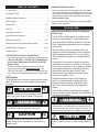
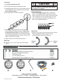
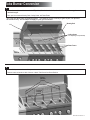
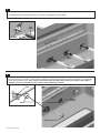
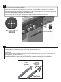
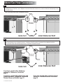
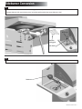
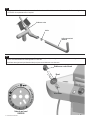
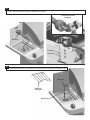
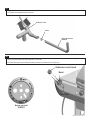
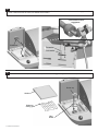
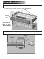
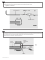
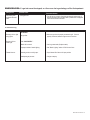
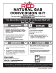
NATURAL GAS
CONVERSION
KIT
Model # 4984619
For use with Commercial Series Dual Fuel™ Grills only.
FOR OUTDOOR USE ONLY
This Natural Gas Conversion Kit can be used ONLY with
Dual Fuel™ grills.
WARNING
CALIFORNIA PROPOSITION 65
1. Combustion by-products produced when using
this product contain chemicals known to the State of
California to cause cancer, birth defects, or other
reproductive harm.
2. This product contains chemicals, including lead
and lead compounds, known to the State of
California to cause cancer, birth defects or
other reproductive harm.
Wash your hands after handling this product.
WARNING
DANGER
If you smell gas:
1. Shut off gas to the appliance.
2. Extinguish any open flame.
3. Open lid.
4. If odor continues, keep away from the
appliance and immediately call your gas
supplier or your fire department.
CAUTION
1. Failure to follow all manufacturer’s instructions could
result in serious personal injury and/or property
damage.
1. Read and follow all safety statements, assembly
instructions, and use and care directions before
attempting to assemble and cook.
2. Grill installation must conform with local codes,
regulations or in their absence with National Fuel
Gas Code, NFPA 54/ANSI Z223.1 (In Canada must
conform to CSA B 149.1).
2. Some parts may contain sharp edges-especially as
noted in the manual! Wear protective gloves if
necessary.
CONSUMER:
Keep this manual for future reference.
INSTALLER/ASSEMBLER:
Leave this manual with consumer.
If you have questions or need assistance during assembly, please call 1-800-241-7548 (USA) or 1-800-387-6057 (Canada)
To insure your satisfaction and for follow-up service, register your grill online at www.grillregistration.com
Natural Gas Conversion Kit • 3496258 • 09/29/07
TABLE OF CONTENTS
For Your Safety . . . . . . . . . . . . . . . . . . . . . . . . . . . . . . . . . . . . . . 1
Grill Service Center. . . . . . . . . . . . . . . . . . . . . . . . . . . . . . . . . . . 2
Installation Safety Precautions . . . . . . . . . . . . . . . . . . . . . . . . . . 2
Safety Symbols. . . . . . . . . . . . . . . . . . . . . . . . . . . . . . . . . . . . . . 2
Installation Safety Precautions
• This kit converts your grill for natural gas use at 7 inch water
column supply pressure. Verify supply pressure with your local
gas company. If supply pressure is different than 7 inch water
column pressure, contact a certified plumber for assistance.
Not for use with LP gas.
• If grill is certified for use in Canada, this conversion kit Does
Not nullify that certification.
Use and Care . . . . . . . . . . . . . . . . . . . . . . . . . . . . . . . . . . . . . 2-4
Parts List. . . . . . . . . . . . . . . . . . . . . . . . . . . . . . . . . . . . . . . . . . . 4
Tube Burner Conversion . . . . . . . . . . . . . . . . . . . . . . . . . . . . . 5-7
Natural Gas Hose Conversion . . . . . . . . . . . . . . . . . . . . . . . . . . 8
Sideburner Conversion. . . . . . . . . . . . . . . . . . . . . . . . . . . . . 9-11
Sideburner Conversion(Outdoor Stove & Griddle) . . . . . . . 12-14
Rotisserie Burner Conversion. . . . . . . . . . . . . . . . . . . . . . . .15-16
Troubleshooting . . . . . . . . . . . . . . . . . . . . . . . . . . . . . . . . . . . . 17
Call Grill Service Center for Help and Parts
• If you need assistance with your product or warranty parts call
1-800-241-7548 (USA) or 1-800-387-6057 (Canada) Hours of
Service Center Operation are 8:00 A.M. To 6:00 P.M. EST
Monday - Friday.
• To order non-warranty replacement parts or accessories
please visit us on the web at www.charbroil.com or call
1-800-241-7548 (USA) or 1-800-387-6057 (Canada) and one
of our friendly and knowledgeable agents will be glad to assist
you.
Safety Symbols
The symbols and boxes shown below explain what each heading
means. Read and follow all of the messages found throughout
the manual.
DANGER
DANGER: Indicates an imminently hazardous situation
which, if not avoided, will result in death or serious injury.
WARNING
WARNING: Indicates a potentially hazardous situation which,
if not avoided, could result in death or serious injury.
CAUTION
CAUTION: Indicates a potentially hazardous situation or
unsafe practice which, if not avoided, may result in minor or
moderate injury.
2 • Natural Gas Conversion Kit
USE AND CARE
Natural Gas Connections and Service Regulators
Above 1/2 psi.
Prior to 1998, all residual gas service regulators were
set with an outlet pressure of 7 inches water column.
In the 1998 edition of NFPA 54, the National Fuel Gas
Code, a change was made allowing service regulators
of 2 and 5 psi.
With this change it was also required that an in line
regulator be connected between the service regulator
and the appliance regulator if the 2 or 5 psi system is
used. This additional regulator is not supplied with the
product.
It is possible for a consumer, making the connection
themselves, or a plumber, not checking, to tap into a 2
or 5 psi line. If a pressure of 2 psi or greater is supplied
to the appliance regulator on certain grills it will shut
down and not deliver any gas to the grill. Other
concerns are the quick disconnect socket and hose
which are only rated to 1/2 psi.
If the quick disconnect socket, hose, and grill are
properly connected and still not getting gas, delivery
pressure needs to be verified. If pressure is greater
than 1/2 psi, make sure that an in line regulator is
present.
Once the grill has been over-pressured, the regulator
may or may not have been damaged. The best practice
is to replace the regulator.
WARNING
Do not attempt to repair or alter this conversion kit for any
assumed defect. Any modification to this assembly will void
your warranty and create the risk of a gas leak and fire. Use
only authorized replacement parts supplied by manufacturer.
DANGER
Incorrect connection can result in a gas leak with possibility of
fire.
This unit should be hard plumbed using components that
meet National Fuel Gas Code.
WARNING
Do not use flexible gas hose supplied for Drop-in Models.
4. When the quick disconnect socket and the gas hose are connected,
a valve in the socket opens automatically to permit full gas flow.
When the gas hose is disconnected, the valve in the socket instantly
and positively shuts off the flow of gas. Because the valve in the
socket positively shuts off the flow of gas, the grill can be
disconnected from the gas source by disconnecting the gas hose
from the quick disconnect socket. The socket should be left attached
to the gas source (house piping). Figure C, below, shows properly
connected hose and socket.
Connecting Your Grill to the Natural Gas Source.
1. A professionally-installed shut-off valve between the supply piping
and the socket is recommended, but not required, by the National
Fuel Gas Code. Socket connection must be made outdoors.
2. Coat the gas supply pipe nipple with gas resistant pipe dope or
approved teflon tape. Screw socket onto gas supply pipe (house gas
source) as shown in Figure A below, and wrench-tighten.
CAUTION
Figure C
The quick disconnect socket should never be connected
to the grill. Direction of gas flow is indicated on the
socket.
Quick disconnect socket
House piping
With proper assembly, the gas hose cannot be removed without
pushing the quick disconnect sleeve back. To disconnect, push
sleeve back and pull plug out of sleeve (this automatically shuts off
gas).
Please Note: Hose and assembly are C.S.A. listed for natural gas,
manufactured gas, mixed gas and for liquefied petroleum and for
LP Gas-Air mixtures on basis of 0.64 specific gravity for 1000
BTU’s per cubic foot of gas at 0.3 in. water column pressure drop.
Only ANSI Z21.54 approved hoses should be used with this grill.
Figure A
3. Pull back the sleeve on the quick disconnect socket and insert the
unattached end of the gas hose into the socket. Release the sleeve
and continue pushing the hose into the socket until the sleeve snaps
into the locked position. See Figure B.
Gas hose
The appliance and its individual shut off valve must be
disconnected from the gas supply piping system during any
pressure testing on that system at test pressures in excess of 1/2
psig (3.5kPa).
The appliance must be isolated from the gas supply piping system
by closing its individual manual shutoff valve during any pressure
testing of the gas supply piping system at test pressures equal to
or less than 1/2 psi (3.5kPa).
Sleeve
WARNING
Figure B
Do not use hard metal piping of any kind to connect this
type of grill to natural gas source. Use only hose
specified by manufacturer. Using hard metal piping or
convoluted metal tubing is an unsafe practice. Movement
of the grill can cause breakage of metal pipe.
Natural Gas Conversion Kit • 3
Leak Testing
CAUTION
1. Turn all grill control knobs to OFF.
2. Be sure gas hose is tightly connected to gas source.
3. Completely open gas source. If you hear a rushing sound, turn
gas off immediately. There is a major leak at the connection.
Correct before proceeding.
4. Brush soapy solution onto area circled below.
CAUTION: Sideburner lid must be open when sideburner
is in operation, if so equipped.
Burner Flame Check
• Remove cooking grates and flame tamers. Light burners,
rotate knobs from HIGH to LOW. You should see a smaller
flame in low position than seen on HIGH. Perform burner flame
check on sideburner also. Always check flame prior to each
use. If only low flame is seen refer to "Sudden drop or low
flame" in the Troubleshooting Section.
HIGH
LOW
5. If “growing” bubbles appear, there is a leak. Close gas
source immediately and tighten connection. If leaks cannot
be stopped do not try to repair. Call for replacement parts.
Order new parts by giving the serial, model number and name
of items needed to the Grill Service Center at 1-800-241-7548
(USA) or 1-800-387-6057 (Canada).
Hose Check
• Before each use, check to see if hoses are cut, worn or kinked.
Replace damaged hoses before using grill. Use only
valve/hose/regulator specified by manufacturer.
6. Always close gas source after performing leak test.
Safety Tips
Normal
Hose
s When grill is not in use, turn off all control knobs and gas
source.
PARTS LIST/DIAGRAM
Kinked
Hose
Note: Illustrations are not to scale.
Key Qty. Description
Part No.
A . . . . . 5 . . . . . Main Burner and Sideburner Natural Gas Bezel . . . . . . . . . . . . . . . . . . . . . . . . . . . . . . . 80004350
B . . . . . 1 . . . . . Stove and Griddle Natural Gas Bezel . . . . . . . . . . . . . . . . . . . . . . . . . . . . . . . . . . . . . . . 80004352
C . . . . . 1 . . . . . Orifice Removal Tool . . . . . . . . . . . . . . . . . . . . . . . . . . . . . . . . . . . . . . . . . . . . . . . . . . . . 80004378
D . . . . . 1 . . . . . 10 ft., 3/8” Natural Gas Hose . . . . . . . . . . . . . . . . . . . . . . . . . . . . . . . . . . . 3496263
E . . . . . 1 . . . . . Rotisserie Burner Orifice (Light Blue Dot-1.15mm) . . . . . . . . . . . . . . . . . . . . . . .80006910
A
B
C
D
Tools required for assembly:
Orifice Removal Tool - Provided Adjustable Wrench - Not provided
Estimated assembly time: 30-45minutes
4 • Natural Gas Conversion Kit
E
Tube Burner Conversion
1
- First, make sure all control knobs are in the OFF position, LP tank valve is closed, and tank is disconnected from regulator and
removed from grill.
- Next, open Lid and remove Warming Rack, Cooking Grates, and Flame Tamers.
Your Grill may differ from illustrations shown. This manual covers a variety of grills styles, use pictures
as reference only. Not all steps will apply to your grill conversion.
Warming Rack
Lid
Cooking Grates
(2 or 3 depending on Unit purchased)
Flame Tamers
2
- Remove Self-tap screws and remove Carryover tubes.
- Remove screws and washers at back of burners to detach Tube Burners from Burner Brackets.
Burner
Machine
Screws
Lock Washer
Carryover
Self-tap
Screws
Carryover
Tube
b
Tu
eB
r
ne
r
ne
ur
eB
ur
b
Tu
eB
r
ne
ur
ur
eB
r
ne
ur
eB
b
Tu
b
Tu
b
Tu
r
ne
Burner ts
Bracke
Natural Gas Conversion Kit • 5
3
- Remove two screws that secure each Electrode to Tube Burner (Electrode remains in Firebox).
- Lift back end of burner while sliding Tube Burner out of Firebox, disengaging burners from Valves.
Screws
Tube
Burner
Electrode
ox
ireb
ill F
f Gr
to
Fron
Tube
Valve
Tube
Burn
er
Burn
er
4
- Insert Orifice Removal Tool provided with Kit into Firebox Burner openings and unscrew Orifices from ends of Valves. Save removed Orifices
for converting back to LP Tank Gas. These grill valves are designed to work with Natural Gas once Orifices are removed. Do not replace any
Orifices when using Natural Gas. Note: This gas conversion kit comes with replacement Orifices for the Rotisserie Burner ONLY, if
applicable, do not use on Tube Burner valves. See later steps for Rotisserie conversion.
Valve
x
ebo
r
fG
to
ron
F
Orifice
Orifice Removal Tool
6 • Natural Gas Conversion Kit
ir
ill F
Burner
Opening
5
- Pull the Tube Burner Control Knobs off of Valve Stems.
- Remove screws and washers that secure each Bezel to the Control Panel. Save removed Bezels for converting back to LP Tank Gas.
- Install new Natural Gas Bezels provided with Kit (see illustration below) in place of old Bezels onto Control Panel, and secure using previously
removed screws and washers. Assure proper alignment with control knob before fully tightening. Note: New bezels will change the rotation
for the control knob to properly control ignition and flames for your grill.
- Press Control Knobs back onto Valve Stems. Make adjustments needed to Bezels for free movement of Control Knobs.
Bezels
Lock Washers
l
rol
ont
e
Pan
Valve
Stem
Screws
C
Natural Gas Bezel
80004350
Tube Burner
Control Knobs
6
Reinstall Tube Burners
- Attach Electrodes to Tube Burners with previously removed screws. Reference illustration Step 3
- Insert Tube Burners into Firebox Burner holes over Valves with port holes upward, making sure Tube Burner engages Valve properly, See
Below Diagram.
- Secure Tube Burners to Burner Brackets with previously removed screws and washers. Replace Carryover tubes and secure with screws
previously removed. Reference illustration Step 2.
Reinstall Flame Tamers, Cooking Grates, and Warming Rack, reference illustration Step 1 for reinstallation.
Correct
burner-to-valve
engagement
Incorrect
burner-to-valve
engagement
Tube Burner
Natural Gas Conversion Kit • 7
Natural Gas Hose Conversion
7
- Using a wrench, not provided, remove LP Regulator Hose Assembly from Manifold Connection. Saved removed LP Manifold Connection for
converting back to LP Tank Gas. Your LP Regulator hose will be located either inside the cart or under the sideburner shelf depending on what6
grill model you have.
Your Grill may differ from illustration shown.
Manifold
Connection
LP Regulator
Hose Assembly
Inside Cart
Under Sideburner Shelf
OR
8
- If Manifold connection is located inside cart, insert Natural Gas Hose (end opposite of Quick Disconnect) provided with Kit through rear side of
Back Panel Grommet and up to Manifold Connection. If sideburner connection, position hose behind cart up to Manifold Connection.
- Secure the Natural Gas Hose Assembly using a wrench, not provided, to Manifold Connection.
Manifold
Connection
Back Panel
Grommet
Natural Gas
Hose Assembly
Inside Cart
If you have a model with a sideburner
proceed to “Sideburner Conversion”
page 9
If you have a model with outdoor stove and
griddle proceed to “Sideburner Conversion
Outdoor Stove and Griddle” page 12
8 • Natural Gas Conversion Kit
OR
Under Sideburner Shelf
If you have a model with a rotisserie burner
proceed to “Rotisserie Burner Conversion”
page 15
Sideburner Conversion
9
- Open sideburner lid and remove the sideburner cooking grate, burner cap and wind diverter.
6
- Beneath sideburner shelf, remove the two screws, lock washers and flat washers that secure sideburner to shelf.
Burner cap
Sideburner
cooking grate
Wind diverter
10
- Remove sideburner from shelf.
6
Sideburner
Natural Gas Conversion Kit 9
11
- Using the provided orifice removal tool, unscrew the orifice from the end of the sideburner valve. Save removed orifice for converting back to
LP Tank Gas. No replacement orifice is required.
6
Sideburner valve
Orifice
Orifice removal tool
80004378
5
12
- Pull the sideburner control knob off of valve stem. Remove the existing bezel by removing the two screws and washers securing bezel to shelf
fascia. Save removed bezel for converting back to LP Tank Gas.
- Install new natural gas bezel (see illustration below) and press control knob back onto valve stem.
Sideburner control knob
Bezel
Valve stem
Natural gas bezel
80004350
10 • Natural Gas Conversion Kit
13
- Return sideburner to shelf. Make sure burner engages sideburner valve. See illustration below for correct burner-to-valve engagement. Secure
burner to shelf bracket with two screws, lock washers and flat washers.
Correct burner-to-valve
engagement.
Sideburner
Flat washer
Lock washer
14
- Place wind diverter and burner cap onto sideburner, then place sideburner cooking grate onto sideburner pan.
Burner cap
Sideburner
cooking grate
Wind Diverter
Natural Gas Conversion Kit 11
Sideburner Conversion (Outdoor Stove & Griddle)
15
- Open sideburner lid and remove the sideburner cooking griddle, burner cap and wind diverter.
6
- Beneath sideburner shelf, remove the two screws, lock washers and flat washers that secure sideburner to shelf.
Griddle
Burner cap
Sideburner
cooking grate
Wind
diverter
16
- Remove sideburner from shelf.
6
Sideburner
12 Natural Gas Conversion Kit
17
- Using the provided orifice removal tool, unscrew the orifice from the end of the sideburner valve. Save removed orifice for converting back to
LP Tank Gas. No replacement orifice is required.
6
Sideburner valve
Orifice
Orifice removal tool
80004378
5
18
- Pull the sideburner control knob off of valve stem. Remove the existing bezel by removing the two screws and washers securing bezel to shelf
fascia. Save removed bezel for converting back to LP Tank Gas.
- Install new natural gas bezel (see illustration below) and press control knob back onto valve stem.
Sideburner control knob
Bezel
Valve stem
Natural gas bezel
80004352
Natural Gas Conversion Kit 13
19
- Return sideburner to shelf. Make sure burner engages sideburner valve. See illustration below for correct burner-to-valve engagement. Secure
burner to shelf bracket with two screws, lock washers and flat washers.
Correct burner-to-valve
engagement.
Sideburner
Flat washer
Lock washer
20
- Place wind diverter and burner cap onto sideburner, then place sideburner cooking grate and griddle onto sideburner pan.
Burner cap
Griddle
Sideburner
cooking grate
Wind
diverter
14 Natural Gas Conversion Kit
Rotisserie Burner Conversion
21
- Remove screws, washers, and nuts that secures Rotisserie Cover to back of grill Firebox.
- Remove Rotisserie Cover, if applicable.
Your Grill may differ from illustration shown, it may not have a Rotisserie Cover.
Screw
Flat Washer
Lock Washer
Nut
NOTE: Your Grill may
not have bottom screws,
instead brackets are
present. If so, remove
top screws, washers and
nuts then pull cover
upwards to remove.
Rotis
Coverserie
22
- Using a wrench, not provided, remove Securing Nut from Rotisserie Connector. Slide Rotisserie Connector out from Rotisserie Support Bracket.
6
Securing
Nut
Rotisserie
Burner Tube
Rotisserie
Support Bracket
Rotisserie
Connector
Natural Gas Conversion Kit 15
23
- Using Orifice Removal Tool provided with Kit, unscrew Orifice from Rotisserie Connector. Save Orifice for converting back to LP Tank Gas.
- Replace with Natural Gas Orifice provided with this supplement and secure tightly to Rotisserie Connector.
* Light Blue dot - 1.15mm Orifice
Orifice Removal Tool
*Orifice
Light Blue Dot - 1.15mm
Rotisserie Connector
24
Reinstall Rotisserie Burner
- Insert Rotisserie Connector through cut-out of Rotisserie Support Bracket and tighten flush against bracket using previously removed Securing
Nut. Rotisserie Connector with Orifice should engage in Rotisserie Burner Tube. Reference illustration Below.
- Replace Rotisserie Cover, if applicable. Reference illustration Step 1.
Rotisserie
Burner Tube
Rotisserie
Support Bracket
½”
Rotisserie
Connector
Securing
Nut
Natural Gas Conversion Kit 16
6
EMERGENCIES: If a gas leak cannot be stopped, or a fire occurs due to gas leakage, call the fire department.
Emergencies
Possible Cause
Prevention/Solution
Gas leaking from
cracked/cut/burned
hose.
• Damaged hose.
• Turn off gas at at source. If anything but burned, replace parts. If
burned, discontinue use of product until a plumber has investigated
cause and corrections are made.
Troubleshooting
Problem
Burner(s) will not light
using ignitor.
Burner(s) will not
match light.
Flames blow out.
Possible Cause
GAS ISSUES:
• No gas flow.
Prevention/Solution
• Make sure gas hose is properly connected to grill. If hose is
properly connected, make sure gas source is turned on.
• See “GAS ISSUES:” .
• Match will not reach.
• Use long-stem match (fireplace match).
• Improper method of match-lighting.
• See “Match-Lighting” section of Grill Use and Care.
• Natural gas valve not fully open.
• Open Natural Gas Valve to full open position.
• Inadequate gas pressure.
• Call gas company.
Natural Gas Conversion Kit •17
THIS PAGE INTENTIONALLY LEFT BLANK
Natural Gas Conversion Kit 18
THIS PAGE INTENTIONALLY LEFT BLANK
Natural Gas Conversion Kit •19
Char-Broil, LLC ® Columbus, GA 31902 Assembly Instructions © 2007