1
Platinum CCTV Surveillance Solutions
http://platinum-cctv.com
Alnet VDR-S DVR Server
User’s Manual
Platinum CCTV Surveillance Solutions
http://platinum-cctv.com
Table of Contents:
1.0
Before Installation
1.1
1.2
1.3
1.4
1.5
1.6
2.0
Hardware Installation
2.1
2.2
2.3
2.4
2.5
2.6
3.0
Initial Software Setup
Main Camera Settings
Hard Drive Archive Setup
Network Settings Configuration
Program Settings Configuration
Scheduling Cameras
Audio Scheduler Configuration
Alarm Inputs Scheduler Configuration
System Alerts Scheduler Configuration
User Accounts Configuration
Audio Inputs Configuration
Input Settings (Optional)
Output Settings (Optional)
PTZ Dome Configuration (Optional)
Camera Dome Controls (Optional)
Saving your Configuration
VDR-S Server Operation
5.1
5.2
6.0
Software Installation
Driver Installation
VDR-S Server Software Configuration
4.1
4.2
4.3
4.4
4.5
4.6
4.7
4.8
4.9
4.10
4.11
4.12
4.13
4.14
4.15
4.16
5.0
DVR Card Installation
Watchdog Connection (Optional)
TV-Output Connection (Optional)
Video Input Connections
DI/DO Connection (Optional)
Audio Connection (Optional)
Software Installation
3.1
3.2
4.0
What’s in the Box
Product Specifications
Product Features
PC Requirements
Internet Connection Requirements
Hardware Overview
Main Camera Viewport
Archive Playback Mode
Troubleshooting VDR-S Server
6.1
6.2
6.3
6.4
6.5
6.6
Installation Problems
Initial Start-up Problems
Recording Problems
Remote Connection Problems
PTZ Camera Problems
User Account Setup Problems
1
1
2
2
3
3
4
6
6
7
9
10
13
15
16
16
20
22
22
25
37
38
47
51
57
60
61
62
66
68
71
73
76
78
80
80
92
103
103
105
108
110
113
116
Platinum CCTV Surveillance Solutions
http://platinum-cctv.com
Section 1.0 – Before Installation
1. Before Installation
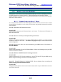
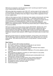
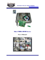
1.1 What’s in the Box
Inside your Alnet Systems DVR Card Packaging from Platinum CCTV Surveillance Solutions, you
will find the following components:
•
•
•
•
•
DVR Card(s) (D-500 Card Shown Above)
USB Dongle
Watch Dog Cable (2-Wire)
Alnet Systems Program CD
Installation Sheet w/Serial Number
All of these Items will be required during the installation process.
Do not discard any of these items.
At this Point, we are just checking the Inventory; Do not begin installation
until instructed, this will prevent unnecessary difficulties during the
installation process.
Alnet VDR-S Server User’s Manual
1
Platinum CCTV Surveillance Solutions
http://platinum-cctv.com
Section 1.0 – Before Installation
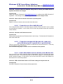
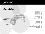
1.2 Product Specifications
Part #
D-500
D-500 x 2
D-500 x 3
D-500 x 4
D-700
D-700 x 2
D-600
Version
PRO4
PRO8
PRO12
PRO16
RT4
RT8
RT16
4
8
12
16
4
8
16
30
60
90
120
120
240
240
1
2
3
4
4
8
8/16
4/4
8/8
12/12
16/16
4/4
8/8
8/8
Video
Inputs
FPS (NTSC)
@ 640x480
Audio
Inputs*
Digital
I/O**
*Audio Requires Optional Expansion Module(s)
**Digital I/O Requires Optional Expansion Modules
1.3 Product Features
The Alnet VDR-S Pro DVR System is the latest development in Digital CCTV Surveillance
Technology. The system is specifically designed for video image recording and remote viewing.
VDR-S PRO system is available in four different versions: 4, 8, 12 and 16 channels. The 4, 8 and
12 channel versions are upgradeable to 16 channels by adding additional D-500 DVR Cards from
Platinum CCTV Surveillance Solutions. Video inputs are in groups of 4 on each video capture
card. A single video capture card can process from 30 (D-500) to 120 (D-700) frames per second
in NTSC (US standard Video format). Picture Parameters (key frames, color, saturation, quality,
etc.) can be adjusted manually by the user with individual settings for each camera.
Each system includes the following features:
• Complex System Scheduling
• Advanced Motion Detection, Continuous and Alarm Recording
• PTZ Control* w/Keyboard, Mouse and Joystick
• Email Alerts w/JPEG image files
• Auto Alarm when camera signal lost
• Unlimited User IDs with adjustable settings for viewing and remote access
• Remote Monitoring & Playback via PC, Laptop or PDA
• Remote Monitoring via Java or Symbian enabled cell-phones
• Smart-Search – Allows you to quickly scan through recorded video
• MPEG-4 / D-JPEG Video Recording Codecs
• High-Resolution Recording (up to 640x480)
• Dynamic IP Support (works with all Broad-band internet connections)
• Remote Client Software, Internet Explorer, or HTML embedded PC remote-viewing
• Watch-Dog Support to reboot PC if it hangs
• Preview mode – watch cameras while still picking up emails, browsing the internet
• Digital Watermark for security
*PTZ Control Requires PTZ Cameras & DI/DO expansion card
Alnet VDR-S Server User’s Manual
2
Platinum CCTV Surveillance Solutions
http://platinum-cctv.com
Section 1.0 – Before Installation
1.4 PC Requirements
Single D-500 Card Minimum Specifications:
•
•
•
•
•
•
•
Intel Processor PIII 1 Ghz
Intel Chipset motherboard*
256 MB RAM
HDD minimum 20 GB**
Network Adapter or Modem
Windows 2000/XP/Server 2003
64 MB AGP/PCIe Style Video Card*** (Recommended)
Multiple D-500 Card Minimum Specifications:
•
•
•
•
•
•
•
Intel Processor Celeron 1.3 Ghz +
Intel Chipset motherboard*
256 MB RAM
HDD minimum 20 GB**
Network Adapter or Modem
Windows 2000/XP/Server 2003
64 MB AGP/PCIe Style Video Card*** (Recommended)
Real-Time Card Recommended Specifications:
•
•
•
•
•
•
•
Intel Pentium IV Processor 2.0 Ghz +
Intel Chipset Motherboard*
512 MB RAM
HDD 80 GB +**
Network Adapter or Modem
Windows 2000/XP/Server 2003
64 MB AGP/PCIe Style Video Card***
* VDR-S Pro software works with VIA or SIS motherboards, but performance may be decreased slightly.
** Larger Hard Drive Size = Longer Recording Time
***VDR-S Pro System will work with Onboard Style video cards in Software Rendering mode.
1.5 Internet Connection Requirements
The Alnet VDR-S PRO DVR System does not require an internet connection for normal
recording/playback functionality. However, an internet connection will be required for remote
viewing capabilities.
While the Alnet VDR-S PRO software will operate with virtually any internet connection for remote
viewing (Modem, Cable, DSL, Satellite, etc.), the remote viewing quality and frame rate will be
determined by the speed of your connection. We recommend Broadband style (Cable, DSL, 2Way Satellite) internet connections with faster upload speeds for maximum performance of
Remote Viewing.
Alnet VDR-S Server User’s Manual
3
Platinum CCTV Surveillance Solutions
Section 1.0 – Before Installation
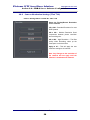
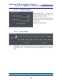
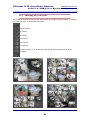
1.6 Hardware
Alnet VDR-S Server User’s Manual
4
http://platinum-cctv.com
Platinum CCTV Surveillance Solutions
Section 1.0 – Before Installation
Alnet VDR-S Server User’s Manual
5
http://platinum-cctv.com
Platinum CCTV Surveillance Solutions
http://platinum-cctv.com
Section 2.0 – Hardware Installation
2. Hardware Installation
2. 1 DVR Card Installation
2.1.1
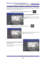
– Remove the Side-Cover of your PC
Most PCs have several screws holding the case together in the
back of the PC. Remove these screws, and slide off the side of the
PC Case.
Note: Your case design may differ. See the documentation
from your PC for disassembly instructions.
After removing the side of the PC Case, turn computer on its side.
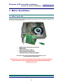
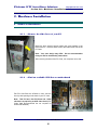
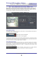
2.1.2
– Find an available PCI Slot on motherboard
The PCI Card Slots are off-white in color, and are
lined up with openings in the back of your PC case.
Note: This PC has 6 free PCI Slots and 1 AGP
slot that is occupied by an AGP video Card (AGP
Video Card Recommended but not required for
Alnet DVR Software)
Alnet VDR-S Server User’s Manual
6
Platinum CCTV Surveillance Solutions
http://platinum-cctv.com
Section 2.0 – Hardware Installation
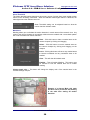
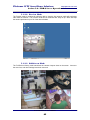
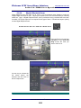
2.1.3
– Gently push DVR Card into PCI Slot
Carefully line up the Alnet
PCI DVR Card with an
available PCI slot, then
firmly seat the card into the
slot. Secure the card to the
back of the case.
2. 2 Watchdog Connection (Optional)
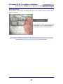
2.2.1 Connecting the Watchdog Cables
The Alnet VDR-S System comes with built-in watchdog support, which will reboot your PC if it
hangs or locks during system operation. Before you can enable the Watchdog function, you will
first need to connect the watchdog reset cables.
Watchdog Reset Cable included in the Alnet DVR Card
Package. This cable will connect between the DVR Card
Watchdog pins and the Reset Pins on the Motherboard.
Alnet VDR-S Server User’s Manual
7
Platinum CCTV Surveillance Solutions
http://platinum-cctv.com
Section 2.0 – Hardware Installation
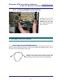
Locate the Reset wires leading to
your motherboard from the front of
your PC case. This is a small 2-pin
wire that is generally labeled “Reset
Sw” on the motherboard or on the
connector that plugs into the
motherboard.
(Consult PC or
Motherboard manual for specific
location)
Common labeling for most PC
manufacturer’s reset cable is shown
here. This cable should be connected
to the watchdog pins on the DVR Card.
Note: Not all PCs have a reset button,
therefore may not have a Reset SW
Cable
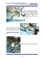
Completed Watchdog connections to DVR Card
Alnet VDR-S Server User’s Manual
8
Platinum CCTV Surveillance Solutions
http://platinum-cctv.com
Section 2.0 – Hardware Installation
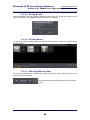
2. 3 TV-Output Connection (Optional)
2.3.1
Locating the TV-Output connector on your DVR Card
Each Alnet Systems DVR Card has a TV-Output built-in to the DVR Card. This TV-Output will
allow you to display the selected camera in REAL TIME onto a television or monitor with RCA
input. To cycle through cameras on the TV-Output, configure the Dynamic Layouts later in this
manual.
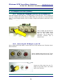
The TV output can be found on
the back of the DVR Card, directly
next
to
the
Video
Input
connectors. The TV output is an
RCA-style connector that is
Yellow in color.
2.3.2
Connecting the TV-Output to your TV
Use a standard RCA style cable to connect from the TV-Out terminal to the Television Line-In
RCA connectors.
Find an available video input on your TV like
this one, which will accept an RCA video input
Connect the RCA Cable from the TVOutput on the DVR Card to the Video
input on the Television
Alnet VDR-S Server User’s Manual
9
Platinum CCTV Surveillance Solutions
http://platinum-cctv.com
Section 2.0 – Hardware Installation
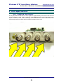
2. 4 Video Input Connections
2.4.1
Finding the Video Inputs
On the Alnet VDR-S DVR Card, the video inputs are located directly on the back of the card next
to the TV-Output terminal. Next to each Video Input BNC terminal, you will find a label for the
channel number (i.e. CH1, CH2, CH3, CH4). The 16-Channel Cards, such as the D-600, have
different style extension cables which have BNC terminals on their ends.
Alnet VDR-S Server User’s Manual
10
Platinum CCTV Surveillance Solutions
http://platinum-cctv.com
Section 2.0 – Hardware Installation
2.4.2
Connecting a BNC Terminal
CCTV Cameras and DVR Cards generally employ BNC style connectors. These connectors
create a good positive connection when installed properly. However, if not connected properly,
they can be a source of distortion or disconnection of your video signal.
Take the metal end of the
cable and press it firmly
onto the BNC Video port on
the back of the DVR Card.
Once you have pushed the
connector together, turn the
outside collar of the connector
approximately
90
Degrees
clockwise to lock it in place.
This connector is fully seated
Alnet VDR-S Server User’s Manual
11
Platinum CCTV Surveillance Solutions
http://platinum-cctv.com
Section 2.0 – Hardware Installation
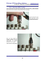
2.4.3
Adapting to an RCA Cable
Many installations may use a standard RCA-Style cable. In order to use an RCA style cable with
the Alnet Systems DVR Card Inputs, you will need to use a BNC to RCA adapter. This type of
adapter will also be needed if using a Budget-style CCTV Camera with a BNC type Cable.
A BNC to RCA adapter is
shown here being used
with a Camera that has a
BNC output, to adapt it to
an RCA style cable.
With an RCA style cable, a
second adapter would be
used between the cable
and the DVR Card.
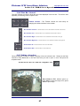
2.4.4
Ensuring good connection
Always test your connections to ensure that cables are fully seated. If the Alnet System is
displaying a blue screen instead of your camera’s image, then the most likely cause is incomplete
cable connection. Try to wiggle your cables and adapters to see if the camera’s image appears.
See the Troubleshooting Section for more details.
Alnet VDR-S Server User’s Manual
12
Platinum CCTV Surveillance Solutions
http://platinum-cctv.com
Section 2.0 – Hardware Installation
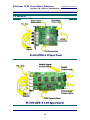
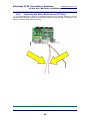
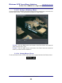
2. 5 DI/DO Connection (Optional Component)
2.5.1
Connecting DI/DO Card to DVR Card
The first connection for the DI/DO card is to connect the ribbon cable from the DI/DO Card to the
DVR Card.
Connection of Ribbon Cable to the DI/DO Card
Connection of Ribbon Cable to the DVR Card
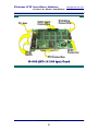
2.5.2
Connecting DI/DO Card to COM 1 Port (PTZ Only)
If the Digital Input/Output Accessory Card (Optional) is to be connected to a PTZ camera, the
supplied RS-232 Cable must be connected from the DI/DO Card to the COM 1 Port on the DVR
PC via Serial Cable.
RS-232 Cable connected to the RS-232 port
on the DI/DO card.
The Serial end of this cable will need to be
plugged in to the Serial COM1 port on the
back of the PC
Alnet VDR-S Server User’s Manual
13
Platinum CCTV Surveillance Solutions
http://platinum-cctv.com
Section 2.0 – Hardware Installation
2.5.3
Connecting RS-485 to PTZ Cameras (PTZ Only)
For PTZ applications, the center wires (Orange and Red) of the RS-485 connector must be
connected from the DI/DO expansion card to the RS-485 control wires of the PTZ Camera. Note
polarity of RS-485 cables when connecting.
Alnet VDR-S Server User’s Manual
14
Platinum CCTV Surveillance Solutions
http://platinum-cctv.com
Section 2.0 – Hardware Installation
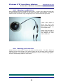
2. 6 Audio Connection (Optional Component)
The optional Audio Expansion card connects to the Alnet VDR-S DVR Card with a
single 2 wire connector. Simply mount the Audio card to the back of your PC case, then
connect with the supplied 2-wire cable to the DVR Card as shown.
Alnet VDR-S Server User’s Manual
15
Platinum CCTV Surveillance Solutions
http://platinum-cctv.com
Section 3.0 – Software Installation
3. Software Installation
3.1 Software Installation
Once the hardware has been properly installed and connected, reboot the PC. Once the PC has
finished loading windows, the Found New Hardware Wizard will open.
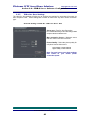
3.1.1
– Ignore the Found New Hardware Wizard
The Alnet System has not yet installed its drivers for
the DVR Card, so we will not continue the “Find new
Hardware Wizard” at this time. Don’t close the
window down, just move it off to the side.
IGNORE THIS WINDOW
MOVE it to the Side for now!
We will come back to the “Found New Hardware Wizard”
In Section 3.2 after software installation has completed
Complete Setup and Configuration of your Alnet VDR-S 2 System
16
Platinum CCTV Surveillance Solutions
http://platinum-cctv.com
Section 3.0 – Software Installation
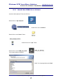
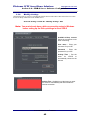
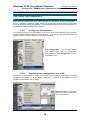
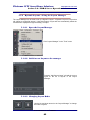
3.1.2
– Install Alnet VDR-S Server Software
Insert the Alnet Systems CD into the CD-Drive
Double-Click on “My Computer”
Double-Click on the “CD-Drive”
Double-Click on the “Server” Folder
Double-Click on the “Aps” Folder
Double-Click on the “VDRS_AV_Install”
file to begin software installation
Select Your Language then press “Next”
Complete Setup and Configuration of your Alnet VDR-S 2 System
17
Platinum CCTV Surveillance Solutions
http://platinum-cctv.com
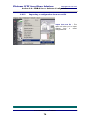
Section 3.0 – Software Installation
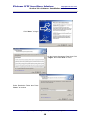
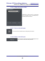
Click “Next >” to begin
On the License Agreement, Read, then Click
“I Agree” then Press “Next” 2 Times
Select Destination Folder then Press
“Next >” to continue
Complete Setup and Configuration of your Alnet VDR-S 2 System
18
Platinum CCTV Surveillance Solutions
http://platinum-cctv.com
Section 3.0 – Software Installation
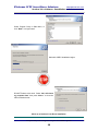
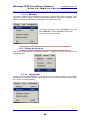
Select Program Group in Start Menu, or
click “Next >” to begin install
Wait while VDR-S Installation begins
DO NOT Reboot at this time! Select “No I will reboot
my computer later” then press “Next >” to close the
VDR-S Install window
Move on to Section 3.2 for Driver Installation
Complete Setup and Configuration of your Alnet VDR-S 2 System
19
Platinum CCTV Surveillance Solutions
http://platinum-cctv.com
Section 3.0 – Software Installation
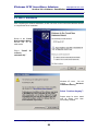
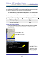
3.2 Driver Installation
After completing the Software installation, we will now return to the Found New Hardware Wizard
to complete the driver installation.
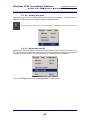
Return to the “Found
New Hardware Wizard”
Window that we set
aside earlier
Select “Install
software
automatically”
the
Windows XP users: You will
receive
a
“Hardware
Installation Warning”
Select “Continue Anyway”!
Repeat steps for driver install
until all drivers have been
successfully installed.
Complete Setup and Configuration of your Alnet VDR-S 2 System
20
Platinum CCTV Surveillance Solutions
http://platinum-cctv.com
Section 3.0 – Software Installation
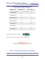
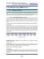
Consult the chart below for number of Audio and Video
Drivers that should install for Each DVR Card
DVR System
Audio Drivers
Video Drivers
PRO-4 (D-500)
1
1
PRO-8 (D-500 x 2)
2
2
PRO-12 (D-500 x 3)
3
3
PRO-16 (D-500 x 4)
4
4
RT-16 (D-600 x 1)
8
8
RT-4 (D-700 x 1)
4
4
RT-8 (D-700 x 2)
8
8
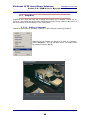
Plug USB Dongle into a USB Port on your PC
Windows will automatically find and install drivers for the USB Dongle
Now restart your PC
Once it reboots the Alnet VDR-S Software will open.
Move on to Section 4 for Initial Software Configuration
Complete Setup and Configuration of your Alnet VDR-S 2 System
21
Platinum CCTV Surveillance Solutions
http://platinum-cctv.com
Section 4.0 – VDR-S Server Software Configuration
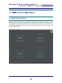
4. VDR-S Server Software Configuration
4. 1 Initial Software Setup
The first time the VDR-S software from Alnet runs, it will need to collect some information from
you in order to properly configure the software. Please complete the Initial Software Setup
exactly as described to prevent unnecessary problems.
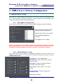
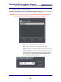
4.1.1
Auto-Update Configuration
On the first run of the VDR-S AV software, an Auto-Update Configuration window will appear.
Select “Yes, I do” to enable automatic
updating of the VDR-S application
Select the time frame for auto-updating
Select “Ask for permission” for
rebooting
Click “Apply” then click “Close”
Note: If your computer is not currently connected to the internet, you will receive an error
message stating that the server cannot be found. Close the warning message and ignore.
The Update selections will appear once your PC has been connected to the internet.
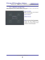
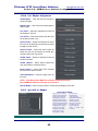
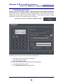
4.1.2
Initial Hardware Setup
Also on the initial run of the software, the Hardware Configuration will open to allow for the
configuration of the system. Be very careful to answer these questions correctly, to prevent
software problems later.
Sound Source - Select “Sound card
(DirectSound)” unless an Alnet audio extension
card will be used.
I/O Extension - Select I/O Extension boards if
purchased with the Alnet System
Video System - Select “NTSC” for U.S. Video
Format
Regional Settings – Choose Language and
Time/Date Format
Click “OK” to continue
Alnet VDR-S Server User’s Manual
22
Platinum CCTV Surveillance Solutions
http://platinum-cctv.com
Section 4.0 – VDR-S Server Software Configuration
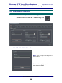
4.1.3
Initial User Account Setup
After configuring the initial hardware settings, you will be asked to enter a User Name and
Password (two times) to set up an Initial Administrator Account.
Enter a User Name
Note: The Login name is CaSe SeNsItIvE
as well as the password
Enter a Password
ReEnter Password
Note: The User account that is set-up in
this step, will be a FULL administrative
account with FULL RIGHTS to all
cameras. Do not loose or give out this
password to untrusted employees.
Alnet VDR-S Server User’s Manual
23
Platinum CCTV Surveillance Solutions
http://platinum-cctv.com
Section 4.0 – VDR-S Server Software Configuration
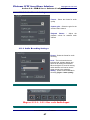
4.1.4
License Number Registration
To help prevent unauthorized installation of the Alnet Software, the software requires a License
number that is matched to the USB Dongle that was included with your system.
You can find the License number on the Information Sheet that was
provided with your Alnet VDR-S DVR Card.
The Serial Number will match the number on your USB Dongle,
The License number need to be entered to authorize the software.
Alnet VDR-S Server User’s Manual
24
Platinum CCTV Surveillance Solutions
http://platinum-cctv.com
Section 4.0 – VDR-S Server Software Configuration
4. 2 Main Camera Settings
Some of the most important configuration settings you will make on your Alnet VDR-S System,
are the Camera Settings. Available camera settings include brightness, contrast, resolution,
motion detection, audio recording, recording formats, display text, Dome (PTZ) settings and
framerate among others.
4.2.1
Entering Camera Settings
Main Viewer Screen > Click the “Camera” icon
4.2.2
Picture Settings (“Camera” Tab)
The Camera tab in the Camera Settings menu, will allow you to connect cameras, name your
cameras, control picture brightness, contrast, saturation, hue and sharpness as well as display
text. During the initial start-up, the main viewport will show any connected cameras in Black and
White. The Camera Tab will also allow you to change the Cameras to color.
The “Connect camera” button controls whether or not a camera is active.
Camera is Active and will display and record
Camera is Disconnected and will not display or record
Note: In VDR-S, when buttons are highlighted in Red-Orange, the button is active.
Alnet VDR-S Server User’s Manual
25
Platinum CCTV Surveillance Solutions
http://platinum-cctv.com
Section 4.0 – VDR-S Server Software Configuration
Click the Color Button shown below to set the camera to Color Mode.
Type a Name for the camera in the “Name” box. This is the camera name that can be displayed
on the camera viewport, and will be used for selecting a camera remotely.
Adjust Picture Settings (Brightness,
Contrast, Saturation, Hue and
Sharpness) to suit your installation
You can reset the adjustments to default by
pressing the “Default” button.
Alnet VDR-S Server User’s Manual
26
Platinum CCTV Surveillance Solutions
http://platinum-cctv.com
Section 4.0 – VDR-S Server Software Configuration
On-Display Text - Select the text to be displayed across the screen in the main viewport
Camera Name – Displays the Camera name
across the top left of the camera view
Current Time – Displays the current time
across the top right of the camera view
FPS – Displays the current frame rate
(Frames Per Second)
Text Color – Changes the color of all of the
Display text
Change All – Applies current settings to all
cameras
Alnet VDR-S Server User’s Manual
27
Platinum CCTV Surveillance Solutions
http://platinum-cctv.com
Section 4.0 – VDR-S Server Software Configuration
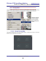
4.2.3
Camera Resolution Settings (“Res” Tab)
Camera Settings Menu > Click the “Res” tab
Select the Display/Record Resolution
for the cameras
320 x 240 – Standard Resolution for most
DVR Systems
640 x 240 – Medium Resolution Good
compromise between picture resolution
and recording size.
640 x 480 – High Resolution – The Best
quality Video Recording, takes up the
most space on the hard drive.
Apply to all – This will apply the new
resolution settings to all cameras.
Note: Any Changes to the resolution of
the cameras will not apply until the
software is shutdown and restarted.
Alnet VDR-S Server User’s Manual
28
Platinum CCTV Surveillance Solutions
http://platinum-cctv.com
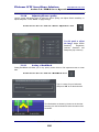
Section 4.0 – VDR-S Server Software Configuration
4.2.4
Camera Motion Detection Settings (“Motion” Tab)
Motion Detection allows cameras to record only when motion is occurring on-screen. Most DVR
Systems have very limited motion detection configuration settings, however the Alnet Systems
VDR-S software offers highly advanced and configurable motion detection settings, to allow you
to custom-tailor your system, so that it will record only the important motion.
Camera Settings Menu > Click the “Motion” tab
Camera Motion Indicator
The Camera motion indicator will show how much motion is currently detected, and whether or
not the motion alert is currently active.
Motion alert is currently not triggered
Motion alert is currently triggered
The Indicator bar shows the amount of motion that is presently detected. If the amount of motion
is higher than the Alarm Threshold setting, then the Red light will turn on and camera will record if
set to motion detection recording or trigger outputs if configured.
Camera Detection Sensitivity
The Camera Detection Sensitivity setting will allow you to adjust the sensitivity of the software
motion detection. The Detection sensitivity setting determines how many pixels have to change
before the group of pixels is considered to be motion. A setting with a lower number is less
sensitive than a higher number.
Detection Sensitivity setting around 24 is usually sufficient
sensitivity for most indoor or outdoor environments
Alnet VDR-S Server User’s Manual
29
Platinum CCTV Surveillance Solutions
http://platinum-cctv.com
Section 4.0 – VDR-S Server Software Configuration
Alarm Threshold
The Alarm threshold setting determines how many groups of pixels (dots) must register motion
before motion recording is activated. When the Indicator reads higher than the Threshold, the
alarm light next to the indicator turns red.
Alarm Threshold setting can be adjusted based on what the
motion detection indicator reads
Mask Area
Masking allows you to eliminate the motion detection in certain areas of the camera’s view. Any
areas of the camera viewport in the settings window that are masked with a cross-hatch pattern
will not be considered for motion detection.
Draw – Click this button to draw a masked area on the
camera viewport by clicking and dragging
Delete – Click this button to remove masked areas on
the camera viewport by clicking and dragging on the
viewport
Invert – Clicking this button will cause any masked areas
to become unmasked and any unmasked areas to be
masked
Clear – This will clear all masked areas
Enabled – This will enable Masking. This button must
be selected to view the masked area and to enable
masking
Change mask color – This button will change the display color of the masked area in the
Camera Settings viewport.
Example of a Camera Mask, this mask
has been set to prevent the tree blowing
in the wind from setting off motion
detection.
Alnet VDR-S Server User’s Manual
30
Platinum CCTV Surveillance Solutions
http://platinum-cctv.com
Section 4.0 – VDR-S Server Software Configuration
Show motion blocks
Clicking “Show motion blocks” will display white boxes on the Camera Settings viewport where
motion is detected.
Once the Show motion blocks button has
been selected, the viewport will show any
blocks where motion is currently detected.
Use a combination of the Mask, Sensitivity and Threshold settings to custom tailor the Motion Detection of your Alnet
Camera system to the needs of your particular area. This is one of the great benefits of Alnet Systems over most other
DVR Cards/Software. No other software gives you this level of customization abilities.
Alnet VDR-S Server User’s Manual
31
Platinum CCTV Surveillance Solutions
http://platinum-cctv.com
Section 4.0 – VDR-S Server Software Configuration
4.2.5
Camera Recording Settings (“Rec”Tab)
The Camera recording settings will allow you to configure the recording options for each camera,
including Recording Codec (MPEG-4 or D-JPEG), foreground quality, background quality and
schedule recording over-rides.
Camera Settings Menu > Click the “Rec” tab
Compression Settings - Select MPEG-4 for best quality
compression or DJPEG for greatest compression rate
“Preview” will show the average frame size and the
approximate space that would be used on the hard drive
with continuous 24 hour recording.
Key Frames - adjust the quality of the background of the
image (non-moving areas of the picture)
Delta Frames - adjust the quality of the foreground of the
image (moving areas of the picture)
Delta Sensitivity – This setting will adjust the sensitivity for separation of moving from
non-moving areas. This setting allows you to further adjust the compression when Key
and Delta Frames are adjusted separately.
“Disabled” - NORMAL SCHEDULED RECORDING will be used
“Motion Only” – The Camera will always record on motion
System will not use any scheduled recording sessions
when this button is selected
“Always” – The Camera will be on continuous recording
System will not use any scheduled recording sessions
when this button is selected
“Add Watermark” – This setting will record an invisible watermark to prove that the film has not
been tampered with. This is a useful feature if the video has to be used in a court.
Alnet VDR-S Server User’s Manual
32
Platinum CCTV Surveillance Solutions
http://platinum-cctv.com
Section 4.0 – VDR-S Server Software Configuration
4.2.6
Camera Frame-Rate Settings (“Frame”Tab)
One of the major advantages of the Alnet system over many of the other DVR Cards, is the ability
to independently adjust the framerate of each camera. This will allow you to achieve real-time on
most important cameras, while reducing the framerate on other cameras.
Note: These settings are not necessary with Real-Time Alnet DVR Cards
Camera Settings Menu > Click the “Frame ra” tab
Click on “Enable” to begin adjustment of camera framerates
Click the box next to one of the
cameras
Select the desired framerate for that
camera
Repeat for each additional camera
Note: the total framerate of all cameras will not exceed the maximum framerate of the DVR card.
Alnet VDR-S Server User’s Manual
33
Platinum CCTV Surveillance Solutions
http://platinum-cctv.com
Section 4.0 – VDR-S Server Software Configuration
4.2.7
Camera Sound Settings (“Sound”Tab)
Camera Sound Settings allows you to configure what audio channels will record or play with the
selected camera. You can even configure multiple cameras to record and play the same audio
input or multiple sound channels simultaneously.
Camera Settings Menu > Click the “Sound” tab
Highlight in Red the audio inputs for any audio that
you want to record and play with that camera.
If multiple audio channels are selected, it will
record/playback all selected channels
“Camera Visible” - Play the audio any time that camera was
visible on the main viewport
“Camera Selected” - Play the audio only when that camera
is selected on the main viewport
The VDR-S Software will always show 16 audio channels, regardless of how many active
channels of audio you have. However, it will only record from the active audio channels
that you have available and configured in audio properties
Alnet VDR-S Server User’s Manual
34
Platinum CCTV Surveillance Solutions
http://platinum-cctv.com
Section 4.0 – VDR-S Server Software Configuration
4.2.8
Other Camera Settings (“Other”Tab)
The other settings tab will allow you to configure events to occur after motion is detected, such
as: playing a sound, bringing camera to full-screen or showing text.
Camera Settings Menu > Click the “Other” tab
Alarms after Motion Detection
The Alarms after Motion Detection settings will allow you to program actions for the VDR-S
software to perform when motion is detected on that camera.
“Play Sound” – When highlighted, the system will be set to
play the sound selected in the “Sound file path” setting to the
right
“Show Camera” – This will bring the camera to full-screen in
the main viewer when motion is detected.
“Show Text” – This will show a small notification in the task
bar when viewer is in Preview or Minimized mode
“Invoke alarm after” – This setting selects the Time in
seconds that the highlighted actions above will trigger after the
motion is detected
Sound File Path – This setting will allow you to select a sound
file to play if “Play Sound” is selected for Motion Alert
Alnet VDR-S Server User’s Manual
35
Platinum CCTV Surveillance Solutions
http://platinum-cctv.com
Section 4.0 – VDR-S Server Software Configuration
4.2.9
Board Settings (“Board”Tab)
The Board settings will allow you to check on the status of the DVR Board, as well as changing
the Video System setting. The settings on the “Board” tab will automatically apply to the entire
system only after the program restarts.
Camera Settings Menu > Click the “Board” tab
PAL – European Standard for video
NTSC – US & Japan Standard for video
Detected Hardware – Shows if capture boards have been properly
detected and drivers loaded.
Repeat 4.2.2 through 4.2.9 for each Camera
After completing the configuration for each of the cameras,
press “Close” to apply the settings
Alnet VDR-S Server User’s Manual
36
Platinum CCTV Surveillance Solutions
http://platinum-cctv.com
Section 1.0 – Before Installation
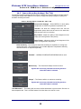
4.3 Hard Drive Archive Setup
Archive settings will allow you to set up your hard drive space for recording. The Alnet VDR-S
system will allow you to record to multiple drives or partitions and specify the size of your Archive
on each drive or location separately.
Main Viewer Screen > Click the “Archive” icon
Click “Add a new location” – This will add a new location under the “Path” heading.
Double-Click the Path listed under the “Path” heading
Double-Click the area under the “Size (MB)” – This will allow you to change the amount of space
in Megabytes that will be used on the hard drive for recording. It is recommended that you leave
at least 1000-2000MB remaining on the drive for windows to use.
Change the “File Size (MB)” – It is recommended that you leave this setting at 200MB for best
performance.
Check “Fast Formatting” - Allow the Archive location to format during the first recording cycle.
When selected, this setting will shorten the time for initial drive setup.
Click “Rebuild archive files” – Click this button to set up the Archive files on the hard drive.
Once you click “Rebuild archive files”, a progress bar will appear.
Once the rebuild is complete, the “Archive Settings” menu will close
Alnet VDR-S Server User’s Manual
37
Platinum CCTV Surveillance Solutions
http://platinum-cctv.com
Section 4.0 – VDR-S Server Software Configuration
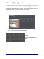
4.4 Network Settings Configuration
The Network Settings Panel of the VDR-S software will allow you to custom tailor the connection
options that your users will have available.
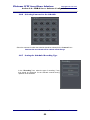
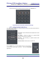
4.4.1
Entering Network Settings
Main Camera Viewport > Click the “Network Settings” Icon
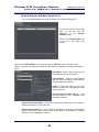
4.4.2
Video Settings
The Video Settings will configure the ability to connect to your Alnet VDR-S server with VDR-C
PC client and VDR-C PDA Client.
Network Settings > Click the “Video” Tab
Server Name – Enter a name for your DVR Server
Server Ports – Leave this section alone unless you
are experienced with network settings
Max Connection Count – Set the maximum number
of remote connections at one time.
Enabled – Enable incoming connections from VDR-C
Client
Register Dynamic IP –
The Dynamic IP registration will allow you to register your IP address with Alnet’s DDNS server
for free. This allows use of a dynamic IP broadband or dial-up internet connection to accept
incoming remote connections.
Domain Name – Enter the Address to use for remote connection
Name – Your business name
Address – Address of your business
Person – Your Name
Position – Your Position with the company
Publish Demo Server (Optional)– This will publish your demo
server for anyone to connect to it via a demo account
Register – This will register your information above with Alnet’s
DDNS server
Alnet VDR-S Server User’s Manual
38
Platinum CCTV Surveillance Solutions
http://platinum-cctv.com
Section 4.0 – VDR-S Server Software Configuration
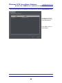
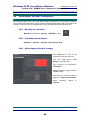
4.4.3
HTTP Settings
The HTTP settings will allow you to configure the remote web connection for your Alnet Systems
VDR-S software. This will only affect clients who connect in through Internet Explorer browser –
it will not affect clients connecting through the VDR-C remote Client settings
Network Settings > Click the “Http” Tab
Root Path – Leave this
setting alone (except for
advanced users)
Server port - should remain
at 80, except for advanced
users
Max connection count maximum number of users
that can connect via the
web client at one time
Click “Enabled” to enable
the web client for Internet
Explorer remote access
capabilities
Alnet VDR-S Server User’s Manual
39
Platinum CCTV Surveillance Solutions
http://platinum-cctv.com
Section 4.0 – VDR-S Server Software Configuration
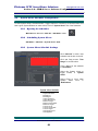
4.4.4
Remote Admin
The remote admin tab is provided for future use to remotely administer Alnet VDR-S system
settings. This module is currently under redevelopment.
Network Settings > Click the “Remote admin” Tab
Alnet VDR-S Server User’s Manual
40
Platinum CCTV Surveillance Solutions
http://platinum-cctv.com
Section 4.0 – VDR-S Server Software Configuration
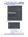
4.4.5
Video for Java Settings
The video for Java settings will allow you to configure the settings for users that will connect via
their cell-phone client. These settings will not have an affect over any other remote connection
type.
Network Settings > Click the “Video for Java” Tab
Server port – Port for Java Connection
It is recommended that you leave this setting at 9002
except for advanced network users
Max connection Count – Maximum users
that can connect via Java Cell-Client
Picture Quality - Select the picture quality for
cell-phone remote client users.
Lower Quality = Higher framerate
Higher Quality = Lower framerate
Note: You may have to tune these settings
later based on your mobile phone
connection speed.
Alnet VDR-S Server User’s Manual
41
Platinum CCTV Surveillance Solutions
http://platinum-cctv.com
Section 4.0 – VDR-S Server Software Configuration
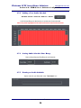
4.4.6
Dial-Up Settings
Configure the Dial-Up Access to automatically dial the internet and remain connected to allow for remote
access via dial-up connection on the VDR-S Server.
Network Settings > Click the “Dial-Up Settings” Tab
Note: You must already have a dial-up connection setup in Windows
before setting up the Dial-up settings in Alnet VDR-S
Available dial-up connect
Select the connection to use
when connecting.
User name – Enter your
username for your ISP
Password – Enter
password for your ISP
the
Activity Time – Set the
times
for
VDR-S
to
automatically connect to the
internet
Activity Time - Highlight in red the times you want
the server to automatically dial and maintain the
internet connection.
Alnet VDR-S Server User’s Manual
42
Platinum CCTV Surveillance Solutions
http://platinum-cctv.com
Section 4.0 – VDR-S Server Software Configuration
4.4.7
Router Settings
Most internet connections these days are protected by a router. The router will direct traffic from
the internet to the correct computer. If you are using a broadband-style internet connection, then
you will need to configure your router to send traffic to the correct IP address.
Note: Router settings are not made inside the VDR-S software. These are settings that
will have to be made on your specific cable-modem, DSL-modem or router. Consult
the documentation from your modem or router to find how to forward these ports.
The following ports will need to be forwarded to the internal IP address of your DVR PC.
Remote Connection Type
VDR-C Remote Client / PDA
HTTP (Internet Explorer)
Remote Administrator
Java Cell Phone Client
Port Forwarded
9000, 9001
80
8999
9002
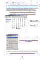
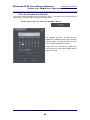
Finding your Internal IP Address
In order to find your Internal IP address, you will need to use the Windows XP command-line
tool. It is recommended that your DVR PC receives an internal static IP address (an address
which will not change). Consult your Network Administrator for details on changing IP
addresses and types.
Click Start Menu à Run
Type “CMD” and press “Ok”
Type “IPCONFIG” and
press Enter to continue
The IP address will be
listed on the command
screen
(i.e. 192.168.1.100)
Alnet VDR-S Server User’s Manual
43
Platinum CCTV Surveillance Solutions
http://platinum-cctv.com
Section 4.0 – VDR-S Server Software Configuration
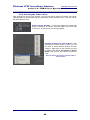
4.4.8
Windows Firewall Settings (Windows XP SP2)
With the introduction of Windows XP Service Pack 2, windows has implemented a built-in firewall
program. This firewall, as well as any other firewall software on your PC will have to be
reconfigured to allow remote access capabilities. Choose Easy or Advanced method below.
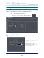
Easy Method (Disabling Windows Firewall)
1. Open
the
“Control
Panel” from the Start
Menu
2. Once the Control Panel
Opens,
find
the
“Security Center” and
double-click it.
Disabling Windows Firewall
Click “Off (not recommended)” then press “OK” to apply
the settings.
Your Win XP SP2 Windows Firewall has now
been disabled
Disclaimer: Platinum CCTV Surveillance Solutions provides this information as a free service to assist our customers.
Disabling a firewall on a PC that has
no other protection from possible internet attacks is not recommended, but may be the best solution for a basic user. Platinum CCTV cannot be held liable for
damage done to an unprotected PC left open to unrestricted internet access. Platinum CCTV Surveillance Solutions recommends using the advanced method of
Windows Firewall configuration, which will permit only mission-critical ports for the specific DVR Software you are using.
Alnet VDR-S Server User’s Manual
44
Platinum CCTV Surveillance Solutions
http://platinum-cctv.com
Section 4.0 – VDR-S Server Software Configuration
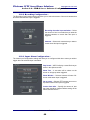
Advanced Method (Programming Windows Firewall Exceptions)
Open the “Control Panel” from the Start Menu
Once the Control Panel Opens, find the
“Security Center” and double-click it.
Programming Alnet Firewall Exceptions
Adding Alnet Port #1
1. Click on the “Exceptions” Tab
2. Click on the “Add Port...” Button
3. Type in “Alnet VDR-S 9000
TCP” in the “Name” box.
4. Type “9000” in the “Port
Number” box
5. Click the “TCP” button
6. Click ”OK” to add the Port
Adding Alnet Port #2
1. Click on the “Add Port...” Button
2. Type in “Alnet VDR-S 9000
UDP” in the “Name” box.
3. Type “9000” in the “Port
Number” box
4. Click the “UDP” button
5. Click ”OK” to add the Port
Alnet VDR-S Server User’s Manual
45
Platinum CCTV Surveillance Solutions
http://platinum-cctv.com
Section 4.0 – VDR-S Server Software Configuration
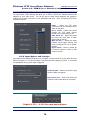
Adding Alnet Port #3
1. Click on the “Add Port...” Button
2. Type in “Alnet VDR-S 9001 TCP” in
the “Name” box.
3. Type “9001” in the “Port Number”
box
4. Click the “TCP” button
5. Click ”OK” to add the Port
Adding Alnet Port #4
1. Click on the “Add Port...” Button
2. Type in “Alnet VDR-S 9001 UDP” in
the “Name” box.
3. Type “9001” in the “Port Number”
box
4. Click the “UDP” button
5. Click ”OK” to add the Port
Double-Check your Settings
Once you have completed entering the 4 Alnet
Systems Ports above, your Exceptions window
should look something like this.
For Java Cell Connection, add port 9002 TCP and
UDP exceptions as well.
Your Windows Firewall is now configured
to accept Remote Connections for the
Alnet Systems Inc. DVR Cards.
Alnet VDR-S Server User’s Manual
46
Platinum CCTV Surveillance Solutions
http://platinum-cctv.com
Section 4.0 – VDR-S Server Software Configuration
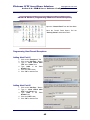
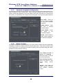
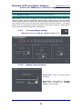
4.5 Program Settings Configuration
The Program Settings area of the VDR-S software will allow for configuration of e-mail server
settings, default photos settings, event log settings, snapshots settings as well as display and
system settings.
4.5.1
Entering Program Settings Menu
Main Camera Viewport > Click the “Network Settings” Icon
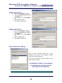
4.5.2
Mail Settings
The Alnet Systems Mail settings allow configuration of the e-mail servers and e-mail account from
which e-mail alerts will be sent. Without configuration of the settings in the Mail tab of Program
settings, e-mail alerts will not operate.
Server address and port – Enter
the server address and port for email configuration (provided by
your ISP)
Sender address – Enter the
email address that the e-mail
alerts will be sent from
Login* – Enter the login name
you use for your ISP email
Password* – Enter the password
for your ISP email
*Depending on your ISP (Internet Service Provider) and connection location, their server
may or may not require the Login and Password. If e-mail alerts do not function with
Login and Password, then try again with these fields blank
Alnet VDR-S Server User’s Manual
47
Platinum CCTV Surveillance Solutions
http://platinum-cctv.com
Section 4.0 – VDR-S Server Software Configuration
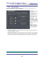
4.5.3
Photos Settings
The Photos settings will allow for configuration of photo save location and print settings.
File folder – Enter the
location where you would
like photo snapshots to be
saved.
Printer name – Select the
printer to use for printing
photos, or select “Always
Ask”
Paper orientation – Select
Portrait or Landscape
Print Scale – Select how to
scale
snapshots
when
printing
4.5.4
Event Log Settings
The event log settings of the Alnet VDR-S software, the location and size of event logs can be
configured.
File Folder – Enter the
desired location for the
Event Logs
Max size of an event log –
Select the maximum size of
each event log file
Alnet VDR-S Server User’s Manual
48
Platinum CCTV Surveillance Solutions
http://platinum-cctv.com
Section 4.0 – VDR-S Server Software Configuration
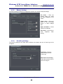
4.5.5
Automatic Snapshots Configuration
The automatic snapshots function will allow you to archive the latest video images directly onto a
local PC location, or onto a network drive. These automatic snapshots can be used to keep an
archive of what was happening, in case the system is shut down, powered off, or removed from
the location, you will still have JPG images of the last thing that occurred before system shutdown
File Folder – Enter the
local or network location
for saving the automatic
snapshots.
Update Interval – Enter
the time in seconds
between updates
Picture Quality – Select
the
quality
of
the
automatic snapshots
Enable – Select Enable to
begin network updates of
the automatic snapshots
4.5.6
Display Settings
The display settings tab of program settings in the Alnet VDR-S program will allow configuration
of software or hardware rendering as well as monitor power down. If the video card that is used
in the VDR-S Server is not sufficient for hardware rendering, then the DirectX setting will need to
be disabled to allow software rendering.
Turn display off after a
period of inactivity –
Select this option to shut off
monitor automatically
User inactivity time (sec) –
Select the amount of time
before
display
powers
down.
DirectX – This option will
toggle between Hardware
and Software rendering
modes
Alnet VDR-S Server User’s Manual
49
Platinum CCTV Surveillance Solutions
http://platinum-cctv.com
Section 4.0 – VDR-S Server Software Configuration
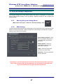
4.5.7
System Settings
The system settings tab will allow you to configure regional settings, system settings such as
system shell, watchdog and hardware configuration.
Language – Select
the language used
Time format – Select
desired time format
Date format – Select
desired Date format
Watchdog – Select
this setting to reboot
PC if the system locks
or hangs. (Watchdog
cable
must
be
installed)
System
shell
–
Select this setting to
prevent the user from
exiting the program.
Hardware configuration – Selecting this option will reset the hardware configuration the
next time the software is restarted
Key frame every 50 frames – Selecting this option will select the number of frames between
key frames. A lower number here will increase the size of video archives. A larger number
here will decrease the size of video archives, allowing more recording onto the same drive.
Alnet VDR-S Server User’s Manual
50
Platinum CCTV Surveillance Solutions
http://platinum-cctv.com
Section 4.0 – VDR-S Server Software Configuration
4.6
Scheduling Cameras
The Alnet VDR-S 2 Scheduler function is a large part of the advantage that the Alnet system has
over other DVR solutions. The Advanced Scheduling of Camera, Inputs, Outputs, System Alerts,
and Audio allow endless possibilities for the advanced configuration of your DVR solution and
integration with other systems such as Alarms, Home Automation Systems and many others.
Setting up multiple schedules will allow you to receive e-mail alerts on motion during critical
hours, without annoying you with constant e-mail alerts during times when Motion is expected.
Let’s take a look at how to configure the Scheduler, to help you get the most out of your Alnet
VDR-S server.
4.6.1
Opening the Scheduler
Main Viewer Screen > Click the “Scheduler” icon
Note: To use the scheduler to control camera recording, Recording must be set
to disabled for each camera in the “Camera Settings” à “REC” tab.
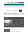
4.6.2
Adding a New Camera Schdedule
Camera Schedules will let you control the times, types of recordings, length of recordings and
Alerts triggered after motion detection for one or multiple cameras at a time.
Scheduler > Click the “Add new” button
Alnet VDR-S Server User’s Manual
51
Platinum CCTV Surveillance Solutions
http://platinum-cctv.com
Section 4.0 – VDR-S Server Software Configuration
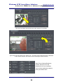
4.6.3
Setting the Schedule’s Time Range
Left-Click and Drag over the time bar to set the time for the schedule
Note: Only time highlighted in Red will be the active time for the schedule
Hint: Holding “Ctrl” on the Keyboard while dragging
and clicking will erase from the schedule.
4.6.4
Setting the Schedule’s Date Range
Select a Start Date and End Date for the Schedule –
Note: Start date of 01.01 and End date of 12.31 will apply schedule year-round
4.6.5
Naming your Schedule
Type a name for your Schedule in the “Task Name” box
Alnet VDR-S Server User’s Manual
52
Platinum CCTV Surveillance Solutions
http://platinum-cctv.com
Section 4.0 – VDR-S Server Software Configuration
4.6.6
Selecting Cameras for the Schedule
Select the cameras for which the schedule should be activated in the “Cameras” box –
Cameras that are selected will be outlined in Red-Orange
4.6.7
Setting the Schedule Recording Type
In the “Recording” box, select the type of recording, if any
that should be performed for the selected cameras during
operation of the schedule
Alnet VDR-S Server User’s Manual
53
Platinum CCTV Surveillance Solutions
http://platinum-cctv.com
Section 4.0 – VDR-S Server Software Configuration
4.6.8
Setting the Schedule Motion Detection Options
Recording Time after Motion Detection – Selects how long
you want the camera to record after it stops detecting motion
Motion Time – Selects how long motion needs to occur before
the camera will begin recording
4.6.9
Setting the Schedule Motion Detection Alerts
Send Email – This option will allow you to configure an
email alert after motion is detected – (See 4.6.10)
Set Outputs – This option will configure Motion on the
camera to trigger an output (optional Digital Input/Output
card) – This output could trigger lights, alarms, or virtually
any other low voltage device
Connect to Client – This option will connect to a client IP
address and notify that motion has been detected.
Alnet VDR-S Server User’s Manual
54
Platinum CCTV Surveillance Solutions
http://platinum-cctv.com
Section 4.0 – VDR-S Server Software Configuration
4.6.10 Setting the Schedule Email Alerts
If you click “Send e-mail” to set up an email alert, the “Emails” dialog opens.
The first time you set up an email
alert, you will not have any
addresses
in
the
“Choose
Address” dialog
Click on the “Address Book” tab
to set up a new email alert
location.
Once in the “Address Book” you will need to click the “Add new” button to create a new
address. After the new address is added, click the address to highlight it, and enter the settings
below.
Description – Enter a Unique name for the
email address that you are entering
Email Address – Enter the email address
that you will be sending the email alerts to
when this address is selected
Subject – Enter the Subject of the email
alert as you would like it to appear when the
email is received
Do not send more often than (s.) – The
minimum amount of time in between email
alerts that is desired
Attach Screenshots button – Click here to select the cameras that you would like to
attach screenshots for in the email alert
Get Screenshots after (s.) – This setting will determine how long the Alnet VDR-S
system should delay after sensing motion before taking a screenshots for selected
cameras. Time is displayed in seconds.
Alnet VDR-S Server User’s Manual
55
Platinum CCTV Surveillance Solutions
http://platinum-cctv.com
Section 4.0 – VDR-S Server Software Configuration
Once you have setup an email address in the address book, click the “Choose Address” tab
Check the box next to
the Address you set up
in the Address book.
Press “OK” to return to
the Scheduler
Alnet VDR-S Server User’s Manual
56
Platinum CCTV Surveillance Solutions
http://platinum-cctv.com
Section 4.0 – VDR-S Server Software Configuration
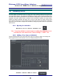
4.7
Audio Scheduler Configuration
The Alnet VDR-S 2 Scheduler function is a large part of the advantage that the Alnet system has
over other DVR solutions. The Advanced Scheduling of Audio Inputs, allows you to activate
Audio channels at specific times, and trigger camera recording, e-mail alerts, or trigger outputs
based on audio input.
4.7.1
Opening the Scheduler
Main Viewer Screen > Click the “Scheduler” icon
4.7.2
Scheduling Audio Inputs and Alerts
The Schedule Sounds Tab of the Alnet Scheduler will allow you to schedule Cameras to record,
Send Email Notifications, trigger outputs (w/optional DI/DO Card(s)) or Alert a client PC based on
Audio Detection.
Scheduler > Click the “Schedule Sounds” Tab
Alnet VDR-S Server User’s Manual
57
Platinum CCTV Surveillance Solutions
http://platinum-cctv.com
Section 4.0 – VDR-S Server Software Configuration
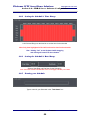
4.7.3
Adding a New Audio Schedule
Schedule Sounds > Click the “Add new” button
Left-Click and Drag over the time bar to set the time for the schedule
Note: Only time highlighted in Red will be the active time for the schedule
4.7.4
Setting Audio Schedule Date Range
Select a Start Date and End Date for the Schedule
4.7.5
Naming an Audio Schedule
Type a name for your Schedule in the “Task Name” box
Alnet VDR-S Server User’s Manual
58
Platinum CCTV Surveillance Solutions
http://platinum-cctv.com
Section 4.0 – VDR-S Server Software Configuration
4.7.6
Selecting Audio Channels to Activate
Select the audio inputs you wish the schedule to activate in the “Channels” box –
Channels that are selected will be outlined in Red-Orange
4.7.7
Setting Scheduled Audio Alerts
In the “After sound detection” box, select the action you wish to occur when sound detection on
the selected cameras occurs
Send E-mail – Send an Email Alert with snapshots when sound
is detected
Set Outputs – Control the outputs on an optional DI/DO
expansion card when sound is detected
Recording – Start Recording on specified cameras when
sound is detected
Connect to Client– Send an alert to a network PC
In the “Options” box, select the length of time you want cameras to
record after the sound input is activated – Used with “Recording”
option above
Alnet VDR-S Server User’s Manual
59
Platinum CCTV Surveillance Solutions
http://platinum-cctv.com
Section 4.0 – VDR-S Server Software Configuration
4.8
Alarm Inputs Scheduler Configuration
The Schedule Alarm Inputs Tab of the Alnet Scheduler will allow you to schedule Cameras to
record, Send Email Notifications, trigger outputs (w/optional DI/DO Card), Add a Bookmark to the
recording, or Alert a client PC based on Alarm Inputs from optional DI/DO Expansion card.
4.8.1
Opening the Scheduler
Main Viewer Screen > Click the “Scheduler” icon
4.8.2
Scheduling Alarm Inputs
Scheduler > Click the “Schedule alarm inputs” Tab
4.8.3
Alarm Inputs Schedule Settings
Click “Add new” to add a new
schedule into the box on the left
Click and Drag across
Range” to set active time
“Time
Type a Name for the schedule in
“Task Name”
Select the Inputs to trigger events in
“Inputs” section
Select Event to occur when Input is
triggered in “After input activation”
Select
Recording
“Options”
Alnet VDR-S Server User’s Manual
60
options
in
Platinum CCTV Surveillance Solutions
http://platinum-cctv.com
Section 4.0 – VDR-S Server Software Configuration
4.9
System Alerts Scheduler Configuration
To send System Alerts, Add Bookmarks, Trigger Outputs or Connect to a Remote Client from
User Logins, System Reboots or other events, Click on “System Alerts” Tab of the Scheduler
4.9.1
Opening the Scheduler
Main Viewer Screen > Click the “Scheduler” icon
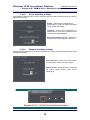
4.9.2
Scheduling System Alerts
Scheduler > Click the “System alerts” Tab
4.9.3
System Alerts Schedule Settings
Click “Add new” to add a new
schedule into the box on the left
Click and Drag across “Time
Range” to set active time
Type a Name for the schedule
in “Task Name”
Select the System Alerts to
trigger Events in “System
Alerts”
Select Event to occur when
System
Alerts
occur
in
“Notifications”
System Alerts Include:
Program Start up
Program Shut Down
Recording on
Recording off
Camera Connected
Camera Disconnected
Remote user login
Remote user login failed
Remote user log out
Local user log in
Local user log in failed
Local user logout
Video Signal restored
Video Signal lost
Alnet VDR-S Server User’s Manual
61
Platinum CCTV Surveillance Solutions
http://platinum-cctv.com
Section 4.0 – VDR-S Server Software Configuration
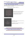
4.10
User Accounts Configuration
The User Accounts Settings are used for creating, editing, and assigning rights to Administrator
and User accounts. Each user can be given independent rights to cameras, audio, archives,
dome controls, inputs, outputs, and system settings and events.
4.10.1 Accessing User Account Configuration –
Main Viewer Screen > Click the “User Accounts” icon
Note: The user account that was created during the initial log in, will be listed in
the User Accounts – This initial user account has full administrative rights.
4.10.2 Adding New User Accounts
Adding a new user account will allow you to give another user rights to view cameras, inputs,
outputs, control PTZ Dome Cameras, or change system settings without having to give away your
administrator password.
Click the “Add User” button – To open “User Account” setup window
Alnet VDR-S Server User’s Manual
62
Platinum CCTV Surveillance Solutions
http://platinum-cctv.com
Section 4.0 – VDR-S Server Software Configuration
4.10.3 New User Account Setup –
4.10.4 User Details
Login – Enter the Username desired for the new account
(Note: Login is CaSe SeNsItIvE)
Password – Enter the Password for this user account
(Note: Password is CaSe SeNsItIvE)
Password Repeat – Enter the Password EXACTLY how entered
in the Password box
Alnet VDR-S Server User’s Manual
63
Platinum CCTV Surveillance Solutions
http://platinum-cctv.com
Section 4.0 – VDR-S Server Software Configuration
4.10.5 External Connections –
The External connections section of user setup allows restriction of login to specific IP addresses.
Leave this section blank unless you are very familiar with network protocols.
WARNING – Do not use this area if you are not VERY familiar with network operations!
Incorrect entries here will prevent Network connection to the system!
Add – Add an IP Address to the permitted IP list
Edit – Edit the details of an IP address that was added
Delete – Delete an IP address from the permitted IP address list
Check IP Address – This will force Alnet to always check the IP
address for the specified User against the permitted IP address
list. If the user is connecting from a different IP address, then
the user will not be permitted to login.
Alnet VDR-S Server User’s Manual
64
Platinum CCTV Surveillance Solutions
http://platinum-cctv.com
Section 4.0 – VDR-S Server Software Configuration
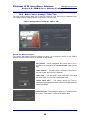
4.10.6 User Rights Assignment
Administrator – User will have full access to
all special rights
Regular User – User will have limited rights to
special rights
Live Video – Select the Cameras this user will
be allowed to view live
Live Sound – Select the Audio inputs this user
will be able to listen to live
Archive Video – Select the Cameras for which
this user will be allowed to access pre-recorded
footage from the archive
Archive Sound – Select the Audio inputs for
which this user will be allowed to access prerecorded audio from the archive
Visible inputs – Select the inputs this user will
be able to monitor
Visible outputs – Select which outputs this
user will be able to view and control
Dome Control – Select which PTZ Cameras
this user will be able to control
Time Restrictions – Select the login hours for
this user
NOTE – Time Restrictions MUST be set before exiting this screen!
New USERS will default to NO login hours allowed
Special Rights – Allow or deny access to certain Special Rights for the User
4.10.7 Special User Rights
Special User Rights
Adjusting Picture Settings
Changing Camera Settings
Changing Sound Settings
Changing Input Settings
Changing Output Settings
Changing Network Settings
Changing Scheduler Settings
Changing Memory Settings
Changing Dome Settings
Changing general Prog
Changing Card Settings
System Config Tools
Saving Photos on disk
Alnet VDR-S Server User’s Manual
65
Deleting Photos
Printing Photos
Archive Backups
Add/Delete Bookmarks
Exporting AVI file
Minimize Program
Browsing system logs
Full Dome Access
Program Shutdown
Enable or disable video
recording
Platinum CCTV Surveillance Solutions
http://platinum-cctv.com
Section 4.0 – VDR-S Server Software Configuration
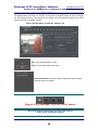
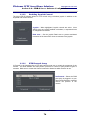
4.11
Audio Inputs Configuration
4.11.1
Accessing Audio Input Configuration –
Main Viewer Screen > Click the “Audio Settings” icon
4.11.2 Enable Audio Channel –
Name – Enter a unique name for you’re the
Audio Channel
Enable – When highlighted, selected audio
input channel is enabled
Alnet VDR-S Server User’s Manual
66
Platinum CCTV Surveillance Solutions
http://platinum-cctv.com
Section 4.0 – VDR-S Server Software Configuration
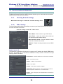
4.11.3 Audio Channel Settings –
Format – Select the format for audio
quality
Capture gain – Select the gain for the
selected audio channel
Playback Volume – Adjust the
playback volume for selected audio
channel
4.11.4 Audio Recording Settings –
Format – Select the format for audio
recording
Level – The level section has an
indicator light, indicator display and
slider bar for setting the threshold.
When the light is lit, sound is causing
audio detection and can be used to
trigger events in the scheduler
Quality – Select Audio bandwidth for
recording (higher = better quality)
Repeat 4.11.1 - 4.11.4 for each Audio Input
Alnet VDR-S Server User’s Manual
67
Platinum CCTV Surveillance Solutions
http://platinum-cctv.com
Section 4.0 – VDR-S Server Software Configuration
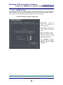
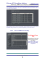
4.12
Input Settings (Optional: Expansion Card Required)
Digital Inputs can be used to integrate your Alnet VDR-S system with an alarm system, or any
other input sensors that can be used to trigger recording or send alerts through the VDR-S
program. A DI/DO expansion card is required to utilize digital inputs or outputs.
4.12.1
Accessing Input Settings –
Main Viewer Screen > Click the “Input Settings” icon
4.12.2 Input Configuration –
The Input Configuration Settings will allow you to select the normal configuration of your selected
input.
Input name – Type a unique name for
your input
Normal State – Select “NC” for
“Normally Closed” circuits and “NO”
for “Normally Open” circuits
Alnet VDR-S Server User’s Manual
68
Platinum CCTV Surveillance Solutions
http://platinum-cctv.com
Section 4.0 – VDR-S Server Software Configuration
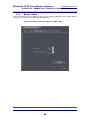
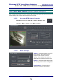
4.12.3 Recording Configuration –
The Recording Configuration settings will allow you to select the amount of time and cameras that
should record when the input is triggered.
Recording time after input activation – Select
the amount of time in seconds that you want the
selected cameras to record after this input is
triggered.
Cameras – Select each camera that you want to
record when this input is triggered
4.12.4 Input Alarm Configuration –
The Alarm Input Configuration settings will allow you to configure which other events you wish to
trigger when the selected input is activated.
Play Sound – VDR-S will play a sound file that you
select in the Options section
Show Text – A text alert will be shown on the
screen or will pop-up when triggered
Show Window – Selected camera will enter fullscreen mode when input is triggered
Go to preset – Selected PTZ camera can move to
a preset location when input is triggered
Invoke alarm after – Specify the amount of time
that input should be triggered before setting off the
alarms selected above.
Alnet VDR-S Server User’s Manual
69
Platinum CCTV Surveillance Solutions
http://platinum-cctv.com
Section 4.0 – VDR-S Server Software Configuration
4.12.5 Input Dome Control Settings –
The Input Dome Control Settings will allow you to control a PTZ Dome Camera based on the
triggering of your input device. You will be able to select Preset positions and timings to
customize the Dome movement to your installation and input. Note: Functioning PTZ Dome
Camera is required.
Dome – Select the PTZ dome
camera that will be controlled by the
alarm on this input
Go to preset – Select the preset
position the PTZ dome camera
should move to when alarm is set
After alarm off – Select the preset
the dome will move back to when
input trigger is cleared
Wait for (sec.) – Specify the delay
between input trigger clearing and
dome moving back to “Go to preset”
position
Go to Preset – Select a Preset for
PTZ dome camera to return to after
“Wait for” period.
4.12.6 Input Options and Settings –
Input Options and Settings will allow you to configure a custom sound file to play when the input
device is triggered. You can also specify if the sound should be played only once, or if it should
be repeated for as long as the input is triggered.
Sound file path – Select a sound file to play
when the alarm is triggered.
Play sound once – Sound file above will
continue to play unless this box is checked.
Repeat 4.12.1 – 4.12.6 for each desired input
Alnet VDR-S Server User’s Manual
70
Platinum CCTV Surveillance Solutions
http://platinum-cctv.com
Section 4.0 – VDR-S Server Software Configuration
4.13 Output Settings (Optional: Expansion Card Required)
Digital Outputs can be used to integrate your Alnet VDR-S system with an alarm system, light
controllers, HVAC systems, Garage Door Controls, Entry systems and any other low-voltage
outputs. Outputs can be controlled from the VDR-S software on the DVR server, the VDR-C client
on a remote PC and even from a PDA phone with the VDR-C client for Pocket PC. The VDR-S
solution is the next step towards complete integration of your home or business. Output controls
require use of an Alnet DI/DO expansion card (optional).
4.13.1
Accessing Output Settings
Main Viewer Screen > Click the “Output Settings” icon
4.13.2
Output Control Settings
Output name – Type in a unique name for
this output
Active State – Select “NO” for a “Normally
Open” circuit or “NC” for a “Normally
closed” circuit active state
Alnet VDR-S Server User’s Manual
71
Platinum CCTV Surveillance Solutions
http://platinum-cctv.com
Section 4.0 – VDR-S Server Software Configuration
4.13.3
Event Switching Settings
Event Switching Settings can be used to customize the output style and timing when the output is
triggered by an event.
Pulsate – When output is triggered by a
system alarm or event, the output will pulsate
on and off with this setting
Triggered – When output is triggered by a
system alarm or event, the output will be held
on for the time specified below
Hold output switched on for – Specify the
amount of time to hold triggered outputs on
4.13.4
Manual Switching Settings
Manual Switching settings can be used to customize the output style and timing when the output
is triggered manually.
Auto switch off – Specify if you want outputs
to automatically return to the “Off” position
Switch off after – Select the time (in seconds)
the output should remain active before
switching off
Repeat 4.13.1 – 4.13.4 for each desired output
Alnet VDR-S Server User’s Manual
72
Platinum CCTV Surveillance Solutions
http://platinum-cctv.com
Section 4.0 – VDR-S Server Software Configuration
4.14 PTZ Dome Configuration (Optional: Expansion Card Required)
The PTZ Dome Configuration section will allow you to enable a Protocol, and set control types, to
allow control of a PTZ Dome camera with your Alnet VDR-S DVR System.
4.14.1
Accessing PTZ Dome Setup
Main Viewer Screen > Click the “Dome Settings” icon
4.14.2
Enabling PTZ Dome Control
Enable – Click this button to enable PTZ Dome Control
Alnet VDR-S Server User’s Manual
73
Platinum CCTV Surveillance Solutions
http://platinum-cctv.com
Section 4.0 – VDR-S Server Software Configuration
4.14.3
Enabling Joystick Control
The Alnet VDR-S Software allows for PTZ control using a windows joystick in addition to the
keyboard and mouse controls.
Joystick – When highlighted, Joystick controls are active. Alnet
VDR-S uses any joystick installed in windows, no separate drivers
or configuration is needed.
Dead zone – Set the joystick Dead zone to prevent accidental
movement of the dome from minor movements of the joystick.
4.14.4
PTZ Protocol Setup
A Protocol is the language that a PTZ-style camera must use to control the movement of the
camera. The Alnet software has many built-in protocols for control of many different types of
cameras. Make sure to consult the Camera’s manual to determine which Protocol to use.
Set Protocol – Select the COM
port which is plugged in to your
Alnet DI/DO expansion card and
choose the protocol of the
camera
Alnet VDR-S Server User’s Manual
74
Platinum CCTV Surveillance Solutions
http://platinum-cctv.com
Section 4.0 – VDR-S Server Software Configuration
4.14.5
PTZ Keyboard/Mouse/Joystick Settings
In the Keyboard/Joystick/Mouse section, you can reprogram the buttons and keystrokes that will
control the PTZ Dome Camera.
Setup Keystroke actions for each of the Keyboard, Joystick and Mouse controls. Note: Some of
the Default settings “Parameter” may need to be adjusted for your PTZ dome camera.
4.14.6
Advanced PTZ Protocol Settings
For Advanced Users
Only
Click the Protocols Tab to edit
the PTZ Protocols to match
your camera.
Consult with the Mfg. of your
Dome camera before editing
the protocols
Alnet VDR-S Server User’s Manual
75
Platinum CCTV Surveillance Solutions
http://platinum-cctv.com
Section 4.0 – VDR-S Server Software Configuration
4.15 Camera Dome Controls (Optional: Expansion Card Required)
After Configuring the Main PTZ Dome Protocol and controls, you will now need to return to the
Camera Settings, to configure Camera specific PTZ controls.
4.15.1
Accessing PTZ Camera Controls
Main Viewer Screen > Click the “Camera Settings” icon
Click the “Dome” Tab to access Dome Settings
4.15.2
Dome Settings
Address – Enter the Address of your PTZ
Dome camera. Most cameras have
jumpers or DIP switches to set the
address. If the address here does not
match the dome, the dome will not move.
Protocol – Select the COM?:Protocol that
was set up in previous Dome configuration
Dome Enabled – Click this button to
enable PTZ Control for this camera
Alnet VDR-S Server User’s Manual
76
Platinum CCTV Surveillance Solutions
http://platinum-cctv.com
Section 4.0 – VDR-S Server Software Configuration
4.15.3
AutoPan Settings
Activate time (sec) – Time after last
manual movement that PTZ camera will
begin auto-panning if enabled
Preset time – Select the length of time the
camera should stay at each preset while
auto-panning
AutoPan – Enable AutoPan
4.15.4
Preset Mask
Preset Mask – Select the Preset positions from each group, that you want the camera
to auto-pan through. The camera will move through selected presets in sequential
order
Alnet VDR-S Server User’s Manual
77
Platinum CCTV Surveillance Solutions
http://platinum-cctv.com
Section 4.0 – VDR-S Server Software Configuration
4.16 Saving your Configuration
Once you have configured the Alnet VDR-S System, you will want to save the configuration. If
the PC is shutdown improperly without saving, the configuration changes that you have made
would default back to the original settings. It is recommended that you save the configuration file,
and then also export it to a text file as a backup.
4.16.1
Saving your Configuration
It is important to save your configuration any time you have made changes to the schedule,
camera settings, network settings or layout settings. If you do not save the configuration, all
settings will be lost if the PC shuts down or reboots improperly.
Save Configuration – On the Alnet VDR-S
main viewer screen, open the Configuration
menu and select “Save Configuration” to save
all settings to a file.
4.16.2
Exporting your configuration to text file
Exporting your configuration to a text file is a useful tool for archiving past setups, forwarding
configuration information on to our service department, or sharing a preconfigured file with
multiple DVR Servers for ease of setup.
Export to text file – This option
will save all of the settings to a
file on the hard drive.
Alnet VDR-S Server User’s Manual
78
Platinum CCTV Surveillance Solutions
http://platinum-cctv.com
Section 4.0 – VDR-S Server Software Configuration
4.16.3
Importing a configuration from a text file
Import from text file – This
option will allow you to import
settings
from
a
saved
configuration file.
Alnet VDR-S Server User’s Manual
79
Platinum CCTV Surveillance Solutions
http://platinum-cctv.com
Section 5.0 – VDR-S Server Operation
5. VDR-S Server Operation
5.1 Main Camera Viewport
Most of your time will be spent in the main camera viewport, viewing live cameras. So it is
important to get to know how to customize your environment. In this section, we will discuss how
to arrange your cameras in Screen layouts, take snapshots of your cameras, view the event log,
automatically rotate between layouts, access menu items, keep an eye on hard drive usage, and
watch for system alerts.
Alnet VDR-S Server User’s Manual
80
Platinum CCTV Surveillance Solutions
http://platinum-cctv.com
Section 5.0 – VDR-S Server Operation
5.1.1
Changing Screen Layouts
One of the most common tasks you will perform while in the Main Camera Viewport, is changing
the camera layouts. So we will look at this first.
Single Camera
4-Camera
8-Camera
10-Camera
13-Camera
16-Camera
Dynamic Layout – This will begin to cycle through layouts selected in the layout
manager
Alnet VDR-S Server User’s Manual
81
Platinum CCTV Surveillance Solutions
http://platinum-cctv.com
Section 5.0 – VDR-S Server Operation
5.1.2
Dynamic Layouts – Using the Layout Manager
The Layout Manager can be used to set up a Dynamic Layout. A Dynamic Layout is a layout that
will change at a specified interval. Using the Dynamic Layout will also automatically switch the
camera that is displayed through the analog TV output.
5.1.2.1 Open the Layout Manager
Click “Layout Manager” in the “Tools” menu
5.1.2.2 Add Current Layout to the manager
Pressing “Add Current layout” will add the current
layout to the list of layouts in the Layout
Manager.
5.1.2.3 Changing Layout Order
Use the Up and down arrows in the “Layout Manager” to change
the order of layouts.
Alnet VDR-S Server User’s Manual
82
Platinum CCTV Surveillance Solutions
http://platinum-cctv.com
Section 5.0 – VDR-S Server Operation
5.1.2.4 Change Layout Preset Time
Double-Click on the time next to a layout and
type in the amount of time (in seconds) that you
want the layout to be active for
5.1.2.5 Preview Selected Layout
You can preview the selected layout by clicking the preview button.
5.1.2.6 Remove Selected Layout
You can remove a layout from the list by highlighting the layout
that you want to remove and clicking “Remove”
Alnet VDR-S Server User’s Manual
83
Platinum CCTV Surveillance Solutions
http://platinum-cctv.com
Section 5.0 – VDR-S Server Operation
5.1.3
Viewing Modes
The Alnet VDR-S system allows you to select from several different viewing modes while viewing
cameras. Select between Normal Mode, Preview Mode, Full Screen Mode and Minimize.
Right-Click anywhere
on the main viewport,
and select “Display
mode” à then select
Normal, Fullscreen or
Preview
5.1.3.1 Normal Viewing Mode
The Normal Viewing mode is the most versatile setting, it includes easy access to the layout
selection, menu, setting menus and task bar.
Alnet VDR-S Server User’s Manual
84
Platinum CCTV Surveillance Solutions
http://platinum-cctv.com
Section 5.0 – VDR-S Server Operation
5.1.3.2 Preview Mode
The Preview mode is excellent for still being able to view the live cameras, while still performing
other tasks in windows. The Preview mode can be combined with “Stay on top” which will keep
the camera preview on top of all of the other windows.
5.1.3.3 Full-Screen Mode
The Full-Screen Viewing mode maximizes the camera viewport sizes on the screen. Access to
the menu bar, and other settings have been removed.
Alnet VDR-S Server User’s Manual
85
Platinum CCTV Surveillance Solutions
http://platinum-cctv.com
Section 5.0 – VDR-S Server Operation
5.1.3.4 Minimize
The Camera Viewport can be minimized to allow you to perform other tasks in windows. If the
Show Alert on Motion setting is selected in the camera settings, a small balloon will appear when
motion is detected on each camera, showing when the motion is detected.
To minimize the program, click the “Program” menu, and
select “Minimize” or press “Ctrl+M” to minimize the
program and return to Windows
5.1.4
Exiting the Program
Alnet offers several options for exiting the program:
Restarting the PC.
Logging out, Exiting the Program and
5.1.4.1 Logging Out
Logging out of the VDR-S System will allow the cameras to continue recording, but will disable
the camera live viewing and settings. While logged out, a user must log in before shutting down
the program, or viewing cameras.
Alnet VDR-S Server User’s Manual
86
Platinum CCTV Surveillance Solutions
http://platinum-cctv.com
Section 5.0 – VDR-S Server Operation
5.1.4.2 Exiting Program
Exiting the program will close all program functions and return to windows. If “System Shell” is
enabled in system settings, then Exiting Program will shut down the PC.
Exit the program by pressing the X in the bottom right, or through the program menu at the top
5.1.4.3 Restarting the PC
Restarting the PC will completely shut down all Alnet VDR-S system functions and restart your
PC. Alnet VDR-S will restart once windows boots, recording will begin immediately upon restart if
scheduled to record, however a user will have to login to view any of the live cameras.
Click on the “Program” Menu then select “Restart PC” to restart the PC.
Alnet VDR-S Server User’s Manual
87
Platinum CCTV Surveillance Solutions
http://platinum-cctv.com
Section 5.0 – VDR-S Server Operation
5.1.5
Snapshots
Snapshots are a quick and easy way of taking JPG images of live cameras. Photos can be
saved as a JPG image and can be easily accessed through the “Photos” section at the bottom of
the main viewport or printed directly to your photo printer.
5.1.5.1 Taking a Snapshot
Snapshots can be taken by pressing “Control-S” or right clicking and selecting “Snapshot”
Right-Click on the Camera you would like to save as a snapshot.
Select “Snapshot…” from the pull-down menu. (Or simply select
the camera and press “Ctrl-S”)
Alnet VDR-S Server User’s Manual
88
Platinum CCTV Surveillance Solutions
http://platinum-cctv.com
Section 5.0 – VDR-S Server Operation
5.1.5.2 Saving the File
Once a snapshot is taken, the snapshot dialog will open to allow you to save the images or print
the pictures directly. Click “Save” then type a name for the snapshot.
5.1.5.3 Viewing Photos
To view all thumbnails of stored snapshots, click the “Photos” button. Photos can be viewed and
printed if desired.
5.1.5.4 Filtering Photos by Date
To view stored snapshots for a specific date range in the Photos Viewer, Select the date on the
right side of the Photo Viewer.
Select a date and press the filter button to filter the photos
by date
Alnet VDR-S Server User’s Manual
89
Platinum CCTV Surveillance Solutions
http://platinum-cctv.com
Section 5.0 – VDR-S Server Operation
5.1.5.5 Saving or Printing a Photo
To Print a stored Photo snapshot, first select the photo from its thumbnail image, and double click
to open the photo viewer. The selected photo will appear in a larger window.
To Print – Click the “Print” button at the bottom of the Photo Viewer, then select the
printer and photo size to print.
To Save – Click the “Save” button at the bottom of the Photo Viewer then select the
location you want to save the snapshot in.
5.1.5.6 Closing Photos Viewer
To close the Photos Viewer, click the down arrow at the top right hand side of the Photos Viewer.
Alnet VDR-S Server User’s Manual
90
Platinum CCTV Surveillance Solutions
http://platinum-cctv.com
Section 5.0 – VDR-S Server Operation
5.1.6
Viewing Event Log
The Event Log in the Alnet VDR-S Software stores every action that occurs on the DVR Server.
Viewing the Event log will help to troubleshoot many different problems that you may be
experiencing, as well as showing user logins, system setting changes, remote logins, etc.
5.1.6.1 Opening the Event Log
The Event Log can be viewed directly in the VDR-S Software by clicking on the “Log Browser”
Button at the bottom of the screen.
5.1.6.2 Closing the Event Log
To Close the Event Log, click the Down Arrow at the Top Right of the Event Log Screen.
5.1.6.3 Changing the location of the Event Log
The location of the Event log can be changed in the “Program Settings” on the “Event Log” Tab.
Under “File Folder” you can see the current location of the Event Logs, or change their location.
It will be important to know the location of the Event Log, in order to receive technical support.
Alnet VDR-S Server User’s Manual
91
Platinum CCTV Surveillance Solutions
http://platinum-cctv.com
Section 5.0 – VDR-S Server Operation
5.2
Archive Playback Mode
The Archive Playback mode will allow you to playback any pre-recorded video that is stored in the
archives of your VDR-S DVR Server. Alnet has made reviewing the pre-recorded video very
easy by incorporating the use of the Time Bar. The time bar will show all recorded footage from
any visible cameras, to show you when your cameras recorded. This is especially helpful in
situations where motion detection recording is used. In this section, we will discuss all of the
controls and features that are available for use when operating the archives of your VDR-S
Server.
5.2.1 Opening Archive Playback Mode
Main Viewer Screen > Click the “Archives” icon
Alnet VDR-S Server User’s Manual
92
Platinum CCTV Surveillance Solutions
http://platinum-cctv.com
Section 5.0 – VDR-S Server Operation
5.2.2 Selecting Day for Playback
The Archive Viewer will default to the current day’s video. If you want to view a different day’s
video archives, you will need to click on the Calendar button.
Archive Viewer Screen > Click the “Calendar” button
The Calendar will open. Any days that are
highlighted in bold print are days that have
video recordings. Any days that are not in bold
have no video recordings for that day.
Simply click on the day that you would like to
view archives for, and press the “OK” button to
apply the settings.
Alnet VDR-S Server User’s Manual
93
Platinum CCTV Surveillance Solutions
http://platinum-cctv.com
Section 5.0 – VDR-S Server Operation
5.2.3 Selecting the Camera View
After selecting the day for your archives, you will now want to select the camera view layout.
Half-way down on the left hand side, you will find the Layout Selection Icons. Click the Icon for
the layout that you want.
Archive Layout Selection – In this area, select the number and
layout of cameras to be viewed. With Alnet VDR-S, you will be able
to view up to 16 cameras at once during playback.
Selecting a Camera for each viewport – After
selecting the Archive Viewer Layout, you are
also able to select different cameras for each
viewport. Right Click on the Camera you want
to change, then Select “Set Camera > {Server
Name}” and click on the camera you want to
view.
Note: The time-bar will change to reflect the cameras
that are selected.
Alnet VDR-S Server User’s Manual
94
Platinum CCTV Surveillance Solutions
http://platinum-cctv.com
Section 5.0 – VDR-S Server Operation
5.2.4 Selecting the Time for Playback
Selecting the Time for Playback is easier with the Alnet VDR-S Server system than it is with any
other DVR System. Simply left click on the time-bar to move the cursor to the time you are
currently hovering over with the mouse. You can readjust time at any time by clicking anywhere
there is recording on the time-bar.
This is a 4-Camera view of Time Bar. Notice the green lines on the blue background. The Blue
background shows time when the camera was not recording. The green bars indicate times
when the camera was recording. The thin white line shows the current cursor location.
Hovering over the time bar will open a pop-up showing the time, currently highlighted camera
number and currently highlighted camera name.
Currently selected time will be shown in the upper left hand side of the Archive Viewport, directly
underneath the time bar. If a time has not yet been selected, the time indicator will show “Cursor
not set”.
Alnet VDR-S Server User’s Manual
95
Platinum CCTV Surveillance Solutions
http://platinum-cctv.com
Section 5.0 – VDR-S Server Operation
5.2.5 Playback Controls
Playback controls will allow you to Play, Pause, Fast Forward, Play in Reverse, and move
between bookmarks with ease. The Alnet Interface is as easy as using a DVD Player, only more
powerful.
Playback controls – The Playback Controls can be found on
the right-hand side of the Playback Screen.
Reverse Play – This button will begin playing from the cursor backwards
Pause – This button will Pause a currently playing video clip
Play – This button will begin playing video from the cursor position
Play Increase – This button will increase the playing speed
Fast Forward – This button will play the video at the maximum speed
Step Backwards – Click this button to move back one frame
Step Forward – Click this button to move forward one frame
Audio – Click this button to enable or disable audio playback
Object Search Area – Click this button then drag across screen to set Object search area
Zoom – Click this button then drag across screen to zoom in on selected area
Object Search – Click this button to begin Object Search
Set Bookmark – Click this button to create a bookmark
Previous Bookmark – Click this button to move cursor to previous bookmark
Next Bookmark – Click this button to move cursor to next bookmark
Snapshot – Click this button to take a snapshot of the highlighted camera
Export to AVI – Click this button to Export video visible on time bar to AVI
Settings – Click this button to adjust brightness, Object Search sensitivity, contrast and color
Alnet VDR-S Server User’s Manual
96
Platinum CCTV Surveillance Solutions
http://platinum-cctv.com
Section 5.0 – VDR-S Server Operation
5.2.6 Time Bar Control
Time Bar Controls are used to adjust the time frame displayed in the time bar. This will be used
especially for selecting video to export to AVI.
Timebar controls – The Timebar controls are used solely for
changing the visible timeframe in the timebar
Move Timebar Left Fast – Click this button to move the timeframe of timebar to the left fast
Move Timebar Left – Click this button to move timeframe of the timebar to the left
Move Timebar Right – Click this button to move timeframe of the timebar to the right
Move Timebar Right Fast – Click this button to move timeframe of timebar to the right fast
Zoom Timebar In – Click this button to zoom in on the timebar
Zoom Timebar Out – Click this button to zoom timebar out
5.2.7 Taking a Snapshot
Taking a snapshot is useful for saving or printing a frame of archived video. Simply use the Step
Forward or Step Backwards to find the frame that you wish to print or save, and press the
snapshot button.
Archive Viewer Screen > Click the “Snapshot” icon
“Save Frame to File” window opens up.
Press “Save” to save the image to file, press
“Print” to print image.
Alnet VDR-S Server User’s Manual
97
Platinum CCTV Surveillance Solutions
http://platinum-cctv.com
Section 5.0 – VDR-S Server Operation
5.2.8 Backing-Up Archives
Backing up archives is useful for saving pre-recorded footage to a CD or DVD to permanently
save the video for one or multiple cameras. Backing up the archive will keep the video in the
original Alnet format. This retains all protection and watermarks. Video in this format must be
viewed with the Alnet VDR-C Remote Client Software. In this format, the video is easily
admissible in court due to the tamper protection of the system.
Archive Viewer Screen > Click the “Backup” button
The Backup window opens to allow configuration of Backup Data.
•
•
•
Select the Date From and Date To for backing up
Select the cameras for backup
Select the Destination Folder
(Note: file must be saved onto hard drive then backed up to CD or DVD later)
•
•
Select the Single file Size (in MB)
Click “Start Backup Process” to begin backup
Alnet VDR-S Server User’s Manual
98
Platinum CCTV Surveillance Solutions
http://platinum-cctv.com
Section 5.0 – VDR-S Server Operation
5.2.9 Saving Selected Video to AVI file
The alternative to backing up the archives, is to save selected video to an AVI file. This exports
the video into a format that can be easily viewed on any PC through Windows Media Player. This
option will export the timeframe that is visible on the timebar, so use the timebar controls first to
zoom in on the appropriate time (for example: if your time bar shows 12:00 AM – 12:00 AM, then
clicking the Export to AVI button will create an AVI file of an entire day for the selected camera).
If you want only a short video to be exported, then use the Timeframe controls to zoom in on only
the time you want to include (for example: 6:30 AM – 6:31 AM).
Archive Viewer Screen > Click the “Video to AVI” Icon
Camera name: This field is filled in for
you, based on the camera that is
presently selected on the viewer
screen.
Time span:
Time span is
automatically filled in for you, based on
the timeframe that is currently visible
on the time bar.
Frames per second in AVI file:
Select the Frames per second for your
AVI file
Add camera name and time:
Selecting this option will embed the
camera name and time on top of the
video in the AVI file
File name: Enter the location to save
the file.
Press “OK” to export AVI file.
This box will appear once AVI
file
has
been
created
successfully.
Alnet VDR-S Server User’s Manual
99
Platinum CCTV Surveillance Solutions
http://platinum-cctv.com
Section 5.0 – VDR-S Server Operation
5.2.10
Adjusting Picture quality
Use the Image Adjustment panel to adjust the picture quality, set Object Search sensitivity, or
adjust sharpness. Press “Close” to apply settings.
Archive Viewer Screen > Click the “Picture Adjustment” Icon
Use this panel to adjust
the image: Object Search
Sensitivity,
Brightness,
Contrast, Saturation and
Sharpness (top to bottom)
5.2.11
Setting a BookMark
Setting BookMarks will allow you to very quickly review video to find important areas at a later
date.
Archive Viewer Screen > Click the “BookMark” Icon
Type in a name for your bookmark,
and press “OK” to set the bookmark.
Two Bookmarks are shown by Arrows on the time bar.
Hovering over the bookmark will show the name of the
bookmark.
Alnet VDR-S Server User’s Manual
100
Platinum CCTV Surveillance Solutions
http://platinum-cctv.com
Section 5.0 – VDR-S Server Operation
5.2.12
Object-Searching
Object-Searching is a revolutionary new option for the Alnet VDR-S system. Object-Searching
will allow you to quickly fast-forward to the next time there is motion in a set box. Follow these
steps to quickly set up the object search function.
Archive Viewer Screen > Click the “Select Area” Icon
Once you have clicked the “Select Area” icon,
it will change to a redish color.
Click and Drag across the screen to draw a
box around the area you want to search for
motion.
Archive Viewer Screen > Click the “Search” Icon
The Search Icon will now turn Red, and the System
will begin searching in Fast Forward.
Once Motion is registered in the Search Area,
the Fast Forwarding will stop, so that you can
review the motion.
To Begin searching for the next item, click the
search button again.
Alnet VDR-S Server User’s Manual
101
Platinum CCTV Surveillance Solutions
http://platinum-cctv.com
Section 5.0 – VDR-S Server Operation
5.2.13
Digital Playback Zoom
Digital Playback Zoom will allow you to zoom in on pre-recorded video digitally to make the
images larger and easier to view. This may be helpful to see a bit more than what you normally
would see. Note, a Digital Playback Zoom can be performed on any cameras that have been
recorded, a PTZ style camera is not required for this type of zoom. Follow these steps to quickly
use the Digital Playback Zoom.
Archive Viewer Screen > Click the “Zoom” Icon
Once the Zoom Icon has been
highlighted in red, Click and
Drag across the area you
want to zoom in on.
As soon as you release the
left mouse button, the
selected area will zoom to
the full viewport size.
Alnet VDR-S Server User’s Manual
102
Platinum CCTV Surveillance Solutions
http://platinum-cctv.com
Section 6.0 – Troubleshooting VDR-S Server
6. Troubleshooting VDR-S Server
6.1
Installation Problems
In this section, we will discuss common problems during the installation of the Alnet VDR-S
software. These problems might range from “Board not Authorized” errors to “Board Not Present”
errors, and are usually caused by incomplete or incorrect hardware and driver installation. See
specific Causes and Corrections for these Alnet VDR-S installation problems below.
6.1.1
“Board Not Authorized” Error
The “Board Not Authorized” error generally appears during the initial installation/boot-up phase
when the DVR Card that is installed does not match the programming of the USB Dongle. This
occurs when systems were initially purchased with one card, and are upgrading, or when the
dongle is being used from a different system. See the Cause and Correction for this symptom
below.
Possible Cause #1: Dongle is programmed for a different DVR Card or Card Combination.
Correction #1:
Use the “Update Dongle” icon in the Start Menu à Programs à Alnet folder. Once the Dongle
update program opens, it will check for available updates. You will receive an error message
“There are no updates available” Press “Ok” and continue back to the main dongle update
screen. Near the top of the window, the Version that the dongle is programmed for will be
displayed. Compare the Dongle version to the version on the chart below. If the dongle version
does not match the card configuration that is presently installed, contact your retailer for
reprogramming.
Part #
D-500
D-500 x 2
D-500 x 3
D-500 x 4
D-700
D-700 x 2
D-600
Version
PRO4
PRO8
PRO12
PRO16
RT4
RT8
RT16
Dongle Version Chart
Possible Cause #2: An additional card was installed into the VDR-S PC without
programming a dongle
Correction #2:
If the Alnet system was operating properly before installation of the new DVR Card, then remove
the newly installed card. Once properly booted into the software, Select “Update Dongle” from
the menu. If no updates are available, contact your retailer for updates.
Possible Cause #3: USB Dongle not installed
Correction #3:
If the USB Dongle is not installed, this error will occur on start-up of the software. Check to make
sure that the dongle is plugged in to an active USB port. When properly installed, the dongle
should light-up. If the dongle is not installed, install into a USB port…the drivers should load
automatically.
Alnet VDR-S Server User’s Manual
103
Platinum CCTV Surveillance Solutions
http://platinum-cctv.com
Section 6.0 – Troubleshooting VDR-S Server
Possible Cause #4: Serial Number not entered or not correct for the Dongle
Correction #4:
The Registration number for the Alnet VDR-S USB Dongle must be entered. From the Main
Viewport, click “About” in the top menus, then select “Enter Registration Number”. See pages
22-24 for information on finding the correct registration number in your software.
6.1.2
“Board Not Present” Error
The “Board Not Present” error generally appears during the initial installation/boot-up phase when
the DVR Card is not fully installed in the system. This error will occur if the VDR-S software is
installed into a PC that does not have a licensed Alnet VDR-S DVR Board installed, or if the
drivers for the DVR Board are not fully loaded into windows. See the Cause and Correction for
this symptom below.
Cause #1: DVR Card Hardware not installed but software has been installed
Correction #1:
See Section 2.0 (Page 6) for detailed instructions on the installation of the DVR Card Hardware.
Cause #2: DVR Card Drivers have not yet been fully loaded properly
Correction #2:
First open the Device Manager of your PC (Right Click on “My Computer” – Select “Manage” –
Then Click on the Device Manager. Look for a heading called “Unknown Devices” – If there are
any unknown devices, then right click on them and select “Reinstall (or Update) Driver”. Follow
the steps seen on pg. 20-21 of this manual to complete driver installation
Alnet VDR-S Server User’s Manual
104
Platinum CCTV Surveillance Solutions
http://platinum-cctv.com
Section 6.0 – Troubleshooting VDR-S Server
6.2
Initial Start-up Problems
In this section, we will discuss common problems during the initial start-up of the software. These
problems are generally caused by settings in the software that need to be adjusted to
compensate. If you have gone through the initial setup in the preceding chapters, then find the
error message or symptom that best suits your problem in the area below.
6.2.1
“Server Not Found” Error
A “Server Not Found” error is generated by the Auto-Update program, when it is first attempting
to access the internet. This is not a serious error and can be ignored. This error message is
generated when the Auto-Updater can not locate the update server online. It is usually caused
be internet connectivity problems such as: PC is not currently connected to the internet, PC is
working on a Dial-up network that is not presently dialed up. Simply ignore this error and press
ok to close the dialog box. Continue normal program operation. The Auto-Updater will appear
once internet connection has been established.
Cause #1: Computer is not connected to internet on Alnet Startup
Correction #1:
Continue normal operation. The Auto-Updater for the program is showing this error, it will resume
normal operation once it can connect to the Alnet Server for auto-updating purposes.
6.2.2
Cameras not visible in Main Viewer
This problem may be shown through Green lines, White lines, or a blurry haze being shown
across the screen. This problem is generated by one of two possible causes. See the possible
causes and solutions below.
Cause #1: PC Display Adapter does not meet requirements for Hardware rendering
Correction #1:
Set Alnet VDR-S Software to Software rendering mode. See Pages 46-49 for Display Settings
Cause #1: PC Display Adapter driver is not installed (or using Windows Built-In Drivers)
Correction #1:
Install updated Display Adapter drivers from the manufacturer of your PC’s Video Card (Not Alnet
DVR Card). If the problem returns, follow steps in Correction #1 above to turn on software
rendering mode.
6.2.3
Cameras are visible in Black and White only
st
st
This symptom is perfectly normal on the 1 startup into the VDR-S software, or the 1 boot up
after the configuration data has been reset in VDR-S. Black and White camera mode is the
default setting for the cameras. See the cause and correction below.
Cause #1: Cameras are not set to color mode
Correction #1:
Follow the Camera Setup instructions on Pages 25-35 to enable Color Mode.
Alnet VDR-S Server User’s Manual
105
Platinum CCTV Surveillance Solutions
http://platinum-cctv.com
Section 6.0 – Troubleshooting VDR-S Server
Cause #2: Cameras are set to the wrong Input Type
Correction #2:
Set Cameras to NTSC for US/Japan Cameras or PAL for European Cameras. See Page 36 for
input type settings configuration location.
Cause #3: PC Display Adapter does not meet requirements for Hardware rendering
Correction #3:
Set Alnet VDR-S Software to Software rendering mode. See Pages 46-49 for Display Settings
Cause #4: PC Display Adapter driver is not installed (or using Windows Built-In Drivers)
Correction #4:
Install updated Display Adapter drivers from the manufacturer of your PC’s Video Card (Not Alnet
DVR Card). If the problem returns, follow steps in Correction #1 above to turn on software
rendering mode.
6.2.4
Alnet VDR-S Logo is present in place of Cameras
The Alnet VDR-S Logo, when displayed in place of the cameras on the DVR Server, shows that
the camera that is currently selected is not active in the camera settings. See the Cause and
Correction below.
Cause #1: Cameras are not “Connected” in the Software
Correction #1:
“Connect (the) Cameras” in the Camera Settings Menu – See Page 25
Cause #2: Cameras are set to the wrong Input Type
Correction #2:
Set Cameras to NTSC for US/Japan Cameras or PAL for European Cameras. See Page 36 for
input type settings configuration location.
Cause #3: PC Display Adapter does not meet requirements for Hardware rendering
Correction #3:
Set Alnet VDR-S Software to Software rendering mode. See Pages 46-49 for Display Settings
Cause #4: PC Display Adapter driver is not installed (or using Windows Built-In Drivers)
Correction #4:
Install updated Display Adapter drivers from the manufacturer of your PC’s Video Card (Not Alnet
DVR Card). If the problem returns, follow steps in Correction #1 above to turn on software
rendering mode.
Alnet VDR-S Server User’s Manual
106
Platinum CCTV Surveillance Solutions
http://platinum-cctv.com
Section 6.0 – Troubleshooting VDR-S Server
6.2.5
Cameras are grainy (too low resolution)
Cameras showing a lower resolution image are usually due to the default camera settings. On
initial start-up into the VDR-S Server software resets the configuration data to it’s default settings.
See the cause and correction for this condition below.
Cause #1: The camera resolution settings are adjusted too low
Correction #1:
See Pages 28 and follow instructions on setting the recording resolution.
Cause #2: Delta Frames or I/P Frames settings are adjusted too low
Correction #2:
Adjust the Delta or I/P Frames settings in the Camera Settings tab for each camera.
See Page 32 and follow instructions for adjustment
Alnet VDR-S Server User’s Manual
107
Platinum CCTV Surveillance Solutions
http://platinum-cctv.com
Section 6.0 – Troubleshooting VDR-S Server
6.3
Recording Problems
In this section, we will discuss recording problems that may occur with the Alnet VDR-S system,
and corrections for these common problems. Recording problems may vary from Cameras not
recording or cameras recording differently than scheduled to recording taking up too much space
or recording in a lower resolution.
6.3.1
Cameras are not recording
If cameras are not recording, there are generally only a few possible causes. Either the schedule
is not properly configured, Archive storage is not set up properly or the schedule hasn’t been
activated yet. In this section, we will discuss each possible cause and its correction.
Cause #1: Schedule is not properly configured
Correction #1:
Follow the steps in Section 4.6 (Pages 50-55) to configure the schedule properly. Pay close
attention to the Dates, Times and cameras selected, as well as the type of recording.
Cause #2: Archives have not yet been configured
Correction #2:
Follow the steps in Section 4.3 (Page 36) to configure the Archive location and size for your PC.
Once completed, rebuild the archive with fast formatting.
Cause #3: Schedule has not been activated
Correction #3:
After configuring the Archives and the schedule, the schedule needs to be activated. In the Main
Camera Viewport, the Icon at the very top on the left under the “Program” menu, should be
flashing. If it is not flashing, then click this Icon once to activate schedule. If after clicking the
icon, it still does not start flashing, then return to Cause/Correction #2 above for Archive
Configuration
6.3.2
Camera Recording is not following Schedule
When cameras are recording, but are not following the schedule that was set-up, generally this
means the recording override has been enabled or the schedule was set improperly. In this
section, we will discuss each possible cause and correction for this symptom.
Cause #1: Schedule is not properly configured
Correction #1:
Follow the steps in Section 4.6 (pages 50-55) to configure the schedule properly. Pay close
attention to the Dates, Times and cameras selected, as well as the type of recording.
Alnet VDR-S Server User’s Manual
108
Platinum CCTV Surveillance Solutions
http://platinum-cctv.com
Section 6.0 – Troubleshooting VDR-S Server
Cause #3: Schedule OVERRIDE is in effect on the affected cameras
Correction #3:
Change the “Recording” settings on the “Camera Settings” menu. For scheduled recording, the
Recording type should be set to “Disabled”
6.3.3
Archive fills up too quickly (Not enough days record)
When the recording archive fills up too quickly, there are a multitude of settings that can be
adjusted that will help increase the number of days that will successfully record on the archive. In
this section we will discuss the possible causes and corrections for this situation, and look at the
settings that can be adjusted
Cause #1: Archive is set too small
Correction #1:
Increase the Size of Archive in “Memory Settings” or add another Archive location. See Section
4.3 (Page 36) for step by step instructions on setting up Archive locations.
Cause #2: Camera Resolution is set too high for Archive size
Correction #3:
Adjust camera resolution & I/P Frames settings to reduce frame size. Lower frame size = More
time recorded on Archive. See Section 4.2 (Page 28) for step by step instructions on adjusting
camera resolution and Section 4.2 (Page 32) for instructions on adjusting camera recording
quality.
Cause #3: Hard Drive insufficient size
Correction #3:
Install an additional Hard Disk Drive to gain additional storage space. Consult PC manufacturer
for appropriate drive formats and sizes as well as installation instructions.
6.3.4
Recorded video is too grainy
When the recorded video is poor quality, there are several settings that can be adjusted to
improve the quality of the recording. Note that adjustments made to improve the recording quality
will increase the video size and reduce the number of days that will successfully record on the
hard drive. Striking a balance between file size and image quality is important to customize your
system to your needs. In this section we will review the settings that will correct the grainy
recording condition.
Cause #1: The camera resolution settings are adjusted too low
Correction #1:
See Page 28 and follow instructions on setting the recording resolution.
Cause #2: Delta Frames or I/P Frames settings are adjusted too low
Correction #2:
Adjust the Delta or I/P Frames settings in the Camera Settings tab for each camera.
See Page 32 and follow instructions for adjustment
Alnet VDR-S Server User’s Manual
109
Platinum CCTV Surveillance Solutions
http://platinum-cctv.com
Section 6.0 – Troubleshooting VDR-S Server
6.4
Remote Connection Problems
In this section, we will discuss the possible problems that may occur when attempting to connect
to a VDR-S server from a remote client PC. These problems may be caused by software
settings, hardware connection issues, or network firewall settings. We will explore some possible
solutions for these situations.
6.4.1
“Cannot Connect to Server” Error
The “Cannot Connect to Server” error when trying to connect in from a remote PC can be caused
by many different conditions. In this section, we will review the possible causes and corrections
of this condition.
Cause #1: Username and Password Incorrect
Correction #1:
Double-check the Username and Password that is used to login. The Username & Password are
both CaSe SeNSiTivE!
Cause #2: Server is not set up to accept incoming connections
Correction #2:
Configure the Network Settings of the Alnet VDR-S Server software to accept incoming
connections under the “Video Tab”. See Section 4.4 (Pages 37-45) for details and instructions
on this configuration.
Cause #3: Proper ports have not been forwarded to your VDR-S Server in the Router or
DSL/Cable Modem
Correction #3:
Consult the documentation for your DSL/Cable Modem or Router and forward ports to your VDRS Server’s Internal IP Address.
Cause #4: Windows XP SP2 Firewall is blocking connection
Correction #4:
Configure Windows XP SP2 Firewall exceptions to include TCP and UDP for ports 8999 through
9003 to accept all incoming connections on the VDR-S Server
Cause #5: Firewall Software is blocking VDR-S Server software from accessing the
internet or being accessed from the internet
Correction #5:
Configure Firewall software to allow inbound and outbound traffic on ports 8999-9003 to and from
your VDR-S Server PC.
Alnet VDR-S Server User’s Manual
110
Platinum CCTV Surveillance Solutions
http://platinum-cctv.com
Section 6.0 – Troubleshooting VDR-S Server
Cause #6: Incorrect Internet IP Address being used to access your VDR-S Server or
Dynamic IP Address has changed.
Correction #6:
Check your internet IP Address at http://whatismyip.com or configure Alnet VDR-S Dynamic IP
registration. View settings for Dynamic IP Registration in Section 4.4 (Pages 37-45)
Cause #7: Client or Server Internet connection is presently down
Correction #7:
Repair or connect to internet, then reconnect client with server.
6.4.2
“Connection was Forcefully Rejected”
The “Cannot Connect to Server” error when trying to connect in from a remote PC can be caused
by many different conditions. In this section, we will review the possible causes and corrections
of this condition.
Cause #1: Username and Password Incorrect
Correction #1:
Double-check the Username and Password that is used to login. The Username & Password are
both CaSe SeNSiTivE!
6.4.3 “Connection attempt failed because the connected
party did not properly respond after a period of time”
This error occurs when attempting to connect to a VDR-S server from a Remote PC. There may
be many different causes for this error.
See Troubleshooting steps in section 6.4.1 for resolution of this problem.
6.4.4
Camera Resolution too Low (Grainy) from Remote PC
On a remote PC, the camera resolution adjusts independently of the main resolution and quality
settings on the server. This feature was built-in to the VDR-C software, to accommodate lowerspeed connection settings. In this section, we will review the VDR-C remote client software on
the Remote PC to correct this problem.
Cause #1: VDR-C Client Delta Frames or I/P Frames settings are adjusted too low
Correction #1:
See VDR-C Manual for Remote Camera Quality adjustments.
Alnet VDR-S Server User’s Manual
111
Platinum CCTV Surveillance Solutions
http://platinum-cctv.com
Section 6.0 – Troubleshooting VDR-S Server
6.4.5
Framerate too Low
Low framerate on remote connection may be caused by many different variables. In this section,
we will explore the possible causes and corrections.
Cause #1: VDR-C Client Delta frame-rate adjusted too low
Correction #1:
See VDR-C Manual for Remote Frame-rate adjustments.
Cause #2: VDR-C Client Delta Frames or I/P Frames settings are adjusted too high for
current camera quality settings
Correction #2:
See VDR-C Manual for Remote Camera Quality adjustments to reduce quality of image for better
frame rate.
Cause #3: Internet connection Upload (Server) or Download (Client) Speeds are
insufficient for high speed video transfer.
Correction #3:
Improve Internet connection speed (Consult your ISP or Network Admin) or reduce camera
quality settings to compensate (See Cause #2 above)
Alnet VDR-S Server User’s Manual
112
Platinum CCTV Surveillance Solutions
http://platinum-cctv.com
Section 6.0 – Troubleshooting VDR-S Server
6.5
PTZ Camera Problems
PTZ camera problems might stem from hardware connection issues, software settings, or
physical settings on the PTZ camera. In this section, we will review the possible PTZ Camera
problems that might occur.
6.5.1
PTZ Camera will not move
After connection of a PTZ Camera, when the PTZ Camera will not move by any means
(keyboard, mouse, joystick, or remote panel), the PTZ setup or hardware setup are the most
probable cause. In this section, we will explore the troubleshooting of PTZ-Style cameras.
Cause #1: PTZ Camera does not have power
Correction #1:
Connect Power adapter of correct voltage and polarity to PTZ Camera
Cause #2: PTZ Protocol is not configured in Dome Settings
Correction #2:
Configure PTZ Protocol settings to match your PTZ Camera’s Protocol. Some PTZ Cameras
have multiple protocols, consult with the manufacturer’s PTZ instructions to determine which PTZ
Protocol should be used.
Cause #3: Dome Settings PTZ Data Speed does not match PTZ Camera Speed
Correction #3:
The transmission speed (Baud Rate) must match the transmission speed of the PTZ Camera. A
mis-matched setting will cause the PTZ Camera not to move.
Consult PTZ Camera
Manufacturer’s Manual for correct Baud Setting, See Section 4.14 (Pages 72-74) of this manual
for software configuration.
Cause #4: PTZ Camera Address does not match Address specified in “Dome Settings” for
the camera
Correction #4:
Double check PTZ Camera jumper settings for address. There are 1024 possible camera
addresses. You will have to consult PTZ manual to determine what address your camera is set
to. Once the Camera’s address is found, configure the “Dome Settings” for that camera in the
VDR-S software. See Section 4.15 (Pages 75-76) of this manual for software settings.
Cause #5: RS-232 (Serial) to RS-485 adapter has not been plugged in to the Alnet
CONEXT0404 optional expansion card.
Correction #5:
Connection RS-232 Connection Cable to the CONEXT0404 Alnet Expansion card.
Section 2.5 (Pages 13-14) for instructions on connection
Alnet VDR-S Server User’s Manual
113
Consult
Platinum CCTV Surveillance Solutions
http://platinum-cctv.com
Section 6.0 – Troubleshooting VDR-S Server
Cause #6: RS-485 connection between camera and Alnet CONEXT card is reverse polarity
Correction #6:
Some cameras accidentally reverse the transmission polarity of the RS-485 connector. Swap
RS-485 + with RS-485 - . Retest PTZ operation.
Cause #7: RS-485 connection not complete or high resistance
Correction #7:
Check RS-485 connections for excessive resistance or open circuit conditions using an
Ohmmeter. Repair any open circuit conditions or high-resistance connections. When possible,
substitute known-good wiring.
6.5.2
Keyboard does not control camera
When the PTZ camera moves with the “remote control” on screen, but does not operate when
using the keyboard controls, the keyboard control settings are at fault. In this section, we will
review the possible correction for this symptom.
Cause #1: Sensitivity setting “Parameters” is out of adjustment
Correction #1:
The Sensitivity settings for the keyboard section of the Dome Control default to “0”. When set to
“0” for the parameters of each function, the dome will not move with the keyboard. Adjust each
parameter to suit your sensitivity needs and re-test.
6.5.3
Mouse does not control camera
When the PTZ camera moves with some controls, but does not operate with the mouse controls,
the mouse control settings are at fault. In this section, we will review the possible correction for
this symptom.
Cause #1: Not holding down “Ctrl” while moving mouse
Correction #1:
You must hold down the “Ctrl” key while moving the mouse if you want the PTZ Camera to move.
Cause #2: Sensitivity setting “Parameters” is out of adjustment
Correction #2:
The sensitivity settings can be adjusted in the Dome Settings area of the VDR-S Software.
Double-click on the parameter of the mouse settings tab, and adjust the sensitivity (parameter)
higher or lower as needed.
Alnet VDR-S Server User’s Manual
114
Platinum CCTV Surveillance Solutions
http://platinum-cctv.com
Section 6.0 – Troubleshooting VDR-S Server
6.5.4
Joystick does not control camera
When the PTZ camera moves with some controls, but does not operate with the joystick controls,
the joystick control settings are at fault. In this section, we will review the possible correction for
this symptom.
Cause #1: Joystick is not installed properly or is not enabled in VDR-S
Correction #1:
The Joystick must be installed and functioning in windows before it can be used by the VDR-S
software. Use the Windows Control Panel to test the functionality of the Joystick with windows,
then re-check with the VDR-S software. Also, ensure that the “Joystick” selection is enabled in
the “Dome Control” panel of the VDR-S software.
Cause #2: Sensitivity setting “Parameters” is out of adjustment
Correction #2:
The sensitivity settings can be adjusted in the Dome Settings area of the VDR-S Software.
Double-click on the parameter of the mouse settings tab, and adjust the sensitivity (parameter)
higher or lower as needed.
6.5.5
Remote Control panel does not control camera
If the PTZ Camera does not operate with the Remote Control Panel, then the PTZ Camera is not
operating at all. The PTZ Remote Control Panel is the Master control for the PTZ camera, if it is
not functioning, then Review Section 6.5.1
Alnet VDR-S Server User’s Manual
115
Platinum CCTV Surveillance Solutions
http://platinum-cctv.com
Section 6.0 – Troubleshooting VDR-S Server
6.6
User Account Setup Problems
6.6.1
Cannot log in with newly created user account
Occasionally, user account configuration settings may limit a user from logging in to the VDR-S
server software. In this section, we will discuss the possible causes and corrections for this
situation.
Cause #1: User is logging in during a time that account is restricted
Correction #1:
Check “Time Restrictions” in the User Account Setup. View Section 4.10 (Pages 61-64) of this
manual for tips on setting Time Restrictions on User Accounts.
Cause #2: On initial Account Creation, the User account was set up with no login hours
applied
Correction #2:
User account must be deleted and re-created to allow Login hours. Login hours cannot be added
to an account that was set up with blank login hours without deleting the User Account and
Creating a New User.
6.6.2
User cannot access one or more specific features
When a user account can log-in to certain functions, but cannot operate with other features, such
as PTZ Control, Archive playback, viewing specific cameras, or more; the user account settings
are the most likely cause. In this section, we will explore the possible causes and corrections for
user access problems.
Cause #1: User has not been given “Rights” to change settings in that feature
Correction #1:
Log in as an Administrator, then change User Rights assignments to include the omitted features.
Consult Section 4.10 (Pages 61-64) of this manual for instructions on how to configure user
rights.
6.6.3
User can log-in from one PC but not from another
One of the most perplexing problems that a user may experience is the ability to log in from one
remote location but not from another. Fortunately, this is an easy problem to rectify. In this
section, we will discuss the correction of this problem.
Cause #1: An IP Filter has been applied in the User Setup Configuration
Correction #1:
Remote IP Filtering for user to allow for connection to the server from another PC. Consult
Section 4.10 (Pages 61-64) of this manual for information on setting up or removing an IP Filter.
Alnet VDR-S Server User’s Manual
116