1
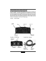
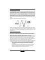
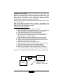
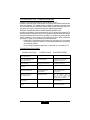
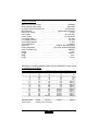
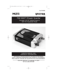
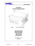
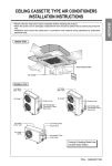
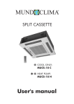
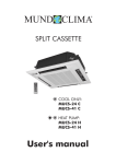
VEC550POB
POWER INVERTER 1500WATTS
SAVE THESE INSTRUCTIONS
OWNER’S MANUAL
& WARRANTY INFORMATION
THIS MANUAL CONTAINS IMPORTANT INFORMATION REGARDING SAFETY, OPERATION,
MAINTENANCE AND STORAGE OF THIS PRODUCT. BEFORE USE, READ AND UNDERSTAND
ALL CAUTIONS, WARNINGS, INSTRUCTIONS AND PRODUCT LABELS, PLUS YOUR
VEHICLE’S BATTERY MANUFACTURER GUIDELINES. FAILURE TO DO SO COULD RESULT IN
POSSIBLE INJURY OR PROPERTY DAMAGE.
4140 SW 28th Way, FT. LAUDERDALE, FL 33312
Tel 954.584.4448 • Fax 954.584.5556 • Toll Free 866.584.5504
IMPORTANT SAFETY INSTRUCTIONS
To ensure reliable service, your power inverter must be installed and used properly.
Please read all instructions thoroughly prior to use. Pay particular attention to the
WARNING and CAUTION statements in this manual. The WARNING statements
identify conditions or practices that may result in personal injury.
The CAUTION statements advise against certain conditions and practices that may
result in damage to your inverter or equipment connected to it. Save, read and
understand all instructions before using this power inverter.
WARNINGS - to reduce the risk of fire, electric shock, explosion or injury:
1. DO NOT locate inverters in an area, room or compartment where explosive or flammable fumes might be present.
2. Do not connect to AC distribution wiring - for direct plug-in use by AC appliances. 3. Remove appliance plug from outlet or turn off inverter before working on the
appliance
4. Inverter produces 120 volts, 60 Hz AC 5. Outlets are live. Risk of electric shock. Disconnect DC power before servicing.
6. Not approved for marine applications.
CAUTIONS:
1. No user-serviceable components inside. opening unit will void warranty.
2.
3.
4.
5.
6.
7.
Do not use with positive ground electrical systems (the majority of modern
automobiles, RVs, and trucks are negative ground) Reverse polarity connection will result in a blown fuse may cause permanent damage to the inverter and will void the warranty
This inverter will not operate high wattage appliances (more than 1500watts) or equipment that produce heat, such as hair dryers,
microwave ovens and toasters.
Do not operate this inverter if it is wet
Do not place in engine compartment - keep well ventilated
Not approved for use with medical equipment
Bonding between enclosure connections is not automatic and must be provided as part of the installation.
To avoid possible dangerous conditions, the inverters must be located where:
1. The unit is kept dry.
2. Air temperature is between 30 degree F (-1 degree C) non-condensing,
and 105 degrees F (40 degrees C).
3. At least three inches of clearance from other objects is maintained for
cooling airflow.
4. The unit is not exposed to direct heat or sunlight or to explosive or
flammable fumes.
2
INTRODUCTION
Power on Board Power Inverters are geared for maintaining today's modern life while
traveling in Vans, RVs, automobiles, trucks, or vehicle that has 12 volt battery power
supply and a means to recharge those batteries. This Maxx 1500 Inverter is supplied
with:
1. On/Off switch 2. Triple Outlet
3. Dual LED indicators that indicate operation (POWER), shutdown (FAULT).
4. Cooling fan 5. A grounding terminal for electrical safety. 6. DC cable connectors 7. Internal protective circuits that include:
• Automatic overload and over-temperature shutdown (activated if AC
output exceeds maximum power)
• Automatic AC short-circuit shutdown . RED FAULT LED lit.
• Automatic low voltage audible alarm.
• Automatic low-voltage shutdown.
• Automatic high-input voltage shutdown. Maxx1500 Series - is a state-of-the art, highly efficient DC to AC power inverter that
changes 12 volts DC from a battery to 120 volts AC, 60 Hz. With proper DC power,
it can continuously deliver up to 1500 watts AC. All Power on Board inverters have two methods of preventing batteries from being
completely discharged. When your batteries begin to drop in voltage, the inverter
will sound an alarm. You can either turn off the inverter or leave it unattended.
Further discharge will automatically turn off the inverter. If your battery does go to
complete discharge, it's because some other appliances are drawing power from
the battery.
This Power Inverter is configured with the latest soft start technology (SST) to
improve inverter operation. Before introduction of soft-start, high startup currents
from large inductive loads could shut down the inverter. Three major features are
incorporated in SST. First, gradual output voltage ramp-up during inverter startup.
This eliminates failed cold starts under load. Second, output that momentarily dips in voltage and quickly recovers. This eliminates
most shutdowns from momentary overloads. This power inverter also incorporates a new cooling technology that directly benefits
our customers. The new design more efficiently cools the power transistors and combined with soft start dramatically increases reliability and the life of the product.
3
TOUR OF MAXX 1500 - SERIES INVERTER
AC power is supplied via three North American, household-type receptacles as
shown in FIGURE 1. This allows the connection and operation of most 120 VACpowered electrical and electronic appliances that use a standard plug. The rest of
the front panel items are: One FAULT LED. When this lights, the inverter is shut
down. One POWER LED that lights when the inverter is operating. One ON/OFF
switch that shuts off all inverter functions. The ON/OFF switch can also be used to
reset the inverter after the inverter shutsdown due to a fault condition such as
overload, over temperature, short circuit or high voltage.
FIGURE 1 - FRONT PANEL
POWER METER
AC
OUTLET
POWER LED
(Green)
FAULT LED
(Red)
ON/OFF
SWITCH
MOUNTING
BRACKETS
MOUNTING
BRACKETS
FIGURES 2A - SIDE VIEW
NEGATIVE(-)
TERMINAL
GROUNDING
TERMINAL
FIGURES 2B - CABLES
FANS
POSITIVE
(+) TERMINAL
DC INVERTER
TERMINAL
CONNECTIONS
4
RING
TERMINALS
TO DC
BATTERY
THEORY OF OPERATION
The inverter changes 12 VDC into 120 VAC (120 VAC RMS), electrical power. This
is accomplished in two stages. The first stage raises the 12 VDC input to 145 VDC
through modern high-frequency conversion techniques. The output stage changes
the 145-VDC to 120 VAC. The inverter's output stage uses multiple banks of metaloxide semiconductor field-effect transistors (MOSFETs) to alternately apply
opposite polarity to the AC outlet's HOT and NEUTRAL terminals. The AC output
approximates a sine wave in shape. This is called Modified Sine Wave (MSW) and
it has the same energy characteristics as the sine wave of commercial electrical
power. FIGURE 3 - SINE WAVE AND MSW COMPARISON
110/120V AC
110/120V AC
NOTE: A TRUE RMS voltmeter must be used for measuring MSW. If the output of
the inverter is measured using standard digital or analog voltmeters, these
instruments may not correctly read the voltage. They typically will read from 10 to
20 volts low.
AC APPLIANCE CAUTIONS:
DO NOT plug small appliances into the inverter receptacles to directly recharge their
nickel-cadmium batteries. Always use the recharger provided with that appliance. Do NOT plug in battery chargers for cordless power tools if the charger carries a
warning that dangerous voltages are present at the battery terminals. Not all fluorescent lamps operate properly with this type of inverter. If the bulb
appears to be too bright, or fails to light, do not use the lamp with this inverter. Fans with synchronous motors may slightly increase in speed (RPM) when
powered by the inverter. This is not harmful to the fan or to the inverter. Certain chargers for small nickel-cadmium batteries can be damaged if plugged into
the inverters. In particular, two types of appliances are susceptible to damage:
• Small, battery-operated appliances such as flashlights, cordless razors and tooth brushes that can be plugged directly into an AC receptacle to recharge
• Certain battery chargers for battery packs that are used in some cordless
hand-tools. Chargers for these tools have a warning label stating that dangerous voltages are present at the battery terminals
5
DO Not use inverters with the above types of equipment. The majority of portable
appliances do not have this problem. Most portable appliances use separate
transformers or chargers that plug into AC receptacles to supply a low-voltage DC
or AC output to the appliance. If the appliance label states that the charger or
adapter produces a low-voltage DC or AC output (30 volts or less), there should be
no problem powering that charger or adapter.
Check operating temperature of small motors. If the motor operates at much higher
than normal temperature there may be an incompatibility problem. Discontinue use
and compare temperatures while operating the appliance from commercial AC power.
INVERTER APPLICATIONS
MAXX 1500 Series Inverters are ideal for powering:
• 3/8” Reversible Drill . . . . . . . . . . . . . . . . . . . . . . . . . . . . 420 watts
• Household Food Processor . . . . . . . . . . . . . . . . . . . . . . 430 watts
• Computer And Monitor . . . . . . . . . . . . . . . . . . . . . . . . . . 450 watts
• Electric Garden Tools . . . . . . . . . . . . . . . . . . . . . . . . . . . 475 watts
• Portable Vacuum . . . . . . . . . . . . . . . . . . . . . . . . . . . . . . 525 watts
• Coffee Maker . . . . . . . . . . . . . . . . . . . . . . . . . . . . . . . . . 600 watts
• 1/2” Reversible Drill . . . . . . . . . . . . . . . . . . . . . . . . . . . . 620 watts
• Reciprocating Saw . . . . . . . . . . . . . . . . . . . . . . . . . . . . . 720 watts
• 1/3“ Submersible Pump . . . . . . . . . . . . . . . . . . . . . . . . . 920 watts
• Mini Microwave. . . . . . . . . . . . . . . . . . . . . . . . . . . . . . . 1000 watts
• Chest Freezer. . . . . . . . . . . . . . . . . . . . . . . . . . . . . . . . 1200 watts
• Full-Sized Microwave Oven . . . . . . . . . . . . . . . . . . . . . 1400 watts
NOTE: APPLIANCE SPECIFICATIONS MAY VARY FROM BRAND TO BRAND. THIS
TABLE IS OFFERED ONLY AS A GUIDE TO APPROXIMATE POWER RATINGS.
CHECK APPLIANCE MANUALS OR PRODUCT LABELING FOR ACTUAL RATINGS.
TO ESTIMATE THE POWER CONSUMPTION OF APPLIANCE MULTIPLY CURRENT
RATING OF APPLIANCE BY 120VAC. TO USE THE MAXIMUM OUTPUT OF
1500WATTS, MAXX 1500 MODELS MUST BE CONNECTED TO A DC POWER
SUPPLY CAPABLE OF CONTINUOUSLY PROVIDING 150 OR MORE AMPS.
OPERATION WITH AC APPLIANCES
Turn On the inverter using the ON/Off Switch and observe that the indicators are in
the following condition:
POWER LED is lit. Plug in the appliance and turn it on, it should operate normally. NOTES: Ensure that the total continuous power consumption of all tools and/or
appliances connected to the inverter (and in use) does not exceed 1500watts. If a motorized appliance immediately shuts down, and the FAULT LED is lit, try
rocking the On/Off switch back and forth a few times while the appliance is plugged
in and turned on. See Trouble shooting section if this does not work.
6
DC CONNECTION PRECAUTIONS
IMPORTANT CABLE INFORMATION
Use cable information in Appendix A for determining gauge of cable.
Use DC Inverter terminal connections on cable ends. The user must maintain secure, tight, electrical connections. Use correct gauge DC cabling to supply up to 150 amps, or maximum load. Keep cabling short to avoid voltage drop and reduced operating time. Inverters are supplied with a grounding terminal. Connect an insulated AWG 12 wire
to this terminal and connect the other end to a solid electrical ground. This is an
important safety wire that ensures proper grounding. DO NOT CONNECT THIS
WIRE DIRECTLY TO THE NEGATIVE DC INPUT TERMINAL OF THE INVERTER,
or Battery. At full 1500 watt load, the DC input requirements are up to 150 amperes at 12 volts
DC. For most continuous-duty applications, multiple battery configuration and the
use of deep-cycle batteries is a requirement. With vehicles using multiple batteries,
inverters should be operated from one of the vehicles 12 volt batteries, so there's always one battery with adequate charge to start an engine.
LOCATION CAUTIONS:
To avoid possible dangerous conditions, the inverters must be located where:
1. The unit is kept dry.
2. Air temperature is between 30 degree F (-1 degree C) non-condensing,
and 105 degrees F (40 degrees C).
3. At least three inches of clearance from other objects is maintained for
cooling airflow.
4. The unit is not exposed to direct heat or sunlight or to explosive or flammable fumes.
5. The unit is as close to the DC power source as possible.
7
DETERMINING BATTERY CAPACITY FOR EXTENDED RUN TIMES.
Inverters must be supplied with a constant source of high current 12 volt DC from a
battery or bank of batteries. To determine the minimum battery size that you will
need to operate appliances from the inverter without a generator or alternator
charging the battery, follow these steps:
1. Determine the wattage of each appliance and/or tool you will need to
simultaneously operate from the inverter. Read the labels on the
equipment to be operated. Usually, power consumption is shown in watts.
If it is shown in amps, multiply by 120VAC to determine wattage.
2. Estimate the number of hours the equipment will be in use between battery
recharges.
3. To determine the total watt-hours of energy use, multiply the total running
time, by the average power consumption. To get an estimate of the current
(in amps) that the battery must be capable of delivering, divide the watt
hours by ten (10). Example: 250 watts for one hour is 250 watt-hours. Then
250 divided by 10 is 25 amp hours. Generally, battery capacity should be
rated at least twice the calculated amp hours.
MOUNTING THE INVERTER
The inverter should be mounted and close to the battery supply as safe from engine
fumes, explosive gas, and high temperatures. The inverter must have nonrestrictive airflow to maintain adequate cooling. Use appropriate screws or other means to fasten the inverter to a shelf, floor, wall, etc. Make sure that no damage results to fuel
or electrical lines that may be behind any sheet metal surfaces. After mounting the inverter, carefully follow the cable path to the battery by using the length of string.
Using the measurement from the string, add 6” to the end of each cable. Inverters
should be mounted horizontly not vertically.
CONNECTING TO DC SUPPLY
CAUTION: Ensure that DC connection polarity is correct. Reversed polarity will blow a fuse and
may cause permanent damage to the inverter. The manufacturer's warranty does
NOT cover damage due to reversed polarity. Review Figure 2, if necessary, to identify the location of the DC terminals and their polarities.
WARNINGS: DIRECT CONNECTION OF THE POS CABLE TO THE POS BATTERY
TERMINAL MUST BE PROTECTED AGAINST SHORT CIRCUITS. FOR THIS
INVERTER USE AN 300 ANL FUSE AND FUSE HOLDER.
8
WARNINGS CONTINUED: DANGER OF EXPLOSION. BATTERY CHARGING, DISCHARGING AND
ENGINE OPERATION PRODUCE EXPLOSIVE GASSES. MAKE SURE THE
AREA AROUND THE BATTERY IS WELL VENTILATED AND NO BATTERY
CHARGING IS OCCURRING. WEAR PROTECTIVE EYEWEAR WHILE
CONNECTING TO NON-SEALED LEAD ACID BATTERY. Place the inverter as close to the battery supply a practical making sure the inverter
is secure, dry, and cool.
Make sure the length and gauge of cable are correct for the installation. (See
Appendix A) Use cables that have 6” of extra length for stripping insulation and
fastening (crimping or soldering) ring terminals.
CONNECTION PROCEDURE:
1. Make sure the inverter's On/Off Switch is turned OFF.
2. Identify the Positive and negative terminals on the 12 volt DC battery and
identify the positive (+) and negative (-) terminals on the inverter. 3. Loosen the terminal screws from the terminal connections. 4. Attach the red cable terminal connecction to the Positive (POS or “+”)
terminal and the black cable terminal connection is attached to the
Negative (NEG or “-”) terminal of battery. Secure the cables by tighting the flathead screws on the terminals.
5. Remove the retaining nut and washer from the grounding terminal.
6. Carefully attach a single stranded insulated AWG 12 ground wire to the
grounding stud on the back of the inverter. 7. Replace the washer and nut on the grounding stud.
8. Connect the other end of the wire to Vehicle Chasis (non-moving engine part) or Earth Ground. See Figure 4 for connection diagram.
9. Attach the fuse holder to the red cable end close to the battery.
10. Prepare a very short AWG 4 cable with ring terminals to connect the
other end of the fuse holder to the battery POS terminal of the battery.
FIGURE 4 - THE INVERTER AND FUSE AND SAFETY WIRE CONNECTIONS
–
+
+
–
12 VOLT
BATTERY
ANL FUSE
HOLDER
AND 300 AMP
FUSE
CHASIS
9
INVERTER
GND
NOTE: DO NOT CONNECT THIS
SAFETY WIRE TO THE
NEGATIVE DC INPUT
TERMINAL OF THE INVERTER
11.
12.
13.
14.
Make the connections to the FUSE HOLDER and battery terminal Do not install fuse yet.
Connect the Negative cable ring terminal to the battery NEG terminal.
Insert the fuse into the fuse holder. There may be momentary sparking.
15. Check all connections and tighten any loose connections.
16. Turn ON the inverter and apply a test load to the AC outlets.
Any questions please contact Power on Board Technical Support at:
(954) 584-4446 EXT. 119 for professional direction.
SERVICE AND REPLACEMENT PARTS
FUSES
It is recommended but not required since there is internal fuse protection
that the user use an external inline ANL 300 fuse and fuse holder(not
supplied). The fuse holder, and the ANL-300 fuse (not supplied) can be
purchased at most electrical supply companies.It is also recommended that
an Automotive Electrician be used to install this cable. Any questions please contact Power on Board Technical Support at:
PH: 954-584-4446 • TOLL FREE: 866-584-5504 • FAX: 954-584-5556. 10
TROUBLESHOOTING - COMMON PROBLEMS
POWER TOOLS AND MICROWAVE OVENS WON'T START:
Read the information panel on each power tool carefully to accurately determine the
tool's input wattage. The wattage output is sufficient to operate most power tools
and microwave ovens but remember that the power needed to start the power tool
may be as much as 2 to 6 times its continuous wattage requirements.
"BUZZING" SOUND IN AUDIO SYSTEMS AND/OR SNOW IN TVS:
Inverters are shielded to minimize interference with TV signals. Ensure that the TV
antenna provides an adequate "snow free" signal and that the antenna cable is high
quality and shielded without the inverter operating. The problem may not be with the
inverter. However, in some cases, some interference may be visible, particularly
with weak TV signals. Try the following corrective measures:
• Position the TV and antenna further away from the inverter if it is the cause
of interference. Adjust the antenna, or use shielded cable hookup (if possible)
to an external antenna.
• Do not operate high-power appliances or tools when you are watching TV.
TROUBLESHOOTING GUIDE
TROUBLE/ INDICATION
POSSIBLE CAUSE
SUGGESTED REMEDY
No AC output - Green POWER LED
not lit - FAULT LED not lit
DC input below 10 Volts Recharge or replace battery
No AC output - Green POWER LED
not lit - FAULT LED not lit
DC Input fuse(s) blown
Investigate for short circuit, repair,
replace with same type fuse Low battery alarm sounds continuously
Bad connection or wiring, DC cable gauge not heavy enough.
Tighten all DC connections, replace
DC cable with heavier gauge
Low battery alarm sounds continuously
Low battery Recharge battery - remove load No AC output - FAULT LED lit Excessive appliance load- thermal shutdown
Reduce load-wait for inverter to cool, turn Off
Motorized power tool will not start - inverter shuts down
Excessive start-up load
With the appliance switch on, rock the inverter On/Off switch several times. If Appliance won't start then there is incompatibility
Motorized power tool operates at wrong speed
Purely inductive load
Simultaneously operate appliance with 60 watt light bulb
Snow in TV picture, buzz in speaker
Interference Separate inverter from antenna, use shielded antenna cable
11
SPECIFICATIONS
Maximum Continuous Power . . . . . . . . . . . . . . . . . . . . . . . . . . . . . . . . 1500Watts
Surge Capacity (Peak Power) . . . . . . . . . . . . . . . . . . . . . . . . . . . . . . 3000 Watts
No Load Current Draw (switch on) . . . . . . . . . . . . . . . . . . . . . . . . . 0.20 amperes
Max. Efficiency . . . . . . . . . . . . . . . . . . . . . . . . . . . . . . . Approximately 90 percent
Nominal DC Voltage . . . . . . . . . . . . . . . . . . . . . . . . . . . . . . . . . . . . . . . . . .13 VDC
Input Voltage . . . . . . . . . . . . . . . . . . . . . . . . . . . . . . . . . . . . . . . . . 10.0-15.0 VDC
Output Voltage . . . . . . . . . . . . . . . . . . . . . . . . . . . . . . . . . . . . . . . 120 VAC 60 Hz
Low Voltage Alarm . . . . . . . . . . . . . . . . . . . . . . . . . . . . . . . . . . . . . . . . . 10.6 Volts
Low Voltage Shutdown . . . . . . . . . . . . . . . . . . . . . . . . . . . . . . . . . . . . . 10.0 Volts Over Voltage shutdown . . . . . . . . . . . . . . . . . . . . . . . . . . . . . . . . . . . . . . . 15 VDC
Thermal Shutdown . . . . . . . . . . . . . . . . . . . . . . . . . . . . . . . . . . . . . . . . Protection
Wave Form . . . . . . . . . . . . . . . . . . . . . . . . . . . . . . . Modified Sine Wave (MSW)
Output Receptacles . . . . . . . . . . . . . . . . . . . . . Triple North American Standard Power Transistor Type . . . . . . . . . . . . . . . . . . . . . . . . . . . . . . . . . . . . . MOSFET
Weight . . . . . . . . . . . . . . . . . . . . . . . . . . . . . . . . . . . . . . . . . . . . . . . . . . . . 7.3 lbs. Length . . . . . . . . . . . . . . . . . . . . . . . . . . . . . . . . . . . . . . . . . . . . . . . . . . .10.825 in. Width . . . . . . . . . . . . . . . . . . . . . . . . . . . . . . . . . . . . . . . . . . . . . . . . . . . . . . . 8.5 in. Height . . . . . . . . . . . . . . . . . . . . . . . . . . . . . . . . . . . . . . . . . . . . . . . . . . . . . 3.12 in. APPENDIX A - PROPER GAUGE CABLE FOR 2-3 PERCENT DC VOLT LOSS
- 2 CONDUCTOR COPPER
MAXX™ UL SERIES INVERTER CONTINUOUS WATTAGE
LENGTH (FT)
2
4
6
8
10
12
14
16
18
20
22
24
26
28
30
Stocked ANL Fuses
ANL fuse Holder
800
#8
#6
#4
#3
#2
#1
#1
1/O
1/O
2/O
2/O
3/O
3/O
3/O
4/O
1000
#8
#4
#3
#2
#1
1/O
1/O
2/O
2/O
3/O
3/O
4/O
4/O
4/O
250mcm
ANL200
ANL200
ANLBLK (Fits all ANL Fuses)
12
1500
#6
#3
#2
1/O
2/O
2/O
3/O
4/O
4/O
250mcm
250mcm
300mcm
300mcm
350mcm
350mcm
3000
#3
1/O
2/O
4/O
250mcm
300mcm
350mcm
350mcm
400mcm
500mcm
500mcm
600mcm
600mcm
700mcm
700mcm
ANL300
ANL500
POWER ON BOARD 2 YEAR LIMITED WARRANTY PROGRAM
This limited warranty program is the only one that applies to this product, and it sets forth all the responsibilities of Power on Board Manufacturing, Ltd., regarding this product. There is no other
warranty, other than those described herein.
This Power on Board Manufacturing, Ltd. product is warranted, to the original purchaser only, to
be free of defects in materials and workmanship for two years from the date of purchase without
additional charge. The warranty does not extend to subsequent purchasers or users. Power on
Board Manufacturing, Ltd. will not be responsible for any amount of damage in excess of the retail
purchase price of the product under any circumstances. Incidental and consequential damages
are specifically excluded from coverage under this warranty.
This product is not intended for commercial use. This warranty does not apply to accessories or damage to units from misuse or incorrect installation. Misuse includes wiring or connecting to
improper polarity power sources.
RETURN/REPAIR POLICY: Defective products, other than accessories, may be returned postage
prepaid to Power on Board Manufacturing. Any defective product, other than accessories, that is
returned to Power on Board Manufacturing within 30 days of the date of purchase will be replaced
free of charge. If such a product is returned more than 30 days but less than two years from the
purchase date, Power on Board Manufacturing will repair the unit or, at its option, replace it free of
charge.
If the unit is repaired, new or reconditioned replacement parts may be used, at Power on Board
Manufacturing’s option. A unit may be replaced with a new or reconditioned unit of the same or
comparable design. The repaired or replaced unit will then be warranted under the terms of the
remainder of the warranty period. The customer is responsible for the shipping charges on all
returned items after 30 days. During the warranty period, Power on Board Manufacturing, Ltd. will
be responsible for the return shipping charges.
lIMITATIONS: This warranty does not cover accessories, bulbs, fuses and batteries, defects
resulting from normal wear and tear (including chips, scratches, abrasions, discoloration or fading
due to usage or exposure to sunlight), accidents, damage during shipping to our service facility,
alterations, unauthorized use or repair, neglect, misuse, abuse, failure to follow instructions for care
and maintenance, fire, flood and Acts of God.
If your problem is not covered by this warranty, call our Technical Support Department at (954) 584-4446 or toll free at (866) 584-5504 for general repair information and charges if applicable. STATE LAW RIGHTS: This warranty gives you specific legal rights. Some states do not allow
limitations on how long an implied warranty lasts or the exclusion or limitation of incidental or
consequential damages, so the exclusions or limitations stated herein may not apply. This warranty
gives the purchaser specific legal rights; other rights, which vary from state to state, may apply.
TO REQUEST WARRANTY SERVICE FOR THIS PRODUCT: Contact Power on Board
Manufacturing Technical Support by telephone, fax or mail. We suggest that you keep the original
packaging in case you need to ship the unit. When returning a product, include your name,
address, phone number, dated sales receipt (or copy) and a description of the reason for return
and product serial number. After repairing or replacing the unit, we will make every effort to return
it to you within four weeks.
WARRANTY ACTIVATION: Please complete Warranty Activation Card and mail to Power on
Board Manufacturing. Enter “VEC550POB” as “Model and 1500watts Power Inverter” as Product
Type. All Power on Board Manufacturing, Ltd. products must be registered within 10 days of
purchase to activate this warranty. Mail the completed registration form, along with a copy of the
original sales receipt to:
ATTN.: CUSTOMER SERVICE 4140 SW 28TH WAY, FT. LAUDERDALE, FL 33312 PH: 954-584-4446 • TOLL FREE: 866-584-5504 • FAX: 954-584-5556. WARRANTY IS NON-TRANSFERABLE AND NON-REFUNDABLE.
RD010605
13