1
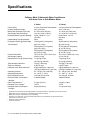
Cat. No. 01-8819-48
Revised 1/96
CULLIGAN MARK 10
AUTOMATIC WATER CONDITIONER
Installation/Operating Instructions
®
Models from 1995
WARNING: IF INCORRECTLY INSTALLED, OPERATED OR MAINTAINED, THIS PRODUCT CAN CAUSE SEVERE INJURY.
THOSE WHO INSTALL, OPERATE, OR MAINTAIN THIS PRODUCT SHOULD BE TRAINED IN ITS PROPER USE, WARNED OF
ITS DANGERS, AND SHOULD READ THE ENTIRE MANUAL BEFORE ATTEMPTING TO INSTALL,
OPERATE OR MAINTAIN THIS PRODUCT.
CULLIGAN COMPANY
NORTHBROOK, ILLINOIS 60062
©1996 Culligan International Company
Printed in USA
Attention Culligan Customer:
The installation, service and maintenance of this equipment should
be rendered by a qualified and trained service technician. Your local independently operated Culligan dealer employs trained
service and maintenance personnel who are experienced in the
installation, function and repair of Culligan equipment. This publication is written specifically for these individuals and is intended
for their use.
We encourage Culligan users to learn about Culligan products, but
we believe that product knowledge is best obtained by consulting
with your Culligan dealer. Untrained individuals who use this manual
assume the risk of any resulting property damage or
personal injury.
WARNING — Prior to servicing equipment, disconnect
power supply to prevent electrical shock.
IF THIS EQUIPMENT IS TO BE USED IN THE TREATMENT OF
DRINKING WATER, THE WATER MUST BE MICROBIOLOGICALLY SAFE.
CULLIGAN MARK 10
AUTOMATIC WATER CONDITIONERS
Installation/Operating Instructions
®
Models from 1995
Table of Contents
Specifications ........................................................... 2
Preparation ............................................................... 3
Installation ................................................................ 5
Settings .................................................................... 9
Start-Up Procedure ................................................ 14
Sanitizing Procedure .............................................. 15
Specifications
Culligan® Mark 10 Automatic Water Conditioners
with Auto Clock or Soft-Minder® Meter
Control Valve
Overall Conditioner Height
Media Tank Dimensions (Dia x Ht)
Salt Storage Tank Dimensions
Exchange Media, Type and Quantity
Underbedding Type and Quantity
Exchange Capacity @ Salt Dosage
Per Recharge1
Freeboard to Media2
Salt Storage Capacity
Rated Service Flow @ Pressure Drop
Total Hardness, Maximum
Total Iron, Maximum
Hardness to Iron Ratio, Minimum4
Operating Pressure
Operating Temperature
Electrical Requirements
Electrical Power Consumption,
Min/Max
Drain Flow, Maximum5
Recharge Time, Average6
Recharge Water Consumption,
Average6
1
2
3
4
5
6
9" Model
5-cycle, Reinforced Thermoplastic
44 in (1118 mm)
9 x 38 in (229 x 965 mm)
16 x 43 in (406 x 1092 m)
Cullex® Media, 0.7 cu ft
(20 liters)
None
15,500 grains (1 000 grams)
@ 4.0 lb (1.8 kg)
20,300 grains (1 315 grams)
@ 8.0 lb (3.6 kg)
22,500 grains (1 450 grams)
@ 12.0 lb (5.4 kg)
14.75-16.75 in (374.7-425.5 mm)
250 lb (114 kg)
7.4 gpm @ 15 psi
(29.6 lpm @ 100 kPa)
75 gpg (1 300 mg/l)
5 ppm (5 mg/l)
8 gpg Hardness to 1 ppm Iron
(140 mg/l Hardness to 1 mg/l Iron)
20 - 125 psi (140 - 860 kPa)
33 - 120°F (1 - 50°C)
120 Volts AC, 60 Hertz
3 Watts/25 Watts
12" Model
5-Cycle, Reinforced Thermoplastic
44 in (1118 mm)
12 x 38 in (305 x 965 mm)
16 x 43 in (457 x 1092 mm)
Cullex Resin, 1.4 cu ft
(40 liters)
None
28,800 grains (1 866 grams)
@ 8.0 lb (3.6 kg)
37,500 grains (2 430 grams)
@ 12.0 lb (5.4 kg)
43,600 grains (2 825 grams)
@ 16.0 lb (7.2 kg)
14.5-16.5 in (368.3-419.1 mm)
375 lb (170 kg)
7.4 gpm @ 15 psi
(31 lpm @ 100 kPa)
100 gpg (1 700 mg/l)
5 ppm (5 mg/l)
8 gpg Hardness to 1 ppm Iron
(140 mg/l Hardness to 1 mg/l Iron)
20 - 125 psi (140 - 860 kPa)
33 - 120°F (1 - 50°C)
120 Volts AC, 60 Hertz
3 Watts/25 Watts
3.4 gpm (13 lpm)
70 min
64 gal (242 liters)
3.4 gpm (13 lpm)
70 min
110 gal (416 liters)
Capacities and corresponding salt dosages pertain to low hardness waters. Capacities given are per recharge.
Measured from top of media to top of inlet fitting (backwashed and drained).
Measured from top of underbedding to top of inlet fitting.
Hardness to iron ratio does not apply and total hardness and iron specifications change as follows when
Sofner-Gard™ Accessory is used.
Backwash at 120 psi (830 kPa).
10 minute backwash.
2 / CULLIGAN MARK 10 AUTOMATIC WATER CONDITIONER
Preparation
COMPONENT DESCRIPTION
The water conditioner is shipped from the factory in one
carton. Remove all components and inspect them before
starting installation.
Control Valve Assembly - Includes the 5- cycle regeneration control valve and electronic timer assembly. A small
parts package contains installation hardware and consumer
literature, including an Owner’s Guide and warranty policy.
Media Tank - Contains the Tripl-Hull™ media tank complete with Cullex® ion exchange resin, underbedding and
outlet manifold.
Salt Storage Tank Assembly - Includes salt storage container with support plate and Dubl-Safe™ brine refill valve
and chamber.
• Threading tools, pipe wrenches and thread sealer for
threaded connections
• Saw, solvent and cement for plastic pipe connections
Materials
• Brine line, 5/16" (PN 00-3031-28 or equivalent)
• Drain line, 1/2" (PN 00-3030-82, gray, semi-flexible; or
PN 00-3319-46, black, semi-rigid; or equivalent)
• Thread sealing tape
• Pressure reducing valve (if pressure exceeds 125 psi
[860 kPa], PN 00-4009-00 or equivalent)
• Pipe and fittings suited to the type of installation
• Water softener salt (rock, solar or pellet salt formulated
specifically for water softeners)
BYPASS VALVES
A bypass valve is included with the control valve assembly.
TOOLS AND MATERIALS
APPLICATION
The following tools and supplies will be needed, depending
on installation method. Observe all applicable codes.
All Installations
•
•
•
•
Safety goggles
Phillips screwdrivers, small and medium tip
Gauge assembly (PN 00-3044-50 or equivalent)
Silicone lubricant (PN 00-4715-07 or equivalent) - DO
NOT USE PETROLEUM-BASED LUBRICANTS.
• A bucket, preferably light-colored
• Towels
Water quality - Verify that raw water hardness and iron are
within limits. Note the hardness for setting the salt dosage
and recharge frequency.
Pressure - If pressure exceeds 125 psi (860 kPa), install a
pressure reducing valve (see materials checklist). On private
water systems, make sure the minimum pressure (the pressure at which the pump starts) is greater than 20 psi
(140 kPa). Adjust the pressure switch if necessary.
CAUTION: The use of a pressure reducing valve
may limit the flow of water in the household.
Special Tools
• Torch, solder and flux for sweat copper connections
Temperature - Do not install the unit where it might freeze,
or next to a water heater or furnace or in direct sunlight.
PREPARATION / 3
LOCATION
NOTICE: Most codes require an anti-siphon device or airgap.
Space requirements - Allow 6-12 inches (15-30 cm)
behind the unit for plumbing and drain lines and 4 feet (1.3
meters) above for service access and filling the salt
container.
Electrical facilities - A 6-foot grounded cord is provided.
The customer should provide a 3-prong grounded receptacle,
preferably one not controlled by a switch that can be turned
off accidentally. Observe local electrical codes.
Floor surface - Choose an area with solid, level floor free of
bumps or irregularities. Bumps, cracks, stones and other
irregularities can cause the salt storage tank bottom to
crack when filled with salt and water.
WARNING! ELECTRICAL SHOCK HAZARD! DO
NOT REMOVE THE GROUNDING PRONG! IF THE
RECEPTACLE IS DESIGNED ONLY FOR 2-PRONG
PLUGS, OBTAIN A 3-PRONG ADAPTER AND
GROUND IT SECURELY TO THE RECEPTACLE. DO
NOT USE EXTENSION CORDS.
Drain facilities - Choose a nearby drain that can handle the
rated drain flow (floor drain, sink or stand pipe). Refer to the
Drain Line Chart, Table 1 (page ---), for maximum drain line
length.
4 / CULLIGAN® MARK 10 AUTOMATIC WATER CONDITIONER
Installation
PLACEMENT
BRINE CHAMBER ASSEMBLY
Refer to Fig. 1
• Remove the nut and screw from the brine chamber
housing.
• Set the media tank on a solid, level surface near water,
drain and electrical facilities. Place the outlet (black coupling) of the tank on the left.
• Locate the hole in the recess of the brine tank. Place the
screw through this hole.
• Set the brine system on a flat, smooth, solid surface as
near the media tank as possible.
• Line up the hole in the brine chamber with the screw. Place
the brine chamber onto the screw and secure with the nut.
FIG. 1
INSTALLATION
/5
• Place brine valve into the chamber. The top of the valve
should rest within the groove of the brine chamber.
CAUTION: Close the inlet supply line and
relieve system pressure before cutting into the
plumbing! Flooding could result!
MOUNT THE CONTROL VALVE
See Fig. 2.
• Remove and discard the protective covers on the tank
couplings.
CAUTION: When making sweat connections, remove all plastic and rubber components which contact brass or copper. Damage to these components may result otherwise.
BYPASS VALVE INSTALLATION
• Position the light colored tank coupling to the right. This
is the inlet side of the tank.
WARNING: FAILURE TO PROPERLY POSITION
TANK WILL RESULT IN LOSS OF MEDIA.
The bypass valve connects directly to the backplate of the
valve with a pair of screws (Fig. 3). Use a long standard
screw driver to facilitate installation. Lubricate all o-rings
with silicon lubricant.
• Lubricate the o-rings on the tank couplings with silicon
lubricant.
BYPASS VALVE INSTALLATION
(SOFT-MINDER® METER ONLY):
• Place the control on the tank couplings and press down
firmly.
The Soft-Minder meter is placed between the bypass valve
and the control (Fig. 4). Make sure the meter is on the outlet
• Install the u-clamps on both sides of the control and secure
with the screws.
PLUMBING CONNECTIONS
Two methods of connecting the water softener to the plumbing system are available. Shipped with each softener is a
Culligan ® Cul-Flo-Valv ® bypass valve, either PN
00-3314-42 or 00-3314-46. If local conditions warrant, you
may use the sweat adaptor kits, PN 00-3314-44 or
00-3314-45.
NOTICE: The Soft-Minder® meter cannot be used with the
sweat adaptors.
FIG. 3
FIG. 2
6 / CULLIGAN® MARK 10 AUTOMATIC WATER CONDITIONER
port of the control. A pair of elongated bolts are packaged
with the meter to hold the bypass valve to the back plate of
the control. Lubricate all o-rings with silicon lubricant.
drain line length and height limitations, and to Fig. 6.
SWEAT ADAPTOR INSTALLATION
• Route a length of 1/2" drain line from the drain elbow to
the drain.
The seat adaptors use a snap ring to hold them to the backplate
of the control valve. The back plate will need to be removed
from the valve for this connection. A pair of snap ring pliers,
PN 00-5916-09, are needed for this connection.
CONNECT THE BRINE LINE
• Remove 1/2" pipe clamp from end of drain elbow.
• Fasten the drain line to the elbow with the clamp.
• Secure the drain line to the drain to prevent its movement
during regeneration. A loop in the end of the tube will
keep it filled with water and will reduce splashing at the
beginning of each regeneration.
Refer to Fig. 5.
• Measure a length of brine line sufficient to reach from the
brine tank to the brine fitting and then add four feet (1.3
meters). Cut both ends squarely and cleanly.
NOTICE: Observe all plumbing codes. most codes require
an anti-siphon device or air gap at the discharge point!
FILL THE SALT STORAGE CONTAINER
• Remove the brine valve from the brine tank and remove
the white nut and insert. Return float rod to its original
position.
Fill the salt storage container with water until the level reaches
about 1 inch above the salt support plate. Pour salt into the
container. Fill to within a few inches of the top.
• Slip the white nut over one end of the tubing and press the
plastic insert into the end of the tubing. Connect to the
brine valve and tighten nut.
SOFT-MINDER® METER CONNECTIONS
• Remove white nut and insert from the brine elbow
assembly.
• Remove the timer case by grasping the front cover and
pulling outward.
• Slip the white nut over one end of the tubing and press the
plastic insert into the end of the tubing. Connect to the
brine connection on the valve and tighten nut.
• Remove the screw from the protective cover and remove
cover.
To connect meter leads, proceed as follows:
DRAIN LINE CONNECTION
Refer to Table 1, page 11, under the applicable tank size for
CAUTION: Do not allow the timer case to hang
from the wires. Damage to the wires and/or terminals may result.
FIG. 4
FIG. 5
INSTALLATION
/7
• Locate the 1/2" hole in the lower right hand corner of the
timer plate.
• Slip the meter cable through the hole and toward the
circuit board.
• Connect the lead to the circuit board at the upper most
portion of the lower set of terminal pins. Make sure the
cord lays across the circuit board.
• Locate the strain relief bushing in the parts pack. Place it
on the cable at the point of entry to the rear of the timer
plate and push it into the hole.
FIG. 6
TABLE 1
9-INCH MODELS
Average Water
Pressure
psi
kPa
30
2.1
50
3.5
70
4.8
4 in.
0.1m
56
17.1
112
34.2
143
43.6
1 ft
0.3m
50
15.3
106
32.3
137
41.8
2 ft
0.6m
40
12.2
96
29.3
127
38.7
3 ft
0.9m
30
9.2
86
26.2
117
35.7
4 ft
1.2m
20
6.1
76
23.2
107
32.6
5 ft
1.5m
10
3.1
66
20.1
97
29.6
6 ft
1.8m
7 ft
2.1m
8 ft
2.4m
9 ft
2.7m
10 ft
3.1m
56
17.1
87
26.5
46
14.0
77
23.5
36
11.0
16
4.9
67
20.4
26
7.9
57
17.4
47
14.3
90
6.2
120
8.3
153
46.7
159
48.5
147
44.8
153
46.7
137
41.8
143
43.6
127
38.7
133
40.6
117
35.7
123
37.5
107
32.6
113
34.5
97
29.6
103
31.4
87
26.5
93
38.4
77
23.5
83
25.3
67
20.4
73
22.3
57
17.4
63
19.2
Height of Drain Discharge Above Floor Upon Which Softener Sets
12-INCH MODELS
Average Water
Pressure
psi
kPa
30
2.1
50
3.5
70
4.8
0.3 ft
0.1m
44
13.4
103
31.4
129
39.3
1 ft
0.3m
38
11.6
97
29.6
123
37.5
2 ft
0.6m
28
8.5
87
26.5
113
34.5
3 ft
0.9m
18
5.5
77
23.5
103
31.4
4 ft
1.2m
5 ft
1.5m
6 ft
1.8m
7 ft
2.1m
8 ft
2.4m
9 ft
2.7m
10 ft
3.1m
67
20.4
47
14.3
73
22.3
37
11.3
63
19.2
27
8.2
93
28.4
57
17.4
83
25.3
53
16.2
17
5.2
43
13.1
7
2.1
33
10.1
90
6.2
120
8.3
145
44.2
153
46.7
139
42.4
147
44.8
129
39.3
137
41.8
119
36.3
127
38.7
109
33.2
117
35.7
99
30.2
107
32.6
89
27.1
97
29.6
79
24.1
87
26.5
69
21.0
77
23.5
59
18.0
67
20.4
49
14.9
57
17.4
Height of Drain Discharge Above Floor Upon Which Softener Sets
8 / CULLIGAN® MARK 10 AUTOMATIC WATER CONDITIONER
Settings
Before the unit can be recharged and put into service, several
settings must be made.
BACKWASH
Backwash, the first step in the recharge cycle, expands and
loosens the resin bed, and flushes away accumulated turbidity. The backwash interval is preset at the factory for 10
minutes which is adequate for most water supplies. It is
adjustable, however, for 5 to 30 minutes. It is recommended
that backwash last just long enough so that the effluent from
the drain line is clear. Backwash too long and water is wasted,
not long enough and the tank becomes fouled with sediment.
TIME OF RECHARGE
The timer is factory-set to recharge at 2:00 a.m. (plus or
minus 20 minutes), a timer when water usage is at a minimum for most families. If water is used during recharge,
hard water will be automatically bypassed to service. If it
would be more convenient to have the water conditioner
recharge at a different time of day the setting may be changed
as follows, referring to Fig. 8.
1. The position of the time-of-day dial (E) in relation to the
peg (D) on the black tab determines when the conditioner
will begin to recharge.
2. Remove the set screw (M).
If backwash time adjustment is needed, see Fig. 17. THE
TIMER MUST BE DISCONNECTED FROM THE POWER
SUPPLY WHEN MAKING INTERNAL ADJUSTMENTS.
1. Remove the timer from the case and turn it over to view
the fiber electrical barrier.
3. Lift the white time-of-day dial and rotate it until the
desired time of recharge is opposite the peg (D). Please
note that whenever the time of recharge is changed, the
time-of-day setting must be changed also.
4. Replace set screen.
2. Loosen both the screw holding the barrier in place and
rotate the barrier to expose the cams and switches.
3. Refer to Fig. 7. Loosen screw (A) and rotate the black
cam segment (B) until its pointer indicates the desired
backwash time on the grey cam segment (C). Retighten
screw (A).
4. Replace the fiber barrier and tighten the screws.
All normal adjustments from this point on may be made with
the timer mechanism securely fastened within its case. The
unit may be plugged in at this time.
FIG. 7
SETTINGS
/9
FIG. 8
TIME OF DAY
Upon completing the installation, the timer must be set to
the correct time of day. Time of day must also be reset after
any kind of power interruption, such as that caused by an
electrical storm. See Fig. 8.
1. Determine the correct time of day.
2. Grasp the gear (F) and lift straight up (the white time-ofday dial will lift with it). Rotate the dial until the correct
time of day lines up with the pointer (G). The dial is springloaded and will return to its position when released. Make
sure the teeth mesh.
Note that the silver half of the time-of-day dial designates
the daytime hours, while the black half designates the nighttime hours.
SERVICE POSITION
The timer assembly is in the service position when the toothless notch in the cam gear (J) is over the teeth on the idler
gear (H). The timer will return to this position after each
recharge (Fig. 8).
FIG. 9
2. The total hardness of the water as shown on the Culligan
Water Analysis Report.
With these factors known, refer to Salt Dosage/Frequency
Charts, Table 2A/2B. Find the box in the right or left column
with the number of individuals in the household, or the approximate daily average water usage. Move across until the
box under the correct hardness range is reached. The number
in the shaded portion of the box indicates the amount of salt,
in pounds (kilograms), to be used for each recharge, and the
number in the non-shaded portion indicates the number or
recharges required per six-day period.
NOTICE: The optional 7-day frequency wheel may be used
when recharge is desired only on specific days of the week.
As an example, if four individuals live in the household, and
the water has a total hardness of 18 grains per gallon, the salt
dosage per recharge for the water conditioner will be 5 pounds
(2.5 kg) and the recharge frequency will be 3 (or every 2
days). Monthly salt usage can be estimated, using these
figures, at about 75 pounds (37.5 kg).
SALT DOSAGE SETTING
Set the salt dosage as follows, referring to Fig. 9.
SALT DOSAGE/RECHARGE FREQUENCY
(Time Clock Models Only)
The salt dosage is the number of pounds of salt the softener
will use with each recharge. The frequency is the number of
recharges per six day period (or seven day period, with
optional 7-day frequency wheel).
1. Loosen screw (I).
2. Grasp the gear (L) and rotate the salt dosage dial until the
desired dosage is indicated by the point (K).
3. Retighten screw (I).
To determine the salt dosage and frequency, two things must
be known:
FREQUENCY (Time Clock Models Only)
1. Daily water usage as determined by the number of
persons in the household or by actual gallonage measurements.
Starting with all pins in the up position, set the correct frequency on the frequency wheel by pushing down the appropriate number of pins. Refer to Tables 5A and 5B.
10 / CULLIGAN® MARK 10 AUTOMATIC WATER CONDITIONER
GALLONS SETTING (Soft-Minder® Models Only)
Determine the daily water use for the household. Usually
75-100 gallons per day per person is adequate. Using Tables
2A and 2B, locate the hardness range for your water supply.
Move down the column and locate the gallons setting and
salt dosage which best suits the application. Usually two to
three days between regenerations yields the best results. Allow for one half to one days water usage as reserve capacity. Set the salt dosage per the instructions on page 10.
1. Rotate the frequency wheel (O) until the pin beneath the
number 1 is opposite the peg on the manual recharge
lever (N).
2. Refer to Table 3 and push down the pins under the
numbers indicated.
If using the optional 7-day frequency wheel, assign a number to each day of the week. For example, 1-Sunday, 2-Monday, 3-Tuesday, and so on. Line up the number corresponding to the present day of the week and push down only those
pins corresponding to the days upon which you want the unit
to recharge. All remaining pins must be in the up position.
The gallons are set with the dip switches located on the board.
Refer to Table 4 for the proper positioning of the switches.
Dip switch number 1 should be set to the R (run) position.
TABLE 2A - CULLIGAN® MARK 10 GALLON CAPACITIES TO SIGNAL (RESERVE), 9" MODEL
TOTAL WATER HARDNESS IN GRAINS PER GALLON (mg/L)
SALT
DOSAGE
0-10
(0-170)
4
900
(173)
1200
(570)
1200
(776)
1200
(940)
1600
(682)
1600
(807)
1600
(919)
2000
(620)
2000
(680)
5
6
7
8
9
10
11
12
61-75
11-20
21-30
31-40
41-50
51-60
(171-340) (341-515) (516-685) (686-855) (856-1025) (1026-1280)
600
(173)
600
(285)
600
(388)
600
(470)
900
(241)
900
(304)
900
(360)
900
(410)
900
(440)
300
(215)
300
(290)
300
(359)
600
(113)
600
(161)
600
(202)
600
(240)
600
(273)
600
(293)
NA
300
(143)
300
(194)
300
(235)
300
(271)
300
(302)
300
(330)
300
(355)
300
(370)
NA
NA
NA
NA
NA
NA
NA
NA
NA
NA
NA
NA
NA
NA
NA
NA
NA
300
(128)
300
(156)
300
(181)
300
(204)
300
(224)
300
(236)
300
(137)
300
(147)
NA
NA
TABLE 2B - CULLIGAN® MARK 10 GALLON CAPACITIES TO SIGNAL (RESERVE), 12" MODEL
TOTAL WATER HARDNESS IN GRAINS PER GALLON (mg/L)
SALT
DOSAGE
0-10
(0-170)
6
1600
(782)
2000
(647)
2000
(877)
2500
(581)
2500
(762)
2500
(927)
2500
(1077)
2500
(1215)
3000
(842)
3000
(961)
3000
(1072)
3000
(1177)
3000
(1276)
7
8
9
10
11
12
13
14
15
16
17
18
11-20
21-30
31-40
41-50
51-60
61-70
71-80
81-90
91-100
(171-340) (341-515) (516-685) (686-855) (856-1025) (1026-1200) (1201-1370) (1371-1540) (1541-1700)
900
(291)
900
(424)
900
(539)
1200
(340)
1200
(431)
1200
(513)
1200
(588)
1200
(657)
1600
(321)
1600
(381)
600
(436)
1600
(488)
1600
(538)
600
(194)
600
(282)
600
(359)
600
(427)
900
(187)
900
(242)
900
(292)
900
(338)
900
(381)
900
(420)
900
(457)
900
(492)
1200
(225)
300
(295)
300
(362)
600
(119)
600
(170)
600
(216)
600
(257)
600
(294)
600
(329)
600
(361)
600
(390)
600
(418)
900
(144)
900
(169)
300
(176)
300
(229)
300
(275)
300
(316)
300
(352)
300
(385)
600
(115)
600
(143)
600
(168)
600
(192)
600
(214)
600
(235)
600
(255)
NA
300
(141)
300
(180)
300
(213)
300
(244)
300
(271)
300
(296)
300
(319)
300
(340)
300
(360)
300
(379)
300
(396)
600
(113)
NA
NA
NA
NA
NA
NA
NA
NA
NA
NA
NA
NA
NA
NA
NA
NA
NA
NA
NA
NA
NA
NA
NA
NA
NA
NA
NA
300
(140)
300
(166)
300
(190)
300
(211)
300
(231)
300
(249)
300
(266)
300
(282)
300
(297)
300
(311)
300
(147)
300
(164)
300
(180)
300
(195)
300
(209)
300
(222)
300
(234)
300
(140)
300
(152)
300
(164)
300
(175)
NA
NA
NA
300
(128)
SETTINGS
/ 11
TABLE 3 - A DIMENSION CHART
Salt Dosage
(Pounds)
3
4
5
6
7
8
9
10
11
12
13
14
15
16
17
18
19
20
250 lb.
Brine Tank
A Dimension
inches (mm)
3-1/4
4-5/8
6
7-3/8
8-3/4
9-1/4
11-5/8
12-7/8
14-1/2
15-3/4
17-1/4
18-1/2
19-7/8
21-1/4
22-3/4
24-1/2
25-1/2
26-7/8
TABLE 4 - REGENERATION SCHEDULE
375 lb.
Brine Tank
A Dimension
inches (mm)
(83)
(117)
(152)
(187)
(222)
(235)
(295)
(327)
(368)
(400)
(438)
(470)
(505)
(540)
(578)
(622)
(648)
(683)
—
3-1/2
4-1/2
5-1/2
6-1/2
7-1/2
8-1/2
9-3/8
10-3/8
11-3/8
12-3/8
13-3/8
14-3/8
15-3/8
16-3/8
17-1/4
18-1/4
19-1/4
SWITCH POSITION
(89)
(114)
(140)
(165)
(191)
(216)
(238)
(264)
(289)
(314)
(340)
(365)
(391)
(416)
(438)
(464)
(489)
CAPACITY (GAL.)
SW2
SW3
SW4
300
600
900
1200
1600
2000
2500
3000
ON
ON
ON
ON
OFF
OFF
OFF
OFF
ON
ON
OFF
OFF
ON
ON
OFF
OFF
ON
OFF
ON
OFF
ON
OFF
ON
OFF
EXTRA RECHARGE
An extra recharge may be initiated at any time by moving the
manual recharge lever (F) fully to the left, then release. On
Aqua-Sensor® models, the demand button, must also be depressed momentarily. The timer will complete the cycle automatically and, on timeclock models, recharge again the next
regularly scheduled recharge time. Sensor models will not
recharge again until the sensor detects the need. An extra
recharge should not be initiated 2 to 3 hours before a scheduled recharge is to take place.
TABLE 5A - CULLIGAN® MARK 10, 9" MODEL SALT DOSAGE - FREQUENCY
Total Water Hardness In Grains Per Gallon (mg/L)
Persons in
Household
0-10
11-20
21-30
31-40
41-50
51-60
61-75
Gallons (liters)
(0-170) (171-340) (341-515) (516-685) (686-855) (856-1025) (1026-1280) of Water Per Day
2
4
3
5
4
8
5
4
6
5
7
5
8
8
9
5
10
6
4
4
6
13
1
1
1
2
2
2
2
3
3
6
8
5
4
6
4
4
4
5
6
11
1
2
3
3
6
6
6
5
5
4
4
5
7
9
2
3
6
6
6
6
6
4
4
5
6
9
11
3
6
6
6
7
6
7
9
3
6
6
6
11
9
11
3
6
6
11
11
6
150 (570)
6
225 (850)
300 (1135)
375 (1420)
6
450 (1705)
6
525 (1990)
600 (2270)
6
675 (2555)
6
750 (2840)
6
1000 (3785)
6
1300 (4920)
6
1600 (6055)
6
2100 (7950)
NOTE: The salt dosage and recharge frequencies in Tables 5A and 5B are intended for reference purposes
only. Actual experience with the water you are treating will dictate the optimum salt dosage and recharge
frequency that will provide efficient system operation.
12 / CULLIGAN® MARK 10 AUTOMATIC WATER CONDITIONER
TABLE 5B - CULLIGAN® MARK 10, 12" MODEL SALT DOSAGE - FREQUENCY
Total Water Hardness In Grains Per Gallon (mg/L)
*Persons in
Household
0-10
11-20
21-30
31-40
41-50
51-60
61-70
71-80
81-90
91-100
Gallons (liters)
(0-170) (171-340) (341-515) (516-685) (686-855) (856-1025) (1026-1200) (1201-1370) (1371-1540) (1541-1700) of Water Per Day
2
9
UNIT IS
OVERSIZED
USE
MARK 10, 9"
3
4
6
6
5
6
7
8
7
5
8
5
9
6
10
7
7
8
7
9
11
13
15
20
1
2
2
2
2
2
2
6
6
5
6
6
8
9
12
8
12
20
3
3
3
3
3
3
6
9
6
6
6
7
8
12
1
2
3
3
3
6
6
6
6
6
7
7
8
5
7
8
8
11
12
15
2
3
3
6
6
6
6
6
6
6
9
6
7
9
12
13
16
20
3
8
3
13
6
8
6
10
6
13
6
16
6
20
3
11
3
6
6
6
6
7
11
14
18
20
3
6
6
6
6
12
10
12
18
20
3
6
6
6
9
11
17
20
6
6
6
6
6
6
9
14
20
6
150 (570)
6
225 (850)
6
300 (1135)
375 (1420)
450 (1705)
525 (1990)
6
600 (2270)
6
675 (2555)
6
750 (2840)
6
825 (3120
6
1000 (3785)
6
1500 (5685)
6
2000 (7570)
6
2500 (9460)
6
3000 (11355)
6
3500 (11250)
6
4000 (15140)
*In household application, not recommended for over 10 people because of pressure drop limitations. Gallons are listed up to 4000 gallons/
day (15 140 liters/day) for other uses.
TABLE 6 - RECHARGE FREQUENCY
No. Down on
Salt Chart
Tab. No. Down on
Frequency Dial
Recharge
Frequency
1
1
Every six days
2
1&4
Every three days
3
1, 3 & 5
Every other day
6
All Pins
Every day
SETTINGS
/ 13
Start-Up Procedure
NOTICE: A sanitizing agent has been added to the conditioner tank at the factory. This sanitizing agent must be flushed
out before the unit is placed into service by initiating a
recharge using the steps outlined below.
1. With the timer in the service position, connect the threewire power cord to an appropriate grounded electrical
outlet. If a three-wire outlet is not available, purchase a
“three-prong to two-prong adapter” from your local hardware store. The ground wire from the adapter should be
affixed to the outlet box or plate.
2. Set the timer to the correct time of day, time of recharge,
frequency of recharge, and refill regulator assembly to
the proper number.
3. With the unit in the service position, slowly open the
inlet valve or slowly push the blue knob of the
Cul-Flo-Valv® bypass. Allow water to fill the tank.
4. Turn the water off. Rotate the cam with the salt dosage
dial one third turn. Slowly open the valve. For units
equipped with the Soft-Minder® meter, push the red
button on the timer mechanism.
14 / CULLIGAN® MARK 10 AUTOMATIC WATER CONDITIONER
5. Rotate the salt dosage cam until the notch in the gear is
over the idler gear (see page 10, Service Position). A
manual regeneration should be initiated at this time.
6. To allow the customer to enjoy the benefits of soft water
at this time, it is advisable to drain the hot water tank of
the hard water and allow it to be refilled with soft water.
Otherwise, because of the capacity of the hot water tank,
it may take two or three days to displace the hard water
with soft water in the hot water tank.
7. Explain to the customer the operation of the bypass
valve(s) and make sure that the customer knows that there
will be new sounds associated with the recharging and
operating of the unit.
8. Advise the customer to periodically check and replenish
the salt supply.
9. Clean up the unit and the installation site, removing any
soldering or pipe threading residues from the equipment
with a damp towel.
Sanitizing Procedure
A water softener in daily use on a potable water supply generally requires no special attention other than keeping the
salt tank filled. Occasionally, however, a unit may require
sanitation under one of the following conditions:
• The unit has stood idle for a week or more (the premises
vacant or the residents on vacation).
• On private supplies, the appearance of off-tastes and odors,
particularly if musty or “rotten egg” (caused by harmless
sulfate-reducing bacteria).
For occasional occurrences, the softener can be sanitized with
household bleach as follows:
NOTICE: If the water supply contains iron, regenerate the
softener before sanitizing to remove accumulated iron from
the Cullex® resin.
WARNING! HAZARD FROM TOXIC FUMES!
CHLORINE BLEACH AND COMMON IRON CONTROL CHEMICALS MAY GENERATE TOXIC FUMES
WHEN MIXED.
• IF THE UNIT USES CULLIGAN® SOFNER-GARD™
CHEMICAL OR OTHER COMPOUNDS CONTAINING
SODIUM HYDROSULFITE OR SODIUM BISULFITE,
OR ANY OTHER REDUCING AGENT, DISCONNECT
THE DEVICE AND MANUALLY REGENERATE THE
UNIT BEFORE SANITIZING.
• DO NOT USE THIS PROCEDURE IF THE SOFTENER SALT CONTAINS IRON CONTROL ADDITIVES.
1. Remove the brine tank cover and the small cover on the
brine valve chamber.
2. Pour directly into the brine chamber 1 cup (9-inch units)
or 2 cups (12-inch units) of common household bleach
(5-1/4% sodium hypochlorite).
3. Manually start recharge. Allow the unit to complete the
recharge cycle automatically.
If tastes and odors return frequently, even after sanitization,
a continuous chlorination system may be needed. Contact
Household Application Engineering for assistance. Also, have
the consumer send a sample to a qualified laboratory for
bacterial analysis.
SANITIZING PROCEDURE
/ 15