1
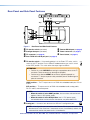
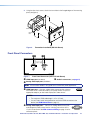
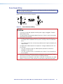
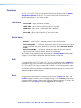
User Guide DTP Systems DTP DTP DTP DTP T T T T EU 332 EU 232 MK 332 MK 232 Two-input Universal Twisted Pair Transmitters for EU- and MK-type Junction Boxes 68-2713-01 Rev. A 09 14 Safety Instructions Safety Instructions • English WARNING: This symbol, , when used on the product, is intended to alert the user of the presence of uninsulated dangerous voltage within the product’s enclosure that may present a risk of electric shock. ATTENTION: This symbol, , when used on the product, is intended to alert the user of important operating and maintenance (servicing) instructions in the literature provided with the equipment. For information on safety guidelines, regulatory compliances, EMI/EMF compatibility, accessibility, and related topics, see the Extron Safety and Regulatory Compliance Guide, part number 68-290-01, on the Extron website, www.extron.com. Instructions de sécurité • Français AVERTISSEMENT: Ce pictogramme, , lorsqu’il est utilisé sur le produit, signale à l’utilisateur la présence à l’intérieur du boîtier du produit d’une tension électrique dangereuse susceptible de provoquer un choc électrique. ATTENTION: Ce pictogramme, , lorsqu’il est utilisé sur le produit, signale à l’utilisateur des instructions d’utilisation ou de maintenance importantes qui se trouvent dans la documentation fournie avec le matériel. Pour en savoir plus sur les règles de sécurité, la conformité à la réglementation, la compatibilité EMI/EMF, l’accessibilité, et autres sujets connexes, lisez les informations de sécurité et de conformité Extron, réf. 68-290-01, sur le site Extron, www.extron.com. Sicherheitsanweisungen • Deutsch WARNUNG: Dieses Symbol auf dem Produkt soll den Benutzer darauf aufmerksam machen, dass im Inneren des Gehäuses dieses Produktes gefährliche Spannungen herrschen, die nicht isoliert sind und die einen elektrischen Schlag verursachen können. VORSICHT: Dieses Symbol auf dem Produkt soll dem Benutzer in der im Lieferumfang enthaltenen Dokumentation besonders wichtige Hinweise zur Bedienung und Wartung (Instandhaltung) geben. Weitere Informationen über die Sicherheitsrichtlinien, Produkthandhabung, EMI/EMF-Kompatibilität, Zugänglichkeit und verwandte Themen finden Sie in den Extron-Richtlinien für Sicherheit und Handhabung (Artikelnummer 68-290-01) auf der Extron-Website, www.extron.com. Instrucciones de seguridad • Español ADVERTENCIA: Este símbolo, , cuando se utiliza en el producto, avisa al usuario de la presencia de voltaje peligroso sin aislar dentro del producto, lo que puede representar un riesgo de descarga eléctrica. ATENCIÓN: Este símbolo, , cuando se utiliza en el producto, avisa al usuario de la presencia de importantes instrucciones de uso y mantenimiento recogidas en la documentación proporcionada con el equipo. Para obtener información sobre directrices de seguridad, cumplimiento de normativas, compatibilidad electromagnética, accesibilidad y temas relacionados, consulte la Guía de cumplimiento de normativas y seguridad de Extron, referencia 68-290-01, en el sitio Web de Extron, www.extron.com. Инструкция по технике безопасности • Русский ПРЕДУПРЕЖДЕНИЕ: Данный символ, , если указан на продукте, предупреждает пользователя о наличии неизолированного опасного напряжения внутри корпуса продукта, которое может привести к поражению электрическим током. ВНИМАНИЕ: Данный символ, , если указан на продукте, предупреждает пользователя о наличии важных инструкций по эксплуатации и обслуживанию в руководстве, прилагаемом к данному оборудованию. Для получения информации о правилах техники безопасности, соблюдении нормативных требований, электромагнитной совместимости (ЭМП/ЭДС), возможности доступа и других вопросах см. руководство по безопасности и соблюдению нормативных требований Extron на сайте Extron: www.extron.com, номер по каталогу - 68-290-01. Chinese Simplified(简体中文) 警告: 产品上的这个标志意在警告用户该产品机壳内有暴露的危险 电压, 有触电危险。 注 意: 产 品 上 的 这个 标 志 意 在 提 示用 户 设 备 随 附 的 用 户 手 册 中 有 重要的操作和维护(维修)说明。 关于我们产品的安全指南、遵循的规范、EMI/EMF 的兼容性、无障碍 使用的特性等相关内容,敬请访问 Extron 网站 www.extron.com,参见 Extron 安全规范指南,产品编号 68-290-01。 Chinese Traditional( ) 警告: 若產品上使用此符號,是為了提醒使用者,產品機殼內存在著 可能會導致觸電之風險的未絕緣危險電壓。 注意 若產品上使用此符號,是為了提醒使用者。 有關安全性指導方針、法規遵守、EMI/EMF 相容性、存取範圍和相關主題的詳 細資訊,請瀏覽 Extron 網站:www.extron.com,然後參閱《Extron 安全性與 法規遵守手冊》,準則編號 68-290-01。 Japanese 警告: この記号 が製品上に表示されている場合は、筐体内に絶縁されて いない高電圧が流れ、感電の危険があることを示しています。 注意: この記号 が製品上に表示されている場合は、本機の取扱説明書 に 記載されている重要な操作と保守(整備)の指示についてユーザーの 注 意を喚起するものです。 安全上のご注意、法規厳守、EMI/EMF適合性、その他の関連項目に ついては、エクストロンのウェブサイト www.extron.com より『Extron Safety and Regulatory Compliance Guide』(P/N 68-290-01) をご覧ください。 Korean 경고: 이 기호 , 가 제품에 사용될 경우, 제품의 인클로저 내에 있는 접지되지 않은 위험한 전류로 인해 사용자가 감전될 위험이 있음을 경고합니다. 주의: 이 기호 , 가 제품에 사용될 경우, 장비와 함께 제공된 책자에 나와 있는 주요 운영 및 유지보수(정비) 지침을 경고합니다. 안전 가이드라인, 규제 준수, EMI/EMF 호환성, 접근성, 그리고 관련 항목에 대한 자세한 내용은 Extron 웹 사이트(www.extron.com)의 Extron 안전 및 규제 준수 안내서, 68-290-01 조항을 참조하십시오. FCC Class A Notice This equipment has been tested and found to comply with the limits for a Class A digital device, pursuant to part 15 of the FCC rules. The Class A limits provide reasonable protection against harmful interference when the equipment is operated in a commercial environment. This equipment generates, uses, and can radiate radio frequency energy and, if not installed and used in accordance with the instruction manual, may cause harmful interference to radio communications. Operation of this equipment in a residential area is likely to cause interference. This interference must be corrected at the expense of the user. ATTENTION: The Twisted Pair Extension technology works with shielded twisted pair (STP) cables only. To ensure FCC Class A and CE compliance, STP cables and STP Connectors are also required. For more information on safety guidelines, regulatory compliances, EMI/EMF compatibility, accessibility, and related topics, see the “Extron Safety and Regulatory Compliance Guide” on the Extron website. Copyright © 2014 Extron Electronics. All rights reserved. Trademarks All trademarks mentioned in this guide are the properties of their respective owners. The following registered trademarks®, registered service marks(SM), and trademarks(TM) are the property of RGB Systems, Inc. or Extron Electronics: Registered Trademarks (®) AVTrac, Cable Cubby, CrossPoint, eBUS, EDID Manager, EDID Minder, Flat Field, GlobalViewer, Hideaway, Inline, IP Intercom, IP Link, Key Minder, LockIt, MediaLink, PlenumVault, PoleVault, PowerCage, Pure3, Quantum, SoundField, SpeedMount, SpeedSwitch, System INTEGRATOR, TeamWork, TouchLink, V-Lock, VersaTools, VoiceLift, VN-Matrix, WallVault, WindoWall, XTP, and XTP Systems Registered Service Mark(SM) : S3 Service Support Solutions Trademarks (™) AP, AFL - Accu-RATE Frame Lock, ADSP - Advanced Digital Sync Processing, Auto-Image, CableCover, CDRS - Class D Ripple Suppression, DDSP - Digital Display Sync Processing, DMI - Dynamic Motion Interpolation, Driver Configurator, DSP Configurator, DSVP - Digital Sync Validation Processing, eLink, EQIP, FastBite, FlexOS, FOXBOX, Global Configurator, IP Intercom HelpDesk, LinkLicense, MAAP, MicroDigital, ProDSP, QS-FPC - QuickSwitch Front Panel Controller, Scope-Trigger, SIS - Simple Instruction Set, Skew-Free, SpeedNav, Triple-Action Switching, XTRA, ZipCaddy, and ZipClip Conventions Used in this Guide Notifications The following notifications are used in this guide: ATTENTION: • Risk of property damage. • Risque de dommages matériels. NOTE: A note draws attention to important information. TIP: A tip provides a suggestion to make working with the application easier. Software Commands Commands are written in the fonts shown here: ^AR Merge Scene,,Op1 scene 1,1 ^B 51 ^W^C [01] R 0004 00300 00400 00800 00600 [02] 35 [17] [03] E X! *X1&* X2)* X2$* X2@ CE} NOTE: For commands and examples of computer or device responses mentioned in this guide, the character “0” is used for the number zero and “O” is the capital letter “o.” Selectable items, such as menu names, menu options, buttons, tabs, and field names are written in the font shown here: From the File menu, select New. Click the OK button. Specifications Availability Product specifications are available on the Extron website, www.extron.com. Contents Introduction.................................................... 1 Remote Control............................................ 19 About this Guide.................................................. 1 About the Switching Transmitters........................ 1 Features.............................................................. 3 Simple Instruction Set Control........................... 19 Host-to-Switcher Communications................ 19 Switcher-Initiated Messages.......................... 19 Error responses............................................. 20 Timeout......................................................... 20 Using the Command and Response Table..... 20 Product Configuration Software......................... 26 Installing the Software.................................... 26 Starting the Program..................................... 28 Updating the Firmware.................................. 30 Installation and Operation............................ 4 Installation Overview............................................ 4 Installing the Junction Box or European Cable Channel System................................................. 6 Rear Panel and Side Panel Features.................... 7 Mounting the Switching Transmitters................... 9 Front Panel Connectors..................................... 10 Connection and Wiring Details........................... 12 HDMI Connector........................................... 12 VGA Connector Wiring.................................. 13 TP Cable Termination and Recommendations....................................... 13 IR and RS-232 Connector Wiring.................. 14 Power Supply Wiring..................................... 15 Operation.......................................................... 17 Indications..................................................... 17 Switch Modes............................................... 17 EDID.............................................................. 17 Reset............................................................. 17 Troubleshooting — If no Image Appears............ 18 DTP T EU 332, DTP T EU 232, DTP T MK 332, and DTP T MK 232 • Contents v DTP T EU 332, DTP T EU 232, DTP T MK 332, and DTP T MK 232 • Contents vi Introduction • About this Guide • About the Switching Transmitters • Features About this Guide This guide describes the following wallplate-mounted switching transmitter models: • DTP T EU 332 • DTP T EU 232 • DTP T MK 332 • DTP T MK 232 NOTE: In this guide: • The units are commonly referred to as “switchers” or as “switching transmitters.” • Unless specifically identified by the model name, the discussions in the guide apply to any model. The switchers output a signal to a compatible DTP receiver. This guide describes how to install, operate, and configure the switcher. About the Switching Transmitters The switching transmitters covered in this guide are 2-input VGA and HDMI switchers with DTP transmitter outputs (see figure 1, on the next page). The switchers are HDCP compliant, and support 1080p/60 Deep Color and 1920x1200 signals. Each switcher selects between one analog VGA and one HDMI input, including embedded audio (or DVI video with the appropriate adapter). The switcher converts the selected input, an optional analog audio input, and bidirectional RS-232 and infrared (IR) control signals to a proprietary digital signal. The switcher and a compatible DTP receiver extend the usable distance of video, audio, and control signals over a single Extron XTP DTP 24 shielded twisted pair (STP) cable (recommended) or other STP cable. The DTP T EU 332 and DTP T MK 332 are compatible with a DTP HDMI 330 Rx or DTP DVI 330 Rx receiver, with a range of up 330 feet (100 M). The DTP T EU 232 and DTP T MK 232 are compatible with a DTP HDMI 230 Rx or DTP DVI 230 Rx receiver, with a range of up 230 feet (70 M). The switchers fit into EU or MK two-gang junction boxes or European cable channel systems, depending on the transmitter model. The included external 12 VDC power supply accepts 100 to 240 VAC, 50-60 Hz. A single power supply connected to either the transmitter or the compatible receiver can power both units through the STP cable. DTP T EU 332, DTP T EU 232, DTP T MK 332, and DTP T MK 232 • Introduction 1 Display Display Extron TLP Pro 1020T 10" Tabletop TouchLink Pro Touchpanel Laptop PC DVD Display RS-232 HDMI RS-232 HDMI 1 2 4 5 7 8 0 Screen Extron DTP HDMI 230 Rx OVER DTP IR Tx Rx G Tx Rx SIG POWER 12V 0.7A MAX LINK DTP HDMI 230 Rx OUTPUTS L AUDIO R POWER 12V 0.7A MAX Receiver DTP IN IR Tx Rx G Tx Rx SIG DTP HDMI 330 Rx LINK OUTPUTS L AUDIO R Mute 9 Last More Presets Audio Control System Off Ethernet Receiver DTP IN AV Control Network Outputs CATx Cable up to 230' (70 m) 123 Presets 6 Enter December 15, 2013 - 7:58 AM Help Extron DTP HDMI 330 Rx OVER DTP RS-232 Tuner Volume Channel 3 Mute Room Control Lighting RS-232 Doc Cam VCR Tuner On Off CATx Cable up to 330' (100 m) Ethernet HDBT OUT LINK XTP IR DTP OUT Tx Rx G Tx Rx REMOTE RESET 3 5 4 7 6 INPUTS 2 SIG COM 3 Tx Rx G IN IR/SERIAL 1 2 S G 8 SIG OVER TP RS-232 DTP R 1 RELAYS 2 C 3 4 C S G DIGITAL I/O 1 2 3 LAN 1 eBUS +V +S -S G PWR OUT = 6W LAN 2 LINK XTP IR Tx Rx G Tx Rx DTP IN L 1 2 R R L L 3 4 R R L L 5 6 R HDMI IN HDMI IN CATx Cable up to 330' (100 m) POWER 12V --A MAX 1 2 SIG 3 LINK AUDIO INPUTS OVER DTP RS-232 RGB, Y, R-Y, B-Y HDMI Two Input DTP Transmitter for EU-type Junction Boxes Figure 1. 3 4 Microphones HDMI DTP OUT IR Tx Rx G Tx Rx REMOTE CONTACT 1 2 3 G TALLY 1 2 3 +V RS-232 RESET Tx Rx G Extron DTP T USW 333 Extron DTP T EU 332 R CLASS 2 WIRING 1 2 MIC/LINE 3 4 L L 1 2 R L R L 3 4 R R EXP AUDIO IN AUDIO IN DTP T EU 332 DTP T EU 332 /4 1 Audio CATx Cable up to 330' (100 m) VGA IN VGA IN 1 2 R Scaling Presentation Matrix Switcher with DTP Extension and Control Processor AUDIO IN AUDIO IN L LAN 3 +48V L Extron DTP CrossPoint 84 IPCP SA PWR HDCP HDMI VGA AUTO PWR HDCP HDMI VGA AUTO 8 4 G IR Tx Rx G Tx Rx LINK XTP 50-60 Hz Tx Rx G HDBT RS-232 1 COM 2 Tx Rx G AMP OUTPUT RS-232 DTP SIG OVER TP 4 S/PDIF OUT AUDIO OUTPUTS LINK XTP 100-240V ~ 2.0 A MAX 4 AUDIO INPUTS SIG COM 1 Tx Rx G RTS CTS IR Tx Rx G Tx Rx CONTROL 3 LINK 2 DMP EXPANSION OUTPUTS DTP CROSSPOINT 84 RS-232 1 Audio Extron Extron Extron SM 26 Surface Mount Speakers Transmitter Inputs Typical Transmitter and Receiver Application DTP T EU 332, DTP T EU 232, DTP T MK 332, and DTP T MK 232 • Introduction 2 Features Transmits HDMI or analog video, control, and analog audio up to 330 feet (100 meters) (DTP T EU 332 or DTP T MK 332) or 230 feet (70 meters) (DTP T EU 232 or DTP T MK 232) over a single STP cable — The units provides high reliability and maximum performance on an economical and easily installed cable infrastructure. Supports computer video to 1920x1200, including HDTV 1080p/60 Deep Color and 2K Accepts additional analog stereo audio signals — The DTP transmitters support a direct pass through connection for stereo analog audio signals for simultaneous transmission over the same single twisted pair cable. Analog audio is not embedded onto the digital video signal. A DTP 330 or DTP 230 receiver can output balanced and unbalanced audio, allowing streamlined integration within an AV system. The DTP output is compatible with HDBaseT-enabled devices — The DTP output can be configured to send video and embedded audio, plus bidirectional RS-232 and IR signals to HDBaseT-enabled displays. Bidirectional RS-232 and IR insertion for AV device control — Control and IR signals can be transmitted alongside the video signal over DTP connections, allowing the remote device to be controlled without the need for additional cabling. Bidirectional control insertion eliminates the need for control system wiring to remote devices. Remote powering of transmitter or receiver — For simplified installation, only one power supply is necessary to power both devices. Digital conversion of analog input signals — Analog signals are digitized, ensuring that a reliable, high quality digital video signal is sent to the output destination. EDID Minder — Automatically manages EDID communication between connected devices, ensuring that all sources power up properly and reliably output content for display. Compatible with all DTP HDMI 330 (230) and DTP DVI 330 (230) receivers, and DTP 330- (230-)enabled products — The switching transmitters can be used with the Extron IN1608, DTP CrossPoint 84, and other DTP 330- (230-)enabled products to meet application requirements. DTP T EU 332, DTP T EU 232, DTP T MK 332, and DTP T MK 232 • Introduction 3 Installation and Operation This section contains information for mounting, connecting, wiring, and operating the DTP T EU 332, DTP T MK 332, DTP T EU 232, and DTP T MK 232 . Topics in this section include: • Installation Overview • Installing the Junction Box or European Cable Channel System • Rear Panel and Side Panel Features • Mounting the Switching Transmitters • Front Panel Connectors • Connection and Wiring Details • Operation • Troubleshooting — If no Image Appears Installation Overview All models can mount into junction boxes. The DTP T EU 332 and DTP T EU 232 can mount into a European cable channel system (also known as a “trunking system”). For junction boxes, the DTP T EU 332 and DTP T EU 232 mount into European junction boxes and the DTP T MK 332 and DTP T MK 232 mount into MK junction boxes. To mount and connect the transmitters, consider the following: Ensure there is enough space between the rear panel and the back of the junction box or European cable channel system to fit connectors. The switchers require a minimum depth of 36 mm (1.4 inch). NOTE: The depth of the junction box or European cable channel system may vary. If you are using a European cable channel system with a DTP T EU 332 or DTP T EU 232, ensure the transmitter fits in the desired channel. Figure 2, on the next page, shows the dimensions of both EU transmitter models. The depth of all four transmitters is the same. If necessary, prepare the mounting surface. CAUTION: Failure to check the items listed below may result in personal injury or property damage. ATTENTION : La non-vérification des éléments listés ci-dessous peut provoquer des blessures ou dommages matériels. Ensure there are no utility cables or pipes at the intended location that might be damaged or cause injury when installing the device. Check that the installation meets the building, electrical, and safety codes. DTP T EU 332, DTP T EU 232, DTP T MK 332, and DTP T MK 232 • Installation and Operation 4 108.80 mm (4.28") Top 13.50 mm (0.53") 29.4 mm (1.16") PWR HDCP HDMI VGA AUTO VGA IN HDMI IN 80.50 mm (3.17") AUDIO IN RESET AUDIO IN HDBT CONFIG 48.8 mm (1.92") DTP DTP T EU 232 Front Figure 2. 151.50 mm (5.97") Side DTP T EU 332 and DTP T EU 232 Dimensions Choose a location that allows cable runs without interference. NOTE: Cables may need to be installed in the wall or conduits before installation. Install the junction box or European cable channel system (see Installing the Junction Box or European Cable Channel System on page 6). NOTE: Refer to the manufacturer for more junction box installation requirements. Route and connect cables to the rear panel connectors (see Rear Panel and Side Panel Features on page 7). Mount the unit into the junction box (see Mounting the Switching Transmitters on page 9). Connect inputs to the front panel connectors (see Front Panel Connectors on page 10). DTP T EU 332, DTP T EU 232, DTP T MK 332, and DTP T MK 232 • Installation and Operation 5 Installing the Junction Box or European Cable Channel System Refer to the junction box or European cable channel system manufacturer for additional installation considerations. If required to cut an opening in the mounting surface, consider the following: • For accuracy, use a template or the mounting enclosure to mark cut guidelines. • To avoid making the hole too big, cut inside the marked guidelines. CAUTION: Smooth the edges of the opening to avoid personal injury during installation and damage to the mounting device or the cables. ATTENTION : Limez les bords de l’ouverture afin d’éviter toute blessure lors de l’installation et d’endommager l’appareil de montage ou les câbles. • Secure cables with clamps or ties to provide strain relief. • Trim back and insulate shields with heat shrink. ATTENTION: • To prevent short circuits, the outer foil shield can be cut back to the point where the cable exits the cable clamp. Both braided and foil shields should be connected to an equipment ground at the other end of the cable. • Afin d’éviter les court circuits, le blindage en aluminium extérieur peut être réduit jusqu’à ce que le câble sorte de la cosse de câble. Le blindage tressé et le blindage en aluminium devraient être connectés à la masse d’un équipement à l’autre bout du câble. DTP T EU 332, DTP T EU 232, DTP T MK 332, and DTP T MK 232 • Installation and Operation 6 Rear Panel and Side Panel Features Top D EF RESET CONFIG POWER 12V 1.0 A MAX LINK Side RS-232 IR RS-232 OVER TP REMOTE OUT DTP Tx Rx G Tx Rx Tx Rx G SIG HDBT G C B A Rear Figure 3. Rear Panel and Side Panel Features A TP function switch (see below) E Remote RS-232 port (see page 8) B Configuration port (see below) F Power connector (see page 8) TP connector (see page 8) C G Reset button (see page 8) D Over TP RS-232 and IR port port (see page 8) A TP function switch — If the receiving device is in the Extron DTP series, set this switch to the DTP position. For an HDBaseT-enabled receiver type, set this switch to the HDBT position. This switch tailors the output signal as follows: HDTP DTP ATTENTION: • Position this switch BEFORE connecting the appropriate device to the TP connector. Failure to comply can damage the endpoint. • Positionnez le sélecteur AVANT de connecter l’appareil approprié au connecteur TP. Ne pas respecter cette procédure pourrait endommager le point de connexion. HDBT position — The TP output consists of HDMI with embedded audio plus RS-232 and IR. DTP position — TP output consists of HDMI with embedded audio, analog audio, RS-232 and IR, and remote power. NOTES: • When the switch is in the HDBT position, the transmitter and receiver each requires a local 12 VDC power supply. • When the switch is in the DTP position, one 12 VDC power supply, connected to either the transmitter or the receiver, can power both units. B Config port — Connect a host device to the USB mini B configuration port. CONFIG NOTE: A Configuration port connection and a Remote RS-232 port connection can both be active at the same time. If commands are sent simultaneously to both, the command that reaches the processor first is handled first. DTP T EU 332, DTP T EU 232, DTP T MK 332, and DTP T MK 232 • Installation and Operation 7 C TP connector — Plug one end of a STP cable to this RJ-45 female jack OUT on the switching transmitter. Plug the opposite end of this cable into the DTP Input RJ-45 connector on a compatible receiver (see TP Cable Termination and Recommendations on page 13 to properly wire the RJ-45 connector and for detailed NOTES). LINK SIG Signal LED indicator — Lights green when the transmitter outputs a video signal or a test pattern. Link LED indicator — Lights yellow when a device is connected and communication is established. ATTENTION: • Do not connect this connector to a computer data or telecommunications network. • Ne connectez pas ces port à des données informatiques ou à un réseau de télécommunications. D Over TP RS-232 and IR port — Plug a serial RS-232 signal, a modulated IR signal (up to 40 kHz), or both into this 3.5 mm, 5-pole direct insertion connector for bidirectional RS-232 and IR communication (see IR and RS-232 Connector Wiring on page 14 to wire the connector). RS-232 and IR data can be transmitted simultaneously. Tx Rx G Tx Rx RS-232 IR OVER TP E Remote RS-232 port — Plug a host device into the switching transmitter via the 3.5 mm, 3-pole direct insertion connector for remote control of the transmitter (see IR and RS-232 Connector Wiring on page 14 to wire the connector). • • 9600 Baud No parity • • Tx Rx G RS-232 REMOTE 8 data bits 1 stop bit F Power connector — Plug the included external 12 VDC power supply into either this 2-pole direct insertion connector (see Power Supply Wiring on page 15 to wire the connector). Or, power the receiver (see the DTP HDMI 330 User Guide or DTP HDMI 230 User Guide, available at www.extron.com) and leave the TP function switch in DTP position. POWER 12V 1.0 A MA NOTE: When the TP function switch (item A on page 7) is in the DTP position, one power supply can power both units. When the TP function switch is in the HDBT position, the transmitter and receiver each requires a local 12 VDC power supply. G Reset button — The Reset button initiates a reset of the switcher (see RESET Reset on page 17 for details). DTP T EU 332, DTP T EU 232, DTP T MK 332, and DTP T MK 232 • Installation and Operation 8 Mounting the Switching Transmitters 1. Mount the mounting plate depending on the junction box model or European cable channel system with the flanged edges pointing away from the junction box. • For EU junction boxes, use four long screws to attach the mounting plate to the junction box (see figure 4). Wall Box Mounting Plate Figure 4. • Mounting Plate Installation for the DTP T EU Units For MK junction boxes, use two long screws to attach the mounting plate to the junction box (see figure 5). Wall Box Mounting Plate Figure 5. • Mounting Plate Installation for the DTP T MK Units To install the adapter plate to a European cable channel system, refer to the manufacturer of the European cable channel system for any additional equipment or installation requirements. DTP T EU 332, DTP T EU 232, DTP T MK 332, and DTP T MK 232 • Installation and Operation 9 2. Using the four short screws, attach the transmitter to the flanged edges of the mounting plate (see figure 6). Wall Box TO A MI CP Mounting Plate R VG AU A IN VG HD HD PW DIO IN AU IN MI HD PT EU 2 23 DT IO UD IN A Figure 6. Transmitter Installation (EU Unit Shown) Front Panel Connectors AC CB PWR HDCP HDMI VGA AUTO HDMI IN AUDIO IN VGA IN AUDIO IN DTP T EU 332 Figure 7. Front Panel Connectors (DTP T EU 322 Shown) A HDMI input port (see below) B Analog video input port (see below) C Audio In connectors (see page 11) NOTE: All transmitter models in this guide have a similar front panel appearance. AHDMI input port — Connect a digital video source into the switching transmitter via this HDMI connector. It can accept HDMI, DVI (with an appropriate adapter), or dual mode DisplayPort video sources. NOTES: • The maximum HDMI cable length is 4.5 m (15 feet). • Use an Extron LockIt lacing bracket to secure the HDMI connector to the device (see HDMI Connection on page 12). B Analog video input port — Connect an analog video source (RGB and component) video source into the switching transmitter via this 15-pin HD connector. See VGA connector Wiring on page 13 to for connector pinout. DTP T EU 332, DTP T EU 232, DTP T MK 332, and DTP T MK 232 • Installation and Operation 10 C Audio In connectors — If desired, plug analog audio sources into the AUDIO IN switching transmitter via these 3.5 mm tip-ring-sleeve (TRS) jacks. NOTES: • The analog audio input on this connector is not embedded onto the digital signal and is in addition to the digital audio that may be already embedded in the HDMI inputs. • See figure 8 to identify the connector tip, ring, and sleeve when you are making connections for the switching transmitter from existing audio cables. A mono audio connector consists of the tip and sleeve. A stereo audio connector consists of the tip, ring, and sleeve. Tip (+) Ring (-) Sleeve ( ) 3.5 mm Stereo Plug Connector (balanced) Figure 8. Wiring for TRS Connector • The analog audio can be assigned to a specific input or set to be always output (see Assign analog audio SIS commands on page 22). By default, audio input is selected automatically (see Assign analog audio SIS commands on page 22 to manually select audio inputs). When the HDMI input is selected with automatic audio input selection, the transmitter prioritizes embedded digital audio. The following table shows the audio format that is sent over the DTP connection when a specific audio format is not specified. Selected Video Input HDMI Embedded Audio Present Analog Audio Present Audio Sent Over TP VGA N/A Yes Analog audio VGA N/A No No audio HDMI Yes No HDMI embedded audio HDMI Yes Yes HDMI embedded audio HDMI No Yes Analog audio HDMI No No No audio DTP T EU 332, DTP T EU 232, DTP T MK 332, and DTP T MK 232 • Installation and Operation 11 Connection and Wiring Details HDMI Connector Use the LockIt Lacing Bracket, supplied with the switcher, to securely fasten HDMI cable to device. The following instructions describe how to attach one HDMI LockIt Lacing Bracket. For more stability, attach a second HDMI LockIt Lacing Bracket to the other mounting screw. 1. Plug the HDMI cable into the panel connection (see figure 9). MI HD IN 1 4 2 3 5 Figure 9. Installing the LockIt Lacing Bracket 2. Loosen the HDMI connection mounting screw from the panel enough to allow the LockIt lacing bracket to be placed over it. The screw does not have to be removed. 3. Place the LockIt lacing bracket on the screw and against the HDMI connector, then tighten the screw to secure the bracket. ATTENTION: • Do not overtighten the HDMI connector mounting screw. The shield to which it fastens is very thin and can easily be stripped. • Ne serrez pas trop la vis de montage du connecteur HDMI. Le blindage auquel elle est attachée est très fin et peut facilement être dénudé. 4. Loosely place the included tie wrap around the HDMI connector and the LockIt lacing bracket as shown. 5. While holding the connector securely against the lacing bracket, use pliers or similar tools to tighten the tie wrap, then remove any excess length. DTP T EU 332, DTP T EU 232, DTP T MK 332, and DTP T MK 232 • Installation and Operation 12 VGA Connector Wiring The 15-pin HD (VGA) universal analog input port accepts RGB (RGBHV, RGBS, RGsB) and component video. Figure 10 shows the pinout for each format type on the connector. 5 15 1 11 Pin RGBHV RGBS Component Pin RGBHV RGBS Component 1 Red Red R-Y 9 NC NC NC 2 Green Green Y 10 Ground Ground NC 3 Blue Blue B-Y 11 NC NC NC 4, 5 NC NC NC 12 NC NC NC 6 Red return Red return R-Y return 13 H sync C sync NC 7 Green return Green return Y return 14 V sync NC NC 8 Blue return Blue return B-Y return 15 NC NC NC Figure 10. VGA Connector TP Cable Termination and Recommendations Figure 11 details the TIA/EIA T 568B wiring standard. Use this standard to terminate the DTP cable with RJ-45 connectors. Side Pins: RJ-45 Connector 12345678 Pin Insert Twisted Pair Wires TIA/EIA T 568 B Wire color 1 White-orange 2 Orange 3 White-green 4 Blue 5 White-blue 6 Green 7 White-brown 8 Brown Figure 11. TP Cable Termination NOTE: Do not use Extron UTP23SF-4 Enhanced Skew-Free AV UTP cable or STP201 cable to link the switching transmitter and receiver. The DTP T EU and DTP T MK units do not work properly with these cables. Supported cables The DTP T EU and DTP T MK units are compatible with shielded twisted pair (STP) and unshielded twisted pair (U/UTP) cable. However, Extron strongly recommends that you use STP cable to achieve best performance. ATTENTION: • To ensure FCC Class A and CE compliance, STP cables and STP connectors are required. • Afin de s’assurer de la compatibilité entre FCC Classe A et CE, les câbles STP et les connecteurs STP sont nécessaires. DTP T EU 332, DTP T EU 232, DTP T MK 332, and DTP T MK 232 • Installation and Operation 13 Cable recommendations Extron recommends using the following practices to achieve full transmission distances up to 330 feet (100 meters) (DTP T EU 332 and DTP T MK 332) or 230 feet (70 meters) (DTP T EU 232 and DTP T MK 232) and reduce transmission errors. • Use the following Extron XTP DTP 24 STP cables and DTP 24 connectors for the best performance: • XTP DTP 24/1000 Non-Plenum 1000’ (305 meters) spool 22-236-03 • XTP DTP 24P/1000 Plenum 1000’ (305 meters) spool 22-235-03 • XTP DTP 24 Plug Package of 10 101-005-02 • If not using XTP DTP 24 cable, at a minimum, Extron recommends 24 AWG, solid conductor, STP cable with a minimum bandwidth of 400 MHz. • Terminate cables with shielded connectors to the TIA/EIA-T568B standard. • Use no more than two pass-through points, which may include patch points, punch down connectors, couplers, and power injectors. If these pass-through points are required, use CAT 6 or 6a shielded couplers and punch down connectors. NOTE: When using STP cable in bundles or conduits, consider the following: • Do not exceed 40% fill capacity in conduits. • Do not comb the cable for the first 20 meters, where cables are straightened, aligned, and secured in tight bundles. • Loosely place cables and limit the use of tie wraps or hook-and-loop fasteners. • Separate twisted pair cables from AC power cables. IR and RS-232 Connector Wiring Figure 12 shows how to wire the Remote RS-232 and Over DTP RS-232 and IR connectors. IR Device Tx Rx Gnd Tx Rx G Tx Rx RS-232 IR OVER TP Tx Rx G RS-232 REMOTE Rx Tx Gnd RS-232 Device Figure 12. IR and RS-232 Connectors Wiring NOTES: • The IR Tx and Rx line pair and the RS-232 Tx and Rx line pairs must each cross once between their connectors and the source or destination. • The length and preparation of exposed wires is important (see the second and third power connector CAUTIONS on the next page for details). DTP T EU 332, DTP T EU 232, DTP T MK 332, and DTP T MK 232 • Installation and Operation 14 Power Supply Wiring NOTE: The power supply included with the switching transmitter can normally power the transmitter and the receiver. Figure 13 shows how to wire the connector. Smooth Ridges A A POWER 12V 1.0 A MAX SECTION A–A Power Supply Output Cord 3 5 Direct Insertion Connector Figure 13. Power Connector Wiring CAUTION: ATTENTION : • The wires must be kept separate while the power supply is plugged in. Remove power before wiring. • Les deux cordons d’alimentation doivent être tenus à l’écart l’un de l’autre quand l’alimentation est branchée. • The length of exposed wires is important. The ideal length is 3/16 inch (5 mm). • Any longer and the exposed wires may touch, causing a short circuit between them. • Any shorter and the wires can be easily pulled out even if tightly fastened by the captive screws. • La longueur des câbles exposés est importante. La longueur idéale est de 5 mm (3/16 inches). • S’ils sont un peu plus longs, les câbles exposés pourraient se toucher et provoquer un court circuit. • S’ils sont un peu plus courts, ils pourraient sortir, même s’ils sont attachés par les vis captives. • Do not tin the power supply leads before installing them in the connector. Tinned wires are not as secure in the connector and could be pulled out. • Ne pas étamer les conducteurs avant de les insérer dans le connecteur. Les câbles étamés ne sont pas aussi bien fixés dans le connecteur et pourraient être retirés. DTP T EU 332, DTP T EU 232, DTP T MK 332, and DTP T MK 232 • Installation and Operation 15 ATTENTION: • This product is intended to be supplied by a UL Listed power source marked “Class 2” or “LPS,” rated 12 VDC, 1.0 A minimum. Always use a power supply supplied by or specified by Extron. Use of an unauthorized power supply voids all regulatory compliance certification and may cause damage to the supply and the end product. • Ce produit est destiné à une utilisation avec une source d’alimentation listée UL avec l’appellation « Classe 2 » ou « LPS » et normée 12 Vcc, 1,0 A minimum. Utilisez toujours une source d’alimentation fournie ou recommandée par Extron. L’utilisation d’une source d’alimentation non autorisée annule toute conformité réglementaire et peut endommager la source d’alimentation ainsi que le produit final. • Unless otherwise stated, the AC/DC adapters are not suitable for use in air handling spaces or in wall cavities. • Sauf mention contraire, les adaptateurs AC/DC ne sont pas appropriés pour une utilisation dans les espaces d’aération ou dans les cavités murales. • The installation must always be in accordance with the applicable provisions of National Electrical Code ANSI/NFPA 70, article 725 and the Canadian Electrical Code part 1, section 16. The power supply shall not be permanently fixed to a building structure or similar structure. • Cette installation doit toujours être en accord avec les mesures qui s’applique au National Electrical Code ANSI/NFPA 70, article 725, et au Canadian Electrical Code, partie 1, section 16. La source d’alimentation ne devra pas être fixée de façon permanente à une structure de bâtiment ou à une structure similaire. • Power supply voltage polarity is critical. Incorrect voltage polarity can damage the power supply and the unit. The ridges on the side of the cord (see figure 13 on the previous page) identify the power cord negative lead. • La polarité de la source d’alimentation est primordiale. Une polarité incorrecte pourrait endommager la source d’alimentation et l’unité. Les stries sur le côté du cordon (voir l’illustration 13 sur la page 15) permettent de repérer le pôle négatif du cordon d’alimentation. To verify the polarity before connection, plug in the power supply with no load and check the output with a voltmeter. DTP T EU 332, DTP T EU 232, DTP T MK 332, and DTP T MK 232 • Installation and Operation 16 Operation The DTP T EU and DTP T MK units can be controlled only by SIS commands (see Simple Instruction Set Control on page 19) or the Product Configuration Software (see Product Configuration Software on page 26). This section contains basic information about operation details. Topics in this section include: Indications PWR HDCP HDMI VGA AUTO • Power LED — Lights when power is applied. • HDCP LED — Lights when the HDMI input signal is encrypted. • HDMI LED — Lights when an HDMI input signal is detected. • VGA LED — Lights when a VGA input signal is detected. • Auto LED — Lights when the device is in auto switch mode. Switch Modes The switching transmitter has three switch modes: • Manual — The input must be selected manually using an SIS command • Auto switch (VGA) — The switcher automatically selects the input with an active signal present and, if both are present, prioritizes the VGA input. This is the factory default mode. • Auto switch (HDMI) — The switcher automatically selects the input with an active signal present and, if both are present, prioritizes the HDMI input. These modes can be selected through SIS commands (see Switch mode SIS commands on page 22) or the Product Configuration Software (see the PCS Help file). EDID To manage EDID on the DTP T EU and DTP T MK units, use SIS commands (see EDID SIS commands on page 23) or the Product Configuration Software (see the PCS Help file). The DTP T EU and DTP T MK units can record and save EDID in a user memory location, select a pre-defined EDID, or use EDID from a display connected to a receiver. EDID stored in the user memory location can come from the display connected to a receiver or a custom EDID imported through the Product Software. Reset Use the recessed Reset button on the side of the transmitter (see figure 3 on page 7 and item G on page 8) to initiate a reset to the default settings. Press and hold the reset button for approximately 6 seconds. All front panel LEDs cycle. Release the button. This reset is the equivalent of issuing the Reset SIS command (EZXXX}, see page 25). DTP T EU 332, DTP T EU 232, DTP T MK 332, and DTP T MK 232 • Installation and Operation 17 Troubleshooting — If no Image Appears 1. Ensure that all devices are plugged in and powered on. The switcher is receiving power if its power LED is lit. 2. Ensure an active input is selected on the switcher or that the switcher is in auto-input switching mode. The switcher is receiving an active input if either the HDMI or VGA LED is lit. 3. Ensure that the proper signal format is supplied. 4. Check the cabling and make corrections as necessary. 5. Call the Extron S3 Sales & Technical Support Hotline if necessary. See the end of this guide for the phone number in your region of the world. DTP T EU 332, DTP T EU 232, DTP T MK 332, and DTP T MK 232 • Installation and Operation 18 Remote Control This section includes: • Simple Instruction Set Control • Product Configuration Software The DTP T EU and DTP T MK switchers can be remotely controlled via their Remote RS-232 ports and their Configuration (USB) ports. The remote host device (such as a computer or control system) sends Extron Simple Instruction Set commands. Simple Instruction Set Control The switching transmitter can be remotely controlled using SIS commands from a host device such as a computer or control system via its Configuration (USB) port (see item B on page 7) or Remote RS-232 port (see item E on page 8). The default serial port protocol of the Remote RS-232 serial port is as follows: • 9600 baud • No parity • No flow control• 1 stop bit •8-bit Host-to-Switcher Communications SIS commands consist of one or more characters per field. No special characters are required to begin or end a command character sequence. When a command is valid, the switcher executes the command and sends a response to the host device. All responses from the switcher to the host end with a carriage return and a line feed (CR/LF = ]), which signals the end of the response character string. A string is one or more characters. Switcher-Initiated Messages When a local event occurs, such as a front panel operation, loss or restoration of an input signal, or an error condition, the switcher responds by sending a message to the host. The switcher-initiated messages are listed below: © Copyright 20yy, Extron Electronics DTP T EU (MK) 332 (232), Vx.xx, 60-nnnn-nn] The switcher issues the copyright message when it first powers on. Vx.xx is the firmware version number and 60-nnnn-nn is the part number. HdbtO1*n] The switcher sends the Hdbt message whenever the side panel TP function switch is changed. n is the switch position; 0 = HDBT, 1 = DTP. DTP T EU 332, DTP T EU 232, DTP T MK 332, and DTP T MK 232 • Remote Control 19 Error responses When the switcher receives a valid SIS command, it executes the command and sends a response to the host device. If the switcher is unable to execute the command because the command is invalid or it contains invalid parameters, the switcher returns an error response to the host. The error response codes are: E01 — Invalid input channel number (out of range) E06 — Invalid channel change E10 — Invalid command E13 — Invalid parameter Timeout Pauses of 10 seconds or longer between command ASCII characters result in a timeout. The command operation is aborted with no other indication. Using the Command and Response Table The command and response table begins page 22. Symbols are used throughout the table to represent variables in the command and response fields. Command and response examples are shown throughout the table. The ASCII to HEX conversion table below is for use with the command and response table. Space ASCII to Hex Conversion Table • DTP T EU 332, DTP T EU 232, DTP T MK 332, and DTP T MK 232 • Remote Control 20 Symbol definitions ] } = Carriage return/line feed = Carriage return (no line feed) | = Pipe (can be used interchangeably with the } character) • = space E = Escape key W = Can be used interchangeably with the E character X! X@ X# X$ X% = Input number (for switching) 0 = No input 1 = HDMI input = Switch mode 0 = Manual 1 = Auto switch VGA (default) 2 = Auto switch HDMI = Input number (for audio configuration) 0 = Always output 1 = HDMI input =Status 0 = Off, disabled, not detected 1 = on, enable, or detected = Input HDCP status 0 = No source is detected 1 = Source is detected with HDCP 2 = Source detected without HDCP X^ = Output HDCP status 0 = No sink is detected 1 = Sink is detected with HDCP 2 = Sink is detected without HDCP X& = Color bit depth mode X* = EDID X( = User EDID location X1) = Raw EDID data X1! = Resolution and rate in plain text X1@ = Switch position X1# = Pixel phase X1$ = Total pixels X1% = Horizontal and vertical start X1^ = Switcher name 0 = Auto 2 = VGA input 2 = VGA input 1 = 8-bit See the table on page 23. 66 or 67 128 or 256 bytes of hexadecimal data Example: 1920x1200•@60Hz 0 = DTP 1 = HDBT 00 – 63 (32 = default) Depends on input rate 000 – 255 (128 = default) A text string of up to 24 alphanumeric characters and minus sign/hyphen (-). No blank or space characters are permitted as part of a name. The first letter must be a letter, and the last character must not be a minus sign/hyphen. X1& = Firmware version number to second decimal place (x.xx) X1* = Verbose mode 0 = clear/none 1 = verbose mode (default for RS-232 or USB) (default) 2 = tagged responses for queries 3 = verbose mode and tagged for queries DTP T EU 332, DTP T EU 232, DTP T MK 332, and DTP T MK 232 • Remote Control 21 Command and Response Table for SIS Commands Command Function SIS Command Response (Host to Unit) (Unit to Host) Additional description Select and view input NOTE: The switcher must be in manual switch mode to execute this command. If it is in either auto switch mode, it returns E06. Select an input X!! InX!•All] Select X! to transmit to the connected receiver. Example: View input selection Switch mode 1! In01•All] Select VGA input. ! X!] X! is selected. E0AUSW} E1AUSW} Ausw0] Set switch mode to normal. Set auto switch mode VGA Ausw1] Set switch mode to auto (VGA). The switcher automatically selects the VGA input if both inputs are present. Default. Set auto switch mode HDMI E2AUSW} Ausw2] Set switch mode to auto (HDMI). The switcher automatically selects the HDMI input if both inputs are present. View switch mode EAUSW} X@] Set manual switch mode Assign analog audio input to specific video input or always output audio Always output analog audio E0AFLW} Aflw0] Analog audio is output regardless of input selection (default). Assign (lock) analog audio to a specific input EX#AFLW} AflwX#] Assign analog audio to X#. View audio assignment EAFLW} X#] E0LS} SigX$HDMI•X$VGA*X$o] View the HDCP status of the HDMI input EI1HDCP} HdcpIX%] View the output HDCP status EOHDCP} HdcpOX^] Set bit depth mode to auto EV0BITD} BitdV0] Force bit depth mode to 8-bit EV1BITD} EVBITD} BitdV1] EE1HDCP} EE0HDCP} HdcpE1] EEHDCP} X$•0] Input signal status Request status of all inputs and the output X$HDMI and X$VGA are the input signal status. X$o is the output signal status. HDCP Status Output color bit depth mode Show bit depth mode Auto mode is based on sink EDID (default). X&] HDCP Authorized Device Set HDMI input to HDCP authorized Set HDMI input to HDCP not authorized View HDCP authorized status NOTE: X! = Input number X@ = Switch mode X# = Input number X$ = Status X% = Input HDCP status X^ = Output HDCP status X# = Input number X& = Color bit depth mode 0 = No input 0 = Manual 0 = Always output 0 = Not detected, authorized 0 = No source detected 0 = No sink detected 0 = Always output 0 = Auto Default. HdcpE0] 1 = HDMI input 1 = Auto switch VGA (default) 1 = HDMI input 1 = Detected, authorized 1 = Source detected with HDCP 1 = Sink detected with HDCP 1 = HDMI input 1 = 8-bit 2 = VGA input 2 = Auto switch HDMI 2 = VGA input 2 = Source detected without HDCP 2 = Sink detected without HDCP 2 = VGA input DTP T EU 332, DTP T EU 232, DTP T MK 332, and DTP T MK 232 • Remote Control 22 Command and Response Table for SIS Commands (continued) Command Function SIS Command Response (Host to Unit) (Unit to Host) Additional description EDID Minder NOTE:See the table, below, for the EDID values. EAX!*X*EDID} ESX(EDID} EdidAX!*X*] Defaults: 03 and 50. EdidSX(] Save EDID of display connected to the output to the user store slot 66 or 67. View raw EDID data EAX!EDID} ERX!EDID} X*] X1)] View EDID native resolution ENX!EDID} X1!] Assign EDID to an input Save the EDID of the connected display to a user location View the EDID assignment X* X* Value Value Read data as text from the EDID assigned and used on input X!. Read out native resolution and refresh rate from the EDID assigned to the specified input in plain text. Example: 1920x1200 @60.00Hz X* Value X* Value VGA – PC values 01 800x600 @ 60 Hz 05 1280x800 @ 60 Hz 09 1400x1050 @ 60 Hz 13 1680x1050 @ 60 Hz 02 1024x768 @ 60 Hz 06 1280x1024 @ 60 Hz 10 1440x900 @ 60 Hz 14 1920x1080 @ 60 Hz 03* 1280x720 @ 60 Hz 07 1360x768 @ 60 Hz 11 1600x900 @ 60 Hz 15 1920x1200 @ 60 Hz 04 1280x768 @ 60 Hz 08 1366x768 @ 60 Hz 12 1600x1200 @ 60 Hz 16 2048x1080 @ 60 Hz DVI – PC values 17 800x600 @ 60 Hz 21 1280x800 @ 60 Hz 25 1400x1050 @ 60 Hz 29 1680x1050 @ 60 Hz 18 1024x768 @ 60 Hz 22 1280x1024 @ 60 Hz 26 1440x900 @ 60 Hz 30 1920x1080 @ 60 Hz 19 1280x720 @ 60 Hz 23 1360x768 @ 60 Hz 27 1600x900 @ 60 Hz 31 1920x1200 @ 60 Hz 20 1280x768 @ 60 Hz 24 1366x768 @ 60 Hz 28 1600x1200 @ 60 Hz 32 2048x1080 @ 60 Hz HDMI – PC values, with 2-channel audio 33 800x600 @ 60 Hz 37 1280x1024 @ 60 Hz 41 1440x900 @ 60 Hz 45 1920x1200 @ 60 Hz 34 1024x768 @ 60 Hz 38 1360x768 @ 60 Hz 42 1600x900 @ 60 Hz 46 2048x1080 @ 60 Hz 35 1280x768 @ 60 Hz 39 1366x768 @ 60 Hz 43 1600x1200 @ 60 Hz 36 1280x800 @ 60 Hz 40 1400x1050 @ 60 Hz 44 1680x1050 @ 60 Hz 56 1080p @ 60 Hz HDMI – HDTV values, with 2-channel audio 47 480p @ 60 Hz 50✝ 720p @ 60 Hz 53 1080p @ 50/25 Hz 48 576p @ 50 Hz 51 1080i @ 50 Hz 54 1080p @ 50 Hz 49 720p @ 50 Hz 52 1080i @ 60 Hz 55 1080p @ 60/24 Hz 61 1080p @ 50/25 Hz 63 1080p @ 60/24 Hz 62 1080p @ 50 Hz 64 1080p @ 60 Hz HDMI – HDTV values, with multi-channel audio 57 720p @ 50 Hz 58 720p @ 60 Hz 59 1080i @ 50 Hz 60 1080i @ 60 Hz Output and user locations X* Source X* Source X* Source 65 Output 66 User location 1 67 User location 2 * Default for VGA input. ✝ Default for HDMI input. NOTE: X! = Input number X* = EDID X( = User EDID location X1) = Raw EDID data X1! = Resolution and rate in plain text 0 = No input 1 = HDMI input 2 = VGA input See the table above. 66 or 67 128 or 256 bytes of hexadecimal data Example: 1920x1200•@60Hz DTP T EU 332, DTP T EU 232, DTP T MK 332, and DTP T MK 232 • Remote Control 23 Command and Response Table for SIS Commands (continued) Command Function Additional description SIS Command Response (Host to Unit) (Unit to Host) Mute video 1B Vmt1] Output no video signal. Unmute video 0B Output the selected video input. Read video mute B Vmt0] X$] Mute analog audio 1Z Amt1] Output no analog audio signal. Unmute analog audio 0Z Output analog audio input. Read analog audio mute Z Amt0] X$] E1AFMT} E0AFMT} EAFMT} Afmt1] Enable HDMI audio. (Default) Afmt0] Disable HDMI audio. E2*X1#PHAS} E2+PHAS} E2–PHAS} E2PHAS} Phas2*X1#] E2*X1$TPIX} E2+TPIX} E2–TPIX} E2TPIX} Tpix2*X1$] Video mute Mute status = X$. Analog audio mute Analog audio mute status = X$. Disable (Mute) HDMI Output Embedded Audio Enable HDMI audio output Disable HDMI audio output View HDMI audio configuration X$] Pixel phase (RGB input only) Set pixel phase Increment pixel phase Decrement pixel phase View pixel phase value Phas2*X1#] Phas2*X1#] X1#] Total pixels Set total pixels value Increment total pixels Decrement total pixels View total pixels NOTE: X$ = Status X1# = Pixel phase X1$ = Total pixels 0 = Not detected, authorized 00 – 63 (32 = default) Tpix2*X1$] Tpix2*X1$] X1$] 1 = Detected, authorized Depends on input rate DTP T EU 332, DTP T EU 232, DTP T MK 332, and DTP T MK 232 • Remote Control 24 Command and Response Table for SIS Commands (continued) Command Function SIS Command Response (Host to Unit) (Unit to Host) E2*X1%HSRT} E2+HSRT} E2–HSRT} E2HSRT} Hsrt2*X1%] E2*X1%VSRT} E2+VSRT} Vsrt2*X1%] E2–VSRT} E2VSRT} Vsrt2*X1%] EO1HDBT} HdbtO1*X1@] Additional description Horizontal start Set horizontal start value Increment horizontal start Decrement horizontal start View horizontal start Hsrt2*X1%] Hsrt2*X1%] X1%] Vertical start Set vertical start value Increment vertical start Decrement vertical start View vertical start Vsrt2*X1%] X1%] TP function switch position View switch position NOTE: The “HdbtO1*“ portion of response is returned in Verbose mode 2 and 3 only. Device Name Set the unit name Set unit name to factory default View unit name EX1^CN} E•CN} ECN} Ipn•X1^] X1^] EZXXX} Zpx] I InX!•AflwX!•AuswX@•VmtX$•AmtX$] I In1•Aflw2•Ausw1•Vmt1•Amt0] Change the name to one of your choosing. Ipn•DTP-T-EU(MK)-332(232)] Reset Reset to factory setting Reset to factory defaults. Information requests Information request Example: Input 1 is selected, analog audio is assigned to input 2, the switcher is in auto-input switching (high) mode, video is muted and analog audio is unmuted. Request part number N 60-nnnn-nn] Query controller firmware version Q X1&] 1.23] Example: Q See www.extron.com, for part numbers. The factory-installed controller firmware version is 1.23 (sample value only). Verbose mode NOTE: If tagged responses are enabled (modes 2 and 3), all “view” commands return the prefix and the value, just as the “set” commands do. For example, the View front panel switch mode (EAUSW}) command returns “AuswX@]”. Set verbose mode Read verbose mode NOTE: EX1*CV} ECV} X! = Input number X@ = Switch mode X$ = Status X1@ = Switch position X1% = Horizontal and vertical start X1^ = Switcher name 0 = No input 0 = Manual 0 = Not enabled 0 = DTP 000 – 255 (128 = default) VrbX1*] X1*] 1 = HDMI input2 = VGA input 1 = Auto switch VGA (default) 1 = Enabled 1 = HDBT 2 = Auto switch HDMI A text string of up to 24 alphanumeric characters and minus sign/hyphen (-). No blank or space characters are permitted as part of a name. The first letter must be a letter, and the last character must not be a minus sign/hyphen. X1& = Firmware version number to second decimal place (x.xx) X1* = Verbose mode 0 = clear/none 2 = tagged responses for queries 1 = verbose mode (default) 3 = verbose mode and tagged for queries DTP T EU 332, DTP T EU 232, DTP T MK 332, and DTP T MK 232 • Remote Control 25 Product Configuration Software This section details the Product Configuration Software (PCS), available on the Extron website. The Windows-based PCS communicates with the switcher via the following ports: • Configuration port — A standard USB mini-B port (see item B on page 7). • Remote RS-232 port — A serial port on a 3.5 mm, 3-pole captive screw connector (see item E on page 8). • • 9600 Baud No parity • • 8 data bits 1 stop bit The program is compatible with Windows 2000, Windows XP, and later. Installing the Software The PCS, version 2.3 or newer, and Firmware Loader are available on the Extron website. Download and install both programs as follows: NOTE: Steps 1 through 6, below, are also used to download a firmware update package. 1. Visit the website www.extron.com and click the Download tab (see figure 15). 1 2 — OR — 3 2 2 Figure 15. Downloading a Software or Firmware Package (PCS Shown) 2. Click the Software, Firmware, or specific firmware package link as appropriate to the operation you are performing. DTP T EU 332, DTP T EU 232, DTP T MK 332, and DTP T MK 232 • Remote Control 26 3. Click Download for the desired software or firmware to download and (see figure 15). TIP: Jump to the nearest page of downloads by clicking the desired filtering letter. The Download Center dialog box appears (see figure 16). 1 2 Figure 16. Download Center Dialog Box 4. Enter the requested personal information (see figure 16, 1). TIP:Click Remember Me to eliminate step 4 in future downloads. 5. Click Download to copy the software or firmware to the computer (2). The download warns you about downloads and asks you to confirm it (see figure 17). 3 Figure 17. Download Warning and Confirmation NOTE: Figure 17 may appear different or may not appear at all, depending on your web browser choice and its security settings. 6. Cick Run to confirm that you want to run the installation (3). 7. For a firmware download, exit this procedure and return to Updating the Firmware on page 30. DTP T EU 332, DTP T EU 232, DTP T MK 332, and DTP T MK 232 • Remote Control 27 8. Follow the on-screen instructions. The installation creates the necessary subfolders of C:\Program Files and the necessary groups. It places the appropriate icons into the correct group folders: NOTE: C:\Program Files(x86)\ ... for 64-bit Windows OS. Product Configuration Software — • Folder — C:\Program Files\Extron\ Extron PCS • Group folder —Extron Electronics\Extron Product Configuration Software • • • • Check for Extron PCS Updates Extron PCS Help Extron Product Configuration Software Uninstall Extron Product Configuration Software Firmware Loader — • Folder — C:\Program Files\Extron\FWLoader • Group folder —Extron Electronics\Firmware Loader • • • • Check for Firmware Loader Updates Firmware Loader Help Firmware Loader Uninstall Firmware Loader Starting the Program Start the Extron Product Configuration Software as follows: 1. Click Start > Programs > Extron Electronics > Extron Product Configuration Software > Extron Product Configuration Software. The Product Configuration Software opens to the Device Discovery screen (see figure 18). 1 2 Figure 18. Device Discovery Screen 2. Select (click) your DTP T EU or DTP T MK unit (see figure 18, 1) and click Connect (2). The Product Configuration Software opens to the Input/Output Configuration page (see figure 19 on the next page). Operate the Product Configuration Software as described in the PCS Help (click Extron PCS Help). DTP T EU 332, DTP T EU 232, DTP T MK 332, and DTP T MK 232 • Remote Control > 28 Figure 19. Product Configuration Software DTP T EU 332, DTP T EU 232, DTP T MK 332, and DTP T MK 232 • Remote Control 29 Updating the Firmware The Product Configuration Software can call the Firmware Loader utility, which provides a way to replace the firmware that is coded on the control board of the switcher without taking the unit out of service. NOTE: Upgrading the firmware does not overwrite the current configuration. Update the unit firmware as follows: 1. Perform steps 1 through 6 of Installing the Software, on page 26, to download the firmware upgrade from the Extron website, www.extron.com. 2. Click Run in the File Download dialog box (see figure 20 on the next page, 1) and Security Warning dialog box (2). The PC downloads the firmware update from the Extron website and starts the Extron Installation Program to extract the firmware file. 3. Click Next (3). The program extracts the firmware files and places them in a folder identified in the InstallShield Wizard window. ATTENTION: • The extension of the firmware file must be .s19. Opening a file with an incorrect extension may cause the device to stop functioning. • L’extension du fichier firmware doit être .s19. Si un fichier est ouvert avec une mauvaise extension, l’appareil peut arrêter de fonctionner. NOTES: • Note the folder to which the firmware file is saved. When downloaded from the Extron website, the firmware is placed in a subfolder of: • 64-bit Windows OS: C:\Program Files (x86)\Extron\Firmware. • 32-bit Windows OS: C:\Program Files\Extron\Firmware. • The original factory-installed firmware is permanently available on the unit. If the attempted firmware upload fails, the unit reverts to the factory-installed firmware. 4. Click Finish to exit the program (4). DTP T EU 332, DTP T EU 232, DTP T MK 332, and DTP T MK 232 • Remote Control 30 1 2 3 Folder where firmware is saved. 4 Figure 20. Extracting Firmware Upgrade Files 5. Connect the computer to the Configuration port (see item B on page 7) or Remote RS-232 port (see item E on page 8) of the switcher. DTP T EU 332, DTP T EU 232, DTP T MK 332, and DTP T MK 232 • Remote Control 31 6. Start the Product Configuration Software and connect to the unit (see Starting the Program, steps 1, 2, 3, and 5, starting on page 28. 7. Click Tools > Update firmware. The software asks you to confirm that you want to continue the update (see figure 21). 1 2 3 4 5 Figure 21. Updating Firmware 8. Click Continue (see figure 21, 1). The Product Configuration Software disconnects itself from the unit and calls the Firmware Loader utility in the background. The Update Firmware dialog box appears. 9. Click Browse (2). The Open dialog box opens. 10. Navigate to the folder where you saved the firmware upgrade file (see figure 21, above). Select the file (3) and click Open (4). The Update Firmware dialog box returns to the top. DTP T EU 332, DTP T EU 232, DTP T MK 332, and DTP T MK 232 • Remote Control 32 11. Click Update to continue see figure 21 on the previous page, 5). The Firmware Loader utility tests the connection, installs the update, and then verifies the firmware. At the conclusion of the process, the utility reports Upload Complete. 12. Click Close. The Product Configuration Software window returns to the front. 13. Click the in the connection tab to completely disconnect the program from the unit and then reconnect the program as described in Starting the Program, beginning at step 3 on page 28. DTP T EU 332, DTP T EU 232, DTP T MK 332, and DTP T MK 232 • Remote Control 33 Extron Warranty Extron Electronics warrants this product against defects in materials and workmanship for a period of three years from the date of purchase. In the event of malfunction during the warranty period attributable directly to faulty workmanship and/or materials, Extron Electronics will, at its option, repair or replace said products or components, to whatever extent it shall deem necessary to restore said product to proper operating condition, provided that it is returned within the warranty period, with proof of purchase and description of malfunction to: USA, Canada, South America, and Central America: Extron Electronics 1230 South Lewis Street Anaheim, CA 92805 U.S.A. Japan: Extron Electronics, Japan Kyodo Building, 16 Ichibancho Chiyoda-ku, Tokyo 102-0082 Japan Europe and Africa: Extron Europe Hanzeboulevard 10 3825 PH Amersfoort The Netherlands China: Extron China 686 Ronghua Road Songjiang District Shanghai 201611 China Asia: Extron Asia Pte Ltd 135 Joo Seng Road, #04-01 PM Industrial Bldg. Singapore 368363 Singapore Middle East: Extron Middle East Dubai Airport Free Zone F12, PO Box 293666 United Arab Emirates, Dubai This Limited Warranty does not apply if the fault has been caused by misuse, improper handling care, electrical or mechanical abuse, abnormal operating conditions, or if modifications were made to the product that were not authorized by Extron. NOTE: If a product is defective, please call Extron and ask for an Application Engineer to receive an RA (Return Authorization) number. This will begin the repair process. USA: 714.491.1500 or 800.633.9876 Asia:65.6383.4400 Europe:31.33.453.4040 Japan:81.3.3511.7655 Units must be returned insured, with shipping charges prepaid. If not insured, you assume the risk of loss or damage during shipment. Returned units must include the serial number and a description of the problem, as well as the name of the person to contact in case there are any questions. Extron Electronics makes no further warranties either expressed or implied with respect to the product and its quality, performance, merchantability, or fitness for any particular use. In no event will Extron Electronics be liable for direct, indirect, or consequential damages resulting from any defect in this product even if Extron Electronics has been advised of such damage. Please note that laws vary from state to state and country to country, and that some provisions of this warranty may not apply to you. Extron Headquarters Extron Europe Extron Asia Extron Japan +1.800.633.9876 (Inside USA/Canada Only) Extron USA - West Extron USA - East +1.714.491.1500+1.919.850.1000 +1.714.491.1517 FAX +1.919.850.1001 FAX +800.3987.6673 (Inside Europe Only) +31.33.453.4040 +31.33.453.4050 FAX +65.6383.4400 +65.6383.4664 FAX +81.3.3511.7655 +81.3.3511.7656 FAX Extron China +86.21.3760.1568 +86.21.3760.1566 FAX Extron Middle East Extron Korea Extron India +971.4.299.1800 +971.4.299.1880 FAX +82.2.3444.1571 +82.2.3444.1575 FAX 1800.3070.3777 (Inside India Only) +91.80.3055.3777 +91.80.3055.3737 FAX © 2014 Extron Electronics All rights reserved. www.extron.com