1
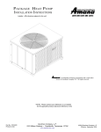
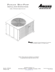
PACKAGE HEAT PUMP
INSTALLATION INSTRUCTIONS
Installer: Affix literature adjacent to the unit.
is a trademark of Maytag Corporation and is used under
license to Goodman Company, L.P. All rights reserved.
®
*NOTE: Please contact your distributor or our website
for the applicable product data book referred to in this
Part No. 10730420
Printed in USA
Goodman Company, L.P.
1810 Wilson Parkway • Fayetteville, Tennessee 37334
www.amana-hac.com
2000-2004 Goodman Company, L.P.
Effective: July 2004
SAFETY INSTRUCTIONS
RECOGNIZE SAFETY SYMBOLS, WORDS, AND LABELS
The following symbols and labels are used throughout this manual to indicate immediate or potential safety hazards. It is the owner’s and
installer’s responsibility to read and comply with all safety information and instructions accompanying these symbols. Failure to heed
safety information increases the risk of personal injury, property damage, and/or product damage.
WARNING
WARNING - Hazards or unsafe practices which COULD result in severe personal injury or death.
CAUTION
CAUTION - Hazards or unsafe practices which COULD result in minor or moderate personal injury, product damage, property damage.
WARNING
TO AVOID PROPERTY DAMAGE, PERSONAL INJURY OR DEATH, DO NOT USE THIS UNIT IF ANY PART HAS BEEN UNDER WATER. IMMEDIATELY CALL A
QUALIFIED SERVICE TECHNICIAN TO INSPECT THE FURNACE AND TO REPLACE ANY PART OF THE CONTROL SYSTEM AND ANY GAS CONTROL HAVING BEEN
UNDER WATER.
WARNING
TO PREVENT PROPERTY DAMAGE, PERSONAL INJURY OR DEATH DUE TO IMPROPER INSTALLATION, ADJUSTMENTS, ALTERATIONS, SERVICE OR MAINTENANCE,
CONSULT THIS MANUAL, THE SERVICE MANUAL, A QUALIFIED INSTALLER OR A SERVICE AGENCY.
WARNING
THIS PRODUCT CONTAINS OR PRODUCES A CHEMICAL(S) WHICH MAY CAUSE DEATH OR SERIOUS ILLNESS AND WHICH ARE KNOWN BY THE STATE OF
CALIFORNIA TO CAUSE CANCER, BIRTH DEFECTS OR OTHER REPRODUCTIVE HARM.
ATTENTION INSTALLING PERSONNEL
As a professional installer you have an obligation to know the product better than the customer. This includes all
safety precautions and related items.
Prior to actual installation, thoroughly familiarize yourself with this Instruction Manual. Pay special attention to all safety
warnings. Often during installation or repair it is possible to place yourself in a position which is more hazardous than
when the unit is in operation.
Remember, it is your responsibility to install the product safely and to know it well enough to be able to instruct a
customer in its safe use.
Safety is a matter of common sense...a matter of thinking before acting. Most dealers have a list of specific good
safety practices...follow them.
The precautions listed in this Installation Manual are intended as supplemental to existing practices. However, if there
is a direct conflict between existing practices and the content of this manual, the precautions listed here take
precedence.
2
conditioned. The loads should be calculated by an approved method
or in accordance with A.S.H.R.A.E. Guide or Manual J - Load Calculations published by the Air Conditioning Contractors of America.
Obtain from:
GENERAL INFORMATION
TO THE INSTALLER
Before installing this unit please read this manual and the Product
American National Standards Institute
Data Book applicable to your model* to familiarize yourself on the
1430 Broadway
specific items which must be adhered to such as maximum external
New York, NY 10018
static pressure to unit, air temperature rise, minimum or maximum
CFM and motor speed connections.
TRANSPORTATION DAMAGE
TO THE OWNER
All units are securely packed in shipping containers tested according to International Safe Transit Association specifications. The carton should be checked upon arrival for external damage. If damage
is found, a request for inspection by carrier agent should be made in
writing immediately.
The unit should be carefully inspected upon arrival for damage and
bolts or screws which may have loosened in transit. In the event of
damage, the consignee should:
1. Make notation on delivery receipt of any visible damage to
shipment or container.
2. Notify carrier promptly and request an inspection.
3. In case of concealed damage, carrier should be notified as
soon as possible-preferably within 5 days.
4. File the claim with the following supporting documents within
the 9 month statute of limitations.
a. Original Bill of Lading, certified copy, or indemnity bond.
b. Original paid freight bill or indemnity in lieu thereof.
c. Original invoice or certified copy thereof, showing trade and
other discounts or reductions.
d. Copy of the inspection report issued by carrier
representative at the time damage is reported to the carrier.
The carrier is responsible for making prompt inspection of
damage and for a thorough investigation of each claim.
The distributor or manufacturer will not accept claims from
dealers for transportation damage.
NOTE: When inspecting the unit for transportation damage, remove
all packaging materials. Recycle or dispose of the packaging material according to local codes.
It is important to complete the owner registration card and mail it
immediately. This will assist us in contacting you if any service or
warranty information should change in the future. When completing
the registration card, be sure to include the Model, Manufacturing
and Serial Numbers, plus the installation date.
The warranty certificate is also supplied with the unit. Read the warranty carefully and note what is covered. Keep the warranty certificate in a safe place so you can find it if necessary.
If additional operating instructions are required, call the dealer where
the purchase was made. Keep this literature in a safe place for future reference.
UNIT PLACEMENT
WARNING
TO PREVENT POSSIBLE EQUIPMENT DAMAGE, PROPERTY DAMAGE, PERSONAL
INJURY OR DEATH, THE FOLLOWING BULLET POINTS MUST BE OBSERVED
WHEN INSTALLING THE UNIT.
ALL INSTALLATIONS:
Ground Level Installations Only:
•
•
When the unit is installed on the ground adjacent to the
building, a level concrete (or equal) base is recommended.
Prepare a base the same physical size as the unit or slightly
larger and 3 inches thick.
The base should also be located where no runoff of water
from higher ground can collect in the unit.
RIGGING AND HANDLING
Rooftop Installations Only:
•
To avoid possible personal injury or property damage, the
roof must have sufficient structural strength to carry the
weight of the unit(s) and snow or water loads as required by
local codes.
• If horizontal air delivery is used, the unit may be installed
directly on wood floors or on Class A, Class B, or Class C
roof covering material.
• To avoid possible personal injury, a safe, flat surface for
service personnel must be provided.
• If vertical air discharge is used and the unit is installed on
combustible flooring or class A, B, or C roofing material,
then the Amana® brand roof curb (PRC06A1 or PRC08A1)
is required.
This unit is approved only for an outdoor installation. To assure
that your unit operates safely and efficiently, it must be installed,
operated, and maintained in accordance with these installation and
operating instructions, all local building codes and ordinances.
The heating and cooling capacities of the unit should be greater than
or equal to the design heating and cooling loads of the area to be
WARNING
TO PREVENT PROPERTY DAMAGE, THE UNIT SHOULD REMAIN IN AN UPRIGHT
POSITION DURING ALL RIGGING AND MOVING OPERATIONS. TO FACILITATE
LIFTING AND MOVING WHEN A CRANE IS USED, PLACE THE UNIT IN AN
ADEQUATE CABLE SLING.
IMPORTANT: If using bottom discharge with roof curb, ductwork
should be attached to the curb prior to installing the unit. Ductwork
dimensions are shown in Amana® brand roof curb installation instructions.
Refer to the Roof Curb Installation Instructions for proper curb installation. Curbing must be installed in compliance with the National
Roofing Contractors Association Manual.
NOTE: Lower unit carefully onto roof mounting curb. While rigging
unit, center of gravity may cause condenser end to be lower than
supply air end.
*NOTE: Please contact your distributor or our website for the applicable product data book referred to in this manual.
3
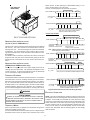
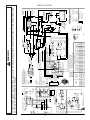
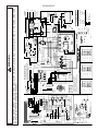
blower section, to allow splicing-in of field-installed wiring, or connect to terminal strip in unit control box.
See the unit wiring diagram for electrical connections.
Fork Lift From
Back Of Unit
ROOM THERMOSTAT
OUTDOOR UNIT
PH__C02E
C/X
G
Y
R
O
W1
W2
E
C/X
G
Y
R
O
W
W1
W2
Wiring shown is for D9945804 (THSMEC1H2BA) thermostat.
ROOM THERMOSTAT
C/X
G
Y
R
O
OUTDOOR UNIT
PH__C02E
C/X
G
Y
R
O
W2
E
W1
W2
W
Wiring shown is for 10636701(THSADC1H2BA) or
10636702 (THSMDC1H2BA) thermostat
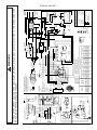
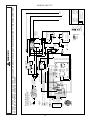
PHD60 TWO-STAGE
Rigging
Yellow No. 20 Wire in Blower Section
DUCT CONNECTIONS
ROOM THERMOSTAT
C
G
Y2
Y1
R
O
W1
W2
Y
R
O
W
W1
W3
HORIZONTAL AIRFLOW INSTALLATIONS
(24, 30, 36, 42
AND
PHB48 MODELS)
OUTDOOR UNIT C/X
G
PHD60C02E
(HEATER KIT CONTROL BOX)
Two three-inch collar connections and two square flanges are shipped
with the unit. The collar connections are located in the return air
opening of the unit. The square flanges are inside the unit blower
compartment. The square flanges can be used for either connecting 16x16 ductwork to the unit or used with a Horizontal Duct Cover
kit (CHK001A).
To install the collar connections, remove the two collars, reverse and
snap them back into place in the outlet and inlet openings. Be sure
the flanges are to the outside of the unit. Secure with screws provided.
W2
Wiring shown is for
1213412 (1F95-371) thermostat.
NOTE: If Electric Heater Kit is not installed or low voltage connection is made
in unit control box, connect as follows.
HORIZONTAL AIRFLOW INSTALLATIONS
ROOM THERMOSTAT
C
G
Y2
Y1
R
O
W1
OUTDOOR UNIT
PHD60C02E
(CONTROL BOX)
C
G
Y
Y1
R
O
W
W2
W3
Wiring shown is for 1213412 (1F95-371) thermostat.
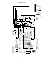
ROOM THERMOSTAT
C/X
G
Y
R
O
W1
W2
E
OUTDOOR UNIT
PH__CC2E
C/X
G
Y
R
O
W
W1
W2
(PHD48/60 and PHB60 models only)
These units are equipped with 14x14 square supply and return air
openings for horizontal air flow. The openings are flanged for ease
of duct connection. A 16x16 Horizontal Duct Cover kit (CHK001A)
can be used with the clips provided with the unit.
Wiring shown is for D9945804 (THSMEC1H2BA) thermostat.
THERMOSTAT PLACEMENT
Thermostat should be mounted 5 feet above the floor, on a vibration
free inside wall in a room or a hallway that has good air circulation.
Movement of air should not be obstructed by furniture, door, draperies, etc. The thermostat should not be mounted where it will be affected by drafts, hot or cold water pipes or air ducts in walls, radiant
heat from fireplace, lamps, the sun, television, etc. Consult the Instruction Sheet packaged with thermostat for mounting instructions.
ROOM THERMOSTAT
C/X
G
Y
R
O
OUTDOOR UNIT
PH__CC2E
C/X
G
Y
R
O
W
W2
E
W1
W2
Wiring shown is for 10636701(THSADC1H2BA) or
10636702 (THSMDC1H2BA) thermostat
Typical Thermostat and Unit 24 Volt Wiring Hoo2kup
WARNING
ELECTRICAL CONNECTIONS
SHOCK HAZARD!
DISCONNECT ALL ELECTRICAL POWER BEFORE ELECTRICALLY CONNECTING
OR SERVICING THIS UNIT. FAILURE TO DISCONNECT THE ELECTRICAL POWER
NOTE: The units are designed for operation on 60 Hz current and at
the voltages shown on the rating plate. All internal wiring in the unit is
complete. For the PHB**CC and PHD**CC units, the power supply
connection for the heater and unit will be at the circuit breaker in the
heater control box. For all others, the power supply may be brought
into the contactor (refer to unit wiring diagram supplied with unit).
Ensure 24 volt wiring is connected between the unit control panel
and the room thermostat. See the following figures for low voltage
field connection.
BEFORE WORKING ON THIS PRODUCT CAN CREATE A HAZARD LEADING TO
PERSONAL INJURY AND/OR DEATH.
THERMOSTAT WIRING
When an electric heater is installed, the thermostat wiring will be
made at the heater accessory box.
If a unit is installed without electric heaters, the low voltage wiring to
the blower section can be cut, either in the control box area or in the
4
Low Voltage
Terminal Strip
CAUTION
TO AVOID PROPERTY DAMAGE OR PERSONAL INJURY DUE TO FIRE, USE
ONLY COPPER CONDUCTORS.
C
G
Y
R
W
CAUTION
ON
W1
ON
W2 O
TO PREVENT IMPROPER AND DANGEROUS OPERATION DUE TO WIRING
ERRORS, LABEL ALL WIRES PRIOR TO DISCONNECTION WHEN SERVICING
CONTROLS.
VERIFY PROPER OPERATION AFTER SERVICING.
The best protection for the wiring is the lowest rated fuse or circuit
breaker which will supply power to the unit during normal operation
without nuisance trips. Such a device will provide maximum circuit
protection. DO NOT EXCEED THE MAXIMUM OVERCURRENT
DEVICE SIZE SHOWN ON UNIT DATA PLATE.
All line voltage connections must be made through weatherproof
fittings. All exterior power supply and ground wiring must be in approved weatherproof conduit. Low voltage wiring from the unit control panel to the thermostat requires coded cable.
Low Voltage Connection
Heater Kit Control Box
Low Voltage
Terminal Strip
FLEXIBLE WIRING SETUP
Line and low voltage wiring must enter the unit as shown.
REAR VIEW
ELECTRICAL
Low Voltage Connection
Unit Control Box
T2
RETURN
AIR
SUPPLY
AIR
T1
SIDE VIEW
SIDE VIEW
HEATER
KIT
BLOWER
TO CONTACTOR
GN
BK
ELECTRICAL
LOW
VOLTAGE
THERMOSTAT
BU
G
GY
Y
YL
R
RD
W
BR
W1
BR
RD
BK
5
3
4
1
BR
W2
L1
BK
VT
RD
RD
BK
BK
BU
O
0R
GY
L2
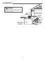
For knockout locations, see dimension drawing in the Product Data
Book applicable to your model* . Use the Single Point wiring kit to
add further flexibility to the installation wiring.
CB2
BK
BK
BU
RD
YL
1
2
3
4
5
6
7
8
9
L2
CB1
L1
SEQUENCER #1
BK
BR
COMPRESSOR
EVAP
COIL
GND-75
C
ELECT.
CONTROL
BOX
RD
VT
OL
FIELD
CONNECTION
208/240 VAC
1ø
USE COPPER
CONDUCTORS
ONLY-75°C MIN
UNIT VOLTAGE
208/230 VAC 1ø
The unit transformer is factory connected for 230V operation. If the
unit is to operate on 208V, reconnect the transformer primary lead
as shown on the unit wiring diagram.
RD
BK
BK
OL
10KW
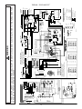
AIR CIRCULATION AND FILTERS
Field Connection
DOWNSHOT AIRFLOW CONVERSION
Refer to the unit wiring diagram (see back of manual) for electrical
connections. When installed, the unit must be electrically grounded
in accordance with local codes or in the absence of local codes, with
the National Electrical Code, ANSI/NFPA No. 70, and/or the CSA
C22.1 Electrical Code, if an external source is utilized.
Units are shipped from the factory ready for horizontal airflow. These
units can be easily converted from horizontal to downshot airflow
delivery. If conversion to vertical airflow is necessary, proceed as
follows:
Blower Rotation
WARNING
1. Cut insulation around bottom openings and remove panels
from the bottom of the unit, saving the screws holding the
panels in place.
2. From the rear of the unit, remove the four (4) screws securing
the blower assembly in place and loosen the two (2) screws
directly below the duct opening.
TO AVOID THE RISK OF ELECTRICAL SHOCK, WIRING TO THE UNIT MUST BE
POLARIZED AND GROUNDED.
*NOTE: Please contact your distributor or our website for the applicable product data book referred to in this manual.
5
require that cover clips (included with the unit) be installed to ensure a secure fit of the Horizontal Duct Covers.
24, 30, 36, 42 AND PHB48 Models:
Remove
1. Remove and set aside the four (4) supply air side screws.
2. Remove and set aside the two (2) return air side screws.
REMOVE
SCREWS
REMOVE
SCREWS
Loosen
Duct Removal
3. Remove the clamp securing the blower assembly to the
bottom of the unit. Discard clamp and screws.
SUPPLY AIR
{}
Supply Air Side Screws Removal
3. Center flange bracket and unit openings. Attach flange
brackets to the unit using the removed screws in Step 1.
Retighten screws.
4. Drill two 1/8” diameter holes on the return air side as
indicated in the figure below.
5. Secure the return air side flange bracket with the two (2)
self-tapping screws included with the unit.
Airflow
Remove
Clamp Removal
5. Rotate the blower assembly 90° clockwise, setting the blower
assembly outlet on the panel removed from bottom of the
unit.
Ensure the blower motor is oriented with the motor wires
at the bottom. This keeps condensate from puddling
inside the blower motor and causing motor failure. If
the motor is not oriented correctly, loosen the motor belly
band and rotate the motor to the correct position, then
retighten the motor belly band.
Install Screws
Removed From
Back Panel
A
lo
irf
RETURN AIR
FLANGE BRACKETS
SUPPLY AIR
Drill 2-1/8"
Dia. holes
RETURN AIR
Flange Bracket Installation
6. Align the horizontal duct covers over the flange brackets
just installed and secure with screws included in the
Horizontal Duct Cover kit.
w
Motor Leads MUST
exit at bottom
Vertical Blower Assembly
6. Secure the blower assemblyy with screws removed in step
1.
HORIZONTAL DUCT COVER INSTALLATION
The second step in the downshot airflow conversion is to install Horizontal Duct Covers. Horizontal Duct Covers are an accessory, and
Horizontal Duct Cover Alignment
can be purchased from your authorized dealer. The kit number is
CHK001A.
PHD48/60 and PHB60 Models:
PHB/PHD Models 24, 30, 36, 42, and PHB48 require that the sup1. Install cover clips (included with unit) on the inner flange
ply and return air openings be converted to square. Flanges are
sides using existing flange hole.
shipped with these units to complete this conversion.
2. With self-drilling screws provided, attach clips to the unit.
Models PHD48/60 and PHB60 supply and return air openings are
square and do not require a flange conversion. They do, however,
6
Even though a return air filter is not supplied with this unit, there
must be a means of filtering all return air.
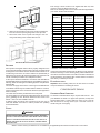
Refer to the following table or the Product Data Book applicable to
your model* for filter size information.
CLIPS
MODEL
PHB24C02*
PHB30C02*
PHB36C02*
PHB42C02*
PHB48C02*
PHB60C02*
SELF-DRILLING
SCREWS
Cover Clip Installation
3. Attach 16x16 horizontal covers using screws provided with
kit to the outer duct opening flange and cover clip holes.
4. Secure the center of the top flat cover flange to the unit
using a self-drilling screw included with the unit.
Horizontal Duct Cover Installation
DUCTWORK
Duct systems and register sizes must be properly designed for the
C.F.M. and external static pressure rating of the unit. Ductwork should
be designed in accordance with the recommended methods of Air
Conditioning Contractors of America Manual D (Residential) or
Manual Q (Commercial). All ductwork exposed to the outdoors must
include a weatherproof barrier and adequate insulation.
A duct system should be installed in accordance with Standards of
the National Board of Fire Underwriters for the Installation of Air Conditioning, Warm Air Heating and Ventilating Systems. Pamphlets No.
90A and 90B.
The warm air supply duct from the unit through a wall fabricated of
combustible material may be installed without clearance. However,
minimum clearances for the unit must be observed (see appendix in
back of manual).
The outlet duct should be provided with an access panel.
For vertical airflow, the ductwork should be attached to the roof curb
prior to installing the unit. Ductwork dimensions are shown in the
Amana ® PRC roof curb installation manual.
If desired, supply and return duct connections to the unit may be
made with flexible connections to reduce possible unit operating
sound transmission.
RATED
DISPOSABLE PERMANENT COOLING
FILTER (ft 2)2 AIRFLOW
FILTER (ft 2 )1
(CFM)
3.0
1.5
850
3.4
1.7
960
4.0
2
1170
4.5
2.3
1350
5.5
2.8
1550
6.5
3.3
1750
PHB24CC2*
PHB30CC2*
PHB36CC2*
3.0
3.4
4.0
1.5
1.7
2
850
960
1170
PHD24C02*
PHD30C02*
PHD36C02*
PHD42C02*
PHD48C02*
PHD60C02*
3.0
3.4
3.0
3.4
5.5
6.5
1.5
1.7
1.5
1.7
2.8
3.3
810
1020
1100
1200
1550
1750
PHD24CC2*
PHD30CC2*
PHD36CC2*
3.0
3.4
4.0
1.5
1.7
2
810
1020
1100
1
Based on a f ac e v eloc ity of 300 f t./min.
2
Based on a f ac e veloc ity of 600 f t./min.
If using the Over/Under Transition Kit, the filter(s) may be located in
the return air duct(s) or return air filter grille(s). Filters installed external to the unit should be sized in accordance with their manufacturer
recommendations. A throwaway filter must be sized for a maximum
face velocity of 300 feet per minute.
FILTER INSTALLATION
Important: When installing a filter, the air flow arrows on the filter
must point toward the circulating air blower.
CONDENSATE DRAIN
CONDENSATE DRAIN CONNECTION
An external condensate drain trap is required with this unit. See
your distributor for details. For proper unit operation, the trap must
be filled either before a cooling startup or during a unit “cycle-off”
after 20 minutes of running on first cycle. This drain can be extended using 3/4” PVC piping.
FILTERS
WARNING
TO AVOID PROPERTY DAMAGE, PERSONAL INJURY OR DEATH, DISCONNECT
NEVER OPERATE FURNACE
ELECTRICAL POWER BEFORE REMOVING FILTERS.
WITHOUT A FILTER INSTALLED BECAUSE DUST AND LINT WILL BUILD UP ON
INTERNAL PARTS RESULTING IN LOSS OF EFFICIENCY, EQUIPMENT DAMAGE
AND POSSIBLE FIRE.
*NOTE: Please contact your distributor or our website for the applicable product data book referred to in this manual.
7
OPERATING INSTRUCTIONS
1. Turn ON the electrical power supply to the unit.
2. Place the room thermostat selector switch in the COOL or
HEAT position (or AUTO if available, and if automatic
changeover from cooling to heating is desired).
3. Set the room thermostat to the desired temperature.
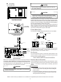
1-1/2" Minimum
drop at outlet
MAINTENANCE
90° ELL
WARNING
Condensate
Drain Trap 2-1/2" of
3/4" PVC
TO AVOID PERSONAL INJURY OR DEATH DUE TO ELECTRICAL SHOCK,
Figure 13 - Condensate Drain Connection
DISCONNECT ELECTRICAL POWER BEFORE PERFORMAING ANY
MAINTENANCE.
NORMAL SEQUENCE OF OPERATION
REPLACING OR CLEANING FILTER
NOTE: There is a fan delay on initial power to unit before the low
voltage board resets and is operational.
A return air filter is not supplied with this unit; however, there must be
a means of filtering all of the return air. The filter(s) may be located in
the return air duct(s), or return air filter grille(s). Consult with your
installing dealer for the actual location of the return air filter(s) for
your unit.
Dirty filters are the most common cause of inadequate heating or
cooling performance. Filter inspection should be made at least every two months; more often if necessary because of local conditions
and usage.
Dirty throwaway filters should be discarded and replaced with a new,
clean filter. Dirty permanent filters should be washed with water, thoroughly dried and sprayed with a filter adhesive before being reinstalled. (Filter adhesives may be found at many hardware stores.)
Permanent filters should last several years; however, should one
become torn or uncleanable, it should be replaced.
1. Thermostat calls for heating or cooling. The compressor and
outdoor fan are energized.
2. Approximately 10 seconds later, the indoor fan starts.
3. The unit will deliver heating or cooling to the conditioned
space until the thermostat is satisfied.
NOTE: PHD60 TWO-STAGE COOLING
If the room temperature is 4°F higher than thermostat
setpoint, the indoor fan will run at high speed, and the
compressor at full load. If the room temperature is within
2°F of thermostat setpoint; the indoor fan will shift to low
speed and the compressor will unload to a lower capacity.
4. The compressor and outdoor fan will be de-energized when
the thermostat opens.
5. The indoor fan continues to run for approximately 60 seconds
after the thermostat is satisfied. This allows additional cooling
from the indoor coil to be transferred to the conditioned
space. Then, the indoor fan stops.
MAINTAINING CABINET FINISH
Use a fine grade automotive wax on the cabinet finish to maintain
the finish’s original high luster. This is especially important in areas
with high ultraviolet radiation.
CLEAN OUTSIDE COIL (QUALIFIED SERVICER ONLY)
STARTUP AND ADJUSTMENT
The coil with the outside air flowing over it should be inspected annually and cleaned as frequently as necessary to keep the finned
areas free of lint, hair and debris.
WARNING
CONDENSER AND EVAPORATOR MOTORS
TO PREVENT PERSONAL INJURY OR DEATH, ALWAYS DISCONNECT THE
ELECTRICAL POWER BEFORE INSPECTING OR SERVICING THE UNIT. SINCE ALL
Bearings on the evaporator motor and the condenser motor are permanently lubricated. No additional oiling is required.
OF THE COMPRESSOR PROTECTION DEVICES RESET AUTOMATICALLY,
THE CONTACTOR AND OUTDOOR FAN MAY BE ENERGIZED WHEN RESET.
WARNING
WARNING
TO AVOID PERSONAL INJURY OR DEATH DUE TO ELECTRIC SHOCK, DO NOT
REMOVE ANY INTERNAL COMPARTMENT COVERS OR ATTEMPT ANY
THIS UNIT MUST NOT BE USED AS A "CONSTRUCTION HEATER" DURING THE
FINISHING PHASES OF CONSTRUCTION ON A NEW STRUCTURE. THIS TYPE OF
ADJUSTMENT.
USE MAY RESULT IN PREMATURE FAILURE OF THE UNIT DUE TO EXTREMELY
LOW RETURN AIR TERMPERATURES AND EXPOSURE TO CORROSIVE OR VERY
CAUTION
DIRTY ATMOSPHERES.
COMPRESSOR PROTECTION DEVICES
ALWAYS VERIFY PROPER OPERATION AFTER SERVICING.
This package heat pump unit compressor includes components which
are designed to protect the compressor against abnormal operating
conditions.
8
ACCESSORIES
Horizontal Duct Covers (CHK001A)
Single Point Power Connections (SPK**A)
Roof Curb - Heat Pump (PRC06A1)
Roof Curb - Universal (PRC08A1)
Over-Under to Side by Side (PDTROU4A)
Over-Under to Side by Side (PDTROU6A)
Additional accessories, as described above, can be purchased to fit
specific application needs. Accessories can be ordered by the part
numbers in the table and each accessory includes its own separate
instructions.
REPLACEMENT PARTS
Refer to the description in the Parts Catalog when ordering any part.
Be sure to provide the unit model, manufacturing, and serial numbers with the order.
NOTE: Details for installing and wiring electric heater kits and single
point wiring kits are contained in the installation instructions for these
accessories.
9
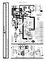
DF1
90
60
30
10
C
L1
CC
1
2
5
START
RELAY
L2
T2
XFMR C
208/230 VAC 1Ø
WARNING:DISCONNECT POWER BEFORE SERVICING.
USE COPPER CONDUCTORS ONLY
CAP
START
C
MED-LOW
MED-HIGH
PHB36C02**
LOW
COOLING
BLOWER
SPEED TAP
PHB30C02**
PHB24C02**
MODEL
NUMBER
MED
LOW
MED
LOW
MED
LOW
DOWN
BU-1
WH-7
RD-33
BR-21
RD-13
OR-49
YL-27
VT-14(COMMON)
RD-24(COOL)
RD-11
BU-23(HEAT)
LOW
LOW
LOW
HORIZ
MED
LOW
MED
LOW
MED
LOW
DOWN
LOW
LOW
LOW
HORIZ
PHCB10C1
MED
HIGH
MED
HIGH
MED
HIGH
DOWN
MED
HIGH
MED
HIGH
MED
HIGH
LOAD
BK-26
HIGH
HIGH
HIGH
DOWN
1
HIGH
HIGH
HIGH
HORIZ
PHCB20C1
BU-34
DEFROST
BOARD
VT-18
C
XFMR-C
R
G
RD-6
COOLING
SWITCH
RELAY
NO NC
COM
GY-9
VT-14
208
LINE
230
XFMR-R
BU-23
GY-9
OR-28
RD-24
HORIZ
PHCB15C1
ELECTRIC HEAT BLOWER TAP
ALTERNATE UNIT POWER REFRIGERANT
LEADS MAY BE USED WITH ELECTRIC
HEATER ACCESSORIES. SEE HEATER
ACCESSORY INSTALLATION INSTRUCTIONS.
PHCB05C1
C
T1
COMP
RD
BK
GN
BK-13
LOW
MED LOW
Y
S
R
5
BK-24
6
HI
MED HI
4
2
COMMON
3
1
R
CAP
7
VIEW A-A
8
4
5
6
9
1
2
3
A
BK-26
VT-18
YL-27
OR-49
BR-21
RD-13
BU-34
GY-70
A
BK-20
BK-19
BR
BR
AIR
CIRCULATION
BLOWER
(ACB)
W
HERM
CAP
TO
HEATER
KIT
PIN 1
PIN 2
PIN 3
PIN 4
PIN 5
PIN 6
PIN 7
PIN 8
PIN 9
REVERSING
SOLENOID
(RS)
DEFROST
THERMOSTAT
(DT)
CAPACITOR
(CAP)
O
COM
HI
MD HI
MD LO
LO
ACB
COOLING
SWITCH
RELAY
G
O
R
W
Y
C
TERMINAL BOARD
ELECTRIC
HEAT RELAY
SEQ
NO#1
230/208
ELECTRIC
HEATER
G
FAN
OD
COOLING
TAP
HEAT
TAP
Y
DF2
FAN
CAP
NO
NC
2
230/208
24V
W O
COMMON
CC
R
G
COM
5
4
RS
DT
C
R
COOLING
SWITCH
RELAY
ELECTRIC
HEAT
RELAY
DEFROST
BOARD
DF2
E
TO HEATER KIT
HEATER
KIT
W2 W1 G
TRANSFORMER
GY-55
COM
TEST
SEQ
NO#1
Y
TEST
O
90
60
30
C
DF1
RD-22
VT-7
DETAIL 1
90
60
30
O
TEST
FOR PROPER OPERATION ON 208 VOLT THE
FOLLOWING CHANGE MUST BE MADE:
MOVE RD6 WIRE FROM TRANSFORMER
230 TERMINAL TO 208 TERMINAL.
DFT
W2
R
R
W2
R
O
208 VOLT INSTALLATION
O
DFT
Y
ELECTRIC
HEAT
RELAY
C
R
2
TEST
TEST
O.D.
FAN
MOTOR
RD-31
30
60
BU
23
VT
20
VT
62
FAN
YL
12
S
R
GY GRAY
HI VOLTAGE FIELD
HI VOLTAGE
LOW VOLTAGE FIELD
LOW VOLTAGE
RD RED
GN GREEN
BK BLACK
WH WHITE
BU BLUE
VT VIOLET
BR BROWN
OR ORANGE
YL YELLOW
COLOR CODE
22303301 REV. 1
RD-27
HERM
C
COMPRESSOR
1 Ø WIRING
RD
31
USE COPPER
CONDUCTORS
ONLY75 °C MIN
L2
L1
GND
FIELDCONNECTION
208/230VAC1Ø
CAPACITOR
COM
BR-11
RD
10
BK-27
RD
31
RD-27
ELECTRIC
HEAT
RELAY
VT
16
90
1
ALTERNATE
CONFIGURATION
5
4
VT-62
3
BU-1
RD-10
L1
CONTACTOR(CC)
L2
T2
T1
VT-20
GY-8
GND
TO PREVENT PROPERTY DAMAGE, PERSONAL INJURY OR DEATH, DISCONNECT ELECTRICAL POWER TO THIS FURNACE BEFORE
SERVICING OR PERFORMING MAINTENANCE.
WARNING
PHB[24-36]C02*
XFMR R
DF1
90
60
30
11
C
L1
CC
1
2
5
START
RELAY
L2
T2
XFMR C
WARNING:DISCONNECT POWER BEFORE SERVICING.
USE COPPER CONDUCTORS ONLY
208/230 VAC 1Ø
CAP
START
C
PHB48C02**
PHB42C02**
MODEL
NUMBER
MED
LOW
COOLING
BLOWER
SPEED TAP
RD
BK
GN
BK-13
LOW
MED
YL\BK
LOW
PRESSURE
SWITCH
HI
MED
LOW
BR-21
RD-13
OR-49
WH-7
RD-33
YL-27
VT-14(COMMON)
RD-24(COOL)
RD-11
BU-23(HEAT)
MED
LOW
HORIZ
MED
LOW
DOWN
MED
LOW
HORIZ
PHCB10C1
MED
LOW
DOWN
MED
LOW
LOAD
BK-26
HIGH
MED
DOWN
1
HIGH
MED
HORIZ
PHCB20C1
BU-34
DEFROST
BOARD
VT-18
C
XFMR-C
R
G
RD-6
COOLING
SWITCH
RELAY
NO NC
COM
GY-9
VT-14
208
LINE
230
XFMR-R
BU-23
GY-9
OR-28
RD-24
HORIZ
PHCB15C1
ELECTRIC HEAT BLOWER TAP
ALTERNATE UNIT POWER REFRIGERANT
LEADS MAY BE USED WITH ELECTRIC
HEATER ACCESSORIES. SEE HEATER
ACCESSORY INSTALLATION INSTRUCTIONS.
PHCB07C1
DOWN
3
2
COMMON
C
T1
COMP
5
BK-24
6
4
1
Y
S
R
7
VIEW A-A
8
4
5
6
9
1
2
3
A
BK-26
VT-18
YL-27
OR-49
BR-21
RD-13
BU-34
GY-70
A
BK-20
BK-19
BR
BR
AIR
CIRCULATION
BLOWER
(ACB)
R
CAP
CAP
TO
HEATER
KIT
PIN 1
PIN 2
PIN 3
PIN 4
PIN 5
PIN 6
PIN 7
PIN 8
PIN 9
REVERSING
SOLENOID
(RS)
DEFROST
THERMOSTAT
(DT)
CAPACITOR
(CAP)
W
HERM
HI
MED
LO
ACB
COOLING
SWITCH
RELAY
G
O
R
W
Y
C
TERMINAL BOARD
ELECTRIC
HEAT RELAY
SEQ
NO#1
230/208
ELECTRIC
HEATER
O
FAN
OD
COOLING
TAP
HEAT
TAP
230/208
24V
COMMON
Y
G
COM
2
LPS
W O
DF2
FAN
CAP
NO
NC
CC
R
G
COM
5
4
RS
DT
C
R
COOLING
SWITCH
RELAY
ELECTRIC
HEAT
RELAY
DEFROST
BOARD
DF2
E
TO HEATER KIT
HEATER
KIT
W2 W1 G
TRANSFORMER
GY-55
COM
TEST
SEQ
NO#1
Y
TEST
O
90
60
30
C
DF1
RD-22
VT-7
DETAIL 1
90
60
30
O
TEST
FOR PROPER OPERATION ON 208 VOLT THE
FOLLOWING CHANGE MUST BE MADE:
MOVE RD6 WIRE FROM TRANSFORMER
230 TERMINAL TO 208 TERMINAL.
DFT
W2
R
R
W2
R
O
208 VOLT INSTALLATION
O
DFT
Y
ELECTRIC
HEAT
RELAY
C
R
4
2
VT
16
TEST
TEST
30
60
O.D.
FAN
MOTOR
VT
20
VT
62
FAN
YL
12
S
R
GY GRAY
HI VOLTAGE FIELD
HI VOLTAGE
LOW VOLTAGE FIELD
LOW VOLTAGE
RD RED
GN GREEN
BK BLACK
WH WHITE
BU BLUE
VT VIOLET
BR BROWN
OR ORANGE
YL YELLOW
COLOR CODE
22303901 REV. 1
RD-27
HERM
C
COMPRESSOR
1Ø WIRING
RD
31
USE COPPER
CONDUCTORS
ONLY75°C MIN
L2
L1
GND
FIELDCONNECTION
208/230VAC1Ø
CAPACITOR
COM
BR-11
RD
10
BK-27
RD
31
RD-27
ELECTRIC
HEAT
RELAY
BU
23
RD-31
90
1
ALTERNATE
CONFIGURATION
5
3
YL\BK
RD-10
L1
CONTACTOR(CC)
L2
T2
T1
VT-20
GY-8
VT-62
GND
TO PREVENT PROPERTY DAMAGE, PERSONAL INJURY OR DEATH, DISCONNECT ELECTRICAL POWER TO THIS FURNACE BEFORE
SERVICING OR PERFORMING MAINTENANCE.
WARNING
PHB[42-48]C02**
XFMR R
DF1
O
90
60
30
DEFROST
BOARD
DF2
O
Y
C
TO HEATER KIT
5
C
R2
START
RELAY
WARNING:DISCONNECT POWER BEFORE SERVICING.
USE COPPER CONDUCTORS ONLY
208/230 VAC 1 Ø
CAP
2
S
R
L2
T2
COMMON
W
Y
C
G
O
R
4
5
8
6
9
7
1
2
3
A
( )+
(-)
T EST
COOL
A
B
C
D
TEST
(-)
(+)
NORM
ADJUST
D
C
B
A
HEAT
1950
1750
1550
1350
CFM
ALTERNATE UNIT POWER REFRIGERANT
LEADS MAY BE USED WITH ELECTRIC
HEATER ACCESSORIES. SEE HEATER
ACCESSORY INSTALLATION INSTRUCTIONS.
RD
BK
GN
VIEW A-A
TO
HEATER
KIT
PIN 1
PIN 2
PIN 3
PIN 4
YL-27
OR-49
BR-21
RD-13
BU-34
GY-70
A
NORM
ADJUST
BLOWER
INTERFACE
A
B
C
D
CU T TO
EN ABLE
DE HUM ID IFY
(COOL)
DETAIL 2
D
C
B
A
GY
8
REVERSING
SOLENOID
(RS)
DEFROST
THERMOSTAT
(DT)
2000
1850
1650
BK
20
BK
13
1450
W
CC
1
FAN
OD
EM/W2
COMP
W1
230/208
24V
C1
TERMINAL BOARD
PIN 5
PIN 6
PIN 7
PIN 8
PIN 9
SEE DETAIL 2
RD
33
INDUCTOR (OPTIONAL)
RD-13
BR-21
YL-27
CFM (HEAT)
OR-49
BK
19
BK
24
GY-9
D
C
B
A
DF2
L1
T1
LPS
O
RD-31
G
HERM
CAP
COM
FAN
CC
START
RS
CAP
DT
HEATER
KIT
W2
W1
G
E
C2
W
C
R3
R
G
BLOWER
INTERFACE
Y/Y2
Y
W1
EM/W2
O
R2
R3
C1
C2
G
Y/Y2
O
W2
TEST
12
R
GY-9
VT-14
208
LINE
230
RD-6
BU-34
DEFROST
BOARD
VT-20
TEST
TEST
30
60
VT
20
VT
62
FAN
YL
12
S
R
GY GRAY
HI VOLTAGE FIELD
HI VOLTAGE
LOW VOLTAGE FIELD
LOW VOLTAGE
RD RED
GN GREEN
BK BLACK
WH WHITE
BU BLUE
VT VIOLET
BR BROWN
OR ORANGE
YL YELLOW
COLOR CODE
20424101 REV. 3
RD-27
HERM
C
COMPRESSOR
1Ø WIRING
RD
31
USE COPPER
CONDUCTORS
ONLY75 °C MIN
L2
L1
GND
FIELDCONNECTION
208/230VAC1Ø
CAPACITOR
COM
BR-11
RD
10
BK-27
VT
62
RD-27
O.D.
FAN
MOTOR
VT
16
LOWPRESSURE
SWITCH(LPS)
90
L1
CONTACTOR(CC)
L2
T2
T1
YL/BK
RD-10
GY-8
GND
ALTERNATE
CONFIGURATION
YL/BK
VT-7
DETAIL 1
1
90
60
30
HE AT
A
B
C
D
R
90
60
30
LOAD
DFT
AIR
CIRCULATION
BLOWER
RD-31
(ACB)
R
COOL
AIR
CIRCULATION
BLOWER
(ACB)
TEST
TRANSFORMER
R
COM
W2
FOR PROPER OPERATION ON 208 VOLT THE
FOLLOWING CHANGE MUST BE MADE:
MOVE RD6 WIRE FROM TRANSFORMER
230 TERMINAL TO 208 TERMINAL.
VT-14
O
208 VOLT INSTALLATION
O
A
B
C
D
TO PREVENT PROPERTY DAMAGE, PERSONAL INJURY OR DEATH, DISCONNECT ELECTRICAL POWER TO THIS FURNACE BEFORE
SERVICING OR PERFORMING MAINTENANCE.
Y
( )+
(-)
TEST
AD JUST
NOR M
DFT
DF1
TEST
C
CU T TO
EN ABLE
DE HUM ID IFY
INDUCTOR (OPTIONAL)
WARNING
PHB60 / PHD48C02**
O
R
Y
C
DF1
90
60
30
13
C
L1
CC
1
2
5
START
RELAY
L2
T2
XFMR C
WARNING:DISCONNECT POWER BEFORE SERVICING.
USE COPPER CONDUCTORS ONLY
208/230 VAC 1 Ø
CAP
START
C
PHD36C02**
PHD30C02**
PHD24C02**
MODEL
NUMBER
MED-HIGH
MED-LOW
LOW
COOLING
BLOWER
SPEED TAP
RD
BK
GN
BK-13
MED HI
3
YL\BK
LOW
PRESSURE
SWITCH
LOW
MED LOW
HI
2
COMMON
MED
LOW
MED
LOW
MED
LOW
DOWN
BR-21
RD-13
OR-49
WH-7
RD-33
YL-27
VT-14(COMMON)
RD-24(COOL)
RD-11
BU-23(HEAT)
MED
MED
LOW
HORIZ
MED
LOW
MED
LOW
MED
LOW
DOWN
MED
MED
LOW
HORIZ
PHCB10C1
MED
HIGH
MED
HIGH
MED
HIGH
DOWN
MED
HIGH
MED
HIGH
MED
HIGH
LOAD
BK-26
HIGH
HIGH
HIGH
DOWN
1
HIGH
HIGH
HIGH
HORIZ
PHCB20C1
BU-34
DEFROST
BOARD
VT-18
C
XFMR-C
R
G
RD-6
COOLING
SWITCH
RELAY
NO NC
COM
GY-9
VT-14
208
LINE
230
XFMR-R
BU-23
GY-9
OR-28
RD-24
HORIZ
PHCB15C1
ELECTRIC HEAT BLOWER TAP
ALTERNATE UNIT POWER REFRIGERANT
LEADS MAY BE USED WITH ELECTRIC
HEATER ACCESSORIES. SEE HEATER
ACCESSORY INSTALLATION INSTRUCTIONS.
PHCB05C1
C
T1
COMP
5
BK-24
6
4
1
Y
S
R
7
VIEW A-A
8
4
5
6
9
1
2
3
A
BK-26
VT-18
YL-27
OR-49
BR-21
RD-13
BU-34
GY-70
A
BK-20
BK-19
BR
BR
AIR
CIRCULATION
BLOWER
(ACB)
R
CAP
CAP
TO
HEATER
KIT
PIN 1
PIN 2
PIN 3
PIN 4
PIN 5
PIN 6
PIN 7
PIN 8
PIN 9
REVERSING
SOLENOID
(RS)
DEFROST
THERMOSTAT
(DT)
(CAP)
W
HERM
MD HI
MD LO
LO
HI
ACB
COOLING
SWITCH
RELAY
G
O
R
W
Y
C
TERMINAL BOARD
ELECTRIC
HEAT RELAY
SEQ
NO#1
230/208
ELECTRIC
HEATER
O
FAN
OD
COOLING
TAP
HEAT
TAP
230/208
24V
COMMON
Y
G
COM
2
LPS
W O
DF2
FAN
CAP
NO
NC
CC
R
G
COM
5
4
RS
DT
C
R
COOLING
SWITCH
RELAY
ELECTRIC
HEAT
RELAY
DEFROST
BOARD
DF2
E
TO HEATER KIT
HEATER
KIT
W2 W1 G
TRANSFORMER
GY-55
COM
TEST
SEQ
NO#1
Y
TEST
O
90
60
30
C
DF1
RD-22
VT-7
DETAIL 1
90
60
30
O
TEST
FOR PROPER OPERATION ON 208 VOLT THE
FOLLOWING CHANGE MUST BE MADE:
MOVE RD6 WIRE FROM TRANSFORMER
230 TERMINAL TO 208 TERMINAL.
DFT
W2
R
R
W2
R
O
208 VOLT INSTALLATION
O
DFT
Y
ELECTRIC
HEAT
RELAY
C
R
4
2
VT
16
TEST
TEST
30
60
O.D.
FAN
MOTOR
VT
20
VT
62
FAN
YL
12
S
R
GY GRAY
HI VOLTAGE FIELD
HI VOLTAGE
LOW VOLTAGE FIELD
LOW VOLTAGE
RD RED
GN GREEN
BK BLACK
WH WHITE
BU BLUE
VT VIOLET
BR BROWN
OR ORANGE
YL YELLOW
COLOR CODE
22304001 REV. 1
RD-27
HERM
C
COMPRESSOR
1Ø WIRING
RD
31
USE COPPER
CONDUCTORS
ONLY75°C MIN
L2
L1
GND
FIELDCONNECTION
208/230VAC1Ø
CAPACITOR
COM
BR-11
RD
10
BK-27
RD
31
RD-27
ELECTRIC
HEAT
RELAY
BU
23
RD-31
90
1
ALTERNATE
CONFIGURATION
5
3
YL\BK
RD-10
L1
CONTACTOR(CC)
L2
T2
T1
VT-20
GY-8
VT-62
GND
TO PREVENT PROPERTY DAMAGE, PERSONAL INJURY OR DEATH, DISCONNECT ELECTRICAL POWER TO THIS FURNACE BEFORE
SERVICING OR PERFORMING MAINTENANCE.
WARNING
PHD[24-36]C02**
XFMR R
DF1
O
90
60
30
DEFROST
BOARD
DF2
O
Y
C
TO HEATER KIT
S
2
O
5
C
R2
START
RELAY
WARNING:DISCONNECT POWER BEFORE SERVICING.
USE COPPER CONDUCTORS ONLY
208/230 VAC 1Ø
CAP
1
R
L2
T2
COMMON
G
O
R
4
5
8
6
9
7
1
2
3
A
A
B
C
D
TEST
(-)
(+)
NORM
ADJUST
D
C
B
A
HEAT
1400
1200
1000
800
CFM
ALTERNATE UNIT POWER REFRIGERANT
LEADS MAY BE USED WITH ELECTRIC
HEATER ACCESSORIES. SEE HEATER
ACCESSORY INSTALLATION INSTRUCTIONS.
RD
BK
GN
VIEW A-A
TO
HEATER
KIT
PIN 1
PIN 2
(-)
T EST
COOL
A
B
C
D
CU T TO
EN ABLE
DE HUM ID IFY
(COOL)
DETAIL 2
D
C
B
A
REVERSING
SOLENOID
(RS)
DEFROST
THERMOSTAT
(DT)
1300
1200
BK
20
BK
13
1100
900
W
CC
OD
FAN
EM/W2
COMP
W1
230/208
24V
W
Y
C
PIN 3
PIN 4
YL-27
OR-49
BR-21
RD-13
BU-34
GY-70
A
NORM
( )+
ADJUST
BLOWER
INTERFACE
GY
8
RD-13
BR-21
YL-27
CFM (HEAT)
OR-49
BK
19
BK
24
GY-9
D
C
B
A
DF2
L1
T1
LPS
C1
TERMINAL BOARD
PIN 5
PIN 6
PIN 7
PIN 8
PIN 9
SEE DETAIL 2
RD
33
RD-31
G
HERM
CAP
COM
FAN
CC
START
RS
CAP
DT
HEATER
KIT
W2
W1
G
E
R3
W
C
C2
BLOWER
INTERFACE
G
R
W2
TEST
Y/Y2
O
W1
EM/W2
O
R2
R3
C1
C2
G
Y
Y/Y2
HE AT
A
B
C
D
14
R
GY-9
VT-14
208
LINE
RD-6
BU-34
DEFROST
BOARD
L1
T2
VT-20
FAN
YL
12
S
R
TEST
TEST
RD RED
HI VOLTAGE FIELD
LOW VOLTAGE FIELD
HI VOLTAGE
LOW VOLTAGE
BK BLACK
GY GRAY
VT VIOLET
GN GREEN
WH WHITE
BU BLUE
OR ORANGE
60
30
COLOR CODE
YL YELLOW
BR BROWN
20473501 REV. 0
RD-27
HERM
C
COMPRESSOR
1Ø WIRING
RD
31
CAPACITOR
COM
BR-11
BK-27
VT
62
RD
10
VT
20
VT
62
USE COPPER
CONDUCTORS
ONLY75°C MIN
L2
L1
GND
FIELDCONNECTION
208/230VAC1Ø
90
O.D.
FAN
MOTOR
VT
16
LOWPRESSURE
SWITCH(LPS)
RD-27
L2
CONTACTOR(CC)
T1
YL/BK
RD-10
GY-8
GND
ALTERNATE
CONFIGURATION
YL/BK
VT-7
DETAIL 1
1
90
60
30
COOL
R
90
60
30
230
DFT
LOAD
R
AIR
CIRCULATION
BLOWER
(ACB)
R
A
B
C
D
AIR
CIRCULATION
BLOWER
(ACB)
TEST
TRANSFORMER
W2
COM
O
FOR PROPER OPERATION ON 208 VOLT THE
FOLLOWING CHANGE MUST BE MADE:
MOVE RD6 WIRE FROM TRANSFORMER
230 TERMINAL TO 208 TERMINAL.
VT-14
O
( )+
(-)
TEST
AD JUST
NOR M
DFT
DF1
TEST
Y
208 VOLT INSTALLATION
C
CU T TO
EN ABLE
DE HUM ID IFY
TO PREVENT PROPERTY DAMAGE, PERSONAL INJURY OR DEATH, DISCONNECT ELECTRICAL POWER TO THIS FURNACE BEFORE
SERVICING OR PERFORMING MAINTENANCE.
WARNING
PHD42C02**
O
R
Y
C
DF1
15
O
O
Y
C
208/230 VAC 1 Ø
TO HEATER KIT
START
RELAY
WARNING:DISCONNECT POWER BEFORE SERVICING.
USE COPPER CONDUCTORS ONLY
5
C
L2
T2
A
B
C
D
Y1
TEST
(-)
(+)
NORM
ADJUST
D
C
B
A
HEAT
1950
1750
1550
1350
CFM
ALTERNATE UNIT POWER REFRIGERANT
LEADS MAY BE USED WITH ELECTRIC
HEATER ACCESSORIES. SEE HEATER
ACCESSORY INSTALLATION INSTRUCTIONS.
RD
BK
GN
COOL
A
B
C
D
CU T TO
EN ABLE
DE HUM ID IFY
(COOL)
DETAIL 2
YL-37
D
C
B
A
YL
27
GY-10
REVERSING
SOLENOID
(RS)
2000
1850
1650
BK
20
RD-13
YL-29
BR-21
CFM (HEAT)
OR-49
BK
19
BK
24
DISCH
T'STAT
BK40
COMPR SOLENOID (CS)
BK
13
1450
GY-9
GY-9
D
C
B
A
BK40
BR-21
BU
VT-7
DEFR
RELAY
2ND
STAGE
LOWPRESSURE
SWITCH(LPS)
RD-6
BU-34
DEFROST
BOARD
208
LINE
230
DETAIL 1
1
TEST
TEST
30
60
90
VT
20
VT
62
FAN
YL
12
S
R
GY GRAY
HI VOLTAGE FIELD
HI VOLTAGE
LOW VOLTAGE FIELD
LOW VOLTAGE
RD RED
GN GREEN
BK BLACK
WH WHITE
BU BLUE
VT VIOLET
BR BROWN
OR ORANGE
YL YELLOW
COLOR CODE
20484301 REV. 3
RD-27
HERM
C
COMPRESSOR
1Ø WIRING
RD
31
USE COPPER
CONDUCTORS
ONLY75°C MIN
L2
L1
GND
FIELDCONNECTION
208/230VAC1Ø
CAPACITOR
COM
BR-11
RD
10
BK-27
VT
62
RD-27
O.D.
FAN
MOTOR
VT
16
BU-34
OR-49
COOL
RELAY
2ND
STAGE
VT-20
ALTERNATE
CONFIGURATION
YL-27
YL-47
YL-29
YL-10
YL-29
L1
CONTACTOR(CC)
L2
T2
T1
YL-10
RD-10
BU
YL/BK
GND
4
L1
S
2
W1
COMP
8
9
( )+
(-)
T EST
NORM
ADJUST
R
CAP
1
R
4
5
6
7
1
2
3
A
VIEW A-A
TO
HEATER
KIT
PIN 1
PIN 2
PIN 3
PIN 4
YL-29
OR-49
BR-21
RD-13
BU-34
GY-70
YL-20
BLOWER
INTERFACE
DEFROST
THERMOSTAT
(DT)
W
CC
START
FAN
OD
2ND STAGE
DEFROST RELAY
O
R
G
Y1
W
Y2
C
TERMINAL BOARD
PIN 5
PIN 6
PIN 7
PIN 8
PIN 9
A
GY
RD 8
33
INDUCTOR (OPTIONAL)
RD-31
Y1
HERM
CAP
COM
FAN
CAP
230/208
24V
R2
VT-14
G
T1
CS
CC
LPS
DT
EM/W2
LOAD
DF2
2ND
STAGE
DEFR
RELAY
2ND
STAGE
2ND STAGE
COOL RELAY
RS
DT
C1
Y1
RD-31
SEE DETAIL 2
AIR
CIRCULATION
BLOWER
(ACB)
DF1
COOL
RELAY
W2
90
60
30
DEFROST
BOARD
DF2
HEATER
KIT
W2
W1
G
E
O
W
C
R3
R
C2
BLOWER
INTERFACE
G
Y
Y/Y2
O
R
TEST
HE AT
A
B
C
D
AIR
CIRCULATION
BLOWER
(ACB)
DFT
W1
EM/W2
O
R2
R3
C1
C2
G
Y/Y2
TRANSFORMER
R
COOL
R
1
90
60
30
COM
R
VT-14
W2
FOR PROPER OPERATION ON 208 VOLT
THE FOLLOWING CHANGE MUST BE MADE:
MOVE RD6 WIRE FROM TRANSFORMER
230 TERMINAL TO 208 TERMINAL.
O
1
208 VOLT INSTALLATION
O
2
A
B
C
D
TO PREVENT PROPERTY DAMAGE, PERSONAL INJURY OR DEATH, DISCONNECT ELECTRICAL POWER TO THIS FURNACE BEFORE
SERVICING OR PERFORMING MAINTENANCE.
Y
4
( )+
(-)
TEST
AD JUST
NOR M
DFT
2
TEST
5
90
60
30
3
TEST
C
3
5
CU T TO
EN ABLE
DE HUM ID IFY
INDUCTOR (OPTIONAL)
WARNING
PHD60C02**
O
Y2
C
5
8
6
9
BK-19
A
BK-20
7
4
1
A
BK-26
VT-18
YL-27
OR-49
BR-21
RD-13
BU-34
GY-70
VIEW A-A
2
3
TO
HEATER
KIT
PIN 1
PIN 2
PIN 3
PIN 4
PIN 5
PIN 6
PIN 7
PIN 8
PIN 9
REVERSING
SOLENOID
(RS)
DEFROST
THERMOSTAT
(DT)
5
4
1
BK-13
BK-24
6
AIR
CIRCULATION
BLOWER
(ACB)
3
LOW
MED LOW
HI
MED HI
2
BU-1
WH-7
RD-33
BR-21
RD-13
OR-49
YL-27
VT-14(COMMON)
RD-24(COOL)
RD-11
BU-23(HEAT)
BK-26
OR-28
RD-24
BU-34
DEFROST
BOARD
VT-18
C
XFMR-C
R
XFMR-R
BU-23
GY-9
1
G
RD-6
COOLING
SWITCH
RELAY
NO NC
COM
GY-9
VT-14
208
LINE
230
90
60
30
BR
DFT
BR
R
COMMON
W2
CAPACITOR
(CAP)
TRANSFORMER
GY-55
COM
TEST
LOAD
O
FOR PROPER OPERATION ON 208 VOLT THE
FOLLOWING CHANGE MUST BE MADE:
MOVE RD6 WIRE FROM TRANSFORMER
230 TERMINAL TO 208 TERMINAL.
O
208 VOLT INSTALLATION
RD-22
VT-7
5
3
4
BU-1
1
VT
16
L1
O.D.
FAN
MOTOR
VT
20
VT
62
FAN
YL
12
S
R
RD-27
HERM
C
COMPRESSOR
1 Ø WIRING
RD
31
DF2
G
O
W
R
Y
C
DETAIL 1
90
TEST
TEST
30
60
ALTERNATE
CONFIGURATION
USE COPPER
CONDUCTORS
ONLY75 °C MIN
CAPACITOR
COM
BR-11
RD
10
BK-27
RD
31
RD-27
ELECTRIC
HEAT
RELAY
BU
23
RD-31
RD-10
2
T1
CONTACTOR(CC)
T2
L2
VT-20
GY-8
VT-62
GND
90
60
30
Y
16
DF1
TEST
C
R
T1
GY GRAY
GN GREEN
HI VOLTAGE FIELD
HI VOLTAGE
LOW VOLTAGE FIELD
LOW VOLTAGE
RD RED
VT VIOLET
BK BLACK
WH WHITE
BU BLUE
OR ORANGE
BR BROWN
GND
YL YELLOW
COLOR CODE
22304101 REV. 0
T2
TO PREVENT PROPERTY DAMAGE, PERSONAL INJURY OR DEATH, DISCONNECT ELECTRICAL POWER TO THIS FURNACE BEFORE
SERVICING OR PERFORMING MAINTENANCE.
WARNING
PHB[24-36]CC2**
5
8
6
9
BK-19
A
BK-20
7
4
1
A
BK-26
VT-18
YL-27
OR-49
BR-21
RD-13
BU-34
GY-70
VIEW A-A
2
3
TO
HEATER
KIT
PIN 1
PIN 2
PIN 3
PIN 4
PIN 5
PIN 6
PIN 7
PIN 8
PIN 9
REVERSING
SOLENOID
(RS)
DEFROST
THERMOSTAT
(DT)
BR
5
BK-24
RD
BK
GN
BK-13
YL\BK
LOW
PRESSURE
SWITCH
6
LOW
MED LOW
HI
MED HI
2
3
4
1
WH-7
RD-33
BR-21
RD-13
OR-49
YL-27
VT-14(COMMON)
RD-24(COOL)
RD-11
BU-23(HEAT)
DF2
G
O
W
R
Y
C
ALTERNATE UNIT POWER REFRIGERANT
LEADS MAY BE USED WITH ELECTRIC
HEATER ACCESSORIES. SEE HEATER
ACCESSORY INSTALLATION INSTRUCTIONS.
DFT
AIR
CIRCULATION
BLOWER
(ACB)
R
BR
BK-26
BU-34
DEFROST
BOARD
VT-18
C
XFMR-C
R
XFMR-R
BU-23
GY-9
OR-28
RD-24
R
COMMON
W2
CAPACITOR
(CAP)
1
90
60
30
G
RD-6
COOLING
SWITCH
RELAY
NO NC
COM
GY-9
VT-14
208
LINE
COM
230
TEST
LOAD
GY-55
TRANSFORMER
RD-22
VT-7
5
3
4
YL\BK
2
1
VT
16
O.D.
FAN
MOTOR
VT
20
VT
62
FAN
YL
12
S
R
RD-27
HERM
C
COMPRESSOR
1 Ø WIRING
RD
31
DETAIL 1
TEST
TEST
30
60
90
ALTERNATE
CONFIGURATION
USE COPPER
CONDUCTORS
ONLY75°C MIN
CAPACITOR
COM
BR-11
RD
10
BK-27
RD
31
RD-27
ELECTRIC
HEAT
RELAY
BU
23
RD-31
RD-10
L1
CONTACTOR(CC)
L2
T2
T1
VT-20
GY-8
VT-62
GND
TEST
O
DF1
90
60
30
O
17
Y
FOR PROPER OPERATION ON 208 VOLT THE
FOLLOWING CHANGE MUST BE MADE:
MOVE RD6 WIRE FROM TRANSFORMER
230 TERMINAL TO 208 TERMINAL.
C
208 VOLT INSTALLATION
T1
GY GRAY
GN GREEN
HI VOLTAGE FIELD
HI VOLTAGE
LOW VOLTAGE FIELD
LOW VOLTAGE
RD RED
VT VIOLET
BK BLACK
WH WHITE
BU BLUE
OR ORANGE
BR BROWN
GND
YL YELLOW
COLOR CODE
22304201 REV. 0
T2
PHD[24-36]CC2**
CLEARANCES
WARNING
TO AVOID
PROPERTY DAMAGE , PERSONAL INJURY OR DEATH
DUE TO FIRE, CLEARANCES TO COMBUSTIBLE SURFACES LISTED
AS SHOWN MUST BE OBSERVED.
36" Side
Clearance
for Servicing
Recommended
24" Clearance
(Condenser End)
36"
Maximum
Overhang
48" Minimum
Overhang
Vinyl Coated
Canvas
Connections
Insulate
Return
Duct
Minimum 9" Clearance
to Combustibles
36" Clearance for
Service Required
18
0" Minimum
Clearance to
Combustibles
Insulated
Supply
Duct
19
20
2000-2004 Goodman Company, L.P.
Effective: July 2004