1
Order Parts Here:
www.ivie-ent.com/parts
Ph:(918)254-5161
BEXT®-100, 100H,
150H, 300HV
120V
Extractor's
Operator's Manual
Manual del Operador
Manuel de l'operateur
READ THIS BOOK
This book has important information for the use and safe operation of this machine. Failure to read this
book prior to operating or attempting any service or maintenance procedure to your Clarke machine
could result in injury to you or to other personnel; damage to the machine or to other property could occur
as well. You must have training in the operation of this machine before using it. If your operator(s) cannot
read English, have this manual explained fully before attempting to operate this machine.
Si Ud. o sus operadores no pueden leer el Inglés, se hagan explicar este manual completamente antes
de tratar el manejo o servicio de esta máquina.
All directions given in this book are as seen from the operator’s position at the rear of the machine.
For new books write to: Clarke® , 2100 Highway 265, Springdale, Arkansas 72764.
Form No. 70416A
7/06
Clarke®
Printed in the U.S.A.
CONTENTS OF THIS BOOK
Operator Safety Instructions .................................................................................. 5
Introduction and Machine Specifications .................................................................. 6
Controls and Machine Features ............................................................................... 12
How to Prepare the Machine for Operation .............................................................. 14
Set-Up ........................................................................................................ 14
BEXT®-100 Control Panel ............................................................................. 16
BEXT®-100H Control Panel ........................................................................... 16
BEXT®-150H Control Panel ........................................................................... 18
BEXT®-300HV Control Panel ........................................................................ 18
Instructions for Connection to the Power Supply - 120V
Extension Cords - 120V ............................................................................. 20
Machine Operating Instructions ............................................................................... 22
How to Clean an Area of Carpet .................................................................. 22
How To clean a Larger Area of Carpet ......................................................... 22
Maintenance ........................................................................................................... 24
After Each Use of the Machine ................................................................... 24
How to Prevent Damage from Freezing Temperatures ................................. 26
The Pump and Vacuum Motor ................................................................... 26
How To Check The Commutator and The Carbon Brushes .......................... 28
How to Correct Problems in the Machine ................................................................. 30
BEXT®-100 Assembly Drawing ................................................................................. 34
Parts List ................................................................................................ 35
BEXT®-100H Assembly Drawing ............................................................................... 36
Parts List ................................................................................................ 37
BEXT®-150H Assembly Drawing ............................................................................... 38
Parts List ................................................................................................ 39
BEXT®-300HV Assembly Drawing ............................................................................ 40
Parts List ................................................................................................ 41
BEXT®-100 Accessories ............................................................................................ 42
BEXT®-100H Accessories ......................................................................................... 43
BEXT®-150H Accessories ......................................................................................... 44
BEXT®-300HV Accessories ....................................................................................... 45
Control Panel Wiring Diagram ................................................................................. 46
Electrical Schematic 120V ...................................................................................... 47
Page
2
Clarke® BEXT®
-100, 100H 150H, 300HV Operator's Manual
OPERATOR SAFETY INSTRUCTIONS
WARNING
AVERTISSEMENT
ADVERTENCIA
For the safe operation of this machine, read and understand all warnings and cautions.
DANGER means:
Severe bodily injury or death can occur to you or other personnel if
the DANGER statements found on your machine or in your Owner's
Manual are ignored or are not adhered to. Read and observe all
DANGER statements found in your Owner's Manual and on your
machine.
WARNING means :
Injury can occur to you or to other personnel if the WARNING
statements found on your machine or in your Owner's Manual are
ignored or are not adhered to. Read and observe all WARNING
statements found in your Owner's Manual and on your machine.
CAUTION means:
Damage can occur to the machine or to other property if the
CAUTION statements found on your machine or in your Owner's
Manual are ignored or not adhered to. Read and observe all
CAUTION statements found in your Owner's Manual and on
your machine.
DANGER:
Machines can cause an explosion when operated near flammable materials and vapors. Do not
use this machine with or near fuels, grain dust, solvents, thinners, or other flammable materials.
DANGER:
Do not immerse. To reduce the risk of an electric shock, use only on a carpet that has been
moistened by a cleaning process. Protect the machine from rain. Keep the machine in a dry
building. Always clean the machine with a clean dry cloth.
WARNING:
You must have training in the operation of this machine before using it. READ THE
INSTRUCTION BOOK FIRST.
WARNING:
Always use a three-wire electrical system connected to the electrical ground. For maximum
protection against electric shock, use a circuit that is protected by a ground fault circuit
interrupter. Consult your electrical contractor.
WARNING:
To prevent electric shock, always remove the electrical plug from the electrical outlet before
doing any repairs or maintenance to this machine.
WARNING:
Do not use this machine as a step or furniture. Injury could occur to the operator.
WARNING:
To avoid serious injury, use proper lifting procedures when lifting the machine.
WARNING:
Maintenance and repairs must be done by authorized personnel only.
WARNING:
Keep all fasteners tight. Keep the adjustments according to specifications.
WARNING:
Make sure that all the labels, decals, warnings, cautions and instructions are fastened to the
machine. Replace them when necessary by ordering them from Clarke.
WARNING:
Do not use water that is hotter than 120°F (40°C).
WARNING:
If foam/liquid comes out, stop extracting immediately. Allow vacuum('s) to run until exhaust
air is dry.
Clarke® BEXT®-100,
100H 150H, 300HV Operator's Manual
Page 5
OPERATOR SAFETY INSTRUCTIONS (CONT.)
WARNING: Improper discharge of waste water may damage the environment and be illegal. The United
States Environmental Protection Agency has established certain regulations regarding discharge of waste water. Also, city and state regulation regarding this discharge may be in effect
in your area. Understand and follow the regulations in your area. Be aware of the environmental
hazards of chemicals that you dispose.
CAUTION:
To prevent damage to the power cord, do not move this machine over the power cord, instead,
lift the power cord over the machine. If the cord supplied is damaged, it must be replaced by
the manufacturer, its service agent or a similarly qualifed person in order to avoid the hazard.
CAUTION:
To prevent damage to the power cord and hoses, do not use the power cord or hoses to pull
the machine.
CAUTION:
To prevent damage to the machine avoid extreme temperatures.
CAUTION:
To prevent damage to the machine do not let pump run dry.
INSPECTION: Carfefully unpack and inspect your new Extractor for shipping damage. Each unit is tested and inspected
before shipment. Any damage incurred is the responsibility of the carrier, who should be notified immediately.
CLEANING SOLUTIONS: We recommend liquid cleaning chemicals. A pH of 7-9 is strongly recommended to avoid
premature pump wear, which would voide the warranty.
INTRODUCTION and MACHINE SPECIFICATIONS
• The Model BEXT®-100, 100H, 150H or 300HV is an extractor for cleaning carpet. When used with a floor tool, the
machine applies cleaning solution to the carpet and removes the dirty solution and soil from the carpet.
• The extractor has controls to start the pump for the solution and the motor for the vacuum. The floor tools have controls
to release the solution.
• The extractor has a bypass pump. The pump runs when switched on, bypassing solution internally to keep pressure
even.The extractor starts when the solution lever on the floor tool is activated.
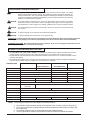
SPECIFICATIONS
Part Number
Bext 100
04156A
Bext 100H
Bext 150H
Bext 100H Detailer
Bext 150H Detailer
04157A / 04158A
04147A / 04152A
Solution Tank
Solutin Pump
9 gallon rotationally molded
100 psi demand pump
Vacuum Motor
Waterlift
5.7", 3 stage
140"
Easy Circuit Locator
On-board Heater
Wand
Power Cable
N/A
N/A
(2) - 5.7" 2-stage
150"
7.2" 3-stage
140"
Standard
Standard
Standard
Standard
Double bend twin nozzle polished stainless steel
(2) 25 ft. 12-3 hosp. grade plug
grade plug
(2) 8" non-marking & (2) 3" casters
Wheels
Hose
Low Moisture System
Float Shut-Off
Weight
Warranty
04148A
13 gallon rotationally molded
150 psi demand pump
300 psi demand pump
Standard
Standard
25 ft. 12-3 hosp.
Bext 300H
(2) 10" non-marking & (2) 2" casters
15 ft. crushproof vacuum and high pressure solution line
Standard
Standard
69 lbs.
75 lbs.
90 lbs.
119 lbs.
Product Lifetime (10 years) on tank and mainframe; 1 year Parts and labor
NOTE: When using the extractor to clean carpets, follow this procedure:
1. Do not walk on freshly cleaned carpets for at least four hours or until the carpet is dry to touch.
2. Do not remove aluminum or plastic pieces that have been placed under the legs of furniture until
the carpet is dry.
3. Do not allow children or pets to crawl or walk around on the damp carpet.
4. Vacuum right after the carpet is dry and then vacuum the carpet once a week as needed.
Page
6
Clarke® BEXT®
-100, 100H 150H, 300HV Operator's Manual
1B 1A
1H
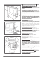
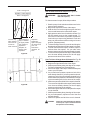
CONTROLS and MACHINE FEATURES
1C
1D
The Vacuum Motor Switches See Figure 1-A
The vacuum motor switches are located on the top of the
machine.
1G
1F
The Switch To Activate The Pump See Figure 1-B
The switch to start/stop the pump motor is on the top of the
machine. Press the lever on the floor tool to start the
solution flow. Release the lever on the floor tool to stop the
solution flow.
1E
NOTE: While the BEXT-150 machine is in operation,
the pump will shut-off automatically when it reaches
full pressure. The pump will automatically turn on
when the pressure decreases.
The Float Shut-Off -See Figure 1C
The float shut-off is in the recovery tank. When the liquid
raises the float, the air stops moving through the machine.
Figure 1
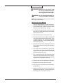
NOTE: To avoid vacuum motor damage, always
inspect the float filter and ball. Verify ball travels
easily prior to use of unit. See Figure 2
1I
The Vacuum Hose Connector See figure 1D
The vacuum hose connector is on the front of the unit.
The Solution Hose Connector See Figure 1E
The solution hose connector is on the lower part of the
extractor, below the vacuum hose connector.
1J
Figure 1
The Recovery Tank See Figure 1F
The recovery tank is in the top of the machine.
The Solution Tank See Figure 1G
The solution tank is in the top of the machine next to the
recovery tank.
Electric Circuit Locator See Figure 1H
This unique, patented "smart system", operated by a solid
state circuit, will inform the operator when the two cords
are plugged into separate circuits by illuminating the
"Locator" indicator light. This helps prevent tripping circuit
breakers.
NOTE: Ground plug on the cord is required to allow
circuit locator to operate correctly. The system will
not function without proper ground.
The Machine Power Cord (Red "H") See Figure 1I
This cord powers all machine functions except the heater.
Figure 2
Page
12
The Heater Power Cord See Figure 1J
This cord powers heater only.
Clarke® BEXT®
-100, 100H 150H, 300HV Operator's Manual
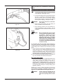
HOW TO PREPARE THE MACHINE FOR OPERATION
To prepare the machine for operation, follow this procedure:
1. Connect the vacuum hose to the hose connector
on the extractor and to the end of the vacuum tube
on the floor tool. See Figure 1 D, E
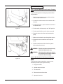
2. Connect the solution hose to the extractor and the
floor tool. To fasten the quick disconnect fitting,
slide the knurled collar on the female coupling
away from the opening. Push the male coupling
into the female coupling. See figure 3 A & B
WARNING:
Figure 3A
Do not use water that is hotter than
120°F (48°C).
3. Before moving the extractor onto the carpet, put
clean hot water into the solution tank.
4. Add a cleaning chemical, such as Clarkare® Extractor Concentrate, to the hot water. For the
correct amount, follow the directions shown on the
container.
Set-Up
WARNING:
Figure 3B
We recommend that you use liquid
cleaning chemicals. Powder can damage machine. Powders can cause
build-up in the lines, heater, pump,
quick disconnects, etc., all of which
would void the warranty on those
items. A pH of 7-9 is strongly recommended to avoid damage and premature wear to the pump, which would
void the warranty.
Fill the holding tank with clear water and the detergent of
your choice. Mix well. Although this machine is designed
to supply instant hot water, the addition of warm or hot water
to the holding tank is beneficial and will reduce pre-heat
times.
A. Plug in cord #1 (vac and pump), identified by the red "H"
on the end of the cord. Attach the priming hose to the
machine (on 300 HV only). Turn the pump on and set the
switch to the upholstery setting. Run until the pump is
fully primed, then turn off the pump. Remove the priming
hose and attach the cleaning hoses and tool.
B. Turn on the pump and spray through the cleaning tool
for a few seconds to fill the lines with solution.
BEXT® 100H, 150H & 300HV
C. Plug in cord #2. The "Locator" light will illuminate when
the cords are plugged into separate circuits. Turn the
"Heat" switch on; wait two minutes for the heat exchanger to reach operating temperature. You may now
begin cleaning. It will take about 10 seconds for the
initial heat to reach the wand. The "Mode" light will turn
on when the heat exchanger is actively heating. (See
Figures 5, 6 and 7)
NOTE: If the "Locator" indicator light does not illuminate
when cord #2 is plugged in, then both cords are on the
same line. Try other outlets until the light comes on.
CAUTION:
Page
14
Clarke® BEXT®
If both cords are plugged into the
same circuit breaker, the breaker may
blow when operating with the heater
on.
-100, 100H 150H, 300HV Operator's Manual
5. If the extractor removes an excess amount of foam
from the carpet, add a de-foamer such as Clarkare®
De-foamer Concentrate to the recovery tank. The
amount needed will vary according to the amount of
detergent already in the carpet.
CAUTION:
To prevent damage, use a water-based defoamer rather than an oil-based de-foamer.
Do not leave the extractor or other cleaning
machines or tools on the carpet when not
in use. Cleaning solution in the machines
and tools can leak onto the carpet and
cause light spots or stains.
CAUTION:
NOTE:
To order Clarkare® Extractor Concentrate, order
part no. 398421. To order Clarkare® Defoamer,
order part no. 398420.
For instructions for preparation and operation of your floor
tool, read the instruction sheet given with your floor tool.
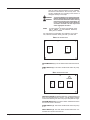
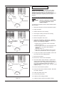
BEXT®-100
Control Panel
1
2
VAC
PUMP
Figure 4
VACUUM SWITCH (1 ): The vac switches illuminate when turned
on.
PUMP SWITCH (2): This switch will illuminate when the pump
is on.
BEXT®-100H
Control Panel
1
LOCATOR
2
3
4
VAC
PUMP
HEAT
Figure 5
CIRCUIT LOCATOR (1): When this light is on, it indicates that cord
#2 is on a separate line from cord #1. Cord #2 supplies voltage
to the heater allowing it to heat to the proper temperature range.
VACUUM SWITCH (2): The vacuum switch will illuminate when
the vacuum motor is turned on.
PUMP SWITCH (3): This switch will illuminate when the pump
is on.
HEAT SWITCH (4): The heat switch will illuminate when it is
activated and will turn the heater on.
Page
16
Clarke® BEXT®
-100, 100H 150H, 300HV Operator's Manual
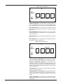
BEXT®-150 H Control Panel
1
LOCATOR
2
MODE
3
4
5
6
VAC 1
VAC 2
PUMP
HEAT
Figure 6
CIRCUIT LOCATOR ( 1 ): When this light is on, it indicates that cord
#2 is on a separate line from cord #1. Cord #2 supplies voltage
to the heater allowing it to heat to the proper temperature range.
HEAT MODE LIGHT ( 2 ): This light will only illuminate when the
heater is heating and will turn off when it reaches operating
temperature.
VACUUM SWITCH ( 3 & 4): Each switch turns on one vac motor.
turn both switches on for maximum lift. The vac switches illuminate when turned on.
PUMP SWITCH ( 5 ): This switch will illuminate when the pump is
on.
HEAT SWITCH ( 6 ) : The heat switch will illuminate when it is
activated and will turn the heater on.
BEXT®-300
HV Control Panel
5
Upholstery
LOCATOR
6
MODE
1
2
3
4
VAC
PUMP
CARPET
HEAT
Figure 7
VAC ( 1 ) & PUMP ( 2 ) SWITCHES: These switches are powered
by cord #1 (4" red band). Switches are on when illuminated.
CARPET / UPHOLSTERY SWITCH ( 3 ): This switch is also
powered by cord #1. The carpet setting (down position) is high
pressure (approximately 300 psi). The upholstery setting (up
position) is low pressure (approximately 75 psi). NOTE: Switch
does not illuminate.
HEAT SWITCH ( 4): Turning on this switch (switch illuminates
when on) turns the heater on.
GREEN CIRCUIT LOCATOR LIGHT ( 5 ): When this light is illuminated, it confirms that the machine is on two separate circuits.
See previous page for additional information on the circuit
locator.
HEAT LIGHT MODE ( 6 ) : The light will only illuminate when the
heater uis heating and will turn off when it reaches operating
temperature.
Page
18
Clarke® BEXT®
-100, 100H 150H, 300HV Operator's Manual
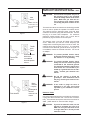
INSTRUCTIONS FOR CONNECTION TO THE
POWER SUPPLY AND ELECTRICAL GROUND - 120 V
CAUTION:
Plate
Screw
Outlet must be
connected to
the electrical
ground
Ground Pin
Figure 7
Tornillo
de la
placa
Terminal de
tierra
El tomacorriente
debe estar
conectado al
borne de puesta
a tierra
Figura 7
This machine will operate only on an
AC frequency and on the specified
electrical voltage shown on the nameplate. Make sure you have the correct frequency and voltage before
connecting the power cord to an outlet.
This machine must be connected to an electrically grounded
circuit in order to protect the operator from electric shock.
This machine has an approved power cord with three
conductors as well as a plug with three terminals. Connect
the plug to a three holed receptacle. For maximum
protection against electric shock, use a circuit that is
protected by a ground fault circuit interrupter.
This machine uses a 120 volt AC 50/60 cycle electrical
circuit. Make sure you have the correct frequency and
voltage before connecting the power cord to an outlet. The
machine has a plug as shown in Figure 7. If a receptacle
connected to the electrical ground as shown in Figure 7 is
not available, contact an electrical contractor. Do not use
an adapter.
WARNING: To prevent possible electric shock,
protect the machine from rain. Keep
the machine in a dry building.
WARNING: To prevent possible electric shock,
always use a 3-wire electrical system
connected to the electrical ground.
For maximum protection against electrical shock, use a circuit that is protected by a ground fault circuit interrupter. Consult your electrical contractor.
WARNING: Do not cut, remove, or break the
ground pin. If the outlet does not fit
the plug, consult your electrical contractor.
Borne
mâle de
la prise
Le réceptacle
doit être
connecté à la
masse
Fiche de terre
Figure 7
WARNING: If the cords or plugs are worn or
damaged in any way, have them
replaced by an authorized service
person.
Extension Cords
Use only an approved extension cord with three conductors,
a plug with three terminals and a three-holed connector
body. This machine has a power cord with a wire size of 12
AWG. (AWG stands for American Wire Gauge).
CAUTION:
Page
20
If you use an extension cord, use one
that has a minimum wire size of 12
AWG. Be sure your extension cord is
no longer than 50 ft. Do not join two
extension cords.
Clarke® BEXT®
-100, 100H 150H, 300HV Operator's Manual
MACHINE OPERATING INSTRUCTIONS
Area 1 See figure 8
How to Clean an Area of Carpet See Figure 8A
Superficie 1. Vea la Figura 8
WARNING:
Zone 1 Voir figure 8
Do not use water that is hotter
than 120°F (48°C).
To clean an area of carpet, follow this procedure:
Vacuum only,
after cleaning
each area for
maximum
water removal
Para eliminar la
mayor cantidad
de agua posible
sólo realice la
aspiración
después de
limpiar cada
superficie
Figure 8A
Figure 8B
Aspiration
seulement,
après nettoyage
de chaque zone
pour une
élimination
maximum de
l'eau
1. Start the pump for the solution and the motor for the
vacuum on the extractor.
2. Begin at the right-hand corner of the carpet.
3. Hold the floor tool at the angle that gives the best
vacuum seal between the tool and the carpet.
4. Apply pressure to the lever for solution release. Pull
the tool toward you at a slow, steady speed. To
remove as much solution as possible, release the
lever before you stop moving backward. Push tool
away over the same area while moving tool to next
position. (Repeat process)
5. To clean the edge of a room, move the tool along the
baseboard until the edge of all the carpet is cleaned.
6. To clean a small area of carpet, clean the carpet in
sections three feet square. As you make more
passes, repeat one inch of the area already cleaned.
7. To remove more liquid from the carpet, make passes
over the area already cleaned, but do not apply
pressure to the lever for the solution.
How To Clean A Larger Area Of Carpet See Fig. 8B
To clean a larger area of carpet, follow this procedure:
1. Begin at the right-hand corner of the carpet.
2. Make a pass halfway along the edge of the carpet.
Pull the tool backward at a steady speed.
3. Move to the edge of the carpet. Make another pass
next to your first pass.
4. As you make more passes, repeat one inch of the
area already cleaned. If you use a power brush tool,
repeat one inch of the area already cleaned by the
brush. Make each pass four inches different in length
to prevent making a line in the center of the carpet.
5. Make more passes until half of the carpet is cleaned.
To remove more liquid from the carpet, make passes
over the area already cleaned, but do not apply
pressure to the lever for the solution.
6. Move to the right-hand corner of the part of the carpet
not yet cleaned.
7. Make a pass halfway along the edge of the carpet.
8. As you make passes, repeat one inch of the area
already cleaned.
9. Make more passes until all of the room is cleaned.
CAUTION:
Page
22
Clarke® BEXT®
Clarke will not be held liable for damage
to the carpet, or poor results because of
the operator's lack of ability.
-100, 100H 150H, 300HV Operator's Manual
MAINTENANCE
WARNING: Maintenance and repairs must
be done by authorized personnel only. Keep all fasteners tight.
Use only genuine Clarke parts.
WARNING: Do not operate this machine unless it is completely assembled.
NOTE: For maintenance of the floor tools read the
manual given with the tools.
After Each Use of the Machine
1. Remove unused cleaning solution from the solution tank, by placing the end of the vacuum hose
in the solution tank. Start the vacuum motor.
Stop the motor when the tank is empty.
2. To prevent damage to the valves and jets, flush
one gallon of clean water through the solution
system and the tools.
3. Disconnect the power cord from the outlet.
4. For optimum performance, flush the machine with
clear water at the end of each working day. Once
a month, minimum, run a flushing compound
through the machine to cut any alkaline build-up
that may have formed.
5. Lubricate wheels, casters, and hinges as needed.
The pump and vacuum motor do not require any
maintenance.
6. The body can be cleaned with a general allpurpose detergent and protected with a silicone
type product. The quick-disconnects should be
lubricated with silicone, also.
7. Prior to each job, inspect the holding tank filter
and the recovery tank float filter for hair and dirt.
The drain valve should also be inspected regularly
and kept free of any debris or build-up.
8. Drain the recovery tank and dispose of properly.
9. Rinse the recovery tank with clean water.
10. Use a dry cloth to wipe the tools and both tanks,
inside and out.
11. Apply a small amount of silicone lubricant to the
quick-disconnect fittings. To prevent damage to
the O-rings, do not use an oil lubricant.
Page
24
Clarke® BEXT®
-100, 100H 150H, 300HV Operator's Manual
MAINTENANCE (CONT)
How To Prevent Damage From Freezing Temperatures
To prevent damage from freezing temperatures follow
this procedure:
1. Use the vacuum hose to remove all the solution
from the clean solution tank.
2. Connect the solution hose to the extractor and a
floor tool.
3. Put approximately 1 quart of antifreeze solution in
the solution tank.
Figure 9a
4. Put the switch for the pump in the "ON" position.
5. Put the end of the floor tool in the recovery pail.
6. Press the lever on the floor tool to activate the
pump.
7. Make sure the solution runs through the system.
8. Release the lever on the floor tool to stop the
pump.
9. Flush the antifreeze solution from the system
before using the extractor.
WARNING: Electrical repairs must be done by
authorized personnel only.
WARNING: After electrical repairs are done to
the machine, the machine must be
tested for electrical safety.
Figure 9b
How To Get Access To The Pump and Vacuum
Motor
To get access to the pump and the vacuum motor,
follow this procedure (see figures 9a & 9b):
1. Empty both tanks.
2. Unlatch tanks from base.
3. Tilt tanks back.
4. Disconnect hoses from tanks.
5. Open up for service.
Page
26
Clarke® BEXT®
-100, 100H 150H, 300HV Operator's Manual
MAINTENANCE
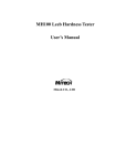
Maintenance Of The Motor
This machine has a vacuum motor that uses carbon
brushes. The carbon brushes in the motor must be
checked every three months, or every 500 hours of
operation, whichever comes first. If either of the brushes
is shorter than 3/8 inch, replace both of the carbon
brushes.
GOOD
UNEVEN
SMALL
HOLES
GOOD
A
B
GOOD
HIGH MICA
How To Check The Commutator And The Carbon
Brushes
WARNING:
Electrical inspections must be made
by a person authorized to make
electrical repairs.
To check the commutator and the carbon brushes follow
this procedure:
C
1. Disconnect the power cord from the electrical outlet.
2. Empty both tanks.
3. Unlatch tanks from lower housing.
4. Lift the upper housing from the lower housing.
5. Disconnect the ground wire.
6. Remove the plastic motor cover.
AGUJEROS
EN BUEN PEQUEÑOS
ESTADO
A
IRREGULAR
EN BUEN
ESTADO
B
MICA ALTA
EN BUEN
ESTADO
C
7. Inspect the commutator. See figure 10. Take the
machine to a Clarke authorized repair location if you
see any of the following conditions:
a. Small holes in the surface of the commutator.
See "A" in figure 11.
b. Uneven color. Look for an even dark brown color.
Clean areas or very dark areas indicate a
problem.
See "B" in figure 11.
c. High mica. The mica insulation must be lower
than the commutator bars. See "C" in figure 11.
8. To check the carbon brush assemblies, remove the
two screws from the holding bracket.
9. Remove the brackets.
10. Remove the carbon brush assemblies.
INÉGAL
PETITS TROUS
CORRECT
CORRECT
A
12. Put the motor brushes in position.
B
MICA ÉLEVÉ
CORRECT
11. Check the carbon brush assembly. Replace both
carbon brush assemblies if either carbon brush is
shorter than 3/8 inch. If either brush is shorter than ½
inch, order replacement brushes. Be ready to
replace both carbon brushes earlier than the normal
inspection time.
13. Using the two screws, install the bracket that holds
the carbon brushes.
14. Install the plastic motor cover.
C
15. Connect the ground wire.
16. Install the motor holding bracket.
Figure 10
Page
28
17. Install the lower housing to the upper housing.
Clarke® BEXT®
-100, 100H 150H, 300HV Operator's Manual
HOW TO CORRECT PROBLEMS IN THE MACHINE
Problem
The machine will not run.
Cause
Action
1. The machine has no power.
1. Make sure the machine is connected to the
correct frequency and voltage, and all connections are tight.
Make sure the plug is in the electrical outlet.
There is no suction.
2. The power cord is damaged.
2. Contact an authorized service person to replace
the cord.
1. The vac motor does not run.
1. Put the switch for the vacuum in the "I" position.
2. The vac motor switch is defective.
2. Contact an authorized service person.
3. There is a loose motor connection.
3. Contact an authorized service person.
4. There is an obstruction in the vacuum
hose.
5. The recovery tank is full.
4. Remove the obstruction.
6. The dome gasket is worn or damaged.
6. Contact an authorized service person to replace gasket.
5. Remove the liquid from the tank.
7. The internal vac hose is damaged
or stopped.
7. Contact an authorized service person.
8. The dome is damaged
8. Replace the dome.
9. The motor brushes are worn.
9. Replace the motor brushes.
10. Drain gate is open.
10. Close drain gate.
11.Seals are damaged.
11.Contact an authorized service person.
1. The switch is in the "OFF" position.
1. Put the switch in the "I" position.
2. The pressure switch is damaged.
2. Contact an authorized service person.
3. The pump motor will not run.
3. Contact an authorized service person.
4. The pump motor brushes are worn.
4. Contact an authorized service person.
5. The quick disconnect fitting is dirty
or stopped.
5. Contact an authorized service person.
6. The solution hose is bent.
6. Straighten the hose. Replace if damaged.
7. The pump is worn.
7. Contact an authorized service person.
8. The pump switch is defective.
8. Contact an authorized service person.
9. The pump connections are loose.
9. Contact an authorized service person.
10.The pump intake and oulet valves are
worn.
11.The thermol protector is open.
10.Contact an authorized service person.
12.The solution tank is empty.
12.Fill the solution tank.
13.The intake screen is dirty.
13.Clean the screen.
14.The rectifier in the pump motor is bad.
14.Contact an authorized service person.
The solution tank leaks.
1. The tank is damaged.
1. Contact an authorized service person.
The recovery tank overflows.
1. The float is dirty or damaged.
2. There is too much foam.
3. The float gasket is dirty or damaged.
1. Clean the float. Replace if damaged.
2. Put defoamer in the solution. Order P/N 398420.
3. Clean the gasket. Replace if damaged.
There is no pressure.
Page
30
11.Contact an authorized service person.
Clarke® BEXT®
-100, 100H 150H, 300HV Operator's Manual
BEXT®-100, 100H, 150H, 300HV
Extractor
Section II
Parts and Service Manual
(70416A)
Clarke® BEXT®-100,
100H 150H, 300HV Operator's Manual
Page 33
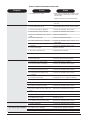
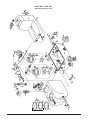
Clarke® BEXT®-100, 120V
Assembly Drawing 7/06
Page
34
Clarke® BEXT®
-100, 100H 150H, 300HV Operator's Manual
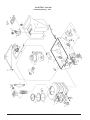
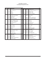
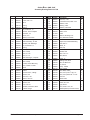
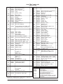
Clarke® BEXT®-100, 120V
Assembly Drawing Parts List 7/06
Ref #
1
Part No.
53876A
Description
Drain Gate
Qty
1
Ref #
34
Part No.
80335A
Description
Lock Nut, ¼-20
2
3
80331A
52636A
Screw, 8-32 x 5/8"
Latch
4
2
39
40
53885A
53895A
Quick Disconnect, Male ¼ PT
Washer, Fiber
1
3
4
4A
53877A
53878A
O-Ring
O-Ring
1
1
40A
40B
54066A
80341A
Bushing, Fiber
Washer, Flat Brass
1
1
4B
5
80332A
53861A
Nut, Aluminum, ½"
Vacuum Tank Complete
1
1
41
42
52763A
52675A
Louver 3", includes screws
Strike, Latch
3
2
6
7
53879A
53880A
Hose Bar, 1½"
Elbow, PVC
1
1
43
44
52675A
Label
Reducer, Bushing PVC
2
1
8
9
53881A
53882A
Gasket, Lid Vacuum
Lid, Clear 6" w/ring
1
1
45
48
53798A
53898A
Cord, Retainer Flexible
Axle, Rod 17"
1
1
9A
10
53883A
53884A
Chain Assembly, for lids
Manifold, with Ball/Cage
2
1
49
50
53867A
53899A
Wheel, 8"
Axle, Cap
2
2
11
12
80332A
53877A
Nut, Aluminum 1½"
O-Ring
1
1
51
52
80335A
54069A
Lock Nut, ¼-20
Bracket, Axle
4
2
13
14
53880A
53887A
Elbow, PVC
Hose Clamp
1
4
53
54
80343A
53863A
Bolt, ¼-20 x 3/4"
Base, Black
12
1
15
15A
53888A
53889A
Hose, 2" x 21"
Hose, 2" x 2"
1
1
55
56
53866A
53862A
Castor, 3"
Holding Tank, Blue
2
1
20
22
53893A
53894A
Elbow
Gasket
1
1
57
58
53872A
54070A
Filter, 40 Mesh SS
Lid, Tinted
1
1
24
25
40954A
80334A
Vacuum Motor, 3-Stage
Washer, Flat
1
3
65
66
53869A
54071A
Pump, 100PSI
Hose Clamp
1
4
26
27
80335A
53896A
Lock Nut, ¼-20
Gasket, Vacuum
3
1
67
68
54072A
54073A
Hose Barb, Elbow
Hose, Pump Inlet 3/8 ID x 13"
2
1
28
29
80336A
80334A
Nut, Finish
Washer, Flat
3
3
69
77
54074A
53868A
Hose, Pump Outlet ID 3/8 x 22"
Switch Plate
1
1
30
31
80338A
53897A
Bolt, ¼-20 x 5"
Manifold, Vac Motor, Black
3
1
78
79
52842A
80345A
Switch, Rocker w/cover
Screw, #4 x 3/8"
2
5
32
52672A
Exhaust Flange
1
81
40637A
Cord, Power 12-3, 25"
1
Clarke® BEXT®-100,
100H 150H, 300HV Operator's Manual
Qty
8
Page 35
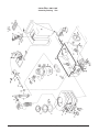
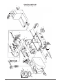
Clarke® BEXT®-100H, 120V
Assembly Drawing 7/06
Page
36
Clarke® BEXT®
-100, 100H 150H, 300HV Operator's Manual
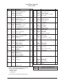
Clarke® BEXT®-100H, 120V
Assembly Drawing Parts List 7/06
Ref #
1
2
Part No.
53876A
80331A
Description
Drain Gate
Screw, 8-32 x 5/8"
3
4
52636A
53877A
Latch
O-Ring
4A
4B
53878A
80332A
5
6
Qty
1
4
Ref #
34
39
Part No.
80335A
80340A
Description
Lock Nut, ¼-20
Quick Disconnect, Male ¼ PT
2
1
40
40A
53895A
54066A
Washer, Fiber
Bushing, Fiber
3
1
O-Ring
Nut, Aluminum, ½"
1
1
40B
41
80341A
52763A
Washer, Flat Brass
Louver 3", includes screws
1
3
53861A
53879A
Vacuum Tank Complete
Hose Bar, 1½"
1
1
42
43
52675A
71194A
Strike, Latch
Label
2
2
7
8
53880A
53881A
Elbow, PVC
Gasket, Lid Vacuum
1
1
44
45
52675A
53798A
Reducer, Bushing PVC
Cord, Retainer Flexible
1
1
9
9A
53882A
53883A
Lid, Clear 6" w/ring
Chain Assembly, for lids
1
2
46
47
54067A
54068A
Dual Cord Circuit Board
Snap Track, Circuit Board Mounting
1
1
10
11
53884A
80332A
Manifold, with Ball/Cage
Nut, Aluminum 1½"
1
1
48
49
53898A
53867A
Axle, Rod 17"
Wheel, 8"
1
2
12
13
53877A
53880A
O-Ring
Elbow, PVC
1
1
50
51
53899A
80335A
Axle, Cap
Lock Nut, ¼-20
2
4
14
15
53887A
53888A
Hose Clamp
Hose, 2" x 21"
4
1
52
53
54069A
80343A
Bracket, Axle
Bolt, ¼-20 x 3/4"
2
12
15A
16
53889A
53890A
Hose, 2" x 2"
Heat Exchanger, complete
1
1
54
55
53863A
53866A
Base, Black
Castor, 3"
1
2
16A
17
53891A
See Misc. Parts List
Hose Clamp
1
56
57
53862A
53872A
Holding Tank, Blue
Filter, 40 Mesh SS
1
1
18
19
53892A
53870A
Bracket, Heater Mounting
Hose, Heater to outlet
1
1
58
65
54070A
53869A
Lid, Tinted
Pump, 100PSI
1
1
20
22
53893A
53894A
Elbow
Gasket
1
1
66
67
54071A
54072A
Hose Clamp
Hose Barb, Elbow
4
2
24
25
40954A
80334A
Vacuum Motor, 3-Stage
Washer, Flat
1
3
68
69
54073A
54074A
Hose, Pump Inlet 3/8 ID x 13"
Hose, Pump Outlet ID 3/8 x 48"
1
1
26
27
80335A
53896A
Lock Nut, ¼-20
Gasket, Vacuum
3
1
70
77
80344A
54075A
Lock Nut
Switch Plate
28
29
80336A
80334A
Nut, Finish
Washer, Flat
3
3
78
79
53842A
80345A
Switch, Rocker w/cover
Screw, #4 x 3/8"
3
30
31
80338A
53897A
Bolt, ¼-20 x 5"
Manifold, Vac Motor, Black
3
1
80
81
54076A
40637A
Light, Green
Cord, Power 12-3, 25"
1
2
32
52672A
Exhaust Flange
1
NI
54077A
Heat Repair Kit (incl. cutout & thermo switch)
Clarke® BEXT®-100,
100H 150H, 300HV Operator's Manual
Qty
8
1
1
Page 37
8
8A
86
Clarke® BEXT®-150H, 120V
Assembly Drawing 11/05
Page
38
Clarke® BEXT®
-100, 100H 150H, 300HV Operator's Manual
Clarke® BEXT®-150H, 120V
Parts List 3/06
Ref #
1
1A
2
3
4
4A
4B
5
*6
*7
8
8A
8B
9
9A
10
Part No.
59721A
53606A
962929
52636A
837304
Description
Valve-Drain
Elbow-45 Degree, Drain
Screw, 10-32 x 3/8
Latch, Tank
O-Ring (Small)
920797
30322A
690212
692701
55674A
34288A
692409
85613A
81109A
52806A
2
1
1
1
1
1
1
1
1
1
11
12
13
14
15
15A
16
16A
17
18
19
20
20A
21
22
23
24
24A
25
26
27
27A
28
29
30
31
32
33
34
35
36
37
38
920797
Nut Drain Valve Lock
Tank, Recovery
Adaptor Asm.-Vac Hose
Elbow - 90 Degree
Lid 6" Clear
Gasket**
Chain-Cover
Screw, 8-32 x 7/8 Pan Hd
Nut, Hex Elastic Lock
Vac Manifold Asm. (incl. 10, 10A,
11, 12, 13)
Nut Drain Valve
30323A
872010
52666A
52667A
52566A
732870
Elbow, Vac Manifold
Hose clamp
Hose Vacuum Tank
Hose, Vacuum to Manifold
Heater, Complete
Hosebarb
1
1
1
1
1
1
30323A
52993A
52992A
87026A
81102A
44906A
40833A
30197A
52670A
85742A
87026A
Hose, Braided Heater
Washer, Brass
Washer, Fibre
Nipple, ¼ NPT SS
Busing, Fiber
Thermostat, Heater
Elbow, Brass
Coupling
Washer ¼
Nut, ¼ -20
Motor, Vac
Brush, Carbon
Gasket, Vac Motor
Vacuum, Manifold
Screw, ¼-20
Washer
1
1
1
1
1
1
1
1
6
1
1
2
2
2
6
6
170030
Hosebarb
1
52995A
52834A
53639A
52671A
Handle, Lifting
Qty
1
1
1
2
1
2
Ref #
39
40
41
42
43
44
45
46
47
48
49
50
51
52
53
54
55
56
57
58
59
60
61
62
63
64
65
66
67
68
69
70
71
72
73
74
75
76
77
78
79
80
81
82
83
84
85
*86
Part No.
962098
52840A
52672A
52673A
52674A
Description
Screw, ¼ -20 x 3/4
Quick Disconnect
Flange, Exhaust
Louvre, (includes hardware)
Strike, Latch
Qty
1
1
1
3
2
52675A
52676A
40661A
52664A
61388A
52471A
920346
40637A
61339A
170915
30324A
52470A
30195A
52841A
52677A
53558A
50248A
51206A
170030
Reducer, PVC
Retainer, Cord
Sensor, Dual Cord
Snap Track, 4"
Axle, Wheel
Wheel, 10"
Axle, Cap
Cord, Power
Pin, Hinge
Screw, ¼-20 x 3/4
Housing, Lower
Castor, 4" Grey
Holding Tank
Filter, Inlet
Adaptor, Inlet Screen
Solution, Tank Lid
Hose Clamp
Pump, Solution
Hosebarb, 3/8 PT x ¼ Barb
2
2
1
1
1
1
2
1
2
8
1
2
1
1
1
1
1
1
1
30326A
962454
52678A
Hose, Inlet
Hose, Outlet
Switch Plate
1
1
1
52668A
Light, Green
2
52842A
52843A
Switch, Vacuum / Pump
Switch, Pump
3
1
30635A
52679A
962454
Gasket, Base
Cord Wrap
Screw, ¼-20 x 1
1
2
2
693406
Gasket
1
1
* Items 6, 7 & 86 must be ordered as a set when
replacing any original #6 Adapter and
3 - 85522A Screws
1 - 962109 Screw
1 - 920296 Nut
Part #
52847A
Miscellaneous Assemblies/ Parts
Heat Repair Kit w/ Thermostat and Cutout Asm.
** Item 8A must be used with any lid replacement.
Clarke® BEXT®-100,
100H 150H, 300HV Operator's Manual
Page 39
Page
40
8
8B
1A
1
6
4
9A
9
Clarke® BEXT®
4B
104
8A
11
4A
7
10
4
81
81
82
13
80
15
73
5
22
Pri
mi
72
28
e
32
s
Ho
30
31
24A
24
21
86
97
ng
26
102
26A
27
70A
79
78
16
14
40
25
70B
65
71
17
34
47
38
90
98
23
33
70 26A
18
39
96
19
22
91
91 29
97 89
86 97
100
19A
20-
99
91
101
63
103
95
68
67
66
35
23
65
46
37
36
91
24
93
92
90
86
85
53
89
88
87
29
91
85
64
55
49
54
61
94
52
91
84
59
58
56
53
91
57
2
3
77
75
76A
76
63A
62
63
Clarke® BEXT®-300HV, 120V
Assembly Drawing 11/05
-100, 100H 150H, 300HV Operator's Manual
Clarke® BEXT®-300HV, 120V
Parts List 3/06
Ref #
1
1A
2
3
4
4A
4B
5
*6
*7
8
8A
8B
9
9A
10
11
12
13
14
15
16
17
18
19
19A
20
21
22
23
24
24A
25
26
26A
27
28
29
30
31
32
33
34
35
36
37
38
39
40
41
42
43
44
46
47
49
50
51
52
53
Part No.
59721A
53606A
962929
52636A
837304
Description
Drain Gate (see misc)
Spout, Drain Gate
Screw, 10-32 x 3/8, SS
Latch
O-Ring (small)
Qty
1
1
4
2
3
920797
30322A
690212
692701
55674A
692409
34288A
85613A
81109A
Drain Valve
Tank, Recovery
Adaptor
PVC Elbow, 1½"
Lid & Ring, 6"
Chain Assemly, 8"
Gasket**
Screw, 8-32 x 7/8"
Nut, 8/32, SS Nylock
2
1
52806A
Vacuum Mainfold, Incl. Ball & Cage 1
(includes 10, 10A, 11, 12 and 13)
872010
52665A
52365A
52566A
52834A
Hose Clamp
Hose, Rubber
Hose Clamp
Heat Exchanger Mount
Heat Exchanger, Complete
Thermostat, Heat Switch (see misc)
61350A
52988A
52989A
851144
52991A
30323A
52992A
52993A
Hose, 26", High Pressure ¼ I.D.
Quick Disconnect, Open 1/8", PT
Quick Disconnect, Male, 1/8" PT
Bushing Brass, ¼ MPT x 1/8 FPT
Coupling
Hose, Braided, SS
Washer, Brass
Washer, Fiber
52995A
Bushing, Fiber
52997A
52998A
61351A
52835A
52836A
Lock Nut, 5/16"
Washer, 5/16"
Screw, 10-32 x 5/8", SS
Nut, 5/16"
Washer, 5/16"
Bolt, 5/16 x 4"
PVC Sleeve, 3"
PVC Elbow, 90°, 1½", Slip
Mount Plate
Gasket (Vacuum Motor)
Vacuum Motor (120V)
1
1
1
2
1
1
1
1
2
2
1
1
1
1
1
1
Part No.
Description
40661A
52664A
52471A
920346
61339A
52679A
170915
87026A
61338A
52673A
30635A
40750A
52470A
Dual Cord Sensor, Circuit Board
Mount, Dual Cord Sensor
Wheel, 10"
Axle Cap
Hinge Rod, ¼ x 3½", SS
Cord Wrap
Screw, 1/40-20 x 1", SS
Washer, ¼, SS
Axle, 18"
Louver, 3"
Gasket, Base
Housing, Lower
Castor, 4" x 1"
Bolt, ¼-20 x 3/4"
Quick Disconnect, Male ¼" PT
Priming Hose
Quick Disconnect, Female ¼ PT
Latch Strike
Handle, Lifting
Screw, Flathead
Tank, Solution
Filter, Pump Inlet
Adapter, Inlet Screen
Lid, Solution Tank
Switch, Pump & Vacuum
Switch, Heat
Panel, Control
Green Light
Screw, #4 x 3/8 SS
Elbow 90°, ¼ PT
Hose Barb, ¼ PT x ½" Hose
Hose Clamp
Hose, Pump Inlet, ½" x 14"
Pump, No Fittings (see misc.)
"T" Brass, ¼ PT
Nipple, SS, ¼ PT
Elbow Brass, ¼ MPT x ¼ FPT
Quick Disconnect, Male ¼ PT
52840A
61314A
52565A
52674A
52671A
962098
30338A
52841A
52677A
53558A
52842A
52843A
52678A
52668A
53639A
52171A
50248A
170066
170086
170040
696801
697501
170030
53173A
53174A
690209
52844A
53175A
52837A
693406
Part #
52848A
40637A
PVC Reducer
Lock Nut
Power Cord, 12/3, 25 ft.
2
52676A
Cord Retainer, Water Tight
2
52846A
52849A
53389A
52845A
* Items 6, 7 & 104 must be ordered as a set when replacing any original
#6 Adapter and: 3 - 85522A Screws, 1 - 962109 Screw, 1 - 920296 Nut.
** Item 8B must be used with any lid replacement.
Clarke® BEXT®-100,
Ref #
54
55
56
57
58
59
61
62
63
63A
64
65
66
67
68
69
70
70A
70B
71
72
73
75
76
76A
77
78
79
80
81
82
84
85
86
87
88
89
90
91
92
93
94
95
96
97
98
99
100
101
102
103
* 104
100H 150H, 300HV Operator's Manual
52847A
Qty
Plug, Brass
Reducing Nipple, ¼ MPT x 1/8 MPT
Hose Barb, Brass ¼ PT x 3/8 Hose
Bypass Valve (see misc.)
Hose, 3/8" x 8"
Hose Barb, Brass 1/8 PT x 3/8 Hose
Solenoid (120V), NC
Hose, Pump Bypass, 3/8" x 14"
Motor, for Pump (AC, 120V)
Gasket, Swivel
1
1
2
2
2
2
2
2
1
1
1
2
1
1
2
1
4
1
1
1
3
1
1
2
8
1
1
1
Miscellaneous Assemblies/ Parts
Bypass Rebuild Kit
Valve/O-Ring Kit
Plunger & Seals Kit
Pump Complete (no motor or solenoid)
Pump Complete with Solenoid
Pump & Motor Complete with Solenoid
Bearing/Cam Asm. (for pump)
Drain Gate Complete w/ O-Rings, Nut & Spout
Heat Repair Kit w/Thermostat & Cutout Asm.
Label, Clarke
Page 41
Clarke®
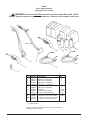
BEXT -100 Accessories
Drawing & Parts List 3/06
®
WARNING: Do not use Bext 100 accessories on heated units (Bext 100H, 150H &
300HV). Injury to operator or bystanders could occur. Damage to the machine could occur.
4A
6
3
7
8
9
11
4
10
2
5
1**
Ref
1
2
3
4
4A
5
6
7
8
9
10
11
ASM
NI
Part No.
30108A
59231A
59230A
61393A
30496A
59232A
59228A
398426
398425
398427
55183A
52953A
55173A
682408
Description
Qty
Adaptor, 2" to 1½
1
RM-4P Tool Assembly
1
RM-8P Tool Assembly
1
RM-12M Tool Assembly
1
Hose Asm. , Squeegee
1
Hide-A- Hose 10'
1
RM-4M Tool Assembly
1
Defoamer
*1 case
Extractor, Concentrate
*1 case
Traffic Lane/Spot Cleaner
*1 case
Hide-A-Hose 20'
1
General Purpose Spot Cleaner
1 case
4" Hand Tool and 10' Hose Asm.
1
Coupler, 1½" Hose Connector
1
* 4, 1 gallon bottles
NOTE: u indicates a change has been made since the last
publication of this manual.
Page
42
Clarke® BEXT®
-100, 100H 150H, 300HV Operator's Manual
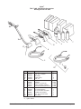
BEXT
®
Clarke®
100H, 150H Detailer Accessories
Drawing & Parts List 6/04
1B
1B
12A
1A
1B
3
4
5
6
7
12
1C
8
3
2
1
1**
2
9 11
10
Ref
1
1A
1B
1C
2
3
4
5
6
7
8
9
10
11
12
12A
Part No.
61394A
30496A
52544A
52996A
52469A
52833A
398426
398425
398427
52953A
52832A
30229A
10386A
682408
52514A
53557A
Description
12" Wand
Hose Asm., Solution
Valve Body
Nozzle, Spray
Hose 15'
Tool, 3½ HP
Defoamer
Extractor, Concentrate
Traffic Lane/Spot Cleaner
General Purpose Spot Cleaner
Tool, 4" Closed
15" Hose Extension
Kit, 15" Hose Ext. w/Coupler
1.50 Dia. Hose Coupler
Tool, 31/2 Closed Detail
Valve, Body
Qty
1
1
1
2
1
1
*1 case
*1 case
*1 case
1 case
1
1
1
1
1
1
* 4, 1 gallon bottles
Clarke® BEXT®-100,
100H 150H, 300HV Operator's Manual
Page 43
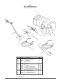
Clarke®
BEXT® 300HV Accessories
Drawing & Parts List 1/04
1B
1B
1A
1B
1C
8
2
1**
9
11
10
Ref
1
1A
1B
1C
2
3
4
5
6
7
8
9
10
11
Part No.
61395A
30496A
52544A
52996A
52469A
52833A
398426
398425
398427
52953A
52832A
30229A
10386A
682408
Description
12" Wand
Hose Asm., Solution
Valve Body
Nozzle, Spray
Hose 15'
Tool, 3½ HP
Defoamer
Extractor, Concentrate
Traffic Lane/Spot Cleaner
General Purpose Spot Cleaner
Tool, 4" Closed
15" Hose Extension
Kit, 15" Hose Ext. w/Coupler
1.50 Dia. Hose Coupler
Qty
1
1
1
2
1
1
*1 case
*1 case
*1 case
1 case
1
1
1
1
* 4, 1 gallon bottles
Page
44
Clarke® BEXT®
-100, 100H 150H, 300HV Operator's Manual
Clarke®
BEXT -150H, 120V
Wiring Diagram 10/01
®
BEXT-150H EXTRACTOR
WIRING DIAGRAM
120V
BLACK
CORD 1
WHITE
GROUND
ORANGE
VAC 1
VAC 2
BLACK
SW
WHITE
VACUUM
VACUUM
SW
ORANGE
WHITE
FAN
BLUE
SW
PUMP
DUAL
CORD
SENSOR
CIRCUIT
BOARD
P1
P2
P4
P3
BYPASS
SWITCH
P6
P7
P5
BLACK
MODE
LIGHT
BLACK
HEATER
WHITE
TC
BLACK
LOCATOR
LIGHT
CORD 2
GROUND
10/04/01
Page
46
Clarke® BEXT®
-100, 100H 150H, 300HV Operator's Manual