1
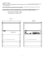
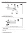
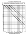
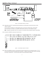
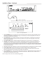
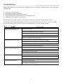
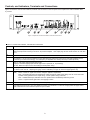
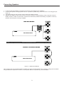
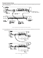
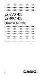
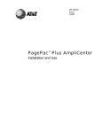
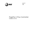
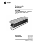
Issue 3
PagePac Plus AmpliCenter
V-5328300A - (D300A)
V-5328100A - (D100A)
V-5328040 - (D40)
Installation and Use
IMPORTANT SAFETY INFORMATION:
1. Read these instructions.
13. Unplug this apparatus during lightning storms or when
unused for a long period of time.
2. Keep these instructions.
14. Refer all servicing to qualified service personnel.
Servicing is required when the apparatus has been
damaged in any way, such as when the power supply
cord or plug is damaged, liquid has been spilled,
objects have fallen into the apparatus or the apparatus
has been exposed to rain or moisture and does not
operate normally or has been dropped.
3. Heed all warnings.
4. Follow all instructions.
5. Do not use this apparatus near water.
6. Clean only with dry cloth.
7. Do not block any ventilation openings. Install in
accordance with the manufacturer’s instructions.
Precautionary Information
“WARNING: To Reduce The Risk of Fire Or Electric
Shock, Do Not Expose This Apparatus To Rain Or
Moisture.”
8. Do not install near any heat sources such as
radiators, heat registers, stoves or other apparatus
(including amplifiers) that produce heat.
9. Do not defeat the safety purpose of the polarized or
grounding-type plug. A polarized plug has two
blades with one wider than the other. A grounding
type plug has two blades and a third grounding
prong. The wide blade and the third prong are
provided for your safety. If the provided plug does
not fit into your outlet consult an electrician for
replacement of the obsolete outlet.
CAUTION
RISK OF ELECTRIC SHOCK
DO NOT OPEN
CAUTION: To reduce the risk of electric shock,
Do not remove cover.
No user serviceable parts inside.
Refer servicing to qualified service personnel.
10. Protect the power cord from being walked on or
pinched particularly at plugs, convenience
receptacles and the point where they exit from the
apparatus.
This symbol indicates that dangerous
voltage constituting a risk of electric
shock is present within this unit.
11. Only use attachments/accessories specified by the
manufacturer.
This symbol indicates that there are
important operating and maintenance
instructions in the literature accompanying
this unit.
12. Use only with the cart, stand, tripod, bracket or
table specified by the manufacturer or sold with the
apparatus. When a cart is used, use caution when
moving the cart/apparatus combination to avoid
injury from tip-over.
1
947159
Installation Steps
1. Mount the PagePac® Plus AmpliCenter to a 19 inch rack (Figure 1 & 2). Set 115/230 V Switch on rear to proper
voltage (D300A Only).
Note: If installed next to other equipment, including the PagePac Plus Controller and Zone Expansion Units, leave at
least four inches space above and below for proper ventilation.
PRIOR TO TURNING ON POWER CHECK SPEAKER WIRING: MAKE SURE WITH AN IMPEDANCE METER THAT FROM
EITHER SPEAKER WIRE TO CONDUIT BUILDING GROUND IS OPEN AND ACROSS SPEAKER TERMINALS IS:
•
•
•
16 Ohms @ 1kHz for V-5328300A - (D300A)
49 Ohms @ 1kHz for V-5328100A - (D100A)
122 Ohms @ 1kHz for V-5328040 - (D40)
VALCOM
VALCOM
AMPLICENTER D300A
Figure 1. Rack Mounted Hardware (Front View)
Figure 2. Rack Mounted Hardware (Rear View)
2
Installation Steps -Continued
2. Connect music input wires to Left, Right, and Ground terminals if stereo, or Left and Ground if not (see Figure 3).
Figure 3. Music Input Connections on AmpliCenter
Note: The optional audio background music source can be a line level output from a CD or tape player, AM,
FM or commercial radio or other audio device.
3. Connect speaker cable to AmpliCenter (see Figure 4).
DO NOT connect speaker wires with AmpliCenter power plug connected!
Figure 4. Speaker Connection on AmpliCenter
Note: If more than one speaker cable is routed to the AmpliCenter, a connector block may be necessary.
Refer to sample wiring diagrams (page 9 - Figure 11). Consult the 70V wire gauge guide (page 4 – Figure 5) for
more specific information.
4. Set the AmpliCenter Telephone Mode Selection Switch (page 5 - Figure 7) to match the page output type of your
telephone system.
5. Connect host telephone system to Amplicenter (page 5 - Figure 6).
6. Insert power cord into AmpliCenter and into wall outlet (page 6 - Figure 8).
7. Test paging zone served by the AmpliCenter.
3
70 VOLT SPEAKER WIRING LIMITATION CHART
Instructions: Determine the combined output in watts for all speakers on a line. Find that value
at the bottom of the chart. Follow the nearest vertical line up to its intersection with a diagonal
wire size line. Follow the horizontal line nearest the intersection to the left side of chart. Read
the maximum length in feet from the feet line.
Figure 5. Wiring Limitation Chart
4
Installation Steps -Continued
VALCO M
Figure 6. Host Telephone System Connection
Note: Connect the 4-wire RJ-11 type plug (used with telephones) to the Page Input connector (far right) or use the
“Page In” terminals.
Use Tip and Ring if installing to an existing paging system (line level low voltage output), VOX activated.
Use Tip and Ring if connecting to a Loop Start or Ground Start interface port in host telephone system.
With a microphone and preamp, hook the mic switch to C1 and Gnd, and the microphone output to Tip and Ring.
Note: Mic requires V-9939A for preamp and contact closure.
Figure 7. Host Telephone System Connection
Note: Refer to the Definitions on page 11 to determine the page line output type for your telephone system. For C.O.
Line Port or PBX Trunk Port, the setting will be Loop Start. For Page Port with Dry Contact Closure, the setting
will be Dry Loop 600 Ohm. You can also check with your telecommunication manager.
5
Installation Steps - Continued
VALCOM
Figure 8. Power Cable
Note: Do not use extension cords or plug into locally, “safety-fused” outlets.
Figure 9. Test Page Adjustments
1. Adjust LOW FREQ Cut Off : This control cuts out the low frequency bass so that horns and small speakers are not
over-driven and distorted by excessive bass energy. Cut off frequency is continuously adjustable from 50Hz (Full
CCW rotation) to 400Hz (Full CW rotation).
2. Adjust PAGE VOX: (Voice activation) Sensitivity is turned fully counter-clockwise. Adjust Page Vox clockwise for
audio source without contact closure pair if the Dry Loop feature is not used, when using Page Port with contact
closure, loop or ground start.
3. Adjust INPUT LEVEL (Music): Clockwise rotation will increase the level. Listen and set to a comfortable level.
4. Test Page: Using a telephone from the host system, dial the paging access code. Speak into the telephone in a
normal manner. Your voice should be heard from all connected speakers. The AmpliCenter Page input has an
automatic level control (ALC) which keeps loud voices and normal voices output at the same level. Beware of paging
from a telephone directly under a loudspeaker, feedback howl can occur. (A PagePac V-5335611 Feedback Eliminator will resolve this problem).
5. Adjust CAL: (Page volume calibration) from the full CW (Clockwise) position to a desirable level if clipping is audible.
6. Readjust INPUT LEVEL: Adjust music input level to the desired loudness relative to paging loudness.
7. Some loudspeaker taps may have to be readjusted to get even coverage at all locations. Be sure that the final
speaker tap setting totals do not exceed the power rating of the AmpliCenter.
8. Adjust DUCKING (Music): This must be done while page is in progress. This feature allows music to continue to be
heard during a page, but at a reduced level. The range is from less than –40dB (full CCW) to –6dB (full CW). If
music input is not connected, set to full CCW.
Note: If no page is heard, refer to the troubleshooting guidelines.
6
Troubleshooting
Some common problems encountered when the paging system is not operating are described below. Check each item in
the order listed.
1.
2.
3.
4.
5.
No AC power to AmpliCenter.
Host telephone system inoperative.
Host system page port or trunk port inoperative.
A hardwire disconnect between host system and PagePac® Plus.
AmpliCenter switch settings not set correctly.
If the problem has not been resolved by checking the preceding items, follow the steps described in Table 1.
The overload LED will blink during shutdown mode and reset after 30 seconds up to five times. On the 6th shutdown
the LED will remain on until the short or fault is removed and power is cycled to reset the amplifier.
Table 1: Common problems
Problem
Page access from telephone system
working, but page is not heard.
Corrective Action
No power to AmpliCenter.
Host system not passing audio through to AmpliCenter.
Telephone mode selection switch not set correctly for host telephone system.
Ground start - Tip and Ring reversed or AmpliCenter not grounded.
Audio signal not reaching speakers. Check wiring at AmpliCenter. Verify Page Accessed
LED is on. Verify Audio at 70V output terminals.
Background music cannot be heard.
Input level not set correctly. Adjust music input level on AmpliCenter.
No power to music source. Verify power is on.
Radio off station. Adjust tuner. Verify audio at music input.
Music input wires crossed, with signal grounded out.
Distorted, garbled,or raspy sound from all
speakers connected to AmpliCenter.
Short circuit or ground on speaker leads. Test speaker wiring with meter.
Music input level too high. Turn down.
Speaker transformer shorted. Replace.
Failed AmpliCenter. Return for repair.
Green power LED off.
AC outlet receptacle is not live. Check outlet circuit breaker or use another outlet.
Power cord is loose.
Inoperative AmpliCenter. Return for repair.
Page access LED won’t go off.
Page VOX too sensitive. Adjust.
Cl lead is grounded. If loop start or ground start, check that only 2 wires (Tip and Ring)
are connected by the modular plug cord.
7
Controls, and Indicators, Terminals and Connections
Figure 10 shows the controls and indicators, terminals and connectors on the rear panel of the AmpliCenter. Table 2 identifies them
by function.
VALCOM
Figure 10. AmpliCenter Controls and Indicators, Terminals and Connector
Table 2: Controls and Indicators, Terminals and Connections
1.
AC Power in: D300A - 115/230V 50/60Hz user selectable. D40/D100A – 100–250VAC 50/60Hz auto select.
2.
Output (Pins 3 & 4), an auxiliary output that differs from the main 70.7V output in that it is a low level (0dB), 600 Ohm
balanced output used for driving a remote or off-premises amplifier. User output page access contact closure on outer Pins
2 & 5.
3.
DC Power, and 70V audio out to Controller (Used only if Controller is also installed).
4.
Low frequency cut-off screw-type adjustment pot. Attenuates low frequencies so that horns and small speakers are not
overdriven by excessive bass energy. Cut off frequency is adjustable from 50Hz (Full CCW) to 400Hz (Full CW).
5.
Music In: Left and/or Right channels with ground.
Paging In: redundant paging input same as page in RJ11 (Ground, C1, Tip and Ring).
70V Out: Balanced output used for terminating the loudspeaker wiring.
6.
Screw adjustable potentiometers: VOX sensitivity level, music ducking (mute level for music during voice page). Music level
for various music sources. Adjusting CAL (page volume calibration) too high can cause the page signal to clip.
7.
LEDs:
Green - Power On, lights when AC line voltage is applied to AmpliCenter.
Red – Overload, lights when the AmpliCenter output exceeds its output power rating. This can occur when total
speaker load is greater than the output rating, or when speaker wiring is shorted.
Red – UnbalancedOoutput, indicates when one speaker lead is accidentally shorted to ground.
Green – Page Accessed, lights when voice paging is active.
8.
Telephone system mode switch: Dry Loop 600 Ohms, Dry Loop Hi Z, Ground Start or Loop Start.
9.
Page Audio input (Pins 3 & 4) from host telephone system or Controller RJ11 connector: Paging audio and page control
input contact closure outer conductors (Pins 2 & 5) C1 to GND.
8
Connecting Speakers
1.
2.
3.
4.
Locate and mount all speakers in accordance with the floor plan drawing for this installation.
Connect each speaker to the appropriate home run or speaker-to-speaker wiring scheme as shown on the wiring plan (see
Figure 11).
Test speaker wiring for short circuits to ground and across speaker terminals.
Measure the resistance of each home run wire run with an ohmmeter. Any pair indicating a value of less than 16 Ohms D300A, 49 Ohms - D100A and 122 Ohms - D40 must be rechecked for possible shorted wiring or speakers. Correct any
problems and retest prior to turning on amplifier.
HOME RUN METHOD
VALCOM
AMPLICENTER D300A
SPEAKER TO SPEAKER METHOD
VALCOM
AMPLICENTER D300A
Figure 11. Speaker Run Methods.
Note: If paging zones use the talkback feature (Available only when used with PagePac® Plus Controller), cabling must be shielded
and grounded at the AmpliCenter connector, not the speaker. Maximum 2 speakers per zone with talkback.
9
Example System Setups
Figure 12 illustrates the interconnection between the AmpliCenter and the Controller, if used. Figure 13 illustrates the interconnection
of two or more AmpliCenters.
VALCOM
Figure 12. AmpliCenter Interface with PagePac Plus Controller (V-5323100)
Note: If the AmpliCenter is used with the PagePac® Plus Controller, refer to the Controller Installation and Use Guide for
detailed instructions.
VALCOM
VALCOM
Figure 13. Series Amplicenter Without Controller
10
Connectivity Definitions
The Dry Loop 600 Ohm is a four wire interface consisting of a dry audio pair with a 600 Ohm impedance and a control
pair. The page input is activated when the control pair receives a contact closure from the host equipment, connecting Cl
to ground. The Dry Loop page input can also be activated by the presence of page input audio signals that exceed a set
threshold. This threshold is set by the page VOX adjustment; clockwise rotation lowers the threshold and makes T/R
more sensitive. Adjust by experimentation to account for various line loss and noise. This feature is beneficial for (Amplified) microphone sources that don’t have a Music/Page control contact or for Page Audio from Page Port without a
control contact closure pair.
Dry Loop Hi Impedance is used to interface with parallel multiple Amplicenters. Input impedance is 10K Ohms. Otherwise, the same as the 600 Ohm dry loop operation.
The Ground Start mode is a two wire interface and has a 600 Ohm input impedance. When a trunk is accessed, a
momentary ground is sent to the ringside of the pair by the host equipment, loop current is detected and the tip-side of
the pair is closed. Disconnect supervision of the ground start mode is accomplished by monitoring the loop current.
Note: Ground start interface requires common ground between Amplicenter and telephone system by direct line or other
common grounding methods.
The Loop Start mode is two wire interface and has a 600 Ohm input impedance. The host equipment draws loop current
from the talk battery which is supplied by the AmpliCenter. Disconnect supervision of the loop start mode is accomplished
by monitoring the loop current.
TECHNICAL ASSISTANCE
When calling, have a VOM and a telephone test set available and call from the job site. Call (540) 563-2000 and press 1
for PagePac Technical Support or visit our websites at http://www.pagepac.com and www.valcom.com.
Should repairs be necessary, attach a tag to the unit clearly stating company name, address, phone number, contact
person and the nature of the problem.
Send the unit to:
Valcom, Inc.
PagePac® Repair Dept.
5614 Hollins Road
Roanoke, VA 24019-5056
11
Specifications
Table 3 describes the specifications of the AmpliCenter D300A, D100A and D40 models.
Table 3 AmpliCenter Specifications
!
Telephone Paging Access: The AmpliCenter accepts inputs from telephone system (PBX) ground start or
Features
loop start trunk ports, dry loop 600 Ohm page ports, dry loop (hi Z) or amplified microphones.
!
Music interface: The AmpliCenter is the unit to which the background music source (CD, radio, tape
player) is connected for distribution to the paging system.
!
Volume control: The AmpliCenter has music ducking (Mute) level, music volume level and bass control
adjustment pots on the rear panel. Also Page Cal (Page Volume Calibration).
!
Remote amplifier connection: The AmpliCenter provides 0dBm audio output for connection to a remote
amplifier, which receives a contact closure control signal from the AmpliCenter.
Rated Power
!
D100A: up to 100 Watts, for a 70V constant voltage distribution system
!
D300A: up to 300 Watts, for a 70V constant voltage distribution system.
!
D 40: up to 40 Watts, for a 70V constant voltage distribution system.
Dimensions
!
D100A: 3.50” (8.89 cm) high x 19.00” (48.26 cm) wide x 7.25” (18.42 cm) deep.
!
D300A: 3.50” (8.89 cm) high x 19.00” (48.26 cm) wide x 7.25” (18.42 cm) deep.
!
D40:
3.50” (8.89 cm) high x 19.00” (48.26 cm) wide x 5.00” (12.70 cm) deep.
Weight
!
D100A: 7.6 lbs (3.45 kg).
!
D300A: 16. Lbs (7.26kg).
!
D40:
5.1 lbs (2.31kg).
Load Impedance
!
Minimum, D100A: 50 Ohms
!
Minimum, D300A: 16.7 Ohms.
!
Minimum, D40:
122 Ohms.
Frequency Response
!
60Hz to 16KHz
Total Harmonic
!
Less than 1%, at rated power, 60Hz to 16kHz.
Distortion
Hum and Noise
!
Less than 8dB below rated output, 20Hz to 20kHz bandwidth, unweighted.
Telephone Paging
!
Automatic Level Control: 15:1 compression ratio above –15dBm input; Gain Below Limiting Knee: 56dB;
Access
ALC Attack Time: Less than 3 msec.
Music Input
!
Sensitivity: 180mV for rated output, single channel input. 90mV with both inputs driven.
!
Impedance: 20 Kohms, unbalanced, each input (left & right).
Overload Protection
!
Current limiting, thermal shutdown, short circuit, reactive load and internal DC fault protection.
Approvals
!
UL Listed for U.S. and Canada, Part 15
RJ-11 Jack
!
Talk battery: 24 Volts, loop start or ground start, negative voltage ring lead.
Specifications
!
Impedance: 600 Ohms and 100 Kohms.
Temperature
!
(+32°F to +104°F) (0 to +40°C) operational to +50°C (+122°F) with forced air.
Range
!
(-4°F to 158°F) (-20 to +70°C) storage and shipment.
Environmental
!
Locate in an area free of excess moisture, corrosive gases, dust and chemicals.
Requirements
Humidity: 5% to 95%. (noncondensing) storage/shipment and operation. Altitude: sea level to 10,000 ft.
(1048 to 648 millibars) operational, 40,000 ft. maximum shipment.
Electrical Power
!
Outlet must be a 3-prong outlet, separate ground, not controlled by an on/off switch.
Requirements
!
D300A: 8 Amp/4 Amp maximum, 115V/230VAC 60/50Hz
Grounding
Requirements
!
!
!
!
D100A: 2.5 Amp/1.25 Amp maximum, 115V/230VAC 60/50Hz
D40: 0.5/0.25 Amp, 115V/230VAC 60/50Hz
A. Use the power cord supplied with the unit or an equivalent cord that meets applicable safety codes. Do
not cut or remove the third wire ground prong.
B. The attachment-plug receptacles in the vicinity of the product or system are all to be of a grounding
type and the grounding conductors serving these receptacles are to be connected to earth ground at the
service equipment.
12