1
DSS-10550-00
June 1998
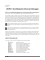
LEVEL7 Non-Maskable Interrupt Debugger
LEVEL7, the non-maskable interrupt debugger, is a utility to examine the status of a locked-up system.
This can be very useful when debugging interrupt level routines or other functions which may appear to
lock the system. You can also set LEVEL7 to trigger on the standard exception vectors.
To use LEVEL7 to debug a “locked” system, you need to emulate a power fail condition by using either
a switch wired to the UPS port on the CPU board, or via front panel control on those systems supporting
that function. Therefore, you can use LEVEL7 to diagnose system lockups only on CPU boards which
have a UPS port, such as the AM-185-50, AM-4000, Eagle 550, and AM-6000, or on CPU boards which
have configurable front panel control of LEVEL7, such as the Eagle 450 and AM-6060. Information on
constructing the necessary switch for invoking LEVEL7, or information on configuring the CPU board
for front panel control of LEVEL7 is at the end of this document.
Using the LEVEL7 debugger preempts any power fail operations usually performed within the
AMOS monitor; therefore it should only be installed during debugging, not as a normal system
utility.
If your CPU does not have a UPS port or front panel LEVEL7 control, you can still use LEVEL7
to debug any condition which causes one of the normal exception vectors by using the /E or /T
switch, described below.
LEVEL7 is user-extensible via custom overlays, several of which are included. Further information on
programming these overlays is covered later in this document. If you develop your own overlay, and
want it to be included, please submit it with source and instructions to Alpha Microsystems. The overlay
will become property of Alpha Microsystems if included with LEVEL7; no compensation will be given
to the author.
LEVEL7 RELEASE FILES
As of release 1.0(116), the LEVEL7 debugger consists of the following files:
LEVEL7.SYS
GOL7.LIT
JCB.L7O
TCB.L7O
DDB.L7O
MAP.L7O
SMEM.L7O
DISASM.L7O
IDENT.L7O
EXAMPL.M68
L7OSYM.M68
Rev. B02
Main debugger module
Program to execute the debugger manually
Overlay to display job control blocks
Overlay to display terminal control blocks
Overlay to display dataset driver blocks
Overlay to display memory modules
Overlay to display shared memory area
Overlay to disassemble 680x0 instructions
Overlay to identify memory areas
Example overlay source file
Symbol file for developing new overlays
Page 2
LEVEL7 Non-Maskable Interrupt Debugger
INSTALLING LEVEL7
Place the files LEVEL7.SYS and GOL7.LIT in DSK0:[1,4] and all overlays (*.L7O) in DSK0:[7,0]. The
source files are needed only if you plan on creating your own overlays. You may install them anywhere;
DSK0:[7,7] is normally a good choice.
In your system initialization file (always edit a copy of the file, not the original), locate the SYSTEM
statements. Before the final SYSTEM statement, add this statement:
SYSTEM LEVEL7.SYS/N{/E}{/T}{/P} {overlay} {overlay} {. . .}
/E is an optional switch which causes the normal exception vectors to be trapped. This means LEVEL7
will be invoked for such things as illegal instructions or address errors.
/T is the same as /E, except that it allows you to toggle exception vector trapping by using the GOL7
command (see below). This lets you enable and disable exception trapping without rebooting your
computer.
You can use /P with /E or /T to ignore privilege violations. These errors often occur due to differences in
newer CPUs from the original Motorola 68000. Normally AMOS handles them for you; however, the /E
or /T switch can cause LEVEL7 to trigger on them.
Each overlay is an optional overlay file to load. Though they are not required, most are very useful. For
example, the overlay JCB.L7O is available for displaying job control block information.
The proper SYSTEM statement, with all of the currently available overlays and exception trapping
enabled, but privilege violations ignored, would look like this:
SYSTEM LEVEL7.SYS/N/E/P JCB TCB DDB MAP SMEM DISASM IDENT
Once you reboot your system, the debugger should be ready. LEVEL7 will be invoked in any of three
circumstances:
• If you press a button wired to the CPU UPS port, simulating a power fail condition.
• If you use /E or /T, on any of the normal exception vectors.
• If you didn’t use /T, when you enter the GOL7 command. This is handy for verifying the
debugger is properly installed.
If you use the /T switch, GOL7 does not enter LEVEL7. Instead, it toggles exception trapping. Exception
trapping is off when the system boots: the first use of GOL7 turns it on, the next turns it off, etc.
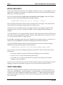
LEVEL7 MAIN MENU
The LEVEL7 debugger operates at interrupt level with interrupts locked. No other processing occurs
while you are in the debugger. When the debugger is activated through a power fail interrupt, processor
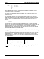
exception, or the GOL7 command, the diagnostic panel displays a “7” and the following menu appears
on the terminal attached to CPU port #0. The activated by line appears only when LEVEL7 is entered
due to an exception:
Rev. B02
LEVEL7 Non-Maskable Interrupt Debugger
Page 3
LEVEL7 outputs at 19200 baud only. The peripheral attached to CPU port #0 must be set to 19200
baud or the debugger’s output will be unreadable.
***** Level 7 Interrupt Debugger *****
(activated by XXXXXX exception)
------------------------------------------------------------Primary Functions:
1) Exit Level 7 Handler
2) Show Stacked Registers
3) Examine/Modify Location 4) Show System Comm. Area
5) Display memory block
Extended Functions:
6) Display JCB information
7) Display TCB information
8) Display DDB information
9) Display memory modules
10) Display shared memory (SMEM)
11) 680x0 Disassembler
12) Identify an address
The primary functions listed are functions supported within LEVEL7 itself. Extended functions are the
overlays you have specified. In the example, a number of overlays have been loaded. Your extended
functions list may be different.
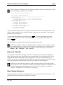
To return to the Main Menu from any function, press CTRL /C. To leave the debugger and release
operation of the system, select option 1 on the Main Menu. You may redisplay the Main Menu by
pressing RETURN .
The following sections describe each of the functions available on the menu.
Various areas within the primary and extended functions will request a memory address. You can
use an absolute address, or reference a stacked register or an offset from one. All addresses and
offsets must be entered in hexadecimal. For example, all of the following are valid responses:
1A4B20 @A5 1290(A0) @D5 4A(D3)
Exit Level 7 Handler
This option leaves the LEVEL7 debugger. If LEVEL7 was invoked via a button on the UPS port the
system will return to the state it was in before you pressed the button. If it was invoked via GOL7, the
system should continue running and the job executing GOL7 will return to the AMOS prompt. If
LEVEL7 was invoked via a trapped exception, AMOS will be given the exception for normal processing.
Usually this means the job generating the exception will be aborted in the usual manner.
Note there are cases where the system may crash or various interfaces will stop working when
you exit LEVEL7. This is caused by having the system interrupt locked for an extended period of
time while interrupt-generating hardware is still active. This is especially true of Ethernet
interfaces. Though this is a rare occurrence, it can happen.
Show Stacked Registers
This option displays the contents of all registers as they were the moment LEVEL7 was entered. It also
displays the stack frame which caused LEVEL7 to be entered.
Rev. B02
Page 4
LEVEL7 Non-Maskable Interrupt Debugger
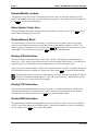
Examine/Modify Location
This option lets you read or write a single memory location. After you select this option you will be
asked for the address, then for the size of the read/write to perform. This sequence will repeat endlessly.
Press CTRL /C to return to the Main Menu.
Show System Comm. Area
This option displays the system communication area at 0x400, one page at a time. Press
want to abort the listing prior to the end.
CTRL
/C if you
Display Memory Block
This option displays a selected area of memory. Several formats are available; when you select this
option you are asked for the format you want, then for the starting address to display. LEVEL7 will
display one page of information. You may then press RETURN to display the next sequential area or enter
a new address. This continues until you press CTRL /C to return to the Main Menu.
Display JCB Information
This option displays information about a selected job. LEVEL7 asks what job selection method you
want to use. The by number selection allows you to select by position in the job table. This is handy for
scanning job by job. The RunQ List selection displays the active jobs in run queue order.
After you pick the selection method, LEVEL7 asks what job you want to display. It displays the selected
job information and asks for another job. When you’re done, press CTRL /C to return to the Main Menu.
The displayed registers are for the job when running. If this job is the one referenced by JOBCUR,
then they will match the stacked registers. If this job is not referenced by JOBCUR, the registers
are from the user’s system stack area in memory.
Display TCB Information
This option displays information about a selected terminal. As with the JCB function, LEVEL7 asks
what selection method you want, then for the terminal. It displays the information for the selected
terminal, then lets you specify another. Press CTRL /C to return to the Main Menu.
Display DDB Information
This option displays information about dataset driver blocks which are used to access devices and files.
LEVEL7 asks for the address of the DDB to display. It displays the address you select as a DDB and
asks for another. Press CTRL /C to exit to the Main Menu.
Rev. B02
LEVEL7 Non-Maskable Interrupt Debugger
Page 5
Display Memory Modules
This option lets you display memory module information in system memory, user memory, or starting
from a selected address. LEVEL7 asks for the area you want to display. It then lists memory modules
one page at a time. If any of the stacked address registers contain a value within the listed module they
are displayed to the right of the screen. To exit prior to the end of the modules, press CTRL /C.
Display Shared Memory (SMEM)
This option displays the shared memory area set up by the SMEM command. If any of the stacked
address registers contain a value within the listed area they are displayed to the right. If any JCBs are
located within the listed area the job name is displayed.
680x0 Disassembler
This option lets you see a disassembled listing of code anywhere in memory. You select the starting
disassembly address. By default, it begins disassembling 20 hex bytes prior to the stack program
counter. A page of disassembled instructions will then be displayed. When you’re done, press CTRL /C
to return to the Main Menu. You can use these keys with this function:
A
D
SPACE
RETURN
Display stacked address registers
Display stacked data registers
Display another page
Display another line
Identify an Address
This option lets you enter an address and attempts to identify its location. It can identify I/O, nonexistent memory, modules, and other areas. This function will be enhanced as methods are perfected to
identify more hard-to-map areas within AMOS.
CREATING LEVEL7 OVERLAYS
To allow examination of data not originally anticipated in the creation of LEVEL7, you may write your
own overlays which LEVEL7 can load and add to its menu when the system boots. Remember, these
routines will run at interrupt level and have no AMOS functions available to them.
Rev. B02
Page 6
LEVEL7 Non-Maskable Interrupt Debugger
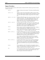
Support Functions
We provide the following macros, which interface to internal LEVEL7 routines to provide for I/O and
common conversions:
CHROUT
Outputs a character to the terminal. The character should be placed
in D1.
STROUT adr
Outputs a string to the terminal. adr is the address register or label
where the string is located. STROUT behaves like the TTYL monitor
call; it does NOT handle immediate strings like the TYPE monitor
call.
HEXOUT nib,{mem}
By default, HEXOUT outputs a hex value to the terminal. The value
should be placed in D1. The required nib argument can be a data
register or immediate value specifying the number of nibbles to
output. Specifying a value for the optional mem argument causes
HEXOUT to send its output to a buffer indexed by A2.
DECOUT {memory}
By default, DECOUT outputs a decimal value to the terminal. The
value should be placed in D1. The {memory} argument is optional.
Specifying a value for the optional memory argument causes
DECOUT to send its output to a buffer indexed by A2.
CHRIN
Reads a character from the keyboard and returns it in D1. If there is
a serial communications error, CHRIN returns NE status.
STRIN
Reads a string from the keyboard. The entered string is indexed with
A2 upon return. If ^C is entered, STRIN returns NE status.
HEXIN {memory}
By default, HEXIN inputs a hex value from the keyboard and returns
it in D1. If a ^C is entered or the input is invalid, HEXIN returns NE
status. Specifying a value for the optional memory argument causes
HEXIN to process input from a buffer indexed by A2.
A nice feature provided by HEXIN involves the use of stacked
registers. If a user specifies a data or address register in the input,
HEXIN automatically and transparently handles it.
DECIN {memory}
By default, DECIN inputs a decimal value from the keyboard and
returns it in D1. If a ^C is entered or the input is invalid, DECIN
returns NE status. Specifying a value for the optional memory
argument causes DECIN to process input from a buffer indexed by
A2.
UNPAK
Converts RAD50 to ASCII. The RAD50 value should be indexed
with A1. A2 should reference a buffer for the ASCII conversion. The
UNPAK call operates like the UNPACK monitor call.
PAK
Converts ASCII to RAD50. The ASCII value should be indexed with
A2. A1 should reference a buffer for the RAD50 conversion. The
PAK call operates like the PACK monitor call.
Rev. B02
LEVEL7 Non-Maskable Interrupt Debugger
Page 7
EXAMPL.M68 Example Overlay
LEVEL7 includes source code for an example overlay file. By examining this and using it as a template
you will be able to understand the requirements of LEVEL7 overlays:
; EXAMPL - Example LEVEL7 overlay source - does nothing special
VMAJOR
VMINOR
VSUB
VEDIT
VWHO
SEARCH
SEARCH
COPY
OBJNAM
SYS
SYSSYM
L7OSYM
.L7O
RADIX
16
=
=
=
=
=
1
0
0
100.
0
; overlay MUST have the label BASE: at the base of the module!
BASE:
PHDR
-1,0,0
; Program version area
LWORD
NAME-BASE
; Offset to menu item text
LWORD
INIT-BASE
; Offset to initialization code
LWORD
CODE-BASE
; Offset to functional code
.=L7HSIZ
; skip the rest of the overlay header
; String which will appear as overlays menu entry
NAME:
ASCIZ
"Example extended function"
EVEN
; Initialization code (not really much to do right now)
; Called at boot time with boot jobs context, USE AMOS CALLS
INIT:
TYPECR <Example overlay loaded and ready>
LCC
#PS.Z
; successful return
RTN
; Actual code called by LEVEL7, A0 points to stacked registers upon entry.
; Interrupts locked, no job context, DON'T USE AMOS CALLS
CODE:
STROUT HELLO1
; output first part of welcome msg
MOV
A0,D1
; get address of stacked registers
HEXOUT #8.
; output all 8 nibbles
STROUT HELLO2
; finish welcome message
10$:
STROUT PROMPT
; output prompt
CHRIN
; get a keystroke
CMPB
D1,#'Q
; 'Q' hit?
BEQ
20$
;
yes - leave
CMPB
D1,#'q
; 'q' hit?
BNE
10$
;
no - prompt user again
20$:
STROUT BYBY
; say bye
RTN
; back to main menu
; Messages
HELLO1: ASCII
BYTE
ASCII
BYTE
ASCIZ
EVEN
"Hello, welcome to the example overlay"
^H0D,^H0A
"function. The stacked registers are"
^H0D,^H0A
"at "
HELLO2: ASCII
BYTE
EVEN
". Press Q to leave here."
^H0D,^H0A,0
PROMPT: BYTE
ASCIZ
EVEN
^H0D,^H0A
"Press 'Q': "
Rev. B02
Page 8
LEVEL7 Non-Maskable Interrupt Debugger
BYBY:
BYTE
ASCIZ
BYTE
EVEN
^H0D,^H0A
"Goodbye, returning to main menu..."
^H0D,^H0A,0
END
Macros and header offsets for LEVEL7 overlays are contained in the file L7OSYM.M68, which is
COPYed into the program as it is assembled.
The extension of the object module should be .L7O, which is set by the OBJNAM statement in the
example code above.
The overlay header consists of a program header PHDR prefixed by the label BASE:, offsets from
BASE: to the title string, initialization code, and functional code. There are several other header items
filled in by LEVEL7 itself which you must skip over before your code begins. This is done by the
statement:
.=L7HSIZ.
The initialization code is called once when the system boots and LEVEL7 is loaded in the SYSTEM
statements. This is the only place in the code where there is a job context and AMOS monitor calls. The
initialization code can store a copy of initial system areas, perform some setup, or do nothing. If
initialization is successful, you must return EQ status. Upon failure, you should print some appropriate
message (using the AMOS I/O calls) and return NE status.
The functional code is called whenever the user selects your entry on the main LEVEL7 menu.
Interrupts are locked and no AMOS calls may be performed at that time. I/O should be performed using
the LEVEL7 support macros only.
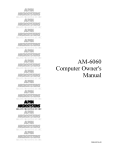
Register A0 points to the base of the stacked registers. Above these registers is the interrupt stack frame
which invoked LEVEL7. The format of the stack frame will vary by processor as well as by entry
method (UPS port versus exception). In any case, the base of the stack frame will always be the same.
The area looks like this:
Location
↑
higher addresses
↑
@A0 points here →
Contents
frame type
return address
processor status
A0 through A6
D0 through D7
Size
word
longword
word
longwords
longwords
Make sure you provide a way to return to the Main Menu from anywhere you accept input, such as with
a CTRL /C. To return to the Main Menu, simply clean up any stack operations you have done and execute
a RTN.
Rev. B02
LEVEL7 Non-Maskable Interrupt Debugger
Page 9
UPS PORT WIRING OR FRONT PANEL LEVEL7 CONTROL
Several Alpha Microsystems computer systems include an external UPS port which can be used to
generate a power fail condition which will allow LEVEL7 to interrogate “locked” systems. These
systems include the following models:
AM-3000 (50 MHz version)
AM-4000 (AM-190 board)
Eagle 450
Eagle 550
AM-6000
You will need the following parts to generate LEVEL7 interrupts (power fails) through the external UPS
port:
•
•
•
•
1 SPST momentary push-button
1 female DB-9 connector
5 feet or less 24-gauge, twisted-pair wire
1 100 ohm resistor (for AM-190 rev B or earlier ONLY)
Unless you are using an AM-190 revision B or earlier CPU board, connect the push-button between pins
2 and 9 of the DB-9 connector. This is for all later model AM-190s, and all other systems listed.
If you are using an AM-190 revision B or earlier CPU board, connect the push-button to pin 2 of the DB9 connector, and one end of the 100 ohm resistor to pin 9. Connect the remaining side of the resistor and
push-button together so they are in series.
Some Alpha Microsystems computer systems have the capability of generating a power fail condition
through the TURBO switch on the front panel of the computer system. These systems include the
following models:
Eagle 450
AM-6060
The Eagle 450 (AM-138 CPU board) can be configured to enable the TURBO switch to force a power
fail condition for diagnostic purposes, thereby enabling LEVEL7 analysis. To configure the AM-138
board for this function, simply move the shorting block near the UPS external 9 pin connector J1 from
the UPS position to the FPSEL position.
The AM-6060 can also be configured to utilize the TURBO switch to trigger power fail, even though this
system has no external UPS connector. To configure this system to enable the TURBO switch to force a
power fail condition, install jumper JP5 on the AM-301-10 daughter board plugged into the main AM6060 CPU board. The position of this jumper is shown in the AM-6060 Service Manual furnished with
the system. Remember to remove the shorting block after completing the LEVEL7 analysis.
The TURBO switch on most Eagle 450 and AM-6060 systems is a latching toggle switch. Hence
you must depress it twice to set LEVEL7. If it is not a latching toggle switch, then you will only
need to depress the switch once.
Rev. B02