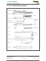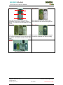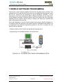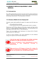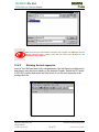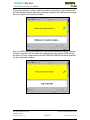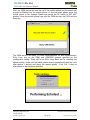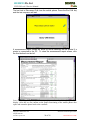
1
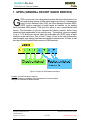
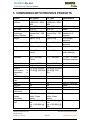
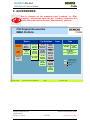
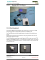
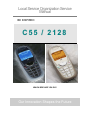
Local Service Organization Service
Manual
BE INSPIRED
C55 / 2128
WHICH SIDE ARE YOU ON?
Our Innovation Shapes the Future
SIEMENS Pte Ltd
C55/2128 Level 2 Service Manual
TABLE OF CONTENTS
1
GPRS (GENERAL PACKET RADIO SERVICE).............................................. 1
2
K-JAVA APPLICATION ...................................................................................... 2
3
KEY FEATURES.................................................................................................... 3
4
OTHER FEATURES.............................................................................................. 4
5
COMPARISON WITH PREVIOUS PRODUCTS.............................................. 5
6
ACCESSORIES ...................................................................................................... 6
6.1
7
ACCESSORIES PART NUMBER....................................................................7
UNIT DESCRIPTION L55 TUNA........................................................................ 8
7.1
7.2
7.3
7.4
ASSEMBLY CONCEPT FOR THE CUSTOMER .................................................8
C55 / 2128 MECHANICAL DIAGRAM ...........................................................9
PCB TOP-SIDE .......................................................................................10
PCB BOTTOM-SIDE .................................................................................10
8
DISASSEMBLY OF C55/2128 ............................................................................ 11
9
REASSEMBLY OF C55/2128 ............................................................................. 13
10
SPARE PARTS & PART NUMBERS ................................................................ 14
11
MOBILE SOFTWARE PROGRAMMING....................................................... 15
11.1
11.2
12
MOBILE SOFTWARE UPDATING.......................................................16
FLOW CHART FOR S/W UPGRADING .........................................................17
SIEMENS SERVICE EQUIPMENT USER MANUAL ................................... 18
12.1 INTRODUCTION .......................................................................................18
12.2 SIEMENS MOBILE SERVICE EQUIPMENT ....................................................18
12.2.1 R&S CMD55 Test Station .................................................................19
12.2.2 R&S CTS55 Test Station ..................................................................19
12.2.3 Wavetek 4201S Test Station.............................................................20
12.3 OTHER EQUIPMENT ................................................................................20
12.4 SOFTWARE INSTALLATION .......................................................................21
12.4.1 Configuring the test software ............................................................22
12.4.2 Running the test sequence ...............................................................23
Copyright © Siemens Pte. Ltd.
All rights reserved
ICM MP CCQ ASP/ASC
Siemenes Techincal Support Center
Contents Page 1
Internal Service Use Only
SIEMENS Pte Ltd
C55/2128 Level 2 Service Manual
1 GPRS (GENERAL PACKET RADIO SERVICE)
G
PRS is a new non-voice value added services that allows information to be
sent and received across a GSM mobile telephone network. It supplements
today’s Circuit Switched Data (CSD) and Short Message Services (SMS).
GPRS involves overlaying a packet based air interface on the existing
circuit switched GSM network. This gives the option to use a packet-based data
service. The information is split into separated but related “packets” before being
transmitted and reassembled at the receiving end. Theoretically, maximum speeds
of up to 171.2 kilobits per second (kbps) are achievable with GPRS using all eight
timeslots at the same time. This is about 3 times as fast as the data transmission
speed possible over today’s fixed telecommunications networks and 10 times as fast
as current Circuit Switched Data services on GSM networks.
Figure1. Example of GPRS data transmission
Example: Cell with 1 Frequency channel:
1 physical channel for signalling, 4 physical channels for Circuit switched
and 3 physical channels for Packet switched
Copyright © Siemens Pte. Ltd.
All rights reserved
ICM MP CCQ ASP/ASC
Siemenes Techincal Support Center
1 of 28
Internal Service Use Only
SIEMENS Pte Ltd
C55/2128 Level 2 Service Manual
2 K-JAVA APPLICATION
Java-based
game system
Java Application Manager
(JAM)
RAM for Java applications
yes
Application launcher and download manager.
Supports HTTP-based OTA download of applications
over GPRS and CSD.
Available RAM for Java applications (ie. program code
and data) during application runtime:
yes
Minimum: 100 Kbyte
(Has to be taken as working assumption for application
development.)
Goal: 145 Kbyte as SL45i (not committed)
MIDP 1.0, CLDC 1.0
'OEM extensions'
HTTP API over GPRS
As SL45i, including performance optimizations from
SL45i-Infusio.
yes
Proprietary API extensions as SL45i. Including
'Siemens Game API'
yes
SL45i: only over CSD
yes
Copyright © Siemens Pte. Ltd.
All rights reserved
ICM MP CCQ ASP/ASC
Siemenes Techincal Support Center
2 of 28
Internal Service Use Only
SIEMENS Pte Ltd
C55/2128 Level 2 Service Manual
3 KEY FEATURES
General:
Battery:
Stand-by
Time:
Talk Time:
SIM Card:
Speech
Coder:
Display:
Keypad:
Acoustics:
• Hands free
• Flash file system
• New sound concept with polyphonic ringing tones / social
noises
• Kjava (identical to K45-Manta)
• LiIon Battery Pack 700 mAh
• Power Input: 1.8 A (0.6 ms) / 0.2 A (4 ms)
• Cut-off Threshold 3.2 V
• approx. 250 h measured at BSPAMFRMS = 9; number of
neighbouring cells = 0
• Best case approx. 5 hours (lowest output level with DTX)
• Worst case approx. 2.5 hours (highest output level without
DTX)
• Conditions for DTX: 40% user talk time
• Small (=”Plug In“) 1.8 V or 3 V-SIM card (Phase II).
• To insert the SIM the battery pack must be removed.
• The SIM reader coding will be realized by lower case.
• Full Rate, Enhanced Full Rate, Adaptive Multi Rate and
Half Rate speech coders are available as standard.
• Type: Full Graphic
• Resolution: 101 X 64 Pixel
• Illumination: Amber
• 12-digit block (0-9, #, *), small letters
• two function keys (SEND, END)
• ON/OFF key combined with the END key; the symbol ¢ (I
inside O) is used as a symbol for ON/OFF.
• 4 way navigation key as centered rocker type (up&down / 2
softkeys on left & right position)
• amber as illumination colour
• orientation at the housing in the area between keys “5“ and
“8”
• comfortable earpiece with optimal acoustics
• unidirectional microphone (similar to SL45 with modified
rubber gasket)
• loud signal emitter (soundringer) (>100dB(A) SPL @5cm,
'Hongkong-Spec.')
• different call melodies (for the amount see SW product
description). Realized with DSP firmware sound solution. All
melodies with increasing volume because of the danger of
acoustic shock. Additional measures to protect from
acoustic shock, see SW product description.
Copyright © Siemens Pte. Ltd.
All rights reserved
ICM MP CCQ ASP/ASC
Siemenes Techincal Support Center
3 of 28
Internal Service Use Only
SIEMENS Pte Ltd
C55/2128 Level 2 Service Manual
• handsfree mode
• different selectable volume levels for handsfree, handset
and ringer mode (for the amount see SW product
description)
4 OTHER FEATURES
•
•
•
•
•
•
•
•
•
•
•
•
•
•
•
•
•
•
•
Games (Java Based)
Voice command/dialing
Integrated handsfree
Calling Images: Download a photo of your friend and link it to his phone book
entry
Greetings (Reminder of important dates)
Get in touch (Conference Call) & SMS to group
Text modules (SMS)
Diary (appointments, notes)
Flexible Memory
PIN protected screensaver & notes
Various animations (menu, welcome)
Silent Alert
Various user profiles
Intelligent Typing (T9) + Libraries
Mobile Internet Access (WAP 1.2.1)
Built in data & fax modem @ 9.6 kbps
Moon phase screensaver (2128 only)
VOIP Predial
Integrated sound concept (polyphonic melodies with up to 16 voices) for:
- MMI
- Ringer melodies
- Recordable sounds
Copyright © Siemens Pte. Ltd.
All rights reserved
ICM MP CCQ ASP/ASC
Siemenes Techincal Support Center
4 of 28
Internal Service Use Only
SIEMENS Pte Ltd
C55/2128 Level 2 Service Manual
5 COMPARISON WITH PREVIOUS PRODUCTS
Feature
Supported
Systems
Stand-by Time
Talk Time
Battery
Technology
Battery Capacity
Weight
K45 Flipper
Dual Band
E-GSM 900 / GSM
1800
Up to 200 h
Up to 5 h
Ni-MH Battery Pack
Nominal Cap. : 550
mAh
Approx. 106 g
L55 Tuna
Dual Band
E-GSM 900 / GSM
1800
Up to 250 h
Up to 5 h
Li-Ion Battery Pack
Nominal Cap.: 750
mAh
Approx. 84 g
Volume
Approx. 82 cm3
Approx. 69 cm3
Length
108,9 mm (Panther) 100,9 mm
Width
42.0 ... 46.0 mm
(Panth)
41.0 ... 44.0 mm
1.0 mm … 2.0 mm
width reduction
Thickness
19.0 ... 23.0 mm
(Panth)
17.9 ... 20.8 mm
1.1 mm … 2.2 mm
thickness reduction
SIM
Antenna
Antenna
Performance
in
comparison
to
S35:
Half Rate
Enhanced
Full
Rate
AMR
Fax/Data
GPRS
Keypad
Illumination
Display /
Display
Illumination
Ringer
volume
level
Plug-In 1.8V/3V
Integrated
-0,5 dB @ 900 MHz
-0,3 dB @ 1800 MHz
Plug-In 1.8V/3V
Same
Integrated
Same
-0,8 dB @ 900 MHz
-0,5 dB @ 1800
MHz
Yes
Yes
Yes
Yes
Same
Same
No
Yes
No
Yes (amber)
Tbc
Yes
Yes
Yes (amber)
New in C-segment
Same
New in C-segment
Same
FSTN full dot
matrix, 5 lines
graphic
Min. 100 dB(A) @
5cm
Typ. >103 dB(A) @
5cm
Same
FSTN full dot
matrix, 5 lines
graphic
Min. 100 dB(A) @ Same
5cm
Typ. >103 dB(A) @
5cm
Copyright © Siemens Pte. Ltd.
All rights reserved
ICM MP CCQ ASP/ASC
Improvement
Same
+20% stand-by time
Same
Li-Ion first time as
standard in Csegment
-20% weight
reduction
-16% volume
reduction
8 mm shortening
Siemenes Techincal Support Center
5 of 28
Internal Service Use Only
SIEMENS Pte Ltd
C55/2128 Level 2 Service Manual
6 ACCESSORIES
Due to changes on the connector from “Lumberg” to “Slim
Lumberg”, accessories using the old “Lumberg” connector will
not be able to be used on the new “Slim Lumberg” platform.
C55 Original Accessories
EMEA Portfolio
Basics
Basics
Car
Car Solutions
Solutions
Carry
Carry Set
Set
FCS-500
FCS-500
Li-Ion
Li-Ion
Battery
Battery
EBA-510
EBA-510
Desk
Desk Top
Top
Charger
Charger
EDC-510
EDC-510
Car
Car Kit
Kit
Prof.
Prof. Voice
Voice
HKV-500
HKV-500
Mobile
Mobile
Holder
Holder
HMH-500
HMH-500
CLIPit
CLIPit
Covers
Covers
Headset
Headset
PTT
PTT
HHS-510
HHS-510
Travel
Travel
Charger
Charger
ETC-500
ETC-500
ETC-510
ETC-510
Car
Car Kit
Kit
Comfort
Comfort
HKC-500
HKC-500
Mobile
Mobile
Holder
Holder
Antenna
Antenna
HMH-510
HMH-510
Car
Car Charger
Charger
ECC-500
ECC-500
Car
Car Kit
Kit
Portable
Portable
HKP-500
HKP-500
Car
Car Kit
Kit
Upgrade
Upgrade
HKO-500
HKO-500
Basic
Basic
Car
Car Pack
Pack
HKB-500
HKB-500
Car
Car Kit
Kit
Upgrade
Upgrade
HKO510
HKO510
Carrying
Carrying
Cases
Cases
Data
Data
Innov.
Innov.
Data
Data Cable
Cable
DCA-500
DCA-500
Data
Data Cable
Cable
USB
USB
DCA-510
DCA-510
SyncStation
SyncStation
DSC-500
DSC-500
(Desk
(Desk Top
Top Stand,
Stand, Y-Adapter,
Y-Adapter,
Data
Data Cable)
Cable)
compatible to L55
and future products
C55 and S55 only
C55 only
Car
Car
Handset
Handset
HKO-550
HKO-550
ICM MP CCQ SF
www.my-siemens.com/customercare
Page 1
Copyright © Siemens Pte. Ltd.
All rights reserved
ICM MP CCQ ASP/ASC
© Siemens, 2002
Siemenes Techincal Support Center
6 of 28
Internal Service Use Only
SIEMENS Pte Ltd
C55/2128 Level 2 Service Manual
6.1 Accessories Part Number
Accessories
L36104-F3090-X903 Handsfree Loudspeaker S45/ME45/C45/M45/C55/S55
L36146-A2053-D
Con.Cable Battery Install. Comfort GPS/rat C35/C35
L36254-Z6-C95
Handsfree Microphone aktiv S45/ME45/C45/M45/C55/S5
L36880-N4501-A135 HKO-520 Push-To-Talk-Key
L36880-S4501-A300 E-Box Carkit Voice S45/ME45/C45/M45/C55/S55 german
L36880-S4501-A301 E-Box Carkit Voice S45/ME45/C45/M45/C55/S55 englis
L36880-S4501-A302 E-Box Carkit Voice S45/ME45/C45/M45/C55/S55 french
Copyright © Siemens Pte. Ltd.
All rights reserved
ICM MP CCQ ASP/ASC
Siemenes Techincal Support Center
7 of 28
Internal Service Use Only
SIEMENS Pte Ltd
C55/2128 Level 2 Service Manual
7 UNIT DESCRIPTION L55 TUNA
The L55 Tuna is designed as a single-pcb phone with exchangeable covers and
exchangeable keypad. The upper- and lower-cover are designed as two-coloured
parts, which is realized in 2-shot-moulding technology.
7.1 Assembly Concept for the Customer
Chassis
exchangeable
Rear-Cover
exchangeable
Front-Cover
battery
exchangeable
keypad
SIM-Card
The C55 is the first Siemens Mobile phone that enables the customer to freely
customize the outlook of their phone via the means of exchangeable Front/Rear
covers as well as keypad.
Copyright © Siemens Pte. Ltd.
All rights reserved
ICM MP CCQ ASP/ASC
Siemenes Techincal Support Center
8 of 28
Internal Service Use Only
SIEMENS Pte Ltd
C55/2128 Level 2 Service Manual
7.2 C55 / 2128 Mechanical Diagram
D isp la y-W in d o w
U p p e r-C a se
K e yp a d
S A R -F ra m e
S A R -A b so rb e r
(o p tion a l)
E S D -F ra m e
S p e a ke r-G a ske t
LCD
L ig h tg u id e
S p e a ke r
M e ta ld o m e -F oil
PCB
V ib ra -m o to r
A n te n na
M icro p h o n e
M o u n tin g -F ra m e
B a tte ry
L o w e r-C a se
Copyright © Siemens Pte. Ltd.
All rights reserved
ICM MP CCQ ASP/ASC
Siemenes Techincal Support Center
9 of 28
Internal Service Use Only
SIEMENS Pte Ltd
C55/2128 Level 2 Service Manual
7.3 PCB top-side
7.4 PCB bottom-side
The C55/2128 assembly concept differs from the previous models (P35 & K45
series) slightly. The C55/2128 is no longer employing the concept of “No
Screws”. Instead of the previous upper & lower mounting frame to hold the PCB
and the housing together, the C55/2128 uses six screws to hold the light guide,
PCB and the mounting frame together.
As seen from the mechanical diagram, the C55/2128 also uses two other
different techniques from the previous models (P35 & K45 series). (1) The use of
a light guide on the front panel to disperse the light evenly throughout the keypad
& display area. (2) The use of a metal dome foil as keypad contact as opposed to
the carbon/metallic contact keypads used in the P35 & K45 series.
Copyright © Siemens Pte. Ltd.
All rights reserved
ICM MP CCQ ASP/ASC
Siemenes Techincal Support Center
10 of 28
Internal Service Use Only
SIEMENS Pte Ltd
C55/2128 Level 2 Service Manual
8 DISASSEMBLY OF C55/2128
Step 2
Step 1
Front view of the C55/2128
Back view of the C55/2128
Step 3
Step 4
Remove the battery cover by pushing it
upwards as indicated by the arrow.
The C55/2128 comes with a hinge on the top
part of the phone for customers to hang their
accessories.
Step 5
Step 6
With the battery cover removed, proceed to
remove the battery by releasing the catch on
the side.
With the battery removed, you would then be
able to see the SIM card, which is held down
by a metallic catch.
Step 7
Step 8
Once the catch has been removed, the SIM
card would pop up from the holder
automatically.
Proceed to remove the front cover by pushing it
up lightly.
Copyright © Siemens Pte. Ltd.
All rights reserved
ICM MP CCQ ASP/ASC
Siemenes Techincal Support Center
11 of 28
Internal Service Use Only
SIEMENS Pte Ltd
C55/2128 Level 2 Service Manual
Step 9
Step 10
Once the front cover has been removed,
proceed to remove the 6 screws on the front
with a “T6” screw driver; as indicated by the red
circles.
Once the screws has been removed, you
would be able to see the internal single PCB.
Step 11
Step 12
Once the screws has been removed, the PCB
can also be seperated from the back casingof
the phone. The antenna is built-in on the back
case.
As it can be seen from the photo, the keypad
can also be separated from the front casing.
Step 13
Fully disassembled C55
Copyright © Siemens Pte. Ltd.
All rights reserved
ICM MP CCQ ASP/ASC
Siemenes Techincal Support Center
12 of 28
Internal Service Use Only
SIEMENS Pte Ltd
C55/2128 Level 2 Service Manual
9 REASSEMBLY OF C55/2128
For the reassembly of the C55/2128, simply reverse the disassembly
procedures from Step 13 to Step 1. However there are some things to note
on the reassembly of the phone.
During the installation of the SIM card, ensure that the SIM card is properly
locked in. If not, it would result in card error, as the SIM card will not be properly
held in place.
Ensure that the SIM card is fully inserted and that the metallic lock is pulled
down.
During the installation of the battery, ensure that the hinges are properly in place.
Otherwise the battery will not be able to fit into the phone properly.
Ensure that the hinges are properly fitted before fixing in the battery.
Copyright © Siemens Pte. Ltd.
All rights reserved
ICM MP CCQ ASP/ASC
Siemenes Techincal Support Center
13 of 28
Internal Service Use Only
SIEMENS Pte Ltd
C55/2128 Level 2 Service Manual
10 SPARE PARTS & PART NUMBERS
Level 1
L36158-A102-B600 Keypad C55/C56
Level 2.5
L36197-F5005-F782
L36334-Z93-C272
L36334-Z97-C160
L36840-L2055-D670
L36840-L2056-D670
Display LED blue MT50/M50/M46/C55
Antenna Connector C35/C35i/S35i/M35i/SL45/ S45/ME4
Battery Connector S45/ME45/C55/S55
Display LED Amber S35i/S45/ME45/C45/M50/C55/C56
Keyboard LED Amber S35i/S45/ME45/C45/S46/M50/MT50/
Level 2.5E
L36120-F4223-H
Resistor Temp_Resistor
L36145-F102-Y8
Quartz EGold/Logic (B1 lay.)
L36145-G100-Y96 Z850 Filter 1LO_VCO
L36145-K260-Y41 Z851 Filter Filter_BALUN
L36820-C6047-D670 Diode / Transistor Tran._Switch
L36820-L6105-D670 D800 Digital Integrated Circuit (IC) Transceiver I
L36830-C1097-D670 Diode / Transistor
L36840-C4049-D670 Diode / Transistor Tran._VCXO_Ampl.
L36840-D5049-D670 Diode / Transistor Feedback_Diode
L36840-D61-D670 Diode / Transistor Capa_Diode
L36851-Z2002-A59 Z900 Filter Power_Amplifier
L36851-Z9105-Z981 Diode / Transistor
Copyright © Siemens Pte. Ltd.
All rights reserved
ICM MP CCQ ASP/ASC
Siemenes Techincal Support Center
14 of 28
Internal Service Use Only
SIEMENS Pte Ltd
C55/2128 Level 2 Service Manual
11 MOBILE SOFTWARE PROGRAMMING
The common mobile software available is divided into language groups. However, this
software does not contain the specific settings, such as ringing tones, greeting text, short
dial list etc., required by the operator(s) or service provider(s). Therefore, it is not
uncommon to have some menu item(s) differ in different variants or are not visible at all.
These settings are stored in different memory area of the mobile and will be activated
depending on the customer specific model or variant of the phone by a separate test
step during the production process.
Due to this separation of common mobile software and customer specific initialization, it
is possible to fulfill the demands of the market requiring customization and flexibility. As
a consequence the software programming process in the LSO is divided into two
different steps as followed:
- Software update to actual version and appropriate language group
- Programming of CUSTOMER SPECIFIC INITIALIZATION
FIGURE 2.24 C55 SERIES SOFTWARE PROGRAMMING SETUP
Copyright © Siemens Pte. Ltd.
All rights reserved
ICM MP CCQ ASP/ASC
Siemenes Techincal Support Center
15 of 28
Internal Service Use Only
SIEMENS Pte Ltd
C55/2128 Level 2 Service Manual
11.1 MOBILE SOFTWARE UPDATING
The software of the mobile, L55 series, is loaded from a PC directly. Hardware
interconnection between the mobile and the PC is shown in Figure 2.24 Because of the
new type of external connector used in X55 series (Slim-Lumberg type) an additional
adaptor cable between mobile and boot adaptor is required. Table 2.1 listed all the
hardware requirements
If you use the battery dummy, make sure that the power supply voltage is correctly
adjusted.
Description
Bootadapter 2000 incl. AC-Adapter,
serial cable and mobile connection
cable
Part No.
L36880-N9241-A200
IBM Compatible PC – Pentium
-
TABLE 2.1 EQUIPMENT LIST FOR SOFTWARE PROGRAMMING.
Copyright © Siemens Pte. Ltd.
All rights reserved
ICM MP CCQ ASP/ASC
Siemenes Techincal Support Center
16 of 28
Internal Service Use Only
SIEMENS Pte Ltd
C55/2128 Level 2 Service Manual
11.2 Flow chart for S/W upgrading
Plug in the Boot
Adaptor to the PC
and Mobile
Start the SWUP
program
S/W upgrading in
progress
Connec t the AC
adaptor to the
Boot Adaptor
Select & Execute
the "Mobile S/W"
ERROR?
YES
NO
P o we r u p B o ot
Adaptor & check
LED.
ERROR?
NO
TEST Mobile
YES
Check
H/W setup = S/W
Take note of error
and repeat
process
Check AC Adaptor
OK?
Feedback Error to
Tech. Supp. Dep
OK?
Correct Settings
OK?
YES
NO
YES
END
NO
Faulty AC Adaptor
Faulty Boot
Adaptor
FLOW CHART FOR S/W PROGRAMMING PROCESS
Copyright © Siemens Pte. Ltd.
All rights reserved
ICM MP CCQ ASP/ASC
Siemenes Techincal Support Center
17 of 28
Internal Service Use Only
SIEMENS Pte Ltd
C55/2128 Level 2 Service Manual
12 SIEMENS SERVICE EQUIPMENT USER
MANUAL
12.1 Introduction
Every LSO repairing Siemens handset must ensure that the quality standards are
observed. Siemens has developed an automatic testing system that will perform
all necessary measurements. This testing system is known as:
12.2 Siemens Mobile Service Equipment
Using this system vastly simplifies the repair of the phones and will make sure
that:
1. All possible faults are detected
2. Sets, which pass the test, will be good enough to return to customer.
Starting from the P35 Series, Siemens will introduce a simpler and faster testing
platform for testing a repaired Siemens mobile phone. The testing platforms are
either base on R&S CMD 53/55 or CTS55 GSM test set.
There is also test software under development for testing with the Wavetek
4201S and the 4107 GSM test set.
A Level 2.5 service software is also under development for more elaborate
testing for the repair for the P35 series mobile phone.
THE LSO WILL HAVE TO PURCHASE THE SYSTEM, CHOOSING
BETWEEN THE COMPLETE PACKAGE OR SUB-SET OF IT.
A FULLY AUTOMATIC TEST PROCEDURE IS ONLY
POSSIBLE
IF
THE
COMPLETE
SYSTEM
IS
INSTALLED.
Make sure that your CTS firmware is Version 3.01 or higher. For
CMD 55 it must be Version 4.03 and higher. Please check with the
Service Info SB_0500 for the CTS/CMD Hardware Options.
Copyright © Siemens Pte. Ltd.
All rights reserved
ICM MP CCQ ASP/ASC
Siemenes Techincal Support Center
18 of 28
Internal Service Use Only
SIEMENS Pte Ltd
C55/2128 Level 2 Service Manual
12.2.1
R&S CMD55 Test Station
12.2.2
R&S CTS55 Test Station
Copyright © Siemens Pte. Ltd.
All rights reserved
ICM MP CCQ ASP/ASC
Siemenes Techincal Support Center
19 of 28
Internal Service Use Only
SIEMENS Pte Ltd
C55/2128 Level 2 Service Manual
12.2.3
Wavetek 4201S Test Station
12.3 Other Equipment
One Pentium MMX Window 95/98 PC with a serial port to connect to the GSM
test set through the PC serial cable provided for the GSM test set.
One Test SIM card and a fully charged battery for used with the mobile phone
model.
Additional RF connector will be needed for setup using Wavetek 4107 test set
and Wavetek Antenna Coupler.
For LSO Test Station setup base on the Wavetek 4107 test set, you need a TNC
(male) to SMA(female) connector. For the Wavetek Antenna Coupler, you need a
TNC (female) to SMA(female) connector. The part number for the connectors will
be announced soon.
For Wavetek GSM test set
For Wavetek Antenna Coupler
Copyright © Siemens Pte. Ltd.
All rights reserved
ICM MP CCQ ASP/ASC
Siemenes Techincal Support Center
20 of 28
Internal Service Use Only
SIEMENS Pte Ltd
C55/2128 Level 2 Service Manual
12.4 Software Installation
Before executing the test software, it is important to ensure that the software
configuration matches that of the hardware set up. Each GSM Tester will have
specific test software. The test software is named CMD_GO, CTS_GO and for
Wavetek test set, CAT4200 respectively.
First, copy the installation software for the specific GSM tester to a temporary
directory on the harddisk of the Window PC and then Run the Setup from the first
sub directory – Disk1 for CMD_GO test software.
After the installation for the test software, RUN the Test software and check the
configuration setting for the Serial port.
Copyright © Siemens Pte. Ltd.
All rights reserved
ICM MP CCQ ASP/ASC
Siemenes Techincal Support Center
21 of 28
Internal Service Use Only
SIEMENS Pte Ltd
C55/2128 Level 2 Service Manual
12.4.1
Configuring the test software
For each model of the L55 series mobile phone, Siemens will distribute the
testing configuration file for the specific test station. For testing the phone, just go
to the File menu and select Load Configuration.
Copyright © Siemens Pte. Ltd.
All rights reserved
ICM MP CCQ ASP/ASC
Siemenes Techincal Support Center
22 of 28
Internal Service Use Only
SIEMENS Pte Ltd
C55/2128 Level 2 Service Manual
Make sure that your CTS firmware is Version 3.01 or higher. For CMD 55 it must be
Version 4.03 and higher. Please check with the Service Info SB_0500 for the
CTS/CMD Hardware Options.
12.4.2
Running the test sequence
Insert a Test SIM card and a fully charged battery into the Siemens mobile phone
and place it onto the phone holder on the Antenna Coupler. Switch the RF switch
to INT ANT position and select the Start button to run the test sequence in the
configuration file.
Copyright © Siemens Pte. Ltd.
All rights reserved
ICM MP CCQ ASP/ASC
Siemenes Techincal Support Center
23 of 28
Internal Service Use Only
SIEMENS Pte Ltd
C55/2128 Level 2 Service Manual
Follow the instruction on the screen and switch on the phone. The mobile phone
will start Network Search and doing Location Update to the GSM test set through
the off-air signal from Antenna Coupler.
Next, the GSM test set will initial a call to the mobile phone through the Antenna
Coupler. Press the Call key when the mobile phone ring, and the GSM test set
will start Tx Power measurements on the GSM and GSM1800 channel specified
by the configuration setting.
Copyright © Siemens Pte. Ltd.
All rights reserved
ICM MP CCQ ASP/ASC
Siemenes Techincal Support Center
24 of 28
Internal Service Use Only
SIEMENS Pte Ltd
C55/2128 Level 2 Service Manual
Next, the GSM test set will end the call to the mobile phone and the screen will
prompt for Dialing from the mobile phone. At this test step, please move the
mobile phone to the Antenna Cradle and switch the RF switch to EXT ANT
position. Once the mobile phone logs onto the GSM test set, dial 1234 and the
Send key.
The GSM test set will make Tx Power measurements, Rx BER measurement,
Echo Loop test on the GSM and GSM1800 channel specified by the
configuration setting. There will be an Echo Loop Back test for checking the
speech quality. Speak into the mobile phone when prompted and listen the voice
after approx 1 second and check the speech quality. If not O.K, it may be
microphone or the earphone defective.
Copyright © Siemens Pte. Ltd.
All rights reserved
ICM MP CCQ ASP/ASC
Siemenes Techincal Support Center
25 of 28
Internal Service Use Only
SIEMENS Pte Ltd
C55/2128 Level 2 Service Manual
The last test is Disconnect Call from the mobile phone. Press the End Call key
and the test sequence will end.
A measurement report screen will show up and a hardcopy can be printed if a
printer is connected to the PC. To close the measurement report screen, click
the third button from the left.
Once the mobile phone pass all the test steps, please make a check for all keys and the
display. After this we can confirm on the proper functioning of the mobile phone after
repair and return the phone back to the customer.
Copyright © Siemens Pte. Ltd.
All rights reserved
ICM MP CCQ ASP/ASC
Siemenes Techincal Support Center
26 of 28
Internal Service Use Only