1
TC1200
Reference Manual
Datalogic Automation Srl
Via Lavino, 265
40050 - Monte S. Pietro
Bologna - Italy
TC1200 Reference Manual
Ed.: 09/2012
This manual refers to software release 1.1.0 or later.
© 2008 – 2012 Datalogic Automation S.r.l. ALL RIGHTS RESERVED. Protected to the fullest
extent under U.S. and international laws. Copying, or altering of this document is prohibited without
express written consent from Datalogic Automation S.r.l.
Datalogic and the Datalogic logo are registered trademarks of Datalogic S.p.A. in many countries,
including the U.S.A. and the E.U.
Aladdin and is a trademark of Datalogic S.p.A. All other brand and product names mentioned herein
are for identification purposes only and may be trademarks or registered trademarks of their
respective owners.
Datalogic shall not be liable for technical or editorial errors or omissions contained herein, nor for
incidental or consequential damages resulting from the use of this material.
04/09/12
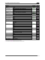
CONTENTS
REFERENCES ............................................................................................................ix
Conventions................................................................................................................. ix
Reference Documentation ........................................................................................... ix
Services and Support .................................................................................................. ix
Patents......................................................................................................................... ix
SAFETY AND COMPLIANCE NOTICES..................................................................... x
FCC Compliance .......................................................................................................... x
Power Supply................................................................................................................ x
CE Compliance............................................................................................................. x
Handling....................................................................................................................... xi
1
1.1
1.1.1
1.1.2
1.1.3
1.2
1.3
1.4
INTRODUCTION ..........................................................................................................1
Configuration Methods..................................................................................................1
Configuration Using Datalogic Aladdin™...................................................................... 1
Configuration Using Serial Programming Strings ......................................................... 1
Configuration Using Programming Barcode Labels...................................................... 1
Button and LED Indicators............................................................................................2
Available Models...........................................................................................................2
Accessories ..................................................................................................................3
2
2.1
2.1.1
2.1.2
2.1.3
2.1.4
2.2
2.2.1
2.2.2
2.2.3
2.3
2.4
2.4.1
2.4.2
2.4.3
INSTALLATION ...........................................................................................................4
TC1200 CCD Scanner..................................................................................................4
Mechanical Installation ................................................................................................. 4
GFC-1200 105° Deflection Mirror ................................................................................. 5
CAB-TC1200 Adaptor Cable ........................................................................................ 7
Electrical Connections ..................................................................................................8
TC1200 CCD Scan Engine......................................................................................... 12
Mechanical Installation ............................................................................................... 12
Electrical Connections ................................................................................................13
USB-KBD Scan Engine Trigger for Barcode Configuration ........................................ 16
Positioning ..................................................................................................................17
Dynamic Code Reading Applications ......................................................................... 18
Line Speed vs. Exposure Time................................................................................... 18
Step-Ladder Applications............................................................................................ 20
Picket-Fence Applications ..........................................................................................21
3
3.1
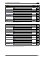
SOFTWARE CONFIGURATION STRINGS............................................................... 22
TC1200 Configuration.................................................................................................22
4
4.1
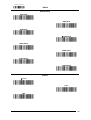
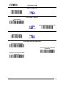
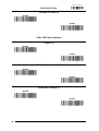
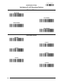
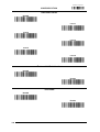
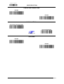
BARCODE CONFIGURATION .................................................................................. 40
Initial Setup .................................................................................................................40
Restore Default...........................................................................................................40
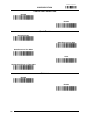
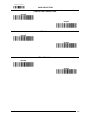
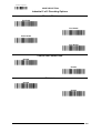
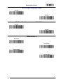
Interface Selection ......................................................................................................40
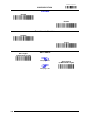
Changing Default Settings ..........................................................................................42
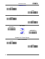
Global Interface Features ...........................................................................................43
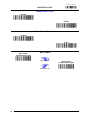
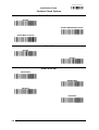
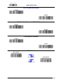
4.2
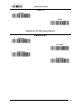
RS232.........................................................................................................................44
Baud Rate...................................................................................................................45
Parity........................................................................................................................... 45
Data Bits .....................................................................................................................46
iii
Stop Bits .....................................................................................................................46
RS232/USB-COM.......................................................................................................47
Intercharacter Delay ...................................................................................................48
Disable Character .......................................................................................................48
Enable Character........................................................................................................48
ACK/NAK Options.......................................................................................................48
ACK Character............................................................................................................48
NAK Character............................................................................................................49
ACK/NAK Timeout ......................................................................................................49
ACK/NAK Retry Count................................................................................................ 49
ACK/NAK Error Handling............................................................................................49
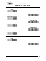
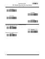
USB-KBD ...................................................................................................................50
Keyboard Country.......................................................................................................51
Keyboard Country (continued).................................................................................... 52
Keyboard Intercode Delay .......................................................................................... 52
Send Control Characters ............................................................................................53
USB Keyboard Speed.................................................................................................53
USB Keyboard Speed (continued).............................................................................. 54
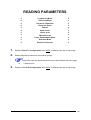
READING PARAMETERS .........................................................................................55
Illumination Mode........................................................................................................56
Operating Mode ..........................................................................................................56
Automatic Threshold...................................................................................................56
Phase Off Event..........................................................................................................57
Timeout.......................................................................................................................57
Serial Start ..................................................................................................................57
Serial Stop ..................................................................................................................57
LED Indication ............................................................................................................57
Label Programming Mode .......................................................................................... 58
Exposure Mode...........................................................................................................58
Reading Conditions ....................................................................................................58
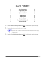
DATA FORMAT .........................................................................................................59
Data Transmission......................................................................................................60
Code Verifier Mode.....................................................................................................60
Match String................................................................................................................60
Wrong Code String .....................................................................................................60
Case Conversion ........................................................................................................61
Global Prefix ...............................................................................................................61
Global Suffix ...............................................................................................................61
No Read String ...........................................................................................................61
Transmit AIM IDs ........................................................................................................62
Transmit Custom Label IDs ........................................................................................62
Custom Label Identifiers .............................................................................................62
Custom Label Identifiers (continued) ..........................................................................63
Custom Label Identifiers (continued) ..........................................................................64
Custom Code Identifiers (continued) .......................................................................... 65
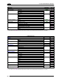
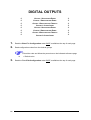
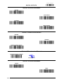
DIGITAL OUTPUTS ...................................................................................................66
Output 1 Activation Event ...........................................................................................67
Output 1 Deactivation Event ....................................................................................... 67
Output 1 Deactivation Timeout ................................................................................... 67
Output 1 Activation Event ...........................................................................................67
iv
Output 2 Activation Event ...........................................................................................68
Output 2 Deactivation Event ....................................................................................... 68
Output 2 Deactivation Timeout ................................................................................... 68
Output 2 Activation Event ...........................................................................................68
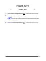
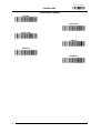
POWER SAVE ...........................................................................................................69
Sleep Mode Timeout...................................................................................................70
CODE SELECTION....................................................................................................71
Positive / Negative Background..................................................................................72
UPC-A.........................................................................................................................73
Check Character Tx....................................................................................................73
Expand to EAN-13 ......................................................................................................73
Number System Tx .....................................................................................................73
UPC-A Minimum Reads.............................................................................................. 74
Coupon Control...........................................................................................................74
UPC-E.........................................................................................................................75
Check Character Tx....................................................................................................75
Expand to UPC-A .......................................................................................................75
Expand to EAN-13 ......................................................................................................75
Number System Tx .....................................................................................................76
UPC-E Minimum Reads.............................................................................................. 76
EAN-13 .......................................................................................................................77
Check Character Tx....................................................................................................77
ISBN Conversion ........................................................................................................77
ISSN Conversion ........................................................................................................77
Flag 1 Character .........................................................................................................78
EAN-13 Minimum Reads ............................................................................................78
Coupon Control...........................................................................................................78
EAN-8 .........................................................................................................................79
Check Character Tx....................................................................................................79
Expand to EAN-13 ......................................................................................................79
EAN-8 Minimum Reads ..............................................................................................79
Enable Optional P2 Add-On ....................................................................................... 80
Enable Optional P5 Add-On ....................................................................................... 80
P2 Minimum Reads ....................................................................................................80
P5 Minimum Reads ....................................................................................................81
Optional Add-On Timer...............................................................................................81
GTIN Format...............................................................................................................82
Decoding Level ...........................................................................................................82
Character Correlation .................................................................................................82
In-Store Minimum Reads ............................................................................................83
Code 39 ......................................................................................................................83
Code 39 Full ASCII .....................................................................................................83
Code Length Control...................................................................................................83
Set Length ..................................................................................................................84
Code 39 Check Tx ......................................................................................................84
Code 39 Start/Stop Tx ................................................................................................84
Code 32 (Italian Pharmaceutical) ............................................................................... 85
Code 32 Check Tx ......................................................................................................85
Code 32 Start/Stop Tx ................................................................................................85
Check Calculation.......................................................................................................86
Minimum Reads.......................................................................................................... 86
Decoding Level ...........................................................................................................87
Character Correlation .................................................................................................87
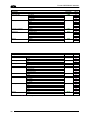
v
Interdigit Ratio.............................................................................................................87
Quiet Zones ................................................................................................................88
Stitching ......................................................................................................................88
Code 128 ....................................................................................................................89
GS1-128 Enable .........................................................................................................89
Code Length Control...................................................................................................89
Set Length ..................................................................................................................89
Expand to Code 39 .....................................................................................................90
Check Tx.....................................................................................................................90
Function Character Tx ................................................................................................90
Sub-Code Change Tx ................................................................................................. 90
Minimum Reads.......................................................................................................... 91
Decoding Level ...........................................................................................................91
Character Correlation .................................................................................................92
Quiet Zones ................................................................................................................92
Stitching ......................................................................................................................92
ISBT 128 Concatenation.............................................................................................93
Concatenation Mode...................................................................................................93
Dynamic Concatenation Timeout................................................................................93
Interleaved 2 of 5 ........................................................................................................94
Code Length Control...................................................................................................94
Set Length ..................................................................................................................94
Check Calculation.......................................................................................................95
Check Tx.....................................................................................................................95
Minimum Reads.......................................................................................................... 96
Decoding Level ...........................................................................................................96
Character Correlation .................................................................................................97
Stitching ......................................................................................................................97
Zero Pattern................................................................................................................97
Standard 2 of 5 ...........................................................................................................98
Code Length Control...................................................................................................98
Set Length ..................................................................................................................98
Check Calculation.......................................................................................................98
Check Tx.....................................................................................................................99
Minimum Reads.......................................................................................................... 99
Decoding Level .........................................................................................................100
Character Correlation ...............................................................................................100
Stitching ....................................................................................................................100
Industrial 2 of 5 .........................................................................................................101
Code Length Control.................................................................................................101
Set Length ................................................................................................................101
Check Calculation.....................................................................................................102
Check Tx...................................................................................................................102
Minimum Reads........................................................................................................ 103
Character Correlation ...............................................................................................103
Stitching ....................................................................................................................103
Codabar ....................................................................................................................104
Code Length Control.................................................................................................104
Set Length ................................................................................................................104
Codabar ABC............................................................................................................105
Concatenation Mode.................................................................................................105
Dynamic Concatenation Timeout..............................................................................105
Check Calculation.....................................................................................................106
Check Tx...................................................................................................................106
Start/Stop Set ...........................................................................................................106
vi
Start/Stop Tx.............................................................................................................107
Start/Stop Match .......................................................................................................107
Minimum Reads........................................................................................................ 107
Decoding Level .........................................................................................................108
Character Correlation ...............................................................................................108
Interdigit Ratio...........................................................................................................108
Quiet Zones ..............................................................................................................109
Stitching ....................................................................................................................109
Code 11 ....................................................................................................................110
Code Length Control.................................................................................................110
Set Length ................................................................................................................110
Check Calculation.....................................................................................................111
Check Tx...................................................................................................................111
Minimum Reads........................................................................................................ 112
Decoding Level .........................................................................................................112
Character Correlation ...............................................................................................113
Interdigit Ratio...........................................................................................................113
Stitching ....................................................................................................................113
GS1 DataBar Omnidirectional ..................................................................................114
GS1 DataBar Omnidirectional GS1-128 Emulation .................................................. 114
Minimum Reads........................................................................................................ 114
GS1 DataBar Expanded ...........................................................................................115
GS1 DataBar Expanded GS1-128 Emulation........................................................... 115
Code Length Control.................................................................................................115
Set Length ................................................................................................................115
Minimum Reads........................................................................................................ 116
Coupon Control.........................................................................................................116
GS1 DataBar Limited................................................................................................117
GS1 DataBar Limited GS1-128 Emulation ............................................................... 117
Minimum Reads........................................................................................................ 117
Code 93 ....................................................................................................................118
Code Length Control.................................................................................................118
Set Length ................................................................................................................118
Check Calculation.....................................................................................................119
Check Tx...................................................................................................................119
Minimum Reads........................................................................................................ 120
Decoding Level .........................................................................................................120
Character Correlation ...............................................................................................121
Quiet Zones ..............................................................................................................121
Stitching ....................................................................................................................121
MSI ...........................................................................................................................122
Code Length Control.................................................................................................122
Set Length ................................................................................................................122
Check Calculation.....................................................................................................123
Check Tx...................................................................................................................123
Minimum Reads........................................................................................................ 124
Decoding Level .........................................................................................................124
Stitching ....................................................................................................................125
Plessey .....................................................................................................................125
Code Length Control.................................................................................................125
Set Length ................................................................................................................125
Check Calculation.....................................................................................................126
Check Tx...................................................................................................................126
Minimum Reads........................................................................................................ 126
Decoding Level .........................................................................................................127
vii
Character Correlation ...............................................................................................127
Stitching ....................................................................................................................127
5
5.1
5.1.1
5.1.2
5.2
5.2.1
5.2.2
5.2.3
5.2.4
5.2.5
5.3
5.3.1
5.3.2
5.3.3
5.4
5.5
5.6
5.6.1
5.6.2
PARAMETER REFERENCES ................................................................................. 128
RS232 Parameters ...................................................................................................128
RS232 Only ..............................................................................................................128
RS232/USB COM Parameters ................................................................................. 129
Reading Parameters.................................................................................................133
Illumination Mode......................................................................................................133
Operating Mode ........................................................................................................134
Good Read LED .......................................................................................................137
Exposure Mode.........................................................................................................137
Preset Recipes .........................................................................................................137
Data Formatting ........................................................................................................138
Global Prefix/Suffix ...................................................................................................139
Code Identifiers.........................................................................................................141
Code Verifier.............................................................................................................144
Digital Outputs ..........................................................................................................145
Power Save ..............................................................................................................146
Code Selection .........................................................................................................146
Concatenation...........................................................................................................148
Set Length ................................................................................................................149
6
6.1
MAINTENANCE .......................................................................................................151
Cleaning....................................................................................................................151
7
7.1
TECHNICAL FEATURES......................................................................................... 152
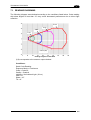
Reading Diagrams ....................................................................................................153
A
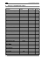
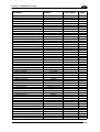
DEFAULT PARAMETERS TABLE..........................................................................154
B
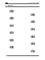
KEYPAD...................................................................................................................158
C
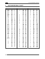
ASCII/HEX/DECIMAL CHART................................................................................. 160
D
RESERVED CHARACTERS.................................................................................... 162
viii
REFERENCES
CONVENTIONS
This manual uses the following conventions:
“User” or “Operator” refers to anyone using a TC1200.
“Device” refers to the TC1200.
“You” refers to the System Administrator or Technical Support person using this manual to
install, mount, operate, maintain or troubleshoot a TC1200.
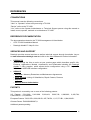
REFERENCE DOCUMENTATION
The documentation related to the TC1200 management is listed below:
GFC-TC1200 Installation Manual
Datalogic Aladdin™ Help On Line
SERVICES AND SUPPORT
Datalogic provides several services as well as technical support through its website. Log on
to www.automation.datalogic.com and click on the links indicated for further information:
PRODUCTS
Search through the links to arrive at your product page which describes specific Info,
Features, Applications, Models, Accessories, and Downloads including the Datalogic
Aladdin™ utility program, which allows device configuration using a PC. It provides
RS232 and USB-COM interface configuration.
SERVICE
- Overview - Warranty Extensions and Maintenance Agreements
- Sales Network- Listing of Subsidiaries, Repair Centers, Partners
- Helpdesk
- Material Return Authorization
PATENTS
This product is covered by one or more of the following patents:
US Patents: 5,311,000; 5,481,098;
6,443,360 B1; 7,075,663 B2.
5,929,421;
5,992,740;
6,098,883;
6,260,764;
European Patents: 789,315 B1; 926,620 B1; 997,760 B1; 1,217,571 B1; 1,804,089 B1.
Chinese Patent: ZL200680050007,8.
Additional patents pending.
ix
SAFETY AND COMPLIANCE NOTICES
FCC COMPLIANCE
Modifications or changes to this equipment without the expressed written approval of
Datalogic could void the authority to use the equipment.
This device complies with PART 15 of the FCC Rules. Operation is subject to the following
two conditions: (1) This device may not cause harmful interference, and (2) this device must
accept any interference received, including interference which may cause undesired
operation.
This equipment has been tested and found to comply with the limits for a Class A digital
device, pursuant to part 15 of the FCC Rules. These limits are designed to provide
reasonable protection against harmful interference when the equipment is operated in a
commercial environment. This equipment generates, uses, and can radiate radio frequency
energy and, if not installed and used in accordance with the instruction manual, may cause
harmful interference to radio communications. Operation of this equipment in a residential
area is likely to cause harmful interference in which case the user will be required to correct
the interference at his own expense.
POWER SUPPLY
This product is intended to be installed by Qualified Personnel only.
This accessory device is intended to be supplied by a UL Listed or CSA Certified Power Unit
with «Class 2» or LPS power source, which supplies power directly to the scanner via the 9pin or USB connector.
CE COMPLIANCE
Warning:
This is a Class A product. In a domestic environment this product may cause radio
interference in which case the user may be required to take adequate measures.
x
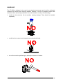
HANDLING
The TC1200 is designed to be used in an industrial environment and is built to withstand
vibration and shock when correctly installed, however it is also a precision product and
therefore before and during installation it must be handled correctly to avoid damage.
avoid that the scanners hit one another causing damage. They should be handled
separately.
avoid that the scanners are dropped (exceeding shock limits).
do not fine tune the positioning by striking the scanner or bracket.
xi
do not weld the scanner into position which can cause electrostatic, heat or output
window damage.
do not spray paint near the scanner which can cause output window damage.
xii
INTRODUCTION
1
1 INTRODUCTION
The TC1200 compact CCD reader is the perfect solution for many OEM applications. It
contains a built-in decoder and multi-standard interface. Due to its well-balanced mix of
technical characteristics it is perfect for integration into custom equipment, setting a new
standard in this product class.
This Reference Manual provides connection diagrams, default parameter listing, complete
application parameter settings, specific technical features and reading diagrams.
1.1 CONFIGURATION METHODS
1.1.1
Configuration Using Datalogic Aladdin™
(for RS232/USB-COM Interfaces)
The easiest way to configure TC1200 is by using the Datalogic Aladdin™ utility program
downloadable from: www.automation.datalogic.com.
Aladdin allows you to program the TC1200 reader by selecting configuration commands
through a user-friendly graphical interface running on a PC. These commands are sent to the
reader over the selected communication interface, or they can be printed as barcodes to be
scanned.
Aladdin also provides Help On-Line files explaining how to use the program as well as
descriptions of the configuration parameters.
Aladdin also provides the ability to perform a software upgrade for the connected device (see
the Datalogic Aladdin™ Help On-Line for more details).
1.1.2
Configuration Using Serial Programming Strings
(for RS232/USB-COM Interfaces)
This manual contains the complete set of command strings for TC1200 configuration. These
strings can be sent via the RS232/USB-COM interface using a terminal emulator such as
HyperTerminal.
Refer to Chapter 3 of this manual for configuration procedures using Serial Strings sent by
the Host.
1.1.3
Configuration Using Programming Barcode Labels
(for all Interfaces)
Refer to Chapter 4 of this manual for configuration procedures using Programming Bacode
Labels.
1
TC1200 REFERENCE MANUAL
1
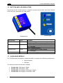
1.2 BUTTON AND LED INDICATORS
On the face of the TC1200 scanner a keypad is present with a button and three indicator
LEDs which are described in the table below.
TC1200 Scanner
TC1200 Keypad
INDICATORS
Color
MEANING
POWER LED
Blue
GOOD Read LED
Green
TRIGGER LED
Yellow
ON = Power ON
OFF = Power OFF or standby (only USB model)
ON = Good Read
OFF = No Read
Blinks = USB enumeration
ON = External trigger or button pressed
OFF = No trigger
Press for manual trigger
Button
1.3 AVAILABLE MODELS
The TC1200 reader is available in models that differ in regard to the following characteristics:
Output Interface
Enclosure
The following models are therefore available:
2
TC1200-1000 CCD Reader, RS232
TC1200-1100 CCD Reader, USB
TC1200-0000 Scan Engine CCD Reader, RS232
TC1200-0100 Scan Engine CCD Reader, USB
INTRODUCTION
1
1.4 ACCESSORIES
The following accessories are available to simplify installation and optimize product
performance:
Name
Description
Part Number
CAB-TC1200
CBX Adapter Cable 10-30 Vdc Power Supply
93A051388
CAB-TC1200
to C-BOX 25-p D-sub Fem (TC1100 Compatible) 93A050026
GFC-1200
105° Deflection Mirror for TC1200
93ACC1891
The TC1100 Compatible cable does not provide 10-30 Vdc to 5 Vdc
conversion. TC1200 must be powered only with 5 Vdc.
NOTE
3
TC1200 REFERENCE MANUAL
2
2 INSTALLATION
2.1 TC1200 CCD SCANNER
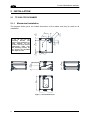
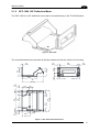
2.1.1
Mechanical Installation
6
[0.24]
8
[0.30]
25
[0.98]
57
[2.24]
18.7
[0.736]
31
[1.22]
Optical Axis
50
[1.97]
Figure 1 - Overall Dimensions
4
11
[0.44]
8
[0.31]
M3x4 N°4
45
[1.77]
If you do not use the
mounting
bracket
and
screws in the packaging, to
avoid damage to the
product case and internal
components, make sure
that mounting screws do
not exceed the threaded
hole depth of 4 mm.
8
[0.30]
11 43]
.
[0
6
[0.24]
The diagram below gives the overall dimensions of the reader and may be used for its
installation.
INSTALLATION
2.1.2
2
GFC-1200 105° Deflection Mirror
The GFC-1200 is a 105° deflection mirror that is mounted directly to the TC1200 Scanner.
Figure 2 - GFC-1200
The overall dimensions are provided in the figure below and can be used for its mounting.
2.0
[0.08]
13.0
[0.51]
53.0
[2.09]
23.0
[0.91]
5.0
[0.20]
5.0
[0.20]
5.0
[0.20]
15.0
[0.59]
11.0
[0.43]
5.0
[0.20]
77
[3.03]
5.0
[0.20]
45.0
[1.77]
67.0
[2.64]
5.0
[0.20]
11.0
[0.43]
5.0
[0.20]
77
[3.03]
67.0
[2.64]
15.0
[0.59]
31.5
[1.24]
33
[1.30]
5.0
[0.20]
5.0
[0.20]
28.0
[1.10]
Figure 3 - GFC-1200 Overall Dimensions
5
TC1200 REFERENCE MANUAL
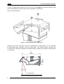
2
To fix a TC1200-1x00 Scanner to the GFC-1200, use two M3x5 mm screws included in the
GFC-1200 package. An extra screw is also supplied as a spare part.
Refer to the figure below.
Figure 4 – Fixing TC1200 Scanner to GFC-1200
Based upon the 105° orientation, this mirror embeds the 15° skew angle (± 1.5°), necessary
to avoid direct light reflection from the target label. This feature allows mounting the
TC1200+GFC-1200 group parallel to the target surface, keeping the overall mounting space
to a minimum.
20.7
[0.81]
68
[2.69]
15°
Target label
Figure 5 – Maintaining Minimum Skew Angle
6
INSTALLATION
2.1.3
2
CAB-TC1200 Adapter Cable
In order to connect the TC1200 to a CBX100 connection box, you can use the CAB-TC1200
adapter cable. This cable converts the 10-30 Vdc system power to the 5 Vdc necessary for
the TC1200 reader. The cable has the following pinout:
25-Pin Connector
13,9
VDC
Power supply input voltage + (10-30 Vdc)
25,7
GND
Power supply input voltage -
1
SHIELD
Cable Shield
18
EXT TRIG A
External Trigger A (polarity insensitive)
19
EXT TRIG B
External Trigger B (polarity insensitive)
8
OUT1 +
Output 1 positive
11
OUT2 +
Output 2 positive
12,22
OUT1/2 -
Output 1/2 negative
20
RX
Receive data (RS232 Aux on CBX)
21
TX
Transmit data (RS232 Aux on CBX)
2,3,4,5,6,10,23,24 NC
Not connected
Power Supply (10-30 Vdc)
TC1200
CBX100
Host
CAB-TC1200
photocell
Figure 6 – Typical Layout Using CAB-TC1200
7
TC1200 REFERENCE MANUAL
2
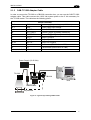
2.1.4
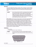
Electrical Connections
The TC1200-1000 Scanner is equipped with a 9-pin Male D-Sub connector for connection to
the power supply and input/output signals. The details of the connector pins are indicated in
the following table:
Figure 7 - 9-pin Male D-sub Connector
1
2
3
4
5
6
7
8
9
VCC
GND
RX
TX
OUT1 +
OUT1/2 OUT2 +
EXT TRIG A
EXT TRIG B
9-pin Connector
+5 Vdc
Ground
Receive Data
Transmit Data
Output signal 1, positive
Output signal 1/2, negative
Output signal 2, positive
External Trigger Input (polarity insensitive)
External Trigger Input (polarity insensitive)
Table 1 - TC1200-1000 Scanner Pinout
The TC1200-1100 Scanner is equipped with a USB Type A connector for connection to the
PC standard USB Port. The details of the connector pins are indicated in the following table:
Figure 3 – USB Type A Connector
1
2
3
4
VCC
DATA DATA +
GND
USB Type A Connector
+5 Vdc
USB Data, negative
USB Data, positive
Ground
Table 2 - TC1200-1100 Scanner Pinout
8
INSTALLATION
2
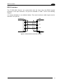
RS232 Interface
The TC1200-1000 Scanner can communicate with the Host using the RS232 signals
provided on the 9-pin connector. The pins are indicated in Table 1 and in the following
diagram:
It is always advisable to use shielded cables. The overall maximum cable length must be
less than 15 m (49.2 ft).
TC1200 9-pin
Host
4
TX
3
RX
2
GND
RXD
TXD
GND
Earth
Ground
Figure 8 - RS232 Interface Connection to Host
9
TC1200 REFERENCE MANUAL
2
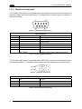
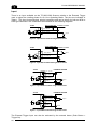
Input
There is an input available on the TC1200-1000 Scanner relative to the External Trigger
used to signal the reading phase for On Line Operating Mode. The pins are indicated in
Table 1. This input is optocoupled, polarity insensitive and can be driven by both an NPN or
PNP type command. The connections are indicated in the following diagrams:
Vext 30 Vdc max.
TC1200
V CC
+
~
~
-
8
EXT TRIG A
9
EXT TRIG B
EXTERNAL TRI GGER
V
Signal
Figure 4 - Input NPN Command Using External Power
Vext 30 Vdc max. EXTERNAL TRI GGER
TC1200
V
V CC
+
~
~
-
8
EXT TRIG A
9
EXT TRIG B
Signal
Figure 5 - Input PNP Command Using External Power
TC1200
V CC
+
EXTERNAL TRIGGER
~
~
-
1
Vcc (5 Vdc)
8
EXT TRIG A
9
EXT TRIG B
2
GND
V
Signal
Ground
Figure 6 - Input NPN Command Using TC1200 Power
TC1200
V CC
+
EXTERNAL TRIGGER
~
~
-
1
Vcc (5 Vdc )
8
EXT TR IG A
9
EXT T RIG B
2
GND
V
Signal
Ground
Figure 7 - Input PNP Command Using TC1200 Power
The External Trigger Input can also be activated by the external button (Push Button =
Trigger On).
10
INSTALLATION
2
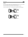
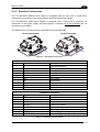
Outputs
There are two outputs available on the TC1200-1000 Scanner. Each output can be activated
on one of the following events: Good Read, No Read, Wrong Code.
The active level (high or low) of each Output can also be configured in software.
The pins are indicated in Table 1. The connections are indicated in the following diagram:
TC1200
USER IN TERF ACE
5
OUT1 +
6
OUT1/2 -
Ve xt 30 Vdc ma x
Figure 9 – Output1 Connection. Example NPN
TC1200
USER IN TERF ACE
7
OUT2 +
6
OUT1/2 -
Ve xt 30 Vdc ma x
Figure 9 – Output2 Connection. Example NPN
11
TC1200 REFERENCE MANUAL
2
2.2 TC1200 CCD SCAN ENGINE
2.2.1
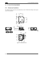
Mechanical Installation
The diagram below gives the overall dimensions of the TC1200 Scan Engine and may be
used for its installation.
5
[0.20]
3.1
[0.12]
31
[1.22]
31.1
[1.22]
20.8
[0.82]
12.7
[0.50]
3
[0.12]
Ø2.3
[Ø0.09] N°3
39
[1.54]
44
[1.73]
3
[0.12]
34
[1.34]
J1
8
1
10
50
[1.97]
16.8
[0.66]
4.8
[0.19]
9.3
[0.36]
J2
1
1.5
[0.06]
Optical Axis
43
[1.69]
Figure 10 - Overall Dimensions
12
INSTALLATION
2.2.2
2
Electrical Connections
The TC1200-0000 (RS232) Scan Engine is equipped with an 8-pin and a 10-pin DF13
connector for connection to the power supply, data and input/output signals.
The TC1200-0100 (USB) Scan Engine is equipped with a 10-pin DF13 connector for
connection to the power supply and data signals. Connector J2 is not mounted and I/O
signals are not available.
The details of the connector pins are indicated in the following table:
TC1200-0000 (RS232)
TC1200-0100 (USB)
10
8
1
1
10
1
J1
J1
J2
Figure 10 – Scan Engine Connectors
Pin
1
2
3
4
5
6
7
8
9
10
Pin
1
2
3
4
5
6
7
8
Signal
DD+
GND
GND
TX
RTS
RX
CTS
VCC
GND
Signal
GND
OUT2 +
OUT1/2 OUT1 +
EXT TRIG A
EXT TRIG B
J1
Description
USB Data negative
USB Data positive
power ground
power ground
transmit data
NOT USED
receive data
NOT USED
+5 Vdc
power ground
J2 (RS232 model Only)
Description
power ground
NC
Output 2 positive
Output 1/2 negative
Output 1 positive
NC
External Trigger Input (polarity insensitive)
External Trigger Input (polarity insensitive)
Table 3 - TC1200 Scan Engine Pinout
13
TC1200 REFERENCE MANUAL
2
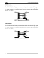
RS232 Interface
The TC1200-0000 Scan Engine can communicate with the Host using the RS232 signals
provided on the J1 connector. The pins are indicated in Table 1 and in the following diagram:
It is always advisable to use shielded cables. The overall maximum cable length must be
less than 15 m (49.2 ft).
TC1200
J1
Host
5
TX
7
RX
10
GND
RXD
TXD
GND
Earth
Ground
Figure 12 - RS232 Interface Connection to Host
USB Interface
The TC1200-0100 Scan Engine can communicate with the Host using the USB signals
provided on the J1 connector. The pins are indicated in Table 1 and in the following diagram:
It is always advisable to use shielded cables. The overall maximum cable length must be
less than 15 m (49.2 ft).
TC1200
J1
Host
1
D-
2
D+
9
VCC
10
GND
DD+
VCC
GND
Earth
Ground
Figure 13 - USB Interface Connection to Host
14
INSTALLATION
2
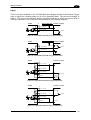
Input
There is an input available on the TC1200-0000 Scan Engine relative to the External Trigger
used to signal the reading phase for On Line Operating Mode. The pins are indicated in
Table 1. This input is optocoupled, polarity insensitive and can be driven by both an NPN or
PNP type command. The connections are indicated in the following diagrams:
TC1200
V CC
+
J2
~
~
-
Vext 30 Vdc max. EXTERNAL TRI GGER
7
EXT TRIG A
8
EXT TRIG B
V
Signal
Figure 14 - Input NPN Command Using External Power
Vext 30 Vdc max. EXTERNAL TRI GGER
TC1200
V
J2
V CC
+
~
~
-
7
EXT TRIG A
8
EXT TRIG B
Signal
Figure 15 - Input PNP Command Using External Power
TC1200
EXTERNAL TRI GGER
J1
9
Vcc (5 Vdc)
V
J2
V CC
+
~
-
~
7
EXT TRIG A
8
EXT TRIG B
10
GND
Signal
Ground
Figure 15 - Input NPN Command Using TC1200 Power
TC1200
EXTERNAL TRI GGER
J1
9
Vcc (5 Vdc)
V
J2
V CC
+
~
~
-
7
EXT TRIG A
8
EXT TRIG B
10
GND
Signal
Ground
Figure 16 - Input PNP Command Using TC1200 Power
15
TC1200 REFERENCE MANUAL
2
Outputs
There are two outputs available on the TC1200-0000 Scan Engine. Each output can be
activated on one of the following events: Good Read, No Read, Wrong Code.
The active level (high or low) of each Output can also be configured in software.
The pins are indicated in Table 1. The connections are indicated in the following diagram:
TC1200
USER IN TERF ACE
J2
5
OUT1 +
4
OUT1/2 -
Ve xt 30 Vdc ma x
Figure 17 – Output1 Connection. Example NPN
TC1200
USER IN TERF ACE
J2
3
OUT2 +
4
OUT1/2 -
Ve xt 30 Vdc ma x
Figure 18 – Output2 Connection. Example NPN
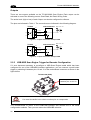
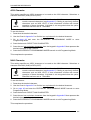
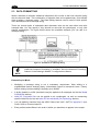
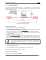
2.2.3
USB-KBD Scan Engine Trigger for Barcode Configuration
If it ever becomes necessary to reconfigure a USB Scan Engine model which has been
configured for one of the USB-KBD Interface applications, you can connect a push button
trigger by soldering it between pins 12 and 13 of the motherboard connector as shown in the
figure below.
TC1200-0100 (USB)
Solder a pushbutton
between pins 12 and 13
You must be careful not to short out other pins or components.
CAUTION
It is recommended to return to the USB-COM interface and choose one of the serial
configuration methods. Then you can restore the USB-KBD selection.
16
INSTALLATION
2
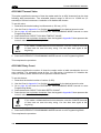
2.3 POSITIONING
The TC1200 Scanner is able to decode barcode labels at a variety of angles, however
significant angular distortion may degrade reading performance.
When mounting the TC1200 take into consideration these three ideal label position angles: Pitch
0°, Skew 10° to 30° and Tilt 0°. Follow the suggestions for the best orientation:
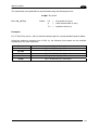
The Pitch angle is represented by the value P in the figure. Position the reader in order to
minimize the Pitch angle.
P
Figure 19 - Pitch Angle
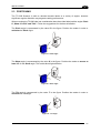
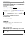
The Skew angle is represented by the value S in the figure. Position the reader to assure at
least 10° for the Skew angle. This avoids direct light reflection.
S
Figure 20 - Skew angle
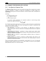
The Tilt angle is represented by the value T in the figure. Position the reader in order to
minimize the Tilt angle.
T
Figure 21 - Tilt angle
17
TC1200 REFERENCE MANUAL
2
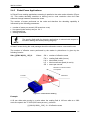
2.4 DYNAMIC CODE READING APPLICATIONS
2.4.1
Line Speed vs. Exposure Time
The Exposure Time defines the time during which the image will be exposed to the reader's
sensor for acquisition. In general, a longer time corresponds to a lighter image but is
susceptible to blurring due to the code movement; a shorter exposure time corresponds to a
darker image.
Assuming:
X: Code Resolution (mm)
Texp: Exposure Time (s)
LS: Line Speed (mm/s)
for dynamic reading applications, the essential condition to avoid blurring effects
between two adjacent elements is:
LS Texp X
For TC1200, the maximum exposure time is 300 s in a dark environment (no ambient light)
using Strobed Exposure Mode. This value, and therefore line speed, is affected by the
following environmental conditions:
Code Resolution: a decrease in code resolution, (i.e. 2X) allows an increase in
maximum line speed. There is a decrement of overlapping effects between two adjacent
elements.
Code/Background Contrast: a decrease in image contrast (poor quality codes,
reflective transparent coverings, different supports and printing techniques) requires a
decrease in maximum line speed.
Ambient Light: an increase in external lighting conditions allows an increase in
maximum line speed.
Reading Distance: an increase or decrease in reading distance with respect to the
center of the focal distance for a given code resolution, (see reading diagram), requires a
decrease in maximum line speed.
These environmental conditions are automatically compensated for by one of the selected
Reading Condition Recipes (see par 5.2.5. for more details), as well as by the Exposure
Mode parameter (see par. 5.2.4 for more details).
18
INSTALLATION
2
The (theoretical) line speed LS can be calculated using the following formula:
0.8 X / Texp = LS
LS = 0.8 * (X/Texp)
Where:
LS =
X
=
Texp =
line speed (in mm/s)
code module width (in mm)
exposure time (in s)
Examples:
For TC1200, Texp max is = 300 s with No Ambient Light (0 Lux) and Strobed Exposure Mode.
Using the maximum exposure time of 300 s, the following line speeds can be obtained
depending on the code resolution:
Code Resolution
20 mils
Line Speed Calculation
[0.8 * 0.508/300 s] = 1354 mm/s
14 mils
[0.8 * 0.356/300 s] = 949 mm/s
12 mils
[0.8 * 0.305/300 s] = 813 mm/s
10 mils
[0.8 * 0.254/300 s] = 677 mm/s
8 mils
[0.8 * 0.203/300 s] = 541 mm/s
19
TC1200 REFERENCE MANUAL
2
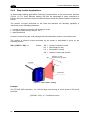
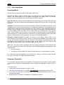
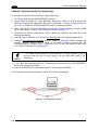
2.4.2
Step-Ladder Applications
In Step-Ladder reading applications scanning is perpendicular to the code motion direction
(Figure 11). For linear barcode reading, this has the advantage of being insensitive to
blurring and code resolution since the code elements remain the same between consecutive
scans.
The number of scans performed on the code and therefore the decoding capability is
influenced by the following parameters:
number of scans per second (320 scans/sec. max)
line speed (code motion) see par. 2.4.1
label dimensions
At least 5 scans during the code passage should be allowed to ensure a successful read.
The number of effective scans performed by the reader in step-ladder is given by the
following formula:
SN = [(LH/LS) * SS] – 2
Where:
SN
LH
LS
SS
=
=
=
=
number of effective scans
label height (in mm)
line speed in (mm/s)
number of scans per second
Direction of code
movement at LS speed
TC1200
LH
Illuminator
Figure 11 - "Step-Ladder" Reading
Example:
The TC1200 (320 scans/sec.), for a 25 mm high code moving at a line speed of 500 mm/s
performs:
[(25/500) * 320] - 2 = 14 effective scans.
20
INSTALLATION
2.4.3
2
Picket-Fence Applications
In Picket-Fence reading applications scanning is parallel to the code motion direction (Figure
12). This makes decoding sensitive to blurring and to code resolution since the code
elements change between consecutive scans.
The number of scans performed on the code and therefore the decoding capability is
influenced by the following parameters:
number of scans per second (320 scans/sec. max)
line speed (code motion) see par. 2.4.1
label dimensions
reading field width
The reading field width for dynamic applications is reduced with respect to
the static reading field width (reading diagram).
NOTE
At least 5 scans during the code passage should be allowed to ensure a successful read.
The number of effective scans performed by the reader in picket-fence is given by the
following formula:
SN = [((FW-LW)/LS) * SS] -2
Where:
SN
FW
LW
LS
SS
=
=
=
=
=
number of effective scans
reading field width (in mm)
label width (in mm)
label movement speed (in mm/s)
scans per second
Direction of code movement
at LS speed
TC1200
Illuminator
LW
FW
Figure 12 - "Picket-Fence" Reading
Example:
A 60 mm wide code moving in a point where the reading field is 160 mm wide at a 1000
mm/s line speed, the TC1200 (320 scans per sec.), performs:
[((160-60)/1000) * 320] - 2 = 30 effective scans
21
TC1200 REFERENCE MANUAL
3
3 SOFTWARE CONFIGURATION STRINGS
3.1 TC1200 CONFIGURATION
TC1200 RS232 models (as well as USB models having the USB-COM Interface selected),
can be configured using the serial strings contained in this chapter:
RS232 Models
To configure TC1200 RS232 models by using the configuration strings:
1) Connect your TC1200 to a PC RS232 port according to the information in chapter 2.
Set the PC serial port to the TC1200 default RS232 communication parameters (see
Appendix A).
NOTE
To configure the reader using configuration strings, you must enter Service
Mode which automatically sets the reader communication parameters to
115200,N,8,1. You must therefore set the host accordingly for RS232
communications. Upon exiting Service Mode, the programmed
communication parameters will be restored.
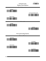
2) Using a Terminal Emulation Program, send the Restore Current Interface (Custom)
Default string to the reader using the syntax described on the next page.
3) Send all the necessary command strings according to your application's requirements.
USB Models
To configure TC1200 USB models (only for USB-COM Interface) by using the
configuration strings:
1) Download and install the USB-COM driver from the TC1200 product page at
www.automation.datalogic.com, (bundled with the Aladdin program).
2) Connect your TC1200 to a PC USB port according to the information in chapter 2.
3) Using a Terminal Emulation Program, send the Enter Service Mode command
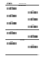
4) Send the Restore Current Interface (Custom) Default string to the reader using the
syntax described on the next page.
5) Send all the necessary command strings according to your application's requirements.
Configuration of TC1200 USB-KBD Interface
accomplished by reading the barcodes in chapter 4.
NOTE
22
applications,
can
be
SOFTWARE CONFIGURATION STRINGS
3
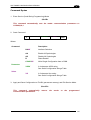
Command Syntax
1. Enter Service (Serial String Programming) Mode
$S<CR>
This command automatically sets the reader communication parameters to
115200,N,8,1.
2. Send Command
$
Command
Parameter
Value
<CR>
Where:
Command:
Description
HAXX
Interface Selection
AA
Enable All Symbologies
AD
Disable All Symbologies
R
Reset Reader
CXXXXXX
Write Single Configuration Item to RAM
XXXX
A 4-character ASCII string
See Serial Configuration Strings Table
XX
A 2-character Hex string
See Serial Configuration Strings Table
Parameter:
Value:
3. Apply and Save Configuration to FLASH (permanent memory) and Exit Service Mode
$Ar<CR>
This command automatically
communication parameters.
returns
the
reader
to
the
programmed
23
TC1200 REFERENCE MANUAL
3
Example 1:
1.
$S<CR>
Enter Service Mode
2.
$CLFCA02<CR>
Write command "Convert to Lower Case" to current configuration
3.
$Ar<CR>
Apply and Save Configuration to FLASH (permanent memory) and Exit Service
Mode.
Each configuration parameter setting removes the condition previously active for that
parameter.
Example 2:
1. $S<CR>
Enter Service Mode
2. $HA05<CR>
Select RS232 Interface
3. $Ar<CR>
Apply and Save Configuration to FLASH (permanent memory) and Exit Service
Mode.
Example 3:
1. $+$!<CR>
Read Application Software Release
Example 4:
1. $S<CR>
Enter Service Mode
2. $CSTON5500000000000000000000000000000000000000<CR>
Set Serial START string to the single character "U". (20 characters max).
NOTE
24
For commands requiring string values, you must enter the complete string
(maximum number of characters) for that command. This is done by filling
the unused characters with zeros (NUL).
SOFTWARE CONFIGURATION STRINGS
3
SERIAL CONFIGURATION STRINGS
ENTER/EXIT CONFIGURATION COMMANDS
Description
Enter Service Mode (configuration) sets communication parameters to 115200,N,8,1
Exit Service Mode (configuration) returns to programmed communication parameters
Apply Configuration to RAM (temporary memory) and Exit Service Mode
Apply and Save Configuration to FLASH (permanent memory) and Exit Service Mode
NOTE
To configure the reader using configuration strings, you must enter Service
Mode which automatically sets the reader communication parameters to
115200,N,8,1. You must therefore set the host accordingly for RS232
communications. Upon exiting Service Mode, the programmed
communication parameters will be restored.
CONFIGURATION COMMANDS
Description
Write Single Configuration Item to RAM (temporary memory)
Read Single Configuration Item from RAM (temporary memory)
Reset Reader
Read Application Software Release (does not require Enter/Exit Service Mode)
Host Commands Obey
Host Commands Ignore
Enable all Symbologies
Disable all Symbologies
NOTE
Command
S
s
r01
Ar
Command
Cxxxxxx
cxxxx
R
$+$!
CIFIH00
CIFIH01
AA
AD
To read a particular parameter setting from the reader, send the read
parameter command without any value. The reader will respond with its
currently configured value.
The Read Application Software Release command is a direct command that
does not require entering Service Mode.
NOTE
INTERFACE SELECTION COMMANDS
Description
Restore Current Interface (Custom) Default Configuration
RS232
USB-COM
USB-KBD
USB-KBD-ALT
USB KBD-APPLE
Command
HA00
HA05
HA47
HA35
HA2B
HA2C
The Interface Selection commands store and load the new interface type
with its factory defaults into the current configuration.
NOTE
25
TC1200 REFERENCE MANUAL
3
RS232 ONLY PARAMETERS
Description
Baud Rate
Parity
Data Bits
Stop Bits
Parameter
R2BA
1200
2400
4800
9600
19200
38400
57600
115200
none
even
odd
7
8
1
2
R2PA
R2DA
R2ST
Value
00
01
02
03
04
05
06
07
00
01
02
00
01
00
01
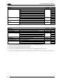
RS232/USB-COM PARAMETERS
Description
Intercharacter Delay
Disable Character
Enable Character
ACK/NAK Options
ACK Character
NAK Character
ACK/NAK Timeout Value
ACK/NAK Retry Count
ACK/NAK Error Handling
No delay or from 10 to 990 ms
host command character which disables the reader
host command character which enables the reader
disable
enable for label transmission
enable for host command acknowledge
enable for label transmission and host command acknowledge
Selects character to be used as ACK
Selects character to be used as NAK
No timeout or from 200 to 15000 ms
From 0 to unlimited retries
Ignore errors detected
Process errors as valid ACK character
Process errors as valid NAK character
Parameter
R2IC
R2DC
R2EC
R2AE
R2AC
R2NA
R2AT
R2AR
R2EH
Value
a
b
b
00
01
02
03
c
c
d
e
00
01
02
a = Hex value from 00 to 63 representing the decimal number (00 = no delay; all others x10 ms)
b = Hex value from 00 to FE representing the ASCII character
c = Hex value from 00 to FF representing the ASCII character
d = Hex value from 00 to 4B representing the decimal number (00 = timeout disabled; all others x200 ms)
e = Hex value from 00 to FF representing the number of retries (00 = no retries; 01-FE = 1-254 retries; FF = unlimited retries)
26
SOFTWARE CONFIGURATION STRINGS
3
USB-KBD / USB-KBD-ALT / USB-KBD-APPLE PARAMETERS
Description
Keyboard Country Mode
Keyboard Intercode Delay
Send Control Characters
USB Keyboard Speed
*US
*Belgium
*Britain
Croatia
Czechoslovakia
Denmark
*France
*Germany
Hungary
*Italy
Japanese (106 key)
Norway
Poland
Portugal
Romania
Slovakia
*Spain
*Sweden
Switzerland
No delay or from 1 to 99 seconds
CTRL + KEY
CTRL + SHIFT + KEY
Special Function KEY
1 ms
2 ms
3 ms
4 ms
5 ms
6 ms
7 ms
8 ms
9 ms
10 ms
Parameter
KBCO
KBID
KBSC
KBSP
Value
00
01
02
11
0E
03
04
05
0D
06
0C
07
12
08
10
0F
09
0A
0B
f
00
01
02
01
02
03
04
05
06
07
08
09
0A
f = Hex value from 00 to 63 representing the decimal number (00 = no delay; all others x1 s)
* = Valid for USB-KBD-APPLE
27
TC1200 REFERENCE MANUAL
3
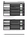
READING PARAMETERS PARAMETERS
Description
Illumination Mode
Operating Modes
Automatic Threshold
Phase Off Event
Timeout
Serial Start
Serial Stop
LED Indication
Label Programming Mode
Exposure Mode
Reading Conditions
Disabled
Triggered
Enabled
On Line
Serial On Line
Automatic
Automatic (Object Sense)
Test
From 2 to 255 scans without a code
Trigger Stop
Timeout
Trigger Stop-Timeout
From 40 to 5100 ms
Any string of characters (max 20) between 00-FE
Any string of characters (max 20) between 00-FE
On Decode
After Transmission
Disabled
Enabled
Continuous
Strobed
Auto
Standard
High Resolution (Far)
Difficult
Blurred (Near)
Parameter
SPIL
SNRM
SNAT
SNTO
SNET
STON
STOF
BPIN
FAPM
SPST
SNCO
Value
00
01
02
00
01
02
03
04
g
00
01
02
h
i
i
00
01
00
01
00
01
00
01
02
03
04
g = Hex value from 02 to FF representing the number of scans without a code
h = Hex value from 02 to FF representing the decimal number (x20 ms)
i = Hex value from 00 to FE representing the ASCII character
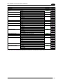
DATA FORMAT
Description
Data Transmission
Code Verifier Mode
Match String
Wrong Code String
Case Conversion
Global Prefix (Header)
Global Suffix (Terminator)
No Read String
Character Conversion
Transmit AIM IDs
Transmit Custom Label IDs
GS1-128 AIM ID
On Decode
After Phase Off
Disabled
Transmit Wrong String
Transmit Wrong Code
Any string of characters (max 20) between 00-FE
Any string of characters (max 20) between 00-FE
Disable
Upper Case
Lower Case
Any string of characters (max 20) between 00-FE
Any string of characters (max 20) between 00-FE
Any string of characters (max 20) between 00-FE
An 8-character string between 00-FF
Disable
Enable
Disable
Prefix
Suffix
Disable
Enable
k = Hex value from 00 to FE representing the ASCII character
m = 8 Hex values from 00 to FF representing the 8 ASCII characters (FF = no replacement or ignore)
28
Parameter
LFTX
LFCV
COVS
WCVS
LFCA
LFPR
LFSU
NORS
LFCH
AIEN
IDCO
U8AI
Value
01
00
00
01
02
k
k
00
01
02
k
k
k
m
00
01
00
01
02
00
01
SOFTWARE CONFIGURATION STRINGS
3
DATA FORMAT
Description
Custom Code Identifiers
UPC-A
UPC-E
EAN-8
EAN-13
UPC-A/P2
UPC-A/P5
UPC-E/P2
UPC-E/P5
EAN-8/P2
EAN-8/P5
EAN-13/P2
EAN-13/P5
ISBN
ISSN
GTIN for EAN/UPC w/o Add-On
GTIN for EAN/UPC w P2
GTIN for EAN/UPC w P5
Code 39
Code 32
Code 128
GS1-128
ISBT 128
Interleaved 2 of 5
Standard 2 of 5
Codabar
ABC Codabar
Code 11
GS1 Databar 14 (Omnidirectional)
GS1 Databar Expanded
GS1 Databar Limited
Code 93
MSI
Parameter
Value
ABID
EBID
8BID
3BID
A2ID
A5ID
E2ID
E5ID
82ID
85ID
32ID
35ID
ISID
INID
GBID
G2ID
G5ID
C3ID
P3ID
C8ID
U8ID
I8ID
I2ID
S2ID
CBID
ACID
C1ID
4BID
XBID
LBID
C9ID
MSID
k
k
k
k
k
k
k
k
k
k
k
k
k
k
k
k
k
k
k
k
k
k
k
k
k
k
k
k
k
k
k
k
Parameter
Value
Disable
Good Read
No Read
Wrong Code
Disable
Timeout
Reading Phase Active
100 to 25500 ms
Closed
Open
OUA1
00
01
02
03
00
01
02
n
00
01
Disable
Good Read
No Read
Wrong Code
Disable
Timeout
Reading Phase Active
100 to 25500 ms
Closed
Open
OUA2
Any string of characters (max 3) between 00-FE
k = Hex value from 00 to FE representing the ASCII character
DIGITAL OUTPUTS
Description
OUTPUT 1
Activation Event
Deactivation Event
Deactivation Timeout
Active Level
OUTPUT 2
Activation Event
Deactivation Event
Deactivation Timeout
Active Level
OUD1
OUT1
OUL1
OUD2
OUT2
OUL2
00
01
02
03
00
01
02
n
00
01
n = Hex value from 01 to FF representing the decimal number (x100 ms)
29
TC1200 REFERENCE MANUAL
3
POWER SAVE
Description
Sleep Mode Timeout
Disable
10 seconds
30 seconds
1 minute
5 minutes
10 minutes
Parameter
SLTO
Value
00
01
02
03
04
05
Parameter
CGRD
Value
00
01
02
ABEN
00
01
00
01
00
01
00
01
01
02
03
04
00
01
02
CODE SELECTION
Description
Positive/Negative Background
UPC-A
UPC-A
Check Character Tx
Expand to EAN-13
Number System Tx
Minimum Reads
Coupon Control
UPC-E
UPC-E
Check Character Tx
Expand to UPC-A
Expand to EAN-13
Number System Tx
Minimum Reads
EAN-13
EAN-13
Check Character Tx
ISBN Conversion
ISSN Conversion
Flag 1 Character
Minimum Reads
Coupon Control
30
Positive
Negative
Both
Disable
Enable
Disable
Enable
Disable
Enable
Disable
Enable
One Read
Two Reads
Three Reads
Four Reads
Allow all coupon barcodes to be decoded
Enable only UPC-A coupon decoding
Enable only GS1 Databar coupon decoding
Disable
Enable
Disable
Enable
Disable
Enable
Disable
Enable
Disable
Enable
One Read
Two Reads
Three Reads
Four Reads
Disable
Enable
Disable
Enable
Disable
Enable
Disable
Enable
Disable
Enable
One Read
Two Reads
Three Reads
Four Reads
Allow all coupon barcodes to be decoded
Enable only UPC-A coupon decoding
Enable only GS1 Databar coupon decoding
ABCT
AB3B
ABNS
ABMR
CPCL
EBEN
EBCT
EBAB
EB3B
EBNS
EBMR
3BEN
3BCT
3BIS
3BIN
3BF1
3BMR
CPCL
00
01
00
01
00
01
00
01
00
01
01
02
03
04
00
01
00
01
00
01
00
01
00
01
01
02
03
04
00
01
02
SOFTWARE CONFIGURATION STRINGS
3
CODE SELECTION
Description
EAN-8
EAN-8
Check Character Tx
Expand to EAN-13
Minimum Reads
Add-Ons
P2 Add-On
P5 Add-On
P2 Minimum Reads
P5 Minimum Reads
Optional Add-On Timer
EAN/UPC Global Settings
GTIN Format
Decoding Level
Character Correlation
In-Store Minimum Reads
Disable
Enable
Disable
Enable
Disable
Enable
One Read
Two Reads
Three Reads
Four Reads
Disable
Enable
Disable
Enable
One Read
Two Reads
Three Reads
Four Reads
One Read
Two Reads
Three Reads
Four Reads
Timer disabled or from 10 to 300 ms
Disable
Enable
Disable
Level 1
Level 2
Level 3
Level 4
Level 5
Disable
Enable
One Read
Two Reads
Three Reads
Four Reads
Parameter
Value
8BEN
00
01
00
01
00
01
01
02
03
04
8BCT
8B3B
8BMR
ADO2
ADO5
ADM2
ADM5
ADOT
GBEN
UNDL
UNCO
INMR
00
01
00
01
01
02
03
04
01
02
03
04
p
00
01
00
01
02
03
04
05
00
01
01
02
03
04
p = Hex value from 00 to 1E representing the decimal number (00 = Timer disabled; all others x10 ms)
31
TC1200 REFERENCE MANUAL
3
CODE SELECTION
Description
Code 39
Code 39
Code 39 Full ASCII
Code Length Control
Set Length
Code 32 (Italian Pharma)
Code 32 Check Tx
Code 32 Start/Stop Tx
Check Options
Check Calculation
Code 39 Check Tx
Code 39 Start/Stop Tx
Decoding Options
Minimum Reads
Decoding Level
Interdigit Ratio
Character Correlation
Quiet Zones
Stitching
Parameter
Value
Disable
Enable
Disable
Enable
Variable
Fixed
Length 1 (or Min Length) from 1 to 50 characters
Length 2 (or Max Length) 0 or from 1 to 50 characters
Disable
Enable
Disable
Enable
Disable
Enable
C3EN
00
01
00
01
00
01
q
q
00
01
00
01
00
01
Disable
Enable Standard Check
Enable Mod-7 Check
Enable Italian Post Check
Enable Daimler Chrysler Check
Disable
Enable
Disable
Enable
C3CC
One Read
Two Reads
Three Reads
Four Reads
Disable
Level 1
Level 2
Level 3
Level 4
Level 5
Any ratio or 1 to 10
Disable
Enable
Quiet Zone on One Side
Quiet Zones on Two Sides
Auto
Virtual Quiet Zones on Two Sides
Small Quiet Zones on Two Sides
Disable
Enable
C3MR
C3FA
C3LC
C3L1
C3L2
P3EN
P3CT
P3SS
C3CT
C3SS
C3DL
C3IR
C3CO
C3LO
C3ST
q = Hex value from 00 to 32 representing the decimal number
r = Hex value from 00 to 0A representing the decimal number of the interdigit space/module ratio (00 = any ratio)
32
00
01
02
04
08
00
01
00
01
01
02
03
04
00
01
02
03
04
05
r
00
01
01
02
03
04
05
00
01
SOFTWARE CONFIGURATION STRINGS
3
CODE SELECTION
Description
Code 128 (GS1-128)
Code 128
GS1-128 Enable
Code Length Control
Set Length
Expand to Code 39
Check Options
Check Tx
Function Character Tx
Sub-Code Change Tx
Decoding Options
Minimum Reads
Decoding Level
Character Correlation
Quiet Zones
Stitching
Parameter
Value
Disable
Enable
Enable (transmit labels in Code 128 data format)
Enable (transmit labels in GS1-128 data format)
Disable
Variable
Fixed
Length 1 (or Min Length) from 1 to 80 characters
Length 2 (or Max Length) 0 or from 1 to 80 characters
Disable
Enable
C8EN
00
01
00
01
02
00
01
s
s
00
01
Disable
Enable
Disable
Enable
Disable
Enable
C8CT
One Read
Two Reads
Three Reads
Four Reads
Disable
Level 1
Level 2
Level 3
Level 4
Level 5
Disable
Enable
No Quiet Zones
Quiet Zone on One Side
Quiet Zones on Two Sides
Auto
Virtual Quiet Zones on Two Sides
Disable
Enable
ISBT 128
ISBT 128 Concatenation
Disable
Enable
Concatenation Mode
Static
Dynamic
Dynamic Concat. Timeout From 50 to 2550 ms
Chain 0 - Chain 15
Contact Datalogic
U8EN
C8LC
C8L1
C8L2
C8C3
C8TF
C8SC
C8MR
C8DL
C8CO
C8LO
C8ST
I8CE
I8CM
I8DT
00
01
00
01
00
01
01
02
03
04
00
01
02
03
04
05
00
01
00
01
02
03
04
00
01
00
01
00
01
t
s = Hex value from 00 to 50 representing the decimal number
t = Hex value from 05 to FF representing the decimal number (x10 ms)
33
3
TC1200 REFERENCE MANUAL
CODE SELECTION
Description
Interleaved 2 of 5 (I 2 of 5)
I 2 of 5
Disable
Enable
Code Length Control
Variable
Fixed
Set Length
Length 1 (or Min Length) from 2 to 50 characters (only even numbers)
Length 2 (or Max Length) from 0 or from 2 to 50 characters (only even
numbers)
Check Options
Check Calculation
Disable
Enable Standard(Mod 10)
Enable German Parcel
Enable DHL
Enable Daimler Chrysler
Enable Bosch
Enable Italian Post
Check Tx
Disable
Enable
Decoding Options
Minimum Reads
One Read
Two Reads
Three Reads
Four Reads
Decoding Level
Disable
Level 1
Level 2
Level 3
Level 4
Level 5
Character Correlation
Disable
Enable
Stitching
Disable
Enable
Zero Pattern
Disable
Enable
Standard 2 of 5
Standard 2 of 5
Disable
Enable
Code Length Control
Variable
Fixed
Set Length
Length 1 (or Min Length) from 1 to 50 characters
Length 2 (or Max Length) 0 or from 1 to 50 characters
Check Options
Check Calculation
Disable
Enable
Check Tx
Disable
Enable
Decoding Options
Minimum Reads
One Read
Two Reads
Three Reads
Four Reads
Decoding Level
Disable
Level 1
Level 2
Level 3
Level 4
Level 5
Character Correlation
Disable
Enable
Stitching
Disable
Enable
v = Hex value from 00 to 32 representing the decimal number
34
Parameter
Value
I2EN
00
01
00
01
v
v
I2LC
I2L1
I2L2
I2CC
I2CT
I2MR
I2DL
I2CO
I2ST
I2ZP
S2EN
S2LC
S2L1
S2L2
S2CC
S2CT
S2MR
S2DL
S2CO
S2ST
00
01
02
04
08
10
20
00
01
01
02
03
04
00
01
02
03
04
05
00
01
00
01
00
01
00
01
00
01
v
v
00
01
00
01
01
02
03
04
00
01
02
03
04
05
00
01
00
01
SOFTWARE CONFIGURATION STRINGS
3
CODE SELECTION
Description
Industrial 2 of 5
Industrial 2 of 5
Code Length Control
Set Length
Check Options
Check Calculation
Check Tx
Decoding Options
Minimum Reads
Character Correlation
Stitching
Parameter
Value
Disable
Enable
Variable
Fixed
Length 1 (or Min Length) from 1 to 50 characters
Length 2 (or Max Length) 0 or from 1 to 50 characters
U2EN
00
01
00
01
v
v
Disable
Enable
Disable
Enable
U2CC
One Read
Two Reads
Three Reads
Four Reads
Disable
Enable
Disable
Enable
U2MR
U2LC
U2L1
U2L2
U2CT
U2CO
U2ST
00
01
00
01
01
02
03
04
00
01
00
01
v = Hex value from 00 to 32 representing the decimal number
CODE SELECTION
Description
Codabar
Codabar
Code Length Control
Set Length
Disable
Enable
Variable
Fixed
Length 1 (or Min Length) from 3 to 50 characters
Length 2 (or Max Length) 0 or from 3 to 50 characters
ABC Codabar
ABC Codabar
Disable
Enable
Concatenation Mode
Static
Dynamic
Dynamic Concat. Timeout From 50 to 2550 ms
Check Options
Check Calculation
Disable
Enable AIM Standard Check
Enable Mod-10 Check
Check Tx
Disable
Enable
Start/Stop Set
ABCD/TN*E
ABCD/ABCD
abcd/tn*e
abcd/abcd
Start/Stop Tx
Disable
Enable
Start/Stop Match
Disable
Enable
Parameter
Value
CBEN
00
01
00
01
v
v
CBLC
CBL1
CBL2
CBAB
CBCM
CBDT
CBCC
CBCT
CBSC
CBSS
CBSM
00
01
00
01
t
00
01
02
00
01
00
01
02
03
00
01
00
01
v = Hex value from 00 or 03 to 32 representing the decimal number
t = Hex value from 05 to FF representing the decimal number (x10 ms)
35
TC1200 REFERENCE MANUAL
3
CODE SELECTION
Description
Decoding Options
Minimum Reads
Decoding Level
Character Correlation
Interdigit Ratio
Quiet Zones
Stitching
One Read
Two Reads
Three Reads
Four Reads
Disable
Level 1
Level 2
Level 3
Level 4
Level 5
Disable
Enable
Any ratio or 1 to 10
Quiet Zone on One Side
Quiet Zones on Two Sides
Auto
Virtual Quiet Zones on Two Sides
Small Quiet Zones on Two Sides
Disable
Enable
Parameter
Value
CBMR
01
02
03
04
00
01
02
03
04
05
00
01
r
01
02
03
04
05
00
01
CBDL
CBCO
CBIR
CBLO
CBST
r = Hex value from 00 to 0A representing the decimal number of the interdigit space/module ratio (00 = any ratio)
CODE SELECTION
Description
Code 11
Code 11
Code Length Control
Set Length
Check Options
Check Calculation
Check Tx
Decoding Options
Minimum Reads
Decoding Level
Character Correlation
Interdigit Ratio
Stitching
Parameter
Value
Disable
Enable
Variable
Fixed
Length 1 (or Min Length) from 2 to 50 characters
Length 2 (or Max Length) 0 or from 2 to 50 characters
C1EN
00
01
00
01
v
v
Disable
Enable Check C
Enable Check K
Enable Check C and K
Disable
Enable
C1CC
One Read
Two Reads
Three Reads
Four Reads
Disable
Level 1
Level 2
Level 3
Level 4
Level 5
Disable
Enable
1 to 10
Disable
Enable
C1MR
C1LC
C1L1
C1L2
C1CT
C1DL
C1CO
C1IR
C1ST
v = Hex value from 00 to 32 representing the decimal number
r = Hex value from 00 to 0A representing the decimal number of the interdigit space/module ratio (00 = any ratio)
36
00
01
02
03
00
01
01
02
03
04
00
01
02
03
04
05
00
01
r
00
01
SOFTWARE CONFIGURATION STRINGS
3
CODE SELECTION
Description
GS1 Databar Omnidirectional
GS1 Databar Omnidirectional
GS1-128 Emulation
Omnidirectional Decoding Options
Minimum Reads
GS1 Databar Expanded
GS1 Databar Expanded
GS1-128 Emulation
Code Length Control
Set Length
Expanded Decoding Options
Minimum Reads
Coupon Control
GS1 Databar Limited
GS1 Databar Limited
GS1-128 Emulation
GS1 Databar Limited (continued)
Limited Decoding Options
Minimum Reads
Code 93
Code 93
Code Length Control
Set Length
Check Options
Check Calculation
Check Tx
Parameter
Value
Disable
Enable
Disable
Enable
4BEN
00
01
00
01
One Read
Two Reads
Three Reads
Four Reads
4BMR
01
02
03
04
Disable
Enable
Disable
Enable
Variable
Fixed
Length 1 (or Min Length) from 1 to 74 characters
Length 2 (or Max Length) 0 or from 1 to 74 characters
XBEN
00
01
00
01
00
01
w
w
One Read
Two Reads
Three Reads
Four Reads
Allow all coupon barcodes to be decoded
Enable only UPC-A coupon decoding
Enable only GS1 Databar coupon decoding
XBMR
Disable
Enable
Disable
Enable
LBEN
One Read
Two Reads
Three Reads
Four Reads
LBMR
01
02
03
04
Disable
Enable
Variable
Fixed
Length 1 (or Min Length) from 1 to 50 characters
Length 2 (or Max Length) 0 or from 1 to 50 characters
C9EN
00
01
00
01
v
v
Disable
Enable Check C
Enable Check K
Enable Check C and K
Disable
Enable
C9CC
4BU8
XBU8
XBLC
XBL1
XBL2
CPCL
LBU8
C9LC
C9L1
C9L2
C9CT
01
02
03
04
00
01
02
00
01
00
01
00
01
02
03
00
01
w = Hex value from 00 to 4A representing the decimal number
v = Hex value from 00 to 32 representing the decimal number
37
TC1200 REFERENCE MANUAL
3
CODE SELECTION
Description
Decoding Options
Minimum Reads
Decoding Level
Character Correlation
Quiet Zones
Stitching
One Read
Two Reads
Three Reads
Four Reads
Disable
Level 1
Level 2
Level 3
Level 4
Level 5
Disable
Enable
No Quiet Zones
Quiet Zone on One Side
Quiet Zones on Two Sides
Auto
Virtual Quiet Zones on Two Sides
Disable
Enable
Parameter
Value
C9MR
01
02
03
04
00
01
02
03
04
05
00
01
00
01
02
03
04
00
01
C9DL
C9CO
C9LO
C9ST
CODE SELECTION
Description
MSI
MSI
Code Length Control
Set Length
Check Options
Check Calculation
Check Tx
Decoding Options
Minimum Reads
Decoding Level
Stitching
Parameter
Value
Disable
Enable
Variable
Fixed
Length 1 (or Min Length) from 1 to 50 characters
Length 2 (or Max Length) 0 or from 1 to 50 characters
MSEN
00
01
00
01
v
v
Disable
Enable Mod 10
Enable Mod 11/10
Enable Mod 10/10
Disable
Enable
MSCC
One Read
Two Reads
Three Reads
Four Reads
Disable
Level 1
Level 2
Level 3
Level 4
Level 5
Disable
Enable
MSMR
v = Hex value from 00 to 32 representing the decimal number
38
MSLC
MSL1
MSL2
MSCT
MSDL
MSST
00
01
02
03
00
01
01
02
03
04
00
01
02
03
04
05
00
01
SOFTWARE CONFIGURATION STRINGS
3
CODE SELECTION
Description
Plessey
Plessey
Code Length Control
Set Length
Check Options
Check Calculation
Check Tx
Decoding Options
Minimum Reads
Decoding Level
Character Correlation
Stitching
Parameter
Value
Disable
Enable
Variable
Fixed
Length 1 (or Min Length) from 1 to 50 characters
Length 2 (or Max Length) 0 or from 1 to 50 characters
PLEN
00
01
00
01
v
v
Disable
Plessey Standard Check
Anker Check
Disable
Enable
PLCC
One Read
Two Reads
Three Reads
Four Reads
Disable
Level 1
Level 2
Level 3
Level 4
Level 5
Disable
Enable
Disable
Enable
PLMR
PLLC
PLL1
PLL2
PLCT
PLDL
PLCO
PLST
00
01
02
00
01
01
02
03
04
00
01
02
03
04
05
00
01
00
01
v = Hex value from 00 to 32 representing the decimal number
39
TC1200 REFERENCE MANUAL
4
4 BARCODE CONFIGURATION
An alternative configuration method for your TC1200 is by reading configuration barcodes.
4.1 INITIAL SETUP
The following procedure prepares your TC1200 to read barcodes using the default settings.
For TC1200 Scanner models just press the Trigger button to read a code.
TC1200 Scan Engine models require hardware connections to trigger
barcode reading.
NOTE
For RS232 Scan Engine models see the "Input" paragraph under Scan
Engine Electrical Connections.
For USB Scan Engine models you can trigger the reader as shown in
par. 2.2.3.
RESTORE DEFAULT
1. Read the restore factory default parameters code below.
Restore TC1200 Current Interface (Custom) Default
ËÄ$P,HA00,PmÂÎ
INTERFACE SELECTION
2. Read the interface selection code for your application.
Only RS232 Models
RS232
ËÄ$P,HA05,PmHÎ
40
BARCODE CONFIGURATION
4
Only USB Models
USB-COM
ËÄ$P,HA47,PmtÎ
USB-KBD
ËÄ$P,HA35,Pm]Î
USB-KBD-ALT
ËÄ$P,HA2B,PmWÎ
USB-KBD-APPLE
ËÄ$P,HA2C,Pm_Î
YOUR READER IS NOW READY TO READ BARCODES.
To change the default settings see par. 4.2.
41
4
TC1200 REFERENCE MANUAL
4.2 CHANGING DEFAULT SETTINGS
Once your reader is setup, you can change the default parameters to meet your application
needs. Refer to the preceding paragraph for initial configuration in order to set the default
values and select the interface for your application.
In this manual, the configuration parameters are divided into logical groups making it easy to
find the desired function based on its reference group.
The first three groups are for Standard Interface parameter configuration:
RS232
RS232/USB-COM
USB-KBD
The following parameter groups are common to all interface applications:
READING PARAMETERS control various operating modes and indicator status functioning.
DATA FORMAT parameters regard the messages sent to the Host system for all interfaces.
DIGITAL OUTPUTS manage the events controlling the two digital outputs.
(RS232 models only)
POWER SAVE manages overall current consumption in the reading device.
CODE SELECTION parameters allow configuration of a personalized mix of codes, code
families and their options.
42
Enter/Exit Configuration
ËÄ$PmIÎ
GLOBAL INTERFACE
GLOBAL INTERFACE FEATURES
Obey Host Commands
ËÄ$CIFIH00mgÎ
Ignore Host Commands
ËÄ$CIFIH01mpÎ
43
RS232
BAUD RATE
PARITY
DATA BITS
STOP BITS
1.
Read the Enter/Exit Configuration code ONCE, available at the top of each page.
2.
Read configuration codes from the desired groups.
= Read the code and follow the procedure on the indicated reference page
3.
44
= Default value
Read the Enter/Exit Configuration code ONCE, available at the top of each page.
Enter/Exit Configuration
ËÄ$PmIÎ
RS232
BAUD RATE
1200 baud
ËÄ$CR2BA00m3Î
2400 baud
ËÄ$CR2BA01m<Î
4800 baud
ËÄ$CR2BA02mEÎ
9600 baud
ËÄ$CR2BA03mNÎ
19200 baud
ËÄ$CR2BA04mWÎ
38400 baud
ËÄ$CR2BA05m`Î
57600 baud
ËÄ$CR2BA06miÎ
115200 baud
ËÄ$CR2BA07mrÎ
PARITY
none
ËÄ$CR2PA00mÂÎ
even
ËÄ$CR2PA01m)Î
odd
ËÄ$CR2PA02m2Î
45
Enter/Exit Configuration
RS232
ËÄ$PmIÎ
DATA BITS
7 bits
ËÄ$CR2DA00m?Î
8 bits
ËÄ$CR2DA01mHÎ
STOP BITS
1 stop bit
ËÄ$CR2ST00mPÎ
2 stop bits
ËÄ$CR2ST01mYÎ
46
RS232/USB-COM
INTERCHARACTER DELAY
DISABLE CHARACTER
ENABLE CHARACTER
ACK/NAK OPTIONS
ACK CHARACTER
NAK CHARACTER
ACK/NAK TIMEOUT
ACK/NAK RETRY COUNT
ACK/NAK ERROR HANDLING
1.
Read the Enter/Exit Configuration code ONCE, available at the top of each page.
2.
Read configuration codes from the desired groups.
= Read the code and follow the procedure on the indicated reference page
3.
= Default value
Read the Enter/Exit Configuration code ONCE, available at the top of each page.
47
Enter/Exit Configuration
ËÄ$PmIÎ
RS232/USB-COM
INTERCHARACTER DELAY
No Delay
ËÄ$CR2IC00mkÎ
Select Intercharacter Delay
See page 129
ÌÄ$CR2IC`Î
DISABLE CHARACTER
Select Device Disable Character
ÌÄ$CR2DCBÎ
See page 129
ENABLE CHARACTER
Select Device Enable Character
ÌÄ$CR2ECHÎ
See page 130
ACK/NAK OPTIONS
Disable
ËÄ$CR2AE00mIÎ
Enable For Label Transmission
ËÄ$CR2AE01mRÎ
Enable For Host Command
Acknowledge
ËÄ$CR2AE02m[Î
Enable For Label Transmission
And Host Command
Acknowledge
ËÄ$CR2AE03mdÎ
ACK CHARACTER
Select ACK Character
ÌÄ$CR2AC0Î
48
See page 131
Enter/Exit Configuration
ËÄ$PmIÎ
RS232/USB-COM
NAK CHARACTER
Select NAK Character
ÌÄ$CR2NApÎ
See page 131
ACK/NAK TIMEOUT
No Timeout
ËÄ$CR2AT00mKÎ
Select ACK/NAK Timeout Value
ÌÄ$CR2AT@Î
See page 132
ACK/NAK RETRY COUNT
Select Retry Count
ÌÄ$CR2AR2Î
See page 132
ACK/NAK ERROR HANDLING
Ignore Errors Detected
ËÄ$CR2EH00mvÎ
Process Errors As Valid NAK
Character
Process Errors As Valid ACK
Character
ËÄ$CR2EH01mÃÎ
ËÄ$CR2EH02m!Î
49
USB-KBD
KEYBOARD COUNTRY
CAPS LOCK
NUM LOCK
INTER-CHARACTER DELAY
INTER-CODE DELAY
KEYBOARD SETTING
CONTROL CHARACTER EMULATION
1.
Read the Enter/Exit Configuration code ONCE, available at the top of each page.
2.
Read configuration codes from the desired groups.
= Read the code and follow the procedure on the indicated reference page
3.
50
= Default value
Read the Enter/Exit Configuration code ONCE, available at the top of each page.
Enter/Exit Configuration
ËÄ$PmIÎ
USB-KBD
KEYBOARD COUNTRY
US
ËÄ$CKBCO00mhÎ
Belgium
ËÄ$CKBCO01mqÎ
Britain
ËÄ$CKBCO02mzÎ
Croatia
ËÄ$CKBCO11myÎ
Czech Repubblic
ËÄ$CKBCO0EmWÎ
Denmark
ËÄ$CKBCO03mÇÎ
France
ËÄ$CKBCO04m%Î
Germany
ËÄ$CKBCO05m.Î
Hungary
ËÄ$CKBCO0DmNÎ
Italy
ËÄ$CKBCO06m7Î
Japanese (106 key)
ËÄ$CKBCO0CmEÎ
Norway
ËÄ$CKBCO07m@Î
51
Enter/Exit Configuration
ËÄ$PmIÎ
USB-KBD
KEYBOARD COUNTRY (CONTINUED)
Poland
ËÄ$CKBCO12mÆÎ
Portugal
ËÄ$CKBCO08mIÎ
Romania
ËÄ$CKBCO10mpÎ
Slovakia
ËÄ$CKBCO0Fm`Î
Spain
ËÄ$CKBCO09mRÎ
Sweden
ËÄ$CKBCO0Am3Î
Switzerland
ËÄ$CKBCO0Bm<Î
KEYBOARD INTERCODE DELAY
No Delay
ËÄ$CKBID00m?Î
Select Intercode Delay
See page 133
52
ÌÄ$CKBID4Î
Enter/Exit Configuration
ËÄ$PmIÎ
USB-KBD
SEND CONTROL CHARACTERS
CTRL + Key
ËÄ$CKBSC00mtÎ
CTRL + SHIFT + Key
ËÄ$CKBSC01m}Î
Special Function Key
ËÄ$CKBSC02mÊÎ
USB KEYBOARD SPEED
1 ms
ËÄ$CKBSP01mqÎ
2 ms
ËÄ$CKBSP02mzÎ
3 ms
ËÄ$CKBSP03mÇÎ
4 ms
ËÄ$CKBSP04m%Î
5 ms
ËÄ$CKBSP05m.Î
6 ms
ËÄ$CKBSP06m7Î
7 ms
ËÄ$CKBSP07m@Î
8 ms
ËÄ$CKBSP08mIÎ
53
Enter/Exit Configuration
ËÄ$PmIÎ
USB-KBD
USB KEYBOARD SPEED (CONTINUED)
9 ms
ËÄ$CKBSP09mRÎ
10 ms
ËÄ$CKBSP0Am3Î
54
READING PARAMETERS
ILLUMINATION MODE
OPERATING MODE
AUTOMATIC THRESHOLD
PHASE OFF EVENT
TIMEOUT
SERIAL START
SERIAL STOP
LED INDICATION
LABEL PROGRAMMING MODE
EXPOSURE MODE
READING CONDITIONS
1.
Read the Enter/Exit Configuration code ONCE, available at the top of each page.
2.
Read configuration codes from the desired groups.
= Read the code and follow the procedure on the indicated reference page
3.
= Default value
Read the Enter/Exit Configuration code ONCE, available at the top of each page.
55
Enter/Exit Configuration
READING PARAMETERS
ËÄ$PmIÎ
ILLUMINATION MODE
Disabled
ËÄ$CSPIL00mvÎ
Triggered
ËÄ$CSPIL01mÃÎ
Enabled
ËÄ$CSPIL02m!Î
OPERATING MODE
On Line
ËÄ$CSNRM00mBÎ
Serial On Line
ËÄ$CSNRM01mKÎ
Automatic
ËÄ$CSNRM02mTÎ
Automatic (Object Sense)
ËÄ$CSNRM03m]Î
Test
ËÄ$CSNRM04mfÎ
AUTOMATIC THRESHOLD
Select Automatic Threshold
ÌÄ$CSNATiÎ
56
See page 134
Enter/Exit Configuration
ËÄ$PmIÎ
READING PARAMETERS
PHASE OFF EVENT
Trigger Stop
ËÄ$CSNTO00m\Î
Timeout
ËÄ$CSNTO01meÎ
Trigger Stop - Timeout
ËÄ$CSNTO02mnÎ
TIMEOUT
Select Timeout
ÌÄ$CSNETÅÎ
See page 135
SERIAL START
Select Serial Start Characters
ÌÄ$CSTONJÎ
See page 136
SERIAL STOP
Select Serial Stop Characters
ÌÄ$CSTOFyÎ
See page 136
LED INDICATION
On Decode
ËÄ$CBPIN00m@Î
After Transmission
ËÄ$CBPIN01mIÎ
57
Enter/Exit Configuration
ËÄ$PmIÎ
READING PARAMETERS
LABEL PROGRAMMING MODE
Disabled
ËÄ$CFAPM00m(Î
Enabled
ËÄ$CFAPM01m1Î
EXPOSURE MODE
Continuous
ËÄ$CSPST00mÇÎ
Strobed
ËÄ$CSPST01m%Î
READING CONDITIONS
Auto
ËÄ$CSNCO00m]Î
Standard
ËÄ$CSNCO01mfÎ
High Resolution (Far)
ËÄ$CSNCO02moÎ
Difficult
ËÄ$CSNCO03mxÎ
Blurred (Near)
ËÄ$CSNCO04mÅÎ
58
DATA FORMAT
DATA TRANSMISSION
CODE VERIFIER MODE
MATCH STRING
WRONG CODE STRING
CASE CONVERSION
GLOBAL PREFIX
GLOBAL SUFFIX
NO READ STRING
TRANSMIT AIM IDS
TRANSMIT CUSTOM LABEL IDS
CUSTOM LABEL IDS
1.
Read the Enter/Exit Configuration code ONCE, available at the top of each page.
2.
Read configuration codes from the desired groups.
= Read the code and follow the procedure on the indicated reference page
3.
= Default value
Read the Enter/Exit Configuration code ONCE, available at the top of each page.
59
Enter/Exit Configuration
DATA FORMAT
ËÄ$PmIÎ
DATA TRANSMISSION
On Decode
ËÄ$CLFTX01m`Î
After Phase Off
ËÄ$CLFTX00mWÎ
CODE VERIFIER MODE
Disabled
ËÄ$CLFCV00mJÎ
Transmit Wrong String
ËÄ$CLFCV01mSÎ
Transmit Wrong Code
ËÄ$CLFCV02m\Î
MATCH STRING
Select Match String
ÌÄ$CCOVS>Î
See page 144
WRONG CODE STRING
Select Wrong Code String
ÌÄ$CWCVSRÎ
60
See page 144
Enter/Exit Configuration
ËÄ$PmIÎ
DATA FORMAT
CASE CONVERSION
Disable (no case conversion)
ËÄ$CLFCA00mÉÎ
Convert To Upper Case
ËÄ$CLFCA01m'Î
Convert To Lower Case
ËÄ$CLFCA02m0Î
GLOBAL PREFIX
Select Global Prefix (Header)
ÌÄ$CLFPRqÎ
See page 139
GLOBAL SUFFIX
Select Global Suffix (Terminator)
ÌÄ$CLFSU1Î
See page 139
NO READ STRING
Select No Read String
ÌÄ$CNORSRÎ
See page 140
61
Enter/Exit Configuration
ËÄ$PmIÎ
DATA FORMAT
TRANSMIT AIM IDS
Disable
ËÄ$CAIEN00mhÎ
Enable
ËÄ$CAIEN01mqÎ
TRANSMIT CUSTOM LABEL IDS
Disabled
ËÄ$CIDCO00mjÎ
Prefix
ËÄ$CIDCO01msÎ
Suffix
ËÄ$CIDCO02m|Î
CUSTOM LABEL IDENTIFIERS
Set UPC-A Label ID(s)
ÌÄ$CABIDsÎ
See page 142
Set UPC-E Label ID(s)
See page 142
ÌÄ$CEBIDÇÎ
Set EAN-8 Label ID(s)
ÌÄ$C8BIDOÎ
See page 142
Set EAN-13 Label ID(s)
See page 142
62
ÌÄ$C3BID;Î
Enter/Exit Configuration
ËÄ$PmIÎ
DATA FORMAT
CUSTOM LABEL IDENTIFIERS (CONTINUED)
Set UPC-A/P2 Label ID(s)
ÌÄ$CA2ID#Î
See page 142
Set UPC-A/P5 Label ID(s)
See page 142
ÌÄ$CA5ID2Î
Set UPC-E/P2 Label ID(s)
ÌÄ$CE2ID3Î
See page 142
Set UPC-E/P5 Label ID(s)
See page 142
ÌÄ$CE5IDBÎ
Set EAN-8/P2 Label ID(s)
ÌÄ$C82IDfÎ
See page 142
Set EAN-8/P5 Label ID(s)
See page 142
ÌÄ$C85IDuÎ
Set EAN-13/P2 Label ID(s)
ÌÄ$C32IDRÎ
See page 142
Set EAN-13/P5 Label ID(s)
See page 142
ÌÄ$C35IDaÎ
Set ISBN Label ID(s)
ÌÄ$CISIDÅÎ
See page 142
Set ISSN Label ID(s)
See page 142
ÌÄ$CINIDhÎ
63
Enter/Exit Configuration
ËÄ$PmIÎ
DATA FORMAT
CUSTOM LABEL IDENTIFIERS (CONTINUED)
Set GTIN Label ID(s) for EAN/UPC
without Add-Ons
ÌÄ$CGBID$Î
Set GTIN Label ID(s) for EAN/UPC
with P5
ÌÄ$CG5IDJÎ
See page 142
See page 142
Set GTIN Label ID(s) for EAN/UPC
with P2
ÌÄ$CG2ID;Î
See page 142
Set Code 39 Label ID(s)
See page 142
ÌÄ$CC3ID0Î
Set Code 32 Label ID(s)
ÌÄ$CP3IDdÎ
See page 142
Set Code 128 Label ID(s)
See page 142
ÌÄ$CC8IDIÎ
Set GS1-128 Label ID(s)
ÌÄ$CU8ID*Î
See page 142
Set ISBT 128 Label ID(s)
See page 142
ÌÄ$CI8IDaÎ
Set Interleaved 2 of 5 Label ID(s)
ÌÄ$CI2IDCÎ
See page 142
Set Standard 2 of 5 Label ID(s)
See page 142
ÌÄ$CS2IDkÎ
Set Codabar Label ID(s)
ÌÄ$CCBID{Î
See page 142
Set ABC Codabar Label ID(s)
See page 142
64
ÌÄ$CACIDxÎ
Enter/Exit Configuration
ËÄ$PmIÎ
DATA FORMAT
CUSTOM CODE IDENTIFIERS (CONTINUED)
Set Code 11 Label ID(s)
ÌÄ$CC1ID&Î
Set Label ID(s) for GS1 Databar
Expanded
ÌÄ$CXBIDhÎ
See page 142
See page 142
See page 142
See page 142
Set Label ID(s) for GS1 Databar 14
(Omnidirectional)
ÌÄ$C4BID?Î
Set Label ID(s) for GS1 Databar
Limited
ÌÄ$CLBID8Î
Set Code 93 Label ID(s)
ÌÄ$CC9IDNÎ
See page 142
Set MSI Label ID(s)
See page 142
ÌÄ$CMSID*Î
65
DIGITAL OUTPUTS
OUTPUT 1 ACTIVATION EVENT
OUTPUT 1 DEACTIVATION EVENT
OUTPUT 1 DEACTIVATION TIMEOUT
OUTPUT 1 ACTIVE LEVEL
OUTPUT 2 ACTIVATION EVENT
OUTPUT 2 DEACTIVATION EVENT
OUTPUT 2 DEACTIVATION TIMEOUT
OUTPUT 2 ACTIVE LEVEL
1.
Read the Enter/Exit Configuration code ONCE, available at the top of each page.
2.
Read configuration codes from the desired groups.
= Read the code and follow the procedure on the indicated reference page
3.
66
= Default value
Read the Enter/Exit Configuration code ONCE, available at the top of each page.
Enter/Exit Configuration
ËÄ$PmIÎ
DIGITAL OUTPUTS
OUTPUT 1 ACTIVATION EVENT
Disable
ËÄ$COUA100m`Î
Good Read
ËÄ$COUA101miÎ
No Read
ËÄ$COUA102mrÎ
Wrong Code
ËÄ$COUA103m{Î
OUTPUT 1 DEACTIVATION EVENT
Disable
ËÄ$COUD100mrÎ
Timeout
ËÄ$COUD101m{Î
Reading Phase Active
ËÄ$COUD102mÈÎ
OUTPUT 1 DEACTIVATION TIMEOUT
Set Deactivation Timeout
ÌÄ$COUT1`Î
See page 145
OUTPUT 1 ACTIVATION EVENT
Closed
ËÄ$COUL100m;Î
Open
ËÄ$COUL101mDÎ
67
Enter/Exit Configuration
ËÄ$PmIÎ
DIGITAL OUTPUTS
OUTPUT 2 ACTIVATION EVENT
Disable
ËÄ$COUA200mgÎ
Good Read
ËÄ$COUA201mpÎ
No Read
ËÄ$COUA202myÎ
Wrong Code
ËÄ$COUA203mÆÎ
OUTPUT 2 DEACTIVATION EVENT
Disable
ËÄ$COUD200myÎ
Timeout
ËÄ$COUD201mÆÎ
Reading Phase Active
ËÄ$COUD202m$Î
OUTPUT 2 DEACTIVATION TIMEOUT
Set Deactivation Timeout
ÌÄ$COUT2gÎ
See page 145
OUTPUT 2 ACTIVATION EVENT
Closed
ËÄ$COUL200mBÎ
Open
ËÄ$COUL201mKÎ
68
POWER SAVE
SLEEP MODE TIMEOUT
1.
Read the Enter/Exit Configuration code ONCE, available at the top of each page.
2.
Read configuration codes from the desired groups.
= Read the code and follow the procedure on the indicated reference page
3.
= Default value
Read the Enter/Exit Configuration code ONCE, available at the top of each page.
69
Enter/Exit Configuration
POWER SAVE
ËÄ$PmIÎ
SLEEP MODE TIMEOUT
Disable
ËÄ$CSLTO00mRÎ
10 Seconds
ËÄ$CSLTO01m[Î
30 Seconds
ËÄ$CSLTO02mdÎ
1 Minute
ËÄ$CSLTO03mmÎ
5 Minutes
ËÄ$CSLTO04mvÎ
10 Minutes
ËÄ$CSLTO05mÃÎ
70
CODE SELECTION
POSITIVE/NEGATIVE BACKGROUND
EAN/UPC
CODE 39 (CODE 32)
CODE 128 (GS1-128, ISBT 128)
INTERLEAVED 2 OF 5
STANDARD 2 OF 5
INDUSTRIAL 2 OF 5
CODABAR (ABC CODABAR)
CODE 11
GS1 DATABAR (OMNIDIRECTIONAL, EXPANDED, LIMITED)
CODE 93
MSI
PLESSEY
1.
Read the Enter/Exit Configuration code ONCE, available at the top of each page.
2.
Read configuration codes from the desired groups.
= Read the code and follow the procedure on the indicated reference page
3.
= Default value
Read the Enter/Exit Configuration code ONCE, available at the top of each page.
71
Enter/Exit Configuration
ËÄ$PmIÎ
CODE SELECTION
DISABLE ALL CODE SYMBOLOGIES
Use this feature to disable all symbologies.
1. Scan the ENTER/EXIT PROGRAMMING barcode above.
2. Scan the Disable All Symbologies barcode.
3. Complete the programming sequence
PROGRAMMING barcode above.
by
re-scanning
the
ENTER/EXIT
Disable All Code Symbologies
ËÄ$ADm+Î
POSITIVE / NEGATIVE BACKGROUND
Positive
ËÄ$CCGRD00mnÎ
Negative
ËÄ$CCGRD01mwÎ
Both
ËÄ$CCGRD02mÄÎ
72
Enter/Exit Configuration
ËÄ$PmIÎ
CODE SELECTION
UPC-A
Disable
ËÄ$CABEN00mEÎ
Enable
ËÄ$CABEN01mNÎ
CHECK CHARACTER TX
Disable
ËÄ$CABCT00mcÎ
Enable
ËÄ$CABCT01mlÎ
EXPAND TO EAN-13
Disable
ËÄ$CAB3B00mSÎ
Enable
ËÄ$CAB3B01m\Î
NUMBER SYSTEM TX
Disable
ËÄ$CABNS00m7Î
Enable
ËÄ$CABNS01m@Î
73
Enter/Exit Configuration
CODE SELECTION
ËÄ$PmIÎ
UPC-A MINIMUM READS
One Read
ËÄ$CABMR01m3Î
Two Reads
ËÄ$CABMR02m<Î
Three Reads
ËÄ$CABMR03mEÎ
Four Reads
ËÄ$CABMR04mNÎ
COUPON CONTROL
Allow All Coupon Barcodes to be
Decoded
ËÄ$CCPCL00myÎ
Enable Only GS1 Databar Coupon
Decoding
ËÄ$CCPCL02m$Î
74
Enable Only UPC-A Coupon
Decoding
ËÄ$CCPCL01mÆÎ
Enter/Exit Configuration
ËÄ$PmIÎ
CODE SELECTION
UPC-E
Disable
ËÄ$CEBEN00mUÎ
Enable
ËÄ$CEBEN01m^Î
CHECK CHARACTER TX
Disable
ËÄ$CEBCT00msÎ
Enable
ËÄ$CEBCT01m|Î
EXPAND TO UPC-A
Disable
ËÄ$CEBAB00mPÎ
Enable
ËÄ$CEBAB01mYÎ
EXPAND TO EAN-13
Disable
ËÄ$CEB3B00mcÎ
Enable
ËÄ$CEB3B01mlÎ
75
Enter/Exit Configuration
CODE SELECTION
ËÄ$PmIÎ
NUMBER SYSTEM TX
Disable
ËÄ$CEBNS00mGÎ
Enable
ËÄ$CEBNS01mPÎ
UPC-E MINIMUM READS
One Read
ËÄ$CEBMR01mCÎ
Two Reads
ËÄ$CEBMR02mLÎ
Three Reads
ËÄ$CEBMR03mUÎ
Four Reads
ËÄ$CEBMR04m^Î
76
Enter/Exit Configuration
ËÄ$PmIÎ
CODE SELECTION
EAN-13
Disable
ËÄ$C3BEN00mtÎ
Enable
ËÄ$C3BEN01m}Î
CHECK CHARACTER TX
Disable
ËÄ$C3BCT00m+Î
Enable
ËÄ$C3BCT01m4Î
ISBN CONVERSION
Disable
ËÄ$C3BIS00mHÎ
Enable
ËÄ$C3BIS01mQÎ
ISSN CONVERSION
Disable
ËÄ$C3BIN00m%Î
Enable
ËÄ$C3BIN01m.Î
77
Enter/Exit Configuration
CODE SELECTION
ËÄ$PmIÎ
FLAG 1 CHARACTER
Disable
ËÄ$C3BF100m}Î
Enable
ËÄ$C3BF101mÊÎ
EAN-13 MINIMUM READS
One Read
ËÄ$C3BMR01mbÎ
Two Reads
ËÄ$C3BMR02mkÎ
Three Reads
ËÄ$C3BMR03mtÎ
Four Reads
ËÄ$C3BMR04m}Î
COUPON CONTROL
Allow All Coupon Barcodes to be
Decoded
ËÄ$CCPCL00myÎ
Enable Only GS1 Databar Coupon
Decoding
ËÄ$CCPCL02m$Î
78
Enable Only UPC-A Coupon
Decoding
ËÄ$CCPCL01mÆÎ
Enter/Exit Configuration
ËÄ$PmIÎ
CODE SELECTION
EAN-8
Disable
ËÄ$C8BEN00m!Î
Enable
ËÄ$C8BEN01m*Î
CHECK CHARACTER TX
Disable
ËÄ$C8BCT00m?Î
Enable
ËÄ$C8BCT01mHÎ
EXPAND TO EAN-13
Disable
ËÄ$C8B3B00m/Î
Enable
ËÄ$C8B3B01m8Î
EAN-8 MINIMUM READS
One Read
ËÄ$C8BMR01mvÎ
Two Reads
ËÄ$C8BMR02mÃÎ
Three Reads
ËÄ$C8BMR03m!Î
Four Reads
ËÄ$C8BMR04m*Î
79
Enter/Exit Configuration
ËÄ$PmIÎ
CODE SELECTION
ENABLE OPTIONAL P2 ADD-ON
Disable
ËÄ$CADO200m.Î
Enable
ËÄ$CADO201m7Î
ENABLE OPTIONAL P5 ADD-ON
Disable
ËÄ$CADO500mCÎ
Enable
ËÄ$CADO501mLÎ
P2 MINIMUM READS
One Read
ËÄ$CADM201m+Î
Two Reads
ËÄ$CADM202m4Î
Three Reads
ËÄ$CADM203m=Î
Four Reads
ËÄ$CADM204mFÎ
80
Enter/Exit Configuration
ËÄ$PmIÎ
CODE SELECTION
P5 MINIMUM READS
One Read
ËÄ$CADM501m@Î
Two Reads
ËÄ$CADM502mIÎ
Three Reads
ËÄ$CADM503mRÎ
Four Reads
ËÄ$CADM504m[Î
OPTIONAL ADD-ON TIMER
Add-On Timer Disable
ËÄ$CADOT00mNÎ
Set Add-On Timer Value
See page 146
ÌÄ$CADOTCÎ
81
Enter/Exit Configuration
CODE SELECTION
ËÄ$PmIÎ
GTIN FORMAT
Disable
ËÄ$CGBEN00m]Î
Enable
ËÄ$CGBEN01mfÎ
DECODING LEVEL
Disable
ËÄ$CUNDL00mVÎ
Level 1
ËÄ$CUNDL01m_Î
Level 2
ËÄ$CUNDL02mhÎ
Level 3
ËÄ$CUNDL03mqÎ
Level 4
ËÄ$CUNDL04mzÎ
Level 5
ËÄ$CUNDL05mÇÎ
CHARACTER CORRELATION
Disable
ËÄ$CUNCO00meÎ
Enable
ËÄ$CUNCO01mnÎ
82
Enter/Exit Configuration
ËÄ$PmIÎ
CODE SELECTION
IN-STORE MINIMUM READS
One Read
ËÄ$CINMR01m(Î
Two Reads
ËÄ$CINMR02m1Î
Three Reads
ËÄ$CINMR03m:Î
Four Reads
ËÄ$CINMR04mCÎ
CODE 39
Disable
ËÄ$CC3EN00miÎ
Enable
ËÄ$CC3EN01mrÎ
CODE 39 FULL ASCII
Disable
ËÄ$CC3FA00m{Î
Enable
ËÄ$CC3FA01mÈÎ
CODE LENGTH CONTROL
Variable
ËÄ$CC3LC00mFÎ
Fixed
ËÄ$CC3LC01mOÎ
83
Enter/Exit Configuration
CODE SELECTION
ËÄ$PmIÎ
SET LENGTH
Set Length 1
(or Minimum Length)
ÌÄ$CC3L1$Î
See page 149
See page 150
Set Length 2
(or Maximum Length)
ÌÄ$CC3L2+Î
CODE 39 CHECK TX
Disable
ËÄ$CC3CT00mÂÎ
Enable
ËÄ$CC3CT01m)Î
CODE 39 START/STOP TX
Disable
ËÄ$CC3SS00myÎ
Enable
ËÄ$CC3SS01mÆÎ
84
Enter/Exit Configuration
ËÄ$PmIÎ
CODE SELECTION
CODE 32 (ITALIAN PHARMACEUTICAL)
Disable
ËÄ$CP3EN00m6Î
Enable
ËÄ$CP3EN01m?Î
CODE 32 CHECK TX
Disable
ËÄ$CP3CT00mTÎ
Enable
ËÄ$CP3CT01m]Î
CODE 32 START/STOP TX
Disable
ËÄ$CP3SS00mFÎ
Enable
ËÄ$CP3SS01mOÎ
85
Enter/Exit Configuration
ËÄ$PmIÎ
CODE SELECTION
Code 39 Check Options
CHECK CALCULATION
Disable
ËÄ$CC3CC00mwÎ
Enable Standard Check
ËÄ$CC3CC01mÄÎ
Enable Mod-7 Check
ËÄ$CC3CC02m"Î
Enable Italian Post Check
ËÄ$CC3CC04m4Î
Enable Daimler Chrysler Check
ËÄ$CC3CC08mXÎ
Code 39 Decoding Options
MINIMUM READS
One Read
ËÄ$CC3MR01mWÎ
Two Reads
ËÄ$CC3MR02m`Î
Three Reads
ËÄ$CC3MR03miÎ
Four Reads
ËÄ$CC3MR04mrÎ
86
Enter/Exit Configuration
ËÄ$PmIÎ
CODE SELECTION
DECODING LEVEL
Disable
ËÄ$CC3DL00mUÎ
Level 1
ËÄ$CC3DL01m^Î
Level 2
ËÄ$CC3DL02mgÎ
Level 3
ËÄ$CC3DL03mpÎ
Level 4
ËÄ$CC3DL04myÎ
Level 5
ËÄ$CC3DL05mÆÎ
CHARACTER CORRELATION
Disable
ËÄ$CC3CO00mdÎ
Enable
ËÄ$CC3CO01mmÎ
INTERDIGIT RATIO
Accept Any Interdigit Ratio
ËÄ$CC3IR00m6Î
Set Interdigit Ratio
See page 147
ÌÄ$CC3IR+Î
87
Enter/Exit Configuration
CODE SELECTION
ËÄ$PmIÎ
QUIET ZONES
Quiet Zone on One Side
ËÄ$CC3LO01m<Î
Quiet Zones on Two Sides
ËÄ$CC3LO02mEÎ
Auto
ËÄ$CC3LO03mNÎ
Virtual Quiet Zones on Two Sides
ËÄ$CC3LO04mWÎ
Small Quiet Zones on Two Sides
ËÄ$CC3LO05m`Î
STITCHING
Disable
ËÄ$CC3ST00mÄÎ
Enable
ËÄ$CC3ST01m"Î
88
Enter/Exit Configuration
ËÄ$PmIÎ
CODE SELECTION
CODE 128
Disable
ËÄ$CC8EN00mÆÎ
Enable
ËÄ$CC8EN01m$Î
GS1-128 ENABLE
Enable GS1-128 (Transmit Labels
in Code 128 Data Format)
ËÄ$CU8EN00mcÎ
Enable GS1-128 (Transmit Labels
in GS1-128 Data Format)
ËÄ$CU8EN01mlÎ
Disable GS1-128
ËÄ$CU8EN02muÎ
CODE LENGTH CONTROL
Variable
ËÄ$CC8LC00m_Î
Fixed
ËÄ$CC8LC01mhÎ
SET LENGTH
Set Length 1
(or Minimum Length)
ÌÄ$CC8L1=Î
See page 149
See page 150
Set Length 2
(or Maximum Length)
ÌÄ$CC8L2DÎ
89
Enter/Exit Configuration
ËÄ$PmIÎ
CODE SELECTION
EXPAND TO CODE 39
Disable
ËÄ$CC8C300mÂÎ
Enable
ËÄ$CC8C301m)Î
Code 128 Check Options
CHECK TX
Disable
ËÄ$CC8CT00m9Î
Enable
ËÄ$CC8CT01mBÎ
FUNCTION CHARACTER TX
Disable
ËÄ$CC8TF00m=Î
Enable
ËÄ$CC8TF01mFÎ
SUB-CODE CHANGE TX
Disable
ËÄ$CC8SC00m"Î
Enable
ËÄ$CC8SC01m+Î
90
Enter/Exit Configuration
ËÄ$PmIÎ
CODE SELECTION
Code 128 Decoding Options
MINIMUM READS
One Read
ËÄ$CC8MR01mpÎ
Two Reads
ËÄ$CC8MR02myÎ
Three Reads
ËÄ$CC8MR03mÆÎ
Four Reads
ËÄ$CC8MR04m$Î
DECODING LEVEL
Disable
ËÄ$CC8DL00mnÎ
Level 1
ËÄ$CC8DL01mwÎ
Level 2
ËÄ$CC8DL02mÄÎ
Level 3
ËÄ$CC8DL03m"Î
Level 4
ËÄ$CC8DL04m+Î
Level 5
ËÄ$CC8DL05m4Î
91
Enter/Exit Configuration
CODE SELECTION
ËÄ$PmIÎ
CHARACTER CORRELATION
Disable
ËÄ$CC8CO00m}Î
Enable
ËÄ$CC8CO01mÊÎ
QUIET ZONES
No Quiet Zones
ËÄ$CC8LO00mLÎ
Quiet Zone on One Side
ËÄ$CC8LO01mUÎ
Quiet Zones on Two Sides
ËÄ$CC8LO02m^Î
Auto
ËÄ$CC8LO03mgÎ
Virtual Quiet Zones on Two Sides
ËÄ$CC8LO04mpÎ
STITCHING
Disable
ËÄ$CC8ST00m2Î
Enable
ËÄ$CC8ST01m;Î
92
Enter/Exit Configuration
ËÄ$PmIÎ
CODE SELECTION
ISBT 128 CONCATENATION
Disable
ËÄ$CI8CE00mOÎ
Enable
ËÄ$CI8CE01mXÎ
CONCATENATION MODE
Static
ËÄ$CI8CM00mÂÎ
Dynamic
ËÄ$CI8CM01m)Î
DYNAMIC CONCATENATION TIMEOUT
Set Timeout
ÌÄ$CI8DTLÎ
See page 148
93
Enter/Exit Configuration
CODE SELECTION
ËÄ$PmIÎ
INTERLEAVED 2 OF 5
Disable
ËÄ$CI2EN00m|Î
Enable
ËÄ$CI2EN01mÉÎ
CODE LENGTH CONTROL
Variable
ËÄ$CI2LC00mYÎ
Fixed
ËÄ$CI2LC01mbÎ
SET LENGTH
Set Length 1
(or Minimum Length)
ÌÄ$CI2L17Î
See page 149
See page 150
94
Set Length 2
(or Maximum Length)
ÌÄ$CI2L2>Î
Enter/Exit Configuration
ËÄ$PmIÎ
CODE SELECTION
Interleaved 2 of 5 Check Options
CHECK CALCULATION
Disable
ËÄ$CI2CC00m#Î
Enable Standard (Mod 10) Check
ËÄ$CI2CC01m,Î
Enable German Parcel Check
ËÄ$CI2CC02m5Î
Enable DHL Check
ËÄ$CI2CC04mGÎ
Enable Daimler Chrysler Check
ËÄ$CI2CC08mkÎ
Enable Bosch Check
ËÄ$CI2CC10m+Î
Enable Italian Post Check
ËÄ$CI2CC20m3Î
CHECK TX
Disable
ËÄ$CI2CT00m3Î
Enable
ËÄ$CI2CT01m<Î
95
Enter/Exit Configuration
ËÄ$PmIÎ
CODE SELECTION
Interleaved 2 of 5 Decoding Options
MINIMUM READS
One Read
ËÄ$CI2MR01mjÎ
Two Reads
ËÄ$CI2MR02msÎ
Three Reads
ËÄ$CI2MR03m|Î
Four Reads
ËÄ$CI2MR04mÉÎ
DECODING LEVEL
Disable
ËÄ$CI2DL00mhÎ
Level 1
ËÄ$CI2DL01mqÎ
Level 2
ËÄ$CI2DL02mzÎ
Level 3
ËÄ$CI2DL03mÇÎ
Level 4
ËÄ$CI2DL04m%Î
Level 5
ËÄ$CI2DL05m.Î
96
Enter/Exit Configuration
ËÄ$PmIÎ
CODE SELECTION
CHARACTER CORRELATION
Disable
ËÄ$CI2CO00mwÎ
Enable
ËÄ$CI2CO01mÄÎ
STITCHING
Disable
ËÄ$CI2ST00m,Î
Enable
ËÄ$CI2ST01m5Î
ZERO PATTERN
Disable
ËÄ$CI2ZP00m:Î
Enable
ËÄ$CI2ZP01mCÎ
97
Enter/Exit Configuration
ËÄ$PmIÎ
CODE SELECTION
STANDARD 2 OF 5
Disable
ËÄ$CS2EN00m=Î
Enable
ËÄ$CS2EN01mFÎ
CODE LENGTH CONTROL
Variable
ËÄ$CS2LC00mÅÎ
Fixed
ËÄ$CS2LC01m#Î
SET LENGTH
Set Length 1
(or Minimum Length)
ÌÄ$CS2L1_Î
See page 149
See page 150
Set Length 2
(or Maximum Length)
ÌÄ$CS2L2fÎ
Standard 2 of 5 Check Options
CHECK CALCULATION
Disable
ËÄ$CS2CC00mKÎ
Enable
ËÄ$CS2CC01mTÎ
98
Enter/Exit Configuration
ËÄ$PmIÎ
CODE SELECTION
CHECK TX
Disable
ËÄ$CS2CT00m[Î
Enable
ËÄ$CS2CT01mdÎ
Standard 2 of 5 Decoding Options
MINIMUM READS
One Read
ËÄ$CS2MR01m+Î
Two Reads
ËÄ$CS2MR02m4Î
Three Reads
ËÄ$CS2MR03m=Î
Four Reads
ËÄ$CS2MR04mFÎ
99
Enter/Exit Configuration
CODE SELECTION
ËÄ$PmIÎ
DECODING LEVEL
Disable
ËÄ$CS2DL00m)Î
Level 1
ËÄ$CS2DL01m2Î
Level 2
ËÄ$CS2DL02m;Î
Level 3
ËÄ$CS2DL03mDÎ
Level 4
ËÄ$CS2DL04mMÎ
Level 5
ËÄ$CS2DL05mVÎ
CHARACTER CORRELATION
Disable
ËÄ$CS2CO00m8Î
Enable
ËÄ$CS2CO01mAÎ
STITCHING
Disable
ËÄ$CS2ST00mTÎ
Enable
ËÄ$CS2ST01m]Î
100
Enter/Exit Configuration
ËÄ$PmIÎ
CODE SELECTION
INDUSTRIAL 2 OF 5
Disable
ËÄ$CU2EN00mEÎ
Enable
ËÄ$CU2EN01mNÎ
CODE LENGTH CONTROL
Variable
ËÄ$CU2LC00m"Î
Fixed
ËÄ$CU2LC01m+Î
SET LENGTH
Set Length 1
(or Minimum Length)
ÌÄ$CU2L1gÎ
See page 149
See page 150
Set Length 2
(or Maximum Length)
ÌÄ$CU2L2nÎ
101
Enter/Exit Configuration
ËÄ$PmIÎ
CODE SELECTION
Industrial 2 of 5 Check Options
CHECK CALCULATION
Disable
ËÄ$CU2CC00mSÎ
Enable
ËÄ$CU2CC01m\Î
CHECK TX
Disable
ËÄ$CU2CT00mcÎ
Enable
ËÄ$CU2CT01mlÎ
102
Enter/Exit Configuration
ËÄ$PmIÎ
CODE SELECTION
Industrial 2 of 5 Decoding Options
MINIMUM READS
One Read
ËÄ$CU2MR01m3Î
Two Reads
ËÄ$CU2MR02m<Î
Three Reads
ËÄ$CU2MR03mEÎ
Four Reads
ËÄ$CU2MR04mNÎ
CHARACTER CORRELATION
Disable
ËÄ$CU2CO00m@Î
Enable
ËÄ$CU2CO01mIÎ
STITCHING
Disable
ËÄ$CU2ST00m\Î
Enable
ËÄ$CU2ST01meÎ
103
Enter/Exit Configuration
CODE SELECTION
ËÄ$PmIÎ
CODABAR
Disable
ËÄ$CCBEN00mMÎ
Enable
ËÄ$CCBEN01mVÎ
CODE LENGTH CONTROL
Variable
ËÄ$CCBLC00m*Î
Fixed
ËÄ$CCBLC01m3Î
SET LENGTH
Set Length 1
(or Minimum Length)
ÌÄ$CCBL1oÎ
See page 149
See page 150
104
Set Length 2
(or Maximum Length)
ÌÄ$CCBL2vÎ
Enter/Exit Configuration
ËÄ$PmIÎ
CODE SELECTION
CODABAR ABC
Disable
ËÄ$CCBAB00mHÎ
Enable
ËÄ$CCBAB01mQÎ
CONCATENATION MODE
Static
ËÄ$CCBCM00m:Î
Dynamic
ËÄ$CCBCM01mCÎ
DYNAMIC CONCATENATION TIMEOUT
Set Timeout
ÌÄ$CCBDTfÎ
See page 148
105
Enter/Exit Configuration
CODE SELECTION
ËÄ$PmIÎ
Codabar Check Options
CHECK CALCULATION
Disable
ËÄ$CCBCC00m[Î
Enable AIM Standard Check
ËÄ$CCBCC01mdÎ
Enable Mod-10 Check
ËÄ$CCBCC02mmÎ
CHECK TX
Disable
ËÄ$CCBCT00mkÎ
Enable
ËÄ$CCBCT01mtÎ
START/STOP SET
ABCD/TN*E
ËÄ$CCBSC00mTÎ
ABCD/ABCD
ËÄ$CCBSC01m]Î
abcd/tn*e
ËÄ$CCBSC02mfÎ
abcd/abcd
ËÄ$CCBSC03moÎ
106
Enter/Exit Configuration
ËÄ$PmIÎ
CODE SELECTION
START/STOP TX
Disable
ËÄ$CCBSS00m]Î
Enable
ËÄ$CCBSS01mfÎ
START/STOP MATCH
Disable
ËÄ$CCBSM00m3Î
Enable
ËÄ$CCBSM01m<Î
Codabar Decoding Options
MINIMUM READS
One Read
ËÄ$CCBMR01m;Î
Two Reads
ËÄ$CCBMR02mDÎ
Three Reads
ËÄ$CCBMR03mMÎ
Four Reads
ËÄ$CCBMR04mVÎ
107
Enter/Exit Configuration
CODE SELECTION
ËÄ$PmIÎ
DECODING LEVEL
Disable
ËÄ$CCBDL00m9Î
Level 1
ËÄ$CCBDL01mBÎ
Level 2
ËÄ$CCBDL02mKÎ
Level 3
ËÄ$CCBDL03mTÎ
Level 4
ËÄ$CCBDL04m]Î
Level 5
ËÄ$CCBDL05mfÎ
CHARACTER CORRELATION
Disable
ËÄ$CCBCO00mHÎ
Enable
ËÄ$CCBCO01mQÎ
INTERDIGIT RATIO
Accept Any Interdigit Ratio
ËÄ$CCBIR00mÅÎ
Set Interdigit Ratio
See page 147
108
ÌÄ$CCBIRvÎ
Enter/Exit Configuration
ËÄ$PmIÎ
CODE SELECTION
QUIET ZONES
Quiet Zone on One Side
ËÄ$CCBLO01mÂÎ
Quiet Zones on Two Sides
ËÄ$CCBLO02m)Î
Auto
ËÄ$CCBLO03m2Î
Virtual Quiet Zones on Two Sides
ËÄ$CCBLO04m;Î
Small Quiet Zones on Two Sides
ËÄ$CCBLO05mDÎ
STITCHING
Disable
ËÄ$CCBST00mdÎ
Enable
ËÄ$CCBST01mmÎ
109
Enter/Exit Configuration
CODE SELECTION
ËÄ$PmIÎ
CODE 11
Disable
ËÄ$CC1EN00m_Î
Enable
ËÄ$CC1EN01mhÎ
CODE LENGTH CONTROL
Variable
ËÄ$CC1LC00m<Î
Fixed
ËÄ$CC1LC01mEÎ
SET LENGTH
Set Length 1
(or Minimum Length)
ÌÄ$CC1L1ÅÎ
See page 149
See page 150
110
Set Length 2
(or Maximum Length)
ÌÄ$CC1L2!Î
Enter/Exit Configuration
ËÄ$PmIÎ
CODE SELECTION
Code 11 Check Options
CHECK CALCULATION
Disable
ËÄ$CC1CC00mmÎ
Enable Check C
ËÄ$CC1CC01mvÎ
Enable Check K
ËÄ$CC1CC02mÃÎ
Enable Check C and K
ËÄ$CC1CC03m!Î
CHECK TX
Disable
ËÄ$CC1CT00m}Î
Enable
ËÄ$CC1CT01mÊÎ
111
Enter/Exit Configuration
ËÄ$PmIÎ
CODE SELECTION
Code 11 Decoding Options
MINIMUM READS
One Read
ËÄ$CC1MR01mMÎ
Two Reads
ËÄ$CC1MR02mVÎ
Three Reads
ËÄ$CC1MR03m_Î
Four Reads
ËÄ$CC1MR04mhÎ
DECODING LEVEL
Disable
ËÄ$CC1DL00mKÎ
Level 1
ËÄ$CC1DL01mTÎ
Level 2
ËÄ$CC1DL02m]Î
Level 3
ËÄ$CC1DL03mfÎ
Level 4
ËÄ$CC1DL04moÎ
Level 5
ËÄ$CC1DL05mxÎ
112
Enter/Exit Configuration
ËÄ$PmIÎ
CODE SELECTION
CHARACTER CORRELATION
Disable
ËÄ$CC1CO00mZÎ
Enable
ËÄ$CC1CO01mcÎ
INTERDIGIT RATIO
Accept Any Interdigit Ratio
ËÄ$CC1IR00m,Î
Set Interdigit Ratio
See page 147
ÌÄ$CC1IR!Î
STITCHING
Disable
ËÄ$CC1ST00mvÎ
Enable
ËÄ$CC1ST01mÃÎ
113
Enter/Exit Configuration
ËÄ$PmIÎ
CODE SELECTION
GS1 DATABAR OMNIDIRECTIONAL
Disable
ËÄ$C4BEN00mxÎ
Enable
ËÄ$C4BEN01mÅÎ
GS1 DATABAR OMNIDIRECTIONAL GS1-128 EMULATION
Disable
ËÄ$C4BU800m>Î
Enable
ËÄ$C4BU801mGÎ
MINIMUM READS
One Read
ËÄ$C4BMR01mfÎ
Two Reads
ËÄ$C4BMR02moÎ
Three Reads
ËÄ$C4BMR03mxÎ
Four Reads
ËÄ$C4BMR04mÅÎ
114
Enter/Exit Configuration
ËÄ$PmIÎ
CODE SELECTION
GS1 DATABAR EXPANDED
Disable
ËÄ$CXBEN00m:Î
Enable
ËÄ$CXBEN01mCÎ
GS1 DATABAR EXPANDED GS1-128 EMULATION
Disable
ËÄ$CXBU800mgÎ
Enable
ËÄ$CXBU801mpÎ
CODE LENGTH CONTROL
Variable
ËÄ$CXBLC00m~Î
Fixed
ËÄ$CXBLC01mÂÎ
SET LENGTH
Set Length 1
(or Minimum Length)
ÌÄ$CXBL1\Î
See page 149
See page 150
Set Length 2
(or Maximum Length)
ÌÄ$CXBL2cÎ
115
Enter/Exit Configuration
ËÄ$PmIÎ
CODE SELECTION
GS1 DataBar Expanded Decoding Options
MINIMUM READS
One Read
ËÄ$CXBMR01m(Î
Two Reads
ËÄ$CXBMR02m1Î
Three Reads
ËÄ$CXBMR03m:Î
Four Reads
ËÄ$CXBMR04mCÎ
COUPON CONTROL
Allow All Coupon Barcodes to be
Decoded
ËÄ$CCPCL00myÎ
Enable Only GS1 Databar Coupon
Decoding
ËÄ$CCPCL02m$Î
116
Enable Only UPC-A Coupon
Decoding
ËÄ$CCPCL01mÆÎ
Enter/Exit Configuration
ËÄ$PmIÎ
CODE SELECTION
GS1 DATABAR LIMITED
Disable
ËÄ$CLBEN00mqÎ
Enable
ËÄ$CLBEN01mzÎ
GS1 DATABAR LIMITED GS1-128 EMULATION
Disable
ËÄ$CLBU800m7Î
Enable
ËÄ$CLBU801m@Î
MINIMUM READS
One Read
ËÄ$CLBMR01m_Î
Two Reads
ËÄ$CLBMR02mhÎ
Three Reads
ËÄ$CLBMR03mqÎ
Four Reads
ËÄ$CLBMR04mzÎ
117
Enter/Exit Configuration
CODE SELECTION
ËÄ$PmIÎ
CODE 93
Disable
ËÄ$CC9EN00mÂÎ
Enable
ËÄ$CC9EN01m)Î
CODE LENGTH CONTROL
Variable
ËÄ$CC9LC00mdÎ
Fixed
ËÄ$CC9LC01mmÎ
SET LENGTH
Set Length 1
(or Minimum Length)
ÌÄ$CC9L1BÎ
See page 149
See page 150
118
Set Length 2
(or Maximum Length)
ÌÄ$CC9L2IÎ
Enter/Exit Configuration
ËÄ$PmIÎ
CODE SELECTION
Code 93 Check Options
CHECK CALCULATION
Disable
ËÄ$CC9CC00m.Î
Enable Check C
ËÄ$CC9CC01m7Î
Enable Check K
ËÄ$CC9CC02m@Î
Enable Check C and K
ËÄ$CC9CC03mIÎ
CHECK TX
Disable
ËÄ$CC9CT00m>Î
Enable
ËÄ$CC9CT01mGÎ
119
Enter/Exit Configuration
ËÄ$PmIÎ
CODE SELECTION
Code 93 Decoding Options
MINIMUM READS
One Read
ËÄ$CC9MR01muÎ
Two Reads
ËÄ$CC9MR02m~Î
Three Reads
ËÄ$CC9MR03mÂÎ
Four Reads
ËÄ$CC9MR04m)Î
DECODING LEVEL
Disable
ËÄ$CC9DL00msÎ
Level 1
ËÄ$CC9DL01m|Î
Level 2
ËÄ$CC9DL02mÉÎ
Level 3
ËÄ$CC9DL03m'Î
Level 4
ËÄ$CC9DL04m0Î
Level 5
ËÄ$CC9DL05m9Î
120
Enter/Exit Configuration
ËÄ$PmIÎ
CODE SELECTION
CHARACTER CORRELATION
Disable
ËÄ$CC9CO00mÆÎ
Enable
ËÄ$CC9CO01m$Î
QUIET ZONES
No Quiet Zones
ËÄ$CC9LO00mQÎ
Quiet Zone on One Side
ËÄ$CC9LO01mZÎ
Quiet Zones on Two Sides
ËÄ$CC9LO02mcÎ
Auto
ËÄ$CC9LO03mlÎ
Virtual Quiet Zones on Two Sides
ËÄ$CC9LO04muÎ
STITCHING
Disable
ËÄ$CC9ST00m7Î
Enable
ËÄ$CC9ST01m@Î
121
Enter/Exit Configuration
CODE SELECTION
ËÄ$PmIÎ
MSI
Disable
ËÄ$CMSEN00mcÎ
Enable
ËÄ$CMSEN01mlÎ
CODE LENGTH CONTROL
Variable
ËÄ$CMSLC00m@Î
Fixed
ËÄ$CMSLC01mIÎ
SET LENGTH
Set Length 1
(or Minimum Length)
ÌÄ$CMSL1ÉÎ
See page 149
See page 150
122
Set Length 2
(or Maximum Length)
ÌÄ$CMSL2%Î
Enter/Exit Configuration
ËÄ$PmIÎ
CODE SELECTION
MSI Check Options
CHECK CALCULATION
Disable
ËÄ$CMSCC00mqÎ
Enable Mod 10 Check
ËÄ$CMSCC01mzÎ
Enable Mod 11/10 Check
ËÄ$CMSCC02mÇÎ
Enable Mod 10/10 Check
ËÄ$CMSCC03m%Î
CHECK TX
Disable
ËÄ$CMSCT00mÅÎ
Enable
ËÄ$CMSCT01m#Î
123
Enter/Exit Configuration
CODE SELECTION
ËÄ$PmIÎ
MSI Decoding Options
MINIMUM READS
One Read
ËÄ$CMSMR01mQÎ
Two Reads
ËÄ$CMSMR02mZÎ
Three Reads
ËÄ$CMSMR03mcÎ
Four Reads
ËÄ$CMSMR04mlÎ
DECODING LEVEL
Disable
ËÄ$CMSDL00mOÎ
Level 1
ËÄ$CMSDL01mXÎ
Level 2
ËÄ$CMSDL02maÎ
Level 3
ËÄ$CMSDL03mjÎ
Level 4
ËÄ$CMSDL04msÎ
Level 5
ËÄ$CMSDL05m|Î
124
Enter/Exit Configuration
ËÄ$PmIÎ
CODE SELECTION
STITCHING
Disable
ËÄ$CMSST00mzÎ
Enable
ËÄ$CMSST01mÇÎ
PLESSEY
Disable
ËÄ$CPLEN00mLÎ
Enable
ËÄ$CPLEN01mUÎ
CODE LENGTH CONTROL
Variable
ËÄ$CPLLC00m)Î
Fixed
ËÄ$CPLLC01m2Î
SET LENGTH
Set Length 1
(or Minimum Length)
ÌÄ$CPLL1nÎ
See page 149
See page 150
Set Length 2
(or Maximum Length)
ÌÄ$CPLL2uÎ
125
Enter/Exit Configuration
ËÄ$PmIÎ
CODE SELECTION
Plessey Check Options
CHECK CALCULATION
Disable
ËÄ$CPLCC00mZÎ
Plessey Standard Check
ËÄ$CPLCC01mcÎ
Anker Check
ËÄ$CPLCC02mlÎ
CHECK TX
Disable
ËÄ$CPLCT00mjÎ
Enable
ËÄ$CPLCT01msÎ
Plessey Decoding Options
MINIMUM READS
One Read
ËÄ$CPLMR01m:Î
Two Reads
ËÄ$CPLMR02mCÎ
Three Reads
ËÄ$CPLMR03mLÎ
Four Reads
ËÄ$CPLMR04mUÎ
126
Enter/Exit Configuration
ËÄ$PmIÎ
CODE SELECTION
DECODING LEVEL
Disable
ËÄ$CPLDL00m8Î
Level 1
ËÄ$CPLDL01mAÎ
Level 2
ËÄ$CPLDL02mJÎ
Level 3
ËÄ$CPLDL03mSÎ
Level 4
ËÄ$CPLDL04m\Î
Level 5
ËÄ$CPLDL05meÎ
CHARACTER CORRELATION
Disable
ËÄ$CPLCO00mGÎ
Enable
ËÄ$CPLCO01mPÎ
STITCHING
Disable
ËÄ$CPLST00mcÎ
Enable
ËÄ$CPLST01mlÎ
127
TC1200 REFERENCE MANUAL
5
5 PARAMETER REFERENCES
5.1 RS232 PARAMETERS
This section contains explanations and examples of selected barcode features. See the
Configuration section for the actual barcode labels used to configure the reader.
5.1.1
RS232 Only
Baud Rate
Baud rate is the number of bits of data transmitted per second. Set the reader's baud rate to
match the baud rate setting of the host device. With an improper baud rate setting, data may
not reach the host correctly.
Stop Bits
The stop bit(s) at the end of each transmitted character marks the end of transmission of one
character and prepares the receiving device for the next character in the serial data stream.
The number of stop bits selected (one or two) depends on the number the receiving terminal
is programmed to accommodate. Set the number of stop bits to match host device
requirements.
Parity
This feature specifies parity required for sending and receiving data. A parity check bit is the
most significant bit of each ASCII coded character. Select the parity type according to host
device requirements.
Select None when no parity bit is required.
Select Odd parity and the parity bit value is set to 0 or 1, based on data, to ensure that an
odd number of 1 bits are contained in the coded character.
Select Even parity and the parity bit value is set to 0 or 1, based on data, to ensure that
an even number of 1 bits are contained in the coded character.
128
PARAMETER REFERENCES
5.1.2
5
RS232/USB COM Parameters
Intercharacter Delay
This parameter specifies the intercharacter delay between the end of one character and the
beginning of the next. The delay can be set within a range of zero (0) to 990 milliseconds in
10 ms increments. A setting of zero specifies no delay.
To set the delay:
1. Determine the desired setting in milliseconds (x 10 ms). (0-99).
2. Use the Chart in Appendix C to find the hex equivalent for the desired numeric value.
3. Go to page 48 and scan the ENTER/EXIT PROGRAMMING MODE barcode to enter
Programming Mode.
4. Scan the barcode: SELECT INTERCHARACTER DELAY.
5. Scan the two hex equivalent characters from the keypad in Appendix B that represent the
numeric value determined in step 1 above.
NOTE
If you make a mistake before the last character, scan the CANCEL barcode
to abort and not save the entry string. You can then start again at the
beginning.
6. Scan the ENTER/EXIT PROGRAMMING MODE barcode to exit.
This completes the procedure.
Disable Character
Specifies the value of the RS232 host command used to disable the reader. Selections: a
character from NUL (0x00) to DEL (0x7F).
NOTE
The Enable Character must be different from the Disable Character and
must not contain reserved characters (see Appendix D). Setting to
previously defined characters such as XON, XOFF, or host commands
conflicts with normal operation of these characters. 8-bit data is not
recognized when the option Data Bits has been set as 7 Data Bits.
To set the value:
1. Determine the desired character. A setting of 0xFF indicates the Disable Character is not
used (not available).
2. Use the Chart in Appendix C to find the hex equivalent for the desired character.
3. Go to page 48 and scan the ENTER/EXIT PROGRAMMING MODE barcode to enter
Programming Mode.
4. Scan the barcode: SELECT DEVICE DISABLE CHARACTER.
5. Scan the two hex equivalent characters from the keypad in Appendix B that represent the
desired character in step 1 above.
6. Scan the ENTER/EXIT PROGRAMMING MODE barcode to exit Programming Mode.
This completes the procedure.
129
TC1200 REFERENCE MANUAL
5
Enable Character
Specifies the value of the RS232 host command used to enable the reader. Selections: a
character from NUL (0x00) to DEL (0x7F).
NOTE
The Enable Character must be different from the Disable Character and
must not contain reserved characters (see Appendix D). Setting to
previously defined characters such as XON, XOFF, or host commands
conflicts with normal operation of these characters. 8-bit data is not
recognized when the option Data Bits has been set as 7 Data Bits.
To set this feature:
1. Determine the desired character. A setting of 0xFF indicates the Enable Character is not
used (not available).
2. Use the Chart in Appendix C to find the hex equivalent for the desired character.
3. Go to page 48 and scan the ENTER/EXIT PROGRAMMING MODE barcode to enter
Programming Mode.
4. Scan the barcode: SELECT DEVICE ENABLE CHARACTER.
5. Scan the two hex equivalent characters from the keypad in Appendix B that represent the
desired character in step 1 above.
6. Scan the ENTER/EXIT PROGRAMMING MODE barcode to exit Programming Mode.
This completes the procedure.
ACK NAK Options
This enables/disables the ability of the reader to support the RS232 ACK/NAK protocol.
When configured, the reader and/or host sends an “ACK” when it receives data properly, and
sends “NAK” when the data is in error.
Options are:
Disable
Enable for label transmission — The reader expects an ACK/NAK response from the host
when a label is sent.
Enable for host-command acknowledge — The reader will respond with ACK/NAK when
the host sends a command.
Enable for label transmission and host-command acknowledge
130
PARAMETER REFERENCES
5
ACK Character
This setting specifies an ASCII character to be used as the ACK character. Selections: a
character from NUL (0x00) to DEL (0x7F).
NOTE
The ACK Character must be different from the NAK Character and must not
contain reserved characters (see Appendix D). Setting to previously defined
characters such as XON, XOFF, or host commands conflicts with normal
operation of these characters. 8-bit data is not recognized when the option
Data Bits has been set as 7 Data Bits.
To set this feature:
1. Determine the desired character.
2. Use the Chart in Appendix C to find the hex equivalent for the desired character.
3. Go to page 48 and scan the ENTER/EXIT PROGRAMMING MODE to enter
Programming Mode.
4. Scan the barcode: SELECT ACK CHARACTER.
5. Scan the two hex equivalent characters from the keypad in Appendix B that represent the
desired character in step 1 above.
6. Scan the ENTER/EXIT PROGRAMMING MODE barcode to exit Programming Mode.
This completes the procedure.
NAK Character
This setting specifies an ASCII character to be used as the NAK character. Selections: a
character from NUL (0x00) to DEL (0x7F).
NOTE
The ACK Character must be different from the NAK Character and must not
contain reserved characters (see Appendix D). Setting to previously defined
characters such as XON, XOFF, or host commands conflicts with normal
operation of these characters. 8-bit data is not recognized when the option
Data Bits has been set as 7 Data Bits.
To set this feature:
1. Determine the desired character.
2. Use the Chart in Appendix C to find the hex equivalent for the desired character.
3. Go to page 49 and scan the ENTER/EXIT PROGRAMMING MODE barcode to enter
Programming Mode.
4. Scan the barcode: SELECT NAK CHARACTER.
5. Scan the two hex equivalent characters from the keypad in Appendix B that represent the
desired character in step 1 above.
6. Scan the ENTER/EXIT PROGRAMMING MODE barcode to exit Programming Mode.
This completes the procedure.
131
TC1200 REFERENCE MANUAL
5
ACK NAK Timeout Value
This option specifies the amount of time the reader waits for an ACK character from the host
following label transmission. The selectable timeout range is 200 ms to 15,000 ms (15
seconds) in 200 ms increments. A selection of 0 disables the timeout.
To set this value:
1. Determine the desired setting in milliseconds (x 200 ms). (0-75).
2. Use the Chart in Appendix C to find the hex equivalent for the desired numeric value.
3. Go to page 49 and scan the ENTER/EXIT PROGRAMMING MODE barcode to enter
Programming Mode.
4. Scan the barcode: SELECT ACK NAK TIMEOUT VALUE.
5. Scan the two hex equivalent characters from the keypad in Appendix B that represent the
numeric value determined in step 1 above.
NOTE
If you make a mistake before the last character, scan the CANCEL barcode
to abort and not save the entry string. You can then start again at the
beginning.
6. Scan the ENTER/EXIT PROGRAMMING MODE barcode to exit Programming Mode.
This completes the procedure.
ACK NAK Retry Count
This feature specifies the number of times the reader retries a label transmission due to a
retry condition. The selectable range is from 1 to 254 retries. A selection of 0 disables the
count (no retries), and a selection of 255 specifies unlimited retries.
To set this feature:
1. Determine the desired number of retries. (0-255).
2. Use the Chart in Appendix C to find the hex equivalent for the desired numeric value.
3. Go to page 49 and scan the ENTER/EXIT PROGRAMMING MODE barcode to enter
Programming Mode.
4. Scan the barcode: SELECT ACK NAK RETRY COUNT.
5. Scan the two hex equivalent characters from the keypad in Appendix B that represent the
numeric value determined in step 1 above.
NOTE
If you make a mistake before the last character, scan the CANCEL barcode
to abort and not save the entry string. You can then start again at the
beginning.
6. Scan the ENTER/EXIT PROGRAMMING MODE barcode to exit Programming Mode.
This completes the procedure.
132
PARAMETER REFERENCES
5
Keyboard Intercode Delay
This parameter specifies the intercode delay between the end of one code and the beginning
of the next. The delay can be set within a range of zero (0) to 99 seconds in 1 second
increments. A setting of zero specifies no delay.
To set the delay:
1. Determine the desired setting in seconds. (0-99).
2. Use the Chart in Appendix C to find the hex equivalent for the desired numeric value.
3. Go to page 52 and scan the ENTER/EXIT PROGRAMMING MODE barcode to enter
Programming Mode.
4. Scan the barcode: SELECT INTERCODE DELAY.
5. Scan the two hex equivalent characters from the keypad in Appendix B that represent the
numeric value determined in step 1 above.
NOTE
If you make a mistake before the last character, scan the CANCEL barcode
to abort and not save the entry string. You can then start again at the
beginning.
6. Scan the ENTER/EXIT PROGRAMMING MODE barcode to exit.
This completes the procedure.
5.2 READING PARAMETERS
5.2.1
Illumination Mode
Illumination Mode
Selects the illumination mode for the reader. The illumination mode can be used to:
to increase the overall diode life
to reduce power consumption;
to turn off the illuminator for safety purposes.
Selections:
Disabled: the illuminator is always off.
Enabled: the illuminator is always on.
Triggered: the illuminator is turned on when the reading phase starts. The illuminator is
turned off as soon as the code(s) are read or when the reading phase ends.
The Triggered selection is ignored for Automatic and Test Operating
Modes.
NOTE
133
TC1200 REFERENCE MANUAL
5
5.2.2
Operating Mode
Operating Mode
Selects the scan operating mode for the reader. Selections:
On Line: the reading phase is defined as the time between the Phase ON and Phase OFF
events. The Phase events can be signals coming from the trigger button (or external
presence sensor connected to the scanner input for RS232 models).
Serial On Line: the reading phase is defined as the time between the Phase ON and Phase
OFF events. The Phase events are serial start/stop strings sent from the host over the serial
interface.
Automatic: The device does not require connections with external presence sensors in this
operating mode. In this mode the scanner is continuously scanning. The reading phase is
enabled when a barcode enters the reading zone of the scanner and is terminated after an N
number of scans without a code, where N is set using the Automatic Threshold selection.
The next reading phase will begin when a code enters the reading zone of the scanner
again. The N number of scans without a code must be selected to assure code identification
in the reading zone. Code transmission is identical to the other operating modes except that
there is no transmission on the serial port in the case of a No Read condition.
Automatic (Object Sense):The reader is normally in the Object Sense state (a low
power/ready-to-read condition). When an item is automatically detected in the reader’s field
of view, the Automatic operating mode is turned on. The Automatic Threshold assures code
identification. When objects are no longer present in the reading field, the Timeout ends
Automatic mode and returns the reader to the Object Sense state.
Test: The Test mode reports information about the reading performance of the scanner and
the code is continuously read. After 100 scans, the following information is transmitted on the
serial interface:
the code content
percentage of good reads (if the good read percentage is 0 no transmission is done)
The information can be displayed on the Host PC by running a terminal emulator program
(ex. Hyper Terminal). The output data format is fixed.
Automatic Threshold
For Automatic operating modes, the Automatic Threshold sets an N number of scans without
a code in order to assure code identification in the reading zone. Selection: a value from 2 to
255.
To set this value:
1. Determine the desired number of reads. (2-255).
2. Use the Chart in Appendix C to find the hex equivalent for the desired numeric value.
3. Go to page 56 and scan the ENTER/EXIT PROGRAMMING MODE barcode to enter
Programming Mode.
4. Scan the barcode: SELECT AUTOMATIC THRESHOLD VALUE.
134
PARAMETER REFERENCES
5
5. Scan the two hex equivalent characters from the keypad in Appendix B that represent the
numeric value determined in step 1 above.
NOTE
If you make a mistake before the last character, scan the CANCEL barcode
to abort and not save the entry string. You can then start again at the
beginning.
6. Scan the ENTER/EXIT PROGRAMMING MODE barcode to exit Programming Mode.
This completes the procedure.
Phase Off Event
This parameter determines how the reading phase is concluded for On Line and Serial On
Line modes:
Trigger Stop: the reading phase ends only when a Stop Input or Serial Stop String is
received; the Timeout is disabled.
Timeout: the reading phase ends only when the Timeout expires; Stop Input or Serial Stop
Strings are ignored.
Trigger Stop-Timeout: the Stop Input or Serial Stop Strings define the end of the reading
phase. If no Stop Input or Serial Stop String is received then the Timeout ends the reading
phase.
Timeout
Determines the Timeout for a Phase Off Event or Automatic Object Sense state as follows.
For On Line and Serial On Line modes, it defines a timeout which determines the maximum
length of the reading phase depending on the Phase Off Event selection.
For Automatic (Object Sense) mode, it defines a timeout which allows the reader to return to
the Object Sense state after objects are no longer present in the reading field.
Selections: from 40 to 5100 ms in 20 ms increments.
To set this value:
1. Determine the desired setting in milliseconds (x 20 ms). (2-255).
2. Use the Chart in Appendix C to find the hex equivalent for the desired numeric value.
3. Go to page 57 and scan the ENTER/EXIT PROGRAMMING MODE barcode to enter
Programming Mode.
4. Scan the barcode: SELECT TIMEOUT VALUE.
5. Scan the two hex equivalent characters from the keypad in Appendix B that represent the
numeric value determined in step 1 above.
NOTE
If you make a mistake before the last character, scan the CANCEL barcode
to abort and not save the entry string. You can then start again at the
beginning.
135
TC1200 REFERENCE MANUAL
5
6. Scan the ENTER/EXIT PROGRAMMING MODE barcode to exit Programming Mode.
This completes the procedure.
Serial Start
The Serial Start string (max 20 characters), signals the beginning of the reading phase.
Selections: characters from NUL (0x00) to ~ (0x7E).
NOTE
The Serial Start Character must be different from the Serial Stop Character
and must not contain reserved characters (see Appendix D). Setting to
previously defined characters such as XON, XOFF, or host commands
conflicts with normal operation of these characters. 8-bit data is not
recognized when the option Data Bits has been set as 7 Data Bits.
To set this feature:
1. Determine the desired character string (max 20).
2. Use the Chart in Appendix C to find the hex equivalent(s) for the desired character(s).
3. Go to page 57 and scan ENTER/EXIT PROGRAMMING MODE to enter Programming
Mode.
4. Scan the barcode: SELECT SERIAL START CHARACTERS.
5. Scan the hex equivalent characters from the keypad in Appendix B that represent the
desired character string in step 1 above.
6. If less than the expected string of 20 characters are selected, scan the ENTER/EXIT
barcode to terminate the string.
7. Scan the ENTER/EXIT PROGRAMMING MODE barcode to exit Programming Mode.
This completes the procedure.
Serial Stop
The Serial Stop string (max 20 characters), signals the end of the reading phase. Selections:
characters from NUL (0x00) to ~ (0x7E).
NOTE
The Serial Start Character must be different from the Serial Stop Character
and must not contain reserved characters (see Appendix D). Setting to
previously defined characters such as XON, XOFF, or host commands
conflicts with normal operation of these characters. 8-bit data is not
recognized when the option Data Bits has been set as 7 Data Bits.
To set this feature:
1. Determine the desired character string (max 20).
2. Use the Chart in Appendix C to find the hex equivalent(s) for the desired character(s).
3. Go to page 57 and scan ENTER/EXIT PROGRAMMING MODE to enter Programming
Mode.
4. Scan the barcode: SELECT SERIAL STOP CHARACTERS.
5. Scan the hex equivalent characters from the keypad in Appendix B that represent the
desired character string in step 1 above.
136
PARAMETER REFERENCES
5
6. If less than the expected string of 20 characters are selected, scan the ENTER/EXIT
barcode to terminate the string.
7. Scan the ENTER/EXIT PROGRAMMING MODE barcode to exit Programming Mode.
This completes the procedure.
5.2.3
Good Read LED
LED Indication
Specifies when the scanner will provide indication upon successfully reading a barcode.
Selections:
On Decode = Indicate Good Read immediately after decoding.
After Transmission = Indicate Good Read after code transmission towards host.
5.2.4
Exposure Mode
This parameter allows controlling the lighting system for correct exposure according to the
specific application. The lighting system can be set to low power (Continuous) or to high
power (Strobed) lighting. Continuous lighting (default) is used for stopped or slow motion
code reading applications.
When set to Strobed, the scanner controls the camera parameters dynamically in order to
guarantee the best performance with high speed applications and low (or dark) external light
conditions.
5.2.5
Preset Recipes
Reading Conditions
This parameter allows selecting various predefined "recipes" (combinations of internal
component settings) to optimize the scanner to read under specific application conditions.
Auto: this is the default setting which cycles through all the predefined recipes attempting to
find the best reading condition.
Standard: this setting is best for good quality codes at low resolutions.
High Resolution (Far): this optimizes reading for either high resolution codes or for codes
located at the far end of the reading range for the given code resolution.
Difficult: optimizes low contrast code reading.
Blurred (Near): optimizes reading out of focus codes or codes located at the near end of the
reading range for the given code resolution.
137
TC1200 REFERENCE MANUAL
5
5.3 DATA FORMATTING
When a barcode is scanned, additional information can be sent to the host computer along
with the barcode data. This combination of barcode data and supplementary user-defined
data is called a “message string.” The Data Editing features can be used to build specific
user-defined data into a message string.
There are several types of selectable data characters that can be sent before and after
scanned data. You can specify if they should be sent with all symbologies, or only with
specific symbologies. The figure below shows the available elements you can add to a
message string:
Figure 13 - Breakdown of a Message String
Additional advanced formatting is available. See the Advanced Formatting
features in the Datalogic Aladdin™ configuration software.
NOTE
Please Keep In Mind...
Modifying a message string is not a mandatory requirement. Data editing is a
sophisticated feature allowing highly customizable output for advanced users. Factory
default settings for data editing is typically set to NONE.
A prefix (header) or suffix (terminator) may be applied to all messages (set via the Global
Prefix/Suffix feature).
Label ID: Pre-loaded Set can be applied to all symbologies, as well as customizing
specific Label IDs (set via the Label ID: Set Individually Per Symbology feature).
You can add any character from the ASCII Chart (from 0x00 - 0xFF) in Appendix C as a
Prefix, Suffix or Custom Label ID.
Enter prefixes and suffixes in the order in which you want them to appear in the output.
138
PARAMETER REFERENCES
5.3.1
5
Global Prefix/Suffix
Up to 20 ASCII characters may be added as a prefix (header) in a position before the
barcode data, and/or as a suffix (terminator) in a position following the barcode data as
indicated in the figure below.
and/or
Figure 14 - Prefix and Suffix Positions
Example: Setting a Prefix
In this example, we’ll set a prefix for all symbologies.
1. Determine which ASCII character(s) are to be added to scanned barcode data (max 20).
In this example, we’ll add a dollar sign (‘$’) as a prefix.
2. Use the Chart in Appendix C to find the hex equivalent(s) for the desired character(s).
3. Go to page 61 and scan the ENTER/EXIT PROGRAMMING MODE barcode to enter
Programming Mode.
4. Scan the SET GLOBAL PREFIX barcode.
5. Scan the hex equivalent characters from the keypad in Appendix B that represent the
desired character string in step 1 above. The corresponding hex number for the ‘$’
character is 24. To enter this selection code, scan the ‘2’ and ‘4’ barcodes from Appendix
B.
NOTE
If you make a mistake before the last character, scan the CANCEL barcode
to abort and not save the entry string. You can then start again at the
beginning.
6. If less than the expected string of 20 characters are selected, scan the ENTER/EXIT
barcode to terminate the string.
7. Scan the ENTER/EXIT barcode once again to exit Programming Mode.
The resulting message string would appear as follows:
Scanned barcode data:12345
Resulting message string output: $12345
139
5
TC1200 REFERENCE MANUAL
No Read String
This defines the string to be displayed in case of No Read (On Line Mode only).
To set this feature:
1. Determine the desired character string (max 20).
2. Use the Chart in Appendix C to find the hex equivalent(s) for the desired character(s).
3. Go to page 61 and scan ENTER/EXIT PROGRAMMING MODE to enter Programming
Mode.
4. Scan the barcode: SELECT NO READ STRING.
5. Scan the hex equivalent characters from the keypad in Appendix B that represent the
desired character string in step 1 above.
6. If less than the expected string of 20 characters are selected, scan the ENTER/EXIT
barcode to terminate the string.
7. Scan the ENTER/EXIT PROGRAMMING MODE barcode to exit Programming Mode.
This completes the procedure.
140
PARAMETER REFERENCES
5.3.2
5
Code Identifiers
Label IDs
A Label ID is a customizable code of up to three ASCII characters (each can be from 0x00 0xFF), used to identify a barcode (symbology) type. It can be appended previous to or
following the transmitted barcode data depending upon how this option is enabled. This
feature provides options for configuring custom Label IDs as a pre-loaded set (see "Label ID:
Pre-loaded Set") or individually per symbology (see "Label ID: Set Individually Per
Symbology").
If you wish to program the reader to always include an industry standard label identifier for
ALL symbology types, see "Global AIM ID" on page 143.
Label ID: Pre-loaded Set
The reader supports a pre-loaded set of Label IDs. The following table shows this set.
BARCODE SYMBOLOGY
Factory Label ID Set
EAN 8
A
EAN 8 with 2 Add On
EAN 8 with 5 Add On
EAN 13
J
K
B
EAN 13 with 2 Add On
EAN 13 with 5 Add On
UPC A
UPC A with 2 Add On
UPC A with 5 Add On
UPC E
UPC E with 2 Add On
L
M
C
F
G
D
H
UPC E with 5 Add On
GTIN
GTIN with 2 Add On
GTIN with 5 Add On
Code 39
Code 32
I
$A
$B
$C
V
X
Code 128
GS1-128
ISBN
ISSN
ISBT 128
Interleaved 2 of 5
Standard 2 of 5
T
k
@
n
f
N
P
Codabar
ABC Codabar
Code 11
GS1 Databar Omnidirectional
GS1 Databar Expanded
GS1 Databar Limited
R
S
b
u
t
v
Code 93
MSI
U
Z
Custom
141
TC1200 REFERENCE MANUAL
5
Label ID: Set Individually Per Symbology
To configure a Label ID individually for a single symbology:
1. Go to page 62 and scan the ENTER/EXIT barcode.
2. Select Label ID position as either BEFORE (Enable as Prefix) or AFTER (Enable as
suffix) by scanning the appropriate barcode in the section "Transmit Custom Label IDs"
on page 62. Reference the figure below for Label ID positioning options.
3. Scan a barcode to select the symbology for which you wish to configure a custom Label
ID from the section "Custom Label Identifiers" starting on page 62.
4. Determine the desired character(s) (max 3) which will represent the Label ID for the
selected symbology.
5. Use the Chart in Appendix C to find the hex equivalent(s) for the desired character(s).
6. Scan the hex equivalent characters from the keypad in Appendix B that represent the
desired character string in step 4 above. If you wish to select an equal sign, the
corresponding hex number for the ‘=’ character is 3D. To enter this selection code, scan
the ‘3’ and ‘D’ barcodes from Appendix B.
NOTE
If you make a mistake before the last character, scan the CANCEL barcode
to abort and not save the entry string. You can then start again at the
beginning.
7. If less than the expected string of 3 characters are selected, scan the ENTER/EXIT
barcode to terminate the string.
8. Scan the ENTER/EXIT barcode once again to exit Programming Mode.
This completes the steps to configure a Label ID for a given symbology.
Figure 15 - Label ID Position Options
142
PARAMETER REFERENCES
5
Global AIM ID
This feature enables/disables addition of AIM IDs for all symbology types.
NOTE
AIM label identifiers (as opposed to custom Label IDs you select yourself) can be included
with scanned barcode data. AIM label identifiers consist of three characters as follows:
A close brace character (ASCII ‘]’), followed by...
A code character (see the table below), followed by...
A modifier character (the modifier character is symbol dependent).
Figure 16 - AIM ID
AIM STANDARD IDENTIFIER TABLE
BARCODE SYMBOLOGY
AIM STANDARD
BARCODE SYMBOLOGY
AIM STANDARD
EAN 8
]E4
Code 39
]Ay
EAN 8 with 2 Add On
EAN 8 with 5 Add On
EAN 8 with GS1-128 Add On
]E5
]E6
Code 32
Code 128
GS1-128
]Xy
]Cy
]Cy
EAN 13
EAN 13 with 2 Add On
EAN 13 with 5 Add On
EAN 13 with GS1-128 Add On
UPC A
UPC A with 2 Add On
]E0
]E1
]E2
ISBN
ISSN
ISBT 128
Interleaved 2 of 5
Standard 2 of 5
Codabar
] C4
] C4
] C4
]Iy
]Sy
]Fy
ABC Codabar
Code 11
GS1 Databar Omnidirectional
GS1 Databar Expanded
GS1 Databar Limited
Code 93
MSI
]Xy
]Gy
]ey
]ey
]ey
]Gy
]My
]Xy
]Xy
UPC A with 5 Add On
UPC-A with GS1-128 Add On
UPC E
UPC E with 2 Add On
UPC E with 5 Add On
UPC-E with GS1-128 Add On
GTIN
]Xy
]Xy
]Xy
]Xy
GTIN with 2 Add On
GTIN with 5 Add On
GTIN with GS1-128 Add On
]E5
]E6
]E2
]E0
AIM standard identifiers are not defined for all codes: the X identifier is assigned to the code for which the standard is not
defined. The y value depends on the selected options (check digit calculated or not, check digit tx or not, etc.).
143
TC1200 REFERENCE MANUAL
5
5.3.3
Code Verifier
Match String
This is the string used as the match code for code verification. The Match String must be
configured to include start/stop characters and check digits if their transmission is enabled.
It is possible to define the Match string by inserting:
all printable characters
non printable ASCII characters
No wild card characters are supported
To set this feature:
1. Determine the desired character string (max 32).
2. Use the Chart in Appendix C to find the hex equivalent(s) for the desired character(s).
3. Go to page 60 and scan ENTER/EXIT PROGRAMMING MODE to enter Programming
Mode.
4. Scan the barcode: SELECT MATCH STRING.
5. Scan the hex equivalent characters from the keypad in Appendix B that represent the
desired character string in step 1 above.
6. If less than the expected string of 32 characters are selected, scan the ENTER/EXIT
barcode to terminate the string.
7. Scan the ENTER/EXIT PROGRAMMING MODE barcode to exit Programming Mode.
This completes the procedure.
Wrong Code String
This is the string sent in case of a mismatch (wrong code read).
To set this feature:
1. Determine the desired character string (max 20).
2. Use the Chart in Appendix C to find the hex equivalent(s) for the desired character(s).
3. Go to page 60 and scan ENTER/EXIT PROGRAMMING MODE to enter Programming
Mode.
4. Scan the barcode: SELECT WRONG CODE STRING.
5. Scan the hex equivalent characters from the keypad in Appendix B that represent the
desired character string in step 1 above.
6. If less than the expected string of 20 characters are selected, scan the ENTER/EXIT
barcode to terminate the string.
7. Scan the ENTER/EXIT PROGRAMMING MODE barcode to exit Programming Mode.
This completes the procedure.
144
PARAMETER REFERENCES
5.4
5
DIGITAL OUTPUTS
Activation Event
Defines the event activating the output.
Selections:
Disabled: the output is always in the selected idle state.
Good Read: the event occurs if the code is read.
No Read: the event occurs if no code is read.
Wrong Code: the event occurs if a code is successfully decoded but does not match the
Verifier Code.
Deactivation Event
Defines the event deactivating the output.
Selections:
Timeout: the output deactivation event occurs after the deactivation timeout expires.
Reading Phase Active: the output deactivation event occurs, when a start reading phase
event takes place.
Disabled: No deactivation event occurs.
Deactivation Timeout
When the Deactivation Event is Timeout, this indicates the maximum duration of the output
pulse.
Active Level
Determines the active state of the output.
Each output can be represented as an NPN transistor; this transistor acts like a switch: so,
when the transistor is OFF, it acts like an OPEN switch. On the contrary, when the transistor
is ON, it acts like a CLOSED switch.
Selections:
Active Closed: the idle state of the output line is open, that is, the NPN transistor is OFF
(like an open switch). When the output is activated, the transistor goes ON (like a closed
switch).
Active Open: the idle state of the output line is closed, that is, the NPN transistor is ON (like
a closed switch). When the output is activated, the transistor goes OFF (like an open switch).
145
TC1200 REFERENCE MANUAL
5
5.5 POWER SAVE
Sleep Mode Timeout
Specifies the timeout value for the reader to enter low power Sleep Mode.
This is available only in On Line operating mode.
The reader wakes up when receiving an input signal or trigger button press. The reader
cannot connect to Aladdin when in power save mode. It must first receive a wake up from the
input signal or trigger button press.
5.6 CODE SELECTION
EAN-UPC Optional Add-On Timer
This option sets the time the reader will look for an add-on when an add-on fragment has
been seen and optional add-ons are enabled.
To set this value:
1. Determine the desired setting in milliseconds (x 10 ms). (1-30).
2. Use the Chart in Appendix C to find the hex equivalent for the desired numeric value.
3. Go to page 81 and scan the ENTER/EXIT PROGRAMMING MODE barcode to enter
Programming Mode.
4. Scan the barcode: SET ADD-ON TIMER VALUE.
5. Scan the two hex equivalent characters from the keypad in Appendix B that represent the
numeric value determined in step 1 above.
NOTE
If you make a mistake before the last character, scan the CANCEL barcode
to abort and not save the entry string. You can then start again at the
beginning.
6. Scan the ENTER/EXIT PROGRAMMING MODE barcode to exit Programming Mode.
This completes the procedure.
Decoding Level
Decoding Levels are used to configure a barcode symbology decoder to be very aggressive
to very conservative depending on a particular customer’s needs.
Level 1 results in a very conservative decoder at the expense of not being able to read
poorly printed or damaged labels.
Level 5 results in a very aggressive decoder. This aggressive behavior allows decoding
of poorly printed and damaged labels at the expense of increasing the likelihood of
decoding errors.
Level 3, which is the default setting, allows the majority of product labels to be decoded.
146
PARAMETER REFERENCES
5
There are many factors that determine when to change the decoding level for a particular
symbology. These factors include spots, voids, non-uniform bar/space widths, damaged
labels, etc. that may be experienced in some barcode labels. If there are many hard to read
or damaged labels that cannot be decoded using a conservative setting, increase the
decoding level to be more aggressive. If the majority of labels are very good quality labels, or
there is a need to decrease the possibility of a decoder error, lower the decoding level to a
more conservative level.
Minimum Reads
This feature specifies the minimum number of consecutive times a label must be decoded
before it is accepted as good read.
Interdigit Ratio
This feature specifies the ratio between an intercharacter space and module for given
symbology labels.
To set this value:
1. Determine the desired ratio setting. (1-10).
2. Use the Chart in Appendix C to find the hex equivalent for the desired numeric value.
3. Go to relative Code Symbology page and scan the ENTER/EXIT PROGRAMMING
MODE barcode to enter Programming Mode.
4. Scan the barcode: SET INTERDIGIT RATIO.
5. Scan the two hex equivalent characters from the keypad in Appendix B that represent the
numeric value determined in step 1 above.
NOTE
If you make a mistake before the last character, scan the CANCEL barcode
to abort and not save the entry string. You can then start again at the
beginning.
6. Scan the ENTER/EXIT PROGRAMMING MODE barcode to exit Programming Mode.
This completes the procedure.
Character Correlation
When correlation is enabled, the barcode reader will combine label data from multiple scans
when decoding. Enabling correlation will help the scanner read labels that have some spots
and/or voids. It may also help read labels that have damaged areas. Enabling correlation will
also increase the chances that a label will be read incorrectly.
147
TC1200 REFERENCE MANUAL
5
Stitching
This option enables/disables stitching for given symbology labels. When parts of a barcode
are presented to the reader with this feature enabled, the barcode parts will be assembled by
the reader’s software, and the data will be decoded if all barcode proofing requirements are
met.
Quiet Zones
This feature specifies the number of quiet zones for given symbology labels. Quiet zones are
blank areas at the ends of a barcode and are typically 10 times the width of the narrowest
bar or space in the label.
5.6.1
Concatenation
Concatenation Mode
Specifies the concatenation mode between Static and Dynamic. Static requires the
concatenated codes to be read in the same scan (simultaneously). Dynamic allows the two
codes to be read separately (within the specified Dynamic Concatenation Timeout.
Dynamic Concatenation Timeout
Specifies the timeout in 10-millisecond ticks used by the Dynamic Concatenation Mode.
To set this value:
1. Determine the desired setting in milliseconds (x 10 ms). (5-255).
2. Use the Chart in Appendix C to find the hex equivalent for the desired numeric value.
3. Go to relative Dynamic Concatenation Timeout page and scan the ENTER/EXIT
PROGRAMMING MODE barcode to enter Programming Mode.
4. Scan the barcode: SET TIMEOUT.
5. Scan the two hex equivalent characters from the keypad in Appendix B that represent the
numeric value determined in step 1 above.
NOTE
If you make a mistake before the last character, scan the CANCEL barcode
to abort and not save the entry string. You can then start again at the
beginning.
6. Scan the ENTER/EXIT PROGRAMMING MODE barcode to exit Programming Mode.
This completes the procedure.
148
PARAMETER REFERENCES
5.6.2
5
Set Length
Length Control allows you to select either variable length decoding or fixed length decoding
for the specified symbology.
Variable Length: any length between a minimum and maximum length (inclusive).
Fixed Length: one or two different fixed lengths
Set Length 1
This feature specifies one of the barcode lengths for Length Control. Length 1 is the
minimum label length if in Variable Length Mode, or the first fixed length if in Fixed Length
Mode.
The length that can be set varies, depending on the symbology, however Length 1 cannot be
0. Reference the page for your selected symbology to see specific variables.
NOTE
NOTE
Code 39, Code 128, I 2/5, S 2/5, Code 11, Code 93, MSI
The specified length includes the check character (if any), data and ASCII
shift characters. It does not include the start/stop characters.
Codabar
The specified length includes the check character (if any), data and the
start/stop characters.
Follow these instructions to set this feature:
1. Determine the desired character length (varies depending on symbology).
2. Use the Chart in Appendix C to find the hex equivalent(s) for the desired numeric value.
3. Go to the Set Length page for your selected symbology and scan the ENTER/EXIT
PROGRAMMING MODE barcode to enter Programming Mode.
4. Scan the barcode to SELECT LENGTH 1 SETTING for your selected symbology.
5. Scan the two hex equivalent characters from the keypad in Appendix B that represent the
numeric value determined in step 1 above.
NOTE
If you make a mistake before the last character, scan the CANCEL barcode
to abort and not save the entry string. You can then start again at the
beginning.
6. Scan the ENTER/EXIT PROGRAMMING MODE barcode to exit Programming Mode.
This completes the procedure.
149
TC1200 REFERENCE MANUAL
5
Set Length 2
This feature specifies one of the barcode lengths for Length Control. Length 2 is the
maximum label length if in Variable Length Mode, or the second fixed length if in Fixed
Length Mode.
The length that can be set varies depending on the symbology. For Fixed Length Mode, a
setting of 0 specifies to ignore Length 2 (use only Length 1). Reference the page for your
selected symbology to see specific variables.
NOTE
NOTE
Code 39, Code 128, I 2/5, S 2/5, Code 11, Code 93, MSI
The specified length includes the check character (if any), data and ASCII
shift characters. It does not include the start/stop characters.
Codabar
The specified length includes the check character (if any), data and the
start/stop characters.
Follow these instructions to set this feature:
1. Determine the desired character length (varies depending on symbology).
2. Use the Chart in Appendix C to find the hex equivalent(s) for the desired numeric value.
3. Go to the Set Length page for your selected symbology and scan the ENTER/EXIT
PROGRAMMING MODE barcode to enter Programming Mode.
4. Scan the barcode to SELECT LENGTH 2 SETTING for your selected symbology.
5. Scan the two hex equivalent characters from the keypad in Appendix B that represent the
numeric value determined in step 1 above.
NOTE
If you make a mistake before the last character, scan the CANCEL barcode
to abort and not save the entry string. You can then start again at the
beginning.
6. Scan the ENTER/EXIT PROGRAMMING MODE barcode to exit Programming Mode.
This completes the procedure.
150
MAINTENANCE
6
6 MAINTENANCE
6.1 CLEANING
Clean the reading window periodically for continued correct operation of the reader.
Dust, dirt, etc. on the window may alter the reading performance.
Repeat the operation frequently in particularly dirty environments.
Use soft material and alcohol to clean the window and avoid any abrasive substances.
Clean the window of the TC1200 when the reader is turned off.
WARNING
151
TC1200 REFERENCE MANUAL
7
7 TECHNICAL FEATURES
Electrical Features
Power supply
Consumption
Interfaces
Inputs
Input 1 (External Trigger),
Voltage
Current Consumption
Minimum Pulse Duration
Outputs
Output 1, Output 2
VCE
Collector Current
VCE Saturation
Power Dissipation
RS232
USB
5 Vdc 5%
350 mA; 1.75 W
RS232, USB
Optocoupled, polarity insensitive
5 to 30 Vdc
9 mA max.
5 ms
Optocoupled
30 Vdc max.
40 mA continuous max.;
130 mA pulsed max.
1V max. at 10 mA
80 mW max. at 45 °C (ambient
temperature)
Reading Features
Max Scans/sec
Max resolution
Readable codes:
320
0.076 mm (3mils)
EAN/UPC; Code 39, Code 32; Code 128, GS1-128,
ISBT 128; Interleaved, Standard and Industrial 2 of 5;
Codabar, ABC Codabar; GS1 Databar (Omnidirectional,
Limited, Expanded); Code 93; Code 11; MSI; Plessey
Physical Features
Scanner
RS232
Width
Length
Height
Weight - max.
Environmental Features
Operating Temperature
Storage Temperature
Operating Pressure
Storage Pressure
Humidity max.
Protection Class
EN 60529
152
Scan Engine
USB
57 mm (2.24 inches)
50 mm (1.96 inches)
31 mm (1.22 inches)
120 g.
105 g.
(4.2 oz.)
(3.7 oz.)
RS232
USB
50 mm (1.96 inches)
43 mm (1.69 inches)
21 mm (0.82 inches)
30 g.
(1 oz.)
0° to +50 °C (+32° to +122 °F)
-20° to +70 °C (-4° to +158 °F)
106-80kPa / 0-2000 m above sea level
107-70kPa / 0-3000 m above sea level
90% non condensing
IP64
-
TECHNICAL FEATURES
7
7.1 READING DIAGRAMS
The following diagram was obtained according to the conditions listed below. Code reading
with skew angles of less than 10° may cause decreased performance due to direct light
reflection.
20 mils
12 mils
8 mils
5 mils
Distance (mm)
Reading Diagram TC1200-XX00
(0,0) corresponds to the scanner output window.
Conditions:
Static Code Reading
Exposure Mode = Continuous
Code = Code 39
Quality = Grade A
Lighting = No Ambient Light (0 Lux)
Pitch = 0°
Skew = 10°
Tilt = 0°
153
TC1200 REFERENCE MANUAL
A
A
DEFAULT PARAMETERS TABLE
Parameter
GLOBAL INTERFACE FEATURES
Host Commands — Obey/Ignore
RS232 ONLY
Baud Rate
Data Bits
Stop Bits
Parity
Default
Your Setting
Obey
9600
8 Data Bits
1 Stop Bit
None
RS232/USB-COM
Intercharacter Delay
Disable Character
Enable Character
ACK NAK Options
ACK Character
NAK Character
ACK NAK Timeout Value
ACK NAK Retry Count
ACK NAK Error Handling
No Delay
‘D’
‘E’
Disable
‘ACK’
‘NAK’
600 ms
3 Retries
Ignore Errors Detected
USB-KBD
Keyboard Country Mode
Keyboard Intercode Delay
Send Control Characters
USB Keyboard Speed
US
No Delay
CTRL+KEY
1 ms
READING PARAMETERS
Illumination Mode
Operating Modes
Phase Off Event
Automatic Threshold
Timeout
Serial Start
Serial Stop
LED Indication
Label Programming Mode
Exposure Mode
Reading Conditions
DATA FORMAT
Data Transmission
Code Verifier Mode
Match String
Wrong Code String
Case Conversion
Global Prefix (Header)
Global Suffix (Terminator)
No Read String
Transmit AIM IDs
Transmit Custom Label IDs
Custom Label Identifiers
154
Triggered
On Line
Trigger Stop
STX
ETX
On Decode
Enabled
Continuous
Auto
On Decode
Disabled
Disabled
CR
CAN
Disabled
Disabled
See table on page 141
Page
DEFAULT PARAMETERS TABLE
Parameter
DIGITAL OUTPUTS
OUPUT 1
Activation Event
Deactivation Event
Deactivation Timeout
Active Level
OUPUT 2
Activation Event
Deactivation Event
Deactivation Timeout
Active Level
POWER SAVE
Sleep Mode Timeout
CODE SELECTION
Positive/Negative Background
UPC-A
UPC-A
Check Character Tx
Expand to EAN-13
Number System Tx
Minimum Reads
Coupon Control
UPC-E
UPC-E
Check Character Tx
Expand to UPC-A
Expand to EAN-13
Number System Tx
Minimum Reads
EAN-13
EAN-13
Check Character Tx
ISBN Conversion
ISSN Conversion
Flag 1 Character
Minimum Reads
Coupon Control
EAN-8
EAN-8
Check Character Tx
Expand to EAN-13
Minimum Reads
Add-Ons
P2 Add-On
P5 Add-On
P2 Minimum Reads
P5 Minimum Reads
Optional Add-On Timer
EAN/UPC Global Settings
GTIN Format
Decoding Level
Character Correlation
In-Store Minimum Reads
A
Default
Your Setting
Page
Disabled
Disabled
500 ms
Active Closed
Disabled
Disabled
500 ms
Active Closed
Disabled
Positive
Enable
Enable
Disable
Enable
One Read
Enable only UPC-A
Enable
Enable
Disable
Disable
Enable
Two Reads
Enable
Enable
Disable
Disable
Enable
One Read
Enable only UPC-A
Enable
Enable
Disable
One Read
Disable
Disable
70 ms
Disable
Level 2
Disable
Two Reads
155
TC1200 REFERENCE MANUAL
A
Parameter
Code 39
Code 39
Code 39 Full ASCII
Code Length Control
Set Length
Code 32 (Italian Pharma)
Code 32 Check Tx
Code 32 Start/Stop Tx
Code 39 Check Options
Check Calculation
Code 39 Check Tx
Code 39 Start/Stop Tx
Code 39 Decoding Options
Minimum Reads
Decoding Level
Character Correlation
Interdigit Ratio
Quiet Zones
Stitching
Code 128 (GS1-128)
Code 128
GS1-128 Enable
Default
Your Setting
Enable
Disable
Variable
2 - 50
Disable
Disable
Enable
Disable
Two Reads
Level 3
Disable
4
Auto
Enable
Enable
Enable GS1-128
(Transmit Labels in
GS1-128 Data Format)
Code Length Control
Set Length
Expand to Code 39
Check Options
Check Tx
Function Character Tx
Sub-Code Change Tx
Decoding Options
Minimum Reads
Decoding Level
Character Correlation
Quiet Zones
Stitching
ISBT 128
ISBT 128 Concatenation
Force Concatenation
Concatenation Mode
Dynamic Concat. Timeout
Chain 0 - Chain 15
Interleaved 2 of 5 (I 2 of 5)
I 2 of 5
Standard 2 of 5
Standard 2 of 5
Industrial 2 of 5
Industrial 2 of 5
Codabar
Codabar
Code 11
Code 11
GS1 Databar Omnidirectional
GS1 Databar Omnidirectional
156
Variable
1 - 80
Disable
Disable
Disable
Disable
One Read
Level 3
Disable
Auto
Enable
Disable
Disable
Disable
Disable
Disable
Disable
Disable
Page
DEFAULT PARAMETERS TABLE
Parameter
GS1 Databar Expanded
GS1 Databar Expanded
GS1 Databar Limited
GS1 Databar Limited
Code 93
Code 93
MSI
MSI
Plessey
Plessey
A
Default
Your Setting
Page
Disable
Disable
Disable
Disable
Disable
157
TC1200 REFERENCE MANUAL
B
B
KEYPAD
0
ÌÄ0:Î
1
ÌÄ1<Î
2
ÌÄ2>Î
3
ÌÄ3@Î
4
ÌÄ4BÎ
5
ÌÄ5DÎ
6
ÌÄ6FÎ
7
ÌÄ7HÎ
8
ÌÄ8JÎ
9
ÌÄ9LÎ
A
ÌÄA\Î
B
ÌÄB^Î
158
KEYPAD
B
C
ÌÄC`Î
D
ÌÄDbÎ
E
ÌÄEdÎ
F
ÌÄFfÎ
CANCEL
ÌÄ~oÎ
159
TC1200 REFERENCE MANUAL
C
C
160
ASCII/HEX/DECIMAL CHART
Char
Hex
Dec
NUL
SOH
STX
ETX
EOT
ENQ
ACK
BEL
BS
HT
LF
VT
FF
CR
SO
SI
DLE
DC1
DC2
DC3
DC4
NAK
SYN
ETB
CAN
EM
SUB
ESC
FS
GS
RS
US
SPACE
!
"
#
$
%
&
'
(
)
00
01
02
03
04
05
06
07
08
09
0A
0B
0C
0D
0E
0F
10
11
12
13
14
15
16
17
18
19
1A
1B
1C
1D
1E
1F
20
21
22
23
24
25
26
27
28
29
0
1
2
3
4
5
6
7
8
9
10
11
12
13
14
15
16
17
18
19
20
21
22
23
24
25
26
27
28
29
30
31
32
33
34
35
36
37
38
39
40
41
Char
Hex
Dec
Char
Hex
Dec
*
+
,
.
/
0
1
2
3
4
5
6
7
8
9
:
;
<
=
>
?
@
A
B
C
D
E
F
G
H
I
J
K
L
M
N
O
P
Q
R
S
T
2A
2B
2C
2D
2E
2F
30
31
32
33
34
35
36
37
38
39
3A
3B
3C
3D
3E
3F
40
41
42
43
44
45
46
47
48
49
4A
4B
4C
4D
4E
4F
50
51
52
53
54
42
43
44
45
46
47
48
49
50
51
52
53
54
55
56
57
58
59
60
61
62
63
64
65
66
67
68
69
70
71
72
73
74
75
76
77
78
79
80
81
82
83
84
U
V
W
X
Y
Z
[
\
]
^
_
`
a
b
c
d
e
f
g
h
i
j
k
l
m
n
o
p
q
r
s
t
u
v
w
x
y
z
{
|
}
~
DEL
55
56
57
58
59
5A
5B
5C
5D
5E
5F
60
61
62
63
64
65
66
67
68
69
6A
6B
6C
6D
6E
6F
70
71
72
73
74
75
76
77
78
79
7A
7B
7C
7D
7E
7F
85
86
87
88
89
90
91
92
93
94
95
96
97
98
99
100
101
102
103
104
105
106
107
108
109
110
111
112
113
114
115
116
117
118
119
120
121
122
123
124
125
126
127
ASCII CHART
Char
C
Hex
Dec
80
81
82
83
84
85
86
87
88
89
8A
8B
8C
8D
8E
8F
90
91
92
93
94
95
96
97
98
99
9A
9B
9C
9D
9E
9F
A0
A1
A2
A3
A4
A5
A6
A7
A8
A9
128
129
130
131
132
133
134
135
136
137
138
139
140
141
142
143
144
145
146
147
148
149
150
151
152
153
154
155
156
157
158
159
160
161
162
163
164
165
166
167
168
169
Char
Hex
Dec
AA
AB
AC
AD
AE
AF
B0
B1
B2
B3
B4
B5
B6
B7
B8
B9
BA
BB
BC
BD
BE
BF
C0
C1
C2
C3
C4
C5
C6
C7
C8
C9
CA
CB
CC
CD
CE
CF
D0
D1
D2
D3
D4
170
171
172
173
174
175
176
177
178
179
180
181
182
183
184
185
186
187
188
189
190
191
192
193
194
195
196
197
198
199
200
201
202
203
204
205
206
207
208
209
210
211
212
Char
Hex
Dec
D5
D6
D7
D8
D9
DA
DB
DC
DD
DE
DF
E0
E1
E2
E3
E4
E5
E6
E7
E8
E9
EA
EB
EC
ED
EE
EF
F0
F1
F2
F3
F4
F5
F6
F7
F8
F9
FA
FB
FC
FD
FE
FF
213
214
215
216
217
218
219
220
221
222
223
224
225
226
227
228
229
230
231
232
233
234
235
236
237
238
239
240
241
242
243
244
245
246
247
248
249
250
251
252
253
254
255
161
TC1200 REFERENCE MANUAL
D
D
RESERVED CHARACTERS
Reserved Characters
Hex Value
[SOH]
[BEL]
#
$
0
3
B
D
E
F
R
S
h
i
s
t
[FF]
0x01
0x07
0x23
0x24
0x30
0x33
0X42
0X44
0X45
0X46
0X52
0X53
0x68
0x69
0x73
0x74
0xFF
Reserved Strings
C<up to 36 chars>[CR]
0x43 <xxx> 0x0D
01[CR]
34[CR]
0x30 0x31 0x0D
0x33 0x34 0x0D
162
Notes
C can be used without [CR] or inside
a string (not the first character)
DECLARATION OF CONFORMITY
EC-126
Rev.: 2
Pag.: 1 di 1
Datalogic Automation S.r.l.
Via Lavino 265
40050 Monte San Pietro
Bologna - Italy
www.automation.datalogic.com
declares that the
TC1200; Compact CCD Reader
and all its models
are in conformity with the requirements of the European Council Directives listed below:
2004 / 108 / EC EMC Directive
______________________________________________
This Declaration is based upon compliance of the products to the following standards:
EN 55022 ( CLASS A ITE ), DECEMBER 2010:
INFORMATION TECHNOLOGY EQUIPMENT
RADIO DISTURBANCE CHARACTERISTICS
LIMITS AND METHODS OF MEASUREMENTS
EN 61000-6-2, SEPTEMBER 2005:
ELECTROMAGNETIC COMPATIBILITY (EMC)
PART 6-2: GENERIC STANDARDS - IMMUNITY FOR INDUSTRIAL
ENVIRONMENTS
Monte San Pietro, January 20th, 2012
Paolo Morselli
Quality Manager
UNI EN ISO 14001
www.automation.datalogic.com