1
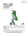
Owner’s Manual
8-inch Wheel
1/2 Horsepower (continuous duty)
2000 R.P.M. to 3450 R.P.M. (no load speed)
8-INCH
VARIABLE SPEED
BENCH GRINDER
Model No.
1010053
CAUTION:
FOR YOUR OWN SAFETY; Read
and follow all of the Safety and
Operating Instructions before
Operating this Bench Grinder
Customer Helpline
1-800-266-9079
Please have your Model No.
and Serial No. available.
37773.00 - 0513
TABLE OF CONTENTS
SECTION
PAGE
Contact Information........................................................................................................................................................2
Product Specifications...................................................................................................................................................2
Safety Instructions .........................................................................................................................................................3
Grounding Instructions..................................................................................................................................................5
Specific Safety Instructions for Bench Grinders ........................................................................................................6
Carton Contents .............................................................................................................................................................7
Assembly Instructions ...................................................................................................................................................8
Operating the Bench Grinder ......................................................................................................................................10
Maintenance ..................................................................................................................................................................13
Troubleshooting Guide ................................................................................................................................................13
Parts List .......................................................................................................................................................................14
Warranty.........................................................................................................................................................Back Cover
CONTACT INFORMATION
If you are unable to solve a problem using this manual, please contact us for advice.
Exclusive USA Agent: Colovos Company, 4444 West Ohio Street, Chicago, IL 60624, Tel.: (773) 533-4444
Repairs must be carried out only by qualified technical staff; and must follow the instructions and guidelines given in
this manual. Should technical assistance be required, contact Colovos Company at (773) 533-4444.
Colovos Company is not liable for, nor do they guarantee against, damage or operating malfunctions resulting from
alteration, abuse, and lack of maintenance or this product's use for other than its intended purpose. Failure to read and
follow the operating manual is not covered.
For repairs only use proper and suitable tools and parts purchased from an authorized agent.
PRODUCT SPECIFICATIONS
Motor
Continuous Duty HP
Volts
Amps
Hertz
RPM
Grinding Wheel Size
Grinding Wheel Grit
Lamp
Tool Rests
Eye Shield Assemblies
Spark Arrestors
Quench tray
WARNING
1/2
120
5.0
60
2000 R.P.M. to 3450 R.P.M.
(no load speed)
8" x 1", 5/8" bore
36 and 60
120V, 40 watt or less Track
Light Bulb, Type R20,
medium base or equivalent
(Not included)
To avoid electrical shock to yourself and damage to the
Bench Grinder, use proper circuit protection.
The Bench Grinder is factory wired for 120V, 60 Hz,
operation. Connect to a 120V, 15 amp branch circuit
and use a 15 amp time delay fuse or circuit breaker.
The electrical circuit cannot have any wire size less
than #14. To avoid shock or fire, replace power cord
immediately if it is damaged in any way.
Left and Right
Clear Lexan Left and Right
Left and Right
3.4" x 2.8" x 0.63"
2
SAFETY INSTRUCTIONS
8. DO NOT FORCE THE TOOL to perform an operation for which it was not designed. It will do a safer
and higher quality job by only performing operations
for which the tool was intended.
GENERAL SAFETY INSTRUCTIONS
Operating a Bench Grinder can be dangerous if safety
and common sense are ignored. The operator must be
familiar with the operation of the tool. Read this manual
to understand this Bench Grinder. DO NOT operate this
Bench Grinder if you do not fully understand the limitations of this tool. DO NOT modify this Bench Grinder in
any way.
9. WEAR PROPER CLOTHING. DO NOT wear loose
clothing, gloves, neckties, or jewelry. These items
can get caught in the machine during operations
and pull the operator into the moving parts. The
user must wear a protective cover on their hair, if
the hair is long, to prevent it from contacting any
moving parts.
BEFORE USING THE BENCH GRINDER
WARNING
10. CHILDPROOF THE WORKSHOP AREA by removing switch keys, unplugging tools from the electrical
recaptacles, and using padlocks.
To avoid serious injury and damage to the tool, read
and follow all of the Safety and Operating Instructions
before operating the Bench Grinder.
11. DO NOT use electrical tools in the presence of
flammable liquids or gasses.
WARNING
12. ALWAYS UNPLUG THE TOOL FROM THE ELECTRICAL RECEPTACLE when making adjustments,
changing parts or performing any maintenance.
1. Some dust created by using power tools contains
chemicals known to the State of California to cause
cancer, birth defects, or other reproductive harm.
Some examples of these chemicals are:
s Lead from lead-based paints.
s Crystalline silica from bricks, cement, and other
masonry products.
s Arsenic and chromium from chemically treated
lumber.
Your risk from these exposures varies, depending
on how often you do this type of work. To reduce
your exposure to these chemicals: work in a wellventilated area, and work with approved safety
equipment, such as those dust masks that are specially designed to filter out microscopic particles
13. KEEP PROTECTIVE GUARDS IN PLACE AND IN
WORKING ORDER.
14. AVOID ACCIDENTAL STARTING. Make sure that
the power switch is in the “OFF” position before
plugging in the power cord to the electrical
receptacle.
15. REMOVE ALL MAINTENANCE TOOLS from the
immediate area prior to turning “ON” the Bench
Grinder.
16. USE ONLY RECOMMENDED ACCESSORIES.
Use of incorrect or improper accessories could
cause serious injury to the operator and cause
damage to the tool. If in doubt, check the instruction
manual that comes with that particular accessory.
2. READ the entire Owner’s Manual. LEARN how to
use the tool for its intended applications.
3. GROUND ALL TOOLS. If the tool is supplied with a
3-prong plug, it must be plugged into a 3-contact
electrical receptacle. The 3rd prong is used to
ground the tool and provide protection against
accidental electric shock. DO NOT remove the 3rd
prong. See Grounding Instructions on page 4.
17. NEVER LEAVE A RUNNING TOOL UNATTENDED.
Turn the power switch to the “OFF” position. DO
NOT leave the tool until it has come to a complete
stop.
18. DO NOT STAND ON A TOOL. Serious injury could
result if the tool tips over or you accidentally contact
the tool.
4. AVOID A DANGEROUS WORKING ENVIRONMENT. DO NOT use electrical tools in a damp
environment or expose them to rain.
19. DO NOT store anything above or near the tool
where anyone might try to stand on the tool to
reach it.
5. DO NOT use electrical tools in the presence of
flammable liquids or gasses.
20. MAINTAIN YOUR BALANCE. DO NOT extend
yourself over the tool. Wear oil resistant rubbersoled
shoes. Keep floor clear of debris, grease, and wax.
6. ALWAYS keep the work area clean, well lit, and
organized. DO NOT work in an environment with
floor surfaces that are slippery from debris, grease,
and wax.
21. MAINTAIN TOOLS WITH CARE. Always keep tools
clean and in good working order. Keep all blades
and tool bits sharp.
7. KEEP VISITORS AND CHILDREN AWAY. DO NOT
permit people to be in the immediate work area,
especially when the electrical tool is operating.
3
22. EACH AND EVERY TIME, CHECK FOR DAMAGED
PARTS PRIOR TO USING THE TOOL. Carefully
check all guards to see that they operate properly,
are not damaged, and perform their intended functions. Check for alignment, binding or breaking of
moving parts. A guard or other part that is damaged
should be immediately repaired or replaced.
GUIDELINES FOR
EXTENSION CORDS
If you are using an extension cord outdoors, be sure
it is marked with the suffix “W-A” (“W” in Canada) to
indicate that it is acceptable for outdoor use.
23. CHILDPROOF THE WORKSHOP AREA by removing switch keys, unplugging tools from the electrical
receptacles, and using padlocks.
Be sure your extension cord is properly sized, and
in good electrical condition. Always replace a damaged
extension cord or have it repaired by a qualified person
before using it.
24. DO NOT OPERATE TOOL IF UNDER THE INFLUENCE OF DRUGS OR ALCOHOL.
Protect your extension cords from sharp objects,
excessive heat, and damp or wet areas.
25. SECURE ALL WORK. Use clamps or jigs to secure
the workpiece. This is safer than attempting to hold
the workpiece with your hands.
MINIMUM RECOMMENDED GAUGE FOR EXTENSION CORDS (AWG)
120 VOLT OPERATION ONLY
26. STAY ALERT, WATCH WHAT YOU ARE DOING,
AND USE COMMON SENSE WHEN OPERATING
A POWER TOOL. DO NOT USE A TOOL WHILE
TIRED OR UNDER THE INFLUENCE OF DRUGS,
ALCOHOL, OR MEDICATION. A moment of inattention while operating power tools may result in
serious personal injury.
27. ALWAYS WEAR A DUST MASK TO PREVENT
INHALING DANGEROUS DUST OR AIRBORNE
PARTICLES, including wood dust, crystalline silica
dust and asbestos dust. Direct particles away from
face and body. Always operate tool in well ventilated area and provide for proper dust removal. Use
dust collection system wherever possible. Exposure
to the dust may cause serious and permanent respiratory or other injury, including silicosis (a serious
lung disease), cancer, and death. Avoid breathing
the dust, and avoid prolonged contact with dust.
Allowing dust to get into your mouth or eyes, or lay
on your skin may promote absorption of harmful
material. Always use properly fitting NIOSH/OSHA
approved respiratory protection appropriate for the
dust exposure, and wash exposed areas with soap
and water.
28. USE A PROPER EXTENSION CORD IN GOOD
CONDITION. When using an extension cord, be
sure to use one heavy enough to carry the current
your product will draw. The table at right shows the
correct size to use depending on cord length and
nameplate amperage rating. If in doubt, use the
next heavier gauge. The smaller the gauge number,
the larger diameter of the extension cord. If in doubt
of the proper size of an extension cord, use a shorter and thicker cord. An undersized cord will cause a
drop in line voltage resulting in a loss of power and
overheating. USE ONLY A 3-WIRE EXTENSION
CORD THAT HAS A 3-PRONG GROUNDING
PLUG AND A 3-POLE RECEPTACLE THAT
ACCEPTS THE TOOL’S PLUG.
SAVE THESE INSTRUCTIONS.
4
25ƍ LONG
50ƍ LONG
100ƍ LONG
150ƍ LONG
0 to 6 Amps
18 AWG
16 AWG
16 AWG
14 AWG
6 to 10 Amps
18 AWG
16 AWG
14 AWG
12 AWG
10 to 12 Amps
16 AWG
16 AWG
14 AWG
12 AWG
GROUNDING INSTRUCTIONS
USE ONLY A 3-WIRE EXTENSION CORD THAT HAS
A 3-PRONG GROUNDING PLUG AND A 3-POLE
RECEPTACLE THAT ACCEPTS THE TOOL’S PLUG.
WARNING
THIS TOOL MUST BE GROUNDED WHILE IN USE
TO PROTECT THE OPERATOR FROM ELECTRIC
SHOCK.
REPLACE A DAMAGED OR WORN CORD IMMEDIATELY.
IN THE EVENT OF A MALFUNCTION OR BREAKDOWN, grounding provides the path of least resistance
for electric current and reduces the risk of electric
shock. This tool is equipped with an electric cord that
has an equipment grounding conductor and a grounding plug. The plug MUST be plugged into a matching
electrical receptacle that is properly installed and grounded in accordance with ALL local codes and ordinances.
This tool is intended for use on a circuit that has an
electrical receptacle as shown in FIGURE A. FIGURE A
shows a 3-wire electrical plug and electrical receptacle
that has a grounding conductor. If a properly grounded
electrical receptacle is not available, an adapter as
shown in FIGURE B can be used to temporarily connect this plug to a 2-contact ungrounded receptacle.
The adapter has a rigid lug extending from it that MUST
be connected to a permanent earth ground, such as a
properly grounded receptacle box. THIS ADAPTER IS
PROHIBITED IN CANADA.
DO NOT MODIFY THE PLUG PROVIDED. If it will not
fit the electrical receptacle, have the proper electrical
receptacle installed by a qualified electrician.
CAUTION: In all cases, make certain the electrical
receptacle in question is properly grounded. If you are
not sure have a certified electrician check the electrical
receptacle.
IMPROPER ELECTRICAL CONNECTION of the equipment grounding conductor can result in risk of electric
shock. The conductor with the green insulation (with or
without yellow stripes) is the equipment grounding
conductor. DO NOT connect the equipment grounding
conductor to a live terminal if repair or replacement of
the electric cord or plug is necessary.
WARNING
This Bench Grinder is for indoor use only. To avoid
serious injury, do not expose to rain or use in damp
locations.
CHECK with a qualified electrician or service personnel
if you do not completely understand the grounding
instructions, or if you are not sure the tool is properly
grounded.
120 Volt
120 Volt
Fig. A
Fig. B
grounding
adapter lug
3-prong
electrical receptacle
grounding
conductor
grounding
conductor
3-wire electrical cord
3-wire electrical cord
5
2-prong
electrical
receptacle
7. KEEP ALL WHEEL GUARDS IN PLACE. DO NOT
USE THE BENCH GRINDER WITH THE WHEEL
GUARDS REMOVED.
SPECIFIC SAFETY INSTRUCTIONS
FOR BENCH GRINDERS
The operation of any grinder can result in debris being
thrown into your eyes, which can result in severe eye
damage. ALWAYS WEAR EYE PROTECTION. Any
power tool can throw debris during operations, which
could cause severe and permanent eye damage.
Everyday eyeglasse are NOT safety glasses. ALWAYS
wear Safety Goggles (that comply with ANSI standard
Z87.1) when operating power tools.
8. KEEP THE TOOL RESTS FIRMLY TIGHTENED.
9. ALWAYS USE THE SUPPLIED WHEEL DRESSER
TO RESURFACE THE FACE OF THE GRINDING
WHEEL.
10. REMOVE ADJUSTING KEYS AND WRENCHES.
Form habit of checking to see that keys and adjusting wrenches are removed from tool before turning
it on.
Basic precautions should always be followed when
using your bench grinder. To reduce the risk of injury,
electrical shock, or fire, comply with the safety rules
listed below:
11. DIRECTION OF FEED. Feed work into a blade or
cutter against the direction of rotation of the blade
or cutter only.
1. ALWAYS USE THE EYE SHIELDS AND WHEEL
GUARDS provided with the grinder.
12. USE RIGHT TOOL. Don’t force tool or attachment
to do a job for which it was not designed.
2. REPLACE A CRACKED OR DAMAGED GRINDING WHEEL IMMEDIATELY. A damaged wheel can
discharge debris at a high velocity towards the
operator. Carefully handle the grinding wheels since
they are abrasive. Prior to replacing a grinding
wheel, check it for cracks. DO NOT remove the
blotter or label on both sides of the grinding wheel.
Tighten the spindle nut just enough to hold the
grinding wheel firmly to the Bench Grinder. Do not
over-tighten the nut. Excessive clamping force can
damage the grinding wheel. Only use the wheel
flanges provided with the grinder. When selecting a
replacement grinding wheel, verify that the grinding
wheel has a higher R.P.M. rating than the maximum
R.P.M. of the Bench Grinder.
13. DO NOT overtighten wheel nut.
14. ONLY use flanges furnished with the grinder.
15. FREQUENTLY clean grinding dust from beneath
grinder.
16. DO NOT FORCE THE TOOL to perform an operation for which it was not designed. It will do a safer
and higher quality job by only performing operations
for which the tool was intended.
17. ADDITIONAL INFORMATION regarding the safe and
proper operation of this product is available from:
s Power Tool Institute
1300 Summer Avenue
Cleveland, OH 44115-2851
www.powertoolinstitute.org
s National Safety Council
1121 Spring Lake Drive
Itasca, IL 60143-3201
s American National Standards Institute
25 West 43rd Street, 4th Floor
New York, NY 10036
www.ansi.org
s ANSI 01.1 Safety Requirements for
Woodworking Machines and the
U.S. Department of Labor regulations
www.osha.gov
3. THE DIAMETER OF THE GRINDING WHEELS
WILL DECREASE WITH USE. Adjust the tool rests
and spark arrestors to maintain a distance of 1/16”
from the wheel.
4. DO NOT STAND IN FRONT OF THE BENCH
GRINDER WHEN STARTING IT. Stand to one side
of the Bench Grinder and turn it “ON”. Wait at the
side for one minute until the grinder comes up to
full speed. There is always a possibility that debris
from a damaged grinding wheel may be discharged
towards the operator.
5. THE BENCH GRINDER WILL PRODUCE SPARKS
AND DEBRIS DURING GRINDING OPERATIONS.
Be sure that there are not any flammable materials
in the vicinity. Frequently clean grinding dust from
the back of the Bench Grinder.
18. SAVE THESE INSTRUCTIONS. Refer to them
frequently and use them to instruct others.
6. NEVER FORCE THE WORKPIECE AGAINST A
GRINDING WHEEL, especially if the wheel is cold.
Apply the workpiece slowly, allowing the grinding
wheel an opportunity to warm up. This will minimize
the chance of wheel breakage. DO NOT grind using
the sides of the grinding wheels. DO NOT apply
coolant directly to the grinding wheel.
6
CARTON CONTENTS
Fig. C
D
C
B
F
E
G
H
I
J
K
L
M
O
N
UNPACKING AND CHECKING
CONTENTS (Fig. C)
The following items are to be provided in the shipping
box:
This Bench Grinder will require a minimal amount of
assembly.
A. Grinder (not shown)
1. Remove parts from all of the cartons and lay them
on a clean work surface.
C. Eyeshield assembly, right
2. Remove any protective materials and coatings from
all of the parts and the bench grinder. The protective coatings can be removed by spraying WD-40
on them and wiping it off with a soft cloth. This may
need to be redone several times before all of the
protective coatings are removed completely.
E. Spark arrestor, left
B. Eyeshield assembly, left
D. Wheel dresser
F. Spark arrestor, right
G. Tool rest support, left
H. Tool rest support, right
I.
CAUTION: DO NOT use acetone, gasoline or
lacquer thinner to remove any protective coatings.
Carriage bolt M6 x 12 (2)
J. Pan head screws w/ washers M5 x 10 (4)
K. Flat washer M6 (4)
3. Compare the items to Figure C; verify that all items
are accounted for before discarding the shipping
box. If there are any missing parts, call Customer
Helpline 1-800-266-9079.
L. Tool rest, left
M. Tool rest, right
N. Eyeshield knob (2)
O. Tool rest knob (2)
WARNING
If any parts are missing, do not attempt to plug in the
power cord and turn “ON” the Bench Grinder. The
Bench Grinder can only be turned “ON” after all the
parts have been obtained and installed correctly.
7
ASSEMBLY INSTRUCTIONS
The Bench Grinder is provided with a left and right two
piece Tool Rest. Right Tool Rest has a flat, smooth
surface to lay your workpiece against. Left tool rest is
used to sharpen twist drill bits.
Fig. E
WARNING
I
1. DO NOT assemble the Bench Grinder until you are
sure the tool IS NOT plugged in.
2. DO NOT assemble the Bench Grinder until you are
sure the power switch is in the “OFF” position.
3. DO NOT assemble the Bench Grinder until you are
sure the grinding wheels are firmly tightened to the
Bench Grinder.
E
TOOL RESTS (Figs. D and E)
F
The Bench Grinder is provided with two different Tool
Rests assemblies. The Left Side Tool Rest is grooved
to accept drill bits. The Right Side Tool Rest is entirely flat.
1. Assemble the Tool Rest Supports (A) to the inside
surface of the Wheel Covers (B) with the flat and lock
washers (C) and knobs (D) as shown. See Figure D.
2. Assemble the Tool Rests (E) to the Supports (F)
with the flat washers (G) and Adjustment Knobs (H)
as shown. See Figure E.
3. Adjust each Tool Rest until its inside edge (I) is
1/16” from the grinding wheel. Firmly tighten the
knobs holding the supports. See Figure E.
Fig. D
B
D
A
C
8
G
SPARK ARRESTORS (Fig. F)
WORK LIGHT
1. Assemble the Spark Arrestors (A) to the front
surface of the Wheel Covers (B) with the flat
washers and pan head screws (C) as shown.
See Figure F.
The Bench Grinder is provided with a Flexible Work
Light to assist in visibility of the workpiece.
WARNING
2. Adjust each Spark Arrestor until the lower edge (D)
is 1/16" from the grinding wheel. Firmly tighten the
hex head screws. See Figure F.
To reduce the risk of fire, use a 120 volt, 40 Watt or less
Track Light Bulb, Type R20, medium base or equivalent
(not included). DO NOT use a light bulb that extends
past the end of the light housing.
Fig. F
CAUTION: The Flexible Work Light housing will remain
hot for a few minutes after turning it “OFF”. Avoid contact with housing until it is cool.
B
A
PERMANENT MOUNTING (Fig. I )
C
Use the mounting pads on the base of the grinder to
firmly attach grinder to a solid work surface (hardware
not included). See Figure I .
D
Fig. I
EYESHIELDS (Fig. H)
1. Assemble the eyeshield (C) to the Spark Arrestor
(A) inserting carriage head screw (B) through
the Spark Arrestor and the Eyeshield as shown.
See Figure H.
2. Assemble the flat washer (D) and Lock Knob (E)
to the carriage head screw and tighten until the
Eyeshield remains in the desired position.
See Figure H.
Fig. H
B
C
A
WARNING
D
To avoid serious injury, secure the Bench Grinder to a
solid work surface. If the Bench Grinder is not securely
mounted, it will have the ability to move or tip over
during grinding operations and possibly cause the
operator’s fingers to contact the grinding wheels.
E
9
OPERATING THE BENCH GRINDER
7. To use the Drill Bit Sharpening tool rest, lay the drill
bit flat in the “V” groove. Firmly hold on to the drill bit
shank. Slide the drill bit towards the grinding wheel
unit until it lightly touches. Keep the drill bit flat to
the plate and rotate the drill bit.
The Bench Grinder is designed for hand held grinding,
sharpening, and cleaning operations.
ALWAYS WEAR EYE PROTECTION! Hot sparks are
produced during grinding operations.
Sharpening and removal of metal can be done on the
right side of the Bench Grinder using the grinding
wheel. Cleaning of metal surfaces can be done using
the wire wheel on the left side of the Bench Grinder.
8. The operator may place the hot end of the workpiece into the water in the quench tray to cool it.
9.
GRINDING SPEED CHART
Low Speed 1745 RPM
High Speed 3450 RPM
Light Duty Operations
Heavy Duty/Normal Operations
Light Grinding
Heavy grinding
Sharpening
Stock Removal
Rust and paint removal
Deburring
Lowered grinding temperature
Buffing
After completing the grinding operations, turn “OFF”
the Bench Grinder by pushing down on the Power
Switch. CAUTION: It will take a few minutes for the
grinding wheels to come to a complete stop.
10. Turn the Variable Speed Switch counterclockwise to
return it to its slowest setting.
CAUTION: The Flexible Work Light housing will
remain hot for a few minutes after turning it “OFF”.
11. Avoid contact with housing until it is cool. Unplug
the Bench Grinder from the power source.
1. The Power Switch must be in the “OFF” position
and the Variable Speed Switch must be turned
to its slowest setting by being turned all the
way to the left until solid resistance is felt.
NOTE: To prevent unauthorized use of the Bench
Grinder, the power switch has a removable locking key.
With the power switch in the “OFF” position, pull the
locking key out. The Bench Grinder cannot be turned
“ON” with the key removed. Insert the locking key to
resume grinding operations.
2. Stand to the side of the Bench Grinder and plug in
the power cord to a suitable power source.
3. Remain to the side of the Bench Grinder and turn it
“ON” by moving the power switch to the up position.
4. Allow the grinding wheels to come up to a steady
speed for at least one minute. The R.P.M.’s of the
Bench Grinder can be now increased to the desired
speed for the particular grinding operation by rotating the Variable Speed Switch clockwise.
5. Adjust the eyeshields. Place the workpiece on the
appropriate tool rest for the desired operation.
6. Move the workpiece towards the grinding wheel
until it lightly touches. Move the workpiece back
and forth across the front surface of the grinding
wheel removing the amount of material desired.
WARNING
To avoid serious injury, never grind on the sides
of the grinding wheels.
10
USING THE WHEEL DRESSER
(Fig. J)
CHANGING THE GRINDING WHEEL
(Fig. K)
Fig. J
Fig. K
C
H
I
G
E
B
C
A
B
Due to normal wear, both wheels will need to be
replaced occasionally.
1. Turn the power switch OFF and unplug the power
cord from its power source.
The Wheel Dresser is to be used on the grinding
wheels. It will remove buildup up of material on the
grinding wheel, remove imperfections and make the
corners of the grinding wheel square. See Figure J.
2. Rotate the eyeshield up to access the tool rest.
3. Loosen the tool rest knob and rotate the tool rest
away from the grinding wheel.
DO NOT use the Wheel Dresser on the Wire Wheel.
4. Remove the Wheel Cover.
1. Adjust tool rest until it is in the flat horizontal
position as shown and 1/16" away from the
grinding wheel.
2. Turn “ON” the Bench Grinder. and then turn the
Variable Speed Switch clockwise until solid resistance is felt Let the grinding wheel come up to a
steady speed for one minute.
3. After the grinding wheel has gotten to a steady
speed, place the Wheel Dresser (B) flat on the
Tool Rest with the serrated wheels facing the
grinding wheel.
4. Firmly hold on to the handle of the Wheel Dresser.
5. Move the Wheel Dresser forward until the serrated
wheels make light contact with the grinding wheel
(C). After contact has been made, slide the Wheel
Dresser side to side across the Tool Rest to dress
the grinding wheel until the edge of the grinding
wheel is square and the surface is clean.
6. After the operator has completed dressing the
grinding wheel, turn “OFF” the Bench Grinder and
let the grinding wheel come to a complete stop.
7. Inspect the grinding wheel for any damage!
8. The grinding wheel may now be slightly smaller in
diameter after dressing. Readjust the tool rests and
spark arrestors to maintain a 1/16" clearance to the
grinding wheel.
11
5.
Push a wood wedge between the grinding wheel and
the guard. Then use a cresent wrench to remove the
arbor hex nut.
WIRE WHEEL or BUFFING WHEEL
(Fig. L)
Fig. L
6. NOTE: The left hand arbor hex nut is left hand
threaded and is loosened by rotating it clockwise.
The right hand arbor hex nut is right hand threaded
and is loosened by rotating it counter-clockwise.
B
A
7. Remove the Outer Wheel Flange (H) and then the
abrasive wheel (I) from the arbor shaft.
C
D
8. CAUTION: The new abrasive wheel to be put onto
the grinder must have a higher R.P.M. rating than
the grinder (3450 R.P.M.). The new abrasive wheel
must have the correct outer wheel diameter and
bore diameter as original wheels. The label on the
side of the abrasive wheel must stay on. DO NOT
remove this label.
E
E
9. Replace the abrasive wheel, outer wheel flange and
arbor hex nut. NOTE: The left hand arbor hex nut is
left hand threaded and is tightened by rotating it
counter-clockwise. The right hand arbor hex nut is
right hand threaded and is tightened by rotating it
clockwise.
A wire wheel or buffing wheel (A) can be used with your
grinder. Depending on the thickness of the wheel, you
will need to add one or more spacers to allow the arbor
hex nut to tighten correctly. These spacers are identical
to each other. Figure L shows the correct placement of
the spacers (B) and (C).
CAUTION: DO NOT OVER-TIGHTEN the arbor hex
nut as this may damage the abrasive wheel and
cause serious injury to the operator.
Note: One spacer (B) should always go onto the arbor
shaft first. The second spacer (C), if needed, will go on
next to the arbor hext nut (D) as shown. Always use the
wheel flanges (E) that came with the grinder for both
wire wheel and buffing wheels. See section CHANGING
THE GRINDING WHEEL for correct procedure of
changing wheels.
12
MAINTENANCE OF THE BENCH GRINDER
CAUTION: REPLACE the abrasive wheels if there is
amy damage at all. FAILURE to replace a damaged
wheel can cause serious injury to the operator.
WARNING
Turn the power switch “OFF” and unplug the power
cord from its power source prior to any maintenance.
CAUTION: DO NOT USE FLAMMABLE MATERIALS
to clean the Bench Grinder. A clean dry rag or brush is
all that is needed to remove dust and debris buildup.
LUBRICATION
The Bench Grinder has sealed lubricated bearings in
the motor housing that do not require any additional
lubrication from the operator.
WARNING
Repairs to the Bench Grinder should be performed by
trained personnel only. Unauthorized repairs or
replacement with non-factory parts could cause
serious injury to the operator and damage to the
Bench Grinder
CLEANING
With the Bench Grinder unplugged, rotate the abrasive
wheels slowly and inspect for any damage or trapped
shavings.
TROUBLESHOOTING
TO PREVENT INJURY TO YOURSELF or damage to the Bench Grinder, turn the switch to the “OFF” position and
unplug the power cord from the electrical receptacle before making any adjustments.
PROBLEM
LIKELY CAUSE(S)
SOLUTION
Motor does
not run
1.
2.
3.
4.
5.
1.
2.
3.
4.
5.
Motor does not
have full power
1. Incorrect line voltage
2. Capacitor has failed
3. Circuit board has failed
1. Have a qualified electrician check line for proper voltage
2 Replace capacitor
3. Replace circuit board
Motor runs hot
1. Motor is overloaded
2. Poor air circulation around motor
1. Reduce pressure on workpiece
2. Remove any blockage around motor
Motor stalls or
runs slow
1. Motor is overloaded
1. Reduce pressure on workpiece
2. Incorrect line voltage
3. Capacitor has failed
2. Have a qualified electrician check line for proper voltage
3. Replace capacitor
1.
2.
3.
4.
1.
2.
3.
4.
Fuse blows or
circuit breaker
trips
Machine not plugged in
Power switch in “OFF” position
Power cord is faulty
Fuse or circuit breaker are open
Circuit board has failed
Motor overloaded
Overloaded electrical circuit
Wrong fuse or circuit breaker
Undersized or excessive length of
extension cord, see manual
5. Grinding wheels are blocked
Plug power cord into electrical receptacle
Lift switch to “ON” position
Replace power cord
Overloaded electrical circuit
Replace circuit board
Reduce pressure on workpiece
Reduce the amount of items on circuit
Replace with correct fuse or circuit breaker
Use correct size
5. Unplug machine and remove obstruction
13
8-IN. BENCH GRINDER PARTS LIST
MODEL NO. 1010053
77
58
19
73
74
70
54
76
75
45
38
50
44
59
53
52
51
57
45
46
55
19
56
58
42
47
59
71
42
72
61
48
60
62
65
39
69
53 52
19
66
63
68
36
35
37
28
64
38
31
29
67
51
49
50
40
32
35
34
30 31
26
25
43
33
42
39
24
41
22
13
23
27
20
15
21
13
9
8
19
42
16 14
17
12
7
11 10
18
5
6
4
3
2
1
14
44
PARTS
MODEL
NO.
1010053
MODEL
NO.
M90083
8-IN. BENCH GRINDER PARTS LIST
WARNING
When servicing, use only Scheppach replacement parts. Use of any other parts may create a HAZARD or cause
product damage.
WARNING
Any attempt to repair or replace electrical parts on this Grinder may create a HAZARD unless repair is done by a
qualified service technician.
Ref.
No. Description
1
2
3
4
5
6
7
8
9
10
11
12
13
14
15
16
17
18
19
20
21
22
23
24
25
26
27
28
29
30
31
32
33
34
35
36
37
38
39
4-0.7 x 6mm Pan head screw w/washer
Coolant tray
Coolant tray plate
Circuit board
Tap screw
Cover
8-1.25 x 22mm Socket head bolt
Switch w/key
3-0.5 x 10mm Pan head screw
Switch guard
Knob
5-0.8 x 10mm Set screw
5-0.8 x 10mm Pan head screw
Spacer
Switch plate w/label
Potentiometer
Foot
5-0.8 x 16mm Pan head screw w/washer
8-1.25mm Hex nut
Capacitor
Base
4-0.7 x 16mm Pan head screw
Knob
4-0.7mm Hex nut
Cord plate
Strain Relief
Line cord
5-0.8 x 160mm Pan head screw
Left end bell
40mm Wavy washer
6203zz Ball bearing
5mm Flat washer
4-0.7 x 8mm Pan head screw w/washers
4mm Serrated washer
Grommet
Stator
Armature
5-0.8 x 48mm Pan head screw
5-0.8 x 51mm Carriage bolt
∆
N/A
*
Part
No.
*
35497.00
35498.00
35499.00
35500.00
35501.00
*
35502.00
*
35503.00
35504.00
*
*
35505.00
35506.00
35507.00
35508.00
*
*
35509.00
N/A
*
35510.00
*
35511.00
35512.00
35513.00
35514.00
N/A
31611.00
01901.00
*
*
*
*
N/A
N/A
*
35342.00
Ref.
No. Description
Qty.
40
41
42
43
44
45
46
47
48
49
50
51
52
53
54
55
56
57
58
59
60
61
62
63
64
65
66
67
68
69
70
71
72
73
74
75
76
77
∆
4
1
1
1
2
1
2
1
2
1
1
1
4
1
1
1
4
4
9
1
1
1
1
1
1
1
1
4
1
1
2
4
2
2
3
1
1
4
2
Not shown.
Not available as replacement part.
Standard hardware item available locally.
15
Right guard cover
16-2.0mm Hex nut
Flange
Grinding wheel 36#
Wire wheel spacer
5-0.8 x 10mm Pan head screw w/washer
Right guard w/label
Right toolrest support
Right toolrest
6mm Flat washer
Knob
5mm Flat washer (W)
5mm Lock washer
Knob
5-0.8 x 10mm Pan head screw w/washers
6-1.0 x 12mm Carriage bolt
Right Spark deflector
Right eyeshield assembly
6mm Flat washer
Knob
Right end bell
5-0.8 x 6mm Set screw
Feedback wheel
2.5 x 6mm screw
Sensor
5-0.8mm Hex nut
Cover
12-1.75mm Hex nut
12mm Flat washer
Work lamp w/label
Left guard cover
16-2.0mm Hex nut LH
Grinding wheel 60#
Left guard w/label
Left Spark deflector
Left toolrest support
Left toolrest
Left eyeshield assembly
Wheel dresser
Part
No.
35515.00
27338.00
35516.00
37775.00
35518.00
*
35519.00
35520.00
35521.00
*
35522.00
00227.00
*
35523.00
*
*
35524.00
35525.00
*
35526.00
N/A
*
35527.00
35528.00
35529.00
*
N/A
*
*
35530.00
35531.00
27339.00
35532.00
35533.00
35534.00
35535.00
35536.00
35537.00
35538.00
Qty.
1
1
4
1
1
6
1
1
1
2
2
2
2
2
4
2
1
1
2
2
1
1
1
2
1
4
1
1
1
1
1
1
1
1
1
1
1
1
1
LIMITED WARRANTY
ONE-YEAR LIMITED WARRANTY. MODELS COVERED IN THIS MANUAL, ARE WARRANTED TO THE ORIGINAL USER
AGAINST DEFECTS IN WORKMANSHIP OR MATERIALS UNDER NORMAL USE FOR ONE YEAR AFTER DATE OF
PURCHASE. ANY PART WHICH IS DETERMINED TO BE DEFECTIVE IN MATERIAL OR WORKMANSHIP AND RETURNED
SHIPPING COSTS PREPAID, WILL BE, AS THE EXCLUSIVE REMEDY, REPAIRED OR REPLACED AT OUR OPTION. FOR
LIMITED WARRANTY CLAIM PROCEDURES, SEE “PROMPT DISPOSITION” BELOW. THIS LIMITED WARRANTY GIVES
PURCHASERS SPECIFIC LEGAL RIGHTS WHICH VARY FROM JURISDICTION TO JURISDICTION.
LIMITATION OF LIABILITY. TO THE EXTENT ALLOWABLE UNDER APPLICABLE LAW, LIABILITY FOR CONSEQUENTIAL AND
INCIDENTAL DAMAGES IS EXPRESSLY DISCLAIMED. LIABILITY IN ALL EVENTS IS LIMITED TO AND SHALL NOT EXCEED
THE PURCHASE PRICE PAID.
WARRANTY DISCLAIMER. A DILIGENT EFFORT HAS BEEN MADE TO PROVIDE PRODUCT INFORMATION AND
ILLUSTRATE THE PRODUCTS IN THIS LITERATURE ACCURATELY; HOWEVER, SUCH INFORMATION AND ILLUSTRATIONS
ARE FOR THE SOLE PURPOSE OF IDENTIFICATION, AND DO NOT EXPRESS OR IMPLY A WARRANTY THAT THE
PRODUCTS ARE MERCHANTABLE, OR FIT FOR A PARTICULAR PURPOSE, OR THAT THE PRODUCTS WILL NECESSARILY
CONFORM TO THE ILLUSTRATIONS OR DESCRIPTIONS. EXCEPT AS PROVIDED BELOW, NO WARRANTY OR
AFFIRMATION OF FACT, EXPRESSED OR IMPLIED, OTHER THAN AS STATED IN THE “LIMITED WARRANTY” ABOVE IS
MADE OR AUTHORIZED.
Technical Advice and Recommendations, Disclaimer. Notwithstanding any past practice or dealings or trade custom, sales
shall not include the furnishing of technical advice or assistance or system design. No obligations or liability on account of any
unauthorized recommendations, opinions or advice as to the choice, installation or use of products shall be assumed for
SCHEPPACH MODELS.
Product Suitability. Many jurisdictions have codes and regulations governing sales, construction, installation, and/or use of
products for certain purposes, which may vary from those in neighboring areas. While attempts are made to assure that
Scheppach products comply with such codes, Colovos cannot guarantee FOR SCHEPPACH MODELS compliance, and cannot be
responsible for how the product is installed or used. Before purchase and use of a product, review the product applications, and all
applicable national and local codes and regulations, and be sure that the product, installation, and use will comply with them.
Certain aspects of disclaimers are not applicable to consumer products; e.g., (a) some jurisdictions do not allow the exclusion or
limitation of incidental or consequential damages, so the above limitation or exclusion may not apply to you; (b) also, some
jurisdictions do not allow a limitation on how long an implied warranty lasts, consequently the above limitation may not apply to
you; and (c) by law, during the period of this Limited Warranty, any implied warranties of implied merchantability or fitness for a
particular purpose applicable to consumer products purchased by consumers, may not be excluded or otherwise disclaimed.
Prompt Disposition. A good faith effort will be made for prompt correction or other adjustment with respect to any product which
proves to be defective within limited warranty. For any product believed to be defective within limited warranty, first write or call
dealer from whom the product was purchased. Dealer will give additional directions. If unable to resolve satisfactorily, write to the
address below, giving dealer’s name, address, date, and number of dealer’s invoice, and describing the nature of the defect. Title
and risk of loss pass to buyer on delivery to common carrier. If product was damaged in transit to you, file claim with carrier.
Contact Info:
Scheppach US Agent Colovos Company @ 4444 West Ohio Street, Chicago, IL 60624, Tel.: 1-773-533-4444.