1
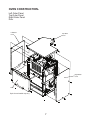
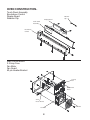
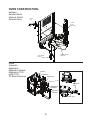
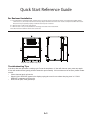
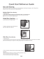
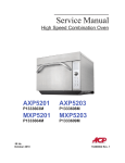
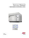
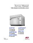
______________
Service Manual
Commercial Microwave Oven
Style of oven handle may vary
OC24
OC24BK
MOC24
AOC24
MOC6201J
60 Hz
June 2012
P2000301M
P2000302M
P2000305M
P2000306M
P2000312M
Accelerated Cooking Products
16400006
TABLE OF CONTENTS
IMPORTANT INFORMATION .....................................................................................................1
IMPORTANT SAFETY INFORMATION ................................................................................. 2-5
Oven Specifications ...............................................................................................................6
Oven Construction.............................................................................................................7-11
Oven Performance Test........................................................................................................12
Component Test Procedures .......................................................................................... 13-16
Troubleshooting Chart..................................................................................................... 17-18
Wiring Diagram.....................................................................................................................19
Schematic Diagram...............................................................................................................20
Appendix A
Quick Start Reference Guide.............................................................................................. A-1
- ii -
Important Information
Important Notices for Servicers and Consumers
ACP will not be responsible for personal injury or property damage from improper service procedures. Pride and
workmanship go into every product to provide our customers with quality products. It is possible, however, that during
its lifetime a product may require service. Products should be serviced only by a qualified service technician who is
familiar with the safety procedures required in the repair and who is equipped with the proper tools, parts, testing
instruments and the appropriate service information. IT IS THE TECHNICIANS RESPONSIBLITY TO REVIEW ALL
APPROPRIATE SERVICE INFORMATION BEFORE BEGINNING REPAIRS.
!
WARNING
To avoid risk of severe personal injury or death, disconnect power before working/servicing on appliance to avoid
electrical shock.
To locate an authorized servicer please contact:
ComServ Support Center
Web Site
WWW.ACPSOLUTIONS.COM
.......................
Telephone Number
1-866-426-2621 or 319-368-8195
E-Mail: [email protected]
Recognize Safety Symbols, Words, and Labels
!
DANGER
DANGER— Immediate hazards which WILL result in severe personal injury or death.
!
WARNING
WARNING— Hazards or unsafe practices which COULD result in severe personal injury or death.
!
CAUTION
CAUTION— Hazards or unsafe practices which COULD result in minor personal injury, product or property
damage.
1
Important Safety Information
!
WARNING
Read the following information to avoid possible exposure to microwave radiation:
The basic design of the Microwave Oven makes it an inherently safe device to both use and service.
However, there are some precautions which should be followed when servicing the microwave to maintain this
safety. These are as follows:
1. Always operate the unit from an adequately
grounded outlet. Do not operate on a two-wire
extension cord.
8. Do not for any reason defeat the interlock
switches there is not valid reason for this action
at any time; nor will it be condoned by ACP.
2. Before servicing the unit (if unit is operable) perform
the microwave leakage test.
9. IMPORTANT: Before returning a unit to a
customer, be sure to check for proper switch
interlock action.
3. The oven should never be operated if the door does
not fit properly against the seal, the hinges or hinge
bearings are damaged or broken; the choke is
damaged, (pieces missing, etc.); or any other
visible damage can be noted. Check the choke
area to ensure that this area is clean and free of all
foreign matter.
10. The Microwave Oven should never be
operated with any components removed and/or
bypassed or when any of the safety interlocks are
found to be defective, or when any of the seal
surfaces are defective, missing, or damaged.
11. All microwave ovens meet all requirements
of the radiation control for Health and Safety Act of
1968. Due to measurement uncertainties, the
maximum leakage for the field will be 4mw/cm2.
4. If the oven operates with the door open and
produces microwave energy, take the following
steps:
A. Tell the user not to operate the oven.
B. Contact ACP ComServ immediately.
12. To ensure that the unit does not emit excessive
microwave leakage and to meet the Department
of Health and Human Services guidelines, check
the oven for microwave leakage using a microwave
oven leakage meter that complies with US
Government CDRH / FDA / DHHS requirements
and or any other local government requirements.
The maximum leakage level allowed by ACP
2
is 4mw/cm .
5. Always have the oven disconnected when the outer
case is removed except when making the "live"
tests called for in the Service Manual. Do not
reach into the equipment area while the unit is
energized. Make all connections for the test and
check them for tightness before plugging the cord
into the outlet.
6. Always ground the capacitors on the magnetron
filter box with an insulated-handle screwdriver
before working in the high voltage area of the
equipment compartment. Some types of failures
will leave a charge in these capacitors and the
discharge could cause a reflex action which could
make you injure yourself.
13. If servicer encounters an emission reading over
4mw/cm 2, the servicer is to cease repair and
contact the ACP ComServ Department
immediately for further direction. ACP
will contact the proper Government
Agency upon verification of the test results.
7. Always remember that in the area of the
transformer there is HIGH VOLTAGE. When the
unit is operating keep this area clear and free of
anything which could possibly cause an arc or
ground, etc.
2
IMPORTANT SAFETY INSTRUCTIONS
Recognize this symbol as a SAFETY message
!
WARNING
When using electrical equipment, basic safety precautions should be followed to reduce the risk of burns,
electrical shock, fire, or injury to persons including the following.
1. READ all instructions before using equipment.
2. READ AND FOLLOW the specific
“PRECAUTIONS TO AVOID POSSIBLE
EXPOSURE TO EXCESSIVE MICROWAVE
ENERGY” on this page.
3. This equipment MUST BE GROUNDED. Connect
only to properly GROUNDED outlet. See “
GROUNDING / EARTHING INSTRUCTIONS” on
page 5.
4. Install or locate this equipment ONLY in
accordance with the installation instructions in
this manual.
5. Some products such as whole eggs and sealed containers—for example, closed glass jars—are
able to explode and SHOULD NOT be HEATED
in this oven.
6. Use this equipment ONLY for its intended use as
described in this manual. Do not use corrosive
chemicals or vapors in this equipment. This type
of oven is specifically designed to heat, cook,
or dry food. It is not designed for industrial or
laboratory use.
7. As with any equipment, CLOSE SUPERVISION
is necessary when used by CHILDREN.
9. DO NOT heat baby bottles in oven.
10. Baby food jars shall be open when heated and
contents stirred or shaken before consumption, in
order to avoid burns.
11 DO NOT operate this equipment if it has a
damaged cord or plug, if it is not working properly,
or if it has been damaged or dropped.
12. This equipment, including power cord, must be
serviced ONLY by qualified service personnel.
Special tools are required to service equipment.
Contact nearest authorized service facility for
examination, repair, or adjustment.
13. DO NOT cover or block louvers or other openings
on equipment.
14. DO NOT store this equipment outdoors. DO NOT
use this product near water – for example, near a
kitchen sink, in a wet basement, a swimming pool,
or a similar location.
15. DO NOT immerse cord or plug in water.
16. Keep cord AWAY from HEATED surfaces.
17. DO NOT let cord hang over edge of table or
counter.
18. For commercial use only.
8. See door cleaning instructions on page A-4 of
this owners manual.
PRECAUTIONS TO AVOID POSSIBLE
EXPOSURE TO EXCESSIVE MICROWAVE
ENERGY
A. DO NOT attempt to operate this oven with the door open since open door operation can result in harmful
exposure to microwave energy. It is important not to defeat or tamper with the safety interlocks.
B. DO NOT place any object between the oven front face and the door too allow soil or cleaner residue to
accumulate on sealing surfaces.
C. DO NOT operate the oven if it is damaged. It is particularly important that the oven door close properly and
that there is no damage to the:
1. door (bent)
2. hinges and latches (broken or loosened)
3. door seals and sealing surfaces.
D. The oven should not be adjusted or repaired by anyone except properly qualified service personnel.
SAVE THESE INSTRUCTIONS
3
IMPORTANT SAFETY INSTRUCTIONS
WARNING
WARNING
To avoid risk of fire in the oven cavity:
Liquids such as water, coffee, or tea are able to
be overheated beyond the boiling point without
appearing to be boiling due to surface tension of the
liquid. Visible bubbling or boiling when the container
is removed from the microwave oven is not always
present. THIS COULD RESULT IN VERY HOT
LIQUIDS SUDDENLY BOILING OVER WHEN A
SPOON OR OTHER UTENSIL IS INSERTED INTO
THE LIQUID. To reduce the risk of injury to persons:
a. DO NOT overcook food. Carefully attend oven
when paper, plastic, or other combustible
materials are placed inside the oven to facilitate
cooking.
b. Remove wire twist-ties from paper or plastic
bags before placing bag in oven.
c.If materials inside the oven ignite, keep oven
door CLOSED, turn oven off and disconnect
the power cord, or shut off power at the fuse or
circuit breaker panel.
i) Do not overheat the liquid.
ii) Stir the liquid both before and halfway through
heating it.
iii) Do not use straight-sided containers with narrow
necks.
iv) After heating, allow the container to stand in the
microwave oven for a short time before removing
the container.
v) Use extreme care when inserting a spoon or
other utensil into the container.
d. DO NOT use the cavity for storage. DO NOT
leave paper products, cooking utensils, or food
in the cavity when not in use.
!
CAUTION
To avoid personal injury or property damage, observe the following:
1. Do not deep fat fry in oven. Fat could overheat
and be hazardous to handle.
9. Never use paper, plastic, or other combustible
materials that are not intended for cooking.
2. Do not cook or reheat eggs in shell or with
an unbroken yolk using microwave energy.
Pressure may build up and erupt. Pierce yolk
with fork or knife before cooking.
10. When cooking with paper, plastic, or other
combustible materials, follow manufacturer’s
recommendations on product use.
11. Do not use paper towels which contain nylon or
other synthetic fibers. Heated synthetics could
melt and cause paper to ignite.
3. Pierce skin of potatoes, tomatoes, and similar
foods before cooking with microwave energy.
When skin is pierced, steam escapes evenly.
12. Do not heat sealed containers or plastic bags in
oven. Food or liquid could expand quickly and
cause container or bag to break. Pierce or open
container or bag before heating.
4. Do not operate equipment without load or food
in oven cavity.
5. Microwave popcorn should not be popped in
oven.
13. To avoid pacemaker malfunction, consult
physician or pacemaker manufacturer about
effects of microwave energy on pacemaker.
6. Do not use regular cooking thermometers in
oven. Most cooking thermometers contain
mercury and may cause an electrical arc,
malfunction, or damage to oven.
14. An authorized servicer MUST inspect equipment
annually. Record all inspections and repairs for
future use.
7. Do not use metal utensils in oven.
8. Do not use aluminum foil in oven
SAVE THESE INSTRUCTIONS
4
Important Safety Information
Grounding Instructions
! WARNING
! WARNING
To avoid risk of electrical shock, injury or death; make
sure these grounding instructions are followed.
PRECAUTIONS TO BE
OBSERVED BEFORE AND
DURING SERVICING TO
AVOID POSSIBLE EXPOSURE
TO EXCESSIVE MICROWAVE
ENERGY, OR ELECTRICAL
SHOCK. DISCONNECT
POWER TO OVEN.
! WARNING
Do not remove grounding prong when installing
grounded appliance in a home or business that does
not have three wire grounding receptacle, under no
condition is grounding prong to be cut off or removed.
It is the personal responsibility of the consumer to
contact a qualified electrician and have properly
grounded three prong wall receptacle installed in
accordance with appropriate electrical codes.
! WARNING
• Do not operate or allow oven to be operated with
door open.
• Make the following safety checks on all ovens to be
serviced before activating the magnetron or other
microwave source, and make repairs as necessary:
• Interlock operation
• Proper door closing
• Seal and sealing surfaces (arcing, wear, and
other damage)
• Damage to or loosening of hinges and latches
• Evidence of dropping or abuse
• Before turning on microwave power for any service
test or inspection within the microwave generating
compartments, check the magnetron, waveguide or
transmission line, and cavity for proper alignment,
integrity, and connections.
• Any failed or misadjusted components in the
interlock, monitor, door seal, and microwave
generation and transmission systems shall be
repaired, replaced or adjusted by procedures
described in this manual before oven is released to
the consumer.
• Check microwave leakage to verify compliance
with the federal performance standard should be
performed on each oven prior to release to the
consumer.
To avoid the risk of electrical shock or death, do not
alter the plug.
! WARNING
To avoid the risk of electrical shock or death, this
equipment must be grounded.
This equipment MUST be grounded. In the event of an
electrical short circuit, grounding reduces the risk of
electric shock by providing an escape wire for the
electric current. This oven is equipped with a cord
having a grounding wire with a grounding plug. The plug
must be plugged into an outlet that is properly installed
and grounded.
Consult a qualified electrician or servicer if grounding
instructions are not completely understood, or if doubt
exists as to whether the equipment is properly
grounded.
Do not use an extension cord. If the product power cord
is too short, have a qualified electrician install an appropriate
receptacle. This oven should be plugged into a
separate 50 or 60 hertz circuit with the electrical rating as
shown in the appropriate drawing. Models operate with a
208 or 230 supply voltage. When an oven is on a
circuit with other equipment, an increase in cooking
times may be required and fuses can be blown.
5
SPECIFICATIONS
Model
OC24 / OC24BK / MOC24 / AOC24/ MOC6201J
Configuration
Countertop or shelf
Control System
Touch, angled for easy viewing
Programmable Control Pads
10
Total Programmable Settings
100
Max. Cooking Time
10:00
Power Levels
11
Defrost
Yes
Time Entry Option
Yes
Microwave Distribution
Rotating antennas, top and bottom
Magnetrons
2
Display
LED
Stackable
Yes
Stage Cooking
Yes, 4
Door Opening
Automatic opening
Signal
Door opens automatically
Temp. Display
N/A
Exterior Dimensions
D**18 ⅝” (473) W 13 ⅝” (346) H 17 ¾” (451)
Cavity Dimensions
D 8 ¾” (222) W 11 ¾” (298) H 5 ⅜” (136)
Door Depth
n/a
Usable Cavity Space
.319 cubic ft. (.009m3)
Exterior Finish
Stainless steel
Interior Finish
Stainless steel
Power Consumption
3100 W
Power Output*
2400 W* Microwave (OC24, OC24BK, MOC24, AOC24)
Power Output*
2000 W* Microwave (MOC6201J)
Power Source
230V, 60 Hz, 20 A single phase
Plug Configuration / Cord
NEMA 6-20 63” (160cm) (OC24, OC24BK, MOC24, AOC24)
Plug Configuration / Cord
NEMA L6-20P 64" (183cm) (MOC6201J)
Frequency
2450 MHz
Product Weight
70 lbs. (32 kg.)
Ship weight (approx.)
73 lbs. (33 kg.)
Shipping Carton Size
H 20 ⅝” (524) W 17” (432) H 22” (559)
UPS Shippable
ISTA 3A approved small parcel
Measurements in ( ) and not
specified are millimeters
* IEC 705 Tested
6
OVEN CONSTRUCTIONLeft Outer Panel
Top Outer Panel
Right Outer Panel
Door
Left Outer
Panel
Top Outer
Panel
10
Right Outer
Panel
Door
Style of oven handle may vary.
7
OVEN CONSTRUCTIONTouch Panel Assembly
Escutcheon Control
Display Board
Retainer Clip
Display Board
Retainer
Clip
Touch Panel
Assembly
Escutcheon
Control
Main Control Board
2.5 Amp Fuse
Fan Motor
Fan Guard
40 pin Header Bracket
2.5 Amp
Fuse
Main Control
Board
40 Pin
Header Bracket
Fan Motor
8
Fan Guard
OVEN CONSTRUCTIONAntenna
Antenna Motor
Interlock Switch
Solenoid Assy
Antenna
(Top)
Interlock
Switch
(Right Side)
Solenoid Assembly
(Right Side)
Antenna Motor
(Bottom)
Diode
Capacitor
Magnetron
Magnetron Gasket
Magnetron TCO
Latch TCO
PC Board Harness
Diodes
Capacitors
Magnetrons
Magnetron
Gaskets
Magnetron
TCO
PC Board
Harness
Latch TCO
9
OVEN CONSTRUCTIONAntenna (Bottom)
Grease Shield
Ceramic Tray
Tray Support
Glide Strip
20 Amp Fuse
HV Transformer
Triac 40A
Control Transformer
20 Amp
Fuse
HV Transformer
Triac 40A
Control
Transformer
Grease
Shield
Ceramic
Tray
Glide
Strip
Antenna
(Bottom)
10
Tray Support
OVEN CONSTRUCTIONLower Back Panel
Cavity Exhaust Gasket
Cavity Exhaust Fan Motor
Cavity TCO
Cavity Fan Hood
Cavity Exhaust
Motor Gasket
Lower Back
Panel
Cavity Exhaust
Fan Motor
Cavity Fan
Hood
Cavity TCO
Hinge Assembly
Hinge Spring
Hinge Assembly
Hinge Spring
11
OVEN PERFORMANCE TEST
All Amana and Menumaster microwave oven power outputs are rated using the IEC705 standards. Using the
IEC705 test method requires precision measurements and equipment that is not practical to be performed in the
field. Using the test shown below will indicate if the oven performance is satisfactory.
Test equipment required:
•
•
1000 ml test container and thermometer.
Digital watch / watch with a second hand for use on ovens with electromechanical timers.
Important Notes:
•
•
•
Low line voltage will cause low temperature rise / power output.
Ovens must be on a dedicated circuit, properly grounded, and polarized. Other equipment on the same
circuit may cause a low temperature rise / power output.
This test and results are not a true IEC705 test procedures and are only intended to provide servicers with
an easy means of determining if the microwave oven cooking output is correct.
Procedure
1. Fill the test container to the 1000 ml line with cool tap water.
NOTE:
Water temperature should be approximately 60°F / 16°C
2. Using the thermometer, stir water for five to ten seconds; measure, and record the temperature (T1).
3. Place test container of water in the center of oven cavity and close door.
4. Heat the water for a 30-second full power cycle.
NOTE:
Use a digital watch or a watch with a second hand for ovens with electromechanical timers.
5. At end of the cycle, remove test container. Using the thermometer, stir water for five to ten seconds and record
temperature (T2).
6. Subtract the starting water temperature (T1) from the ending water temperature (T2) to obtain the temperature
rise (∆T).
7. If the temperature rise (∆T) meets or exceeds the minimum, the test is complete. If the temperature rise (∆T)
fails to meet the minimum temperature rise, test the line voltage to verify it is correct. Then repeat steps 1 - 6
making sure to change the water. If the temperature rise (∆T) fails to meet the minimum temperature rise again
the oven will require service.
Minimum Temperature Rise at Thirty (30) Seconds Run Time
∆T
(°F)
Cooking
Power Output
10..................1000
11..................1100
12..................1200
14..................1400
17..................1700
18..................1800
19..................1900
∆T
(°F)
Cooking
Power Output
∆T
(°C)
20..................2000
21..................2100
22..................2200
24..................2400
25..................2500
27..................2700
30..................3000
Cooking
Power Output
5 ...............1000
5.5 .............1100
6.5 .............1200
7.5 .............1400
9.5 .............1700
10 ..............1800
10.5 ...........1900
12
∆T
(°C)
Cooking
Power Output
11 ............2000
11.5 .........2100
12 ............2200
13 ............2400
13.5 .........2500
15 ............2700
16.5 .........3000
COMPONENT TESTING PROCEDURES
!
WARNING
To avoid risk of electrical shock, personal injury or death; disconnect power to oven and discharge capacitor
before servicing, unless testing requires power.
Illustration
Component
Magnetron TCO
Latch TCO
Cavity TCO
Diode
Testing
Disconnect all wires from TCO.
Measure resistance across terminals.
Magnetron TCO.....................................
Disconnect all wires from TCO.
Measure resistance across terminals.
Latch TCO .............................................
Disconnect all wires from TCO.
Measure resistance across terminals.
Cavity TCO............................................
Discharge Capacitor
Remove diode lead from capacitor and
connect ohmmeter.
Triac
Capacitor
Reverse leads for second test.
Resistance Check
Disconnect wires to triac
Measure resistance from:
MT1 to MT2
MT1 to Gate
MT2 to Gate
All terminals to ground
Voltage Check
Measure voltage from:
MT1 to Gate
MT1 to MT2
Discharge Capacitor
Remove wires from capacitor terminals
and connect ohmmeter, set on highest
resistance scale to terminals.
Also check between each terminal and
capacitor case.
Magnetron
Solenoid (Left, Right)
Results
Closed at 257ºF (125ºC) and
Opens at 300ºF (149ºC)
Opens at 230ºF (110ºC) and
Closes at 150ºF (66ºC)
Opens at 219ºF (104ºC)
Infinite resistance should be
measured in one direction and 50KΩ
or less in the opposite direction.
NOTE: Ohmmeter must contain a
battery of 6 volts minimum.
Caution – Do not operate oven with
wire to terminal MT2 removed.
Infinite
Approximately 60Ω
Infinite
Infinite
0.8 VAC when energized.
0 volts when gate energized or closed.
Line volts when gate not energized or
open.
Between Terminals: Meter should
momentarily deflect towards zero then
return to over 5 MΩ. If no deflection
occurs, or if continuous deflection
occurs, replace capacitor.
Terminal to Case: Infinite resistance
Discharge Capacitor
Between Terminals: Less than 1 Ω
Remove wires from magnetron and
connect ohmmeter to terminals. Also
check between each terminal and
ground.
Each terminal to ground measures
Infinite resistance.
Note: This test is not conclusive. If
oven does not heat and all other
components test good replace the
magnetron and retest.
Disconnect connector from solenoid
Measure resistance across coil.................. Approximately 6-11 Ω
Stirrer motor
Remove all wires from motor.
Measure resistance across terminals ....
13
Approximately 12K Ω
COMPONENT TESTING PROCEDURES
!
WARNING
To avoid risk of electrical shock, personal injury or death; disconnect power to oven and discharge capacitor
before servicing, unless testing requires power.
Illustration
Component
Transformer, HV
Main board
Testing
Discharge Capacitor
Remove all wires from terminals.
Measure resistance from:
230 to COM ..........................................
208 to COM ..........................................
230 to Ground
208 to Ground---------------------------------Terminal 5 to 6--------------------------------Terminal 7 to 8--------------------------------Terminal 4 to Ground------------------------See Main Board page 5
Results
Less than 1 Ω
Less than 1 Ω
Infinite
Infinite
Less than 1 Ω
Less than 1 Ω
Approximately 27 Ω
Left interlock switch assembly Disconnect wires to switch.
(Mechanical)
With door open measure resistance from:
Monitor – Terminals Rd- Bk..............
Primary – Terminals Bk - Brn ...........
Indicates continuity
Infinite Ω
With door closed measure resistance from:
Monitor – Terminals RD - BK ...........
Primary – Terminals BK - BN ........... Infinite Ω
Indicates continuity
Right interlock switch
assembly
(Mechanical)
After verifying or replacing the
assembly, re-connect wires to switch
and check operation of monitor circuit
before operating the oven.
Disconnect wires to switch.
With door open measure resistance from:
Monitor – Terminals RD- BK ............
Secondary – Terminals GY -RD.......
Indicates continuity
Infinite Ω
With door closed measure resistance from:
Monitor – Terminals RD - BK ...........
Secondary – Terminals GY - RD...... Infinite Ω
Indicates continuity
Transformer, control
Fan, cooling
After verifying or replacing the
assembly, re-connect wires to switch
and check operation of monitor circuit
before operating the oven.
(1) BU to (5) BR ----------------------------- --
Approximately 40 Ω or Line Voltage
(6) YL to (10) WH-------------------------------
Approximately 1 Ω or 28 VAC
Disconnect connector from fan.
Measure voltage at incoming leads ...........
Fan, exhaust
Approximately 24VDC
Disconnect connector from fan.
Measure voltage at incoming leads .......
14
Approximately 24VDC
COMPONENT TESTING PROCEDURES
!
WARNING
To avoid risk of electrical shock, personal injury or death; disconnect power to oven and discharge capacitor
before servicing, unless testing requires power.
Main. Board
Function
Input to main board
Left, Right Switch
Assembly
J4 Input from
Control
Transformer
Test Set-Up
Meter
Setting
Main Board
(Door Closed)
Volts
Main Board
Volts
Probe Placement
Main Board T-1
(Black wire)
Triac (Red wire)
J4-1 & J4-2
15
Results
Line voltage
28 VAC
COMPONENT TESTING PROCEDURES
!
WARNING
To avoid risk of electrical shock, personal injury or death; disconnect power to oven and discharge capacitor
before servicing, unless testing requires power.
Function
2.5 amp fuse
Note: If Fuse is blown
unit is non operational
Fuse is field
`replaceable.
208/230 Volt Relay
230 Volt Output
Test Set-Up
Remove fuse from
holder
Meter Setting
Ohms
Probe Placement
Measure resistance
across fuse
Results
Continuity
T4 to Blue wire at J1
Triac connection
Volts
T4 to Blue wire at
Triac Connection
208/230 Volt Relay
208 Volt Output
T3 to Blue wire at J1
Triac connection
Volts
T3 to Blue wire at
Triac Connection
J1 Triac Output
Connection
Orange wire to Red
wire
Volts
Power Relay
T3 to Blue wire at J1
Triac connection
Volts
Orange wire at Traic
Connection. Red wire
at Triac Connection
T3 to Blue wire at
Triac Connection
230 volts when
230 volts line
voltage present
208 volts when
208 volts line
voltage present
0.8 VAC when
Triac energized
T4 to Blue wire at J1
Triac Connection
Volts
Illustration
Component
Keypad
Test
Removal of touch panel is required to
perform test.
Continuity is indicated as 100 Ω and
below.
16
T4 to Blue wire at
Triac Connection
Pad
1
2
3
4
5
6
7
8
9
0
Start
Stop
Power Level
Time Entry
Trace
8 & 10
7 & 10
6 & 10
5 & 10
4 & 10
3 & 10
8&9
7&9
6&9
5&9
4&9
4&8
5&8
7&8
208 volts when
208 volts line
voltage present
230 volts when
230 volts line
voltage present
Results
Measurement
Continuity
Continuity
Continuity
Continuity
Continuity
Continuity
Continuity
Continuity
Continuity
Continuity
Continuity
Continuity
Continuity
Continuity
TROUBLESHOOTING CHART
Intial Power-Up
(Door Open)
Connect Power Cord
Open Door
No
1.No power applied to power cord.
2.Oven fuse open.
3.Main board control fuse.
4.Inoperative magnetron TCO.
5.Inoperative cavity TCO.
6.Broken or loose wire.
7.Inoperative control transformer.
8.Ribbon connector.
9.Inoperative display board.
No
1.Check interlock switches.
2.Check T1 connection.
3.Check J1-1 connection.
Close Door Then Open Door
Yes
Operation Normal
17
TROUBLESHOOTING CHART
Cook Condition
Place cup of water in oven and close door
No
Yes
Fans Run
1.Door not closed.
2.Inoperative switch assembly.
3.Broken or loose wire connection.
1. Bad fan.
2. Broken or loose wire connection.
No
Yes
Press Pad 1
No
Display starts counting down
Yes
1.Inoperative door latch.
2.Broken or loose wire connection.
No
Heats very slowly.
Note: Verify by performing power test.
Door opens at end of cycle
Yes
Water is heated
1.Inoperative touch panel.
2.Bad ribbon cable.
No
1.Inoperative high voltage transformer.
2.Inoperative capacitor.
3.Inoperative magnetron.
4.Inoperative diode.
5.Broken or loose wire connection.
No heat.
Yes
1.Inoperative triac.
2.Inoperative high voltage board.
3.Inoperative high voltage transformer.
4.Broken or loose wire connection.
Oven is operating properly
18
LEFT
PRIMARY
INTLK SW
LEFT
MONITOR
INTLK SW
RIGHT
SECONDARY
INTLK SW
RIGHT
MONITOR
INTLK SW
COM
COM
COM
COM
NO
NC
NO
NC
NO
NC
NO
NC
BR
GY
BK
RD
BR
BK
RD
RD
BK
POWER
CORD
(20A)
FUSE
BK
GN
BK
WH
D
C
B
A
TERM
BLOCK
WH
CONTROL
XFMR
GY
BR
DISPLAY
BOARD
1
5
BU
BU
6
10
YL
PK
TOP
ANTENNA
MOTOR
WH
OR
BOTTOM
ANTENNA
MOTOR
T4
RD
RD
OR
VT
19
J1
J2
J2
BK
T1
OR
J1
RD OR
MAIN BOARD
T2
OR
TRIAC
1 2 G
KEYPAD SWITCH
T3
RD
BU
BU
BU
WH
J3
POWER
XFMR
EXHAUST
FAN
RD
RD BU
J7
(2.5A)
YL
J4
GY
BU
COM
5
VT
VT
208
HV
4
6
P2
8
OVEN
GY TCO
YL
YL
BK
BK
RD
COOLING FAN
SHIELDED
CABLE
230
PK
7
BK
BK
VT
RD
RD
WH
WH
P1
DATA KEY BOARD
(NOT AVAILABLE ON ALL MODELS)
GY
RECTIFIER
BOTTOM
CAPACITOR
GY
YL
BOTTOM
MAGNETRON
GY
TOP
MAGNETRON
VT
YL
RD
F
FA
BK
YL
GY
YL
VT
RECTIFIER
TOP
CAPACITOR
MAG TCO
FA
F
LATCH TCO
BK
MAG TCO
RED RD
PINK PK
ORANGE OR
YELLOW YL
GREEN GN
BLUE BU
VIOLET VT
BLACK BK
BROWN BR
GRAY GY
WHITE WH
COLOR CODE
WIRE CODE
HIGH VOLTAGE
LOW VOLTAGE
WIRING DIAGRAM
PART NO. 20016102
WH
VT
WH
VT
BU
BU
BU
BU
RIGHT
SOLENOID
LEFT
SOLENOID
Wiring Diagram - OC24 / OC24BK / MOC24 / AOC24 / MOC6201J
Schematic Diagram - OC24 / OC24BK / MOC24 / AOC24 / MOC6201J
20
Appendix A
A-1
Quick Start Reference Guide
Refer to Product Safety Manual for Safety Statements
So...how do I use it?
Preprogrammed Pads
To cook food using preprogrammed
cooking sequences.
1.
2.
3.
4.
Place food in oven. Close door.
Press desired pad.
Oven begins to cook.
At end of cooking cycle oven
door opens
Manual Operation
To cook food using a specific entered time and power level.
1. Place food in oven. Close door.
2. Press TIME ENTRY pad and enter cooking time.
3. Press POWER LEVEL pad to program microwave power level if less than
100% is desired.
• For a lower microwave power, press pads 1 (for 10%),
through 9 (for 90%), or 0 for no microwave energy.
4. Press START pad.
5. At end of cooking cycle oven door opens.
Programming Items
1.
2.
3.
4.
Press and hold pad 1 for approximately 5 seconds with the door open.
Press pad to be reprogrammed.
Enter cooking time by using the number pads.
Press POWER LEVEL pad to program microwave power level if less than
100% is desired.
• For a lower microwave power, press pads 1 (for 10%),
through 9 (for 90%), or 0 for no microwave energy.
NOTE: Press POWER LEVEL pad twice to return to 100% microwave power.
5. Press TIME ENTRY pad to add up to three additional cooking stages.
• Total cooking time cannot exceed 5 minutes.
• Enter cook time and power level as in steps 4 and 5.
6. Press START pad to set new programming changes to the pad.
NOTE: To discard changes, press STOP pad or close oven door.
Factory Settings
Pad
Seconds
1
5
2
10
3
15
4
20
5
25
6
30
7
35
8
40
9
45
0
60
Installation
•
•
•
•
•
•
Do not install oven next to or above source of heat, such as pizza oven
or deep fat fryer. This could cause microwave oven to operate improperly
and could shorten life of electrical parts.
Do not block or obstruct oven air inlet above door. Install oven on level countertop surface.
Not recommended for built-in installations.
Outlet should be located so that plug is accessible when oven is in place.
A safety strap is attached to the side of the oven. This is to be used to
secure two ovens together (back to back) on a shelf.
Style of oven handle may vary.
A-2
Quick Start Reference Guide
For Enclosed Installation
A—For North America (UL/CSA) models, allow at least 2” (5.1cm) of clearance around top of oven. For International (50Hz) models,
allow at least 7 “ (17.78 cm) of clearance around top. Proper air flow around oven cools electrical components. With restricted air
flow, oven may not operate properly and life of electrical parts is reduced.
B—Allow at least 1” (2.54 cm) on sides of oven.
C—Allow at least 1 1/4” (3.18 cm) between air discharge on back of oven and back wall.
Note: Back to back installation allows correct clearance.
Oven Clearances
A
B
B
C
Style of oven handle may vary.
Troubleshooting Tips
If the door does not open after a cooking cycle. Press the stop button. If door still does not open, press stop again.
If door still remains closed, gently pull door forward to open manually. If this continues to be an issue, please contact
service.
• If door does not latch, call service.
• Should “CALL SERVICE” appear in the display unplug the oven for one minute then plug oven in. If “CALL
SERVICE” reappears call for service.
• Door slow to open, clean glide strips.
A-3
Quick Start Reference Guide
Care and Cleaning
Clean interior and exterior of microwave oven with mild detergent and damp soft sponge or cloth. Wring cloth or
sponge to remove excess water before wiping equipment.
Splatter Shield (Clean Monthly)
1. Unplug the oven.
2. Place fingers behind the shield, pull forward and then down. Do not bend antenna.
3. Clean soil from shield with damp cloth or clean with mild detergent and water.
Note: Do not run oven without splatter shield.
Interior Door (Clean Daily)
1. To clean interior door, gently pull out on door
until door opens at a 90-degree angle.
2. Wipe the underside of door and inside door
arms with a damp cloth. Wipe dry.
Style of oven handle may vary.
Glide Strips (Clean Monthly)
Style of oven handle may vary.
1. Unplug the oven.
2. Clean in between door arms and side of cavity with a cloth (Do not use paper towels) on the end of a non metallic
spatula with mild detergent or degreaser, cleaning the glide strips on both sides of the cavity.
3. Place door back in ready position by gently pushing downward.
Important:
-Do not use abrasive cleaners or cleaners containing ammonia or citrus.
-Never pour water into microwave oven bottom.
-Do not use water pressure type cleaning systems.
A-4
Quick Start Reference Guide
Changing user options
Options such as single or double pad programming and beep volume can be changed to suit individual preferences.
To change options:
1. Press and hold pad 2 for approximately 5 seconds with door open.
2. Option appears in display.
• Oven is now in options mode.
3. Press number pad that controls option to be changed.
• See table below for options.
• Current option will display.
4. Press number pad again to change the option.
• Each time pad is pressed, option will change.
• Match code displayed with code for desired option.
• Changes take affect after START pad is pressed.
• To change additional options, repeat steps 3 and 4. 5. Press START pad to return to Options. Open and close oven door or press STOP to exit.
Numbered Pads
Display
Options (Factory Settings in Bold)
OP:10
OP:11
OP:12
OP:13
OP:14
OP:15
OP:16
3 second continuous beep.
5 second beeps once.
Continuous beep until done disappears.
Repeating 5 beeps bursts untildoor is opened.
Continuous beep until stop pad is pressed or door is cycled.
Repeating 5 beeps burst until stop pad is pressed or door is cycled.
No beep.
2
Speaker Volume
OP:20
OP:21
OP:22
OP:23
Eliminates beep.
Sets volume to low.
Sets volume to medium.
Sets volume to high.
3
Key Beep
OP:30
OP:31
Prevents beep when pad is pressed.
Allows beep when pad is pressed.
4
Keyboard Enable
Window
OP:40
OP:41
OP:42
15 seconds after oven door is closed, keyboard disabled.
30 seconds after oven door is closed, keyboard disabled.
1 minute after oven door is closed, keyboard disabled.
OP:43
2 minutes after oven door is closed, keyboard disabled.
OP:50
OP:51
OP:52
OP:53
OP:55
OP:56
OP:57
OP:58
OP:59
10 seconds
20 seconds
30 seconds
40 seconds
60 seconds
1 minute 10 seconds
1 minute 20 seconds
1 minute 30 seconds
1 minute 40 seconds
6
OP:60
Pressing stop clears information, opens door.
Stop during
cooking cycle
OP:61
OP:62
Pressing stop pauses oven with door closed.
Pressing stop pauses oven with door open.
1
End of Cycle Beep
5
End of Cycle Message
Time
7
OP:70
Allows 5 minutes of heating time.
OP:71
Allows 10 minutes of heating time.
8
Time Entry
OP:80
OP:81
Allows use of preprogrammed pads only.
Allows use of manual time entry and preprogrammed pads.
9
Double Digit Operation
OP:90
OP:91
Allows 10 (0-9) preprogrammed pads.
Allows 100 (00-99) preprogrammed pads.
0
OP:00
Disables ON-THE-FLY Cooking.
ON-THE-FLY Cooking
OP:01
Allows ON-THE-FLY Cooking.
Maximum Cook Time Entry
A-5
60 Hz Commercial Microwave
June 2012
16400006