1
Installation Guide
for Clients
Microsoft Network Client
®
Version 2.2
Microsoft Corporation
Information in this document is subject to change without notice. Companies, names, and data used in
examples herein are fictitious unless otherwise noted. No part of this document may be reproduced or
transmitted in any form or by any means, electronic or mechanical, for any purpose, without the
express written permission of Microsoft Corporation.
©1992-1993
Microsoft Corporation. All rights reserved.
Microsoft, MS, and MS-DOS are registered trademarks and Windows and Windows NT are
trademarks of Microsoft Corporation in the United States of America and other countries.
U.S. Patent No. 4955066
3Com and EtherLink are registered trademarks of 3Com Corporation.
Compaq is a registered trademark of Compaq Computer Corporation.
DCA is a registered trademark of Digital Communications Associates, Inc.
Everex is a trademark of Everex Systems, Inc.
DynaComm is a registered trademark of Future Soft Engineering, Inc.
Ethertwist and Hewlett-Packard are registered trademarks of Hewlett-Packard Company.
Intel is a registered trademark and Ether Express and Token Express are trademarks of
Intel Corporation.
IBM, Operating System/2, and OS/2 are registered trademarks of International Business
Machines Corporation.
Microcom is a registered trademark of Microcom Systems, Inc.
Novell and NetWare are registered trademarks of Novell, Inc.
Stacker is a registered trademark of STAC Electronics.
SMC is a registered trademark of Standard Microsystems Corporation.
Tulip is a registered trademark of Tulip Computers, International, B.V.
Ungermann-Bass is a registered trademark of Ungermann-Bass, Inc.
Rumba is a registered trademark and Wall Data is a trademark of Wall Data Incorporated.
Western Digital is a trademark of Western Digital Corporation.
XNS is a trademark of Xerox Corporation.
Document No. CSE52703-0693
Printed in the United States of America.
iii
Contents
Before You Begin . . . . . . . . . . . . . . . . . . . . . . . . . . . . . . . . . . . . . . . . . . . . . . . . . .
How to Use This Manual. . . . . . . . . . . . . . . . . . . . . . . . . . . . . . . . . . . . . . . . . . .
Documentation Conventions. . . . . . . . . . . . . . . . . . . . . . . . . . . . . . . . . . . . . . . .
Finding Further Information . . . . . . . . . . . . . . . . . . . . . . . . . . . . . . . . . . . . . . . .
1
2
3
4
Part 1 Overview, Preparation, and Planning
Chapter 1 Introduction . . . . . . . . . . . . . . . . . . . . . . . . . . . . . . . . . . . . . . . . . . . . 7
Using the Setup Program’s Interface . . . . . . . . . . . . . . . . . . . . . . . . . . . . . . . . 7
Scrolling . . . . . . . . . . . . . . . . . . . . . . . . . . . . . . . . . . . . . . . . . . . . . . . . . . . . . . . 7
Using the Keyboard . . . . . . . . . . . . . . . . . . . . . . . . . . . . . . . . . . . . . . . . . . . . . 8
Online Help . . . . . . . . . . . . . . . . . . . . . . . . . . . . . . . . . . . . . . . . . . . . . . . . . . . . . . . 9
System Requirements . . . . . . . . . . . . . . . . . . . . . . . . . . . . . . . . . . . . . . . . . . . . . 10
Before Installing . . . . . . . . . . . . . . . . . . . . . . . . . . . . . . . . . . . . . . . . . . . . . . . . . . 11
Chapter 2 Planning for Installation and Configuration . . . . . . . . . . . . . . .
Configuration Planning Forms . . . . . . . . . . . . . . . . . . . . . . . . . . . . . . . . . . . . .
Planning for LAN Manager Installations on MS-DOS Computers . . . .
Computer Configuration. . . . . . . . . . . . . . . . . . . . . . . . . . . . . . . . . . . . . . . .
Fundamental Installation Decisions . . . . . . . . . . . . . . . . . . . . . . . . . . . . . .
Network Adapter Drivers and Protocols . . . . . . . . . . . . . . . . . . . . . . . . .
TCP/IP Settings . . . . . . . . . . . . . . . . . . . . . . . . . . . . . . . . . . . . . . . . . . . . .
Workstation Settings . . . . . . . . . . . . . . . . . . . . . . . . . . . . . . . . . . . . . . . . . . .
Running LAN Manager with the Windows Operating System . . . . .
Using Stacker with LAN Manager . . . . . . . . . . . . . . . . . . . . . . . . . . . . . .
MS-DOS Memory Management . . . . . . . . . . . . . . . . . . . . . . . . . . . . . . . .
Planning for LAN Manager Installations on OS/2 Computers . . . . . . . .
Computer Configuration. . . . . . . . . . . . . . . . . . . . . . . . . . . . . . . . . . . . . . . .
Network Adapter Drivers and Protocols . . . . . . . . . . . . . . . . . . . . . . . . .
TCP/IP Settings . . . . . . . . . . . . . . . . . . . . . . . . . . . . . . . . . . . . . . . . . . . . .
Workstation Settings . . . . . . . . . . . . . . . . . . . . . . . . . . . . . . . . . . . . . . . . . . .
Services Parameters . . . . . . . . . . . . . . . . . . . . . . . . . . . . . . . . . . . . . . . . . . . .
13
13
20
20
21
22
23
24
25
26
26
29
29
30
31
32
34
iv
Contents
Part 2 Installing LAN Manager Workstation Software
Chapter 3 Installing LAN Manager on MS-DOS Workstations . . . . . . . . . 37
Installing LAN Manager Software on an MS-DOS Workstation . . . . . . 38
After Installing an MS-DOS Workstation. . . . . . . . . . . . . . . . . . . . . . . . . . . 39
Setting Up the Path on an MS-DOS Workstation. . . . . . . . . . . . . . . . . 40
Installing a Mouse Driver . . . . . . . . . . . . . . . . . . . . . . . . . . . . . . . . . . . . . . . 40
Running Netbind Before Loading Applications in MS-DOS . . . . . . . 41
Using the Prtsc Utility . . . . . . . . . . . . . . . . . . . . . . . . . . . . . . . . . . . . . . . . . . 41
Sending Messages on a Computer With Multiple Network Adapters42
Modifying the Microsoft Windows SETUP.INF File. . . . . . . . . . . . . . 43
Chapter 4 Installing LAN Manager on OS/2 Workstations . . . . . . . . . . . . 45
Installing an OS/2 Workstation . . . . . . . . . . . . . . . . . . . . . . . . . . . . . . . . . . . . 46
After Installing an OS/2 Workstation . . . . . . . . . . . . . . . . . . . . . . . . . . . . . . . 47
Chapter 5 Setup Screen Basics . . . . . . . . . . . . . . . . . . . . . . . . . . . . . . . . . . .
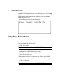
Starting the Setup Screen. . . . . . . . . . . . . . . . . . . . . . . . . . . . . . . . . . . . . . . . . .
Using Setup Screen Menus . . . . . . . . . . . . . . . . . . . . . . . . . . . . . . . . . . . . . . . .
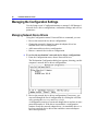
Saving Configuration Changes . . . . . . . . . . . . . . . . . . . . . . . . . . . . . . . . . . . . .
Changing Your Configuration With Setup . . . . . . . . . . . . . . . . . . . . . . .
Exiting the Setup Screen . . . . . . . . . . . . . . . . . . . . . . . . . . . . . . . . . . . . . . . . . .
49
49
50
52
52
53
Part 3 Managing Your LAN Manager Configuration
Chapter 6 Managing an MS-DOS Workstation . . . . . . . . . . . . . . . . . . . .
Managing the Configuration Settings . . . . . . . . . . . . . . . . . . . . . . . . . . . . . . .
Managing Network Device Drivers. . . . . . . . . . . . . . . . . . . . . . . . . . . . . .
Managing Workstation Settings . . . . . . . . . . . . . . . . . . . . . . . . . . . . . . . . .
Installing or Managing Connectivity Services . . . . . . . . . . . . . . . . . . . . . . .
Removing LAN Manager. . . . . . . . . . . . . . . . . . . . . . . . . . . . . . . . . . . . . . . . . .
57
58
58
71
75
76
Chapter 7 Managing an OS/2 Workstation . . . . . . . . . . . . . . . . . . . . . . . . . .
Managing the Configuration Settings . . . . . . . . . . . . . . . . . . . . . . . . . . . . . . .
Managing Network Device Drivers. . . . . . . . . . . . . . . . . . . . . . . . . . . . . .
Managing Workstation Settings . . . . . . . . . . . . . . . . . . . . . . . . . . . . . . . . .
Managing Services Parameters . . . . . . . . . . . . . . . . . . . . . . . . . . . . . . . . . .
Installing or Managing Connectivity Services . . . . . . . . . . . . . . . . . . . . . . .
79
80
80
92
94
95
Contents
v
Detaching, Attaching, or Removing LAN Manager. . . . . . . . . . . . . . . . . .
Detaching LAN Manager . . . . . . . . . . . . . . . . . . . . . . . . . . . . . . . . . . . . . . .
Attaching LAN Manager . . . . . . . . . . . . . . . . . . . . . . . . . . . . . . . . . . . . . . .
Removing LAN Manager . . . . . . . . . . . . . . . . . . . . . . . . . . . . . . . . . . . . . . .
96
96
97
98
Part 4 Network Device Drivers
Chapter 8 About Network Device Drivers . . . . . . . . . . . . . . . . . . . . . . . . .
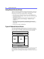
Using Network Device Drivers . . . . . . . . . . . . . . . . . . . . . . . . . . . . . . . . . . .
Types of Network Device Drivers . . . . . . . . . . . . . . . . . . . . . . . . . . . . . . . .
Protocol Manager . . . . . . . . . . . . . . . . . . . . . . . . . . . . . . . . . . . . . . . . . . . . . . .
The NetBIOS Interface . . . . . . . . . . . . . . . . . . . . . . . . . . . . . . . . . . . . . . . . . .
NetBIOS 3.0 and the CONFIG.SYS File . . . . . . . . . . . . . . . . . . . . . . .
NetBIOS 3.0 and the LANMAN.INI File . . . . . . . . . . . . . . . . . . . . . . .
Network Device Driver Configuration Files. . . . . . . . . . . . . . . . . . . . . . . .
The CONFIG.SYS File. . . . . . . . . . . . . . . . . . . . . . . . . . . . . . . . . . . . . . . .
The AUTOEXEC.BAT or STARTUP.CMD File . . . . . . . . . . . . . . .
The PROTOCOL.INI File . . . . . . . . . . . . . . . . . . . . . . . . . . . . . . . . . . . . .
The LANMAN.INI File . . . . . . . . . . . . . . . . . . . . . . . . . . . . . . . . . . . . . . .
LAN Manager for OS/2 . . . . . . . . . . . . . . . . . . . . . . . . . . . . . . . . . . . .
The Driver-Information Files . . . . . . . . . . . . . . . . . . . . . . . . . . . . . . . . . .
NIF Files . . . . . . . . . . . . . . . . . . . . . . . . . . . . . . . . . . . . . . . . . . . . . . . . . .
XIF Files . . . . . . . . . . . . . . . . . . . . . . . . . . . . . . . . . . . . . . . . . . . . . . . . . .
The PROTOCOL.INI File . . . . . . . . . . . . . . . . . . . . . . . . . . . . . . . . . .
Configuration Examples . . . . . . . . . . . . . . . . . . . . . . . . . . . . . . . . . . . . . . . . . .
Example 1 . . . . . . . . . . . . . . . . . . . . . . . . . . . . . . . . . . . . . . . . . . . . . . . . .
Example 2 . . . . . . . . . . . . . . . . . . . . . . . . . . . . . . . . . . . . . . . . . . . . . . . . .
Example 3 . . . . . . . . . . . . . . . . . . . . . . . . . . . . . . . . . . . . . . . . . . . . . . . . .
Example 4 . . . . . . . . . . . . . . . . . . . . . . . . . . . . . . . . . . . . . . . . . . . . . . . . .
Example 5 . . . . . . . . . . . . . . . . . . . . . . . . . . . . . . . . . . . . . . . . . . . . . . . . .
103
104
104
107
107
108
108
109
110
111
112
113
114
115
115
117
119
120
120
122
124
126
128
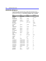
Chapter 9 Network Device Driver Options . . . . . . . . . . . . . . . . . . . . . . . . .
Protocol Drivers . . . . . . . . . . . . . . . . . . . . . . . . . . . . . . . . . . . . . . . . . . . . . . . . .
Microsoft NetBEUI 2.1 . . . . . . . . . . . . . . . . . . . . . . . . . . . . . . . . . . . . . . .
Media-Access Control Drivers. . . . . . . . . . . . . . . . . . . . . . . . . . . . . . . . . . . .
131
131
132
140
vi
Contents
3Com EtherLink . . . . . . . . . . . . . . . . . . . . . . . . . . . . . . . . . . . . . . . . . . . . . .
3Com EtherLink II . . . . . . . . . . . . . . . . . . . . . . . . . . . . . . . . . . . . . . . . . . . .
3Com EtherLink III Family . . . . . . . . . . . . . . . . . . . . . . . . . . . . . . . . . . . .
3Com EtherLink 16 . . . . . . . . . . . . . . . . . . . . . . . . . . . . . . . . . . . . . . . . . . .
3Com EtherLink Plus . . . . . . . . . . . . . . . . . . . . . . . . . . . . . . . . . . . . . . . . .
3Com EtherLink/MC . . . . . . . . . . . . . . . . . . . . . . . . . . . . . . . . . . . . . . . . . .
3Com EtherLink/MC32 . . . . . . . . . . . . . . . . . . . . . . . . . . . . . . . . . . . . . . .
3Com TokenLink . . . . . . . . . . . . . . . . . . . . . . . . . . . . . . . . . . . . . . . . . . . . .
Accton Technology EtherCoax - 16N . . . . . . . . . . . . . . . . . . . . . . . . . .
AMD AM2100 . . . . . . . . . . . . . . . . . . . . . . . . . . . . . . . . . . . . . . . . . . . . . . .
Amplicard AC 210/AT . . . . . . . . . . . . . . . . . . . . . . . . . . . . . . . . . . . . . . . .
Amplicard AC 210/XT . . . . . . . . . . . . . . . . . . . . . . . . . . . . . . . . . . . . . . . .
Cabletron E2010-X . . . . . . . . . . . . . . . . . . . . . . . . . . . . . . . . . . . . . . . . . . .
Cabletron E2112 . . . . . . . . . . . . . . . . . . . . . . . . . . . . . . . . . . . . . . . . . . . . . .
Cabletron E3010-X . . . . . . . . . . . . . . . . . . . . . . . . . . . . . . . . . . . . . . . . . . .
Cabletron E3112-X . . . . . . . . . . . . . . . . . . . . . . . . . . . . . . . . . . . . . . . . . . .
Cabletron T2015 . . . . . . . . . . . . . . . . . . . . . . . . . . . . . . . . . . . . . . . . . . . . . .
Cabletron T3015 . . . . . . . . . . . . . . . . . . . . . . . . . . . . . . . . . . . . . . . . . . . . . .
Compaq 32-Bit DualSpeed Token Ring. . . . . . . . . . . . . . . . . . . . . . . . .
Compaq NE3200 . . . . . . . . . . . . . . . . . . . . . . . . . . . . . . . . . . . . . . . . . . . . .
Compex ENET16/U. . . . . . . . . . . . . . . . . . . . . . . . . . . . . . . . . . . . . . . . . . .
DCA 10 megabit . . . . . . . . . . . . . . . . . . . . . . . . . . . . . . . . . . . . . . . . . . . . . .
DCA IRMATrac Token-Ring/Convertible 16/4 . . . . . . . . . . . . . . . . .
DEC DEPCA . . . . . . . . . . . . . . . . . . . . . . . . . . . . . . . . . . . . . . . . . . . . . . . . .
Dowty. . . . . . . . . . . . . . . . . . . . . . . . . . . . . . . . . . . . . . . . . . . . . . . . . . . . . . . .
Eden Sistemas ED586/32 . . . . . . . . . . . . . . . . . . . . . . . . . . . . . . . . . . . . . .
Everex SpeedLink/PC16. . . . . . . . . . . . . . . . . . . . . . . . . . . . . . . . . . . . . . .
HP Ethertwist. . . . . . . . . . . . . . . . . . . . . . . . . . . . . . . . . . . . . . . . . . . . . . . . .
HP Ethertwist. . . . . . . . . . . . . . . . . . . . . . . . . . . . . . . . . . . . . . . . . . . . . . . . .
HP Ethertwist EISA LAN Adapter/32 . . . . . . . . . . . . . . . . . . . . . . . . . .
HP PC LAN Adapter/16+ . . . . . . . . . . . . . . . . . . . . . . . . . . . . . . . . . . . . .
Hughes Lan Systems 6130 . . . . . . . . . . . . . . . . . . . . . . . . . . . . . . . . . . . . .
IBM Token-Ring Adapters . . . . . . . . . . . . . . . . . . . . . . . . . . . . . . . . . . . .
IBM PC Network II and Baseband . . . . . . . . . . . . . . . . . . . . . . . . . . . . .
IBM PC Network II/A and Baseband/A . . . . . . . . . . . . . . . . . . . . . . . .
ICL Etherteam 16 . . . . . . . . . . . . . . . . . . . . . . . . . . . . . . . . . . . . . . . . . . . . .
Intel EtherExpress 16 . . . . . . . . . . . . . . . . . . . . . . . . . . . . . . . . . . . . . . . . .
Intel EtherExpress 32 . . . . . . . . . . . . . . . . . . . . . . . . . . . . . . . . . . . . . . . . .
Intel Motherboard Lan Module . . . . . . . . . . . . . . . . . . . . . . . . . . . . . . . .
145
147
150
151
152
154
155
156
158
159
160
161
162
163
164
165
166
168
170
172
174
175
177
179
180
182
184
185
187
189
191
193
194
198
199
201
202
203
205
Contents
Intel TokenExpress Adapters . . . . . . . . . . . . . . . . . . . . . . . . . . . . . . . . . .
Madge Networks Smart 16/4 . . . . . . . . . . . . . . . . . . . . . . . . . . . . . . . . . .
National Semiconductor EtherNODE . . . . . . . . . . . . . . . . . . . . . . . . . .
National Semiconductor Sonic EISA (DP83932EB). . . . . . . . . . . . .
NCR StarCard (8 bit) . . . . . . . . . . . . . . . . . . . . . . . . . . . . . . . . . . . . . . . . .
NCR Token-Ring 4 MBPS ISA . . . . . . . . . . . . . . . . . . . . . . . . . . . . . . . .
NCR Systems BV WaveLAN . . . . . . . . . . . . . . . . . . . . . . . . . . . . . . . . . .
Network Peripherals NP–EISA . . . . . . . . . . . . . . . . . . . . . . . . . . . . . . . .
Network Peripherals NPI–AT. . . . . . . . . . . . . . . . . . . . . . . . . . . . . . . . . .
Networth EtherneXt 16-bit UTP . . . . . . . . . . . . . . . . . . . . . . . . . . . . . . .
Novell NE1000 . . . . . . . . . . . . . . . . . . . . . . . . . . . . . . . . . . . . . . . . . . . . . . .
Novell NE2000 . . . . . . . . . . . . . . . . . . . . . . . . . . . . . . . . . . . . . . . . . . . . . . .
Novell NE3200 . . . . . . . . . . . . . . . . . . . . . . . . . . . . . . . . . . . . . . . . . . . . . . .
Olicom 16 Bit ISA . . . . . . . . . . . . . . . . . . . . . . . . . . . . . . . . . . . . . . . . . . . .
Proteon P134x, P1840 . . . . . . . . . . . . . . . . . . . . . . . . . . . . . . . . . . . . . . . .
Proteon ProNET-4/16 P139x Token Ring . . . . . . . . . . . . . . . . . . . . . .
Proteon P1990 . . . . . . . . . . . . . . . . . . . . . . . . . . . . . . . . . . . . . . . . . . . . . . . .
PureData Arcnet Adapters . . . . . . . . . . . . . . . . . . . . . . . . . . . . . . . . . . . . .
PureData Ethernet Adapters . . . . . . . . . . . . . . . . . . . . . . . . . . . . . . . . . . .
PureData Token Ring Adapters . . . . . . . . . . . . . . . . . . . . . . . . . . . . . . . .
PureData WaveLAN Adapters . . . . . . . . . . . . . . . . . . . . . . . . . . . . . . . . .
Racal-Datacom ES3210 . . . . . . . . . . . . . . . . . . . . . . . . . . . . . . . . . . . . . . .
Racal-Datacom NI5210 . . . . . . . . . . . . . . . . . . . . . . . . . . . . . . . . . . . . . . .
Racal-Datacom NI 6510. . . . . . . . . . . . . . . . . . . . . . . . . . . . . . . . . . . . . . .
Racal-Datacom NI9210 . . . . . . . . . . . . . . . . . . . . . . . . . . . . . . . . . . . . . . .
Racore Computer Products . . . . . . . . . . . . . . . . . . . . . . . . . . . . . . . . . . . .
RCE France 8- and 16-Bit . . . . . . . . . . . . . . . . . . . . . . . . . . . . . . . . . . . . .
Research Machines Ethernet AT-2 . . . . . . . . . . . . . . . . . . . . . . . . . . . . .
Research Machines MCA Ethernet . . . . . . . . . . . . . . . . . . . . . . . . . . . . .
Spider Communications SC-100E . . . . . . . . . . . . . . . . . . . . . . . . . . . . . .
Standard Microsystems Ethernet 3016. . . . . . . . . . . . . . . . . . . . . . . . . .
Standard Microsystems SMC 80x3 Adapters. . . . . . . . . . . . . . . . . . . .
Standard Microsystems SMC ARCNET Adapters . . . . . . . . . . . . . . .
Thomas Conrad Token Ring . . . . . . . . . . . . . . . . . . . . . . . . . . . . . . . . . . .
Thomas Conrad Arcnet Adapters . . . . . . . . . . . . . . . . . . . . . . . . . . . . . .
Tiara 10Base-T LanCard/E*AT. . . . . . . . . . . . . . . . . . . . . . . . . . . . . . . .
ToshibaLAN. . . . . . . . . . . . . . . . . . . . . . . . . . . . . . . . . . . . . . . . . . . . . . . . . .
Tulip TNCC-16 CAT . . . . . . . . . . . . . . . . . . . . . . . . . . . . . . . . . . . . . . . . .
Ungermann-Bass UBNEI . . . . . . . . . . . . . . . . . . . . . . . . . . . . . . . . . . . . . .
vii
207
209
213
214
215
217
219
220
222
224
225
226
227
229
232
234
236
238
240
241
243
244
245
246
247
248
250
252
253
254
255
256
258
260
262
263
264
265
266
viii
Contents
Ungermann-Bass UBNEA . . . . . . . . . . . . . . . . . . . . . . . . . . . . . . . . . . . . .
Ungermann-Bass UBNEPS . . . . . . . . . . . . . . . . . . . . . . . . . . . . . . . . . . . .
Western Digital EtherCard Plus and EtherCard Plus/A. . . . . . . . . . .
Western Digital TokenCard, TokenCard WS, and
TokenCard PLUS16 . . . . . . . . . . . . . . . . . . . . . . . . . . . . . . . . . . . . . . . . . .
Zenith Data Systems Z.Note 325L Notebook PC . . . . . . . . . . . . . . . .
Monolithic Drivers . . . . . . . . . . . . . . . . . . . . . . . . . . . . . . . . . . . . . . . . . . . . . . .
269
272
274
Chapter 10 Creating Supplemental Drivers Disks . . . . . . . . . . . . . . . . . .
Setting Up Directories . . . . . . . . . . . . . . . . . . . . . . . . . . . . . . . . . . . . . . . . . . .
Creating PROTOCOL.INI Files. . . . . . . . . . . . . . . . . . . . . . . . . . . . . . . . . . .
Copying Drivers to the Supplemental Drivers Disk . . . . . . . . . . . . . . . . .
Creating Driver Information Files . . . . . . . . . . . . . . . . . . . . . . . . . . . . . . . . .
Creating .NIF Files . . . . . . . . . . . . . . . . . . . . . . . . . . . . . . . . . . . . . . . . . . . .
Creating .XIF Files . . . . . . . . . . . . . . . . . . . . . . . . . . . . . . . . . . . . . . . . . . . .
Copying Driver Information Files to a Supplemental Drivers Disk . . .
Installing and Configuring Supplemental Drivers . . . . . . . . . . . . . . . . . . .
Examples . . . . . . . . . . . . . . . . . . . . . . . . . . . . . . . . . . . . . . . . . . . . . . . . . . . . . . . .
281
282
284
285
285
286
288
289
290
291
276
278
280
Part 5 Appendixes
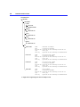
Appendix A The LAN Manager Root Directory . . . . . . . . . . . . . . . . . .
What the LAN Manager Root Directory Contains. . . . . . . . . . . . . . . . . .
Edits Made by Setup to System Files . . . . . . . . . . . . . . . . . . . . . . . . . . .
PROTOCOL.INI . . . . . . . . . . . . . . . . . . . . . . . . . . . . . . . . . . . . . . . . . . .
CONFIG.SYS . . . . . . . . . . . . . . . . . . . . . . . . . . . . . . . . . . . . . . . . . . . . .
AUTOEXEC.BAT . . . . . . . . . . . . . . . . . . . . . . . . . . . . . . . . . . . . . . . . .
STARTUP.CMD. . . . . . . . . . . . . . . . . . . . . . . . . . . . . . . . . . . . . . . . . . .
PRIVINIT.CMD . . . . . . . . . . . . . . . . . . . . . . . . . . . . . . . . . . . . . . . . . . .
LANMAN.DOS Enhanced Directory. . . . . . . . . . . . . . . . . . . . . . . . . . . . . .
The LANMAN.DOS\DRIVERS Directory. . . . . . . . . . . . . . . . . . . . . .
The LANMAN.DOS\LOGS Directory. . . . . . . . . . . . . . . . . . . . . . . . . .
The LANMAN.DOS\NETPROG Directory. . . . . . . . . . . . . . . . . . . . .
The LANMAN.DOS\SERVICES Directory . . . . . . . . . . . . . . . . . . . .
LANMAN.DOS Basic Directory. . . . . . . . . . . . . . . . . . . . . . . . . . . . . . . . . .
The LANMAN.DOS\BASIC Directory . . . . . . . . . . . . . . . . . . . . . . . . .
297
297
298
298
298
298
299
299
299
300
301
301
303
304
304
Contents
ix
LANMAN OS/2 Workstation Directory . . . . . . . . . . . . . . . . . . . . . . . . . . .
The LANMAN\DRIVERS Directory . . . . . . . . . . . . . . . . . . . . . . . . . . .
The LANMAN\LOGS Directory . . . . . . . . . . . . . . . . . . . . . . . . . . . . . . .
The LANMAN\NETLIB Directory . . . . . . . . . . . . . . . . . . . . . . . . . . . .
The LANMAN\NETPROG Directory . . . . . . . . . . . . . . . . . . . . . . . . . .
The LANMAN\SERVICES Directory. . . . . . . . . . . . . . . . . . . . . . . . . .
305
306
307
307
308
309
Appendix B The LANMAN.INI File . . . . . . . . . . . . . . . . . . . . . . . . . . . . . . . .
How to Override Values . . . . . . . . . . . . . . . . . . . . . . . . . . . . . . . . . . . . . . . . .
How to Change Values. . . . . . . . . . . . . . . . . . . . . . . . . . . . . . . . . . . . . . . . . . .
Adding Optional Entries. . . . . . . . . . . . . . . . . . . . . . . . . . . . . . . . . . . . . . . . . .
Why You Change Values. . . . . . . . . . . . . . . . . . . . . . . . . . . . . . . . . . . . . . . . .
The Last Line . . . . . . . . . . . . . . . . . . . . . . . . . . . . . . . . . . . . . . . . . . . . . . . . . . .
LANMAN.INI File Conventions . . . . . . . . . . . . . . . . . . . . . . . . . . . . . . . . . .
LANMAN.INI File Sections. . . . . . . . . . . . . . . . . . . . . . . . . . . . . . . . . . . . . .
The [networks] Section for MS-DOS . . . . . . . . . . . . . . . . . . . . . . . . . .
The [networks] Section for OS/2. . . . . . . . . . . . . . . . . . . . . . . . . . . . . . .
The [workstation] Section . . . . . . . . . . . . . . . . . . . . . . . . . . . . . . . . . . . . .
Default Entries . . . . . . . . . . . . . . . . . . . . . . . . . . . . . . . . . . . . . . . . . . . . .
Optional Entries. . . . . . . . . . . . . . . . . . . . . . . . . . . . . . . . . . . . . . . . . . . .
The [messenger] Section . . . . . . . . . . . . . . . . . . . . . . . . . . . . . . . . . . . . . .
The [netshell] Section . . . . . . . . . . . . . . . . . . . . . . . . . . . . . . . . . . . . . . . . .
The [loadopts] Section (MS-DOS Only) . . . . . . . . . . . . . . . . . . . . . . . .
The [services] Section . . . . . . . . . . . . . . . . . . . . . . . . . . . . . . . . . . . . . . . . .
Sample LANMAN.INI File . . . . . . . . . . . . . . . . . . . . . . . . . . . . . . . . . . . . . . .
LANMAN.INI File for LAN Manager Enhanced . . . . . . . . . . . . . . . .
LANMAN.INI File for LAN Manager Basic . . . . . . . . . . . . . . . . . . . .
Summary Tables . . . . . . . . . . . . . . . . . . . . . . . . . . . . . . . . . . . . . . . . . . . . . . . . .
The [networks] Section for MS-DOS . . . . . . . . . . . . . . . . . . . . . . . . . .
The [networks] Section for OS/2. . . . . . . . . . . . . . . . . . . . . . . . . . . . . . .
The [workstation] Section . . . . . . . . . . . . . . . . . . . . . . . . . . . . . . . . . . . . .
The [messenger] Section . . . . . . . . . . . . . . . . . . . . . . . . . . . . . . . . . . . . . .
The [netshell] Section . . . . . . . . . . . . . . . . . . . . . . . . . . . . . . . . . . . . . . . . .
The [loadopts] Section . . . . . . . . . . . . . . . . . . . . . . . . . . . . . . . . . . . . . . . .
The [services] Section . . . . . . . . . . . . . . . . . . . . . . . . . . . . . . . . . . . . . . . . .
311
312
312
312
313
313
313
314
315
315
317
317
318
330
331
332
332
333
333
334
336
336
336
336
338
338
338
338
x
Contents
Appendix C TCP/IP Protocol . . . . . . . . . . . . . . . . . . . . . . . . . . . . . . . . . . . . .
Before Installing TCP/IP . . . . . . . . . . . . . . . . . . . . . . . . . . . . . . . . . . . . . . . . .
Identifying Computers on the Network . . . . . . . . . . . . . . . . . . . . . . . . .
Matching LAN Manager Server Names to IP Addresses . . . . . . . . .
Advanced Concepts . . . . . . . . . . . . . . . . . . . . . . . . . . . . . . . . . . . . . . . . . . .
Tuning Microsoft TCP/IP . . . . . . . . . . . . . . . . . . . . . . . . . . . . . . . . . . . . . . . .
Adjusting Timing and Retry Parameters for Microsoft TCP/IP . . .
Microsoft TCP/IP and the Sockets Interface . . . . . . . . . . . . . . . . . . . .
The TCPUTILS.INI File . . . . . . . . . . . . . . . . . . . . . . . . . . . . . . . . . . . .
Loading Microsoft TCP/IP and Sockets. . . . . . . . . . . . . . . . . . . . . .
Running Microsoft TCP/IP Concurrently With Other Protocols . .
339
339
339
342
343
344
346
346
346
347
348
Appendix D Microsoft Data Link Control Protocol . . . . . . . . . . . . . . . . . .
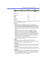
Installing the Microsoft DLC Protocol . . . . . . . . . . . . . . . . . . . . . . . . . . . .
PROTOCOL.INI Options . . . . . . . . . . . . . . . . . . . . . . . . . . . . . . . . . . . . .
Sample Configuration Files . . . . . . . . . . . . . . . . . . . . . . . . . . . . . . . . .
349
351
352
359
Appendix E Using the Network Application Starter . . . . . . . . . . . . . . . . .
The Appstart Command Line . . . . . . . . . . . . . . . . . . . . . . . . . . . . . . . . . . . . .
The APPSTART.INI File. . . . . . . . . . . . . . . . . . . . . . . . . . . . . . . . . . . . . . . . .
APPSTART.INI Example . . . . . . . . . . . . . . . . . . . . . . . . . . . . . . . . . . . . .
Administering Appstart. . . . . . . . . . . . . . . . . . . . . . . . . . . . . . . . . . . . . . . . . . .
Preparing to Use Appstart . . . . . . . . . . . . . . . . . . . . . . . . . . . . . . . . . . . . .
Managing a Central APPSTART.INI . . . . . . . . . . . . . . . . . . . . . . . . . . .
Managing User Workstations . . . . . . . . . . . . . . . . . . . . . . . . . . . . . . . . . .
361
363
364
367
367
367
368
368
Appendix F Excluding Memory From Windows . . . . . . . . . . . . . . . . . . .
Excluding a Segment of Memory . . . . . . . . . . . . . . . . . . . . . . . . . . . . . . . . .
Western Digital EtherCard Plus and EtherCard Plus/A. . . . . . . . . . .
IBM Token-Ring Network Adapter (1, 2, or A) . . . . . . . . . . . . . . . . .
3Com EtherLink II (3C503) and EtherLink 16 (3C507) Network
Adapters . . . . . . . . . . . . . . . . . . . . . . . . . . . . . . . . . . . . . . . . . . . . . . . . . . . . .
Other Types of Network Adapters . . . . . . . . . . . . . . . . . . . . . . . . . . . . .
369
370
371
371
. . . . . . . . . . . . . . . . . . . . . . . . . . . . . . . . . . . . . . . . . . . . . . . . . . . . . . . . . . . . . . . . . . . . . . . . . . .
375
. . . . . . . . . . . . . . . . . . . . . . . . . . . . . . . . . . . . . . . . . . . . . . . . . . . . . . . . . . . . . . . . . . . . . . . . . . . . .
389
Glossary
Index .
373
373
1
Before You Begin
The Installation Guide for Clients is written for administrators of
Microsoft® Windows NT™ networks that will include LAN Manager
workstations. It covers the installation of MS-DOS® Basic and Enhanced
workstations, including Enhanced workstations running the
Microsoft Windows™ operating system. It also covers the installation of
OS/2® workstations.
This manual helps you plan the installation of your LAN Manager
workstations, and shows you how to install and configure the software.
It also provides reference information for the device drivers used with
LAN Manager workstations.
Note This installation package is for new installations only. It cannot be
used to upgrade from existing LAN Manager workstation software. If
you already have a version of LAN Manager running on the workstation,
you can use it to connect to a Windows NT network, but you will not
have the refinements included in this version of LAN Manager. If you
want to install this version, follow the directions in your LAN Manager
documentation to remove it. Then, install the workstation software
according to the directions in this manual.
This manual assumes that you understand the Microsoft Windows NT
operating system, MS-DOS and OS/2. If you are not familiar with these
operating systems, see your Windows NT, MS-DOS and OS/2 manuals.
2
Installation Guide for Clients
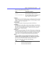
How to Use This Manual
Turn to the part of this manual that contains the information you need:
Part 1, “Overview, Preparation, and Planning”
This part describes the preparations you must make to install and
configure LAN Manager on MS-DOS and OS/2 computers.
Part 2, “Installing LAN Manager Workstation Software ”
This part tells you how to install LAN Manager workstation software
on MS-DOS and OS/2 computers.
Part 3, “Managing Your LAN Manager Configuration”
This part tells you how to change network adapter driver, protocol,
workstation, server, and service parameters; how to install and
manage connectivity products; and how to detach, attach, and remove
LAN Manager workstation software.
Part 4, “Network Device Drivers”
This part provides information about installing and using network
device drivers (the software that enables LAN Manager to work with
network adapters) on OS/2 and MS-DOS computers. It also explains
how to change the options that control the network device drivers.
Appendixes
The appendixes contain information on the LAN Manager root
directory, LANMAN.INI file, TCP/IP protocol, Microsoft Data Link
Control (DLC) protocol, Using the Network Application Starter, and
excluding memory from Microsoft Windows.
Before You Begin
3
Documentation Conventions
This manual uses several type styles and special characters:
Convention
Use
bold
Represents commands, command options, and file entries. Type
bold words exactly as they appear (for example, net use).
Introduces new terms and represents variables. For example,
the variable computername indicates that you type the name
of a workstation or a server.
Represents examples, screen displays, and error messages.
Represents filenames and paths. You can, however, type
entries in uppercase or lowercase letters, or a combination of
the two.
Represents key names (for example, CTRL, ENTER, and F2).
italic
monospace
ALL
CAPITALS
SMALL
CAPITALS
KEY+KEY
{braces}
[brackets]
| (vertical bar)
... (ellipsis)
Û
Indicates that you press two keys at the same time. You must
hold down the first key while you press the second. For
example, Press CTRL+Z means to hold down CTRL while you
press Z.
Encloses required items in syntax statements. For example,
{yes | no} indicates that you must specify yes or no when
using the command. Type only the information within the
braces, not the braces themselves.
Encloses optional items in syntax statements. For example,
[password] indicates that you can choose to type a password
with the command. Type only the information within the
brackets, not the brackets themselves.
Stands for “or” and separates items within braces or brackets.
For example, {/hold | /release | /delete} indicates that you
must type /hold or /release or /delete.
Indicates that you can repeat the previous item(s) in syntax
statements. For example, /route:devicename[,...] indicates that
you can specify more than one device, putting commas
between the devicenames.
Indicates a procedure.
4
Installation Guide for Clients
Finding Further Information
This manual is written for network administrators. In addition to
reading this manual, be sure to read the README.TXT or
README.DOC files included with LAN Manager. These files are
located in the LAN Manager root directory. These online files contain
additional important information about LAN Manager, and they include
information that was not available when the manuals were printed.
This manual set includes the following:
User’s Guide for MS-DOS Clients
Provides information about using LAN Manager with MS-DOS
workstations. It includes information about both LAN Manager Basic
and LAN Manager Enhanced, using Novell® NetWare® Connectivity
at a workstation, and accessing the network from a remote
workstation.
User’s Guide for OS/2 Clients
Provides information about using LAN Manager with OS/2
workstations.
User’s Guide for Microsoft Windows Clients
Provides instructions on how to log on and off, send and receive
messages, and browse, connect to, and disconnect from network
resources, all through Windows icons.
NetWare Connectivity Guide
Provides information about installing and administering NetWare®
Connectivity, which allows MS-DOS workstations to access Novell
NetWare servers as well as Windows NT computers and
LAN Manager servers.
P A R T
1
Overview, Preparation, and
Planning
Chapters
1 Introduction ......................................................................................7
2 Planning for Installation and Configuration......................................13
7
C H A P T E R
1
Introduction
The LAN Manager Setup program is used to install and configure
LAN Manager on OS/2 and MS-DOS computers.
• When you install LAN Manager, the Setup program leads you, step-
by-step, through installation using a series of dialog boxes. Your
responses to the dialog box questions determine the type of
workstation and the exact LAN Manager configuration that will be
installed.
• To review or change the configuration of an existing LAN Manager
workstation, you use the LAN Manager Setup screen. The Setup
screen provides menus and commands that you use to change driver,
protocol, workstation, and service settings; to install and manage
connectivity products; and to detach, attach, and remove
LAN Manager software.
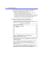
Using the Setup Program’s Interface
The LAN Manager Setup program is easy to use. First, however, you
must know some simple techniques for moving around in dialog boxes
or in the Setup screen using a mouse and/or the keyboard.
Scrolling
When more text is available than can fit at one time within a dialog box
or a list box, a scroll bar (a vertical bar with an arrow at each end)
appears at the right of the box. You can move through the available
information by clicking the scroll bar with a mouse or by pressing the
PAGE DOWN and PAGE UP keys.
8
Installation Guide for Clients
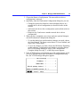
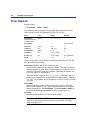
Using the Keyboard
Use the following keys in both the Setup program dialog boxes and in
the Setup screen:
Key
Function
ALT
Selects the menu bar in the Setup screen. Then press TAB,
SHIFT+TAB, LEFT ARROW, or RIGHT ARROW to move to the
menu you want.
Denoted by an underlined or highlighted letter in a menu,
command, or command button.
Pressing ALT and the Access key chooses that menu or
command button.
When a menu’s commands are displayed, ALT is not required.
Pressing the access letter alone chooses the command.
Moves the selection left, right, up, or down within the menu
bar, a menu, a text box, a list box, or a range of choices.
Positions the cursor at the end of a selected text field.
Invokes the selected command or command button.
Cancels the current dialog box or menu and returns to the
previous dialog box or to the Setup screen. In a dialog box,
ESC is equivalent to choosing the Cancel button.
Accesses online help from within a dialog box. Pressing F1 is
equivalent to choosing the Help button.
Selects the menu bar in the Setup screen. Then press TAB,
SHIFT+TAB, LEFT ARROW, or RIGHT ARROW to move to the
menu you want.
Moves the cursor to the beginning of a selected text field.
Scrolls down one page within a dialog box or a list box. PAGE
DOWN works only when a scroll bar appears at the right of the
box.
Scrolls up one page within a dialog box or list box. PAGE UP
works only when a scroll bar appears at the right of the box.
Selects or clears (turns on or off) a selected check box.
Moves to the next menu or to the next field in a dialog box.
Moves to the previous menu or to the previous field in a
dialog box.
Access
ARROW
END
ENTER
ESC
F1
F10
HOME
PAGE DOWN
PAGE UP
SPACEBAR
TAB
SHIFT+TAB
Chapter 1 Introduction
9
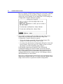
Online Help
The LAN Manager Setup program offers you two types of online help:
help for dialog boxes and menu-based help.
• Help for dialog boxes is available from most of the LAN Manager
Setup dialog boxes that appear when you install or configure
LAN Manager software. When you choose a dialog box’s Help
button or press the F1 key, a help dialog box appears, providing
information specific to that LAN Manager Setup dialog box.
• Menu-based help is available from the Help menu when you use the
Setup screen (when you are reviewing or configuring an existing
installation). Some Help menu commands take you directly to a help
dialog box. Other Help menu commands take you first to a list box of
help topics; after you select a help topic, the commands take you to
the help dialog box for the selected help topic.
Help dialog boxes work exactly like other LAN Manager Setup dialog
boxes. When more text is available than can fit at one time within the
help dialog box, you can scroll through the text by clicking the scroll
bar or by pressing the
PAGE DOWN and PAGE UP keys.
10
Installation Guide for Clients
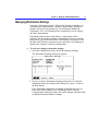
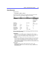
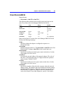
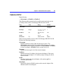
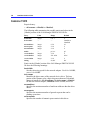
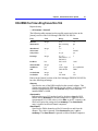
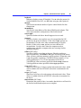
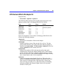
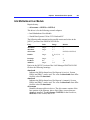
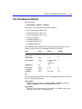
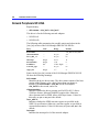
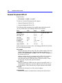
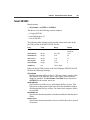
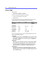
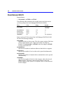
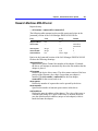
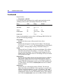
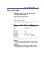
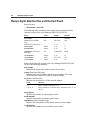
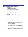
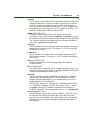
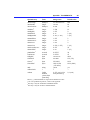
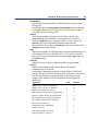
System Requirements
Before installing LAN Manager, check that your system meets the
following requirements. The following tables list the processor type,
memory, and operating system needss for LAN Manager workstations.
The following table shows the processors required for different
LAN Manager configurations.
Processor Requirements
LAN Manager configuration
8086/88
286
386
486
MS OS/2 1.x workstation
IBM OS/2 2.0 workstation
MS-DOS Enhanced workstation
MS-DOS Basic workstation
No
No
Yes
Yes
Yes
No
Yes
Yes
Yes
Yes
Yes
Yes
Yes
Yes
Yes
Yes
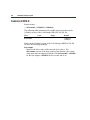
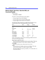
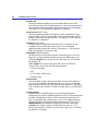
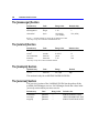
The following table shows the recommended system memory and disk
storage space for different LAN Manager configurations.
System Memory and Disk Storage Requirements
LAN Manager
configuration
MS-DOS Enhanced
workstation
MS-DOS Basic
workstation
MS OS/2 1.x workstation
IBM OS/2 2.0 workstation
Recommended
memory
Minimum free
disk space
640K plus extended or
expanded memory
640K
4 MB
4.5 MB
5.5 MB
5 MB
5 MB
1 MB
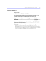
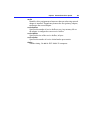
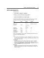
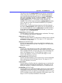
The following table shows operating system requirements for different
LAN Manager configurations.
Operating System Requirements
LAN Manager
configuration
MS-DOS Enhanced
workstation
MS-DOS Basic
workstation
MS OS/2 workstation
MS-DOS
3.3 or
later*
Microsoft
Windows
3.0 or
later
MS OS/2
1.21 or
1.3**
IBM OS/2
2.0
Yes
Yes
No
No
Yes
Yes
No
No
No
No
Yes
Yes
* PC-DOS version 3.3 or later is also compatible
**IBM OS/2 Standard Edition version 1.2 corrective service diskette (CSD) XR04053 is
compatible.
Chapter 1 Introduction
11
Before Installing
Before you can install LAN Manager, the computer’s operating system
must be installed. Before you begin to install LAN Manager, have these
items at hand:
• Manuals for the computer.
• Manuals for the operating system.
• If needed, a supplemental drivers disk that contains a network adapter
driver or a protocol.
Also, before you begin to install LAN Manager, determine the
following:
• The amount of random access memory (RAM) installed in the
•
•
•
•
computer.
The manufacturer’s name and the model of each network adapter
installed in the computer, and the settings used for each adapter.
The names of all protocols that you will be using.
The name of the domain or workgroup (a number of computers
grouped for administrative and security purposes) in which the
computer will be a member.
If you are installing TCP/IP, the addresses and subnet masks.
Chapter 2 contains forms to collect the information you need to install
LAN Manager.
12
Installation Guide for Clients
13
C H A P T E R
2
Planning for Installation and
Configuration
This chapter helps you make the decisions necessary to install and
configure LAN Manager workstations. (Workstations are also referred
to as clients.) This chapter provides the following:
• Forms for planning and recording the LAN Manager workstation
configurations
• Detailed information for planning LAN Manager installations and
configurations on MS-DOS and OS/2 computers
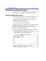
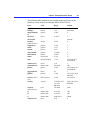
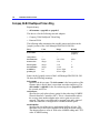
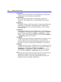
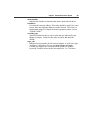
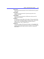
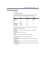
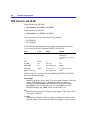
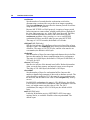
Configuration Planning Forms
Configuration planning forms are provided here to help you prepare to
install LAN Manager workstation software. The forms list the
information you will need to provide when installing or configuring
LAN Manager workstations. Where appropriate, the forms list the
possible range of values that can be used for a given parameter, and
they show the LAN Manager default setting (if one exists) for that
parameter.
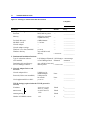
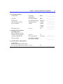
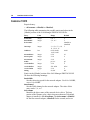
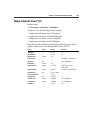
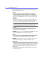
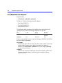
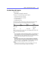
There are three planning forms:
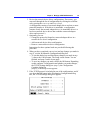
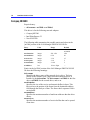
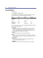
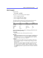
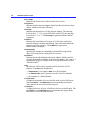
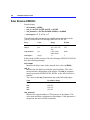
• Figure 2.1, Planning for MS-DOS Enhanced Workstations
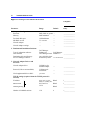
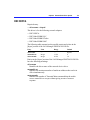
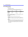
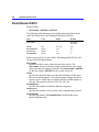
• Figure 2.2, Planning for MS-DOS Basic Workstations
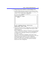
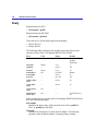
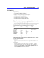
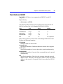
• Figure 2.3, Planning for OS/2 Workstations
Two sections follow the forms to explain and interpret the information
in the forms: “Planning for LAN Manager Installations on MS-DOS
Computers,” and “Planning for LAN Manager Installations on OS/2
Computers.” It is recommended that you photocopy the configuration
planning forms and fill them in while reading those sections.
You can then use the completed forms as a ready reference during
installation or configuration of individual workstations. You can also
save and file the forms as a written record of the workstation
configurations on your network.
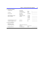
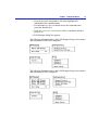
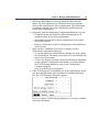
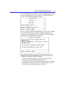
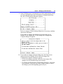
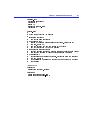
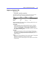
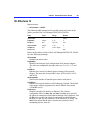
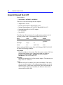
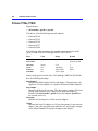
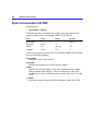
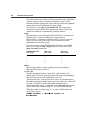
14
Installation Guide for Clients
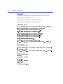
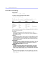
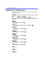
Figure 2.1 Planning for Enhanced MS-DOS Workstations
Computer:
Parameter
1. Computer Configuration
Processor
Memory
Free hard disk space
MS-DOS version
Network adapter
Network adapter settings
Windows 3.0 (or later) installed?
Windows directory
Range
Default
Entry
8088, 8086 or greater
640K plus extended or
expanded memory
4 MB minimum
3.3 or later
—
—
yes or no
Any valid drive and
directory
—
______________
—
—
—
—
—
—
______________
______________
______________
______________
______________
______________
C:\WINDOWS
______________
2. Fundamental Installation Decisions
Type of workstation software
LAN Manager Enhanced LAN Manager LAN Manager
to be installed
or LAN Manager Basic Enhanced
Enhanced
______________
Destination drive and directory
Any valid drive letter and
for LAN Manager software
directory name
C:\LANMAN.DOS ______________
3. Network Adapter Drivers and
Protocols
Network adapter driver
Protocols (if driver not monolithic)
Need supplemental drivers disk?
Valid driver for
installed adapter
Valid protocols
for network
yes or no
TCP/IP Settings (required when the TCP/IP protocol is
selected)
IP address
www.xxx.yyy.zzz
where w, x, and y
are 0-255 and z is
Subnet mask
1-254
Default gateway
Number of NetBIOS sessions
1-22
None
______________
None
—
______________
______________
Blank
*______________
Blank
*______________
Blank
6
______________
*______________
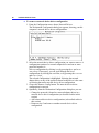
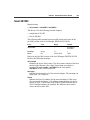
Chapter 2 Planning for Installation and Configuration
4. Workstation Settings
Computername
Username
Domain name
Other domains to monitor
(up to 4 domains)
Any unique
computername
Any valid username
Any valid domain name
Valid domain name
or blank
Messaging service?
yes or no
5. Running with the Windows
Operating System
Run LAN Manager with the
Windows Operating System?
Location of WIN.INI file
Display messages
* Entry required
Blank
*______________
Blank
DOMAIN
1. Blank
2. Blank
3. Blank
4. Blank
yes
*______________
*______________
______________
______________
______________
______________
______________
yes or no
yes
C:\WINDOWS
Drive and Directory
Only while the Windows
environment is running —
6. MS-DOS Memory Management
(If applicable)
Should LAN Manager modify system
files to maximize application memory? yes or no
15
yes
______________
______________
______________
______________
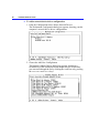
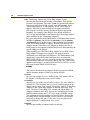
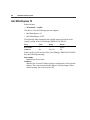
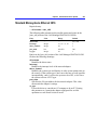
16
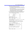
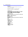
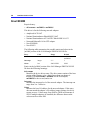
Installation Guide for Clients
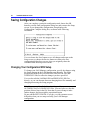
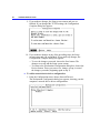
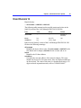
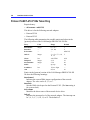
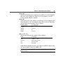
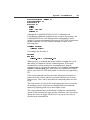
Figure 2.2 Planning for Basic MS-DOS Workstations
Computer:
Parameter
Range
Default
1. Computer Configuration
Processor
Memory
Free hard disk space
MS-DOS version
Network adapter
Network adapter settings
8088, 8086, or greater —
640K minimum
—
1 MB minimum
—
3.3 or newer
—
—
—
—
—
Entry
______________
______________
______________
______________
______________
______________
2. Fundamental Installation Decisions
Type of workstation software
to be installed
Destination drive and directory
for LAN Manager software
3. Network Adapter Drivers and
Protocols
Network adapter driver
Protocol (if driver not monolithic)
Need supplemental drivers disk?
LAN Manager
Enhanced or
LAN Manager
LAN Manager Basic Enhanced
______________
Any valid drive letter
and directory name C:\LANMAN.DOS ______________
Valid driver for
installed adapter
Valid protocol
for network
yes or no
—
______________
—
—
______________
______________
TCP/IP settings (required when the TCP/IP protocol is
selected)
Blank
IP address
www.xxx.yyy.zzz
where w,x, and y are
0-255 and z is
Blank
Subnet mask
1-254
Blank
Default gateway
Number of NetBIOS sessions
1-22
6
*______________
*______________
______________
*______________
Chapter 2 Planning for Installation and Configuration
4. Workstation Settings
Computername
5. MS-DOS Memory Management
(If applicable)
Should LAN Manager modify system
files to maximize application memory?
* Entry required
17
Any unique
computername
Blank
*______________
yes or no
yes
______________
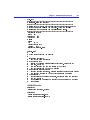
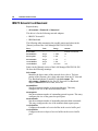
18
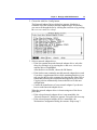
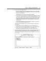
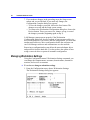
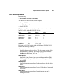
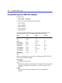
Installation Guide for Clients
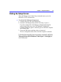
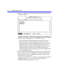
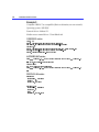
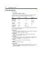
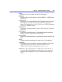
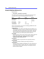
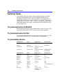
Figure 2.3 Planning for OS/2 Workstations
Parameter
Range
Default
Entry
1. Computer Configuration
Processor
Memory
Free hard disk space
Network adapter
Network adapter settings
OS/2 version
286 or greater
4.5 MB recommended
5 MB minimum
—
—
1.21, 1.3, or 2.0
—
—
—
—
—
—
______________
______________
______________
______________
______________
______________
C:\LANMAN
______________
None
______________
None
—
______________
______________
Blank
*______________
Blank
*______________
Blank
40
______________
*______________
2. Fundamental Installation Decisions
Destination drive and directory
Any valid drive letter
for LAN Manager software
and directory name
3. Network Adapter Drivers and
Protocols
Network adapter driver
Protocols
(if driver not monolithic)
Need supplemental drivers disk?
Valid driver for
installed adapter
Valid protocols
for network
yes or no
TCP/IP Settings (required when the TCP/IP protocol is
selected)
IP address
www.xxx.yyy.zzz
where w, x, and y
are 0-255 and z is
Subnet mask
1-254
Default gateway
Number of NetBIOS sessions
1-254
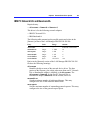
Chapter 2 Planning for Installation and Configuration
4. Workstation Settings
Computername
Other domains to monitor
(up to 4 domains)
Any unique
computername
Any valid username
Any valid
domain name
Valid domain name
or blank
Autostart Messenger service?
Autostart Netpopup service?
yes or no
yes or no
Username
Domain name
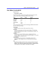
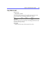
5. Service Parameters
Messenger service:
Message log filename
Message buffer size
* Entry required
19
Blank
Blank
DOMAIN
*______________
*______________
*______________
1. Blank
2. Blank
3. Blank
4. Blank
yes
yes
______________
______________
______________
______________
______________
______________
Valid filename with .LOG
MESSAGES.LOG ______________
extension
512-62000 bytes
4096
______________
20
Installation Guide for Clients
Planning for LAN Manager Installations on MS-DOS
Computers
This section explains the information that was introduced earlier in this
chapter, in “Configuration Planning Forms.” It provides information
and concepts you should understand before you begin to install or
configure LAN Manager workstation software on MS-DOS computers.
It is a good idea to photocopy the configuration planning forms and fill
them in while reading this section. You can then use the completed
planning forms as you perform the installation tasks described in Part 2,
“Installing LAN Manager Workstation Software,” and the configuration
tasks described in Part 3, “Managing Your LAN Manager Software
Configuration.”
Computer Configuration
Before you install LAN Manager on an MS-DOS computer, determine
its configuration.
Processor
The computer’s processor must be 8088 or greater. The following
processors are supported for both LAN Manager Basic and Enhanced
workstations: 8088, 8086, 286, 386, and 486.
Memory
The recommended random access memory (RAM) is 640K plus
extended or expanded memory for a LAN Manager Enhanced
workstation; the minimum recommended RAM is 640K for a
LAN Manager Basic workstation.
Free hard disk space
An Enhanced workstation must have at least 4 MB of free hard disk
space. A Basic workstation must have at least 1 MB free.
MS-DOS version
Both Basic and Enhanced workstations must have MS-DOS version
3.3 or later installed.
Chapter 2 Planning for Installation and Configuration
21
Network adapter
To communicate over the network, a computer must have at least one
network adapter installed. You must know the type of each adapter
installed so that you can determine the appropriate network adapter
driver and protocol, and you must know the settings used for each
network adapter. (For more information about network adapters,
settings, and network adapter drivers, see Part 4, “Network Device
Drivers.”)
Windows
Determine whether Microsoft Windows version 3.0 or later is
installed. If so, determine the directory in which it is located.
Fundamental Installation Decisions
When installing, you will be asked which type of LAN Manager
workstation software to install on MS-DOS computers: LAN Manager
Enhanced or LAN Manager Basic.
Enhanced workstations
Can connect to network directories and printers, send and receive
network messages, and use other network resources and services
(such as IPC network named pipes). Named pipes are an interprocess
communication (IPC) method for remote program execution and
other distributed applications. At a LAN Manager Enhanced
workstation, you can issue network commands from the command
line or from the LAN Manager screen. This is the default selection for
MS-DOS computers.
Basic workstations
Can use network resources and services, and connect to network
directories and printers. At a LAN Manager Basic workstation, you
can issue network commands only from the command line. Basic
workstations use less memory than Enhanced workstations.
During installation, you will also be asked where on the computer the
LAN Manager software should be installed. If it does not already exist,
the software creates the directory you specify. Any valid drive and
directory name is acceptable. The default is C:\LANMAN.DOS.
22
Installation Guide for Clients
Network Adapter Drivers and Protocols
When installing, you’ll need to provide information about the
computer’s network adapter and network adapter drivers.
LAN Manager uses network device drivers (software that coordinates
between the computer’s software and hardware) to operate the network
adapter(s) in the computer. Network adapter drivers control the physical
function of the network adapters, and protocol drivers bind to the
network adapter driver.
During installation or configuration, you will be shown lists of the
available network adapter drivers and the available protocols, and you
must choose one or more of each for installation on the workstation.
The network adapter driver you select must support the network adapter
installed in the computer. You must also select one or more protocols to
associate with the selected network adapter driver. The protocol you
select must be supported by your network.
LAN Manager includes many device drivers that work with many types
of network adapters. Or you can also install network device drivers
from a supplemental drivers disk prepared for LAN Manager
installation. (Usually, the manufacturer of the network adapter supplies
this disk, or you can create a supplemental drivers disk. For more
information, see Chapter 10, “Creating Supplemental Drivers Disks.”)
Network adapter driver
You must choose one or more network adapter drivers. The driver(s)
must support the network adapter installed in the computer, and the
settings used for that adapter.
During installation, you can select No Driver as the network adapter
driver. This allows you to complete an installation without specifying
a network adapter driver or a protocol. However, the computer
cannot communicate on the network until you select a valid network
adapter driver and a protocol from the Setup screen of the installed
workstation. The No Driver option is typically used when setting up a
workstation to use the Remote Access Service to access the network
from a remote site via a modem. When the Remote Access Service is
used, no network adapter card or network device driver is required.
For more information about installing and using the Remote Access
Service, see the User’s Guide for MS-DOS Clients.
Chapter 2 Planning for Installation and Configuration
23
Some network adapter drivers are monolithic. A monolithic driver
acts as both a network adapter driver and a protocol, and it does not
require that another protocol be selected and bound to it. Only one
monolithic driver, the loopback driver, is provided with
LAN Manager. This driver lets a computer with no network adapter
run LAN Manager for testing purposes. (For more information about
the loopback driver, see Part 4, “Network Device Drivers.”)
Protocols
You must also choose one or more protocols to bind to each selected
network adapter driver. If the network adapter driver is monolithic,
however, you cannot choose a protocol to be bound to it.
A Basic workstation can have one network adapter with one protocol.
For more information about network adapter drivers and protocols, see
Part 4, “Network Device Drivers.” For information about network
adapter settings, see Part 4 and your network adapter manual(s).
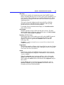
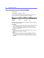
TCP/IP Settings
When you select the TCP/IP protocol, you can specify four parameters.
IP address
The internet protocol address, a unique number that identifies the
computer to other computers on the network. The IP address has four
fields separated by periods, in the form:
w.x.y.z
The range for the first three fields (w, x, and y) is 0 through 255. The
range for the last field is 1 through 254. The IP address setting
requires an entry.
Subnet mask
A series of bits used to identify the subnet number portion of an IP
address. The Subnet mask has four fields separated by periods, in the
form:
w.x.y.z
The range for the first three fields (w, x, and y) is 0 through 255. The
range for the last field (z) is 1 through 254. The Subnet mask setting
is required.
Default gateway (router)
The IP address of the default router used. A router is a hardware
device that connects networks together to create an internetwork.
The Default gateway (router) has four fields separated by periods, in
the form:
w.x.y.z
The range for each of the four fields is 0 through 255. The Default
gateway (router) setting is optional.
24
Installation Guide for Clients
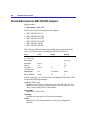
Number of NetBIOS sessions
The number of NetBIOS sessions. For MS-DOS workstations, the
range is 1 through 22; the default is 6. An entry is required.
The TCP/IP protocol can be bound to only one network adapter driver
for each workstation. If the TCP/IP protocol is bound to more than one
network adapter driver on a workstation, only the first binding is
effective; all subsequent bindings of TCP/IP to network adapter drivers
are ignored.
If you load three or more protocols, make sure that TCP/IP is not the
last protocol loaded.
For more information about TCP/IP, see Appendix C, “TCP/IP
Protocol.”
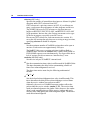
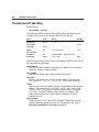
Workstation Settings
During installation and configuration, you must specify various
workstation settings in the “Workstation Settings” dialog box.
A Basic workstation has only one workstation setting, the
computername.
Computername
The name by which the network identifies a computer. The
computername can have as many as 15 characters, and it can contain
letters, numerals, and these characters:
!#$%&()^_' {}~
The computername cannot be the same as a domain name. It must be
unique on the local area network or any other network to which this
computer is connected, although it can be the same as the username.
The default is blank (no entry). A computername is required for both
Enhanced and Basic workstations.
For a Basic workstation only, the computername also serves as the
username.
Username
The name by which the network identifies the user and the name to
which you assign permissions to use resources. The username can
have as many as
20 characters, and it can contain letters, numerals, and these
characters:
!#$%&()^_' {}~
The username can be identical to the computername. The default is
blank (no entry). A username is required only for Enhanced
workstations. (For Basic workstations only, the computername serves
as the username.)
Chapter 2 Planning for Installation and Configuration
25
Domain name
The name of the domain or workgroup to which a workstation
belongs. It can have as many as 15 characters, and it can contain
letters, numerals, and these characters:
!#$%&()^_' {}~
An entry is required. The default is DOMAIN. An entry is required.
Other domains to monitor
Other Windows NT Advanced Server or LAN Manager domains in
which a workstation can participate, which means the net view
command will display servers from monitored domains, and this
workstation will receive domain-wide broadcasts sent to those
domains.
This workstation can monitor as many as four other domains. An
entry can be any valid domain name. The default is no entry (blank).
This entry is optional.
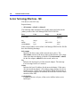
Messaging services
Allows the workstation to send and receive messages over the
network. This can be set to yes or no, and is a valid selection only for
Enhanced workstations. The default is yes.
Running LAN Manager with the Windows Operating System
The following parameters apply only to Enhanced workstations running
MS-DOS.
During installation, after you specify workstation settings, Setup checks
to see whether the Microsoft Windows operating system is installed on
the computer. If the WIN.INI file is not found, you are prompted to
provide the drive letter and path (for example, C:\WINDOWS).
If Setup finds that Microsoft Windows is installed, you must choose
whether or not to run LAN Manager with Windows. Choose yes or no;
the default is yes.
If you’ve chosen to run the Messenger service on the computer, Setup
prompts you to choose how LAN Manager will display messages on
this computer. The settings are Only while the Windows environment is
running or While the Windows environment or MS-DOS is running; the
default is Only while the Windows environment is running. The Only
while the Windows environment is running setting will also display
messages in the Windows operating system’s MS-DOS window.
Note When you select While the Windows environment or MS-DOS is
running, about 20K of this computer’s memory will be used for the
message display service. If you choose Only while the Windows
environment is running, about 4K of this computer’s memory will be
used for the message display service.
26
Installation Guide for Clients
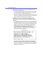
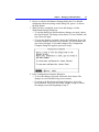
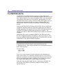
Using Stacker with LAN Manager
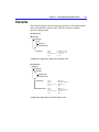
If you are using Stacker®with LAN Manager, the lines in CONFIG.SYS
that specify Stacker should come before the line that begins device=
and contains \protman.dos. This allows for the possibility that the
network drivers may be on either the stacked or unstacked portion of
the hard drive. Drivers that are loaded before Stacker must exist on the
unstacked portion of the hard drive. The Stacker lines will look
something like this:
devicehigh=c:\stacker\stacker.com d:\stacvol.dsk c:\stacvol.dsk
device=c:\stacker\sswap.com c:\stacvol.dsk /sync
device=c:\stacker\sswap.com d:\stacvol.dsk
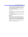
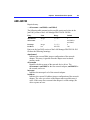
MS-DOS Memory Management
You must specify the following information for both Basic and
Enhanced workstations.
Optimize Memory
If a computer has more than 640K of memory or is running MS-DOS
5.0 or later, during installation the Setup program prompts you to
choose whether or not memory usage should be optimized on this
computer. Memory optimization involves the installation or updating of
expanded or extended memory managers on the computer. You can
choose yes or no; the default is yes.
Using a memory manager with LAN Manager makes additional space
available in MS-DOS conventional memory (the first 640K of memory
in the computer). If you don’t use a memory manager, LAN Manager
must load all of its software into conventional memory, using about
50K for LAN Manager Basic or about 120K for LAN Manager
Enhanced.
LAN Manager 2.2 includes two memory managers for MS-DOS:
HIMEM.SYS and EMM386.EXE.
HIMEM.SYS
For extended memory, the memory from 1 MB (1024K) to 16 MB
(16384K) on 286 and higher computers. The high-memory area
(HMA) is the first 64K of extended memory; only one application at a
time can use it. HIMEM.SYS coordinates access to the HMA.
Extended memory is also known as extended memory specification
(XMS) memory.
Chapter 2 Planning for Installation and Configuration
27
Using LAN Manager with HIMEM.SYS requires:
• MS-DOS version 3.3 or later
• LAN Manager Enhanced or Basic workstation software
• 64K or more of extended memory
If this computer is currently running HIMEM.SYS, LAN Manager
does not replace the existing HIMEM.SYS file.
EMM386.EXE
For emulating expanded memory, a section of extended memory
configured for the Lotus/Intel/Microsoft (LIM) 4.0 expanded memory
specification (EMS) on 386 and higher computers. EMM386.EXE
may be named EMM386.SYS in other applications.
When used with MS-DOS 5.0 or higher, EMM386.EXE also
provides access to upper memory blocks (UMBs) between 640K and
1 MB.
Using LAN Manager with EMM386.EXE requires:
• MS-DOS version 3.3 or later
• 64K or more of extended memory
• No physical expanded memory installed in the computer
• HIMEM.SYS installed
When installing LAN Manager from disk, Setup checks whether the
workstation is already using an extended or an expanded memory
manager, and whether that memory manager is a version supported by
LAN Manager. If not, Setup notifies you that updated memory
managers are now available on the workstation’s hard disk.
See the manual(s) for the existing memory manager, and then decide if
you want to install the LAN Manager versions. After you finish
configuring this workstation, you can replace the old memory manager
with the new one by copying the new file over the old file.
If you already use a Microsoft Windows memory manager, you do not
need to replace it with the LAN Manager memory manager, because
they are the same file.
28
Installation Guide for Clients
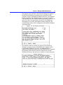
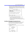
Using Third Party Memory Managers for Workstations
Before running the optimization or configuration program of a third
party memory manager, edit AUTOEXEC.BAT to comment out (add a
REM statement at the beginning of) the net start workstation line and
any lines loading protocols. Then edit CONFIG.SYS to comment out
the line that specifies the path to PROTMAN.DOS. It will look
something like this:
device = c:\lanman.dos\drivers\protman\protman.dos
After the program is finished configuring the system, remove the REM
statements from these lines in both files.
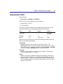
Avoiding R:BASE/LAN Manager Conflicts
On MS-DOS Enhanced workstations that are using Expanded Memory
Services (EMS) and R:BASE, be sure to set lim=no in the
[workstation] section of your LANMAN.INI file (or use the /lim:no
switch with the net start workstation command). This avoids conflicts
between R:BASE and LAN Manager for expanded memory.
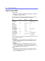
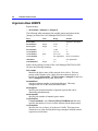
Encryption
Encryption converts usernames and passwords into a coded form for
extra security before transmitting them over the network. When
LAN Manager is installed on MS-DOS workstations, encryption is
always set to on. Encryption uses about 3K of the computer’s memory.
You can eliminate that memory use by editing the LANMAN.INI file
and removing the encrypt entry from the wrkservices line in the
[services] section. However, you should usually leave encryption turned
on, especially when you want to encrypt the usernames and passwords
that are transmitted over your network.
Chapter 2 Planning for Installation and Configuration
29
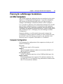
Planning for LAN Manager Installations
on OS/2 Computers
This section explains the information that was introduced earlier in this
chapter, in “Configuration Planning Forms.” It provides information
and concepts you should understand before you begin to install or
configure LAN Manager workstation software on OS/2 computers.
It is a good idea to photocopy the configuration planning forms and fill
them in while reading this section. You can then use the completed
planning forms as you perform the installation tasks described in Part 2,
“Installing LAN Manager Workstation Software,” and the configuration
tasks described in Part 3, “Managing Your LAN Manager Software
Configuration.”
During installation, you will be asked where on the computer the
LAN Manager software should be installed. If it does not already exist,
the software creates the directory you specify. Any valid drive and
dirrectory name is acceptable. The default is C:\LANMAN.
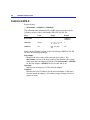
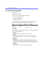
Computer Configuration
First, determine the configuration of the computer on which you will
install LAN Manager.
Processor
The processor must be 286 or greater.
Memory
The recommended minimum random access memory (RAM) is 4.5
MB for an OS/2 workstation.
Free hard disk space
An OS/2 workstation must have at least 5 MB hard disk space free.
Display monitor
Presentation Manager only supports CGA and better monitors. Do
not install OS/2 1.3 on computers using monochrome monitors other
than VGA monochrome monitors.
30
Installation Guide for Clients
Network adapter
To communicate over the network, a computer must have at least one
network adapter installed. You must know each adapter that is
installed so that you can determine the appropriate network adapter
driver and protocol, and you must know the settings that have been
used for each network adapter. (For more information about network
adapters, settings, and network adapter drivers, see Part 4, “Network
Device Drivers.”)
OS/2 version
Determine which version of OS/2 you are using. For information
about which versions of OS/2 work with LAN Manager, see
Chapter 1, “Introduction.”
Network Adapter Drivers and Protocols
When installing, you’ll need to provide information about the
computer’s network adapters and network adapter drivers.
A device driver is software that coordinates between the computer’s
software and hardware. LAN Manager uses a kind of device driver
called network adapter drivers to operate the network adapter(s) in the
computer. Network adapter drivers control the physical function of the
network adapters, and protocol drivers bind to the network adapter
drivers.
During installation or configuration, you will be shown lists of the
available network adapter drivers and the available protocols, and you
must choose one or more of each for installation on the workstation.
The network adapter driver you select must support the network adapter
installed in the computer. You must also select one or more protocols to
associate with the selected network adapter driver. The protocol(s) you
select must be supported by your network.
LAN Manager includes many device drivers that work with many types
of network adapters. Or you can also install network device drivers
from a supplemental drivers disk prepared for LAN Manager
installation. (Usually, the manufacturer of the network adapter supplies
this disk, or you can create a supplemental drivers disk. For more
information, see Chapter 10, “Creating Supplemental Drivers Disks.”)
Chapter 2 Planning for Installation and Configuration
31
Network adapter driver
You must choose one or more network adapter drivers. The driver(s)
must support the network adapter installed in the computer, and the
settings used for that adapter.
During installation, you can select No Driver as the network adapter
driver. This allows you to complete an installation without specifying
a network adapter driver or a protocol. However, the computer
cannot communicate over the network until you select a valid
network adapter driver and a protocol from the Setup screen of the
installed workstation.
Some network adapter drivers are monolithic. A monolithic driver
acts as both a network adapter driver and a protocol, and it does not
require that another protocol be selected and bound to it. Only one
monolithic driver, the loopback driver, is provided with
LAN Manager. This driver lets a computer with no network adapter
run LAN Manager for testing purposes. (For more information about
the loopback driver, see Part 4, “Network Device Drivers.”)
Protocols
You must also choose one or more protocols to bind to each selected
network adapter driver. If the network adapter driver is monolithic,
however, you cannot choose a protocol to be bound to it.
For more information about network adapter drivers and protocols,
see Part 4, “Network Device Drivers.” For information about
network adapter settings, see Part 4 and your network adapter
manual(s).
TCP/IP Settings
When you select the TCP/IP protocol, you can specify four TCP/IP
parameters.
IP address
The internet protocol address, a unique number that identifies the
computer to other computers on the network. The IP address has four
fields separated by periods, in the form:
w.x.y.z
The range for the first three fields (w, x, and y) is 0 through 255. The
range for the last field (z) is 1 through 254. An entry is required.
32
Installation Guide for Clients
Subnet mask
A series of bits used to identify the subnet number portion of an IP
address. The Subnet mask has four fields separated by periods, in the
form:
w.x.y.z
The range for each of the first three fields (w, x, and y) is 0 through
255. The range for the last field (z) is 1 through 254. The Subnet
mask setting is required.
Default gateway (router)
The IP address of the default router used. A router is a hardware
device that connects networks together to create an internetwork.
The Default gateway (router) has four fields separated by periods, in
the form:
w.x.y.z
The range for each of the four fields is 0 through 255. The Default
gateway (router) setting is optional.
Number of NetBIOS sessions
The number of NetBIOS sessions. For OS/2 workstations, the range
is 1 through 254; the default is 32. An entry is required.
The TCP/IP protocol can be bound to only one network adapter driver
for each server or workstation. If the TCP/IP protocol is bound to more
than one network adapter driver on a server or an MS-DOS
workstation, only the first binding is effective; all subsequent bindings
of TCP/IP to network adapter drivers are ignored.
If you load three or more protocols, make sure that TCP/IP is not the
last protocol loaded.
For more information about TCP/IP, see Appendix C, “TCP/IP
Protocol.”
Workstation Settings
During installation and configuration, you must specify the following
parameters in the Workstation Settings dialog box.
Computername
The name by which the network identifies a computer. The
computername can have as many as 15 characters, and it can contain
letters, numerals, and these characters:
!#$%&()^_' {}~
The computername cannot be the same as a domain name. It must be
unique on the local-area network or any other network to which this
computer is connected, although it can be the same as the username.
An entry is required.
Chapter 2 Planning for Installation and Configuration
33
Username
The name by which the network identifies the user of a computer and
the name to which you assign permissions to use resources. The
username can have as many as 20 characters, and it can contain
letters, numerals, and these characters:
!#$%&()^_' {}~
The username can be identical to the computername. An entry is
required.
Domain name
The name of the domain or workgroup to which a workstation
belongs. It can have as many as 15 characters, and it can contain
letters, numerals, and these characters:
!#$%&()^_' {}~
An entry is required. The default is DOMAIN.
Other domains to monitor
Other Windows NT Advanced Server or LAN Manager domains in
which the workstation can participate, which means the net view
command will display servers from monitored domains, and this
computer will receive any domain-wide broadcasts sent to those
domains.
A workstation can monitor as many as four other domains. An entry
can be any valid domain name. The default is no entry (blank). This is
an optional setting.
Services to autostart
Specifies those workstation services that will be started when the
LAN Manager Workstation service is started.
Messenger
Allows the workstation to send and receive messages over the
network. Can be set to on or off; the default is on.
Netpopup
Displays arriving messages in a popup window. Can be set to on
or off; the default is on.
34
Installation Guide for Clients
Services Parameters
When installing, you cannot change the services parameters of a
workstation. After installation, you can change the services parameters
using the Configuration menu’s Services command. (The procedure is
described in Part 3, “Managing Your LAN Manager Software
Configuration.”)
For an OS/2 workstation, you can set only the Messenger service
parameters.
Messenger service parameters
Lets the computer send and receive messages on the network.
Message log filename
Specifies a name for the log file that stores messages. The default
is MESSAGES.LOG. The filename must include the .LOG
extension.
Message buffer size
Sets the amount of buffer space, in bytes, allocated for sending and
receiving messages. The range is 512 through 62000 bytes; the
default is 4096.
P A R T
2
Installing LAN Manager
Workstation Software
Chapters
3 Installing LAN Manager on MS-DOS Workstations........................37
4 Installing LAN Manager on OS/2 Workstations...............................45
5 Setup Screen Basics ........................................................................49
37
C H A P T E R
3
Installing LAN Manager on
MS-DOS Workstations
This chapter shows you how to install LAN Manager workstation
software on MS-DOS computers. For planning assistance and for
explanations of configuration choices you can make, see Chapter 2,
“Planning for Installation and Configuration.” It is recommended that
you complete the planning forms provided in Chapter 2 and keep them
available while installing. The workstation configuration is determined
by the choices you make during the installation.
If a computer is running the network version of Microsoft Windows,
see the instructions in “Modifying the Microsoft Windows SETUP.INF
File,” later in this chapter.
This chapter also shows you how to create LAN Manager Basic boot
disks (floppy disks capable of booting properly equipped computers as
LAN Manager Basic workstations).
Note Before you install LAN Manager software on a workstation, verify
that the computer’s version of MS-DOS is a version supported by
LAN Manager 2.2. If it is not, upgrade MS-DOS to a supported version.
For information about hardware and software requirements, see
Chapter 1, “Introduction.”
38
Installation Guide for Clients
Installing LAN Manager Software on an MS-DOS
Workstation
You can install LAN Manager 2.2 from disk on an MS-DOS computer.
The computer may use the Microsoft Windows operating system.
Note If you are using Microsoft Windows, do not run LAN Manager
Setup in the Windows “MS-DOS Prompt” window. Exit the Microsoft
Windows operating system before running LAN Manager Setup.
Û
To install LAN Manager 2.2 from disk
1. Start the computer and access the MS-DOS command line (the
system prompt).
2. Insert the LAN Manager MS-DOS Setup disk into a disk drive. Make
sure that the drive is the current drive by typing driveletter: and
pressing ENTER.
Replace driveletter with the drive that contains the Setup disk.
Caution
Do not run the LAN Manager Setup program from
another drive (for example, by typing a:setup).
3. Start the Setup program by typing setup and pressing ENTER.
If the computer has a monochrome or plasma screen, type setup
/mono and press ENTER.
4. Follow the on-screen instructions. If needed, you can access online
help for LAN Manager by choosing the Help button or by pressing F1.
Refer as necessary to the planning forms provided in Chapter 2,
“Planning for Installation and Configuration.”
5. When you complete the installation, you will be instructed to reboot
the computer. After you reboot, proceed to “After Installing an
MS-DOS Workstation,” later in this chapter.
During installation, the new workstation is configured according to the
choices you made during the installation process. The CONFIG.SYS
and AUTOEXEC.BAT files are updated, and the previous versions of
these files are saved using numerical file extensions (.00n).
Chapter 3 Installing LAN Manager on MS-DOS Workstations
39
After Installing an MS-DOS Workstation
After installing an MS-DOS workstation, you can do the following:
• Review the hardware settings for the network adapter in the
•
•
•
•
PROTOCOL.INI file. If these settings are incorrect or incomplete, the
system will not operate correctly. You may need to adjust the
CONFIG.SYS, LANMAN.INI, and PROTOCOL.INI files. For more
information, see Part 4, “Network Device Drivers.”
Review the AUTOEXEC.BAT file for this computer. If the
AUTOEXEC.BAT file includes lines that call other batch files, be
sure that the lines added by Setup will be run. Move the lines, or be
sure that each call is made with the call command so that control
returns to the AUTOEXEC.BAT file after running the other batch
file.
If you need to review or change the LAN Manager configuration you
have just selected and installed, start the LAN Manager Setup screen
on this computer. After installing, you must reboot before rerunning
Setup. For instructions, see Part 3, “Managing Your LAN Manager
Software Configuration.” Also see Part 3 if you need to install and
configure a LAN Manager connectivity product.
LAN Manager installs its versions of the NETAPI.DLL,
PMSPL.DLL, and LANMAN21.DRV files into the
\LANMAN.DOS\NETPROG directory. If this computer is running
Microsoft Windows 3.1, you must delete or rename the copies of the
NETAPI.DLL, PMSPL.DLL, and LANMAN21.DRV files that are in
the \WINDOWS\SYSTEM directory. If you don’t delete or rename
those files, you will get an error condition when you start
Windows 3.1.
If you install Microsoft Windows 3.1 after installing LAN Manager
2.2, choose Custom Install, and for the network setting, choose
LAN Manager 2.2.
Carry out other appropriate post-installation tasks as described in the
following sections of this chapter.
40
Installation Guide for Clients
Setting Up the Path on an MS-DOS Workstation
When the Setup program installs a LAN Manager Enhanced or Basic
workstation, it adds the directory you specified for the LAN Manager
software to the computer’s search path. By default, the following
directory is added to the path:
For Enhanced workstations:
c:\lanman.dos\netprog
For Basic workstations
c:\lanman.dos\basic
If the directory causes the path to exceed 127 characters (an MS-DOS
limitation), the computer may not boot correctly. After the directory is
added, Setup displays a message warning you that the path is too long.
Û
If the path is too long
1. Restart the computer with a bootable floppy disk.
2. Edit the path entry of the AUTOEXEC.BAT file to include less than
127 characters (remove directories that you least need in the path).
3. Remove the floppy disk and reboot the computer.
Installing a Mouse Driver
If a mouse is used with a LAN Manager Enhanced workstation, the
mouse driver may cause the screen to turn blank or white after a
message is displayed by the LAN Manager Messaging service.
To prevent this, install the Microsoft Mouse Driver version 7.00 or
later. Be sure the mouse driver is loaded by the AUTOEXEC.BAT file
after the Workstation service is started. Edit the AUTOEXEC.BAT file
to load the mouse driver after the workstation starts, as in this example:
net start workstation
\mouse1\mouse.com
Chapter 3 Installing LAN Manager on MS-DOS Workstations
41
Note that the mouse driver must have a .COM filename extension.
Some mouse drivers (those with a .SYS filename extension) are
installed by the CONFIG.SYS file, which is loaded before
AUTOEXEC.BAT. If your computer installs the mouse driver with
CONFIG.SYS, and if you have a mouse driver with a .COM filename
extension available, edit the AUTOEXEC.BAT file as shown in the
previous example, and then delete the command in the CONFIG.SYS
file that installs the mouse driver. The CONFIG.SYS line looks similar
to this:
device=c:\device\mouse.sys
If you do not have a mouse driver with a .COM filename extension,
disable the mouse, or start the LAN Manager Setup screen and from the
Workstation Settings dialog box, set messaging to off. (For instructions,
see Part 3, “Managing Your LAN Manager Software Configuration.”)
Running Netbind Before Loading Applications in MS-DOS
The LAN Manager netbind utility, when added to the
AUTOEXEC.BAT file of an MS-DOS workstation, must run before
any applications, especially applications that use extended or expanded
memory. If you modify the AUTOEXEC.BAT file to run an application
such as Microsoft Word, be sure that netbind runs first (place netbind
ahead of the command that starts the application).
Using the Prtsc Utility
Some applications (those using software interrupt 17 to print) may not
send their print jobs to a printer queue until the user exits the program.
These are usually older applications, such as Lotus 1-2-3 version 2.x.
To avoid this printing delay, use the prtsc utility.
The prtsc utility is a terminate-and-stay-resident (TSR) program that
lets you flush the print buffer. With prtsc, you can press CTRL+ALT+PRINT
SCREEN to send print output to a printer queue without exiting the
application.
Note If you add prtsc, you cannot stop the workstation using net stop
workstation.
42
Installation Guide for Clients
For LAN Manager Enhanced, prtsc is stored in the
LANMAN.DOS\NETPROG directory. You can type prtsc at the
command line, or you can start it automatically with the Workstation
service by including it in the wrkservices entry in the [workkstation]
section and in the [services] section of the LANMAN.INI file.
For example, for the wrkservices entry in the [workstation] section:
wrkservices=messenger,netpopup,prtsc,encrypt
Also include the following entry in the [services] section:
prtsc=netprog\prtsc.exe
For LAN Manager Basic, prtsc is stored in the LANMAN.DOS\BASIC
directory. You can type prtsc.exe at the command line, or you can start
it automatically with the Workstation service by including it in the
LANMAN.INI file following the setname entry. For example:
start rdr $1
chknet
minses
redir
setname $1
prtsc
Sending Messages on a Computer With
Multiple Network Adapters
If a LAN Manager Enhanced workstation has more than one network
adapter, messages can be sent through only one network adapter and
protocol combination: lanabase=0, which can be determined by
examining the PROTOCOL.INI file. The workstation can connect to
resources on the networks of the other network adapters, but it cannot
send messages to other users of those networks.
Chapter 3 Installing LAN Manager on MS-DOS Workstations
43
Modifying the Microsoft Windows SETUP.INF File
When installing an MS-DOS workstation, the Setup program checks to
see if Microsoft Windows version 3.x is installed on the computer. If
the Microsoft Windows operating system is installed, Setup looks for
and modifies various files, including the Windows SETUP.INF file.
If Microsoft Windows is installed locally (on the computer’s hard disk),
the installation proceeds normally. However, if the network version of
Microsoft Windows is used, Setup cannot locate the Windows
SETUP.INF file on the computer’s hard disk and displays an error
message stating that it cannot locate the Windows SETUP.INF file.
The actions you will take to remedy this condition differ, depending on
whether your version of Windows is 3.0 or 3.1.
For Microsoft Windows version 3.0
1. Choose the OK button to acknowledge the error message.
2. Complete the LAN Manager installation.
3. After installation, update the network Windows SETUP.INF file.
Locate the Windows SETUP.INF file in the Windows directory on
your network where the Windows files are stored. Add the following
at the end of the [networks] section of the file, and then save the
modified Windows SETUP.INF file:
lanman22b =2:msnet.drv ,"LAN Manager 2.2
Basic",,,,,x:*vnetbios,x:*dosnet
lanman22 =x:lanman21.drv ,"LAN Manager 2.2 Enhanced",
x:lanman22.hlp,,,,
x:*vnetbios,x:*dosnet
Û For Microsoft Windows version 3.1
• Choose the OK button to acknowledge the error message and
complete the LAN Manager installation.
No further action is necessary, since the Windows 3.1 SETUP.INF
file, as originally distributed, already contains lines necessary for
proper LAN Manager operation.
Û
44
Installation Guide for Clients
45
C H A P T E R
4
Installing LAN Manager on
OS/2 Workstations
This chapter shows you how to install LAN Manager workstation
software on OS/2 computers.
For planning assistance and for explanations of configuration choices
you can make, see Chapter 2, “Planning for Installation and
Configuration.” It is recommended that you complete the planning
forms provided in Chapter 2 and keep them available while installing an
OS/2 workstation.
Note Before you install a workstation, verify that the version of OS/2 is
a version supported by LAN Manager 2.2. If it is not, upgrade OS/2 to a
supported version. For information about hardware and software
requirements, see Chapter 1, “Introduction.”
When installing LAN Manager workstation software on an OS/2
computer, never run Setup in more than one screen group at a time.
46
Installation Guide for Clients
Installing an OS/2 Workstation
Using the LAN Manager installation disk set, install LAN Manager
onto a computer that already has OS/2 operating system software
installed. For workstation operating system and hardware requirements,
see Chapter 1, “Introduction.”
Û
To install LAN Manager workstation software on a computer that
already has OS/2 installed
1. Start the computer and open an OS/2 window or full screen session.
2. Insert the LAN Manager OS/2 Setup disk into a disk drive. Make that
disk drive the current drive by typing driveletter: and pressing ENTER.
(Replace driveletter with the drive that contains the Setup disk.)
Caution
Do not run the LAN Manager Setup program from
another drive (for example, by typing a:setup).
3. Start the installation process by typing setup and pressing ENTER.
If the computer has a monochrome or plasma screen, type setup
/mono and press ENTER.
4. Follow the on-screen instructions. If needed, you can access online
help for LAN Manager by choosing the Help button or by pressing F1.
Refer as necessary to the planning forms provided in Chapter 2,
“Planning for Installation and Configuration.”
5. At the end of the installation process, you will be instructed to reboot
the computer. Before you reboot, examine the PROTOCOL.INI file
in the LAN Manager directory (by default, \LANMAN) and verify
that it contains the proper values for your network configuration.
For configuration information, see Part 3, “Managing Your LAN
Manager Software Configuration.”
6. After you complete the installation, read “After Installing an OS/2
Workstation,” later in this chapter.
The LAN Manager workstation is now configured according to the
choices you made during the installation process. The CONFIG.SYS
(or CONFIG.OS2 for a dual-boot computer) and STARTUP.CMD files
are updated, and the old files are saved using numerical file extensions
(.00n).
Chapter 4 Installing LAN Manager on OS/2 Workstations
47
After Installing an OS/2 Workstation
After installing an OS/2 workstation, you can do the following:
• Review the hardware settings for the network adapter. If these
settings are incorrect or incomplete, the system will not operate
correctly. If you use default settings, the system should operate
correctly. If you have modified the hardware settings, or if you have
software that does so, check and adjust the CONFIG.SYS,
LANMAN.INI, and PROTOCOL.INI files. For more information, see
Part 4, “Network Device Drivers.”
• Review or change the LAN Manager configuration you have just
defined and installed. For instructions, see Part 3, “Managing Your
LAN Manager Software Configuration.”
• After installing, review the STARTUP.CMD file on the computer.
STARTUP.CMD contains an exit line at the end; the Setup program
adds lines before the exit line. If an exit line appears in the middle (as
in a conditional IF/THEN structure within STARTUP.CMD), Setup
adds lines to the end, and you must manually remove the exit
command or move it to the end of the file. Otherwise, the lines added
by Setup will not run.
If STARTUP.CMD includes lines that call other batch files, be sure
that the lines added by Setup will run. Move the lines, or be sure that
each call is made with the call command, so that control returns to
STARTUP.CMD after running each batch file.
• Be aware of a conflict between the RDRHELP.SYS and
COM0x.SYS device drivers. Setup inserts the following line into the
CONFIG.SYS file of an OS/2 computer:
device=c:\lanman\netprog\rdrhelp.sys
The RDRHELP.SYS device driver ensures that the devicenames
COM1 through COM9 and LPT1 through LPT9 are recognized by
the operating system, so that LAN Manager can assign these
devicenames to network resources. RDRHELP.SYS detects COM
and LPT devicenames installed by the operating system, and it then
creates “dummy devicenames” for any that are not already installed.
If the CONFIG.SYS file contains the line device=c:\os2\com01.sys
or any other line that installs a COM or LPT device, these lines must
appear before the line device=c:\lanman\netprog\rdrhelp.sys. Setup
checks for device=c:\os2\com0x.sys lines, so you need to check only
if you edit the CONFIG.SYS file or if you add a COM or LPT device
driver after you install LAN Manager.
If you manually alter CONFIG.SYS, be sure that the LAN Manager
configuration information added by Setup appears at the end of the
file.
48
Installation Guide for Clients
49
C H A P T E R
5
Setup Screen Basics
Whenever you need to review or change the configuration of an
existing LAN Manager workstation, you use the LAN Manager Setup
program’s menu interface, called the LAN Manager Setup screen.
This chapter describes how to use the LAN Manager Setup screen.
Starting the Setup Screen
If this is an MS-DOS computer, start from the MS-DOS command line.
Note If you are using the Microsoft Windows operating system, do not
run LAN Manager Setup in the Windows “MS-DOS Prompt” window.
Exit the Windows operating system before running LAN Manager
Setup.
If this is an OS/2 computer, start from an OS/2 window or full screen
session.
Û
To access the LAN Manager Setup screen
1. Make the LAN Manager directory the current directory.
For example, if the LAN Manager software is installed in
C:\LANMAN, you would type:
c:
cd \lanman
50
Installation Guide for Clients
2. From the LAN Manager directory, start the Setup screen. Type setup
and press ENTER.
If the computer has a monochrome or plasma screen, type setup
/mono and press ENTER.
The LAN Manager Setup screen is displayed.
Using Setup Screen Menus
Follow these steps when using Setup screen commands.
Û
To issue commands from the Setup screen
1. Select a menu in one of these ways:
• Click a menu name.
Note The mouse cannot be used with IBM OS/2 2.0.
• Hold down ALT and press the key corresponding to the letter
highlighted or underlined in the menu name.
• Press F10 or ALT, select a menu by pressing the LEFT or RIGHT ARROW
keys, and then press ENTER.
When a menu is selected, it drops down and displays its available
commands.
2. Choose a command from the displayed menu in one of these ways:
• Click the command.
Note
The mouse cannot be used with IBM OS/2 2.0.
Chapter 5 Setup Screen Basics
51
• Press the key that corresponds to the letter highlighted or
underlined in the command name.
• If a function key (F key) is shown next to the command name,
press that function key.
• Press the UP or DOWN ARROW keys to select a command, and then
press ENTER.
A LAN Manager dialog box appears.
The following illustration shows the LAN Manager Setup screen menus
and commands for MS-DOS computers.
The following illustration shows the LAN Manager Setup screen menus
and commands for OS/2 computers.
52
Installation Guide for Clients
Saving Configuration Changes
After you complete a particular configuration task, choose the OK
button to exit the final configuration dialog box and return to the Setup
screen. If you changed the configuration, Setup displays the
Configuration Complete dialog box, as shown in the following
illustration.
You can choose the Save button to save all changes and return to the
Setup screen, or choose the Review button to return to the first
configuration dialog box you saw when you originally chose the
command from the Setup screen menu.
Changing Your Configuration With Setup
To change your LAN Manager configuration, specify the changes using
the Setup program in the LAN Manager root directory. The Setup
program will modify the LAN MAN.INI, PROTOCOL.INI, and
CONFIG.SYS files to reflect the changes you have specified.
You can also edit the LANMAN.INI and PROTOCOL.INI files
directly, or you can alternate between changing these files manually and
changing them using the Setup program.
Note Do not manually edit the lines that Setup adds to your
AUTOEXEC.BAT or CONFIG.SYS files. You can, however, alter the
position of these lines in the file. Note that if you use Setup to make
further changes, the lines might be repositioned again.
Do not edit the SETUP.INI file. If you do, you can encounter severe
difficulties when you use setup to modify your LAN Manager
configuration.
Chapter 5 Setup Screen Basics
53
Exiting the Setup Screen
The LAN Manager menu’s Exit Setup command returns you to the
MS-DOS or OS/2 command line.
Û
To exit the LAN Manager Setup screen
1. Complete and close any open dialog boxes.
2. From the LAN Manager menu choose Exit Setup, or press F3.
If you have changed the LAN Manager configuration during this
session in the Setup screen, the LAN Manager Configuration
Complete dialog box appears, instructing you to reboot the computer
after exiting Setup.
3. Choose the OK button, and then reboot as instructed.
The new configuration takes effect when the computer is rebooted.
For details about using the Setup screen menus, commands, and dialog
boxes to manage a LAN Manager configuration, proceed to Chapter 6,
“Managing an MS-DOS Workstation,” and Chapter 7, “Managing an
OS/2 Workstation.”
54
Installation Guide for Clients
P A R T
3
Managing Your
LAN Manager
Configuration
Chapters
6 Managing an MS-DOS Workstation................................................57
7 Managing an OS/2 Workstation.......................................................79
57
C H A P T E R
6
Managing an MS-DOS
Workstation
This chapter describes the LAN Manager Setup screen for MS-DOS
computers. Using the Setup screen, you can review and change the
configuration for LAN Manager Enhanced and LAN Manager Basic
workstations.
The LAN Manager Setup screen for MS-DOS computers has four
menus: LAN Manager, Configuration, Connectivity, and Help, as
shown in the following illustration.
For instructions on starting or exiting the Setup screen, and on using
commands from the Setup screen menus, see Chapter 5, “Setup Screen
Basics,” and Chapter 1, “Introduction.”
This chapter describes procedures for reviewing and making
configuration changes. It does not discuss specific configuration choices
you will make. For explanations of those configuration choices, for
information about the entries you will make and parameters you will
select using the procedures in this chapter, and for associated planning
materials, see Chapter 2, “Planning for Installation and Configuration.”
58
Installation Guide for Clients
Managing the Configuration Settings
Use the Setup screen’s Configuration menu to manage LAN Manager’s
network device driver configurations and workstation settings.
Managing Network Device Drivers
Using the Configuration menu’s Network Drivers command, you can:
• Review the workstation’s network device driver configurations.
• Change the protocol(s) bound to a network adapter driver in a
network device driver configuration.
• Add a network device driver configuration.
• Remove a network device driver configuration.
Depending on the computer’s configuration, a LAN Manager Enhanced
workstation can support one or more network device driver
configurations. A LAN Manager Basic workstation can support only
one network device driver configuration.
Û
To review the workstation’s network device driver configurations
1. From the Configuration menu, choose Network Drivers.
The Workstation Configuration dialog box appears, showing you this
computer’s network device driver configurations:
Chapter 6 Managing an MS-DOS Workstation
59
2. Review the network device driver configurations. If necessary, you
can scroll through the list of configurations by clicking the scroll bar
or by pressing the PAGE DOWN and PAGE UP keys.
A configuration consists of a network adapter driver and one or more
protocols bound to it. If the driver is monolithic, a configuration
consists of only the network adapter driver. (A monolithic driver is a
local area network device driver that combines a network adapter
driver and a protocol.)
3. Optionally you can:
• Change the protocol(s) bound to a network adapter driver in a
network device driver configuration.
• Add a network device driver configuration.
• Remove a network device driver configuration.
Instructions for these optional tasks are provided following this
procedure.
4. When you have completed your review (and any changes you made in
step 3), exit the Workstation Configuration dialog box.
• To exit this dialog box and discard any changes you made in step
3, choose the Cancel button. The Setup screen returns. You are
finished, and steps 5 and 6 do not apply.
• To save any changes you made, choose the OK button. Depending
on this computer’s configuration and whether you made changes,
the TCP/IP Settings dialog box (step 5), the Configuration
Complete dialog box
(step 6), or the Setup screen appears.
5. If the TCP/IP protocol is included in one of the configurations, and if
you chose the OK button in the Workstation Configuration dialog
box, the TCP/IP Settings dialog box appears:
60
Installation Guide for Clients
Review or edit the TCP/IP Settings dialog box as necessary, and then
choose the OK button. If you made no changes, the Setup screen
returns and you are finished.
If you changed the TCP/IP settings, the Configuration Complete
dialog box appears:
6. If you made no changes in any of the preceding steps, the Setup
screen returns and you are finished. If you made any changes, the
Configuration Complete dialog box appears.
• To save the changes you made, choose the Save button. The
changes are saved and the Setup screen returns.
• To return to the Workstation Configuration dialog box, choose the
Review button. There you can review, change, accept, or cancel
the changes you made (beginning again at step 2).
Chapter 6 Managing an MS-DOS Workstation
Û
61
To change the protocol(s) bound to a network adapter driver
1. From the Configuration menu, choose the Network Drivers button.
The Workstation Configuration dialog box appears, showing you this
computer’s network device driver configurations:
2. Select the network device driver configuration you want to change. A
configuration consists of a network adapter driver and one or more
protocols bound to it.
Select a configuration by clicking the configuration, or by pressing the
UP and DOWN ARROW keys. If necessary, you can scroll through the list
of configurations by clicking the scroll bar or by pressing the PAGE
DOWN and PAGE UP keys.
The selected configuration is highlighted. Selecting the network
adapter driver or any of the protocols bound to that driver is the same
as selecting that entire network device driver configuration.
If the network adapter driver is monolithic, protocols cannot be
bound to it, and you cannot add or remove protocols from that
network device driver configuration.
62
Installation Guide for Clients
3. Choose the Add/Remove Protocols button. The Network Protocols
dialog box appears:
The Network Protocols dialog box lists the protocols available on this
computer. If necessary, you can scroll through the list by clicking the
scroll bar or by pressing the PAGE DOWN and PAGE UP keys.
• If the list contains all needed protocols, continue on to step 4.
• If the list does not contain a needed protocol, and if you have a
supplemental drivers disk containing that protocol, you can copy
the protocol to the computer by choosing the Other Protocol
button and following the instructions that appear on your screen.
After the protocol is copied, you will return to the Network
Protocols dialog box and the copied protocol will be added to the
list of available protocols.
4. In the Network Protocols dialog box, add or remove protocols from
this network device driver configuration. A protocol is included in
this network device driver configuration when the check box at the
left of the protocol is selected.
A protocol is selected ([X]) or cleared ([ ]) by clicking the check box,
or by pressing the UP or DOWN ARROW key until the protocol is
highlighted, and then pressing the SPACEBAR.
Chapter 6 Managing an MS-DOS Workstation
63
5. When you finish adding or removing protocols, choose the OK
button. The selected protocols are bound to the network adapter
driver in this network device driver configuration. The Workstation
Configuration dialog box returns, showing the modified network
device driver configuration.
6. Optionally, from the Workstation Configuration dialog box you can:
• Change the protocol(s) bound to a network adapter driver in
another network device driver configuration.
• Add another network device driver configuration (as described
later in this section).
• Remove a network device driver configuration (as described later
in this section).
7. When you have completed your review or changes, exit the
Workstation Configuration dialog box.
• To exit this dialog box and discard any changes you made, choose
the Cancel button. The Setup screen returns. You are finished, and
steps 8 and 9 do not apply.
• To save any changes you made, choose the OK button. Depending
on this computer’s configuration and whether you made changes,
the TCP/IP Settings dialog box (step 8), the Configuration
Complete dialog box
(step 9), or the Setup screen appears.
8. If the TCP/IP protocol is included in one of the configurations, and if
you chose the OK button in the Workstation Configuration dialog
box, the TCP/IP Settings dialog box appears:
Review or edit the TCP/IP Settings dialog box as necessary, and then
choose the OK button.
64
Installation Guide for Clients
9. If you made no changes, the Setup screen returns and you are
finished. If you changed the TCP/IP settings, the Configuration
Complete dialog box appears:
10. If you made no changes in any of the preceding steps, the Setup
screen returns and you are finished. If you made any changes, the
Configuration Complete dialog box appears.
• To save the changes you made, choose the Save button. The
changes are saved and the Setup screen returns.
• To return to the Workstation Configuration dialog box, choose the
Review button. There you can review, change, accept, or cancel
the changes you made (beginning again at step 2).
Û
To add a network device driver configuration
1. From the Configuration menu, choose Network Drivers.
The Workstation Configuration dialog box appears, showing you this
computer’s network device driver configurations:
Chapter 6 Managing an MS-DOS Workstation
65
2. Choose the Add New Config button.
The Network Adapter Drivers dialog box appears, displaying a
scrollable list of the available network adapter drivers. If necessary,
you can scroll through the list by clicking the scroll bar or by pressing
the PAGE DOWN and PAGE UP keys.
3. Select a network adapter driver.
• If the list contains the needed network adapter driver, select the
driver by clicking it or by pressing the UP and DOWN ARROW keys
until the driver is highlighted.
After the driver is selected, choose the OK button.
• If the list does not contain the needed network adapter driver, and
if you have a supplemental drivers disk containing that driver, you
can copy the driver to the computer by choosing the Other Driver
button and following the instructions that appear on your screen.
Copying a driver automatically chooses that driver for this new
configuration.
• Contact the manufacturer of your network adapter if you do not
have a needed network adapter driver.
When the network adapter driver is chosen using one of the above
procedures:
• If the selected network adapter driver is not monolithic, the
“Network Protocols” dialog box appears. Proceed to the next step.
• If the selected network adapter driver is monolithic, the
Workstation Configuration dialog box returns. Skip to step 7.
66
Installation Guide for Clients
4. The Network Protocols dialog box shows you the protocols available
on this computer. If necessary, you can scroll through the list of
protocols by clicking the scroll bar or by pressing the PAGE DOWN and
PAGE UP keys.
• If the list contains all needed protocols, proceed to step 5.
• If the list does not contain a needed protocol, and if you have a
supplemental drivers disk containing that protocol, you can copy
the protocol to the computer by choosing the Other Protocol
button and following the instructions that appear on your screen.
After the protocol is copied, you will return to the “Network
Protocols” dialog box and the copied protocol will be added to the
list of available protocols.
5. Select one or more protocols to be bound to the selected network
adapter driver by selecting the check box at the left of the protocol.
A protocol is selected ([X]) or cleared ([ ]) by clicking the check box,
or by pressing the UP or DOWN ARROW key until the protocol is
highlighted, and then pressing the SPACEBAR.
6. When you finish adding or removing protocols, choose the OK
button. The selected protocols are bound to the network adapter
driver in this network device driver configuration. The Workstation
Configuration dialog box returns, showing the modified configuration.
7. Optionally, from the “Workstation Configuration” dialog box you
can:
• Change the protocol(s) bound to a network adapter driver in
another network device driver configuration (as described earlier in
this section).
• Return to step 2 and add another network device driver
configuration.
• Remove a network device driver configuration (as described later
in this section).
Chapter 6 Managing an MS-DOS Workstation
67
8. When you have completed your review (and your optional changes),
exit the Workstation Configuration dialog box.
• To exit this dialog box and discard any changes you made, choose
the Cancel button. The Setup screen returns. You are finished, and
steps 9 and 10 do not apply.
• To save any changes you made, choose the OK button. Depending
on this computer’s configuration and whether you made changes,
the TCP/IP Settings dialog box (step 9), the Configuration
Complete dialog box (step 10), or the Setup screen appears.
9. If the TCP/IP protocol is included in one of the configurations, and if
you chose the OK button in the “Workstation Configuration” dialog
box, the TCP/IP Settings dialog box appears.
Review or edit the TCP/IP Settings dialog box as necessary, and then
choose the OK button. If you made no changes, the Setup screen
returns and you are finished. If you changed the TCP/IP settings, the
Configuration Complete dialog box appears:
68
Installation Guide for Clients
10. If you made no changes in the preceding steps, the Setup screen
returns and you are finished. If you made any changes, the
Configuration Complete dialog box appears.
• To save the changes you made, choose the Save button. The
changes are saved and the Setup screen returns.
• To return to the Workstation Configuration dialog box, choose the
Review button. There you can review, change, accept, or cancel
the changes you have made (beginning again at step 2).
Û
To remove a network device driver configuration
1. From the Configuration menu, choose Network Drivers.
The Workstation Configuration dialog box appears, showing you this
computer’s network device driver configurations:
2. Select the network device driver configuration you want to remove. A
configuration consists of a network adapter driver and one or more
protocols bound to it.
Select a configuration by clicking it, or by pressing the UP and DOWN
ARROW keys. If necessary, you can scroll through the list of
configurations by clicking the scroll bar or by pressing the PAGE DOWN
and PAGE UP keys.
The selected configuration is highlighted. Selecting the network
adapter driver or any of the protocols bound to that driver is the same
as selecting that entire network device driver configuration.
Chapter 6 Managing an MS-DOS Workstation
69
3. Choose the Remove Config button. The network device driver
configuration is removed.
4. Optionally, from the Workstation Configuration dialog box you can:
• Change the protocol(s) bound to a network adapter driver in a
network device driver configuration (as described earlier in this
section)
• Add a network device driver configuration (as described earlier in
this section)
• Return to step 2 and remove another network device driver
configuration
5. When you have completed your review (and your optional changes),
exit the Workstation Configuration dialog box.
• To exit this dialog box and discard any changes you made, choose
the Cancel button. The Setup screen returns. You are finished, and
steps 6 and 7 do not apply.
• To save any changes you made, choose the OK button. Depending
on this computer’s configuration and whether you made changes,
the TCP/IP Settings dialog box (step 6), the Configuration
Complete dialog box (step 7), or the Setup screen appears.
6. If the TCP/IP protocol is included in one of the configurations, and if
you chose the OK button in the Workstation Configuration dialog
box, the TCP/IP Settings dialog box appears:
70
Installation Guide for Clients
Review or edit the TCP/IP Settings dialog box as necessary, and then
choose the OK button. If you made no changes, the Setup screen
returns and you are finished. If you changed the TCP/IP settings, the
Configuration Complete dialog box appears:
7. If you made no changes in the preceding steps, the Setup screen
returns and you are finished. If you made any changes, the
Configuration Complete dialog box appears.
• To save the changes you made, choose the Save button. The
changes are saved and the Setup screen returns.
• To return to the Workstation Configuration dialog box, choose the
Review button. There you can review, change, accept, or cancel
the changes you made (beginning again at step 2).
LAN Manager cannot operate properly if the Workstation
Configuration dialog box does not contain at least one network
device driver configuration. If you remove the last network device
driver configuration, you must add another network device driver
configuration before the computer can run LAN Manager software
and communicate over the network.
Removing a configuration does not delete the network adapter driver
and protocols from the hard disk. You always have the option of later
using a removed driver or protocol in another configuration.
Chapter 6 Managing an MS-DOS Workstation
71
Managing Workstation Settings
Using the Configuration menu’s Workstation Settings command, you
can change the computername, username, domain name, domains to
monitor, and services to autostart for a LAN Manager Enhanced
workstation. For a LAN Manager Basic workstation, you can change
only the computername.
Depending on the hardware and software configuration of this
computer, the Workstation Settings command may lead you to dialog
boxes where you can determine how LAN Manager will interact with
the Microsoft Windows operating system, and cause LAN Manager to
optimize the computer’s memory management.
Û
To review or change workstation settings
1. From the Configuration menu, choose Workstation Settings.
The Workstation Settings dialog box appears:
2. Review or edit the Workstation Settings dialog box. For detailed
information about the settings in this dialog box, press F1 or choose
the Help button.
For LAN Manager Enhanced, all settings in this dialog box are in
effect and can be changed. For LAN Manager Basic, only the
Computername setting is in effect and can be changed; all other fields
are dimmed and unavailable for change.
72
Installation Guide for Clients
3. When you have completed your review or your changes, exit the
Workstation Settings dialog box.
• To exit this dialog box and discard any changes you made, choose
the Cancel button. The Setup screen returns. You have finished
this process. (None of the following steps apply.)
• To save your changes, choose the OK button. The dialog box that
appears next depends on the hardware and software configuration
of your computer. Proceed to step 4 for instruction.
4. Depending on the hardware and software configuration of this
computer, none, some, or all of the following dialog boxes may
appear after you choose the OK button in the Workstation Settings
dialog box.
• The Memory Management dialog box appears if the workstation is
running MS-DOS version 5.0 or later, or if more than 1MB+64K
of memory is installed. It asks you whether LAN Manager should
optimize its use of memory on this computer. When memory is
optimized, Setup places as much LAN Manager software as
possible outside of conventional memory, leaving more
conventional memory for applications. (Note that Setup does not
modify existing memory management parameters if they have
already been set for this computer.)
If you have previously selected Yes in the memory optimization
dialog box (for example, during installation of LAN Manager),
there is no need to select “Yes” again unless you have changed this
computer’s configuration and want to again have LAN Manager
optimize the use of memory.
Chapter 6 Managing an MS-DOS Workstation
73
• The Support for the Windows Environment dialog box appears if
the Microsoft Windows operating system is installed on this
computer, and if LAN Manager Enhanced (but not LAN Manager
Basic) is installed. This dialog box asks you to decide whether
LAN Manager will run with the Windows operating system. If you
select Yes, and if you previously selected Yes for running the
Messaging service in the Workstation Settings dialog box, the
network popup utility will be configured to run with the Windows
operating system.
• The Windows Directory dialog box appears if the Microsoft
Windows operating system is installed on this computer, and if
LAN Manager Enhanced (but not LAN Manager Basic) is
installed. This dialog box asks where the WIN.INI file is, suggests
the probable path to that file (the drive and directory for the
Windows directory), and asks you to confirm or correct that path.
74
Installation Guide for Clients
• The Messaging Popups dialog box appears if the Microsoft
Windows operating system is installed on this computer, and Yes
was selected in the Workstation Settings dialog box for running
the Messaging service and in the Support for the Windows
Environment dialog box, indicating you want to run LAN Manager
with the Windows operating system. If these conditions are
satisfied, the Messaging Popups dialog box asks whether LAN
Manager should display messages only while the Windows
operating system is running, or always (whenever LAN Manager is
running).
Displaying messages only while the Windows operating system is
running uses approximately 4K of workstation memory. Displaying
messages at all times uses approximately 20K of workstation
memory.
This dialog box can appear if LAN Manager Enhanced is installed,
but it will never appear for LAN Manager Basic.
For information that will help you complete each of these dialog
boxes, press F1 or choose the Help button from within each dialog
box.
When you finish with these dialog boxes, if you made any changes,
the Configuration Complete dialog box appears and you should
proceed to step 5. If you made no changes, the Setup screen returns
and you are finished (step 5 is unnecessary).
Chapter 6 Managing an MS-DOS Workstation
75
5. If you made any changes to any of the dialog boxes, the Configuration
Complete dialog box appears last, asking you to save or review the
changes you made.
• To save the changes you made, choose the Save button. The
changes are saved and the Setup screen returns.
• To return to the Workstation Settings dialog box, choose the
Review button. There you can review, change, accept, or cancel
the changes you made (beginning at step 2).
Installing or Managing Connectivity Services
You install and manage LAN Manager connectivity services using the
Connectivity menu. The Install command always appears on the
Connectivity menu. The NetWare Service command appears on the
menu only after those services have been installed.
Û
To install a connectivity service
1. From the Connectivity menu, choose Install. The Insert Disk dialog
box appears:
2. As instructed by the dialog box, insert the connectivity service Setup
disk in the disk drive or type a path to the connectivity service’s
Setup software, and then choose the OK button.
3. Follow the instructions that appear on your screen. For more
information, see the connectivity service’s manual(s) or use the
connectivity service’s online help.
When you finish installing and exit the connectivity service Setup
screen, the LAN Manager Setup screen reappears.
76
Installation Guide for Clients
Û
To manage the NetWare service
1. From the Connectivity menu, choose NetWare Service. The NetWare
service Setup screen appears.
2. Review and change the settings as necessary. For instructions, see the
NetWare Connectivity Guide or use online help.
When you complete your review and exit the NetWare service Setup
screen, the LAN Manager Setup screen reappears.
Removing LAN Manager
You use the LAN Manager menu’s Remove command to remove
LAN Manager from the computer.
Remove LAN Manager when you no longer want this computer to be a
LAN Manager workstation, or when you are installing new
LAN Manager software and you prefer to create a new LAN Manager
configuration.
The Remove command:
• Removes any installed connectivity services.
• Removes LAN Manager information from this computer’s
CONFIG.SYS, AUTOEXEC.BAT, and, if the Microsoft Windows
operating system is installed, WIN.INI files.
• Deletes the LAN Manager files from the hard disk.
Before removing LAN Manager, you must:
• Exit Microsoft Windows (if it is running on your computer).
• Stop the Workstation service for an Enhanced workstation.
It is a good idea to save files by copying them to another directory or to
a removable disk before removing LAN Manager. For example, you
might want to save:
• Third-party network device drivers (not originally provided with
LAN Manager) located in the LANMAN.DOS\DRIVERS directory
and subdirectories
• CONFIG.SYS, AUTOEXEC.BAT, and all *.INI files in the
LAN Manager directory
Removing LAN Manager also removes any installed connectivity
services, so you may also want to back up any connectivity services
configuration information and remove any connectivity services
software before removing LAN Manager.
Chapter 6 Managing an MS-DOS Workstation
Û
77
To remove LAN Manager from an MS-DOS workstation
1. If you are running the Microsoft Windows operating system, exit
Windows.
2. For LAN Manager Enhanced only, stop the Workstation service from
the MS-DOS command line by typing net stop workstation and
pressing ENTER.
3. Start the Setup screen from the LAN Manager directory by typing
setup and pressing ENTER.
4. From the LAN Manager menu, choose Remove. A dialog box
appears, asking you to confirm your remove request.
5. Choose the Yes button.
The Setup program removes LAN Manager from the computer.
6. Wait for the process to complete. When instructed, reboot the
computer.
Note If your computer used HIMEM.SYS or EMM386.EXE before
installing LAN Manager, you may need to add these lines to the
CONFIG.SYS file or restore previous lines. After removing
LAN Manager, examine CONFIG.SYS before rebooting.
78
Installation Guide for Clients
79
C H A P T E R
7
Managing an OS/2 Workstation
This chapter describes the LAN Manager Setup screen for OS/2
computers. Using the Setup screen, you can review and change the
LAN Manager configuration for OS/2 workstations.
The LAN Manager Setup screen for OS/2 computers has four menus:
LAN Manager, Configuration, Connectivity, and Help, as shown in the
following illustration.
For instructions on starting or exiting the Setup screen, and on using
Setup screen menu commands, see Chapter 5, “Setup Screen Basics,”
and Chapter 1, “Introduction.”
This chapter describes procedures for reviewing and making
configuration changes. It does not discuss specific configuration choices
you will make. For explanations of those configuration choices, for
information about the entries you will make and parameters you will
select using the procedures in this chapter, and for associated planning
materials, see Chapter 2, “Planning for Installation and Configuration.”
When managing an OS/2 workstation, never open the Setup screen in
more than one OS/2 screen group at a time.
80
Installation Guide for Clients
Managing the Configuration Settings
Use the Setup screen’s Configuration menu to manage LAN Manager’s
network device driver configurations, workstation settings, and services
parameters.
Managing Network Device Drivers
Using the Configuration menu’s Network Drivers command, you can:
• Review the network device driver configurations.
• Change the protocol(s) bound to a network adapter driver in a
network device driver configuration.
• Add a network device driver configuration.
• Remove a network device driver configuration.
Û
To review the workstation’s network device driver configurations
1. From the Configuration menu, choose Network Drivers.
The Workstation Configuration dialog box appears, showing you this
computer’s network device driver configurations:
2. Review the network device driver configurations. If necessary, you
can scroll through the list of configurations by clicking the scroll bar
or by pressing the PAGE DOWN and PAGE UP keys.
A configuration consists of a network adapter driver and one or more
protocols bound to it. If the driver is monolithic, a configuration
consists of only the network adapter driver. (A monolithic driver is a
local area network device driver that combines a network adapter
driver and a protocol.)
Chapter 7 Managing an OS/2 Workstation
81
3. Optionally you can:
• Change the protocol(s) bound to a network adapter driver in a
network device driver configuration.
• Add a network device driver configuration.
• Remove a network device driver configuration.
Instructions for these optional tasks are provided following this
procedure.
4. When you have completed your review (and any changes you made in
step 3), exit the Workstation Configuration dialog box.
• To exit this dialog box and discard any changes you made in step
3, choose the Cancel button. The Setup screen returns. You are
finished, and steps 5 and 6 do not apply.
• To save any changes you made, choose the OK button. Depending
on this computer’s configuration and whether you made changes,
the TCP/IP Settings dialog box (step 5), the Configuration
Complete dialog box (step 6), or the Setup screen appears.
5. If the TCP/IP protocol is included in one of the configurations, and if
you choose the OK button in the Workstation Configuration dialog
box, the TCP/IP Settings dialog box appears:
Review or edit the TCP/IP Settings dialog box as necessary, and then
choose the OK button. If you made no changes, the Setup screen
returns and you are finished.
82
Installation Guide for Clients
If you changed the TCP/IP settings, the Configuration Complete
dialog box appears:
6. If you made no changes in any of the preceding steps, the Setup
screen returns and you are finished. If you made any changes, the
Configuration Complete dialog box appears.
• To save the changes you made, choose the Save button. The
changes are saved and the Setup screen returns.
• To return to the Workstation Configuration dialog box, choose the
Review button. There you can review, change, accept, or cancel
the changes you made (beginning again at step 2).
Û
To change the protocol(s) bound to a network adapter driver
1. From the Configuration menu, choose Network Drivers.
The Workstation Configuration dialog box appears, showing you this
computer’s network device driver configurations:
Chapter 7 Managing an OS/2 Workstation
83
2.Select the network device driver configuration you want to change. A
configuration consists of a network adapter driver and one or more
protocols bound to it.
Select a configuration by clicking the configuration, or by pressing the
UP and DOWN ARROW keys. If necessary, you can scroll through the list
of configurations by clicking the scroll bar or by pressing the PAGE
DOWN and PAGE UP keys.
The selection is highlighted. Selecting the network adapter driver or
any of the protocols bound to that driver is the same as selecting that
entire network device driver configuration.
If the network adapter driver is monolithic, protocols cannot be
bound to it, and you cannot add or remove protocols from that
network device driver configuration.
3. Choose the Add/Remove Protocols button. The Network Protocols
dialog box appears:
The Network Protocols dialog box lists the protocols available on this
computer. If necessary, you can scroll through the list by clicking the
scroll bar or by pressing the PAGE DOWN and PAGE UP keys.
• If the list contains all needed protocols, continue on to step 4.
• If the list does not contain a needed protocol, and if you have a
supplemental drivers disk containing that protocol, you can copy
the protocol to the computer by choosing the Other Protocol
button and following the instructions that appear on your screen.
After the protocol is copied you will return to the Network
Protocols dialog box and the copied protocol will be added to the
list of available protocols.
84
Installation Guide for Clients
4. In the Network Protocols dialog box, add or remove protocols from
this network device driver configuration. A protocol is included in
this network device driver configuration when the check box at the
left of the protocol is selected.
A protocol is selected ([X]) or cleared ([ ]) by clicking the check box,
or by pressing the UP or DOWN ARROW key until the protocol is
highlighted, and then pressing the SPACEBAR.
5. When you finish adding or removing protocols, choose the OK
button.
The selected protocols are bound to the network adapter driver in this
network device driver configuration. The Workstation Configuration
dialog box returns, showing the modified network device driver
configuration.
6. Optionally, from the Workstation Configuration dialog box you can:
• Return to step 2 and change the protocol(s) bound to a network
adapter driver in another network device driver configuration.
• Add another network device driver configuration (as described
later in this section).
• Remove a network device driver configuration (as described later
in this section).
7. When you have completed your review or changes, exit the
Workstation Configuration dialog box.
• To exit this dialog box and discard any changes you made, choose
the Cancel button. The Setup screen returns. You are finished, and
steps 8 and 9 do not apply.
• To save any changes you made, choose the OK button. Depending
on this computer’s configuration and whether you made changes,
the TCP/IP Settings dialog box (step 8), the Configuration
Complete dialog box (step 9), or the Setup screen appears.
Chapter 7 Managing an OS/2 Workstation
85
8. If the TCP/IP protocol is included in one of the configurations, and if
you chose the OK button in the Workstation Configuration dialog
box, the TCP/IP Settings dialog box appears:
Review or edit the TCP/IP Settings dialog box as necessary, and then
choose the OK button. If you made no changes, the Setup screen
returns and you are finished. If you changed the TCP/IP settings, the
Configuration Complete dialog box appears:
9. If you made no changes in any of the preceding steps, the Setup
screen returns and you are finished. If you made any changes, the
Configuration Complete dialog box appears.
• To save the changes you made, choose the Save button. The
changes are saved and the Setup screen returns.
• To return to the Workstation Configuration dialog box, choose the
Review button. There you can review, change, accept, or cancel
the changes you made (beginning again at step 2).
86
Installation Guide for Clients
Û
To add a network device driver configuration
1. From the Configuration menu, choose Network Drivers.
The Workstation Configuration dialog box appears, showing you this
computer’s network device driver configurations.
2. Choose the Add New Config button.
The Network Adapter Drivers dialog box appears, displaying a
scrollable list of the available network adapter drivers. If necessary,
you can scroll through the list by clicking the scroll bar or by pressing
the PAGE DOWN and PAGE UP keys.
Chapter 7 Managing an OS/2 Workstation
87
3. Select a network adapter driver.
• If the list contains the needed network adapter driver, select the
driver by clicking it or by pressing the UP or DOWN ARROW key until
the driver is highlighted.
After the driver is selected, choose the OK button.
• If the list does not contain the needed network adapter driver, and
if you have a supplemental drivers disk containing that driver, you
can copy the driver to the computer by choosing the Other Driver
button and following the instructions that appear on your screen.
Copying a driver automatically chooses that driver for this new
configuration.
Contact the manufacturer of your network adapter if you do not
have a needed network adapter driver.
When the network adapter driver is chosen using one of the above
procedures:
• If the selected network adapter driver is not monolithic, the
Network Protocols dialog box appears. Proceed to the next step.
• If the selected network adapter driver is monolithic, the
Workstation Configuration dialog box returns. Skip to step 7.
4. The Network Protocols dialog box shows you the protocols available
on this computer. If necessary, you can scroll through the list of
protocols by clicking the scroll bar or by pressing the PAGE DOWN and
PAGE UP keys.
88
Installation Guide for Clients
• If the list contains all needed protocols, proceed to step 5.
• If the list does not contain a needed protocol, and if you have a
5.
6.
7.
8.
supplemental drivers disk containing that protocol, you can copy
the protocol to the computer by choosing the Other Protocol
button and following the instructions that appear on your screen.
After the protocol is copied, you will return to the Network
Protocols dialog box and the copied protocol will be added to the
list of available protocols.
Select one or more protocols to be bound to the selected network
adapter driver by selecting the check box at the left of the protocol.
A protocol is selected ([X]) or cleared ([ ]) by clicking the check box,
or by pressing the UP or DOWN ARROW key until the protocol is
highlighted, and then pressing the SPACEBAR.
When you finish adding or removing protocols, choose the OK
button. The selected protocols are bound to the network adapter
driver in this network device driver configuration. The Workstation
Configuration dialog box returns, showing the modified configuration.
Optionally, from the Workstation Configuration dialog box you can:
• Change the protocol(s) bound to a network adapter driver in
another network device driver configuration (as described earlier in
this section).
• Return to step 2 and add another network device driver
configuration.
• Remove a network device driver configuration (as described later
in this section).
When you have completed your review (and your optional changes),
exit the Workstation Configuration dialog box.
• To exit this dialog box and discard any changes you made, choose
the Cancel button. The Setup screen returns. You are finished, and
steps 9 and 10 do not apply.
• To save any changes you made, choose the OK button. Depending
on this computer’s configuration and whether you made changes,
the TCP/IP Settings dialog box (step 9), the Configuration
Complete dialog box (step 10), or the Setup screen appears.
Chapter 7 Managing an OS/2 Workstation
89
9. If the TCP/IP protocol is included in one of the configurations, and if
you chose the OK button in the Workstation Configuration dialog
box, the TCP/IP Settings dialog box appears:
Review or edit the TCP/IP Settings dialog box as necessary, and then
choose the OK button.
If you made no changes, the Setup screen returns and you are
finished. If you changed the TCP/IP settings, the Configuration
Complete dialog box appears:
10. If you made no changes in the preceding steps, the Setup screen
returns and you are finished. If you made any changes, the
Configuration Complete dialog box appears.
• To save the changes you made, choose the Save button. The
changes are saved and the Setup screen returns.
• To return to the Workstation Configuration dialog box, choose the
Review button. There you can review, change, accept, or cancel
the changes you made (beginning again at step 2).
90
Installation Guide for Clients
Û
To remove a network device driver configuration
1. From the Configuration menu, choose Network Drivers.
The Workstation Configuration dialog box appears, showing you this
computer’s network device driver configurations:
2. Select the network device driver configuration you want to remove. A
configuration consists of a network adapter driver and one or more
protocols bound to it.
Select a configuration by clicking it, or by pressing the UP and DOWN
ARROW keys. If necessary, you can scroll through the list of
configurations by clicking the scroll bar, or by pressing the PAGE DOWN
and PAGE UP keys.
The selected configuration is highlighted. Selecting the network
adapter driver or any of the protocols bound to that driver is the same
as selecting that entire network device driver configuration.
3. Choose the Remove Config button. The network device driver
configuration is removed.
4. Optionally, from the Workstation Configuration dialog box you can:
• Change the protocol(s) bound to a network adapter driver in a
network device driver configuration (as described earlier in this
section)
• Add a network device driver configuration (as described earlier in
this section)
• Return to step 2 and remove another network device driver
configuration
Chapter 7 Managing an OS/2 Workstation
91
5. When you have completed your review (and your optional changes),
exit the Workstation Configuration dialog box.
• To exit this dialog box and discard any changes you made, choose
the Cancel button. The Setup screen returns. You are finished, and
steps 6 and 7 do not apply.
• To save any changes you made, choose the OK button. Depending
on this computer’s configuration and whether you made changes,
the TCP/IP Settings dialog box (step 6), the Configuration
Complete dialog box (step 7), or the Setup screen appears.
6. If the TCP/IP protocol is included in one of the configurations, and if
you chose the OK button in the Workstation Configuration dialog
box, the TCP/IP Settings dialog box appears:
Review or edit the TCP/IP Settings dialog box as necessary, and then
choose the OK button.
If you made no changes, the Setup screen returns and you are
finished. If you changed the TCP/IP settings, the Configuration
Complete dialog box appears:
92
Installation Guide for Clients
7. If you made no changes in the preceding steps, the Setup screen
returns and you are finished. If you made any changes, the
Configuration Complete dialog box appears.
• To save the changes you made, choose the Save button. The
changes are saved and the Setup screen returns.
• To return to the Workstation Configuration dialog box, choose the
Review button. There you can review, change, accept, or cancel
the changes you made (beginning again at step 2).
LAN Manager cannot operate properly if the Workstation
Configuration dialog box does not contain at least one network device
driver configuration. If you remove the last configuration, you must add
another network device driver configuration before the computer can
run LAN Manager software and communicate over the network.
Removing a configuration does not delete the network adapter driver
and protocols from the hard disk. You always have the option of later
using a removed driver or protocol in another configuration.
Managing Workstation Settings
Using the Configuration menu’s Workstation Settings command, you
can change the computername, username, domain name, domains to
monitor, and services to autostart.
Û
To review or change workstation settings
1. From the Configuration menu, choose Workstation Settings.
The Workstation Settings dialog box appears:
Chapter 7 Managing an OS/2 Workstation
93
2. Review or edit the Workstation Settings dialog box. For detailed
information about the settings in this dialog box, press F1 or choose
the Help button.
3. When you have completed your review and changes, exit the
Workstation Settings dialog box.
• To exit this dialog box and discard any changes you made, choose
the Cancel button. The Setup screen returns. You are finished, and
step 4 does not apply.
• To save any changes you made, choose the OK button. If you did
not make changes, the Setup screen returns; you are finished, and
step 4 does not apply. If you made changes, the Configuration
Complete dialog box appears; proceed to step 4.
4. In the Configuration Complete dialog box:
• To save the changes you made, choose the Save button. The
changes are saved and the Setup screen returns.
• To return to the Workstation Settings dialog box, choose the
Review button. There you can review, change, accept, or cancel
the changes you made (beginning at step 2).
94
Installation Guide for Clients
Managing Services Parameters
Services parameters are set to their default values during installation.
They can be modified only after installation, using the Configuration
menu’s Services command.
For an OS/2 workstation, you can change only the Messenger service
parameters.
Û
To review or change the services parameters
1. From the Configuration menu, choose Services.
The Services Parameters dialog box appears:
2. Select a service by clicking it, or by pressing the UP or DOWN ARROW
key until the service is highlighted.
3. Choose the Zoom button. The parameters dialog box for that service
appears.
4. Review and, if necessary, change the parameter settings for the
service. For information about the acceptable range of values for each
parameter, press F1 or choose the Help button.
5. After the parameters are set, choose the OK button to save the
parameter settings, or choose the Cancel button to cancel changes to
the parameter settings. The Services Parameters dialog box reappears.
Chapter 7 Managing an OS/2 Workstation
95
6. When you have finished changing the services parameters, choose the
OK button from the Services Parameters dialog box. If you made any
changes, the Configuration Complete dialog box appears. If you did
not make changes, the Setup screen returns, you are finished, and step
7 does not apply.
7. If the Configuration Complete dialog box appears:
• To save the changes you made, choose the Save button. The
changes are saved and the Setup screen returns.
• To return to the Services Parameters dialog box, choose the
Review button. From there you can review and change the settings
(beginning at step 2).
Installing or Managing Connectivity Services
You install and manage LAN Manager connectivity services using the
Connectivity menu. The Install command always appears on the
Connectivity menu. Connectivity packages are sold separately.
Û
To install a connectivity service
1. From the Connectivity menu, choose Install. The Insert Disk dialog
box appears:
96
Installation Guide for Clients
2. As instructed by the dialog box, insert the connectivity service Setup
disk in the disk drive or type a path to the connectivity service’s
Setup software, and then choose the OK button.
3. Follow the instructions that appear on your screen. For more
information, see the connectivity service’s manual(s) or use the
connectivity service’s online help.
When you finish installing the connectivity service installation and exit
the connectivity service Setup screen, the LAN Manager Setup screen
reappears.
Detaching, Attaching, or Removing LAN Manager
You use the commands of the LAN Manager menu to detach, attach,
and remove the LAN Manager software from the computer.
Detaching LAN Manager
The LAN Manager menu’s Detach command detaches the
LAN Manager software from the computer’s operating system. You
should detach LAN Manager when you will be upgrading the
computer’s operating system or its version of the LAN Manager
software. Detaching does not delete a LAN Manager installation from
the hard disk; it merely stops LAN Manager from being used while it is
detached.
Before you detach LAN Manager, you must stop the Workstation
service.
The Detach command:
• Removes and saves LAN Manager information from the
CONFIG.SYS and STARTUP.CMD files.
• Removes and saves references to the LAN Manager spooler from the
OS2SYS.INI and OS2.INI files.
• Saves the SETUP.INI file, which maintains this computer’s
LAN Manager configuration.
Chapter 7 Managing an OS/2 Workstation
Û
97
To detach LAN Manager from an OS/2 workstation
1. From the OS/2 window or full screen session, stop the Workstation
service by typing net stop workstation and pressing ENTER.
Follow the instructions that appear on your screen.
2. Change to the LAN Manager drive and directory and start the
LAN Manager Setup screen. Usually you would type:
c:
cd \lanman
setup
3. From the LAN Manager menu, choose Detach.
4. When a dialog box prompts you to confirm the detach request,
choose the Yes button.
Detaching typically requires 2 to 30 minutes, depending on the
number of files and directories on your hard disk. It cannot be
interrupted once begun.
5. When the Detach Complete dialog box appears, choose the OK
button, exit from the OS/2 window or full screen session, shut down
OS/2 from Presentation Manager, and reboot the computer.
Attaching LAN Manager
The LAN Manager menu’s Attach command attaches the
LAN Manager software to the computer’s operating system. You
should attach LAN Manager when the software is currently detached
and you want to restore the LAN Manager functionality to this
computer.
It is not necessary to attach LAN Manager after detaching it and then
upgrading the LAN Manager software, because the Setup program
automatically attaches LAN Manager as part of the upgrade process.
The Attach command:
• Restores LAN Manager information to the CONFIG.SYS and
STARTUP.CMD files.
• Restores references to the LAN Manager spooler in the OS2SYS.INI
and OS2.INI files.
• Restores the SETUP.INI file, which maintains this computer’s
LAN Manager configuration.
98
Installation Guide for Clients
Û
To attach LAN Manager to an OS/2 workstation
1. From the LAN Manager menu, choose Attach.
A dialog box appears, asking you to confirm the attach request.
2. Choose the Yes button.
The Setup program attaches LAN Manager.
3. Wait for the attach process to proceed. When instructed by the Attach
Ready to Complete dialog box, shut down MS OS/2 from
Presentation Manager, and then reboot the computer.
4. Wait for the attach process to continue. When instructed by another
dialog box, shut down OS/2 from Presentation Manager, and then
reboot the computer.
Removing LAN Manager
The LAN Manager menu’s Remove command removes LAN Manager
software from the computer.
Remove LAN Manager when you no longer want this computer to be a
LAN Manager OS/2 workstation, or when you are installing new
LAN Manager software and you prefer to create a new LAN Manager
configuration.
Before removing LAN Manager, you must stop the Workstation
service.
It is a good idea to save files for reference before you remove
LAN Manager. Copy them to another directory or to a removable disk
before removing the installation. For example, you might want to save:
• CONFIG.SYS, STARTUP.CMD, and all *.INI files in the
LAN Manager directory
• Third-party network device drivers (not originally provided with
LAN Manager) from the LANMAN\DRIVERS directory and
subdirectories
• Error logs and message logs from the LANMAN\LOGS directory
Chapter 7 Managing an OS/2 Workstation
99
LAN Manager can be in the attached or detached condition at the time
you issue the Remove command. If LAN Manager is detached, the
Remove command deletes the LAN Manager files from the hard disk. If
LAN Manager is attached, the Remove command does the following:
• Removes and saves LAN Manager information from the
CONFIG.SYS and STARTUP.CMD files.
• Removes and saves the extended DISK01.SYS or DISK02.SYS file
(if installed) and restores the original file.
• Removes and saves references to the LAN Manager spooler from the
OS2SYS.INI and OS2.INI files.
• Deletes the LAN Manager files from the hard disk. The
LAN Manager root directory (usually C:\LANMAN) remains, with
two setup files in it. You can remove these files manually with the
OS/2 delete command and remove the directory with the OS/2 rmdir
command.
Û
To remove LAN Manager from an OS/2 workstation
1. From the OS/2 window or full screen session, stop the Workstation
service by typing net stop workstation and pressing ENTER.
Follow the instructions that appear on your screen.
2. Change to the LAN Manager drive and directory and open the
LAN Manager Setup screen. For example if your directory is
LANMAN, you would type:
c:
cd \lanman
setup
3. From the LAN Manager menu, choose Remove.
4. When a dialog box prompts you to confirm the remove request,
choose the Yes button.
The Setup program removes LAN Manager from the workstation.
5. Follow the instructions that appear on your screen. When instructed,
reboot the computer. LAN Manager Setup completes the remove
process after the reboot.
6. If you want, remove the LAN Manager root directory and the two
remaining files in it.
100
Installation Guide for Clients
P A R T
4
Network Device Drivers
Chapters
8 About Network Device Drivers ...................................................103
9 Network Device Driver Options ..................................................131
10 Creating Supplemental Driver Disks ............................................281
103
C H A P T E R
8
About Network Device Drivers
This chapter contains information about installing and using network
device drivers, the software that enables LAN Manager to work with
network adapters on LAN Manager workstations. It also explains how
to change the configuration of the options that control network device
drivers. The LAN Manager installation program automatically
configures the options that enable a device driver to work properly with
your system, and manual changes are not normally necessary. However,
you may need to change an option manually to remedy a conflict with
another device driver, for instance, or to fine-tune your system for
optimal performance.
The Microsoft/3Com LAN Manager Network Driver Interface
Specification (NDIS), version 2.01, provides complete information
about creating media-access control drivers for specific network
adapters. The NDIS also gives more information about the function of
the Protocol Manager, the LAN Manager module that controls the
interaction among network device drivers. The NDIS is supplied with
the Microsoft Network Device Driver Kit available for purchase from
Microsoft.
104
Installation Guide for Clients
Using Network Device Drivers
When you install LAN Manager using the Setup program or when you
add a new network adapter to your computer, you must specify which
network device drivers your system will use. This chapter:
• Describes the types of network device drivers LAN Manager uses
• Presents the Protocol Manager, which controls the interaction among
network device drivers
• Describes the versions of the network basic input/output interface
(NetBIOS) available with LAN Manager—NetBIOS 1.0 and
NetBIOS 3.0
• Describes the files that control the configuration of the network
device drivers and explains the syntax and the purpose of the entries
in these files
• Provides some sample configurations
Types of Network Device Drivers
The following illustration depicts the layers of network device drivers
that work with LAN Manager. Each layer processes data according to a
protocol, which is a set of rules and conventions for data exchange.
User applications
Operating system
Microsoft LAN Manager
NetBIOS interface
Microsoft
NetBEUI 2.0
driver
Other
protocol
drivers
Monolithic
drivers
NDIS interface
Media access control drivers
Network adapters
LAN Manager requires network device drivers for communication with
network adapters. The combination of drivers necessary to span the
layers between LAN Manager and an adapter is referred to as a protocol
stack.
Chapter 8 About Network Device Drivers
105
LAN Manager creates network access using three types of network
device drivers. These three types are as follows:
• Protocol (or transport) drivers transfer LAN Manager events between
computers on the local-area network, working as intermediaries
between LAN Manager and the media-access control driver(s).
Protocol drivers are hardware independent; they communicate with
LAN Manager through a NetBIOS interface.
• Media-access control drivers work directly with network adapters,
acting as intermediaries between the protocol drivers and the
hardware. Media-access control drivers are written to communicate
with protocol drivers through the network driver interface. (For more
information about the network driver interface, see the
Microsoft/3Com LAN Manager Network Driver Interface
Specification (NDIS), version 2.01 provided with your network
driver.)
• Monolithic drivers combine protocol and media-access control
functions in one driver because they are written to communicate
directly with the hardware. However, because they support only a
particular manufacturer’s network adapters, monolithic drivers are
not necessarily NDIS-conformant. The loopback driver, which allows
a computer with no network adapter to run LAN Manager for testing
purposes, is a monolithic driver.
To communicate over a network, every LAN Manager server or
workstation must be configured with at least one protocol driver. That
is, it must have at least one protocol driver and at least one mediaaccess control driver or an all-in-one monolithic driver. The drivers you
install depend on the transmission medium and the protocol drivers and
network adapter(s) you want to use. Most computers can have as many
as 12 network adapters. The exception is a computer with
LAN Manager Basic for MS-DOS. LAN Manager Basic supports one
network adapter.
Note If a workstation will only be accessing a network from a remote
site via the Remote Access service, no network adapter or network
adapter driver is required. For more information on installing and using
the Remote Access service, see Appendix E, “Using the Remote Access
Service,” in the User’s Guide for MS-DOS Clients.
106
Installation Guide for Clients
Each network device driver has a unique driver name that identifies the
driver in the LANMAN.INI and PROTOCOL.INI files. The driver
name typically combines the base portion of the filename and a dollar
sign (drivername$). For example, the driver name for the
IBMTOK.OS2 driver is IBMTOK$. If you install multiple network
adapters of the same type, the media-access control driver for that type
of adapter assigns the driver name drivername$ to the first instance of
the driver (as listed in CONFIG.SYS), drivername2$ to the second, and
so on. Drivers for some adapters support multiple adapters with a single
image of the driver. For details, see the manual that accompanied your
network adapter.
All network device drivers are located in the \DRIVERS subdirectory of
the LAN Manager root directory, and in its subdirectories. The
LAN Manager root directory is usually C:\LANMAN.DOS on
computers running MS-DOS, or C:\LANMAN on computers running
OS/2.
LAN Manager version 2.2 maintains compatibility with the architecture
specified for LAN Manager version 1.0. It therefore maintains
compatibility with existing media-access control and protocol drivers.
(For more information about the compatibility of version 2.2 with
earlier versions see the Microsoft/3Com LAN Manager Network Driver
Interface Specification (NDIS), version 2.01.)
Chapter 9, “Network Device Driver Options,” includes a list of all the
network device drivers shipped with LAN Manager. Some
manufacturers ship network adapters and device drivers that work with
LAN Manager in addition to those on the list.
Note When you use a high-end computer—for example, a computer
with an 80486 microprocessor—you may encounter difficulty using
certain network adapters. It is recommended that you install a network
adapter of comparable performance ability on a high-end computer.
Chapter 8 About Network Device Drivers
107
Protocol Manager
LAN Manager supports the use of multiple protocols. The most
practical limit to the number of protocols a computer can support is its
memory capacity. Your computer could be connected to as many as 12
networks, of which LAN Manager can manage one, some, or all.
LAN Manager’s Protocol Manager module coordinates communication
among drivers and adapters.
The Protocol Manager driver (PROTMAN.OS2 or PROTMAN.DOS) is
listed before other network device drivers in CONFIG.SYS so that it
will load first. When Protocol Manager loads, it reads the
PROTOCOL.INI file, which contains configuration data for all the
protocol and media-access control drivers installed on your computer.
(The directory containing PROTOCOL.INI is specified by the /i: option
on the CONFIG.SYS device line that defines the Protocol Manager
driver.) The Protocol Manager uses the data in the PROTOCOL.INI file
to bind (tie together) the device drivers so they can work together.
Note If only a monolithic driver is installed, the Protocol Manager is not
used.
For more information about the configuration data for Protocol
Manager, see “The PROTOCOL.INI File,” later in this chapter. For
more information about binding, see the Microsoft/3Com LAN Manager
Network Driver Interface Specification (NDIS), version 2.01.
The NetBIOS Interface
The NetBIOS interface is used by applications to communicate with
NetBIOS-compliant transports. The LAN Manager redirector program
(installed as NETWKSTA.SYS on an OS/2 workstation) is an example
of such an application.
By default, LAN Manager supports a NetBIOS 1.0 interface that is
installed with the redirector. Also provided with LAN Manager, but not
installed, is a NetBIOS 3.0 interface for OS/2 workstations. This
interface works with the NetBEUI protocol driver only, and supports
the IBM Ring 0 and Ring 3 interface specification.
To install the NetBIOS 3.0 interface, edit your CONFIG.SYS and
LANMAN.INI files, making the changes described in the following
sections.
108
Installation Guide for Clients
NetBIOS 3.0 and the CONFIG.SYS File
The NETBIOS.OS2 driver must be loaded after the LAN Manager
redirector driver (NETWKSTA.SYS) is loaded. Make sure the
following line is entered after the LANMAN 2.2 === DO NOT
MODIFY BETWEEN THESE LINES section:
device = lanroot\netprog\netbios.os2
NetBIOS 3.0 and the LANMAN.INI File
In the [networks] section of LANMAN.INI, there is a netn line that
accepts parameters for installing NetBIOS. These parameters are
separated by commas, and are listed in the following order:
Devicename
For the NetBIOS 3.0 interface, use the devicename netbeui$. The
interface currently functions only with NetBEUI.
LANA number
Specifies the number of the local-area network adapter (LANA) that
NetBIOS 3.0 accesses. A value of 0 will access the first LANA bound
to NetBEUI. Examine the bindings line in the [netbeui] section of the
PROTOCOL.INI file to find out the order in which the LANAs are
bound.
Type
Specifies the type of NetBIOS driver. For the NetBIOS 3.0 interface,
use type LM10.
Number of NCBs
Specifies the number of NetBIOS network control blocks (NCBs)
that LAN Manager will hold back from the NetBIOS driver at
initialization. LAN Manager obtains these NCBs from the NetBEUI
protocol driver, so this value should be less than your current setting
for NetBEUI. NetBEUI defaults to 85 NCBs, unless you specify
another value in PROTOCOL.INI.
Number of sessions
Specifies the number of session resources that LAN Manager will
hold back from the NetBIOS driver at initialization. LAN Manager
obtains these sessions from the NetBEUI protocol driver, so this
value should be less than your current setting for NetBEUI. NetBEUI
defaults to 40 sessions, unless you specify another value in
PROTOCOL.INI.
Number of names
Specifies the number of name resources that LAN Manager will hold
back from the NetBIOS driver at initialization. LAN Manager obtains
these name resources from the NetBEUI protocol driver, so this value
should be less than your current setting for NetBEUI. NetBEUI
defaults to 17 names, unless you specify another value in
PROTOCOL.INI.
Chapter 8 About Network Device Drivers
109
To support NetBIOS 3.0, edit your LANMAN.INI file accordingly.
Find the netn line that corresponds to the network you want NetBIOS
3.0 support for, and add these parameters to that line. For more
information about the LANMAN.INI and PROTOCOL.INI files, see
Appendix B, “The LANMAN.INI File,” and Chapter 9, “Network
Device Driver Options.”
Note The values that the protocol driver uses are not listed in
PROTOCOL.INI. However, they default to the values specified above.
If you have a need for a larger number, edit PROTOCOL.INI
accordingly.
For example, consider the following entry in LANMAN.INI:
net2 = netbeui$, 0, lm10, 30, 15, 6
This entry tells NetBEUI to reserve 30 NCBs, 15 sessions, and 6 names
for LAN Manager. This will leave 55 NCBs, 25 sessions, and 11 names
for NetBIOS 3.0 applications.
There is a checkbox for NetBIOS in the Workstation Settings dialog
box of the LAN Manager Setup program for computers running OS/2.
If you use the checkbox, these entries will be added automatically.
Network Device Driver Configuration Files
When you install LAN Manager, the installation program adds the
appropriate entries to the following files:
• CONFIG.SYS—the operating-system configuration file
• AUTOEXEC.BAT (for MS-DOS) or STARTUP.CMD (for
OS/2)—the operating-system file for startup procedures
• PROTOCOL.INI—the Protocol Manager configuration file
• LANMAN.INI—the LAN Manager configuration file
These files control the configuration and loading of the network device
drivers LAN Manager uses. You can edit these files using a text editor.
For instance, you can move a network device driver to a directory
different from the one it was installed on, or you can change an option
for a network adapter because it conflicts with another device in your
computer. If you change any entries in these files, you must reboot your
computer for the changes to take effect.
The following sections describe the LAN Manager configuration files
as they relate to network device drivers.
110
Installation Guide for Clients
The CONFIG.SYS File
The CONFIG.SYS file contains device lines that list the network device
drivers MS-DOS or OS/2 loads when you start your computer. All
LAN Manager device drivers must be listed in the CONFIG.SYS file.
Note This file may have a different name on your computer—for
example, CONFIG.OS2 for dual-boot systems.
When you use the Setup program to install LAN Manager, you are
asked to identify the network adapter(s) in your computer. The Setup
program uses this information to write lines to CONFIG.SYS that list
the device drivers associated with those cards. Device lines take the
following form:
device=[drive:][path]filename [options] ifs=[drive:][path]filename
[options]
where
device
Signifies a device driver to be loaded.
drive: and path
Specifies the drive letter and directory containing the network device
driver software.
filename
Is the complete filename (including extension) of the network device
driver.
options
Varies depending on the particular driver installed. For example,
options might include a shared memory address, an interrupt level, or
a path.
ifs
Signifies an installable file system (IFS) to be loaded.
If you manually install LAN Manager drivers, be sure they are listed in
CONFIG.SYS in the following order:
1. The Protocol Manager driver, PROTMAN.DOS or PROTMAN.OS2.
Do not install this driver if you use only monolithic network device
drivers. The CONFIG.SYS line that loads PROTMAN requires a /i:
option to specify the directory containing the PROTOCOL.INI file.
Chapter 8 About Network Device Drivers
111
2. All network device drivers installed on your computer. With an MSDOS computer using more than one network adapter, list network
device drivers in the order of their Local Area Network Adapter
(LANA) numbers. On OS/2 workstations, LANA numbers are
assigned according to the order of entries in the [networks] section of
the LANMAN.INI file.
For an OS/2 workstation, the protocol drivers must also be listed
after the Protocol Manager driver, but before the workstation driver.
3. For OS/2 only, the LAN Manager workstation driver,
NETWKSTA.SYS, also called the redirector. The redirector changes
operating-system requests into network events and transmits them to
the proper protocol stacks. The ifs line in CONFIG.SYS that loads
NETWKSTA.SYS requires a /i: option to specify the root of the
LAN Manager directory tree. A /nobind option loads
NETWKSTA.SYS without performing the netbind operation; this
option is sometimes necessary when a special program must be run
prior to the netbind. Netbind must be run before you can use the
network. For more information about binding, see the
Microsoft/3Com LAN Manager Network Driver Interface
Specification (NDIS), version 2.01.
If you install two or more network adapters that require the same
media-access control driver, you may have to include a separate
instance of the driver for each adapter installed. (Check the adapter
manual(s) to see whether this is necessary.) Use the same driver
specification each time; that is, the lines in CONFIG.SYS should look
exactly the same in both instances. For example, if you have two 3Com
EtherLink/MC cards on an OS/2 computer, lines similar to the
following are added to CONFIG.SYS:
device=c:\lanman\drivers\ethernet\elnkmc\elnkmc.os2
device=c:\lanman\drivers\ethernet\elnkmc\elnkmc.os2
The AUTOEXEC.BAT or STARTUP.CMD File
The lines added to AUTOEXEC.BAT (for MS-DOS Basic or Enhanced
workstations) or STARTUP.CMD (for OS/2 workstations) are slightly
different.
For AUTOEXEC.BAT, lines containing the load and net start
commands are added, to load the protocol drivers and start the
workstation. For a Basic workstation, the load line is added first, and
after it, the net start line is added. For an Enhanced workstation, the
net start line is added first, and after it, one or more load lines are
added. These lines must be in the correct order for the workstation to
function.
For STARTUP.CMD, only a net start line is added to start the
workstation.
112
Installation Guide for Clients
The PROTOCOL.INI File
The PROTOCOL.INI file describes all protocol and media-access
control drivers and defines how to bind them together. PROTOCOL.INI
also contains media-access control information such as the input/output
(I/O) address, direct memory access (DMA), and interrupts. You can
edit PROTOCOL.INI to specify the drivers that work together, and you
can fine-tune the parameters they use when exchanging data. The
PROTOCOL.INI file is read by LAN Manager’s Protocol Manager
module.
Entries in the PROTOCOL.INI and CONFIG.SYS files are loaded and
configured with network drivers. When the system starts, the Protocol
Manager program reads the PROTOCOL.INI file and binds information
from this file together with the protocol and driver modules. The
changes you make to PROTOCOL.INI take effect when you reboot the
computer.
Monolithic drivers aren’t included in PROTOCOL.INI because they
have no configuration options in relation to other device drivers. Some
may have options defined on the device line in CONFIG.SYS; for more
information, see the network adapter manual(s).
Note Before changing PROTOCOL.INI file, make a backup copy of it.
The PROTOCOL.INI file has the same general format as the
LANMAN.INI file. Each section contains a set of configuration options
in the following form:
[section-name]
name = value
name = value
[...]
The section-name must be in brackets and can be any alphanumeric
name with as many as 15 characters, including spaces, in a mixture of
uppercase and lowercase letters. Because these sections refer to specific
drivers, you should name them accordingly. For example, the section
for an IBM Token-Ring driver could be named [tokenring].
When the Setup program installs drivers, it determines the names for
the sections. These names must not be changed or Setup will not
operate correctly.
Chapter 8 About Network Device Drivers
113
The name = value entries vary according to the individual driver.
(Spaces around the equal sign are optional.) See Chapter 9, “Network
Device Driver Options,” for the entries possible for each driver. Two
entries are of particular note here:
drivername
Every section must contain the drivername entry, which specifies the
name of the driver defined in the section.
bindings
Every section that defines a protocol driver must have a bindings
entry showing the driver or drivers to which the protocol driver must
bind. Bindings are specified in top-to-bottom order, with each driver
having a bindings entry for the driver(s) at the next lower level.
Media-access control drivers, at the lowest level, have no bindings
entry because they are already configured to directly manipulate their
respective network adapters.
If you edit the PROTOCOL.INI file to fine-tune network device driver
options, be sure to precede hexidecimal numeric values with 0x and
enclose hex-based strings in double quotation marks (" "). For
example:
iobase = 0x300
netaddress = "02608c000ace"
Also, be sure that any TCP/IP addresses do not have periods between
the entries.
For more information about the PROTOCOL.INI file, see the
Microsoft/3Com Network Driver Interface Specification (NDIS), version
2.01.
The LANMAN.INI File
The LANMAN.INI file for LAN Manager for OS/2 is different from
the LANMAN.INI file for LAN Manager Enhanced and LAN Manager
Basic for MS-DOS. In all cases, when you use the Setup program to
install LAN Manager, it automatically edits LANMAN.INI, specifying
the protocol or monolithic driver(s) you have installed.
For more information about the LANMAN.INI file, see Appendix B,
“The LANMAN.INI File.”
114
Installation Guide for Clients
LAN Manager for OS/2
Under OS/2, the [networks] section of LANMAN.INI specifies the
protocol or monolithic network device drivers LAN Manager can use,
and the order of these lines determines the LANA number of the
protocol/adapter pair specifed in the netx line. It does not refer to
media-access control drivers.
Each [networks] entry has the following form:
netn = drivername,m,[options]
where
n
Is a unique number used to identify the driver in later LANMAN.INI
entries. The range is 1–12.
drivername
Is the name of the protocol or monolithic driver. (See the “Transport
Drivers” section in Chapter 9.)
m
Is the LANA number. If the driver is set up to handle multiple
network adapters, m specifies which adapter to access. It is passed to
the proper protocol stack in network control blocks (NCBs) by the
redirector. In the LANMAN.INI file, m is 0 for the first driver, 1 for
the next, and so on.
options
Can be added for protocol or monolithic drivers provided by a third
party. The NetBIOS extended user interface (NetBEUI) and loopback
drivers do not have options. For more information, see the protocol
or monolithic driver manual(s).
To manually install network device drivers on an OS/2 system either
using protocol or monolithic network device drivers, edit the
LANMAN.INI file as follows:
In the [networks] section, add one netn line for each driver, where n is a
different integer for each driver. The order of entries in the [networks]
section, not the value of n, determines the order in which LAN Manager
searches networks for resources.
For each driver name specified in LANMAN.INI, there must be a
corresponding device line in CONFIG.SYS to start that driver.
Chapter 8 About Network Device Drivers
115
The Driver-Information Files
The Setup program uses driver-information files associated with each
driver to install and coordinate multiple network device drivers. The
three kinds of driver-information files are discussed briefly in the
following list and then in more detail in the sections that follow.
NIF
Network-information (.NIF) files, text files that provide information
about network adapter drivers. Each network adapter driver must
have at least one corresponding .NIF file. The Setup program always
looks for the .NIF files in the directory DRIVERS\NIF.
XIF
Protocol-information (.XIF) files, text files that provide information
about protocol drivers. Each protocol driver must have at least one
corresponding .XIF file. The Setup program always looks for the
.XIF files in the directory DRIVERS\XIF.
PROTOCOL.INI
A text file containing configuration data for one network device
driver. A PROTOCOL.INI file is needed for each driver, whether it is
a protocol driver or a network adapter driver. The Setup program
combines the individual files into a master PROTOCOL.INI file that
contains information about all drivers installed on your computer.
The driver-information files include such data as the name and type of
driver to be installed, and the path to the location of the driver. Each
type of file is described in detail in the following section.
NIF Files
Network-information (.NIF) files contain information the Setup
program needs to install and coordinate network adapter drivers. A
network-driver adapter is identified by the model entry in its .NIF file.
A driver can have more than one .NIF file, with each version of the file
representing a different configuration of the driver.
Entries in a .NIF file have the following meanings:
model
A descriptive name for the network adapter. The Setup program
displays this information in the Network Drivers and Import Network
Drivers dialog boxes. The name can use any characters and be of any
length, although the Setup program displays only the first 36
characters.
116
Installation Guide for Clients
path
The path for the directory in which the driver and its associated
PROTOCOL.INI file are located. The Setup program appends path
to the end of lanroot\DRIVERS, where lanroot is the LAN Manager
root directory (usually C:\LANMAN.DOS for MS-DOS
workstations, or C:\LANMAN for OS/2 workstations). When the
Setup program installs the driver on a hard drive, this directory is
created if it does not exist already.
devicedriver
The name of the device driver along with appropriate options to be
added as a device line in the CONFIG.SYS file. You can have more
than one devicedriver line if the named device driver requires that
other device drivers be loaded as well. If the device driver is in the
path listed in path, use just the filename as the name of the device
driver. If the file is not in the path directory, use the variable
@lanroot and the relative path of the file. The Setup program
expands the string @lanroot to the path of the LAN Manager root
directory (usually C:\LANMAN). For example,
@lanroot\SAMPLCRD\SAMPLCRD.OS2 typically expands to
C:\LANMAN\SAMPLCRD\SAMPLCRD.OS2.
devicename
The name by which the driver is listed in the LANMAN.INI file
netx=devicename entry. This entry is required only for monolithic
drivers.
type
The type of network adapter driver, as defined in the following list:
ndis
For network adapter drivers that conform to the Microsoft/3Com
LAN Manager network driver interface specification (NDIS).
ndis_sngl
For NDIS drivers that you load only once in CONFIG.SYS, even
if more than one card is installed.
mono
For monolithic drivers.
loop
For the loopback driver, which tells the Setup program that there
can be no other drivers loaded with this one.
tsr
For terminate-and-stay-resident programs that act as monolithic
drivers and are loaded as startup services in the LANMAN.INI
file.
media type
The type of medium that the card will communicate across (for
example, Ethernet).
Chapter 8 About Network Device Drivers
117
ancillary
An optional entry listing the filename of any additional file required by
the driver. If more than one file is required, list each file on a separate
line beginning with the word ancillary.
xports
An optional entry that applies only to NDIS drivers. This entry
specifies the protocol for which the driver has been tested and
certified. The default is netbeui. If this entry is absent, the Setup
program allows you to bind the driver to any protocol driver that is
available.
XIF Files
Protocol-information (.XIF) files contain information the Setup
program needs to install and coordinate protocol drivers.
Entries in an .XIF file have the following meanings:
model
A descriptive name for the protocol driver. The Setup program
displays this information in the Network Drivers dialog box. The
name can use any characters and be of any length, although the Setup
program displays only the first 20 characters.
path
The path for the directory in which the driver and its associated
PROTOCOL.INI file are located. The Setup program appends path
to the end of lanroot\DRIVERS, where lanroot is the LAN Manager
root directory (usually C:\LANMAN.DOS for MS-DOS
workstations, or C:\LANMAN for OS/2 workstations). When the
Setup program installs the driver on a hard drive, this directory is
created if it does not exist already.
devicedriver
The name of the device driver along with appropriate options to be
added as a device line in the CONFIG.SYS file. You can have more
than one devicedriver line if the named device driver requires that
other device drivers be loaded as well. If the device driver is in the
path listed in path, use just the filename as the name of the device
driver. If the file is not in the path directory, use the variable
@lanroot and the relative path of the file. The Setup program
expands the string @lanroot to the path of the LAN Manager root
directory (usually C:\LANMAN). For example,
@lanroot\SAMPLCRD\SAMPLCRD.OS2 typically expands to
C:\LANMAN\SAMPLCRD\SAMPLCRD.OS2.
devicename
The name by which the driver is listed in the netx=devicename entry
in the LANMAN.INI file. The devicename entry is applicable only to
OS/2 protocols and may be ignored where MS-DOS protocols are
used.
118
Installation Guide for Clients
type
The type of protocol driver, as defined in the following list:
ndis_xport
For NDIS-conformant protocol drivers that act as transports (such
as TCP/IP).
ndis_tsr
For terminate-and-stay-resident (TSR) programs that function as
protocol drivers.
ndis_tcpip
For the TCP/IP protocol.
ndis_nonb
Allows the Basic redirector to have two or more protocols
attached to it, the secondary ones being non-NetBIOS protocols
(such as IPX or XNSTP).
ndis_rpl
For RPL-type NDIS transports.
ndis
For generic protocol drivers. In this case, the Setup program binds
the protocol driver to the associated network adapter driver(s), but
does not list the protocol driver on a netx line in the [networks]
section of LANMAN.INI. This assumes that some program will
access the protocol directly rather than through LAN Manager
commands.
class
The “group of like protocols” to which this protocol belongs. A
network adapter driver is allowed to have only one protocol driver of
a particular class attached to it at one time. Use this entry to prevent a
protocol being loaded together with a conflicting protocol if there’s a
known problem with running both. Give them the same class value.
If you don’t know of any conflicts with other protocols, give class a
unique value, usually the driver filename.
Chapter 8 About Network Device Drivers
119
The PROTOCOL.INI File
Each protocol driver and each network adapter driver must have a
PROTOCOL.INI file containing the entries for that card. These entries
become part of the master PROTOCOL.INI file that is stored in the
LAN Manager root directory.
The following example illustrates the general format in all
PROTOCOL.INI files for network adapter drivers. The exact entries
and values vary with individual drivers:
drivername = elnk$
ioaddress = 0x300
interrupt = 3
dmachannel = none
dmamode = burst
maxtransmits = 12
The only required entry in this format is drivername. The driver name
you enter here must match the one that appears in the drivername entry
of the .NIF file (see “NIF Files,” earlier in this chapter). All other
entries for network adapter drivers are specific to individual network
adapters and are optional.
The following example illustrates the general format to be used for
protocol drivers in all PROTOCOL.INI files:
drivername = netbeui$
bindings = elnkii,ibmtok
maxtransmits = 35
The only required entries in this format are drivername and bindings.
The driver name must match the name that appears in the drivername
entry of the .XIF file (see “XIF Files,” earlier in this chapter). All other
entries for protocol drivers are specific to individual protocol drivers
and are optional.
120
Installation Guide for Clients
Configuration Examples
In the examples in this section, the path of the LAN Manager root
directory is C:\LANMAN.DOS for MS-DOS and C:\LANMAN for
OS/2. It may be different on your machine. The file entries are not
exhaustive. See Chapter 9, “Network Device Driver Options,” for
PROTOCOL.INI options. See Appendix B, “The LANMAN.INI File,”
for LANMAN.INI options.
Example 1
Computer: IBM PS/2® (Enhanced workstation, on one network)
Operating system: MS-DOS
Protocol driver: NetBEUI 2.1
Media-access control driver: 3Com® EtherLink®/MC
CONFIG.SYS entries:
DEVICE=C:\LANMAN.DOS\DRIVERS\PROTMAN\PROTMAN.DOS/i:C:\LANMAN.DOS
DEVICE=C:\LANMAN.DOS\DRIVERS\ETHERNET\ELNKMC\ELNKMC.DOS
AUTOEXEC.BAT entries:
@REM === LANMAN 2.2 == DO NOT MODIFY BETWEEN THESE LINES == LANMAN
2.2 ===
SET PATH=C:\LANMAN.DOS\NETPROG;%PATH%
NET START WORKSTATION
LOAD NETBEUI
@REM === LANMAN 2.2 == DO NOT MODIFY BETWEEN THESE LINES == LANMAN
2.2 ===
PROTOCOL.INI entries:
[PROTMAN]
DRIVERNAME = PROTMAN$
DYNAMIC = YES
PRIORITY = NETBEUI
Chapter 8 About Network Device Drivers
121
[NETBEUI_XIF]
Drivername = netbeui$
SESSIONS = 6
NCBS = 12
BINDINGS = "ELNKMC_NIF"
LANABASE = 0
[ELNKMC_NIF]
;
; 3C523 3Com EtherLink /MC adapter
;
DRIVERNAME = ELNKMC$
;
2nd driver name = ELNKMC2$
; MAXTRANSMITS = 40
;
number of transmit queue elements (optional, default = 12)
;
Min = 8, Max = 50
;
Use the default for DOS and normal OS/2 clients
;
Set MAXTRANSMITS = 40 for OS/2 servers
; NETADDRESS = "02608C123456"
;
network address (optional, default = network adapter PROM value)
;
the network address is 12 hex digits enclosed in quotes
; SLOTNUMBER = 4
;
Microchannel slot number (optional, default = scan for adapter)
;
Min = 1, Max = 8
;
This parameter is needed to install the 2nd adapter in a higher
;
slot number
LANMAN.INI entries:
[networks]
netservices = chknet, minses
[services]
chknet = netprog\chknet.exe
minses = netprog\minses.exe /n
122
Installation Guide for Clients
Example 2
Computer: IBM PS/2 (Enhanced workstation, on one network)
Operating system: MS-DOS
Protocol driver: NetBEUI 2.1, Ungerman Bass XNS™
Media-access control driver: 3Com EtherLink/MC
CONFIG.SYS entries:
DEVICE=C:\LANMAN.DOS\DRIVERS\PROTMAN\PROTMAN.DOS /i:C:\LANMAN.DOS
DEVICE=C:\LANMAN.DOS\DRIVERS\ETHERNET\ELNKMC\ELNKMC.DOS
DEVICE=C:\LANMAN.DOS\drivers\protocol\xns\UBXPS.DOS
AUTOEXEC.BAT entries:
@REM === LANMAN 2.2 == DO NOT MODIFY BETWEEN THESE LINES == LANMAN
2.2 ===
SET PATH=C:\LANMAN.DOS\NETPROG;%PATH%
NETBIND
NET START WORKSTATION
LOAD NETBEUI
@REM === LANMAN 2.2 == DO NOT MODIFY BETWEEN THESE LINES == LANMAN
2.2 ===
PROTOCOL.INI entries:
[PROTMAN]
DRIVERNAME = PROTMAN$
DYNAMIC = YES
PRIORITY = NETBEUI
[NETBEUI_XIF]
Drivername = netbeui$
SESSIONS = 6
NCBS = 12
BINDINGS = "ELNKMC_NIF"
LANABASE = 0
Chapter 8 About Network Device Drivers
123
[XNS_XIF]
;*************************************************************
; Ungermann-Bass XNS protocol
;*************************************************************
; Please read C:\LANMAN.DOS\drivers\protocol\xns\protocol.sam for
; optional settings for the XNS protocol. There are several
; parameters that configure the driver's memory usage.
;*************************************************************
DRIVERNAME = XNS$1
Netid = 1
SendWindow = 8
RCVWindow = 8
; NOEMM
UseHMA
VCs
= 10
VCReceiveLarge = 10
VCSends
= 20
BINDINGS = "ELNKMC_NIF"
[ELNKMC_NIF]
;
; 3C523 3Com EtherLink /MC adapter
;
DRIVERNAME = ELNKMC$
;
2nd driver name = ELNKMC2$
; MAXTRANSMITS = 40
;
number of transmit queue elements (optional, default = 12)
;
Min = 8, Max = 50
;
Use the default for DOS and normal OS/2 clients
;
Set MAXTRANSMITS = 40 for OS/2 servers
; NETADDRESS = "02608C123456"
;
network address (optional, default = network adapter PROM value)
;
the network address is 12 hex digits enclosed in quotes
; SLOTNUMBER = 4
;
Microchannel slot number (optional, default = scan for adapter)
;
Min = 1, Max = 8
;
This parameter is needed to install the 2nd adapter in a higher
;
slot number
LANMAN.INI entries:
[networks]
netservices = chknet, minses
[services]
chknet = netprog\chknet.exe
minses = netprog\minses.exe /n
124
Installation Guide for Clients
Example 3
Computer: IBM AT or compatible (Enhanced workstation, on two
networks)
Operating system: MS-DOS
Protocol driver: NetBEUI 2.1, Microsoft TCP/IP
Media-access control driver: 3Com Etherlink II, NCR®WaveLAN
CONFIG.SYS entries:
DEVICE=C:\LANMAN.DOS\DRIVERS\PROTMAN\PROTMAN.DOS /i:C:\LANMAN.DOS
DEVICE=C:\LANMAN.DOS\DRIVERS\ETHERNET\ELNKII\ELNKII.DOS
DEVICE=C:\LANMAN.DOS\DRIVERS\ETHERNET\WAVELAN\NCR.DOS
DEVICE=C:\LANMAN.DOS\DRIVERS\PROTOCOL\tcpip\tcpdrv.dos /i:C:\LANMAN.DOS
DEVICE=C:\LANMAN.DOS\DRIVERS\PROTOCOL\tcpip\nemm.dos
AUTOEXEC.BAT entries:
@REM === LANMAN 2.2 == DO NOT MODIFY BETWEEN THESE LINES == LANMAN 2.2
===
SET PATH=C:\LANMAN.DOS\NETPROG;%PATH%
C:\LANMAN.DOS\DRIVERS\PROTOCOL\tcpip\umb.com
NET START WORKSTATION
LOAD NETBEUI
LOAD TCPIP
@REM === LANMAN 2.2 == DO NOT MODIFY BETWEEN THESE LINES == LANMAN 2.2
===
PROTOCOL.INI entries:
[PROTMAN]
DRIVERNAME = PROTMAN$
DYNAMIC = YES
PRIORITY = NETBEUI
[NETBEUI_XIF]
Drivername = netbeui$
SESSIONS = 6
NCBS = 12
BINDINGS = "ELNKII_NIF", "WAVELAN_NIF"
Chapter 8 About Network Device Drivers
[TCPIP_XIF]
DRIVERNAME
= TCPIP$
IPADDRESS0 = 11 1 20 9
SUBNETMASK0 = 255 255 0 0
DEFAULTGATEWAY0 = 11 1 20 1
NBSESSIONS = 6
LOAD
= tcptsr[c],tinyrfc[c],emsbfr[cr]
UNLOAD = "unloadt /notsr[dc]"
BINDINGS = "ELNKII_NIF"
LANABASE = 1
[ELNKII_NIF]
; protocol.ini section for the 3Com Etherlink II Adapter
IOADDRESS = 0x310
INTERRUPT = 4
MAXTRANSMITS = 40
DRIVERNAME = ELNKII$
[WAVELAN_NIF]
; Protocol.ini entry for NCR WaveLAN Communications Adapter.
DriverName = NCRWVE$
IOBase
= 0x300
ACR
= 6
LANMAN.INI entries:
[networks]
netservices = chknet, minses
[services]
chknet = netprog\chknet.exe
minses = netprog\minses.exe /n
125
126
Installation Guide for Clients
Example 4
Computer: COMPAQ EISA (OS/2 workstation on two networks)
Operating system: MS OS/2 1.3
Protocol driver: Netbeui 2.1, Microsoft TCP/IP
Media-access control driver: Novell NE 3200
CONFIG.SYS entries:
REM === LANMAN 2.2 == DO NOT MODIFY BETWEEN THESE LINES == LANMAN 2.2
===
DEVICE=C:\LANMAN\DRIVERS\PROTMAN\PROTMAN.OS2 /i:C:\LANMAN
DEVICE=C:\LANMAN\DRIVERS\ETHERNET\NE3200\NE3200.OS2
RUN=C:\LANMAN\DRIVERS\PROTOCOL\tcpip\starttcp.exe
RUN=C:\LANMAN\DRIVERS\PROTOCOL\tcpip\startnb.exe
DEVICE=C:\LANMAN\DRIVERS\PROTOCOL\NETBEUI\NETBEUI.OS2
DEVICE=C:\LANMAN\DRIVERS\PROTOCOL\tcpip\tcpdrv.os2
DEVICE=C:\LANMAN\DRIVERS\PROTOCOL\tcpip\nbdrv.os2
DEVICE=C:\LANMAN\DRIVERS\PROTOCOL\tcpip\nmdrv.os2
DEVICE=C:\LANMAN\arpa\sockdrv.os2
DEVICE=C:\LANMAN\NETPROG\RDRHELP.SYS
IFS=C:\LANMAN\NETPROG\NETWKSTA.SYS /i:C:\LANMAN
REM === LANMAN 2.2 == DO NOT MODIFY BETWEEN THESE LINES == LANMAN 2.2
===
STARTUP.CMD entries:
@@REM === LANMAN 2.2 == DO NOT MODIFY BETWEEN THESE LINES == LANMAN 2.2
===
NET START WORKSTATION
@@REM === LANMAN 2.2 == DO NOT MODIFY BETWEEN THESE LINES == LANMAN 2.2
===
PROTOCOL.INI entries:
[PROTMAN]
DRIVERNAME = PROTMAN$
[NETBEUI_XIF]
Drivername = netbeui$
SESSIONS = 40
NCBS = 85
BINDINGS = "NE3200_NIF"
Chapter 8 About Network Device Drivers
[TCPIP_XIF]
DRIVERNAME
= TCPIP$
IPADDRESS0 = 11 1 18 130
SUBNETMASK0 = 255 255 255 0
DEFAULTGATEWAY0 = 11 1 18 1
NBSESSIONS = 40
NUMNCBS
= 85
BINDINGS = "NE3200_NIF"
[NE3200_NIF]
;*********************
;** Novell NE3200 **
;*********************
;
;
;
;
;
;
DRIVERNAME
= NE3200$
NETADDRESS
= NOT REQUIRED
MAXREQUESTS = 6
MAXTRANSMITS = 6
MAXFRAMESIZE = 1514
MAXMULTICAST = 50
The following parameters are set with the EISA
Configuration utility.
INTERRUPT NUMBER
INTERRUPT TRIGGER (LEVEL or EDGE)
LANMAN.INI entries:
[networks]
net1 = netbeui$,0
net2 = tcpnb$,0
[workstation]
wrknets = net1,net2
127
128
Installation Guide for Clients
Example 5
Computer: IBM AT or compatible (Basic workstation, on one network)
Operating system: MS-DOS
Protocol driver: Netbeui 2.1
Media-access control driver: 3Com EtherLink
CONFIG.SYS entries:
files= 30
DEVICE=C:\LANMAN.DOS\DRIVERS\DOSUTILS\HIMEM.SYS
rem DEVICE=C:\LM22\DRIVERS\DOSUTILS\EMM386.EXE NoEMS
LASTDRIVE=Z
DEVICE=C:\LANMAN.DOS\DRIVERS\PROTMAN\PROTMAN.DOS /i:C:\LANMAN.DOS
DEVICE=C:\LANMAN.DOS\DRIVERS\ETHERNET\ELNK\ELNK.DOS
device=C:\WIN30\smartdrv.sys 2048 1024
AUTOEXEC.BAT entries:
@REM === LANMAN 2.2 == DO NOT MODIFY BETWEEN THESE LINES == LANMAN 2.2
===
SET PATH=C:\LANMAN.DOS\BASIC;%PATH%
LOAD NETBEUI
NET START WORKSTATION production
@REM === LANMAN 2.2 == DO NOT MODIFY BETWEEN THESE LINES == LANMAN 2.2
===
PROTOCOL.INI entries:
[PROTMAN]
DRIVERNAME = PROTMAN$
DYNAMIC = YES
PRIORITY = NETBEUI
[NETBEUI_XIF]
Drivername = netbeui$
SESSIONS = 6
NCBS = 12
BINDINGS = "ELNK_NIF"
Chapter 8 About Network Device Drivers
[ELNK_NIF]
; protocol.ini section for the 3Com Etherlink Adapter
IOADDRESS = 0x300
INTERRUPT = 5
DMACHANNEL = NONE
DMAMODE = BURST
MAXTRANSMITS = 12
DRIVERNAME = ELNK$
LANMAN.INI entries:
start workstation $1
start redirector $1
start wksta $1
start rdr $1
chknet
minses
redir /L:9 /S:9
setname $1
129
130
Installation Guide for Clients
131
C H A P T E R
9
Network Device Driver Options
The LAN Manager Setup program sets the configuration options for the
network device drivers you install, and usually you don’t need to change
them. However, if the default settings conflict with other devices in your
computer or if an application program requires a different device-driver
option, you can change the configuration of a driver. In addition, some
options can be fine-tuned for optimal performance.
Options are changed by editing the appropriate section(s) of the LAN
Manager PROTOCOL.INI file with a text editor. You must reboot your
computer for the changes to take effect. If a PROTOCOL.INI entry is
missing, the device driver assumes the default value.
This chapter lists the network device drivers supplied with LAN
Manager version 2.2 and describes their PROTOCOL.INI options.
Protocol Drivers
The protocol drivers supplied with LAN Manager version 2.2 include:
Microsoft NetBEUI 2.1
NetBEUI can bind to as many as twelve adapter (media-access
control) drivers.
MS TCP/IP
The transport control protocol/internet protocol is an industrystandard protocol for communicating across LANs, multi-segmented
LANs, and WANs.
132
Installation Guide for Clients
There are several utilities that will assist you in using protocol drivers.
These are:
Load
The load utility is used on MS-DOS workstations to load another
protocol. The load utility can also be used to view a list of protocols
currently loaded into memory.
Unload
The unload utility is used to first break the connection with the
network and then unload the specified protocol.
Netbind
The netbind utility binds protocols that are loaded statically and are
not bound with DPA. Under OS/2, netbind may be used if the
/nobind switch was specified on the ifs= line of the CONFIG.SYS
file.
Addname
The addname utility is a Microsoft TCP/IP utility that enables you to
access the resources of a LAN Manager server that are on another
TCP/IP network accessible through a network gateway. Specifically,
the addname utility temporarily adds entries to your computer’s
memory. These entries are deleted when you unload Microsoft
TCP/IP from memory or reboot your computer.
Ping
The ping utility is a Microsoft TCP/IP utility that provides an easy
way to verify the physical connection to a remote computer, using the
internet control message protocol (ICMP) echo facility. ICMP
consists of ICMP packets, which are part of the internet protocol and
typically are used to report errors in the processing of internet
protocol datagrams. When Microsoft TCP/IP is installed, your
computer can both send and reply to echo requests. The ping utility
sends an echo request to the remote computer. When a remote
computer fails to respond to a network request, it means there has
been a failure at one of several points from the local computer to the
remote computer.
Additional Microsoft TCP/IP utilities are available through Microsoft.
The following sections describe in more detail the protocol drivers
supplied with LAN Manager 2.2.
Microsoft NetBEUI 2.1
Required entries:
• drivername
• bindings
Chapter 9 Network Device Driver Options
133
The following table summarizes the possible entries and values in the
[netbeui] section of the LAN Manager PROTOCOL.INI file:
Entry
Units
Range
Default
adaptrate
bindings
datagrampacke
ts
dlcretries
drivername
lanabase
(MS-DOS only)
looppackets
maxin
maxout
maxtransmits
mintransmits
names
ncbs
milliseconds
drivers
packets
0–65535
1–12
2–300
1000
No default
2
retries
—
integer
1–65535
—
0–255
5
netbeui$
0
packets
packets
packets
packets
packets
local names
NCB descriptors
1–250
1–127
1–127
1–10000
0–9999
2–254
7–255
netbiosretries
netbiostimeout
packets
retries
milliseconds
packets
1–50
500–9890
1–580
piggybackacks
pipeline
binary
packets
0–1
1–200
selectors (OS/2
only)
sessions
GDT selectors
2–100
1
1
1
6
2
17
85 for OS/2, 12
for MS-DOS
2
500
350 for OS/2, 50
for MS-DOS
1
5 for OS/2, 20 for
MS-DOS
# of sessions
sessions
40 for OS/2, 6 for
MS-DOS
stacksize
(MS-DOS only)
t1
t2
ti
windowerrors
bytes
3–254 for OS/2,
3–117 for
MS-DOS
512–4096
milliseconds
milliseconds
milliseconds
errors
50–65535
50–65535
1000–65535
0–10
500
200
30000
0
2048
134
Installation Guide for Clients
The entries for NetBEUI that you are most likely to adjust are sessions,
ncbs, maxtransmits, mintransmits, packets, windowerrors, and
selectors.
You can change the entry values on an OS/2 workstation to the default
MS-DOS values. Changing to the default MS-DOS values conserves
memory and other system resources.
Entries in the [netbeui] section of the LAN Manager PROTOCOL.INI
file have the following meanings:
adaptrate
Specifies the time in milliseconds between runs of the adaptive
window algorithm. For each link, the NetBEUI driver uses the
algorithm to match the maxin and maxout values with the remote
station’s values as closely as possible. The algorithm also considers
the conditions of the link (such as adapter receiver buffers, load, and
so on).
When no dropped packets are detected, the adaptive window
algorithm increases the send window (see maxout). If dropped
packets are detected (more than the value of windowerrors), the
algorithm decreases the send window. Similarly, the algorithm adjusts
the receive window based on the timeout expiration of the t2 timer.
Adaptrate should be large in relation to t1 and t2—usually above
one second—but it can be smaller than ti.
A value of 0 turns off the algorithm, meaning that the maxin and
maxout values never change.
bindings
Names the driver(s) that NetBEUI binds to. The NetBEUI driver can
bind to as many as twelve media-access control drivers. Use commas
to separate the driver names.
datagrampackets
Specifies the number of data descriptors to allocate for packetizing
NetBIOS datagrams (both broadcast and directed) into UI-frames.
The NetBEUI driver sends these UI-frames when performing
SEND.DATAGRAM and SEND.BROADCAST.DATAGRAM NCB
functions.
Increase the value of this entry if the NetBEUI driver is sending a
large number of datagrams—for example, if this computer sends a lot
of broadcast messages. The most common use of the
datagrampackets entry in LAN Manager is the server
announcement, which typically uses one data descriptor every minute
and returns it immediately.
Chapter 9 Network Device Driver Options
135
dlcretries
Specifies the number of transmission retries that NetBEUI makes
before assuming that the receiver’s DLC layer is not responding. You
can lower the value of this entry on a highly reliable network, where
few packets are dropped. Raise the value if the network is prone to
dropping packets.
The types of network adapters on the network affect reliability,
because some have limited buffering capabilities and may drop
packets because of a buffer-resource problem.
For another limit on transmission attempts, see the netbiosretries
entry in this section.
drivername
Identifies the driver name of the network device driver. The base
portion of the driver’s filename, plus a dollar sign, is the drivername.
The NetBEUI drivername is netbeui$.
lanabase (MS-DOS only)
Specifies the first LANA number serviced by the NetBEUI protocol.
The NetBEUI driver accepts an NCB when the NCB’s LANA
number is equal to or greater than lanabase and less than the
following value:
[lanabase + number of media-access control drivers bound to the
NetBEUI driver]
looppackets
Specifies the number of frames to be looped back at one time. Packets
are used when the workstation sends a message to itself, or when the
server uses one of its own shares.
maxin
Specifies the number of NetBIOS message packets to be received
before sending an acknowledgment. This number is often called the
“receive window.”
When the adaptrate entry is present and has a value of zero, the
maxin value is not dynamically adjusted. Otherwise, the NetBEUI
driver adjusts the maxin value as described in the adaptrate entry in
this section.
Set the maxin value to be near but not greater than the value of
maxout. If maxin is greater than maxout, the t2 timer times out
frequently and wastes link bandwidth.
136
Installation Guide for Clients
maxout
Specifies the number of NetBIOS message packets to send before
expecting an acknowledgment. This number is often called the “send
window.”
When the adaptrate entry is present and has a value of zero, the
maxout value is not dynamically adjusted. Otherwise, the NetBEUI
driver adjusts the maxout value as described in the adaptrate entry in
this section.
Set the maxout value to be near but not less than the value of maxin.
If maxout is less than maxin, the t2 timer times out frequently and
wastes link bandwidth.
maxtransmits
Specifies the number of packets the NetBEUI driver can pass at once
to a media-access control driver. If this number is small, the NetBEUI
driver queues the packets internally. If this number is large, the mediaaccess control driver takes greater responsibility for queuing the
packets.
The value of this entry depends entirely on the capabilities of the
media-access control driver. For more information, see the “MediaAccess Control Drivers” section later in this chapter; many such
drivers have a maxtransmits entry.
mintransmits
Specifies the number of transmission confirmations the NetBEUI
driver must receive from a media-access control driver before sending
more packets, after the media-access control driver returns an “outof-resource” condition.
The value of this entry depends entirely on the capabilities of the
media-access control driver, but it should be smaller than the value of
maxtransmits.
The value 0 has the same effect as the value 1.
names
Sets the maximum number of NetBIOS names that can be defined.
One name is always reserved for defining the station address of the
network adapter.
If the NetBEUI driver is bound to more than one media-access
control driver, this entry specifies the number of names each driver’s
name table can have.
For more information about adding names, see the sessions entry in
this section.
ncbs
Specifies the number of NCB descriptors to allocate for managing
NCBs submitted to the NetBEUI driver. Typically, this value is twice
the value for sessions.
Chapter 9 Network Device Driver Options
137
netbiosretries
Specifies the number of times the NetBEUI driver retries
transmissions at the NetBIOS level before assuming that the receiver
is not present. This entry is specific to name claims, session setups,
and similar activities.
For another limit on transmission attempts, see the dlcretries entry in
this section.
netbiostimeout
Specifies the time in milliseconds that the NetBEUI driver waits
between retrying transmissions. See also the netbiosretries entry in
this section.
packets
Specifies the number of I-frame packet descriptors that the NetBEUI
driver can use to build DLC frames from NetBIOS messages.
A 63K message typically consumes 50 packets. Increase the value of
this entry for an OS/2 server that sends to multiple clients
simultaneously, especially when the data transferred is bulk data.
piggybackacks
Controls whether NetBEUI sends and requests data
acknowledgments “piggybacked” with incoming data. This entry
increases network performance by sending data and an
acknowledgment of received data in the same frame. A 1 means to
send and request piggybacked acknowledgments; a 0 means neither to
send nor to request them.
If piggybackacks=1 on your computer and the other computer
doesn’t support piggybacks, the other computer should ignore the
request and send a normal acknowledgment. You may want to set
piggybackacks=0 when the other computer may not be returning
sufficient packets to send piggybacks at a satisfactory rate.
pipeline
Specifies the number of NetBIOS message packets that are prebuilt
and waiting in a pipeline for each session. Increase this value if you
usually send long streams of packets. Decrease the value if you expect
to send short, occasional bursts of packets.
138
Installation Guide for Clients
selectors (OS/2 only)
Specifies the number of internal data descriptors to allocate for global
descriptor table (GDT) selectors from OS/2.
GDT selectors are a precious resource in OS/2; if you allocate too
many, you decrease the performance of other programs and drivers.
The NetBEUI driver uses GDT selectors to copy data into user
buffers on RECEIVE, RECEIVE-ANY, and RECEIVE-ANY-ANY
NCB operations. Increase the value if many concurrent receive-type
NCBs are in progress, especially on an OS/2 server.
Plan on one GDT selector for each concurrent active session. If a
server has 100 sessions but only three are receiving at any given time,
specifying selectors=3 should be adequate.
sessions
Sets the maximum number of NetBIOS sessions that can be open at
one time. Each session uses approximately 300 bytes.
The NetBEUI driver uses a session each time it adds or finds a
NetBIOS name. Increase the sessions value if many ADD.NAME or
FIND.NAME requests occur simultaneously. If a request fails due to
lack of sessions, the driver returns an “interface busy” error.
stacksize (MS-DOS only)
Sets the size in bytes of NetBEUI’s internal stack.
t1
Sets the retransmission-timer value in milliseconds for NetBIOS links.
This timer determines the delay before retransmitting a link-level
frame if no acknowledgment is received.
The three timer entries must obey the following mathematical
formula:
t2 < t1 < ti
t2
Sets the delayed-acknowledgment timer value in milliseconds. This
timer determines the delay before acknowledging a received frame
when the receive window has not been reached.
Ordinarily, the receiver of NetBIOS message packets collects the
packets until the receive window (maxin) is full. The receiver then
sends an acknowledgment to the sender. Often, however, the sender
doesn’t send enough packets to fill the receive window and won’t
send any more until getting the acknowledgment signal. The t2 timer
sends that acknowledgment.
Chapter 9 Network Device Driver Options
139
If you set t2 too high, there may be long delays between transmissions
while the sender is waiting for acknowledgment. If you set t2 too
low, you can generate acknowledgments before the receive window
fills up, thus wasting time and lowering performance. In general,
increase t2 when using a heavily loaded network, and decrease it
when using a lightly loaded network.
For an explanation of the relationship among the three timer entries,
see the t1 entry.
ti
Sets the inactivity-timer value in milliseconds. This timer determines
how often the NetBEUI driver checks an inactive link to see whether
it is still operational.
In general, keep the ti value between 10000–30000 milliseconds to
minimize unnecessary activity.
For an explanation of the relationship among the three timer entries,
see the t1 entry.
windowerrors
Specifies the number of dropped packets that the adaptive window
algorithm allows before it decreases the send window (for more
information on the adaptive window algorithm, see the adaptrate
entry in this section). For example, if windowerrors has a value of 1,
one packet can drop between runs of the algorithm without having
any effect; if two packets drop, the algorithm decreases the send
window.
Keep the value of windowerrors low for a lightly loaded network,
and increase it for a heavily loaded network.
140
Installation Guide for Clients
Media-Access Control Drivers
The following table lists the media-access control drivers shipped with
LAN Manager version 2.2. In addition to the drivers listed, some
manufacturers ship network adapters with other device drivers that work
with LAN Manager. The filename extension, when indicated as .ext in
the table, is .OS2 for OS/2 and .DOS for MS-DOS.
Filename
Network adapter(s) supported
ELNK.ext
ELNKII.ext
ELNKII.ext
ELNKIII.ext
ELNK16.ext
ELNKMC.ext
ELMC32.ext
ELNKPL.ext
TLNK.ext
ETHNE.OS2
AM2100.ext
NE2000.ext
NE1000.ext
E20NDIS.ext
E21NDIS.ext
E30NDIS.ext
E31NDIS.ext
T20NDIS.ext
T30NDIS.ext
CPQTOK.ext
NE3200.ext
ENET.ext
MAC586.ext
MAC586.ext
MAC586.ext
IRMATR.ext
DEPCA.ext
DEPCA.ext
DEPCA.ext
3Com EtherLink (3C501)
3Com EtherLink II (3C503)
3Com EtherLink II/16 TP
3Com EtherLink III
3Com EtherLink 16 (3C507)
3Com EtherLink/MC (3C523)
3Com EtherLink/MC32 (3C527)
3Com EtherLink Plus (3C505-B)
3Com TokenLink (3C603)
Accton Technology EtherCoax – 16N
AMD AM2100
Amplus Informatica S. A. Amplicard AC 210/AT
Amplus Informatica S. A. Amplicard AC 210/XT
Cabletron E2010-X
Cabletron E2112
Cabletron E3010-X
Cabletron E3112-X
Cabletron T2015
Cabletron T3015
Compaq® 32-Bit DualSpeed Token Ring
Compaq NE3200
Compex ENET16/U
DCA® 10-megabit twisted pair
DCA 10-megabit fiber-optic adapter
DCA 10-megabit 16-bit ISA adapter
DCA IRMATrac Token-Ring/Convertible 16/4
DEC® DEPCA
DEC EtherWORKS LC
DEC EtherWORKS MC
Chapter 9 Network Device Driver Options
Filename
Network adapter(s) supported
DEPCA.ext
PC04.OS2
PCNDIS.DOS
PC04.OS2
PCNDIS.DOS
ED586.ext
MACEVX.ext
HPLANB.ext
HPLANB.ext
HPLANB.ext
HPLANE.ext
DEC EtherWORKS Turbo
Dowty PC0114
Dowty PC0114
Dowty PS0114
Dowty PS0114
Eden Sistemas ED586/32
Everex™ SpeedLink /PC16 (EV2027)
Hewlett Packard® Ethertwist® 8 TL (PC27250A)
Hewlett Packard Ethertwist 8 TP (HP27245)
Hewlett Packard Ethertwist 16 TP (HP27247)
Hewlett Packard Ethertwist EISA LAN Adapter/32
(HP27248)
Hewlett Packard Ethertwist MCA Adapter (HP27246)
Hewlett Packard PC LAN Adapter/16+ TL (HP27252A)
Hewlett Packard PC LAN Adapter/16+ TP (HP27247B)
Hughes LAN Systems HLS-6130
IBM® PC Network Baseband Adapter
IBM PC Network Baseband Adapter/A
IBM PC Network Adapter II
IBM PC Network Adapter II/A
IBM Token Ring
IBM Token Ring II
IBM Token Ring /A
IBM Token Ring 4/16
IBM Token Ring 4/16 A
ICL Etherteam 16
Intel® EtherExpress™ 16
Intel EtherExpress 16TP
Intel EtherExpress 32
Intel Motherboard Lan Module
Intel TokenExpress™
Madge Networks Smart 16/4 AT RingNode
Madge Networks Smart 16/4 EISA RingNode
Madge Networks Smart 16/4 MC RingNode
Madge Networks Smart 16/4 XT RingNode
National Semiconductor EtherNODE *16AT
HPLAN.ext
HPLANP.ext
HPLANP.ext
HLS6130.OS2
IBMNET.ext
IBMNETA.ext
IBMNET.ext
IBMNETA.ext
IBMTOK.ext
IBMTOK.ext
IBMTOK.ext
IBMTOK.ext
IBMTOK.ext
ETHIIE.ext
EXP16.ext
EXP16.ext
NE3200.ext
I82593.ext
OLITOK.ext
SMARTND.ext
SMARTND.ext
SMARTND.ext
SMARTND.ext
NE2000.ext
141
142
Installation Guide for Clients
Filename
Network adapter(s) supported
NE2000.ext
NSEISA.ext
SLAN.ext
NCR.ext
NCRTRN.ext
EISA_LM.ext
AT_LM.ext
AT_LM.ext
NE2000.ext
NE2000.ext
NE1000.ext
NE2000.ext
NE3200.ext
OLITOK.ext
PRO4.ext
PRO4.ext
PRO4.ext
PRO4.ext
NDIS139.ext
NDIS139.ext
PRO4.ext
CPQTOK.ext
MSARC.ext
MSARC.ext
PDIETH.ext
PDIETH.ext
PDIETH.ext
OLITOK.ext
OLITOK.ext
OLITOK.ext
WAVELAN.ext
WAVELAN.ext
ES3210.ext
NI5210.ext
NI6510.ext
National Semiconductor AT/LANTIC EtherNODE 16-AT3
National Semiconductor Sonic EISA (DP83932EB)
NCR StarCard (8 bit)
NCR Systems BV WaveLan
NCR Token Ring Adapter
Network Peripherals NP-EISA
Network Peripherals NPI-ISA/S
Network Peripherals NPI-ISA/P
Networth Inc. EtherneXt 16-bit UTP adapter
Novell NE/2 MCA
Novell NE1000
Novell NE2000
Novell NE3200
Olicom 16 bit ISA
Proteon P1340
Proteon P1342
Proteon P1346
Proteon P1347
Proteon P1390
Proteon P1392
Proteon P1840
Proteon P1990
PureData PDI508+
PureData PDI516+
PureData PDI8023-8
PureData PDI8023-16
PureData PDuC8023
PureData PDI9025-16
PureData PDE9025-32
PureData PDuC9025
PureData PDI90211
PureData PDuC90211
Racal-Datacom ES3210
Racal-Datacom NI5210
Racal-Datacom NI6510
Chapter 9 Network Device Driver Options
Filename
Network adapter(s) supported
NI9210.ext
RTR16LM.ext
RTR16LM.ext
RTR16LM.ext
RCE.ext
RCE.ext
RMMCETH.ext
RMATETH.ext
SPIDER.ext
SMC3016.ext
SMC_ARC.ext
SMC_ARC.ext
SMC_ARC.ext
SMC_ARC.ext
SMC_ARC.ext
SMC_ARC.ext
SMCMAC.ext
SMCMAC.ext
SMCMAC.ext
SMCMAC.ext
SMCMAC.ext
TCCARC.ext
TCCTOK.ext
TCCARC.ext
TCCARC.ext
TNDIS.ext
TSBETHER.ext
NCC16.ext
UBNEA.ext
UBNEA.ext
UBNEA.ext
UBNEI.ext
UBNEI.ext
UBNEPS.ext
UBNEI.ext
Racal-Datacom NI9210
Racore Computer Products M8113
Racore Computer Products M8114
Racore Computer Products M8115
RCE France MM031
RCE France MM036
Research Machines MCA Ethernet
Research Machines Ethernet AT
Spider Communications SC-100E
Standard Microsystems Ethernet 3016
Standard Microsystems SMC® ARCNET PC130
Standard Microsystems SMC ARCNET PC130E
Standard Microsystems SMC ARCNET PC270E
Standard Microsystems SMC ARCNET PC550W
Standard Microsystems SMC ARCNET 600W
Standard Microsystems SMC ARCNET 650WS
Standard Microsystems SMC 8003EP
Standard Microsystems SMC 8003EPC
Standard Microsystems SMC 8013EPC
Standard Microsystems SMC 8013EWC
Standard Microsystems SMC 8013WC
Thomas Conrad TC3045-CX
Thomas Conrad TC4045 (16-bit ISA)
Thomas Conrad TC6145 (16-bit ISA)
Thomas Conrad TC6245
Tiara 10Base-T LanCard/E*AT
Toshiba ToshibaLAN
Tulip® Computers TNCC-16 CAT
Ungermann-Bass® Access/MC
Ungermann-Bass Access/PC-8
Ungermann-Bass Access/PC-16
Ungermann-Bass NIUpc (PC2030)
Ungermann-Bass NIUps (PC3030)
Ungermann-Bass NICps/2
Ungermann-Bass NICps/EOTP (PC3035)
143
144
Installation Guide for Clients
Filename
Network adapter(s) supported
UBNEI.ext
TOKWD.ext
TOKWD.ext
I82593.ext *
Ungermann-Bass NICps/EOTP (PC4035)
Western Digital 8-bit Token Ring (WD 8005TR)
Western Digital 16-bit Token Ring (WD 8015TR)
Zenith Data Systems Z.Note 325L Notebook PC
* The .OS2 device driver for this network adapter is not certified to work with IBM OS/2
2.0; however, it is certified to work with MS OS/2 1.x. The manufacturer of your
network adapter can tell you if there is a driver available for IBM OS/2 2.0.
If you edit the PROTOCOL.INI file to fine-tune network device driver
options, be sure to precede numeric values with 0x and enclose hexbased strings in double quotation marks (" "). For example:
iobase = 0x300
netaddress = "02608c000ace"
Chapter 9 Network Device Driver Options
145
3Com EtherLink
Required entry:
• drivername = elnk$ or elnkn$
The following table summarizes the possible entries and values in the
[elnk] section of the LAN Manager PROTOCOL.INI file:
Entry
Units
Range
Default
dmachannel
integer
none, 1, or 3
dmamode
drivername
interrupt
ioaddress
maxrequests
maxtransmits
netaddress
—
—
integer
hex.
integer
integer
hex.
byte, burst
—
2–7
200–3F0
8–32
8–50
12 hex. digits
1 for 8086 and
8088 computers;
none for 80286
and 80386
computers
burst
elnk$ or elnkn$
3
300
8
12
—
Entries in the [elnk] section of the LAN Manager PROTOCOL.INI file
have the following meanings:
dmachannel
Indicates the current DMA jumper configuration of the network
adapter. The value can be none, 1, or 3. When the value is none, the
driver uses program I/O instead of DMA for data transfers.
dmamode
Determines the DMA mode of the network adapter. The value can be
a byte or a burst. The adapter runs faster in burst mode. The random
access memory (RAM) refresh rate is sometimes delayed, however,
so byte mode is available in case the refresh rate causes problems with
applications or hardware.
drivername
Identifies the driver name of the network device driver. The
drivername is elnk$ for the first EtherLink adapter, elnk2$ for the
second, and so on.
146
Installation Guide for Clients
interrupt
Indicates the interrupt level of the network adapter.
Note
On an 80286 or 80386 computer, specifying interrupt level 2
redirects to interrupt level 9 because the cascaded programmable
interrupt control (PIC) is already using interrupt level 2.
ioaddress
Indicates the current I/O address jumper configuration of the network
adapter. The value you select on the adapter must equal this entry’s
value. If this entry does not match the adapter’s switch settings, the
driver reports an error.
maxrequests
Sets the number of general-request queue entries. General requests
are SetPacketFilter, AddMulticastAddress, RequestInterrupt, and so
forth.
maxtransmits
Specifies the number of transmit queue entries in this driver. For an
OS/2 server, this number should equal the transmit window size times
the maximum number of sessions.
netaddress
Overrides the network address of the network adapter. Use this entry
only when there are duplicate addresses on the network. The value of
this entry is a hexadecimal string of 12 digits enclosed in quotation
marks, such as "02608C010001".
Chapter 9 Network Device Driver Options
147
3Com EtherLink II
Required entry:
• drivername = elnkii$ or elnkiin$
This driver is for the following network adapters:
• 3Com EtherLink II (3C503)
• 3Com EtherLink II/16 TP
When an EtherLink II adapter runs in shared-memory mode, the
datatransfer and dmachannel entries are ignored. The data-transfer
mode is memory-to-memory string moves. The EtherLink II adapter
occupies 8K of high memory at C8000, CC000, D8000, or DC000,
depending on the jumper selection on the adapter.
The following table summarizes the possible entries and values in the
[elnkii] section of the LAN Manager PROTOCOL.INI file:
Entry
Units
Range
Default
datatransfer
—
—
dmachannel
(8086 and 8088
computers only)
drivername
interrupt
ioaddress
maxtransmits
netaddress
transceiver
xmitbufs
integer
1 or 3
demand_dma for
8086 and 8088
computers;
pio_word for
80286 and 80386
computers
1
—
integer
hex.
integer
hex.
—
integer
—
2–5
250–350
8–50
12 hex. digits
—
1–2
elnkii$ or elnkiin$
3
300
8
—
onboard
2
148
Installation Guide for Clients
Entries in the [elnkii] section of the LAN Manager PROTOCOL.INI file
have the following meanings:
datatransfer
Sets the data-transfer mode for the network adapter according to the
following values:
Value
Compatible Computers
block_dma
demand_dma
single_dma
pio_word
pio_byte
8086 and 8088 (fast)
8086 and 8088 (intermediate)
8086 and 8088 (slow)
80286 and 80386 (fast)
80286 and 80386 (slow)
This entry is ignored when the adapter runs in shared-memory mode.
dmachannel (8086 and 8088 computers only)
Indicates the current DMA jumper configuration of the network
adapter. The value can be 1 or 3.
This entry is ignored when the adapter runs in shared-memory mode.
drivername
Identifies the driver name of the network device driver. The
drivername is elnkii$ for the first EtherLink II adapter, elnkii2$ for
the second, and so on.
interrupt
Indicates the interrupt level of the network adapter.
Note
For an 80286 or 80386 computer, specifying interrupt level 2
redirects to interrupt level 9 because the cascaded PIC is already
using interrupt level 2.
ioaddress
Indicates the current I/O address jumper configuration of the network
adapter. The value you select on the adapter must equal this entry’s
value. If this entry does not match the adapter’s switch settings, the
driver reports an error.
maxtransmits
Specifies the number of transmit queue entries in this driver. For an
OS/2 server, multiply the size of the transmit window by the
maximum number of sessions.
Chapter 9 Network Device Driver Options
149
netaddress
Overrides the network address of the network adapter. Use this entry
only when there are duplicate addresses on the network. The value of
this entry is a hexadecimal string of 12 digits enclosed in quotation
marks, such as "02608C010001".
transceiver
Identifies the transceiver on the network adapter. The value is either
onboard (for a BNC connection) or external (for an AUI or a DIX
connection).
xmitbufs
Indicates the number of transmit buffers to allocate on the adapter.
Allocating a second transmit buffer may improve transmit
performance while reducing the amount of memory available for
storing received packets.
150
Installation Guide for Clients
3Com EtherLink III Family
Required entry:
• drivername = elnk3$ or elnk3n$
This driver is for the following network adapters:
• 3Com EtherLink III Family
The following table summarizes the possible entries and values in the
[elnk3] section of the LAN Manager PROTOCOL.INI file:
Entry
Units
Range
Default
drivername
ioaddress
maxtransmits
netaddress
slot
—
hex.
integer
hex
integer
—
0x200–0x3E0
2–50
12 hex. digits
0–15
elnk3$ or elnk3n$
–
6
see explanation
–
Entries in the [elnk3] section of the LAN Manager PROTOCOL.INI file
have the following meanings:
drivername
Identifies the driver name of the network device driver. The
drivername is elnk3$ for the first EtherLink II adapter, elnk32$ for
the second, and so on.
ioaddress
The adapter base address is used to specify a single adapter in a multiadapter configuration in an ISA computer. It is optional, and there is
no default value. The value of this entry must be between 0x200 and
0x3E0, in steps of 0x10.
maxtransmits
Specifies the number of transmit queue entries in this driver. This is an
optional entry. Use the default for MS-DOS and OS/2 clients. Set
MAXTRANSMITS=40 for OS/2 servers.
netaddress
Overrides the network address of the network adapter. The value of
this entry is a hexadecimal string of 12 digits enclosed in quotation
marks, such as "00608C123456". This is an optional entry; the default
is the network address EEPROM value
slot
Specifies the EISA slot number. This is an optional entry, and is only
used to specify a single adapter in a multi-adapter configuration in an
EISA computer.
Chapter 9 Network Device Driver Options
151
3Com EtherLink 16
Required entry:
• drivername = elnk16$ or elnk16n$
The following table summarizes the possible entries and values in the
[elnk16] section of the LAN Manager PROTOCOL.INI file:
Entry
Units
Range
Default
drivername
—
—
iobase
netaddress
hex.
hex.
200–3F0
12 hex. digits
elnk16$ or
elnk16n$
300
—
Entries in the [elnk16] section of the LAN Manager PROTOCOL.INI
file have the following meanings:
drivername
Identifies the device driver name. The drivername is elnk16$ for the
first EtherLink 16 adapter, elnk162$ for the second, and so on.
iobase
Identifies the I/O base address.
netaddress
Overrides the network address of the network adapter. This entry
should only be used if, for some reason, there are duplicate addresses
on the network. The value of this entry is a hexadecimal string of 12
digits enclosed in quotation marks, such as "02608C010001".
152
Installation Guide for Clients
3Com EtherLink Plus
Required entry:
• drivername = elnkpl$ or elnkpln$
The following table summarizes the possible entries and values in the
[elnkpl] section of the LAN Manager PROTOCOL.INI file:
Entry
Units
Range
Default
datatransfer
dmachannel
drivername
—
integer
—
—
1, 3, or 5–7
—
interrupt
ioaddress
maxtransmits
netaddress
integer
hex.
integer
hex.
3–15
300–3F0
8–50
12 hex. digits
DMA
1
elnkpl$ or
elnkpln$
3
300
23
—
Entries in the [elnkpl] section of the LAN Manager PROTOCOL.INI file
have the following meanings:
datatransfer
Specifies the data transfer mode for the network adapter, according to
DMA, PIO_WORD, or PIO_BYTE values.
dmachannel
Indicates the current DMA jumper configuration of the network
adapter. The value can be 1, 3, or 5–7.
drivername
Identifies the device driver name. The drivername is elnkpl$ for the
first adapter, elnkpl2$ for the second, and so on.
interrupt
Indicates the interrupt level of the network adapter.
ioaddress
Identifies the I/O base address.
maxtransmits
Specifies the number of transmit queue entries in this driver. For an
OS/2 server, multiply the transmit window size by the maximum
number of sessions.
Chapter 9 Network Device Driver Options
153
netaddress
Overrides the network address of the network adapter. This entry
should only be used if, for some reason, there are duplicate addresses
on the network. The value of this entry is a hexadecimal string of 12
digits enclosed in quotation marks, such as "02608C010001".
154
Installation Guide for Clients
3Com EtherLink/MC
Required entry:
• drivername = elnkmc$ or elnkmcn$
Note Use the reference disk to set the transceiver type.
The following table summarizes the possible entries and values in the
[elnkmc] section of the LAN Manager PROTOCOL.INI file:
Entry
Units
Range
Default
drivername
—
—
maxtransmits
netaddress
slotnumber
integer
hex.
integer
8–50
12 hex. digits
1–8
elnkmc$ or
elnkmcn$
12
—
See explanation
Entries in the [elnkmc] section of the LAN Manager PROTOCOL.INI
file have the following meanings:
drivername
Identifies the network device driver. The drivername is elnkmc$ for
the first EtherLink/MC adapter, elnkmc2$ for the second, and so on.
maxtransmits
Specifies the number of transmit queue entries in this driver. For an
OS/2 server, multiply the transmit window size by the maximum
number of sessions.
netaddress
Overrides the network address of the network adapter. Use this entry
only when there are duplicate addresses on the network. The value of
this entry is a hexadecimal string of 12 digits enclosed in quotation
marks, such as "02608C010001".
slotnumber
Specifies the number of the slot in the computer where the network
adapter resides. The default is the lowest-numbered slot that contains
an EtherLink/MC adapter. When the computer has more than one
EtherLink/MC adapter, the adapter in the lowest-numbered slot can
use the default; for any other adapter(s), specify a slot number.
Chapter 9 Network Device Driver Options
155
3Com EtherLink/MC32
Required entry:
• drivername = elmc32$ or elmc32n$
The following table summarizes the possible entries and values in the
[elmc32] section of the LAN Manager PROTOCOL.INI file:
Entry
Units
Range
Default
bridge
drivername
—
—
off, on
—
maxtransmits
netaddress
recvbufs
slotnumber
integer
hex.
integer
integer
8–36
12 hex. digits
6–14
1–8
on
elmc32$ or
elmc32n$
30
—
14
See explanation
Entries in the [elmc32] section of the LAN Manager PROTOCOL.INI
file have the following meanings:
bridge
Specifies whether the adapter is configured to operate as a
transparent bridge.
drivername
Identifies the network driver. The drivername is elmc32$ for the first
EtherLink/MC32 adapter, elmc322$ for the second, and so on.
maxtransmits
Specifies the number of transmit queue entries in this driver. Set this
value higher on an OS/2 server.
netaddress
Overrides the network address of the network adapter. The value of
this entry is a hexadecimal string of 12 digits enclosed in quotation
marks, such as "02608C123456".
recvbufs
Specifies the number of receive queue entries in this driver. Set this
value higher on an OS/2 server.
slotnumber
Specifies the number of the slot in the computer where the network
adapter resides. The default is the lowest-numbered slot that contains
an EtherLink/MC32 adapter. When the computer has more than one
EtherLink/MC32 adapter, the adapter in the lowest-numbered slot
can use the default; for any other adapter(s), specify a slot number.
156
Installation Guide for Clients
3Com TokenLink
Required entry:
• drivername = tlnk$ or tlnkn$
The following table summarizes the possible entries and values in the
[tlnk] section of the LAN Manager PROTOCOL.INI file:
Entry
Units
Range
Default
dmachannel
(80286 and 80386
computers only)
drivername
interrupt
ioaddress
maxtransmits
netaddress
product_id
speed
integer
0, 1, 3, 5, 6, or 7
1
—
integer
hex.
integer
hex.
hex.
—
—
2–15
300–350
8–40
12 hex. digits
36 hex. digits
6–10
tlnk$ or tlnkn$
3
300
8
—
See explanation
6
Entries in the [tlnk] section of the LAN Manager PROTOCOL.INI file
have the following meanings:
dmachannel (80286 and 80386 computers only)
Sets the DMA channel on the network adapter. This entry is ignored
when the adapter is in an 8086 or 8088 computer, or when it is in an
8-bit slot of an 80286 or 80386 computer. Installing the adapter in a
16-bit slot improves performance.
The value of this entry can be 0, 1, 3, 5, 6, or 7. When the value is 0,
the driver uses string I/O instead of DMA for data transfers. Channels
5, 6, and 7 are available only if the adapter is ASSY 3410-03 revision
A or later.
drivername
Identifies the driver name of the network device driver. The base
portion of the filename, plus a digit when more than one TokenLink
adapter is installed, is the drivername. The drivername is tlnk$ for
the first TokenLink adapter, tlnk2$ for the second, and so on.
interrupt
Indicates the interrupt level of the network adapter.
Note
For an 80286 or 80386 computer, specifying interrupt level 2
redirects to interrupt level 9 because the cascaded PIC is already
using interrupt level 2.
Chapter 9 Network Device Driver Options
157
These are the possible interrupt values:
Value
Compatible Computers
2, 3, 4, 5
3, 4, 5, 9
3, 4, 5, 9, 10, 11, 12, 14, 15
8086 and 8088 computer
80286 and 80386 computer, 8-bit slot.
80286 and 80386 computer, 16-bit slot (Levels
10–14 are available only if the adapter is
ASSY 3410-03 revision A or later.)
ioaddress
Indicates the current I/O address jumper configuration of the network
adapter. This entry must match the adapter’s switch settings. Possible
values are 300, 310, 330, and 350.
maxtransmits
Specifies the number of transmit queue entries in this driver.
netaddress
Overrides the network address of the network adapter. Use this entry
only when there are duplicate addresses on the network. The value of
this entry is a hexadecimal string of 12 digits enclosed in quotation
marks, such as "02608C010001".
product_id
Identifies the specific adapter. The value of this entry is a string of up
to 36 hexadecimal digits (must be an even number). Refer to the IBM
Token-Ring architecture manual for more details. The default value
for this entry is 0110F0F0F0F0F0F0F0F0F0F0F0F0F0F0F0F0.
speed
Sets the computer’s clock to maximize data transfer between the
computer and the TokenLink adapter. You may have to experiment
with this entry to get optimal performance. When this entry is set
incorrectly, the TokenLink adapter sometimes does not run.
The value of this entry can be any of the following:
Value
Meaning
6
8
10
Insert two wait states on the bus.
Insert one wait state on the bus.
Insert no wait states on the bus.
158
Installation Guide for Clients
Accton Technology EtherCoax - 16N
This driver is for OS/2 only.
Required entry:
• drivername = ethne$ or ethenen$
The following table summarizes the possible entries and values in the
[ethne] section of the LAN Manager PROTOCOL.INI file:
Entry
Units
Range
Default
drivername
—
—
irq
iobase
receivebufsize
integer
hex.
bytes
2–5
200H–3E0H
—
ethne$ or
ethenen$
3
300H
1024
Entries in the [ethne] section of the LAN Manager PROTOCOL.INI file
have the following meanings:
drivername
Identifies the driver name of the network device driver. The
drivername consists of the base portion of the filename, plus a digit
when more than one adapter is installed. The drivername is ethne$
for the first adapter, ethne2$ for the second, and so on.
irq
Indicates the interrupt level of the network adapter. The interrupt
level can range from 2 to 5 inclusive.
iobase
Indicates the base I/O address for the network adapter. If this entry
does not match the adapter’s I/O address jumper settings, the driver
reports an error. Values range from 200H to 3E0H in increments of
10H. If multiple adapters are installed, the difference between values
must be at least 20H.
receivebufsize
Configures the size, in bytes, of the receive buffers in the receive
buffer pool.
Chapter 9 Network Device Driver Options
159
AMD AM2100
Required entry:
• drivername = am2100$ or am2100n$
The following table summarizes the possible entries and values in the
[am2100] section of the LAN Manager PROTOCOL.INI file:
Entry
Units
Range
Default
dmachannel
drivername
integer
—
3, 5, 6, 7
—
interrupt
ioaddress
integer
hex.
3, 4, 5, 9
200–3E0
5
am2100$ or
am2100n$
9
300
Entries in the [am2100] section of the LAN Manager PROTOCOL.INI
file have the following meanings:
dmachannel
Indicates the current DMA jumper configuration of the network
adapter. This entry is ignored when the adapter runs in sharedmemory mode.
drivername
Identifies the driver name of the network device driver. The
drivername is am2100$ for the first network adapter, am21002$ for
the second, and so on.
interrupt
Indicates the interrupt level of the network adapter.
ioaddress
Indicates the current I/O address jumper configuration of the network
adapter. The value you select on the adapter must equal this entry’s
value. If this entry does not match the adapter’s switch settings, the
driver reports an error.
160
Installation Guide for Clients
Amplicard AC 210/AT
Required entry:
• drivername = ms2000$ or ms2000n$
This driver is for the following network adapters:
• Amplicard AC 210/AT
• National Semiconductor EtherNODE *16AT
• National Semiconductor AT/LANTIC EtherNODE 16-AT3
• Networth EtherneXt 16-bit UTP adapter
• Novell NE2000
• Novell NE/2
The following table summarizes the possible entries and values in the
[ne2000] section of the LAN Manager PROTOCOL.INI file:
Entry
Units
Range
Default
drivername
—
—
interrupt
iobase
integer
hex.
2–5
200H–3E0H
ms2000$ or
ms2000n$
3
300H
Entries in the [ne2000] section of the LAN Manager PROTOCOL.INI
file have the following meanings:
drivername
Identifies the driver name of the network device driver. The
drivername consists of the base portion of the filename, plus a digit
when more than one adapter is installed. The drivername is ms2000$
for the first adapter, ms20002$ for the second, and so on.
interrupt
Indicates the interrupt level of the network adapter.
iobase
Indicates the base I/O address for the network adapter. If this entry
does not match the adapter’s I/O address jumper settings, the driver
reports an error. Values range from 200H to 3E0H in increments of
10H. If multiple adapters are installed, the difference between values
must be at least 20H.
Chapter 9 Network Device Driver Options
161
Amplicard AC 210/XT
Required entry:
• drivername = ms1000$ or ms1000n$
This driver is for the following network adapters:
• Amplicard AC 210/XT
• Novell NE1000
The following table summarizes the possible entries and values in the
[ne1000] section of the LAN Manager PROTOCOL.INI file:
Entry
Units
Range
Default
drivername
—
—
interrupt
iobase
integer
hex.
2–5
200H–3E0H
ms1000$ or
ms1000n$
3
300H
Entries in the [ne1000] section of the LAN Manager PROTOCOL.INI
file have the following meanings:
drivername
Identifies the driver name of the network device driver. The
drivername consists of the base portion of the filename, plus a digit
when more than one adapter is installed. The drivername is ms1000$
for the first adapter, ms10002$ for the second, and so on.
interrupt
Indicates the interrupt level of the network adapter. The interrupt
level can range from 2 to 5 inclusive.
iobase
Indicates the base I/O address for the network adapter. If this entry
does not match the adapter’s I/O address jumper settings, the driver
reports an error. Values range from 200H to 3E0H in increments of
10H. If multiple adapters are installed, the difference between values
must be at least 20H.
162
Installation Guide for Clients
Cabletron E2010-X
Required entry:
• drivername = e20ndis$ or e20ndisn$
The following table summarizes the possible entries and values in the
[e20ndis] section of the LAN Manager PROTOCOL.INI file:
Entry
Units
Range
Default
drivername
—
—
interrupt
integer
ioaddress
hex.
3, 4, 5, 6, 7, 9, 10,
11, 12, 14, 15
220, 280, 300,
380
e20ndis$ or
e20ndisn$
3
380
Entries in the [e20ndis] section of the LAN Manager PROTOCOL.INI
file have the following meanings:
drivername
Identifies the driver name of the network device driver. The
drivername consists of the base portion of the filename, plus a digit
when more than one adapter is installed. The drivername is e20ndis$
for the first adapter, e20ndis2$ for the second, and so on.
interrupt
Indicates the interrupt level of the network adapter.
ioaddress
Indicates the base I/O address for the network adapter. If this entry
does not match the adapter’s I/O address jumper settings, the driver
reports an error.
Chapter 9 Network Device Driver Options
163
Cabletron E2112
Required entry:
• drivername = e21ndis$ or e21ndisn$
The following table summarizes the possible entries and values in the
[e21ndis] section of the LAN Manager PROTOCOL.INI file:
Entry
Units
Range
Default
drivername
—
—
interrupt
integer
ioaddress
hex.
media
sharedram
—
hex.
3, 4, 5, 6, 7, 9, 10,
11, 12, 14, 15
220, 280, 300,
380
pri, sec
A0000–E0000
e21ndis$ or
e21ndisn$
3
380
pri
D0000
Entries in the [e21ndis] section of the LAN Manager PROTOCOL.INI
file have the following meanings:
drivername
Identifies the driver name of the network device driver. The
drivername consists of the base portion of the filename, plus a digit
when more than one adapter is installed. The drivername is e21ndis$
for the first adapter, e21ndis2$ for the second, and so on.
interrupt
Indicates the interrupt level of the network adapter.
ioaddress
Indicates the base I/O address for the network adapter. If this entry
does not match the adapter’s I/O address jumper settings, the driver
reports an error.
media
Specifies whether the network adapter is the primary (pri) or
secondary (sec) media.
sharedram
Specifies the physical RAM location on the network adapter if the
default location is not adequate.
164
Installation Guide for Clients
Cabletron E3010-X
Required entry:
• drivername = e30ndis$ or e30ndisn$
The following table summarizes the possible entries and values in the
[e30ndis] section of the LAN Manager PROTOCOL.INI file:
Entry
Units
Range
Default
drivername
—
—
e30ndis$ or
e30ndisn$
Entries in the [e30ndis] section of the LAN Manager PROTOCOL.INI
file have the following meanings:
drivername
Identifies the driver name of the network device driver. The
drivername consists of the base portion of the filename, plus a digit
when more than one adapter is installed. The drivername is e30ndis$
for the first adapter, e30ndis2$ for the second, and so on.
Chapter 9 Network Device Driver Options
165
Cabletron E3112-X
Required entry:
u
drivername = e31ndis$ or e31ndisn$
The following table summarizes the possible entries and values in the
[e31ndis] section of the LAN Manager PROTOCOL.INI file:
Entry
Units
Range
Default
drivername
—
—
e31ndis$ or
e31ndisn$
Entries in the [e31ndis] section of the LAN Manager PROTOCOL.INI
file have the following meanings:
drivername
Identifies the driver name of the network device driver. The
drivername consists of the base portion of the filename, plus a digit
when more than one adapter is installed. The drivername is e31ndis$
for the first adapter, e31ndis2$ for the second, and so on.
166
Installation Guide for Clients
Cabletron T2015
Required entry:
• drivername = t20ndis$ or t20ndisn$
The following table summarizes the possible entries and values in the
[t20ndis] section of the LAN Manager PROTOCOL.INI file:
Entry
Units
Range
Default
bandwidth
dmachannel
drivername
integer
integer
—
0 or 1
5, 6, or 7
—
interrupt
integer
ioaddress
hex.
maxmulticast
maxrequests
maxtransmi
media
receivebuffers
receivebufsize
receivechains
timing
integer
integer
integer
—
integer
integer
integer
—
3, 4, 5, 6, 7, 9, 10,
11, 12, 14, 15
0A20, 0A80,
1A20, 1A80
6–50
2–10
2–10
pri, sec
2–10
256–4096
2–10
alt, def
0
5
t20ndis$ or
t20ndisn$
3
0A20
10
6
6
pri
6
4096
6
def
Entries in the [t20ndis] section of the LAN Manager PROTOCOL.INI
file have the following meanings:
bandwidth
Sets the token ring speed for the network adapter. Use 0 for 16 MBS,
or use 1 for 4 MBS.
dmachannel
Sets the DMA channel on the network adapter. The value of this
entry can be 5, 6, or 7.
drivername
Identifies the driver name of the network device driver. The base
portion of the filename, plus a digit when more than one TokenLink
adapter is installed, is the drivername. The drivername is t20ndis$
for the first network adapter, t20ndis2$ for the second, and so on.
Chapter 9 Network Device Driver Options
167
interrupt
Indicates the interrupt level of the network adapter.
ioaddress
Indicates the current I/O address jumper configuration of the network
adapter. This entry must match the adapter’s switch settings.
maxmulticast
Specifies the maximum number of multicast addresses that the driver
allows.
maxrequests
Specifies the maximum number of general requests that can be
pending at one time.
maxtransmits
Specifies the number of transmit queue entries in this driver.
media
Identifies driver assignments when more than one token ring network
adapter is installed. The pri entry denotes the first (primary) adapter;
sec denotes the second adapter.
receivebuffers
Specifies the number of receive buffers to use. Any memory left on
the adapter is configured as extra receive buffers.
receivebufsize
Specifies the size of the receive buffers, in bytes.
receivechains
Specifies the number of receive chain-header queue entries.
timing
Sets the timing. Use alt for PS/2 Model 30 computers.
168
Installation Guide for Clients
Cabletron T3015
Required entry:
• drivername = t30ndis$ or t30ndisn$
The following table summarizes the possible entries and values in the
[t30ndis] section of the LAN Manager PROTOCOL.INI file:
Entry
Units
Range
Default
bandwidth
drivername
integer
—
0 or 1
—
maxmulticast
maxrequests
maxtransmits
media
receivebuffers
receivebufsize
receivechains
timing
integer
integer
integer
—
integer
integer
integer
—
6–50
2–10
2–10
pri, sec
2–10
256–4096
2–10
alt, def
0
t30ndis$ or
t30ndisn$
10
6
6
pri
6
4096
6
def
Entries in the [t30ndis] section of the LAN Manager PROTOCOL.INI
file have the following meanings:
bandwidth
Sets the token ring speed for the network adapter. Use 0 for 16 MBS,
or use 1 for 4 MBS.
drivername
Identifies the driver name of the network device driver. The base
portion of the filename, plus a digit when more than one TokenLink
adapter is installed, is the drivername. The drivername is t30ndis$
for the first network adapter, t30ndis2$ for the second, and so on.
maxmulticast
Specifies the maximum number of multicast addresses that the driver
allows.
maxrequests
Specifies the maximum number of general requests that can be
pending at one time.
maxtransmits
Specifies the number of transmit queue entries in this driver.
Chapter 9 Network Device Driver Options
169
media
Identifies driver assignments when more than one token ring network
adapter is installed. The pri entry denotes the first (primary) adapter;
sec denotes the second adapter.
receivebuffers
Specifies the number of receive buffers to use. Any memory left on
the adapter is configured as extra receive buffers.
receivebufsize
Specifies the size of the receive buffers, in bytes.
receivechains
Specifies the number of receive chain-header queue entries.
timing
Sets the timing. Use alt for PS/2 Model 30 computers.
170
Installation Guide for Clients
Compaq 32-Bit DualSpeed Token Ring
Required entry:
• drivername = cpqtok$ or cpqtokn$
This driver is for the following network adapters:
• Compaq 32-bit DualSpeed Token Ring
• Proteon P1990
The following table summarizes the possible entries and values in the
[cpqtok] section of the LAN Manager PROTOCOL.INI file:
Entry
Units
Range
Default
drivername
—
—
earlyrelease
maxframesize
maxreceives
maxrequests
maxtransmits
netaddress
product_id
—
bytes
integer
integer
integer
hex.
hex.
—
256–17952
3–30
3–10
3–100
12 hex. digits
36 hex. digits
cpqtok$ or
cpqtokn$
—
2200
3
3
40
—
—
Entries in the [cpqtok] section of the LAN Manager PROTOCOL.INI
file have the following meanings:
drivername
Identifies the driver name. The drivername is the base portion of the
filename plus a digit if there is more than one token-ring driver. The
drivername is cpqtok$ for the first token-ring driver, cpqtok2$ for
the second, and so on.
earlyrelease
Specifies the early token release option for the token-ring 16 MBPS
Network Interface Controller (NIC). This is a function that reduces
the average time another adapter must wait to gain access to the
network. This entry is not followed by an equal sign and is ignored
when the controller is configured for 4 MBPS network speed.
maxframesize
Specifies the size of the receive and transmit buffers, in bytes. The
maximum size of the buffers depends on the network speed setting.
The adapter allows a value of 4096 at the 4 MBPS setting and 17952
at the 16 MBPS setting.
Chapter 9 Network Device Driver Options
171
maxreceives
Specifies the maximum number of receive buffers that can be queued
at one time.
maxrequests
Specifies the maximum number of general requests that can be
pending at one time.
maxtransmits
Specifies the maximum number of buffers that can be queued for
transmission at one time.
netaddress
Overrides the network address of the adapter. This entry should only
be used if there are duplicate addresses on the network. The network
address value is a hexadecimal string of 12 digits enclosed in double
quotes, such as “400001261835”.
product_id
Specifies the product id of the specific adapter, where product_id is
a string of up to 36 hexadecimal characters (must be an even number).
Refer to the IBM Token-Ring Architecture Reference Manual for
more details.
172
Installation Guide for Clients
Compaq NE3200
Required entry:
• drivername = ne3200$ or ne3200n$
This driver is for the following network adapters:
• Compaq NE3200
• Intel EtherExpress 32
• Novell NE3200
The following table summarizes the possible entries and values in the
[ne3200] section of the LAN Manager PROTOCOL.INI file:
Entry
Units
Range
Default
drivername
—
—
maxframesize
maxmulticast
maxreceives
maxrequests
maxtransmits
netaddress
integer
integer
integer
integer
integer
hex.
256–1514
0–50
3–30
3–10
3–100
12 hex. digits
ne3200$ or
ne3200n$
1514
20
15
5
5
—
Entries in the [ne3200] section of the LAN Manager PROTOCOL.INI
file have the following meanings:
drivername
Identifies the driver name of the network device driver. The base
portion of the filename, plus a digit when more than one driver is
installed, is the drivername. The drivername is ne3200$ for the first
driver, ne32002$ for the second driver, and so on.
maxframesize
Specifies the size of the receive and transmit buffers in bytes. This
limit refers to the portion of the frame from the destination address
field through the last byte of data. The frame check sequence field is
not included.
maxmulticast
Specifies the maximum number of multicast addresses that the driver
allows.
maxreceives
Specifies the maximum number of receive buffers that can be queued
at one time.
Chapter 9 Network Device Driver Options
173
maxrequests
Sets the maximum number of general requests that can be pending at
one time.
maxtransmits
Sets the number of transmit-queue entries in the driver.
netaddress
Overrides the network address. Use this entry only when there are
duplicate addresses on the network. The value is a hexadecimal string
of 12 digits enclosed in quotation marks, such as "02608C010001".
174
Installation Guide for Clients
Compex ENET16/U
Required entry:
• drivername = enet$ or enetn$
The following table summarizes the possible entries and values in the
[enet] section of the LAN Manager PROTOCOL.INI file:
Entry
Units
Range
Default
drivername
interrupt
—
integer
enet$ or enetn$
3
iobase
maxtransmits
ramaddress
hex.
integer
hex.
—
2, 3, 4, 5, 7, 10,
11, 15
200–340
1–50
B000–EC00
280
10
D000
Entries in the [enet] section of the LAN Manager PROTOCOL.INI file
have the following meanings:
drivername
Identifies the driver name of the network device driver. The base
portion of the filename, plus a digit when more than one driver is
installed, is the drivername. The drivername is enet$ for the first
driver, enet2$ for the second driver, and so on.
interrupt
Indicates the interrupt level of the network adapter.
iobase
Indicates the base I/O address for the network adapter. If this entry
does not match the adapter’s I/O address jumper settings, the driver
reports an error.
maxtransmits
Sets the maximum number of transmission requests that can be
simultaneously queued by the driver.
ramaddress
Indicates the base address of the shared memory on the adapter.
Chapter 9 Network Device Driver Options
175
DCA 10 megabit
Required entry:
• drivername = mac586$
This driver is for the following network adapters:
• DCA 10-megabit twisted pair
• DCA 10-megabit fiber-optic adapter
• DCA 10-megabit 16-bit ISA adapter
The following table summarizes the possible entries and values in the
[mac586] section of the LAN Manager PROTOCOL.INI file:
Entry
Units
Range
Default
drivername
interrupt
ioaddress
ram
slot
—
integer
hex.
hex.
integer
—
2, 3, 4, 5, or 7
300–350
8000–DC00
0–7
mac586$
2
300
C800
1
Entries in the [mac586] section of the LAN Manager PROTOCOL.INI
file have the following meanings:
drivername
Identifies the driver name of the network device driver.
interrupt
Indicates the interrupt level of the network adapter. For MS-DOS, the
interrupt level can be set to 2, 3, 4, 5, or 7. For OS/2, the interrupt
level can be set to 3, 4, 5, or 7. The interrupt parameter is ignored
on a Micro Channel Architecture computer.
ioaddress
Indicates the base I/O address for the network adapter. If this entry
does not match the adapter’s I/O address jumper settings, the driver
reports an error.
The driver uses 16 ports starting at the address specified. Ports 300
and 310 are valid for the 10Base Coaxial ISA Adapter. Ports 300,
310, 330 and 350 are valid for the 10Base Twisted Pair ISA Adapter.
The ioaddress parameter is ignored on a Micro Channel Architecture
computer.
176
Installation Guide for Clients
ram
Indicates the base-segment address of the dual-port memory for the
adapter. Valid entries are: A000, A400, A800, AC00, C000, C400,
C800, CC00, D000, D400, D800, DC00. If the machine has 512K of
base RAM, the following values are also available: 8000, 8400, 8800,
8C00, 9000, 9400, 9800, 9C00. The ram parameter is ignored on a
Micro Channel Architecture computer.
slot
Indicates the Micro Channel slot where the adapter is located. This
value is not valid for ISA. Use the slot parameter only when more
than one 10NET adapter is present.
Chapter 9 Network Device Driver Options
177
DCA IRMATrac Token-Ring/Convertible 16/4
Required entry:
• drivername = irmatr$
The following table summarizes the possible entries and values in the
[irmatr] section of the LAN Manager PROTOCOL.INI file:
Entry
Units
Range
Default
datarate
datatransfer
integer
—
16
pio
dmachannel
drivername
earlyrelease
interrupt
integer
—
—
integer
ioaddress
maxtransmits
netaddress
ram
recvbufcount
recvbufsize
hex.
integer
hex.
hex.
integer
integer
4, 16
dma, memmap,
pio
5–6
—
no, yes
2, 3, 5, 7
(MS-DOS) 3, 5, 7
(MS OS/2)
A20, 1A20
1–50
12 hex. digits
C000–DC00
3–60
256–2040
5
irmatr$
yes
3
1A20
6
See explanation
D800
16
256
Entries in the [irmatr] section of the LAN Manager PROTOCOL.INI file
have the following meanings:
datarate
Specifies the rate of the RIM installed on the network adapter. This
setting must match the RIM installed on the adapter, or the driver will
return a configuration error. The datarate entry is used when the
installed RIM is 16 MB.
datatransfer
Indicates the type of I/O method used by the driver: dma for BUS
Master DMA, memmap for memory-mapped I/O, or pio for direct
(programmed) I/O. If this value is set to dma on an XT computer, the
driver will ignore the setting and use memmap. The datatransfer
entry is ignored on MicroChannel computers.
dmachannel
Specifies the DMA channel used for I/O transfers to and from the
adapter. This value is ignored if the datatransfer entry is pio or
memmap. The dmachannel is ignored on MicroChannel computers.
178
Installation Guide for Clients
drivername
Identifies the driver name of the network device driver.
earlyrelease
Indicates that the network adapter should use the early token release
option, which increases the efficiency.
interrupt
Indicates the interrupt level of the network adapter. The interrupt
level can be 2, 3, 5, or 7 under MS-DOS; under OS/2, the interrupt
level can be 3, 5, or 7. The interrupt is ignored on MicroChannel
computers.
ioaddress
Indicates the base address of a range of 16 I/O ports used by the
network adapter to transfer information. This value must match the
jumper on an ISA computer. The ioaddress is ignored on
MicroChannel computers.
maxtransmits
Specifies the number of outstanding TransmitChain requests the
driver will accept before running out of resources.
netaddress
Indicates the locally-administered station address, which is used to
override the burned-in-address on the network adapter. The value is a
hexadecimal string of 12 digits enclosed in quotation marks such as
"02608C010001".
ram
Specifies the 16K memory segment used by the driver for I/O
transfers. The ram entry is ignored if:
• datatransfer is set to pio or dma on an ISA machine.
• no datatransfer entry is present on an AT-class ISA machine.
• the computer is a MicroChannel.
recvbufcount
Configures the number of receive buffers in the receive buffer pool.
The recvbufsize * recvbufcount must accommodate the largest
frame that can be received from the network.
recvbufsize
Configures the size, in bytes, of buffers in the receive buffer pool. The
recvbufsize * recvbufcount must accommodate the largest frame
that can be received from the network.
Chapter 9 Network Device Driver Options
179
DEC DEPCA
Required entry:
• drivername = depca$
This driver is for the following network adapters:
• DEC DEPCA
• DEC EtherWORKS LC
• DEC EtherWORKS Turbo
• DEC EtherWORKS MC
The following table summarizes the possible entries and values in the
[depca] section of the LAN Manager PROTOCOL.INI file:
Entry
Units
Range
Default
drivername
maxmulticast
maxtransmits
—
integer
integer
—
1–256
0–256
depca$
8
16
Entries in the [depca] section of the LAN Manager PROTOCOL.INI file
have the following meanings:
drivername
Identifies the driver name of the network device driver.
maxmulticast
Indicates the maximum number of multicast addresses that can be in
effect simultaneously.
maxtransmits
Indicates the number of TransmitChain commands that the mediaaccess control driver accepts without giving an out-of-resource
response.
180
Installation Guide for Clients
Dowty
Required entry for OS/2:
• drivername = pc04$
Required entry for MS-DOS:
• drivername = pcndis$
These drivers are for the following network adapters:
• Dowty PC0114
• Dowty PS0114
The following table summarizes the possible entries and values in the
[dowty] section of the LAN Manager PROTOCOL.INI file:
Entry
Units
Range
Default
drivername
—
—
interrupt
loopback
maxqcb
memaddress
notxownpkt
protocol
rxfilter (OS/2
only)
rxsap (OS/2
only)
rxtype (OS/2
only)
timeout.boot
(OS/2 only)
integer
—
integer
hex.
—
—
—
2–15
off, on
0–16
0–FFFFF
off, on
raw, tp4
off, on
pc04$ (OS/2)
pcndis$
(MS-DOS)
3
off
16
D0000
on
raw
on
—
off, on
on
hex.
—
—
hex.
—
F4 F0 E4 E0 AA
48
Entries in the [dowty] section of the LAN Manager PROTOCOL.INI file
have the following meanings:
drivername
Identifies the driver name of the network device driver: pc04$ for
OS/2, or pcndis$ for MS-DOS.
interrupt
Indicates the interrupt level of the network adapter. The interrupt
parameter must match the adapter’s interrupt jumper settings.
Chapter 9 Network Device Driver Options
181
loopback
Indicates whether to turn off loopback. Use on when the protocol is
ScaNet/NetBIOS for OS/2; use off when using any other protocol.
maxqcb
Specifies the maximum number of queue control blocks for data
transmission.
memaddress
Specifies the start address of the shared RAM on the adapter. This
value must match the configuration of the ScaNet board.
notxownpkt
Specifies whether the driver should suppress its own send.
protocol
Indicates whether or not packets are to be encapsulated in OSI
packets by the protocol software. If this value is tp4, packets are
encapsulated. Use this value when communicating via ScaNet
Routers. If this value is raw, packets are sent without OSI
encapsulation. Use this value when the computer needs to
communicate with other computers that are not using ScaNetintelligent adapters.
rxfilter (OS/2 only)
Specifies whether or not data packets are filtered according to
specific parameters. Set rxfilter to off (pass all packets to the driver)
when you have problems running a specific protocol. When this value
is on, only packets containing a valid RXSAP (byte number 15) or
valid typefield (byte 13 to 14) are transmitted via the driver.
Valid RXSAP values are those specified with the rxsap parameter.
Valid typefields are those specified in the rxtype parameter.
rxsap (OS/2 only)
Specifies a list of up to 16 bytes written in hexadecimal values, which
will be added to the list of RXSAP values that is transmitted to the
driver.
rxtype (OS/2 only)
Specifies a list of up to 8 words written as hexadecimal values. These
values are added to the list of RXTYPE values that is transmitted to
the driver.
timeout.boot (OS/2 only)
Determines the period of time, in seconds, that the driver will wait for
the ScaNet board bootload process to complete.
182
Installation Guide for Clients
Eden Sistemas ED586/32
Required entry:
• drivername = ed586$
• end_io = 0x2CE, 0x2EE, 0x3CE, or 0x3EE
• end_memoria = 0xC000, 0xC800, 0xD000, or 0xD800
• interrupcao = 2, 3, 4, 5, 6, or 7
The following table summarizes the possible entries and values in the
[ed586] section of the LAN Manager PROTOCOL.INI file:
Entry
Units
Range
Default
drivername
end_io
—
hex.
ed586$
3EE
end_memoria
hex.
interrupcao
integer
—
2CE, 2EE, 3CE,
3EE
C000, C800,
D000, D800
2–7
D800
3
Entries in the [ed586] section of the LAN Manager PROTOCOL.INI file
have the following meanings:
drivername
Identifies the driver name of the network device driver (ed586$).
end_io
Indicates the I/O address used by the network adapter. This value
must match the configuration of the adapter. The end_io parameter
must be present in the PROTOCOL.INI file, or the driver will fail to
initialize.
The values for the end_io parameter map to the following ranges:
Value
I/O Address Range
2CE
2EE
3CE
3EE
2C8–2CF
2E8–2EF
3C8–3CF
3E8–3EF
end_memoria
Indicates the segment address of 32K memory on the adapter. This
value must match the configuration of the adapter. If this parameter is
not present, the driver will fail to initialize.
Chapter 9 Network Device Driver Options
interrupcao
Indicates the interrupt level of the network adapter. This parameter
must be present or the driver will fail to initialize.
183
184
Installation Guide for Clients
Everex SpeedLink/PC16
Required entry:
• drivername = macevx$
The following table summarizes the possible entries and values in the
[macevx] section of the LAN Manager PROTOCOL.INI file:
Entry
Units
Range
Default
drivername
interrupt
ioaddress
—
integer
hex.
—
2–15
320–3A0
macevx$
2
360
Entries in the [macevx] section of the LAN Manager PROTOCOL.INI
file have the following meanings:
drivername
Identifies the driver name of the network device driver.
interrupt
Indicates the interrupt level of the network adapter. Interrupts 9, 11,
12, and 15 are available only when the adapter is installed in a 16-bit
slot.
ioaddress
Indicates the current I/O address jumper configuration of the network
adapter. The value you select on the adapter must equal this entry’s
value. If this entry does not match the adapter’s switch settings, the
driver reports an error. Possible values are 320, 330, 340, 350, 360,
380, and 3A0.
Chapter 9 Network Device Driver Options
185
HP Ethertwist
Required entry:
• drivername = hplan$ or hplann$
This driver is for the following network adapters:
• HP Ethertwist PC Link (8-bit ISA)
• HP Ethertwist PC Link16 (16-bit ISA)
• HP Ethertwist MCA Adapter (HP27246)
Note After using the Setup program to specify the device driver for the
HP Ethertwist network adapter, edit the PROTOCOL.INI file so that the
section heading is [hplan], not [hplan_nif].
The following table summarizes the possible entries and values in the
[hplan] section of the LAN Manager PROTOCOL.INI file:
Entry
Units
Range
Default
adapterslot
drivername
interrupt
ioaddress
maxhwtrans
maxicnest
maxmulticast
maxswtrans
integer
—
integer
hex.
integer
integer
integer
integer
1–8
—
2–7
200–340
2–20
1–4
1–50
1–10
—
hplan$ or hplann$
3
300
8
2
5
2
Entries in the [hplan] section of the LAN Manager PROTOCOL.INI file
have the following meanings:
adapterslot
Indicates the slot number of the network adapter that the driver is to
use.
drivername
Identifies the driver name of the network device driver. The base
portion of the filename, plus a digit when more than one adapter is
installed, is the drivername. The drivername is hplan$ for the first
adapter, hplan2$ for the second, and so on.
186
Installation Guide for Clients
interrupt
Indicates the interrupt level of the network adapter. The interrupt
level can range from 2 to 7 inclusive. The interrupt parameter should
match the adapter’s interrupt jumper settings. (Does not apply to HP
Ethertwist MC.) The default setting is 3.
ioaddress
Indicates the base I/O address for the network adapter. If this entry
does not match the adapter’s I/O address jumper settings, the driver
reports an error. The valid values are 200, 240, 280, 2C0, 300, 320,
and 340. (Does not apply to HP Ethertwist MC.)
maxhwtrans
Indicates the number of full-sized transmit packets that can be
simultaneously stored in the adapter-transmit queue. Each transmit
packet consumes 1536 bytes; remaining adapter memory is used for
the receive-ring buffer. This parameter partitions the adapter memory
into a transmit queue and a receive-ring buffer.
maxicnest
Limits the interrupt nesting depth of the driver. This value is the
number of outstanding indication-complete calls that the driver will
allow itself to be interrupted into. When the limit is reached, the
driver will stop processing receive indications until an outstanding
indication-complete has returned. Higher values will use greater
amounts of stack space.
maxmulticast
Indicates the maximum number of multicast addresses that can be
simultaneously stored by the driver. Each address consumes 16 bytes
of computer memory.
maxswtrans
Indicates the number of packets that can simultaneously be stored in
the software queue. The driver may put a transmit packet into the
software queue before sending it to the adapter-transmit queue. Each
packet consumes 144 bytes of computer memory.
Chapter 9 Network Device Driver Options
187
HP Ethertwist
Required entry:
• drivername = hplanb$ or hplanbn$
This driver is for the following network adapters:
• HP Ethertwist 8 TL (PC27250A)
• HP Ethertwist 8 TP (HP27245)
• HP Ethertwist 16 TP (HP27247B)
Note Do not use the HP Ethertwist 8 TP (HP27245) network adapters
with 386/25 or faster computers.
The following table summarizes the possible entries and values in the
[hplanb] section of the LAN Manager PROTOCOL.INI file:
Entry
Units
Range
Default
drivername
interrupt
—
integer
hplanb$ or hplanbn$
3
ioaddress
maxhwtrans
maxmulticast
maxswtrans
hex.
integer
integer
integer
—
2, 3, 4, 5,
7
200–340
2–20
1–200
1–20
300
8
5
2
Entries in the [hplanb] section of the LAN Manager PROTOCOL.INI
file have the following meanings:
drivername
Identifies the driver name of the network device driver. The base
portion of the filename, plus a digit when more than one adapter is
installed, is the drivername. The drivername is hplanb$ for the first
adapter, hplanb2$ for the second, and so on.
interrupt
Indicates the interrupt level of the network adapter. The interrupt
parameter should match the adapter’s interrupt jumper settings. The
default setting is 3.
ioaddress
Indicates the base I/O address for the network adapter. If this entry
does not match the adapter’s I/O address jumper settings, the driver
reports an error. The valid values are 200, 240, 280, 2C0, 300, 320,
and 340.
188
Installation Guide for Clients
maxhwtrans
Indicates the number of full-sized transmit packets that can be
simultaneously stored in the adapter-transmit queue. Each transmit
packet consumes 1536 bytes; remaining adapter memory is used for
the receive-ring buffer. This parameter partitions the adapter memory
into a transmit queue and a receive-ring buffer.
maxmulticast
Indicates the maximum number of multicast addresses that can be
simultaneously stored by the driver. Each address consumes 16 bytes
of computer memory.
maxswtrans
Indicates the number of packets that can simultaneously be stored in
the software queue. The driver may put a transmit packet into the
software queue before sending it to the adapter-transmit queue. Each
packet consumes 144 bytes of computer memory.
Chapter 9 Network Device Driver Options
189
HP Ethertwist EISA LAN Adapter/32
Required entry:
• drivername = hplane$ or hplanen$
The following table summarizes the possible entries and values in the
[hplane] section of the LAN Manager PROTOCOL.INI file:
Entry
Units
Range
Default
adapterslot
drivername
maxhwtrans
maxicnest
maxmulticast
maxswtrans
integer
—
integer
integer
integer
integer
1–7
—
2–20
1–4
1–50
1–10
—
hplane$ or hplanen$
8
2
5
2
Entries in the [hplane] section of the LAN Manager PROTOCOL.INI
file have the following meanings:
adapterslot
Specifies the slot number of the network adapter.
drivername
Identifies the driver name of the network device driver. The base
portion of the filename, plus a digit when more than one adapter is
installed, is the drivername. The drivername is hplane$ for the first
adapter, hplane2$ for the second, and so on.
maxhwtrans
Indicates the number of full-sized transmit packets that can be
simultaneously stored in the adapter-transmit queue. Each transmit
packet consumes 1536 bytes; remaining adapter memory is used for
the receive-ring buffer. This parameter partitions the adapter memory
into a transmit queue and a receive-ring buffer.
maxicnest
Limits the interrupt nesting depth of the driver. This value is the
number of outstanding indication-complete calls that the driver will
allow itself to be interrupted into. When the limit is reached, the
driver will stop processing receive indications until an outstanding
indication-complete has returned. Higher values will use greater
amounts of stack space.
190
Installation Guide for Clients
maxmulticast
Indicates the maximum number of multicast addresses that can be
simultaneously stored by the driver. Each address consumes 16 bytes
of computer memory.
maxswtrans
Indicates the number of packets that can simultaneously be stored in
the software queue. The driver may put a transmit packet into the
software queue before sending it to the adapter-transmit queue. Each
packet consumes 144 bytes of computer memory.
Chapter 9 Network Device Driver Options
191
HP PC LAN Adapter/16+
Required entry:
• drivername = hplanp$ or hplanpn$
This driver is for the following network adapters:
• HP PC LAN Adapter/16+ TL (HP27252A)
• HP PC LAN Adapter/16+ TP (HP27247B)
The following table summarizes the possible entries and values in the
[hplanp] section of the LAN Manager PROTOCOL.INI file:
Entry
Units
Range
Default
aui
drivername
interrupt
—
—
integer
no
hplanp$ or hplanpn$
3
ioaddress
maxhwtrans
maxicnest
maxmulticast
maxswtrans
hex.
integer
integer
integer
integer
no, yes
—
3, 4, 5, 6, 7,
9, 10, 11, 12,
14, 15
100–3E0
2–20
1–4
1–50
1–10
300
8
2
5
2
Entries in the [hplanp] section of the LAN Manager PROTOCOL.INI
file have the following meanings:
aui
Forces the network adapter to use the AUI port if set to yes or to use
the other port (twisted pair or thinlan, depending on the adapter) if set
to no. The default is no.
drivername
Identifies the driver name of the network device driver. The base
portion of the filename, plus a digit when more than one adapter is
installed, is the drivername. The drivername is hplanp$ for the first
adapter, hplanp2$ for the second, and so on.
interrupt
Indicates the interrupt level of the network adapter. The interrupt
parameter should match the adapter’s interrupt jumper settings. The
default setting is 3.
192
Installation Guide for Clients
ioaddress
Indicates the base I/O address for the network adapter. If this entry
does not match the adapter’s I/O address jumper settings, the driver
reports an error.
maxhwtrans
Indicates the number of full-sized transmit packets that can be
simultaneously stored in the adapter-transmit queue. Each transmit
packet consumes 1536 bytes; remaining adapter memory is used for
the receive-ring buffer. This parameter partitions the adapter memory
into a transmit queue and a receive-ring buffer.
maxicnest
Limits the interrupt nesting depth of the driver. This value is the
number of outstanding indication-complete calls that the driver will
allow itself to be interrupted into. When the limit is reached, the
driver will stop processing receive indications until an outstanding
indication-complete has returned. Higher values will use greater
amounts of stack space.
maxmulticast
Indicates the maximum number of multicast addresses that can be
simultaneously stored by the driver. Each address consumes 16 bytes
of computer memory.
maxswtrans
Indicates the number of packets that can simultaneously be stored in
the software queue. The driver may put a transmit packet into the
software queue before sending it to the adapter-transmit queue. Each
packet consumes 144 bytes of computer memory.
Chapter 9 Network Device Driver Options
193
Hughes Lan Systems 6130
Required entry:
• drivername = hls6130$ or hls6130n$
The following table summarizes the possible entries and values in the
[hls6130] section of the LAN Manager PROTOCOL.INI file:
Entry
Units
Range
Default
drivername
interrupt
iobase
—
integer
hex.
—
2–3
360, 368
hls6130$ or hls6130n$
3
368
Entries in the [hls6130] section of the LAN Manager PROTOCOL.INI
file have the following meanings:
drivername
Identifies the driver name of the network device driver. The base
portion of the filename, plus a digit when more than one adapter is
installed, is the drivername. The drivername is hls6130$ for the
first adapter, hls61302$ for the second adapter, and so on. More than
nine adapters are not supported.
interrupt
Indicates the interrupt level of the network adapter. The interrupt
level can be 2 or 3 and this entry must be in the PROTOCOL.INI file.
The jumpers on the adapter must match the interrupt entry. The
default setting is 3.
iobase
Specifies the I/O base addresses for the network adapter. The possible
addresses are 360 and 368. This entry must be in the
PROTOCOL.INI file, and the jumpers on the adapter must match the
I/O base entry.
194
Installation Guide for Clients
IBM Token-Ring Adapters
Required entry:
• drivername = ibmtok$ or ibmtokn$
This driver is for the following network adapters:
• IBM Token-Ring Adapter
• IBM Token-Ring Adapter II
• IBM Token-Ring Adapter/A
• IBM Token-Ring 16/4 Adapter
• IBM Token-Ring 16/4 Adapter/A
Note If you are using older models of the IBM Token-Ring 16/4
network adapters and protocols fail to bind, add a few more bytes to the
upper bound of the EMM386.EXE exclude range for the adapter’s RAM
and/or ROM. For example, if the documentation for the adapter implies
that the RAM uses d800-dbff, try excluding d800-dc0f instead.
The following table summarizes the possible entries and values in the
[ibmtok] section of the LAN Manager PROTOCOL.INI file:
Entry
Units
Range
Default
drivername
earlyrelease
maxtransmits
netaddress
primary
or alternate
product_id
ram (Adapter and
Adapter II only)
recvbufs
recvbufsize
xmitbufs
xmitbufsize
—
—
integer
hex.
—
—
—
6–50
12 hex. digits
—
ibmtok$ or ibmtokn$
—
6
See explanation
See explanation
hex.
hex.
36 hex. digits
A000–F000
See explanation
See explanation
integer
bytes
integer
bytes
2–60
256–17952
1–2
256–17952
2
256
1
See explanation
Chapter 9 Network Device Driver Options
195
Entries in the [ibmtok] section of the LAN Manager PROTOCOL.INI
file have the following meanings:
drivername
Identifies the driver name of the network device driver. The base
portion of the filename, plus a digit when more than one Token-Ring
driver is installed, is the drivername. The drivername is ibmtok$
for the first Token-Ring driver, ibmtok2$ for the second, and so on.
earlyrelease
Specifies the “early token release” option for IBM Token-Ring 16/4
network adapters. This entry is a function that reduces the average
time another network adapter must wait to gain access to the
network. Adapters that don’t support early token release ignore this
entry. This entry is not followed by an equal sign.
maxtransmits
Sets the number of transmit-queue entries in the driver. On an
MS OS/2 server, this number should equal the transmit window size
times the maximum number of sessions.
netaddress
Overrides the network address of the network adapter. Use this entry
only when there are duplicate addresses on the network. The value is
a hexadecimal string of 12 digits enclosed in double quotation marks.
The address must be in the range 400000000000 through
40007FFFFFFF. For strict IBM compatibility, use only decimal digits
(0–9), as in "400001020304".
primary or alternate
Identifies driver assignments when more than one Token-Ring
network adapter is installed. A primary entry denotes the first
(primary) adapter; alternate denotes the second adapter. If these
entries are missing, the ibmtok driver defaults to the first adapter it
finds, trying primary first. This entry is not followed by an equal
sign.
Note
When installing two IBM Token-Ring adapters in a
computer, one of the adapters must have a primary entry in the
PROTOCOL.INI file, while the other adapter must have an alternate
entry. Be sure to jumper the two adapters to different ROM
addresses. For more information, see the manuals for the IBM TokenRing adapters.
product_id
Identifies the specific adapter. The value of this entry is a string of up
to 36 hexadecimal digits (must be an even number). Refer to the IBM
Token-Ring architecture manual for more details. The default value
for this entry is 0110F0F0F0F0F0F0F0F0F0F0F0F0F0F0F0F0.
196
Installation Guide for Clients
ram (Token-Ring Adapter and Token-Ring Adapter II only)
Specifies the physical RAM location on the adapter if the default
location is not adequate. The value of ram is a hexadecimal number
between 0xA000 and 0xF000, located on an 8K boundary for the
Token-Ring adapter or a 16K boundary for the Token-Ring II
adapter. The RAM location defaults to a location immediately
following the read-only memory (ROM) on the next appropriate
boundary. For example, if the ROM is at its default location of
0xCC00, the RAM defaults to 0xCE00 for the Token-Ring Adapter
and to 0xD000 for the Token-Ring Adapter II.
For strict compatibility with IBM defaults, set the ram value equal to
0xD800 for primary and 0xD400 for alternate. (See the primary
and alternate entries in this section.) This parameter does not apply
to the Token-Ring Adapter/A adapter. With the Token-Ring 16/4
Adapter and the Token-Ring 16/4 Adapter/A adapters, the use of
RAM paging is not supported, and the RAM size is determined by the
switch settings on the adapter.
When installing two IBM Token-Ring Adapter or two IBM TokenRing Adapter II adapters in a computer, the adapters must be
configured to use different RAM addresses. The RAM address each
adapter uses is specified by the RAM entry in its section of the
PROTOCOL.INI file. An easy way to be sure that the adapters use
different RAM addresses is to specify IBM as the value of the RAM
option in each adapter’s section of the PROTOCOL.INI file, as in the
following example PROTOCOL.INI entry:
RAM=IBM
This ensures that the primary adapter’s RAM is located at 0xD800,
and the alternate adapter’s RAM is located at 0xD400.
recvbufs
Specifies the number of receive buffers to use. Any memory left on
the adapter is configured as extra receive buffers.
recvbufsize
Specifies the size of the receive buffers in bytes. The value must be a
multiple of 8. The maximum size of a receive buffer depends on the
adapter you are using. The original Token-Ring Adapter, Token-Ring
Adapter II, and Token-Ring Adapter/A adapters allow only 2040
bytes. The newer Token-Ring 16/4 Adapter and Token-Ring 16/4
Adapter/A adapters allow 4096 bytes at the 4 megabits per second
(MBPS) adapter setting and 17,952 bytes at the 16-MBPS setting.
The minimum and default settings are both 256 bytes. Because the
incoming packet can span multiple receive buffers, it is not usually
necessary to change this entry. If the entry is set too high for the
adapter hardware, a configuration error occurs.
xmitbufs
Specifies the number of transmit buffers to allocate.
Chapter 9 Network Device Driver Options
197
xmitbufsize
Specifies the size of the transmit buffers in bytes. The value must be a
multiple of 8. The maximum size of a transmit buffer depends on the
adapter you are using. The original Token-Ring Adapter, Token-Ring
Adapter II, and Token-Ring Adapter/A adapters allow only 2040
bytes. The newer Token-Ring 16/4 Adapter and Token-Ring 16/4
Adapter/A adapters allow 4096 bytes at the 4-MBPS adapter setting
and 17,952 bytes at the 16-MBPS setting. The minimum value is 256
bytes. The default is either 25% of available RAM on the adapter or
the maximum transmit-buffer size, whichever is smaller.
198
Installation Guide for Clients
IBM PC Network II and Baseband
Required entry:
• drivername = ibmneta$ or ibmnetan$
This driver is for the following network adapters:
• IBM PC Network II
• IBM Baseband
The following table summarizes the possible entries and values in the
[ibmnet] section of the LAN Manager PROTOCOL.INI file:
Entry
Units
Range
Default
drivername
maxmulticast
maxrequests
maxtransmits
receivebuffers
receivebufsize
—
integer
integer
integer
integer
bytes
—
1–1000
1–400
1–142
1–400
128–2034
ibmnet$ or ibmnetn$
10
6
6
6
256
Entries in the [ibmnet] section of the LAN Manager PROTOCOL.INI
file have the following meanings:
drivername
Identifies the driver name of the network device driver. The base
portion of the filename, plus a digit when more than one PC Network
II or Baseband adapter is installed, is the drivername. The
drivername is ibmnet$ for the first PC Network II or Baseband
adapter, ibmnet2$ for the second, and so on.
maxmulticast
Sets the maximum number of multicast addresses. This entry
configures the size of the multicast address table.
maxrequests
Sets the maximum number of outstanding general requests. This entry
configures the size of the general-request queue.
maxtransmits
Sets the maximum number of outstanding transmit-chain commands.
This entry configures the size of the transmit chain-request queue.
receivebuffers
Configures the number of receive buffers in the receive-buffer pool.
receivebufsize
Configures the size in bytes of receive buffers in the receive-buffer
pool.
Chapter 9 Network Device Driver Options
199
IBM PC Network II/A and Baseband/A
Required entry:
• drivername = ibmneta$ or ibmnetan$
This driver is for the following network adapters:
• IBM PC Network II/A
• IBM Baseband/A
The following table summarizes the possible entries and values in the
[ibmneta] section of the LAN Manager PROTOCOL.INI file:
Entry
Units
Range
Default
drivername
maxmulticast
maxrequests
maxtransmits
receivebuffers
receivebufsize
—
integer
integer
integer
integer
bytes
—
1–1000
1–400
1–142
1–400
128–2034
ibmneta$ or ibmnetan$
10
6
6
6
256
Entries in the [ibmneta] section of the LAN Manager PROTOCOL.INI
file have the following meanings:
drivername
Identifies the driver name of the network device driver. The base
portion of the filename, plus a digit when more than one PC Network
II/A or Baseband/A adapter is installed, is the drivername. The
drivername is ibmneta$ for the first PC Network II/A or
Baseband/A adapter, ibmneta2$ for the second, and so on.
maxmulticast
Sets the maximum number of multicast addresses. This entry
configures the size of the multicast address table.
maxrequests
Sets the maximum number of outstanding general requests. This entry
configures the size of the general-request queue.
200
Installation Guide for Clients
maxtransmits
Sets the maximum number of outstanding transmit-chain commands.
This entry configures the size of the transmit chain-request queue.
receivebuffers
Configures the number of receive buffers in the receive-buffer pool.
receivebufsize
Configures the size in bytes of receive buffers in the receive-buffer
pool.
Chapter 9 Network Device Driver Options
201
ICL Etherteam 16
Required entry:
• drivername = ethiie$
The following table summarizes the possible entries and values in the
[ethiie] section of the LAN Manager PROTOCOL.INI file:
Entry
Units
Range
Default
drivername
irqnumber
ioaddress
maxtransmits
netaddress
transceiver
—
integer
hex.
integer
hex.
—
—
2–15
290–320
1–50
12 hex. digits
—
ethiie$
2
300
6
—
auto
Entries in the [ethiie] section of the LAN Manager PROTOCOL.INI file
have the following meanings:
drivername
Identifies the driver name.
irqnumber
Identifies the interrupt level configuration of the network adapter.
The software-configurable interrupt values are: 2 (or 9), 5, 12, and
15.
ioaddress
Indicates the current I/O address jumper settings of the network
adapter. This entry has four possible values: 0x290, 0x300, 0x310,
and 0x320.
maxtransmits
Specifies the number of transmit queue entries in this driver.
netaddress
Indicates the network address of the Etherteam 16 board. The default
is the unique address programmed to the ID-PROM of the board
("00004B01xxxx").
transceiver
Identifies the physical interface to Ethernet. The software
configurable values are bnc, dix, and auto. The bnc entry specifies
the physical connection to thin Ethernet through a bnc connector, and
the dix entry specifies the physical connection to a thick Ethernet
through a 15-pin dix (aui) connector of the Etherteam 16 board. The
auto value means that the driver searches the connection itself,
attempting first bnc, then dix.
202
Installation Guide for Clients
Intel EtherExpress 16
Required entry:
• drivername = exp16$
This driver is for the following network adapters:
• Intel EtherExpress 16
• Intel EtherExpress 16TP
The following table summarizes the possible entries and values in the
[exp16] section of the LAN Manager PROTOCOL.INI file:
Entry
Units
Range
Default
drivername
ioaddress
—
hex.
—
200–370
exp16$
300
Entries in the [exp16] section of the LAN Manager PROTOCOL.INI file
have the following meanings:
drivername
Identifies the driver name.
ioaddress
Indicates the current I/O address jumper configuration of the network
adapter. This value must match the adapter’s switch settings. When
remote booting, this value must be 300.
Chapter 9 Network Device Driver Options
203
Intel EtherExpress 32
Required entry:
• drivername = ne3200$ or ne3200n$
This driver is for the following network adapters:
• Compaq NE3200
• Intel EtherExpress 32
• Novell NE3200
The following table summarizes the possible entries and values in the
[ne3200] section of the PROTOCOL.INI file:
Entry
Units
Range
Default
drivername
maxframesize
maxmulticast
maxreceives
maxrequests
maxtransmits
netaddress
—
integer
integer
integer
integer
integer
hex.
—
256–1514
0–50
3–30
3–10
3–100
12 hex. digits
ne3200$ or ne3200n$
1514
20
15
6
6
—
Entries in the [ne3200] section of the LAN Manager PROTOCOL.INI
file have the following meanings:
drivername
Identifies the network device driver. The driver name consists of the
base portion of the filename, plus a digit if there is more than one
adapter is installed. The drivername is ne3200$ for the first driver,
ne32002$ for the second, and so on.
maxframesize
Specifies the size of the receive and transmit buffers, in bytes. This
limit refers to that portion of the frame from the destination address
field through the last byte of data. The frame check sequence field is
not included.
maxmulticast
Specifies the maximum number of multicast addresses that the driver
allows.
maxreceives
Specifies the maximum number of receive buffers that can be queued
at one time.
maxrequests
Specifies the maximum number of general requests that can be
pending at one time.
204
Installation Guide for Clients
maxtransmits
Sets the number of transmit-queue entries in the driver.
netaddress
Overrides the network address. Use this entry only when there are
duplicate addresses on the network. The network address value is a
hexadecimal string of 12 digits enclosed in quotation marks, such as
"02608C010001".
Chapter 9 Network Device Driver Options
205
Intel Motherboard Lan Module
Required entry:
• drivername = i82593$ or i82593n$
This driver is for the following network adapters:
• Intel Motherboard Lan Module
• Zenith Data Systems Z.Note 325L Notebook PC
The following table summarizes the possible entries and values in the
[i82593] section of the PROTOCOL.INI file:
Entry
Units
Range
Default
dmachan0
dmachan1
drivername
inbuffer
integer
integer
—
integer
6
7
i82593$ or i82593n$
8
interrupt
ioaddress
outbuffer
integer
hex.
integer
5–7
5–7
—
8, 10, 12, 14,
16
—
—
3–8
3
300
3
Entries in the [i82593] section of the LAN Manager PROTOCOL.INI
file have the following meanings:
dmachan0
Indicates the DMA channel used for Request 0 (receive). System
DRQ 6 and DRQ 7 can be used. The value for dmachan0 must differ
from the value for dmachan1.
dmachan1
Indicates the DMA channel used for Request 1 (transmit). System
DRQ 6 and DRQ 7 can be used. The value for dmachan1 must differ
from the value for dmachan0.
drivername
Identifies the network device driver. The driver name consists of the
base portion of the filename, plus a digit if there is more than one
adapter is installed. The drivername is i82593$ for the first driver,
i825932$ for the second, and so on.
206
Installation Guide for Clients
inbuffer
Indicates the size, in bytes, of the memory to use for a receive buffer.
The buffer memory is in host memory, so any increase will reduce the
amount of memory available to applications. This value should be 8
for MS-DOS.
interrupt
Indicates the interrupt level of the network adapter. The interrupt can
be any legal ISA interrupt request (IRQ) line. The default is 10.
ioaddress
Indicates the current I/O address jumper configuration of the network
adapter. This value can be any legal ISA I/O address starting on a 16byte boundary, and it must match the adapter’s switch settings.
outbuffer
Indicates the size, in bytes, of memory to use for transmit buffers.
This value should be 3 for MS-DOS.
Chapter 9 Network Device Driver Options
207
Intel TokenExpress Adapters
Required entry:
• drivername = olitok$ or olitokn$
This driver is for the following network adapters:
• Intel TokenExpress EISA 16/4
• Intel TokenExpress ISA 16/4
• Intel TokenExpress MCA 16/4
• Olicom 16 bit ISA
• PureData PDI9025-16
• PureData PDE9025-32
• PureData PDuC9025
The following table summarizes the possible entries and values in the
[olitok] section of the LAN Manager PROTOCOL.INI file:
Entry
Units
Range
Default
drivername
earlyrelease
maxrequests
maxtransmits
—
—
integer
integer
olitok$ or olitokn$
yes
6
6
nodeaddress
recbufcount
recbufhigh
recbufsize
rpl
hex.
integer
integer
bytes
—
—
—
1–10
2–6 (MS-DOS)
2–100
(MS OS/2)
197
2–10
0, 1
256–5000
—
—
10
0
512
—
Entries in the [olitok] section of the LAN Manager PROTOCOL.INI file
have the following meanings:
drivername
Identifies the driver name. The drivername is olitok$ for the first
adapter, olitok2$ for the second adapter, and so on.
earlyrelease
Disables the early token release function of a 16 MBPS token ring if
this entry is set to no. The default is yes.
208
Installation Guide for Clients
maxrequests
Specifies the maximum number of outstanding general requests and
configures the size of the general request queue.
maxtransmits
Specifies the maximum number of outstanding transmit chain
commands. This configures the size of the transmit chain request
queue.
nodeaddress
If specified, this entry will be used in place of the universal burned-in
node address on the adapter. The address must be administered
locally and is specified as 3 hexadecimal numbers, such as 0x4000
0x1234 0x5678.
recbufcount
Configures the number of receive buffers in the receive buffer pool.
The maximum size of the frames which may be received is determined
by the following: min(MaxFs, recbufsize * recbufcount–1) where
MaxFs = 4096. The maximum amount of receive buffers, recbufsize
* recbufcount, must not exceed 64K.
recbufhigh
Configures the receive buffer pool in high (above 1 megabyte) or low
memory. The default value for this entry is 0, which causes the
receive buffer pool to be allocated for high memory. If the value for
this entry is 1, the receive buffer pool is allocated for low memory.
recbufsize
Configures the size, in bytes, of buffers in the receive buffer pool. The
maximum size of the frames which may be received by the adapter is
determined by the following: min(MaxFs, recbufsize *
recbufcount–1), where MaxFs = 4096. The maximum amount of
receive buffers, recbufsize * recbufcount, must not exceed 64K.
rpl
Postpones the adapter initialization and diagnostics from boot time to
bind time. The value of this entry, RPL, must appear in the
PROTOCOL.INI file to ensure that a Remoteboot function is not
disturbed at the time of adapter initialization.
Chapter 9 Network Device Driver Options
Madge Networks Smart 16/4
Required entry:
• drivername = smartnd$ or smartndn$
This driver is for the following network adapters:
• Madge Networks Smart 16/4 AT RingNode
• Madge Networks Smart 16/4 EISA RingNode
• Madge Networks Smart 16/4 MC RingNode
• Madge Networks Smart 16/4 XT RingNode
The following table summarizes the possible entries and values in the
[madge] section of the LAN Manager PROTOCOL.INI file:
Entry
Units
Range
Default
autoopen
copyalldata
dmachannel
drivername
ioaddress
irqnumber
maxframesize
—
—
integer
—
hex.
integer
integer
no, yes
no, yes
1–8
—
—
1–15
0–17814
maxtransmits
nodeaddress
os2v2compatible
openoptions
rxbuffersize
txbuffersize
watchdog
integer
hex.
—
hex.
integer
integer
—
0–100
12 hex. digits
no, yes
0–FFFF
0–60000
0–60000
no, yes
yes
yes
—
smartnd$ or smartndn$
See explanation
—
4484 (OS/2) 1550
(MS-DOS)
20 (OS/2) 4 (MS-DOS)
—
—
0
See explanation
See explanation
no
209
210
Installation Guide for Clients
Entries in the [madge] section of the LAN Manager PROTOCOL.INI
file have the following meanings:
autoopen
Indicates whether to provide the openadapter and closeadapter
functions for the protocol. If this parameter is set to yes, these
functions are not made available to the protocol, and the adapter is
opened automatically by the driver at bind time. It is recommended
that you specify autoopen=yes if you are using the network adapter
in a server.
copyalldata
Specifies whether to copy all of the data to be transmitted into the
txbuffer before transmission. Setting this parameter to no allows the
driver to avoid copying the data, which increases performance.
Note
If you are using a filing system that uses 386-specific
memory paging, you may not be able to set this parameter to no, due
to the non-contiguous memory blocks the 386 chip can set up.
dmachannel
Specifies a particular DMA channel to be used by the token ring
adapter. This value must match the adapter configuration, or the
driver will fail to load and initialize.
drivername
Identifies the driver name. The drivername is smartnd$ for the first
adapter, smartnd2$ for the second adapter, and so on.
ioaddress
Defines the I/O address of the ringnode that should be used by this
driver. This value is a 4-digit hexadecimal address. If this parameter is
not set, the driver automatically determines the I/O address.
irqnumber
Indicates the interrupt level of the network adapter. This value must
match the adapter settings, or the driver will return an error.
maxframesize
Specifies the size, in bytes, of the maximum frame size of the network
adapter. In most cases, the larger the frame size used, the faster the
system runs. The default MS OS/2 value (4484 bytes) is the maximum
value that can be used at 4MBPS on a 16MBPS network. You can
improve performance by increasing this value up to the maximum.
maxtransmits
Specifies the number of transmit commands that may be queued at
one time by the driver.
Chapter 9 Network Device Driver Options
211
nodeaddress
Overrides the burned-in-address of the network adapter. This value is
a 12-digit hexadecimal value enclosed in quotation marks, such as
"02608C010001".
openoptions
Specifies a hexadecimal number that sets the open options for the
token-ring adapter. The following bits can be set:
Value
Meaning
8000
4000
2000
1000
0800
0400
0100
0080
0010
0004
0002
Wrap interface
Disable hard error ring status
Disable soft error ring status
Pass adapter MAC frames
Pass attention MAC frames
Force open
Contender
Pass beacon MAC frame
Early token release (valid only at 16MBPS)
Copy all MAC frames
Copy all LLC frames
os2v2compatible
Specifies compatibility with OS/2 version 2.0. This parameter must be
set to yes for workstations running OS/2 2.0.
rxbuffersize
Specifies the size, in bytes, of the receive buffer, which is used for
holding received frames. This buffer must be at least big enough to
contain a maximum size frame (maxframesize). Increasing the size of
this buffer can improve system performance. If you have sufficient
memory in your system, it is recommended that you increase this
buffer. The default for MS-DOS is the maxframesize parameter.
Note
If a large maxframesize is being used, the sum of these two
parameters must be less than 64K.
212
Installation Guide for Clients
txbuffersize
Specifies the size, in bytes, of the transmit buffer, which is used for
holding received frames. This buffer must be at least big enough to
contain a maximum size frame (maxframesize). Increasing the size of
this buffer can improve system performance. If you have sufficient
memory in your system, it is recommended that you increase this
buffer. The default for MS-DOS is the maxframesize parameter.
Note
If a large maxframesize is being used, the sum of these two
parameters plus space required for transmit queues must be less than
64K.
watchdog
Activates a “watchdog” on the network adapter. This is a time that is
periodically updated by the driver running on the host. If the driver
code crashes, the watchdog timer times out and shuts down the
adapter.
When CTRL+ALT+DEL is used to reboot a computer, the adapter is still
active and may cause problems if it is still receiving frames. Specifying
watchdog=yes will cause the network adapter-adapter to shut down
on a CTRL+ALT+DEL reboot.
Chapter 9 Network Device Driver Options
213
National Semiconductor EtherNODE
Required entry:
• drivername = ms2000$ or ms2000n$
This driver is for the following network adapters:
• Amplicard AC210/AT
• National Semiconductor EtherNODE *16AT
• National Semiconductor EtherNODE 16-AT3
• Networth EtherneXt 16-bit UTP adapter
• Novell NE2000
• Novell NE/2
The following table summarizes the possible entries and values in the
[ne2000] section:
Entry
Units
Range
Default
drivername
interrupt
iobase
—
integer
hex.
—
2–5
200H–3E0H
ms2000$ or ms2000n$
3
300H
Entries in the [ne2000] section have the following meanings:
drivername
Identifies the device driver name. The driver name consists of the base
portion of the filename, plus a digit if more than one adapter is
installed. The drivername is ms2000$ for the first adapter,
ms20002$ for the second, and so on.
interrupt
Indicates the interrupt level of the network adapter. The interrupt can
range from 2 to 5 inclusive.
iobase
Indicates the base I/O address for the network adapter. If this entry
does not match the adapter’s I/O address jumper settings, the driver
reports an error. Values range from 200H to 3E0H in increments of
10H. If multiple adapters are installed, the difference between the
values must be at least 20H.
214
Installation Guide for Clients
National Semiconductor Sonic EISA (DP83932EB)
Required entry:
• drivername = nseisa$ or nseisan$
The following table summarizes the possible entries and values in the
[nseisa] section of the LAN Manager PROTOCOL.INI file:
Entry
Units
Range
Default
drivername
interrupt
ioaddress
—
integer
hex.
—
5, 9, 10, 11
1000–8000
nseisa$ or nseisan$
9
4000
Entries in the [nseisa] section of the LAN Manager PROTOCOL.INI file
have the following meanings:
drivername
Identifies the device driver name. The driver name consists of the base
portion of the filename, plus a digit if more than one adapter is
installed. The drivername is nseisa$ for the first adapter, nseisa2$
for the second, and so on.
interrupt
Indicates the interrupt level of the network adapter. This value must
match the jumper setting on the adapter.
ioaddress
Indicates the base I/O address for the network adapter. If this entry
does not match the adapter’s I/O address jumper settings, the driver
reports an error. Values range from 1000H to 8000H, in increments
of 1000H.
Chapter 9 Network Device Driver Options
215
NCR StarCard (8 bit)
Required entry:
• drivername = starlan$
The following table summarizes the possible entries and values in the
[ncrslan] section of the LAN Manager PROTOCOL.INI file:
Entry
Units
Range
Default
dma_channel0
dma_channel1
drivername
external_rom
func_address
interrupt
lan_id_rom
node_address
integer
integer
—
hex.
—
integer
hex.
hex.
3
1
starlan$
—
new
3
0300
—
num_genreq
num_rcvs
num_xmt_bufs
port_address
rcv_buf_size
integer
integer
integer
hex.
integer
1, 3
1, 3
—
D0000, D8000
new, old
3, 4, 5, 7, 9
0180, 0300
08000E000000–
08000EFFFFFF
10–500
3–20
2–8
380, 388, 390
1600–10000
10
5
3
380
4500
Entries in the [ncrslan] section of the LAN Manager PROTOCOL.INI
file have the following meanings:
dma_channel0
Indicates the DMA channel used for Request 0 (receive). System
DRQ 1 and DRQ 3 can be used. The value used for dma_channel0
must differ from the value used for dma_channel1.
dma_channel1
Indicates the DMA channel used for Request 1 (transmit). System
DRQ 1 and DRQ 3 can be used. The value used for dma_channel1
must differ from the value used for dma_channel0.
drivername
Identifies the driver name of the network device driver.
external_rom
Specifies the address of the external ROM on the adapter. If no value
is entered, the external ROM is disabled. Enter the address in
hexadecimal digits.
216
Installation Guide for Clients
func_address
Indicates the NetBIOS functional address type. A value of new
indicates that the address is compatible with LAN Manager; old
indicates that the address is compatible with the first version of NCR
StarLAN software. Specify old only for an existing network using the
first version of NCR StarLAN software.
interrupt
Indicates the interrupt level of the network adapter.
lan_id_rom
Specifies the value of the LAN ID ROM where the burned-in address
is stored. Enter the address in hexadecimal digits.
node_address
Overrides the Permanent-Station Address to specify the networknode address. The value should consist of 12 ASCII hexadecimal
digits. The default value is the burned-in address read from the
adapter’s ROM.
num_genreq
Specifies the number of general requests the driver should queue.
num_rcvs
Specifies the number of received frames the driver should queue.
Received frames are queued when the protocol driver has turned off
indications, prohibiting the media-access control driver from
immediately calling ReceiveChain.
num_xmt_bufs
Specifies the number of transmit buffers for the driver. This entry
defines the number of TransmitChain requests the media-access
control driver can accept without giving an OUT_OF_RESOURCE
response.
port_address
Specifies the value of the port address used to access the StarLAN
hardware. Enter the value in hexadecimal digits.
rcv_buf_size
Specifies the size of the media-access control driver’s receive buffer.
Chapter 9 Network Device Driver Options
217
NCR Token-Ring 4 MBPS ISA
Required entry:
• drivername = ncrtrn$ or ncrtrnn$
The following table summarizes the possible entries and values in the
[ncrtrn] section of the LAN Manager PROTOCOL.INI file:
Entry
Units
Range
Default
drivername
interrupt
max_xmt_size
node_address
port_address
product_id
shared_ram
—
—
bytes
hex.
hex.
hex.
hex.
—
2–7
64–4472
12 hex. digits
0A20–1A20
0–36 hex. digits
CA00–D600
ncrtrn$ or ncrtrnn$
2
2034
See explanation
See explanation
See explanation
See explanation
Entries in the [ncrtrn] section of the LAN Manager PROTOCOL.INI file
have the following meanings:
drivername
Identifies the driver name of the network device driver. The base
portion of the filename, plus a digit when more than one Token-Ring
driver is installed, is the drivername. The drivername is ncrtrn$ for
the first Token-Ring driver and ncrtrn2$ for the second.
interrupt
Indicates the interrupt level of the network adapter. The default value
for ncrtrn$ is 2, and the default value for ncrtrn2$ is 3. Values for
each ncrtrn driver must be unique.
Note On an 80286 or 80386 computer, if you specify interrupt level
2, it is redirected to interrupt level 9 because the cascaded
programmable interrupt control (PIC) is already using interrupt level
2.
max_xmt_size
Specifies the size of the transmit buffers in bytes. The default is 2034
bytes.
218
Installation Guide for Clients
node_address
Overrides the network address of the network adapter. Use this entry
only when there are duplicate addresses on the network. The value is
a hexadecimal string of 12 digits enclosed in quotation marks. The
address must be in the range 400000000000 through 40007FFFFFFF.
For strict IBM compatibility, use only decimal digits (0–9), as in
"400001020304." The ncrtrn driver provides a unique default value
for each network adapter.
port_address
Indicates the base I/O address for the network adapter. This entry
must match the adapter’s I/O address jumper settings. The default is
0A20 for the first network-adapter and 1A20 for the second network
adapter.
product_id
Identifies the specific network adapter. The value of this entry is a
string of up to 36 hexadecimal digits (must be an even number). Refer
to the IBM Token-Ring architecture manual for more details. The
default value for this entry is
0910F0F0F0F0F0F0F0F0F0F0F0F0F0F0F0F0.
shared_ram
Specifies the physical RAM location on the network adapter if the
default location is not adequate. Values for each ncrtrn driver must
be unique. The default value for ncrtrn$ is 0xD000, and the default
value for ncrtrn2$ is 0xD200. Valid values depend on the adapter
model and revision level. Check the documentation provided with the
adapter for an accurate list.
Note The NCR Token-Ring adapter may not perform properly if
installed on an 80486 computer and subjected to heavy use.
Chapter 9 Network Device Driver Options
219
NCR Systems BV WaveLAN
Required entry:
• drivername = ncrwve$ or ncrwven$
This driver is for the following network adapters:
• NCR Systems BV WaveLAN/AT
• NCR Systems BV WaveLAN/MC
• PureData PDI90211
• PureData PDuC90211
The following table summarizes the possible entries and values in the
[wave_nif] section of the LAN Manager PROTOCOL.INI file:
Entry
Units
Range
Default
acr
drivername
iobase
decimal
—
hex.
2 or 6
—
300H–3L0H
6
ncrwve$ or ncrwven$
300H
Entries in the [wave_nif] section of the LAN Manager PROTOCOL.INI
file have the following meanings:
acr
The Accelerated Contention Resolution parameter. Setting the value
to 2 for workstations may adversely affect the performance of the
entire network.
drivername
Identifies the device driver name. The base portion of the filename,
plus a digit when more than one NCR WaveLAN adapter is installed,
is the drivername. The drivername is ncrwve$ for the first adapter,
ncrwve2$ for the second, and so on.
iobase
Indicates the base I/O address for the network adapter. This is used
only for the AT WaveLAN network adapters. The value specified
must match the jumper settings on the adapter.
220
Installation Guide for Clients
Network Peripherals NP–EISA
Required entry:
• drivername = eisa_lm$ or eisa_lmn$
This driver is for the following network adapters:
• NP–EISA/S
• NP–EISA/D
The following table summarizes the possible entries and values in the
[eisa_lm] section of the LAN Manager PROTOCOL.INI file:
Entry
Units
Range
Default
drivername
ethernetemulate
force_ndis_v1
interrupt
maxtransmits
netaddress
override_type
stype_slot
—
—
—
integer
integer
hex.
—
integer
—
no, yes
no, yes
10–11
1–20
12 hex. digits
no, yes
1–7
eisa_lm$ or eisa_lmn$
yes
no
11
6
—
no
4
Entries in the [eisa_lm] section of the LAN Manager PROTOCOL.INI
file have the following meanings:
drivername
Identifies the device driver name. The driver name consists of the base
portion of the filename, plus a digit if more than one adapter is
installed. The drivername is eisa_lm$ for the first adapter,
eisa_lm2$ for the second, and so on.
ethernetemulate
Indicates whether the driver presents itself as DIX+802.3, allows
1500-byte frames. Microsoft NetBEUI requires this. Otherwise,
driver presents itself as FDDI, allows 4500-byte frames. Values for
this entry are yes or no; yes is the default.
force_ndis-v1
Indicates whether the NDIS structures appear as specified in the
NDIS 1.0 specification. Otherwise, structures appear as specified in
current documentation. Values for this entry are yes or no; no is the
default.
interrupt
Indicates the interrupt level of the network adapter.
Chapter 9 Network Device Driver Options
221
maxtransmits
Indicates the number of transmits that can be queued by the driver.
netaddress
Overrides the network address. This entry should be used if, for some
reason, there are duplicate addresses on the network. The value is a
hexadecimal string of 12 digits enclosed in quotation marks, such as
"02608C010001".
override_type
Specifies whether the driver will override the type indicated by the
adapter’s jumpers. Values for this entry are yes or no; no is the
default.
stype_slot
Indicates the slot number for the network adapter, as well as the type
of adapter. Valid entries for type are atype, btype, and stype.
Consult your adapter user’s manual for the proper use of these
keywords. Possible values for the slot number are 1 to 7 inclusive.
222
Installation Guide for Clients
Network Peripherals NPI–AT
Required entry:
• drivername = at_lm$ or at_lmn$
This driver is for the following network adapters:
• Network Peripherals NPI–AT/S
• Network Peripherals NPI–AT/D
The following table summarizes the possible entries and values in the
[at_lm] section of the LAN Manager PROTOCOL.INI file:
Entry
Units
Range
Default
drivername
ethernetemulate
force_ndis_v1
interrupt
maxtransmits
netaddress
override_type
stype_ioaddress
—
—
—
integer
integer
hex.
—
hex.
—
no, yes
no, yes
10–11
1–20
12 hex. digits
no, yes
160–380
at_lm$ or at_lmn$
yes
no
11
6
—
no
360
Entries in the [at_lm] section of the LAN Manager PROTOCOL.INI file
have the following meanings:
drivername
Identifies the device driver name. The driver name consists of the base
portion of the filename, plus a digit if more than one adapter is
installed. The drivername is at_lm$ for the first adapter, at_lm2$ for
the second, and so on.
Indicates whether the driver presents itself as DIX+802.3 and allows
1500-byte frames. Microsoft NetBEUI requires this. Otherwise,
driver presents itself as FDDI and allows 4500-byte frames. Values
for this entry are yes or no; yes is the default.
force_ndis-v1
Indicates whether the NDIS structures appear as specified in the 1.0
documentation. Otherwise, structures appear as specified in current
documentation. Values for this entry are yes or no; no is the default.
interrupt
Indicates the interrupt level of the network adapter.
maxtransmits
Indicates the number of transmits that can be queued by the driver.
Chapter 9 Network Device Driver Options
223
netaddress
Overrides the network address. This entry should be used if, for some
reason, there are duplicate addresses on the network. The value is a
hexadecimal string of 12 digits enclosed in quotation marks, such as
"02608C010001".
override_type
Specifies whether the driver will override the type indicated by the
adapter’s jumpers. Values for this entry are yes or no; no is the
default.
stype_ioaddress
Indicates the base I/O address for the network adapter, as well as the
type of address. Valid entries for type are atype, btype, and stype.
Consult your adapter user’s manual for the proper use of these
keywords. Possible values for the I/O address are: 0x160, 0x180,
0x260, 0x280, 0x360, and 0x380.
224
Installation Guide for Clients
Networth EtherneXt 16-bit UTP
Required entry:
• drivername = ms2000$ or ms2000n$
This driver is for the following network adapters:
• Amplicard AC210/AT
• National Semiconductor EtherNODE *16AT
• National Semiconductor AT/LANTIC EtherNODE 16-AT3
• Networth EtherneXt 16-bit UTP adapter
• Novell NE2000
• Novell NE/2
The following table summarizes the possible entries and values in the
[ne2000] section of the LAN Manager PROTOCOL.INI file:
Entry
Units
Range
Default
drivername
—
—
interrupt
iobase
integer
hex.
2–5
200H–3E0H
ms2000$ or
ms2000n$
3
300H
Entries in the [ne2000] section of the LAN Manager PROTOCOL.INI
file have the following meanings:
drivername
Identifies the device driver name. The driver name consists of the base
portion of the filename, plus a digit if more than one adapter is
installed. The drivername is ms2000$ for the first adapter,
ms20002$ for the second, and so on.
interrupt
Indicates the interrupt level of the network adapter. The interrupt can
range from 2 to 5 inclusive.
iobase
Indicates the base I/O address for the network adapter. If this entry
does not match the adapter’s I/O address jumper settings, the driver
reports an error. Values range from 200H to 3E0H in increments of
10H. If multiple adapters are installed, the difference between the
values must be at least 20H.
Chapter 9 Network Device Driver Options
225
Novell NE1000
Required entry:
• drivername = ms1000$ or ms1000n$
This driver is for the following network adapters:
• Amplicard AC210/XT
• Novell NE1000
The following table summarizes the possible entries and values in the
[ne1000] section of the LAN Manager PROTOCOL.INI file:
Entry
Units
Range
Default
drivername
—
—
interrupt
iobase
integer
hex.
2–5
200H–3E0H
ms1000$ or
ms1000n$
3
300H
Entries in the [ne1000] section of the LAN Manager PROTOCOL.INI
file have the following meanings:
drivername
Identifies the device driver name. The driver name consists of the base
portion of the filename, plus a digit if more than one adapter is
installed. The drivername is ms1000$ for the first adapter,
ms10002$ for the second, and so on.
interrupt
Indicates the interrupt level of the network adapter. The interrupt can
range from 2 to 5 inclusive.
iobase
Indicates the base I/O address for the network adapter. If this entry
does not match the adapter’s I/O address jumper settings, the driver
reports an error. Values range from 200H to 3E0H in increments of
10H. If multiple adapters are installed, the difference between the
values must be at least 20H.
226
Installation Guide for Clients
Novell NE2000
Required entry:
• drivername = ms2000$ or ms2000n$
This driver is for the following network adapters:
• Amplicard AC210/AT
• National Semiconductor EtherNODE *16AT
• National Semiconductor AT/LANTIC EtherNODE 16-AT3
• Networth EtherneXt 16-bit UTP adapter
• Novell NE2000
• Novell NE/2
The following table summarizes the possible entries and values in the
[ne2000] section of the LAN Manager PROTOCOL.INI file:
Entry
Units
Range
Default
drivername
—
—
interrupt
iobase
integer
hex.
2–5
200H–3E0H
ms2000$ or
ms2000n$
3
300H
Entries in the [ne2000] section of the LAN Manager PROTOCOL.INI
file have the following meanings:
drivername
Identifies the device driver name. The driver name consists of the base
portion of the filename, plus a digit if more than one adapter is
installed. The drivername is ms2000$ for the first adapter,
ms20002$ for the second, and so on.
interrupt
Indicates the interrupt level of the network adapter. The interrupt can
range from 2 to 5 inclusive.
iobase
Indicates the base I/O address for the network adapter. If this entry
does not match the adapter’s I/O address jumper settings, the driver
reports an error. Values range from 200H to 3E0H in increments of
10H. If multiple adapters are installed, the difference between the
values must be at least 20H.
Chapter 9 Network Device Driver Options
227
Novell NE3200
Required entry:
• drivername = ne3200$ or ne3200n$
This driver is for the following network adapters:
• Compaq NE3200
• Intel EtherExpress 32
• Novell NE3200
The following table summarizes the possible entries and values in the
[ne3200] section of the PROTOCOL.INI file:
Entry
Units
Range
Default
drivername
—
—
maxframesize
maxmulticast
maxreceives
maxrequests
maxtransmits
netaddress
integer
integer
integer
integer
integer
hex.
256–1514
0–50
3–30
3–10
3–100
12 hex. digits
ne3200$ or
ne3200n$
1514
20
15
6
6
—
Entries in the [ne3200] section of the LAN Manager PROTOCOL.INI
file have the following meanings:
drivername
Identifies the network device driver. The driver name consists of the
base portion of the filename, plus a digit if there is more than one
adapter is installed. The drivername is ne3200$ for the first driver,
ne32002$ for the second, and so on.
maxframesize
Specifies the size of the receive and transmit buffers, in bytes. This
limit refers to that portion of the frame from the destination address
field through the last byte of data. The frame check sequence field is
not included.
maxmulticast
Specifies the maximum number of multicast addresses that the driver
allows.
maxreceives
Specifies the maximum number of receive buffers that can be queued
at one time.
228
Installation Guide for Clients
maxrequests
Specifies the maximum number of general requests that can be
pending at one time.
maxtransmits
Sets the number of transmit-queue entries in the driver.
netaddress
Overrides the network address. Use this entry only when there are
duplicate addresses on the network. The network address value is a
hexadecimal string of 12 digits enclosed in quotation marks, such as
"02608C010001".
Chapter 9 Network Device Driver Options
229
Olicom 16 Bit ISA
Required entry:
• drivername = olitok$ or olitokn$
This driver is for the following network adapters:
• Intel TokenExpress EISA 16/4
• Intel TokenExpress ISA 16/4
• Intel TokenExpress MCA 16/4
• Olicom 16 bit ISA
• PureData PDI9025-16
• PureData PDE9025-32
• PureData PDuC9025
The following table summarizes the possible entries and values in the
[omac] section of the PROTOCOL.INI file:
Entry
Units
Range
Default
adapter
drivername
earlyrelease
maxrequests
maxtransmits
nodeaddress
recbufcount
recbufhigh
recbufsize
rpl
integer
—
—
integer
integer
—
integer
integer
integer
—
0–3
—
no, yes
1–10
2–100
—
2–50
0, 1
256–2200
—
0
olitok$ or olitokn$
yes
6
6
on-board
12
0
512
—
230
Installation Guide for Clients
Entries in the [omac] section of the LAN Manager PROTOCOL.INI file
have the following meanings:
adapter
Specifies which adapter will be accessed by the driver:
Value
Meaning
0
1
2
3
Primary adapter (I/O address is A20)
Alternate adapter (I/O address is A24)
Second primary adapter (I/O address is A50)
Second alternate adapter (I/O address is A54)
drivername
Identifies the network driver. The driver name consists of the base
portion of the filename, plus a digit when more than one driver is
installed,. The drivername is olitok$ for the first driver, olitok2$ for
the second driver, and so on.
earlyrelease
Disables the early token release function on a 16 MBPS token ring if
this entry is set to no. The default is yes. The keyword is ignored on a
4 MBPS token ring.
maxrequests
Specifies the maximum number of outstanding general requests and
configures the size of general request queue.
maxtransmits
Specifies the maximum number of outstanding transmit chain
commands. This configures the size of the transmit chain request
queue. On an OS/2 server, this figure should be the NetBEUI
parameter DLC.MAXOUT times the maximum number of sessions.
nodeaddress
If specified, this entry will be used in place of the universal burned-in
node address on the adapter. The address must be administered
locally and is specified as three hexadecimal numbers, such as 0x4000
0x1234 0x5678.
recbufcount
Configures the number of receive buffers in the receive buffer pool.
The maximum size of the frames that may be received by the adapter
is determined by: min.(MaxFs, recbufsize * min.(8, recbufcount)),
where MaxFs is 4472 at 4 MBPS and 17954 at 16 MBPS. The
maximum amount of receive buffers, recbufsize * recbufcount, must
not exceed 64K.
recbufhigh
Configures the receive buffer pool in high (above 1 megabyte) or low
memory. The default value for this entry is 0, which causes the
receive buffer pool to be allocated for high memory. If the value for
this entry is 1, the receive buffer pool is allocated for low memory.
Chapter 9 Network Device Driver Options
231
recbufsize
Configures the size, in bytes, of buffers in the receive buffer pool. The
maximum size of the frames that may be received by the adapter is
determined by the following: min.(MaxFs, recbufsize * min.(8,
recbufcount - 1)), where MaxFs is 4472 at 4 MBPS and 17954 at 16
MBPS. The maximum amount of receive buffers, recbufsize *
recbufcount, must not exceed 64K.
rpl
Postpones the adapter initialization and diagnostics from boot time to
bind time. The value of this entry, RPL, must appear in the
PROTOCOL.INI file to ensure that a Remoteboot function is not
disturbed at the time of adapter initialization.
232
Installation Guide for Clients
Proteon P134x, P1840
Required entry:
• drivername = pro4$ or pro4n$
This driver is for the following network adapters:
• Proteon P1340
• Proteon P1342
• Proteon P1346
• Proteon P1347
• Proteon P1840
The following table summarizes the possible entries and values in the
[pro4] section of the LAN Manager PROTOCOL.INI file:
Entry
Units
Range
Default
dmachannel
drivername
interrupt
iobase
membase
nodeaddr
integer
—
integer
hex.
hex.
hex.
5–7
—
2–12
100-EEE0
A000–FE00
12 hex. digits
5
pro4$ or pro4n$
3
A20
E000
—
Entries in the [pro4] section of the LAN Manager PROTOCOL.INI file
have the following meanings:
dmachannel
Indicates the DMA channel used by the adapter. This parameter only
applies to AT-style adapters; it is ignored for MicroChannel adapters.
drivername
Identifies the device driver name. The driver name consists of the base
portion of the filename, plus a digit if more than one adapter is
installed. The drivername is pro4$ for the first adapter, pro42$ for
the second, and so on.
interrupt
Indicates the interrupt level of the network adapter.
iobase
Indicates the base I/O address, in 16-byte increments, for the network
adapter. The value specified must match the AT-style jumper settings
or the MicroChannel POS register settings on the adapter.
Chapter 9 Network Device Driver Options
233
membase
Indicates the base address of the shared memory on the adapter. This
value must match the settings on the adapter’s jumpers.
nodeaddr
Overrides the burned-in-address of the network adapter. This value
must be enclosed in quotation marks, such as "02608C010001".
234
Installation Guide for Clients
Proteon ProNET-4/16 P139x Token Ring
Required entry:
• drivername = ndis139$
This driver is for the following network adapters:
• Proteon P1390
• Proteon P1392
The following table summarizes the possible entries and values in the
[proteon] section of the LAN Manager PROTOCOL.INI file:
Entry
Units
Range
Default
dmachannel
dmaclock
drivername
intlevel
integer
—
—
integer
5
8
ndis139$
5
iobase
linkspeed
maxtransmits
media
netaddress
saen
hex.
integer
integer
—
hex.
—
0, 5, 6, 7
4, 8, bus
—
3, 4, 5, 6, 7, 9, 10,
11, 12
A20–FE20
4, 16
3–50
stp, utp
12 hex. digits
off, on
A20
16
40
stp
—
on
Entries in the [proteon] section of the LAN Manager PROTOCOL.INI
file have the following meanings:
dmachannel
Indicates the current DMA jumper configuration of the network
adapter. The value can be 0, 5, 6, or 7.
dmaclock
Sets the DMA clock speed on the Proteon P1392. (The bus setting is
for system clock.)
drivername
Identifies the driver name of the network device driver.
intlevel
Indicates the interrupt level of the network adapter. The interrupt can
be 3, 4, 5, 6, 7, 9, 10, 11, or 12. The default is 5.
Chapter 9 Network Device Driver Options
235
iobase
Indicates the base I/O address for the network adapter.
linkspeed
Configures the network adapter for either 4 MBPS or 16 MBPS data
transfer rate.
maxframesize
Specifies the size of the RECEIVE and TRANSMIT buffers, in bytes.
The maximum size of the buffers depends on the network speed
setting. The adapter allows a value of 4096 at the 4 MBPS setting and
17952 at the 16 MBPS setting.
maxreceives
Specifies the maximum number of receive buffers that can be queued
at one time.
maxrequests
Specifies the maximum number of outstanding general requests and
configures the size of the general request queue.
maxtransmits
Specifies the maximum number of transmits that can be queued by the
driver.
media
Configures the network adapter for either STP or UTP cable type.
netaddress
Overrides the burned-in-address of the network adapter. If this value
is specified, it must be enclosed in quotation marks, such as
"400001261835", and the first digit must be 4, 5, 6, or 7.
saen
Configures the network adapter’s SAEN function on the P1392. In
most cases, the SAEN should be enabled (on). If your system is not
completely ISA-compatible, however, you may need to disable the
SAEN.
236
Installation Guide for Clients
Proteon P1990
Required entry:
• drivername = cpqtok$ or cpqtokn$
This driver is for the following network adapters:
• Compaq 32-bit DualSpeed Token Ring
• Proteon P1990
The following table summarizes the possible entries and values in the
[cpqtok] section of the LAN Manager PROTOCOL.INI file:
Entry
Units
Range
Default
drivername
—
—
earlyrelease
maxframesize
maxreceives
maxrequests
maxtransmits
netaddress
product_id
—
bytes
integer
integer
integer
hex.
hex.
—
256–17952
3–30
3–10
3–100
12 hex. digits
36 hex. digits
cpqtok$ or
cpqtokn$
—
2200
3
3
40
—
—
Entries in the [cpqtok] section of the LAN Manager PROTOCOL.INI
file have the following meanings:
drivername
Identifies the driver name. The drivername is the base portion of the
filename plus a digit if there is more than one token-ring driver. The
drivername is cpqtok$ for the first token-ring driver, cpqtok2$ for
the second, and so on.
earlyrelease
Specifies the early token release option for the token-ring 16 MBPS
Network Interface Controller (NIC). This is a function that reduces
the average time another adapter must wait to gain access to the
network. This entry is not followed by an equal sign and is ignored
when the controller is configured for 4 MBPS network speed.
maxframesize
Specifies the size of the receive and transmit buffers, in bytes. The
maximum size of the buffers depends on the network speed setting.
The adapter allows a value of 4096 at the 4 MBPS setting and 17952
at the 16 MBPS setting.
Chapter 9 Network Device Driver Options
237
maxreceives
Specifies the maximum number of receive buffers that can be queued
at one time.
maxrequests
Specifies the maximum number of general requests that can be
pending at one time.
maxtransmits
Specifies the maximum number of buffers that can be queued for
transmission at one time.
netaddress
Overrides the network address of the adapter. This entry should only
be used if there are duplicate addresses on the network. The network
address value is a hexadecimal string of 12 digits enclosed in
quotation marks, such as "400001261835".
product_id
Specifies the product ID of the specific adapter, where product_id is
a string of up to 36 hexadecimal characters (must be an even number).
Refer to the IBM Token-Ring Architecture Reference Manual for
more details.
238
Installation Guide for Clients
PureData Arcnet Adapters
Required entry:
• drivername = msarc$ or msarcn$
This driver is for the following network adapters:
• PureData PDI508+
• PureData PDI516+
The following table summarizes the possible entries and values in the
[msarc] section of the LAN Manager PROTOCOL.INI file:
Entry
Units
Range
Default
drivername
—
—
interrupt
iobase
maxtransmits
memorybase
integer
hex.
integer
hex.
See explanation
See explanation
—
See explanation
msarc$ or
msarcn$
2
2E0
40
—
Entries in the [msarc] section of the LAN Manager PROTOCOL.INI file
have the following meanings:
drivername
Identifies the device driver name. The driver name consists of the base
portion of the filename, plus a digit if more than one adapter is
installed. The drivername is msarc$ for the first adapter, msarc2$
for the second, and so on.
interrupt
Indicates the interrupt level of the network adapter. For the PDI508+,
the interrupt can be 2 or 7. For the PDI516+, the interrupt can be 2,
3, 4, 5, 6, 7, or 10. The default is 2.
iobase
Indicates the base I/O address for the network adapter. If this entry
does not match the adapter’s address jumper settings, the driver
reports an error. For the PDI508+, this value can be 2A0, 2E0, 2F0,
or 300. For the PDI516+, this value can be 220, 240, 250, 2A0, 2E0,
2F0, or 300. The default is 2E0.
maxtransmits
Indicates the number of transmits that can be queued by the driver.
Chapter 9 Network Device Driver Options
239
memorybase
Indicates the base I/O memory address for the network adapter. If this
entry does not match the adapter’s I/O address jumper settings, the
driver reports an error. For the PDI508+, this value can be A000H,
C000H, C400H, CC00H, D000H, DC00H, or E000H. For the
PDI516+, this value can be C000H, C400H, CC00H, D000H,
D400H, or DC00H.
240
Installation Guide for Clients
PureData Ethernet Adapters
Required entry:
• drivername = pdieth$ or pdiethn$
This driver is for the following network adapters:
• PureData PDI8023-8
• PureData PDI8023-16
• PureData PDuC8023
The following table summarizes the possible entries and values in the
[pdieth] section of the LAN Manager PROTOCOL.INI file:
Entry
Units
Range
Default
drivername
—
—
ioaddress
hex.
200–3E0
pdieth$ or
pdiethn$
280
Entries in the [pdieth] section of the LAN Manager PROTOCOL.INI file
have the following meanings:
drivername
Identifies the device driver name. The driver name consists of the base
portion of the filename, plus a digit if more than one adapter is
installed. The drivername is pdieth$ for the first adapter, pdieth2$
for the second, and so on.
ioaddress
Indicates the current I/O address for the network adapter. If this entry
does not match the adapter’s address jumper settings, the driver
reports an error.
Chapter 9 Network Device Driver Options
241
PureData Token Ring Adapters
Required entry:
• drivername = olitok$ or olitokn$
This driver is for the following network adapters:
• Intel TokenExpress EISA 16/4
• Intel TokenExpress ISA 16/4
• Intel TokenExpress MCA 16/4
• Olicom 16 bit ISA
• PureData PDI9025-16
• PureData PDE9025-32
• PureData PDuC9025
The following table summarizes the possible entries and values in the
[omac] section of the PROTOCOL.INI file:
Entry
Units
Range
Default
drivername
earlyrelease
maxrequests
maxtransmits
nodeaddress
recbufcount
recbufhigh
recbufsize
rpl
—
—
integer
integer
—
integer
integer
integer
—
—
no, yes
1–10
2–100
—
2–50
0, 1
256–2200
—
olitok$ or olitokn$
yes
6
6
on-board
12
0
512
—
Entries in the [omac] section of the LAN Manager PROTOCOL.INI file
have the following meanings:
drivername
Identifies the network driver. The driver name consists of the base
portion of the filename, plus a digit when more than one driver is
installed. The drivername is olitok$ for the first adapter, oliok2$ for
the second adapter, and so on..
earlyrelease
Disables the early token release function on a 16 MBPS token ring if
this entry is set to no. The default is yes. The keyword is ignored on a
4 MBPS token ring.
242
Installation Guide for Clients
maxrequests
Specifies the maximum number of outstanding general requests and
configures the size of general request queue.
maxtransmits
Specifies the maximum number of outstanding transmit chain
commands. This configures the size of the transmit chain request
queue.
nodeaddress
If specified, this entry will be used in place of the universal burned-in
node address on the adapter. The address must be administered
locally and is specified as three hexadecimal numbers, such as 0x4000
0x1234 0x5678.
recbufcount
Configures the number of receive buffers in the receive buffer pool.
The maximum size of the frames that may be received by the adapter
is determined by: min.(MaxFs, recbufsize * min.(8, recbufcount)),
where MaxFs is 4472 at 4 MBPS and 17954 at 16 MBPS. The
maximum amount of receive buffers, recbufsize * recbufcount, must
not exceed 64K.
recbufhigh
Configures the receive buffer pool in high (above 1 megabyte) or low
memory. The default value for this entry is 0, which causes the
receive buffer pool to be allocated for high memory. If the value for
this entry is 1, the receive buffer pool is allocated for low memory.
recbufsize
Configures the size, in bytes, of buffers in the receive buffer pool. The
maximum size of the frames that may be received by the adapter is
determined by the following: min.(MaxFs, recbufsize * min.(8,
recbufcount - 1)), where MaxFs is 4472 at 4 MBPS and 17954 at 16
MBPS. The maximum amount of receive buffers, recbufsize *
recbufcount, must not exceed 64K.
rpl
Postpones the adapter initialization and diagnostics from boot time to
bind time. The value of this entry, RPL, must appear in the
PROTOCOL.INI file to ensure that a Remoteboot function is not
disturbed at the time of adapter initialization.
Chapter 9 Network Device Driver Options
243
PureData WaveLAN Adapters
Required entry:
• drivername = ncrwve$ or ncrwven$
This driver is for the following network adapters:
• NCR Systems BV WaveLAN/AT
• NCR Systems BV WaveLAN/MC
• PureData PDI90211
• PureData PDuC90211
The following table summarizes the possible entries and values in the
[wavelan] section of the LAN Manager PROTOCOL.INI file:
Entry
Units
Range
Default
acr
drivername
decimal
—
2 or 6
—
iobase
hex.
300H–3L0H
6
ncrwve$ or
ncrwven$
300H
Entries in the [wavelan] section of the LAN Manager PROTOCOL.INI
file have the following meanings:
acr
The Accelerated Contention Resolution parameter. This should be set
to 2 for MS OS/2 servers only. This affects the performance of the
adapter under heavy load. Setting the value to 2 for workstations may
adversely affect the performance of the entire network.
drivername
Identifies the device driver name. The base portion of the filename,
plus a digit when more than one PureData PDI90211 or PDuC90211
adapter is installed, is the drivername. The drivername is ncrwve$
for the first adapter, ncrwve2$ for the second, and so on.
iobase
Indicates the base I/O address for the network adapter. The value
specified must match the jumper settings on the adapter.
244
Installation Guide for Clients
Racal-Datacom ES3210
Required entry:
• drivername = es3210$ or es3210n$
The following table summarizes the possible entries and values in the
[es3210] section of the LAN Manager PROTOCOL.INI file:
Entry
Units
Range
Default
drivername
—
—
maxmulticasts
maxreceives
maxtransmits
slotnumber
integer
integer
integer
hex.
1–16
1–6
1–50
1–F
es3210$ or
es3210n$
10
3
6
See explanation
Entries in the [es3210] section of the LAN Manager PROTOCOL.INI
file have the following meanings:
drivername
Identifies the device driver name. The driver name consists of the base
portion of the filename, plus a digit if more than one adapter is
installed. The drivername is es3210$ for the first adapter, es32102$
for the second, and so on.
maxmulticasts
Specifies the number of multicast addresses that the driver supports.
maxreceives
Specifies the number of receives that can be queued simultaneously.
maxtransmits
Indicates the number of transmit chain commands that can be queued
simultaneously.
slotnumber
Specifies the number of the slot in the computer where the network
adapter resides. This entry is not necessary if there is only one
ES3210 adapter in the system. It is required if there is more than one
ES3210 adapter.
Chapter 9 Network Device Driver Options
245
Racal-Datacom NI5210
Required entry:
• drivername = ni5210$
The following table summarizes the possible entries and values in the
[ni5210] section of the LAN Manager PROTOCOL.INI file:
Entry
Units
Range
Default
basemem
drivername
iobase
irq
maxmulticasts
maxreceives
maxtransmits
hex.
—
hex.
integer
integer
integer
integer
C000–EC00
—
200–3F8
2–7
0–16
1–6
1–50
D0000
ni5210$
300
2
10
3
6
Entries in the [ni5210] section of the LAN Manager PROTOCOL.INI
file have the following meanings:
basemem
Indicates the base address of the shared memory on the adapter.
drivername
Identifies the device driver name.
iobase
Indicates the base I/O address for the network adapter.
irq
Indicates the interrupt level of the network adapter.
maxmulticasts
Specifies the number of multicast addresses that the driver supports.
maxreceives
Specifies the number of receives that can be queued simultaneously.
maxtransmits
Indicates the number of transmit chain commands that can be queued
simultaneously.
246
Installation Guide for Clients
Racal-Datacom NI 6510
Required entry:
• drivername = ni6510$ or ni6510n$
The following table summarizes the possible entries and values in the
[ni6510] section of the LAN Manager PROTOCOL.INI file:
Entry
Units
Range
Default
drivername
—
—
iobase
maxmulticasts
maxreceives
maxtransmits
hex.
integer
integer
integer
300–360
1–16
1–8
1–50
ni6510$ or
ni6510n$
360
10
4
6
Entries in the [ni6510] section of the LAN Manager PROTOCOL.INI
file have the following meanings:
drivername
Identifies the driver name of the network device driver. The
drivername consists of the base portion of the filename, plus a digit
when more than one adapter is installed. The drivername is ni6510$
for the first adapter, ni65102$ for the second, and so on.
iobase
Specifies the base I/O address for the network adapter. If this entry
does not match the adapter’s I/O address jumper settings, the driver
reports an error. If this entry is omitted, the first available adapter is
selected. The possible values are 300, 320, 340, 360.
maxmulticasts
Specifies the number of multicast addresses supported.
maxreceives
Specifies the number of receives that can be simultaneously queued.
maxtransmits
Specifies the number of TransmitChain commands that can be
queued simultaneously.
Chapter 9 Network Device Driver Options
247
Racal-Datacom NI9210
The NI9210.OS2 driver is not supported on IBM PS/2 model 95
computers.
Required entry:
• drivername = ni9210$
The following table summarizes the possible entries and values in the
[ni9210] section of the LAN Manager PROTOCOL.INI file:
Entry
Units
Range
Default
drivername
maxmulticasts
maxreceives
maxtransmits
slot
—
integer
integer
integer
hex.
—
1–16
1–6
1–50
1–F
ni9210$
10
3
6
See explanation
Entries in the [ni9210] section of the LAN Manager PROTOCOL.INI
file have the following meanings:
drivername
Identifies the device driver name.
maxmulticasts
Specifies the number of multicast addresses that the driver supports.
maxreceives
Specifies the number of receives that can be queued simultaneously.
maxtransmits
Indicates the number of transmit chain commands that can be queued
simultaneously.
slot
Specifies the number of the slot in the computer where the network
adapter resides. This entry is not necessary if there is only one NI9210
adapter in the system. It is required if there is more than one NI9210
adapter.
248
Installation Guide for Clients
Racore Computer Products
Required entries:
• drivername = rtr16lm$ or rtr16lmn$
• ioaddress=value
This driver is for the following network adapters:
• Racore M8113
• Racore M8114
• Racore M8115
The following table summarizes the possible entries and values in the
[rtr16lm] section of the LAN Manager PROTOCOL.INI file:
Entry
Units
Range
Default
drivername
—
—
ioaddress
maxtransmits
netaddress
hex.
integer
hex.
noearlyrelease
numreceivebuffe
rs
pseudodma
receivebuffersize
—
integer
A00–A60
3–50
400000000000–7
FFFFFFFFFFF
—
3–100
rtr16lm or
rtr16lmn$
A20
10
—
—
integer
—
256–17960
—
12
—
4096
Entries in the [rtr16lm] section of the LAN Manager PROTOCOL.INI
file have the following meanings:
drivername
Identifies the device driver name. The driver name consists of the base
portion of the filename, plus a digit if more than one adapter is
installed. The drivername is rtr16lm$ for the first adapter,
rtr16lm2$ for the second, and so on.
ioaddress
Specifies the I/O address for the adapter. If this parameter is not
specified, the driver will search for an adapter at all I/O addresses
until one is found. This parameter is required when using more than
one Racore network adapter.
maxtransmits
Specifies the number of transmits that can be queued simultaneously
by the driver.
Chapter 9 Network Device Driver Options
249
netaddress
Overrides the burned-in-address of the network adapter. This entry is
a 12-digit hexadecimal string enclosed in quotation marks, such as
"02608C010001".
noearlyrelease
Specifies that the early token release should be disabled. Early token
release reduces the average time another network adapter must wait
to transmit a frame.
numreceivebuffers
Specifies the number of receive buffers to allocate.
pseudodma
Indicates that the driver should use pseudo-DMA on M8113 adapters.
This entry allows the network adapter to run in machines that do not
support bus mastering.
receivebuffersize
Specifies the size, in bytes, of buffers used to queue received frames
in the driver. Performance is improved if a received frame fits in one
buffer. Use this formula to determine maximum frame size:
maxframesize= min (min (8, numreceivebuffers) *
receivebuffersize, mediamaxsize). (The value of mediamaxsize is
17960 at 16 MBPS, 4490 at 4 MBPS.)
250
Installation Guide for Clients
RCE France 8- and 16-Bit
Required entry for MS-DOS:
• drivername = rce_128$ or rce_128n$
Required entry for MS OS/2:
• drivername = rce_207$ or rce_207n$
These drivers are for the following network adapters:
• RCE MM031
• RCE MM036
The following table summarizes the possible entries and values in the
[rce] section of the LAN Manager PROTOCOL.INI file:
Entry
Units
Range
Default
drivername
—
—
int
io_add
mem_add
mem_size
phys (16-bit only)
integer
hex.
hex.
integer
—
2–7
300–3F0
See explanation
8 16, 32, 64
See explanation
rce_128$ or rce_128n$
(MS-DOS);
rce_207$ or rce_207n$
(OS/2)
2
300
D0000
8 (8-bit) 32 (16-bit)
10BT
Entries in the [rce] section of the LAN Manager PROTOCOL.INI file
have the following meanings:
drivername
Identifies the device driver name. The driver name consists of the base
portion of the filename, plus a digit if more than one adapter is
installed. The drivername is rce_207$ for the first OS/2 adapter,
rce_2072$ for the second, and so on. It is rce_128$ for the first
MS-DOS adapter, rce_1282$ for the second, and so on.
int
Indicates the interrupt level of the network adapter. This value can be
2 through 7, inclusive.
io_add
Indicates the current I/O address jumper configuration settings of the
network adapter. This value must match the adapter’s switch settings.
Chapter 9 Network Device Driver Options
251
mem_add
Specifies the double-access memory base address. For 8-bit adapters,
this value can be D0000 or C8000. For 16-bit adapters, it can be
CC000, D0000, D8000, or E0000.
mem_size
Specifies the size of the double-access memory. In 8-bit adapters, this
value should be 8. In 16-bit adapters, this value is directly dependent
on the double-access memory base, as follows:
If mem_add is:
Use mem_size:
CC000
D0000
D8000
E0000
16
32 or 64
16
32 or 64
phys (16-bit only)
Specifies the physical layer of the LAN, as follows:
Value
LAN Type
10BT
SLAN10
AUI
1B5
10Base-T LANs
StarLAN 10 LANs
Ethernet LAN
StarLAN
With different daughter boards, you could use the RCE adapter with
an Ethernet (aui) or StarLAN (1B5) LAN.
Note You must use capital letters when you specify values for the
phys parameter.
252
Installation Guide for Clients
Research Machines Ethernet AT-2
Required entry:
• drivername = rmateth$ or rmatethn$
The following table summarizes the possible entries and values in the
[rmateth] section of the LAN Manager PROTOCOL.INI file:
Entry
Units
Range
Default
adaptoraddress
drivername
hex.
—
300–360
—
maxrequests
maxtransmits
stationaddress
integer
integer
hex.
1–10
1–50
12 hex. digits
—
rmateth or
rmatethn$
6
6
—
Entries in the [rmateth] section of the LAN Manager PROTOCOL.INI
file have the following meanings:
adaptoraddress
Defines the base port address of the adapter. Base port address is set
on the adapter by means of jumpers. If omitted, the driver attempts to
automatically detect the base port address of the adapter. This entry
must be included if the machine has more than one driver. Possible
values for this entry are: 0x300, 0x320, 0x340, and 0x360.
drivername
Identifies the device driver name. The driver name consists of the base
portion of the filename, plus a digit if more than one adapter is
installed. The drivername is rmateth$ for the first adapter,
rmateth2$ for the second, and so on.
maxrequests
Defines the number of requests that can be queued by the driver.
maxtransmits
Specifies the number of transmit queue entries in this driver.
stationaddress
Defines the network address of the adapter. The value of this entry is
a hexadecimal string of 12 digits. If this entry is omitted, the driver
uses the default network address (unique to each adapter) which is
hardwired onto the adapter.
Chapter 9 Network Device Driver Options
253
Research Machines MCA Ethernet
Required entry:
• drivername = rmmceth$ or rmmcethn$
The following table summarizes the possible entries and values in the
[rmmceth] section of the LAN Manager PROTOCOL.INI file:
Entry
Units
Range
Default
adaptoraddress
drivername
hex.
—
1–8
—
maxrequests
maxtransmits
stationaddress
integer
integer
hex.
1–10
1–50
12 hex. digits
—
rmmceth or
rmmcethn$
6
6
—
Entries in the [rmmceth] section of the LAN Manager PROTOCOL.INI
file have the following meanings:
adaptoraddress
Specifies the Micro Channel slot number of the adapter. If omitted,
the driver will attempt to automatically detect the slot number that the
adapter is placed.
drivername
Identifies the device driver name. The driver name consists of the base
portion of the filename, plus a digit if more than one adapter is
installed. The drivername is rmmceth$ for the first adapter,
rmmceth2$ for the second, and so on.
maxrequests
Defines the number of requests that can be queued by the driver.
maxtransmits
Specifies the number of transmit queue entries in this driver.
stationaddress
Defines the network address of the adapter. The value of this entry is
a hexadecimal string of 12 digits. If this entry is omitted, the driver
uses the default network address (unique to each adapter) which is
hardwired onto the adapter.
254
Installation Guide for Clients
Spider Communications SC-100E
Required entry:
• drivername = spider$
The following table summarizes the possible entries and values in the
[spider] section of the LAN Manager PROTOCOL.INI file:
Entry
Units
Range
Default
drivername
interrupt
iobase
sramsize
—
integer
hex.
integer
—
2-7
200-3E0
8-32
spider$
3
300
8
Entries in the [spider] section of the LAN Manager PROTOCOL.INI file
have the following meanings:
drivername
Identifies the device driver name.
interrupt
Indicates the interrupt level of the network adapter.
iobase
Identifies the I/O base address. This value should match the jumper
setting selected on the adapter. Values can range from 200 to 3E0,
hexadecimal, in steps of 20 hexadecimal, such as 280, 2A0, 2C0, and
so on.
sramsize
Selects the amount of static RAM in the adapter, either 8K or 32K.
Chapter 9 Network Device Driver Options
255
Standard Microsystems Ethernet 3016
Required entry:
• drivername = smc_eth$
The following table summarizes the possible entries and values in the
[smc_eth] section of the LAN Manager PROTOCOL.INI file:
Entry
Units
Range
Default
drivername
interrupt
micro_channel
port_num
xt_type
—
integer
integer
hex.
integer
—
3, 4, 5, 7, 9, 10
0, 1
200-3E0
0, 1
smc_eth$
3
1
300
1
Entries in the [smc_eth] section of the LAN Manager PROTOCOL.INI
file have the following meanings:
drivername
Identifies the driver name.
interrupt
Identifies the interrupt level of the network adapter.
micro_channel
Identifies the system type and displays it at the system startup time on
the console. If the system type is not correct because of some possible
incompatibility, enter 1 to force the system to be a PS2, or 0 to force
the system to be an AT/XT type.
port_num
Specifies the I/O port address for the network adapter. This value
must match the adapter’s settings.
xt_type
Forces the driver to consider an AT computer to be an XT. Setting
this parameter to 1 permits the adapter configured for an 8-bit
operation to work in an 8-bit slot in an AT.
256
Installation Guide for Clients
Standard Microsystems SMC 80x3 Adapters
Required entry:
• drivername = smcmac$
This driver is for the following network adapters:
• SMC 8003EP
• SMC 8003EPC
• SMC 8013EPC
• SMC 8013EWC
• SMC 8013WC
The following table summarizes the possible entries and values in the
[smcmac] section of the LAN Manager PROTOCOL.INI file:
Entry
Units
Range
Default
drivername
irq
iobase
maxrequests
maxtransmits
ramaddress
receivebuffers
receivebufsize
receivechains
slotnumber
(Micro Channel
only)
—
integer
hex.
integer
integer
hex.
integer
integer
integer
integer
—
2-15
200-3E0
6-24
6-24
A000-FC00
6-24
256-1536
6-24
1-10
smcmac$
3
280
8
12
D000
12
1024
12
4
Entries in the [smcmac] section of the LAN Manager PROTOCOL.INI
file have the following meanings:
drivername
Identifies the driver name.
irq
Identifies the interrupt level of the network adapter. This value should
match the configuration of the adapter, or an error message will be
returned.
iobase
Indicates the I/O base port number as set by the configuration
switches.
Chapter 9 Network Device Driver Options
257
maxrequests
Specifies the number or general request queue entries. If this
parameter is not defined, the value will default to 8.
maxtransmits
Specifies the number or transmit queue entries. If this parameter is not
defined, the value will default to 12.
ramaddress
Indicates the base address of the shared memory on the network
adapter.
receivebuffers
Specifies the number of receive queue entries. If this parameter is not
defined, the value will default to 12.
receivebufsize
Specifies the size, in bytes, of a receive buffer. If this parameter is not
defined, this value will default to 256.
receivechains
Specifies the size, in bytes, of receive chain header queue entries. If
this parameter is not defined, this value will default to 12.
slotnumber (Micro Channel only)
Indicates the number of the slot containing the network adapter in a
Micro Channel system.
Note The SMC 8013EWC adapter cannot be used in a Micro
Channel system.
258
Installation Guide for Clients
Standard Microsystems SMC ARCNET Adapters
Required entry:
• drivername = smc_arc$
This driver is for the following network adapters:
• SMC ARCNET PC130
• SMC ARCNET PC130E
• SMC ARCNET PC270E
• SMC ARCNET PC550W
• SMC ARCNET 600W
• SMC ARCNET 600WS
The following table summarizes the possible entries and values in the
[smc_arc] section of the LAN Manager PROTOCOL.INI file:
Entry
Units
Range
Default
cache
(PC550W only)
drivername
interrupt
iobase
i/o_8_bit
(PC550W only)
memorybase
micro_channel
integer
0, 1
0
—
integer
hex.
integer
—
—
—
0, 1
smc_arc$
2
2E0
0
hex.
integer
C000-D000
0, 1
D000
0
Entries in the [smc_arc] section of the LAN Manager PROTOCOL.INI
file have the following meanings:
cache (PC550W only)
Identifies the existence of a hardware cache. Set this entry to 1 if a
hardware cache is present; 0 if a hardware cache is not present. This
entry is only used for the PC550W adapter.
drivername
Identifies the driver name.
interrupt
Identifies the interrupt level of the network adapter.
iobase
Indicates the I/O base port number as set by the configuration
switches.
Chapter 9 Network Device Driver Options
259
i/o_8_bit (PC550W only)
Specifies the bit-mode to operate. Set to 0 to operate in 16-bit mode,
which is the usual way. Setting this entry to 1 will run the board in 8bit mode. This entry is only used for the PC550W adapter.
memorybase
Indicates the base I/O address for the network adapter.
micro_channel
Identifies the system type and displays it at the system startup time on
the console. If the system type is not correct because of some possible
incompatibility, enter 1 to force the system to be a PS2, or 0 to force
the system to be an AT/XT type.
260
Installation Guide for Clients
Thomas Conrad Token Ring
Required entry:
• drivername = tcctok$
The following table summarizes the possible entries and values in the
[tcctok] section of the LAN Manager PROTOCOL.INI file:
Entry
Units
Range
Default
dmachannel
drivername
interrupt
iobase
microchannel
netaddress
packetsize
integer
—
integer
hex.
—
hex.
integer
1, 5, 6, 7
—
—
See explanation
—
400000000000 – 40007FFFFFFF
512–17408
5
tcctok$
3
1A20
—
—
4096
Entries in the [tcctok] section of the LAN Manager PROTOCOL.INI file
have the following meanings:
dmachannel
Specifies the DMA channel on the network adapter. This value must
match the adapter’s jumper settings.
drivername
Identifies the driver name of the network device driver.
interrupt
Indicates the interrupt level of the network adapter. The interrupt
level can be 2/9, 3, 4, 5, 6, 7, 10, 11, or 12. The default setting is 3.
iobase
Indicates the current I/O address jumper configuration of the network
adapter. This value can be 1A20, 2A20, 3A20, 3A40, 3A60, 3A80,
3AA0, or 4AE0. The “primary” address jumper selects I/O address
1A20, the “secondary” address jumper selects I/O address 2A20.
These addresses must not conflict with I/O addresses of other
installed devices.
microchannel
Denotes the use of a TC4046 Micro Channel Token-Ring network
adapter. When this parameter is used, it will automatically set the
interrupt, dmachannel, and iobase parameters.
Chapter 9 Network Device Driver Options
261
netaddress
Overrides the network node address of the network adapter. This
value is a hexadecimal string of twelve digits and must be enclosed in
quotation marks, such as "02608C010001".
packetsize
Specifies the size, in bytes, of the token-ring packet.
262
Installation Guide for Clients
Thomas Conrad Arcnet Adapters
Required entry:
• drivername = tccarc$
This driver is for the following network adapters:
• Thomas Conrad TC3045-CX
• Thomas Conrad TC6145
• Thomas Conrad TC6245
The following table summarizes the possible entries and values in the
[tccarc] section of the LAN Manager PROTOCOL.INI file:
Entry
Units
Range
Default
drivername
interrupt
memorybase
microchannel
—
integer
hex.
—
—
—
C000–DC00
—
tccarc$
3
D000
—
Entries in the [tccarc] section of the LAN Manager PROTOCOL.INI file
have the following meanings:
drivername
Identifies the driver name of the network device driver.
interrupt
Indicates the interrupt level of the network adapter. The interrupt
level can be 2/9, 3, 4, 5, 6, 7, 10, 11, 12, 14, or 15. The default
setting is 3.
memorybase
Indicates the base I/O address for the network adapter. If this entry
does not match the adapter’s I/O address jumper settings, the driver
reports an error. Values range from C000H to DC00H in increments
of 400H.
microchannel
Denotes the use of a TC6246 Arcnet network adapter.
Chapter 9 Network Device Driver Options
263
Tiara 10Base-T LanCard/E*AT
Required entry:
• drivername = tndis$
The following table summarizes the possible entries and values in the
[tndis] section of the LAN Manager PROTOCOL.INI file:
Entry
Units
Range
Default
drivername
interrupt
ioaddress
maxtransmits
slot
—
integer
hex.
integer
integer
—
—
—
—
—
tndis$
3
300
8
—
Entries in the [tndis] section of the LAN Manager PROTOCOL.INI file
have the following meanings:
drivername
Identifies the driver name of the network device driver.
interrupt
Indicates the interrupt level of the network adapter. The interrupt
parameter should match the adapter’s interrupt jumper settings. The
default setting is 3.
ioaddress
Indicates the current I/O address jumper configuration for the
network adapter. If this entry does not match the adapter’s I/O switch
settings, the driver reports an error.
maxtransmits
Specifies the maximum number of outstanding transmit chain
commands. This configures the size of the transmit chain request
queue.
slot
Specifies the number of the slot in the computer where the network
adapter resides. This entry is not necessary if there is only one Tiara
10Base-T LanCard/E*AT adapter in the system. It is required if there
is more than one Tiara 10Base-T LanCard/E*AT adapter.
264
Installation Guide for Clients
ToshibaLAN
Required entry:
• drivername = tsbeth$
The following table summarizes the possible entries and values in the
[tsbether] section of the LAN Manager PROTOCOL.INI file:
Entry
Units
Range
Default
drivername
interrupt
—
integer
tsbeth$
9
iobase
memorybase
hex.
hex.
memorysize
—
—
3, 4, 5, 7, 9,
10
200–3E0
C8000–E800
0
32, 64
280
D0000
64
Entries in the [tsbether] section of the LAN Manager PROTOCOL.INI
file have the following meanings:
drivername
Identifies the driver name of the network device driver.
interrupt
Indicates the interrupt level of the network adapter. The interrupt
level can be 3, 4, 5, 7, 9, or 10. The interrupt parameter should match
the adapter’s interrupt jumper settings. The default setting is 9.
iobase
Indicates the base I/O address for the network adapter. This address
determines the location of the adapter’s 32 I/O ports. If this entry
does not match the adapter’s I/O address jumper settings, the driver
reports an error. The valid values are 200 through 3E0 by increments
of 20 hexadecimal digits.
memorybase
Specifies the base address for the on-board shared memory (SRAM).
The network- adapter has 64K on-board shared memory used for
buffering the transmit and receive frames. No hardware settings are
required. SRAM configurations cannot cross the 64K boundary; that
is, if the memory size is 64K, the memorybase must start at address
D0000 or E0000.
memorysize
Specifies the size of the shared memory (SRAM). The network
adapter has 64K on-board SRAM. Users can choose to use all of the
memory or half of the memory. A value of 32 indicates 32K, and a
value of 64 indicates 64K. No hardware settings are required. SRAM
configurations cannot cross the 64K boundary; that is, if the memory
size is 64K, the memorybase must start at address D0000 or E0000.
Chapter 9 Network Device Driver Options
265
Tulip TNCC-16 CAT
Required entry:
• drivername = ncc16$
The following table summarizes the possible entries and values in the
[ncc16] section of the LAN Manager PROTOCOL.INI file:
Entry
Units
Range
Default
drivername
—
—
ncc16$
The entry in the [ncc16] section of the LAN Manager PROTOCOL.INI
file has the following meanings:
drivername
Identifies the driver name of the network device driver.
266
Installation Guide for Clients
Ungermann-Bass UBNEI
Required entries:
• adaptertype = NIUpc, NIUpcPlus, NIUps, PCNIU, or PCNIUex
• drivername = ubnei$ or ubnein$
The following table summarizes the possible entries and values in the
[ubnei] section of the LAN Manager PROTOCOL.INI file:
Entry
Units
Range
Default
adaptertype
drivername
io_port
irq_level
maxmulticast
maxrequests
maxtransmits
memorywindow
receivebuffers
receivebufsize
receivemethod
permanentaddr
slotnumber
—
—
hex.
—
—
—
—
hex.
—
bytes
—
hex.
—
—
—
0A20–1A20
2-7
0–255
1–10
1–400
—
16–512
256–1514
—
12 hex. digits
1–8
See explanation
ubnei$ or ubnein$
0A20
5
0
6
6
See explanation
64
600
ReceiveLookahead
See explanation
See explanation
Entries in the [ubnei] section of the LAN Manager PROTOCOL.INI file
have the following meanings:
adaptertype
Specifies the type of Ungermann-Bass network adapter installed on
the system. This field must be set to NIUpc, NIUpcPlus, NIUps,
PCNIU, or PCNIUex.
drivername
Identifies the driver name of the network device driver. The base
portion of the filename, plus a digit when more than one driver is
installed, is the drivername. The drivername is ubnei$ for the first
driver, ubnei2$ for the second, and so on.
io_port
Indicates the base I/O address for the network adapter. This entry
must match the adapter’s I/O address jumper settings. The entry is
ignored if adaptertype is NIUps.
Chapter 9 Network Device Driver Options
267
irq_level
Indicates the interrupt level of the network adapter. This entry must
match the adapter’s jumper settings. The entry is ignored if
adaptertype is NIUps.
On XT-class computers, interrupt level 5 is used by the hard disk
controller. If you are running the ubnei$ driver on an XT-class
computer, you will need to change the irq_level from the default (5)
and the jumper setting on the board.
maxmulticast
Sets the maximum number of multicast addresses. This entry
configures the size of the multicast address table.
maxrequests
Specifies the number of request-queue entries.
maxtransmits
Specifies the number of transmit-queue entries.
memorywindow
Specifies the physical base address of the window through which the
network device driver accesses the network adapter’s RAM. This
entry must match the adapter’s jumper settings. The entry is ignored if
adaptertype is NIUps.
receivebuffers
If receivemethod is set to ReceiveChain, HostBuffered, this entry
specifies the number of receive-buffer queue entries.
receivebufsize
If receivemethod is set to ReceiveChain, HostBuffered, this entry
specifies the size, in bytes, of each receive buffer. This entry must
contain an even value.
Note Ungermann-Bass network adapters cannot be installed on
80486 EISA computers.
receivemethod
Maximizes the network device driver’s performance. With most
protocol drivers, this entry’s default value of ReceiveLookahead
provides maximum performance. However, some protocol drivers can
achieve slightly better performance with one of the two other values.
This entry can be set to one of the three following values:
ReceiveLookahead
Tells the network device driver to send a small part of the frame to
the protocol driver as “lookahead” data. This way, the protocol
driver does not have to copy whole frames that aren’t needed.
ReceiveChain, AdapterBuffered
Tells the network device driver to hold frames briefly in the
network adapter’s buffers until the protocol driver can copy them.
268
Installation Guide for Clients
ReceiveChain, HostBuffered
Tells the network device driver to copy frames into a separate
buffer in the computer’s memory (not part of the network
adapter’s RAM or the protocol driver’s buffer) until the protocol
driver can copy them. If you use this option, receivebuffers must
contain the number of buffers and receivebufsize must contain the
size of each buffer.
permanentaddr
Overrides the network address of the network adapter. Use this entry
only when there are duplicate addresses on the network. The value is
a hexadecimal string of 12 digits enclosed in quotation marks. The
address must be in the range 400000000000 through 40007FFFFFFF.
For strict IBM compatibility, use only decimal digits (0–9), as in
"400001020304."
slotnumber
If there is more than one NIUps network adapter installed, the
PROTOCOL.INI file contains more than one [ubnei] section. For
each section, this entry contains the slot number of the corresponding
NIUps network adapter. This entry is ignored if adaptertype is not
NIUps.
Chapter 9 Network Device Driver Options
269
Ungermann-Bass UBNEA
Required entries:
• adaptertype = Access/PC-8, Access/PC-16, or Access/MC
• drivername = ubnea$ or ubnean$
This driver supports the following adapters:
• Ungermann-Bass Access/PC-8
• Ungermann-Bass Access/PC-16
• Ungermann-Bass Access/MC
The following table summarizes the possible entries and values in the
[ubnea] section of the LAN Manager PROTOCOL.INI file:
Entry
Units
Range
Default
adaptertype
drivername
io_port
irq_level
maxmulticast
maxtransmits
receivebuffers
receivebufsize
receivemethod
slotnumber
(Access/MC only)
—
—
hex.
—
—
—
—
bytes
—
—
—
—
See explanation
See explanation
0–255
1–400
16–512
256–1514
See explanation
1–8
See explanation
ubnea$ or ubnean$
300
3
16
8
64
600
ReceiveChain
See explanation
Entries in the [ubnea] section of the LAN Manager PROTOCOL.INI file
have the following meanings:
adaptertype
Specifies the type of Ungermann-Bass network adapter installed on
the system. This field must be set to Access/PC-8, Access/PC-16, or
Access/MC.
drivername
Identifies the driver name of the network device driver. The base
portion of the filename, plus a digit when more than one driver is
installed, is the drivername. The drivername is ubnea$ for the first
driver, ubnea2$ for the second, and so on.
270
Installation Guide for Clients
io_port
Indicates the base I/O address for the network adapter. This entry
must match the adapter’s I/O address jumper settings. The entry is
ignored if adaptertype is Access/MC. For the Access/PC-8, the 8
possible choices for the I/O port base address are: 0x200, 0x240,
0x280, 0x2C0, 0x300, 0x340, 0x380, 0x3C0. For the Access/PC-16
there are 32 possible choices: 0x000, 0x020, 0x040, 0x060, 0x080,
0x0A0, 0x0C0, 0x0E0, 0x100, 0x120, 0x140, 0x160, 0x180, 0x1A0,
0x1C0, 0x1E0, 0x200, 0x220, 0x240, 0x260, 0x280, 0x2A0, 0x2C0,
0x2E0, 0x300, 0x320, 0x340, 0x360, 0x380, 0x3A0, 0x3C0, 0x3E0.
The adapter uses 32 sequential I/O port addresses starting at the base
address. That is, if you choose, for example, 0x300, the entire range
of addresses 0x300, 0x301, ..., 0x31F will be used by the adapter.
When you install an Access/PC-16 or Access/PC-8 adapter, you must
choose an I/O base address for it. You must choose it such that none
of the addresses in the corresponding range are already allocated to a
system I/O device or to another adapter which is installed in your
system. Then you set the jumpers on the adapter to select the base
address you’ve chosen, and you also specify that base address as the
value for the IO_Port parameter. Note that in many cases the default
base address (0x300) will be just fine, and you won’t have to change
the jumpers.
irq_level
Indicates the interrupt level of the network adapter. This entry must
match the adapter’s jumper settings. The entry is ignored if
adaptertype is Access/MC. For the Access/PC-8, the interrupt level
can be 2, 3, 4, 5, or 7. For the Access/PC-16, the interrupt level can
be 2, 3, 4, 5, 7, 10, 11, 12, or 15.
When you install an Access/PC-8 or Access/PC-16, you must choose
an IRQ level for the adapter. You must choose a level that is not
already allocated to a system I/O device or to another adapter which
is installed in your system. You set the jumpers on the adapter to
select the level you’ve chosen, and you also specify that level as the
value for the IRQ_Level parameter. In many system configurations
the default level (3) will be available, and you won’t have to change
the jumpers.
maxmulticast
Sets the maximum number of multicast addresses. This entry
configures the size of the multicast address table.
maxtransmits
Specifies the number of transmit-queue entries.
receivebuffers
If receivemethod is set to ReceiveChain, this entry specifies the
number of receive-buffer queue entries.
Chapter 9 Network Device Driver Options
271
receivebufsize
If receivemethod is set to ReceiveChain, this entry specifies the size,
in bytes, of each receive buffer. This entry must contain an even
value.
receivemethod
Determines the method of received frame delivery the network device
driver will use. Which method is best to use depends on (a) which
kind of adapter you have, and (b) how the Protocol driver you’re
using works. As a general rule, use receivemethod = ReceiveChain
for the Access/PC-8, and use receivemethod = ReceiveLookahead
for the Access/MC and Access/PC-16.
slotnumber (Access/MC only)
If there is more than one Access/MC network adapter installed, the
PROTOCOL.INI file contains more than one [ubnea] section. For
each section, this entry contains the slot number of the corresponding
Access/MC network adapter. This entry is ignored if adaptertype is
not Access/MC.
272
Installation Guide for Clients
Ungermann-Bass UBNEPS
Required entry:
• drivername = ubneps$ or ubnepsn$
The following table summarizes the possible entries and values in the
[ubneps] section of the LAN Manager PROTOCOL.INI file:
Entry
Units
Range
Default
drivername
maxmulticast
maxrequests
maxtransmits
receivebuffers
receivebufsize
receivemethod
slotnumber
transmitbuffers
—
integer
integer
—
—
bytes
—
—
integer
—
0–255
1–10
1–400
16–512
256–1514
See explanation
1–8
2, 4
ubneps$ or ubnepsn$
16
6
8
32
600
ReceiveLookahead
See explanation
2
Entries in the [ubneps] section of the LAN Manager PROTOCOL.INI
file have the following meanings:
drivername
Identifies the driver name of the network device driver. The base
portion of the filename, plus a digit when more than one driver is
installed, is the drivername. The drivername is ubneps$ for the first
driver, ubneps2$ for the second, and so on.
maxmulticast
Sets the maximum number of multicast addresses. This entry
configures the size of the multicast address table.
maxrequests
Specifies the maximum number of general requests that can be
outstanding simultaneously.
maxtransmits
Specifies the number of transmit-queue entries.
receivebuffers
If receivemethod is set to ReceiveChain, HostBuffered, this entry
specifies the number of receive buffers allocated in the host memory.
receivebufsize
Specifies the size, in bytes, of each receive buffer. This entry must
contain an even value and should be large enough to hold the normal
expected received frame.
Chapter 9 Network Device Driver Options
273
receivemethod
Determines the method of received frame delivery the network device
driver will use. Which method is best to use depends mainly on how
the protocol driver you’re using works. Use ReceiveLookahead if
you don’t know anything about the protocol driver.
slotnumber
If there is more than one NICps/2 network adapter installed, the
PROTOCOL.INI file contains more than one [ubneps] section. For
each section, this entry contains the slot number of the corresponding
NIUps/2 network adapter.
transmitbuffers
Specifies the number of transmit buffers that will be allocated in the
network adapter’s memory.
274
Installation Guide for Clients
Western Digital EtherCard Plus and EtherCard Plus/A
Required entry:
• drivername = macwd$
The following table summarizes the possible entries and values in the
[macwd] section of the LAN Manager PROTOCOL.INI file:
Entry
Units
Range
Default
drivername
iobase (EtherCard Plus
only)
irq (EtherCard Plus only)
maxrequests
maxtransmits
ramaddress (EtherCard
Plus only)
receivebuffers
receivebufsize
receivechains
—
hex.
—
200–3E0
macwd$
280
—
integer
integer
hex.
2–15
6–24
6–24
A000–FFFF
3
8
12
D000
integer
bytes
integer
6–24
256–1536
6–24
12
256
12
Entries in the [macwd] section of the LAN Manager PROTOCOL.INI
file have the following meanings:
drivername
Identifies the driver name of the network device driver.
iobase (EtherCard Plus only)
Indicates the base I/O address for the network adapter. This entry
must match the adapter’s I/O address jumper settings.
irq (EtherCard Plus only)
Indicates the interrupt level of the network adapter.
Value
Meaning
2–7
3, 4, 10, 15
EtherCard Plus: interrupt levels 2–7
EtherCard Plus/A (16-bit slot only): interrupt levels 3, 4, 10,
and 15
maxrequests
Specifies the number of request-queue entries.
maxtransmits
Specifies the number of transmit-queue entries.
ramaddress (EtherCard Plus only)
Indicates the base address of the shared memory on the adapter.
receivebuffers
Specifies the number of receive-buffer queue entries.
Chapter 9 Network Device Driver Options
275
receivebufsize
Specifies the size in bytes of a receive buffer.
receivechains
Specifies the number of receive chain header queue entries.
Note The Western Digital EtherCard Plus may not perform properly if
installed on an 80486 computer and subjected to heavy use.
276
Installation Guide for Clients
Western Digital TokenCard, TokenCard WS, and
TokenCard PLUS16
Required entry:
• drivername = tokwd$
This driver is for the following network adapters:
• Western Digital TokenCard (WD8005)
• Western Digital TokenCard WS (WD8005 WS)
• Western Digital TokenCard PLUS16 (WD8015)
The following table summarizes the possible entries and values in the
[tokwd] section of the LAN Manager PROTOCOL.INI file:
Entry
Units
Range
Default
dma (TokenCard PLUS16
only)
drivername
iobase
irq
maxrequests
maxtransmits
receivebuffers
receivebufsize
receivechains
—
5–7
5
—
hex.
—
integer
integer
integer
bytes
integer
—
0A20–3A20
2–15
6–64
6–64
6–96
256–1536
6–96
tokwd$
0x0A20
3
8
12
12
256
12
Entries in the [tokwd] section of the LAN Manager PROTOCOL.INI
file have the following meanings:
dma (TokenCard PLUS16 only)
Specifies the DMA channel used by the network adapter. This entry
must match the adapter’s DMA jumper settings (two jumpers).
drivername
Identifies the driver name of the network device driver.
iobase
Indicates the base I/O address for the network adapter. This entry
must match the adapter’s I/O address jumper settings.
The value of this entry must be preceded by “0x” to show that it is a
hexadecimal number.
Chapter 9 Network Device Driver Options
277
irq
Indicates the interrupt level of the network adapter. Not all values are
available for all adapters; for information about available interrupt
levels, see the manufacturer’s documentation.
Value
Meaning
2–7
2–7
3, 4, 5, 7, 9, 10,
11, 15
TokenCard: interrupt levels 2–7
TokenCard WS: interrupt levels 2–7
TokenCard PLUS 16: interrupt levels 3, 4, 5, 7, 9, 10, 11,
15
maxrequests
Specifies the number of request-queue entries.
maxtransmits
Specifies the number of transmit-queue entries.
receivebuffers
Specifies the number of receive-buffer queue entries.
receivebufsize
Specifies the size in bytes of a receive buffer.
receivechains
Specifies the number of receive chain-header queue entries.
278
Installation Guide for Clients
Zenith Data Systems Z.Note 325L Notebook PC
Required entry:
• drivername = i82593$ or i82593n$
This driver is for the following network adapters:
• Intel Motherboard Lan Module
• Zenith Data Systems Z.Note 325L Notebook PC
The following table summarizes the possible entries and values in the
[i82593] section of the PROTOCOL.INI file:
Entry
Units
Range
Default
dmachan0
dmachan1
drivername
inbuffer
integer
integer
—
integer
6
7
i82593$ or i82593n$
8
interrupt
ioaddress
outbuffer
integer
hex.
integer
5–7
5–7
—
8, 10, 12, 14,
16
—
—
3–8
3
300
3
Entries in the [i82593] section of the LAN Manager PROTOCOL.INI
file have the following meanings:
dmachan0
Indicates the DMA channel used for Request 0 (receive). System
DRQ 6 and DRQ 7 can be used. The value for dmachan0 must differ
from the value for dmachan1.
dmachan1
Indicates the DMA channel used for Request 1 (transmit). System
DRQ 6 and DRQ 7 can be used. The value for dmachan1 must differ
from the value for dmachan0.
drivername
Identifies the network device driver. The driver name consists of the
base portion of the filename, plus a digit if there is more than one
adapter is installed. The drivername is i82593$ for the first driver,
i825932$ for the second, and so on.
Chapter 9 Network Device Driver Options
279
inbuffer
Indicates the size, in bytes, of the memory to use for a receive buffer.
The buffer memory is in host memory, so any increase will reduce the
amount of memory available to applications. This value should be 8
for MS-DOS.
interrupt
Indicates the interrupt level of the network adapter. The interrupt can
be any valid ISA interrupt request (IRQ) level.
ioaddress
Indicates the current I/O address jumper configuration of the network
adapter. This value can be any legal ISA I/O address starting on a 16byte boundary, and it must match the adapter’s switch settings.
outbuffer
Indicates the size, in bytes, of memory to use for transmit buffers.
This value should be 3 for MS-DOS.
280
Installation Guide for Clients
Monolithic Drivers
The only monolithic driver supplied with LAN Manager 2.2 is a
loopback driver, which you use to run LAN Manager without a network
adapter. Available only with OS/2, this driver enables a single computer
to emulate network operations without actually being connected to a
network. It allows network requests to be sent to the local machine as if
the machine were remote. This transmission can be done on a real
network, but the operation is much faster with the loopback driver,
because it avoids the time required to actually send the message over a
network and receive it back.
An application often routes local-data access through the LAN Manager
software to allow the server to arbitrate data access and access
permissions. The loopback driver enables this routing to be done with
the highest performance. The loopback network is treated differently
from other networks: it is searched first when using remote resources
and is ignored by most messaging functions. This driver has no
configuration options and does not appear in the LAN Manager
PROTOCOL.INI file. However, it does count toward LAN Manager’s
maximum of 12 networks. Its filename is LOOPDRV.OS2.
281
C H A P T E R
1 0
Creating Supplemental
Drivers Disks
The LAN Manager Setup program can install and configure network
device drivers that aren’t shipped with the LAN Manager package.
These drivers include protocol drivers (also known as protocols or
transports) and network adapter drivers (also known as NDI or media
access control drivers). The network device drivers to be installed must
be on their own supplemental drivers disk, which must have the proper
directory structure. The supplemental drivers disk must also contain
network information (NIF) and protocol information (XIF) files
required by the Setup program to install and configure the drivers.
Developers of third-party drivers for LAN Manager can find
instructions for creating a supplemental driver in the Network Drivers
Development Kit available from Microsoft.
This chapter shows you how to create a supplemental drivers disk that
you can use to install network device drivers on the computers on your
network, for those times when you need a driver for your network
adapter that is not supplied by LAN Manager, and you have purchased a
driver that is not in the proper format for LAN Manager installation.
Each of the following steps for creating a supplemental drivers disk is
covered in greater detail in the remainder of this chapter.
282
Installation Guide for Clients
⇔ To create a supplemental drivers disk
1. Set up the appropriate directory structure on a blank floppy disk.
2. Create a PROTOCOL.INI file for each driver to be added to the
supplemental drivers disk.
3. Copy each driver and its associated PROTOCOL.INI file to the
appropriate driver subdirectory on the supplemental drivers disk.
4. Create driver information files.
5. Copy driver information files to the supplemental drivers disk.
After you have created a supplemental drivers disk, you can use the
LAN Manager Setup program to install the drivers on LAN Manager
workstations.
Setting Up Directories
The first step in creating a supplemental drivers disk is to set up the
directory structure required by the LAN Manager Setup program. The
structure is identical to that of the LAN Manager installation disks, with
one exception: there is an added level at the top of the directory named
either MSLANMAN.OS2 or MSLANMAN.DOS, depending on which
operating system the drivers are for. If the disk contains drivers for both
OS/2 and MS-DOS, create a separate directory for each.
The figure at the end of this chapter, illustrates the proper base directory
tree for a supplemental drivers disk. The tree must include
MSLANMAN.OS2\DRIVERS or MSLANMAN.DOS\DRIVERS (the
two top levels) and either the NIF or XIF subdirectories (NIF for
network adapter drivers, XIF for protocol drivers). All other
subdirectories are optional.
For example, by convention, Ethernet drivers are placed in an
ETHERNET directory, and token-ring drivers in a TOKENRNG
directory. You can name these subdirectories whatever you like, or you
can avoid creating additional subdirectories and place the drivers in the
DRIVERS directory. As long as you include the correct pathname for
the drivers in their associated information files, the LAN Manager
Setup program will locate the drivers and install them correctly. Placing
each driver in its own subdirectory, however, makes it easy for users to
determine which drivers are on the disk.
Chapter 10 Creating Supplemental Drivers Disks
283
The final step in setting up the directory structure on your supplemental
drivers disk is to create individual subdirectories for each driver. For
example, if the driver supports an Ethernet card, the driver must be
copied to the DRIVERS\ETHERNET\drivername subdirectory. (Giving
the subdirectory the same name as the driver is recommended.) If you
are installing two Ethernet drivers, each must be installed in its own
subdirectory.
The contents of the subdirectories of the DRIVERS directory are as
follows:
NIF
Contains network information files, which provide information the
Setup program needs to install and configure network adapter drivers.
XIF
Contains protocol (or transport) information files, which provide
information the Setup program needs to install and configure protocol
drivers.
ETHERNET (optional)
Contains network adapter drivers for Ethernet cards. Each driver and
its corresponding PROTOCOL.INI file must reside in their own
subdirectory, which is listed in the path entry of the associated .NIF
file.
TOKENRNG (optional)
Contains network adapter drivers for token-ring cards. Each driver
and its corresponding PROTOCOL.INI file must reside in their own
subdirectory, which is listed in the path entry of the associated .NIF
file.
PROTOCOL (optional)
Contains protocol drivers. Each driver and its corresponding
PROTOCOL.INI file must reside in their own subdirectory, which is
listed in the path entry of the associated .XIF file.
The Setup program always looks for the .NIF and .XIF files in the
directories DRIVERS\NIF and DRIVERS\XIF. The paths of other
directories correspond to those found on the LAN Manager installation
disks. You can add DRIVERS subdirectories to store drivers that are
not Ethernet, token-ring, or protocol drivers. Be sure that the paths of
these additional directories appear in the path entry of the .NIF files for
the drivers they contain.
284
Installation Guide for Clients
Creating PROTOCOL.INI Files
Each protocol driver and network adapter driver to be included on a
supplemental drivers disk must have a corresponding PROTOCOL.INI
file that contains configuration data for the driver. During LAN
Manager installation, the Setup program combines the PROTOCOL.INI
files for individual drivers into a master PROTOCOL.INI file that
contains information about all the drivers installed on the computer.
Create a PROTOCOL.INI file using a text editor or word processor.
Save it as an ASCII (unformatted) file.
The following example shows the general format to be used in all
PROTOCOL.INI files for network adapter drivers (the exact entries and
values will vary with individual drivers):
drivername = elnk$
ioaddress = 0x300
interrupt = 3
dmachannel =
none
dmamode = burst
maxtransmits = 12
The only required entry is drivername. The drivername you enter here
should match the one that appears in the drivername entry of the .NIF
file (see “Creating .NIF Files,” later in this chapter). All other entries
are optional, and are specific to individual network adapters.
The following example shows the general format to be used in all
PROTOCOL.INI files for protocol drivers:
drivername = netbeui$
bindings = elnkii,ibmtok
maxtransmits = 35
load =
The only required entries are drivername and bindings. The
drivername you enter here should match the one that appears in the
drivername entry of the .XIF file (see “Creating .XIF Files,” later in
this chapter). All other entries are optional, and are specific to
individual protocol drivers.
After creating PROTOCOL.INI files for all the drivers to be included
on your supplemental drivers disk, copy the drivers and their
corresponding PROTOCOL.INI files to their appropriate directories.
Chapter 10 Creating Supplemental Drivers Disks
285
Copying Drivers to the Supplemental Drivers Disk
After creating PROTOCOL.INI files for all the drivers to be included
on your supplemental drivers disk, copy the drivers and their
corresponding PROTOCOL.INI files to the appropriate directories on
the disk. Each driver must reside in its own subdirectory, and the path
must be specified in a .NIF file for network adapter drivers or in an
.XIF file for protocol drivers.
Creating Driver Information Files
Driver information files, along with PROTOCOL.INI files, provide
information needed by the Setup program to install and coordinate
multiple network device drivers. Each network adapter driver must have
at least one corresponding .NIF file, and each protocol driver must have
at least one corresponding .XIF file. Driver information files are text
files that include such data as the name of the driver to be installed, the
type of driver it is, and the path pointing to the subdirectory where the
driver is located on the supplementary drivers disk.
The LAN Manager Setup program displays the names of network
device drivers in these dialog boxes:
• Workstation Configuration
• Network Adapter Drivers
• Network Protocols
• Other Network Adapter Drivers
• Other Network Protocols
Each drivername corresponds to the model entry in its .NIF or .XIF
file. A driver can have more than one .NIF or .XIF file, with each
version of the file representing a different configuration of the driver.
286
Installation Guide for Clients
Creating .NIF Files
Network information (.NIF) files contain information needed by the
Setup program to install and coordinate network adapter drivers.
To add a network adapter driver, create a .NIF file in the following
format:
model = sample driver 1
path = ethernet\sampldrvr
devicedriver = smpldrvr.os2
devicename = smpldrvr_i
type = ndis
xports = netbeui xporta xportb
Entries in a .NIF file have the following meanings:
model
A descriptive name for the network adapter. The Setup program
displays this information in the “Network Drivers” and “Import
Network Drivers” dialog boxes. The name can use any characters and
be any length; the Setup program displays only the first 36 characters.
path
The pathname for the directory in which the driver and its associated
PROTOCOL.INI file are located. The Setup program appends path
to the end of lanroot\DRIVERS, where lanroot is the LAN Manager
root directory (usually C:\LANMAN or C:\LANMAN.DOS). When
the Setup program installs the driver on a hard disk, this directory will
be created if it does not already exist.
devicedriver
The name of the device driver with appropriate options to be added as
a device line in the CONFIG.SYS file. You can have more than one
devicedriver line if the device driver requires other device drivers to
be loaded as well. If the device driver is in the path listed in path, use
only the filename. If the file is not in the path directory, use the
variable @lanroot and the relative path of the file. The Setup program
expands the string @lanroot to the path of the LAN Manager root
directory (usually C:\LANMAN or C:\LANMAN.DOS). For
example, @lanroot\SAMPLCRD\SAMPLCRD.OS2 would typically
expand to C:\LANMAN\SAMPLCRD\SAMPLCRD.OS2.
devicename
The name by which the driver is listed in the LANMAN.INI file
netx=devicename entry. This entry is required only for monolithic
drivers.
Chapter 10 Creating Supplemental Drivers Disks
287
type
The type of network adapter driver, from the following list:
ndis
For network adapter drivers that conform to the Microsoft/3Com
LAN Manager Network Driver Interface Specification (NDIS).
ndis_sngl
For NDIS drivers that you load only once in CONFIG.SYS, even
if more than one network adapter is installed.
mono
For monolithic drivers.
loop
For the loopback driver, which tells the Setup program that there
can be no other drivers loaded with this one.
tsr
For terminate-and-stay-resident (TSR) programs that act as
monolithic drivers and are loaded as startup services in the
LANMAN.INI file.
ancillary
An optional entry listing the filename of any additional file required by
the driver. If more than one file is required, list each file on a separate
line beginning with the word ancillary.
xports
An optional entry that applies only to NDIS drivers. It specifies the
protocol for which the driver has been tested and certified. The
default is netbeui. If this entry is absent, the Setup program allows
you to bind the driver to any protocol driver that is available.
288
Installation Guide for Clients
Creating .XIF Files
Protocol information (.XIF) files contain information needed by the
Setup program to install and coordinate protocol drivers. The
information relates only to data-transport protocols and not to particular
network adapter drivers.
To add a protocol driver, create an .XIF file in the following format:
model = netbeui 2.0
path = protocol\netbeui
devicedriver = netbeui.os2
devicename = netbeui$
type = ndis_xport
class = netbios
Entries in an .XIF file have the following meanings:
model
A descriptive name for the protocol driver. The Setup program
displays this information in the “Network Drivers” dialog box. The
name can use any characters and be any length; the Setup program
displays only the first 20 characters.
path
The path for the directory in which the driver and its associated
PROTOCOL.INI file are located. The Setup program appends path
to the end of lanroot\DRIVERS, where lanroot is the LAN Manager
root directory (usually C:\LANMAN or C:\LANMAN.DOS). When
the Setup program installs the driver on a hard disk, this directory will
be created if it does not already exist.
devicedriver
The name of the device driver with appropriate options to be added as
a device line in the CONFIG.SYS file. You can have more than one
devicedriver line if the device driver requires other device drivers to
be loaded as well. If the device driver is in the path listed in path, use
only the filename. If the file is not in the path directory, use the
variable @lanroot and the relative path of the file. The Setup program
expands the string @lanroot to the path of the LAN Manager root
directory (usually C:\LANMAN or C:\LANMAN.DOS). For
example, @lanroot\SAMPLCRD\SAMPLCRD.OS2 would typically
expand to C:\LANMAN\SAMPLCRD\SAMPLCRD.OS2.
devicename
The name by which the driver is listed in the LANMAN.INI file
netx=devicename entry. The devicename entry is applicable only to
OS/2 protocols and may be ignored when MS-DOS protocols are
used.
type
The type of protocol driver, from the following list:
Chapter 10 Creating Supplemental Drivers Disks
289
ndis_xport
For NDIS-conformant protocol drivers that act as transports (such
as TCP/IP).
ndis_tsr
For terminate-and-stay-resident (TSR) programs that function as
protocol drivers.
ndis_tcpip
For the TCP/IP protocol.
ndis_nonb
Allows the Basic redirector to have two or more protocols
attached to it, the secondary ones being non-NetBIOS protocols
(such as IPX or XNSTP).
ndis_rpl
For RPL-type NDIS transports.
ndis
For generic protocol drivers. In this case, the Setup program binds
the protocol driver to the associated network adapter driver(s), but
does not list the protocol driver on a netx line in the [networks]
section of LANMAN.INI. This assumes that some program will
access the protocol directly rather than through LAN Manager
commands.
class
The group of like protocols to which this protocol belongs. A
network adapter driver is allowed to have only one protocol driver of
a particular class attached to it at one time. Use this entry to prevent a
protocol being loaded along with a conflicting protocol if there’s a
known problem with running both. Give them the same class value.
If you don’t know of any conflicts with other protocols, give class a
unique value, usually the driver filename.
ancillary
The filename of any other file that is related to and needed by the
device driver (such as code that might be downloaded into the
network adapter). If more than one file is required, each file is listed
on a separate line with the word ancillary preceding it.
Copying Driver Information Files to a Supplemental
Drivers Disk
After creating the .NIF and .XIF files for all the drivers to be included
on your supplemental drivers disk, you are ready to copy them to the
disk.
⇔ To copy .NIF and .XIF files to the supplemental drivers disk
1. Place the formatted disk in the drive.
290
Installation Guide for Clients
2. Copy the .NIF files to the \MSLANMAN.xxx\DRIVERS\NIF
directory of the disk, where xxx is either DOS or OS2. For example, if
the disk were in the A drive and you were copying .NIF files for use
with MS-DOS, you would specify
A:\MSLANMAN.DOS\DRIVERS\NIF.
3. Copy the .XIF files to the \MSLANMAN.xxx directory of the disk,
where xxx is either DOS or OS2. For example, if the disk were in the
A drive and you were copying .XIF files for use with MS-DOS, you
would specify A:\MSLANMAN.DOS.
4. If only one directory (MSLANMAN.DOS or MSLANMAN.OS2) is
present, assign a volume label for the disk. The volume label is
DOS_DRV_xxx for a disk with files for use with MS-DOS or
OS2_DRV_xxx for a disk with files for use with OS/2, where xxx may
be any three characters and is optional.
Installing and Configuring Supplemental Drivers
After the drivers and driver-information files have been copied to the
supplemental drivers disk, the Setup program can install the new
drivers.
When LAN Manager is first installed, you can install network adapter
drivers from a supplemental drivers disk. When the Network Adapter
Drivers dialog box appears, choose the the Other Driver button button.
You can install protocols from a supplemental drivers disk. When the
Network Protocols dialog box appears, choose the the Other Protocol
button
If LAN Manager is already installed, you can install network adapter
drivers or protocols from a supplemental drivers disk using the
Configuration menu’s Network Drivers command. For installation
instructions, see Part 3 of this manual, “Managing Your LAN Manager
Software Configuration.”
Chapter 10 Creating Supplemental Drivers Disks
291
Examples
The following figures show the directory structure of the supplemental
drivers disk and the contents of the .NIF files for three common
network configurations.
MSLANMAN.DOS
DRIVERS
ETHERNET
ELNK
ELNK.SYS
PROTOCOL.INI
NIF
ELNK.NIF
model
path
devicedriver
type
=
=
=
=
300M Etherlink
ethernet\elnk
elnk.dos
ndis
A Single driver supporting a single network adapter card
MSLANMAN.OS2
DRIVERS
ETHERNET
MACWD
MACWD.OS2
PROTOCOL.INI
NIF
ECARD.NIF
model
path
devicedriver
type
=
=
=
=
WD 8003
ethernet\macwd
macwd.os2
ndis
ECARDPLS.NIF
model
path
devicedriver
type
=
=
=
=
WD 8013
ethernet\macwd
macwd.os2
ndis
A single driver supporting two network adapter cards
292
Installation Guide for Clients
MSLANMAN.OS2
DRIVERS
TOKENRNG
TITOK
TITOK.OS2
DOWNLOAD.MAC
WDTCM
PROTOCOL.INI
P1347
PROTOCOL.INI
P1390
PROTOCOL.INI
M8110
PROTOCOL.INI
NIF
WDTCM.NIF
model
path
devicedriver
type
ancillary
=
=
=
=
=
WD Token Card Master
tokenrng\titok\wdtcm
@lanroot\drivers\tokenrng\titok\titok.os2
ndis_sngl
@lanroot\drivers\tokenrng\titok\download.mac
P1347.NIF
model
path
devicedriver
type
ancillary
=
=
=
=
=
Proteon Pronet-4 P1347
tokenrng\titok\p1347
@lanroot\drivers\tokenrng\titok\titok.os2
ndis_sngl
@lanroot\drivers\tokenrng\titok\download.mac
P1390.NIF
model
path
devicedriver
type
ancillary
=
=
=
=
=
Proteon Pronet-4 P1390
tokenrng\titok\p1390
@lanroot\drivers\tokenrng\titok\titok.os2
ndis_sngl
@lanroot\drivers\tokenrng\titok\download.mac
M8110.NIF
model
path
devicedriver
type
ancillary
=
=
=
=
=
Racore M8110
tokenrng\titok\m8110
@lanroot\drivers\tokenrng\titok\titok.os2
ndis_sngl
@lanroot\drivers\tokenrng\titok\download.mac
A single driver supporting four network adapter cards
Chapter 10 Creating Supplemental Drivers Disks
MSLANMAN.OS2
DRIVERS
ETHERNET
MONOSTK
MONOSTK.OS2
NIF
MONOSTK.NIF
A monolithic driver
model
path
devicedriver
devicename
type
=
=
=
=
=
Monolithic Stack for Monodriver
ethernet\monostk
monostk.os2
monostk
mono
293
294
Installation Guide for Clients
P A R T
5
Appendixes
A
B
C
D
E
F
The LAN Manager Root Directory...............................................297
The LANMAN.INI File ................................................................311
TCP/IP Protocol...........................................................................339
Microsoft Data Link Control Protocol ..........................................349
Using the Network Application Starter .........................................361
Excluding Memory From Windows...............................................369
297
A P P E N D I X
A
The LAN Manager
Root Directory
This appendix discusses the files that make up the LAN Manager
software. Specifically, it describes the LAN Manager root directory,
usually C:\LANMAN or C:\LANMAN.DOS, and its subdirectories.
The contents of the LAN Manager root directory differ depending on
whether the workstation is running LAN Manager Enhanced,
LAN Manager Basic, or LAN Manager for OS/2. This appendix
describes the directory contents for the version of LAN Manager running
on each computer type.
What the LAN Manager Root Directory Contains
When you install the LAN Manager software, the LAN Manager root
directory is created on the hard disk. During the installation procedure,
you can specify a path for the LAN Manager directory that is different
from the default path.
Note If your computer already works on a Windows NT LAN Manager
network but you don’t know where the LAN Manager software is on the
hard disk, type path at the OS/2 or MS-DOS prompt. One directory on
your computer’s search path will be called NETPROG. If you are using
LAN Manager Basic on a computer with MS-DOS, the path ending with
the BASIC directory is the path of the directory containing the
LAN Manager Basic software.If you are using LAN Manager Enhanced
for MS-DOS, the path ending with the NETPROG directory is the path
of the directory containing the LAN Manager software.
298
Installation Guide for Clients
Edits Made by Setup to System Files
When you use the Setup program to change a computer’s configuration,
Setup updates system files to reflect your changes. In some cases, this
process can overwrite changes you had previously made to those files
with a text editor.
Setup makes these changes whether or not the automatic tuning feature
is on. The automatic tuning feature primarily affects how Setup treats
values in the LANMAN.INI file. The following sections detail which
system files might be affected. Which files are affected at any particular
time depends on which part of the configuration you are changing.
PROTOCOL.INI
Setup builds this file based on the adapters and drivers you are using.
Setup merges the PROTOCOL.INI files corresponding to the drivers
and transports the computer uses to produce the master
PROTOCOL.INI file in your LAN Manager root directory. Because this
happens every time you save your network configuration with Setup, any
edits you have previously made to the file with a text editor are lost.
To modify the PROTOCOL.INI settings for a particular adapter or
transport driver, modify the PROTOCOL.INI file in the directory where
the driver itself is located. For example, to change an option in the
[netbeui] section of PROTOCOL.INI, change the
LANMAN\DRIVERS\PROTOCOL\NETBEUI\PROTOCOL.INI file.
CONFIG.SYS
Setup modifies all lines concerning LAN Manager (at the end of the file)
and ensures that the LAN Manager NETPROG directory is in the search
path. On computers running OS/2, Setup adds the NETPROG directory
to the libpath line and sets the value of the iopl option to yes. On
computers running HPFS386, Setup sets the value of protectonly to yes
and removes all drivers for MS-DOS. Setup also modifies the ifs line.
AUTOEXEC.BAT
Setup modifies all lines concerning LAN Manager (at the end of the file)
and adds the LAN Manager NETPROG directory to the search path.
This file is used on MS-DOS or dual-boot computers only.
Appendix A The LAN Manager Root Directory
299
STARTUP.CMD
Setup adds a net start workstation command, and adds an exit
command at the end of the file. This file is used on OS/2 computers only.
PRIVINIT.CMD
All lines in this file are affected.
When Setup modifies a system file, it first makes a backup copy of the
file. You can use this backup file to retrieve the previous version of a
system file after it has been modified. The filenames of the backup copies
of system files are specified in the System file backup method box in the
Options dialog box in Setup.
LANMAN.DOS Enhanced Directory
The LANMAN.DOS Enhanced directory for an MS-DOS workstation
includes the following subdirectories and files:
The LANMAN.DOS\DRIVERS Directory
Contains the device drivers and the network-information files for
network adapters.
The LANMAN.INI File
Contains the LAN Manager Enhanced initialization parameters. For
more information, see Appendix B, “The LANMAN.INI File.”
The LANMAN.DOS\LOGS Directory
Contains the log files.
The LANMAN.DOS\NETPROG Directory
Contains the LAN Manager Enhanced services, programs, and device
drivers.
The LANMAN.DOS\NETWKSTA Directory
Contains NETWKSTA.* files for different versions of MS-DOS. The
file for the version running on the workstation will be copied to the
NETPROG directory and renamed NETWKSTA.EXE.
The LANMAN.DOS\SERVICES Directory
Contains the programs that run the LAN Manager Enhanced services.
The LMSETUP.EXE File
Contains the LAN Manager Setup program.
The LMUSER.INI File
Contains information used in setting persistent connections.
300
Installation Guide for Clients
The PROTOCOL.INI File
Contains settings for protocols and network adapters.
The SETUP.EXE File
Starts the LAN Manager Setup program.
The SETUP.INF File
Contains information required by the Setup program.
The SETUP.INI File
Contains a history of the configuration settings for the Setup
program. Do not edit this file.
The SETUP.MSG File
Contains messages required by the Setup program.
The remainder of this section discusses the contents of the
LANMAN.DOS Enhanced directory for an MS-DOS workstation.
The LANMAN.DOS\DRIVERS Directory
The LANMAN.DOS\DRIVERS directory holds the network device
drivers, the network-information files for network adapters, and a device
driver for MS-DOS.
There are two types of network device drivers: protocol device drivers
and media-access control device drivers. Protocol drivers work as
intermediaries between LAN Manager Enhanced and media-access
control drivers. Media-access control drivers work as intermediaries
between protocol drivers and network adapters. For further information
about network device drivers, see the Chapter 8, “About Network
Device Drivers,” and Chapter 9, “Network Device Driver Options.”
The LANMAN.DOS\DRIVERS directory contains the following
subdirectories:
BASEBAND
Contains the media-access control drivers for any installed baseband
network adapters.
DOSUTILS
Contains expanded and extended memory drivers for MS-DOS.
ETHERNET
Contains the media-access control drivers for any installed EtherNet
network adapters.
NIF
Contains the network-information files (NIF) for all media-access
control drivers in the directory. Includes NIF files for network
adaptors, regardless of whether the adapters are installed.
PROTMAN
Contains the files for managing the protocol device drivers in the
directory.
Appendix A The LAN Manager Root Directory
301
PROTOCOL
Contains the protocol device drivers in the directory. The
PROTOCOL directory contains subdirectories only for installed
transports.
TOKENRNG
Contains the media access control drivers for any installed token-ring
network adapters.
XIF
Contains the transport-information files (XIF) for the protocol device
drivers in the directory. Includes XIF files for protocol device drivers
even if they are not installed on this system.
The LANMAN.DOS\LOGS Directory
The LANMAN.DOS\LOGS directory contains the following log file for
storing network messages:
MESSAGES.LOG
Contains the message log.
The LANMAN.DOS\NETPROG Directory
The LANMAN.DOS\NETPROG directory contains LAN Manager
Enhanced files and programs. The Setup program adds this directory to
your search path when you install the LAN Manager Enhanced software.
LAN Manager Enhanced uses the files in LANMAN.DOS\NETPROG to
run the workstation and perform tasks.
The LANMAN.DOS\NETPROG directory contains the following files:
CHKNET.EXE
Tests whether the network is already started.
LANMAN21.DRV
Provides shell support when using Microsoft Windows with
LAN Manager Enhanced.
.HLP and LAN Manager 2.2 W31.HLP
Contains help text for shell support when using Microsoft Windows
version 3.0 with LAN Manager Enhanced.
LMSCRIPT.EXE
Logon script for Microsoft Windows.
LMSCRIPT.PIF
PIF file for the logon script for Microsoft Windows.
LOAD.COM
Loads protocols.
302
Installation Guide for Clients
MINSES.EXE
Provides the interface between the workstation software and network
drivers.
MSD.EXE
Contains a Microsoft diagnostics application.
MSD.INI
Contains the initialization parameters for MSD.EXE.
NET.EXE
Starts the LAN Manager Screen and processes LAN Manager
Enhanced commands.
NET.HLP
Contains help messages for LAN Manager Enhanced command-line
commands.
NET.MSG
Contains informational messages for LAN Manager Enhanced.
NET.PIF
Contains the program-information file (PIF) for NET.EXE.
NETBIND.COM
Binds protocols and network adapter drivers.
NETCOPY.EXE
Copies files across the network. The net command uses this file;
don’t type netcopy as a command.
NETMOVE.EXE
Moves files across the network. The net command uses this file; don’t
type netmove as a command.
NETAPI.DLL
Provides basic LAN Manager library functions when using
Microsoft Windows with LAN Manager Enhanced.
NETH.MSG
Contains explanations of LAN Manager Enhanced error messages.
NETUSER.EXE
Runs the LAN Manager Screen.
NETWKSTA.EXE
Starts the Workstation service.
Appendix A The LAN Manager Root Directory
303
NIFU.HLP
Contains help messages for the user’s version of the LAN Manager
Screen.
OSO001.MSG
Provides the text of error messages for LAN Manager Enhanced
commands.
PMSPL.DLL
Provides library functions for the LAN Manager Enhanced spooler
under Microsoft Windows.
PRTSC.EXE
Flushes the spooler to print a file within an application.
READPRO.EXE
Reads PROTOCOL.INI configuration information.
UNLOAD.COM
Unloads protocols.
WINPOPUP.EXE
Provides a version of NETPOPUP.EXE to use with the Netpopup
service running under Microsoft Windows.
WINPOPUP.HLP
Provides help for WINPOPUP.EXE.
The LANMAN.DOS\SERVICES Directory
The LANMAN.DOS\SERVICES directory contains the programs that
run components of the LAN Manager Enhanced system other than the
Workstation service. The LANMAN.DOS\SERVICES directory
contains the following programs:
ENCRYPT.EXE
Provides the encryption of passwords.
MINIPOP.EXE
Displays messages in a pop-up window, when running under
Microsoft Windows.
MSRV.EXE
Sends and receives network messages.
NETPOPUP.EXE
Displays messages in a pop-up window on the screen.
304
Installation Guide for Clients
LANMAN.DOS Basic Directory
The LANMAN.DOS Basic directory for an MS-DOS workstation
includes the following subdirectories and files:
The LANMAN.DOS\BASIC Directory
Contains the programs that run the LAN Manager Basic services.
The LANMAN.DOS\DRIVERS Directory
Contains the device drivers and the network-information files for
network adapters. This directory is explained in “The
LANMAN.DOS\DRIVERS Directory” section, earlier in this
appendix.
The LANMAN.DOS\REDIRS Directory
Contains REDIR.* files for different versions of MS-DOS. The file
for the version running on the workstation will be copied to the
NETPROG directory and renamed REDIR.EXE.
The SETUP.EXE File
Contains the Setup program.
The SETUP.INF File
Contains information required by the Setup program.
The SETUP.INI File
Contains a history of the configuration settings for the Setup
program. Do not edit this file.
The SETUP.MSG File
Contains messages required by the Setup program.
The LANMAN.DOS\BASIC Directory
The LANMAN.DOS\BASIC directory contains LAN Manager Basic
programs and commands. The Setup program adds this directory to your
search path when the LAN Manager Basic software is installed.
LAN Manager Basic uses the files in LANMAN.DOS\BASIC to run the
workstation and perform tasks. Don’t type these filenames as commands.
The LANMAN.DOS\BASIC directory contains the following files:
CHKNET.EXE
Tests whether the network is already started.
LANMAN.INI
Configures the LAN Manager Basic software. For more information,
see Appendix B, “The LANMAN.INI File.”
LOAD.COM
Loads protocols.
MINSES.EXE
Provides the interface between the workstation software and the
network drivers.
Appendix A The LAN Manager Root Directory
305
NET.EXE
Processes LAN Manager Basic commands.
NET.PIF
Provides the program-information file (PIF) for NET.EXE.
NETBIND.COM
Reads configuration information in PROTOCOL.INI.
PRINTQ.EXE
Processes print jobs.
PRTSC.EXE
Flushes the spooler to print a file within an application.
REDIR.EXE
Starts the workstation software.
SETNAME.EXE
Sets the computername for the workstation.
UNLOAD.COM
Unloads protocols.
USE.EXE
Establishes connections to shared resources.
*.HLP
Contains the text of error messages for LAN Manager Basic
commands.
LANMAN OS/2 Workstation Directory
The LANMAN directory for an OS/2 workstation contains the files and
subdirectories needed to run a workstation. It includes the following
subdirectories and files:
The LANMAN\DRIVERS Directory
Contains the network device drivers and the network-information files
for network adapters.
The LANMAN.INI File
Contains the LAN Manager initialization parameters. For more
information, see Appendix B, “The LANMAN.INI File.”
The LMUSER.INI file
Contains persistent connections values.
The LANMAN\LOGS Directory
Contains the LAN Manager log files.
The LANMAN\NETLIB Directory
Contains the LAN Manager dynamic-link libraries.
The LANMAN\NETPROG
Contains the LAN Manager services, programs, and device drivers.
306
Installation Guide for Clients
The LANMAN\ SERVICES Directory
Contains the programs that run the LAN Manager services.
The SETUP.EXE File
Contains the LAN Manager Setup program.
The SETUP.INF File
Contains information required by the Setup program.
The SETUP.INI File
Contains a history of the configuration settings for the Setup
program. You should not edit this file.
The SETUP.MSG File
Contains messages required by the Setup program.
The UPGRADE.INF File
Contains information required by the Setup program during upgrades.
The remainder of this section discusses the contents of the LANMAN
directory for an OS/2 workstation.
The LANMAN\DRIVERS Directory
The LANMAN\DRIVERS directory holds the network device drivers
and the network-information files for network adapters.
There are two types of device drivers: protocol device drivers and
media-access control device drivers. Protocol drivers work as
intermediaries between LAN Manager and media-access control drivers.
Media-access control drivers work as intermediaries between protocol
drivers and the network adapters. For further information about
network-device drivers, see Chapter 8, “About Network Device
Drivers,” and Chapter 9, “Network Device Driver Options.”
The LANMAN\DRIVERS directory contains the following
subdirectories:
BASEBAND
Contains media-access control drivers for baseband network adapters,
if a baseband network-adapter is installed.
ETHERNET
Contains the media-access control drivers for Ethernet network
adapters, if an Ethernet network-adapter is installed.
Appendix A The LAN Manager Root Directory
307
NIF
Contains the network-information files (NIF) for the media-access
control drivers. A NIF\README.TXT file describes the structure of
the NIF files.
PROTMAN
Contains files for managing the protocol device drivers.
PROTOCOL
Contains the protocol device drivers.
TOKENRNG
Contains the media access control drivers for the token-ring network
adapters, if a token-ring network-adapter is installed.
XIF
Contains the transport information files (XIF) for the protocol device
drivers.
The LANMAN\LOGS Directory
The LANMAN\LOGS directory contains files for storing network
messages and files for storing information about the usage and function
of a workstation. Do not audit the use of any log files in the
LANMAN\LOGS directory. This directory is empty at installation but
later contains the following files:
MESSAGES.LOG
Contains the default message log.
NET.ERR
Contains the default error log.
The LANMAN\NETLIB Directory
The LANMAN\NETLIB directory contains dynamic-link libraries used
by LAN Manager and by applications written to use LAN Manager. The
LANMAN\NETLIB directory contains some of the following libraries:
ACLAPI.DLL
Provides APIs for use by the installation program.
ACSNETB.DLL
Provides NetBIOS APIs.
MAILSLOT.DLL
Provides mailslot system calls for broadcasting information across the
network.
MSHELP.DLL
Provides library functions for accessing LAN Manager help.
NETAPI.DLL
Provides basic LAN Manager system calls.
308
Installation Guide for Clients
NETOEM.DLL
Provides OEM-replaceable LAN Manager system calls.
NETSPOOL.DLL
Provides system calls for the LAN Manager spooler.
ULAN.DLL
Provides support for the workstation file-system driver (FSD).
For more information about these programming libraries, see the
Microsoft LAN Manager Programmer’s Reference.
The LANMAN\NETPROG Directory
The LANMAN\NETPROG directory contains the basic LAN Manager
programs and commands. The Setup program adds this directory to your
search path when you install the LAN Manager software.
The LANMAN\NETPROG directory contains the following files:
ERRPOPUP.EXE
Runs a program that displays error messages in a pop-up window.
NET.EXE
Starts the user’s version of the LAN Manager Screen and processes
LAN Manager commands.
NET.HLP
Contains help messages for LAN Manager commands.
NET.MSG
Contains informational messages for LAN Manager.
NETxxx.MSG
Contains foreign-language message files. This filename is only
displayed on international versions of LAN Manager.
NETCOPY.EXE
Copies files across the network. The net command uses this file;
don’t type netcopy as a command.
NETH.MSG
Contains explanations of LAN Manager error messages; used by the
OS/2 helpmsg command.
NETMOVE.EXE
Moves files across the network. The net command uses this file; don’t
type netmove as a command.
NETRUN.EXE
Runs a command on a LAN Manager for UNIX Systems or
LAN Manager for OS/2 remote server. The net command uses this
file; don’t type netrun as a command.
Appendix A The LAN Manager Root Directory
309
NETUSER.EXE
Runs the LAN Manager Screen. The net command uses this file;
don’t type netuser as a command.
NETWKSTA.SYS
Contains the device driver for the workstation software.
NIFU.HLP
Contains help messages for the user’s version of the LAN Manager
Screen. The net command uses NIFU.HLP.
PRO.MSG
Contains Protocol Manager messages.
PROH.MSG
Contains help for Protocol Manager messages.
RDRHELP.SYS
Provides MS-DOS compatibility-mode support and support for COM
and LPT devices.
The LANMAN\SERVICES Directory
The LANMAN\SERVICES directory contains the programs that run
components of the LAN Manager system other than the Workstation
service. The LANMAN\SERVICES directory contains some of the
following programs:
MSRV.EXE
Sends and receives network messages.
MSRVINIT.EXE
Starts the MSRV.EXE program.
NETPOPUP.EXE
Displays messages in pop-up windows.
WKSTA.EXE
Runs the Workstation service.
WKSTAHLP.EXE
Provides functions needed by the LAN Manager software.
310
Installation Guide for Clients
311
A P P E N D I X
B
The LANMAN.INI File
The LANMAN.INI file is the initialization file for LAN Manager
workstations. This file determines the option settings for your computer.
LAN Manager comes with a default LANMAN.INI file that is modified
during setup to make your computer unique on the network. After your
computer has LAN Manager installed, you can change the values in the
LANMAN.INI file to serve the particular needs of your computer or
domain. To see the default LANMAN.INI contents, see the example
LANMAN.INI files, later in this appendix.
This appendix describes how to change entries in the LANMAN.INI file
during setup and after your computer is running on the network. It
introduces each section of the file and notes whether the section is only
for servers. It describes each entry for the section, and highlights entries
that are different for MS-DOS and OS/2 workstations. The entry
description includes the range and default for values.
Each time you start a part of the LAN Manager software, LAN Manager
reads the LANMAN.INI file, and then uses the appropriate values to
configure the computer. Values in the LANMAN.INI file that configure
LAN Manager services are comparable to options for commands you
type at the command line. In many cases, you can override
LANMAN.INI settings with command-line options.
The sections of LANMAN.INI that do not configure services are the
[netshell], [networks], and [services] sections. The [netshell] section
contains the username that LAN Manager displays when you log on to
the network. The [networks] section lists the number of networks and
points to the network device drivers.
The [services] section lists the directories that contain the software for
the LAN Manager services.
Note This appendix does not discuss the LANMAN.INI file for
LAN Manager Basic workstations. For information about the
LANMAN.INI file for LAN Manager Basic workstations, see the User’s
Guide for MS-DOS Clients.
312
Installation Guide for Clients
How to Override Values
The Control services command, from the Config menu on the
LAN Manager Screen, and the net start command-line command have
options that correspond to entries in the LANMAN.INI file. When
starting a service, you can override values in the LANMAN.INI file by
changing the corresponding option values of the Control services
command or the net start command.
Values specified with the Control services or net start commands are in
effect only as long as the service is running. When the service is stopped
and started again, it will use either the default values or values specified
in LANMAN.INI, if any. In the case of optional values that are not
specified in the LANMAN.INI file, the autotuned values will apply.
Chapter 2, “LAN Manager Commands,” describes the net start
command.
How to Change Values
Use a text editor or the Setup program to change values in the
LANMAN.INI file. For changes to the [networks] section, restart the
computer to make the changes take effect. When changes affect only a
particular service, stop and restart the affected service.
Adding Optional Entries
Optional entries can be added to the [workstation] section of the
LANMAN.INI file to create specific configurations for the Workstation
services
Use a text editor to add optional entries permanently to this section of
the LANMAN.INI file. Write each entry on a separate line and include a
value within the range allowed for the entry.
To temporarily add values to the [workstation] sections of the
LANMAN.INI file, you can include optional entries as command options
when starting the Workstation service. Use the LAN Manager Screen’s
Control services command or the net start command to change values
temporarily.
Under most circumstances, avoid adding optional entries to the
LANMAN.INI file. The values LAN Manager determines for these
entries are designed for best performance.
Appendix B The LANMAN.INI File
313
Why You Change Values
Consider values for entries in the LANMAN.INI file to be in the
following three categories:
• Values you must supply to start the Workstation service
You must supply a value for the network device driver net1 in the
[networks] section of the LANMAN.INI file, and you must supply the
name of the computer (computername) and the name of the
workstation’s domain (domain) in the [workstation] section. The
Setup program prompts for these values. The only other value
required to start the Workstation service is the location of the
Workstation service software. The Workstation service software is by
default located on path LANMAN\SERVICES\WKSTA.EXE at
installation.
• Values you might want to change
You might want to change the username entry in the [netshell]
section. The username entry is the default name used when a user
logs on to the network from this workstation.
• Values you should not change
Optional entries and autotuned entries should not be changed unless
you want a specific configuration for the Workstation service. If you
must change these entries, use the Setup program, not a text editor.
The Last Line
The last line of the LANMAN.INI file should be blank. Some word
processors and editors insert a CTRL + Z at the end of the file. This can
cause the service listed on the last line of the file to fail to start.
LANMAN.INI File Conventions
The LANMAN.INI file uses the following conventions:
entry=value
Each entry starts on a new line. The entry name is followed by an
equal sign and a value assigned to the entry. LAN Manager accepts a
space before and after the equal sign.
314
Installation Guide for Clients
pathname
When the value for an entry is a path, a relative path is assumed to be
relative to the LAN Manager root directory (usually LANMAN.DOS
or LANMAN) or an appropriate subdirectory of the LAN Manager
root directory. See the descriptions of individual entries for specific
directories for information about their relative paths. LAN Manager
also recognizes absolute path (for example, C:\LANMAN) and, for
some entries, network paths, also known as universal naming
convention (UNC) paths (for example,
\\SERVERX\SHAREY\DIRZ).
[section]
Section titles are enclosed in brackets.
;
Comments start with a semicolon and must be on a separate line.
0 and null
If LAN Manager displays an error message when the LANMAN.INI
file is read, look for blanks instead of values for an entry. Then read
the description of the entry in this appendix to determine whether
zero or null is appropriate and replace the blank with one of these
values.
Text in the LANMAN.INI file is converted to uppercase by
LAN Manager in screen displays.
LANMAN.INI File Sections
The LANMAN.INI file is divided into sections pertaining to parts of the
software. Entries that are specific to an MS-DOS workstation are noted.
The following list includes all the sections in the LANMAN.INI file.
[networks]
[workstation]
[messenger]
[netshell]
[loadopts](MS-DOS only)
[services]
Appendix B The LANMAN.INI File
315
The [networks] Section for MS-DOS
The [networks] section of the LANMAN.INI file for MS-DOS contains
only one entry, netservices, with the following list of services:
• chknet (checks to see that the network has been installed)
• minses (provides the interface between LAN Manager for MS-DOS
and NetBIOS)
• netbind (optional; binds together a transport driver such as
NETBEUI.EXE and a media access control driver such as
IBMTOK.DOS)
For example:
netservices=checknet,minses
The [networks] Section for OS/2
The [networks] section of the LANMAN.INI file specifies which
network(s) the computer can use. LAN Manager enables a computer to
have multiple NetBIOS drivers. LAN Manager checks values in this
section only when the computer starts.
Note If you add or change entries in the [networks] section for OS/2,
restart the computer for the changes to take effect.
If the computer has more than one network-adapter and NetBIOS
driver, the order of the entries in the [networks] section determines the
order in which LAN Manager looks for resources on the networks, with
the exception of the loopback driver.
If the special loopback driver is available, LAN Manager searches for
resources first on the local server, and then searches each remaining
network in the order in which it appears in the [networks] section.
316
Installation Guide for Clients
Entries in the [networks] section have the format
netn=devicename$,ln,type,sess,ncb,name
where
netn=
Sets the name of a network and a number for the network-adapter.
The number (n) in each netn entry has no ordering effect; it is only a
means of identifying a given network in later LANMAN.INI entries.
This number is usually 1 because typically a workstation is connected
to one network. Put each entry on a separate line.
devicename$
Is the name of the NetBIOS device driver in the
LANMAN\DRIVERS directory. Use the $ after the driver-name and
do not include the driver-name extension. Devicename$ is the only
required entry in this section.
ln
Is the number of the local-area network adapter (LANA). If the driver
is set up to handle more than one of the same kind of networkadapter, ln specifies which adapter to access. The default is 0.
type
Specifies the driver type. Legal values are LM10 and NB30. The
default is LM10. LM10 specifies LAN Manager drivers; NB30
specifies IBM NetBIOS 3.0 drivers.
sess
Specifies the number of sessions. The default is the current setting for
the transport driver (NetBEUI).
ncb
Specifies the number of network control blocks (NCBs). The default
is the current setting for the transport driver (NetBEUI).
name
Specifies the number of names. The default is the current setting for
the transport driver (NetBEUI).
Include one net entry for each network-adapter installed in the
computer. For example, the following entry identifies net1 as the
NETBEUI.OS2 NetBIOS driver with an ln of 0:
net1 = netbeui$,0
Appendix B The LANMAN.INI File
317
The [workstation] Section
The [workstation] section of the LANMAN.INI file configures the
Workstation service. For the purpose of discussion, the entries in this
section are divided into two types. The first type is default entries, which
are included automatically in the file. The second type is optional entries,
which can be added to the file or included as command options when
starting the Workstation service using the net start commands.
Default Entries
computername
Is a unique name that identifies the server or workstation on the
network. The Workstation service won’t start if the computername
matches any other computername or domain name on the network,
the username of any user currently logged on to the network, or any
message alias currently in use on the network.
Computernames can have 1–15 characters, including letters, numbers,
blank characters, and the following symbols:
!#$%&()-.@^_' {}~
You may assign a computername that requires a blank character to be
compatible with other types of networks, for example:
computername = financial 2
When referring to a computername that includes blanks in a
LAN Manager command, enclose the computername in quotation
marks (" "). For example, to assign the computername FINANCIAL 2
using the net start workstation command, type
net start workstation /computername:"financial 2"
domain
Sets the domain name for a group of computers. The domain
determines which servers and server resources are displayed in
LAN Manager lists. The domain entry also affects where broadcast
messages are sent.
The domain name cannot be the same as any computername on the
network, including your computername. The name can have 1–15
characters, including letters, numbers, and the following symbols:
!#$%&()-.@^_' {}~
If you want to always logon on without seeking a logon server, for
example, on networks where no logon server is present, specify
domain = standalone. (The search for a non-existent logon server
takes over twelve seconds.)
The default is DOMAIN.
318
Installation Guide for Clients
othdomains
Provides the names of additional domains to be shown in
LAN Manager displays. The range is 0–4 names. Separate multiple
name entries with commas.
A domain name can have 1–15 characters, including letters, numbers,
and the following symbols:
!#$%&()-.@^_' {}~
wrkservices
Lists the LAN Manager services to start along with the Workstation
service. The names of all the services are listed in the [services]
section. Separate multiple service-name entries with commas. Service
names cannot be abbreviated. Possible services range from no services
to the complete list from the [services] section; the default is
messenger,netpopup.
Optional Entries
charcount
Sets the number of characters in bytes that the workstation stores
before sending them to a communication-device queue (comm
queue). Increase this number to minimize traffic on the network. The
range is 0–65535 bytes; the default is 16 bytes. Valid minimum and
maximum values for this entry depend on the communication device.
For more information, see the device manual(s).
chartime
Sets the number of milliseconds that the workstation collects data
before sending the information to a comm queue. Increase this
number to limit traffic on the network. Setting this number too low
degrades network performance by generating network activity.
Print jobs from some applications can be fragmented (something you
printed as a single document appears at the printer as several separate
jobs). They may be interspersed with other print jobs, and page breaks
can appear in inappropriate places. If this happens, increase the value
of chartime in the [workstation] section of your LANMAN.INI file.
The default for chartime is 250; a value as large as 2000 might be
needed to prevent the problem.
The range for chartime is 0–65535000 milliseconds; the default is
250. Use the value –1 to ignore chartime and have characters sent
when the buffer with charcount size is filled. Valid minimum and
maximum values for this entry depend on the communication device.
For more information, see the device manual(s).
Appendix B The LANMAN.INI File
319
charwait
Sets the number of seconds that the workstation waits for a requested
communication device (such as a modem) or named pipe to become
available. Increase this number for heavy traffic on the network or
heavy use of shared communication devices if you are willing to wait
for shared devices. The range is 0–65535 seconds; the default is 128
seconds for MS-DOS or 3600 seconds for OS/2.
himem (MS-DOS only)
Determines whether high memory allocation is used by the
workstation. Values are yes, no, and optional. If optional is selected,
the workstation determines whether to utilize high memory allocation.
The computer must have an extended memory manager installed to
select yes or optional; the default is no.
keepconn
Sets the number of seconds that the workstation maintains an inactive
connection to a shared resource. The range is 1–65535 seconds; the
default is 600 seconds.
keepsearch
Sets the number of seconds that the workstation maintains inactive
file-search information. The range is 1–65535 seconds; the default is
600 seconds.
lanroot (MS-DOS only)
Sets the root directory for LAN Manager files. The default is
LANMAN.DOS.
lim (MS-DOS only)
Sets whether the workstation can use expanded memory support. The
computer must have LIM version 4.0 or higher installed to select yes.
Values are yes and no; the default is yes.
maxcmds
Sets the maximum number of NetBIOS commands the workstation
software can send simultaneously to all the computer’s networkadapters. Increase this number if users simultaneously run several
applications that use LAN Manager.
For MS-DOS, the range is 3 through 255 commands and the default
is 11 NetBIOS commands. For OS/2, the range is from (5 * number
of wrknets) through 255 NetBIOS commands; the default is 16
NetBIOS commands. The recommended value is (1.6 * maxthreads).
maxerrorlog (OS/2 only)
Sets the maximum size of the error log in kilobytes. This entry keeps
the error log from filling up the hard disk. If you need disk space
more than you need extensive error information, reduce this number.
The range is from 2 kilobytes through total disk size; the default is
100 kilobytes.
320
Installation Guide for Clients
maxthreads
Sets the maximum number of execution threads that can use the
network by means of the Workstation service. Increase this number if
you simultaneously run multiple applications that use LAN Manager.
The range is 10–254 threads; the default is 10 threads.
maxwrkcache (OS/2 only)
Sets the maximum number of kilobytes for the workstation’s largetransfer buffers. Increase this number for better performance on fileintensive tasks like copying large files. The range is 0–640 kilobytes;
the default is 64 kilobytes.
numalerts (OS/2 only)
Sets the number of program tasks that can be waiting on an alert
condition. Increase this value only if you use a server-based
application that requires the increase. The range is 3–200 program
tasks; the default is 12 program tasks.
numbigbuf (MS-DOS only)
Sets the number of big buffers that the workstation uses to receive
large files or large amounts of data from servers. Buffer size is set
with the sizbigbuf entry in this section. The range is 0–255 buffers;
the default is 0.
While bigbufs are not used for reads and writes on HPFS386
volumes, they are used in the following situations:
• Print job spooling
• IPC
• FAT volume reads/writes
• Remote APIs
numcharbuf
Sets the number of pipe and device buffers. Increase this number if
you use several shared communication devices or pipes or transmit
large amounts of data across the network to such devices. The range
is 0–15 buffers; the default is 2 buffers for MS-DOS, or 10 buffers for
OS/2.
numdgrambuf
Sets the number of buffers that process incoming datagrams.
(Datagrams are units of information that servers use to broadcast their
presence. Datagrams are also used for domainwide broadcasts.) If
you view domains that contain many servers, you might want more
datagram buffers to handle incoming announcements. The value of
numdgrambuf is the number of buffers per network listed in the
wrknets entry in this section. For MS-DOS, the range is 3–112
buffers; the default is 3 buffers. For OS/2, the range is 8–112 buffers;
the default is 14 buffers.
Appendix B The LANMAN.INI File
321
The default value for numdgrambuf assumes that the workstation
will be using only one domain. You can use additional domains by
specifying other domains through Setup, or with the othdomains
entry in the LANMAN.INI file, or with the /othdom = switch to the
net start workstation command. In these cases, the value for
numdgrambuf must be 3 + the number of other domains. For
example, if you will be using two domains, numdgrambuf should be
set to 4 because you have one domain in addition to your primary
domain, and 3 + 1 = 4.
If you use the LAN Manager Setup program to add other domains,
the value of numdgrambuf will be adjusted for you automatically. If
you manually change the value for othdomains in LANMAN.INI or
as an option to the net start workstation command, you must also
change the value for numdgrambuf.
nummailslots (MS-DOS only)
Sets the number of mailslots available on the workstation. The range
is 1–255 mailslots; the default is 2 mailslots.
numresources (MS-DOS only)
Sets the maximum number of connections to shared resources that the
workstation can have at one time. The range is 1–255 connections;
the default is 9 connections.
numservers (MS-DOS only)
Sets the maximum number of servers to which the workstation can
have active connections at one time. The range is 1–255 servers; the
default is 9 servers.
numservices
Sets the size of the internal service table. This number should be
greater than or equal to the number of entries in the [services] section
of the LANMAN.INI file. Increase this value if the workstation runs
many LAN Manager services. For MS-DOS, the range is 1–255
services; the default is 5 services. For OS/2, the range is 4–256
services; the default is 16 services.
numviewedservers (MS-DOS only)
Sets the maximum number of servers that can be viewed with the net
view command or the LAN Manager Screen. The range is 0–255
servers; the default is 50 servers.
numworkbuf
Sets the number of buffers that the workstation uses to store data for
transmission, thus increasing network efficiency. The range is 4–50
buffers; the default is 5 buffers for MS-DOS, or 15 buffers for OS/2.
printbuftime (MS OS/2 only)
Sets the number of seconds that the prn: print device is kept open for
compatibility-mode print requests. Most applications that use OS/2
compatibility mode do not explicitly close the prn: print device to tell
OS/2 to send the contents of the print buffer to the printer queue. The
range is 0–65535 seconds; the default is 90 seconds.
322
Installation Guide for Clients
sesstimeout
Sets the number of seconds that the workstation waits before
disconnecting a session with a server that is no longer responding.
Note that sesstimeout does not affect the timeout periods of sessions
using the MS TCP/IP protocol.
Because MS TCP/IP is a WAN protocol, it requires a longer period
before timeouts to ensure robust, reliable packet-delivery through all
the slow-links, gateways, etc., in the Wide Area Network. Therefore,
it has a backoff algorithm for retries, and is not affected by the
sesstimeout parameter. Also, pressing CTRL+BREAK on MS-DOS
workstation will have no effect when you are using MS TCP/IP.
The range is 2–65536 seconds; the default is 45 seconds.
sizbigbuff (MS-DOS only)
Sets the size in bytes of big buffers used to receive large files or large
amounts of data. The numbigbuf entry in this section sets the number
of buffers. The range is 128–65535 bytes, and the value must be an
even number; the default is 4096 bytes.
sizcharbuf
Sets the number of bytes for named-pipe and character-device buffers.
Increase this number for better communication-device performance.
The range is 64–4096 bytes; the default is 128 bytes for MS-DOS, or
512 bytes for OS/2.
sizerror (OS/2 only)
Sets the size in bytes of the internal error buffer. Reduce this number
when you need more memory and network errors are not frequent.
The range is 256–4096 bytes; the default is 1024 bytes.
sizworkbuf
Sets the number of bytes for workstation buffers. Increase this
number to handle large amounts of data such as database records. The
value should be a multiple of 512, the same for every workstation on
the network, and the same as the value of the sizreqbuf entry used by
servers.
For MS-DOS workstations, the range is 128–4096 bytes; the default
is 2048 bytes. On MS-DOS workstations where performance is not an
issue, you might want to set this value to 1024. For OS/2
workstations, the range is 1024–16384 bytes; the default is 4096
bytes.
umb (MS-DOS only)
Loads the Workstation service (NETWKSTA.SYS) into upper
memory blocks, as available. Possible values are yes and no. The
default is yes.
Appendix B The LANMAN.INI File
323
wrkheuristics (MS-DOS only)
This set of digits configures the way an MS-DOS workstation
processes network information. Digits read from left (0) to right (32).
Except as noted, a digit value of 0 means “off” or “inactive,” 1 means
“on” or “active,” and X sets the digit to the default value, allowing
you to set specific digits without knowing the settings of all digits.
Other values are explained in the following descriptions of each digit:
0
1
2
3
4
5
6
7
8
Turn on write-through bit on all open files.
The default is 1.
Do asynchronous write-buffer and close operations.
The default is 1.
Determine whether NetBIOS performs a SEND operation during POST
(power on, self-test).
The default is 1 to allow NetBIOS to SEND during POST.
Use buffer-size transfer as follows:
0 = limit transfer to local buffer size 1 = use two read operations for
core read 2 = use “Message Incomplete” error for transfer (system
performance is degraded)
This parameter is used for I/O core servers.
The default is 1.
Use buffer mode (assuming that shared access is granted) as follows:
0 = always read bufsize if request is smaller than bufsize 1 = use full
buffer if file is open for read/write 2 = use full buffer if reading/writing
sequentially
The default is 2.
Send pop-up message for hard errors.
The default is 1 to send pop-up messages for hard errors.
Big buffer read-ahead. If not selected, system performance could be
degraded.
The default is 1 to use big buffer read-ahead.
Send process exit SMBs as follows:
0 = don’t send 1 = always send 2 = send based on RPDB structure
The default is 0.
Request opportunistic locking of files. This heuristic opens files on the
server that have “deny none” rights, allowing faster buffering. If two
workstations request access to the same file, the server lets the first
workstation flush data before granting access to the second.
0 = do not request opportunistic locking 1 = request opportunistic
locking
The default is 1.
324
Installation Guide for Clients
9
Use Open and Read.
0 = no Open and Read 1 = Open and Read on files with R (Read) and
W (Write) access 2 = Open and Read on files with R (Read), W
(Write), and X (Execute) access
The default is 2.
10 Controls network realization of MS-DOS commit calls as follows:
0 = flush dirty buffers to server and wait for server to flush buffers to
hard disk 1 = flush dirty buffers to server but do not wait 2 = flush
buffer when full or when job is done
The default is 1.
11 Control beeping while the workstation waits for a network request to be
processed. The value is set at 0 (no beeping) and cannot be changed.
12 Perform asynchronous read-ahead as follows:
0 = never perform asynchronous read-ahead 1 = perform asynchronous
read-ahead at buffer end 2 = perform asynchronous read-ahead for
second pass on a buffer
The default is 2.
13 Control three-way write, unlock, lock, and read SMB as follows:
0 = don’t issue 1 = issue
The default is 0.
14 Controls use of raw data transfer SMB protocols.
0 = don’t use 1 = use
The default is 1. Change to 0 to use Remote Access (dial-in).
15 Controls the use of hook interrupt 21 (INT21) as follows:
0 = hook INT21 1 = don’t hook INT21
The default is 0.
16– Reserved
32
Appendix B The LANMAN.INI File
325
wrkheuristics (OS/2 only)
This set of digits configures the way the workstation processes
network information. Digits read from left (0) to right (54). Except as
noted, a digit value of 0 means “off” or “inactive,” 1 means “on” or
“active,” and X sets the digit to the default value, allowing you to set
specific digits without knowing the settings of all digits. Other values
are explained in the following descriptions of each digit:
0
1
2
3
4
Request opportunistic locking of files. This heuristic opens files on the
server that have “deny none” rights, allowing faster buffering. If two
workstations request access to the same file, the server lets the first
workstation flush data before granting access to the second.
The default is 1.
Optimize performance for command files. Heuristic 0, opportunistic
locking, must be set to 1 to use this heuristic.
The default is 1.
Unlock and WriteUnlock asynchronously as follows:
0 = never 1 = always 2 = only on a LAN Manager virtual circuit (VC)
The default is 1.
When a user unlocks a file, the file usually works if the application is
written correctly. If Unlocks and WriteUnlocks are asynchronous, the
user doesn’t have to wait for the server to indicate that the bytes are
unlocked. If asynchronous Unlock and WriteUnlock is selected, the
user overlaps local processing with the server processing the unlock
(and overlap transport time). Asynchronous Unlock and WriteUnlock is
not used if write through is set.
Close and WriteClose asynchronously as follows:
0 = never 1 = always 2 = only on a LAN Manager VC
The default is 1.
When transferring large files, the workstation can get ahead of the
server if all the data transferred to the server is in its buffers but not
processed to disk. When the server gets a Close or WriteClose request,
it flushes all data to disk (or to the operating-system cache) before it
processes and returns the close response. When this heuristic is set to 1,
the close is sent, the workstation does not wait for the response, and a
user can overlap local processing with the server (write to disk at the
same time). A pop-up message warns users if all data is not written to
disk.
Buffer named pipes and communication devices.
The default is 1.
Buffering named pipe and communication devices protects information
by putting it in a buffer. Then the workstation reads the information
from the buffer.
326
Installation Guide for Clients
5
LockRead and WriteUnlock as follows:
0 = never 1 = always 2 = only on a LAN Manager VC
The default is 1.
The following diagrams illustrate this option for a database. The first
diagram illustrates what happens when LockRead and WriteUnlock is
set to 0:
Workstation
lock
Server
OK, it’s locked
read
OK, here is your data
(update data record)
write
OK, data written
unlock
OK, it’s unlocked
This diagram illustrates what happens when LockRead and
WriteUnlock is set to the default of 1:
Workstation
Server
LockRead
OK, it’s locked and here is your data
(update data record)
WriteUnlock
OK, it’s written and unlocked
Some applications use a dummy file to control the real database file
(this means the application locks file A and reads file B). Data read
along with the lock on file A is never used. On a high-speed network
this extra reading should not matter, but on a slow network it could
mean a time loss. If you have a slow network and regularly use a
database that uses a dummy file, consider setting this heuristic to 0.
6
Use Open and Read.
Set to 1, this heuristic combines Open and Read to get the first portion
of a file at the same time the file is opened. This is faster because most
files are read sequentially. For files that are not read sequentially, little
performance is lost on a high-speed network. On a slow network, set
this heuristic to 0 if you use many applications that read files randomly.
The default is 1.
Appendix B The LANMAN.INI File
7
8
9
10
11
12
13
14
15
16
17
327
Read-ahead to sector boundary.
Reading ahead to a sector boundary creates better performance in a file
system that is not sensitive to the location of information or the reading
of partial sectors on a disk or one that has an active cache.
The default is 1.
Use the “chain send” NetBIOS NCB as follows:
0 = never 1 = only if the server’s buffer is larger than the workstation
buffer 2 = always (to avoid copy)
The default is 2.
A chained send enables sending data directly from the user’s buffer to
the transport driver (bypassing data copy). The design of the transport
driver determines which setting is optimum.
Buffer small read/write requests (reading and writing a full buffer) as
follows:
0 = never 1 = always 2 = only on a LAN Manager VC
The default is 1.
Use buffer mode (assuming that shared access is granted) as follows:
0 = always read bufsize if request is smaller than bufsize 1 = use full
buffer if file is open for read/write 2 = use full buffer if reading/writing
sequentially 3 = buffer all requests that are smaller than bufsize
The default is 3.
Use raw data transfer (RAW) read/write server message block (SMB)
protocols.
The default is 1.
Use large RAW read-ahead buffer.
The default is 1.
Use large RAW write-behind buffer.
The default is 1.
Use read multiplex (MPX) SMB protocols.
The default is 1.
Use write multiplex (MPX) SMB protocols.
The default is 1.
Use big buffer for large core reads.
The default is 1.
Set the read-ahead size as follows:
0 = read to sector boundary 1 = use a multiple of the size that the user
is reading
For example, if the user is reading 50-byte pieces of a 4096-byte
buffer, LAN Manager reads ahead to fill the buffer to 4050 bytes.
The default is 1.
328
Installation Guide for Clients
18
19
20
21
22
Set the write-behind size as follows:
0 = write to sector boundary 1 = use a multiple of the size that the user
is writing
The default is 1.
Force 512-byte maximum transfers to and from core servers. On some
systems, core servers, or servers with the same base SMB protocols as
LAN Manager, could handle a maximum of 512-byte buffers. Set this
bit only if your network has this type of server and your workstation
accesses the server.
The default is 0.
Flush pipes and devices on DosBufReset or DosClose as follows:
0 = only files/devices opened by caller; spin until flushed 1 = only
files/devices opened by caller; flush only once 2 = all files and all
short-term pipe/device I/O; spin until flushed 3 = all files and all shortterm pipe/device I/O; flush only once 4 = all files and pipe/device I/O;
spin until flushed 5 = all files and pipe/device I/O; flush only once
The default is 0.
Use encryption if the server supports it.
The default is 1.
Control log entries for multiple occurrences of an error. Prevent a
recurring error from filling up the error log by activating an interim
table.
Non-zero values for this heuristic define the number of errors in the
table. For example, if you set the heuristic to 5, the error table holds
5 errors in the following form:
Error identification number Number of occurrences
Set the heuristic as follows:
0 = log all error occurrences in the error log 1 = use error table, size 1
2 = use error table, size 2 3 = use error table, size 3 4 = use error table,
size 4 5 = use error table, size 5 6 = use error table, size 6 7 = use
error table, size 7 8 = use error table, size 8 9 = use error table, size 9
The default is 0.
For each entry in the table, LAN Manager writes to the error log on the
1st, 4th, 8th, 16th, 32nd, and every further 32nd occurrence of the
error.
When an error occurs, LAN Manager determines whether the error is
already listed in the table. If the error is in the table, LAN Manager
increments the number of occurrences. If the error is not in the table,
LAN Manager adds it to the table; if the table is full, LAN Manager
discards the entry with the lowest number of occurrences to make room
for the new entry.
Note “Out of Resource” errors are logged only once per resource type
regardless of the value of this heuristic.
Appendix B The LANMAN.INI File
23
24
25
26
27
28
29
30
32
33
329
Buffer all files opened with “deny write” rights.
The default is 1.
Buffer all files opened with the R (read only) attribute.
The default is 1.
Read ahead when opening a file for execution. (Sometimes reading an
executable file appears sequential when it is not.)
The default is 1.
Handle CTRL+C as follows:
0 = do not allow interrupts 1 = allow interrupts only on long-term
operations 2 = always allow interrupts
The default is 2.
Force correct open mode when creating files on a core server. Core
servers open a new file in compatibility mode, which is not ordinarily a
problem. This heuristic forces the workstation to close the file and
reopen it in the proper mode.
The default is 0.
Use the NetBIOS NoAck mode to transfer data without an immediate
acknowledgment as follows:
0 = never 1 = NoAck on send only 2 = NoAck on receive only 3 =
NoAck on send and receive
The default is 0.
Send data along with SMB write-block-raw requests.
The default is 1.
Send a pop-up message when the workstation logs an error, as follows:
0 = never 1 = on write-fault errors only (no timeout) 2 = on write-fault
and internal errors only (no timeout) 3 = on all errors (no timeout) 4 =
(reserved) 5 = on write-fault errors only (timeout) 6 = on write-fault
and internal errors only (timeout) 7 = on all errors (timeout)
The default is 1.
Controls BufReset and SMBFlush behavior for the MS-DOS
compatibility box:
0 = flush dirty buffers to server and wait for server to flush buffers to
hard disk 1 = flush dirty buffers to server but do not wait 2 = ignore
BufReset
The default is 2.
Controls the timeout value for performing logon validation from a
domain controller:
0 = 5 seconds 1 = 15 seconds 2 = 30 seconds 3 = 45 seconds 4 =
1 minute 5 = 1 minute, 30 seconds 6 = 2 minutes 7 = 4 minutes 8 = 8
minutes 9 = 15 minutes
The default is 1.
330
Installation Guide for Clients
34
Allows compatibility with core level PCLP servers. Some
PCLP servers send the date in word reversed order on the SMBgetatr
response. The heuristic controls how the workstation will handle
SMBgetatr dates from core level servers on the network:
0 - Verify date with preference towards PCLP server. 1 - Verify date
with preference towards SMB specification. 2 - Assume date is
supplied as specified in SMB specification.
The default is 1.
35–54 Reserved.
wrknets
Lists the names of the networks in which the workstation participates.
On OS/2 workstations, the names are also listed in the [networks]
section. Separate multiple name entries with commas.
On workstations with LAN Manager Enhanced, networks are
represented by LANA numbers. For information about LANA
numbers, see the Chapter 8, “About Network Device Drivers.”
For MS-DOS workstations, the range is 0–255 networks; the default
is 0,1. If you are using only one protocol on an MS-DOS
workstation, you can set this value to 0.
For OS/2 workstations, the range is net1 to the list of networks from
the [networks] section; the default is net1.
Note When setting values for an MS-DOS workstation, make sure the
following formula is satisfied:
numresources*103 + numservers*68 + maxcommands*67 +
numwrkbuf*60 + lastdrive*90 + numwrkbuf*sizworkbuf+87 +
numcharbuf* sizcharbuf+87*2 + numbigbuf*sizbigbuf+87 +
files+fcbs*40 + numservices* sizserviceinfo2+4+ 18K < 64K
The [messenger] Section
The [messenger] section of the LANMAN.INI file specifies the buffer
size and the default path for the log file used to log messages received.
The [messenger] section contains the following entries:
logfile
Sets a path for the messages log. The default value for this entry is the
filename MESSAGES.LOG, relative to the LAN Manager LOGS
directory.
Appendix B The LANMAN.INI File
331
nummsgnames (MS-DOS only)
Sets the maximum number of aliases you can add on the workstation.
The range is 1–10 aliases; the default is 2 aliases.
sizmessbuf
Sets the number of bytes for the buffer that holds network messages.
Increase this number to send or receive longer messages. For
MS-DOS, the range is 128–62000 bytes; the default is 256 bytes. For
OS/2, the range is 512–62000 bytes; the default is 4096 bytes.
The [netshell] Section
The [netshell] section of the LANMAN.INI file configures the way that
the workstation uses the LAN Manager Screen. It lists usernames and
the rate for refreshing, or updating, information on the screen.
LAN Manager checks these values when you start the computer.
The [netshell] section contains the following entries:
autorestore = {yes | no}
Determines whether net connections saved from the last session will
be restored at logon. Works with the entry saveconnections to turn
the persistent net connections feature on or off. The default is yes.
This entry is optional.
refresh (OS/2 only)
Sets the number of seconds between times that the LAN Manager
screen display is refreshed. This entry applies only to the
LAN Manager Screen. The range is 0–65535 seconds; the default is
15 seconds.
saveconnections = {yes | no}
Determines whether net connections will be saved for restoration at a
later logon. Works with the entry autorestore to turn the persistent
net connections feature on or off. The default is yes. This entry is
optional.
username
Sets the username displayed when logging on to the network (unless
you specify another username with the net logon command). This
name can be the same as computername ([workstation] section). A
username can have 1–20 characters, including letters, numbers, and
the following symbols:
!#$%&()-.@^_' {}~
Message aliases can have only 15 characters, so a username with
more than 15 characters does not receive messages. The default is
user.
332
Installation Guide for Clients
The [loadopts] Section (MS-DOS Only)
The [loadopts] section allows you to select how LAN Manager
Enhanced services are loaded into memory. By default, the services you
specify in the [services] section are loaded into upper memory blocks
(umbs) as available. In the [loadopts] section, you can set each service to
load either low or umb. The format is:
service = {low | umb}
The [services] Section
The [services] section of the LANMAN.INI file lists the paths to all the
available LAN Manager services. The services are the components of
LAN Manager, such as the Workstation service and the Messenger
service, that perform the tasks of LAN Manager. LAN Manager checks
the values in the [services] section when you start a service.
If a path used in this section does not start with a drive name or a
backslash, it is assumed to be relative to the LANMAN directory.
The [services] section contains the following entries, which should
appear in the order listed here:
workstation
Is the path of the Workstation service initialization program. The
value for this entry is SERVICES\WKSTA.EXE.
messenger
Is the path of the Messenger service initialization program. The value
for this entry is SERVICES\MSRVINIT.EXE.
netpopup
Is the path of the message popup program. The value for this entry is
SERVICES\NETPOPUP.EXE.
Note The [services] section of the MS-DOS LANMAN.INI file for
LAN Manager Enhanced has the Workstation, Messenger, and
Netpopup services and some additional entries. For the additional
entries, see the “LANMAN.INI File for LAN Manager Enhanced”
section, later in this appendix.
Appendix B The LANMAN.INI File
333
Sample LANMAN.INI File
This section provides a sample file for a LAN Manager Enhanced
workstation. An MS-DOS workstation running LAN Manager Basic has
a LANMAN.INI file, but it is very different from the files for OS/2
workstations and MS-DOS workstations running LAN Manager
Enhanced. For an MS-DOS workstation running LAN Manager Basic,
the LANMAN.INI file is a simple command file. An example of this file
is included with the examples that follow.
LANMAN.INI File for LAN Manager Enhanced
The following is a sample LANMAN.INI file for a workstation running
LAN Manager Enhanced.
;*********************************************************
**
;
;**
Microsoft LAN Manager
**
;
;**
Copyright(c) Microsoft Corp., 1991
**
;
;*********************************************************
**
[networks]
netservices
= chknet, minses
[workstation]
wrkservices = messenger, netpopup, encrypt
computername =
domain
= domain
[netshell]
username
=
[version]
lan_manager
= 2.2
[messenger]
[services]
chknet
= netprog\chknet.exe
minses
= netprog\minses.exe /n
workstation = netprog\netwksta.exe
messenger = services\msrv.exe
netpopup = services\netpopup.exe
encrypt = services\encrypt.exe
minipop = services\minipop.exe
334
Installation Guide for Clients
LANMAN.INI File for LAN Manager Basic
The following is a sample LANMAN.INI file for a workstation running
LAN Manager Basic.
; LM 2.2
;*********************************************************
********;
;**
Microsoft LAN Manager
**;
;**
Copyright(c) Microsoft Corp., 1991
**;
;*********************************************************
********;
help use
use help
command.com /c type $Puse.hlp
version
command.com /c echo Microsoft LAN Manager 2.2.0
help start
start help
command.com /c type $Pstart.hlp
print help
help print
command.com /c type $Pprint.hlp
name help
help name
command.com /c type $Pname.hlp
help continue
continue help
command.com /c type $Pconti.hlp
help pause
pause help
command.com /c type $Ppause.hlp
help
command.com /c type $Pnet.hlp
use $*
use $* /*
print $*
printq $*
name $*
setname $*
Appendix B The LANMAN.INI File
335
start workstation /umb:no $1
start redirector $1
start wksta $1
start rdr $1
chknet
minses
redir /L:9 /S:9
setname $1
Although the LANMAN.INI files for OS/2 workstations and
LAN Manager Enhanced workstations set a number of parameters, the
LANMAN.INI file for LAN Manager Basic workstations is much
simpler. It consists of command scripts used by NET.EXE to implement
the net commands. This file contains a number of entries of the
following form:
<command pattern>
<command script>
For example, the first entry is
help use
use help
command.com /c type $Puse.hlp
When you issue a command that begins with the word net, the words
that follow are compared with the command pattern. If the actual
command line contents matches the command pattern, then the
command script is executed. For example, if you typed the command net
help use or net use help, NET.EXE would use COMMAND.COM to
type to your screen file USE.HLP (which is in the directory signified by
$P).
If the actual command line does not match the pattern, then the next
pattern in the file is tried, and this is repeated until there are no more
patterns to try. There can be more than one command pattern for each
script.
The script consists of a list of files (with arguments) to be executed by
the operating system. Script lines are distinguished from command
patterns by beginning with one or more blanks or tabs.
The script command lines can include the switches for command-line
options. If the command you type specifies a different value for such an
option, the value you supply will be used. You can use any order of
switches in the command line.
336
Installation Guide for Clients
Summary Tables
The summary tables provide the range and default values for default,
optional, and autotuned entries in the LANMAN.INI file. See the
descriptions of entries earlier in this appendix for more information. A
value of 65535 for an entry means “forever” or “no limit.” Some entries
can also have a value of –1. The –1 value is noted in the discussion of
entries that can have this value; it usually has an effect similar to 65535,
of removing a limit.
The [networks] Section for MS-DOS
For information about the values of the entries for this section, see “The
[networks] Section for MS-DOS” section, earlier in this appendix.
The [networks] Section for OS/2
For information about the values of the entries for this section, see “The
[networks] Section for OS/2” section, earlier in this appendix.
The [workstation] Section
Default entry
Units
Range/value
Default value
computername
domain
othdomains
characters
characters
domain names
—
DOMAIN
—
wrkservices
service names
1–15
1–15
as many as 4 other
domains
no value to list from
[services]
Optional entry
Units
Range/value
Default value
charcount
chartime
charwait
himem1
keepconn
keepsearch
lanroot1
lim1
maxcmds
bytes
milliseconds
seconds
string
seconds
seconds
pathname
string
integer
0–65535
0–65535000
0–65535
yes/no/optional
1–65535
1–65535
—
yes/no
3 – 255 {5–255
minimum = (5 * #
of wrknets)}
16
250
128 {3600}
no
600
600
C:\LANMAN.DOS
yes
11 {16}
MESSENGER,
NETPOPUP
Appendix B The LANMAN.INI File
Optional entry
Units
Range/value
Default value
maxerrorlog2
kilobytes
integer
kilobytes
integer
integer
integer
integer
integer
integer
integer
integer
integer
integer
seconds
seconds
bytes
bytes
bytes
bytes
2 to total disk size
10–254
0–640
3–200
1–255
0–15
8–112 {3–112}
1–255
1–255
1–255
4–256 {1–255}
0–255
4–50
0–65535
2–65536
128–65535
64–4096
256–4096
1024–16384
{128–4096}
yes/no
*
0–255 {net1 to list
from [networks]}
100
10
64
12
0
2 {10}
3 {14}
2
9
9
5 {16}
50
5 {15}
90
45
4096
128 {512}
1024
1024 {4096}
maxthreads2
maxwrkcache2
numalerts2
numbigbuf2
numcharbuf
numdgrambuf
nummailslots1
numresources1
numservers1
numservices
numviewedservers1
numworkbuf
printbuftime2
sesstimeout
sizbigbuf 1
sizcharbuf
sizerror2
sizworkbuf
umb1
wrkheuristics
wrknets
string
*
LANA
numbers
{names from
[networks]}
Braces ({ }) indicate defaults or ranges that are different for OS/2.
* See “The [workstation] Section,” earlier in this appendix.
1The entry is only for an MS-DOS LANMAN.INI file.
2The entry is only for an OS/2 LANMAN.INI file.
yes
—
0,1 {net1}
337
338
Installation Guide for Clients
The [messenger] Section
Default entry
Units
Range/value
logfile
nummsgnames1
sizmessbuf
pathname
integer
bytes
—
1–10
128–62000
{512–62000}
Default value
MESSAGES.LOG
2
256 {4096}
Braces ({ }) indicate defaults or ranges that are different for OS/2.
1The entry is only for an MS-DOS LANMAN.INI file.
The [netshell] Section
Default entry
Units
Range/value
autorestore
refresh2
saveconnections
username
character
seconds
character
characters
yes/no
0–65535
yes/no
1–20
2The
Default value
yes
15
yes
user
entry is only for an OS/2 LANMAN.INI file.
The [loadopts] Section
Optional entry
Units
Range
Default
service
character
low | high
high
This section is only for an MS-DOS LANMAN.INI file.
The [services] Section
The [services] section of the LANMAN.INI file lists the path to all the
available LAN Manager services. LAN Manager checks the values in the
[services] section when you start a service.
Default entry
Units
Range/value
Default value
workstation
messenger
netpopup
pathname
pathname
pathname
—
—
—
SERVICES\WKSTA.EXE
SERVICES\MSRVINIT.EXE
SERVICES\NETPOPUP.EXE
339
A P P E N D I X
C
TCP/IP Protocol
This appendix describes how computers are identified on a TCP/IP
network and how computernames are matched with IP (internet
protocol) addresses.
Note For information about installing TCP/IP, see the documentation
provided with the protocol stack.
Before Installing TCP/IP
Microsoft TCP/IP (transmission control protocol/internet protocol) is a
networking product for LAN Manager workstations and servers that
enables them to connect to other computers on a group of
interconnected TCP/IP networks (called an internetwork or internet).
LAN Manager uses Microsoft TCP/IP to communicate with and use
applications on remote computers on the internet.
Identifying Computers on the Network
You identify a computer on the network by its computername or IP
address. Each computer on the network must have a unique
computername and IP address.
A computername is a unique name that identifies your computer to the
network.
A LAN Manager computername can have as many as 15 characters and
can contain letters, numbers, and the following characters:
!#$%&()^_'{}~
No blank spaces are permitted.
Each computer running Microsoft TCP/IP is assigned an IP address that
is used by the internet in all communication with that computer. An IP
address has four
3-digit fields, separated by periods, in the format:
w.x.y.z
340
Installation Guide for Clients
The first three fields (w, x and, y) represent a range of possible numbers
from
000 through 255.
The fourth field (z) represents a range of possible numbers from 1
through 254.
Every IP address has two parts: the network number, and the node
number.
• The network number identifies which network a computer is on. All
computers on a given network must have the same network number.
• The node number identifies a computer within a network (also called
a node). The node number for each computer on a given network
must be unique.
The IP address class determines how Microsoft TCP/IP partitions the
IP address between the network number and the node number. There
are three IP address classes: A, B, and C. Each class has different rules
for how it assigns the network and node numbers.
The following table shows how the different IP address classes assign
the network number and the node number within an IP address.
IP Address Partitioning
IP address class
IP address
Network
number
Node number
A
B
C
w.x.y.z
w.x.y.z
w.x.y.z
w
w.x
w.x.y
x.y.z
y.z
z
The class of an IP address can be determined by the value of the first
number in the address (that is, the “w” number). Class A addresses
begin with 127 or less. Class B addresses begin with a number from 128
through 191. Class C addresses begin with a number greater than or
equal to 192.
The following IP address is class C because the first number in the
address (the “w” number) is 192:
192.001.001.142
In this example the first three numbers (the “w.x.y” numbers, including
periods) form the network number:
192.001.001
The last number (the “z” number) forms the node number:
142
Appendix C TCP/IP Protocol
341
The following table summarizes the IP addressing scheme.
IP Address Criteria
Criteria
IP address
Class A
IP address
Class B
IP address
Class C
Maximum number of networks
Maximum number of
computers per network
Network number part
127
16,777,214
16,384
65,534
2,097,152
254
First field
Network number range
001–127
Node number part
Last three
fields
000.000.001
–
255.255.254
255.0.0.0
First two
fields
128.000–
191.255
Last two
fields
000.001–
255.254
First three
fields
192.000.000–
223.255.255
Last field
255.255.0.0
255.255.255.0
Node number range
Subnet mask*
000–254
* If your network uses subnets, you must use the appropriate subnet mask. (This reduces
unnecessary network traffic.) If your network does not use subnets, then you must use
one of the values shown in the table.
For workstations, as you assign node numbers it is a good idea to begin
with the low end of the node number range and work up. Do not use 0
or 255 in a node assignment because these numbers are sometimes used
by TCP/IP.
Because IP addresses are unique, they must be assigned according to the
type and class of your network. If you plan to connect your network to
the DARPA Internet, you must get a DARPA Internet address. To get
an IP address, contact:
DDN Network Information Center SRI International Room EJ291
333 Ravenswood Avenue Menlo Park, CA 94025
If you have a private network, you do not need to get an IP address
from DDN.
342
Installation Guide for Clients
Matching LAN Manager Server Names to IP Addresses
When you use Microsoft TCP/IP with Windows NT or LAN Manager,
server names are automatically matched to their corresponding IP
addresses on a local network. To match server names across remote
networks that are connected by routers (also called gateways in TCP/IP
terminology), LAN Manager workstations use the LMHOSTS file. (A
router or bridge is a piece of network hardware that connects networks.)
Microsoft TCP/IP loads the LMHOSTS file into the computer’s
memory when the computer is started. The LMHOSTS file is a local
text file that lists the IP addresses and names of remote LAN Manager
servers you want to communicate with. If an LMHOSTS file is used to
match servernames to IP addresses, it should list all the names and IP
addresses of the servers you regularly access. The file is stored on the
local computer in the directory specified by netfiles in the [TCP/IP]
section of the PROTOCOL.INI file (the default is C:\LANMAN\ETC).
You can create the LMHOSTS file with the addname utility. The
addname utility temporarily adds entries to an LMHOSTS file for use
in your current work session (any new entries added will be deleted the
next time you reboot your computer).
For example, the host table file entry for a node with an address of
192.45.36.5 and a host name of HPDXSG looks like this:
192.45.36.5
HPDXSG
The LMHOSTS file format is the same as the format for host tables in
4.2 BSD (Berkeley Software Distribution) UNIX system
(/ETC/HOSTS). This file is often created for local computers at the
time that TCP/IP is installed and configured. The computername is
optionally enclosed by quotation marks (this is necessary for
computernames that have spaces).
⇔ To create an LMHOSTS file
1. Use a text editor to create a file named LMHOSTS.
2. In the LMHOSTS file, type the IP address and the host name of each
computer you want to communicate with. Separate the items with at
least one space.
Appendix C TCP/IP Protocol
343
When you use an LMHOSTS file, be sure to keep it up to date and
organized following these guidelines:
• Update an LMHOSTS file whenever a computer is changed, added
to, or removed from the network.
• Because LMHOSTS files are searched one line at a time from the
beginning, list remote computers in priority order, with the ones used
most often at the top of the file. This increases the speed of searches
for the most often used LMHOSTS entries.
Advanced Concepts
If your network is large enough to use class A or B IP addresses, the
network may be divided into subnets. A subnet is a segment of a
network used to divide a network into more manageable groups.
Subnets may be based on different departments, the type of network
media connecting the computers, and so on.
Each subnet is identified by a specified portion of the node portion of
the IP address of each computer in the subnet. This portion of the IP
address is used as the network number for the subnet.
Using subnets, you divide the number of computers that can be placed
on a network over a number of subnets. This essentially translates the
IP address from 2 (network, node) to 3 (network, subnetwork, node)
divisions.
A subnet mask specifies which portion of the IP address should be used
as the network number for the subnet. The format of the subnet mask is
the same as the format for IP addressing:
w.x.y.z
For more information about the subnet mask, see the previous table. For
more information about how to define subnets in your network, see
Internetworking with TCP/IP, Volume I, by Douglas E. Comer
(Prentice Hall, 1991).
Microsoft TCP/IP uses a modified bnode implementation of RFC1001
and RFC1002 which implements both broadcast- and session-based
transmissions. The Microsoft implementation uses session transmission
(instead of broadcast transmission) whenever possible to reduce the
number of broadcasts, and thus reduce the network load.
344
Installation Guide for Clients
Tuning Microsoft TCP/IP
When you tune a computer, you make tradeoffs between the speed of its
operation and the amount of memory it uses. For example, making a
computer operate faster requires more and larger buffers, and more
processes working within the computer. These buffers and processes,
however, require more memory.
Most computers running Microsoft TCP/IP can be fine-tuned to run
more efficiently. You do this by changing entries and values in the
PROTOCOL.INI file in the LAN Manager root directory on your
computer (usually C:\LANMAN.DOS for MS-DOS computers and
C:\LANMAN for OS/2 computers).
For more information about entries and values in the PROTOCOL.INI
file, see Part 4, “Network Device Drivers.”
Before making changes to PROTOCOL.INI, run Microsoft TCP/IP
using the default PROTOCOL.INI values. If the default values do not
meet your networking needs (for example, a computer lacks
performance or runs out of memory), adjust the necessary entries.
There are two factors that cause more memory to be used:
• More connections
• Bigger window size
Consequently, tuning for minimum memory use is often the opposite of
tuning for speed. To conserve memory, keep window and segment sizes
relatively small. In addition, keep the maximum number of connections
small.
The two entries in the [TCP/IP] section of the PROTOCOL.INI file that
have the most impact on speed and memory allocations are
tcpsegmentsize and tcpwindowsize.
• LAN Manager chooses an appropriate value for tcpsegmentsize that
is near optimal, and in general it is best not to modify this setting.
• If you increase the tcpwindowsize setting, Microsoft TCP/IP will
generally run faster (although using more memory). You can use a
smaller tcpwindowsize setting for a greater number of sessions.
The other entry that affects the amount of buffer space allocated is
tcpconnections, which specifies the number of Microsoft TCP/IP-based
connections the workstation will accept.
Appendix C TCP/IP Protocol
345
⇔ To make the network run faster or use less memory
1. Be sure Microsoft TCP/IP is properly installed on the computer being
tuned.
2. Make a backup copy of the PROTOCOL.INI file.
3. Edit PROTOCOL.INI on the computer to be tuned. Change the
values for one or more of the following entries, depending on what
you want to accomplish:
Note If you are using a 3C501 adapter (also known as an Etherlink
adapter), we recommend that you set tcpwindowsize and
tcpsegmentsize to 1024. On this adapter the default values could
seriously degrade performance.
tcpconnections
Specifies the maximum number of TCP connections for the
computer. This value should not be specified. Instead, allow it to
be calculated by the software.
tcpwindowsize
Specifies the maximum amount of data (in bytes) that can be
accepted by the computer in a single transaction. The value
depends on the number of tcpconnections and the network
adapter. The minimum size is 512 bytes. To conserve memory,
keep the window size less than or equal to 4350. The default is
1450 bytes for MS-DOS, or 4350 bytes for OS/2.
For best performance, LAN Manager chooses a default window
size that is a multiple of tcpsegmentsize. The suggested multiple is
3 or 4, depending on whether tcpsegmentsize is 1450 or 1024,
respectively. For maximum memory conservation, set
tcpwindowsize to 1024.
However, if you use a 3Com EtherLink card (3C501) instead of an
EtherLink II card, be sure to set the window size equal to the
segment size for all applications. Window and segment sizes must
both be equal to either 1024 or 1450. Otherwise, performance can
be seriously degraded.
tcpsegmentsize
Specifies the maximum amount of data (in bytes) that can be sent
by the computer in a single packet. The value depends on the
number of tcpconnections. The default that LAN Manager sets
for tcpsegmentsize is near optimal. Modifying this parameter will
not generally enhance performance. The default is 1450 bytes for
either MS-DOS or OS/2.
4. Save PROTOCOL.INI as an ASCII text file, and exit the editor.
5. Reboot the computer so the changes can take effect.
346
Installation Guide for Clients
Adjusting Timing and Retry Parameters for Microsoft TCP/IP
In some cases, you may want to adjust the timing and retry parameters
used by the Microsoft TCP/IP protocol. For example, if an MS-DOS
workstation is not using the messaging service, each print job it sends
via Microsoft TCP/IP could result in a lengthy broadcast stream as the
server tries to send a job completed message. By adjusting the timing
and retry parameters for Microsoft TCP/IP, you can reduce this
broadcast stream significantly.
To adjust these parameters, use the following entries in the
PROTOCOL.INI file:
bcasttimeout:n
This option specifies the number of timer ticks that may occur during
a NetBIOS name query or registration before the broadcast attempt
fails. (There are 55 milliseconds per timer-tick.)
The range is 4 to 51; the default is 5.
bcastretry:n
This option specifies the number of times to retry NetBIOS name
query or registration.
You may specify any number greater than 0; the default is 3.
tcpretries
This option specifies how long the workstation continues attempting
to send a packet. The range is – 17; the default is 8. Generally, you
should not use a value lower than 8, which equates to about one
minute. Higher values allow more time for repeated attempts to send
the packet, up to a maximum of about fifteen minutes.
Microsoft TCP/IP and the Sockets Interface
If your LAN Manager installation includes the TCP/IP utilities, the files
SOCKETS.EXE, WSOCKETS.DLL, and WIN_SOCK.DLL are
included in the NETPROG subdirectory of your LAN Manager root
directory to enable communications between utilities and the TCP/IP
protocol.
Both WSOCKETS.DLL and WIN_SOCK.DLL exist to support utilities
for Microsoft Windows; WIN_SOCK.DLL provides backward
compatibility for applications using earlier versions of the Windows
operating system. To use sockets, it must be specified in the [sockets]
section of the TCPUTILS.INI file, and the protocol must be loaded.
The TCPUTILS.INI File
The TCPUTILS.INI file is created by the TCP Setup program. The
default values provided by TCP Setup will probably meet your needs.
However, if you decide to change the file, be sure to make a backup
copy of it first.
Appendix C TCP/IP Protocol
347
The [sockets] section of TCPUTILS.INI has the following entries and
values:
Entry
Value
drivername=
The SOCKETS driver name. This is a required entry, and
the value must be SOCKETS$.
The maximum number of sockets to be supported. The
range is 1 through 31; the default is 4.
The buffer size (in bytes) used by the sockets driver for
nonblocking send calls. The entry is set when the system
is initialized. The range is 3200 through 28800 bytes; the
default
is 3200.
The maximum send size (in bytes) allowed on user
datagram protocols (UDPs) or nonblocking TCP sends.
The range is 32 through 2048 bytes; the default is 1024.
numsockets=
poolsize=
maxsendsize=
In TCPUTILS.INI, as in PROTOCOL.INI, workstation names
beginning with a numeric character must be enclosed in double
quotation marks (" ").
Loading Microsoft TCP/IP and Sockets
In order for sockets to load, the Microsoft TCP/IP protocol must
already be loaded. On MS-DOS workstations, you can load and unload
Microsoft TCP/IP with Demand Protocol Architecture (DPA), using the
commands load tcpip and unload tcpip. If you are planning to use a
sockets-based application from within the Windows operating system,
you must load Microsoft TCP/IP before starting thed Windows
operating system.
Most utilities that use sockets will load sockets before running the
application and unload it when done. However, if you will be using
sockets-based applications frequently and have sufficient memory, you
might prefer to preload the sockets interface, using the command:
sockets
⇔ To unload sockets
• Type sockets /u
348
Installation Guide for Clients
Running Microsoft TCP/IP Concurrently With Other Protocols
If you encounter problems running Microsoft TCP/IP concurrently with
other protocols, try changing the order in which the protocols are
loaded. The best way to do this is by using the Setup program, as
described in Chapter 9, “Network Device Driver Options.” Remove
protocols and then replace them one at a time in the order you want
them to load, returning to the Network Drivers dialog box after each
addition. (If you add several protocols and then return to the Network
Drivers dialog box, those protocols will be loaded in alphabetical order
rather than in the order you selected them.)
349
A P P E N D I X
D
Microsoft Data Link Control
Protocol
In relation to the OSI model, the Microsoft Data Link Control (DLC)
protocol provides a data link layer interface to the network. The data
link layer is responsible for point-to-point transmission of data.
Application
Presentation
User applications
Terminal
emulation
software
LAN Manager
Session
Transport
Protocols
such as
NetBEUI
or TCP/IP
Network
Data Link
Physical
Microsoft
Data Link Control
Network adapter drivers
Network adapters
Monolithic
drivers
350
Installation Guide for Clients
Terminal emulation applications call Microsoft DLC with the Int 0x5C
(NetBIOS) interrupt vector. Microsoft DLC communicates only through
the terminal emulation applications; it does not communicate with user
applications directly, nor does it use LAN Manager to communicate with
the network. It has no NetBIOS interface. However, you can load and
unload Microsoft DLC in the same fashion as other NDIS protocols, and
Microsoft DLC can co-exist with other protocols. Microsoft DLC
conforms to the Network Driver Interface Specification (NDIS) 2.0.
On MS-DOS workstations, Microsoft DLC does not need to be kept
resident when you are not using it. You can load and unload it as needed
using the Demand Protocol Architecture (DPA), which is a feature of
LAN Manager 2.1 and higher. To use DPA to load Microsoft DLC, type
load msdlc. To unload Microsoft DLC type unload msdlc. For more
information on DPA see the User’s Guide for MS-DOS Clients.
The following is a partial list of applications that work with
Microsoft DLC:
• Attachmate Extra for DOS version 2.23
• Attachmate Extra for Windows version 3.3
• IBM PC Support Program version 2.2
• IBM Personal Communications /3270, version 2.0
• IRMA™ Workstation for Windows version 1.1.1
• Wall Data™ Rumba™ for AS/400 version 1.0
• Wall Data Rumba version 3.1
Sample configuration files are included in the
\LANMAN\DRIVERS\PROTOCOL\MSDLC directory.
Appendix D Microsoft Data Link Control Protocol
351
Installing the Microsoft DLC Protocol
Use the LAN Manager Setup program to install the Microsoft DLC
protocol driver.
To install the Microsoft DLC protocol driver
1. Start the LAN Manager Setup program.
2. From the Configuration menu select Network Drivers. The
Workstation Configuration dialog box appears.
3. Select the network adapter driver to which you want to bind the
Microsoft DLC protocol. Choose the Add/Remove Protocols button.
The Network Protocols for adapter dialog box appears. Select the
Microsoft DLC driver from the list and choose the OK button.
If Microsoft DLC is not in the list of protocols, choose the Other
Protocol button. Then insert the disk containing MS-DOS drivers,
which has the Microsoft DLC protocol driver, in the drive specified.
Or, if the protocol driver is elsewhere on the network, type the
pathname to the driver. Choose the OK button.
A list of drivers on the disk will appear. Select the Microsoft DLC
driver and choose the OK button. LAN Manager will copy all
necessary files and modify your initialization files.
4. Exit the LAN Manager Setup program.
5. If your network adapter requires reserved memory, use the memory
manager to exclude the necessary memory blocks from the operating
system. For more information on excluding memory blocks, refer to
“Planning for Installation or Configuration” in Chapter 2, or to the
documentation that accompanies your memory manager.
6. In order to use shared folders on an AS/400, you need to use two
device drivers from IBM’s PC Support program. To do so, include
these lines in your CONFIG.SYS file:
rem *** The following two PCS drivers are for share
folders only:
device=c:\pcs\eimpcs.sys
device=c:\pcs\ecyddx.sys
7. If you are using an AS/400, and you cannot connect, you may need to
set the lan connections retry value in the Control Description on the
AS/400 to 60.
8. Reboot your computer.
352
Installation Guide for Clients
PROTOCOL.INI Options
The following table summarizes the possible entries and values in the
[msdlc_xif] section of the LAN Manager PROTOCOL.INI file. Required
PROTOCOL.INI entries are drivername, bindings, load, and unload.
Entry
Units
Range
Default
adaptrate
bindings
bufqelements
class1timeout
commands
denysaps
drivername
ipackets
load
looppackets
maxgroup
maxin
maxmember
maxout
msdlcretries
saps
stacksize
stations
swap
timers
t1_tick_one
t1_tick_two
t2_tick_one
t2_tick_two
ti_tick_one
ti_tick_two
trxbuffers
trxbufsize
uipackets
milliseconds
drivers
buffers
seconds
descriptors
—
—
packets
—
packets
packets
packets
packets
packets
retries
—
bytes
—
—
timers
40 milliseconds
40 milliseconds
40 milliseconds
40 milliseconds
40 milliseconds
40 milliseconds
buffers
bytes
packets
0–65535
—
1–2048
0–65535
1–255
0x02–0xFE
—
1–1000
—
1–1000
1–126
1–127
1–127
1–127
1–65535
1–255
512–4096
1–255
0–1
1-255
1–255
1–255
1–255
1–255
1–255
1–255
0–32
0–16000
2–300
0
no default
64
120
24
0xF0
msdlc$
24
msdlc[ub]
2
0
1
0
12
8
2
2048
20
1
12
5
25
1
10
25
125
0
0
16
Appendix D Microsoft Data Link Control Protocol
Entry
Units
Range
Default
unload
—
—
usedix (Ethernet
only)
windowerrors
xsaps0
xsaps1
xstations0
xstations1
—
0–1
msdlc[u]
(required)
0
errors
—
—
—
—
0–10
0-127
0-127
0-127
0-127
0
0
0
0
0
353
Entries in the [msdlc_xif] section of the LAN Manager PROTOCOL.INI
file have the following meanings:
adaptrate
Specifies the time in milliseconds between runs of the adaptive
window algorithm. For each link, the Microsoft DLC driver uses the
algorithm to match the maxin and maxout values with the remote
station’s values as closely as possible. The algorithm also considers
the conditions of the link (such as adapter receiver buffers, load, and
so on).
When no dropped packets are detected, the adaptive window
algorithm increases the send window (see maxout). If dropped
packets are detected (more than the value of windowerrors), the
algorithm decreases the send window. Similarly, the algorithm adjusts
the receive window based on the timeout expiration of the t2 timer.
Adaptrate should be large in relation to t1 and t2—usually above
one second—but it can be smaller than ti.
A value of 0 turns off the algorithm, meaning that the maxin and
maxout values never change.
bindings
Names the driver(s) to which Microsoft DLC binds. The
Microsoft DLC driver can bind to as many as two network adapter
drivers. Use commas to separate the driver names.
bufqelements
Specifies the total number of buffers that may be pooled in the driver
at one time. This is not a per-pool limit, but a limit across all pools.
class1timeout
Specifies the length of time a network adapter driver should spend
trying to send a UI frame before giving up and freeing the resources.
commands
Specifies the number of CCB descriptors to allocate for managing
CCBs submitted to the Microsoft DLC driver. Specifies the number
of commands pending simultaneously. The equivalent entry in the
Microsoft NetBEUI protocol is called ncbs.
354
Installation Guide for Clients
denysaps
Specifies a list of SAP values that may not be opened on the driver.
The NetBIOS SAP (0xF0) is denied by default. To allow the
NetBIOS SAP, set no value for denysaps.
msdlcretries
Specifies the number of transmission retries that Microsoft DLC
makes before assuming that the receiver’s Microsoft DLC layer is not
responding. You can lower the value of this entry on a highly reliable
network, where few packets are dropped. Raise the value if the
network is prone to dropping packets.
The types of network adapters on the network affect reliability
because some have limited buffering capabilities and may drop
packets because of a buffer-resource problem.
drivername
Identifies the driver name of the network device driver. The base
portion of the driver’s filename, plus a dollar sign, is the drivername.
The Microsoft DLC drivername is msdlc$.
ipackets
Specifies the number of I-frame packet descriptors that the
Microsoft DLC driver can use to build Microsoft DLC frames.
load
Specifies whether to load Microsoft DLC into conventional or high
memory. This required value is set during installation. You can
change where Microsoft DLC is loaded later by editing this entry. The
next time Microsoft DLC is loaded, the new value will take effect.
looppackets
Specifies the number of frames to be looped back at one time. Packets
are used when the workstation sends a message to itself.
maxgroup
Specifies the maximum number of Group SAPs that may be opened
simultaneously.
The default values for maxgroup and maxmember are zero because
most applications do not use Group SAPs. Increase these values if
your applications use Group SAPs.
maxin
Specifies the number of packets to be received before sending an
acknowledgment. This number is often called the receive window.
When the adaptrate entry is present and has a value of zero, the
maxin value is not dynamically adjusted. Otherwise, the
Microsoft DLC driver adjusts the maxin value as described in the
adaptrate entry in this section.
Appendix D Microsoft Data Link Control Protocol
355
maxmember
Specifies the maximum number of SAPs that may belong to each
Group SAP.
The default values for maxgroup and maxmember are zero because
most applications do not use Group SAPs. Increase these values if
your applications use Group SAPs.
maxout
Specifies the number of packets to send before expecting an
acknowledgment. This number is often called the send window.
When the adaptrate entry is present and has a value of zero, the
maxout value is not dynamically adjusted. Otherwise, the
Microsoft DLC driver adjusts the maxout value as described in the
adaptrate entry in this section.
saps
Indicates the number of SAPs that may be opened simultaneously. For
a description of SAPs see the IBM Local Area Network Technical
Reference. For more information about adjusting the saps entry, see
the stations entry.
stacksize
Indicates the size, in bytes, of Microsoft DLC’s internal stack.
stations
Indicates the number of link stations that may be opened
simultaneously on each SAP.
Each interface application requires a certain number of SAPs and
stations. Because each SAP or station takes up memory, you should
provide just enough for your application to run. Here are some
samples of the number of SAPs and stations needed by specific
applications:
Application
SAPs
Stations
IBM PC 3270 version 2 for MS-DOS
IBM PC 3270 version 2 for Windows
IBM 3270 Workstation version 1.1
IBM Personal Communication Support (PCS)
Microcom® Relay Gold 5.00 (for MS-DOS)
Microcom Relay Gold 5.0b (for Windows)
DCA IRMA Workstation for MS-DOS
Eicon Access version 3.11
Dynacomm® Elite for MS-DOS
Rumba version 3.1
Extra for MS-DOS version 2.23
Extra for Windows version 3.3
2
2
2
1
2
2
3
1
2
2
2
2
20
20
8
3
2
2
10
1
4
1
2
8
356
Installation Guide for Clients
If you don’t know the number of SAPs and stations your application
requires, and you want to minimize the memory usage of your
terminal emulation applications, start with large values and gradually
reduce them until the application no longer works.
The default is set to saps=3 and stations=20. This is more than
enough for most Microsoft DLC applications. Unused SAPs and
stations are harmless except that they consume memory.
swap
This parameter is only meaningful if Microsoft DLC is bound to an
Ethernet driver. It turns on address bit-swapping when
Microsoft DLC is bound to an Ethernet driver. If you are not sure
what value you need for this entry, please consult the system
administrator for the host system.
If you previously used the DXME0MOD.SYS driver successfully,
this is how to map its xmit_swap parameter to Microsoft’s DLC
swap and usedix parameters:
DXME0MOD.SYS
xmit_swap
Microsoft
DLC swap
Microsoft
DLC usedix
0
1
2
3
1
1
0
0
0
1
0
1
timers
Specifies the number of timers running at one time using the
Microsoft DLC timer primitives.
t1_tick_one
Sets the retransmission-timer “short tick” value in units of 40
milliseconds. This timer determines the delay before retransmitting a
link-level frame if no acknowledgment is received.
The Microsoft DLC protocol uses three timers: t1 (retransmission),
t2 (acknowledgment), and ti (inactivity). Each timer has a “short tick”
rate and a “long tick” rate that individual commands use in
determining timer values. A command such as dlc.open.sap specifies
a timer value with a number range of 1–10 units of milliseconds.
When the number is in the range of 1–5 units of milliseconds, the
actual timer value is:
(number selected) * (short-tick value) * 40
milliseconds
Appendix D Microsoft Data Link Control Protocol
357
When the number is in the range of 6–10 units of milliseconds, the
actual timer value is:
(number selected 5) * (long-tick value) * 40 milliseconds
Some network application programs adjust these timer entries
automatically. The dlc.open.adapter command can override the
default value.
t1_tick_two
Sets the retransmission-timer “long tick” value in units of 40
milliseconds. This timer determines the delay before retransmitting a
link-level frame if no acknowledgment is received.
For an explanation of the relationship among timer entries, see the
t1_tick_one entry in this section.
t2_tick_one
Sets the delayed-acknowledgment timer “short tick” value in units of
40 milliseconds. This timer determines the delay before
acknowledging a received frame when the receive window has not
been reached.
For an explanation of the relationship among timer entries, see the
t1_tick_one entry in this section.
t2_tick_two
Sets the delayed-acknowledgment timer “long tick” value in units of
40 milliseconds. This timer determines the delay before
acknowledging a received frame when the receive window has not
been reached.
For an explanation of the relationship among timer entries, see the
t1_tick_one entry in this section.
ti_tick_one
Sets the inactivity-timer “short tick” value in units of 40 milliseconds.
This timer determines how often an inactive link is checked to see
whether it is still operational. For an explanation of the relationship
among timer entries, see the t1_tick_one entry in this section.
ti_tick_two
Sets the inactivity-timer “long tick” value in units of 40 milliseconds.
This timer determines how often an inactive link is checked to see
whether it is
still operational.
For an explanation of the relationship among timer entries, see the
t1_tick_one entry in this section.
trxbuffers
Specifies the number of internal transmit buffers. Increase this value
only if your configuration issues transmits containing more buffers
than the network adapter driver can accept in one transfer call.
358
Installation Guide for Clients
trxbufsize
Specifies the size of internal transmit and receive buffers. Increasing
this value is required only when running applications that use Group
SAPs or that issue transmits containing more buffers than the media
access control driver can accept in one transfer call.
uipackets
Specifies the number of data descriptors to allocate for sending UIframes.
unload
Specifies how to unload Microsoft DLC from memory. This value
should not be changed.
usedix (Ethernet only)
Sets the frame format. Set to zero (the default) for 802.3 Ethernet
format. Set to 1 for Ethernet DIX 2.0 (Ethertype 0x80D5) format.
(Ethernet DIX frames have an extra type field instead of the length
field.)
windowerrors
Specifies the number of dropped packets that the adaptive window
algorithm allows before it decreases the send window. (For more
information on the adaptive window algorithm, see the adaptrate
entry in this section). For example, if windowerrors has a value of 1,
one packet can drop between runs of the algorithm without having
any effect; if 2 packets drop, the algorithm decreases the send
window. Keep the value of windowerrors low for a lightly loaded
network, and increase it for a heavily loaded network.
xsaps0
If xsaps0 is defined, then during the dir.open.adapter call for
adapter #0, this value is compared to the maximum value for saps
specified by the application program and the larger of the two is used.
This is used when you need to run more than one Microsoft DLC
application. The sum of xsaps0 + xsaps1 must be less than or equal
to the value for saps. Increase saps if necessary. For example, if you
want to use two Microsoft DLC applications and each requires two
SAPs, you define xsaps0 = 4. When the first application issues the
dir.open.adapter call, it would ask for two SAPs but would get four
SAPs because of this parameter. This way the second application
would have enough SAPs to run.
xsaps1
Similar to xsaps0, but for adapter #1.
xstations0
Similar to xsaps0, but used for changing the number of link stations,
rather than the number of SAPs. The sum of xstations0 + xstations1
must be less than or equal to the value for stations. Increase stations
if necessary.
xstations1
Similar to xstations0, but for adapter #1.
Appendix D Microsoft Data Link Control Protocol
359
Sample Configuration Files
Sample configuration files are included with the Microsoft DLC files on
your LAN Manager client disks. A readme file in the same directory
explains the uses of the various sample files.
360
Installation Guide for Clients
361
A P P E N D I X
E
Using the Network
Application Starter
LAN Manager provides a means for you to administer and monitor use
of Windows-based and non-Windows-based applications that are
designed to run with MS-DOS. The Network Application Starter
(appstart) utility, run on a user’s Windows workstation, makes a
network connection (net use) from the workstation to a remote server,
starts up a specified application on that server for the user to run, and
deletes the network connection when the user exits the application.
362
Installation Guide for Clients
One way to implement appstart is to set up a share on a server that
contains a particular application, such as a word processor, and limit the
number of users to that share to the number of users that your sitelicense has for the application.
Appstart also provides these features:
• Application server pools enable you to set up a pool of servers that
can act as viable servers for each application, and appstart will
select one each time a user tries to use an application. In this way,
you can distribute the load.
Graphics
pool
Spreadsheet
pool
Word
processor
pool
LAN Manager
Windows workstation
• Centralized logging enables you to monitor the activity of
applications and shares, and track error conditions.
• Application aliasing enables you to set up a list of command-line
parameters and refer to each with a single name in the icon
command line.
• Centralized APPSTART.INI files enable you to use this feature for
easier administration of appstart installations.
Appendix E Using the Network Application Starter
363
The Appstart Command Line
The command line in the Program Item Properties dialog box for the
appstart utility is of this form:
appstart [alias [parms...] | [/s:~:\path\to\start] [/p:#] [drive:|UNC]
[\\server]\share\subdir\for\program.exe [parm1 parm2 parm3]
Command line parameters are defined as follows:
alias [parms...]
The alias represents a name of a section in the APPSTART.INI file
from which the command line is to be taken. Any additional
parameters (parms...) that come after the alias are passed to the value
of the alias. See “The APPSTART.INI File” section for more
information about using an alias.
/s:~:\path\to\start
The optional /s: parameter allows you to specify the starting directory
(\path\to\start). If the ~: is used at the front of the directory
specification, the network-drive letter selected will be substituted (if
the UNC parameter is not specified). If the /s: option is not specified,
the current Windows directory is used as the default.
For example, /s:C:\DATA starts the application in the \DATA
directory on the user’s C: drive, and /s:~:\SALES\JAN92\DATA
starts the application in the \SALES\JAN92\DATA directory on the
network drive.
Note If the UNC parameter is specified, no network drive letter will
be substituted in the ~: placeholder, and the user’s Windows directory
is used as the working directory.
/p:#
The optional /p: parameter allows you to specify whether the user’s
path should be changed to include the remote drive or directory. A
value of 0 will not change the path; any other value will change the
path. Setting this parameter overrides the default value for
ChangePath in the APPSTART.INI file.
364
Installation Guide for Clients
drive:|UNC
An optional specification of the drive letter to use, where drive: is a
drive letter designation. If this value is not specified, appstart will
select a drive letter that is not in use. If this parameter is UNC in all
caps, a UNC name will be used and no drive letter will be used.
Note If you don’t specify a drive letter, appstart can’t change the
path for the executable, which may cause some programs to be unable
to access their data files or DLLs.
\\server
This optional specification, with \\ (double-backslash) on the front of
the path, forces appstart to use that specific server when connecting.
If you don’t specify the server on the command line, appstart looks
in the APPSTART.INI file for information on what server(s) to use.
\share\subdir\for\program.exe
This variable is the complete path to the executable, starting at the
share. If you do not specify the \\server portion, the APPSTART.INI
file is checked for information on which server(s) to use. If the UNC
parameter was not specified, a drive letter is assigned to the
\\server\share portion.
parm1 parm2 parm3
Optional parameters to the application.
The APPSTART.INI File
The APPSTART.INI file is used to set up multiple servers. It is only
needed if you want to use the server pool, aliasing, or logging features.
The APPSTART.INI file can exist either in the Windows directory of the
user’s workstation, or in a central location on a server. (For information
about centralized APPSTART.INI files, see “Managing a Central
APPSTART.INI File,” later in this chapter.) The APPSTART.INI file
follows the format shown in the following example:
[servers]
share1=server1,server2,server3,server4 . . .
share2=serverA serverB serverC serverD . . .
wordservers=aserv, bserv, cserv, dserv, eserv. . .
[options]
LogFile=\\server\share\path\to\log\logfile.log
UserMsgVerbose=1
LogMsgVerbose=1
LogMultiple=1
ExitWindows=0
ChangePath=1
Appendix E Using the Network Application Starter
365
[Windows_Spreadsheet_Program]
1=\share1\spread\sprdsht.exe
2=UNC \\server1\winsprd\sprdsht.exe coolspread.dat
3=/s:z:\data z: \share2\maria\sales\sprdsht.exe
Case is not significant in section names.
[servers]
Each line in the optional [servers] section has an entry describing a list
of servers that support the named share. Each server should be
separated by a comma or a space. There is no limit to the number of
shares; however, there is a limit of 1024 bytes for each line of servers.
(Theoretically, 1024 bytes is
64 full-length servers per share. In practice, most server names are
not that long, so you could have even more.)
[options]
The [OPTIONS] section is optional and may contain any or all of the
following parameters:
LogFile
Provides the local or UNC path to a log file for logging system
events. When this parameter is used, each time a user enters an
application, the username, machine name, date and time, server
selected, and application are logged. The same information is
logged when the user exits the application. Any fatal errors are
also logged. If the user needs other types of tracking, the
LAN Manager auditing feature can be used to audit the actual file
usage.
LogMsgVerbose
Allows the administrator to specify how much information is sent
to the log file when an error occurs. A value of 1 causes appstart
to send all of the information it has. A value of 0 causes appstart
to send a simple message stating that the appstart command
failed. The default value is 1 (verbose).
UserMsgVerbose
Allows the administrator to specify how much information is
displayed to the user. A value of 1 causes appstart to display all of
the information it has. A value of 0 causes appstart to display a
simple message stating that the appstart command failed. The
default value is 1 (verbose).
LogMultiple
Specifies whether to log multiple instances of the same alias. For
example, if the user launches an application twice, without exiting,
both instances can be logged. The default is 1 (log multiple
instances).
366
Installation Guide for Clients
ExitWindows
Specifies whether appstart should allow the user to exit the
Windows operating system without first exiting appstart-launched
applications. If this value is 1, appstart will let the user exit the
Windows operating system, and it will attempt to clean up any
used resources on the exit. If this value is 0, appstart will not let
the user exit until all appstart-started applications have been exited.
Note The default is to not let the user exit the Windows operating
system. Under Windows 3.x, allowing the user to exit may cause a
UAE.
ChangePath
Sets a flag for whether to add the remote drive/directory to the
user’s path. The default value is 1 (add the remote drive/directory).
Note A Windows 3.x problem sometimes causes the spawned
application to UAE with the ChangePath=1 option. (This problem is
fixed in Windows for Workgroups 3.1.) Until the Windows 3.x
problem is fixed, it is recommended that you set ChangePath=0.
[alias]
Aliasing is completely optional.
To create an alias for a particular application or use, create an entry
under the name you would like to use, for example,
[Windows_Desktop_Publisher]. You can use up to 50 characters in
the alias. The only restriction is that the alias must be a single word;
you cannot use spaces but you can use underscores.
Under the alias, you create entries labeled 1=, 2=, etc., to signify the
first command line to use, the second, etc. The text after the equal
sign (=) follows the rules for the command line structure of appstart,
with the exception that you can’t have nested aliases. If you have
more than one entry for a particular alias, appstart will try each one
in the numbered order until it is successful or runs out of command
lines.
Appendix E Using the Network Application Starter
367
APPSTART.INI Example
The following example APPSTART.INI file shows how to set up
servers, options, application aliases, and a centralized logging file:
[servers]
apps=production,database,mrkting
[options]
LogFile=\\bigguy\c$\lanman\logs\appstart.log
UserMsgVerbose=0
LogMsgVerbose=1
LogMultiple=1
ExitWindows=0
ChangePath=0
[notepad]
1=\\bigguy\win31$\notepad.exe
2=UNC \\bigguy\win31$\notepad.exe
[dos_word]
1=x: \\production\apps\word5.5\word.exe
2=\apps\dword500a\word.exe
3=x: \apps\word55\word.exe
4=/s:~\newsltr \\mrkting\apps\word5.5\word.exe
Administering Appstart
Before you set up an application for use with appstart, be sure to
consider the license implications of making the application available on a
server. Some applications require a license for each user, rather than for
each installation.
Preparing to Use Appstart
To set up applications for users to run with appstart, you must:
• Install the application on a server (or a pool of servers).
• Share the application directories.
• Set permissions for the application directories so that users can access
them.
To install an application on a server, follow the installation instructions
for that application.
Use the procedures in the documentation for your server software to
share directories and set permissions. The user must be able to read and
execute application files.
368
Installation Guide for Clients
Managing a Central APPSTART.INI
Appstart can be set up so that there is one common APPSTART.INI
file that all users can share. To use this feature, each user must have an
environment variable APPSTART.INI (in AUTOEXEC.BAT) set to the
literal path to the APPSTART.INI file. This can be a UNC path. For
example:
set APPSTART.INI=\\bigserver\appstart\subdept1\APPSTART.INI
Managing User Workstations
It’s a relatively easy task to set up user workstations to run appstart
applications, especially if you have them use a central APPSTART.INI
file. The procedure could look something like this:
• Set up Program Items, using aliases, for applications in a group.
• Copy the group to the user’s desktop.
v Edit the user’s AUTOEXEC.BAT file to point the APPSTART.INI
environment variable to the APPSTART.INI file.
Refer to the User’s Guide for Microsoft Windows Clients for
information on setting up appstart Program Items.
Note Every appstart user will have a local APPSTART.INI file, in the
Windows directory on the workstation, even if a central APPSTART.INI
file is in use. The local file contains alias sections for each application in
use, with UsingParm parameters listed under each. These parameters
keep track of which alias selection has been used, so that if multiple
instances of an alias are used, they will map to the same
device/server/path combination.
369
A P P E N D I X
F
Excluding Memory From Windows
When you install LAN Manager on an MS-DOS computer running
Microsoft Windows version 3.0 or above, the Setup program modifies
the configuration files for correct operation. However, if your computer
has a network adapter that uses shared random access memory (RAM),
you must manually modify SYSTEM.INI, the Windows configuration
file.
When you modify SYSTEM.INI, you must exclude the shared RAM
memory area from use by the Windows program. Examples of adapters
that use shared RAM include the following:
• Western Digital EtherCard PLUS or EtherCard PLUS/A
• IBM Token-Ring Network Computer Adapter (1, 2, or A)
• 3Com EtherLink II (3C503) and EtherLink 16 (3C507)
This appendix describes how your computer’s SYSTEM.INI file was
modified when you installed LAN Manager and how to manually
exclude a memory area from being used by the Windows program.
To determine whether your network adapter uses shared memory, refer
to that adapter’s manual, or contact the vendor.
The information in the sections that follow provides a guide to
configuring network adapters that use shared memory. This information
provides as much detail as possible, but it may not be complete. Always
treat your network adapter manual or vendor as the final authority.
370
Installation Guide for Clients
Excluding a Segment of Memory
This section explains how to exclude a segment of memory from use by
the Windows operating system. Specific information about which
segments of memory to exclude for each adapter follows this section.
⇔ To exclude a segment of memory from use by Microsoft Windows
1. Determine the starting address and the size of the segment you want
to exclude, and then use the following sections to determine the
segments you need to exclude for your adapter.
Note that the Windows program excludes paragraphs of memory
(represented in four hexadecimal digits). Certain adapters use memory
addresses (represented in five hexadecimal digits) instead of
paragraph addresses. For the calculations here, memory addresses are
simply paragraph addresses with an extra zero, so the final zeros on
any memory addresses should be dropped.
2. Calculate the last address of the segment you want to exclude using
the starting address and the size of the segment.
3. Convert the size of the segment to hexadecimal so that you can add it
to the starting address (which should be in hexadecimal). For
example, 8K is 0x200 in hexadecimal, and 16K is 0x400 in
hexadecimal. The last address to be excluded is then the starting
address in hexadecimal plus the size of the segment in hexadecimal
minus one. (One is subtracted to get the last address of this segment
rather than the first address of the next segment.)
4. Add a line to the SYSTEM.INI file to exclude the memory from the
starting address of the segment to the last address in the segment.
5. Add a line to the SYSTEM.INI file after the section heading
[386ENH] using the starting address and the last address to be
excluded. If the starting address is 0xD000 and the last address is
0xD1FF, for example, the line in SYSTEM.INI would be:
EMMexclude=D000-D1FF
Note You should exclude this same address range using the x option
for the EMM386 driver in the CONFIG.SYS file.
Appendix F Excluding Memory From Windows
371
Western Digital EtherCard Plus and EtherCard Plus/A
The Western Digital EtherCard Plus and EtherCard Plus/A have a
segment of shared RAM that must be excluded from use by Microsoft
Windows. The starting address of this segment is the shared RAM
address; the size of the segment is the shared RAM buffer size.
The shared RAM address for these network adapters is configured by a
line in the PROTOCOL.INI file. Edit the PROTOCOL.INI file and find
the block of lines under the [WD8003] section. Look for the keyword
RAMADDRESS (Western Digital refers to the shared RAM as the
RAM buffer address). The value after RAMADDRESS is the starting
address of shared RAM for this network adapter.
The following is an example of the lines in a PROTOCOL.INI file for a
Western Digital network adapter. In this example, the shared RAM
address is 0xD000.
[WD8003]
RAMADDRESS = 0xD000
The shared RAM buffer size for the EtherCard Plus is 8K (or 0x200),
and the shared RAM buffer size for the EtherCard Plus/A is 16K (or
0x400). In this example, the last address in the segment to exclude for an
EtherCard Plus would be 0xD1FF (0xD000 + 0x200 - 1). The line
needed in the SYSTEM.INI file would be:
EMMexclude=D000-D1FF
IBM Token-Ring Network Adapter (1, 2, or A)
The IBM Token-Ring network adapters have two segments of memory
that must be excluded from use by Microsoft Windows. The first is a
segment of read-only memory (ROM); the second is a segment of shared
RAM.
The starting address for the ROM segment is set by a jumper on the
network adapter. For more information about this jumper, see the
manual for this network adapter. The size of the ROM segment is 8K (or
0x200).
372
Installation Guide for Clients
The starting address of the shared RAM segment used by these network
adapters is configured by a line in the PROTOCOL.INI file. Edit the
PROTOCOL.INI file, and find the block of lines that start with the
comment “IBM Token Ring” and include a line like
DRIVERNAME=IBMTOK$ or DRIVERNAME=IBMTOK2$.
Look for the keyword RAM. The value after RAM is the starting
address of shared RAM for this network adapter.
The following is an example of the lines in a PROTOCOL.INI file for
an IBM Token-Ring network adapter. In this example, the shared RAM
address is 0xD000.
[TOKEN_RING_1]
DRIVERNAME=IBMTOK$
RAM = 0xD000
If the block does not contain the keyword RAM, the shared RAM
address is set to the ROM address plus the shared RAM buffer size. The
ROM address and the shared RAM buffer size (8K/0x200 or
16K/0x400) is set by a jumper on the network adapter. For more
information about these jumpers, see the manual for this network
adapter.
For example, assume the ROM address is 0xCC00, the RAM address is
0xD000, and the shared RAM buffer size is 8K (or 0x200). The ROM
segment from 0xCC00 to 0xCDFF must be excluded. The shared RAM
segment from 0xD000 to 0xD1FF must also be excluded. The following
lines show this:
EMMexclude=CC00-CDFF
EMMExclude=D000-D1FF
For another example, assume the ROM address is 0xCC00, the RAM
address is not specified, and the shared RAM buffer size is 16K (or
0x400). The ROM segment from 0xCC00 to 0xCDFF must be
excluded. Because no value is given for the RAM address, the shared
RAM address is the ROM address (0xCC00) plus the shared RAM
buffer size (0x400), or 0xD000. So, the shared RAM segment to be
excluded is 0xD000 through 0xD3FF.
Appendix F Excluding Memory From Windows
373
3Com EtherLink II (3C503) and EtherLink 16 (3C507) Network
Adapters
The 3Com EtherLink II (3C503) and EtherLink 16 (3C507) network
adapters have a segment of shared RAM that must be excluded from use
by
Microsoft Windows. The starting address of this segment is the shared
RAM address; the size of the segment is the shared RAM buffer size.
The shared RAM address for these network adapters is configured by a
jumper on the network adapter (3Com refers to the shared RAM address
as the memory base address). If shared RAM is disabled on your
network adapter card (the default setting), you do not have to exclude
any shared RAM from use by
Microsoft Windows, so no changes are needed. If shared RAM is set to
a numerical value, use the value set as the starting address of the
segment to exclude. The shared RAM address on this network adapter is
given as a memory address (five hexadecimal digits). Convert this to a
paragraph address (which is needed for the next step) by dropping the
last zero. For more information about this jumper, see the manual for
these network adapters.
The shared RAM buffer size for this 3Com network adapter is 8K (or
0x200). For example, assume the shared RAM address for this network
adapter was 0xC800. Then the last address in the segment to exclude
would be 0xC9FF (0xC900 + 0x200 - 1). The line needed in the
SYSTEM.INI file would be:
EMMexclude=C800-C9FF
Other Types of Network Adapters
If you are using a network adapter not listed here, read the
manufacturer’s documentation to determine if the card uses memory
that must be excluded from use by Microsoft Windows. If so, follow
the procedure described in “Excluding a Segment of Memory,” earlier
in this appendix, to exclude the memory indicated by the manufacturer.
374
Installation Guide for Clients
375
Glossary
A
ASCII file A standard text file.
absolute path A pathname whose reference to a
file or directory does not depend on the current
drive or directory. An absolute path for MS-DOS
or OS/2 must start with a drive letter, a colon, and
a backslash (\). Use the format n:\directory
[ [\subdirectory][\filename]...]. See also network
path, path, pathname, relative path.
B
basic workstation See LAN Manager Basic.
batch file See batch program.
batch program A text file containing
account See user account.
commands that are carried out when the program
runs. MS-DOS batch programs have the filename
extension .BAT. OS/2 batch programs have the
filename extension .CMD.
admin privilege The privilege level that allows
branch A segment of the directory tree,
a user at a server to issue all types of
administrative commands and to use all the
resources shared by that server, regardless of the
access permissions required. User accounts with
admin privilege are part of the special user group
admins. See also administrator, permissions.
representing a directory and any subdirectories it
contains.
access permissions See permissions.
administrative privilege See admin privilege.
administrator The individual responsible for
managing the local area network. Typically, this
person configures the network, maintains the
network’s shared resources and security, creates
user accounds, assigns permissions, and helps
users.
alert message A message sent by a server to a
LAN Manager Enhanced workstation informing
the user of conditions that require attention.
Alerter service Notifies selected users and
computers of administrative alerts that occur on a
computer. Requires the Messenger service.
boot To turn on power for a computer and load
the operating system into memory.
boot disk See LAN Manager Basic boot disk.
buffer A portion of computer memory that is
reserved to store data temporarily.
C
cache A buffer used to hold data during
input/output (I/O) transfers between disk and
random access memory (RAM).
check box A small box in a dialog box and that
can be selected or cleared, representing an option
that you can turn on or off. When a check box is
selected, an X appears in the box.
376
choose
choose To pick an item that begins an action.
configuration The way a computer, server, or
You often choose a command on a menu to perform
a task, and you choose an icon to start an
application.
local area network is set up, including both
hardware and software. LAN Manager software
configuration is stored in the LANMAN.INI and
PROTOCOL.INI files.
click To position the mouse pointer on a screen
element, and then press and release the left mouse
button. See also double-click.
client A computer that accesses shared network
resources provided by another computer. See also
client-server applications, server.
client-server applications Applications that use
the capabilities that use the capabilities of both
your workstation (the client) and the server to
perform a task. The client portion of the application
is typically optimized for user interaction, whereas
the server portion provides the centralized multiuser functionality.
command button A command name enclosed
in angle brackets at the bottom of a
LAN Manager Screen or a dialog box (for
example, the Zoom button.) Choosing a command
button carries out a task or leads to another dialog
box.
communication device A piece of hardware
configure To set up the computer system so
that the computer and all peripheral devices can
work together. If the computer is part of a
network, this can include loading the appropriate
software and establishing the necessary hardware
and software connections.
connected user A user accessing a computer or
a resource across the network.
connection The software link between a
workstation and a shared resource on a server. A
connection can be made by assigning a local
devicename on the workstation to a shared
resource on a server. A connection also can be
made when the resource is accessed by using a
network pathname with a command-line
command or from an application. See also
devicename, network path, session.
continue To restart a LAN Manager service that
was paused. See also pause.
attached to a serial port of a computer. Examples
include modems, serial printers, and image
scanners.
controller See domain controller.
computername A unique name that identifies a
computer to the network. The name cannot be the
same as any other computername or domain name
in the network, and cannot contain spaces. In a
network path, a server’s computername is preceded
by two backslashes (for example, \\SALES or
\\MARKET.SERVE).
default A value coded into the LAN Manager
software and automatically used by a utility or
program. For LANMAN.INI entries, the default
value of an entry is assumed when the entry is
missing from LANMAN.INI.
D
demand loading The loading of protocols into
the computer’s memory on an as-needed basis.
CONFIG.SYS A system configuration file for
OS/2 and MS-DOS, that customizes the way the
operating system runs on a particular computer.
See also LANMAN.INI, PROTOCOL.INI.
destination directory The directory to which
you intend to copy or move one or more files.
driver name
377
device driver Software that enables a computer
domain In LAN Manager or Windows NT
to recognize and use a specific piece of hardware
(device).
Advanced Server, a group of devices, servers, and
workstations grouped together to simplify network
administration and security. Each domain has a
unique name. Being logged on in one domain does
not limit access to resources in other domains to
which you have access. See also logon domain,
other domains, primary domain controller,
workstation domain.
devicename The name of a device on a computer
or the name of a device assigned to connect to a
shared resource. The devicename is the name by
which LAN Manager and the computer identify
communication devices, disk devices, and printer
devices. Three types of devicenames are used for
local area network connections: communication
devicenames (for example, COM1), disk
devicenames (for example, E), and printer
devicenames (for example, LPT1). See also
communication device, disk device, printer device.
dialog box A box that appears on the Setup
screen when you choose a menu command.
Dialog boxes typically present a number of
options from which to choose. Sometimes
selecting an option or choosing a command
button in one dialog box causes another dialog
box to appear.
domain controller For a Windows NT
Advanced Server domain, the server that maintains
the security policy and the master database for a
domain, and authenticates domain logons. For a
LAN Manager domain, the server that verifies a
user is allowed to log on in a domain and that
maintains a master record of user accounts. See
also server, user account.
domain name The name assigned to a domain.
See also domain.
Domain Name Resolver (DNR)
directory Part of a structure for organizing your
A TCP/IP utility that matches IP addresses to
computernames without using a host table file.
files on a disk. A directory can contain files and
other directories (called subdirectories).
double-click To position the mouse pointer on a
directory tree A graphical display of a disk’s
directory structure. The directories on the disk are
shown as a branching structure. The top-level
directory is the root directory.
disk device A device that stores information.
Disk devices are identified by their devicenames.
See also devicename.
distributed application See client-server
applications.
DIX The DEC/Intel/Xerox standard for network
connection using Ethernet cable.
DNR See Domain Name Resolver (DNR).
screen element, and then quickly press and release
a mouse button twice without moving the mouse.
Double-clicking carries out an action, such as
starting an application.
driver See network device driver.
driver name A unique name, used in the
LANMAN.INI and PROTOCOL.INI files, to
identify each local area network device driver.
Typically, the driver name is the base portion of
the network device driver filename plus a dollar
sign (for example, IBMTOK$).
378
EMS memory
E
EMS memory A type of expanded memory
available on systems that conform to the
Lotus/Intel/Microsoft Expanded Memory
Specification (LIM EMS).
Enhanced workstation See LAN Manager
Enhanced.
expanded memory Usable memory beyond the
conventional memory limit of 640K for MS-DOS.
MS-DOS applications that correspond to the
Lotus/Intel/Microsoft (LIM) expanded memory
specification can use expanded memory. The
EMM386.EXE device driver accesses expanded
memory.
extended memory Memory from 1 MB
(10,245K) to 16 MB (16,384K). Extended
memory can be used with MS-DOS. The
MS-DOS HIMEM.SYS device driver loads
LAN Manager software into extended memory.
A unit of as many as 3 characters, preceded by a
period, that is sometimes appended to a filename
by an application or other program, and is at other
times required. For example, MS-DOS batch
programs must always have the filename
extension .BAT. See also filename.
G
gateway A piece of network hardware that
connects networks together to create an
internetwork. Also called a router.
H
high memory area (HMA) The first 64
kilobytes of extended memory.
HMA See high memory area (HMA).
F
home directory A directory on a server that is
accessible to the user and contains files and
programs for that user. A home directory can be
assigned to an individual user or can be shared by
many users.
FAT See File Allocation Table (FAT).
host computer See remote.
File Allocation Table (FAT) An MS-DOS and
OS/2 file system that tracks the location of files in
directories. The file allocation table also allocates
free space on disks to ensure that space is
available for new files. OS/2 version 1.2 and later
can replace the FAT file system with an
installable file system (IFS), such as the highperformance file system (HPFS).
host name See computername.
file system In an operating system, the overall
structure in which files are named, stored, and
organized.
filename A unique name for a file. Under the
FAT file system, a filename can have as many as
8 characters, followed by a filename extension
that consists of a period (.) and as many as 3
characters. With the OS/2 version 1.2 and later
high-performance file system (HPFS), a filename
can have as many as 254 characters. See also
filename extension.
filename extension
host table file See HOSTS file.
HOSTS file The file used by TCP/IP in which
computernames and their corresponding IP
addresses are stored. See also IP address.
HPFS High-performance file system, primarily
used with the OS/2 operating system version 1.2
or later. HPFS has faster input/output (I/O) than
the FAT file system, does not restrict file naming
to 8 characters with a 3-character extension, and
is compatible with the file allocation table (FAT)
file system. When you install LAN Manager
server software on an HPFS partition, it becomes
an HPFS386 partition. See also File Allocation
Table (FAT).
HPFS file system See HPFS.
LAN Manager Screen
379
IP address class A category of IP addresses
I
IFS See installable file system (IFS).
that is determined by the number of nodes on that
portion of the internet. There are three classes: A,
B, and C. See also IP address.
installable file system (IFS) With OS/2, file
K
systems that can be installed in addition to the
existing FAT file system. The LAN Manager
redirector software is an IFS for OS/2.
keyword An item in the LANMAN.INI file. See
Internet A group of interconnected networks.
L
Most TCP/IP networks are connected to a large
network known as the Defense Data Network
(DDN) or simply as the Internet.
LAN See local area network (LAN).
also option.
LAN Manager A software program that expands
Internetwork See Internet.
the features of OS/2 and MS-DOS to enable
computers to join a local area network.
interprocess communication (IPC)
LAN Manager Basic A version of
Communication between different processes of a
program, between different computers running
parts of a single program, or between two
programs working together. In TCP/IP, the ability
of local and remote applications to transfer data
and messages among themselves. IPC offers
services to and receives services from other
programs on the network. See also client-server
applications, named pipe, sockets.
LAN Manager that enables an MS-DOS computer
to connect to local area network directories and
printers and to print jobs over the network. Using
LAN Manager Basic, network tasks can be done
from the command line only.
interrupt request lines (IRQ) Hardware lines
over which devices can send signals to get the
attention of the processor when the device is ready
to accept or send information. Typically, each
device connected to the computer uses a separate
IRQ.
IP address The internet protocol address, a
number that identifies the computer to other
computers on the network. Any computer using
TCP/IP on the network must have a unique IP
address.
LAN Manager Basic boot disk
A floppy disk that can boot a properly equipped
MS-DOS computer as a LAN Manager Basic
workstation.
LAN Manager Enhanced A version of
LAN Manager that enables an MS-DOS computer
to connect to local area network directories and
printers, print jobs over the network, send and
receive network messages, and use IPC network
named pipes. Using LAN Manager Enhanced,
network tasks can be done from the command
line and from the LAN Manager Screen.
LAN Manager OS/2 workstation
A version of LAN Manager that enables an OS/2
computer to connect to local area network
directories and printers and to print jobs over the
network.
LAN Manager Screen The LAN Manager
menu-oriented interface for network users. It is
not available from LAN Manager Basic
workstations.
380
LAN Manager Setup screen
LAN Manager Setup screen The
LAN Manager Setup program’s menu-oriented
interface used for workstation configuration tasks.
This screen is available only from computers that
already have LAN Manager software installed.
LANA number See local area network adapter
(LANA) number.
LANMAN.INI The LAN Manager initialization
file. The values in this file determine the option
settings for computers on the local area network,
although the net start command options can
temporarily override LANMAN.INI values.
These values can be modified to suit the network
requirements. See also CONFIG.SYS, default,
PROTOCOL.INI.
LIM The Lotus/Intel/Microsoft expanded
local area network adapter (LANA) number A
unique integer assigned to each protocol stack.
The LANA number specifies which network
adapter to access, if the computer has multiple
network adapters. A protocol stack may function
with several LANA numbers, one for each
network adapter it services.
local computer The workstation or server at
which the user or administrator is currently
working. See also remote.
local printer A printer that is directly connected
to one of the ports on your computer.
local server The server at which the user or
administrator is currently working. See also
remote.
memory specification. See also expanded
memory.
local user The user or administrator working at
LIM EMS The Lotus/Intel/Microsoft Expanded
log off To remove the username and password
from a workstation, breaking connections to local
area network resources, but not stopping
LAN Manager services.
Memory Specification. LIM EMS defines a way
to map memory from a pool of expanded memory
to an area below the MS-DOS 1 MB limit.
list box In a dialog box, a type of box that lists
available choices — for example, a list of all files
in a directory. If all the choices do not fit in the list
box, there is a scroll bar. See also scroll bar, scroll
box.
LMHOSTS file The file used by TCP/IP in which
server names and their corresponding IP
addresses are stored.
local A workstation or server at which the user
or administrator is currently working, or a device
or resource located at that workstation or server.
See also local user, remote.
local area network (LAN) A group of
computers, linked by cable or other physical
media, that lets users share information and
equipment.
that computer’s keyboard.
log on To provide a username and password to
gain access to the local area network. When
connecting to resources, Windows NT
Advanced Server or LAN Manager validates the
username and password before granting access.
In a Windows NT Advanced Server domain, or a
LAN Manager domain with logon security, the
username and password must match a valid user
account on the domain controller. See also
primary domain controller.
logon domain A domain (other than the
workstation domain) that is specified when you
log on. See also domain, other domains,
workstation domain.
logon password The password specified when
you log on at a LAN Manager workstation. See
also log on, password.
Netrun service
loopback driver A monolithic driver that allows
a computer with no network adapter to run
LAN Manager for testing purposes.
M
381
MS-DOS Microsoft Disk Operating System. The
operating system that supports some
LAN Manager workstations. See also operating
system.
media access control driver A local area
N
network device driver that works directly with the
network adapters, acting as an intermediary
between the protocol driver and the hardware.
named pipe A connection used to transfer data
between separate processes, usually on separate
computers. Named pipes are the foundation of
interprocess communication (IPC). See also
interprocess communication.
member server A server in a LAN Manager
domain that keeps and uses a copy of the
domain’s user accounts database but does not
validate logon requests. See also domain
controller, primary domain controller.
memory manager A program or utility that
allocates the different areas of MS-DOS memory.
menu A set of related LAN Manager commands
accessible from the LAN Manager Screen.
menu bar The horizontal bar across the top of
the LAN Manager Screen that contains menus.
See also menu.
menu command A command you can choose
from a menu on the LAN Manager Screen. See
also LAN Manager Screen, menu, menu bar.
NDIS See network driver interface specification
(NDIS).
NetBEUI The NetBIOS Extended User Interface
network device driver. It can bind with as many
as 12 media access control drivers. For OS/2, the
filename for the NetBEUI driver is
NETBEUI.OS2. For MS-DOS, the filename for
the NetBEUI driver is NETBEUI.DOS.
NetBIOS A software module that links the
operating system with local area network
hardware and opens communications between
workstations on the network.
workstation or server to receive messages from
local area network users. This service can also
store messages in a log file.
Net Logon service The service that implements
logon security. This service is called Net Logon on
Windows NT Advanced Servers and Netlogon on
LAN Manager servers. When a server in a domain
runs this service, the username and password
supplied by each user who attempts to log on in the
domain are checked.
Microsoft Windows A Microsoft operating
Netpopup service The LAN Manager service
Messenger service The service that enables a
system that permits you to run several programs
at once, and to move easily from one program to
another.
monolithic driver A local area network device
driver that combines protocol and media access
control driver functions into one package. See
also network adapter driver, network device
driver, protocol driver.
that displays messages on the computer screen
when they arrive from other local area network
users or from LAN Manager.
Netrun service The LAN Manager service that
lets users run programs on a LAN Manager server
from their own workstations.
382
network adapter
network adapter A printed circuit board,
installed in a computer, that enables the computer
to run LAN Manager software and join the local
area network.
node name The unique portion of the
computername for those computers that are also
identified by a TCP/IP domain. See also TCP/IP
domain.
network adapter driver A network device
driver that controls the physical function of a
network adapter. See also network adapter,
network device driver, protocol driver.
node number The part of the IP address that
Network Basic Input/Output System
(NetBIOS)
NT file system See NTFS.
See NetBIOS.
network device driver Software that
coordinates communication between the network
adapter and the computer’s hardware and other
software, controlling the physical function of the
network adapters.
identifies the computer on the network.
NT See Windows NT.
NTFS An advanced file system designed for use
specifically within the Windows NT operating
system. It supports file system recovery, extremely
large storage media, and various features for the
POSIX subsystem. It also supports object-oriented
applications by treating all files as objects with
user-defined and system-defined attributes.
network directory See shared directory.
O
network driver interface specification (NDIS)
operating system A program that coordinates
The Microsoft/3COM specification for the
interface for local area network device drivers.
All media access control and protocol drivers
shipped with LAN Manager conform to the
network driver interface specification (NDIS).
all parts of a computer system. Network software
extends the operating system, coordinating the
interactions of workstations and servers.
LAN Manager workstations work with either
MS-DOS or OS/2.
network number The part of the IP address that
identifies the network a computer is on.
operator privilege The privilege granted to a
user that allows the user to perform certain
limited administrative tasks on a LAN Manager
server.
network path The computername of a server
followed by the sharename of a shared resource.
A server’s computername is preceded by two
backslashes (\\) and a sharename is preceded by
one backslash (for example, \\SALES\REPORT).
See also computername, resource, and
sharename.
network resource See resource, shared
resource.
network security See security.
node A computer or network component, such
as a hub or a bridge, connected to the network.
operator rights See operator privilege.
option Part of a command that can modify how
the command or service works; it is not required.
option button One of a set of options in a
LAN Manager Screen dialog box. You can select
only one option from the set.
OS/2 Operating System/2. This operating system
supports LAN Manager workstations. See also
operating system.
protocol stack
OS/2 workstation See LAN Manager OS/2
workstation.
other domains Domains other than the logon
and workstation domains of which your
workstation is a member. See also domain, logon
domain, workstation domain.
383
persistent connections The LAN Manager
feature that automatically restores network
connections at logon. By default, the connections
that were in effect at last logoff are restored.
Users can also save a particular set of
connections, which will be restored at each logon.
port A connection or socket used to connect a
P
partition A portion of a physical disk that
functions as though it were a physically separate
unit.
password A security measure used to restrict
logons to user accounts and access to computer
systems and resources. A password is a unique
string of characters that must be provided before a
logon or an access is authorized. The password,
together with the username, establishes the user’s
identity on the local area network. See also logon
password.
path Specifies the location of a file within the
directory tree. For example, to specify the path of a
file named README.TXT located in the DATA
directory on drive C, you would type
c:\data\readme.txt.
pathname A path that ends in a filename. A
path specifies a directory; a pathname specifies a
file. A pathname, like a path, can be absolute
(containing a drive letter or server name), or
relative to the current drive and directory. See
also absolute path, network path, path, relative
path.
pause To suspend a LAN Manager service.
permissions Settings that define the type(s) of
action a user can take with a shared resource.
With user-level security, each user is assigned
permissions for each resource. With share-level
security, each resource is assigned permissions,
and all users who access the resource have these
permissions.
device, such as a printer, monitor, or modem, to
your computer. Information is sent from your
computer to the device through a cable.
primary domain controller The LAN Manager
server at which the master copy of a domain’s
user accounts database is maintained. The
primary domain controller also validates logon
requests. See also Net Logon service, standalone
server.
printer device Any device that prints
information. Printer devices are identified by their
devicenames. See also devicename.
printer driver A program that controls how your
computer and printer interact.
program file A file that starts an application or
program. A program file has an .EXE, .PIF,
.COM, or .BAT filename extension.
protocol A set of rules and conventions for data
exchange. See also protocol driver.
protocol driver A network device driver that
implements a protocol, controlling one or more
network adapter drivers. See also network adapter
driver, network device driver, protocol.
protocol manager A software module that
coordinates communication between network
device drivers and network adapters.
protocol stack A combination of network
device drivers used to span the layers between
LAN Manager and a network adapter. A protocol
stack consists of one monolithic driver, or a
384
PROTOCOL.INI
protocol driver plus a media access control driver.
See also media access control driver, monolithic
driver, protocol driver.
PROTOCOL.INI The Protocol Manager
initialization file. This file, along with
CONFIG.SYS and LANMAN.INI, controls the
configuration of LAN Manager network device
drivers. This file describes all protocol and
network adapter drivers and defines how to bind
them together. See also CONFIG.SYS,
LANMAN.INI.
R
remote computer See remote.
replicator service The service that maintains
identical sets of files and directories on different
servers.
resource Any part of a computer system or local
area network, such as a disk drive, directory,
printer or memory that can be allotted to a program
or process while it is running. See also shared
resource.
root directory See directory tree.
router See gateway.
receive window The number of NetBIOS
message packets received before an
acknowledgment is sent to the sending station.
See also send window.
redirector A local area network device driver
that translates operating system requests into
network events and transmits them to the
appropriate protocol stack. For LAN Manager,
the filename for the redirector is NETWKSTA.
For MS-DOS, NETWKSTA.EXE is a terminateand-stay-resident program; for OS/2,
NETWKSTA.SYS is an installable file system.
relative path A path relative to the current drive
and directory. For example, from the
C:\LANMAN directory, a relative path to the
directory C:\LANMAN\ACCOUNTS is simply
ACCOUNTS. See also absolute path, network
path, path, and pathname.
S
scroll bar The shaded bar that appears at the
right of some LAN Manager list boxes. Use the
scroll bar and the mouse to scroll through a list
box that contains more information than can be
shown in one screen. See also scroll box.
scroll box The small box superimposed on a
scroll bar in a LAN Manager list box. The scroll
box reflects the position of the information within
the list box in relation to the total contents of the
list. See also scroll bar.
security A variety of methods that enable an
administrator to control access to network
resources. See also share-level security, userlevel security.
resource that is not located where you are
currently working. See also local.
send window The number of NetBIOS message
packets sent before an acknowledgment from the
receiving station is expected. See also receive
window.
remote administration To perform
server A computer on a local area network that
remote Refers to a server, workstation, or
administrative tasks on a server that is located
away from where the administrator is currently
working. From a LAN Manager workstation, you
can perform remote administration on
LAN Manager servers for which you have Admin
privileges, but not on Windows NT
Advanced Servers.
controls access to resources such as files and
printers. A LAN Manager server can also function
as a workstation. In Windows NT Advanced
Server domains, a server is a computer that
subdirectory
receives a copy of the domain’s security policy and
domain database, and authenticates network
logons. See also domain controller.
share name A name that identifies a shared
server role The role assigned to a
can connect to.
LAN Manager server that determines how the
Netlogon service works on the server. The server
role can be primary domain controller, backup
domain controller, member server, or standalone
server. See also Net Logon service, primary
domain controller, standalone server.
Server service The LAN Manager service that
enables a computer to share resources on the
network and that provides administrators with
tools for controlling and monitoring resource use.
service A process that performs a specific system
function and often provides an application
programming interface (API) for other processes to
call. The main components of LAN Manager are
the LAN Manager services.
session A link between a workstation and a
server. A session consists of one or more
connections to shared resources. See also
connection.
Setup program The program that installs
LAN Manager software on a workstation. During
installation, the Setup program is copied to the
computer’s hard disk for later use in managing
the computer’s configuration.
share To make resources, such as directories and
printers, available to network users.
share-level security On LAN Manager servers,
a type of security that limits access to each shared
resource by requiring a password. Permissions are
assigned to the resource (rather than to the user).
All users who know the password can use the
resource within the bounds of the permissions
assigned for the resource. See also password,
permissions, and user-level security.
385
resource. See also computername, shared resource.
shared directory A directory that network users
shared resource A resource available to users
of the local area network. See also resource.
sharing The act of making a server’s resources
available to local area network users. See also
resource.
sockets A method of interprocess communication between personal computers and a
minicomputer or other personal computers. See
also interprocess communication (IPC).
source directory The directory that contains the
file or files you intend to copy or move.
string A data structure composed of a sequence
of characters, usually representing human-readable
text.
standalone logon A logon request that is not
validated by a logon server. In LAN Manager
domains without logon security, each logon
request is granted standalone logon. In
Windows NT Advanced Server and
LAN Manager domains with logon security, a
logon request with a username not found in the
domain’s user accounts database is granted
standalone logon.
standalone server A LAN Manager server
with user-level security that has its own user
accounts database and does not participate in
logon security. See also Net Logon
service,primary domain controller.
subdirectory A directory within a directory.
386
subnet mask
subnet mask A series of bits used to identify
the subnet number portion of an IP address. See
also IP address.
system configuration file See CONFIG.SYS.
T
TCP/IP (transmission control
protocol/internet protocol)
A protocol that enables workstations and servers
to connect to other computers on the internet.
TCP/IP was originally developed by DARPA, the
U.S. Defense Department’s Advanced Research
Projects Agency. See also protocol.
TCP/IP domain Different areas of the Internet.
Domains are used to subdivide the Internet.
TCP/IP domain name A portion of the
computername required for computers on the
local area network that are using TCP/IP utilities.
The domain name can contain as many fields as
will fit within 240 characters. A TCP/IP domain
name is different from a Windows NT Advanced
Server or LAN Manager domain name.
terminate-and-stay-resident (TSR) program A
program that stays resident in your computer’s
memory even when the program is not in use.
text box An area in which information can be
typed in a LAN Manager Screen dialog box. The
text box may or may not contain text when it
appears.
text file A file containing only letters, numbers,
and symbols. A text file contains no formatting
information, except possibly linefeeds and carriage
returns. A text file is an ASCII file.
text-only An ASCII file that contains no
formatting.
time server The time server is the server with
which other computers on the network
synchronize their clocks.
Transmission Control Protocol/Internet Protocol
(TCP/IP) See TCP/IP.
transport See protocol.
TSR program See terminate-and-stay-resident
TCP/IP domain name server A computer on
program.
the TCP/IP network that provides the domain
name service for matching domain names to IP
addresses.
U
TCPCFG program The installation and
configuration program that installs TCP/IP with
LAN Manager.
terminal A device consisting of a keyboard and
display screen that is used to communicate with a
computer. This device does not perform any
processing or storage activity; instead, it relies on
a remote computer.
terminal emulator A program running on a
computer that causes the computer to function as
a terminal.
UMBs See upper memory blocks (UMBs).
upper memory blocks (UMBs)
The areas of free memory in the upper 384K
region on a 640K computer, areas that are not
usually accessible by MS-DOS 3.x and 4.x.
user Someone who uses the local area network.
user account The record on a Windows NT
Advanced Server or LAN Manager server that
contains information about authorized users,
including their names, passwords, and permissions,
as determined by the administrator.
Workstation service
387
user accounts database The NET.ACC file
stored in the LANMAN\ACCOUNTS directory.
This file contains the user accounts and groups
that have been established. See also group, user
account.
workstation A computer from which a person
uses word processing, spreadsheet, database, and
other types of applications to accomplish work,
taking advantage of resources shared on the local
area network.
user-level security A type of security in which
a user account is set up for each user. Permissions
are granted to each user for specific resources,
defining exactly what actions each user can take
with each resource. See also password, sharelevel security.
workstation domain The domain in which a
username A unique name identifying a user
account on the network. See also user account.
utility A program that provides maintenance and
monitoring functions for the local area network.
V
volume A partition or collection of partitions that
have been formatted for use by a file system.
W
Windows See Microsoft Windows.
Windows NT The portable, secure, 32-bit,
preemptive multitasking member of the Microsoft
Windows operating system family.
Windows NT Advanced Server
A superset of Windows NT, Windows NT
Advanced Server provides centralized management
and security, advanced fault tolerance, and
additional connectivity.
winfix A configuration utility that is installed
with TCP/IP and that modifies the Windows
SYSTEM.INI file as required for correct network
operation.
workstation is a member, specified when the
Workstation service is started. See also logon
domain.
Workstation service The LAN Manager
service that enables a computer to use local area
network resources and services. The Workstation
service must be running for any other service to
run.
388
Workstation service
389
Index
A
Absolute path 375
Accton Technology EtherCoax - 16N device drivers
158
Acknowledgment(s), setting 135
ACLAPI.DLL 307
acr entry 219, 243
ACSNETB.DLL 307
adapter entry 229 – 230
adapterslot entry 185, 189
adaptertype entry 266, 269
Adaptive window algorithm 134, 139, 353
adaptoraddress entry 252 – 253
adaptrate entry 133, 134, 352 – 355
Add New Config command 65
ADD.NAME requests 138
AddMulticastAddress 146
addname utility 342
Address, IP See IP address
Admin privilege 375
Administrator for network 375
Alert message 375
Alerter service 375
Aliases 363, 366
Alternate (Token-Ring) network adapter 195 – 196
alternate entry 195
am2100 section 159
AMD AM2100 device drivers 159
Amplicard AC 210 device drivers 160 – 161
Amplicard AC 210 network adapters 140
ancillary entry 287, 289, 117
Applications
aliases 362
licensing requirements 367
loading sequence 41
running with appstart utility 367
server pools 362
appstart utility 361 – 368
APPSTART.INI file 362 – 368
AS/400 350 – 351
ASSY 3410-03 revision A 156
at_lm section 222 – 223
Attach command 97 – 98
Attach Ready to Complete dialog box 98
Attachmate Extra application 350
aui entry 191
aui entry, hplanb section 187 – 188, 191
AUTOEXEC.BAT file 38 – 41, 76, 120 – 128
autoopen entry, madge section 209 – 210
autorestore entry (LANMAN.INI) 331
Autotuning 313
B
bandwidth entry 166, 168
BASEBAND 300, 306
basemem entry 245
Basic directory 304 – 305
Basic workstations
configuration(s)
network device drivers 58, 64 – 70
options listed 20
requirements 20
workstation settings 71 – 75
installing
fundamental decisions 21
planning for 20 – 24, 29, 368
memory management 26, 28
search path 40
system requirements 10
Batch programs 375
bcastretry entry 346
bcasttimeout entry 346
Binding
defined 107, 113
description 112
for NetBEUI 134
PROTOCOL.INI 112
specifying 113
bindings entry 133 – 134, 352 – 353
Bold type in text 3
Bridge 342
bridge entry 155
Buffer(s) 353, 357, 375
Bufqelements entry 353
Burst mode 145
Byte mode 145
C
Cabletron device drivers 140, 166, 168
Cabletron E2010-X device drivers 162
Cabletron E2112 device drivers 163
Cabletron E3010-X device drivers 164
Cabletron E3112-X device drivers 165
cache entry 258
call command 39, 47
Capitalized text 3
390
Index
CCB descriptors 353
Centralized logging 362
ChangePath parameter (APPSTART.INI) 366
charcount entry (LANMAN.INI) 318
chartime entry (LANMAN.INI) 318
charwait entry (LANMAN.INI) 319
chknet 315
CHKNET.EXE 301, 304
class entry 289, 117, 118
Class1timeout entry 352, 353
Client 376
COM devicename 47
COM0x.SYS device driver 47
Command scripts, in LANMAN.INI file 335
Command(s)
call 39, 47
dlc.open.adapter 357
dlc.open.sap 356
load msdlc 350
net stop workstation 41
unload msdlc 350
Commands entry in PROTOCOL.INI file 352 – 353
Compaq 32-Bit DualSpeed Token Ring driver 140,
170
COMPAQ computers 126
Compaq NE3200 driver 140, 172
Compex device driver 140
Compex ENET16/U driver 174
computername 24, 32, 339, 376
computername entry (LANMAN.INI) 317
CONFIG.OS2 110
CONFIG.SYS file 38 – 39, 41, 76 – 77, 96 – 97, 120 –
128
Configuration Complete dialog box 52, 59 – 60, 67 –
70
Configuration(s)
Basic workstations 20 – 21
defined 376
DMA jumper 145, 148, 159
driver 109
editing files 109
Enhanced workstations 20 – 21
examples 120 – 129
files 109, 359
IP address 339
LANMAN.INI files 114
MS OS/2 workstations
LANMAN.INI files 114
managing settings 80 – 92
memory-saving 134
options 29 – 34
MS-DOS workstations
network device drivers 58, 64 – 70
requirements 20
settings 71 – 75
Configuration(s) (Continued)
network device drivers
adding 64 – 68
protocols 61 – 64
removing 68 – 70
reviewing 58 – 59
operating system 109
Protocol Manager 109
saving changes 52
servers 80 – 92
Setup changes 298
supplemental drivers 284, 290
Connection, defined 376
Connectivity services 75, 95
copyalldata entry, madge section 209 – 210, 209 –
212
cpqtok section 170 – 171, 236 – 237
CTRL+BREAK 322
Custom Install 39
D
DARPA Internet 341
Data Link Control 137
Data packets 135 – 136
Data transmission, NetBEUI drivers 137
datagrampackets entry 133, 134
Datagrams 134
datarate entry 177
datatransfer entry
elnkii section 147 – 148
elnkpl section 152
irmatr section 177
DCA 10 megabit adapters 140, 175
DCA IRMA Workstations for DOS 355
DCA IRMATrac adapters 140
DCA IRMATrac Token-Ring/Convertible 16/4
adapters 177
DEC DEPCA 140, 179
DEC EtherWORKS device drivers 140
Default gateway (router) 23, 32
Demand Protocol Architecture (DPA) 350
Denysaps entry 352, 354
depca section 179
Detach command 96 – 97
Detach Complete dialog box 97
Detaching LAN Manager 96 – 97
Device drivers See Driver(s)
and Driver configuration options
Device entries (CONFIG.SYS) 110, 120
Device line 107, 110, 112, 114
devicedriver entry 286, 288, 116, 117
devicename entry 286, 288, 116, 117, 377
Index
Directories
appstart starting 363
Basic 304 – 305
DRIVERS 283, 300, 304, 306, 307
Enhanced 299 – 303
ETHERNET 283
home 378
NIF 283
PROTOCOL 283
setting up 282
TOKENRNG 283
Workstation 305 – 309
XIF 283
Disk(s), storage space requirements 10
DISK01.SYS 99
DISK02.SYS 99
DIX connections 149
DLC 137
dlcretries entry 133, 135
DMA
channel 156, 166
entry 276
jumper configuration 145, 148, 159
dmachan0 entry 205, 278
dmachan1 entry 205, 278
dmachannel entry
amd2100 section 159
elnk section 145
elnkii section 147 – 148
elnkpl section 152
irmatr section 177
madge section 209 – 210
ncrslan section 215
pro4 section 232
proteon section 234
t20ndis section 166
tcctok section 260
tlnk section 156
dmaclock entry 234
dmamode entry 145
DNR 377
Documentation conventions 3
Domain name 25, 33
Domain(s)
defined 377
numdgrambuf default value 321
specifying name 317 – 318
using additional 321
DOSUTILS 300
Dowty device drivers 140
dowty section 180 – 181
Driver configuration options
3Com EtherLink 145, 147, 150 – 152
Accton Technology EtherCoax - 16N device
drivers 158
AMD AM2100 159
391
Driver configuration options (Continued)
Amplicard AC 210 device drivers 160 – 161
Cabletron device drivers 163 – 165
Cabletron E2010-X device drivers 162
Compaq 32-Bit DualSpeed Token Ring 170
Compaq NE3200 172
Compex ENET16/U 174
DCA 10 megabit adapters 175
DCA IRMATrac adapters 177
DEC DEPCA 179
Dowty 180
Eden Sistemas ED586/32 182
EtherNODE 213
Everex SpeedLink/PC16 184
HP Ethertwist 185, 187, 189
HP PC LAN Adapter/16+ 191
ICL Etherteam 16 201
Intel EtherExpress 202 – 203
Intel Motherboard Lan Module 205
Intel TokenExpress Adapters 207
Madge Networks Smart 16/4 Adapters 209
National Semiconductor Sonic EISA 214
NCR StarCard (8 bit) 215
NCR WaveLAN 219
Network Peripherals 220 – 222
Networth EtherneXt 16-bit UTP 224
Novell NE drivers 225 – 227
Olicom 229
Proteon drivers 232 – 236
protocol drivers 131 – 132
PureData 238 – 243
Racal-Datacom 244 – 247
Racore Computer Products 248
RCE France 250
Research Machines Ethernet AT-2 252
Research Machines MCA Ethernet 253
Spider Communications SC-100E 254
Standard Microsystems drivers 255 – 256
Thomas Conrad Arcnet adapters 262
Thomas Conrad Token Ring 260
Tiara 10Base-T LanCard/E*AT 263
ToshibaLAN 264
Tulip TNCC-16 CAT 265
Zenith Data Systems Z.Note 325L Notebook PC
278
Driver configuration overview 109
Driver Information Files
copying to supplemental drivers disk 289
creating 285 – 289
NIF 115 – 117
overview 115 – 119
XI 117 – 118
XIF 115
392
Index
Driver(s)
3Com EtherLink 120 – 128, 145
3Com EtherLink 16 151
3Com EtherLink II 147
3Com EtherLink Plus 152
3Com EtherLink/MC 154
3Com EtherLink/MC32 155
3Com TokenLink 156
Accton Technology EtherCoax - 16N 158
AMD AM2100 159
Amplicard AC 210/AT 160
Amplicard AC 210/XT 161
Cabletron E2010-X 162
Cabletron E2112 163
Cabletron E3010-X 164
Cabletron E3112-X 165
Cabletron T2015 166
Cabletron T3015 168
Compaq 32-Bit DualSpeed Token Ring 170
Compaq NE3200 172
Compex ENET16/U 174
DCA 10 megabit 175
DCA IRMATrac Token-Ring/Convertible 16/4
177
DEC DEPCA 179
defined 377
Dowty 180
DXME0MOD.SYS 356
Eden Sistemas ED586/32 182
Ethernet 356
Everex SpeedLink/PC16 184
filename extensions for 140
HP Ethertwist 185 – 189
HP PC LAN Adapter/16+ 191
Hughes Lan Systems 6130 193
IBM Baseband 198
IBM Baseband/A 199
IBM PC Network 198
IBM PC Network II/A 199
IBM Token-Ring 112, 194, 371
ICL Etherteam 16 201
installing 109
Intel EtherExpress 16 202
Intel EtherExpress 32 203
Intel Motherboard Lan Module 205
Intel TokenExpress Adapters 207
LAN Manager requirements 105
loopback 31, 105, 114, 280, 381
Madge Networks Smart 16/4 Adapters 209
media-access control 113 – 114, 120 – 128, 281
monolithic 31, 105 – 107, 113 – 114
MS-DLC 351
National Semiconductor EtherNODE 213
National Semiconductor Sonic EISA 214
NCR StarCard (8 bit) 215
NCR Token-Ring 217
Driver(s) (Continued)
NCR WaveLAN 124, 219
NetBEUI 132
network device, overview 104 – 106, 104 – 106
Network Peripherals NP - EISA 220
Network Peripherals NPI - ISA 222
Networth EtherneXt 16-bit UTP 224
not supplied by LAN Manager See
Supplemental drivers
Novell 126
Novell NE1000 225
Novell NE2000 226
Novell NE3200 227
Olicom 16 bit ISA 229
Proteon 232 – 236
protocol 105
Protocol Manager 107
PureData 238 – 243
Racal-Datacom 244 – 247
Racore Computer Products 248
RCE France 250
Research Machines 252 – 253
rmateth$ 252
rmmceth$ 253
Spider Communications SC-100E 254
Standard Microsystems 255 – 258
supplemental See Supplemental drivers
third party 114
Thomas Conrad 260 – 262
Tiara 10Base-T LanCard/E*AT 263
ToshibaLAN 264
transport 105
Tulip TNCC-16 CAT 265
Ungermann-Bass 266 – 272
Western Digital 274 – 276
Zenith Data Systems 278
drivername entry
am2100 section 159
at_lm section 222
cpqtok section 170, 236
defined 106, 113 – 114
depca section 179
dowty section 180
e20ndis section 162
e21ndis section 163
e30ndis section 164
e31ndis section 165
ed586 section 182
eisa_lm section 220
elmc32 section 155
elnk section 145
elnk16 section 151
elnk3 section 150
elnkii section 147 – 148, 184, 381
elnkmc section 154
elnkpl section 152
Index
drivername entry (Continued)
enet section 174
es3210 section 244
ethiie section 201
ethne section 158
exp16 section 202
hls6130 section 193
hplan section 185
hplanb section 187
hplane section 189
hplanp section 191
i82593 section 205, 278
ibmnet section 198
ibmneta section 199
ibmtok section 194 – 195
irmatr section 177 – 178
mac586 section 175
macevx section 184
macwd section 274
madge section 209 – 210
msarc section 238
msdlc_xif section 352 – 354
ncc16 section 265
ncrslan section 215
ncrtrn section 217
ne1000 section 161, 225
ne2000 section 160, 213, 224, 226
ne3200 section 172, 203, 227
netbeui section 133 – 135
ni5210 section 245
ni6510 section 246
ni9210 section 247
nseisa section 214
olitok section 207
omac section 229 – 230, 241
pdieth section 240
pro4 section 232
proteon section 234
rce section 250
rmateth section 252
rmmceth section 253
rtr16lm section 248
smc_arc section 258
smc_eth section 255
smcmac section 256
spider section 254
supplemental drivers 284
t20ndis section 166
t30ndis section 168
tccarc section 262
tcctok section 260
tlnk section 156
tndis section 263
tokwd section 276
tsbether section 264
drivername entry (Continued)
ubnea section 269
ubnei section 266
ubneps section 272
wave_nif section 219
wavelan section 243
DRIVERS directory 300, 304, 306 – 307
Dropped packets, guarding against 135
Dual-boot systems 110
DXME0MOD.SYS driver 356
Dynacomm Elite for DOS 355
E
8086 and 8088 computers 148
e20ndis section 162
e21ndis section 163
e30ndis section 164
e31ndis section 165
earlyrelease entry
cpqtok section 170, 236
ibmtok section 194 – 195
irmatr section 177 – 178
olitok section 207
omac section 229 – 230, 241
ed586 section 182 – 183
Eden Sistemas ED586/32 182
Eden Sistemas ED586/32 drivers 140
Eicon Access v. 3.11 355
eisa_lm section 220 – 221
elmc32 section 155
elnk section 145 – 146
elnk16 section 151
elnk3 section 150
elnkii section 148 – 149, 184
elnkmc section 154
elnkpl section 152 – 153
EMM386.EXE 27, 77
EMMexclude 370
Emulating network operations 280
encrypt entry 28
ENCRYPT.EXE 303
Encryption 28
end_io entry 182
end_memoria entry 182
enet section 174
Enhanced directory
DRIVERS subdirectory 300
files and subdirectories listed 299
LOGS subdirectory 301
NETPROG subdirectory 301 – 303
SERVICES subdirectory 303
393
394
Index
Enhanced workstations
configuration(s)
examples 120 – 129
network device drivers 58, 64 – 70
options 20
requirements 20
workstation settings 71 – 75
installing 21
memory management 26, 28
search path 40
system requirements 10
Error message log 365
ERRPOPUP.EXE 308
es3210 section 244
EtherCard Plus/A 371
EtherLink 16 network adapters 373
ETHERNET 300, 306
Ethernet DIX 2.0 format 358
ethernetemulate entry 220, 222
EtherNODE 213
Ethertype 0x80D5 format 358
ethiie section 201
ethne section 158
Everex SpeedLink/PC16 140, 184
Examples, configuration 120 – 129
exit line 47
Exit Setup command 53
ExitWindows parameter (APPSTART.INI) 366
exp16 section 202
Expanded memory 28, 378
Extended memory 378
external_rom entry 215
Extra (application) 355
F
FAT 378
Fatal errors 365
File Allocation Table 378
filename 378
Filename extensions for drivers 140
FIND.NAME requests 138
Force_NDIS_V1 entry 220, 222
Free hard disk space requirements 20
func_address entry 215 – 216
G
Gateway 342, 378
GDT selector requirements 138
General request queue entries 146, 198 – 199
Global descriptor table (GDT) selectors 138
Group SAP(s) 354 – 358
H
Help system 9
Hewlett Packard Ethertwist adapters 140
Hewlett Packard Ethertwist driver 185, 187, 189
Hewlett Packard PC LAN Adapter/16+ driver 191
Hewlett Packard PC LAN adapters 140
himem entry (LANMAN.INI) 319
HIMEM.SYS 26, 77
hls6130 section 193
Home directory 378
HOSTS file 378
HPFS 378
hplan section 185 – 186
hplane section 189 – 190
hplanp section 191 – 192
Hughes device drivers 140
Hughes Lan Systems 6130 193
I
I-frame packet descriptors 137, 354
i/o_8_bit entry 258 – 259
i82593 section 205 – 206, 278 – 279
IBM
computers
AT 124, 128
PC 3270 355
PS/2 120, 122
drivers
Baseband 198, 199
PC Network Adapters 140
PC Network Baseband Adapters 140
PC Network II drivers 198 – 199
Token-Ring adapters/drivers 140, 194 – 197,
371
OS/2 workstation system requirements 10
PC Support Program 350
Personal Communication Support 355
Personal Communications/3270 350
ibmneta section 198 – 200
ibmtok section 194 – 197
ICL Etherteam 16 201
ICL Etherteam 16 network adapters 140
IFS 379
ifs entry 110
inbuffer entry, i82593 section 205 – 206, 278 – 279
Initialization file See LANMAN.INI file.
Insert Disk dialog box 75
Install command 75
Installing
Basic workstations
fundamental decisions 21
planning for 20 – 24, 29
procedure 38
Index
Installing (Continued)
drivers 109
Enhanced workstations
fundamental decisions 21
mouse driver 40 – 41
planning for 20 – 21, 24 – 25, 29
procedure 38
LAN Manager workstations
during/after OS/2 installation 46 – 47
on MS-DOS computers 21 – 28
on OS/2 computers 29 – 34
prerequisites 11
Mouse driver 40 – 41
MS-DOS workstations
after installation is complete 39
Connectivity Services 75
Custom Install 39
from disk 38
overview 37
procedure 38
OS/2 workstations 46 – 47, 95
TCP/IP protocol 339 – 343
Int 0x5C interrupt vector 350
int entry 250
Intel EtherExpress 140, 202 – 203
Intel Motherboard Lan Module 140, 205
Intel TokenExpress adapters 140, 207
Internet 341, 379
Internet protocol address See IP address
interrupcao entry 182 – 183
interrupt entry
3Com EtherLink II 148
3Com TokenLink 156
am2100 section 159
at_lm section 222
Cabletron T2015 167
dowty section 180
e20ndis section 162
e21ndis section 163
eisa_lm section 220
elnk section 145 – 146
elnkii section 147 – 148, 184
elnkpl section 152
enet section 174
hls6130 section 193
hplan section 185 – 186
hplanb section 187
hplanp section 191
i82593 section 205 – 206, 278 – 279
irmatr section 177 – 178
mac586 section 175
macevx section 184
msarc section 238
ncrslan section 215 – 216
ncrtrn section 217
interrupt entry (Continued)
ne1000 section 161, 225
ne2000 section 160, 213, 224 – 226
nseisa section 214
pro4 section 232
smc_arc section 258
smc_eth section 255
spider section 254
t20ndis section 166 – 167
tccarc section 262
tcctok section 260
tlnk section 156
tndis section 263
tsbether section 264
intlevel entry 234
io_add entry 250
io_port entry 266, 269 – 270
ioaddress entry
am2100 section 159
e20ndis section 162
e21ndis section 163
elnk section 145 – 146
elnk3 section 150
elnkii section 147 – 148, 184
elnkpl section 152
ethiie section 201
exp16 section 202
hplan section 185 – 186
hplanb section 187
hplanp section 191 – 192
i82593 section 205 – 206, 278 – 279
irmatr section 177 – 178
mac586 section 175
macevx section 184
madge section 209 – 210
nseisa section 214
pdieth section 240
rtr16lm section 248
t20ndis section 166 – 167
tlnk section 156 – 157
tndis section 263
iobase entry
elnk16 section 151
enet section 174
ethne section 158
hls6130 section 193
macwd section 274
msarc section 238
ne1000 section 161, 225
ne2000 section 160, 213, 224, 226
ni5210 section 245
ni6510 section 246
pro4 section 232
proteon section 234 – 235
smc_arc section 258
iobase entry (Continued)
395
396
Index
smcmac section 256
spider section 254
tcctok section 260
tokwd section 276
tsbether section 264
wave_nif section 219
wavelan section 243
IP address
address class 340
configuration 339
defined 23, 339
matching to LAN Manager server names 342
obtaining 341
parameter 31
partioning of 340
ipackets entry 352, 354
IPC 379
IRMA Workstation application 350
irmatr section 177 – 178
IRQ 379
irq entry
ethne section 158
macwd section 274
ni5210 section 245
smcmac section 256
tokwd section 276, 277
irq_level entry
ubnea section 269, 270
ubnei section 266 – 267
irqnumber entry 201, 209 – 210
Italic type in text 3
K
keepconn entry (LANMAN.INI) 319
keepsearch entry (LANMAN.INI) 319
Keyboard functions 8
L
LAN Manager See Microsoft LAN Manager
LAN Manager Setup program See Setup program
lan_id_rom entry 215 – 216
LANA number 114, 135, 316
lanabase entry 133, 135
LANMAN directory
Basic 304 – 305
Enhanced 299 – 303
LANMAN.DOS 299 – 305
MS OS/2 Workstation 305 – 309
LANMAN.DOS directory 120, 299 – 305
LANMAN.INI file
and NetBIOS 3.0 108
autotuned values 313
changing values 313
chartime entry 318
command scripts 335
defined 299, 380
last line 313
netn entry 114
notational conventions 313
numdgrambuf default value 320
optional entries 312
OS/2 113, 114, 305
othdomains entry 321
pathname 314
sample files
device driver configuration 121 – 129
Enhanced workstation 333
MS-DOS 333, 334
sections
listed 314
loadopts 332
networks 336
services 332
workstation 317, 336
summary tables 336 – 338
LANMAN\DRIVERS directory 106
LANMAN21.DRV 39, 301
lanroot entry (MS-DOS only) (LANMAN.INI) 319
Licensing 367
lim entry (MS-DOS only) (LANMAN.INI) 319
Link stations 358
linkspeed entry 156 – 157, 234 – 235, 263
LM21_W30.HLP 301
LMHOSTS file 342 – 343
LMSCRIPT.EXE 301
LMSCRIPT.PIF 301
LMSETUP.EXE file 299
LMUSER.INI file 299
Load entry in PROTOCOL.INI file 352, 354
LOAD.COM 301, 304
Loadopts section 332, 338
Local-area network adapter (LANA) number 114,
135, 316
logfile entry (LANMAN.INI) 330
Logfile parameter (APPSTART.INI) 365
LogMsgVerbose parameter (APPSTART.INI) 365
LogMultiple parameter (APPSTART.INI) 365
LOGS directory 307
Long tick value 356 – 357
Loopback
drivers 31, 105, 114, 280, 381
entry 180, 181
networks 280
Index
LOOPDRV.OS2 280
Looppackets entry 133, 135, 352, 354
LPT devicename 47
M
mac586 section 175 – 176
macwd section 274 – 275
Madge network adapters 140
Madge Networks Smart 16/4 adapters 209
MAILSLOT.DLL 307
Managing memory 26 – 27, 28
max_xmt_size entry 217
maxcmds entry (LANMAN.INI) 319
maxerrorlog entry (MS OS/2 only) (LANMAN.INI)
319
maxframesize entry
cpqtok section 170, 236
madge section 209, 210
ne3200 section 172, 203, 227
proteon section 235
maxgroup entry 352, 354 – 355
maxhwtrans entry
hplan section 185 – 186
hplanb section 187 – 188
hplane section 189
hplanp section 191 – 192
maxicnest entry 185 – 186, 189, 192
maxin entry 133, 135, 352 – 354
Maxmember entry 352 – 355
maxmulticast entry
depca section 179
hplan section 185 – 186
hplanb section 187 – 188
hplane section 189 – 190
hplanp section 191 – 192
ibmnet section 198
ibmneta section 199
ne3200 section 172, 203, 227
t20ndis section 166 – 167
t30ndis section 168
ubnea section 269 – 270
ubnei section 266 – 267
ubneps section 272
maxmulticasts entry
es3210 section 244
ni5210 section 245
ni6510 section 246
ni9210 section 247
maxout entry 133 – 136, 352 – 355
maxqcb entry 180 – 181
maxreceives entry
cpqtok section 170 – 171, 236 – 237
es3210 section 244
ne3200 section 172, 203, 227
397
maxreceives entry (Continued)
ni5210 section 245
ni6510 section 246
ni9210 section 247
proteon section 235
maxrequests entry
cpqtok section 170 – 171, 236 – 237
elnk section 145 – 146
ibmnet section 198
ibmneta section 199
macwd section 274
ne3200 section 172 – 173, 203 – 204, 227 – 228
olitok section 207 – 208
omac section 229 – 230, 241 – 242
proteon section 235
rmateth section 252
rmmceth section 253
smcmac section 256 – 257
t20ndis section 166 – 167
t30ndis section 168
tokwd section 276 – 277
ubnei section 266 – 267
ubneps section 272
maxswtrans entry
hplan section 185 – 186
hplanb section 187 – 188
hplane section 189 – 190
hplanp section 191 – 192
maxthreads entry (LANMAN.INI) 320
maxtransmits entry
at_lm section 222
cpqtok section 170 – 171, 236 – 237
depca section 179
eisa_lm section 220 – 221
elmc32 section 155
elnk section 145 – 146
elnk3 section 150
elnkii section 147 – 148
elnkmc section 154
elnkpl section 152
enet section 174
es3210 section 244
ethiie section 201
ibmnet section 198
ibmneta section 199 – 200
ibmtok section 194 – 195
irmatr section 177 – 178
macwd section 274
madge section 209 – 210
msarc section 238
ne3200 section 172 – 173, 203 – 204, 227 – 228
netbeui section 133 – 136
ni5210 section 245
ni6510 section 246
ni9210 section 247
maxtransmits entry (Continued)
398
Index
olitok section 207 – 208
omac section 229 – 230, 241 – 242
proteon section 234 – 235
rmateth section 252
rmmceth section 253
rtr16lm section 248
smcmac section 256 – 257
t20ndis section 166 – 167
t30ndis section 168
tlnk section 156 – 157
tndis section 263
tokwd section 276 – 277
ubnea section 269 – 270
ubnei section 266 – 267
ubneps section 272
maxwrkcache entry (MS OS/2 only)
(LANMAN.INI) 320
media entry
e21ndis section 163
proteon section 234 – 235
t20ndis section 166 – 167
t30ndis section 168 – 169
media type entry 116
Media-access control drivers 381
configuration examples 120 – 128
description 281, 105, 112
in OS/2 114
Microsoft NetBEUI 2.1 131
mem_add entry 250 – 251
mem_size entry 250 – 251
memaddress entry 180 – 181
membase entry 232 – 233
Memory
3Com EtherLink 147
and loading MS-DLC 354
conflicts 28
consumed by unused SAPS and stations 356
conventional 354
excluding from Windows 369 – 373
MS-DOS management 26 – 27
optimization 26 – 27
requirements 10, 20, 29
third party managers 28
usage of terminal emulation applications 356
when installing MS-DLC protocol 351
Memory Management dialog box 72
memorybase entry
msarc section 238, 239
smc_arc section 258 – 259
tccarc section 262
tsbether section 264
memorysize entry 264
memorywindow entry 266 – 267
Message buffer size 34
Message log filename 34
Message(s), alert 375
MESSAGES.LOG file 307
Messaging Popups dialog box 74
Messaging service 25
messenger entry (LANMAN.INI) 332
Messenger section 330 – 331, 338
Messenger service
changing parameters 94
defined 33, 381
display options 25
parameters 34
microchannel entry 255, 258 – 259
Microcom Relay Gold 5.00 (for DOS) 355
Microcom Relay Gold 5.0b (for Windows) 355
Microsoft LAN Manager
attaching 97 – 98
communicating with remote computers 339
defined 379
detaching 96 – 97
drivers
installing 110
monolithic 280
requirements 105
workstation 111
home directory 120
installing
from disk 38
fundamental decisions 21
LAN Manager Setup program 351
on MS-DOS computers 20 – 28
on OS/2 computers 29 – 34
loopback networks 280
memory managers 26, 28
removing 76 – 77, 98, 262
running with the Windows environment 25
system requirements 10
version 1.0 106
version 2.2 106, 131, 280
Microsoft OS/2 operating system
heuristics 325 – 330
LANMAN directory 305
Workstation directory 305 – 309
Microsoft OS/2 workstations
after installing 47
detaching LAN Manager 97
installing LAN Manager 29
memory-saving configuration for workstations
134
netbeui$ driver 135
removing LAN Manager 99
system requirements 10
Microsoft Windows
excluding memory segment from 370
exit before running setup 49
exiting appstart-launched applications 366
requirements 21
Microsoft Windows (Continued)
Index
running LAN Manager with 25
SETUP.INF file 43
MINIPOP.EXE 303
minses 315
MINSES.EXE 302, 305
mintransmits entry 133, 136
model entry 286, 288, 115
Monolithic drivers
and Protocol Manager driver 110
defined 31, 61, 80, 105, 381
LAN Manager 280
name in net line 114
overview 114
Protocol Manager 107
Mouse driver, installing 40 – 41
MS-DLC protocol
bound to Ethernet driver 356
driver 351
drivername 354
implementation 349 – 350
installing 351
internal stack size 355
loading 350
PROTOCOL.INI file options 352 – 358, 353
running more than one application 358
unloading 350
MS-DOS operating system
Basic directory 304 – 305
Enhanced directory 299 – 303
heuristics 323 – 324
himem entry 319
LANMAN.INI basic file sample 334
LANMAN.INI enhanced file sample 333
networks section for 315
MS-DOS workstations
configuration
changing settings 71 – 75, 71 – 75
examples 120 – 129
network device drivers 58, 61, 63 – 70
options 20
requirements 20
system requirements 10
version requirements 20
installing
after installing 39
applications 41
connectivity service 75
LAN Manager 20 – 28, 38
memory management 26 – 27, 28
network device drivers
adding configurations 64 – 68
protocols 61 – 64
removing configurations 68 – 70
reviewing configurations 58 – 59
MS-DOS workstations (Continued)
path setup 40
removing LAN Manager 76 – 77
Setup screen 49 – 53, 57
ms1000$ drivers 161, 225
ms2000$ drivers 160, 226
msarc section 238 – 239
MSD.EXE 302
MSD.INI 302
Msdlcretries 352
Msdlcretries entry 354
MSHELP.DLL 307
MSRV.EXE 303, 309
MSRVINIT.EXE 309
Multicast address table 198 – 199
Multiple networks 107, 114
N
Name table 136
Named pipe 381
names entry 133, 136
National Semiconductor drivers
AT/LANTIC EtherNODE 16-AT3 140
EtherNODE 213
EtherNODE *16AT 140
Sonic EISA 140, 214
NCBs 114, 135 – 136
ncbs entry 133, 136
NCC16 265
ncc16 section 265
ncc16$ drivers 265
NCR drivers
StarCard (8 bit) 140, 215
Systems BV WaveLan 140
Token Ring adapter 140, 217
WaveLAN 219
ncrslan section 215 – 216
ncrtok$ driver 217
ncrtrn section 217 – 218
ncrwve$ drivers 243
NDIS 103, 105
ne1000 section 161, 225
ne2000 section 160, 213, 224, 226
ne3200 section 172 – 173, 203 – 204, 227 – 228
net line 114
net stop workstation command 41, 77
net view command 25
NET.ERR 307
NET.EXE 302, 305, 308
NET.HLP 302, 308
NET.MSG 302, 308
NET.PIF 305
399
400
Index
netaddress entry
at_lm section 222 – 223
cpqtok section 170 – 171, 236 – 237
eisa_lm section 220 – 221
elmc32 section 155
elnk section 145 – 146
elnk16 section 151
elnk3 section 150
elnkii section 147 – 149
elnkmc section 154
elnkpl section 152 – 153
ethiie section 201
ibmtok section 194 – 195
irmatr section 177 – 178
ne3200 section 172 – 173, 203 – 204, 227 – 228
proteon section 234 – 235
rtr16lm section 248 – 249
tcctok section 260 – 261
tlnk section 156 – 157
NETAPI.DLL 39, 302, 307
NetBEUI 114, 134, 137, 381
netbeui section 132 – 139
netbind 41, 315
NETBIND.COM 302, 305
NetBIOS
and CONFIG.SYS file 108
and LANMAN.INI file 108
datagrams 134
defined 381
device driver 315 – 316
interfaces 105
interrupt vector 350
SAP 354
sessions
defined 24
limiting 138
parameters 32
netbiosretries entry 133, 137
netbiostimeout entry 133, 137
NETCOPY.EXE 302, 308
NETH.MSG 302, 308
NETLIB directory 307
NETMOVE.EXE 302, 308
netn entry 114
NETOEM.DLL 308
netpopup entry (LANMAN.INI) 332
Netpopup service 33, 381
NETPOPUP.EXE 303, 309
NETPROG directory 299, 301 – 303, 308
Netrun service 381
NETRUN.EXE 308
netservices entry (LANMAN.INI) 315
netshell section 331, 338
NETSPOOL.DLL 308
NETUSER.EXE 302, 309
NetWare Service 75
NETWKSTA.EXE 302
NETWKSTA.SYS 111, 309
Network adapter drivers
defined 382
overview 22 – 23, 30
PROTOCOL.INI file format 119
protocols
changing 61 – 64
overview 22 – 23, 31
TCP/IP settings 31
Network adapters
adapter card 316
defined 382
DMA jumper configurations 145
emulating a network without an adapter 280
hardware settings 39
LANA numbers 114
listing of 140
MS OS/2 requirements 30
MS-DOS requirements 21
multiple 42
Protocol Manager 107
sending messages 42
using several 114
Network application starter utility See appstart
utility
Network architecture 104, 106
Network basic input/output system (NetBIOS) 105
Network control blocks (NCBs) 316
allocating descriptors 136
determining protocol stacks 135
overview 114
Network device drivers
adding configurations 86 – 89
changing protocols 82 – 85
defined 382
listed 106
MS-DOS
adding configurations 64 – 68
protocols 61 – 64
removing configurations 68 – 70
reviewing configurations 58
overview 104
removing configurations 90, 92
reviewing configurations 80 – 82
Network Driver Interface Specification (NDIS) 103,
350
Network Drivers command 58, 61, 68, 80, 82, 86,
90
Network Information Files, creating 286
Network name 316
Network Peripherals 140, 220, 222
Network Protocols dialog box 62, 65 – 66, 83
Network Protocols for adapter dialog box 351
Network specifications 316
Network, loopback 280
Index
networks section of LANMAN.INI file 315 – 316
Networks, multiple 107, 114
Networth EtherneXt 16-bit UTP 140, 224
NETxxx.MSG 308
ni5210 section 245
ni6510 section 246
ni9210 section 247
NIF 115 – 117, 286
NIFU.HLP 303, 309
Node 382
node number 340
node_address entry 215 – 218
nodeaddr entry 232 – 233
nodeaddress entry
madge section 209, 211
olitok section 207 – 208
omac section 229 – 230, 241 – 242
noearlyrelease entry 248, 249
Notational conventions 3, 313
notxownpkt entry 180 – 181
Novell device drivers
NE/2 MCA 140
NE1000 140, 225
NE2000 140, 226
NE3200 140, 227
nseisa section 214
NTFS 382
num_genreq entry 215 – 216
num_rcvs entry 215 – 216
num_xmt_bufs entry 215 – 216
numalerts entry (MS OS/2 only) (LANMAN.INI)
320
Number, node 340
numbigbuf entry (LANMAN.INI) 320
numcharbuf entry (LANMAN.INI) 320
numdgrambuf entry (LANMAN.INI) 320 – 321
nummailslots entry (MS-DOS only)
(LANMAN.INI) 321
nummsgnames entry (MS-DOS only)
(LANMAN.INI) 331
numreceivebuffers entry 248 – 249
numresources entry 321
numservers entry 321
numservices entry (LANMAN.INI) 321
numviewedservers entry (MS-DOS only)
(LANMAN.INI) 321
numworkbuf entry (LANMAN.INI) 321
O
Olicom 16 bit ISA 229
Olicom adapters 140
olitok section 207 – 208
olitok$ driver 229, 241
omac section 229 – 231, 241 – 242
Online Help 9
openoptions entry 209, 211
Operating system requirements 10
Operator privilege 382
Optimizing memory 26 – 27
options section (APPSTART.INI) 365
OS/2 computers
LAN Manager installations 29 – 34
Setup screen menus/commands 79
starting Setup screen 49
OS/2 workstations
attaching LAN Manager 98
changing parameters 94
CONFIG.SYS 114
configurations
LANMAN.INI 114
managing settings 80 – 92
options 29 – 34
drivers 111
installation 46 – 47
installing connectivity services 95
LANMAN.INI configuration files 114
OS2.INI 96 – 97, 99, 307
OS2SYS.INI 96 – 97, 99
os2v2compatible entry 209, 211
OSO001.MSG 303
othdomains entry (LANMAN.INI) 318
Other Domains to monitor 25, 33
Other Driver command 65
Other Protocol command 66
outbuffer entry 205 – 206, 278 – 279
override_type entry 220 – 223
P
Packets 353 – 355, 358
packets entry 133, 137
packetsize entry 260 – 261
Parameter(s) 31 – 34
Password(s) 28, 383
path entry 286, 288, 40, 116, 117
Pathname for LANMAN.INI file 314
Paths for appstart utility 364, 366
Paths, defined 383
PC Network II drivers 198 – 199
pdieth section 240
permanentaddr entry 266, 268
Permissions 367, 383
Persistent connections 331, 383
phys entry 250 – 251
piggybackacks entry 133, 137
pipeline entry 133, 137
Planning forms for installation 13 – 19
PMSPL.DLL 39, 303
port_address entry 215 – 218
401
402
Index
port_num entry 255
Presentation Manager 98
Primary (Token-Ring) network adapter 195 – 196
primary entry 194 – 195
Print jobs, fragmented 318
printbuftime entry 321
PRINTQ.EXE 305
Privilege levels 375, 382
PRIVINIT.CMD 299
PRO.MSG 309
pro4 section 232 – 233
Processor requirements 10, 20
product_id entry
cpqtok section 170 – 171, 236 – 237
ibmtok section 194 – 195
ncrtrn section 217 – 218
tlnk section 156 – 157
Program Item Properties dialog box 363
Program(s), batch 375
PROH.MSG 309
Proteon
Proteon network adapters 140
Proteon P134x, P1840 232
Proteon P139x 234
Proteon P1990 driver 236
proteon section 234 – 235
PROTMAN 107, 110, 300, 307
PROTOCOL directory 283, 301, 307
Protocol drivers 105
protocol entry 180 – 181
Protocol Information Files 117 – 118, 288
Protocol Manager
defined 107, 383
description 104
driver 107
installing 110
overview 107
Protocol stacks
defined 104, 383
determining which handles an NCB 135
for multiple network adapters 114
limits 107
PROTOCOL.INI file
am2100 section 159
binding 112
changing driver options 131
creating 284
defined 115, 384
edits made by Setup program 298
examples 119, 120 – 128
for supplemental drivers 284
format 112, 119
in enhanced directories 300
in sections
at_lm section 222 – 223
cpqtok section 170 – 171, 236 – 237
depca section 179
PROTOCOL.INI file
in sections (Continued)
dowty section 180 – 181
e20ndis section 162
e21ndis section 163
e30ndis section 164
e31ndis section 165
ed586 section 182 – 183
eisa_lm section 220 – 221
elmc32 section 155
elnk section 145 – 146
elnk16 section 151
elnk3 section 150
elnkii section 147 – 149, 184
elnkmc section 154
elnkpl section 152 – 153
enet section 174
es3210 section 244
ethiie section 201
ethne section 158
exp16 section 202
hls6130 section 193
hplan section 185 – 186
hplanb section 187 – 188
hplane section 189 – 190
hplanp section 191 – 192
i82593 section 205 – 206, 278 – 279
ibmneta section 198 – 200
ibmtok section 194 – 197
irmatr section 177 – 178
mac586 section 175, 176
macevx section 184
macwd section 274 – 275
madge section 209 – 212
msarc section 238 – 239
ncc16 section 265
ncrslan section 215 – 216
ncrtrn section 217 – 218
ndis139 section 234
ne1000 section 225
ne2000 section 160, 213, 224, 226
ne3200 section 172 – 173, 203 – 204, 227 –
228
netbeui section 132 – 139
ni5210 section 245
ni6510 section 246
ni9210 section 247
nseisa section 214
olitok section 207 – 208
omac section 229 – 231, 241 – 242
options 352 – 358
pdieth section 240
pro4 section 232 – 233
proteon section 234 – 235
rce section 250 – 251
Index
rmateth section 252
PROTOCOL.INI file
in sections (Continued)
rmmceth section 253
rtr16lm section 248 – 249
smc_arc section 258
smc_eth section 255
smcmac section 256 – 257
spider section 254
t20ndis section 166 – 167
t30ndis section 168 – 169
tccarc section 262
tcctok section 260 – 261
tlnk section 156 – 157
tndis section 263
tokwd section 276 – 277
tsbether section 264
ubnea section 269 – 271
ubnei section 266 – 268
ubneps section 272 – 273
wave_nif section 219
wavelan section 243
load entry 352
loopback drivers 280
on MS_DOS workstations 39
on OS/2 workstations 47
options 120
overview 106 – 107, 109, 112
required entries 352
retry parameter adjustments 346
timing parameter adjustments 346
unload entry 352
prtsc utility 41 – 42
PRTSC.EXE 303, 305
prtsc.exe 42
pseudodma entry 248 – 249
PureData adapters
Arcnet 238
Ethernet 240
network 140
Token Ring 241
WaveLAN 243
R
R:BASE 28
Racal-Datacom device drivers
ES3210 140, 244
NI5210 140, 245
NI6510 140, 246
NI9210 140, 247
Racore Computer Products 248
Racore network adapters 140
RAM 196
ram entry
ibmtok section 194, 196
irmatr section 177 – 178
mac586 section 175 – 176
ramaddress entry
enet section 174
macwd section 274
smcmac section 256 – 257
RCE France 250
RCE MM031 140
RCE MM036 140
rce section 250 – 251
rcv_buf_size entry 215 – 216
RDRHELP.SYS 47, 309
README files 4
READPRO.EXE 303
recbufcount entry 207 – 208, 229 – 230, 241 – 242
recbufhigh entry 207 – 208, 229 – 231, 241 – 242
recbufsize entry 207 – 208, 229 – 231, 241 – 242
RECEIVE operations 138
Receive window 134 – 135, 353 – 354, 357, 384
RECEIVE-ANY operations 138
RECEIVE-ANY-ANY NCB operations 138
receivebuffers entry
ibmnet section 198
ibmneta section 199 – 200
macwd section 274 – 275
smcmac section 256 – 257
t20ndis section 166 – 167
t30ndis section 168 – 169
tokwd section 276 – 277
ubnea section 269 – 270
ubnei section 266 – 267
ubneps section 272
receivebuffersize entry 248 – 249
receivebufsize entry
ethne section 158
ibmnet section 198
ibmneta section 199 – 200
macwd section 274 – 275
smcmac section 256 – 257
t20ndis section 166 – 167
t30ndis section 168 – 169
tokwd section 276 – 277
ubnea section 269 – 270
ubnei section 266 – 267
ubneps section 272 – 273
receivechain, adapterbuffered entry 266 – 267
receivechain, hostbuffered entry 266, 268
receivechains entry
macwd section 274, 275
smcmac section 256
t20ndis section 166 – 167
t30ndis section 168 – 169
tokwd section 276 – 277
receivelookahead entry 266 – 267
403
404
Index
receivemethod entry 266 – 267, 269, 271 – 273, 272
Receiver windows 138
recvbufcount entry 177 – 178
recvbufs entry 155, 194, 196
recvbufsize entry 177 – 178, 194, 196
REDIR.EXE 305
Redirector 111, 384
REDIRS directory 304
refresh entry (MS OS/2 only) (LANMAN.INI) 331
Remote Access service 75
Remote computers 339
Remove command 76 – 77, 98 – 99
Remove Config command 69
Removing
MS OS/2 LAN Manager 98
MS-DOS LAN Manager[end] 77
MS-DOS LAN Manager[begin] 76
RequestInterrupt 146
Research Machines Ethernet AT 140
Research Machines Ethernet AT-2 252
Research Machines MCA Ethernet 140, 253
Resource(s), defined 384
Retransmission timer value 138
rmateth section 252
rmmceth section 253
rne2000 section 213
rnseisa section 214
Routers 342
rpl entry 207 – 208, 229 – 242, 231, 241
rtr16lm section 248 – 249
Rumba 355
rxbuffersize entry 209, 211
rxfilter entry 180 – 181
rxsap entry 180 – 181
rxtype entry 180 – 181
S
saen entry 234 – 235
saps entry in PROTOCOL.INI file 352, 355 – 358
saveconnections entry (LANMAN.INI) 331
Scroll bar 384
Scrolling 7
Search path 40
Section names, requirements 112
Security; encryption 28
selectors entry 133, 138
Send window 134, 136, 355, 384
SEND.BROADCAST.DATAGRAM function
(NCB) 134
SEND.DATAGRAM function (NCB) 134
Sending messages 42
Server(s)
adjusting GDT selectors 138
announcements 134
configuration settings 80 – 92
defined 384
system requirements 10
TCP/IP domain name 386
servers section (APPSTART.INI) 365
Services command 94
SERVICES directory 299, 309
Services parameters 34, 94 – 95
Services Parameters dialog box 94 – 95
services section of LANMAN.INI file 332, 338
Services to autostart 33
sessions entry 133, 138
Sessions, specifying number of 316
sesstimeout entry (LANMAN.INI) 322
setname entry 42
SETNAME.EXE 305
SetPacketFilter 146
Setup files 298, 300, 304, 306
Setup program
adding other domains 321
attaching LAN Manager 98
defined 385
file modification 43
interface 7 – 8
LAN Manager 113
overview 7
Setup screen
configuration changes 52
defined 380
exiting 53
menus (OS/2) 79
menus/commands 50 – 51
starting 49 – 50
SETUP.INF file, modifying 43
SETUP.INI 96 – 97
Share-level security 385
Shared folders 351
Shared memory mode 147 – 148
shared_ram entry 217 – 218
sharedram entry 163
Sharename 385
Short tick value 356 – 357
sizbigbuff entry (MS-DOS only) (LANMAN.INI)
322
sizcharbuf entry (LANMAN.INI) 322
sizerror entry (MS OS/2 only) (LANMAN.INI) 322
sizmessbuf entry (LANMAN.INI) 331
sizworkbuf entry (LANMAN.INI) 322
slot entry 150, 175 – 176
Index
slotnumber entry
elmc32 section 155
elnkmc section 154
es3210 section 244
smcmac section 256, 257
ubnea section 269, 271
ubnei section 266, 268
ubneps section 272, 273
Sonic EISA 214
Spider Communications SC-100E 140, 254
spider section 254
sramsize entry 254
stacksize entry 133, 138, 352, 355
Standard Microsystems device drivers
Ethernet 3016 140
SMC 8003EP 140
SMC 8003EPC 140
SMC 8013EPC 140
SMC 8013EWC 140
SMC 8013WC 140
SMC 80x3 256
SMC ARCNET 140, 258
SMC Ethernet 3016 255
STARTUP.CMD 46 – 47, 96 – 97, 98
stationaddress entry 252 – 253
Stations entry 352, 355
stype_ioaddress entry 222 – 223
stype_slot entry 220 – 221
Subnet mask 23, 32
Summary Tables 336 – 338
Supplemental drivers
configuring 290
copying driver information files to disk 289
copying to supplemental drivers disk 285
creating 282
description 281
examples 291
installing 290
Support for the Windows Environment dialog box
73
Swap entry 352
swap parameter (PROTOCOL.INI) 356
Switches 321
System configuration files 298
System files 298
System requirements 10
T
3Com EtherLink device drivers
120 – 128, 140, 145, 147 – 155
3Com EtherLink network adapters 373
3Com TokenLink device drivers 140, 156t1 entry
133, 138
286 and 386 computers 148, 156
T1_tick_one timer entry 352, 356
T1_tick_two timer entry 352, 357
t2 entry 133, 138
T2_tick_one timer entry 352, 357
T2_tick_two timer entry 352
t20ndis section 166 – 167
t30ndis section 168 – 169
tccarc section 262
tcctok section 260 – 261
TCP/IP
domain name 386
MS-DOS Settings 23
protocol 81
sesstimeout parameter 322
settings 31, 85, 89
TCP/IP protocol
and sockets interface 346
assigning IP addresses 339
installing 339 – 343
memory allocations 344
retry parameter adjustments 346
running with other protocols 348
speed allocations 344
timing parameter adjustments 346
tuning 344
using 339
TCP/IP Settings dialog box 59, 69 – 70
tcpconnections 344
tcpretries entry 346
tcpsegmentsize 344
TCPUTILS.INI file 346
tcpwindowsize 344
Terminal emulation software 350
Terminal emulator 386
Thomas Conrad adapters
Arcnet 262
TC3045-CX 140
TC4045 140
TC6145 140
TC6245 140
Token Ring 260
ti entry 133, 139
Ti_tick_one timer entry 352
Ti_tick_two timer entry 352
Tiara 10Base-T LanCard/E*AT 263
Tiara network adapters 140
timeout.boot entry 180 – 181
Timer values 138, 312 – 313
Timers entry 352, 356
timing entry 166 – 169
tlnk section 156 – 157
tndis section 263
tndis$ drivers 263
Token-Ring Adapter 196, 371
Token-Ring buffer size 196 – 197
405
406
Index
TOKENRNG 301, 307
tokwd section 276 – 277
Toshiba ToshibaLAN 140
ToshibaLAN 264
transceiver entry 147, 149, 201
Transmission size, limiting 136
Transmit buffers 149
Transmit chain-request queue
for IBM network adapters 198, 200
Transmit queue entries
for 3Com EtherLink II 148
for 3Com EtherLink/MC 154
for 3Com TokenLink 157
for Cabletron T2015 167
for Cabletron T3015 168
Transmit windows 146
transmitbuffers entry 272 – 273
Transport drivers 105
Trxbuffers entry 352, 357
Trxbufsize entry 352, 358
tsbeth$ drivers 264
tsbether section 264
Tulip TNCC-16 CAT 140
txbuffersize entry 209, 212
type entry 286, 288, 116, 118
Typographic conventions 3
U
ubnea section 269 – 271
ubnei section 266 – 268
ubneps section 272 – 273
UI-frames 134, 358
uipackets entry 352, 358
ULAN.DLL 308
umb entry (MS-DOS only) (LANMAN.INI) 322
UMBs 386
Ungermann-Bass adapters/drivers
Access/MC 140
Access/PC-16 140
Access/PC-8 140
NICps/2 140
NICps/EOTP 140
NIUpc/ps 140
UBNEA 269
UBNEI 266
UBNEPS 272
Unload entry in PROTOCOL.INI file 352, 358
UNLOAD.COM 303, 305
UPGRADE.INF file 306
USE.EXE 305
Usedix entry 352, 358
Usedix parameter (PROTOCOL.INI) 356
User-level security 387
UserMsgVerbose parameter (APPSTART.INI) 365
username entry (LANMAN.INI) 331
Usernames 24, 28, 33, 387
Utilities, addname 342
Utilities, appstart 361 – 368
W
Wait states, for TokenLink 157
Wall Data Rumba for AS/400 350
watchdog entry 209, 212
wave_nif section 219
wavelan section 243
Western Digital adapters 274, 276
Western Digital device drivers 140
Western Digital EtherCard Plus 371
WIN.INI file 76
windowerrors entry 133, 139, 352, 358
Windows Directory dialog box 73
WINPOPUP.EXE 303
WINPOPUP.HLP 303
WKSTA.EXE 309
WKSTAHLP.EXE 309
Workstation Configuration dialog box 58 – 64, 69,
90 – 92
Workstation directory
DRIVERS subdirectory 306
files and subdirectories listed 305
LOGS subdirectory 307
NETLIB subdirectory 307
NETPROG subdirectory 308
SERVICES subdirectory 309
workstation entry (LANMAN.INI) 332
workstation section of LANMAN.INI file 317 – 318
Workstation service summary tables 336
Workstation Settings command 71, 92
Workstation Settings dialog box 71 – 72, 74, 92
Workstation(s)
adjusting configuration options 336
assigning node numbers in IP addresses 341
Basic 21
configuration examples 120 – 128
defined 387
domains 387
Enhanced 21
LAN Manager driver 111
memory 26
MS-DOS 333 – 335
OS/2 LANMAN directory 305
running appstart applications 362, 368
service 387
settings 24 – 25, 32 – 34, 92 – 93
wrkheuristics entry (MS OS/2 only)
(LANMAN.INI) 325 – 330
wrkheuristics entry (MS-DOS only)
(LANMAN.INI) 323 – 324
Index
wrknets entry (LANMAN.INI) 330
wrkservices entry 42, 318
wrkservices line 28
X
XIF 115, 117 – 118
xmitbufs entry 147, 149, 194, 196
xmitbufsize entry 194, 197
xsaps0 parameter (PROTOCOL.INI) 352, 358
xsaps1 parameter (PROTOCOL.INI) 352, 358
xsports entry 287
xsports entry entry 117
xstations0 parameter (PROTOCOL.INI) 352, 358
xstations1 parameter (PROTOCOL.INI) 352, 358
xt_type entry 255
Z
Zenith Data Systems device drivers 140, 278
407
408
Index
BLANK PAGE
IMPORTANT: This text will appear
on screen, but will not print on a
PostScript printer.
This page should be the last one in
this file; it was inserted by running
the InsertBlankPage macro.
Do not type any additional text on
this page!
Information on this document
On April 1, 2009, Fujitsu became the sole owner of Fujitsu Siemens Computers. This new subsidiary of Fujitsu has been renamed Fujitsu Technology Solutions.
This document from the document archive refers to a product version which
was released a considerable time ago or which is no longer marketed.
Please note that all company references and copyrights in this document have
been legally transferred to Fujitsu Technology Solutions.
Contact and support addresses will now be offered by Fujitsu Technology Solutions and have the format …@ts.fujitsu.com.
The Internet pages of Fujitsu Technology Solutions are available at
http://ts.fujitsu.com/...
and the user documentation at http://manuals.ts.fujitsu.com.
Copyright Fujitsu Technology Solutions, 2009
Hinweise zum vorliegenden Dokument
Zum 1. April 2009 ist Fujitsu Siemens Computers in den alleinigen Besitz von
Fujitsu übergegangen. Diese neue Tochtergesellschaft von Fujitsu trägt seitdem den Namen Fujitsu Technology Solutions.
Das vorliegende Dokument aus dem Dokumentenarchiv bezieht sich auf eine
bereits vor längerer Zeit freigegebene oder nicht mehr im Vertrieb befindliche
Produktversion.
Bitte beachten Sie, dass alle Firmenbezüge und Copyrights im vorliegenden
Dokument rechtlich auf Fujitsu Technology Solutions übergegangen sind.
Kontakt- und Supportadressen werden nun von Fujitsu Technology Solutions
angeboten und haben die Form …@ts.fujitsu.com.
Die Internetseiten von Fujitsu Technology Solutions finden Sie unter
http://de.ts.fujitsu.com/..., und unter http://manuals.ts.fujitsu.com finden Sie die
Benutzerdokumentation.
Copyright Fujitsu Technology Solutions, 2009