1
ZDX Series
Modem Racks
Owner's Manual
NOTE: This equipment has been tested and found to comply
with the limits for a Class A digital device, pursuant to Part 15
of the FCC Rules. These limits are designed to provide
reasonable protection against harmful interference in a
commercial installation. This equipment generates, uses and
can radiate radio frequency energy, and if not installed and
used in accordance with the instructions, may cause harmful
interference to radio communications. Operation of this
equipment in a residential area is likely to cause harmful
interference in which case the user will be required to correct
the interference at his own expense.
Warning: Changes or modifications to this unit not expressly
approved by the party responsible for compliance could void
the user's authority to operate the equipment.
The CE mark is affixed to the enclosed MultiTech product to
confirm compliance with the following European Community
Directives:
Council Directive 89/336/EEC of 3 May 1989 on the
approximation of the laws of Member States relating to
electromagnetic compatibility;
and
Council Directive 73/23/EEC of 19 February 1973 on the
harmonization of the laws of Member States relating to
electrical equipment designed for use within certain voltage
limits;
both amended by
Council Directive 93/68/EEC of 22 July 1993 on the
harmonization of CE marking requirements.
Owner’s Manual
82040205 Revision F
ZDX Series Modem Racks
This publication may not be reproduced, in whole or in part, without prior
expressed written permission from Multi-Tech Systems, Inc. All rights
reserved.
Copyright© 1998, by Multi-Tech Systems, Inc.
Multi-Tech Systems, Inc. makes no representations or warranties with
respect to the contents hereof and specifically disclaims any implied
warranties of merchantability or fitness for any particular purpose.
Furthermore, Multi-Tech Systems, Inc. reserves the right to revise this
publication and to make changes from time to time in the content hereof
without obligation of Multi-Tech Systems, Inc. to notify any person or
organization of such revisions or changes.
Record of Revisions
Revision
Description
D
(11/11/96)
E
(4/28/97)
F
(6/15/98)
Manual revised to include new power requirements and
new safety recommendations.
Manual revised to CE mark information and moved
safety information to Appendix A.
Manual revised with minor editorial changes. All pages at
revision F.
Patents
This Product is covered by one or more of the following U.S. Patent
Numbers: 5.301.274; 5.309.562; 5.355.365; 5.355.653; 5.452.289;
5.453.986. Other Patents Pending.
TRADEMARKS
Multi-Tech and the Multi-Tech logo are trademarks of Multi-Tech
Systems, Inc.
Multi-Tech Systems, Inc.
2205 Woodale Drive
Mounds View, Minnesota 55112
(612) 785-3500 or (800) 328-9717
Fax (612) 785-9874
Technical Support (800) 972-2439
BBS (612) 785-3702 or (800) 392-2432
Internet Address: http://www.multitech.com
Fax-Back (612) 717-5888
Contents
Chapter 1 - Introduction and Description
Introduction ................................................................................ 8
Description ................................................................................. 8
Technical Specifications ..................................................... 10
Chapter 2 - Installation
Power-Up Preliminaries ........................................................... 12
Safety Warnings ....................................................................... 12
Installation ................................................................................ 13
Powering Up ............................................................................. 15
Chapter 3 - Service, Warranty and Tech Support
Introduction .............................................................................. 18
Limited Warranty ...................................................................... 18
Tech Support ............................................................................ 19
Recording Rack Information .............................................. 19
Service ............................................................................... 20
The Multi-Tech BBS ................................................................. 21
To log on to the Multi-Tech BBS ......................................... 21
To Download a file .............................................................. 21
About CompuServe .................................................................. 23
About the Internet ..................................................................... 23
About the Multi-Tech Fax-Back Service ................................... 23
Appendices
Appendix A - Safety Requirements........................................... 26
v
vi
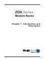
ZDX Series
Modem Racks
Chapter 1 - Introduction and
Description
ZDX Series Modem Racks Owner's Manual
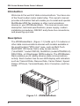
Introduction
Welcome to the world of data communications. You have one
of the finest modem racks made today. This owner's manual
provides information that will enable you to install and operate
MultiModemZDX fax modems or other communications
devices in your ZDXModemRack. This manual covers rack
description, technical specifications, power supply, modem
installation procedures, RS232C and phone line connections,
and powering-up mode.
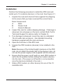
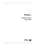
Description
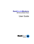
The ZDXModemRack (Figure 1-1) holds up to 12 modems or
other data communications devices with models available in
the small footprint "ZDX style" case, such as Multi-Tech
MultiFRAD 100 Series frame relay access device
("UnoFRAD," model FR2100), MultiDSU (model MT56DSU-S)
DSU/CSUs, or IWayHopper ISDN modems. The ZDXModemRack enables you to readily observe data communications
activity. Each modem has its own LED display with indicators
such as Transmit Data, Receive Data, Carrier Detect, Speed
Status, Off Hook, Terminal Ready, Error Correction, and Fax
mode.
SD
RD
CD
14
96
E4
DH
TR
EC
FX
SD
RD
CD
14
96
E4
DH
SD
TR
RD
EC
CD
FX
14
SD
96
RD
E4
CD
DH
14
TR
96
EC
E4
FX
DH
SD
TR
RD
EC
CD
FX
14
SD
96
RD
E4
CD
DH
14
SD
TR
96
RD
EC
E4
CD
FX
DH
14
SD
TR
96
RD
EC
E4
CD
FX
DH
14
TR
96
EC
E4
FX
DH
SD
TR
RD
EC
CD
FX
14
SD
96
RD
E4
CD
DH
14
TR
96
EC
E4
FX
DH
SD
TR
RD
EC
CD
FX
14
96
E4
DH
TR
EC
FX
SD
RD
CD
14
96
E4
DH
TR
EC
FX
Figure 1-1. ZDXModemRack
8
Chapter 1 - Introduction and Description
The rack is equipped with a redundant, universal input
90-240v AC, 50/60 Hz power supply module. The rack, which
measures 19 inches wide by 5-1/4 inches high, can be
mounted in the same cabinet as your computer, or in a
separate cabinet. Modem installation is accomplished by
simply opening the rack door and sliding in the modems.
RS232C cables and phone cords are connected to the
modem's connectors at the back of the rack.
9
ZDX Series Modem Racks Owner's Manual
Technical Specifications
Rack Capacity:
Up to 12 compact communication devices
Connectors:
IEC 320 Input Power Connector
Dimensions:
19" wide x 5-1/4" high x 7-3/4" deep
48.26cm wide x 13.28cm high x 19.6cm deep
Weights:
Rack with power supply: 8 lbs (3.6 kg)
Rack with power supply and 12
modems: 14.5 lbs (6.6 kg)
Power Supply
Input:
Output:
90 to 240 Volts AC, 2.0 Amps
2-Amp Slo-Blo fuse
+9 volts DC, regulated
4.4 Amps, maximum
Power
Consumption:
40 watts, for a fully loaded rack
Ambient
Temperature:
32° to 104° F (0° to 40° C)
Indicators:
Two LEDs indicate the presence of
AC input power and 5 Volts DC power
Note: for specifications of installed modems or other devices,
refer to the owner's manual for the device.
10
ZDX Series
Modem Racks
Chapter 2 - Installation
ZDX Series Modem Racks Owner's Manual
Power-Up Preliminaries
MultiModemZDX modems are shipped with Command mode
enabled and the DTR signal controlled by the interface. It is
generally assumed that rackmount modems are used in a
central site computer environment (i.e., connected to a mini or
mainframe computer) to automatically answer incoming calls
from remote users.
Unless you need to give the modem commands, you should
disable Command mode. Leaving Command mode enabled
offers the possibility of a user calling into the modem and
reconfiguring it, or causing it to dial out to another location.
Refer to the appropriate modem owner’s manual to configure
the modem for your application.
Safety Warnings
1. Never install telephone wiring during a lightning storm.
2. Never install telephone jacks in wet locations unless the
jack is specifically designed for wet locations.
3. Never touch uninsulated telephone wires or terminals
unless the telephone line has been disconnected at the
network interface.
4. Use caution when installing or modifying telephone lines.
5. Avoid using a telephone (other than a cordless type)
during an electrical storm. There may be a remote risk of
electrical shock from lightning.
6. Do not use the telephone to report a gas leak in the
viciinity of the leak.
7. This product is for use only with listed computers, or
equivalent.
12
Chapter 2 - Installation
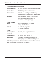
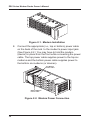
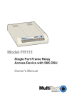
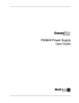
Installation
Perform the following procedure to install the ZDX rack and
install up to 12 modems (devices) in the rack. See Figure 2-1.
1. Unpack the rack and check all items against the shipping
list to ensure that you have received the correct items.
Rack Components
A.
B.
C.
Rack
Power Cord
Owner's Manual
2. Inspect the rack for visible shipping damage. If damage is
observed, do not power-on the rack; contact Multi-Tech's
Technical Support for advice (refer to Chapter 3).
3. If no damage is observed, mount the rack in a standard
19-inch wide rack enclosure. Use standard mounting
hardware supplied with the rack enclosure.
4. Open the front door of the ZDX rack.
5. Unpack the ZDX modems (devices) to be installed in the
rack.
Note: Because of the limited height clearance in the ZDX
rack, do not attach the plastic feet to the devices; also, do
not use the power supply cords supplied with the devices.
6. Ensure that the power on/off swith on each ZDX modem is
set to the On position before sliding the modem (device)
into the rack. (The power on/off switch is not accessible
once the deviceis installed in the rack.)
7. Slide a ZDX modem (or other device) into one of the 12
available slots.
13
ZDX Series Modem Racks Owner's Manual
SD
RD
CD
14
96
E4
DH
TR
EC
FX
SD
RD
CD
14
96
E4
DH
SD
TR
RD
EC
CD
FX
14
SD
96
RD
E4
CD
DH
14
TR
96
EC
E4
FX
DH
SD
TR
RD
EC
CD
FX
14
SD
96
RD
E4
CD
DH
14
SD
TR
96
RD
EC
E4
CD
FX
DH
14
SD
TR
96
RD
EC
E4
CD
FX
DH
14
TR
96
EC
E4
FX
DH
SD
TR
RD
EC
CD
FX
14
SD
96
RD
E4
CD
DH
14
TR
96
EC
E4
FX
DH
SD
TR
RD
EC
CD
FX
14
96
E4
DH
TR
EC
FX
SD
RD
CD
14
96
E4
DH
TR
EC
FX
Figure 2-1. Modem Installation
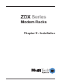
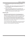
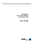
8. Connect the appropriate (i.e., top or bottom) power cable
on the back of the rack to the modem's power input jack.
(See Figure 2-2.) You may have to hold the modem
(device) in place from the front while connecting the power
cable. The top power cable supplies power to the top six
modems and the bottom power cable supplies power to
the bottom six modems (or devices).
Top Modem
Power Cable
Bottom Modem
Power Cable
Figure 2-2. Modem Power Connection
14
Chapter 2 - Installation
9. Repeat steps 6 through 8 for the remaining modems
(devices).
10. If necessary, refer to the modem (device) Owner's Manual
for connecting the cables and telephone lines to the
modems (devices).
11. When all the modems (devices) are connected to the
computer and the telephone lines, plug the AC power cord
supplied with the rack into the power cord connector on
the back of the rack and to a live AC outlet.
Powering Up
Once power is applied to the rack, the modems perform a
diagnostic self-test, indicated by the speed LEDs flashing in
sequence for approximately two seconds, then the 96, 14, 28,
33, or 56 (depending on the type of device installed) should
light. If none of the modems have power applied to them,
check the power cord connection to the rack, then check that
the AC outlet is live. If one or more modems do not power up,
check the power connections to them.
If one of the green power supply LEDs on the front of the rack
is not on, then one of the redundant power supplies may be
defective (or disconnected from input power).
15
ZDX Series Modem Racks Owner's Manual
16
ZDX Series
Modem Racks
Chapter 3 - Service, Warranty
and Tech Support
ZDX Series Modem Racks Owner's Manual
Introduction
This chapter starts out with statements about your modem
rack's 2-year warranty. The next section, Tech Support,
should be read carefully if you have questions or problems
with your rack. It includes the technical support telephone
numbers, space for recording your product information, and an
explanation of how to send in your modem rack should you
require service. The final three sections explain how to use our
bulletin board service (BBS), and get support through
CompuServe and the Internet.
Limited Warranty
Multi-Tech Systems, Inc. (“MTS”) warrants that its products
will be free from defects in material or workmanship for a
period of two years from the date of purchase, or if proof of
purchase is not provided, two years from date of shipment.
MTS MAKES NO OTHER WARRANTY, EXPRESSED OR
IMPLIED, AND ALL IMPLIED WARRANTIES OF
MERCHANTABILITY AND FITNESS FOR A PARTICULAR
PURPOSE ARE HEREBY DISCLAIMED. This warranty does
not apply to any products which have been damaged by
lightning storms, water, or power surges or which have been
neglected, altered, abused, used for a purpose other than the
one for which they were manufactured, repaired by the
customer or any party without MTS’s written authorization, or
used in any manner inconsistent with MTS’s instructions.
MTS’s entire obligation under this warranty shall be limited (at
MTS’s option) to repair or replacement of any products which
prove to be defective within the warranty period, or, at MTS’s
option, issuance of a refund of the purchase price. Defective
products must be returned by Customer to MTS’s factory
transportation prepaid.
18
Chapter 3 - Service, Warranty and Tech Support
MTS WILL NOT BE LIABLE FOR CONSEQUENTIAL
DAMAGES AND UNDER NO CIRCUMSTANCES WILL ITS
LIABILITY EXCEED THE PURCHASE PRICE FOR
DEFECTIVE PRODUCTS.
Tech Support
Multi-Tech has an excellent staff of technical support
personnel available to help you get the most out of your MultiTech product. If you have any questions about the operation
of this unit, call 1-800-972-2439. Please fill out the modem
rack information (below), and have it available when you call. If
your modem rack requires service, the tech support specialist
will guide you on how to send in your rack (refer to the Service
section of this chapter).
Recording Rack Information
Please fill in the following information on your Multi-Tech rack.
This will help tech support in answering your questions. (The
same information is requested on the Warranty Registration
Card.)
Model No.: _____________________________________
Serial No.: _____________________________________
Devices Installed: ___________________________________
The model and serial numbers are on the rack.
Please note any diagnostic test results. Use the space below
to note rack status:
_________________________________________________________________________________
_________________________________________________________________________________
_______________________________________________________________________________
________________________________________________________________________________________________________
___________________________________________________________________________________________________________________
19
ZDX Series Modem Racks Owner's Manual
Service
If your tech support specialist decides that service is required,
your rack can be sent (freight prepaid) to our factory. Return
shipping charges will be paid by Multi-Tech Systems.
Include the following with your rack:
•
a description of the problem.
•
return billing and return shipping addresses.
•
contact name and phone number.
•
check or purchase order number for payment if the rack is
out of warranty. (Check with your technical support
specialist for the standard repair charge for your rack).
•
if possible, note the name of the technical support
specialist with whom you spoke.
If you need to inquire about the status of the returned product,
be prepared to provide the serial number of the product sent
(see Recording Rack Information on the previous page).
Send your rack to this address:
MULTI-TECH SYSTEMS, INC.
2205 WOODALE DRIVE
MOUNDS VIEW, MINNESOTA 55112
ATTN: SERVICE OR REPAIRS
You should also check with the supplier of your CC1600series modem rack on the availability of local service and/or
loaner units in your area.
20
Chapter 3 - Service, Warranty and Tech Support
The Multi-Tech BBS
For customers who do not have Internet access, Multi-Tech
maintains a bulletin board system (BBS) that mirrors its FTP
site. Information available from the BBS includes new product
information, product upgrade files, and problem-solving tips.
The phone number for the Multi-Tech BBS is (800) 392-2432
(USA and Canada) or (612) 785-3702 (international and local).
The BBS can be accessed by any asynchronous modem
operating at 1200 bps to 33,600 bps at a setting of 8 bits, no
parity, and 1 stop bit (8-N-1).
To log on to the Multi-Tech BBS
1. Set your communications program to 8-N-1.
2. Dial our BBS at (800) 392-2432 (USA and Canada) or
(612) 785-3702 (international and local).
3. At the prompts, type your first name, last name, and
password; then press ENTER. If you are a first time caller,
the BBS asks if your name is spelled correctly. If you
answer yes, a questionnaire appears. You must complete
the questionnaire to use the BBS on your first call.
4. Press ENTER until the Main Menu appears. From the
Main Menu you have access to two areas: the Files Menu
and News. For help on menu commands, type ?.
To Download a file
If you know the file name
1. From the Main Menu, type F to access the Files Menu,
then type D.
2. Enter the name of the file you wish to download from the
BBS.
3. If a password is required, enter the password.
4. Answer Y or N to the automatic logoff question.
21
ZDX Series Modem Racks Owner's Manual
5. Select a file transfer protocol by typing the indicated letter,
such as Z for Zmodem (the recommended protocol).
6. If you select Zmodem, the transfer will begin automatically.
If you select another protocol, you may have to initiate the
transfer yourself. (In most datacomm programs, the PAGE
DOWN key initiates the download.)
7. When the download is complete, press ENTER to return to
the File Menu.
8. To exit the BBS, type G and press ENTER.
If you don’t know the file name
1. From the Main Menu, type F to access the Files Menu. For
a list of file areas, type L, press ENTER, then type L and
press ENTER again. (If you do not type the second L, you
will list all of the files on the BBS.)
2. Mark each file area you would like to examine by typing its
list number and pressing ENTER.
3. Enter L to list all the files in the selected file areas. Enter C
to go forward in the file list and P to go back.
4. To mark one or more files for download, type M, press
ENTER, type the list numbers of the files, and press
ENTER again.
5. Enter D. You will see a list of the files you have marked.
Enter E if you would like to edit the list; otherwise enter D
again to start the download process.
6. Select a file transfer protocol by typing the indicated letter,
such as Z for Zmodem (the recommended protocol).
7. If you select Zmodem, the file will transfer automatically. If
you select another protocol, you may have to initiate the
transfer yourself. (In most data communications programs,
the PAGE DOWN key initiates the download.)
8. When the download is complete, press ENTER to return to
the File Menu.
9. To exit the BBS, type G and press ENTER.
22
Chapter 3 - Service, Warranty and Tech Support
About CompuServe
In addition to the BBS, Multi-Tech provides support through
CompuServe's Modem Vendor Forum (GO MODEMVEN).
Refer to your CompuServe documentation for special
operating procedures.
About the Internet
Multi-Tech is a commercial provider on the Internet. If you
prefer to receive service via the internet, you can contact Tech
Support via e-mail at the following address:
http://www.multitech.com/_forms/email_tech_support.htm
Multi-Tech's presence includes a Web site at:
http://www.multitech.com
and an ftp site at:
ftp://ftp.multitech.com
About the Multi-Tech Fax-Back Service
Multi-Tech’s fax-back system provides 24-hour access to
sales, marketing, and technical literature. Dial 612-717-5888,
follow the voice prompts, and request document number 10 for
a catalog of available documents. For convenence, have your
fax number handy: _________________________. From the
catalog of available documents, you can order newsletters,
white papers, press releases, etc. from the sales and
marketing index, or order basic modem operation and
troubleshooting guides from the technical support and
engineering index. Just enter the applicable FB Doc. # from
the left column of the catalog.
23
ZDX Series Modem Racks Owner's Manual
24
ZDX Series
Modem Racks
Appendices
ZDX Series Modem Racks Owner's Manual
Appendix A - Safety Requirements
1. No manual adjustments to the equipment are necessary
for connection to mains power within rated voltage and
frequency.
2. The power supply cord is intended to serve as the
disconnect device. The socket-outlet must be installed
near the equipment and be easily accessible.
3. To reduce the risk of shock, all openings should be
covered during normal operation of the equipment.
4. Use only plugs and cordage for connection of the power
supply to primary power which meets the safety and
regulatory requirements in the country of use.
5. Conductors must have a cross-sectional area of not less
than 1.00 mm2.
Exigences de sécurité
1. Aucun réglage manuel de l'équipement n'est nécessaire
pour des connexions à l'alimentation principale sous une
tension et une fréquence nominales.
2. Le cordon d'alimentation a été conçu pour servir de
dispositif de déconnexion. La prise d'alimentation doit être
installée près de l'équipement et doit être facile d'accès.
3. Afin de réduire les risques de choc, toutes les ouvertures
doivent être couvertes pendant le fonctionnement normal
de l'équipement.
4. N'utiliser que des prises et cordons d'alimentation
répondant aux normes de sécurité du pays de destination.
5. La superficie de la section des conducteurs doit être
supérieure ou égale à 1,00 mm2.
26
Appendix A - Safety Requirements
Requisitos de seguridad
1. No son necesarios ajustes manuales del equipo para la
conexión a la corriente de la red dentro del voltaje y
frecuencia establecidas.
2. El conector de alimentación de energía sirve como
dispositivo de desconexión. La toma de corriente se debe
instalar cerca del equipo y tener un acceso sencillo.
3. Para reducir el riesgo de sacudida eléctrica, todas las
aberturas deben estar cubiertas durante el manejo normal
del equipo.
4. Utilice solamente los enchufes y cables para la conexión
del suministro de energiá a la energiá primaria que
cumplan con los requerimientos regulativos y de
seguridad del país en que se usen.
5. Los conductores deben tener un área transversal mayor
de 1,00 mm2.
Sicherheitsanforderungen
1. Bei Anschluß am Versorgungsnetz innerhalb der
Nennleistung und -frequenz ist es nicht erforderlich,
dieses Gerät manuell nachzustellen.
2. Die Netzschnur dient als Trennvorrichtung. Die Steckdose
muß in der Nähe des Geräts installiert werden, um leicht
zugänglich zu sein.
3. Um Elektroschockgefahr zu vermindern, müssen beim
normalen Betrieb des Geräts alle Öffnungen abgedeckt
sein.
4. Zum Anschluß an das Primärstromnetz nur Stecker und
Anschlußkabeln benutzen, die den Sicherheits- und
Überwachungsvorschriften des Landes entsprechen, in
dem sie angewendet werden.
5. Leitungsdrähte müssen einen Durchmesser von
mindestens 1,00 mm2 haben.
27
ZDX Series Modem Racks Owner's Manual
Mains Wiring Instructions (U.K.)
When wiring the mains plug, the following instructions must be
followed:
•
the core which is coloured green and yellow must be
connected to the terminal in the plug which is marked with
the letter E or by the earth symbol , or coloured green
and yellow.
•
the core which is coloured blue must be connected to the
terminal which is marked with the letter N or coloured
black.
•
the core which is coloured brown must be connected to
the terminal which is marked with the letter L or coloured
red.
Power Requirements
AC 90-245V, 50/60 Hz, 2.0A
DC 40-56V, 2.5A
CAUTION: Safety requirements are not fulfilled unless the
equipment is connected to a wall outlet socket that is provided
with an earth contact.
Alimentation Requise
C.A. 90-245 V, 50/60 Hz, 2.0A
DC 40-56V, 2.5A
ATTENTION: Les conditions de sécurité ne sont pas remplies
si votre équipement n'est pas branché sur une prise murale
avec mise à la terre.
28
Appendix A - Safety Requirements
Requisitos de potencia
C.A. 90-245 V, 50/60 Hz, 2.0 Amp
DC 40-56V, 2.5A
ATTENCION: Adviertase que los requisitos respecto a
medidas de seguridad no quedan satisfechos a menos que
este equipo eléctrico esté conectado a una toma de corriente
mural conectada a tierra.
Stromaufnahme
AC 90-245V, 50/60 Hz, 2.0A
DC 40-56V, 2.5A
VORSICHT: Die Sicherheitsvorschriften sind nur erfüllt, wenn
das Gerät an eine geerdete Wandsteckdose angeschlossen
ist.
29