1
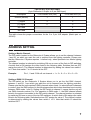
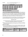
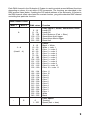
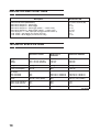
Robocolor II System
users guide
CONTENTS
INTRODUCTION . . . . . . . . . . . . . . . . . . . . . . . . . . . . . . . . . . . . . . . . . . . . . . . .
3
INSTALLING THE ROBOCOLOR II SYSTEM . . . . . . . . . . . . . . . . . . . . . . . . . . .
3
OPERATING WITHOUT A LIGHTING CONTROLLER - STAND ALONE . . . . . .
4
OPERATING STAND ALONE IN MASTER/SLAVE MODE . . . . . . . . . . . . . . . . . .
5
OPERATING VIA A LIGHTING CONTROLLER . . . . . . . . . . . . . . . . . . . . . . . . . .
5
ADDRESS SETTING . . . . . . . . . . . . . . . . . . . . . . . . . . . . . . . . . . . . . . . . . . . . .
7
SPECIAL DIP-SWITCH SETTINGS . . . . . . . . . . . . . . . . . . . . . . . . . . . . . . . . .
10
TECHNICAL SPECIFICATIONS . . . . . . . . . . . . . . . . . . . . . . . . . . . . . . . . . . . .
10
INTRODUCTION
The Robocolor II is a high performance, color changing spotlight which features:
250W/120V ENH lamp.
11 dichroic colors, plus white and blackout.
Color split effects.
Variable strobe effect.
Precision optics with adjustable focus.
All functions DMX 512 and Martin RS-485 implemented.
Built-in sequences with auto and music trigger.
Electronic voltage control combined with BIAS option and soft start ensures long lamp-life.
High quality stepper motor.
Efficient fan cooling.
Overheat thermostat.
INSTALLING THE ROBOCOLOR II SYSTEM / ROBOCOLOR II MOBILE
A Robocolor II System consists of two different units: The Robocolor II Heads, which are the
color changing spotlights, and the Robocolor II Controller, which is the driver unit. You can
connect either two or four Robocolor II Heads to one Robocolor II Controller. In the
Robocolor II Mobile, one Robocolor II Controller and four Robocolor II Heads are built into
one flight-case. Apart from the flight-case, the Robocolor II System and the Robocolor II
Mobile provides the same performance.
3
WARNING!
Do not attempt to operate the Robocolor II Heads without the Robocolor II Controller
(e.g. plugging the Robocolor II directly into the mains outlet)
as damage may occur to the units.
Before attempting any of the following, ensure that the Robocolor II Controller is
disconnected from the mains supply.
Remove the 2 finger screws on the top-cover of each Robocolor II Head and carefully
remove the covers. The lamps can now be installed in the lamp holders. Ensure that
the lamps are pressed firmly into the lamp holders.
Replace the top-covers and tighten the finger screws. You can now install the Robocolor
II Heads in the desired positions. You are allowed to tilt the units ± 90 degrees from
horizontal position. Do not turn the units upside down.
For each Robocolor II Head plug the power cable into the dedicated socket on the
Robocolor II Controller, and then the motor cable into the 5-pin DIN socket of the same
channel. If the Robocolor II Controller is a 230V model you must connect a Robocolor II
Head to both socket 1 and 2 or 3 and 4 as the lamps are series connected.
NOTE: Do not attempt to connect more than one Robocolor II Head to each of the four
output sockets.
NOTE: It is NOT recommended to pair worn lamps with new ones, or, to pair lamps of
different brands as variations in specifications may shorten the lamp life. This only
concerns the 230 V model where head 1 & 2 and 3 & 4 are series connected.
OPERATING WITHOUT A LIGHTING CONTROLLER - STAND ALONE
You can now operate the Robocolor II System in the Stand Alone mode which means that
the Robocolors will perform a pre-programmed sequence at a pre-set speed or triggered by
sounds picked up by the microphone built into the Robocolor II Controller. Before applying
power to the Robocolor II Controller, you will need to set the DIP-switch according to the
sequence you wish to run. The sequence settings table on page 10 shows the various DIPswitch settings for Stand Alone Sequences. E.g. switching on DIP-switch 1, 2 and 10 will
make the Robocolor II System perform an auto triggered stand alone sequence.
Note: Some sequence settings shown on the sequence setting table are for service use only
and should NOT be selected for light performances.
4
OPERATING STAND ALONE IN MASTER/SLAVE MODE
If you have two or more Robocolor II Systems, this feature - Stand Alone in Master/Slave
mode - allows you to operate all systems in perfect synchronisation. You must assign one,
and only one, Robocolor II Systems to be master and all the rest to be slaves. Please
follow the procedure listed below:
On the Master System set the DIP-switch to the desired Stand Alone Sequence as
described in the previous section. Remember, only one unit must be set to master.
On all the Slave Systems set DIP-switch number 1 ON and all others, i.e. 9 to 10, OFF.
Insert a 120 Ohm female XLR termination plug (Martin Part no. 309952) in the male XLR
socket of the master system.
To allow the master system to transmit data to the slaves you will need to daisy-chain all
Robocolor II Systems. Using XLR/XLR cables, connect the data output of the Master
System to the data input of the first Slave System. Then connect the data output of the
first Slave System to the data input of the next, and so on. The order in which the
systems are connected is not important - use an order which gives the easiest and
shortest cable routing.
Finally, insert a male XLR termination plug (Martin part no. 309950) in the last RoboColor
II System on the link and apply power.
IMPORTANT!
It is vital that ONE, and only one, system is set as master and ALL others as slaves.
Otherwise damage to the electronic circuitry may occur.
OPERATING VIA A LIGHTING CONTROLLER
The way to benefit most from your Robocolor II System is by operating it via a lighting
controller. The Robocolor II System accepts two different protocols - Martin RS-485 and
DMX 512. All data (instructions) go from the controller, via XLR/XLR data cables, to the data
input (3 pin male XLR) on the Robocolor II System. The data output (3 pin female XLR)
on the Robocolor II System allows you to continue the serial data link to further units.
The following instructions describe how to make a proper serial data link:
1 Connect the data output on your lighting controller to the data input on the first Robocolor
II System. If you are using a Martin lighting controller then use the XLR-XLR / DSUB-XLR
cable supplied with the controller. Otherwise, use a cable that plugs into your DMX 512
lighting controller and the Robocolor II System. This would normally be a cable that
adapts from 5 pin XLR to 3 pin XLR. The following table shows the proper connections
in such a cable. Please note that the (+) and (-) wires swap from the DMX output to the
input on the Robocolor II System.
2 If you are using one Robocolor II System only, then insert a terminating plug into the
5
3
4
5
6
7
unused data output socket on the unit. This plug is supplied with all Martin controllers and
has a 120 Ohm resistor between pin 2 and 3 (Martin part no. 309950).
If you are using more than one unit with the lighting controller then connect the data
output on each unit to the data input on the following, using XLR-XLR cables. The order,
in which you connect the units, is not important and has no influence on the channels as
far as the controller is concerned - use an order which gives the easiest and shortest
cable routing. To ensure proper transmission on the data link it is very important to insert
the XLR terminating plug in the last fixture on the link.
Use the DIP-switch to select the desired controller channel(s) on each of the units. If you
are not familiar with this, read the following section named ’ADDRESS SETTING’. Ensure
that none of the Robocolor II Systems are set to Stand Alone mode.
Switch on, and configure the controller (please refer to the controller’s manual). Then
apply power to the Robocolor II Systems.
A short start-up and test routine will now be performed and the units will await data to be
transmitted from the controller.
You can now start operating the Robocolors. As soon as the units receive data from the
controller they automatically detect whether DMX 512 or Martin RS-485 signals are sent
and respond accordingly.
NOTE: It is possible to insert other brands of DMX lights (with 5 pin XLR in and out) on
the link. In that case you will need a cable that adapts from the 3 pin female output on
the Martin light to the 5 pin input on the following DMX light. This cable is shown in
number two of the following tables (Martin part no. 309163).
5 pin XLR to 3 pin XLR cable
(5 pin DMX Output to 3 pin Robocolor II Input)
Description
5 Pin male XLR (Out)
3 Pin female XLR (In)
Ground (screen)
1
1
(-) signal
2
3
(+) signal
3
2
Not used
4
Not used
5
This table shows the proper connections for the 5 to 3 pin XLR adapter (Martin part no.
309162).
6
3 pin XLR to 5 pin XLR cable
(3 pin Robocolor II Output to 5 pin DMX Input)
Description
3 Pin female XLR (Out)
5 Pin male XLR (In)
Ground (screen)
1
1
(-) signal
3
2
(+) signal
2
3
Not used
4
Not used
5
This table shows the proper connections for the 3 to 5 pin XLR adapter (Martin part no.
309163).
ADDRESS SETTING
Setting a Martin Channel:
The DIP-switch located on the Robocolor II System allows you to set the channel, between
1 and 32, on which you want the unit to respond from the lighting controller. Please note
that the Robocolor II System requires 1 channel only, when operated via a Martin lighting
controller.
The channel number is selected by switching ON one or more of the first six DIP-switches.
A switch that is ON, assigns the value listed in the following table. Switches that are OFF
assign the value 0. The channel number is determined by adding the values from switch 1
to 6. Note that switch 7 to 10 should all be OFF.
Example:
Pin 1, 2 and 5 ON will set channel = 1 + 2 + 0 + 0 + 16 + 0 = 19.
Setting a DMX 512 Channel:
The DIP-switch on the Robocolor II System allows you to set the first DMX channel,
between 1 and 511, from which you want the unit to respond from the lighting controller.
Please note that the unit requires 5 DMX channels when mode 1 is selected and 6 channels
in mode 2 (see the DMX protocol in the following section which also describes how to switch
between DMX mode 1 and 2). Setting the DIP-switch to channel 1 means that the unit will
use DMX channels number 1 to 5 for operation in DMX mode 1 - the DMX channel offsets
listed in the protocol are added to the DIP-switch channel. The channel number is selected
by switching ON one or more of the ten DIP-switches. A switch that is ON assigns the value
listed in the following table. Switches that are OFF assign the value 0. The channel number
is determined by adding the values from switch 1 to 9. Note that switch 10 should be
switched OFF.
7
Example:
Pin 2, 3, 7 and 8 ON will set DMX channel = 0 + 2 +
4 + 0 + 0 + 0 + 64 + 128 + 0 = 198.
DIP-Switch values
Switch
Value
Switch
Value
Switch
Value
Switch
Value
1
1
4
8
7
64
10
OFF
2
2
5
16
8
128
3
4
6
32
9
256
DMX 512 PROTOCOL
All features in the Robocolor II System are fully DMX implemented. When operating via
DMX you can choose between two modes: Tracking (mode 1) and Vector & Tracking (mode
2). Tracking mode means that the speed of a color scroll is determined by the change in
DMX value per time unit, i.e. color wheel is tracking the slope generated by the DMX
controller. The more rapidly the DMX value changes the faster the color scroll becomes.
When working in vector mode, the scroll speed is determined by a speed value set on a
separate DMX channel. This channel also allows you to enable tracking mode.
You can switch between DMX mode 1 and 2 by placing or removing a jumper on the printed
circuit board (PCB) inside the unit. This jumper is located on a connecter labelled PL113 and
should be set according to the table below. Follow this procedure to set the jumper:
WARNING!
To avoid electrical shock or damage to the unit, ensure that it is disconnected
from the mains supply before attempting any of the following.
Remove the six Philips screws which secure the cover on the Robocolor II Controller. If
you have a Robocolor II Mobile there are six Philips screws on the sides of the lid, which
you will have to remove.
Remove the cover/lid.
There are two PCBs inside the unit. On the one without the aluminium heat sink, locate
the 4 pin connector labelled PL113. On this connecter you will see a jumper (a small
device that makes connection between two adjacent pins). Set the jumper according to
the following table, thus selecting the desired DMX mode.
DMX Setup
DMX Requirements
PL113 Jumper setting
Mode 1 - Tracking (factory default)
5 Channels
No Jumper
Mode 2 - Tracking/Vector
6 Channels
Pin 1 and 2
8
Each DMX channel in the Robocolor II System is used to provide several different functions
depending on where it is set within 0-255 increments. The functions are described in the
DMX protocol listed below. If adding the DIP-switch address of the Robocolor II System to
the DMX channel offset value listed for a certain function, you get the absolute DMX channel
controlling that particular function.
DMX Channel Offset
Mode 1
Mode 2
0
1-4
(Head 1 - 4)
-
5
DMX values
Function
0 - 10
11 - 74
75 - 138
139 - 170
171 - 202
203 - 255
Lamp ON/OFF, Strobe, Stand-Alone, Reset
Lamp OFF
Lamp ON
Color-Strobe on (Fast -> Slow)
Stand-Alone Auto trigger
Stand-Alone Music trigger
Reset Unit
0 - 15
16 - 30
31 - 45
46 - 60
61 - 75
76 - 90
91 - 105
106 - 120
121 - 135
136 - 150
151 - 165
166 - 180
Colors
Black -> White
White -> color 1
Color 1 -> color 2
Color 2 -> color 3
Color 3 -> color 4
Color 4 -> color 5
Color 5 -> color 6
Color 6 -> color 7
Color 7 -> color 8
Color 8 -> color 9
Color 9 -> color 10
Color 10 -> color 11
181
185
190
195
200
205
210
215
220
225
230
235
240
Color 11
Color 10
Color 9
Color 8
Color 7
Color 6
Color 5
Color 4
Color 3
Color 2
Color 1
White
Black
-
184
189
194
199
204
209
214
219
224
229
234
239
255
0
1 - 255
Color Speed
Tracking
Speed (fast -> slow)
9
SPECIAL DIP-SWITCH SETTINGS
Description
DIP-switches ON
Protocol auto-detect (DMX/Martin)
Stand Alone Sequence - Auto-trigger
Stand Alone Sequence - Music-trigger
Stand Alone Sequence - Auto-trigger (Head 1 - 4 same color)
Stand Alone Sequence - Music-trigger (Head 1 - 4 same color)
Color adjust pos. 1 / color adjust pos 2 (toggle with DIP-switch 1)
L.E.D. Chase - Auto-trigger (for service use only)
L.E.D. Chase - Music-trigger (for service use only)
1,2,3,4,5,6,7,8,9,10 (All)
2,10
1,2,10
2,3,10
1,2,3,10
(1),5,10
4,10
1,4,10
TECHNICAL SPECIFICATIONS
Robocolor II Head
Robocolor II
Controller
Robocolor II Mobile
Length:
Width:
Height:
180 mm
160 + 40 mm (handle)
150 + 70 mm (bracket)
276 mm
125 mm
85 mm
1385 mm
225 mm
405 mm
Weight:
3.0 kg
2.5 kg
28 kg
Power consumption:
250 W
N/A
1000 W
AC supply
230 volt model:
115 volt model:
N/A
N/A
200-270 V / 50-60 Hz
100-130 V / 50-60 Hz
200-270 V / 50-60 Hz
100-130 V / 50-60 Hz
Lamp:
250 W / 120 V (ENH)
N/A
250 W / 120 V (ENH)
Beam angle standard:
Beam angle optional:
18°
25°
N/A
N/A
18°
25°
Fuse (primary):
N/A
10 AT / 250 V
10 AT / 250 V
PS-960624
10